evertuff cpvc schedule 40 & 80 marine pressure system
TRANSCRIPT

Marine & Offshore TechnicalEverTUFF® CPVC Schedule 40 & 80 Marine Pressure System
Page 1 Suitable for Oil-Free air handling to 25 psi, not for distribution of compressed air or gas Spears® Manufacturing CompanySee Spears® Product Sourcebook for product offerings
EverTUFF® CPVC Schedule 40 & 80 Marine Pressure System
ENGINEERING GUIDE
TECHNICAL AND INSTALLATION INFORMATIONWITH WEIGHTS & DIMENSIONS
Contact Spears® for any Information not found.

Marine & Offshore TechnicalEverTUFF® CPVC Marine System Design & Installation Guide
Chlorinated polyvinyl chloride (CPVC) is created by post chlorination of the PVC polymer. This produces up to a 60°F higher heat handling capability than PVC and greater fire resistance, plus a broad range of chemical resistance. CPVC is excellent for use in marine process piping, hot and cold water service and other elevated temperature applications. CPVC provides relatively low cost compared to alternative materials for similar use.
CPVC pipe is manufactured by extrusion and CPVC fittings are manufactured by injection molding or fabrication. Spears®
produces a variety of CPVC pipe, fittings, valves, systems accessories and specialty systems.
Spears® high quality CPVC compounds provide optimum chemical and corrosion resistance with a full range of pressure handling capabilities. Spears® CPVC materials are certified by NSF International to applicable standards including NSF® Standard 61 for use in potable water service, certified lead-free, and to ASTM D1784, Ridgid Poly (Vinyl Chloride) (PVC) Compound and Chlorinated Poly (Vinyl Chloride) (CPVC) Compounds that specifies Cell Classification for minimum physical property requirements.
These include resin type, impact strength, tensile strength, modulus of elasticity in tension, heat deflection temperature and flammability. Spears® minimum CPVC Cell Classification is 23447 for ridgid (unplasticized) CPVC.
The ASTM Type and Grade is CPVC Type IV, Grade I and the typical long and short term strength designation of material for pressure piping is CPVC 4120. See Industry Standards and Test Methods, Physical Properties and Chemical Resistance sections for additional information.
Spears® CPVC Marine System Installation InformationEverTUFF® CPVC Marine Schedule 40/80 Pipe & Schedule 80 Fittings Installation Guide.
EverTUFF® CPVC CTS Marine Hot and Cold Water Distribution System Installation Guide.
OceanTUFF™ CPVC Marine Drainage System Installation Guide.
System IntegritySpears® EverTUFF® CPVC marine schedule 40/80 piping systems have been developed and designed to be used as a total marine system consisting of pipe, fittings, accessories, solvent cement and thread sealant. All Spears® EverTUFF® components should be used in order to ensure a sound marine piping system. Substitution of other products for Spears® EverTUFF® CPVC marine pipe, fittings, or solvent cement may be detrimental to system integrity and is not recommended. The Spears® Limited Lifetime Warranty does not cover problems occurring within the marine piping system as the direct result of non-use of Spears® EverTUFF®
CPVC marine system products. Spears® EverTUFF® CPVC marine schedule 40/80 piping systems are approved for use in non-essential spaces of a vessel by ABS and U.S. Coast Guard. Consult with Spears® Manufacturing Company for more information or visit www.spearsmfg.com/marine.htm.
Watertight Deck & Bulkhead PenetrationsSpears® CPVC marine products can be installed in deck and bulkhead penetrations according to their respective approval requirements. Be sure to check the fire stop system and CPVC material compatibility with the fire stop manufacturer. For more information please contact our Technical Support Department at (818) 364-1611.Where it is intended to pass plastic pipes through bulkheads or decks, the original integrity of watertight bulkheads and decks is to be maintained at the location. If the bulkhead or deck is also a fire division and destruction by fire of plastic pipes may cause inflow of liquid from a tank, then a metallic shutoff valve operable from above the bulkhead deck is to be fitted at the bulkhead or deck.Note: Spears® marine approved products have not been tested for "A", "B" or "F" class divisions in accordance with IMO resolution A.754(18), Recommendation on Fire Resistance Tests for "A", "B" and "F" Class Divisions.
Penetrating Structural MembersWood Beams-Spears® EverTUFF® CPVC marine piping can be passed through beams without use of sleeves or insulators. Drill hole 1/4" larger than pipe diameter to allow for expansion and contraction. Floating pipe through beams is advisable.Steel Beams-When EverTUFF® CPVC marine piping passes through steel beams, use compatible plastic insulators, rubber grommets, pipe insulation or similar devices to prevent abrasion and noise. Floating pipe through beams is advisable. Important: Do not penetrate beams, columns or structural members before consulting design engineer.
"Lead Free" low lead certification - unless otherwise specified, all Spears® Plastic Piping specified here-in are certified by NSF International to ANSI/NSF® Standard 61, Annex G and is in compliance with California's Health & Safety Code Section 116825 (commonly known as AB 1953) and Vermont Act 193. Weighted average lead content <=0.25%.
Made in the U.S.A. Suitable for Oil-Free air handling to 25 psi, not for distribution of compressed air or gasSee Spears® Product Sourcebook for product offerings Page 2
The information contained in this publication is based on current information and product design at the time of publication and is subject to change without notification. Our ongoing commitment to product improvement may result in some variation. No representations, guarantees or warranties of any kind are made as to its accuracy, suitability for particular applications or results to be obtained therefrom. For verification of technical data or additional information not contained herein, please contact Spears® Technical Services Department [West Coast: (818) 364-1611 - East Coast: (678) 985-1263].
PURPOSE OF THIS MANUALThis manual is intended as a resource for use by specification engineers, installers, and users in the selection, design and installation of CPVC marine systems installed using Spears® piping systems. All information contained within this manual is considered vital to obtain proper system performance and must be read and fully understood before attempting to install these products. If you have any questions about the safe and proper installation of these products, contact Spears®
Manufacturing Company, 15853 Olden Street, Sylmar CA 91342 USA, Telephone (818) 364-1611.
Spears® CPVC MaterialCPVC

Marine & Offshore TechnicalEverTUFF® CPVC Marine System Design & Installation Guide
1/2" Through 12" Availability
Spears® comprehensive line of CPVC marine fittings and pipe offers a variety of configurations in Schedule 80 sizes 1/2" through 12".
Exceptional Chemical & Corrosion ResistanceUnlike metal, CPVC fittings never rust, scale or pit, and will provide many years of maintenance-free service and extended system life.
Higher Temperature RatingsHigh Temperature CPVC thermoplastics can handle fluids at service temperatures up to 200°F, allowing a wide range of process applications.
Higher Flow CapacitySmooth interior walls result in lower pressure loss and higher volume than conventional metal fittings.
Lower Installation CostsSubstantially lower material costs than copper or steel combined with lighter weight and ease of installation, can reduce installation costs by as much as 60% over conventional metal systems.
1/2" Through 12" CPVC Marine Pipe AvailabilitySpears® premium quality CPVC Schedule 80 is offered is offered in sizes 1/2" through 12". Schedule 40 CPVC marine pipe is also available.
United States Coast Guard ApprovalSpears® EverTUFF® Marine Schedule 40 and Schedule 80 CPVC pipe and Schedule 80 fittings are USCG Approved for use in non-essential marine and offshore applications in nominal pipe sizes 1/2" through 12". Spears® USCG approval details and restrictions are available on the USCG equipment search website at [email protected].
American Bureau of Shipping (ABS) Type ApprovalSpears® EverTUFF® Marine Schedule 40 and Schedule 80 CPVC pipe and Schedule 80 fittings are ABS Type Approved use in non-essential marine and offshore applications in nominal pipe sizes 1/2" through 12". Type Approval details and restrictions are available on the ABS website at www.eagle.org.
Page 3 Suitable for Oil-Free air handling to 25 psi, not for distribution of compressed air or gas Spears® Manufacturing CompanySee Spears® Product Sourcebook for product offerings
CPVC Performance Engineered and Tested
SPEARS® EverTUFF® CPVC Marine pipe and fitting designs combine years of proven experience with computer generated stress analysis to yield the optimum physical structure and performance for each fitting. Material is uniformly placed in areas of high stress concentration for substantially improved pressure handling capability. Resulting products are subjected to numerous verification tests to assure the very best CPVC marine piping products available.

Marine & Offshore TechnicalEverTUFF® CPVC Marine System Design & Installation Guide
Made in the U.S.A. Suitable for Oil-Free air handling to 25 psi, not for distribution of compressed air or gasSee Spears® Product Sourcebook for product offerings Page 4
General InformationRecommendations for Installers and Users
Plastic piping systems should be ENGINEERED, INSTALLED and OPERATED in accordance with ESTABLISHED DESIGN AND ENGINEERING STANDARDS AND PROCEDURES for plastic piping systems. Suitability for the intended service application should be determined by the installer and/or user prior to installation of a plastic piping system. PRIOR TO ASSEMBLY, all piping system components should be inspected for damage or irregularities. Mating components should be checked to assure that tolerances and engagements are compatible. Do not use any components that appear irregular or do not fit properly. Contact the appropriate manufacturer of the component product in question to determine usability. Consult all applicable codes and regulations for compliance prior to installation.
Solvent Weld Connections - Use Marine-24 solvent cement and primers formulated for the intended service application, pipe size and type of joint. While the pipe and fitting materials may be compatible with the intended medium, the solvent cement may not be. Consult the manufacturers for suitability of use. Read and follow the cement and primer manufacturers' applications and cure time instructions thoroughly. Be sure to use the correct size applicator.
Threaded Connections - Use a quality grade thread sealant. WARNING: SOME PIPE JOINT COMPOUNDS OR PTFE PASTES MAY CONTAIN SUBSTANCES THAT COULD CAUSE STRESS CRACKING TO PLASTIC. Spears® Manufacturing company recommends the use of Spears® BLUE 75™ Thread Sealant which has been tested for compatibility with Spears® products. Please follow the sealant manufacturers' application/installation instructions. Choice of an appropriate thread sealant other than those listed above is at the discretion of the installer. 1 to 2 turns beyond FINGER TIGHT is generally all that is required to make a sound plastic threaded connection. Unnecessary OVERTIGHTENING will cause DAMAGE TO BOTH PIPE AND FITTING.
EverTUFF® Marine Schedule 40/80 Pipe & Fittings Sample Engineering Specification
Spears® EverTUFF® Marine Schedule 40 and Schedule 80 pipe and Schedule 80 fittings shall be manufactured by Spears® Manufacturing Company from a Type IV, Grade I Chlorinated Polyvinyl Chloride (CPVC) compound with a Cell Classification of 23447 per ASTM D1784. The pipe and fittings shall be manufactured in strict compliance to ASTM F441 and ASTM F439 respectively consistently meeting the quality assurance test requirements of these standards. All Spears® EverTUFF®
marine pipe and fittings shall be manufactured in the U.S.A. The pipe shall be provided with plain end in 20 foot or 10 foot cut lengths as specified and wrapped for protection. All Spears®EverTUFF® marine CPVC pipe and fittings shall be certified by NSF International for potable water applications and marked accordingly and available in sizes 1/2" through 12". All Spears® EverTUFF® marine CPVC schedule 40 and schedule 80 pipe shall be approved by the United States Coast Guard, meet the low flame spread requirements and smoke and toxicity requirements of the 2010 FTP Code Annex 1, Parts 2 and 5, and may be installed in accommodation, service and control spaces without meeting the additional requirements of 46 CFR 56.60-25(a)(2) as manufactured by Spears® Manufacturing Company.
All EverTUFF® Marine CPVC Schedule 40 and Schedule 80 pipe and Schedule 80 fittings shall be approved by the American Bureau of Shipping (ABS) and meet IMO FTP Code Annex 1, Part 5 for Surface Flammability and Part 2 for smoke and toxicity with a Limited Lifetime Warranty as manufactured by Spears®
Manufacturing Company. Offshore applications for non-essential systems including fresh water, potable water and brine in services requiring no fire endurance testing or electrical conductivity testing. Piping to be used in non-hazardous areas only.
"Lead Free" low lead certification - unless otherwise specified, all Spears® Schedule 80 fittings specified here-in are certified by NSF International to ANSI/NSF®
Standard 61, Annex G and is in compliance with California's Health & Safety Code Section 116825 (commonly known as AB1953) and Vermont Act 193. Weighted average lead content <=0.25%.

Marine & Offshore TechnicalEverTUFF® CPVC Marine System Design & Installation Guide
Page 5 Suitable for Oil-Free air handling to 25 psi, not for distribution of compressed air or gas Spears® Manufacturing CompanySee Spears® Product Sourcebook for product offerings
Typical Physical Properties of Spears® EverTUFF® CPVC MaterialGENERAL CPVC Value Test Method
Cell Classification 23447 ASTM D 1784
Maximum Service Temperature 200°F
Color Medium Gray
Specific Gravity, (g/cu.cm @ 73°F) 1.51 ASTM D 792
Water Absorption % increase 24 hrs @ 25°C 0.03 ASTM D 570
Hardness, Rockwell 117 - 119 ASTM D 785
Poisson's Ratio @ 73°F 0.370
MECHANICAL
Tensile Strength, psi @ 73°F 7,900 ASTM D 638
Tensile Modulus of Elasticity, psi @ 73°F 426,000 ASTM D 638
Flexural Strength, psi @ 73°F 15,000 ASTM D 790
Flexural Modulus, psi @ 73°F 360,000 ASTM D 790
Compressive Strength, psi @ 73°F 10,000 ASTM D 695
Izod Impact, notched, ft-lb/in @ 73°F 2.9 ASTM D 256
THERMAL
Coefficient of Linear Expansion (in/in/°F) 3.2 X 10 5 ASTM D 696
Coefficient of Thermal Conductivity ASTM C 177
Calories • cm/second • cm2 • °C 3.27 X 10 4
BTU • inches/hour • Ft2 • °F 0.95
Watt/m/K 0.137
Heat Deflection Temperature
Under Load (264 psi, annealed) 235 ASTM D 648
ELECTRICAL
Dielectric Strength, volts/mil 1,250 ASTM D 149
Dielectric Constant, 60Hz, 30°F 3.70 ASTM D 150
Volume Resistivity, ohm/cm @ 95°C 3.4 X 10¹² ASTM D 150
Spears® CPVC Pipe is non-electrolytic
FIRE PERFORMANCE
Flammability Rating V-0, 5VB, 5VA UL-94
Flame Spread-Smoke Development-Toxicity Annex 1, Part 5 & Part 2 2010 FTP Code
Flash Ignition Temp. 900°F
Average Time of Burning (sec.). <5 ASTM D 635
Average Extent of Burning (mm) <10
Burning Rate (in/min) Self Extinguishing
Limiting Oxygen Index (LOI) 60 ASTM D 2863Note: The physical properties shown above are considered general for CPVC. Contact Spears® Technical Services for additional information if necessary.

Marine & Offshore TechnicalEverTUFF® CPVC Marine System Design & Installation Guide
The Hazen-Williams equation below is widely used to calculate friction loss for water through CPVC pipef = .2083 x (100/C)1.852 x G 1.852
di 4.8655
Where:f = Friction head of feet of water per 100' for the specific pipe size and I.D.C = A constant for internal pipe roughness (=150 for thermoplastic pipe)G = Flow rate of U.S. gallons per minutedi = Inside diameter of pipe in inches
Friction Loss Through Fittings
Pressure Drop In Valves & StrainerPressure drop calculations can be made for valves and strainers for different fluids, flow rates, and sizes using the CV values and the following equation:
Where:
P = (G)2(Sg)
(Cv)2
P = Pressure drop in PSI; feet of water = PSI.4332
G = Gallons per minuteCv = Gallons per minute water per 1 PSI pressure dropSg = Specific gravity of liquid (water =1)
Cv Values for Select Spears® Valves and Strainers
Nominal Size 1/2 3/4 1 1-1/4 1-1/2 2 2-1/2 3 4 6 8 10 12
True Union 2000 Ball Valve1 29 63 120 243 357 599 856 1416 2865 1952 -- -- --
True Union 2000 Ball Check Valve 6.3 17 25 65 86 130 200 275 500 800 -- -- --
Butterfly Valve (90° - Full Open) -- -- -- -- 81 109 192 345 411 1125 2249 4440 6309
1 - Full Port Ball Valve Cv based on equivalent length of Schedule 80 pipe
Water VelocitiesVelocities for water in feet per second at different GPM's and pipe inside diameters can be calculated as follows:
V = .3208 GA
Where:V = velocity in feet per secondr minuteG = gallons per minuteA = inside cross sectional area in square inchecs
Friction loss through fittings is expressed in equivalent feet of the same pipe size and schedule for the system flow rate.
Average Friction Loss for CPVC Fittings in Equivalent Feet of Straight Run Pipe
Item 1/2 3/4 1 1-1/4 1-1/2 2 2-1/2 3 4 6 8 10 12
Tee Run 1.0 1.4 1.7 2.3 2.7 4.0 4.9 6.1 7.9 12.3 14.0 17.5 20.0
Tee Branch 3.8 4.9 6.0 7.3 8.4 12.0 14.7 16.4 22.0 32.7 49.0 57.0 67.0
90° Ell 1.5 2.0 2.5 3.8 4.0 5.7 6.9 7.9 11.4 16.7 21.0 26.0 32.0
45° Ell .8 1.1 1.4 1.8 2.1 2.6 3.1 4.0 5.1 8.0 10.6 13.5 15.5
Made in the U.S.A. Suitable for Oil-Free air handling to 25 psi, not for distribution of compressed air or gasSee Spears® Product Sourcebook for product offerings Page 6
FLOW VELOCITY & FRICTION LOSSFriction Loss Through Pipe

Marine & Offshore Technical
Engineering & Design Data
Page 7 Suitable for Oil-Free air handling to 25 psi, not for distribution of compressed air or gas Spears® Manufacturing CompanySee Spears® Product Sourcebook for product offerings
FLOW VELOCITY & FRICTION LOSS
SCHEDULE 40FlowRate
(Gallons/Minute)
FlowVelocity(ft/sec.)
FrictionLoss
(Ft.Water/100ft)
FrictionLoss(psi/
100ft)
FlowVelocity(ft/sec.)
FrictionLoss
(Ft.Water/100ft)
FrictionLoss(psi/
100ft)
FlowVelocity(ft/sec.)
FrictionLoss
(Ft.Water/100ft)
FrictionLoss(psi/
100ft)
FlowVelocity(ft/sec.)
FrictionLoss
(Ft.Water/100ft)
FrictionLoss(psi/
100ft)
FlowVelocity(ft/sec.)
FrictionLoss
(Ft.Water/100ft)
FrictionLoss(psi/
100ft)
FlowRate
(Gallons/Minute)
GPM 1/2" 3/4" 1" 1-1/4" 1-1/2" GPM
1 1.13 1.16 0.50 0.63 0.28 0.12 0.39 0.09 0.04 0.22 0.02 0.01 1
2 2.25 4.19 1.82 1.26 1.03 0.44 0.77 0.31 0.13 0.44 0.08 0.03 0.32 0.04 0.02 2
5 5.63 22.88 9.92 3.16 5.60 2.43 1.93 1.69 0.73 1.10 0.43 0.19 0.81 0.20 0.09 5
7 7.88 42.66 18.49 4.42 10.44 4.53 2.70 3.14 1.36 1.55 0.81 0.35 1.13 0.38 0.16 7
10 11.26 82.59 35.80 6.31 20.21 8.76 3.86 6.08 2.64 2.21 1.57 0.68 1.62 0.73 0.32 10
15 9.47 42.82 18.56 5.78 12.89 5.59 3.31 3.32 1.44 2.42 1.55 0.67 15
20 12.63 72.95 31.63 7.71 21.96 9.52 4.42 5.65 2.45 3.23 2.64 1.15 20
25 9.64 33.20 14.39 5.52 8.55 3.71 4.04 4.00 1.73 25
30 11.57 46.54 20.17 6.62 11.98 5.19 4.85 5.60 2.43 30
35 7.73 15.94 6.91 5.65 7.45 3.23 35
40 8.83 20.41 8.85 6.46 9.54 4.14 40
45 9.94 25.39 11.00 7.27 11.87 5.15 45
50 11.04 30.86 13.38 8.08 14.43 6.25 50
60 9.69 20.22 8.87 60
GPM 2" 2-1/2" 3" 4" 6" GPM
5 0.49 0.06 0.03 5
7 0.68 0.11 0.05 0.48 0.05 0.02 7
10 0.97 0.21 0.09 0.68 0.09 0.04 0.44 0.03 0.01 10
15 1.46 0.45 0.20 1.02 0.19 0.08 0.66 0.07 0.03 15
20 1.95 0.77 0.34 1.37 0.33 0.14 0.88 0.11 0.05 0.51 0.03 0.01 20
25 2.44 1.17 0.51 1.71 0.49 0.21 1.10 0.17 0.07 0.64 0.05 0.02 25
30 2.92 1.64 0.71 2.05 0.69 0.30 1.32 0.24 0.10 0.77 0.06 0.03 30
35 3.41 2.18 0.94 2.39 0.92 0.40 1.54 0.32 0.14 0.89 0.08 0.04 35
40 3.90 2.79 1.21 2.73 1.18 0.51 1.76 0.41 0.18 1.02 0.11 0.05 40
45 4.39 3.47 1.51 3.07 1.46 0.63 1.99 0.51 0.22 1.15 0.13 0.06 45
50 4.87 4.22 1.83 3.41 1.78 0.77 2.21 0.61 0.27 1.28 0.16 0.07 0.56 0.02 0.01 50
60 5.85 5.92 2.56 4.10 2.49 1.08 2.65 0.86 0.37 1.53 0.23 0.10 0.67 0.03 0.01 60
70 6.82 7.87 3.41 4.78 3.32 1.44 3.09 1.15 0.50 1.79 0.30 0.13 0.79 0.04 0.02 70
75 7.31 8.94 3.88 5.12 3.77 1.63 3.31 1.30 0.56 1.92 0.34 0.15 0.84 0.05 0.02 75
80 7.80 10.08 4.37 5.46 4.25 1.84 3.53 1.47 0.64 2.04 0.39 0.17 0.90 0.05 0.02 80
90 8.77 12.53 5.43 6.15 5.28 2.29 3.97 1.82 0.79 2.30 0.48 0.21 1.01 0.07 0.03 90
100 9.74 15.23 6.60 6.83 6.42 2.78 4.41 2.22 0.96 2.55 0.59 0.25 1.12 0.08 0.03 100
125 12.18 23.03 9.98 8.54 9.70 4.21 5.52 3.35 1.45 3.19 0.89 0.38 1.40 0.12 0.05 125
150 10.24 13.60 5.90 6.62 4.70 2.04 3.83 1.24 0.54 1.68 0.17 0.07 150
175 7.72 6.25 2.71 4.47 1.65 0.72 1.96 0.22 0.10 175
200 8.82 8.00 3.47 5.11 2.12 0.92 2.25 0.29 0.12 200
250 11.03 12.10 5.24 6.39 3.20 1.39 2.81 0.43 0.19 250
300 7.66 4.49 1.95 3.37 0.61 0.26 300
350 8.94 5.97 2.59 3.93 0.81 0.35 350
400 10.22 7.64 3.31 4.49 1.03 0.45 400
450 5.05 1.29 0.56 450
500 5.61 1.56 0.68 500
NOTE: Spears® recommends that Flow Velocities be maintained at or below 5 feet per second in large diameter piping systems (i.e. 6" diameter and larger) to minimize the potential for hydraulic shock. Refer to Spears® engineering section entitled "Hydraulic Shock" for additional information. Friction loss data based on utilizing mean wall dimensions to determine average ID; actual ID may vary.

Marine & Offshore Technical
Engineering & Design Data
Made in the U.S.A. Suitable for Oil-Free air handling to 25 psi, not for distribution of compressed air or gasSee Spears® Product Sourcebook for product offerings Page 8
FLOW VELOCITY & FRICTION LOSS
SCHEDULE 40Flow Rate
(Gallons/ Minute)
Flow Velocity
(ft/sec.)
Friction Loss
(Ft. Water/100ft)
Friction Loss
(psi/100ft)
Flow Velocity
(ft/sec.)
Friction Loss
(Ft. Water/100ft)
Friction Loss
(psi/100ft)
Flow Velocity
(ft/sec.)
Friction Loss
(Ft. Water/100ft)
Friction Loss
(psi/100ft)
Flow Rate
(Gallons/ Minute)
GPM 8" 10" 12" GPM
100 0.65 0.02 0.01 100
125 0.81 0.03 0.01 125
150 0.97 0.04 0.02 150
175 1.13 0.06 0.03 175
200 1.29 0.08 0.03 0.82 0.02 0.01 200
250 1.62 0.11 0.05 1.03 0.04 0.02 250
300 1.94 0.16 0.07 1.23 0.05 0.02 300
350 2.27 0.21 0.09 1.44 0.07 0.03 1.01 0.03 0.01 350
400 2.59 0.27 0.12 1.64 0.09 0.04 1.16 0.04 0.02 400
450 2.91 0.34 0.15 1.85 0.11 0.05 1.30 0.05 0.02 450
500 3.24 0.41 0.18 2.05 0.14 0.06 1.44 0.06 0.02 500
750 4.85 0.87 0.38 3.08 0.29 0.12 2.17 0.12 0.05 750
1000 6.47 1.48 0.64 4.10 0.49 0.21 2.89 0.21 0.09 1000
1250 5.13 0.74 0.32 3.61 0.31 0.14 1250
1500 6.15 1.03 0.45 4.33 0.44 0.19 1500
2000 5.78 0.75 0.33 2000
2500 7.22 1.13 0.49 2500
NOTE: Spears® recommends that Flow Velocities be maintained at or below 5 feet per second in large diameter piping systems (i.e. 6" diameter and larger) to minimize the potential for hydraulic shock. Refer to Spears® engineering section entitled "Hydraulic Shock" for additional information. Friction loss data based on utilizing mean wall dimensions to determine average ID; actual ID may vary.

Marine & Offshore Technical
Engineering & Design Data
Page 9 Suitable for Oil-Free air handling to 25 psi, not for distribution of compressed air or gas Spears® Manufacturing CompanySee Spears® Product Sourcebook for product offerings
FLOW VELOCITY & FRICTION LOSSSCHEDULE 80
FlowRate
(Gallons/Minute)
FlowVelocity(ft/sec.)
FrictionLoss
(Ft. Water/100ft)
FrictionLoss(psi/
100ft)
FlowVelocity(ft/sec.)
FrictionLoss
(Ft. Water/100ft)
FrictionLoss(psi/
100ft)
FlowVelocity(ft/sec.)
FrictionLoss
(Ft. Water/100ft)
FrictionLoss(psi/
100ft)
FlowVelocity(ft/sec.)
FrictionLoss
(Ft. Water/100ft)
FrictionLoss(psi/
100ft)
FlowVelocity(ft/sec.)
FrictionLoss
(Ft. Water/100ft)
FrictionLoss(psi/
100ft)
FlowRate
(Gallons/Minute)
GPM 1/2" 3/4" 1" 1-1/4" 1-1/2" GPM1 1.48 2.24 0.97 0.78 0.48 0.21 0.47 0.14 0.06 0.26 0.03 0.01 0.19 0.01 0.01 1
2 2.96 8.08 3.50 1.56 1.73 0.75 0.93 0.49 0.21 0.52 0.12 0.05 0.38 0.05 0.02 2
5 7.39 44.12 19.12 3.91 9.45 4.10 2.33 2.67 1.16 1.30 0.64 0.28 0.96 0.29 0.13 5
7 10.35 82.27 35.66 5.48 17.62 7.64 3.26 4.98 2.16 1.81 1.20 0.52 1.34 0.54 0.24 7
10 14.78 159.26 69.04 7.82 34.11 14.79 4.66 9.65 4.18 2.59 2.32 1.00 1.92 1.05 0.46 10
15 11.74 72.27 31.33 6.99 20.44 8.86 3.89 4.91 2.13 2.87 2.23 0.97 15
20 15.65 123.13 53.38 9.33 34.82 15.09 5.18 8.36 3.62 3.83 3.80 1.65 20
25 11.66 52.64 22.82 6.48 12.64 5.48 4.79 5.74 2.49 25
30 13.99 73.78 31.98 7.77 17.71 7.68 5.75 8.04 3.49 30
35 16.32 98.16 42.55 9.07 23.56 10.21 6.71 10.70 4.64 35
40 18.65 125.70 54.49 10.37 30.17 13.08 7.66 13.71 5.94 40
45 11.66 37.53 16.27 8.62 17.05 7.39 45
50 12.96 45.62 19.77 9.58 20.72 8.98 50
60 15.55 63.94 27.72 11.50 29.04 12.59 60
70 18.14 85.06 36.87 13.41 38.64 16.75 70
75 19.43 96.66 41.90 14.37 43.90 19.03 75
80 20.73 108.93 47.22 15.33 49.48 21.45 80
90 17.24 61.54 26.68 90
100 19.16 74.80 32.42 100
125 23.95 113.07 49.02 125
150 28.74 158.49 68.71 150
GPM 2" 2-1/2" 3" 4" 6" GPM1 0.11 0.00 0.00 0.08 0.00 0.00 0.05 0.00 0.00 1
2 0.22 0.02 0.01 0.16 0.01 0.00 0.10 0.00 0.00 2
5 0.56 0.08 0.04 0.39 0.03 0.01 0.25 0.01 0.01 5
7 0.78 0.15 0.07 0.55 0.06 0.03 0.35 0.02 0.01 7
10 1.12 0.30 0.13 0.78 0.12 0.05 0.50 0.04 0.02 10
15 1.67 0.63 0.27 1.17 0.26 0.11 0.75 0.09 0.04 15
20 2.23 1.07 0.47 1.56 0.45 0.19 1.00 0.15 0.07 0.57 0.04 0.02 20
25 2.79 1.63 0.70 1.95 0.68 0.29 1.24 0.23 0.10 0.71 0.06 0.03 25
30 3.35 2.28 0.99 2.34 0.95 0.41 1.49 0.32 0.14 0.85 0.08 0.04 30
35 3.91 3.03 1.31 2.73 1.26 0.55 1.74 0.43 0.18 1.00 0.11 0.05 35
40 4.46 3.88 1.68 3.11 1.62 0.70 1.99 0.54 0.24 1.14 0.14 0.06 40
45 5.02 4.83 2.09 3.50 2.01 0.87 2.24 0.68 0.29 1.28 0.17 0.08 45
50 5.58 5.87 2.54 3.89 2.45 1.06 2.49 0.82 0.36 1.42 0.21 0.09 0.63 0.03 0.01 50
60 6.69 8.22 3.56 4.67 3.43 1.49 2.99 1.15 0.50 1.71 0.30 0.13 0.75 0.04 0.02 60
70 7.81 10.94 4.74 5.45 4.56 1.98 3.48 1.54 0.67 1.99 0.39 0.17 0.88 0.05 0.02 70
75 8.37 12.43 5.39 5.84 5.18 2.25 3.73 1.74 0.76 2.14 0.45 0.19 0.94 0.06 0.03 75
80 8.93 14.01 6.07 6.23 5.84 2.53 3.98 1.97 0.85 2.28 0.51 0.22 1.00 0.07 0.03 80
90 10.04 17.42 7.55 7.01 7.26 3.15 4.48 2.45 1.06 2.56 0.63 0.27 1.13 0.09 0.04 90
100 11.16 21.18 9.18 7.79 8.83 3.83 4.98 2.97 1.29 2.85 0.76 0.33 1.25 0.10 0.04 100
125 13.95 32.02 13.88 9.73 13.34 5.78 6.22 4.49 1.95 3.56 1.16 0.50 1.57 0.16 0.07 125
150 16.74 44.88 19.45 11.68 18.70 8.11 7.47 6.30 2.73 4.27 1.62 0.70 1.88 0.22 0.10 150
175 19.53 59.70 25.88 13.63 24.88 10.79 8.71 8.38 3.63 4.98 2.16 0.93 2.19 0.29 0.13 175
200 22.32 76.45 33.14 15.57 31.86 13.81 9.96 10.73 4.65 5.70 2.76 1.20 2.51 0.37 0.16 200
250 27.90 115.58 50.10 19.47 48.17 20.88 12.44 16.22 7.03 7.12 4.17 1.81 3.13 0.57 0.25 250
300 23.36 67.52 29.27 14.93 22.74 9.86 8.55 5.85 2.54 3.76 0.79 0.34 300
350 9.97 7.78 3.37 4.38 1.05 0.46 350
400 11.39 9.96 4.32 5.01 1.35 0.59 400
450 12.82 12.39 5.37 5.64 1.68 0.73 450
500 6.26 2.04 0.89 500
NOTE: Spears® recommends that Flow Velocities be maintained at or below 5 feet per second in large diameter piping systems (i.e. 6" diameter and larger) to minimize the potential for hydraulic shock. Refer to Spears® engineering section entitled "Hydraulic Shock" for additional information. Friction loss data based on utilizing mean wall dimensions to determine average ID; actual ID may vary.

Marine & Offshore Technical
Engineering & Design Data
Made in the U.S.A. Suitable for Oil-Free air handling to 25 psi, not for distribution of compressed air or gasSee Spears® Product Sourcebook for product offerings Page 10
FLOW VELOCITY & FRICTION LOSS
SCHEDULE 80Flow Rate
(Gallons/Minute)
Flow Velocity
(ft/sec.)
Friction Loss
(Ft. Water/100ft)
Friction Loss
(psi/100ft)
Flow Velocity
(ft/sec.)
Friction Loss
(Ft. Water/100ft)
Friction Loss
(psi/100ft)
Flow Velocity
(ft/sec.)
Friction Loss
(Ft. Water/100ft)
Friction Loss
(psi/100ft)
Flow Rate
(Gallons/Minute)
GPM 8" 10" 12" GPM
125 0.89 0.04 0.02 125
150 1.07 0.06 0.02 150
175 1.25 0.07 0.03 175
200 1.43 0.10 0.04 0.91 0.03 0.01 200
250 1.78 0.14 0.06 1.13 0.05 0.02 250
300 2.14 0.20 0.09 1.36 0.07 0.03 300
350 2.50 0.27 0.12 1.59 0.09 0.04 1.12 0.04 0.02 350
400 2.85 0.34 0.15 1.81 0.11 0.05 1.28 0.05 0.02 400
450 3.21 0.43 0.19 2.04 0.14 0.06 1.44 0.06 0.03 450
500 3.57 0.52 0.23 2.27 0.17 0.07 1.60 0.07 0.03 500
750 5.35 1.10 0.48 3.40 0.36 0.16 2.40 0.16 0.07 750
1000 7.13 1.87 0.81 4.53 0.62 0.27 3.20 0.27 0.12 1000
1250 5.66 0.94 0.41 4.00 0.40 0.17 1250
1500 6.80 1.32 0.57 4.80 0.57 0.24 1500
2000 6.40 0.96 0.42 2000
NOTE: Spears® recommends that Flow Velocities be maintained at or below 5 feet per second in large diameter piping systems (i.e. 6" diameter and larger) to minimize the potential for hydraulic shock. Refer to Spears® engineering section entitled "Hydraulic Shock" for additional information. Friction loss data based on utilizing mean wall dimensions to determine average ID; actual ID may vary.
Marine & Offshore Technical
Engineering & Design Data
Page 11 Suitable for Oil-Free air handling to 25 psi, not for distribution of compressed air or gas Spears® Manufacturing CompanySee Spears® Product Sourcebook for product offerings
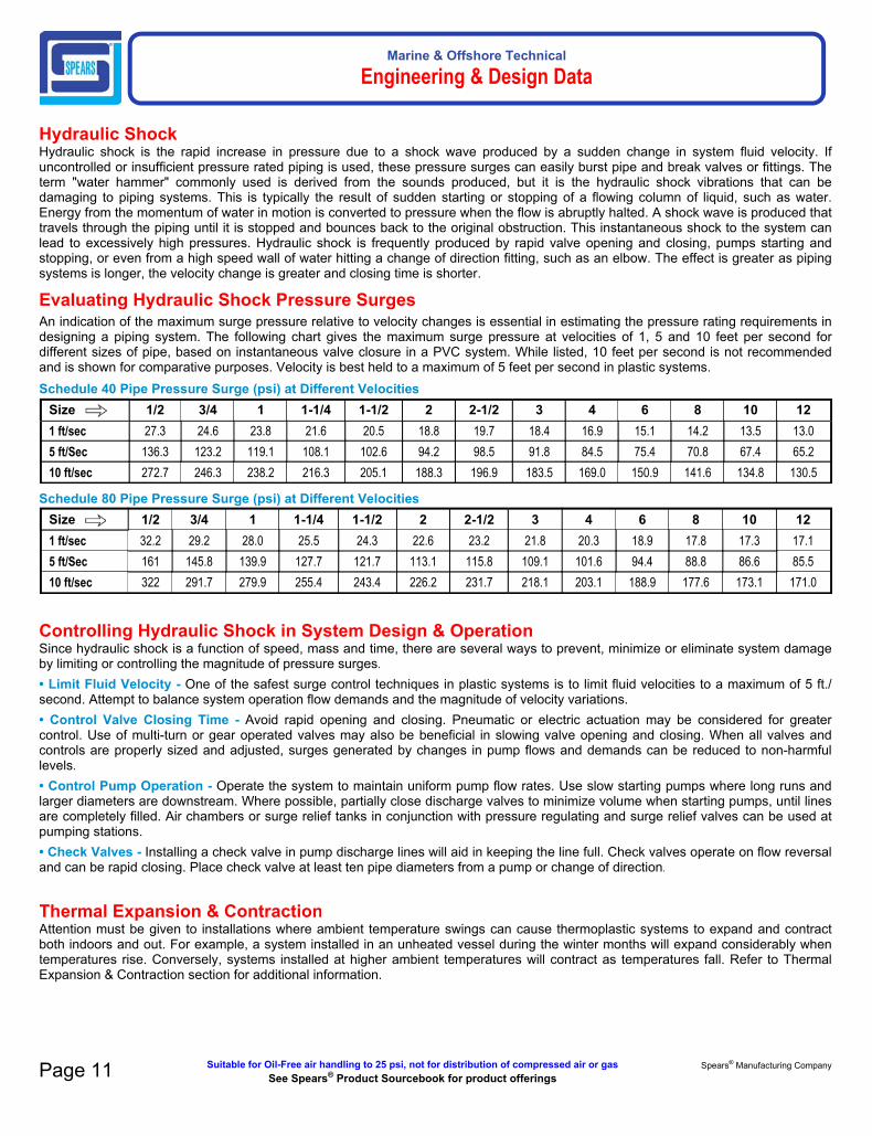
Hydraulic ShockHydraulic shock is the rapid increase in pressure due to a shock wave produced by a sudden change in system fluid velocity. If uncontrolled or insufficient pressure rated piping is used, these pressure surges can easily burst pipe and break valves or fittings. The term "water hammer" commonly used is derived from the sounds produced, but it is the hydraulic shock vibrations that can be damaging to piping systems. This is typically the result of sudden starting or stopping of a flowing column of liquid, such as water. Energy from the momentum of water in motion is converted to pressure when the flow is abruptly halted. A shock wave is produced that travels through the piping until it is stopped and bounces back to the original obstruction. This instantaneous shock to the system can lead to excessively high pressures. Hydraulic shock is frequently produced by rapid valve opening and closing, pumps starting and stopping, or even from a high speed wall of water hitting a change of direction fitting, such as an elbow. The effect is greater as piping systems is longer, the velocity change is greater and closing time is shorter.
Evaluating Hydraulic Shock Pressure SurgesAn indication of the maximum surge pressure relative to velocity changes is essential in estimating the pressure rating requirements in designing a piping system. The following chart gives the maximum surge pressure at velocities of 1, 5 and 10 feet per second for different sizes of pipe, based on instantaneous valve closure in a PVC system. While listed, 10 feet per second is not recommended and is shown for comparative purposes. Velocity is best held to a maximum of 5 feet per second in plastic systems.Schedule 40 Pipe Pressure Surge (psi) at Different Velocities
Size 1/2 3/4 1 1-1/4 1-1/2 2 2-1/2 3 4 6 8 10 121 ft/sec 27.3 24.6 23.8 21.6 20.5 18.8 19.7 18.4 16.9 15.1 14.2 13.5 13.0
5 ft/Sec 136.3 123.2 119.1 108.1 102.6 94.2 98.5 91.8 84.5 75.4 70.8 67.4 65.2
10 ft/sec 272.7 246.3 238.2 216.3 205.1 188.3 196.9 183.5 169.0 150.9 141.6 134.8 130.5
Schedule 80 Pipe Pressure Surge (psi) at Different VelocitiesSize 1/2 3/4 1 1-1/4 1-1/2 2 2-1/2 3 4 6 8 10 121 ft/sec 32.2 29.2 28.0 25.5 24.3 22.6 23.2 21.8 20.3 18.9 17.8 17.3 17.1
5 ft/Sec 161 145.8 139.9 127.7 121.7 113.1 115.8 109.1 101.6 94.4 88.8 86.6 85.5
10 ft/sec 322 291.7 279.9 255.4 243.4 226.2 231.7 218.1 203.1 188.9 177.6 173.1 171.0
Controlling Hydraulic Shock in System Design & OperationSince hydraulic shock is a function of speed, mass and time, there are several ways to prevent, minimize or eliminate system damage by limiting or controlling the magnitude of pressure surges.• Limit Fluid Velocity - One of the safest surge control techniques in plastic systems is to limit fluid velocities to a maximum of 5 ft./ second. Attempt to balance system operation flow demands and the magnitude of velocity variations.• Control Valve Closing Time - Avoid rapid opening and closing. Pneumatic or electric actuation may be considered for greater control. Use of multi-turn or gear operated valves may also be beneficial in slowing valve opening and closing. When all valves and controls are properly sized and adjusted, surges generated by changes in pump flows and demands can be reduced to non-harmful levels.• Control Pump Operation - Operate the system to maintain uniform pump flow rates. Use slow starting pumps where long runs and larger diameters are downstream. Where possible, partially close discharge valves to minimize volume when starting pumps, until lines are completely filled. Air chambers or surge relief tanks in conjunction with pressure regulating and surge relief valves can be used at pumping stations. • Check Valves - Installing a check valve in pump discharge lines will aid in keeping the line full. Check valves operate on flow reversal and can be rapid closing. Place check valve at least ten pipe diameters from a pump or change of direction.
Thermal Expansion & ContractionAttention must be given to installations where ambient temperature swings can cause thermoplastic systems to expand and contract both indoors and out. For example, a system installed in an unheated vessel during the winter months will expand considerably when temperatures rise. Conversely, systems installed at higher ambient temperatures will contract as temperatures fall. Refer to Thermal Expansion & Contraction section for additional information.

Marine & Offshore Technical
Engineering & Design Data
Calculating Linear Movement Caused by Thermal ExpansionThe change in length caused by thermal expansion or contraction can be calculated as follows:
ΔL = 12 yl (ΔT)
Where
ΔL = Expansion or contraction in inchesy = Coefficient of linear expansion of piping material selected l = Length of piping run in feetΔT = (T1 - T2) temperature change °F
Where:
T1 = Maximum system temperature andT2 = System temperature at installation or minimum system temperature
Coefficient of Linear Expansion (y) of Spears® Marine Products (in/in/°F) per ASTM D 696
Pipe Material yCPVC Schedule 40 & Schedule 80 Pressure Pipe 3.2 x 10⁻⁵
Example 1: Calculate the change in length for a 100 foot straight run of 2" Schedule 80 CPVC pipe operating at a temperature of 73°F; installed at 32°F.
ΔL = 12 yl (ΔT)
Where:
ΔL = linear expansion or contraction in inches y = 3.2 x 10⁻⁵ in/in/°F
l = 100ft
ΔT = 41°F (73°F - 32°F)
ΔL = 12 in/ft x 0.000032 in/in/°F x 100 ft x 41°F
ΔL = 1.57"
In this example the piping would expand approximately 1-1/2" in length over a 100 foot straight run once the operating temperature of 73°F was obtained.
Example 2: 100 foot straight run of 2" Schedule 80 CPVC pipe operating temperature 180°F; installed at 80°F
ΔL = 12 yl (ΔT)
Where:
ΔL = Linear expansion or contraction in inches
y = 3.2 x 10⁻⁵ in/in/°F
l = 100 ft
ΔT = 100°F (180°F - 80°F)
ΔL = 12 in/ft x 0.000032 in/in/°F x 100ft x 100°F
ΔL = 3.84"
In this example the piping would expand approximately 4" in length over a 100 foot straight run once the operating temperature of 180°F was obtained.
Compensating for Movement Caused by Thermal Expansion/ContractionThermal expansion/ contraction are usually absorbed by the system at changes of direction. Long, straight runs are more susceptible to measurable movement with changes in temperature and the installation of expansion joints, expansion loops or offsets is required. This will allow the system to absorb expansion/contraction forces without damage.
Once the change in length (ΔL) has been determined, the length of an offset, expansion loop, or bend can be calculated as follows:
Made in the U.S.A. Suitable for Oil-Free air handling to 25 psi, not for distribution of compressed air or gasSee Spears® Product Sourcebook for product offerings Page 12

Marine & Offshore Technical
Engineering & Design Data
Hangers or guides should only be placed in the loop, offset, or change of direction as indicated above, and must not compress or restrict the pipe from axial movement. Piping supports should restrict lateral movement and should direct axial movement into the expansion loop configuration. Do not restrain "change in direction" configurations by butting up against joists, studs, walls or other structures. Use only solvent-cemented connections on straight pipe lengths in combination with 90° elbows to construct the expansion loop, offset or bend. The use of threaded components to construct the loop configuration is not recommended. Expansion loops, offsets, and bends should be installed as nearly as possible at the midpoint between anchors. Concentrated loads such as valves should not be installed in the developed length. Calculated support guide spacing distances for offsets and bends must not exceed recommended hanger support pacing for the maximum anticipated temperature. If that occurs, the distance between anchors will have to be reduced until the support
guide spacing distance is equal to or less than the maximum recommended support spacing distance for the appropriate pipe size at the temperature used.
Example: 2" Schedule 80 CPVC pipe operating temperature 180°F; installed at 80°F where ΔL = 3.84"
ℓ = 3ED (ΔL)2S
ℓ = 3 x 214,000 x 2.375 x 3.842 x 500
ℓ = 76.51"2/5 ℓ = 30.60"1/5 ℓ = 15.30"
2/5
6"min.
6"min.
1/5
Hanger or Guide
15.30"
76.51"
30.60"
Thermal Stress Compressive stress in piping restrained from expanding can damage the piping system and in some cases damage hangers and supports. The amount of stress generated is dependent on the pipe material's coefficient of thermal expansion and its tensile modulus using the following equation:
S = EyΔT
Where
S = Stress induced in the pipe
E = Modulus of Elasticity at maximum system temperature y = Coefficient of
thermal expansion
ΔT = Total temperature change of the system
The stress induced must not exceed the pipe material maximum allowable working stress (fiber stress). Increases in temperature will reduce the allowable stress as shown the table.
Example: 100 ft straight run of 2“ Schedule 80 CPVC pipe operatingtemperature 180°F; installed at 80°F.
ΔL = 12 yl (ΔT) Where:
ΔL = Linear expansion or contraction in inches
y = 3.2 x 10⁻⁵ in/in/°F
l = 100ft
ΔT = 100°F (180°F - 80°F)
ΔL = 12 in/ft x 0.000032 in/in/°F x 100 foot x 100°F
ΔL = 3.84"
The piping would expand approximately 4" in length in a 100 ft straight run
The equation for determining induced stress can then be used:
S = EyΔT
Where:
S = Stress induced in the pipe
E = Modulus of Elasticity at 180°F = 214,000
y = Coefficient of thermal expansion = 3.2 x 10⁻⁵ in./in./°F
ΔT = Total temperature change of the system = 100°F
S = 214,000 x .000032 x 100
S = 685 psi
From chart, maximum allowable stress for CPVC at 180°F is 500 psi; Stress generated from this expansion in a restrained piping system exceeds the maximum allowable stress and will result in failure of the piping, unless compensation is made for thermal expansion.
Maximum Allowable Working (Fiber) Stress and Tensile Modulus at Various Temperatures
Temp (°F)Maximum Allowable
Working (Fiber) Stress, psi
Tensile Modulus of Elasticity, psi
CPVC
73 2,000 364,000
90 1,820 349,000
100 1,640 339,000
110 1,500 328,000
120 1,300 316,000
140 1,000 290,000
160 750 262,000
180 500 214,000
200 400 135,000
Page 13 Suitable for Oil-Free air handling to 25 psi, not for distribution of compressed air or gas Spears® Manufacturing CompanySee Spears® Product Sourcebook for product offerings

Marine & Offshore Technical
Engineering & Design Data
Made in the U.S.A. Suitable for Oil-Free air handling to 25 psi, not for distribution of compressed air or gasSee Spears® Product Sourcebook for product offerings Page 14
Temperature LimitationsCPVCThe maximum operating temperature for CPVC Schedule 40/80 marine pipe is 200°F. As temperatures increase, impact strength typically increases while tensile strength and pipe stiffness decrease resulting in reduced applicable pressure ratings. Physical properties of CPVC pipe are generally specified at 73°F per applicable ASTM material test standards. The maximum allowable pressure at elevated temperatures is determined by multiplying the 73°F pressure rating by the applicable material de-rating factor for the elevated use temperature shown in the following chart. See Marine Pipe General Information for pipe pressure ratings @ 73°F.
De-Rating FactorsCPVC Pipe
Temp(°F)
WorkingDe-Rating
Factor73-80 1.00
90 0.91
100 0.82
110 0.72
120 0.65
130 0.57
140 0.50
150 0.42
160 0.40
170 0.29
180 0.25
200 0.20
Appropriate temperature de-rating factors must be applied at temperatures other than 73°F based on the material selected.
Multiply the collapse pressure rating of the selected pipe at 73°F, by the appropriate de-rating factor to determine the collapse pressure rating of the pipe at the elevated temperature chosen.
WeatherabilityWhen rigid CPVC marine pipe is exposed to UV radiation from sunlight, the following conditions have been noted:
• A color change, slight increase in tensile strength, slight increase in modulus of tensile elasticity, and a slight decrease in impact strength may occur.
• Material directly exposed to UV radiation results in extremely shallow penetration depths (frequently less than 0.001 inch).
• The effects of UV exposure do not continue when exposure to UV is terminated.
• The effects of UV exposure do not penetrate even thin shields such as paint coatings, or wrapping.
It is recommended that CPVC piping products exposed to the direct affects of sunlight be painted with a light colored acrylic or latex paint that is chemically compatible with the CPVC products. Check with paint manufacture for compatibility. Oil-based paints should NOT be used.
Additional consideration should be given to the effects of expansion/contraction caused by heat absorption from sunlight in outdoor applications.

Marine & Offshore Technical
Installation
Installation Training & InformationASME B31.3 installer training courses are available from Spears® at no cost. If you would like to arrange for training or have any questions about the safe installation and use of this system, contact Spears® Manufacturing Company, 15853 Olden Street, Sylmar, CA 91342 USA, Telephone (818) 364-1611.
Handling & StorageSpears® marine products are packaged and shipped with care to avoid damage. Pipe and fittings should be stored and protected from direct exposure to sunlight. All pipe and accessories should be stored above ground and fully supported so as not to bend or excessively deflect under its own weight. Proper stacking can result in instability that may result in pipe damage or personnel injury.Use care when transporting and storing the product to prevent damage. Piping products should not be dropped or have objects dropped on them. Do not drag pipe over articles or across the ground and do not subject pipe to external loads or over stacking. If extended storage in direct sunlight is expected, pipe should be covered with an opaque material while permitting adequate air circulation above and around the pipe as required to prevent excessive heat accumulation.Spears® marine products should not be stored or installed close to heat-producing sources. CPVC storage should not exceed 210°F. Handling techniques for CPVC marine pipe considered acceptable at warm temperatures may be unacceptable at very cold temperatures. When handling pipe in cold weather, consideration must be given to its lower impact strength. In subfreezing temperatures, extra caution in handling must be taken to prevent impact damage. All CPVC marine pipe should be inspected for any scratches, splits or gouges before use. Damaged sections must be cut out and discarded.
Plastic Piping ToolsBasic Tools used with Plastic PipingUse tools that have been specifically designed for use with thermoplastic pipe and fittings when installing. A variety of tools that are designed for cutting, beveling, and assembling plastic pipe and fittings, are readily available through local wholesale supply houses dealing in plastic pipe and fittings.•Warning Tools normally used with metal piping systems, such as hacksaws, water pump pliers, pipe wrenches, etc., can cause damage to plastic pipe and fittings. Visible and hidden fractures, scoring or gouging of material, and over tightening of plastic threaded connections are some of the common problems resulting from the use of incorrect tools and procedures.
Pipe CuttersPipe must be square-cut to allow for the proper joining of pipe end and the fitting socket bottom. Wheel type pipe cutters designed for plastic pipe provides easy and clean cuts on smaller pipe sizes. Care should be used with similar ratchet-type cutters to avoid damage to pipe. A slightly raised edge left on the outside of the pipe end after cutting with either device must be removed.
Pipe Cutters for Large Diameter PipeBlade cutters made for use with large diameter plastic pipe are easy to adjust and operate for square, burr-less cuts. Blades with carbide edges will provide longer life. With one style blade cutter, pipe ends may also be beveled for solvent joints while being cut by using an optional bevel tool in place of one cutter blade.
Hand SawsA miter box or similar guide can be used with a fine-toothed saw blade (16 to 18 teeth per inch) having little or no set (maximum 0.025 inch).
Power SawsPower saws are quite useful in operations where a large quantity of pipe is being cut. Blades designed for plastic pipe MUST be used. A cutting speed of 6,000 RPM, using ordinary hand pressure is recommended.
Pipe Beveling ToolsPower beveling tools, as well as hand beveling tools designed for use with plastic pipe are available. Pipe ends must be beveled (chamfered) to allow easy insertion of the pipe into the fitting and to help spread solvent cement and to prevent scraping cement from the inside of the fitting socket. A recommended bevel of 1/16" to 3/32" at a 10° to 15° angle can be achieved using a plastic pipe beveling tool, but can also be accomplished using a file designed for use on plastic.
Deburring ToolsSpecial plastic pipe deburring tools remove burrs from pipe ends quickly and efficiently. All burrs must be removed from the inside, as well as the outside, of the pipe ends to properly spread solvent cement when joining pipe and fitting.
Strap WrenchesStrap wrenches with nylon straps treated for slip resistance and designed for use with plastic pipe provide gripping power for turning without scratching or deforming the pipe.
Chain VisesChain vises can be used to hold pipe. Vises made with jaws engineered for use with plastic pipe provide holding power without damage to the pipe.
Pullers & Joining DevicesPipe and fitting pullers are available for joining large diameter plastic pipe and fittings. These tools are designed to allow the pipe to be inserted to the proper insertion depth, maintain proper alignment during assembly, and hold freshly solvent-cemented connections to prevent the fitting from backing-off until the initial set time is achieved.
Joining Methods - SolventCement WeldingSolvent cement welding is the most widely used joining method for PVC and CPVC pipe and fittings. Other methods such as threads, flanges and groove adapters can also be used. These are specifically useful where it is anticipated that the joint will have to be disassembled in the future.
Solvent Cement Safety PrecautionsSolvent cement products are flammable and contain chemical solvents. Appropriate safety precautions must be taken BEFORE APPLYING PRIMER AND CEMENT. Read the cement can label!
•CAUTION
Virtually all solvent cements and primers for plastic pipe are flammable and should not be used or stored near heat, spark or open flames. Do not smoke during use. Eliminate all ignition sources. Primer should be stored in closed containers in the shade at temperatures between 40°F and 110°F; CPVC cement at temperatures between 40°F and 90°F. Use of a can with applicator attached to its lid is recommended. Verify expiration dates stamped on cements and primers prior to use.Avoid breathing vapors. They should be used only with adequate ventilation. Explosion-proof general mechanical ventilation is recommended. In confined or partially enclosed areas, a ventilating device should be used. Containers should be kept tightly closed when not in use, and covered as much as possible when in use.
Page 15 Suitable for Oil-Free air handling to 25 psi, not for distribution of compressed air or gas Spears® Manufacturing CompanySee Spears® Product Sourcebook for product offerings

Marine & Offshore Technical
Installation
Avoid contact with skin and eyes. May be absorbed through the skin; wearing PVA coated protective gloves and an impervious apron are recommended. May cause eye injury. Use eye protection and avoid eye contact. In case of contact, flush with plenty of water for 15 minutes. If irritation persists, get medical attention. If swallowed, call a physician immediately and follow precautionary statement given on side panel of cement container. Keep out of reach of children.
Refer to Solvent Cement Safety Data Sheet (SDS)
Use Caution with Welding Torches or other equipment where sparks might be involved at construction sites where plastic pipe has recently been solvent welded. Flammable vapors from cemented joints can stay within a piping system for some time. In all cases, lines should be flushed and purged to remove solvent vapors before welding.
Use Caution with Calcium Hypochlorite. Do not use a dry granular calcium hypochlorite as a disinfecting material for water purification in potable water piping systems. Granules or pellets of calcium hypochlorite (including their vapors) may react violently with solvent cements and primers if a water solution is not used. Chlorinated water solutions are nonvolatile and may be pumped into the piping system. Dry granular calcium hypochlorite should not be stored or used near solvent cements or primers.
Solvent Cement and Primer SpillsProtect work areas prior to starting by using drop cloths in the event of a spill. Accidental spills should be wiped up immediately before the cement sets. Cement and/or primer spills can cause irreparable damage depending on the type of surface affected. Consult the manufacturer of the affected surface for possible suggestions.
Basic Solvent Cement JointsThe following is a general description of basic techniques used to make solvent cement joints. Adjustments will need to be made to method and tools used according to size of piping, but the same principles apply. Additional guidance can be found in ASTM D 2855, Standard Practice for Making Solvent-Cemented Joints with Poly (Vinyl Chloride) (PVC) Pipe and Fittings. Important: Installers should verify that they can make satisfactory joints under varying conditions and should receive training in installation and safety procedures.
Spears® offers Bonder Qualification Training (ASME B31.3) as required by the U.S. Coast Guard and Classification Societies. Contact Spears® for more information: (818) 364-1611.
To consistently make good joints in PVC and CPVC piping products, the following should be carefully understood:
1. The joining surfaces of pipe and fitting must be softened and made semi-fluid.
2. Sufficient cement must be applied to fill the gap between pipe and fitting.
3. Assembly of pipe and fittings must be made while the surfaces are still wet and fluid.
4. Joint strength develops as the cement dries (cures). In the tight part of the joint (interference area) the surfaces will fuse together; in the loose part the cement will bond to both surfaces.
Cutting the PipeCPVC pipe can be cut easily with a ratchet cutter, wheel-type plastic pipe cutter (NOTE: be sure to remove any raised ridge produced by wheel cutters), a power saw, or any other fine-tooth saw. It is important that the cutting tools being used are designed for plastic pipe. To ensure that the pipe is cut square, use a miter box when cutting with a saw. Cutting pipe as square as possible provides the maximum bonding surface area.
Be careful not to split the tube if using a ratchet-type cutter, especially in temperatures below 50°F. If any damage or cracking is evident, cut off at least 2" of the pipe beyond any visible crack.
Deburring & BevelingBurrs and filings can prevent contact between the tube and the fitting during assembly and must be removed from the outside and the inside of the pipe. A deburring/chamfering tool (or file) is suitable for this purpose:
Burrs Being Removed from Outside & InsideA slight bevel (chamfer) must be placed at the outsided end of the pipe to ease the entry of the tube into the socket and minimize the chance of cement being wiped off the fitting:
Bevel Outside End
Fitting & Joining Preparation1. Using a clean, dry rag, wipe any loose dirt and moisture from the fitting's socket and pipe end. Moisture can slow the cure time, and at this stage of assembly, excessive moisture can reduce joint strength.2. Check the dry fit of the pipe and fitting. The pipe should enter the fitting's socket easily 1/3 - 2/3 of the way (interference fit) , or at least have interference between pipe and fitting bottom (net fit). DO NOT use any components that appear irregular or do not fit properly. Contact Spears® regarding any questions about usability.3. Measure socket depth and mark on pipe for reference during cement application.4. It is advisable to additionally mark pipe and fitting for alignment orientation position, especially with larger fittings.
Made in the U.S.A. Suitable for Oil-Free air handling to 25 psi, not for distribution of compressed air or gasSee Spears® Product Sourcebook for product offerings Page 16

Marine & Offshore Technical
Installation
Solvent Cementing AssemblyVerify the expiration date located on the solvent cement can. The cement can be used for a period of 2 years from the date stamped on the can. When cementing pipe and fittings in extremely cold temperatures, make sure the cement has not "JELLED." Jelled or expired cement must be discarded in an environmentally friendly fashion, in accordance with local regulations. To prolong the life of solvent cement, keep the containers tightly closed when not in use, and cover the container as much as possible during use. If an unopened solvent cement container is subjected to freezing temperatures, the cement may become extremely thick. Place the closed container in a room temperature area where, after a short time period, the cement will return to a usable condition. DO NOTattempt to heat solvent cement. The cement must be applied when the pipe and fittings are clean and free from any moisture and debris.
Primer Use - Softening of pipe and fitting joining surfaces can be achieved by the cement itself or by using a suitable primer. A primer will usually penetrate and soften the surfaces more quickly than the cement alone. The primer can be used for a period of 3 years from the date stamped on the can.
Apply Primer - USING AN APPLICATOR THAT IS AT LEAST 1/2 THE SIZE OF THE PIPE DIAMETER, vigorously scrub joining surface of fitting, of pipe and then again of fitting. Work quickly to apply 2-3 coats in this manner. SOLVENT CEMENT SHOULD THEN BE APPLIED WHILE PRIMER IS STILL WET.
Apply Solvent Cement - USING AN APPLICATOR THAT IS AT LEAST 1/2 THE SIZE OF THE PIPE DIAMETER, WORK THE CEMENT INTO THE JOINING SURFACES USING A CONTINUOUS, CIRCULAR MOTION.
Use sufficient cement, but avoid puddling the cement on or within the fitting and pipe. Puddled cement causes excess softening and damage to the CPVC material. If interference fit was at the bottom of the socket, use extra cement and make a 2nd application to pipe. WORK QUICKLY SO THAT PIPE AND FITTING CAN BE JOINED WHILE CEMENT IS STILL WET.
Apply the cement in the sequence pictured below:
1. Apply a coat to the pipe to depth of fitting socketWork the cement into the joining surfaces using a continuous, circular motion.
2. Apply a medium coat to the fitting socketAvoid puddling the cement in the sockets and avoid getting cement in other sockets or threaded connections.3. Apply a second coat to the pipe end for sizes 1-1/4 inch and larger joints, or if interference fit was at socket bottom during dry-fit.
Assemble JointImmediately insert pipe into the fitting socket while rotating the pipe 1/4 turn. Align the fitting in the proper orientation at this time. Make sure the pipe bottoms out at the fitting's stop. Hold the assembly for at least 30 seconds to ensure initial bonding. Tapered pipe sockets can result in pipe backing out of the joint if not held under constant pressure A bead of cement must be present around the pipe and fitting juncture. If this bead is not continuous around the socket's shoulder, insufficient cement was applied and the joint must be disassembled or cut out and replaced.
Any cement, in excess of the bead, can be wiped off with a dry, clean rag.
Set and Cure TimesSET TIME: The initial set time is the recommended waiting period before handling newly assembled joints. After initial set, the joints will withstand the stresses of normal installation. However, a badly misaligned installation will cause excessive stresses in the joint, pipe and fittings.
CURE TIME: The cure time is the recommended waiting period before pressurizing newly assembled joints.
The following basic guidelines should be used:
• The set and cure times for solvent cement depend on pipe size, temperature, relative humidity, and tightness of fit. Drying time is faster for drier environments, smaller pipe sizes, high temperatures, and tighter fits.
• Special care must be taken when assembling products in low temperatures (below 40°F) or high temperatures (above 80°F).
• Extra set and handling times must be allowed in colder temperatures. When cementing pipe and fittings in cold temperatures, make sure the cement has not "JELLED." Jelled cement must be discarded.
• In higher temperatures, make sure both surfaces to be joined are still wet with cement during assembly.
• The assembly must be allowed an initial set, without any stress on the joint
• Following the initial set period, the assembly can be handled carefully by avoiding stress on the joint.
Average Set TimesTemp. Range
Pipe Sizes 1/2"- 1-1/4"
Pipe Sizes 1-1/2"- 2"
Pipe Sizes 2-1/2"- 8"
Pipe Sizes10"- 12"
60° - 100°F 2 Min. 5 Min. 30 Min. 2 Hrs.
40° - 60°F 5 Min. 10 Min. 2 Hrs. 8 Hrs.
0° - 40°F 10 Min. 15 Min. 12 Hrs. 24 Hrs.
Page 17 Suitable for Oil-Free air handling to 25 psi, not for distribution of compressed air or gas Spears® Manufacturing CompanySee Spears® Product Sourcebook for product offerings

Marine & Offshore Technical
Installation
Special Considerations for Working with Solvent Cement WeldingHandling of CementKeep Marine-24 cement containers covered while not in use. Marine-24 Cement with the lid left off can become thick and viscous, or gel like. This condition is typically a result of tetrahydrofuran (THF) solvent evaporation and the cement is useless. Do not try to restore the Marine-24 cement by stirring in a thinner. Smaller containers of Marine-24 cement are recommended to be used, especially in warm or hot weather. Prior to opening cans of Marine-24 cement, shake vigorously to properly mix resin and solvents. Solvents contained in Marine-24 cement are highly flammable and should not be used near an open flame. The area in which the Marine-24 cement is being used should be well ventilated, and prolonged breathing of the fumes should be avoided, as well as contact with the skin or eyes. Verify the expiration dates stamped on the Marine-24 cement and primers prior to use.
CEMENT AND PRIMER SHELF LIFESpears® Products Shelf Life Spears® Products Shelf Life
Primers / Cleaners 3 years CPVC Solvent Cement 2 years
Hot Weather UseProblems can be avoided when solvent cementing in 95°F or higher temperatures by taking a few special precautions. Solvent cements evaporate faster at elevated temperatures and can dry out prematurely. This is especially true when there is a hot wind blowing. Dry cement on pipe or fitting socket prior to assembly will not bond. If the pipe has been in direct sunlight for any length of time, surface temperatures may be 20°F to 30°F above air temperature. Solvents attack these hot surfaces faster, deeper and dry out quicker. As a result, it is very important to avoid puddling inside sockets, assemble immediately while wet and to wipe off excess cement at the joint exterior.
Tips for Solvent Cementing in High Temperatures:
1. Store solvent cements in a cool or shaded area prior to use.
2. If possible, store the fittings and pipe, or at least the ends to be solvent welded, in a shady area before cementing.
3. Cool surfaces to be joined by wiping with a damp rag. HOWEVER, be sure that surfaces are dry prior to applying solvent cement.
4. Try to do the solvent cementing in cooler morning hours.
5. Make sure that both surfaces to be joined are still wet with cement when putting them together.
Cold Weather UseMarine-24 solvent cement and PRIM70 primers have excellent cold weather stability and are formulated to have well balanced drying characteristics even in subfreezing temperatures. Good solvent cemented joints can be made in very cold conditions provided proper care and a little common sense are used. In cold weather, solvents penetrate and soften surfaces more slowly than in warm weather. The plastic is also more resistant to solvent penetration, therefore, it becomes more important to pre-soften surfaces. A longer cure time is necessary due to slower evaporation.
Tips for Solvent Cementing in Cold Temperatures:
1. Prefabricate as much of the system as possible in a heated work area.
2. Store cements in a warmer area when not in use and make sure they remain fluid.
3. Take special care to remove moisture, including ice and snow.
4. Use special care to ensure joining surfaces are adequately softened; more than one application may be necessary.
5. Allow a longer cure period before the system is used.
Effects of Tolerances and FitsCPVC marine pipe and fittings are manufactured to applicable ASTM Standards to produce an interference fit when assembled. However, minimum and maximum allowable tolerances permitted for pipe and fitting can result in variations. For example, fitting with the maximum diameter and the pipe with the minimum diameter, may result in a loose fit. Applying two coats of solvent cement will help assure a good joint. Conversely, if the pipe diameter is on the maximum side and the fitting on the minimum side, the interference may be too great and sanding of the pipe O.D. may be necessary to permit entrance.
Always check dry fits prior to making a joint. If fit is loose, multiple coats and use of an extra heavy bodied cement may be required. Mating components should be checked to assure that tolerances and engagements are compatible (see preceding Basic Solvent Cement Joints instructions). Inspect all pipe and fittings for damage or irregularities. Do not use any components that appear irregular or do not fit properly. Contact the appropriate manufacturer of the product in question to determine usability.
Made in the U.S.A. Suitable for Oil-Free air handling to 25 psi, not for distribution of compressed air or gasSee Spears® Product Sourcebook for product offerings Page 18
Average Cure Times
Relative Humidity
60% or Less*
Pipe Sizes 1/2" - 1-1/4"
Pipe Sizes 1-1/2" - 2"
Pipe Sizes 2-1/2" - 8"
Pipe Sizes 10" - 12"
Temperature Range During Assembly and Cure Periods
Up to 160 psi
Above160 to370 psi
Up to160 psi
Above 160 to315 psi
Up to 160 psi Above 160 to 315 psi Up to 100 psi
60° - 100°F 15 Min. 6 Hrs. 30 Min. 12 Hrs. 1-1/2 Hrs. 24 Hrs. 48 Hrs.
40° - 60°F 20 Min. 12 Hrs. 45 Min. 24 Hrs. 4 Hrs. 48 Hrs. 96 Hrs.
0° - 40°F 30 Min. 48 Hrs. 1 Hr. 96 Hrs. 72 Hrs. 8 Days 8 days
•NOTE In damp or humid weather allow 50% more cure time. The cure schedules shown are suggested as guides only. They are based on laboratory test data, and should not be taken to be the recommendations of all cement manufacturers. Individual solvent cement manufacturer's recommendations for the particular cement being used should be followed.

Marine & Offshore Technical
Installation
Large Diameter PipeBasic Solvent Cement Joint instructions apply to all sizes of pipe, but when making joints larger than 4", the use of two persons is recommended to properly apply cement and immediately assemble the joint while the cemented surfaces are still wet. Alignment of large diameter pipe and fittings during joining is critical since there is a greater potential for movement in the upper portion of a tapered socket that can result in misalignment. Special tools are commercially available for joining large diameter pipe.
Be sure to use an appropriate size roller applicator with large diameter pipe, along with Marine-24 CPVC heavy bodied cement. Marine-24 cement has increased gap filling capability and allow somewhat longer assembly time. However, applications of heavy coats of solvent cement and speed in making the joint is important. Under a damp or wet condition, solvent cement may absorb some moisture. Excessive moisture can slow down the cure and reduce joint strength. Spears® Marine-24 heavy body cement is excellent for joining large diameter pipe.
Estimated Quantities of Solvent CementA variety of conditions can affect the amount of solvent cement required for making reliable joints. These include pipe size, tolerances, socket depths as well as installation conditions and type of cement used. Fitting sockets are tapered for proper assembly, which produces a slight gap at the socket entrance when installed with pipe. It is best to use liberal amounts of solvent cement since insufficient cement use is one of the most common reasons for joint failure. The following information on cement usage is a recommendation only and other factors or unanticipated conditions may be encountered. Quantities are based on use with average socket lengths of Spears® molded and fabricated fittings.
Standard Pipe Joints
Fitting Size (in.)
Joints per Quart
Jointsper Gallon
1/2 300 1200
3/4 200 800
1 125 500
1-1/4 140 560
1-1/2 90 360
2 60 240
2-1/2 50 200
3 40 160
4 30 120
6 10 40
8 5 20
10 2-3 4-6
12 1-2 2-4
Supplemental Information on Solvent CementingApplicatorsA wide variety of daubers, brushes, and rollers are available. For proper solvent cement welding of pipe and fittings, the cement applicator must be no less than half the size of the pipe. Sufficient cement cannot be applied using daubers attached to the cement can lid on large diameter products (> 3"dia.) The following chart shows a variety of Spears® applicator sizes for use on different pipe diameters.
SPEARS® APPLICATOR SELECTION GUIDEFor proper solvent cement welding of pipe and fittings, the cement
applicator must be no less than half the size of the pipe
DAUBERSPipe Diameters
1/2" 3/4" 1" 1-1/4" 1-1/2" 2"
3/8" Dauber • •
1/2" Dauber • •
3/4" Dauber • •
1-1/4" Dauber •
ROLLERS & SWABS SIZE FOR PIPE DIAMETERS
3020 3" Roller 3" - 6"
6020 4" Roller 3" - 8"
7020 7" Roller 6" +
5520 4" Roller 6" +
6520 6" Roller 6" +
4020 4" Swab 6" +
5020 4" Swab 3" - 8"
4520 4" Swab 6" +
CleanersCleaners can be used to remove dirt, oil and grease from the bonding surfaces of CPVC pipe and fittings. Use of a cleaner is recommended before priming of pipe and fittings.
PrimersThe use of Primer is necessary to penetrate and dissolve the surface of the pipe and fitting prior to the application of cement. Primer must be applied to both the pipe and fittings. Apply multiple coats of primer to the fitting socket and to the outside of the pipe ensuring that the entire surface is wet. Solvent cement must be applied immediately after primer while the surfaces are still tacky.
Solvent CementsSolvent cements are typically formulated using tetrahydrofuran (THF). When properly applied, this solvent dissolves the mating surfaces of the pipe and fittings. Cyclohexanone is a typical retardant used to slow the rate of solvent evaporation. Immediate joining of the wet mating surfaces in one minute or less is essential to eliminate dry spots that will not bond. The bond interface is strongest at the area of interference fit where the softened semi-fluid surfaces of the pipe and fitting chemically fuse. Plastic resin fillers (dissolved CPVC) in the cement fill the gaps between pipe and fitting.
Page 19 Suitable for Oil-Free air handling to 25 psi, not for distribution of compressed air or gas Spears® Manufacturing CompanySee Spears® Product Sourcebook for product offerings

Marine & Offshore Technical
Installation
Joining Method - Threaded ConnectionsThreaded connections require the application of a thread sealant that is compatible with CPVC material. Spears® recommends the use of Spears® Blue 75™ Thread Sealant.
CAUTION - Use only thread sealants recommended for CPVC plastic. Other joint compounds or pastes may contain substances that could cause stress cracks in CPVC materials.
Apply sealant to the male threads only. Make sure all threads are covered. DO NOT clog the waterway with excess sealant. If PTFE tape must be used, Spears® recommends a thickness of at least .0035" that meets or exceeds military specification, A-A-58092 (formerly MIL-T-27730A). DO NOT use a combination of tape and thread paste on the same joint. Apply PTFE tape in the direction of the threads by starting with the first full thread and continuing over the entire thread length. Make sure all threads are covered. Generally, 2 - 3 wraps are sufficient to produce a watertight connection
DO NOT over-torque any threaded connections. Generally, one to two turns beyond finger-tight are required for a threaded connection. Use a smooth-jawed wrench or strap wrench when installing threaded connections.
Threading PipeCPVC marine schedule 80 pipe can be threaded using either standard hand pipe stocks or power-operated equipment. Since rigid CPVC plastic pipe has the same outside diameter as standard steel pipe in comparable sizes, standard steel pipe taps and dies can be used. A cut thread or deep scratch results in a stress concentration point. As a result, only Schedule 80 pipe should be threaded. A 50% pressure de-rating is applied to threaded pipe to compensate for this. DO NOT thread Schedule 40 pipe. For optimum results in threading, use new taps and dies; but in any case, they should be cleaned and sharpened and in good condition. Power threading machines should be fitted with dies having a 5° negative front rake and ground especially for this type of pipe; tapered guide sleeves are not required. For hand stocks the dies should have a negative front rake of 5° to 10°. Dies which have been designed for use on brass or copper pipes may be used successfully. Carboloy dies give longer service. (Taps should be ground with a 0° to 10° negative rake, depending upon the size and pitch of the thread. Die chasers should have a 33° chamfer on the lead; a 10° front or negative rake; and a 5° rake on the back or relief edge).
Self-opening die heads and collapsible taps, power threading machines and a slight chamfer to lead the tap or dies will speed production; however, taps and dies should not be driven at high speeds or with heavy pressure.
A tapered plug should be inserted into the pipe when threading, to hold the pipe round and to prevent the die from distorting and digging into the pipe wall. This ensures uniform thread depth all the way around. Pipe for threading should be held in a suitable pipe vise, but saw-tooth jaws should not be used. Flanges and close nipples should be threaded in jigs or tapping fixtures. To prevent crushing or scoring the pipe, some type of protective wrap, such as canvas, emery paper, or a light metal sleeve should be used; rounding of chuck jaws will also be helpful. Rigid CPVC plastic pipe should be threaded without use of lubricants. Standard cutting oils can cause stress cracking in plastics and should not be used. Water-soluble oil or plain water is recommended. Degreasing with any solvents is not recommended, nor should solvents be used in any cleanup. Always clear cuttings from the die.
DO NOT OVER THREAD - To obtain a tight, leak proof joint, the thread dimensions shown in the table should be used. If pipe is over threaded, fittings cannot be run on far enough to make a tight seal.
American National Standards Institute Code B1.20.1 covers dimensions and tolerances for tapered pipe threads. Only Schedule 80 pipe should be threaded.
Angle between sides of thread is 60 degrees. Taper of thread, on diameter, is 3/4 inch per foot. The basic thread depth is 0.8 x pitch of thread and the crest and root are truncated an amount equal to 0.033 x pitch, excepting 8 threads per inch which have a basic depth of 0.778 x pitch and are truncated 0.045 x pitch at the crest and 0.033 x pitch at the root.
Made in the U.S.A. Suitable for Oil-Free air handling to 25 psi, not for distribution of compressed air or gasSee Spears® Product Sourcebook for product offerings Page 20
PIPE THREADSNominalSize (in.)
(Max.) (In.)
OutsideDiameter
(in.)D
Number ofThreadsPer Inch
NormalEngagementBy Hand (in.)
C
Lengthof EffectiveThread (in.)
A
Total Length:End of pipe to
vanish point (in.)B
Pitch Diameterat end of Internal
Thread (in.)E
Depth ofThread
(Max.) (in.)
1/2 0.840 14 0.320 0.5337 0.7815 0.77843 0.05714
3/4 1.050 14 0.339 0.5457 0.7935 0.98887 0.05714
1 1.315 11-1/2 0.400 0.6828 0.9845 1.23863 0.06957
1-1/4 1.660 11-1/2 0.420 0.7068 1.0085 1.58338 0.06957
1-1/2 1.900 11-1/2 0.420 0.7235 1.0252 1.82234 0.06957
2 2.375 11-1/2 0.436 0.7565 1.0582 2.29627 0.06957
2-1/2 2.875 8 0.682 1.1375 1.5712 2.76216 0.10000
3 3.500 8 0.766 1.2000 1.6337 3.38850 0.10000
4 4.500 8 0.844 1.3000 1.7337 4.38713 0.10000
6 6.625 8 0.958 1.5125 1.9462 6.50597 0.10000

Marine & Offshore Technical
Installation
Joining Method - Flanged ConnectionsPVC and CPVC flanges are available in several designs, including solid one- piece flanges, two-piece Van Stone style flanges featuring a movable ring for bolt alignment, and blind flanges for capping off a piping run. Marine flanges are available in socket, spigot and threaded configurations and are coupling devices designed for joining IPS (Iron Pipe Size) plastic piping systems where frequent disassembly may be required. Flanges can be used as a transitional fitting for joining plastic to metal piping systems, and for connection to other flanged type valves and equipment. A flat gasket is used between flanges to form a water-tight seal. Proper gasket material should be selected for fluid compatibility. Most plastic flanges carry a maximum working pressure rating of 150 psi non-shock for water at 73° F (23° C). Pressure ratings may vary according to size and flange construction. Consult flange manufacturer.
GasketsSelect appropriate size and bolt pattern gasket. Full faced, 1/8" thick elastomer flat gaskets with a Shore "A" Durometer of approximately 70 (±5) are recommended. A full-face flat gasket should cover the entire flange face but not obstruct the waterway. Verify that the gasket material is chemically compatible for use with the application fluid conveyed through the system.
Low Torque Double ConvexDesign Full Face GasketsLow torque-style gaskets require up to 50% less torque to achieve a leak-free seal. When using this type of gasket in combination with Spears® flanges be sure to follow the torque recommendations from the low torque gasket manufacturer. Over-torquing a low torque gasket may cause damage to the flange.DO NOT USE: Spiral wound, ring, kammprofile, corrugated metal gaskets, non- asbestos or cork gaskets.
Bolt Patterns & Fastener SelectionMost PVC and CPVC flanges are produced with ANSI B16.5 bolt patterns for Class 125/150 flanges. Optional Class 300 bolt patterns (NOT a 300psi rating), certain ANSI/Metric dual pattern flanges, and metric bolt patterns can be produced. Proper bolt size, number and length should be selected for the specific flanges and equipment being assembled. Bolt length requirements will vary according to the flange or equipment manufacturer. Spears® offers bolt packs (HK series) for use with Spears® flange to flange assemblies.Bolts: To ensure minimal friction use a zinc-plated grade 5 bolt or stud of suitable length in accordance with ASME B18.2.1 to accommodate (2) flange thicknesses, (2) washers and (1) 1/8" full face gasket thickness.Nuts: Use grade 5 zinc-plated hex nuts in accordance with ASME B18.2.2. Orient nut so flat side contacts flange surface.Washers: Always use (2) wide flat washers for each bolt, one under the bolt head and one under the nut. Use flat, zinc-plated steel (Plate type) grade 5 washers in accordance with ASME B18.21.1 (Do not use thin "fender" washers).
Important: Stainless steel fasteners can be used. Be sure to use a compatible anti-seize lubricant to eliminate galling.
Bolt Preparation & TorqueThreads should be cleaned and well lubricated. Apply a liberal amount of a chemically compatible copper-graphite anti-seize bolt lubricant to each bolt thread. Use a lubricant with a K factor (nut factor) of 0.15. Adequate application of thread lubricant is indicated by lubricant extrusion from the threaded joint as the nut is tightened. (WARNING: Use only bolt lubricants compatible with PVC or CPVC material).
Hand tighten all nuts until they are snug prior to torquing flange bolts. Using a calibrated torque wrench accurate to within ± 1ft-lb. tighten each bolt in approximately 5 ft-lb. increments using a 180° opposing sequence. Follow the
numbers sequence engraved next to each Spears® flange bolt hole or consult Torque Sequence - Table 1 information. Actual field conditions may require variations in these recommendations. UNNECESSARY OVER-TORQUING WILL DAMAGE THE FLANGE. Torque should always be applied in approximately 5 ft-lb. increments using a 180° opposing sequence.
Flange Make-upFollow proper solvent cementing and/or threaded component procedures as applicable to join the flange to the pipe. Once a flange is joined to pipe, the method for joining two flanges is as follows:
1. Piping runs joined to the flanges must be installed in a straight-line position to the flange to avoid stress at the flange due to misalignment. Piping must also be secured and supported to prevent lateral movement which can create stress and damage the flange.
Proper Alignment Improper Alignment
2. With full face gasket in place, align the bolt holes of the mating flanges by rotating the ring into position with a Van Stone style flange or by rotating the pipe assembly with a one-piece flange installed.
3. Insert all bolts, washers (two standard flat washers per bolt), and nuts.
4. Make sure the faces of the mating surfaces are flush against gasket prior to bolting down the flanges.
5. Tighten all nuts by hand until they are snug. Establish uniform pressure over the flange face by tightening the bolts in 5 ft.-lb. increments according to the torque values shown in the following table using a 180° opposing sequence. Make sure that there are at least two (2) exposed threads beyond the nut upon final tightening.
NOTE: Thermoplastic materials relax over time. Re-torquing may be necessary 24 hours after initial tightening.
Unsupported Flange Connections to other EquipmentFor flange connections assembled to raised face flanges, appurtenances and/or equipment such as flow meters, expansion joints or wafer style butterfly valves where the flange face is not supported in direct contact with the mating flange, care must be taken to avoid "bending" the flange. Do not use bolts to bring together improperly mated flanges. Listed bolt torque may cause deformation or cracking from these types of connections since the flange is not fully supported by the mating flange. For unsupported flange connections start with approximately two-thirds (2/3) of the listed maximum torque and increase as necessary to make the system leak-free after pressure testing.
Important: Be sure to contact the appurtenance or equipment manufacturer for recommendations regarding use of plastic flanges with their products.
Page 21 Suitable for Oil-Free air handling to 25 psi, not for distribution of compressed air or gas Spears® Manufacturing CompanySee Spears® Product Sourcebook for product offerings

Marine & Offshore Technical
Installation
Bolt Kit Selection GuideBolt Hardware Kits AvailableFor Connection of 2-Spears® Flanges Includes Bolts, Nuts & Flat Washers for Specified Flange SizeOrder Gaskets & Bolt Kits Separately• Pre-coated, Anti-seize Lubricated Bolts• Available in Zinc Coated Steel, Type 316 Stainless Steel or Type 304 Stainless Steel
Made in the U.S.A. Suitable for Oil-Free air handling to 25 psi, not for distribution of compressed air or gasSee Spears® Product Sourcebook for product offerings Page 22
Recommended Flange Bolt Torque for Plastic FlangesFlange
Size (in.)
No. of Bolt Holes
Bolt Dia. (in.)1
Min. BoltLength (in.)1
Torque ft.-lb.2
1/2 4 1/2 2 12
3/4 4 1/2 2 12
1 4 1/2 2-1/4 12
1-1/4 4 1/2 2-1/4 12
1-1/2 4 1/2 2-1/2 12
2 4 5/8 3 25
2-1/2 4 5/8 3-1/4 25
3 4 5/8 3-1/4 25
4 8 5/8 3-1/2 25
6 8 3/4 4 40
8 8 3/4 4-1/2 40
10 12 7/8 5 64
12 12 7/8 5 95
Note:
1. Minimum bolt length is based on connecting two (2) Spears® flanges, two (2) flat washers, gasket and nut. Adjustments will need to be made to accommodate valves and other equipment.
2. Bolt torque values based on lubricated bolts & nuts.
Torque Sequence - Table 1Bolt torque sequence is shown below.
FlangeSize
Bolts*Per Kit
Diameter(in.-TPI)
Length(in.)
Kit Part Number
Zinc 316 SS 304 SS1/2
3/4 & 11-1/4 & 1-1/2
22-1/2
3468
10 & 12
44444488812
1/2 - 131/2 - 131/2 - 135/8 - 115/8 - 115/8 - 115/8 - 113/4 - 103/4 - 107/8 - 9
22-1/42-1/2
33-1/43-1/23-1/2
44-1/2
5
HK-005HK-010HK-015HK-020HK-025HK-030HK-040HK-060HK-080HK-120
HK1-005HK1-010HK1-015HK1-020HK1-025HK1-030HK1-040HK1-060HK1-080HK1-120
HK2-005HK2-010HK2-015HK2-020HK2-025HK2-030HK2-040HK2-060HK2-080HK2-120
* Each Bolt Includes Nut & Two (2) Flat Washers

Marine & Offshore Technical
Installation
Gasket Selection GuideFollowing Gasket Numbers Available from Spears®
Order Gaskets & Bolt Kits Separately • 1/8" Full-Face design with ANSI Class 150 Bolt Patterns • Pressure rated to 150 psi @ 73°F • Available in Buna-N, EPDM, or FKM
FlangeSize
BoltsPer Kit
Gasket Part Number
Buna-N EPDM FKM1/23/41
1-1/41-1/2
22-1/2
34681012
444444448881212
GK1-005GK1-007GK1-010GK1-012GK1-015GK1-020GK1-025GK1-030GK1-040GK1-060GK1-080GK1-100GK1-120
GK2-005GK2-007GK2-010GK2-012GK2-015GK2-020GK2-025GK2-030GK2-040GK2-060GK2-080GK2-100GK2-120
GK3-005GK3-007GK3-010GK3-012GK3-015GK3-020GK3-025GK3-030GK3-040GK3-060GK3-080GK3-100GK3-120
Page 23 Suitable for Oil-Free air handling to 25 psi, not for distribution of compressed air or gas Spears® Manufacturing CompanySee Spears® Product Sourcebook for product offerings
Configuration TerminologyMulti-Bolt Pattern Ring - Bolt hole drilling accepts ANSI and Metric FlangesSocket - Slip socket connection for solvent cement weldingSpigot - Pipe O.D. connection for solvent weldingIPS - Iron Pipe Size
GasketsFull faced, 1/8" thick elastomer gaskets with a Shore "A" Durometer of approximately 70 is recommended.
CPVC Marine Flange Sample Engineering SpecificationAll EverTUFF™ CPVC marine flanges shall be produced by Spears® Manufacturing Company from CPVC materials, with a cell classification of 23447 in accordance with ASTM Standard D 1784. All injection-molded marine flanges shall be designed and manufactured to meet CL150 bolt pattern per ANSI Standard B16.5 and be certified by NSF International for use with potable water service. CG-M851 and CG-M854 series hubs shall accept ASTM IPS pipe. Rings shall be manufactured to accept bolt patterns in ANSI Class 150, B.S. 4504 PN10, B.S. 4504 PN16, B.S. 10 Table E for size 10". Metric Duetsche Industrie Norm (DIN) flange hubs shall accept 3" or 4" ASTM IPS Pipe. Rings shall be manufactured to DIN 8063-4 PN 10 and PN 16 bolt patterns. CPVC CL300 flanges shall accept ASTM IPS Pipe. CL300 rings shall be manufactured to the Class 300 bolt hole pattern from ANSI B16.5 and shall be pressure rated to 150psi @ 73° F.
Joining Method - Mechanical Grooved CouplingsIn many installations where transition to metal pipe, or where disassembly is a prime factor, metallic grooved style couplings with gasket seal can be used to join CPVC pipe to alternate IPS size piping materials. In addition to the ease of disassembly, this type of connection also allows for a certain degree of angular adjustment and expansion/contraction. Special rolled-groove pipe can be joined, but easy to use molded Grooved Coupling Adapters then can be solvent cemented to plain end pipe are available for use with metallic grooved couplings.
Only flexible style metallic grooved couplings are recommended for use with plastic pipe. Rigid style couplings should not be used as these can provide a compressive/shear load to plastic pipe resulting in failure. Always check the compatibility of the grooved coupling gasket material with the intended application fluids.
•NOTE A gasket/joint lubricant is recommended to prevent pinching the gasket and to assist the seating and alignment processes during assembly of grooved couplings. Certain lubricants may contain a petroleum base or other chemicals, which will cause damage to the plastic pipe, gasket and adapter. Always verify the suitability for use of the selected lubricant with the lubricant manufacturer.

Marine & Offshore Technical
Installation
InstallationOutdoor Applications & ProtectionCPVC marine piping systems must be protected from freezing. Many standard cold weather piping design and installation practices can be used to protect the system from freezing, such as use of pipe insulation, anti-freeze solutions, and heat trace tapes. The suitability and compatibility of these products for use with CPVC should be verified with product manufacturer prior to use.
Caution should be exercised in installing CPVC marine piping products in metal boxes or enclosures exposed to direct sunlight. Such enclosures can act as "ovens" that significantly increase the environmental temperatures over ambient air conditions, resulting in product damage and failure.
CPVC marine piping exposed to the direct sunlight (UV radiation) should be painted with a reflective, light colored acrylic or latex paint. Avoid dark colors, especially black. Heat absorption can exceed the heat handling capacity of the pipe and fitting material. Compatibility information regarding use with CPVC products should be confirmed with the paint manufacturer. Oil-based paints should not be used.
Hangers and SupportsHanger Support SpacingSupport location and spacing depends on the pipe system operating temperature, and the location of any concentrated stress loads (i.e., valves, flanges, test equipment and any other heavy system components). Hangers must have at least 1/2" load-bearing surface free of any rough or sharp edges that could damage the pipe during use. Hangers also must not restrict linear movement of the system in order to allow thermal expansion and contraction from temperature changes.
Split ring pipe hangers and/or wrap around type brackets with adequate corrosion resistance can be used. Hangers should be smooth, free of burrs and provide at least 1/2" load-bearing surface.
Proper support spacing can be calculated similarly to that of metal systems by using simple and continuous beam calculations. This can be achieved using the maximum fiber stress of the material, or deflection based on the long term modulus of the material at the temperature selected as the limiting factors.
Hanger SelectionHangers designed for metallic pipe can be used if they provide an adequate load-bearing surface, which is smooth and free of rough or sharp edges that could damage the pipe. Improper supports can generate excessive sag resulting in failure. Movement caused by thermal expansion/contraction and pressure fluctuations must be considered. Hangers and supports used must permit axial movement of the system, but not compress the pipe. Supplemental guides may be required in addition to hangers in order to maintain alignment and direct movement into in-line expansion joints.
PlacementHangers should be installed within two feet of each side of a pipe joint; while changes in direction should be supported as close as possible to the fitting to reduce stress. Heavy system components such as valves, flanged assemblies, tees and other concentrated stress loads must be independently supported. Valves should additionally be adequately braced to prevent movement/stress loads from operational torque. Support of potential solids accumulation loads within the line should also be considered.
PrecautionsProtective sleeves or pads used between the pipe and the hanger will distribute stress loads over a greater surface area, especially when using roller type hangers. Protective sleeves or pads should also be used when horizontal piping is resting on abrasive support structures. Do not allow piping to contact abrasive surfaces that could cause damage during axial movement. Avoid contact with heat producing sources.
Do not install plastic piping in close proximity to high temperature equipment without providing appropriate protection to prevent damage from distortion or expansion/contraction. Care should be taken to avoid over tightening of anchors, clamps or other support devices. This can distort or even fracture the piping. Vertical lines must be supported properly at intervals that will prevent excessive loading on the fitting at the lower end. Hangers and clamps suitable for this purpose include riser clamps or double bolt type clamps installed in such a manner that will allow for movement of the pipe due to thermal expansion and contraction.
Clamps and hangers used must not compress, distort, cut or abrade the piping. Common practice is to install clamps just below a coupling so that the shoulder of the coupling rests on the clamp. Fittings can be modified in the field to achieve this by cutting a coupling in two, just above the stop at the socket bottom, and then cutting this piece in half lengthwise to provide two halves which do not contain the stop. The two halves are then solvent cemented to the pipe at the proper location so that the shoulder of the modified coupling rests on the clamp. Riser clamps that utilize compression to support the pipe weight should not be used.
Anchor GuidesAnchors direct movement of the piping by providing restraint at key points such as long straight runs, at changes in direction of the system, and where expansion joints and other methods of thermal compensation are utilized. They may be used to control forces caused by expansion and contraction, generated by pressure surges, vibration, and other transient conditions. Guides are necessary to help direct this movement between anchors by allowing longitudinal movement while restricting lateral movement. Depending on the application and type, guides may or may not act as supports. Support guides should have the same load bearing surface and other requirements of hangers designed for the system. Guides must be rigidly attached to the structure to prevent lateral movement, but should not restrict longitudinal movement of the pipe through the guide. Anchors and guides must be engineered and installed without point loading the system.
Recommended Pipe Support SpacingThe following hanger support spacing recommendations are according to size, schedule, and operating temperatures. Do not clamp supports tightly - this restricts axial movement of the pipe. If short spacing is necessary, continuous supports may be more economical. These are considered conservative in nature and are based on straight runs of un-insulated lines with fluids with a specific gravity of 1.00 or less. These values do not consider concentrated weight loads or aggressive reagents.
Made in the U.S.A. Suitable for Oil-Free air handling to 25 psi, not for distribution of compressed air or gasSee Spears® Product Sourcebook for product offerings Page 24

Marine & Offshore Technical
Installation
Support Spacing Adjustment for Fluids of Different Specific GravityRecommendations for CPVC marine piping support spacing in the following table are based on straight runs of uninsulated lines conveying fluids with specific gravities up to 1.0 (water). For specific gravities greater than 1.0, the spacing from the Support spacing tables should be multiplied by the following correction factors. System components such as valves, flanged assemblies, tees and other forms of concentratred loads must be independently supported.
Specific Gravity 1.0 1.1 1.2 1.4 1.6 2.0 2.5Correction Factor 1.00 .98 .96 .93 .90 .85 .80
Temp (F) 1/2" 3/4" 1" 1-1/4" 1-1/2" 2" 2-1/2" 3" 4" 6" 8" 10" 12"73 5-1/2 5-1/2 6 6-1/2 7 7 8 8 9 10 11 11-1/2 12-1/2
100 5 5-1/2 6 6 6-1/2 7 7-1/2 8 9 9-1/2 10-1/2 11 12-1/2120 4-1/2 5 5-1/2 6 6 6-1/2 7-1/2 7-1/2 8-1/2 9 10 10-1/2 11140 4-1/2 4-1/2 5 5-1/2 5-1/2 6 6-1/2 7 7-1/2 9 9-1/2 10-1/2160 3 3 3-1/2 3-1/2 3-1/2 4 4-1/2 4-1/2 5 5-1/2 6 6-1/2 7-1/2180 2-1/2 2-1/2 3 3 3-1/2 3-1/2 4 4 4-1/2 5 5-1/2 6 6-1/2
•NOTE his chart is based on continuous spans and for un-insulated line carrying fluids of specific gravity up to 1.00.
CPVC PIPE SUPPORT SPACING (ft.)PIPE SIZE (in.)
SCHEDULE 40 SCHEDULE 80
73°F 100°F 120°F 140°F 160°F 180°F 73°F 100°F 120°F 140°F 160°F 180°F
1/2 5 4-1/2 4-1/2 4 2-1/2 2-1/2 5-1/2 5 4-1/2 4-1/2 3 2-1/2
3/4 5 5 4-1/2 4 2-1/2 2-1/2 5-1/2 5-1/2 5 4-1/2 3 2-1/2
1 5-1/2 5-1/2 5 4-1/2 3 2-1/2 6 6 5-1/2 5 31/2 3
1-1/4 5-1/2 5-1/2 5-1/2 5 3 3 6-1/2 6 6 5-1/2 31/2 3
1-1/2 6 6 5-1/2 5 3-1/2 3 7 6-1/2 6 5-1/2 31/2 3-1/2
2 6 6 5-1/2 5 3-1/2 3 7 7 6-1/2 6 4 3-1/2
2-1/2 7 7 6-1/2 6 4 3-1/2 8 7-1/2 7-1/2 6-1/2 41/2 4
3 7 7 7 6 4 3-1/2 8 8 7-1/2 7 41/2 4
4 7-1/2 7-1/2 7 6-1/2 4-1/2 4 8-1/2 9 8-1/2 7-1/2 5 4-1/2
6 8-1/2 8 7-1/2 7 5 4-1/2 10 9-1/2 9 8 51/2 5
8 9-1/2 9 8-1/2 7-1/2 5-1/2 5 11 10-1/2 10 9 6 5-1/2
10 10-1/2 10 9-1/2 8 6 5-1/2 11-1/2 11 10-1/2 9-1/2 61/2 6
12 11-1/2 10-1/2 10 8-1/2 6-1/2 6 12-1/2 12 11-1/2 10-1/2 71/2 6-1/2
•NOTE This chart based on continuous spans and for un-insulated line carrying fluids of specific gravity up to 1.00.
Page 25 Suitable for Oil-Free air handling to 25 psi, not for distribution of compressed air or gas Spears® Manufacturing CompanySee Spears® Product Sourcebook for product offerings

Marine & Offshore TechnicalChemical Resistance Data For CPVC Marine Pressure Piping
Chemical ResistanceThis section is to provide information on the transport of various chemicals using CPVC thermoplastic piping materials. This information is compiled from commercially available industry sources. These recommendations are guidelines for use and the final decision regarding material suitability must rest with the end-user.
Please note that Spears® CPVC marine piping products can be classified into two basic applications, pressure systems and marine drainage systems. The chemical resistance tables in this section are for Pressure Piping.
CPVC thermoplastic piping products are resistant to corrosion typically encountered with metal systems and the effects of galvanic and electrochemical corrosion are non-existent since both of these materials are non-conductors.
Types of Chemical Attack on PlasticsIn general, chemicals that affect plastics do so in one of two ways. One effect is chemical solvation or permeation; the other is direct chemical attack. In the case of solvation or permeation, physical properties may be affected, but the polymer molecule structure itself is not chemically changed, degraded or destroyed. In solvation or permeation, gas, vapor or liquid molecules pass through the polymer, typically without damaging the plastic material itself. If the chemical can be removed completely, the plastic is generally restored to its original condition. Direct chemical attack occurs when exposure to a chemical causes a chemical alteration of the polymer molecules. Direct chemical attack may cause profound, irreversible changes that cannot be restored by removal of the chemical.
Other ConsiderationsWhile the effect of each individual chemical is specific, some chemicals can be grouped into general categories based on similarities in chemical characteristics. CPVC is inert to most mineral acids, bases, salts and paraffinic hydrocarbons, and compares favorably to other non-metals in these chemical environments.
Generally, the resistance of a particular plastic to a specific chemical decreases with an increase in concentration. Also, the resistance of a particular plastic to a specific chemical generally decreases as temperature increases, generally decreases with increasing applied stress, and generally decreases where temperature or applied stress are varied or cycled. These effects can be greater overall in combination.
In some cases, combinations of chemicals may have a synergistic effect on a thermoplastic material where the individual chemicals do not. It cannot be assumed that an individual chemical's lack of effect would apply for combinations that include several chemicals. When the possible combined effect of several chemicals is unknown, the material should be tested in the complete chemical mixture(s) in question.
Caution Areas• Chlorinated and aromatic hydrocarbons, esters, or ketones are not
recommended for use with CPVC thermoplastic piping materials. Although the chemical resistance of CPVC compounds is similar, they are not always the same.
• Chemical compatibility of a piping system must also take into consideration the compatibility of all system components. This includes elastomers (gaskets, O-rings, etc), valves and valve components, as well as thread pastes, lubricants, cleaning and wetting agents (surfactants).
• Applications involving certain oils, surfactants, and greases may result in environmental stress cracking. Environmental stress cracking occurs when system components are subjected to an incompatible chemical in the presence of stress.
• Certain substances called out on the following pages reference chemicals in a gaseous state. These substances are not recommended for pressure service. They are shown to provide the chemical resistance of CPVC when coming into contact with these substances. (i.e. exposure to or immersion in these substances).
• The following chemical resistance data is based primarily on plastic material test specimens that have been immersed in the chemical, and to a lesser degree, on field-experience. In most cases, detailed information on the test conditions (such as exposure time), and on test results (such as change in weight, change in volume, and change in strength) is not available.
Refrigeration Condensate DrainsPolyol Ester oil, commonly called POE oil, is a type of Synthetic oil used to lubricate refrigeration compressors. POE oil is highly incompatible with CPVC piping resulting in subsequent leaking. POE can enter the condensate system if the refrigerant circuit is opened during repair work. POE oil is also hygroscopic and can pick up moisture from the surroundings. In such cases, condensates may easily contain POE oils. Plastic piping in hydronic heating systems can also occasionally fail because of chemical contamination by POE lubricant oil used in the heat-exchanger refrigerant. While leaks in the heat exchanger are rare, when a leak does occur, it can lead to almost immediate failure of the piping system owing to chemical attack by the POE oil lubricant in the refrigerant. Today, there is substantial information commercially available on materials used in compressors and refrigeration equipment. It is the designer and installer s responsibility to insure that all equipment and operating conditions in the system show good compatibility with both refrigerants and lubricants. This includes but is not limited to different coatings, metals, seals, and plastic components including condensate drains.
DISCLAIMER OF LIABILITYThere are many variables beyond our control in the application of thermoplastic piping in chemical service. All statements made herein are offered in good faith and believed to be accurate at the time of its preparation, but are offered without any warranty, expressed or implied, by information sources or Spears® Manufacturing Company. Compliance with all applicable federal, state and local laws and regulations remains the responsibility of the user.
Made in the U.S.A. Suitable for Oil-Free air handling to 25 psi, not for distribution of compressed air or gasSee Spears® Product Sourcebook for product offerings Page 26

Marine & Offshore TechnicalChemical Resistance Data For CPVC Marine Pressure Piping
CHEMICAL REAGENTCPVC Type IV, Grade 1
4120 (23447)
73°F 140°F 180°F
Acetaldehyde NR NR NR
Acetamide NR NR NR
Acetic Acid, 10% R R R
Acetic Acid, 20% NR NR NR
Acetic Acid, Glacial NR NR NR
Acetic Acid, pure NR NR NR
Acetic Anhydride NR NR NR
Acetone, < 5% R R R
Acetone, > 5% NR NR NR
Acetyl Nitrile NR NR NR
Acetylene C C C
Acrylic Acid NR NR NR
Adipic Acid; sat. in water R R R
Allyl Alcohol, 96% C C C
Allyl Chloride NR NR NR
Alum, all varieties R R R
Aluminum Acetate R R R
Aluminum Alum R R R
Aluminum Chloride R R R
Aluminum Fluoride R R R
Aluminum Hydroxide R R R
Aluminum Nitrate R R R
Aluminum Oxylchloride ? ? ?
Aluminum Sulfate R R R
Amines NR NR NR
Ammonia (gas;dry) NR NR NR
Ammonia (liquid) NR NR NR
Ammonium Acetate R R R
Ammonium Alum R R R
Ammonium Bisulfate R R R
Ammonium Carbonate R R R
Ammonium Chloride R R R
Ammonium Dichromate R R R
Ammonium Fluoride, < 25% R R R
Ammonium Fluoride, > 25% R R R
Ammonium Hydroxide NR NR NR
Ammonium Metaphosphate R R R
Ammonium Nitrate R R R
Ammonium Persulfate R ? ?
Ammonium Phosphate R R C
Ammonium Sulfate R R R
Ammonium Sulfide R R R
Ammonium Tartrate R R R
Ammonium Thiocyanate R R R
Amyl Acetate NR NR NR
Amyl Alcohol C C NR
Amyl Chloride NR NR NR
Aniline NR NR NR
CHEMICAL REAGENTCPVC Type IV, Grade 1
4120 (23447)
73°F 140°F 180°F
Aniline Chlorohydrate NR NR NR
Aniline Hydrochloride NR NR NR
Anthraquinone ? ? ?
Anthraquinone Sulfonic Acid ? ? ?
Antimony Trichloride R R R
Aqua Regia R NR NR
Aromatic Hydrocarbons NR NR NR
Arsenic Acid 80% R R R
Arsenic Trioxide (powder) R NR NR
Arylsulfonic Acid ? ? ?
Barium Carbonate R R R
Barium Chloride R R R
Barium Hydroxide 10% R R R
Barium Nitrate R R R
Barium Sulfate R R R
Barium Sulfide R R R
Beer R R R
Beet Sugar Liquors R R R
Benzaldehyde; 10% NR NR NR
Benzaldehyde; > 10% NR NR NR
Benzalkonium Chloride NR NR NR
Benzene NR NR NR
Benzoic Acid R C NR
Benzyl Alcohol NR NR NR
Benzyl Chloride NR NR NR
Bismuth Carbonate R R R
Black Liquor R R R
Bleach (15% CL) R R R
Borax R R R
Boric Acid R R R
Brine (acid) R R R
Bromic Acid R R R
Bromine Liquid NR NR NR
Bromine Vapor 25% NR NR NR
Bromine Water ? ? ?
Bromobenzene NR NR NR
Bromotoluene NR NR NR
Butadiene C C C
Butane C C C
Butanol: primary C C C
Butanol: secondary C C C
Butyl Acetate NR NR NR
Butyl Carbitol NR NR NR
Butyl Mercaptan NR NR NR
Butyl Phenol NR NR NR
Butyl Stearate NR NR NR
ButylCellosolve NR NR NR
Butyne Diol ? ? ?
Page 27 Suitable for Oil-Free air handling to 25 psi, not for distribution of compressed air or gas Spears® Manufacturing CompanySee Spears® Product Sourcebook for product offerings
R = Recommended NR = Not RecommendedC = Caution, actual testing suggested; suspect @ certain stress levels ? = Incomplete Data; actual testing required

Marine & Offshore TechnicalChemical Resistance Data For CPVC Marine Pressure Piping
CHEMICAL REAGENT
CPVC Type IV, Grade 1
4120 (23447)
73°F 140°F 180°F
Butyric Acid < 1% R R R
Butyric Acid > 1% NR NR NR
Cadmium Acetate R R R
Cadmium Chloride R R R
Cadmium Cyanide R R R
Cadmium Sulfate R R R
Caffeine Citrate R R R
Calcium Acetate R R R
Calcium Bisulfide R R R
Calcium Bisulfite R R R
Calcium Bisulfite Bleach Liquor R R R
Calcium Carbonate R R R
Calcium Chlorate R R R
Calcium Chloride R R R
Calcium Hydroxide R R R
Calcium Hypochlorite R R R
Calcium Nitrate R R R
Calcium Oxide R R R
Calcium Sulfate R R R
Camphor (crystals) NR NR NR
Cane Sugar Liquors R R R
Caprolactam NR NR NR
Caprolactone NR NR NR
Carbitol NR NR NR
Carbon Dioxide R R R
Carbon Dioxide (aqueous solution) R R R
Carbon Disulfide NR NR NR
Carbon Monoxide R R R
Carbon Tetrachloride NR NR NR
Carbonic Acid R R R
Carene 500 ? ? ?
Castor oil C C C
Caustic Potash R R R
Caustic Soda R R R
Cellosolve NR NR NR
Cellosolve Acetate NR NR NR
Chloral Hydrate NR NR NR
Chloramine R R R
Chloric Acid up to 20% R R R
Chloride Water R R R
Chlorinated Solvents NR NR NR
Chlorinated Water (Hypochlorite) R R R
Chlorine (dry liquid) NR NR NR
Chlorine (liquid under pressure) NR NR NR
Chlorine Dioxide aqueous (sat'd 0.1%) R ? ?
CHEMICAL REAGENT
CPVC Type IV, Grade 14120 (23447)
73°F 140°F 180°F
Chlorine Gas (dry) NR NR NR
Chlorine Gas (wet) NR NR NR
Chlorine Water (sat'd 0.3%) R R R
Chlorine(trace in air) R R R
Chloroacetic Acid NR NR NR
Chloroacety Chloride NR NR NR
Chlorobenzene NR NR NR
Chloroform NR NR NR
Chloropicrin NR NR NR
Chlorosulfonic Acid NR NR NR
Chlorox Bleach Solution C C C
Chrome Alum R R R
Chromic Acid 10% R R R
Chromic Acid 40% R R R
Chromic Acid 50% ? ? ?
Chromic Acid/Sulfuric Acid/water-50%/15%/35% ? ? ?
Chromic/Nitric Acid (15%/35%) R C NR
ChromiumNitrate R R R
Citric Acid R R R
Citrus Oils NR NR NR
Coconut Oil NR NR NR
Copper Acetate R R R
Copper Carbonate R R R
Copper Chloride R R R
Copper Cyanide R R R
Copper Fluoride R R R
Copper Nitrate R R R
Copper Sulfate R R R
Corn Oil NR NR NR
Corn Syrup R R R
Cottonseed Oil NR NR NR
Creosote NR NR NR
Cresylic Acid,50% NR NR NR
Crotonaldehyde NR NR NR
Crude Oil NR NR NR
Cumene NR NR NR
Cupric Fluoride R R R
Cupric Sulfate R R R
Cuprous Chloride R R R
Cyclanones ? ? ?
Cyclohexane NR NR NR
Cyclohexanol NR NR NR
Cyclohexanone NR NR NR
D.D.T. (Xylene Base) NR NR NR
Desocyephedrine Hydrochloride ? ? ?
Detergents C C C
Dextrin R R R
Made in the U.S.A. Suitable for Oil-Free air handling to 25 psi, not for distribution of compressed air or gasSee Spears® Product Sourcebook for product offerings Page 28
R = Recommended NR = Not RecommendedC = Caution, actual testing suggested; suspect @ certain stress levels ? = Incomplete Data; actual testing required

Marine & Offshore TechnicalChemical Resistance Data For CPVC Marine Pressure Piping
CHEMICAL REAGENTCPVC Type IV - Grade 1
4120 (23447)
73°F 140°F 180°F
Dextrose R R R
Diacetone Alcohol C ? ?
Diazo Salts ? ? ?
Dibutoxy Ethyl Phthalate NR NR NR
Dibutyl Phthalate NR NR NR
Dibutyl Sebacate NR NR NR
Dichlorobenzene NR NR NR
Dichloroethylene NR NR NR
Diesel Fuels NR NR NR
Diethyl Ether NR NR NR
Diethylamine NR NR NR
Diglycolic Acid NR NR NR
Dill Oil NR NR NR
Dimethyl Hydrazine NR NR NR
Dimethylamine NR NR NR
Dimethylformamide NR NR NR
Dioctylphthalate NR NR NR
Dioxane (1, 4) NR NR NR
Disodium Phosphate R R R
Distilled Water R R R
EDTA Tetrasodium R R R
Ethyl Ester (ethyl acrylate) NR NR NR
Epsom Salt R R R
Esters NR NR NR
Ethanol > 5% C C C
Ethanol up to 5% R R R
Ethers NR NR NR
Ethyl Acetate NR NR NR
Ethyl Acrylate NR NR NR
Ethyl Alcohol C C C
Ethyl Chloride NR NR NR
Ethyl Chloroacetate NR NR NR
Ethyl Ether NR NR NR
Ethylene Bromide NR NR NR
Ethylene Chlorohydrin NR NR NR
Ethylene Diamine NR NR NR
Ethylene Dichloride NR NR NR
Ethylene Glycol C C C
Ethylene Oxide NR NR NR
Fatty Acids C C C
Ferric Acetate R R R
Ferric Chloride R R R
Ferric Hydroxide R R R
Ferric Nitrate R R R
Ferric Sulfate R R R
Ferrous Chloride R R R
Ferrous Hydroxide R R R
Ferrous Nitrate R R R
CHEMICAL REAGENTCPVC Type IV Grade 1
4120 (23447)
73°F 140°F 180°F
Ferrous Sulfate R R R
Fish Solubles ? ? ?
Fluorine Gas NR NR NR
Fluorine Gas (wet) NR NR NR
Fluoroboric Acid ? ? ?
Fluorosilisic Acid 25% R C C
Formaldehyde NR NR NR
Formic Acid < 25% R R R
Formic Acid > 25% C ? NR
Freon 11 NR NR NR
Freon 113 NR NR NR
Freon 114 NR NR NR
Freon 12 NR NR NR
Freon 21 NR NR NR
Freon 22 NR NR NR
Fructose R R R
Fruit juices & pulp R R R
Furfural NR NR NR
Gallic Acid ? ? ?
Gas (Coke Oven) ? ? ?
Gasoline NR NR NR
Gasoline, HighOctane NR NR NR
Gasoline Jet Fuel NR NR NR
Glucose R R R
Glycerine R R R
Glycol C C C
Glycol Ethers NR NR NR
Glycolic Acid ? ? ?
Grape Sugar R R R
Green Liquor R R R
Halocarbon Oils NR NR NR
Heptane C ? ?
Hercolyn ? ? ?
Hexane C C C
Hexanol,Tertiary C C C
Hydrazine NR NR NR
Hydrobromic Acid 20% ? ? ?
Hydrochloric Acid 10% R R R
Hydrochloric Acid 30% R R R
Hydrochloric Acid 36% R R C
Hydrochloric Acid Concentrated ? ? ?
Hydrochloric Acid pickling R R R
Hydrocyanic Acid ? ? ?
Hydrofluoric Acid 3% R ? ?
Hydrofluoric Acid 48% NR NR NR
Hydrofluoric Acid 50% NR NR NR
Hydrofluoric Acid 70% NR NR NR
Hydrofluorsilicic Acid 30% R ? C
Page 29 Suitable for Oil-Free air handling to 25 psi, not for distribution of compressed air or gas Spears® Manufacturing CompanySee Spears® Product Sourcebook for product offerings
R = Recommended NR = Not RecommendedC = Caution, actual testing suggested; suspect @ certain stress levels ? = Incomplete Data; actual testing required

Marine & Offshore TechnicalChemical Resistance Data For CPVC Marine Pressure Piping
CHEMICAL REAGENT
CPVC Type IV Grade 1 4120 (23447)
73°F 140°F 180°F
Hydrogen C C C
Hydrogen Peroxide 30% R ? ?
Hydrogen Peroxide 90% ? ? ?
Hydrogen Phosphide ? ? ?
Hydrogen Sulfide R R R
Hydroquinone R R R
Hydroxylamine Sulfate ? ? ?
Hypochlorite (Potassium & Sodium) R R R
Hypochlorous Acid R R R
Iodine R R R
Iodine Solution 10% ? ? ?
Isopropanol C C C
Kerosene C C C
Ketones NR NR NR
Kraft Liquors R R R
Lactic Acid 25% R R R
Lactic Acid 80% R C C
Lard Oil C C C
Lauric Acid C C C
Lauryl Chloride NR NR NR
Lead Acetate R R R
Lead Chloride R R R
Lead Nitrate R R R
Lead Sulfate R R R
Lemon Oil NR NR NR
Limonene NR NR NR
Linoleic Acid C C C
Linoleic Oil C C C
Linseed Oil NR NR NR
Liquors ? ? ?
Lithium Bromide R R R
Lithium Sulfate R R R
Lubricating Oils, ASTM#1 ? ? ?
Lubricating Oils, ASTM#2 ? ? ?
Lubricating Oils, ASTM#3 ? ? ?
Lux Liquid ? ? ?
Machine Oil C C C
Magnesium Carbonate R R R
Magnesium Chloride R R R
Magnesium Citrate R R R
Magnesium Fluoride R R
Magnesium Hydroxide R R R
Magnesium Nitrate R R R
Magnesium Oxide R R R
Magnesium Salts R R R
Magnesium Sulfate R R R
Maleic Acid 50% R R R
Manganese Chloride R R R
CHEMICAL REAGENT
CPVC Type IV, Grade 14120 (23447)
73°F 140°F 180°F
Manganese Sulfate R R R
Mercural Ointment Blue 5% ? ? ?
Mercuric Chloride R R R
Mercuric Cyanide R R R
Mercuric Sulfate R R R
Mercurous Nitrate R R R
Mercury R R R
Mercury Ointment Ammoniated ? ? ?
Methanol <10% R R R
Methanol >10% NR NR NR
Methoxyethyl Oleate NR NR NR
Methyl Cellosolve NR NR NR
Methyl Chloride NR NR NR
Methyl Ethyl Ketone NR NR NR
Methyl Formate NR NR NR
Methyl Iso-Butyl Ketone NR NR NR
Methyl Methacrylate NR NR NR
Methyl Salicylate NR NR NR
Methyl Sulfate ? ? ?
Methyl Sulfuric Acid ? ? ?
Methylamine NR NR NR
Methylene Bromide NR NR NR
Petroleum Liquifier ? ? ?
Petroleum Oils (Sour) C C C
Phenol R R R
Phenylhydrazine NR NR NR
Phenylhydrazine Hydrochloride NR NR NR
Phosgene, Gas NR NR NR
Phosgene, Liquid NR NR NR
Phosphoric Acid, up to 85% R R R
Phosphorous Pentoxide R R R
Phosphorous Trichloride NR NR NR
Phosphorous, (Yellow) R R R
Photographic Solutions: Dektal Developer ? ? ?
Photographic Solutions: DK #3 ? ? ?
Photographic Solutions: Kodak Fixer ? ? ?
Photographic Solutions: Kodak Short Stop ? ? ?
Picric Acid NR NR NR
Plating Solutions: Brass R R R
Plating Solutions: Cadmium R R R
Plating Solutions: Copper R R R
Plating Solutions: Gold R R R
Plating Solutions: Indium R R R
Plating Solutions: Lead R R R
Plating Solutions: Nickel R R R
Plating Solutions: Rhodium R R R
Plating Solutions: Silver R R R
Plating Solutions: Tin R R R
Made in the U.S.A. Suitable for Oil-Free air handling to 25 psi, not for distribution of compressed air or gasSee Spears® Product Sourcebook for product offerings Page 30
R = Recommended NR = Not RecommendedC = Caution, actual testing suggested; suspect @ certain stress levels ? = Incomplete Data; actual testing required

Marine & Offshore TechnicalChemical Resistance Data For CPVC Marine Pressure Piping
CHEMICAL REAGENT
CPVC TypeIV Grade 1 4120 (23447)
73°F 140°F 180°F
Plating Solutions: Zinc R R R
Polyethylene Glycol NR NR NR
Potash (Sat.Aq.) R R R
Potassium Acetate R R R
Potassium Alum R R R
Potassium Amyl Xanthate ? ? ?
Potassium Bicarbonate R R R
Potassium Bichromate R R R
Potassium Bisulfate R R R
Potassium Borate R R R
Potassium Bromate R R R
Potassium Bromide R R R
Potassium Carbonate R R R
Potassium Chlorate R R R
Potassium Chloride R R R
Potassium Chromate R R R
Potassium Cyanate R R R
Potassium Cyanide R R R
Potassium Dichromate R R R
Potassium Ethyl Xanthate ? ? ?
Potassium Ferricyanide R R R
Potassium Ferrocyanide R R R
Potassium Fluoride R R R
Potassium Hydroxide R R R
Potassium Hypochlorite R R R
Potassium Iodide R R R
Potassium Nitrate R R R
Potassium Perborate R R R
Potassium Perchlorate R R R
Potassium Permanganate 10% R R R
Potassium Permanganate 25% R R C
Potassium Persulfate R ? ?
Potassium Phosphate R R R
Potassium Sulfate R R R
Potassium Sulfide R R R
Potassium Sulfite R R R
Potassium Tripolyphosphate R R R
Propane C C C
Propane Gas C C C
Propanol 0.5% R ? R
Propanol > 0.5% C C C
Propargyl Alcohol C C C
Propionic Acid 2% R R R
Propionic Acid > 2% NR NR NR
Propylene Dichloride NR NR NR
Propylene Glycol 25% C C C
Propylene Propylene Glycol >25% C C C
Propylene Oxide NR NR NR
Pyridine NR NR NR
CHEMICAL REAGENT
CPVC Type IV Grade 14120 (23447)
73°F 140°F 180°F
Pyrogallic Acid ? ? ?
Rayon Coagulating Bath ? ? ?
Refinery Crudes C C C
Rochelle Salts R R R
Salicylic Acid R R R
Santicizer ? ? ?
Sea Water R R R
Selenic Acid ? ? ?
Sewage R R R
Silicic Acid R ? ?
Silicone Oil R ? ?
Silver Chloride R R R
Silver Cyanide R R R
Silver Nitrate R R R
Silver Sulfate R R R
Soaps R R R
Sodium Acetate R R R
Sodium Alum R R R
Sodium Arsenate R ? ?
Sodium Benzoate R R R
Sodium Bicarbonate R R R
Sodium Bichromate R R R
Sodium Bisulfate R R R
Sodium Bisulfite R R R
Sodium Borate R R R
Sodium Bromide R R R
Sodium Carbonate R R R
Sodium Chlorate R R R
Sodium Chloride R R R
Sodium Chlorite R R R
Sodium Chromate R R R
Sodium Cyanide R R R
Sodium Dichromate R R R
Sodium Ferricyanide R R R
Sodium Ferrocyanide R R R
Sodium Fluoride R R R
Sodium Formate R R R
Sodium Hydroxide 50% R R R
Sodium Hypobromite R R R
Sodium Hypochlorite R R R
Sodium Iodide R R R
Sodium Metaphosphate R R R
Sodium Nitrate R R R
Sodium Nitrite R R R
Sodium Perchlorate R R R
Sodium Peroxide R R R
Sodium Silicate R R R
Sodium Sulfate R R R
Sodium Sulfide R R R
Page 31 Suitable for Oil-Free air handling to 25 psi, not for distribution of compressed air or gas Spears® Manufacturing CompanySee Spears® Product Sourcebook for product offerings
R = Recommended NR = Not RecommendedC = Caution, actual testing suggested; suspect @ certain stress levels ? = Incomplete Data; actual testing required

Marine & Offshore TechnicalChemical Resistance Data For CPVC Marine Pressure Piping
CHEMICAL REAGENT
CPVC Type IV Grade 14120 (23447)
73°F 140°F 180°F
Sodium Sulfite R R R
Sodium Thiosulfate R R R
Sodium Tripolyphosphate R R R
Sour Crude Oil C C C
Soybean Oil NR NR NR
Stannic Chloride R R R
Stannous Chloride R R R
Stannous Sulfate R R R
Starch R R R
Stearic Acid R ? ?
Stoddards Solvent C C C
Styrene NR NR NR
Succinic Acid R R R
Sugar R R R
Sulfamic Acid R R R
Sulfite Liquor ? ? ?
Sulfur R ? ?
Sulfur Dioxide dry R R R
Sulfur Dioxide wet R R R
Sulfur Trioxide R R R
Sulfuric Acid 70% R R R
Sulfuric Acid 80% R R R
Sulfuric Acid 85% R C NR
Sulfuric Acid 90% R C NR
Sulfuric Acid 98% R NR NR
Sulfuric Acid Fuming NR NR NR
Sulfuric Acid Pickling R R R
Sulfurous Acid ? ? ?
Tall Oil C C C
Tan Oil ? ? ?
Tannic Acid 30% R ? ?
Tanning Liquors ? ? ?
Tartaric Acid R ? ?
Terpenes NR NR NR
Terpineol NR NR NR
Tetraethyl Lead ? ? ?
Texanol NR NR NR
Thionyl Chloride NR NR NR
Thread Cutting Oil C C C
Titanium Tetrachloride ? ? ?
Toluol or Toluene NR NR NR
Transformer Oil C C C
Tributyl Citrate NR NR NR
Tributyl Phosphate NR NR NR
Trichloroacetic Acid NR NR NR
Trichloroethylene NR NR NR
Triethanolamine NR NR NR
Trilones ? ? ?
Trimethyl Propane ? ? ?
CHEMICAL REAGENTCPVC TypeIV Grade 1
4120 (23447)
73°F 140°F 180°F
Trimethylamine ? ? ?
Trisodium Phosphate R R R
Turpentine NR NR NR
Urea R R R
Urine R R R
Vaseline ? ? ?
Vegetable Oils NR NR NR
Vinegar R R R
Vinyl Acetate NR NR NR
Water: Acid Mine R R R
Water: Deionized R R R
Water: Demineralized R R R
Water: Distilled R R R
Water: Fresh & Salt R R R
Water: Swimming Pool R R R
WD-40 C C C
Whiskey R R R
White Liquor R R R
Wines R R R
Xylene or Xylol NR NR NR
Zinc Acetate R R R
Zinc Carbonate R R R
Zinc Chloride R R R
Zinc Nitrate R R R
Zinc Sulfate R R R
Made in the U.S.A. Suitable for Oil-Free air handling to 25 psi, not for distribution of compressed air or gasSee Spears® Product Sourcebook for product offerings Page 32
R = Recommended NR = Not RecommendedC = Caution, actual testing suggested; suspect @ certain stress levels ? = Incomplete Data; actual testing required

Marine & Offshore Technical
Basic Conversions
VOLUMEConvert From Into Multiply ByAcre-feet Cu feet 43560
Cu meters 1233.482Cu yards 1613.33Gallons (US) 3.259 x 10⁵
Cu Centimeters Cu feet 3.5315 x 10⁻⁵
Cu inches 0.06102Cu meters 1 x 10⁻⁶
Cu yards 1.308 x 10⁻⁶
Gallons (US liq) 0.00026Liters 0.00099Ounces (US liq) 0.03381Pints (US liq) 0.00211Quarts (US liq) 0.00106
Cu Feet Acre-feet 2.296 x 10⁻⁵
Cu centimeters 28316.8Cu inches 1728.0Cu meters 0.02832Cu yards 0.03704Gallons (US liq) 7.48052Liters 28.316Ounces (US liq) 957.506Pints (US liq) 59.8442Quarts (US liq) 29.922
Cu Inches Acre-feet 1.329 X 10⁻⁸
Cu centimeters 16.3871Cu feet 0.000579Cu meters 1.639 X 10⁻⁵
Cu yards 2.143 X 10⁻⁵
Gallons (US liq) 0.00433Liters 0.01639Ounces (US liq) 0.55411Pints (US liq) 0.03463Quarts (US liq) 0.01732
Cu Meters Acre-feet 0.00081Cu centimeters 1 x 10⁶Cu feet 35.147Cu inches 61023.7Cu yards 1.30795Gallons (US liq) 264.172Liters 999.97Pints (US liq) 2113.38Quarts (US liq) 1056.69
Cu Yards Acre-feet 6.198 X 10⁻⁴
Cu centimeters 764554.9Cu feet 27Cu inches 46656Cu meters 0.76455Gallons (US liq) 201.974Liters 764.553Quarts (US liq) 807.896
Gallons (US liq) Acre-feet 3.068 X 10⁻⁶
Cu centimeters 3785.41Cu feet 0.13368Cu inches 231Cu meters 0.00378Cu yards 0.00495Liters 3.7853Ounces (US liq) 128Pints (US liq) 8Quarts (US liq) 4
Liters Acre-feet 8.106 X 10⁻⁷
Cu centimeters 1.000.03Cu feet 0.03532
VOLUME - continuedConvert From Into Multiply By
Cu inches 61.002Cu meters 0.00100003Cu yards 0.00131Gallons (US liq) 0.26148Ounces (US liq) 33.81497Pints (US liq) 2.1134Quarts (US liq) 1.0567
Ounces (US liq) Cu Centimeters 29.5737Cu inches 1.80469Cu meters 2.957 x 10⁻⁵
Gallons (US liq) 0.00781Liters 0.02957Pints (US liq) 0.0625Quarts (US liq) 0.0312
Pints (US liq) Cu Centimeters 473.176Cu feet 0.01671Cu inches 28.875Cu yards 0.000619Gallons (US liq) 0.125Liters 0.47316Quarts (US liq) 0.5
PRESSUREConvert From Into Multiply ByAtmospheres BAR 1.01325
Ft H2O @ 68°F 33.96Grams/sq cm 1033.23In Hg @ 32°F 29.9213In H2O @ 68°F 407.5Kg/sq cm 1.03322Kg/sq meter 10332kilo Pascals 101.3mm Hg @ 32°F 760Pounds/sq ft 2116Pounds/sq in 14.6960
BAR Atmospheres 0.98692Ft H2O @ 68°F 33.51Grams/sq cm 1019.72In Hg @ 32°F 29.530In H2O @ 68°F 407.5Kg/sq cm 1.01972Kg/sq meter 10197kilo Pascals 100mm Hg @ 32°F 0.1333Pounds/sq ft 2089.0Pounds/sq in 14.5038
Ft H2O @ 68°F Atmospheres 0.98692BAR 2.984 X 10⁻²
In Hg @ 32°F 0.8812In H2O @ 68°F 12Kg/sq cm 3.043 X 10⁻²
Kg/sq meter 304.3kilo Pascals 2.984mm Hg @ 32°F 22.38Pounds/sq ft 62.32Pounds/sq in 0.4328
Grams/sq cm Atmospheres 0.00097BAR 0.00098In Hg @ 32°F 0.02896Kg/sq cm 1.01972Kg/sq meter 1000kilo Pascals 100mm Hg @ 32°F 0.73556
Page 33 Suitable for Oil-Free air handling to 25 psi, not for distribution of compressed air or gas Spears® Manufacturing CompanySee Spears® Product Sourcebook for product offerings

Marine & Offshore Technical
Basic Conversions
PRESSURE - continuedConvert From Into Multiply By
Pounds/sq ft 2.0481Pounds/sq in 0.01422
In Hg @32°F Atmospheres 0.03342BAR 0.03386Ft H2O @ 68°F 1.135Grams/sq cm 34.532In H2O @ 68°F 13.62Kg/sq cm 3.453 X 10⁻²
Kg/sq meter 345.3kilo Pascals 3.386mm Hg @ 32°F 25.4Pounds/sq ft 70.73Pounds/sq in 0.4912
In H2O @ 68°F Atmospheres 2.454 X 10⁻³
BAR 2.49 X 10⁻³
Ft H2O @ 68°F 8.333 X 10⁻²
In Hg @ 32°F 7.343 X 10⁻²
Kg/sq cm 2.53 X 10⁻³
Kg/sq meter 25.38kilo Pascals 0.249mm Hg @ 32°F 1.865Pounds/sq ft 5.197Pounds/sq in 3.609 X 10⁻²
Kg/sq cm Atmospheres 0.9678BAR 0.98066Ft H2O @ 68°F 32.87In Hg @ 32°F 28.959In H2O @ 68°F 394.4Kg/sq meter 1 X 10⁴
kilo Pascals 98.07mm Hg @ 32°F 735.6Pounds/sq ft 2048Pounds/sq in 14.22
Kg/sq meter Atmospheres 9.678 X 10⁻⁵
BAR 9.807 X 10⁻⁵
Ft H2O @ 68°F 3.287 X 10⁻³
Grams/sq cm 0.1In Hg @32°F 0.0029In H2O @ 68°F 3.944 X 10⁻²
Kg/sq cm 0.001kilo Pascals 9.807 X 10⁻³
mm Hg @32°F 0.07356Pounds/sq ft 0.20482Pounds/sq in 1.422 X 10⁻³
kilo Pascals Atmospheres 9.869 X 10⁻³
BAR 0.01Ft H2O@68°F 0.3351In Hg @32°F 0.2953In H2O @ 68°F 4.022Kg/sq cm 1.02 X 10⁻²
Kg/sq meter 102mm Hg @32°F 7.501Pounds/sq ft 20.89Pounds/sq in 0.145
mm Hg @32°F Atmospheres 1.316 X 10⁻³
BAR 1.333 X 10⁻³
Ft H2O@68°F 4.468 X 10⁻³
Grams/sq cm 1.3595In Hg @32°F 3.937 X 10⁻²
In H2O @ 68°F 0.5362Kg/sq cm 1.36 X 10⁻³
Kg/sq meter 13.595kilo Pascals 0.1333
PRESSURE - continuedConvert From Into Multiply By
Pounds/sq ft 2.7845Pounds/sq in 0.0193
Pounds/sq ft Atmospheres 4.73 X 10⁻⁴
BAR 4.79 X 10⁻⁴
Ft H2O@68°F 1.605 X 10⁻²
Grams/sq cm 0.48824In Hg @32°F 2.036In H2O @ 68°F 0.1926Kg/sq cm 4.88 X 10⁻⁴
Kg/sq meter 4.882kilo Pascals 4.79 X 10⁻²
mm Hg @32°F 0.3591Pounds/sq in 6.945 X 10⁻³
Pounds/sq in Atmospheres 6.805 X 10⁻²
BAR 6.895 X 10⁻²
Ft H2O @ 68°F 1.605 X 10⁻²
Grams/sq cm 70.307In Hg @ 32°F 2.036In H2O @ 68°F 27.73Kg/sq cm 7.031 X 10⁻²
Kg/sq meter 703.1kilo Pascals 6.895mm Hg @ 32°F 51.72Pounds/sq ft 144
VELOCITY (Distance-time)Convert From Into Multiply ByFeet/day Feet/ second 1.157 X 10⁻⁵
Kilometers/hour 1.27 X 10⁻⁵
Meters/second 3.528 X 10⁻⁶
Miles/hour 7.891 X 10⁻⁶
Feet/ second Feet/ day 8.64 X 10⁴
Kilometers/hour 1.097Meters/second 0.3048Miles/hour 0.6818
Kilometers/hour Feet/day 7.874 X 10⁴
Feet/ second 0.9113Meters/second 0.2778Miles/hour 0.6214
Meters/second Feet/day 2.835 X 10⁵
Feet/ second 3.281Kilometers/hour 3.6Miles/hour 2.237
Miles/hour Feet/day 1.267 X 10⁵
Feet/ second 1.467Kilometers/hour 1.609Meters/second 0.447
DISCHARGE RATES (Volume-time)Convert From Into Multiply ByAcre-feet/day Cu feet/second 0.5042
Cu meters/day 1234Gallons/minute 226.3Liters/second 14.28
Cu feet/second Acre-feet/day 1.983Cu meters/day 2447Gallons/minute 448.8Liters/second 28.32
Cu meters/day Acre-feet/day 6.051 X 10⁶Cu feet/second 3.051 X 10⁶Gallons/minute 1.369 X 10⁹
Liters/second 8.64 X 10⁷
Made in the U.S.A. Suitable for Oil-Free air handling to 25 psi, not for distribution of compressed air or gasSee Spears® Product Sourcebook for product offerings Page 34

Marine & Offshore Technical
Basic Conversions
DISCHARGE RATES - continuedConvert From Into Multiply ByGallons/minute Acre-feet/day 4.419 X 10⁻³
Cu feet/second 2.228 X 10⁻³
Cu meters/day 5.45Liters/second 6.309 X 10⁻²
Liters/second Acre-feet/day 7.005 X 10⁻²
Cu feet/second 3.531 X 10⁻²
Cu meters/day 86.4Gallons/minute 15.85
TORQUEConvert From Into Multiply ByFoot-pounds Inch-pounds 12
KF force-meters 1382.552 X 10-4
Newton-meters 1.356Inch-pounds Foot-pounds 0.8333
KF force-meters 11547.344 X 10-6
Newton-meters 11559.357 X 10-5
KF force-meters Foot-pounds 7.233Inch-pounds 86.8Newton-meters 9.807
Newton-meters Foot-pounds 7374.631X 10-4
Inch-pounds 8.651KF force-meters 10196.798 X 10-5
DENSITYConvert From Into Multiply ByPounds/Cu inch Pounds/Cu feet 1728
Pounds/gallon 231Grams/Cu cm 27.68Grams/liter 2.768 X 10⁴
Pounds/Cu feet Pounds/Cu inch 5.787 X 10⁻⁴
Pounds/gallon 0.1337Grams/Cu cm 1.6 X 10⁻²
Grams/liter 16.02Pounds/gallon Pounds/Cu inch 4.33 X 10⁻³
Pounds/Cu feet 7.481Grams/Cu cm 0.1198Grams/liter 119.8
Grams/Cu cm Pounds/Cu inch 3.61 X 10⁻²
Pounds/Cu feet 62.43Pounds/gallon 8.345Grams/liter 1000
Grams/liter Pounds/Cu inch 3.61 X 10⁻⁵
Pounds/Cu feet 6.24 X 10⁻²
Pounds/gallon 8.35 X 10⁻³
Grams/Cu cm 0.001
ENERGYConvert From Into Multiply ByBritish Thermal Foot-pound 777.9 Unit (BTU) Horsepower-hr 3.929 X 10⁻⁴
Joules 1055Calorie 252Kilowatt-hr 2.93 X 10⁻⁴
Foot-pound BTU 1.285 X 10⁻³
Horsepower-hr 5.051 X 10⁻⁷
Joules 1.356Calorie 0.3239Kilowatt-hr 3.766 X 10⁻⁷
Horsepower-hr BTU 2545Foot-pound 1.98 X 10⁶
Joules 2.685 X 10⁶
Calorie 6.414 X 10⁵
ENERGY - continuedConvert From Into Multiply By
Kilowatt-hr 0.7457Joules BTU 9.481 X 10⁻⁴
Foot-pound 0.7376Horsepower-hr 3.725 X 10⁻⁷
Calorie 0.2389Kilowatt-hr 2.778 X 10⁻⁷
Calorie BTU 3.968 X 10⁻³
Foot-pound 3.087Horsepower-hr 1.559 X 10⁻⁶
Joules 4.186Kilowatt-hour 1.163 X 10⁻⁶
Kilowatt-hr BTU 3413Foot-pound 2.655 X 10⁶
Horsepower-hr 1.341Joules 3.6 X 10⁶
Calorie 8.601 X 10⁵
MASSConvert From Into Multiply ByOunce Pound 0.0625
Kilogram 0.02834952Short ton 3.125X 10⁻⁵
Long ton 2.79X 10⁻⁵
Metric ton 2.835X 10⁻⁵
Pound Ounce 16Kilogram 0.4536Short ton 0.0005Long ton 0.0004464Metric ton 0.0004536
Kilogram Ounce 35.27396Pound 2.20462Short ton 0.001102Long ton 0.00098Metric ton 0.091
Short ton Ounce 32000Pound 2000Kilogram 907.18Long ton 0.89266Metric ton 0.90718
Long ton Ounce 35840Pound 2240Kilogram 1016.05Short ton 1.12Long ton 1.10605
MASS - continuedConvert From Into Multiply ByMetric ton Ounce 35273.98
Pound 2204.62Kilogram 1000Short ton 1.1023Long ton 0.98421
Page 35 Suitable for Oil-Free air handling to 25 psi, not for distribution of compressed air or gas Spears® Manufacturing CompanySee Spears® Product Sourcebook for product offerings

Marine & Offshore Technical
Basic Conversions
Made in the U.S.A. Suitable for Oil-Free air handling to 25 psi, not for distribution of compressed air or gasSee Spears® Product Sourcebook for product offerings Page 36
Pressure RatingP = 2St S = P(D-t)
D-t 2tP is the pressure rating in psi.S is the Hydrostatic Design Basis (usually 4000 psi) divided by the safety factor (which is 2 for the three standards).DR is the Dimension Ratio for D2241 and C905 but is OD/t for D1785
Where:P = Pressure, psiS = Circumferential stress, psiD = Outside diameter of pipe, inchesd = Inside diameter of pipe, inches (average based on mean wall)t = Average wall thickness, inches
Volume capacity-gallons per ft. length = VG = V x 0.004329Volume capacity-cubic inches per ft. length = V = 0.7854 x d x 122
Outside pipe surface, sq. ft per ft. length = AO = D2π12
Inside pipe surface, sq. ft. per ft. length = AI= dπ12
Cross-sectional plastic area, sq. in. = A = (D - d )π2 2
4 Cross sectional flow area, sq. in. = A
F= d2π
4
Weight of CPVC pipe, lb. per ft. length = WCPVC =.705 x AWeight of water in pipe, lb. per ft. length = WW = 0.433 A F
Weight of water filled pipe, lb. per ft. length = WWFP = WPVC(or WCPVC) + WW
Radius of gyration, inches = rg = D2+ d2
4Moment of inertia, inches fourth = I = Arg
2.0491(D4 - d4 )Section modulus, inches cube = Z = 2 / = 0.0982 x (D - d )44
D1
DThermal Expansion and Contraction Δ L = 12 yL (Δ T)Where:Δ L = Expansion or contraction of pipe in inchesy = Coefficient of thermal expansion
(see CPVC material Thermal properties) L = Length of pipe run in feetΔ T = Temperature change °F (Maximum temperature - Temperature @ Installation or maximum system temperature
- lowest system temperature, whichever is greater)

Marine & Offshore Technical
Basic Conversions
1 foot of head = 0.434 PSI1 gallon = 231 cubic inch = 8.333 pounds1 pound water = 27.7 cubic inches
1 cubic foot water = 7.5 gallon = 62.5pounds (salt water = 64.3 pounds)1 miner's inch = 9 to 12 gallons per minute
Page 37 Suitable for Oil-Free air handling to 25 psi, not for distribution of compressed air or gas Spears® Manufacturing CompanySee Spears® Product Sourcebook for product offerings
Friction Loss (Hazen-Williams equations)f = .2083 x (100/C)1.852 x G 1.852
di 4.8655
Where:f = Friction head of feet of water per 100' for the specific pipe size and I.D.C = A constant for internal pipe roughness (=150 for thermoplastic pipe)G = Flow rate of U.S. gallons per minutedi = Inside diameter of pipe in inches
Water VelocitiesV=.3208xG
AWhere:V = Velocity in feet per second G = Gallons per minute A = Inside cross sectional area in square inches
Gallons Per Minute Through PipeGPM = 0.0408 x Pipe Diameter Inches 2 x Feet Per Minute Velocity
Pressure Drop in ValvesP=G2xSg
CV2
Where:P = Pressure drop in PSI; feet of water = PSI/.4332G = Gallons per minuteSg = Specific gravity of liquidCV = Gallons per minute per 1 PSI pressure drop (see Valve product Cv from manufacturer)
Water Conversions
Horsepower to Raise Water = Gallons Per Minute x Total Head in Feet3960

Marine & Offshore TechnicalEverTUFF® CPVC Marine Pipe General Information
Schedule 40Nom. PipeSize (in)
O.D.Average
I.D.Min. Wall
NominalWt./Ft.
MaximumW.P. PSI*
1/2 0.840 0.602 0.109 0.170 600
3/4 1.050 0.804 0.113 0.226 480
1 1.315 1.029 0.133 0.333 450
1-1/4 1.660 1.360 0.140 0.450 370
1-1/2 1.900 1.590 0.145 0.537 330
2 2.375 2.047 0.154 0.720 280
2-1/2 2.875 2.445 0.203 1.136 300
3 3.500 3.042 0.216 1.488 260
4 4.500 3.998 0.237 2.118 220
6 6.625 6.031 0.280 3.733 180
8 8.625 7.942 0.322 5.619 160
10 10.750 9.976 0.365 7.966 140
12 12.750 11.889 0.406 10.534 130
ASTM STANDARD DIMENSIONSCPVC SCHEDULE 80 SOCKET
DIMENSIONS ASTM F 439
Nominal Size In.
Diameter SocketLength
MinimumC
EntranceA
Bottom B
Tolerance A
1/2 .848 .836 ± .004 .688
3/4 1.058 1.046 ± .004 .719
1 1.325 1.310 ± .005 .875
1-1/4 1.670 1.655 ± .005 .938
1-1/2 1.912 1.894 ± .005 1.094
2 2.387 2.369 ± .006 1.156
2-1/2 2.889 2.868 ± .006 1.156
3 3.516 3.492 ± .007 1.750
4 4.518 4.491 ± .008 1.875
6 6.647 6.614 ± .010 3.000
8 8.655 8.610 ± .011 3.000
10 10.780 10.735 ± .015 4.000
12 12.780 12.735 ± .015 5.000
Schedule 80Nom. Pipe
Size (in)
Average O.D.
Average I.D.
Min. Wall
Nominal Wt./Ft.
Maximum.W.P. PSI*
1/2 .840 .526 0.147 0.225 850
3/4 1.050 .722 0.154 0.304 690
1 1.315 .936 0.179 0.449 630
1-1/4 1.660 1.255 0.191 0.617 520
1-1/2 1.900 1.476 0.200 0.751 470
2 2.375 1.913 0.218 1.040 400
2-1/2 2.875 2.290 0.276 1.582 420
3 3.500 2.864 0.300 2.121 370
4 4.500 3.786 0.337 3.2101 320
6 6.625 5.709 0.432 6.200 280
8 8.625 7.565 0.500 9.042 250
10 10.750 9.493 0.593 13.018 230
12 12.750 11.294 0.687 18.350 230
ANSI STANDARD DIMENSIONSAMERICAN NATIONAL STANDARDTAPER PIPE THREADS (NPT) ANSI
B1.20.1,ASTM F 1498
Nominal Size In.
ThreadsPer
Inch.
EffectiveThreadLength
L
Pitch OfThread
P
1/2 14 .5337 .07143
3/4 14 .5457 .07143
1 11-1/2 .6828 .08696
1-1/4 11/12 .7068 .08696
1-1/2 11/12 .7235 .08696
2 11/12 .7565 .08696
2-1/2 8 1.1375 .12500
3 8 1.2000 .12500
4 8 1.3000 .12500
6 8 1.5125 .12500
8 8 1.7125 .12500
Made in the U.S.A. Suitable for Oil-Free air handling to 25 psi, not for distribution of compressed air or gasSee Spears® Product Sourcebook for product offerings Page 38
CPVC MARINE PIPE DIMENSIONS

Marine & Offshore TechnicalEverTUFF® CPVC Marine Pipe General Information
Pipe - CPVC Schedule 40 Plain End - Marine10' Lengths, Price Per Foot
Pipe - CPVC Schedule 40 Plain End - Marine20' Lengths, Price Per Foot
Page 39 Suitable for Oil-Free air handling to 25 psi, not for distribution of compressed air or gas Spears® Manufacturing CompanySee Spears® Product Sourcebook for product offerings
Part Number Size L AVG.O.D.Minimum
WallApprox. Wt.
(Lbs.)CG-PD400-005C10 1/2 10 .840 .109 .18CG-PD400-007C10 3/4 10 1.050 .113 .23CG-PD400-010C10 1 10 1.315 .133 .35CG-PD400-012C10 1-1/4 10 1.660 .140 .47CG-PD400-015C10 1-1/2 10 1.900 .145 .56CG-PD400-020C10 2 10 2.375 .154 .77CG-PD400-025C10 2-1/2 10 2.875 .203 1.20CG-PD400-030C10 3 10 3.500 .216 1.57CG-PD400-040C10 4 10 4.500 .237 2.23CG-PD400-060C10 6 10 6.625 .280 3.94CG-PD400-080C10 8 10 8.625 .322 5.95CG-PD400-100C10 10 10 10.750 .365 8.53CG-PD400-120C10 12 10 12.750 .406 10.83
Part Number Size L AVG.O.D.Minimum
WallApprox. Wt.
(Lbs.)CG-PD-400-005C 1/2 20 .840 .109 .18CG-PD-400-007C 3/4 20 1.050 .113 .23CG-PD-400-010C 1 20 1.315 .133 .35CG-PD-400-012C 1-1/4 20 1.660 .140 .47CG-PD-400-015C 1-1/2 20 1.900 .145 .56CG-PD-400-020C 2 20 2.375 .154 .77CG-PD-400-025C 2-1/2 20 2.875 .203 1.20CG-PD-400-030C 3 20 3.500 .216 1.57CG-PD-400-040C 4 20 4.500 .237 2.23CG-PD-400-060C 6 20 6.625 .280 3.94CG-PD-400-080C 8 20 8.625 .322 5.95CG-PD-400-100C 10 20 10.750 .365 8.53CG-PD-400-120C 12 20 12.750 .406 10.83

Marine & Offshore TechnicalEverTUFF® CPVC Schedule 80 Marine Pipe
Injection Molded Dimension References:G = (LAYING LENGTH) Intersection of center lines to bottom of
socket/thread; 90° elbows, tees, crosses; ± 1/32 inch. H = Intersection of center lines to face of fitting; 90° elbows tees,
crosses; ± 1/32 inch. J = Intersection of center lines to bottom of socket/thread; 45°
elbows; ± 1/32 inch
Fabricated Dimension References:G = (LAYING LENGTH) Intersection of center lines to bottomof
socket/thread; 90° elbows, tees, crosses; ± 1/4 inch; 14" & larger ± 1/2 inch.
H = Intersection of center lines to face of fitting; 90° elbows ± 1/4 inch, 14" & larger ± 3/4 inch; wyes ± 1/2 inch; tees, crosses ± 1/4 inch; 14" larger ± 1/2 inch.
J = Intersection of center lines to bottom of socket/thread;45° elbows; ± 1/4 inch; 14" & larger ± 1/2 inch.
L = Overall length of fittings; ± 1/16 inch. M = Outside diameter of socket/thread hub; ± 1/16 inch. N = Socket bottom to socket bottom; couplings; ± 1/16 inch. W = Height of cap; ± 1/16 inch.
L = Overall length of fittings; ± 1/2 inch.; wyes ± 1 inch; 14" & larger ± 1 inch. M = Outside diameter of socket/thread hub; ± 1/4 inch. N = Socket bottom to socket bottom; couplings; ± 1/2 inch. W = Height of cap; ± 1/4 inch.
Pipe - CPVC Schedule 80 Plain End - Marine10' Lengths, Price Per Foot
Made in the U.S.A. Suitable for Oil-Free air handling to 25 psi, not for distribution of compressed air or gasSee Spears® Product Sourcebook for product offerings Page 40
Typical Fabricated Dimension References
Part Number Size L AVG.O.D.Minimum
WallApprox. Wt.
(Lbs.)CG-PD800-005C10 1/2 10 .840 .147 .22CG-PD800-007C10 3/4 10 1.050 .154 .30CG-PD800-010C10 1 10 1.315 .179 .44CG-PD800-012C10 1-1/4 10 1.660 .191 .61CG-PD800-015C10 1-1/2 10 1.900 .200 .75CG-PD800-020C10 2 10 2.375 .218 1.03CG-PD800-025C10 2-1/2 10 2.875 .276 1.58CG-PD800-030C10 3 10 3.500 .300 2.12CG-PD800-040C10 4 10 4.500 .337 3.10CG-PD800-060C10 6 10 6.625 .432 5.92CG-PD800-080C10 8 10 8.625 .500 9.04CG-PD800-100C10 10 10 10.750 .593 13.01CG-PD800-120C10 12 10 12.750 .687 18.35

Marine & Offshore TechnicalEverTUFF® CPVC Schedule 80 Marine Pipe
Pipe - CPVC Schedule 80 Plain End - Marine20' Lengths, Price Per Foot
Page 41 Suitable for Oil-Free air handling to 25 psi, not for distribution of compressed air or gas Spears® Manufacturing CompanySee Spears® Product Sourcebook for product offerings
Part Number Size L AVG.O.D.Minimum
WallApprox. Wt.
(Lbs.)CG-PD-800-005C 1/2 20 .840 .147 .22CG-PD-800-007C 3/4 20 1.050 .154 .30CG-PD-800-010C 1 20 1.315 .179 .44CG-PD-800-012C 1-1/4 20 1.660 .191 .61CG-PD-800-015C 1-1/2 20 1.900 .200 .75CG-PD-800-020C 2 20 2.375 .218 1.03CG-PD-800-025C 2-1/2 20 2.875 .276 1.58CG-PD-800-030C 3 20 3.500 .300 2.12CG-PD-800-040C 4 20 4.500 .337 3.10CG-PD-800-060C 6 20 6.625 .432 5.92CG-PD-800-080C 8 20 8.625 .500 9.04CG-PD-800-100C 10 20 10.750 .593 13.01CG-PD-800-120C 12 20 12.750 .687 18.35

Marine & Offshore TechnicalEverTUFF® CPVC Schedule 80 Marine Fittings
Tee - MarineSocket x Socket x Socket
Tee - Reducing - MarineSocket x Socket x Socket
Made in the U.S.A. Suitable for Oil-Free air handling to 25 psi, not for distribution of compressed air or gasSee Spears® Product Sourcebook for product offerings Page 42
Part Number Size G G1 H H1 L MApprox. Wt.
(Lbs.)CG-801-005C 1/2 19/32 19/32 1-15/32 1-15/32 2-15/16 1-3/16 .11CG-801-007C 3/4 11/16 11/16 1-11/16 1-11/16 3- 3/8 1-13/32 .16CG-801-010C 1 27/32 27/32 2 2 4 1-23/32 .29CG-801-012C 1-1/4 1-1/32 1-1/32 2-9/32 2-9/32 4-9/16 2-3/32 .39CG-801-015C 1-1/2 1-3/16 1-3/16 2-9/16 2-9/16 5-1/8 2-3/8 .53CG-801-020C 2 1-7/16 1-7/16 2-15/16 2-15/16 5-7/8 2-7/8 .86CG-801-025C 2-1/2 1-23/32 1-23/32 3-1/2 3-1/2 7-1/32 3-1/2 1.68CG-801-030C 3 2-1/16 2-1/16 3-31/32 3-31/32 7-15/16 4-5/32 2.56CG-801-040C 4 2-15/32 2-15/32 4-3/4 4-3/4 9-15/32 5-1/4 3.71CG-801-060C 6 4-1/16 4-1/16 7-1/8 7-1/8 14-1/4 7-19/32 12.18CG-801-080C 8 4-7/8 4-7/8 8-7/8 8-7/8 17-23/32 9-23/32 21.58CG-801-100C 10 5-29/32 5-29/32 10-29/32 10-29/32 21-29/32 12-3/16 38.18CG-801-120C 12 6-31/32 6-31/32 12-31/32 12-31/32 25-11/16 14-1/4 55.92
Part Number Size G G1 G2 H H1 H2 L M M1 M2Approx. Wt.
(Lbs.)CG-801-101C 3/4X1/2 19/32 11/16 19/32 1-19/32 1-9/16 1-19/32 3-3/16 1-13/32 1-3/16 1-13/32 .14CG-801-130C 1X1/2 19/32 7/8 19/32 1-23/32 1-3/4 1-23/32 3-7/16 1-3/4 1-3/16 1-3/4 .20CG-801-131C 1X3/4 11/16 27/32 11/16 1-27/32 1-27/32 1-27/32 3-11/16 1-3/4 1-13/32 1-3/4 .24CG-801-157C 1-1/4X1X3/4 11/16 1-1/16 11/16 1-7/8 2-1/16 1-15/16 3-3/4 2-3/32 1-13/32 1-23/32 .32CG-801-158C 1-1/4X1X1 7/8 27/32 25/32 2-1/8 1-31/32 1-15/16 4 2-1/8 1-3/4 1-3/4 .32CG-801-159C 1-1/4X1X1-1/4 15/16 15/16 15/16 2-7/32 2-7/32 2-3/32 4-5/16 2-3/32 2-3/32 1-23/32 .40CG-801-166C1 1-1/4X1/2 5/8 1-5/16 5/8 1-15/16 2-7/32 1-15/16 3-7/8 2-3/32 1-13/32 2-3/32 .32CG-801-167C 1-1/4X3/4 5/8 31/32 5/8 1-15/16 1-31/32 1-15/16 3-7/8 2-3/32 1-13/32 2-3/32 .29CG-801-168C 1-1/4X1 27/32 1-1/32 27/32 2-3/32 2-5/32 2-3/32 4-7/32 2-3/32 1-3/4 2-3/32 .35CG-801-202C 1-1/2X1-1/4X1 27/32 1-1/32 27/32 2-1/4 2-5/32 2-1/4 4-1/2 2-11/32 1-23/32 2-1/16 .42CG-801-209C 1-1/2X1/2 19/32 1-3/32 19/32 1-31/32 1-31/32 1-31/32 3-15/16 2- 3/8 1-3/16 2-3/8 .36CG-801-210C 1-1/2X3/4 11/16 1-1/32 11/16 2-1/16 2-1/32 2-3/32 4-3/16 2-11/32 1-13/32 2-11/32 .40CG-801-211C 1-1/2X1 27/32 1-5/32 27/32 2-1/4 2-5/16 2-1/4 4-1/2 2-11/32 1-3/4 2-11/32 .43CG-801-212C 1-1/2X1-1/4 1-3/16 1-1/32 1-3/16 2-9/16 2-9/32 2-9/16 5-1/8 2-11/32 2-3/32 2-11/32 .57CG-801-247C 2X1/2 9/16 1-13/32 9/16 2-3/32 2-9/32 2-3/32 4-3/16 2-27/32 1-5/32 2-27/32 .45CG-801-248C 2X3/4 11/16 1-13/32 11/16 2-3/16 2-13/32 2-3/16 4-3/8 2-27/32 1-3/8 2-27/32 .51CG-801-249C 2X1 27/32 1-7/16 27/32 2-11/32 2-9/16 2-11/32 4-23/32 2-7/8 1-3/4 2-7/8 .57CG-801-250C 2X1-1/4 1-1/32 1-11/32 1-1/32 2-9/16 2-19/32 2-9/16 5-3/32 2-27/32 2-3/32 2-27/32 .65

Marine & Offshore TechnicalEverTUFF® CPVC Schedule 80 Marine Fittings
Tee - Reducing - MarineSocket x Socket x Socket
(Continued)
Page 43 Suitable for Oil-Free air handling to 25 psi, not for distribution of compressed air or gas Spears® Manufacturing CompanySee Spears® Product Sourcebook for product offerings
Part Number Size G G1 G2 H H1 H2 L M M1 M2Approx. Wt.
(Lbs.)CG-801-251C 2X1-1/2 1-3/16 1-11/32 1-3/16 2-11/16 2-27/32 2-11/16 5-3/8 2-7/8 2-3/8 2-7/8 .79CG-801-254C1 2X2X4 3-21/32 2-15/32 3-21/32 5-3/16 4-3/4 5-3/16 10-11/32 5-1/4 5-1/4 5-1/4 5.92CG-801-287C 2-1/2X1/2 19/32 1-19/32 19/32 2-3/8 2-15/32 2-3/8 4-23/32 3-1/2 1-3/16 3-1/2 .78CG-801-288C 2-1/2X3/4 21/32 1-1/2 21/32 2-7/16 2-17/32 2-7/16 4-27/32 3-15/32 1-13/32 3-15/32 .83CG-801-289C 2-1/2X1 7/8 1-11/16 7/8 2-5/8 2-13/16 2-5/8 5-1/4 3-1/2 1-23/32 3-1/2 1.03CG-801-290C 2-1/2X1-1/4 1-1/32 1-23/32 1-1/32 2-27/32 2-31/32 2-27/32 5-11/16 3-1/2 2-3/32 3-1/2 1.16CG-801-291C 2-1/2X1-1/2 1-3/16 1-3/4 1-3/16 2-15/16 3-1/8 2-15/16 5-7/8 3-1/2 2-11/32 3-1/2 1.27CG-801-292C 2-1/2X2 1-13/32 1-5/8 1-13/32 3-3/16 3-1/8 3-3/16 6-3/8 3-1/2 2-7/8 3-1/2 1.34CG-801-333C1 3X1/2 27/32 2-7/16 27/32 2-3/4 3-11/32 2-3/4 5-1/2 4-3/16 1-3/4 4-3/16 1.35
CG-801-334C1 3X3/4 11/16 2-1/16 11/16 2-19/32 3-3/32 2-19/32 5-3/16 4-3/16 1-13/32 4-3/16 1.20CG-801-335C 3X1 27/32 1-31/32 27/32 2-3/4 3-1/8 2-3/4 5-1/2 4-3/16 1-3/4 4-3/16 1.28CG-801-336C1 3X1-1/4 1-3/8 2-1/4 1-3/8 3-5/16 3-17/32 3-5/16 6-5/8 4-3/16 2-7/8 4-3/16 1.93CG-801-337C 3X1-1/2 1-5/32 2-1/16 1-5/32 3-1/16 3-7/16 3-1/16 6-1/8 4-3/16 2-3/8 4-3/16 1.49CG-801-338C 3X2 1-7/16 1-13/16 1-7/16 3-5/16 3-5/16 3-5/16 6-5/8 4-3/16 2-7/8 4-3/16 1.73CG-801-339C 3X2-1/2 1-3/4 1-15/16 1-3/4 3-5/8 3-11/16 3-5/8 7-1/4 4-3/16 3-1/2 4-3/16 2.11CG-801-415C1 4X1/2 7/8 3-1/8 7/8 3-1/8 4-1/32 3-1/8 7-11/32 5-1/4 1-3/4 5-1/4 2.06CG-801-416C 4X3/4 1-7/16 3-1/8 1-7/16 3-11/16 4-1/8 3-11/16 7-3/8 5-1/4 2-7/8 5-1/4 2.02CG-801-417C 4X1 7/8 2-5/8 7/8 3-1/8 3-3/4 3-1/8 6-1/4 5-1/4 1-3/4 5-1/4 1.99CG-801-418C1 4X1-1/4 1-1/8 2-13/16 1-1/8 3-3/8 4-7/32 3-3/8 6-3/4 5-1/4 2-3/8 5-1/4 2.27CG-801-419C 4X1-1/2 1-1/8 2-9/16 1-1/8 3-3/8 3-15/16 3-3/8 6-3/4 5-1/4 2-3/8 5-1/4 2.20CG-801-420C 4X2 1-7/16 2-7/16 1-7/16 3-11/16 3-15/16 3-11/16 7-3/8 5-1/4 2-7/8 5-1/4 2.46CG-801-421C1 4X2-1/2 2-1/8 2-29/32 2-1/8 4-3/8 5 4-3/8 8-3/4 5-1/4 4-3/16 5-1/4 3.48CG-801-422C 4X3 2-1/8 2-13/16 2-1/8 4-3/8 4-19/32 4-3/8 8-3/4 5-1/4 4-3/16 5-1/4 3.07CG-801-426C 4X6 5-3/8 4 5-3/8 7-19/32 7-1/16 7-19/32 15-3/16 7-19/16 7-19/16 7-19/16 18.00CG-801-524C1 6X3/4 7/8 3-31/32 7/8 3-7/8 5 3-7/8 7-3/4 7-9/16 1-23/32 7- 9/16 4.47CG-801-525C 6X1 7/8 3-23/32 7/8 3-7/8 4-27/32 3-7/8 7-3/4 7-9/16 1-23/32 7-9/16 4.43CG-801-526C1 6X1-1/4 1-7/16 4-3/16 1-7/16 4-7/16 5-15/32 4-7/16 8-7/8 7-9/16 2-7/8 7-9/16 5.59
CG-801-527C1 6X1-1/2 1-7/16 4-3/32 1-7/16 4-7/16 5-1/2 4-7/16 8-7/8 7-19/32 2-7/8 7-19/32 5.54CG-801-528C 6X2 1-7/16 3-3/4 1-7/16 4-7/16 5-1/4 4-7/16 8-7/8 7-9/16 2-7/8 7-9/16 5.39CG-801-529C1 6X2-1/2 2-21/32 4-7/8 2-21/32 5-11/16 4-7/8 5-11/16 11-3/4 7-9/16 5-1/4 7-9/16 7.11CG-801-530C 6X3 2-1/16 3-3/4 2-1/16 5-3/32 5-5/8 5-3/32 10-3/16 7-9/16 5-1/4 7-9/16 6.70CG-801-532C 6X4 2-11/16 3-13/16 2-11/16 5-11/16 6-1/16 5-11/16 11-3/8 7-9/16 5-1/4 7-9/16 7.54CG-801-578C1 8X2 2-5/8 6 2-5/8 6-5/8 7-1/2 6-5/8 13-1/4 9-23/32 5-1/4 9-23/32 13.47
CG-801-580C1 8X3 2-5/8 5-21/32 2-5/8 6-5/8 7-17/32 6-5/8 13-1/4 9-23/32 5-1/4 9-23/32 13.23
CG-801-582C1 8X4 2-5/8 4-7/8 2-5/8 6-5/8 7-1/8 6-5/8 13-1/4 9-23/32 5-1/4 9-23/32 12.37CG-801-585C 8X6 3-7/8 4-15/16 3-7/8 7-29/32 8 7-29/32 15-13/16 9-23/32 7-9/16 9-23/32 15.60CG-801-621C 10X2 3-13/16 7-29/32 3-13/16 9-7/16 9-7/16 9-7/16 18-7/8 12-1/8 7-5/8 12-1/8 28.50CG-801-623C1 10X3 3-25/32 7-1/2 3-25/32 9-3/8 9-3/8 9-3/8 18-3/4 12-1/16 7-9/16 12-1/16 28.55
CG-801-624C1 10X4 3-25/32 7-1/8 3-25/32 9-3/8 9-3/8 9-3/8 18-3/4 12-1/16 7-9/16 12-1/16 28.40CG-801-626C 10X6 3-7/8 5-13/16 3-7/8 9-3/8 8-27/32 9-3/8 18-3/4 12-1/16 7-9/16 12-1/16 25.50CG-801-628C1 10X8 5-27/32 7-7/32 5-27/32 10-29/32 11-7/32 10-29/32 21-13/16 12-1/8 12-1/8 12-1/8 48.73
CG-801-664C1 12X4 4-7/8 9-3/8 4-7/8 11-15/32 11-5/8 11-15/32 22-29/32 14-1/4 9-3/4 14-1/4 50.14

Marine & Offshore TechnicalEverTUFF® CPVC Schedule 80 Marine Fittings
Tee - Reducing - MarineSocket x Socket x Socket
(Continued)
Tee- Special Reinforced - MarineSocket x Socket x SR Fipt - Stainless Steel Collar
Tee - Special Reinforced Reducing - MarineSocket x Socket x SR Fipt - Stainless Steel Collar
Made in the U.S.A. Suitable for Oil-Free air handling to 25 psi, not for distribution of compressed air or gasSee Spears® Product Sourcebook for product offerings Page 44
Part Number Size G G1 G2 H H1 H2 L M M1 M2Approx. Wt.
(Lbs.)
CG-801-666C1 12X6 4-7/8 8-1/2 4-7/8 11-15/32 11-1/2 11-15/32 22-29/32 14-9/32 9-23/32 14-9/32 49.36CG-801-668C 12X8 4-7/8 7-1/8 4-7/8 11-15/32 11-5/32 11-15/32 22-29/32 14-1/4 9-3/4 14-1/4 44.00CG-801-670C 12X10 6-15/16 8-13/32 6-15/16 12-15/16 13-13/32 12-15/16 25-7/8 14-3/16 14-3/16 14-3/16 69.75
Part Number Size G G1 H H1 L M M1Approx. Wt.
(Lbs.)CG-802-005CSR 1/2 9/16 21/32 1-15/32 1- 3/8 2-15/16 1- 7/32 1-3/16 .13CG-802-007CSR 3/4 19/32 21/32 1-19/32 1-3/8 3- 3/16 1-3/8 1-3/8 .15CG-802-010CSR 1 21/32 11/16 1-13/16 1- 5/8 3- 5/8 1-23/32 1-23/32 .34CG-802-012CSR 1-1/4 13/16 1 2- 3/32 1-31/32 4- 3/16 2- 3/32 2- 1/16 .38CG-802-015CSR 1-1/2 1-5/16 1- 7/32 2-11/32 2- 5/32 4-11/16 2-11/32 2- 7/16 .52CG-802-020CSR 2 1- 5/16 1-7/16 2-13/16 2-7/16 5-21/32 2-27/32 3- 1/32 .83CG-802-030CSR 3 1-27/32 2-5/32 3-23/32 3-9/16 7-15/32 4- 9/32 4-1/4 2.43CG-802-040CSR 4 2-1/2 2-21/32 4- 5/8 4- 5/32 9- 7/32 5- 1/4 5- 1/4 3.55
Part Number Size G G1 H H1 L M M1Approx. Wt.
(Lbs.)CG-802-101CSR 3/4X1/2 19/32 23/32 1-19/32 1-15/32 3-7/32 1-13/32 1-3/16 .15CG-802-130CSR 1X1/2 7/16 29/32 1- 9/16 1- 5/8 3- 1/8 1-23/32 1- 3/16 .20CG-802-131CSR 1X3/4 21/32 13/16 1-13/16 1-9/16 3-19/32 1-23/32 1-3/8 .22CG-802-166CSR 1-1/4X1/2 7/16 1-1/8 1-11/16 1-27/32 3-13/32 2-3/32 1-3/16 .26CG-802-168CSR 1-1/4X1 27/32 1 2-1/8 1-29/32 4-1/4 2- 3/32 1-11/16 .36CG-802-211CSR 1-1/2X1 27/32 1- 7/32 2- 1/4 2- 1/8 4-15/32 2- 3/8 1-11/16 .43CG-802-212CSR 1-1/2X1-1/4 1- 1/32 1- 5/32 2- 7/16 2- 3/32 4-7/8 2- 3/8 2- 1/16 .51

Marine & Offshore TechnicalEverTUFF® CPVC Schedule 80 Marine Fittings
Tee - Special Reinforced Reducing - MarineSocket x Socket x SR Fipt - Stainless Steel Collar
(Continued)
90° Ell - MarineSocket x Socket
90° Ell - Sweep - MarineSocket x Socket
Page 45 Suitable for Oil-Free air handling to 25 psi, not for distribution of compressed air or gas Spears® Manufacturing CompanySee Spears® Product Sourcebook for product offerings
Part Number Size G G1 H H1 L M M1Approx. Wt.
(Lbs.)CG-802-247CSR 2X1/2 1/2 1-17/32 2 2- 1/4 4 2-27/32 1- 3/16 .48CG-802-248CSR 2X3/4 19/32 1-13/32 2- 1/8 2- 1/8 4- 1/4 2- 7/8 1- 3/8 .50CG-802-287CSR 2-1/2X1/2 17/32 1-3/4 2- 5/16 2- 1/2 4-5/8 3- 1/2 1-3/16 .79
Part Number Size G H MApprox. Wt.
(Lbs.)CG-806-005C 1/2 9/16 1-15/32 1- 3/16 .08CG-806-007C 3/4 11/16 1-11/16 1-13/32 .12CG-806-010C 1 7/8 2 1- 3/4 .20CG-806-012C 1-1/4 1-1/32 2- 9/32 2-3/32 .31CG-806-015C 1-1/2 1- 5/32 2- 9/16 2-11/32 .41CG-806-020C 2 1-13/32 2-15/16 2- 7/8 .62CG-806-025C 2-1/2 1-15/32 3-3/8 3-15/32 1.14CG-806-030C 3 2-1/16 4 4- 3/16 1.75CG-806-040C 4 2-19/32 4-27/32 5- 1/4 2.92CG-806-060C 6 3-13/16 6-13/16 7-19/32 7.97CG-806-080C 8 4-25/32 8-25/32 9- 3/4 15.11CG-806-100C 10 5-25/32 10-13/16 12-1/16 27.41CG-806-120C 12 7 13 14-1/4 45.01
Part Number Size G H MApprox. Wt.
(Lbs.)CG-806-005SC 1/2 27/32 1-23/32 1- 3/16 .09CG-806-007SC 3/4 1-1/16 2-1/16 1-13/32 .13

Marine & Offshore TechnicalEverTUFF® CPVC Schedule 80 Marine Fittings
90° Ell - Sweep - MarineSocket x Socket
(Continued)
90° Ell - Long Sweep - MarineSocket x Socket
90° Ell - Special Reinforced - MarineSocket x SR Fipt - Stainless Steel Collar
Made in the U.S.A. Suitable for Oil-Free air handling to 25 psi, not for distribution of compressed air or gasSee Spears® Product Sourcebook for product offerings Page 46
Part Number Size G H MApprox. Wt.
(Lbs.)CG-806-010SC 1 1- 5/16 2- 7/16 1-3/4 .23CG-806-012SC 1-1/4 1- 9/16 2-27/32 2- 3/32 .31CG-806-015SC 1-1/2 1- 3/4 3-5/32 2-3/8 .43CG-806-020SC 2 2- 5/16 3-13/16 2- 7/8 .81
Part Number Size G H MApprox. Wt.
(Lbs.)CG-806-005LSCF 1/2 1- 7/8 2- 3/4 1- 1/8 .15CG-806-007LSCF 3/4 2- 7/16 3- 7/16 1- 7/16 .26CG-806-010LSCF 1 2- 7/8 4 1-11/16 .40CG-806-012LSCF 1 1/4 3- 5/8 4- 7/8 2- 1/16 .56CG-806-015LSCF 1 1/2 4- 1/8 5- 1/2 2- 5/16 .65CG-806-020LSCF 2 4- 3/4 6-1/4 2-13/16 1.18CG-806-025LSCF 2-1/2 5-3/4 7-3/4 3-7/16 1.70CG-806-030LSCF 3 7 9 4- 1/8 2.46CG-806-040LSCF 4 9 11- 1/4 5- 3/16 4.85CG-806-060LSCF 6 13 16- 1/4 7- 1/2 11.76CG-806-080LSCF 8 23-1/2 27-3/4 9-5/8 31.25CG-806-100LSCF 10 27 32-1/4 11-15/16 54.83
Part Number Size G G1 H H1 M M1Approx. Wt.
(Lbs.)CG-807-005CSR 1/2 15/32 23/32 1-11/32 1- 9/32 1- 3/16 1- 7/32 .09CG-807-007CSR 3/4 9/16 21/32 1- 9/16 1-13/32 1- 3/8 1- 3/8 .11

Marine & Offshore TechnicalEverTUFF® CPVC Schedule 80 Marine Fittings
90° Ell - Special Reinforced - MarineSocket x SR Fipt - Stainless Steel Collar
(Continued)
90° Street Ell - MarineSpigot x Socket
Page 47 Suitable for Oil-Free air handling to 25 psi, not for distribution of compressed air or gas Spears® Manufacturing CompanySee Spears® Product Sourcebook for product offerings
Part Number Size G G1 H H1 M M1Approx. Wt.
(Lbs.)CG-807-010CSR 1 19/32 13/16 1-23/32 1-23/32 1-11/16 1-23/32 .21CG-807-012CSR 1-1/4 23/32 1- 1/32 1-31/32 1-31/32 2- 1/16 2- 1/16 .31CG-807-015CSR 1-1/2 31/32 1- 5/32 2- 3/8 2-1/8 2-11/32 2- 7/16 .42CG-807-020CSR 2 1-13/32 1- 1/2 2-15/16 2-17/32 3 3-1/32 .87CG-807-030CSR 3 1-13/16 2- 7/32 3-23/32 3- 9/16 4- 9/32 4- 9/32 1.98CG-807-040CSR 4 2- 9/32 2-25/32 4- 9/16 4- 7/32 5- 1/4 5- 1/4 3.03
Part Number Size G G1 H H1 M1Approx. Wt.
(Lbs.)CG-809-005C 1/2 25/32 19/32 1-11/16 1-15/32 1-3/16 .07CG-809-007C 3/4 29/32 11/16 1-15/16 1-11/16 1-13/32 .11CG-809-010C 1 1-3/32 27/32 2- 7/32 2 1-23/32 .20CG-809-012C 1-1/4 1-5/16 1-1/32 2-9/16 2-9/32 2- 3/32 .31CG-809-015C 1-1/2 1- 7/16 1- 3/16 2-13/16 2- 9/16 2- 3/8 .42CG-809-020C 2 1-3/4 1- 7/16 3-1/4 2-31/32 2- 7/8 .64CG-809-025C 2-1/2 4-7/32 1- 5/8 6-7/32 3- 3/8 3-15/32 1.41CG-809-030C 3 2- 3/8 1-13/16 4- 1/4 3-11/16 4- 3/16 1.70CG-809-040C 4 3-1/32 2-9/32 5-9/32 4-9/16 5- 1/4 2.94CG-809-060C 6 5-13/16 3-13/16 8-13/16 6-13/16 7- 9/16 9.27CG-809-080C 8 7-13/16 4-13/16 11-13/16 8-13/16 9- 3/4 17.33CG-809-100C 10 8-7/8 5-7/8 13-7/8 10-7/8 12- 1/16 34.95CG-809-120C 12 11 7 17 13 14-5/16 57.29

Marine & Offshore TechnicalEverTUFF® CPVC Schedule 80 Marine Fittings
11-1/4° Ell - MarineSocket x Socket
45° Ell - MarineSocket x Socket
Made in the U.S.A. Suitable for Oil-Free air handling to 25 psi, not for distribution of compressed air or gasSee Spears® Product Sourcebook for product offerings Page 48
Part Number Size H J MApprox. Wt.
(Lbs.)CG-811-005CF 1/2 1-5/16 5/16 1-1/8 .06CG-811-007CF 3/4 1-5/16 5/16 1-3/8 .08CG-811-010CF 1 1-9/16 5/16 1-11/16 .14CG-811-012CF 1-1/4 2 1/2 2-1/16 .25CG-811-015C 1-1/2 1-19/32 7/32 2- 3/8 .25CG-811-020C 2 1-23/32 7/32 2-27/32 .35
CG-811-025CF 2-1/2 2-11/16 11/16 3- 7/16 .88CG-811-030C 3 2- 3/16 5/16 4-5/32 .91CG-811-040C 4 2-21/32 3/8 5- 1/4 1.58
CG-811-060CF 6 4- 1/4 1 7- 1/2 4.68CG-811-080CF 8 5- 3/8 1- 1/8 9- 5/8 8.72CG-811-100CF 10 6-11/16 1- 7/16 11-15/16 15.81CG-811-120CF 12 7-13/16 1- 9/16 14- 1/8 29.05
Part Number Size H J MApprox. Wt.
(Lbs.)CG-817-005C 1/2 1-1/8 1/4 1-3/16 .06CG-817-007C 3/4 1-5/16 5/16 1-7/16 .09CG-817-010C 1 1-7/16 5/16 1-23/32 .14CG-817-012C 1-1/4 1-5/8 3/8 2-1/8 .22CG-817-015C 1-1/2 1-13/16 7/16 2-3/8 .29CG-817-020C 2 2-1/8 5/8 2-7/8 .47CG-817-025C 2-1/2 2-7/16 11/16 3-1/2 .82CG-817-030C 3 2-25/32 29/32 4-1/8 1.21CG-817-040C 4 3-5/16 1-1/16 5-1/4 2.14CG-817-060C 6 4-3/4 1-3/4 7-9/16 5.58CG-817-080C 8 6 2 9-3/4 10.64CG-817-100C 10 7-5/8 2-19/32 12-1/8 20.08CG-817-120C 12 9-3/16 3-1/8 14-9/32 32.86

Marine & Offshore TechnicalEverTUFF® CPVC Schedule 80 Marine Fittings
15° Ell - MarineSocket x Socket
45° Street Ell - MarineSpigot x Socket
Page 49 Suitable for Oil-Free air handling to 25 psi, not for distribution of compressed air or gas Spears® Manufacturing CompanySee Spears® Product Sourcebook for product offerings
Part Number Size H J MApprox. Wt.
(Lbs.)CG-818-005CF 1/2 1-5/16 5/16 1-1/8 .13CG-818-007CF 3/4 1-5/16 5/16 1-3/8 .08CG-818-010CF 1 1-5/8 3/8 1-11/16 .15CG-818-012CF 1-1/4 2 1/2 2-1/16 .25CG-818-015CF 1-1/2 2 1/2 2-5/16 .26CG-818-020CF 2 2- 5/16 9/16 2-13/16 .48CG-818-025CF 2-1/2 2- 3/4 3/4 3- 7/16 .88CG-818-030CF 3 3 3/4 4- 1/8 1.25CG-818-040CF 4 3- 1/8 7/8 5- 3/16 1.79CG-818-060CF 6 4- 3/8 1- 1/8 7- 1/2 4.77CG-818-080CF 8 5-1/2 1- 1/4 9- 5/8 8.81CG-818-100CF 10 6-15/16 1-11/16 11-15/16 17.29CG-818-120CF 12 8- 1/16 1-13/16 14- 1/8 27.73
Part Number Size H H1 J J1 M1Approx. Wt.
(Lbs.)CG-827-005C 1/2 1-3/8 1-1/8 15/32 1/4 1- 3/16 .06CG-827-007C 3/4 1-7/16 1-3/8 17/32 3/8 1-3/8 .09CG-827-010C 1 1-25/32 1- 1/2 19/32 11/32 1-23/32 .15CG-827-012C 1-1/4 2 1-23/32 3/4 15/32 2- 3/32 .24CG-827-015C 1-1/2 2-3/16 1-29/32 13/16 17/32 2-3/8 .31CG-827-020C 2 2-7/16 2-1/8 15/16 5/8 2-7/8 .46CG-827-025C 2-1/2 3-5/16 2-7/16 1-9/16 11/16 3-17/32 1.22CG-827-030C 3 3-3/16 2-3/4 1-5/16 7/8 4-3/16 1.25CG-827-040C 4 3-7/8 3-11/32 1-5/8 1-3/32 5- 1/4 2.19CG-827-060C 6 5-1/8 4-3/4 2-1/8 1-3/4 7-19/32 5.91CG-827-080C 8 6-19/32 6 2-9/16 2 9- 3/4 11.14CG-827-100C 10 10-5/8 7-21/32 5-5/8 2-5/8 12 25.44CG-827-120C 12 12-13/16 9-5/32 6-13/16 3- 3/32 14-13/32 45.35

Marine & Offshore TechnicalEverTUFF® CPVC Schedule 80 Marine Fittings
Cross - MarineSocket x Socket x Socket x Socket
Coupling - MarineSocket x Socket
Made in the U.S.A. Suitable for Oil-Free air handling to 25 psi, not for distribution of compressed air or gasSee Spears® Product Sourcebook for product offerings Page 50
Part Number Size G G1 H H1 L L1 M M1Approx. Wt.
(Lbs.)CG-820-005C 1/2 19/32 19/32 1-15/32 1-15/32 2-15/16 2-15/16 1- 3/16 1- 3/16 .14CG-820-007C 3/4 5/8 5/8 1- 5/8 1- 5/8 3-9/32 3-9/32 1-13/32 1-13/32 .21CG-820-010C 1 31/32 31/32 2- 3/32 2- 3/32 4-3/16 4-3/16 1-23/32 1-23/32 .39CG-820-012C 1-1/4 1- 3/32 1- 3/32 2- 3/8 2- 3/8 4- 3/4 4- 3/4 2- 1/8 2- 1/8 .61CG-820-015C 1-1/2 1- 1/4 1- 1/4 2- 5/8 2- 5/8 5- 1/4 5- 1/4 2- 3/8 2- 3/8 .86CG-820-020C 2 1- 1/2 1- 1/2 3 3 6 6 3 3 1.40CG-820-025C 2-1/2 1-11/16 1-11/16 3-7/16 3-7/16 6-7/8 6-7/8 3-17/32 3-17/32 2.11CG-820-030C 3 2- 3/32 2- 3/32 3-31/32 3-31/32 7-15/16 7-15/16 4-11/32 4-11/32 3.39CG-820-040C 4 2- 5/8 2- 5/8 4- 7/8 4- 7/8 9- 3/4 9- 3/4 5-1/4 5-1/4 5.50
CG-820-060CF 6 6- 1/4 6- 1/4 9- 1/2 9- 1/2 19 19 7- 1/2 7- 1/2 16.93CG-820-080CF 8 7- 5/8 7- 5/8 11- 7/8 11- 7/8 23- 3/4 23- 3/4 9- 5/8 9- 5/8 30.81CG-820-100CF 10 9 9 14- 1/4 14- 1/4 28- 1/2 28- 1/2 11-15/16 11-15/16 54.55CG-820-120CF 12 11- 1/4 11- 1/4 17- 1/2 17- 1/2 35 35 14- 1/8 14- 1/8 96.33
Part Number Size L M NApprox. Wt.
(Lbs.)CG-829-005C 1/2 1- 7/8 1-9/32 1/8 .07CG-829-007C 3/4 2-5/32 1-1/2 1/8 .10CG-829-010C 1 2-13/32 1-23/32 1/8 .16CG-829-012C 1-1/4 2-11/16 2- 7/32 5/32 .17CG-829-015C 1-1/2 2- 7/8 2-11/32 3/32 .22CG-829-020C 2 3- 1/8 2-7/8 3/32 .32CG-829-025C 2-1/2 3-23/32 3-1/2 7/32 .58CG-829-030C 3 3-31/32 4-3/16 3/16 .81CG-829-040C 4 4-13/16 5-1/4 1/4 1.36CG-829-060C 6 6-5/16 7-21/32 9/32 3.87CG-829-080C 8 8-9/32 9-3/4 9/32 6.77CG-829-100C 10 10- 9/32 12- 1/16 1/4 12.31CG-829-120C 12 12-13/32 14-9/32 3/8 20.05

Marine & Offshore TechnicalEverTUFF® CPVC Schedule 80 Marine Fittings
Coupling - Reducing - MarineSocket x Socket
Page 51 Suitable for Oil-Free air handling to 25 psi, not for distribution of compressed air or gas Spears® Manufacturing CompanySee Spears® Product Sourcebook for product offerings
Part Number Size L M M1 NApprox. Wt.
(Lbs.)CG-829-101C 3/4X1/2 2- 3/32 1-7/16 1-3/16 7/32 .06CG-829-130C 1X1/2 2- 3/16 1-23/32 1-13/32 3/16 .12CG-829-131C 1X3/4 2-3/8 1-23/32 1-13/32 7/32 .15CG-829-166C 1-1/4X1/2 2- 9/16 2- 3/32 1- 5/32 7/16 .14CG-829-167C 1-1/4X3/4 2-19/32 2- 3/32 1- 5/8 11/32 .17CG-829-168C 1-1/4X1 2-11/16 2-3/32 1-23/32 5/16 .18CG-829-209C 1-1/2X1/2 2-27/32 2-11/32 1- 3/16 9/16 .20CG-829-210C 1-1/2X3/4 2- 7/8 2-7/16 1-13/32 15/32 .22CG-829-211C 1-1/2X1 2- 7/8 2-13/32 1-15/16 11/32 .26CG-829-212C 1-1/2X1-1/4 2-13/16 2-13/32 2- 1/8 5/32 .22CG-829-247C 2X1/2 3- 3/32 2- 7/8 1- 5/32 11/16 .31CG-829-248C 2X3/4 3- 7/32 2- 7/8 1-7/16 11/16 .32CG-829-249C 2X1 3-1/2 3 1-3/4 13/16 .37CG-829-251C 2X1-1/2 3- 7/32 2-27/32 2-11/32 1/4 .31CG-829-290C 2-1/2X1-1/4 3-29/32 3-1/2 2-3/8 7/8 .57CG-829-291C 2-1/2X1-1/2 3- 3/4 3- 1/2 2- 3/8 19/32 .50CG-829-292C 2-1/2X2 3-21/32 3-1/2 2-7/8 3/8 .51CG-829-335C 3X1 4-1/4 4-3/16 2-29/32 1-7/32 1.02CG-829-336C 3X1-1/4 4-3/16 4-3/16 2-29/32 1- 1/16 .98CG-829-337C 3X1-1/2 3- 1/2 4- 3/16 2-3/8 7/32 .70CG-829-338C 3X2 4 4- 5/32 2-7/8 19/32 .77CG-829-339C 3X2-1/2 4-1/8 4- 5/32 3- 15/32 1/2 .79CG-829-416C 4X3/4 5-23/32 5- 9/32 2-29/32 2-7/16 1.79CG-829-417C 4X1 5-25/32 5- 9/32 2-29/32 2-13/32 1.77CG-829-419C 4X1-1/2 5-23/32 5- 9/32 2-29/32 2- 1/16 1.67CG-829-420C 4X2 5- 1/2 5-5/16 2-29/32 1-23/32 1.52CG-829-421C 4X2-1/2 4-25/32 5-1/4 3- 1/2 25/32 1.27CG-829-422C 4X3 4-19/32 5- 1/4 4- 3/16 15/32 1.32CG-829-528C 6X2 7- 1/16 7-19/32 5-9/32 2-1/2 4.55CG-829-529C 6X2-1/2 6-31/32 7-9/16 5- 9/32 2- 3/16 4.71CG-829-530C 6X3 7-1/16 7- 9/16 5- 9/32 2-5/32 4.30CG-829-532C 6X4 6-21/32 7-19/32 5-9/32 1-3/8 3.44
CG-829-580CF 8X3 15 9- 1/2 5- 3/16 8-7/8 8.74CG-829-582C 8X4 8-7/8 9-3/4 5-9/32 2-9/16 6.43CG-829-585C 8X6 8-1/16 9- 3/4 7-19/32 1 6.48
CG-829-621CF 10X2 21- 1/2 11- 3/4 5- 3/16 14-3/4 17.04CG-829-623CF 10X3 21-1/2 11- 3/4 5- 3/16 14-3/8 17.18CG-829-624CF 10X4 21- 1/8 11- 3/4 5- 3/16 13- 5/8 16.03CG-829-626C 10X6 10-5/8 12- 1/32 7-19/32 2-5/8 11.46CG-829-628C 10X8 10- 5/8 12-1/32 9- 3/4 1-5/8 11.62
CG-829-664CF 12X4 28- 3/8 13-15/16 5- 3/16 19- 7/8 29.44CG-829-666CF 12X6 24- 7/8 13-15/16 7- 1/2 15- 3/8 29.92CG-829-668C 12X8 12-5/8 14-7/32 9- 3/4 2-7/16 18.35
CG-829-670CF 12X10 16- 3/8 13-15/16 11-15/16 4- 7/8 20.77

Marine & Offshore TechnicalEverTUFF® CPVC Schedule 80 Marine Fittings
Grooved Coupling Adapter - MarineGroove x Socket
Female Adapter - Special Reinforced - MarineSocket x SR Fipt - Stainless Steel Collar
Made in the U.S.A. Suitable for Oil-Free air handling to 25 psi, not for distribution of compressed air or gasSee Spears® Product Sourcebook for product offerings Page 52
Part Number Size L M1 NApprox. Wt.
(Lbs.)CG-833-012C 1-1/4 2-27/32 2-3/32 1-9/16 .16CG-833-015C 1-1/2 2-29/32 2-3/8 1-1/2 .19CG-833-020C 2 3-1/16 2-7/8 1-9/16 .29CG-833-025C 2-1/2 3-13/32 3-1/2 1-5/8 .52CG-833-030C 3 3-9/16 4-3/16 1-11/16 .72CG-833-040C 4 4-1/2 5-1/4 2-7/32 1.37CG-833-060C 6 5-11/16 7-9/16 2-11/16 2.99
CG-833-080CF 8 8-3/16 9-5/8 3-15/16 6.59CG-833-100CF 10 9-7/8 11-15/16 4-5/8 10.90CG-833-120CF 12 10-7/8 14-1/8 4-5/8 17.84
Part Number Size L M M1 NApprox. Wt.
(Lbs.)CG-835-005CSR 1/2 1-23/32 1- 5/32 1- 3/16 3/32 .06CG-835-007CSR 3/4 1- 7/8 1-13/32 1- 3/8 3/32 .08CG-835-010CSR 1 2-5/32 1-23/32 1-11/16 3/32 .12CG-835-012CSR 1-1/4 2- 5/16 2- 3/32 2-1/16 3/32 .24CG-835-015CSR 1-1/2 2- 7/16 2-13/32 2- 7/16 3/32 .28CG-835-020CSR 2 2-23/32 3 3- 1/32 1/4 .45CG-835-025CSR 2 1/2 3-9/32 3- 9/16 3- 9/16 3/16 .72CG-835-030CSR 3 3- 1/2 4- 1/4 4- 9/32 3/32 1.01CG-835-040CSR 4 3-11/16 5- 7/32 5-7/32 1/4 1.35CG-835-060CSR 6 4-31/32 7-21/32 7-21/32 1/4 3.16

Marine & Offshore TechnicalEverTUFF® CPVC Schedule 80 Marine Fittings
Female Adapter - Special Reinforced Reducing - MarineSocket x SR Fipt - Stainless Steel Collar
Female Adapter - Stainless Steel Transition - MarineSocket x Fipt With Type 316 Stainless Steel Thread Insert
Female Adapter - Encapsulated Special Reinforced - MarineSocket x ESR Fipt
Page 53 Suitable for Oil-Free air handling to 25 psi, not for distribution of compressed air or gas Spears® Manufacturing CompanySee Spears® Product Sourcebook for product offerings
Part Number Size L M M1 NApprox. Wt.
(Lbs.)CG-835-074CSR 1/2X3/4 1-23/32 1- 3/16 1- 3/8 3/32 .07CG-835-101CSR 3/4X1/2 1-27/32 1- 3/8 1- 3/16 3/32 .07CG-835-102CSR 3/4X1 2-1/32 1-7/16 1-11/16 3/32 .12CG-835-130CSR 1X1/2 2 1-11/16 1- 3/16 7/32 .10CG-835-131CSR 1X3/4 2- 3/32 1- 3/4 1- 3/8 1/4 .12
Part Number Size L M M1 NApprox. Wt.
(Lbs.)CG-835-005CSS 1/2 1-25/32 1-5/32 1-3/16 11/32 .10CG-835-007CSS 3/4 2 1-3/8 1-13/32 1/4 .14CG-835-010CSS 1 2-1/4 1-23/32 1-11/16 15/32 .24CG-835-012CSS 1-1/4 2-3/8 2-3/32 2-1/16 3/8 .28CG-835-015CSS 1-1/2 2-9/16 2-3/8 2-7/16 3/8 .64CG-835-020CSS 2 2-11/16 2-7/8 3 7/16 .84
Part Number Size L M M1 NApprox. Wt.
(Lbs.)CG-835-005CESR 1/2 1-27/32 1-5/32 1- 9/32 3/32 .07CG-835-007CESR 3/4 1-31/32 1-13/32 1-15/32 3/32 .09CG-835-010CESR 1 2- 1/4 1-23/32 1-25/32 3/32 .14CG-835-012CESR 1-1/4 2- 7/16 2-3/32 2- 5/32 1/8 .26CG-835-015CESR 1-1/2 2- 9/16 2-13/32 2- 1/2 7/32 .31CG-835-020CESR 2 2-27/32 3 3- 3/32 1/4 .48

Marine & Offshore TechnicalEverTUFF® CPVC Schedule 80 Marine Fittings
Female Spigot Adapter - Special Reinforced - MarineSpigot x SR Fipt - Stainless Steel Collar
Female Adapter- Special Reinforced-Marine-MetricSpigot X BSPT- Stainless Steel Collar
Female Spigot Adapter - Stainless Steel Transition - MarineSpigot x Fipt With Type 316 Stainless Steel Thread Insert
Made in the U.S.A. Suitable for Oil-Free air handling to 25 psi, not for distribution of compressed air or gasSee Spears® Product Sourcebook for product offerings Page 54
Part Number Size L M1 NApprox. Wt.
(Lbs.)CG-878-005CSR 1/2 1- 3/4 1- 3/16 1/8 .05CG-878-007CSR 3/4 1-15/16 1- 3/8 3/16 .07CG-878-010CSR 1 2- 1/4 1-23/32 7/32 .12CG-878-012CSR 1-1/4 2-15/32 2- 1/16 1/4 .18CG-878-015CSR 1-1/2 2-21/32 2- 7/16 9/32 .26CG-878-020CSR 2 2-13/16 3 9/32 .40CG-878-030CSR 3 3-27/32 4- 9/32 5/16 .96CG-878-040CSR 4 4- 3/8 5- 1/4 5/8 1.42
Part Number Size L M1 NApprox. Wt.
(Lbs.)CG-378-005CSR 1/2 1-3/4 1-3/16 1/8 .05CG-378-007CSR 3/4 1-15/16 1-3/8 3/16 .07CG-378-010CSR 1 2-1/4 1-11/16 7/32 .11CG-378-015CSR 1-1/2 2-5/8 2-7/16 5/16 .26CG-378-020CSR 2 2-13/16 3 5/16 .40
Part Number Size L M1 NApprox. Wt.
(Lbs.)CG-878-005CSS 1/2 1-15/16 1-3/16 15/32 .09CG-878-007CSS 3/4 2-1/16 1-3/8 9/16 .14CG-878-010CSS 1 2-9/32 1-11/16 7/16 .36

Marine & Offshore TechnicalEverTUFF® CPVC Schedule 80 Marine Fittings
Male Adapter - MarineMipt x Socket
Male Adapter - Internal Reinforced - MarineR Mipt x Socket - Stainless Steel Sleeve
Page 55 Suitable for Oil-Free air handling to 25 psi, not for distribution of compressed air or gas Spears® Manufacturing CompanySee Spears® Product Sourcebook for product offerings
Part Number Size L M1 NApprox. Wt.
(Lbs.)CG-836-005C 1/2 1-23/32 1-9/32 3/16 .04CG-836-007C 3/4 1-29/32 1-7/16 7/32 .06CG-836-102C 3/4X1 2- 9/32 1- 3/4 17/32 .10CG-836-131C 1X3/4 2- 1/16 1-13/32 1/4 .12CG-836-010C 1 2-5/32 1-23/32 7/32 .10CG-836-012C 1-1/4 2-1/4 2-1/8 1/4 .15CG-836-015C 1-1/2 2-9/16 2-7/16 9/32 .19CG-836-020C 2 2-7/8 2-7/8 5/16 .30CG-836-025C 2-1/2 3-11/16 3-17/32 11/32 .53CG-836-030C 3 3-29/32 4-7/32 3/8 .77CG-836-040C 4 4-13/32 5-5/16 13/32 1.18CG-836-060C 6 5-1/2 7-9/16 19/32 3.03
CG-836-080CF 8 8-3/16 9-5/8 2-3/16 6.67CG-836-100CF 10 10-3/8 11-15/16 3-3/16 11.27CG-836-120CF 12 11-1/8 14-1/8 2-3/4 22.93
Part Number Size L M1 NApprox. Wt.
(Lbs.)CG-836-005CR 1/2 2-1/8 1-3/16 9/16 .05CG-836-007CR 3/4 2-1/4 1-13/32 9/16 .08CG-836-010CR 1 2-21/32 1-23/32 21/32 .15CG-836-012CR 1-1/4 2-15/16 2-1/8 21/32 .17CG-836-015CR 1-1/2 3-3/16 2-3/8 3/4 .26CG-836-020CR 2 3-11/32 2-29/32 3/4 .29

Marine & Offshore TechnicalEverTUFF® CPVC Schedule 80 Marine Fittings
Male Spigot Adapter - MarineSpigot x Mipt
Reducer Bushing Flush Style - MarineSpigot x Socket
Made in the U.S.A. Suitable for Oil-Free air handling to 25 psi, not for distribution of compressed air or gasSee Spears® Product Sourcebook for product offerings Page 56
Part Number Size L NApprox. Wt.
(Lbs.)CG-861-005C 1/2 1-13/16 1/4 .03CG-861-007C 3/4 1-31/32 1/4 .04CG-861-010C 1 2- 3/32 1/4 .07CG-861-131C 1X3/4 2 1/4 .07CG-861-012C 1-1/4 2- 9/32 9/32 .12CG-861-015C 1-1/2 2-7/16 5/16 .14CG-861-020C 2 2-11/16 3/8 .24
Part Number Size L NApprox. Wt.
(Lbs.)CG-837-101C 3/4X1/2 1-1/4 3/8 .02CG-837-130C 1X1/2 1-3/8 1/2 .06CG-837-131C 1X3/4 1-11/32 5/16 .03CG-837-166C 1-1/4X1/2 1-1/2 5/8 .12CG-837-167C 1-1/4X3/4 1-13/32 13/32 .09CG-837-168C 1-1/4X1 1-13/32 9/32 .06CG-837-209C 1-1/2X1/2 1-23/32 13/16 .15CG-837-210C 1-1/2X3/4 1- 5/8 5/8 .16CG-837-211C 1-1/2X1 1-19/32 13/32 .12CG-837-212C 1-1/2X1-1/4 1-17/32 9/32 .06CG-837-247C 2X1/2 1-29/32 1 .29CG-837-248C 2X3/4 1-23/32 23/32 .27CG-837-249C 2X1 1-3/4 5/8 .24CG-837-250C 2X1-1/4 1-11/16 7/16 .20CG-837-251C 2X1-1/2 1-3/4 11/32 .15CG-837-289C 2-1/2X1 2-1/32 29/32 .43CG-837-290C 2-1/2X1-1/4 2-5/32 13/32 .46CG-837-291C 2-1/2X1-1/2 2-5/32 3/4 .40CG-837-292C 2-1/2X2 2-9/32 3/4 .29CG-837-333C 3X1/2 2-3/16 1-5/16 .64CG-837-334C1 3X3/4 2-3/8 1-3/8 .70CG-837-335C 3X1 2- 9/32 1- 1/8 .66CG-837-336C 3X1-1/4 2-1/4 1 .70CG-837-337C 3X1-1/2 2-9/32 7/8 .66

Marine & Offshore TechnicalEverTUFF® CPVC Schedule 80 Marine Fittings
Reducer Bushing Flush Style - MarineSpigot x Socket
(Continued)
Reducer Bushing Flush Style - MarineSpigot x Fipt
Page 57 Suitable for Oil-Free air handling to 25 psi, not for distribution of compressed air or gas Spears® Manufacturing CompanySee Spears® Product Sourcebook for product offerings
Part Number Size L NApprox. Wt.
(Lbs.)CG-837-338C 3X2 2-7/32 9/16 .63CG-837-339C 3X2-1/2 2-11/32 9/32 .43CG-837-416C1 4X3/4 2-13/16 1-13/16 1.37
CG-837-418C1 4X1-1/4 2-23/32 1-15/32 1.14CG-837-419C 4X1-1/2 2-19/32 1-3/16 1.07CG-837-420C 4X2 2-21/32 1-1/8 1.10CG-837-421C 4X2-1/2 2-17/32 25/32 1.07CG-837-422C 4X3 2-5/8 3/4 .85CG-837-525C1 6X1 3-13/16 2-11/16 3.25
CG-837-527C1 6X1-1/2 3-3/4 2-11/32 3.15CG-837-528C 6X2 3-1/2 2 3.00CG-837-530C 6X3 3-17/32 2-1/8 3.05CG-837-532C 6X4 3-9/16 1-1/4 2.90CG-837-578C1 8X2 4-15/16 3-3/8 7.25CG-837-580C 8X3 4-7/8 3 7.00CG-837-582C 8X4 4-1/2 2-1/4 6.14CG-837-585C 8X6 4-3/8 1-3/8 5.36CG-837-621C1 10X2 5-13/16 4-7/16 13.40
CG-837-624C1 10X4 6 3-3/4 13.30CG-837-626C 10X6 5-5/16 2-5/16 10.39CG-837-628C 10X8 5-11/32 1-5/16 10.55CG-837-664C1 12X4 6-13/16 4-9/16 22.44CG-837-668C 12X8 6-7/8 2-7/16 16.29
CG-837-670CF 12X10 6 1 12.31
Part Number Size L NApprox. Wt.
(Lbs.)CG-838-101C 3/4X1/2 1-1/4 1/2 .02CG-838-130C 1X1/2 1-3/8 5/8 .06CG-838-131C 1X3/4 1- 3/8 21/32 .05CG-838-166C 1-1/4X1/2 1-9/16 13/16 .11CG-838-167C 1-1/4X3/4 1-15/32 3/4 .09CG-838-168C 1-1/4X1 1-7/16 1/2 .09

Marine & Offshore TechnicalEverTUFF® CPVC Schedule 80 Marine Fittings
Reducer Bushing Flush Style - MarineSpigot x Fipt
(Continued)
Reducer Bushing - Special Reinforced - MarineSpigot x SR Fipt - Stainless Steel Collar
Made in the U.S.A. Suitable for Oil-Free air handling to 25 psi, not for distribution of compressed air or gasSee Spears® Product Sourcebook for product offerings Page 58
Part Number Size L NApprox. Wt.
(Lbs.)CG-838-207C 1-1/2X1/4 1-9/16 15/16 .15CG-838-209C 1-1/2X1/2 1-23/32 1 .16CG-838-210C 1-1/2X3/4 1-23/32 29/32 .14CG-838-211C 1-1/2X1 1-23/32 13/16 .15CG-838-212C 1-1/2X1-1/4 1- 1/2 9/16 .10CG-838-247C 2X1/2 1-29/32 1-3/16 .27CG-838-248C 2X3/4 1-29/32 1- 5/32 .30CG-838-249C 2X1 1-7/8 1 .26CG-838-250C 2X1-1/4 1-29/32 7/8 .25CG-838-251C 2X1-1/2 1-29/32 15/16 .20CG-838-287C 2-1/2X1/2 2- 3/8 1-21/32 .45CG-838-288C 2-1/2X3/4 2- 7/16 1- 5/8 .48CG-838-289C 2-1/2X1 2-1/8 1-7/32 .41CG-838-290C 2-1/2X1-1/4 2-3/8 1-7/32 .45CG-838-291C 2-1/2X1-1/2 2- 3/8 1-13/32 .51CG-838-292C 2-1/2X2 2-1/32 1- 1/16 .26CG-838-334C 3X3/4 2- 9/32 1-17/32 .62CG-838-335C 3X1 2-1/4 1-3/8 .61CG-838-336C 3X1-1/4 2-9/32 1-11/32 .61CG-838-337C 3X1-1/2 2-9/32 1-5/16 .74CG-838-338C 3X2 2- 3/16 1- 7/32 .57CG-838-339C 3X2-1/2 2- 3/8 13/16 .50CG-838-420C 4X2 2-21/32 1-21/32 1.19CG-838-421C 4X2-1/2 2-21/32 1-5/32 1.10CG-838-422C 4X3 2- 5/8 1-1/32 .84CG-838-528C 6X2 3-1/2 2-1/2 2.77CG-838-530C 6X3 3-17/32 2- 1/8 3.14CG-838-532C 6X4 3-17/32 2- 1/32 2.79
Part Number Size L NApprox. Wt.
(Lbs.)CG-838-209CSR 1-1/2X1/2 1-23/32 1 .17CG-838-210CSR 1-1/2X3/4 1-23/32 29/32 .16CG-838-247CSR 2X1/2 1-29/32 1-3/16 .28

Marine & Offshore TechnicalEverTUFF® CPVC Schedule 80 Marine Fittings
Reducer Bushing - Special Reinforced - MarineSpigot x SR Fipt - Stainless Steel Collar
(Continued)
Cap - MarineSocket
Page 59 Suitable for Oil-Free air handling to 25 psi, not for distribution of compressed air or gas Spears® Manufacturing CompanySee Spears® Product Sourcebook for product offerings
Part Number Size L NApprox. Wt.
(Lbs.)CG-838-248CSR 2X3/4 1-29/32 1- 5/32 .29CG-838-249CSR 2X1 1-7/8 31/32 .31CG-838-334CSR 3X3/4 2- 9/32 1-17/32 .62CG-838-335CSR 3X1 2-1/4 1-3/8 .68CG-838-336CSR 3X1-1/4 2-9/32 1-11/32 .63CG-838-337CSR 3X1-1/2 2-9/32 1-5/16 .64CG-838-528CSR 6X2 3-1/2 2-1/2 2.73CG-838-530CSR 6X3 3-17/32 2- 1/8 3.07CG-838-532CSR 6X4 3-27/32 2 2.75
Part Number Size M WApprox. Wt.
(Lbs.)CG-847-005C 1/2 1-3/16 1-7/32 .03CG-847-007C 3/4 1-3/8 1-13/32 .04CG-847-010C 1 1-11/16 1-5/8 .08CG-847-012C 1-1/4 2-3/32 1-27/32 .12CG-847-015C 1-1/2 2-11/32 2 .17CG-847-020C 2 2-27/32 2-9/32 .26CG-847-025C 2-1/2 3-17/32 2-5/8 .46CG-847-030C 3 4-5/32 3-1/32 .73CG-847-040C 4 5-7/32 3-15/16 1.36CG-847-060C 6 7-9/16 5-15/32 3.42CG-847-080C 8 9-23/32 7-5/32 6.93
CG-847-100CF 10 12-1/4 5-15/16 7.48CG-847-120CF 12 14-1/4 7-1/8 12.11

Marine & Offshore TechnicalEverTUFF® CPVC Schedule 80 Marine Fittings
CAP - MarineFipt
Cap - Special Reinforced - MarineSR Fipt - Stainless Steel Collar
Plug - MarineSpigot
Made in the U.S.A. Suitable for Oil-Free air handling to 25 psi, not for distribution of compressed air or gasSee Spears® Product Sourcebook for product offerings Page 60
Part Number Size M WApprox. Wt.
(Lbs.)CG-848-005C 1/2 1-3/16 1-1/16 .03CG-848-007C 3/4 1-3/8 1-3/32 .04CG-848-010C 1 1-27/32 1-7/16 .10CG-848-012C 1-1/4 2-7/32 1-17/32 .15CG-848-015C 1-1/2 2-17/32 1-19/32 .20CG-848-020C 2 3-1/16 1-13/16 .29CG-848-025C 2-1/2 3-11/16 2-15/32 .58CG-848-030C 3 4-3/8 2-7/16 .77CG-848-040C 4 5-17/32 3 1.37
CG-848-060CF 6 7-3/16 4-3/8 2.20CG-848-080CF 8 9-3/8 4-3/8 3.76
Part Number Size M WApprox. Wt.
(Lbs.)CG-848-005CSR 1/2 1-3/16 1-1/16 .04CG-848-007CSR 3/4 1- 3/8 1- 3/32 .05CG-848-030CSR 3 4- 9/32 2- 7/16 .84
Part Number Size LApprox. Wt.
(Lbs.)CG-849-005C 1/2 1-5/32 .03CG-849-007C 3/4 1-1/4 .03CG-849-010C 1 1-3/8 .06CG-849-012C 1-1/4 1-17/32 .10

Marine & Offshore TechnicalEverTUFF® CPVC Schedule 80 Marine Fittings
Plug - MarineSpigot
(Continued)
Plug - MarineMipt
Page 61 Suitable for Oil-Free air handling to 25 psi, not for distribution of compressed air or gas Spears® Manufacturing CompanySee Spears® Product Sourcebook for product offerings
Part Number Size LApprox. Wt.
(Lbs.)CG-849-015C 1-1/2 1-11/16 .14CG-849-020C 2 1-7/8 .22
CG-849-025CF4 2-1/2 5-3/8 1.12
CG-849-030CF4 3 5-7/8 1.55
CG-849-040CF4 4 6-15/16 2.66
CG-849-060CF4 6 9-5/8 6.75
CG-849-080CF4 8 12-3/16 13.50
CG-849-100CF4 10 12-1/4 17.99
CG-849-120CF4 12 14-1/8 28.85
Part Number Size LApprox. Wt.
(Lbs.)CG-850-005C 1/2 27/32 .01CG-850-007C 3/4 7/8 .02CG-850-010C 1 1-1/16 .05CG-850-012C 1-1/4 1-5/16 .07CG-850-015C 1-1/2 1-3/8 .10CG-850-020C 2 1-3/8 .16CG-850-025C 2-1/2 1-13/16 .29CG-850-030C 3 1-7/8 .45CG-850-040C 4 2-1/8 .81CG-850-060C 6 2-3/32 1.79CG-850-080C 8 2-13/32 3.53
CG-850-100CF4 10 8- 7/16 13.76
CG-850-120CF4 12 10-5/8 24.34

Marine & Offshore TechnicalEverTUFF® CPVC Schedule 80 Marine Fittings
Wye - MarineSocket x Socket x Socket1/2" - 2" - 235 psi Maximum Internal Pressure Rating @ 73°F (23°C) 2-1/2" - 6" - 150 psi Maximum Internal Pressure Rating @ 73°F (23°C) 8" - Larger & All Fabricated Sizes - 100 psi Maximum Internal Pressure Rating @ 73°F (23°C)
Wye - Reducing - MarineSocket x Socket x Socket1/2" - 2" - 235 psi Maximum Internal Pressure Rating @ 73°F (23°C) 2-1/2" - 6" - 150 psi Maximum Internal Pressure Rating @ 73°F (23°C) 8" - 12" 100 psi Maximum Internal Pressure Rating @ 73°F (23°C)
Made in the U.S.A. Suitable for Oil-Free air handling to 25 psi, not for distribution of compressed air or gasSee Spears® Product Sourcebook for product offerings Page 62
Part Number Size G G1 G2 H H1 H2 L M M1Approx. Wt.
(Lbs.)CG-875-005C 1/2 1/4 1-3/16 1-3/16 1-5/32 2- 1/16 2-1/16 3-7/32 1- 5/32 1- 5/32 .12CG-875-007C 3/4 9/32 1-13/32 1-13/32 1-9/32 2-13/32 2-13/32 3-11/16 1- 3/8 1- 3/8 .19CG-875-010C 1 11/32 1- 3/4 1- 3/4 1-15/32 2-7/8 2- 7/8 4-11/32 1-11/16 1-11/16 .32CG-875-012C 1-1/4 13/32 2-3/16 2-3/16 1-21/32 3-15/32 3-15/32 5-1/8 2- 1/16 2- 1/16 .52CG-875-015C 1-1/2 15/32 2-19/32 2-19/32 1-27/32 3-31/32 3-31/32 5-13/16 2-11/32 2-11/32 .73CG-875-020C 2 5/8 3- 7/32 3- 7/32 2- 5/32 4-23/32 4-23/32 6- 7/8 2- 7/8 2- 7/8 1.27CG-875-025C 2-1/2 27/32 3-31/32 3-31/32 2-19/32 5-23/32 5-23/32 8- 5/16 3- 1/2 3- 1/2 2.04CG-875-030C 3 31/32 4- 3/4 4-3/4 2-7/8 6- 5/8 6-5/8 9- 1/2 4- 3/16 4- 3/16 3.12CG-875-040C 4 1-7/32 6- 1/32 6- 1/32 3-15/32 8- 9/32 8- 9/32 11-3/4 5- 1/4 5- 1/4 5.35CG-875-060C 6 1-13/32 8-21/32 8-1/16 4-13/32 11-21/32 11-1/16 15-15/32 7- 9/16 7- 9/16 13.21CG-875-080C 8 2-1/32 11-9/32 11-9/32 6-1/32 15-9/32 15-9/32 21- 5/16 9- 3/4 9- 3/4 28.12
Part Number Size G G1 G2 H H1 H2 L M M1Approx. Wt.
(Lbs.)
CG-875-101C1 3/4X1/2 9/32 1-3/4 1-13/32 1-9/32 2-5/8 2-13/16 3-11/16 1-3/8 1-3/8 .21
CG-875-130C1 1X1/2 11/32 2-3/16 1-3/4 1-15/32 3-3/32 2-7/8 4-3/8 1-11/16 1-11/16 .39
CG-875-131C1 1X3/4 11/32 2-1/16 1-3/4 1-15/32 3-3/32 2-7/8 4-3/8 1-11/16 1-11/16 .36
CG-875-166C1 1-1/4X1/2 13/32 2-13/16 2-13/16 1-21/32 3-23/32 3-15/32 5-1/8 2-1/16 2-1/16 .65
CG-875-167C1 1-1/4X3/4 13/32 2-9/32 2-3/16 1-21/32 3-5/8 3-15/32 5- 1/8 2- 1/16 2- 1/16 .62
CG-875-168C1 1-1/4X1 13/32 2-15/32 2-3/16 1-21/32 3-5/8 3-15/32 5- 1/8 2- 1/16 2- 1/16 .59
CG-875-209C1 1-1/2X1/2 15/32 3-13/32 2-19/32 1-27/32 4-9/32 3-31/32 5-13/16 2-11/32 2-11/32 .89
CG-875-210C1 1-1/2X3/4 1/2 3-1/2 2-9/16 1-7/8 4-1/2 3-15/16 5-13/16 2-11/32 2-11/32 .90
CG-875-211C1 1-1/2X1 15/32 3 2-19/32 1-27/32 4-1/8 3-31/32 5-13/16 2-11/32 2-11/32 .86
CG-875-212C1 1-1/2X1-1/4 15/32 2-7/8 2-19/32 1-27/32 4-1/8 3-31/32 5-13/16 2-11/32 2-11/32 .80
CG-875-247C1 2X1/2 5/8 4-1/8 3-7/32 2-5/32 5 4-23/32 6-7/8 2-7/8 2-7/8 1.57
CG-875-248C1 2X3/4 5/8 4-5/32 3- 7/32 2- 5/32 5-5/32 4-7/8 6- 7/8 2- 7/8 2- 7/8 1.55
CG-875-249C1 2X1 5/8 3-7/8 3-7/32 2-5/32 5 4-23/32 6-7/8 2-7/8 2-7/8 1.52
CG-875-250C1 2X1-1/4 5/8 3-21/32 3-7/32 2- 5/32 4-15/16 4-23/32 6- 7/8 2- 7/8 2- 7/8 1.48
CG-875-251C1 2X1-1/2 5/8 3-3/4 3-7/32 2-5/32 5-1/8 4-23/32 6- 7/8 2- 7/8 2- 7/8 1.43
CG-875-335C1 3X1 31/32 5- 7/8 4-3/4 2-7/8 7-1/32 6-5/8 9-1/2 4- 3/16 4- 3/16 3.79
CG-875-336C1 3X1-1/4 31/32 5- 3/4 4-3/4 2-7/8 7-1/32 6-5/8 9-1/2 4- 3/16 4- 3/16 3.83
CG-875-337C1 3X1-1/2 31/32 5-3/4 4-3/4 2-7/8 7-1/32 6-5/8 9-1/2 4-3/16 4-3/16 3.79

Marine & Offshore TechnicalEverTUFF® CPVC Schedule 80 Marine Fittings
Wye - Reducing - MarineSocket x Socket x Socket1/2" - 2" - 235 psi Maximum Internal Pressure Rating @ 73°F (23°C) 2-1/2" - 6" - 150 psi Maximum Internal Pressure Rating @ 73°F (23°C) 8" - 12" 100 psi Maximum Internal Pressure Rating @ 73°F (23°C)
(Continued)
Union 2000 - Socket/FKM - MarineSocket x Socket with FKM O-ring Seal235 psi Maximum Internal Pressure Rating @ 73°F (23°C)
Page 63 Suitable for Oil-Free air handling to 25 psi, not for distribution of compressed air or gas Spears® Manufacturing CompanySee Spears® Product Sourcebook for product offerings
Part Number Size G G1 G2 H H1 H2 L M M1Approx. Wt.
(Lbs.)
CG-875-338C1 3X2 31/32 5-7/16 4- 3/4 2- 7/8 6-31/32 6- 5/8 9- 1/2 4- 3/16 4- 3/16 3.76
CG-875-339C1 3X2-1/2 31/32 4-15/16 4-3/4 2-7/8 7-1/32 6-5/8 9-1/2 4- 3/16 4- 3/16 3.53CG-875-420C 4X2 -3/32 4-7/8 4-15/32 2-5/32 6-3/8 6-3/4 8-29/32 5-1/4 2-7/8 3.13CG-875-422C 4X3 5/8 5- 7/16 5-9/32 2-7/8 7- 5/16 7-1/2 10-3/8 5- 1/4 4-5/32 4.18CG-875-528C1 6X2 0 8-23/32 6-11/16 3 10-1/4 9-11/16 12-11/16 7- 9/16 5- 7/16 11.18
CG-875-530C1 6X3 0 8-11/32 6-11/16 3 10- 1/4 9-11/16 12-11/16 7- 9/16 5-7/16 10.94CG-875-532C 6X4 0 7-5/8 6-11/16 3 9-7/8 9-11/16 12-11/16 7- 9/16 5- 7/16 10.08CG-875-578C1 8X2 15/32 10-3/16 8-1/4 3-17/32 11-23/32 12-1/4 15-3/4 9-23/32 5-1/4 16.42
CG-875-580C1 8X3 15/32 9-3/4 8-1/4 3-17/32 11-21/32 12-1/4 15-3/4 9-23/32 5-1/4 16.17CG-875-582C 8X4 -15/32 9-1/16 8-1/4 3-17/32 11-5/16 12-1/4 15-3/4 9-23/32 5- 1/4 15.31CG-875-585C1 8X6 2-1/32 12-11/16 11-9/32 6-1/32 15-11/16 15-9/32 21-5/16 9-3/4 9-3/4 33.48CG-875-626C 10X6 -3/16 11-29/32 11 4-13/16 14-15/16 16 20-13/16 12- 1/16 7-5/8 29.73CG-875-628C 10X8 1-7/16 12-7/8 12-7/16 6-7/16 16-7/8 17-7/16 23-7/8 12-3/32 9-3/4 37.73
Part Number Size L M N NUT O.D.Approx. Wt.
(Lbs.)CG-8057-005C 1/2 2- 3/32 1- 3/16 5/16 1-15/16 .12CG-8057-007C 3/4 2- 3/8 1-3/8 3/8 2-3/8 .20CG-8057-010C 1 2-11/16 1-23/32 13/32 2-21/32 .28CG-8057-012C 1-1/4 2-15/16 2- 3/32 1-3/32 3-3/32 .41CG-8057-015C 1-1/2 3- 1/4 2-11/32 1/2 3-19/32 .54CG-8057-020C 2 3-9/16 2- 7/8 17/32 4-5/16 .90CG-8057-025C 2-1/2 4- 7/32 3- 1/2 11/16 6-3/16 2.25CG-8057-030C 3 4-5/16 4-5/32 17/32 6-3/16 2.27CG-8057-040C 4 5-3/16 5- 1/4 21/32 7- 3/4 4.02CG-8057-060C 6 6-29/32 7-21/32 27/32 11- 5/8 12.44

Marine & Offshore TechnicalEverTUFF® CPVC Schedule 80 Marine Fittings
Transition Union - Socket/FKM - Metric MARINEIPS x DIN Socket with EPDM O-ring Seal235 psi Maximum Internal Pressure Rating @ 73°F (23°C)
Union 2000 - Fipt/FKM - MarineFipt x Fipt with FKM O-ring Seal235 psi Maximum Internal Pressure Rating @ 73°F (23°C)
Made in the U.S.A. Suitable for Oil-Free air handling to 25 psi, not for distribution of compressed air or gasSee Spears® Product Sourcebook for product offerings Page 64
Part Number Size L M N NUT O.D.Approx. Wt.
(Lbs.)CG-8657-020C 1/2 X 20d 2-1/16 1-3/16 5/16 1-15/16 .13CG-8657-025C 3/4 X 25d 2-3/8 1-17/32 11/32 2-3/8 .20CG-8657-032C 1 X 32d 2-21/32 1-11/16 3/8 2-21/32 .28CG-8657-040C 1-1/4 X 40d 2-15/16 2-1/16 13/32 3-3/16 .42CG-8657-050C 1-1/2 X 50d 3-9/32 2-11/32 1/2 3-19/32 .52CG-8657-063C 2 X 63d 3-9/16 3 9/16 4-5/16 .87CG-8657-090C 3 X 90d 5-1/32 4-3/8 1-1/4 5-25/32 2.50CG-8657-110C 4 X 110d 5-7/8 5-13/32 1-11/32 7-1/8 4.17
Part Number Size L M N NUT O.D.Approx. Wt.
(Lbs.)CG-8058-005C 1/2 1-29/32 1- 3/16 17/32 1-7/8 .13CG-8058-007C 3/4 2-3/32 1- 3/8 3/4 2-3/8 .20CG-8058-010C 1 2-9/16 1-11/16 29/32 2-9/16 .29CG-8058-012C 1-1/4 2-23/32 2-1/16 7/8 3-3/16 .42CG-8058-015C 1-1/2 2-3/16 2-3/8 1 3-19/32 .56CG-8058-020C 2 3-3/16 3 1-1/4 4-5/16 .94CG-8058-025C 2-1/2 4-1/16 3- 9/16 1-15/32 6-3/16 2.41CG-8058-030C 3 4-3/16 4- 9/32 1-1/2 6-3/16 2.48CG-8058-040C 4 4-11/16 5- 1/4 1-13/16 7- 3/4 4.05CG-8058-060C 6 6-7/32 7-21/32 2-13/16 11-5/8 12.14

Marine & Offshore TechnicalEverTUFF® CPVC Schedule 80 Marine Fittings
Union 2000 - Socket/EPDM - MarineSocket x Socket with EPDM O-ring Seal235 psi Maximum Internal Pressure Rating @ 73°F (23°C)
Transition Union - Socket/EPDM - Metric MARINEIPS x DIN Socket with EPDM O-ring Seal235 psi Maximum Internal Pressure Rating @ 73°F (23°C)
Page 65 Suitable for Oil-Free air handling to 25 psi, not for distribution of compressed air or gas Spears® Manufacturing CompanySee Spears® Product Sourcebook for product offerings
Part Number Size L M N NUT O.D.Approx. Wt.
(Lbs.)CG-8097-005C 1/2 2- 3/32 1- 3/16 5/16 1-15/16 .12CG-8097-007C 3/4 2- 3/8 1-3/8 3/8 2-3/8 .20CG-8097-010C 1 2-11/16 1-23/32 13/32 2-21/32 .27CG-8097-012C 1-1/4 2-15/16 2- 3/32 1-3/32 3-3/32 .41CG-8097-015C 1-1/2 3- 1/4 2-11/32 1/2 3-19/32 .53CG-8097-020C 2 3-9/16 2- 7/8 17/32 4-5/16 .90CG-8097-025C 2-1/2 4- 7/32 3- 1/2 11/16 6-3/16 2.24CG-8097-030C 3 4-5/16 4-5/32 17/32 6-3/16 2.26CG-8097-040C 4 5-3/16 5- 1/4 21/32 7- 3/4 4.00CG-8097-060C 6 6-29/32 7-21/32 27/32 11- 5/8 12.41
Part Number Size L M N NUT O.D.Approx. Wt.
(Lbs.)CG-8697-020C 1/2 X 20d 2-1/16 1-3/16 5/16 1-15/16 .13CG-8697-025C 3/4 X 25d 2-3/8 1-17/32 11/32 2-3/8 .20CG-8697-032C 1 X 32d 2-21/32 1-11/16 3/8 2-21/32 .28CG-8697-040C 1-1/4 X 40d 2-15/16 2-1/16 13/32 3-3/16 .42CG-8697-050C 1-1/2 X 50d 3-9/32 2-11/32 1/2 3-19/32 .52CG-8697-063C 2 X 63d 3-9/16 3 9/16 4-5/16 .86CG-8697-090C 3 X 90d 5-1/32 4-3/8 1-1/4 5-25/32 2.49CG-8697-110C 4 X 110d 5-7/8 5-13/32 1-11/32 7-1/8 4.15

Marine & Offshore TechnicalEverTUFF® CPVC Schedule 80 Marine Fittings
Union 2000 - Fipt/EPDM - MarineFipt x Fipt with EPDM O-ring Seal235 psi Maximum Internal Pressure Rating @ 73°F (23°C)
Union 2000 - Special Reinforced Fipt/FKM - Marine SR Fipt x SR Fipt w/FKM O-ring Seal - Stainless Steel Collar235 psi Maximum Internal Pressure Rating @ 73°F (23°C)
Made in the U.S.A. Suitable for Oil-Free air handling to 25 psi, not for distribution of compressed air or gasSee Spears® Product Sourcebook for product offerings Page 66
Part Number Size L M N NUT O.D.Approx. Wt.
(Lbs.)CG-8098-005C 1/2 1-15/16 1- 3/16 19/32 1-15/16 .13CG-8098-007C 3/4 2-3/32 1- 3/8 3/4 2-3/8 .20CG-8098-010C 1 2-9/16 1-11/16 29/32 2-9/16 .29CG-8098-012C 1-1/4 2-23/32 2-1/16 7/8 3-3/16 .42CG-8098-015C 1-1/2 2-3/16 2-3/8 1 3-19/32 .55CG-8098-020C 2 3-3/16 3 1-1/4 4-5/16 .93CG-8098-025C 2-1/2 4-1/16 3- 9/16 1-15/32 6-3/16 2.40CG-8098-030C 3 4-3/16 4- 9/32 1-1/2 6-3/16 2.47CG-8098-040C 4 4-11/16 5- 1/4 1-13/16 7- 3/4 4.03CG-8098-060C 6 6-7/32 7-21/32 3 11-5/8 12.11
Part Number Size L M N NUT O.D.Approx. Wt.
(Lbs.)CG-8058-005CSR 1/2 2 1-7/32 9/16 1-15/16 .15CG-8058-007CSR 3/4 2-1/8 1- 3/8 23/32 2-3/8 .22CG-8058-010CSR 1 2-19/32 1-23/32 29/32 2-21/32 .34CG-8058-012CSR 1-1/4 2-3/4 2-3/32 29/32 3-3/16 .46CG-8058-015CSR 1-1/2 2-27/32 2-7/16 1-1/32 3-19/32 .62CG-8058-020CSR 2 3-3/16 3- 1/32 1-9/32 4-5/32 1.02CG-8058-025CSR 2-1/2 4-3/32 3-19/32 1-9/16 6-3/16 2.51CG-8058-030CSR 3 4-7/32 4- 9/32 1-1/2 6-3/16 2.58CG-8058-040CSR 4 4-3/4 5- 1/4 1-13/16 7-3/4 4.24CG-8058-060CSR 6 6-1/4 7-19/32 2-31/32 11- 5/8 12.43

Marine & Offshore TechnicalEverTUFF® CPVC Schedule 80 Marine Fittings
Union 2000 - Special Reinforced Fipt/EPDM - MarineSR Fipt x SR Fipt w/EPDM O-ring Seal - Stainless Steel Collar235 psi Maximum Internal Pressure Rating @ 73°F (23°C)
Union 2000 - Socket/Special Reinforced Fipt/EPDM- MARINESocket x SR Fipt w/EPDM O-ring Seal - Stainless Steel Collar235 psi Maximum Internal Pressure Rating @ 73°F (23°C)
Tank Adapters, Standard with Neoprene Gaskets - MarineSocket x Socket150 psi Maximum Internal Pressure Rating @ 73°F (23°C)
Page 67 Suitable for Oil-Free air handling to 25 psi, not for distribution of compressed air or gas Spears® Manufacturing CompanySee Spears® Product Sourcebook for product offerings
Part Number Size L M N NUT O.D.Approx. Wt.
(Lbs.)CG-8098-005CSR 1/2 2 1-7/32 9/16 1-15/16 .15CG-8098-007CSR 3/4 2-1/8 1- 3/8 23/32 2-3/8 .22CG-8098-010CSR 1 2-19/32 1-23/32 29/32 2-21/32 .34CG-8098-012CSR 1-1/4 2-3/4 2-3/32 29/32 3-3/16 .46CG-8098-015CSR 1-1/2 2-27/32 2-7/16 1-1/32 3-19/32 .61CG-8098-020CSR 2 3-3/16 3- 1/32 1-9/32 4-5/16 1.02CG-8098-025CSR 2-1/2 4- 3/32 3-19/32 1-9/16 6-3/16 2.50CG-8098-030CSR 3 4-7/32 4- 9/32 1-1/2 6-3/16 2.57CG-8098-040CSR 4 4-3/4 5- 1/4 1-13/16 7- 3/4 4.22CG-8098-060CSR 6 6-1/4 7-19/32 2-31/32 11- 5/8 12.39
Part Number Size L M N NUT O.D.Approx. Wt.
(Lbs.)CG-8099-005CSR 1/2 1-29/32 1-3/16 9/32 1-15/16 .13CG-8099-007CSR 3/4 2-3/32 1-3/8 11/32 2-3/8 .20CG-8099-010CSR 1 2-15/32 1-23/32 13/32 2-21/32 .29CG-8099-012CSR 1-1/4 2-21/32 2-3/32 7/16 3-7/32 .42CG-8099-015CSR 1-1/2 2-27/32 2-11/32 1/2 3-19/32 .55CG-8099-020CSR 2 3-1/2 2-7/8 1/2 4-5/16 .92
Part Number Size L L1 M M1 N RMin Hole
SizeApprox. Wt.
(Lbs.)CG-8170-005C 1/2 2-29/32 2-3/16 2-1/16 1-7/16 1-1/8 5/8 1-1/2 .22CG-8170-007C 3/4 2-15/16 2-3/16 2-1/4 1-5/8 29/32 5/8 1-3/4 .24

Marine & Offshore TechnicalEverTUFF® CPVC Schedule 80 Marine Fittings
Tank Adapters, Standard with Neoprene Gaskets - MarineSocket x Socket150 psi Maximum Internal Pressure Rating @ 73°F (23°C)
(Continued)
Tank Adapters, Standard with EPDM Gaskets - MarineSocket x Socket150 psi Maximum Internal Pressure Rating @ 73°F (23°C)
Made in the U.S.A. Suitable for Oil-Free air handling to 25 psi, not for distribution of compressed air or gasSee Spears® Product Sourcebook for product offerings Page 68
Part Number Size L L1 M M1 N RMin Hole
SizeApprox. Wt.
(Lbs.)CG-8170-010C 1 3-9/32 2-9/16 2-21/32 1-31/32 1 5/8 2 .37CG-8170-012C 1-1/4 3-13/32 2-5/8 3-1/8 2-5/16 29/32 5/8 2-3/8 .48CG-8170-015C 1-1/2 3-5/8 2-13/16 3-5/8 2-11/16 7/8 5/8 2-3/4 .66CG-8170-020C 2 4-1/8 3-1/4 4-7/8 3-1/4 1-1/16 3/4 3-3/8 1.29CG-8170-025C 2-1/2 4-27/32 3-29/32 5-1/4 3-13/16 1-5/16 1 3-7/8 2.26CG-8170-030C 3 5-1/2 4-1/2 6 4-17/32 1-23/32 1 4-5/8 2.61CG-8170-040C 4 4-31/32 3-15/16 7-7/16 5-7/16 7/16 1-1/4 5-1/2 3.21CG-8170-060C 6 5 4 10-3/32 8 1/8 1-1/4 8 5.76CG-8170-080C 8 8-19/32 6-7/8 12-15/16 10-7/32 1/2 1-1/2 10-3/8 17.30
Part Number Size L L1 M M1 N RMin Hole
SizeApprox. Wt.
(Lbs.)CG-8170E-005C 1/2 2-29/32 2-3/16 2-1/16 1-7/16 1-1/8 5/8 1-1/2 .23CG-8170E-007C 3/4 2-15/16 2-3/16 2-1/4 1-5/8 29/32 5/8 1-3/4 .25CG-8170E-010C 1 3-9/32 2-9/16 2-21/32 1-31/32 1 5/8 2 .38CG-8170E-012C 1-1/4 3-13/32 2-5/8 3-1/8 2-5/16 29/32 5/8 2-3/8 .49CG-8170E-015C 1-1/2 3-5/8 2-13/16 3-5/8 2-11/16 7/8 5/8 2-3/4 .67CG-8170E-020C 2 4-1/8 3-1/4 4-7/8 3-1/4 1-1/16 3/4 3-3/8 1.31CG-8170E-025C 2-1/2 4-27/32 3-29/32 5-1/4 3-13/16 1-5/16 1 3-7/8 1.90CG-8170E-030C 3 5-1/2 4-1/2 6 4-17/32 1-23/32 1 4-5/8 2.62CG-8170E-040C 4 4-31/32 3-15/16 7-7/16 5-7/16 7/16 1-1/4 5-1/2 3.24CG-8170E-060C 6 5 4 10-3/32 8 1/8 1-1/4 6 5.73CG-8170E-080C 8 8-19/32 6-7/8 12-15/16 10-7/32 1/2 1- 1/2 10-3/8 16.85

Marine & Offshore TechnicalEverTUFF® CPVC Schedule 80 Marine Fittings
Tank Adapters, Standard with FKM Gaskets - MarineSocket x Socket150 psi Maximum Internal Pressure Rating @ 73°F (23°C)
Tank Adapter, Self Aligning with Neoprene Gasket - MarineFipt75 psi Maximum Internal Pressure Rating @ 73°F (23°C)
Tank Adapter, Self Aligning with EPDM Gasket - MarineFiptTank Adapter, CPVC Self Aligning with EPDM Gasket
Page 69 Suitable for Oil-Free air handling to 25 psi, not for distribution of compressed air or gas Spears® Manufacturing CompanySee Spears® Product Sourcebook for product offerings
Part Number Size L L1 M M1 N RMin Hole
SizeApprox. Wt.
(Lbs.)CG-8170V-005C 1/2 2-29/32 2-3/16 2-1/16 1-7/16 1-1/8 5/8 1-1/2 .23CG-8170V-007C 3/4 2-15/16 2-3/16 2-1/4 1-5/8 29/32 5/8 1-3/4 .25CG-8170V-010C 1 3-9/32 2-9/16 2-21/32 1-31/32 1 5/8 2 .38CG-8170V-012C 1-1/4 3-13/32 2-5/8 3-1/8 2-5/16 29/32 5/8 2-3/8 .50CG-8170V-015C 1-1/2 3-5/8 2-13/16 3-5/8 2-11/16 7/8 5/8 2-3/4 .69CG-8170V-020C 2 4-1/8 3-1/4 4-7/8 3-1/4 1-1/16 3/4 3-3/8 1.37CG-8170V-025C 2-1/2 4-27/32 3-29/32 5-1/4 3-13/16 1-5/16 1 3-7/8 1.95CG-8170V-030C 3 5-1/2 4-1/2 6 4-17/32 1-23/32 1 4-5/8 2.68CG-8170V-040C 4 4-31/32 3-15/16 7-7/16 5-7/16 7/16 1-1/4 5-1/2 3.36CG-8170V-060C 6 5 4 10-3/32 8 1/8 1-1/4 8 5.88CG-8170V-080C 8 8-29/32 6-7/8 12-15/16 10-7/32 1/2 1-1/2 10-3/8 16.92
Part Number Size L L1 M M1 RApprox. Wt.
(Lbs.)CG-8172SA-010C 1 2- 9/16 1- 3/4 4- 7/8 3- 1/4 3/4 2.70CG-8172SA-020C 2 2-11/16 1- 3/4 6 4-7/16 1 9.03CG-8172SA-030C 3 3-3/16 2-9/32 7-7/16 5-7/16 1- 1/4 3.14
Part Number Size L L1 M M1 RApprox. Wt.
(Lbs.)CG-8172ESA-010C 1 2- 9/16 1- 3/4 4- 7/8 3- 1/4 3/4 2.71CG-8172ESA-020C 2 2-11/16 1- 3/4 6 4-17/32 1 9.05CG-8172ESA-030C 3 3-3/16 2-9/32 7-7/16 5-7/16 1- 1/4 3.16

Marine & Offshore TechnicalEverTUFF® CPVC Schedule 80 Marine Fittings
Tank Adapter, Self Aligning with FKM Gasket - MarineFipt75 psi Maximum Internal Pressure Rating @ 73°F (23°C)
TANK ADAPTER GASKET SECTION SIZE O.D.* I.D.* T
1/2 2.25 1.33 3/16
3/4 2.49 1.69 3/16
1 2.79 1.94 3/16
1-1/4 3.81 2.39 3/16
1-1/2 3.81 2.39 3/16
2 4.89 3.51 3/16
3 6.30 4.49 3/16
4 7.33 5.50 3/16
Tank Adapter Gasket & Hole Size Requirements
Tank Adapter Size
RecommendedMinimum Hole Size
Minimum InsideCurvature Radius
(inches)
Maximum TankWall Thickness
(inches)1/2 1-1/2 4.00 .7563/4 1-3/4 5.00 .751 2 7.00 .86
1-1/4 2-3/8 9.50 .861-1/2 2-3/4 12.00 .86
2 3-3/8 18.50 1.192-1/2 3-7/8 23.50 1.50
3 4-5/8 32.50 2.004 5-1/2 43.50 1.256 8 79.50 2.068 10-3/8 98.00 4.25
Made in the U.S.A. Suitable for Oil-Free air handling to 25 psi, not for distribution of compressed air or gasSee Spears® Product Sourcebook for product offerings Page 70
Part Number Size L L1 M M1 RApprox. Wt.
(Lbs.)CG-8172VSA-010C 1 2- 9/16 1- 3/4 4- 7/8 3- 1/4 3/4 2.78CG-8172VSA-020C 2 2-11/16 1- 3/4 6 4-17/32 1 9.11CG-8172VSA-030C 3 3-3/16 2-9/32 7-7/16 5-7/16 1- 1/4 3.29
* Both outside and inside dimensions are +/- .03 shore hardness 65-70

Marine & Offshore TechnicalEverTUFF® CPVC Schedule 80 Marine Fittings
Page 71 Suitable for Oil-Free air handling to 25 psi, not for distribution of compressed air or gas Spears® Manufacturing CompanySee Spears® Product Sourcebook for product offerings
The information contained in this publication is based on current information and Product design at the time of publication and is subject to change without notification. Our ongoing commitment to product improvement may result in some variation. No representations, guarantees or warranties of any kind are made as to its accuracy, suitability for particular applications or results to be obtained therefrom. For verification of technical data or additional information not contained herein, please contact Spears® Technical Services Department [West Coast: (818) 364-1611 - East Coast: (678) 985-1263].
GENERAL INFORMATION
Recommendations For Installers And UsersCPVC marine piping systems should be ENGINEERED, INSTALLED, and OPERATED in accordance with ESTABLISHED DESIGN AND ENGINEERING STANDARDS AND PROCEDURES For plastic piping systems. Suitability for the intended service application should be determined by the installer and /or user prior to installation of a plastic piping system. PRIOR TO ASSEMBLY, all marine piping system components should be inspected for damage or irregularities. Mating components should be checked to assure that tolerances and engagements are compatible. Do not use any components that appear irregular or do not fit properly. Contact the appropriate manufacturer of the component product in question to determine usability.
Solvent Weld Connections - Use only marine approved quality solvent cements and primers formulated for the intended service application, pipe size and type of joint. While the pipe and fitting materials may be compatible with the intended medium, the solvent cement may not be. Consult the manufacturer for suitability of use. Read and follow the cement and primer manufacturers' applications and cure time instructions thoroughly. Be sure to use the correct size applicator.
Threaded Connections - Use a quality grade thread sealant. WARNING: SOME PIPE JOINT COMPOUNDS OR PTFE PASTES MAY CONTAIN SUBSTANCES THAT COULD CAUSE STRESS CRACKING TO PLASTIC. Spears® Manufacturing Company recommends the use of Spears® BLUE 75™ thread sealant which has been tested for compatibility with Spears® products. Please follow the sealant manufacturer's application/installation instructions. Choice of an appropriate thread sealant other than those listed above is at the discretion of the installer. 1 to 2 turns beyond FINGER TIGHT is generally all that is required to make a sound plastic thread connection. Unnecessary OVERTIGHTENING will cause DAMAGE TO BOTH PIPE AND FITTING.
"Lead Free" low lead certification - unless otherwise specified; all Spears® Thermoplastic Flanges specified here-in are certified by NSF International to ANSI/NSF® Standard 61, Annex G and is in compliance with California's Health & Safety Code Section 116825 (commonly known as AB1953) and Vermont Act 193. Weighted average lead content <=0.25%.

Marine & Offshore TechnicalEverTUFF® CPVC Schedule 80 Marine Fittings
Made in the U.S.A. Suitable for Oil-Free air handling to 25 psi, not for distribution of compressed air or gasSee Spears® Product Sourcebook for product offerings Page 72
Molded Flange Technical Information
ApplicationMolded CLASS 150 Flange fittings are coupling devices designed for joining IPS (Iron Pipe Size) plastic piping systems, where frequent disassembly may be required, and can be used as a transitional fitting for joining plastic to metal piping systems. Suitability of application is at the discretion of the user.
Pressure Rating150 psi, water at 73°F.
Flange TypesOne Piece - Available in socket configuration, sizes 1/2" through 8"; threaded and SR threaded (Special Reinforced) configuration sizes 1/2" through 4".Van Stone Style - Two-piece design with rotating flange ring, available in socket configurations, sizes 1/2" through 18"; threaded configurations, sizes 1/2" through 4" and spigot configurations, sizes 1/2" through 12".Blind - Closed ring design for capping off a mating flange, flanged fitting or flanged valve, available in sizes 1/2" through 12".
MaterialsAll injection molded flanges are produced from CPVC materials approved for potable water use by NSF International (NSF®).Glass-filled CPVC materials may be used in certain Van Stone Style flange rings and large diameter Blind flanges where additional reinforcement is deemed necessary.
Conformance StandardsSocket I.D. & Spigot O.D. - ASTM D 2467 (CPVC).Bolt Hole Pattern - ANSI B16.5; ASTM D 4024.Material - ASTM D 1784 (PVC Cell Classification 12454-B).
Weights & DimensionsSpecified minimum bolt lengths are based on the use of two Spears® marine flanges, two standard flat washers, standard nut and 1/8" thick elastomer full face gasket. Mating with other brands or accessories may require variation. Bolts and gaskets are not supplied with flanges.
Dimension references:
L = Overall length of hub, ± 1/16 inch.M = Outside diameter of socket hub, ± 1/16 inch.N = (Laying Length) socket/spigot bottom to seal-ring face of flange, ± 1/16 inch.R = Height (thickness) of flange ring, ± 1/16 inch.
Max O.D. = Outside diameter of ring, ± 1/16 inch.Bolt Circle Diameter = ANSI B 16.5 Standard; ASTM D 4024, ± 1/16 inch.

Marine & Offshore TechnicalEverTUFF® CPVC Schedule 80 Marine Fittings
Flange One Piece - MarineSocket150 psi Maximum Internal Pressure Rating @ 73°F (23°C)
Page 73 Suitable for Oil-Free air handling to 25 psi, not for distribution of compressed air or gas Spears® Manufacturing CompanySee Spears® Product Sourcebook for product offerings
Part Number Size L M N O.D. RBolt Circle
Dia.Bolt Size
Min. BoltLength
No ofBolts
Approx. Wt.(Lbs.)
CG-851-005C 1/2 1-1/16 1-9/32 5/32 3-1/2 9/16 2-3/8 1/2 2 4 .22CG-851-007C 3/4 1-3/16 1-1/2 3/16 3-7/8 5/8 2-3/4 1/2 2 4 .28CG-851-010C 1 1-5/16 1-13/16 3/16 4-1/4 11/16 3-1/8 1/2 2-1/4 4 .46CG-851-012C 1-1/4 1-13/32 2-3/16 5/32 4-5/8 11/16 3-1/2 1/2 2-1/4 4 .44CG-851-015C 1-1/2 1-21/32 2-1/2 1/4 5-1/16 13/16 3-7/8 1/2 2-1/2 4 .62CG-851-020C 2 1-23/32 2-7/8 7/32 5-15/16 7/8 4-3/4 5/8 3 4 .95CG-851-025C 2-1/2 2-1/4 3-1/2 15/32 7 1-1/16 5-1/2 5/8 3-1/4 4 1.54CG-851-030C 3 2-5/16 4-9/32 7/16 7-9/16 1-3/32 6 5/8 3-1/4 4 1.86CG-851-040C 4 2-15/32 5-1/4 7/32 9-1/16 1-5/16 7-1/2 5/8 3-1/2 8 2.87CG-851-060C 6 3-5/16 7-19/32 9/32 10-15/16 1-13/32 9-1/2 3/4 4 8 4.34CG-851-080C 8 4-21/32 9-3/4 19/32 13-17/32 1-23/32 11-11/16 3/4 4-1/2 8 8.28CG-851-100C 10 5-15/32 11-13/16 15/32 16 1-3/4 14-1/4 7/8 4 12 13.52CG-851-120C 12 6-5/8 14 5/8 19 2-1/4 17 7/8 5 12 18.81

Marine & Offshore TechnicalEverTUFF® CPVC Schedule 80 Marine Fittings
Flange Van Stone Style with Plastic Ring - MarineSocket150 psi = maximum internal pressure rating @ 73°F (23°C)
Flange Van Stone Style with Plastic Ring - MarineSpigot150 psi Maximum Internal Pressure Rating @ 73°F (23°C)
Made in the U.S.A. Suitable for Oil-Free air handling to 25 psi, not for distribution of compressed air or gasSee Spears® Product Sourcebook for product offerings Page 74
Part Number Size L M N O.D. RBolt Circle
Dia.Bolt Size
Min. BoltLength
No ofBolts
Approx. Wt.(Lbs.)
CG-854-005C 1/2 1-1/32 1-7/32 5/32 3-1/2 9/16 2-3/8 1/2 2 4 .19CG-854-007C 3/4 1-1/8 1-7/16 5/32 3-7/8 9/16 2-3/4 1/2 2 4 .27CG-854-010C 1 1-1/4 1- 3/4 1/8 11/16 3- 1/8 1/2 2-1/4 4 .37CG-854-012C 1-1/4 1-3/8 2-1/8 1/8 4-5/8 23/32 3-1/2 1/2 2-1/4 4 .45CG-854-015C 1-1/2 1-1/2 2-7/16 1/8 5 13/16 3-7/8 1/2 2-1/2 4 .59CG-854-020C 2 1-21/32 2-31/32 1/8 6 7/8 4-3/4 5/8 3 4 .91CG-854-025C 2-1/2 2 3-5/8 7/32 7 1-1/32 5-1/2 5/8 3-1/4 4 1.48CG-854-030C 3 2-1/8 4-1/4 1/4 7-1/2 1-1/8 6 5/8 3-1/4 4 1.78CG-854-040C 4 2-1/2 5-1/4 9/32 9-3/32 1-3/16 7-1/2 5/8 3-1/2 8 2.83CG-854-060C 6 3-7/16 7-9/16 7/16 11-5/16 1-3/8 9-1/2 3/4 4 8 4.73CG-854-080C 8 4-13/32 9-5/16 5/16 13-9/16 1-1/2 11-3/4 3/4 4-1/2 8 7.00CG-854-100C 10 5-23/32 11-3/4 21/32 16-1/16 1-25/32 14-1/4 7/8 5 12 12.12CG-854-120C 12 6-19/32 13-3/4 5/8 19 1-13/16 17 7/8 5 12 18.28
Part Number Size L N O.D. RBolt Circle
Dia.Bolt Size
No ofBolts
Approx. Wt.(Lbs.)
CG-856-005C 1/2 1-3/4 7/8 3-1/2 9/16 2-3/8 1/2 4 .21CG-856-007C 3/4 1-15/16 15/16 3-7/8 5/8 2-3/4 1/2 4 .29CG-856-010C 1 2-5/32 1-1/32 4-1/4 11/16 3-1/8 1/2 4 .41CG-856-012C 1-1/4 2-5/16 1-1/16 4-5/8 23/32 3-1/2 1/2 4 .50CG-856-015C 1-1/2 2-5/8 1-9/32 5 13/16 3-7/8 1/2 4 .67CG-856-020C 2 2-27/32 1-11/32 6 7/8 4-3/4 5/8 4 1.00CG-856-025C 2-1/2 3-3/32 1-9/32 7 1-1/32 5-1/2 5/8 4 1.61CG-856-030C 3 3-11/32 1-3/8 7-1/2 1-1/8 6 5/8 4 1.94CG-856-040C 4 3-13/16 1-3/8 9-3/32 1-3/16 7-1/2 5/8 8 3.12CG-856-060C 6 4-11/16 1-11/16 11-7/32 1-3/8 9-1/2 3/4 8 4.74CG-856-080C 8 5-15/16 1-7/8 13-9/16 1-15/32 11-3/4 3/4 8 8.16CG-856-100C 10 8 2-11/32 16 1-25/32 14-1/4 7/8 12 16.45CG-856-120C 12 8-9/16 2-1/8 19 1-13/16 17 7/8 12 23.64

Marine & Offshore TechnicalEverTUFF® CPVC Schedule 80 Marine Fittings
Flange Van Stone Style Class 300 Bolt Pattern Fabricated with Plastic Ring - MarineSocketMolded with fabricated ring - 150 psi = maximum internal pressure rating @ 73°F (23°C)
Flange One Piece Multi-Bolt Pattern* - MarineASTM Socket x Multi-bolt Pattern Ring150 psi Maximum Internal Pressure Rating @ 73°F (23°C)
Flange Van Stone Style with Plastic Ring ASTM - MarineSocket x Multi-bolt Pattern Ring150 psi Maximum Internal Pressure Rating @ 73°F (23°C)
Page 75 Suitable for Oil-Free air handling to 25 psi, not for distribution of compressed air or gas Spears® Manufacturing CompanySee Spears® Product Sourcebook for product offerings
Part Number Size L M N RBolt Circle
Dia.Bolt Size Max. O.D.
No ofBolts
Approx. Wt.(Lbs.)
CG-854005CL300C 1/2 1 1-3/16 3/16 1/2 2-5/8 1/2 3-3/4 4 .42CG-854007CL300C 3/4 1-1/8 1-3/8 1/8 1 3-1/4 5/8 4-5/8 4 1.32CG-854010CL300C 1 1-1/4 1-3/4 3/16 1 3-1/2 5/8 4-7/8 4 .62CG-854012CL300C 1-1/4 1-3/8 2-1/8 1/8 1 3-7/8 5/8 5-1/4 4 2.03CG-854015CL300C 1-1/2 1-1/2 2-7/16 3/16 1 4-1/2 5/8 6-1/8 4 2.67CG-854020CL300C 2 1-11/16 2-15/16 3/16 1 5 5/8 6-1/2 8 2.64CG-854025CL300C 2-1/2 2 3-9/16 1/4 1 5-7/8 3/4 7-1/2 8 3.83CG-854030CL300C 3 2-1/8 4-1/4 1/4 1 6-5/8 3/4 8-1/4 8 5.47CG-854040CL300C 4 2-1/2 5-1/4 1/4 1-1/2 7-7/8 3/4 10 8 11.94CG-854060CL300C 6 3-5/16 7-9/16 5/16 1-1/2 10-5/8 3/4 12-1/2 12 24.16CG-854080CL300C 8 4-3/8 9-3/8 5/16 1-1/2 13 7/8 15 12 25.01CG-854100CL300C 10 5-11/16 11-3/4 5/8 1-1/2 15-1/4 1 17-1/2 16 45.98CG-854120CL300C 12 6-5/8 13-11/16 5/8 1-1/2 17-3/4 1-1/8 20-1/2 16 59.28
Part Number Size L M N O.D. RBolt Circle
Dia.Bolt Size
No ofBolts
Approx. Wt.(Lbs.)
CG-M851-100C 10 5-15/32 11-13/16 15/32 16 1-3/4 13-25/32 7/8 12 13.52CG-M851-120C 12 6-5/8 14 5/8 19 1-13/16 15-3/4 7/8 12 18.81
Hubs fit 10" and 12" ASTM IPS pipe. Rings are manufactured to accept bolt patterns in size 10" and 12" in ANSI Class 150, B.S. 4504 PN10, B.S. 4504 PN16, B.S. 10 Table E for size 10". Consult Spears® Manufacturing Company Technical Services for additional information. Not for use with wafer valves.
Part Number Size L M N O.D. RBolt Circle
Dia MaxBolt Circle
Dia MinBolt Size
No ofBolts
Approx. Wt.(Lbs.)
CG-M854-020C 2 1-11/16 2-31/32 5/32 6 13/16 4-15/16 4- 1/2 5/8 4 .86CG-M854-060C 6 3-7/16 7- 9/16 13/32 11-5/16 1-3/8 9-1/2 9-7/32 3/4 8 4.78

Marine & Offshore TechnicalEverTUFF® CPVC Schedule 80 Marine Fittings
Flange Van Stone Style with Plastic Ring ASTM - MarineSocket x Multi-bolt Pattern Ring150 psi Maximum Internal Pressure Rating @ 73°F (23°C)
(Continued)
Made in the U.S.A. Suitable for Oil-Free air handling to 25 psi, not for distribution of compressed air or gasSee Spears® Product Sourcebook for product offerings Page 76
Part Number Size L M N O.D. RBolt Circle
Dia MaxBolt Circle
Dia MinBolt Size
No ofBolts
Approx. Wt.(Lbs.)
CG-M854-080C 8 4-7/16 9-3/8 5/16 13-9/16 1-1/2 11-3/4 11- 1/2 3/4 8 7.14

Marine & Offshore TechnicalEverTUFF® CPVC Schedule 80 Marine Fittings
Page 77 Suitable for Oil-Free air handling to 25 psi, not for distribution of compressed air or gas Spears® Manufacturing CompanySee Spears® Product Sourcebook for product offerings
MARINE CLAMP-ON SADDLESSimple Two-Piece Design Engineered for Reliability
Spears® EverTUFF™ CPVC Marine Clamp-On Saddles allow quick, easy and reliable addition of branch lines to existing piping system lines. These versatile saddle units can be used in either temporary or permanent installations on all types of CPVC marine pipe with IPS (Iron Pipe size) outside diameter, including PVC, CPVC, polyethylene, polypropylene and steel.
Excellent Metal-to-Plastic System TransitionEasily installs on metal pipe as a transition to plastic system.
Tee or Cross ConfigurationsAvailable in 2" - 12" IPS pipe saddle with socket outlets in sizes 1/2" - 6" and Special Reinforced (SR) threaded outlets in sizes 1/2" - 6", single Tee configurations.
O-ring OptionsChoice of high grade EPDM or FKM O-rings for Schedule 80, for application specific selection and optimum chemical resistance.
Excellent Pressure CapabilitiesMaximum internal pressure rating of 235 psi through 4", 200 psi for 6", and 150 psi for 8" - 12" at 73°F.
CPVC Clamp-On Saddle Sample Engineering SpecificationAll thermoplastic marine saddles shall be clamp-on type with O-ring seal constructed from CPVC Type IV cell classification 23447. All O-rings shall be EPDM or FKM. All saddles shall be piloted at O-ring area for positive positioning in pipe. All bolt clamping hardware shall be stainless steel. All saddle outlets shall have dimensions to connect to IPS piping. Saddles shall be pressure rated at 235 psi for use on pipe sizes through 4" nominal IPS diameters, 200 psi for use on 6" pipe, and 150 psi for use on 8" - 12" pipe, maximum internal pressure for water at 73°F, as manufactured by Spears® Manufacturing Company. Saddles shall be suitable for use with Spears® U.S. Coast Guard Approved piping systems only.

Marine & Offshore TechnicalEverTUFF® CPVC Schedule 80 Marine Fittings
Clamp-On Saddle Installation Instructions
1. Using a standard industrial grade hole-saw, cut specified hole in desired position on pipe according to recommended hole saw size engraved on the saddle. Note: Care must be taken to deburr hole and remove all residue from hole area to assure tight fit and avoid leakage.
2. Fully seat O-ring in groove on underside of saddle outlet component. Position over hole and fully seat saddle onto pipe. Note: Certain saddle outlets are piloted. Be sure pilot lip fully engages with hole in pipe.
3. Place strap component opposite outlet and secure with bolts (4), nuts (4) and washers (8). Important: Washers MUST be placed under each bolt head (1) and under each nut (1) to avoid damage to saddle.
4. Tighten bolts to specified torque.
Saddle Size 2 3 4 6 & upRecommended Bolt-Torque -ft/lb 8 8 8 10
Made in the U.S.A. Suitable for Oil-Free air handling to 25 psi, not for distribution of compressed air or gasSee Spears® Product Sourcebook for product offerings Page 78

Marine & Offshore TechnicalEverTUFF® CPVC Schedule 80 Marine Fittings
Clamp-On Saddle x Socket Single Outlet, - Marinewith EPDM O-ring Seal & SS Hardware2"- 4" 235, 6" 200, 8"-12" 150 psi @ 73°F (23°C)
Page 79 Suitable for Oil-Free air handling to 25 psi, not for distribution of compressed air or gas Spears® Manufacturing CompanySee Spears® Product Sourcebook for product offerings
Part Number Size H H1 L L1 M NBolt Torque
FT./LBS.No ofBolts
Approx. Wt.(Lbs.)
CG-866S-247C 2X1/2 2- 3/8 1- 1/2 2- 7/16 3- 7/16 1- 3/16 5/16 8 4 .61CG-866S-248C 2X3/4 2-9/16 1- 1/2 2- 7/16 3- 7/16 1- 3/8 5/16 8 4 .62CG-866S-249C 2X1 2-11/16 1- 1/2 2- 7/16 3- 7/16 1-11/16 5/16 8 4 .64CG-866S-250C 2X1-1/4 2-13/16 1- 1/2 2- 7/16 3- 7/16 2- 1/16 5/16 8 4 .66CG-866S-251C 2X1-1/2 2-15/16 1- 1/2 2- 7/16 3- 7/16 2-13/32 11/32 8 4 .73CG-866S-291C 2-1/2X1-1/2 3- 3/16 1-3/4 4-1/8 4-1/8 2-13/32 11/32 8 4 1.08CG-866S-333C 3X1/2 3-11/32 2 3 4-3/4 1- 3/8 11/16 8 4 .92CG-866S-334C 3X3/4 3- 1/16 2 3 4-3/4 1- 3/8 9/32 8 4 .90CG-866S-335C 3X1 3- 3/16 2 3 4-3/4 1-11/16 9/32 8 4 .92CG-866S-336C 3X1-1/4 3-15/16 2 4-1/8 4-3/4 3 13/16 8 4 1.50CG-866S-337C 3X1-1/2 3-7/8 2 4-1/8 4-3/4 3 29/32 8 4 1.45CG-866S-338C 3X2 3-11/16 2 4-1/8 4-3/4 3 3/8 8 4 1.29CG-866S-415C 4X1/2 4- 3/32 2- 5/8 3 5-13/16 1-11/16 15/16 8 4 1.37CG-866S-416C 4X3/4 3-31/32 2- 5/8 3 5-13/16 1-11/16 11/16 8 4 1.33CG-866S-417C 4X1 3-27/32 2- 5/8 3 5-13/16 1-11/16 13/32 8 4 1.30CG-866S-418C 4X1-1/4 4-1/4 2- 5/8 4-1/8 5-13/16 2-7/16 3/4 8 4 1.73CG-866S-419C 4X1-1/2 4-1/16 2- 5/8 4-1/8 5-13/16 2-7/16 13/32 8 4 1.66CG-866S-420C 4X2 4-1/4 2- 5/8 4- 1/8 5-13/16 3 7/16 8 4 1.78CG-866S-421C 4X2-1/2 5-1/16 2- 5/8 5-1/2 5-13/16 4- 9/32 23/32 8 4 2.95CG-866S-422C 4X3 4-11/16 2-5/8 5-1/2 5-13/16 4-9/32 17/32 8 4 2.54CG-866S-523C 6X1/2 5-7/8 3-13/16 3 8-3/16 1-11/16 1-3/16 8 4 2.48CG-866S-524C 6X3/4 5-9/32 3-13/16 3 8-3/16 1-11/16 15/16 10 4 2.45CG-866S-525C 6X1 5- 1/8 3-13/16 3 8-3/16 1-11/16 5/8 10 4 2.42CG-866S-526C 6X1-1/4 5-11/16 3-13/16 4- 1/8 8-13/16 3 1-3/32 10 4 3.42CG-866S-527C 6X1-1/2 5-11/16 3-13/16 4- 1/8 8-3/16 3 1 10 4 3.37CG-866S-528C 6X2 5- 1/2 3-13/16 4- 1/8 8-3/16 3 11/16 10 4 3.22CG-866S-529C 6X2-1/2 6-9/32 3-13/16 6 8-3/16 4-9/32 7/8 10 4 5.03CG-866S-530C 6X3 5-7/8 3-13/16 6 8-3/16 4-9/32 11/16 10 4 4.62CG-866S-532C 6X4 6 3-13/16 6-1/16 9-13/16 5-1/4 11/16 10 6 5.43CG-866S-573C 8X1/2 6-7/8 4- 7/8 8-1/2 10-1/16 3 1-11/16 10 6 8.63CG-866S-574C 8X3/4 6-7/8 4- 7/8 8- 1/2 10-1/16 3 1-9/16 10 6 8.61CG-866S-575C 8X1 6-3/4 4- 7/8 8- 1/2 10-1/16 3 1-5/16 10 6 8.58CG-866S-576C 8X1-1/4 6-5/8 4- 7/8 8- 1/2 10-1/16 3 1-1/16 10 6 10.30CG-866S-577C 8X1-1/2 6-11/16 4- 7/8 8- 1/2 10-1/16 3 2- 3/8 10 6 10.27CG-866S-578C 8X2 6-1/2 4- 7/8 8- 1/2 10-1/16 3 11/16 10 6 8.33CG-866S-579C 8X2-1/2 7-5/8 4- 7/8 8-1/2 10-1/16 5-1/4 1-1/2 10 6 9.81CG-866S-580C 8X3 7-11/16 4- 7/8 8- 1/2 10-1/16 5-1/4 1-1/2 10 6 9.60CG-866S-582C 8X4 7- 5/16 4- 7/8 8- 1/2 10-1/16 5- 1/4 11/16 10 6 8.74CG-866S-585C 8X6 8- 3/32 4- 7/8 8- 1/2 10-1/16 7-11/16 11/16 10 6 10.08CG-866S-624C 10X4 8-7/16 6 8- 1/2 12-1/4 5- 1/4 13/16 10 6 12.73CG-866S-626C 10X6 9-3/16 6 8- 1/2 12-1/4 7-11/16 13/16 10 6 13.73CG-866S-664C 12X4 9-1/2 7-1/8 8- 1/2 14-1/4 5- 1/4 7/8 10 6 16.43CG-866S-666C 12X6 10-5/16 7-1/8 8- 1/2 14-1/4 7-11/16 7/8 10 6 17.43
1 Outlet-sized with Bushing

Marine & Offshore TechnicalEverTUFF® CPVC Schedule 80 Marine Fittings
Clamp-On Saddle x Socket Single Outlet, - Marinewith EPDM O-ring Seal & SS Hardware2"- 4" 235, 6" 200, 8"-12" 150 psi @ 73°F (23°C)
(Continued)
Clamp-On Saddle x Socket Single Outlet, - Marinewith FKM O-ring Seal & SS Hardware2"- 4" 235, 6" 200, 8"-12" 150 psi @ 73°F (23°C)
Made in the U.S.A. Suitable for Oil-Free air handling to 25 psi, not for distribution of compressed air or gasSee Spears® Product Sourcebook for product offerings Page 80
Part Number Size H H1 L L1 M NBolt Torque
FT./LBS.No ofBolts
Approx. Wt.(Lbs.)
CG-866S-574C 8X3/4 6-7/8 4- 7/8 8- 1/2 10-1/16 3 1-9/16 10 6 8.61CG-866S-575C 8X1 6-3/4 4- 7/8 8- 1/2 10-1/16 3 1-5/16 10 6 8.58CG-866S-576C 8X1-1/4 6-5/8 4- 7/8 8- 1/2 10-1/16 3 1-1/16 10 6 10.30CG-866S-577C 8X1-1/2 6-11/16 4- 7/8 8- 1/2 10-1/16 3 2- 3/8 10 6 10.27CG-866S-578C 8X2 6-1/2 4- 7/8 8- 1/2 10-1/16 3 11/16 10 6 8.33CG-866S-579C 8X2-1/2 7-5/8 4- 7/8 8-1/2 10-1/16 5-1/4 1-1/2 10 6 9.81CG-866S-580C 8X3 7-11/16 4- 7/8 8- 1/2 10-1/16 5-1/4 1-1/2 10 6 9.60CG-866S-582C 8X4 7- 5/16 4- 7/8 8- 1/2 10-1/16 5- 1/4 11/16 10 6 8.74CG-866S-585C 8X6 8- 3/32 4- 7/8 8- 1/2 10-1/16 7-11/16 11/16 10 6 10.08CG-866S-624C 10X4 8-7/16 6 8- 1/2 12-1/4 5- 1/4 13/16 10 6 12.73CG-866S-626C 10X6 9-3/16 6 8- 1/2 12-1/4 7-11/16 13/16 10 6 13.73CG-866S-664C 12X4 9-1/2 7-1/8 8- 1/2 14-1/4 5- 1/4 7/8 10 6 16.43CG-866S-666C 12X6 10-5/16 7-1/8 8- 1/2 14-1/4 7-11/16 7/8 10 6 17.43
1 Outlet-sized with Bushing
Part Number Size H H1 L L1 M NBolt Torque
FT./LBS.Hole Size
No ofBolts
Approx. Wt.(Lbs.)
CG-866SV-247C 2X1/2 2- 3/8 1- 1/2 2- 7/16 3- 7/16 1- 3/16 5/16 8 3/4 4 .62CG-866SV-248C 2X3/4 2-9/16 1- 1/2 2- 7/16 3- 7/16 1- 3/8 5/16 8 7/8 4 .62CG-866SV-249C 2X1 2-11/16 1- 1/2 2- 7/16 3- 7/16 1-11/16 5/16 8 1-1/8 4 .65CG-866SV-250C 2X1-1/4 2-13/16 1- 1/2 2- 7/16 3- 7/16 2- 1/16 5/16 8 1-1/2 4 .66CG-866SV-251C 2X1-1/2 2-15/16 1- 1/2 2- 7/16 3- 7/16 2-13/32 11/32 8 1-1/2 4 .73CG-866SV-291C 2-1/2X1-1/2 3- 3/16 1-3/4 4-1/8 4-1/8 2-13/32 11/32 8 1-3/4 4 1.08CG-866SV-333C 3X1/2 3-11/32 2 3 4-3/4 1- 3/8 11/16 8 7/8 4 .93CG-866SV-334C 3X3/4 3- 1/16 2 3 4-3/4 1- 3/8 9/32 8 7/8 4 .90CG-866SV-335C 3X1 3- 3/16 2 3 4-3/4 1-11/16 9/32 8 1-1/8 4 .92CG-866SV-336C 3X1-1/4 3-15/16 2 4-1/8 4-3/4 3 15/16 8 2-1/4 4 1.50CG-866SV-337C 3X1-1/2 3-7/8 2 4-1/8 4-3/4 3 25/32 8 2-1/4 4 1.45CG-866SV-338C 3X2 3-11/16 2 4-1/8 4-3/4 3 3/8 8 2-1/4 4 1.30CG-866SV-415C 4X1/2 4-1/32 2- 5/8 3 5-13/16 1-11/16 29/32 8 1-1/8 4 1.37CG-866SV-416C 4X3/4 4-1/32 2- 5/8 3 5-13/16 1-11/16 25/32 8 1-1/8 4 1.34CG-866SV-417C 4X1 3-27/32 2- 5/8 3 5-13/16 1-11/16 13/32 8 1-1/8 4 1.30CG-866SV-418C 4X1-1/4 4-3/8 2- 5/8 4-1/8 5-13/16 2-7/16 27/32 8 1-3/4 4 1.73CG-866SV-420C 4X2 4-1/4 2- 5/8 4- 1/8 5-13/16 3 7/16 8 2-1/4 4 1.79

Marine & Offshore TechnicalEverTUFF® CPVC Schedule 80 Marine Fittings
Clamp-On Saddle x Socket Single Outlet, - Marinewith FKM O-ring Seal & SS Hardware2"- 4" 235, 6" 200, 8"-12" 150 psi @ 73°F (23°C)
(Continued)
Page 81 Suitable for Oil-Free air handling to 25 psi, not for distribution of compressed air or gas Spears® Manufacturing CompanySee Spears® Product Sourcebook for product offerings
Part Number Size H H1 L L1 M NBolt Torque
FT./LBS.Hole Size
No ofBolts
Approx. Wt.(Lbs.)
CG-866SV-421C 4X2-1/2 5 2- 5/8 5-1/2 5-13/16 4- 9/32 31/32 8 3 4 2.96CG-866SV-419C 4X1-1/2 4-1/16 2- 5/8 4-1/8 5-13/16 2-7/16 13/32 8 1-3/4 4 1.66CG-866SV-422C 4X3 4-11/16 2-5/8 5-1/2 5-13/16 4-9/32 17/32 8 3 4 2.55CG-866SV-523C 6X1/2 5-3/8 3-13/16 3 8-3/16 1-11/16 1-1/8 8 1-1/8 4 2.49CG-866SV-524C 6X3/4 5-11/32 3-13/16 3 8-3/16 1-11/16 1 10 1-1/8 4 2.46CG-866SV-525C 6X1 5- 1/8 3-13/16 3 8-3/16 1-11/16 5/8 10 1-1/8 4 2.42CG-866SV-526C 6X1-1/4 5-11/16 3-13/16 4- 1/8 8-3/16 3 1-1/8 10 2-1/4 4 3.43CG-866SV-527C 6X1-1/2 5-11/16 3-13/16 4- 1/8 8-3/16 3 1 10 2-1/4 4 3.38CG-866SV-528C 6X2 5- 1/2 3-13/16 4- 1/8 8-3/16 3 11/16 10 2-1/4 4 3.23CG-866SV-529C 6X2-1/2 6-7/32 3-13/16 6 8-3/16 4-9/32 1- 1/8 10 3 4 5.03CG-866SV-530C 6X3 5-7/8 3-13/16 6 8-3/16 4-9/32 11/16 10 3 4 4.64CG-866SV-532C 6X4 6 3-13/16 6-1/16 9-13/16 5-1/4 7/16 10 4 4 5.45CG-866SV-573C 8X1/2 6-3/4 4- 7/8 8-1/2 10-1/16 3 1-9/16 10 2-1/8 6 8.64CG-866SV-574C 8X3/4 6-11/16 4- 7/8 8- 1/2 10-1/16 3 1-3/8 10 2-1/8 6 8.62CG-866SV-575C 8X1 6-3/4 4- 7/8 8- 1/2 10-1/16 3 1-5/16 10 2-1/8 6 8.59CG-866SV-576C 8X1-1/4 6-5/8 4- 7/8 8- 1/2 10-1/16 3 1-1/16 10 2-1/8 6 10.32CG-866SV-577C 8X1-1/2 6-11/16 4- 7/8 8- 1/2 10-1/16 3 1 10 2-1/8 6 10.29CG-866SV-578C 8X2 6-1/2 4- 7/8 8- 1/2 10-1/16 3 11/16 10 2-1/8 6 8.33CG-866SV-579C 8X2-1/2 7-5/8 4- 7/8 8-1/2 10-1/16 5-1/4 1-1/2 10 4 6 9.83CG-866SV-580C 8X3 7-5/8 4- 7/8 8- 1/2 10-1/16 5-1/4 1-7/16 10 4 6 9.62CG-866SV-582C 8X4 7- 5/16 4- 7/8 8- 1/2 10-1/16 5- 1/4 11/16 10 4 6 8.76CG-866SV-585C 8X6 8- 3/32 4- 7/8 8- 1/2 10-1/16 7-11/16 11/16 10 6 6 10.12CG-866SV-624C 10X4 8-7/16 6 8- 1/2 12-1/4 5- 1/4 13/16 10 4 6 12.75CG-866SV-626C 10X6 9-3/16 6 8- 1/2 12-1/4 7-11/16 13/16 10 6 6 13.77CG-866SV-664C 12X4 9-1/2 7-1/8 8- 1/2 14-1/4 5- 1/4 7/8 10 4 6 16.45CG-866SV-666C 12X6 10-5/16 7-1/8 8- 1/2 14-1/4 7-11/16 7/8 10 6 6 17.47
1 Outlet-sized with Bushing

Marine & Offshore TechnicalEverTUFF® CPVC Schedule 80 Marine Fittings
• Marine Grade Bolt-on Saddle with EPDM or FKM O-ring Seals and Type 316 Stainless Steel Hardware.
• Built-in Stainless Steel Cutter Easily Cuts Hole in PVC, CPVC, HDPE and PP Pipe. Special Design Captures and Retains Coupon from Hole.
• Pressure Rated up to 235 psi @ 73°F.• Available to fit IPS Pipe 2" through 8" with Versatile 3/4" Socket - 1" Spigot
Combination Branch Outlet or 1-1/2" Socket - 2" Spigot Combination Branch Outlet
Specially designed tapping saddle allows pipe branch connection to pressurized "Hot" lines without system shut-down.
TECHINICAL DATAMaximum Service Temperatures Pressure Rating @ 73°F
2" - 4" 235 psiCPVC 200°F 6" 200 psi
8" 150 psiNOTE: Elevated service temperatures required systempressure de-rating.
NOTE: Some leakage is possible during the tapping process,therefore "hot-taps" are not recommended for corrosive ordangerous fluid medium.
Made in the U.S.A. Suitable for Oil-Free air handling to 25 psi, not for distribution of compressed air or gasSee Spears® Product Sourcebook for product offerings Page 82
Allows Connection to Existing Pipeline Under Pressure
CPVC Hot Tap Saddle Engineering SpecificationAll thermoplastic marine hot tap saddles shall be clamp-on type with O-ring seal constructed from CPVC Type IV cell classification 23447. All O-rings shall be EPDM or FKM. All saddles shall be piloted at O-ring area for positive positioning in pipe. All bolt clamping hardware shall be stainless steel. Pipe cutter shall be machined from stainless steel. All saddle outlets shall have dimensions to connect to IPS piping. Saddles shall be pressure rated at 235 psi for use on pipe sizes through 8" nominal IPS diameters maximum internal pressure for water at 73°F, as manufactured by Spears® Manufacturing Company. Hot tap saddles shall be Type Approved by The American Bureau of Shipping and suitable for use with Spears® U.S. Coast Guard Approved piping systems.

Marine & Offshore TechnicalEverTUFF® CPVC Schedule 80 Marine Fittings
Page 83 Suitable for Oil-Free air handling to 25 psi, not for distribution of compressed air or gas Spears® Manufacturing CompanySee Spears® Product Sourcebook for product offerings
Basic InstallationMarine Hot-Tap Saddles are designed for adding branch connections to piping systems under live ("hot") pressure. Marine Hot-Tap Saddle branch outlets are either 3/4" socket (with 1" Spigot O.D.) or 1-1/2" socket (with 2" Spigot O.D.) in saddle sizes 2" through 8" to fit IPS pipe using a built-in O-ring seal. Internal cutter is operated using conventional ratchet and drive extension and permanently retains coupon cut from pipe. Maximum operating pressure at 73°F is 235 psi for saddle sizes 2" - 4", 200 psi for 6" saddles & 150 psi for 8".
SEE PRODUCT INSTALLATION INSTRUCTION FOR DETAILS
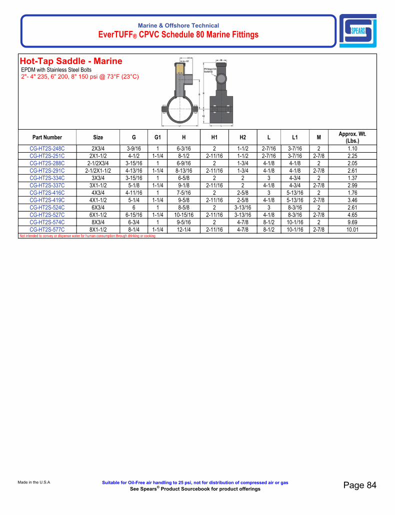
Marine & Offshore TechnicalEverTUFF® CPVC Schedule 80 Marine Fittings
Hot-Tap Saddle - MarineEPDM with Stainless Steel Bolts2"- 4" 235, 6" 200, 8" 150 psi @ 73°F (23°C)
Made in the U.S.A. Suitable for Oil-Free air handling to 25 psi, not for distribution of compressed air or gasSee Spears® Product Sourcebook for product offerings Page 84
Part Number Size G G1 H H1 H2 L L1 MApprox. Wt.
(Lbs.)CG-HT2S-248C 2X3/4 3-9/16 1 6-3/16 2 1-1/2 2-7/16 3-7/16 2 1.10CG-HT2S-251C 2X1-1/2 4-1/2 1-1/4 8-1/2 2-11/16 1-1/2 2-7/16 3-7/16 2-7/8 2.25CG-HT2S-288C 2-1/2X3/4 3-15/16 1 6-9/16 2 1-3/4 4-1/8 4-1/8 2 2.05CG-HT2S-291C 2-1/2X1-1/2 4-13/16 1-1/4 8-13/16 2-11/16 1-3/4 4-1/8 4-1/8 2-7/8 2.61CG-HT2S-334C 3X3/4 3-15/16 1 6-5/8 2 2 3 4-3/4 2 1.37CG-HT2S-337C 3X1-1/2 5-1/8 1-1/4 9-1/8 2-11/16 2 4-1/8 4-3/4 2-7/8 2.99CG-HT2S-416C 4X3/4 4-11/16 1 7-5/16 2 2-5/8 3 5-13/16 2 1.76CG-HT2S-419C 4X1-1/2 5-1/4 1-1/4 9-5/8 2-11/16 2-5/8 4-1/8 5-13/16 2-7/8 3.46CG-HT2S-524C 6X3/4 6 1 8-5/8 2 3-13/16 3 8-3/16 2 2.61CG-HT2S-527C 6X1-1/2 6-15/16 1-1/4 10-15/16 2-11/16 3-13/16 4-1/8 8-3/16 2-7/8 4.65CG-HT2S-574C 8X3/4 6-3/4 1 9-5/16 2 4-7/8 8-1/2 10-1/16 2 9.69CG-HT2S-577C 8X1-1/2 8-1/4 1-1/4 12-1/4 2-11/16 4-7/8 8-1/2 10-1/16 2-7/8 10.01
Not intended to convey or dispense water for human consumption through drinking or cooking

Marine & Offshore TechnicalEverTUFF® CPVC Schedule 80 Marine Fittings
Hot-Tap Saddle - MarineFKM with Stainless Steel Bolts2"- 4" 235, 6" 200, 8" 150 psi @ 73°F (23°C)
Page 85 Suitable for Oil-Free air handling to 25 psi, not for distribution of compressed air or gas Spears® Manufacturing CompanySee Spears® Product Sourcebook for product offerings
Part Number Size G G1 H H1 H2 L L1 MApprox. Wt.
(Lbs.)CG-HT3S-248C 2X3/4 3-9/16 1 6-3/16 2 1-1/2 2-7/16 3-7/16 2 1.11CG-HT3S-251C 2X-1-1/2 4-1/2 1-1/4 8-1/2 2-11/16 1-1/2 2-7/16 3-7/16 2-7/8 2.24CG-HT3S-288C 2-1/2X3/4 3-15/16 1 6-9/16 2 1-3/4 4-1/8 4-1/8 2 2.04CG-HT3S-291C 2-1/2X1-1/2 4-13/16 1-1/4 8-13/16 2-11/16 1-3/4 4-1/8 4-1/8 2-7/8 2.61CG-HT3S-334C 3X3/4 3-15/16 1 6-5/8 2 2 3 4-3/4 2 1.38CG-HT3S-337C 3X1-1/2 5-1/8 1-1/4 9-1/8 2-11/16 2 4-1/8 4-3/4 2-7/8 3.00CG-HT3S-416C 4X3/4 4-11/16 1 7-5/16 2 2-5/8 3 5-13/16 2 1.77CG-HT3S-419C 4X1-1/2 5-1/4 1-1/4 9-5/8 2-11/16 2-5/8 4-1/8 5-13/16 2-7/8 3.47CG-HT3S-524C 6X3/4 6 1 8-5/8 2 3-13/16 3 8-3/16 2 2.61CG-HT3S-527C 6X1-1/2 6-15/16 1-1/4 10-15/16 2-11/16 3-13/16 4-1/8 8-3/16 2-7/8 4.66CG-HT3S-574C 8X3/4 6-3/4 1 9-5/16 2 4-7/8 8-1/2 10-1/16 2 9.68CG-HT3S-577C 8X1-1/2 8-1/4 1-1/4 12-1/4 2-11/16 4-7/8 8-1/2 10-1/16 2-7/8 7.64
Not intended to convey or dispense water for human consumption through drinking or cooking
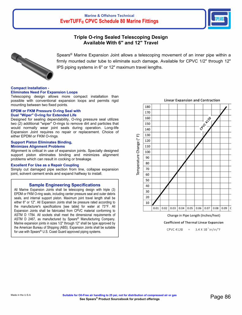
Marine & Offshore TechnicalEverTUFF® CPVC Schedule 80 Marine Fittings
Compact Installation -Eliminates Need For Expansion LoopsTelescoping design allows more compact installation than possible with conventional expansion loops and permits rigid mounting between two fixed points.EPDM or FKM Pressure O-ring Seal withDual "Wiper" O-ring for Extended LifeDesigned for sealing dependability, O-ring pressure seal utilizes two (2) additional "wiper" O-rings to remove dirt and particles that would normally wear joint seals during operation. Long-life Expansion Joint requires no repair or replacement. Choice of either EPDM or FKM O-rings.Support Piston Eliminates Binding, Minimizes Alignment ProblemsAlignment is critical in use of expansion joints. Specially designed support piston eliminates binding and minimizes alignment problems which can result in cocking or breakage.Excellent For Use as a Repair CouplingSimply cut damaged pipe section from line, collapse expansion joint, solvent cement ends and expand halfway to install.
Sample Engineering SpecificationsAll Marine Expansion Joints shall be telescoping design with triple (3) EPDM or FKM O-ring seals, including center pressure seal and outer debris seals, and internal support piston. Maximum joint travel length shall be either 6" or 12". All Expansion Joints shall be pressure rated according to the manufacturer's specifications [see table] for water at 73°F. All Expansion Joints shall be fabricated from CPVC material conforming to ASTM D 1784. All sockets shall meet the dimensional requirements of ASTM D 2467, as manufactured by Spears® Manufacturing Company. Marine expansion joints in sizes 1/2" through 12" shall be type approved by the American Bureau of Shipping (ABS). Expansion Joints shall be suitable for use with Spears® U.S. Coast Guard approved piping systems.
Made in the U.S.A. Suitable for Oil-Free air handling to 25 psi, not for distribution of compressed air or gasSee Spears® Product Sourcebook for product offerings Page 86
Triple O-ring Sealed Telescoping DesignAvailable With 6" and 12" Travel
Spears® Marine Expansion Joint allows a telescoping movement of an inner pipe within a firmly mounted outer tube to eliminate such damage. Available for CPVC 1/2" through 12" IPS piping systems in 6" or 12" maximum travel lengths.

Marine & Offshore TechnicalEverTUFF® CPVC Schedule 80 Marine Fittings
6" EXPANSION JOINT DIMENSION
Size M M1 L-CLOSED L-OPEN N-CLOSED N-OPENPressureRating
@ 73°F1/2" 1-3/16 1-3/4 10-9/16 16-9/16 8-13/16 14-13/16 2353/4" 1-7/16 2-1/8 12 18 10 16 2351" 1-5/8 2-3/8 12-1/2 18-1/2 10-1/4 16-1/4 235
1-1/4" 2-1/4 2-3/8 13-1/16 19-1/16 10-1/2 16-1/2 2351-1/2" 2-3/8 2-7/8 13-1/4 19-1/4 10-7/16 16-7/16 235
2" 2-7/8 3-1/2 14-7/16 20-7/16 11-7/16 17-7/16 2352-1/2" 4-3/16 4-1/2 16-1/4 22-1/4 12-3/4 18-3/4 150
3" 4-3/16 4-1/2 15-5/8 21-5/8 11-13/16 17-13/16 1504" 5-1/4 5-9/16 16-15/16 22-15/16 12-9/16 18-9/16 1506" 7-9/16 8-5/8 19-3/4 25-3/4 13-5/8 19-5/8 1508" 9-11/16 10-3/4 24-1/2 30-1/2 16-9/16 22-9/16 15010" 12-1/16 12-3/4 28-7/8 34-7/8 18-7/8 24-7/8 15012" 14-1/4 16 34 40 22 28 150
12" EXPANSION JOINT DIMENSIONS
Size M M1 L-CLOSED L-OPEN N-CLOSED N-OPENPressureRating
@ 73°F1/2" 1-3/16 1-3/4 16-9/16 28-9/16 14-13/16 26-13/16 2353/4" 1-7/16 2-1/8 18 30 16 28 2351" 1-5/8 2-3/8 18-1/2 30-1/2 16-1/4 28-1/4 235
1-1/4" 2-1/4 2-3/8 19-1/16 31-1/16 16-1/2 28-1/2 2351-1/2" 2-3/8 2-7/8 19-1/4 31-1/4 16-7/16 28-7/16 235
2" 2-7/8 3-1/2 20-7/16 32-7/16 17-7/16 29-7/16 2352-1/2" 4-3/16 4-1/2 22-1/4 34-1/4 18-3/4 30-3/4 150
3" 4-3/16 4-1/2 21-5/8 33-5/8 17-13/16 29-13/16 1504" 5-1/4 5-9/16 22-15/16 34-15/16 18-9/16 30-9/16 1506" 7-9/16 8-5/8 25-3/4 37-3/4 19-5/8 31-5/8 1508" 9-11/16 10-3/4 30-1/2 42-1/2 22-9/16 34-9/16 15010" 12-1/16 12-3/4 34-7/8 46-7/8 24-7/8 36-7/8 15012" 14-1/4 16 40 52 28 40 150
Page 87 Suitable for Oil-Free air handling to 25 psi, not for distribution of compressed air or gas Spears® Manufacturing CompanySee Spears® Product Sourcebook for product offerings
DETERMINING TRAVEL LENGTH NEEDEDGeneral Rule: For CPVC systems, allow 1/2" expansion for every 10°F change in temperature per 100 feet of pipe, (all diameters). For example, a 6" travel expansion joint will accommodate approximately 120°F temperature change in 100 ft. of CPVC pipe (12 x 1/2" = 6").
INSTALLATIONExpansion Joints consist of two telescoping tubes with internal O-ring seals. For proper operation, the outer tube should be firmly anchored to allow free movement of the inner tube or "piston". Support and thrust block the system to direct movement squarely into the Expansion Joint. Alignment is critical, axial guides should be installed to ensure straight movement into expansion joint. Provisions should be made to protect the cylinder shaft from scratches, damage and debris to prevent leaks. Expansion Joints can be installed at the travel range midpoint for most general installations and are shipped from the factory in this position. If desired, the extended position for installation may be additionally adjusted to specific system and installation parameters using the following calculation:

Marine & Offshore TechnicalEverTUFF® CPVC Schedule 80 Marine Fittings
Fabricated Expansion Joints - Marine6" Travel with EPDM O-rings1/2" - 2" 235 psi @ 73°F (23°C) 2-1/2" - 12" 150 psi @ 73°F (23°C)
Fabricated Expansion Joints - Marine12" Travel with EPDM O-rings1/2" - 2" 235 psi @ 73°F (23°C) 2-1/2" - 12" 150 psi @ 73°F (23°C)
Made in the U.S.A. Suitable for Oil-Free air handling to 25 psi, not for distribution of compressed air or gasSee Spears® Product Sourcebook for product offerings Page 88
Part Number Size L-Closed L-Open M M1 N-Closed N-Open TApprox. Wt.
(Lbs.)CG-826E-005X6C 1/2 10-9/16 16-9/16 1-3/16 1-3/4 8-13/16 14-13/16 6 .74CG-826E-007X6C 3/4 12 18 1-7/16 2-1/8 10 16 6 1.04CG-826E-010X6C 1 12-1/2 18-1/2 1-5/8 2-3/8 10-1/4 16-1/4 6 1.49CG-826E-012X6C 1 1/4 13-1/16 19-1/16 2-1/4 2-3/8 10-1/2 16-1/2 6 1.58CG-826E-015X6C 1-1/2 13-1/4 19-1/4 2-3/8 2-7/8 10-7/16 16-7/16 6 2.64CG-826E-020X6C 2 14-7/16 20-7/16 2-7/8 3-1/2 11-7/16 17-7/16 6 4.06CG-826E-025X6C 2-1/2 16-1/4 22-1/4 4-3/16 4-1/2 12-3/4 18-3/4 6 7.17CG-826E-030X6C 3 15-5/8 21-5/8 4-3/16 4-1/2 11-13/16 17-13/16 6 6.31CG-826E-040X6C 4 16-15/16 22-15/16 5-1/4 5-9/16 12-9/16 18-9/16 6 9.26CG-826E-060X6C 6 19-3/4 25-3/4 7-9/16 8-5/8 13-5/8 19-5/8 6 32.97CG-826E-080X6C 8 24-1/2 30-1/2 9-11/16 10-3/4 16-9/16 22-9/16 6 49.85CG-826E-100X6C 10 28-7/8 34-7/8 12-1/16 12-3/4 18-7/8 24-7/8 6 90.25CG-826E-120X6C 12 34 40 14-1/4 16 22 28 6 188.77
Part Number Size L-Closed L-Open M M1 N-Closed N-Open TApprox. Wt.
(Lbs.)CG-826E-005X12C 1/2 16-9/16 28-9/16 1-3/16 1-3/4 14-13/16 26-13/16 12 1.01CG-826E-007X12C 3/4 18 30 1-7/16 2-1/8 16 28 12 1.40CG-826E-010X12C 1 18-1/2 30-1/2 1-5/8 2-3/8 16-1/4 28-1/4 12 1.95CG-826E-012X12C 1-1/4 19-1/16 31-1/16 2-1/4 2-3/8 16-1/2 28-1/2 12 2.20CG-826E-015X12C 1-1/2 19-1/4 31-1/4 2-3/8 2-7/8 16-7/16 28-7/16 12 3.17CG-826E-020X12C 2 20-7/16 32-7/16 2-7/8 3-1/2 17-7/16 29-7/16 12 5.51CG-826E-025X12C 2-1/2 22-1/4 34-1/4 4-3/16 4-1/2 18-3/4 30-3/4 12 8.66CG-826E-030X12C 3 21-5/8 33-5/8 4-3/16 4-1/2 17-13/16 29-13/16 12 7.80CG-826E-040X12C 4 22-15/16 34-15/16 5-1/4 5-9/16 18-9/16 30-9/16 12 11.13CG-826E-060X12C 6 25-3/4 37-3/4 7-9/16 8-5/8 19-5/8 31-5/8 12 40.14CG-826E-080X12C 8 30-1/2 42-1/2 9-11/16 10-3/4 22-9/16 34-9/16 12 57.51CG-826E-100X12C 10 34-7/8 46-7/8 12-1/16 12-3/4 24-7/8 36-7/8 12 105.94CG-826E-120X12C 12 40 52 14-1/4 16 28 40 12 183.13

Marine & Offshore TechnicalEverTUFF® CPVC Schedule 80 Marine Fittings
Fabricated Expansion Joints - Marine6" Travel with FKM O-rings1/2" - 2" 235 psi @ 73°F (23°C) 2-1/2" - 12" 150 psi @ 73°F (23°C)
Fabricated Expansion Joints - Marine12" Travel with FKM O-rings1/2" - 2" 235 psi @ 73°F (23°C) 2-1/2" - 12" 150 psi @ 73°F (23°C)
Page 89 Suitable for Oil-Free air handling to 25 psi, not for distribution of compressed air or gas Spears® Manufacturing CompanySee Spears® Product Sourcebook for product offerings
Part Number Size L-Closed L-Open M M1 N-Closed N-Open TApprox. Wt.
(Lbs.)CG-826-005X6C 1/2 10-9/16 16-9/16 1-3/16 1-3/4 8-13/16 14-13/16 6 .77CG-826-007X6C 3/4 12 18 1-7/16 2- 1/8 10 16 6 1.07CG-826-010X6C 1 12-1/2 18-1/2 1-5/8 2-3/8 10-1/4 16-1/4 6 1.52CG-826-012X6C 1-1/4 13-1/16 19-1/16 2-1/4 2- 3/8 10-1/2 16-1/2 6 2.23CG-826-015X6C 1-1/2 13-1/4 19-1/4 2-3/8 2- 7/8 10-7/16 16-7/16 6 2.66CG-826-020X6C 2 14-7/16 20-7/16 2- 7/8 3- 1/2 11-7/16 17-7/16 6 4.11CG-826-025X6C 2-1/2 16-1/4 22-1/4 4- 3/16 4- 1/2 12-3/4 18-3/4 6 7.25CG-826-030X6C 3 15-5/8 21-5/8 4- 3/16 4- 1/2 11-13/16 17-13/16 6 6.37CG-826-040X6C 4 16-15/16 22-15/16 5-1/4 5- 9/16 12-9/16 18-9/16 6 9.32CG-826-060X6C 6 19-3/4 25-3/4 7-9/16 8- 5/8 13-5/8 19-5/8 6 33.06CG-826-080X6C 8 24-1/2 30-1/2 9-11/16 10- 3/4 16-9/16 22-9/16 6 49.97CG-826-100X6C 10 28-7/8 34-7/8 12-1/16 12- 3/4 18-7/8 24-7/8 6 90.45CG-826-120X6C 12 34 40 14-1/4 16 22 28 6 188.48
Part Number Size L-Closed L-Open M M1 N-Closed N-Open TApprox. Wt.
(Lbs.)CG-826-005X12C 1/2 16-9/16 28-9/16 1-3/16 1-3/4 14-13/16 26-13/16 12 1.04CG-826-007X12C 3/4 18 30 1-7/16 2- 1/8 16 28 12 1.42CG-826-010X12C 1 18-1/2 30-1/2 1-5/8 2-3/8 16-1/4 28-1/4 12 1.98CG-826-012X12C 1-1/4 19-1/16 31-1/16 2-1/4 2- 3/8 16-1/2 28-1/2 12 2.23CG-826-015X12C 1-1/2 19-1/4 31-1/4 2-3/8 2- 7/8 16-7/16 28-7/16 12 3.74CG-826-020X12C 2 20-7/16 32-7/16 2- 7/8 3- 1/2 17-7/16 29-7/16 12 5.56CG-826-025X12C 2-1/2 22-1/4 34-1/4 4- 3/16 4- 1/2 18-3/4 30-3/4 12 9.15CG-826-030X12C 3 21-5/8 33-5/8 4- 3/16 4- 1/2 17-13/16 29-13/16 12 8.27CG-826-040X12C 4 22-15/16 34-15/16 5-1/4 5- 9/16 18-9/16 30-9/16 12 11.88CG-826-060X12C 6 25- 3/4 37-3/4 7-9/16 8- 5/8 19-5/8 31-5/8 12 42.17CG-826-080X12C 8 30-1/2 42-1/2 9-11/16 10- 3/4 22-9/16 34-9/16 12 57.61CG-826-100X12C 10 34-7/8 46-7/8 12-1/16 12- 3/4 24-7/8 36-7/8 12 106.13CG-826-120X12C 12 40 52 14-1/4 16 28 40 12 212.61

Marine & Offshore TechnicalEverTUFF® CPVC Schedule 80 Marine Fittings
GripLoc™ Coupling - MarineWARNING: DO NOT INSERT FINGERSEPDM GasketPressure Rated to 235 psi @ 73°FDo Not Use Solvent Cement.
GripLoc™ Cap - MarineWARNING: DO NOT INSERT FINGERSEPDM GasketPressure Rated to 235 psi @ 73°FDo Not Use Solvent Cement.
Made in the U.S.A. Suitable for Oil-Free air handling to 25 psi, not for distribution of compressed air or gasSee Spears® Product Sourcebook for product offerings Page 90
GripLoc™ Marine Coupling
GripLoc™ Marine Coupling Specially designed stainless steel Gripper Ring to firmly grip pipe and prevent potential pull-out. Compressed Gland Ring ensures positive O-ring seal against pipe.
Part Number Size L L1 M NApprox. Wt.
(Lbs.)CG-GL429-005C 1/2 3-13/16 1-27/32 1-5/8 1/8 .20CG-GL429-007C 3/4 4 1-15/16 1-29/32 1/8 .27CG-GL429-010C 1 4-3/16 2-1/32 2-1/4 1/8 .38CG-GL429-012C 1-1/4 4-5/16 2-3/32 2-23/32 1/8 .51CG-GL429-015C 1-1/2 4-5/16 2-3/32 3 1/8 .60CG-GL429-020C 2 4-1/2 2-3/16 3-5/8 1/8 .89
Gripper is 410 Stainless Steel
Part Number Size M WApprox. Wt.
(Lbs.)CG-GL447-005C 1/2 1-5/8 1-5/8 .11CG-GL447-007C 3/4 1-15/16 1-3/4 .14CG-GL447-010C 1 2-5/16 2 .20CG-GL447-012C 1-1/4 2-23/32 2-1/8 .29CG-GL447-015C 1-1/2 3 2-3/16 .35CG-GL447-020C 2 3-5/8 2-7/16 .54
Gripper is 410 Stainless Steel

Marine & Offshore TechnicalEverTUFF® CPVC Schedule 40 & 80 Marine Pressure System
Page 91 Suitable for Oil-Free air handling to 25 psi, not for distribution of compressed air or gas Spears® Manufacturing CompanySee Spears® Product Sourcebook for product offerings
GripLoc™ Marine Coupling Installation

Marine & Offshore TechnicalEverTUFF® CPVC Schedule 40 & 80 Marine Pressure System
Features This multi-featured, space saving quarter-turn shutoff valve is designed to meet the demands of today's marine and chemical processing applications. CPVC marine valves are available in IPS sizes 1/2" through 6", regular thread thru 2" and 8" venturied valve socket ends.
Sample Engineering SpecificationAll thermoplastic 2000 marine ball valves shall be True Union 2000 manufactured to ASTM F 1970 and constructed from CPVC Type IV, ASTM D 1784 Cell Classification 23447 per ASTM D 1784. All O-rings shall be EPDM or FKM. All valves shall have Safe-T-Shear® stem with double O-ring stem seals. All valve handles shall be polypropylene with built-in lockout mechanism. All valve union nuts shall have Buttress threads. All seal carriers shall be Safe-T-Blocked®. All valve components shall be replaceable. All valves with EPDM elastomers shall be certified by NSF International for use in potable water service. All 1/2" through 4" valves shall be pressure rated to 235 psi, with a Limited Lifetime Warranty as manufactured by Spears® Manufacturing Company. CPVC marine ball valves in sizes 1/2" thru 4" shall be type approved by the American Bureau of Shipping (ABS). CPVC marine ball values in sizes 1/2" thur 8" are suitable for use with Spears® U.S. Coast Guard Approved piping systems.
Quick-View Valve Selection Chart
Valve SizeO-ring
MaterialCPVC Part Number Pressure
RatingSocket Threaded
1/2EPDM CG-1829-005C included
235 psiNon-Shock Water
@ 73°F
(Flanged 150 psi
Non-Shock) Water
@ 73°F
FKM CG-1839-005C included
3/4EPDM CG-1829-007C included
FKM CG-1839-007C included
1EPDM CG-1829-010C included
FKM CG-1839-010C included
1-1/4EPDM CG-1829-012C included
FKM CG-1839-012C included
1-1/2EPDM CG-1829-015C included
FKM CG-1839-015C included
2EPDM CG-1829-020C included
FKM CG-1839-020C included
2-1/2EPDM CG-1822-025C N/A
FKM CG-1832-025C N/A
3EPDM CG-1822-030C N/A
FKM CG-1832-030C N/A
4EPDM CG-1822-040C N/A
FKM CG-1832-040C N/A
6EPDM CG-1822-060C N/A 150 psi
Non-ShockWater
@ 73°F
FKM CG-1832-060C N/A
81 EPDM CG-1822-080C N/A;
FKM CG-1832-080C N/A
1) Venturied Valves are 6" ball valves fitted with 6x8 end connector adapters.
• Chemical & Corrosion Resistant CPVC Construction• Interchangeable with all True Union 2000 Valves
Mates with Union 2000 Pipe Unions• High Impact Polypropylene Handle• Built-in Handle Lockout• Schedule 80 Full-Port Design• Strong, Buttress Thread Union Nuts• Spears® Double O-ring Safe-T-Shear®
Stem Design• EPDM or FKM O-rings• Spears® Safe-T-Blocked® Seal Carrier• Self Adjusting PTFE Floating Seat Design• Fully Serviceable, Replaceable Components• Sizes 1/2"-4" Pressure Rated to 235 psi @ 73°F.
Sizes 6" and 8" Venturied and all Flanged to 150 psi @ 73°F.
• EPDM Valves NSF® Certified for Potable Water use• Assembled with Silicone-Free, Water Soluble
Lubricants• Manufactured to ASTM F 1970
Optional Accessories
• Retro-Fit End Connector Sets for Valve Replacement
• Split-Nut Repair Kits for Union Nut Replacement• Supplemental End Connectors• Round Safety Handles• Handle Lockout Ring• Stem Extension Kits• Square Operator Nuts• Multi Mount Valve/Actuation Mounting Kits• Mini-Mount Actuation Mounting Kits
Made in the U.S.A. Suitable for Oil-Free air handling to 25 psi, not for distribution of compressed air or gasSee Spears® Product Sourcebook for product offerings Page 92
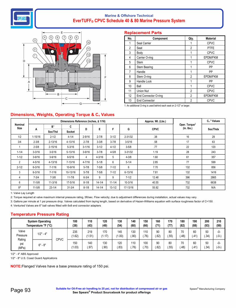
Marine & Offshore TechnicalEverTUFF® CPVC Schedule 40 & 80 Marine Pressure System
Replacement PartsNo. Component Qty. Material
1 Seal Carrier 1 CPVC
2 Seat 2 PTFE
3 Body 1 CPVC
4 Carrier O-ring 1 EPDM/FKM
5 Stem 1 CPVC
6 Stem Bearing 1 PP
7 Handle 1 PP
8 Stem O-ring 2 EPDM/FKM
9 Handle Lock 1 PP
10 Ball 1 CPVC
11 Union Nut 2 CPVC
12 End Connector O-ring 2 EPDM/FKM
13 End Connector 2 CPVC
1: An additional O-ring is used behind each seat on 2-1/2" or larger.
Page 93 Suitable for Oil-Free air handling to 25 psi, not for distribution of compressed air or gas Spears® Manufacturing CompanySee Spears® Product Sourcebook for product offerings
Dimensions, Weights, Operating Torque & Cv Values
Nominal Size
Dimensions Reference (inches, ± 1/16) Approx. Wt. (Lbs.)Oper. Torque2
(in. lbs.)
Cv3 Values
AB1 C
D E F G CPVC Soc/ThdxSoc/Thd Socket
1/2 1-15/16 2-1/2 4-1/4 2-9/16 2-7/8 3-1/2 2-31/32 .38 16 29
3/4 2-3/8 2-13/16 4-13/16 2-7/8 3-3/8 3-7/8 3-5/16 .58 17 63
1 2-5/8 2-15/16 5-3/16 3-1/16 3-1/2 4-1/2 3-5/8 .77 22 120
1-1/4 3-3/16 3-5/16 5-13/16 3-9/16 3-7/8 4-5/8 3-31/32 1.19 28 243
1-1/2 3-9/16 3-9/16 6-5/16 4 4-3/16 5 4-3/8 1.60 61 357
2 4-5/16 4-13/16 7-13/16 4-7/16 5-1/8 6 5-1/4 2.85 77 599
2-1/2 6-3/16 7-1/16 10-9/16 5-7/8 7-5/8 7-1/2 6 7.70 132 856
3 6-3/16 7-1/16 10-13/16 5-7/8 7-5/8 7-1/2 6-13/16 7.81 132 1416
4 7-3/4 7-3/8 11-7/8 6-3/4 9 9 7-1/2 12.48 396 2865
6 11-5/8 11-3/16 17-5/16 8-1/8 14-1/4 11-1/4 10-3/16 40.55 732 6638
84 11-5/8 23-1/4 31-3/4 8-1/8 14-1/4 13-1/2 17-13/16 55.92 732 N/A
1: Valve Lay Length2: Torque required at valve maximum internal pressure rating, 5ft/sec. Flow velocity; due to adjustment differences during installation, actual values may vary.3: Gallons per minute at 1 psi pressure drop. Valves calculated from laying length, based on derivative of Hazen-Williams equation with surface roughness factor of C=150.4: Venturied Valves are 6" ball valves fitted with 6x8 end connector adapters.
Temperature Pressure RatingSystem Operating
Temperature °F (°C)100(38)
110(43)
120(49)
130(54)
140(60)
150(66)
160(71)
170(77)
180(82)
190(88)
200(93)
210(99)
ValvePressure Rating
psi(MPa)
1/2" - 4"
CPVC
235(1.62)
219(1.51)
170(1.17)
145(1.00)
130(.90)
110(.76)
90(.62)
80(.55)
70(.48)
60(.41)
50(.34)
-0-(-0-)
6" - 8"150
(1.03)140(.97)
130(.90)
120(.83)
110(.76)
100(.70)
90(.62)
80(.55)
70(.48)
60(.41)
50(.34)
-0-(-0-)
1/2" - 4" ABS Approved1/2" - 8" U.S. Coast Guard Applications
NOTE:Flanged Valves have a base pressure rating of 150 psi.

Marine & Offshore TechnicalEverTUFF® CPVC Schedule 40 & 80 Marine Pressure System
True Union 2000 Industrial Ball Valves - EPDM - MarineSocket
True Union 2000 Industrial Ball Valves - FKM - MarineSocket
Made in the U.S.A. Suitable for Oil-Free air handling to 25 psi, not for distribution of compressed air or gasSee Spears® Product Sourcebook for product offerings Page 94
Part Number Size A B C D E Cv ValuesApprox. Wt.
(Lbs.)CG-1829-005C 1/2 1-15/16 2-1/2 4-1/4 2- 9/16 2-7/8 29 .48CG-1829-007C 3/4 2-3/8 2-13/16 4-13/16 2- 7/8 3-3/8 63 .72CG-1829-010C 1 2-5/8 2-15/16 5-3/16 3-1/16 3-1/2 120 1.00CG-1829-012C 1-1/4 3-3/16 3-5/16 5-13/16 3-9/16 3-7/8 243 1.48CG-1829-015C 1-1/2 3-9/16 3-9/16 6-5/16 4 4- 3/16 357 1.97CG-1829-020C 2 4-5/16 4-13/16 7-13/16 4-7/16 5- 1/8 599 3.38CG-1822-025C 2-1/2 6- 3/16 7-1/16 10- 9/16 5- 7/8 7- 5/8 856 8.51CG-1822-030C 3 6- 3/16 7-1/16 10-13/16 5- 7/8 7- 5/8 1416 8.34CG-1822-040C 4 7- 3/4 7-3/8 11-7/8 6- 3/4 9 2865 14.44CG-1822-060C 6 11- 5/8 11-3/16 17-5/16 8- 1/8 14-1/4 6638 41.70CG-1822-080C 8 11-5/8 23-1/4 31-3/4 8-1/8 14-1/4 6638 53.82
Part Number Size A B C D E Cv ValuesApprox. Wt.
(Lbs.)CG-1839-005C 1/2 1-15/16 2-1/2 4-1/4 2- 9/16 2-7/8 29 .48CG-1839-007C 3/4 2-3/8 2-13/16 4-13/16 2- 7/8 3-3/8 63 .72CG-1839-010C 1 2-5/8 2-15/16 5-3/16 3-1/16 3-1/2 120 1.00CG-1839-012C 1-1/4 3-3/16 3-5/16 5-13/16 3-9/16 3-7/8 243 1.48CG-1839-015C 1-1/2 3-9/16 3-9/16 6-5/16 4 4- 3/16 357 1.98CG-1839-020C 2 4-5/16 4-13/16 7-13/16 4-7/16 5- 1/8 599 3.40CG-1832-025C 2-1/2 6- 3/16 7-1/16 10- 9/16 5- 7/8 7- 5/8 856 8.56CG-1832-030C 3 6- 3/16 7-1/16 10-13/16 5- 7/8 7- 5/8 1416 8.39CG-1832-040C 4 7- 3/4 7-3/8 11-7/8 6- 3/4 9 2865 14.50CG-1832-060C 6 11- 5/8 11-3/16 17-5/16 8- 1/8 14-1/4 6638 41.85CG-1832-080C 8 11-5/8 23-1/4 31-3/4 8-1/8 14-1/4 6638 53.96

Marine & Offshore TechnicalEverTUFF® CPVC Schedule 40 & 80 Marine Pressure System
Sample Engineering SpecificationAll thermoplastic Standard marine ball valves shall be True Union 2000 series manufactured to ASTM F 1970 and constructed from CPVC Type IV, ASTM D1784 Cell Classification 23447 per ASTM D1784. All O- rings shall be EPDM or FKM. All valves shall have Safe-T-Shear® stem with double O-ring stem seals. All valve handles shall be polypropylene. All valve union nuts shall have Buttress threads. All seal carriers shall be Safe-T- Blocked®. All valve components shall be replaceable. All valves with EPDM elastomers shall be certified by NSF International for use in potable water service. Valves 1/2" through 2" shall be pressure rated to 235 psi, 2-1/2" through 4" and all flanged valves shall be pressure rated to 150psi @ 73°F. with a Limited Lifetime Warranty as manufactured by Spears® Manufacturing Company. All CPVC Standard Marine Ball Valves 1/2" through 4" shall be type approved by the American Bureau of Shipping (ABS) and suitable for use with Spears® U.S. Coast Guard Approved piping systems.
FeaturesEconomical, low profile quarter-turn shutoff valve is excellent for marine and many O.E.M applications. CPVC valves are available in IPS sizes 1/2" through 4".
• New Actuator-Ready Body — Accepts Spears®
Improved Mini-Mount Actuator Mounting Kits• New Double O-ring Stem Seal• Schedule 80 Full-Port Design• Spears® Safe-T-Shear Stem• PTFE/HDPE Self Adjusting Floating Seats• EPDM or FKM O-ring Seals• Sizes 1/2" - 2" Pressure Rated to 235 psi @ 73°F.
Sizes 2-1/2" - 4" and all Flanged to 150 psi @ 73°F.• EPDM valves NSF® Certified for Use with Potable
Water• Manufactured to ASTM F 1970
Optional Accessories• Round Safety Handles• Stem Extension Kits• Square Operator Nuts• Multi Mount Valve/Actuation Mounting Kits• Mini-Mount Actuation Mounting Kits
Quick-View Valve Selection ChartValveSize
O-ringMaterial
CPVC Part Number PressureRatingSocket Threaded
1/2EPDM CG-3629-005C Included
235 psiNon-Shock
Water@73°F
(Flanged150 psi
Non-Shock)Water @73°F
FKM CG-3639-005C Included
3/4EPDM CG-3629-007C Included
FKM CG-3639-007C Included
1EPDM CG-3629-010C Included
FKM CG-3639-010C Included
1-1/4EPDM CG-3629-012C Included
FKM CG-3639-012C Included
1-1/2EPDM CG-3629-015C Included
FKM CG-3639-015C Included
2EPDM CG-3629-020C Included
FKM CG-3639-020C Included
2-1/2EPDM CG-3622-025C N/A
FKM CG-3632-025C N/A
3EPDM CG-3622-030C N/A
FKM CG-3632-030C N/A
4EPDM CG-3622-040C N/A
FKM CG-3632-040C N/A
Page 95 Suitable for Oil-Free air handling to 25 psi, not for distribution of compressed air or gas Spears® Manufacturing CompanySee Spears® Product Sourcebook for product offerings

Marine & Offshore TechnicalEverTUFF® CPVC Schedule 40 & 80 Marine Pressure System
Replacement PartsNo. Component Qty. Material
1 Seal Carrier 1 CPVC
2 Body 1 CPVC
3 Carrier O-ring 1 EPDM/FKM
4 Stem Bearing 1,2 1 PP
5 Stem 1 CPVC
6 Handle 1 PP
7 Stem O-ring 1 EPDM/FKM
8 Ball 1 CPVC
9 Seat 2 PTFE/HDPE
10 Union Nut 2 CPVC
11 End Connector O-ring 2 EPDM/FKM
12 End Connector 2 CPVC
1: O-Ring up to 2"2: PTFE Thrust Bearing: 2-1/2", 3" & 4"3: An additional O-ring is used behind each seat on 2-1/2" or larger.
Made in the U.S.A. Suitable for Oil-Free air handling to 25 psi, not for distribution of compressed air or gasSee Spears® Product Sourcebook for product offerings Page 96
Dimensions, Weights, Operating Torque & Cv Values
Nominal Size
Dimensions Reference (inches, ± 1/16) Approx. Wt. (Lbs.)Oper. Torque2
(in. lbs.)
Cv3 Values
AB1 C
D E F G CPVC Soc/ThdxSoc/Thd Socket
1/2 1-15/16 2-1/2 4-1/4 1-5/8 2-1/2 3-1/2 2-31/32 .35 12 29
3/4 2-3/8 2-13/16 4-13/16 2 3 3-7/8 3-5/16 .54 20 63
1 2-11/16 2-15/16 5-3/16 2-5/16 3-5/16 4-1/4 3-5/8 .75 25 120
1-1/4 3-3/16 3-1/4 5-3/4 2-13/16 3-9/16 4-5/8 3-31/32 1.17 35 243
1-1/2 3-9/16 3-9/16 6-5/16 3-1/16 3-7/8 5 4-3/8 1.53 45 357
2 4-5/16 4-13/16 7-13/16 3-3/4 4-15/16 6 5-1/4 2.75 94 599
2-1/2 6-3/16 7-1/8 10-5/8 5-1/2 7-5/8 7 6-9/16 7.70 120 856
3 6-3/16 7-1/16 10-13/16 5-1/2 7-5/8 7-1/2 6-7/8 7.81 120 1416
4 7-3/4 7-5/16 11-13/16 6-1/8 9-1/16 9-1/16 7-1/2 12.48 336 2865
1: Valve Lay Length2: Torque required at valve maximum internal pressure rating, 5ft/sec. flow velocity; due to adjustment differences during installation, actual values may vary.3: Gallons per minute at 1 psi pressure drop. Valves calculated from laying length, based on derivative of Hazen-Williams equation with surface roughness factor of C=150.
Temperature Pressure RatingSystem Operating
Temperature °F (°C)100(38)
110(43)
120(49)
130(54)
140(60)
150(66)
160(71)
170(77)
180(82)
190(88)
200(93)
210(99)
ValvePressure Rating
psi(MPa)
1/2" - 4" CPVC
235(1.62)
219(1.51)
170(1.17)
145(1.00)
130(.90)
110(.76)
90(.62)
80(.55)
70(.48)
60(.41)
50(.34)
-0-(-0-)
150(1.03)
140(.97)
130(.90)
120(.83)
110(.76)
100(.70)
90(.62)
80(.55)
70(.48)
60(.41)
50(.34)
-0-(-0-)
1/2" - 4" ABS Approved1/2" - 8" U.S. Coast Guard Applications
NOTE: Flanged Valves have a base pressure rating of 150 psi.

Marine & Offshore TechnicalEverTUFF® CPVC Schedule 40 & 80 Marine Pressure System
True Union 2000 Standard Ball Valves - EPDM - MarineSocket
True Union 2000 Standard Ball Valves - FKM - MarineSocket
Page 97 Suitable for Oil-Free air handling to 25 psi, not for distribution of compressed air or gas Spears® Manufacturing CompanySee Spears® Product Sourcebook for product offerings
Part Number Size A B C D E Cv ValuesApprox. Wt.
(Lbs.)CG-3629-005C 1/2 1-15/16 2-1/2 4-1/4 1- 5/8 2- 1/2 29 .45CG-3629-007C 3/4 2-3/8 2-13/16 4-13/16 2 3 63 .68CG-3629-010C 1 2-11/16 2-15/16 5-3/16 2- 5/16 3-5/16 120 .96CG-3629-012C 1-1/4 3-3/16 3- 1/4 5- 3/4 2-13/16 3- 9/16 243 1.43CG-3629-015C 1-1/2 3-9/16 3-9/16 6-5/16 3- 1/16 3- 7/8 357 1.90CG-3629-020C 2 4- 5/16 4-13/16 7-13/16 3-3/4 4-15/16 599 3.28CG-3622-025C 2-1/2 6- 3/16 7-1/8 10-5/8 5-1/2 7- 5/8 856 8.40CG-3622-030C 3 6- 3/16 7-1/6 10-13/16 5-1/2 7- 5/8 1416 8.23CG-3622-040C 4 7-3/4 7- 5/16 11-13/16 6-1/8 9-1/16 2865 14.15
Part Number Size A B C D E Cv ValuesApprox. Wt.
(Lbs.)CG-3639-005C 1/2 1-15/16 2-1/2 4-1/4 1- 5/8 2- 1/2 29 .45CG-3639-007C 3/4 2-3/8 2-13/16 4-13/16 2 3 63 .68CG-3639-010C 1 2-11/16 2-15/16 5-3/16 2- 5/16 3-5/16 120 .96CG-3639-012C 1-1/4 3-3/16 3- 1/4 5- 3/4 2-13/16 3- 9/16 243 1.44CG-3639-015C 1-1/2 3-9/16 3-9/16 6-5/16 3- 1/16 3- 7/8 357 1.91CG-3639-020C 2 4- 5/16 4-13/16 7-13/16 3-3/4 4-15/16 599 3.30CG-3632-025C 2-1/2 6- 3/16 7-1/8 10-5/8 5-1/2 7- 5/8 856 8.44CG-3632-030C 3 6- 3/16 7-1/16 10-13/16 5-1/2 7- 5/8 1416 8.27CG-3632-040C 4 7-3/4 7- 5/16 11-13/16 6-1/8 9-1/16 2865 14.21
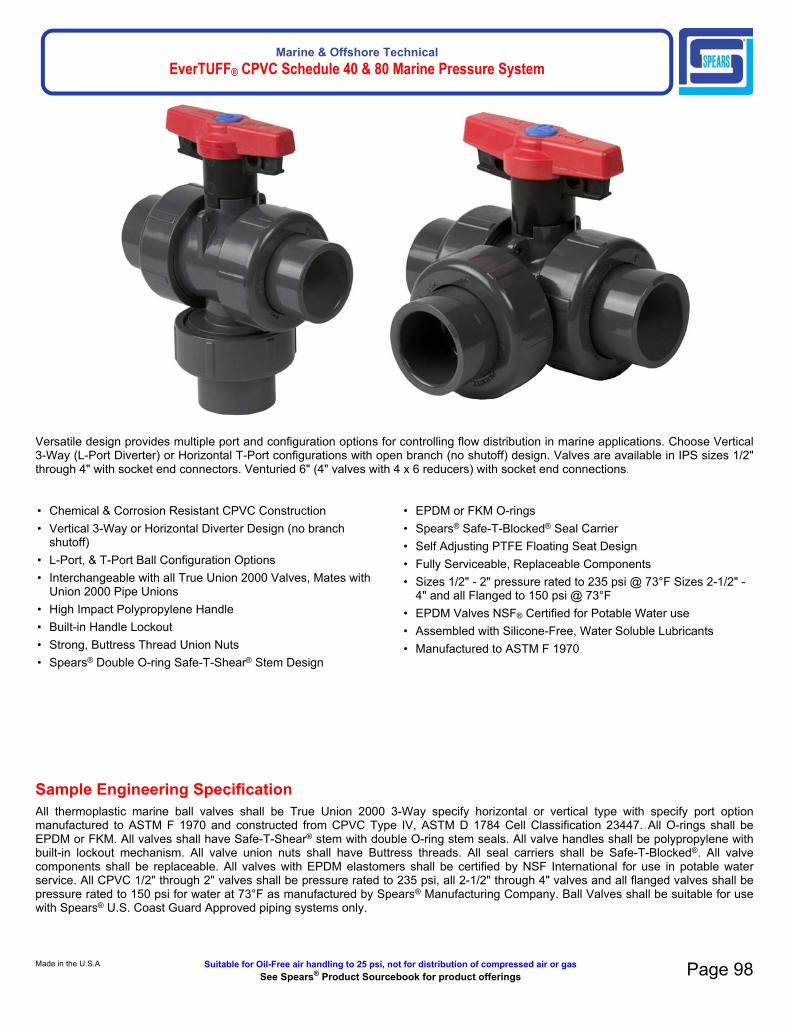
Marine & Offshore TechnicalEverTUFF® CPVC Schedule 40 & 80 Marine Pressure System
• Chemical & Corrosion Resistant CPVC Construction• Vertical 3-Way or Horizontal Diverter Design (no branch
shutoff)• L-Port, & T-Port Ball Configuration Options• Interchangeable with all True Union 2000 Valves, Mates with
Union 2000 Pipe Unions• High Impact Polypropylene Handle• Built-in Handle Lockout• Strong, Buttress Thread Union Nuts• Spears® Double O-ring Safe-T-Shear® Stem Design
• EPDM or FKM O-rings• Spears® Safe-T-Blocked® Seal Carrier• Self Adjusting PTFE Floating Seat Design• Fully Serviceable, Replaceable Components• Sizes 1/2" - 2" pressure rated to 235 psi @ 73°F Sizes 2-1/2" -
4" and all Flanged to 150 psi @ 73°F• EPDM Valves NSF® Certified for Potable Water use• Assembled with Silicone-Free, Water Soluble Lubricants• Manufactured to ASTM F 1970
Sample Engineering SpecificationAll thermoplastic marine ball valves shall be True Union 2000 3-Way specify horizontal or vertical type with specify port option manufactured to ASTM F 1970 and constructed from CPVC Type IV, ASTM D 1784 Cell Classification 23447. All O-rings shall be EPDM or FKM. All valves shall have Safe-T-Shear® stem with double O-ring stem seals. All valve handles shall be polypropylene with built-in lockout mechanism. All valve union nuts shall have Buttress threads. All seal carriers shall be Safe-T-Blocked®. All valve components shall be replaceable. All valves with EPDM elastomers shall be certified by NSF International for use in potable water service. All CPVC 1/2" through 2" valves shall be pressure rated to 235 psi, all 2-1/2" through 4" valves and all flanged valves shall be pressure rated to 150 psi for water at 73°F as manufactured by Spears® Manufacturing Company. Ball Valves shall be suitable for use with Spears® U.S. Coast Guard Approved piping systems only.
Made in the U.S.A. Suitable for Oil-Free air handling to 25 psi, not for distribution of compressed air or gasSee Spears® Product Sourcebook for product offerings Page 98
Versatile design provides multiple port and configuration options for controlling flow distribution in marine applications. Choose Vertical 3-Way (L-Port Diverter) or Horizontal T-Port configurations with open branch (no shutoff) design. Valves are available in IPS sizes 1/2" through 4" with socket end connectors. Venturied 6" (4" valves with 4 x 6 reducers) with socket end connections.

Marine & Offshore TechnicalEverTUFF® CPVC Schedule 40 & 80 Marine Pressure System
Quick-View Valve Selection Chart3-Way Vertical Ball Valve
Valve
SizeO-ring Material
PVC Part Number Pressure
RatingSocket
1/2EPDM CG-4722L1-005C
235 psi Non-Shock
Water @ 73°F
FKM CG-4732L1-005C
3/4EPDM CG-4722L1-007C
FKM CG-4732L1-007C
1EPDM CG-4722L1-010C
FKM CG-4732L1-010C
1-1/4EPDM CG-4722L1-012C
FKM CG-4732L1-012C
1-1/2EPDM CG-4722L1-015C
FKM CG-4732L1-015C
2EPDM CG-4722L1-020C
FKM CG-4732L1-020C
2-1/2EPDM CG-4722L1-025C
150 psi Non-Shock
Water @ 73°F
FKM CG-4732L1-025C
3EPDM CG-4722L1-030C
FKM CG-4732L1-030C
4EPDM CG-4722L1-040C
FKM CG-4732L1-040C
3-Way Port OptionsDiverter Valves have no shut-off on branch.
Optional Accessories*
• Retro-Fit End Connector Sets for Valve Replacement• Split-Nut Repair Kits for Union Nut Replacement• Supplemental End Connectors• Stem Extension Kits• Square Operator Nuts• Multi Mount Valve/Actuation Mounting Kits
* See "BALL VALVE ACCESSORIES" section for details of individual products.
Quick-View Valve Selection Chart3-Way Horizontal Diverter Valve (no branch shutoff)
Valve
SizeO-ring Material
CPVC Part Number Pressure
RatingSocket
1/2EPDM CG-5022L1-005C
235 psi Non-Shock
Water @ 73°F
FKM CG-5032L1-005C
3/4EPDM CG-5022L1-007C
FKM CG-5032L1-007C
1EPDM CG-5022L1-010C
FKM CG-5032L1-010C
1-1/4EPDM CG-5022L1-012C
FKM CG-5032L1-012C
1-1/2EPDM CG-5022L1-015C
FKM CG-5032L1-015C
2EPDM CG-5022L1-020C
FKM CG-5032L1-020C
2-1/2EPDM CG-5022L1-025C
150 psi Non-Shock
Water @ 73°F
FKM CG-5032L1-025C
3EPDM CG-5022L1-030C
FKM CG-5032L1-030C
4EPDM CG-5022L1-040C
FKM CG-5032L1-040C
Page 99 Suitable for Oil-Free air handling to 25 psi, not for distribution of compressed air or gas Spears® Manufacturing CompanySee Spears® Product Sourcebook for product offerings

Marine & Offshore TechnicalEverTUFF® CPVC Schedule 40 & 80 Marine Pressure System
Replacement PartsNo. Component Qty. Material1 End Connector 3 CPVC2 End Connector O-ring 3 EPDM/FKM3 Union Nut 3 CPVC4 Handle Lock 1 PP5 Handle 1 PP6 Stem 1 CPVC7 Screw 1 Stainless Steel8 Handle Cover 1 PP9 Stem O-ring 2 EPDM/FKM10 Stem Bearing* 1 PTFE11 Body 1 CPVC12 Ball 1 CPVC13 End Connector Collar 3 Stainless Steel14 Seat 2 PTFE15 Carrier O-ring 1 EPDM/FKM16 Seal Carrier 1 CPVC
Note: Applies to both Vertical and Horizontal configurations.* For sizes 2-1/2, 3 & 4 only.
Made in the U.S.A. Suitable for Oil-Free air handling to 25 psi, not for distribution of compressed air or gasSee Spears® Product Sourcebook for product offerings Page 100
NOTE: Diverter style valve has no shutoff on branch.
Vertical 3-Way Ball Valves — Dimensions & Operating TorqueDimensions Reference (Inches,± 1/16)
Oper. Torque2
(in. lbs.)
Approx.Wt. (lbs.)
CPVCNominal
SizeA
B1 CD E F G
Socket Socket1/2 1-15/16 2-1/2 4-1/4 2-17/32 2-7/8 2-11/16 1-13/16 12 0.543/4 2-3/8 2-3/4 4-3/4 2-7/8 3-3/8 3-1/16 2-1/16 12 0.831 2-11/16 2-15/16 5-3/16 3-1/16 3-1/2 3-5/16 2-3/16 20 1.12
1-1/4 3-3/16 3-5/16 5-13/16 3-5/8 3-7/8 3-3/4 2-1/2 25 1.721-1/2 3-5/8 3-5/8 6-3/8 4 4-3/16 4-5/16 2-15/16 40 2.30
2 4-5/16 4-7/8 7-7/8 4-7/16 5-1/16 5 3-1/2 67 4.022-1/2 6-3/16 7-1/8 10-5/8 5-7/8 7-5/8 6-5/8 4-7/8 120 9.92
3 6-3/16 7 10-3/4 5-7/8 7-5/8 6-3/4 4-7/8 120 10.114 7-3/4 7-7/16 11-15/16 6-11/16 9 8-3/8 5-15/16 336 21.72
1: Valve Lay Length2: Torque required at valve maximum internal pressure rating, 5ft/sec. Flow velocity; due to adjustment differences during installation, actual values may vary.

Marine & Offshore TechnicalEverTUFF® CPVC Schedule 40 & 80 Marine Pressure System
Page 101 Suitable for Oil-Free air handling to 25 psi, not for distribution of compressed air or gas Spears® Manufacturing CompanySee Spears® Product Sourcebook for product offerings
NOTE: Diverter style valve has no shutoff on branch
Horizontal Diverter 3-Way Ball Valves Dimensions & Operating TorqueDimensions Reference (Inches,± 1/16)
Oper. Torque2
(in. lbs.)
Approx.Wt. (lbs.)
CPVCNominal
SizeA
B1 CD E F G
Socket Socket
1/2 1-15/16 2-1/2 4-1/4 2-17/32 2-7/8 2-3/4 1-7/8 12 0.55
3/4 2-3/8 2-3/4 4-3/4 2-7/8 3-3/8 3-1/8 2-1/8 12 0.84
1 2-11/16 2-15/16 5-3/16 3-1/16 3-1/2 3-5/16 2-3/16 20 1.11
1-1/4 3-3/16 3-5/16 5-13/16 3-5/8 3-7/8 3-13/16 2-9/16 25 1.72
1-1/2 3-5/8 3-5/8 6-3/8 4 4-3/16 4-5/16 2-15/16 40 2.24
2 4-5/16 4-7/8 7-7/8 4-7/16 5-1/16 5-1/16 3-9/16 67 4.04
2-1/2 6-3/16 7-1/8 10-5/8 5-7/8 7-5/8 6-5/8 4-7/8 120 9.84
3 6-3/16 7 10-3/4 5-7/8 7-5/8 6-3/4 4-7/8 120 10.03
4 7-3/4 7-7/16 11-15/16 6-11/16 9 8-1/4 6 336 17.71
1: Valve Lay Length2: Torque required at valve maximum internal pressure rating, 5ft/sec. Flow velocity; due to adjustment differences during installation, actual values may vary.
Temperature Pressure RatingSystem Operating
Temperature °F (°C)100(38)
110(43)
120(49)
130(54)
140(60)
150(66)
160(71)
170(77)
180(82)
190(88)
200(93)
210(99)
ValvePressureRating
psi(MPa)
1/2" - 2" CPVC235
(1.62)219
(1.51)170
(1.17)145
(1.00)130(.90)
110(.76)
90(.62)
80(.55)
70(.48)
60(.41)
50(.34)
-0-(-0-)
2-1/2" - 4" CPVC150
(1.03)140(.97)
130(.90)
120(.83)
110(.76)
100(.70)
90(.62)
80(.55)
70(.48)
60(.41)
50(.34)
-0-(-0-)
1/2" - 4" U.S. Coast Guard Applications
Note: Flanged Valves have a base pressure rating of 150 psi.

Marine & Offshore TechnicalEverTUFF® CPVC Schedule 40 & 80 Marine Pressure System
True Union 2000 Vertical 3-Way Ball Valves - L-Port - EPDM - MarineSocket
True Union 2000 Vertical 3-Way Ball Valves - L-Port - FKM - MarineSocket
Made in the U.S.A. Suitable for Oil-Free air handling to 25 psi, not for distribution of compressed air or gasSee Spears® Product Sourcebook for product offerings Page 102
Part Number Size A B C D E F GApprox. Wt.
(Lbs.)CG-4722L1-005C 1/2 1-15/16 2-1/2 4-1/4 2-17/32 2-7/8 2-11/16 1-13/16 .54CG-4722L1-007C 3/4 2-3/8 2- 3/4 4- 3/4 2- 7/8 3-3/8 3-1/16 2-1/16 .84CG-4722L1-010C 1 2-11/16 2-15/16 5-3/16 3-1/16 3-1/2 3-5/16 2-3/16 1.12CG-4722L1-012C 1-1/4 3-3/16 3-5/16 5-13/16 3- 5/8 3-7/8 3- 3/4 2-1/2 1.74CG-4722L1-015C 1-1/2 3-5/8 3-5/8 6-3/8 4 4- 3/16 4-5/16 2-15/16 2.31CG-4722L1-020C 2 4-7/16 4-7/8 7-7/8 4-5/16 5-1/16 5 3- 1/2 4.03CG-4722L1-025C 2-1/2 6-3/16 7-1/8 10-5/8 5-7/8 7-5/8 6-5/8 4-7/8 9.93CG-4722L1-030C 3 6- 3/16 7 10-3/4 5- 7/8 7- 5/8 6-3/4 4- 7/8 10.11CG-4722L1-040C 4 7-3/4 7-7/16 11-15/16 6-11/16 9 8-3/16 5-15/16 21.71
Part Number Size A B C D E F GApprox. Wt.
(Lbs.)CG-4732L1-005C 1/2 1-15/16 2-1/2 4-1/4 2-17/32 2-7/8 2-11/16 1-13/16 .52CG-4732L1-007C 3/4 2-3/8 2- 3/4 4- 3/4 2- 7/8 3-3/8 3-1/16 2-1/16 .84CG-4732L1-010C 1 2-11/16 2-15/16 5-3/16 3-1/16 3-1/2 3-5/16 2-3/16 1.12CG-4732L1-015C 1-1/2 3-5/8 3-5/8 6-3/8 4 4- 3/16 4-5/16 2-15/16 2.34CG-4732L1-012C 1-1/4 3-3/16 3-5/16 5-13/16 3- 5/8 3-7/8 3- 3/4 2-1/2 1.75CG-4732L1-020C 2 4-5/16 4-7/8 7-7/8 4-7/16 5-1/16 5 3- 1/2 4.05CG-4732L1-025C 2-1/2 6-3/16 7-1/8 10-5/8 5-7/8 7-5/8 6-5/8 4-7/8 9.98CG-4732L1-030C 3 6- 3/16 7 10-3/4 5- 7/8 7- 5/8 6-3/4 4- 7/8 10.16CG-4732L1-040C 4 7-3/4 7-7/16 11-15/16 6-11/16 9 8-3/16 5-15/16 21.79

Marine & Offshore TechnicalEverTUFF® CPVC Schedule 40 & 80 Marine Pressure System
True Union 2000 Horizontal 3-Way Diverter Ball Valves - EPDM - T-Port - MarineSocket
Page 103 Suitable for Oil-Free air handling to 25 psi, not for distribution of compressed air or gas Spears® Manufacturing CompanySee Spears® Product Sourcebook for product offerings
Part Number Size A B C D E F GApprox. Wt.
(Lbs.)CG-5022T1-005C 1/2 1-15/16 2-1/2 4- 1/4 2-17/32 2-7/8 2- 3/4 1-7/8 .54CG-5022T1-007C 3/4 2-3/8 2- 3/4 4- 3/4 2- 7/8 3-3/8 3-1/8 2-1/8 .83CG-5022T1-010C 1 2-11/16 2-15/16 5-3/16 3-1/16 3-1/2 3-5/16 2-3/16 1.12CG-5022T1-012C 1-1/4 3-3/16 3-5/16 5-13/16 3- 5/8 3-7/8 3-13/16 2-9/16 1.74CG-5022T1-015C 1-1/2 3-5/8 3-5/8 6-3/8 4 4- 3/16 4-5/16 2-15/16 2.25CG-5022T1-020C 2 4-5/16 4-7/8 7-7/8 4-7/16 5-1/16 5-1/16 3-9/16 4.05CG-5022T1-025C 2-1/2 6-3/16 7-1/8 10-5/8 5-7/8 7-5/8 6-5/8 4-7/8 9.85CG-5022T1-030C 3 6- 3/16 7 10-3/4 5- 7/8 7- 5/8 6-3/4 4- 7/8 10.03CG-5022T1-040C 4 7-3/4 7-7/16 11-15/16 6-11/16 9 8-1/4 6 16.85

Marine & Offshore TechnicalEverTUFF® CPVC Schedule 40 & 80 Marine Pressure System
Sample Engineering SpecificationAll thermoplastic marine check valves shall be True Union 2000 Industrial Ball Check type manufactured to ASTM F 1970 and constructed from CPVC Type IV, ASTM D 1784 Cell Classification 23447. All O-rings shall be EPDM or FKM. All valve union nuts shall have Buttress threads. All valve seats shall be a standard O-ring type. All seal carriers shall be Safe-T-Blocked®. All valve components shall be replaceable. All valves with EPDM Elastomers shall be certified by NSF International for use in potable water service. All CPVC 1/2" through 4" valves shall be pressure rated to 235 psi, and all flanged valves shall be pressure rated to 150 psi for water at 73°F with a Limited Lifetime Warranty as manufactured by Spears® Manufacturing Company. All CPVC Industrial Ball Check Valves 1/2" through 4" shall be type approved by the American Bureau of Shipping (ABS). All CPVC Ball Check Valves 1/2” through 8” shall be suitable for use with Spears® U.S. Coast Guard Approved piping systems.
Quick-View Valve Selection ChartValveSize
O-ringMaterial
CPVC Part Number Pressure RatingSocket Threaded
1/2EPDM CG-4529-005C Included
235 psiNon-Shock
Water @ 73°F
FKM CG-4539-005C Included
3/4EPDM CG-4529-007C Included
FKM CG-4539-007C Included
1EPDM CG-4529-010C Included
FKM CG-4539-010C Included
1-1/4EPDM CG-4529-012C Included
FKM CG-4539-012C Included
1-1/2EPDM CG-4529-015C Included
FKM CG-4539-015C Included
2EPDM CG-4529-020C Included
FKM CG-4539-020C Included
2-1/2EPDM CG-4522-025C N/A
FKM CG-4532-025C N/A
3EPDM CG-4522-030C N/A
FKM CG-4532-030C N/A
4EPDM CG-4522-040C N/A
FKM CG-4532-040C N/A
6EPDM CG-4522-060C N/A 150 psi
Non-ShockWater
@ 73°F
FKM CG-4532-060C N/A
81 EPDM CG-4522-080C N/A
FKM CG-4532-080C N/A
1) Venturied valves are 6" ball check valves with 6x8 end connectors adapters.
FeaturesFlow tested design provides quick response with positive seal for prevention of system back flow in marine and chemical processing applications. Valves are available in IPS sizes 1/2" through 6" with socket end connectors and 8" venturied valve with socket ends.
• Chemical & Corrosion Resistant CPVC Construction• Strong, Buttress Thread Union Nuts• Schedule 80 Full-Port Design• Spears® Safe-T-Blocked ® Seal Carrier• Uses Standard O-ring Seat• EPDM or FKM O-rings• Fully Serviceable, Replaceable Components• Sizes 1/2" - 4" Pressure Rated to 235 psi @ 73°F,
Sizes 6" - 8" Venturied Pressure Rated to 150 psi @ 73°F• Suitable for Either Horizontal or Vertical Installations• EPDM valves NSF® Certified for Potable Water use• Assembled with Silicone-Free, Water Soluble Lubricants• Manufactured to ASTM F 1970
Optional Accessories*
• Retro-Fit End Connector Sets for Valve Replacement• Split-Nut Repair Kits for Union Nut Replacement• Supplemental End Connectors
* See "BALL VALVE ACCESSORIES" section for detial of individual products.
Ball Check Foot Valves
Spears® Ball Check Valves easily convert to foot valves utilizing optional Foot Valve Screen adapters found in Ball Valve Accessories section.
Made in the U.S.A. Suitable for Oil-Free air handling to 25 psi, not for distribution of compressed air or gasSee Spears® Product Sourcebook for product offerings Page 104

Marine & Offshore TechnicalEverTUFF® CPVC Schedule 40 & 80 Marine Pressure System
Dimensions, Weights, & Cv Values
Replacement PartsNo. Component Qty. Material
1 Seal Carrier 1 CPVC
2 Seal Carrier Nut 1 CPVC
3 Carrier O-ring 1 EPDM/FKM
4 Seat Plate 1 CPVC
5 Seat O-ring 1 EPDM/FKM
6 Body 1 CPVC
7 Ball 1 CPVC
8 Union Nut 2 CPVC
9 End Connector O-ring 2 EPDM/FKM
10 End Connector 2 CPVC
Page 105 Suitable for Oil-Free air handling to 25 psi, not for distribution of compressed air or gas Spears® Manufacturing CompanySee Spears® Product Sourcebook for product offerings
NominalSize
Dimensions Reference (inches, ± 1/16)Approx. Wt.
(Lbs.)Cv Values3 Horizontal
Closing
AB1 C
F G CPVC Soc/ThdFeet of Head
(water)GPM
(minimum)Soc/Thd Socket
1/2 1-15/16 2-7/16 4-3/16 3-1/2 2-31/32 .33 29 1.6 .10
3/4 2-3/8 2-3/4 4-3/4 4-3/4 3-5/16 .50 63 1.6 .10
1 2-5/8 2-15/16 5-3/16 4-1/4 3-5/8 .74 120 1.6 .25
1-1/4 3-3/16 3-5/16 5-13/16 4-5/8 3-31/32 1.09 243 1.6 .40
1-1/2 3-9/16 3-9/16 6-5/16 5 4-3/8 1.45 357 1.6 .75
2 4-5/16 4-13/16 7-13/16 6 5-1/4 2.62 599 1.6 .75
2-1/2 6-3/16 6-15/16 10-7/16 7-1/2 6 7.25 856 1.0 1.50
3 6-3/16 7 10-3/4 7-1/2 6-13/16 7.35 1416 1.0 4.00
4 7-3/4 7-1/4 11-13/16 9 7-1/2 12.96 2865 1.0 5.50
6 11-5/8 11-3/16 17-1/4 11-1/4 10-3/16 39.98 6638 N/A N/A
84 11-5/8 23-3/8 31-7/8 N/A N/A 55.92 N/A N/A N/A
1: Valve Lay Length2: Torque required at valve maxomum internal pressure rating. 5ft/sec Flow velocity, due to adjustment difference during installation, actual may vary.3: Gallons per minute at 1 psi pressure drop. Valves calculated from laying length, based on derivative of Hazen-Williams equation with surface roughness factor of C=1504: Venturied Valves are 6" ball valves fitted with 6x8 end connector adapters.
Temperature Pressure RatingSystem Operating
Temperature °F (°C)100(38)
110(43)
120(49)
130(54)
140(60)
150(66)
160(71)
170(77)
180(82)
190(88)
200(93)
210(99)
ValvePressure
Ratingpsi
(MPa)
1/2" - 4"
CPVC
235(1.62)
219(1.51)
170(1.17)
145(1.00)
130(.90)
110(.76)
90(.62)
80(.55)
70(.48)
60(.41)
50(.34)
-0-(-0-)
6" and 8"150
(1.03)140(.97)
130(.90)
120(.83)
110(.76)
100(.70)
90(.62)
80(.55)
70(.48)
60(.41)
50(.34)
-0-(-0-)
1/2" - 4" ABS Approved1/2" - 8" U.S. Coast Guard ApplicationsNOTE: Flanged valves have a base pressure rating of 150 psiGeneral Installation Information: Ball check valves may be installed in either horizontal or vertical position. A minimum of ten (10) pipe diameters distance maintained from any pump or other source of turbulence. Check valves MUST be installed with the valves FLOW arrow pointing in the direction of flow.
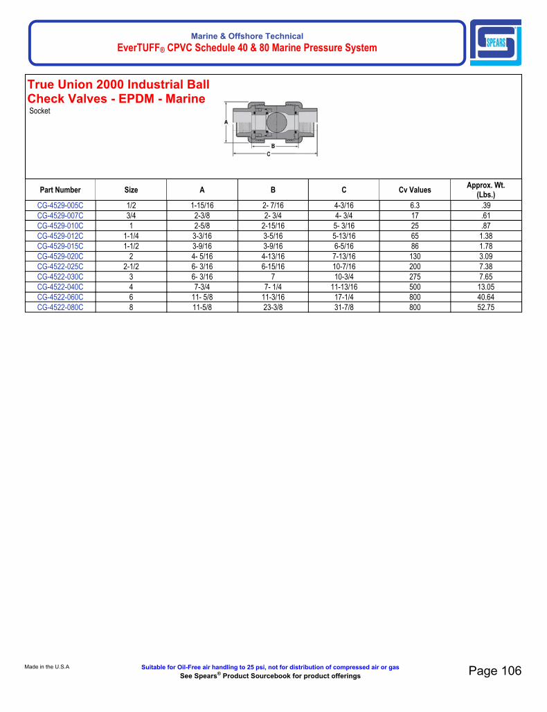
Marine & Offshore TechnicalEverTUFF® CPVC Schedule 40 & 80 Marine Pressure System
True Union 2000 Industrial Ball Check Valves - EPDM - MarineSocket
Made in the U.S.A. Suitable for Oil-Free air handling to 25 psi, not for distribution of compressed air or gasSee Spears® Product Sourcebook for product offerings Page 106
Part Number Size A B C Cv ValuesApprox. Wt.
(Lbs.)CG-4529-005C 1/2 1-15/16 2- 7/16 4-3/16 6.3 .39CG-4529-007C 3/4 2-3/8 2- 3/4 4- 3/4 17 .61CG-4529-010C 1 2-5/8 2-15/16 5- 3/16 25 .87CG-4529-012C 1-1/4 3-3/16 3-5/16 5-13/16 65 1.38CG-4529-015C 1-1/2 3-9/16 3-9/16 6-5/16 86 1.78CG-4529-020C 2 4- 5/16 4-13/16 7-13/16 130 3.09CG-4522-025C 2-1/2 6- 3/16 6-15/16 10-7/16 200 7.38CG-4522-030C 3 6- 3/16 7 10-3/4 275 7.65CG-4522-040C 4 7-3/4 7- 1/4 11-13/16 500 13.05CG-4522-060C 6 11- 5/8 11-3/16 17-1/4 800 40.64CG-4522-080C 8 11-5/8 23-3/8 31-7/8 800 52.75

Marine & Offshore TechnicalEverTUFF® CPVC Schedule 40 & 80 Marine Pressure System
True Union 2000 Industrial Ball Check Valves - EPDM - MarineSocket
(Continued)
True Union 2000 Industrial Ball Check Valves - FKM - MarineSocket
Page 107 Suitable for Oil-Free air handling to 25 psi, not for distribution of compressed air or gas Spears® Manufacturing CompanySee Spears® Product Sourcebook for product offerings
Part Number Size A B C Cv ValuesApprox. Wt.
(Lbs.)CG-4522-025C 2-1/2 6- 3/16 6-15/16 10-7/16 200 7.38CG-4522-030C 3 6- 3/16 7 10-3/4 275 7.65CG-4522-040C 4 7-3/4 7- 1/4 11-13/16 500 13.05CG-4522-060C 6 11- 5/8 11-3/16 17-1/4 800 40.64CG-4522-080C 8 11-5/8 23-3/8 31-7/8 800 52.75
Part Number Size A B C Cv ValuesApprox. Wt.
(Lbs.)CG-4539-005C 1/2 1-15/16 2- 7/16 4-3/16 6.3 .39CG-4539-007C 3/4 2-3/8 2- 3/4 4- 3/4 17 .61CG-4539-010C 1 2-5/8 2-15/16 5- 3/16 25 .88CG-4539-012C 1-1/4 3-3/16 3-5/16 5-13/16 65 1.39CG-4539-015C 1-1/2 3-9/16 3-9/16 6-5/16 86 1.81CG-4539-020C 2 4- 5/16 4-13/16 7-13/16 130 3.12CG-4532-025C 2-1/2 6- 3/16 6-15/16 10-7/16 200 7.43CG-4532-030C 3 6- 3/16 7 10-3/4 275 7.70CG-4532-040C 4 7-3/4 7- 1/4 11-13/16 500 13.11CG-4532-060C 6 11- 5/8 11-3/16 17-1/4 800 40.78CG-4532-080C 8 11-5/8 23-3/8 31-7/8 800 52.75

Marine & Offshore TechnicalEverTUFF® CPVC Schedule 40 & 80 Marine Pressure System
Sample Engineering SpecificationAll thermoplastic ball valves shall be 2000 Compact type manufactured to ASTM F1970 and constructed from CPVC Type IV, ASTM D 1784 Cell Classification 23447. All O-rings shall be EPDM or FKM. All valves shall have Safe-T-Shear® stem with O-ring stem seal. All handles shall be Polypropylene. All valves with EPDM elastomers shall be certified by NSF International for use with potable water. All 1/2" - 2" valves shall be pressure rated to 235 psi, for water @ 73°F, as manufactured by Spears®
Manufacturing Company. All CPVC Marine Compact Ball Valves shall be suitable for use with Spears® U.S. Coast Guard Approved piping systems only.
FeaturesEconomical, low profile quarter-turn shutoff valve is excellent for marine and many O.E.M applications. CPVC valves are available in IPS sizes 1/2" through 2" with socket connectors.
• New Actuator-Ready Body — Accepts Spears®
Improved Mini-Mount Actuator Mounting Kits • New Double O-ring Stem Seal• Schedule 80 Full-Port Design• Spears® Safe-T-Shear Stem• PTFE/HDPE Self Adjusting Floating Seats• EPDM or FKM O-ring Seals• Sizes 1/2"-2" Pressure Rated to 235 psi @ 73°F• EPDM valves NSF® Certified for Use with • Manufactured to ASTM F 1970
Optional Accessories*• Round Safety Handles• Stem Extension Kits• Square Operator Nuts• Multi Mount Valve/Actuation Mounting Kits• Mini-Mount Actuation Mounting Kits
Quick-View Valve Selection ChartValveSize
O-ringMaterial
CPVC Part Number PressureRatingSocket
1/2EPDM CG-6629-005C
235 psiNon-Shock
Water@73°F
(Flanged150 psi
Non-Shock)Water @73°F
FKM CG-6639-005C
3/4EPDM CG-6629-007C
FKM CG-6639-007C
1EPDM CG-6629-010C
FKM CG-6639-010C
1-1/4EPDM CG-6629-012C
FKM CG-6639-012C
1-1/2EPDM CG-6629-015C
FKM CG-6639-015C
2EPDM CG-6629-020C
FKM CG-6639-020C
Made in the U.S.A. Suitable for Oil-Free air handling to 25 psi, not for distribution of compressed air or gasSee Spears® Product Sourcebook for product offerings Page 108

Marine & Offshore TechnicalEverTUFF® CPVC Schedule 40 & 80 Marine Pressure System
Compact 2000 Ball Valves - EPDM - MarineSocket
Compact 2000 Ball Valves - FKM - MarineSocket
Page 109 Suitable for Oil-Free air handling to 25 psi, not for distribution of compressed air or gas Spears® Manufacturing CompanySee Spears® Product Sourcebook for product offerings
Part Number Size A B C D E Cv ValuesApprox. Wt.
(Lbs.)CG-6622-005C 1/2 1- 7/16 1- 1/4 3 1- 5/8 2- 1/2 42 .19CG-6622-007C 3/4 1-3/4 1- 1/2 3-1/2 2 3 87 .31CG-6622-010C 1 2- 1/16 1-11/16 3-15/16 2- 5/16 3-3/8 157 .46CG-6622-012C 1-1/4 2-9/16 2-1/8 4- 5/8 2-13/16 3-1/2 311 .71CG-6622-015C 1-1/2 2-15/16 2-1/2 5- 1/4 3- 1/16 3- 7/8 429 1.00CG-6622-020C 2 3-9/16 3 6 3- 3/4 4-15/16 768 1.63
Part Number Size A B C D E Cv ValuesApprox. Wt.
(Lbs.)CG-6632-005C 1/2 1- 7/16 1- 1/4 3 1- 5/8 2- 1/2 42 .19CG-6632-007C 3/4 1-3/4 1- 1/2 3-1/2 2 3 87 .31CG-6632-010C 1 2- 1/16 1-11/16 3-15/16 2- 5/16 3-3/8 157 .46CG-6632-012C 1-1/4 2-9/16 2-1/8 4- 5/8 2-13/16 3-1/2 311 .71CG-6632-015C 1-1/2 2-15/16 2-1/2 5-1/4 3-1/16 3-7/8 429 1.00CG-6632-020C 2 3-9/16 3 6 3- 3/4 4-15/16 768 1.63
USCG Application Only

Marine & Offshore TechnicalEverTUFF® CPVC Schedule 40 & 80 Marine Pressure System
Lever Handle
Gear Operated
Sample Engineering SpecificationAll thermoplastic valves shall be marine butterfly type constructed from CPVC Type IV Cell Classification 23447. All valve seats and O-rings shall be EPDM or FKM. Valves with EPDM seats and seals shall be listed by NSF International. Seat shall be a non-liner type interlocked to valve body. Bolt hole patterns shall conform to ANSI/ASME B16.5 Class 150. Disc shall be offset design with fully isolated Type 316L stainless steel stem and Type 316 stainless steel hardware. Lever operated valves shall be equipped with high impact polypropylene handle having built-in lockout capability. Valves shall be pressure rated at 150psi for water @ 73° F, with a Limited Lifetime Warranty as manufactured by Spears® Manufacturing Company. CPVC marine butterfly valves 1-1/2" through 6" shall be type approved by the American Bureau of Shipping (ABS). CPVC marine butterfly valves 1-1/2" through 12" shall be suitable for use with Spears® U.S. Coast Guard approved piping systems.
Standard Butterfly Value FeaturesSpears® patented marine Butterfly Valve design departs from traditional liner-seat type valve to eliminate seat creep, reduce operating torque and provide positive seal-off. Ideally suited for flow control or throttling, this high-performance valve is offered with a full variety of options for greater application versatility in marine and chemical processing applications. Available in IPS sizes 1-1/2" - 12" in Standard Lug style.• Special off-set Disc lifts quickly from seat to reduce wear and
reduce operating torque• Patented Limited Contact Seat design provides free travel -
eliminates seat creep, extrusion and wear. Field replaceable without full valve disassembly
• Interlocking Body & Seat prevents wash-out or blow-out• Fully Isolated Solid Type 316L Stainless Steel Stem• Reversible High Impact Polypropylene Lever Handle with
7-Position stops & Built-in Lockout (standard handle on 1-1/2" – 8" valves; not available on 10" & larger valves)
• High Efficiency Submersible Gear Operator with 316 Stainless Steel Acme Screw and CPVC Housing. Polypropylene Handwheel, and Built-in Position Indicator (available for all sizes; standard on 10" & larger valves)
• Standard valve through 12" accepts field-installable Lug Inserts Set option
• Pressure Rated to 150 psi @ 73°F including Dead-End Service through 12"
• ANSI/ASME B16.5 Class 150 Bolt Pattern• Valves with EPDM Seals & Seats are NSF® Certified for
Potable water use
Optional Accessories• Stem Extension Kit• PTFE Seat Sleeve• Lever Handle Kit (standard on 1-1/2" - 8" valves)• Gear Operator Kit (standard on 10" & larger valves)• T-Handle Kit• Field Installable Lug Insert Sets (for Standard valve)• Speed Handle (for gear operated valves)• 2" Square/T-Style Operator Nut (for gear operated valves)• Chainwheel Operator Kit (for gear operated valves)• Positive Stem Stop (for gear operated valves)
Made in the U.S.A. Suitable for Oil-Free air handling to 25 psi, not for distribution of compressed air or gasSee Spears® Product Sourcebook for product offerings Page 110

Marine & Offshore TechnicalEverTUFF® CPVC Schedule 40 & 80 Marine Pressure System
Page 111 Suitable for Oil-Free air handling to 25 psi, not for distribution of compressed air or gas Spears® Manufacturing CompanySee Spears® Product Sourcebook for product offerings
Standard & Gear Operator Style Quick-View Valve Selection Chart
Valve Size O-ring MaterialCPVC Part Number
PressureWith Level Handle With Gear Operator
1-1/2EPDM CG-722311-015C N/A
150 psiNon-Shock
Water @ 73°F
FKM CG-723311-015C N/A
2EPDM CG-722311-020C N/A
FKM CG-723311-020C N/A
2-1/2EPDM CG-722311-025C N/A
FKM CG-723311-025C N/A
3EPDM CG-722311-030C N/A
FKM CG-723311-030C N/A
4EPDM CG-722311-040C N/A
FKM CG-723311-040C N/A
6EPDM CG-722311-060C N/A
FKM CG-723311-060C N/A
8EPDM CG-722311-080C N/A
FKM CG-723311-080C N/A
10EPDM N/A CG-722321-100C
FKM N/A CG-723321-100C
12EPDM N/A CG-722321-120C
FKM N/A CG-723321-120C
Temperature Pressure RatingSystem Operating
Temperature °F (°C)100(38)
110(43)
120(49)
130(54)
140(60)
150(66)
160(71)
170(77)
180(82)
190(88)
200(93)
210(99)
Valve PressureRating psi (MPa)
CPVC150
(1.03)140(.97)
130(.90)
120(.83)
110(.76)
100(.70)
90(.62)
80(.55)
70(.48)
60(.41)
50(.34)
-0-(-0-)
1-1/2" - 6" ABS Approved1-1/2" - 12" U.S. Coast Guard Applications
Note: Flanged valves have a base pressure rating of 150 psi.

Marine & Offshore TechnicalEverTUFF® CPVC Schedule 40 & 80 Marine Pressure System
No Component Qty. Material
1 Body 1 CPVC
2 Stem Bearing 1 PTFE/GFPP
3 Seal Carrier 1 CPVC/PP
4 Seat 1 EPDM, FKM
5 Disc 1 CPVC/PP
6 Disc O-ring 2 EPDM, FKM
7 Stem Bushing 1 PTFE/GFPP
8 Stem Bushing O-ring 2 EPDM, FKM
9 Stem O-ring 2 EPDM, FKM
10 Stem Washer - Hex 1 PTFE
11 Stem Washer - Slot* 1-2 SS 316
12 Stem Washer - Round 1 PTFE/GFPP
13 Stem 1 SS 316
14 Stem Nut 1 CPVC
15 Handle Body 1 PP
16 Handle Grip 1 GFPVC
17 Grip Pin 1 PP
18 Lock Pin 1 PP
19 Handle Lock 1 GFPVC
20 Handle Spring 1 SS 316
21 Handle Cover 1 PP
22 Hex Bolt 1 SS 316
23 Flat Washer 1 SS 316
24 Handle Bushing 1 GFPVC
25 Disc Timing Stop 1 CPVC
26 Lug Insert 1 SS/Zinc Plated Steel
27 Gear Operator Assembly 1 Cast Aluminum
28 Hand Wheel 1 PP
Made in the U.S.A. Suitable for Oil-Free air handling to 25 psi, not for distribution of compressed air or gasSee Spears® Product Sourcebook for product offerings Page 112
Replacement Parts for 1-1/2" - 12" CPVC Standard Marine BFV Valves

Marine & Offshore TechnicalEverTUFF® CPVC Schedule 40 & 80 Marine Pressure System
Page 113 Suitable for Oil-Free air handling to 25 psi, not for distribution of compressed air or gas Spears® Manufacturing CompanySee Spears® Product Sourcebook for product offerings
Standard Lug Style Marine Butterfly Valve Dimensions
DimensionsNominal
Size
PressureRating1
(psi)A B Standard
Lug Mount C D E F G Approx. Wt.(lbs)
1-1/2 150 8-3/16 1-9/16 5 5-11/16 9 4-1/8 11-31/32 2.592 150 9-5/16 1-15/16 6 6-5/16 9 4-3/4 12-13/16 3.33
2-1/2 150 9-15/16 2-1/16 6-3/4 6-9/16 9 5 13-7/16 4.103 150 11-1/2 2-3/16 7-1/2 7-3/4 12 5-1/2 14-21/32 6.284 150 13 2-5/16 9 8-1/2 12 6-1/4 15-15/16 7.906 150 16-3/8 2-13/16 11 10-7/8 13-15/16 8-9/16 19-9/16 13.298 150 18-5/8 3 13-1/2 11-7/8 13-15/16 9-9/16 20-9/16 19.64
10 150 N/A 3-5/16 16 N/A N/A 11 24-11/16 33.4212 150 N/A 3-9/16 19 N/A N/A 12 27-3/16 46.93
NominalSize H I J K L M N O P
1-1/2 9-3/16 6-9/16 2-1/4 8 8-7/8 4-3/8 4-3/8 2 2-3/82 9-13/16 6-9/16 2-1/4 8 8-7/8 4-3/8 4-3/8 2 2-3/8
2-1/2 10-1/32 6-9/16 2-1/4 8 8-7/8 4-3/8 4-3/8 2 2-3/83 10-7/8 6-5/8 2-3/4 8 9-1/4 4-7/8 4-11/16 2 2-11/164 11-7/16 6-5/8 2-3/4 8 9-1/4 4-7/8 4-11/16 2 2-11/166 14 6-5/8 2-3/4 8 9-1/4 4-7/8 4-11/16 2 2-11/168 13-23/32 6-5/8 2-3/4 8 9-1/4 4-7/8 4-11/16 2 2-11/16
10 16-11/16 7-7/16 3-5/8 7-15/16 10-7/8 6-13/16 6-5/16 2-3/8 2-1/812 17-11/16 7-7/16 3-5/8 7-15/16 10-7/8 6-13/16 6-5/16 2-3/8 2-1/8
1: Maximum Internal Pressure Rating @ 73°F

Marine & Offshore TechnicalEverTUFF® CPVC Schedule 40 & 80 Marine Pressure System
Note: Hex = Standard, Lug Style ValvesSQR = Wafer Style Valves
Made in the U.S.A. Suitable for Oil-Free air handling to 25 psi, not for distribution of compressed air or gasSee Spears® Product Sourcebook for product offerings Page 114
CV Values & Operating Torque
Valve SizeCV
1 Degrees Open Operating2
Torque(in.-lbs.)15° 30° 45° 60° 75° 90°
1-1/2 2 8 20 36 61 81 100
2 3 11 27 49 82 109 110
2-1/2 5 19 48 86 144 192 206
3 9 35 86 155 259 345 360
4 10 41 103 185 308 411 420
6 28 113 281 506 844 1125 720
8 56 225 562 1012 1687 2249 1200
10 111 444 1110 1998 3330 4440 1320
12 158 631 1577 2839 4732 6309 1920
1: Gallons per minute at 1 psi pressure drop.2: Operating torque for large diameter valves varies significantly with system operating pressure, flow direction and velocity.
Contact Spears® for torque requirement based on application.
Actuator Mounting Dimensions For Custom Actuation
SizeBolt HoleSpacing
Bolt Hole Diameter
Bolt Circle Diameter
Hex Square Stem Height+.000 -.006 +.000 -.002
Standard Wafer Standard Wafer Standard Wafer Standard Wafer Standard Wafer
1-1/2 1.95 N/A .34 N/A 2.75 N/A .375 N/A .75 N/A
2 1.95 2.47 .34 .40 2.75 3.50 .500 .375 .75 1.30
2-1/2 1.95 2.47 .34 .40 2.75 3.50 .500 .375 .75 1.34
3 2.65 2.47 .41 .40 3.75 3.50 .563 .500 1.00 1.34
4 2.65 2.47 .41 .40 3.75 3.50 .625 .500 1.04 1.37
6 3.17 2.83 .41 .40 4.48 4.00 .875 .750 1.27 1.80
8 3.17 3.17 .41 .40 4.48 4.48 1.000 .875 1.29 1.96
10 3.54 3.54 .41 .41 5.00 5.00 1.125 1.000 1.38 1.38
12 3.54 3.54 .41 .41 5.00 5.00 1.250 1.000 1.38 1.38

Marine & Offshore TechnicalEverTUFF® CPVC Schedule 40 & 80 Marine Pressure System
CAUTION: Flange must be installed on side of valve opposite the hex nut recesses for Single-Side Installation as illustrated.
(Flange, bolts, nuts, washers and gaskets not included.Lug inserts may be ordered separately.)
Page 115 Suitable for Oil-Free air handling to 25 psi, not for distribution of compressed air or gas Spears® Manufacturing CompanySee Spears® Product Sourcebook for product offerings
General Installation InformationSpears® CPVC Marine Butterfly Valves are designed for system connections either between two flanges, or with single-side (flange one-side only) connection for dead-end service using lug style valves. Lug Insert Valves require attention to flow direction; True Lug valves may be installed either direction. The valve handle (or gear operator) is reversible 180° for either left or right side operation. Spears® Butterfly Valves are designed for installation with user supplied 1/8" full-faced gaskets, hex bolts, nuts and flat washers. Caution: Spears® Butterfly Valves are designed for use with flanges or flanged equipment having minimum waterway inside diameter no less than that of Schedule 80 PVC pipe (ASTM D 1785). Use of smaller inside diameter flange connections may result in obstruction and damage to the valve disc.
CPVC Marine Butterfly Valve Torque and Hardware Requirements
Valve Size(in.)
No. of
Bolt Holes
Bolt Torque (ft.- lb.)
Standard Valve Valve with Lug InsertsBolt Lengths1 (in.) Bolt
Diameter(in.)
BoltThreadsper inch
FlatWasher
O.D. (in.)
Bolt Lengths1 (in.) BoltDiameter
(in.)
LugThreadsper inch
FlatWasherO.D. (in.)
SingleSide
DualFlange3
SingleSide
2ndFlange2
1-1/2 4 12 3-1/4 4-1/4 1/2 13 1-3/8 1-3/4 1-1/2 1/2 13 1-3/82 4 25 3-3/4 4-3/4 5/8 11 1-3/4 2 1-3/4 5/8 11 1-3/4
2-1/2 4 25 4-1/4 5-1/4 5/8 11 1-3/4 2-1/4 2 5/8 11 1-3/43 4 25 4-1/4 5-1/2 5/8 11 1-3/4 2-1/4 2 5/8 11 1-3/44 8 25 4-1/2 5-3/4 5/8 11 1-3/4 2-1/2 2 5/8 11 1-3/46 8 40 5-1/4 6-3/4 3/4 10 2 3-1/4 2-1/4 3/4 10 28 8 40 5-3/4 7-1/4 3/4 10 2 3-3/4 2-1/4 3/4 10 210 12 64 6-1/2 8-1/4 7/8 9 2-1/4 4 3 7/8 9 2-1/412 12 95 6-3/4 8-1/2 7/8 9 2-1/4 4-1/4 3 7/8 9 2-1/4
1: Minimum bolt lengths based on use of Spears® flanges, 1/8" full faced gaskets, standard S.A.E. hex bolts and Standard Plate Series flat washers.2: Specified bolt lengths are maximum allowable for maintaining proper clearance in initial Single-Side installation with Lugs where anticipated 2nd Flange installation option is to be
retained without removal of valve.3: Minimum bolt length through 2-flanges, 2-gaskets, 2-flat washers and 1-valve body.
Single-Side (flange one side) Installation Using Standard Valve with Lug Inserts (forfield installable Insert Sets)

Marine & Offshore TechnicalEverTUFF® CPVC Schedule 40 & 80 Marine Pressure System
Sample Engineering SpecificationAll thermoplastic marine valves shall be Wafer Butterfly type constructed from CPVC Type IV Cell Classification 23447 per ASTM D1784. All valve seats and O-rings shall be EPDM or FKM Seat shall be a non-liner type mounted to the valve disc. All valves shall have built-in Santoprene™ Thermoplastic Elastomer (TPE) flange gaskets. Wafer style valves shall be for mounting between two flanges having bolt hole pattern that conform to ANSI/ ASME B16.5 CL 150. Disc shall be offset design with Type 316L stainless steel stem. Stem shall be isolated from the process medium for dry operation. Lever operated valves shall be equipped with high impact polypropylene handle having 7-position stops and built-in lockout capability. Valves shall be pressure rated at 150 psi for water at 73°F, with a Limited Lifetime Warranty as manufactured by Spears®
Manufacturing Company. CPVC Marine Wafer Butterfly Valves 2” through 6” shall be type approved by the American Bureau of Shipping (ABS). CPVC Marine Wafer Butterfly Valves 2” through 12” shall be suitable for use with Spears® U.S. Coast Guard approved piping systems.
FeaturesSpears® CPVC Marine Wafer Butterfly Valve is a multi-featured design incorporating laying lengths that allow direct replacement of common Cast Iron valves such as Keystone Model 228 and Bray Series 30 Butterfly Valves. Wafer Valves feature built-in Santoprene™ Thermoplastic Elastomer (TPE) flange gaskets, easy operating disc-mounted seat, and fully isolated stem design. Available in sizes 2" through 12", with choice of EPDM or FKM Seats on CPVC Valves.
CPVC Marine Wafer Butterfly Valves Pressure Rated to 150 psi for water @ 73°F(23° C)
Wafer Butterfly Quick-View Selection Chart
ValveSize
O-ringMaterial
CPVC Part NumberPressure
Ratingw/LeverHandle
w/GearOperator
2EPDM CG-752311-020C N/A
150 psiShock Water
@ 73 °F
FKM CG-753311-020C N/A
2-1/2EPDM CG-752311-025C N/A
FKM CG-753311-025C N/A
3EPDM CG-752311-030C N/A
FKM CG-753311-030C N/A
4EPDM CG-752311-040C N/A
FKM CG-753311-040C N/A
6EPDM CG-752311-060C N/A
FKM CG-753311-060C N/A
8EPDM CG-752311-080C N/A
FKM CG-753311-080C N/A
10EPDM N/A CG-752321-100C
FKM N/A CG-753321-100C
12EPDM N/A CG-752321-120C
FKM N/A CG-753321-120C
General Installation InformationSpears® CPVC Marine Wafer Butterfly Valves are designed for system connections between two flanges having ANSI B16.5 Class 150 bolt hole patterns. The valve handle (or gear operator) is reversible 180° for either left or right side operation. Wafer Butterfly Valves have built-in flange gaskets and are designed for installation with user supplied hex bolts, nuts and flat washers. The valve must be positioned with gasket areas evenly located between mating flange sealing surfaces. Valve Bolt Specification bolt lengths in table below are minimums based on use of two (2) Spears® flanges, valve with built-in gaskets, standard S.A.E. hex bolts and Standard Plate "W" Series flat washers. Caution: Spears® CPVC Marine Wafer Butterfly Valves are designed for use with flanges or flanged equipment having minimum waterway inside diameter no less than that of Schedule 80 CPVC pipe (ASTM D 1785). Use of smaller inside diameter flange connections may result in obstruction and damage to the valve disc and seat.
• Chemical & Corrosion Resistant CPVC Construction• Special Designed Laying Lengths for Direct Replacement of
Common Cast Iron Butterfly Valves• Built-in Santoprene Thermoplastic Elastomer (TPE) gaskets on
Valve Flanges• Easy Operating Disc Mounted Seat in Choice of EPDM, or
FKM• Fully Isolated (Dry) Solid Type 316L Stainless Steel Stem• Reversible High Impact Polypropylene Lever Handle with
7-Position Stops and Built-in Lockout Capability• Optional High Efficiency Submersible Gear Operator with 316
Stainless Steel Acme screw and CPVC Housing, Polypropylene Handwheel and Built-in Position Indicator
• Compatible with ANSI/ASME B16.5 Class 150 Bolt Pattern Flanges
Made in the U.S.A. Suitable for Oil-Free air handling to 25 psi, not for distribution of compressed air or gasSee Spears® Product Sourcebook for product offerings Page 116

Marine & Offshore TechnicalEverTUFF® CPVC Schedule 40 & 80 Marine Pressure System
Page 117 Suitable for Oil-Free air handling to 25 psi, not for distribution of compressed air or gas Spears® Manufacturing CompanySee Spears® Product Sourcebook for product offerings
CPVC Marine Wafer Butterfly Valve Bolt Specifications & DimensionsValve Size Bolt Diameter (in.) Bolt Length (in.) No. of Bolt Holes
2 5/8 4-1/2 42-1/2 5/8 5 4
3 5/8 5 44 5/8 5-1/2 46 3/4 6 48 3/4 6-1/2 4
10 7/8 7 412 7/8 7-1/2 4
Size A B C D E FBolt Circle Diameter2 No.
ofBolts3
BoltHoleDia.
DiscClearance
Dia.
Approx.Wt. (lbs.) ANSI PN16 (mm) PN10
ISO DIN (mm)2 8-9/16 1-11/16 3-3/4 5-9/16 9 4 4-3/4 125 125 4 13/16 1-1/2 2.66
2-1/2 9-9/16 1-13/16 4-1/2 6-1/16 9 4-1/2 5-1/2 145 145 4 13/16 1-15/16 3.183 10-1/8 1-13/16 5 6-7/16 9 4-7/8 6 160 160 4 7/8 2-3/4 3.604 11-3/16 2-1/16 6-1/4 6-15/16 9 5-3/8 7-1/2 180 180 4 (8) 15/16 3-7/16 3.806 14-3/4 2-1/4 8-9/16 9-1/4 12 7-1/16 9-1/2 240 240 4 (8) 7/8 5-7/16 6.258 17-1/2 2-5/8 10-3/4 10-11/16 13-15/16 8-3/8 11-3/4 NA 295 4 (8) 15/16 7-3/16 14.67
101 NA 2-9/16 12-7/8 NA NA 10-11/16 14-1/4 355 350 4 (12) 1-1/8 9-3/16 26.84121 NA 3-1/16 15-9/16 NA NA 11-11/16 17 410 400 4 (12) 1-1/2 11-1/8 32.46
1: 10" and 12" valves are only available with gear operator.2: Holes are oversized to accommodate different bolt patterns — ASME/ANSI B16.1 — Cast Iron Pipe Flanges and Flanged Fittings - Class 150 Bolt Patterns; PN10 &
PN16 = B54504 — Circular Flanges for Pipes, Valves and Fittings (PN - Designated); DIN = DIN8063 Part 4 — Pipe Joint Assemblies and Fittings for Unplasticized Polyvinyl Chloride (PVC-U) Pressure Pipe.
3: Valve is positioned with 4 of 8 required Flange Bolts in sizes 4 to 8 inches and 4 of 12 in sizes 10 and 12 inches.
Size G H I J K L M N O P2 12-1/8 9-1/16 6-9/16 2-1/4 8 8-7/8 4-3/8 4-3/8 2 2-3/8
2-1/2 13-1/8 9-9/16 6-9/16 2-1/4 8 8-7/8 4-3/8 4-3/8 2 2-3/83 13-29/32 10-1/4 6-5/8 2-3/4 8 9-1/4 4-7/8 4-11/16 2 2-11/164 15 10-23/32 6-5/8 2-3/4 8 9-1/4 4-7/8 4-11/16 2 2-11/166 18 12-1/2 6-5/8 2-3/4 8 9-1/4 4-7/8 4-11/16 2 2-11/168 20-1/2 13-5/8 6-5/8 2-3/4 8 9-1/4 4-7/8 4-11/16 2 2-11/1610 24-1/2 16-3/8 7-7/16 3-5/8 7-15/16 10-7/8 6-13/16 6-5/16 2-3/8 2-1/812 26-7/8 17-3/8 7-7/16 3-5/8 7-15/16 10-7/8 6-13/16 6-5/16 2-3/8 2-1/8
Temperature Pressure RatingSystem Operating
Temperature °F (°C)100(38)
110(43)
120(49)
130(54)
140(60)
150(66)
160(71)
170(77)
180(82)
190(88)
200(93
210(99)
Valve Pressure Rating psi (MPa) CPVC 150
(1.03)140(.97)
130(.90)
120(.83)
110(.76)
100(.70)
90(.62)
80(.55)
70(.48)
60(.41)
50(.34)
-0-(-0-)
2" - 6" ABS Approved2" - 12" U.S. Coast Guard Applications

Marine & Offshore TechnicalEverTUFF® CPVC Schedule 40 & 80 Marine Pressure System
Butterfly Valve - Standard - EPDM - MarineLever Handle
Butterfly Valve - Standard - EPDM - MarineGear Operator
Butterfly Valves - Standard - FKM - MarineLever Handle
Made in the U.S.A. Suitable for Oil-Free air handling to 25 psi, not for distribution of compressed air or gasSee Spears® Product Sourcebook for product offerings Page 118
Part Number Size A B C D E FBolt Circle
Dia.Bolt Size
No ofBolts
Approx. Wt.(Lbs.)
CG-722311-015C 1-1/2 8-3/16 1- 9/16 5 5-11/16 9 4-1/8 3- 7/8 1/2 4 2.59CG-722311-020C 2 9-5/16 1-15/16 6 6-5/16 9 4- 3/4 4- 3/4 5/8 4 3.74CG-722311-025C 2-1/2 9-15/16 2-1/16 6- 3/4 6-9/16 9 5 5- 1/2 5/8 4 4.10CG-722311-030C 3 11- 1/2 2-3/16 7- 1/2 7-3/4 12 5-1/2 6 5/8 4 6.17CG-722311-040C 4 13 2-5/16 9 8- 1/2 12 6- 1/4 7- 1/2 5/8 8 7.78CG-722311-060C 6 16-3/8 2-13/16 11 10- 7/8 13-15/16 8-9/16 9- 1/2 3/4 8 13.11CG-722311-080C 8 18- 5/8 3 13- 1/2 11-7/8 13-15/16 9-9/16 11- 3/4 3/4 8 19.46
1-1/2” - 6” ABS type approved 1-1/2” - 12 USCG applications
Part Number Size B C F G H I J K L M N O PBolt Circle
Dia.Bolt Size
No ofBolts
Approx. Wt.(Lbs.)
CG-722321-100C 10 3-5/16 16 11 24-11/16 16-11/16 7-9/16 3-5/8 7-15/16 10-7/8 6-13/16 6-5/16 2-3/8 2-1/8 14- 1/4 7/8 12 34.88CG-722321-120C 12 3-9/16 19 12 27-3/16 17-11/16 7-7/16 3-5/8 7-15/16 10-7/8 6-13/16 6-5/16 2-3/8 2-1/8 17 7/8 12 48.33
Part Number Size A B C D E FBolt Circle
Dia.Bolt Size
No ofBolts
Approx. Wt.(Lbs.)
CG-723311-015C 1-1/2 8-3/16 1- 9/16 5 5-11/16 9 4-1/8 3- 7/8 1/2 4 2.59CG-723311-020C 2 9-5/16 1-15/16 6 6-5/16 9 4- 3/4 4- 3/4 5/8 4 3.75CG-723311-030C 3 11- 1/2 2-3/16 7- 1/2 7-3/4 12 5-1/2 6 5/8 4 6.20

Marine & Offshore TechnicalEverTUFF® CPVC Schedule 40 & 80 Marine Pressure System
Butterfly Valve - Standard - EPDM - MarineLever Handle
(Continued)
Butterfly Valve - Standard - EPDM - MarineGear Operator
Butterfly Valves - Standard - FKM - MarineLever Handle
Page 119 Suitable for Oil-Free air handling to 25 psi, not for distribution of compressed air or gas Spears® Manufacturing CompanySee Spears® Product Sourcebook for product offerings
Part Number Size A B C D E FBolt Circle
Dia.Bolt Size
No ofBolts
Approx. Wt.(Lbs.)
CG-722311-040C 4 13 2-5/16 9 8- 1/2 12 6- 1/4 7- 1/2 5/8 8 7.78CG-722311-060C 6 16-3/8 2-13/16 11 10- 7/8 13-15/16 8-9/16 9- 1/2 3/4 8 13.11CG-722311-080C 8 18- 5/8 3 13- 1/2 11-7/8 13-15/16 9-9/16 11- 3/4 3/4 8 19.46
1-1/2” - 6” ABS type approved 1-1/2” - 12 USCG applications
Part Number Size B C F G H I J K L M N O PBolt Circle
Dia.Bolt Size
No ofBolts
Approx. Wt.(Lbs.)
CG-722321-100C 10 3-5/16 16 11 24-11/16 16-11/16 7-9/16 3-5/8 7-15/16 10-7/8 6-13/16 6-5/16 2-3/8 2-1/8 14- 1/4 7/8 12 34.88CG-722321-120C 12 3-9/16 19 12 27-3/16 17-11/16 7-7/16 3-5/8 7-15/16 10-7/8 6-13/16 6-5/16 2-3/8 2-1/8 17 7/8 12 48.33
Part Number Size A B C D E FBolt Circle
Dia.Bolt Size
No ofBolts
Approx. Wt.(Lbs.)
CG-723311-015C 1-1/2 8-3/16 1- 9/16 5 5-11/16 9 4-1/8 3- 7/8 1/2 4 2.59CG-723311-020C 2 9-5/16 1-15/16 6 6-5/16 9 4- 3/4 4- 3/4 5/8 4 3.75CG-723311-030C 3 11- 1/2 2-3/16 7- 1/2 7-3/4 12 5-1/2 6 5/8 4 6.20CG-723311-040C 4 13 2-5/16 9 8- 1/2 12 6- 1/4 7- 1/2 5/8 8 7.81CG-723311-060C 6 16-3/8 2-13/16 11 10- 7/8 13-15/16 8-9/16 9- 1/2 3/4 8 13.18CG-723311-080C 8 18- 5/8 3 13- 1/2 11-7/8 13-15/16 9-9/16 11- 3/4 3/4 8 25.58
1-1/2” - 6” ABS type approved 1-1/2” - 12 USCG applications

Marine & Offshore TechnicalEverTUFF® CPVC Schedule 40 & 80 Marine Pressure System
Butterfly Valve - Standard - FKM - MarineGear Operator
Wafer Butterfly Valves - EPDM - MarineLever Handle
Made in the U.S.A. Suitable for Oil-Free air handling to 25 psi, not for distribution of compressed air or gasSee Spears® Product Sourcebook for product offerings Page 120
Part Number Size B C F G H I J K L M N O PBolt Circle
Dia.Bolt Size
No ofBolts
Approx. Wt.(Lbs.)
CG-723321-100C 10 3-5/16 16 11 24-11/16 16-11/16 7-9/16 3-5/8 8 10-7/8 6-13/16 6-5/16 2-3/8 2-1/8 14- 1/4 7/8 12 35.01CG-723321-120C 12 3-9/16 19 12 27-3/16 17-11/16 7-9/16 3-5/8 7-15/16 10-7/8 6-13/16 6-5/16 2-3/8 2-1/8 17 7/8 12 47.93
Part Number Size A B C D E FBolt Circle
Dia.Bolt Size
No ofBolts
Approx. Wt.(Lbs.)
CG-752311-020C 2 8-9/16 1-11/16 3- 3/4 5- 9/16 9 4 4-3/4 5/8 4 2.68CG-752311-025C 2-1/2 9-9/16 1-13/16 4-1/2 6- 1/16 9 4- 1/2 5-1/2 5/8 4 3.18CG-752311-030C 3 10- 1/8 1-13/16 5 6- 7/16 9 4- 7/8 6 5/8 4 3.60CG-752311-040C 4 11-3/16 2- 1/16 6- 1/4 6-15/16 9 5- 3/8 7-1/2 5/8 4 3.81CG-752311-060C 6 14-3/4 2-1/4 8- 9/16 9-1/4 12 7-1/16 9-1/2 3/4 4 8.78CG-752311-080C 8 17-1/2 2-5/8 10- 3/4 10-11/16 13-15/16 8-3/8 11-3/4 3/4 4 14.67
2” - 6” ABS type approved 2” - 12 USCG applications

Marine & Offshore TechnicalEverTUFF® CPVC Schedule 40 & 80 Marine Pressure System
Wafer Butterfly Valve - Standard - MarineGear Operator
Wafer Butterfly Valves -FKM - MarineLever Handle
Page 121 Suitable for Oil-Free air handling to 25 psi, not for distribution of compressed air or gas Spears® Manufacturing CompanySee Spears® Product Sourcebook for product offerings
Part Number Size B C F G H I J K L M N O PBolt Circle
Dia.Bolt Size
No ofBolts
Approx. Wt.(Lbs.)
CG-752321-100C 10 2- 9/16 12- 7/8 10-11/16 24-1/2 16-3/8 7-7/16 2-5/8 7-15/16 10-7/8 6-13/16 6-5/16 2-3/8 2-1/8 14-1/4 7/8 4 28.29CG-752321-120C 12 3- 1/16 15- 9/16 11-11/16 26-7/8 17-3/8 7-7/16 3-5/8 7-15/16 10-7/8 6-13/16 6-5/8 2-3/8 2-1/8 17 7/8 4 33.91
Part Number Size A B C D E FBolt Circle
Dia.Bolt Size
No ofBolts
Approx. Wt.(Lbs.)
CG-753311-020C 2 8-9/16 1-11/16 3- 3/4 5- 9/16 9 4 4-3/4 5/8 4 2.68CG-753311-025C 2-1/2 9-9/16 1-13/16 4-1/2 6- 1/16 9 4- 1/2 5-1/2 5/8 4 3.19CG-753311-030C 3 10- 1/8 1-13/16 5 6- 7/16 9 4- 7/8 6 5/8 4 3.62CG-753311-040C 4 11-3/16 2- 1/16 6- 1/4 6-15/16 9 5- 3/8 7-1/2 5/8 4 3.83CG-753311-060C 6 14-3/4 2-1/4 8- 9/16 9-1/4 12 7-1/16 9-1/2 3/4 4 8.75CG-753311-080C 8 17-1/2 2-5/8 10- 3/4 10-11/16 13-15/16 8-3/8 11-3/4 3/4 4 14.67
2” - 6” ABS type approved 2” - 12 USCG applications

Marine & Offshore TechnicalEverTUFF® CPVC Schedule 40 & 80 Marine Pressure System & Marine Solvent Cement & Primer
Wafer Butterfly Valve - Standard - FKM - MarineGear Operator
CPVC Marine-24 Solvent Cement - Gray - MarineRequires primer
PRIMER-70 Purple Industrial Strength Primer - Marine
Made in the U.S.A. Suitable for Oil-Free air handling to 25 psi, not for distribution of compressed air or gasSee Spears® Product Sourcebook for product offerings Page 122
Part Number Size B C F G H I J K L M N O PBolt Circle
Dia.Bolt Size
No ofBolts
Approx. Wt.(Lbs.)
CG-753321-100C 10 2- 9/16 12- 7/8 10-11/16 24-1/2 16-3/8 7-7/16 3-5/8 7-15/16 10-7/8 6-13/16 6-5/16 2-3/8 2-1/8 14-1/4 7/8 4 28.28CG-753321-120C 12 3- 1/16 15- 9/16 11-11/16 26-7/8 17-3/8 7-7/16 3-5/8 7-15/16 10-7/8 11-13/16 11-5/16 2-3/8 2-1/8 17 7/8 4 33.78
Part Number SizeApprox. Wt.
(Lbs.)CG-MARINE24-030 Quart 2.29CG-MARINE24-040 Gallon 9.03
Part Number SizeApprox. Wt.
(Lbs.)PRIM70P-030 Quart 2.02PRIM70P-040 Gallon 7.94

Marine & Offshore Technical
Marine Solvent Cement & Primer
PRIMER-70 Clear Industrial Strength Primer - Marine
Page 123 Suitable for Oil-Free air handling to 25 psi, not for distribution of compressed air or gas Spears® Manufacturing CompanySee Spears® Product Sourcebook for product offerings
Part Number SizeApprox. Wt.
(Lbs.)PRIM70C-030 Quart 2.02PRIM70C-040 Gallon 7.94
Average Number of Joints per Quart of Solvent CementPipe Diameter 1/2" 3/4" 1" 1-1/2" 2" 3" 4" 6" 8" 10" 12"
Number of Joints 300 200 125 90 60 40 30 10 5 2-3 1-2
NOTE: These figures are based on laboratory tests. Due to many field variations, these should be used as a general guide only.