everlast€¦ · power tig ® series tig (gtaw) and mma (smaw) welders operator’s manual for...
TRANSCRIPT

1
EVERLAST
Power TIG ® Series
Tig (GTAW) and mma (smaw)
Welders
Operator ’ s Manual for PowerTig® AC/DC Welders
Includes Power i-Tig® DC Models
Safety, Setup and General Use Guide
Rev. 1 0518-09

2
Thank you for purchasing an everlast product. We ap-preciate your patronage and hope that you will enjoy years of use from our product. Please go directly to the Everlast website to register your unit and receive your warranty information. Your unit registration is important should any infor-mation such as product updates or recalls be issued. It is also important so that we may track your satis-faction with Everlast products and services. If you are unable to register by website, contact Everlast di-rectly through the consumer department at the main number. Your unit will be registered and warrantee will be issued and in full effect.

3
Serial number: __________________________ Model number: ____________________________ Date of Purchase___________________________
EVERLAST
Contact Information
Everlast consumer satisfaction email: [email protected]
Everlast Website: everlastwelders.com
Everlast Technical Support: [email protected]
Main toll free number: 1-877-755 WELD ( 9353 ) 9am—5pm PST M-F
11am-4pm PST Sat.
FAX: 1-650-588-8817
NOTES:

4
Table of contents
Section……………………………………………….Page General ...…………………………………………… Safety Precautions..………………………………. Introduction and Specifications………………… Know Your Machine……………………………….. 2.1 Panel Face and Functions…………………… 2.2 Lower Panel and functions….……………… Getting Started…………………………………….. 3.1 General Guidelines…………………………… 3.2 Shielding Gas Selection……………………… 3.3 Regulator/Flow meter Selection…………… 3.4 Regulator Connection………………………... 3.5 Regulator Adjustment……………………….. 3.6 Machine Setup…………………………………. 3.7 Tungsten Selection…………………………… 3.8 TIG Torch……………………………………….. 3.9 TIG Welding Principles and Guide………… 3.13 MMA (Stick Welding)………………………… Trouble Shooting……………………………………
5 6 9 19 19 22 23 23 2323 23 23 24 24 26 26 28 30
5
Everlast is dedicated to providing you with the best possible equipment and service to meet the demanding jobs that you have. We want to go beyond deliv-ering a satisfactory product to you. That is the reason we offer technical sup-port to assist you with your needs should an occasion occur. With proper use and care your product should deliver years of trouble free service. Safe operation and proper maintenance is your responsibility. We have compiled this operator’s manual, to instruct you in basic safety, op-eration and maintenance of your Everlast product to give you the best possible experience. Much of welding and cutting is based upon experience and com-mon sense. As thorough as this welding manual may be, it is no substitute for either. Exercise extreme caution and care in all activities related to welding or cutting. Your safety, health and even life depends upon it. While accidents are never planned, preventing an accident requires careful planning. Please carefully read this manual before you operate your Everlast unit. This manual is not only for the use of the machine, but to assist in obtaining the best performance out of your unit. Do not operate the unit until you have read this manual and you are thoroughly familiar with the safe operation of the unit. If you feel you need more information please contact Everlast Support. The warranty does not cover improper use, maintenance or consumables. Do not attempt to alter or defeat any piece or part of your unit, particularly any safety device. Keep all shields and covers in place during unit operation should an unlikely failure of internal components result in the possible presence of sparks and explosions. If a failure occurs, discontinue further use until mal-functioning parts or accessories have been repaired or replaced by qualified personnel. Note on High Frequency electromagnetic disturbances: Certain welding and cutting processes generate High Frequency (HF) waves. These waves may disturb sensitive electronic equipment such as televisions, radios, computers, cell phones, and related equipment. High Frequency may also interfere with fluorescent lights. Consult with an electrician if distur-bance is noted. Sometimes, improper wire routing or poor shielding may be the cause. HF can interfere with pacemakers. See EMF warnings in following safety sec-tion for further information. Always consult your physician before entering an area known to have welding or cutting equipment if you have a pacemaker.
General
6
SAFETY PRECAUTIONS
These safety precautions are for protection of safety and health. Failure to follow these guidelines may result in serious injury or death. Be careful to read and follow all cautions and warnings. Protect yourself and others.
Welding and cutting processes produce high levels of ultraviolet (UV) radiation that can cause severe skin burn and damage. There are other potential hazards involved with welding such as severe burns and respiratory related illnesses. Therefore ob-serve the following to minimize potential accidents and injury: Use appropriate safety glasses with wrap around shields while in the work area, even under welding helmets to protect your eyes from flying sparks and debris. When chip-ping slag or grinding, goggles and face shields may be required.
When welding or cutting, always use an approved shielding device, with the correct shade of filter installed. Always use a welding helmet in good condition. Discard any broken or cracked filters or helmets. Using broken or cracked filters or helmets can cause severe eye injury and burn. Filter shades of no less than shade 5 for cutting and no less than shade 9 for welding are highly recommended. Shades greater than 9 may be required for high amperage welds. Keep filter lenses clean and clear for maxi-mum visibility. It is also advisable to consult with your eye doctor should you wear contacts for corrective vision before you wear them while welding. Do not allow personnel to watch or observe the welding or cutting operation unless fully protected by a filter screen, protective curtains or equivalent protective equip-ment. If no protection is available, exclude them from the work area. Even brief expo-sure to the rays from the welding arc can damage unprotected eyes. Always wear hearing protection because welding and cutting can be extremely noisy. Ear protection is necessary to prevent hearing loss. Even prolonged low levels of noise has been known to create long term hearing damage. Hearing protection also further protects against hot sparks and debris from entering the ear canal and doing harm. Always wear personal protective clothing. Flame proof clothing is required at all times. Sparks and hot metal can lodge in pockets, hems and cuffs. Make sure loose clothing is tucked in neatly. Leather aprons and jackets are recommended. Suitable welding jackets and coats may be purchased made from fire proof material from welding supply stores. Discard any burned or frayed clothing. Keep clothing away from oil, grease and flammable liquids. Leather boots or steel toed leather boots with rubber bottoms are required for ade-quate foot protection. Canvas, polyester and other man made materials often found in shoes will either burn or melt. Rubber or other non conductive soles are necessary to help protect from electrical shock. Flame proof and insulated gauntlet gloves are required whether welding or cutting or handling metal. Simple work gloves for the garden or chore work are not sufficient. Gauntlet type welding gloves are available from your local welding supply companies. Never attempt to weld with out gloves. Welding with out gloves can result in serious burns and electrical shock. If your hand or body parts comes into contact with the arc of a plasma cutter or welder, instant and serious burns will occur. Proper hand protection is required at all times when working with welding or cutting machines!
7
SAFETY PRECAUTIONS
continued WARNING! Persons with pacemakers should not weld, cut or be in the welding area
until they consult with their physician. Some pacemakers are sensitive to EMF radiation and could severely malfunction while welding or while being in the vicinity of someone welding. Serious injury or death may occur!
Welding and plasma cutting processes generate electro-magnetic fields and radiation. While the effects of EMF radiation are not known, it is suspected that there may be some harm from long term exposure to electromagnetic fields. Therefore, certain pre-cautions should be taken to minimize exposure:
Lay welding leads and lines neatly away from the body.
Never coil cables around the body.
Secure cables with tape if necessary to keep from the body.
Keep all cables and leads on the same side the body.
Never stand between cables or leads.
Keep as far away from the power source (welder) as possible while welding.
Never stand between the ground clamp and the torch.
Keep the ground clamp grounded as close to the weld or cut as possible. Welding and cutting processes pose certain inhalation risks. Be sure to follow any guidelines from your chosen consumable and electrode suppliers regarding possible need for respiratory equipment while welding or cutting. Always weld with adequate ventilation. Never weld in closed rooms or confined spaces. Fumes and gases re-leased while welding or cutting may be poisonous. Take precautions at all times. Any burning of the eyes, nose or throat are signs that you need to increase ventilation.
Stop immediately and relocate work if necessary until adequate ventilation is ob-tained.
Stop work completely and seek medical help if irritation and discomfort persists.
WARNING! Do not weld on galvanized steel, stainless steel, beryllium, titanium, cop-
per, cadmium, lead or zinc without proper respiratory equipment and or ventilation.
WARNING! This product when used for welding or cutting produces fumes and
gases which contains chemicals known to the State of California to cause birth de-
fects and in some cases cancer. (California Safety and Health Code §25249.5 et seq.)
WARNING! Do not weld or cut around Chlorinated solvents or degreasing areas.
Release of Phosgene gas can be deadly. Consider all chemicals to have potential deadly results if welded on or near metal containing residual amounts of chemicals. Keep all cylinders upright and chained to a wall or appropriate holding pen. Certain regulations regarding high pressure cylinders can be obtained from OSHA or local regulatory agency. Consult also with your welding supply company in your area for further recommendations. The regulatory changes are frequent so keep informed. All cylinders have a potential explosion hazard. When not in use, keep capped and closed. Store chained so that overturn is not likely. Transporting cylinders incorrectly can lead to an explosion. Do not attempt to adapt regulators to fit cylinders. Do not use faulty regulators. Do not allow cylinders to come into contact with work piece or work. Do not weld or strike arcs on cylinders. Keep cylinders away from direct heat, flame and sparks.
8
SAFETY PRECAUTIONS
continued
WARNING! Electrical shock can kill. Make sure all electrical equipment is properly
grounded. Do not use frayed, cut or otherwise damaged cables and leads. Do not stand, lean or rest on ground clamp. Do not stand in water or damp areas while weld-ing or cutting. Keep work surface dry. Do not use welder or plasma cutter in the rain or in extremely humid conditions. Use dry rubber soled shoes and dry gloves when welding or cutting to insulate against electrical shock. Turn machine on or off only with gloved hand. Keep all parts of the body insulated from work, and work tables. Keep away from direct contact with skin against work. If tight or close quarters ne-cessitates standing or resting on work piece, insulate with dry boards and rubber mats designed to insulate the body from direct contact.
All work cables, leads, and hoses pose trip hazards. Be aware of their location and make sure all personnel in area are advised of their location. Taping or securing ca-bles with appropriate restraints can help reduce trips and falls.
WARNING! Fire and explosions are real risks while welding or cutting. Always keep
fire extinguishers close by and additionally a water hose or bucket of sand. Periodi-cally check work area for smoldering embers or smoke. It is a good idea to have someone help watch for possible fires while you are welding. Sparks and hot metal may travel a long distance. They may go into cracks in walls and floors and start a fire that would not be immediately visible. Here are some things you can do to reduce the possibility of fire or explosion:
Keep all combustible materials including rags and spare clothing away from area.
Keep all flammable fuels and liquids stored separately from work area.
Visually inspect work area when job is completed for the slightest traces of smoke or embers.
If welding or cutting outside, make sure you are in a cleared off area, free from
dry tender and debris that might start a forest or grass fire.
Do not weld on tanks, drums or barrels that are closed, pressurized or anything that held flammable liquid or material.
Metal is hot after welding or cutting! Always use gloves and or tongs when handling hot pieces of metal. Remember to place hot metal on fire-proof surfaces after han-dling. Serious burns and injury can result if material is improperly handled.
WARNING! Faulty or poorly maintained equipment can cause injury or death.
Proper maintenance is your responsibility. Make sure all equipment is properly main-tained and serviced by qualified personnel. Do not abuse or misuse equipment. Keep all covers in place. A faulty machine may shoot sparks or may have exploding parts. Touching uncovered parts inside machine can cause discharge of high amounts of electricity. Do not allow employees to operate poorly serviced equipment. Always check condition of equipment thoroughly before start up. Disconnect unit from power source before any service attempt is made and for long term storage or electrical storms. Further information can be obtained from The American Welding Society (AWS) that relates directly to safe welding and plasma cutting. Additionally, your local welding supply company may have additional pamphlets available concerning their products. Do not operate machinery until your are comfortable with proper operation and are able to assume inherent risks of cutting or welding.
9
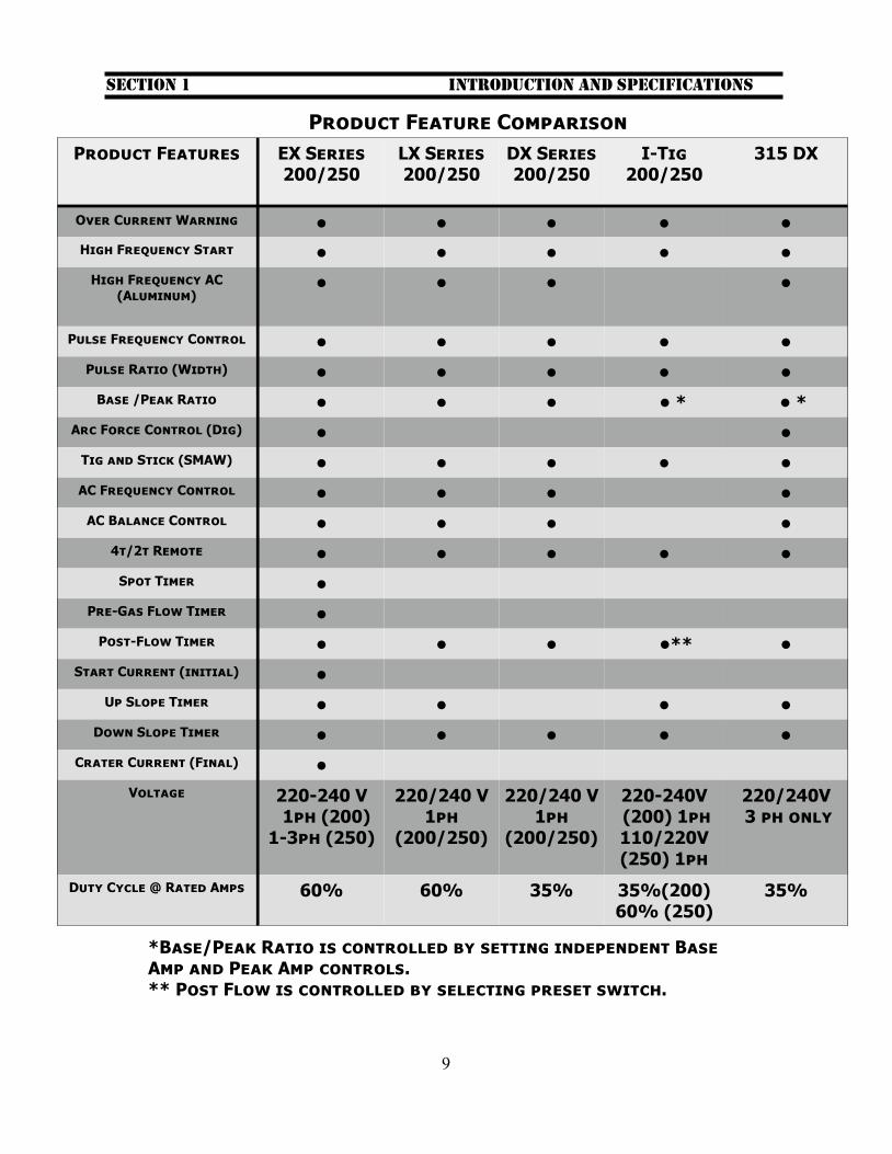
Product Feature Comparison
Introduction and Specifications Section 1
Product Features EX Series 200/250
LX Series 200/250
DX Series 200/250
I-Tig 200/250
315 DX
Over Current Warning • • • • •
High Frequency Start • • • • •
High Frequency AC (Aluminum)
• • • •
Pulse Frequency Control • • • • •
Pulse Ratio (Width) • • • • •
Base /Peak Ratio • • • • * • *
Arc Force Control (Dig) • •
Tig and Stick (SMAW) • • • • •
AC Frequency Control • • • •
AC Balance Control • • • •
4t/2t Remote • • • • •
Spot Timer •
Pre-Gas Flow Timer •
Post-Flow Timer • • • •** •
Start Current (initial) •
Up Slope Timer • • • •
Down Slope Timer • • • • •
Crater Current (Final) •
Voltage 220-240 V 1ph (200) 1-3ph (250)
220/240 V 1ph
(200/250)
220/240 V 1ph
(200/250)
220-240V (200) 1ph 110/220V(250) 1ph
220/240V 3 ph only
Duty Cycle @ Rated Amps 60% 60% 35% 35%(200) 60% (250)
35%
*Base/Peak Ratio is controlled by setting independent Base Amp and Peak Amp controls. ** Post Flow is controlled by selecting preset switch.
10
Introduction and Specifications Section 1
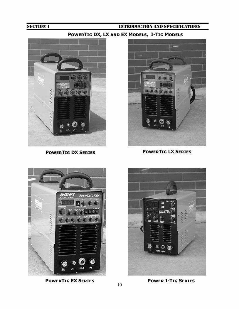
PowerTig DX, LX and EX Models, I-Tig Models
PowerTig DX Series PowerTig LX Series
PowerTig EX Series Power I-Tig Series
11
Introduction and Specifications Section 1
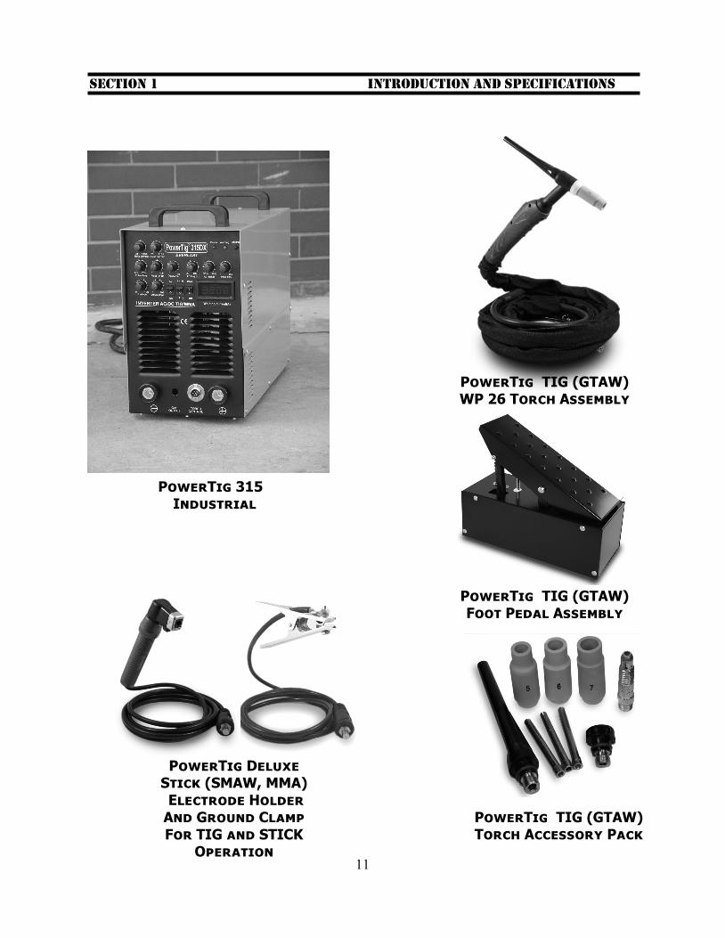
PowerTig 315 Industrial
PowerTig TIG (GTAW)WP 26 Torch Assembly
PowerTig TIG (GTAW) Foot Pedal Assembly
PowerTig Deluxe Stick (SMAW, MMA) Electrode Holder And Ground Clamp For TIG and STICK
Operation
PowerTig TIG (GTAW) Torch Accessory Pack
12
1.1 This manual has been compiled to give an overview of operation and is designed to offer information centered around safe, practical use of the machine. It is not in-tended to teach welding technique. All suggestions and techniques given are ap-proximations and should be used as a gen-eral guide only. 1.2 To ensure that your Everlast product is in top condition, carefully inspect unit for damage upon opening the box, looking for damage on the surface of the unit and to the machine itself and all its accessories. Do this immediately upon receipt of prod-uct. Any damage issues must be resolved right away. It is further recommended that the product be tested at the same time for proper operation, even if it is to be stored for a while. Check to make sure all pas-sages, connections and fittings are clear of any packing material or other obstruction. Record the serial number on the page pro-vided in this manual. Include purchase date for warranty reference. Serial numbers are located on the rear of the machine. 1.3 The PowerTig (includes I– Tig) units are used daily in the industry performing day to day fabrication and repair activities. The exceptional arc characteristics are provided by the inverter based technology that employs the use of reliable IGBT tran-sistors technology from Germany. Light-weight inverters allow a machine to be finely tuned for precise arc characteristics, while consuming less power than the lar-ger transformer based machines. Power-Tig units allow non-contact starts, eliminat-ing the problem of tungsten contamination. Depending upon the unit, precise control of the welding arc is allowed through the adjustments available on the panel face. The independent controls allow for a virtu-ally limitless number of configurations to suit every type metal and weld condition encountered. The use of High Frequency arc starting in AC and DC modes, greatly simplifies the TIG(GTAW) process.
1.4 Be careful to observe duty cy-cles of the machine posted in this manual and on the machine itself.
A duty cycle is a rating of percentage of time out of 10 minutes the machine can be used at the rated power setting . Over-heating may occur if the duty cycle is ex-ceeded. On multi-voltage, multi-phased machines, note that the rated duty cycle will change. 1.5 The unit should be stored in a dry place for long term storage. Humid/wet conditions can contribute to the eventual decay of the circuitry in the machine. For safety reasons, do not use this machine directly in the rain or with soaked clothing or protective gear. 1.6 Use only the provided handles to lift the unit. Do not suspend by cables or chains or use fork trucks to lift the units. If neces-sary, use two people to carry the unit. 1.7 Make sure that the units cooling fan and exhaust vents are kept free of obstruc-tion. Before every operation, inspect the unit for unexpected obstructions such as insect and rat nests. From time to time, a cleaning of the machine with low pressure air and a small plastic bristle brush is nec-essary to ensure long life. On these occa-sions only, unplug unit and remove cover to access interior. Concentrate efforts on aluminum heat sinks and panel vents to remove dust and dirt. 1.8 Refer to the following pages to locate your particular unit and its specifications. Note that product specifications are sub-ject to change without notice due to prod-uct improvements. If any additional infor-mation is needed contact Everlast. Sche-matics are not offered due to the proprie-tary information that they contain. How-ever, simple wiring diagrams may be ob-tained for basic diagnosis and may be ob-tained from technical support.
Introduction and Specifications Section 1
13
Introduction and Specifications Section 1
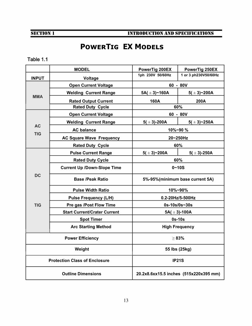
PowerTig EX Models
Table 1.1
MODEL PowerTig 200EX PowerTig 250EX
INPUT Voltage 1ph 230V 50/60Hz 1 or 3 ph230V50/60Hz
Open Current Voltage 60 - 80V
MMA Welding Current Range 5A( ± 3)~160A 5( ± 3)~200A
Rated Output Current 160A 200A
Rated Duty Cycle 60%
Open Current Voltage 60 - 80V
AC Welding Current Range 5( ± 3)-200A 5( ± 3)~250A
AC balance 10%~90 %
TIG
AC Square Wave Frequency 20~250Hz
Rated Duty Cycle 60%
Pulse Current Range 5( ± 3)~200A 5( ± 3)-250A
Rated Duty Cycle 60%
DC
Current Up /Down-Slope Time 0~10S
Base /Peak Ratio 5%-95%(minimum base current 5A)
Pulse Width Ratio 10%~90%
Pulse Frequency (L/H) 0.2-20Hz/5-500Hz
TIG Pre gas /Post Flow Time 0s-10s/0s~30s
Start Current/Crater Current 5A( ± 3)-100A
Spot Timer 0s-10s
Arc Starting Method High Frequency
Power Efficiency ≥ 83%
Weight 55 lbs (25kg)
Protection Class of Enclosure IP21S
Outline Dimensions 20.2x8.6xx15.5 inches (515x220x395 mm)
14
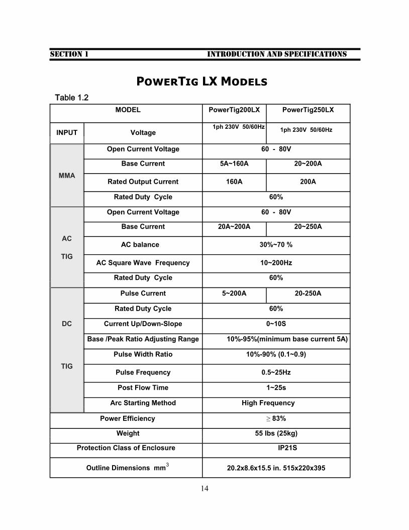
MODEL PowerTig200LX PowerTig250LX
INPUT Voltage 1ph 230V 50/60Hz
1ph 230V 50/60Hz
Open Current Voltage 60 - 80V
MMA
Base Current 5A~160A 20~200A
Rated Output Current 160A 200A
Rated Duty Cycle 60%
Open Current Voltage 60 - 80V
AC
Base Current 20A~200A 20~250A
AC balance 30%~70 %
TIG
AC Square Wave Frequency 10~200Hz
Rated Duty Cycle 60%
Pulse Current 5~200A 20-250A
Rated Duty Cycle 60%
DC
Current Up/Down-Slope 0~10S
Base /Peak Ratio Adjusting Range 10%-95%(minimum base current 5A)
Pulse Width Ratio 10%-90% (0.1~0.9)
TIG
Pulse Frequency 0.5~25Hz
Post Flow Time 1~25s
Arc Starting Method High Frequency
Power Efficiency ≥ 83%
Weight 55 lbs (25kg)
Protection Class of Enclosure IP21S
Outline Dimensions mm3 20.2x8.6x15.5 in. 515x220x395
Introduction and Specifications Section 1
Table 1.2
PowerTig LX Models
15
Introduction and Specifications Section 1
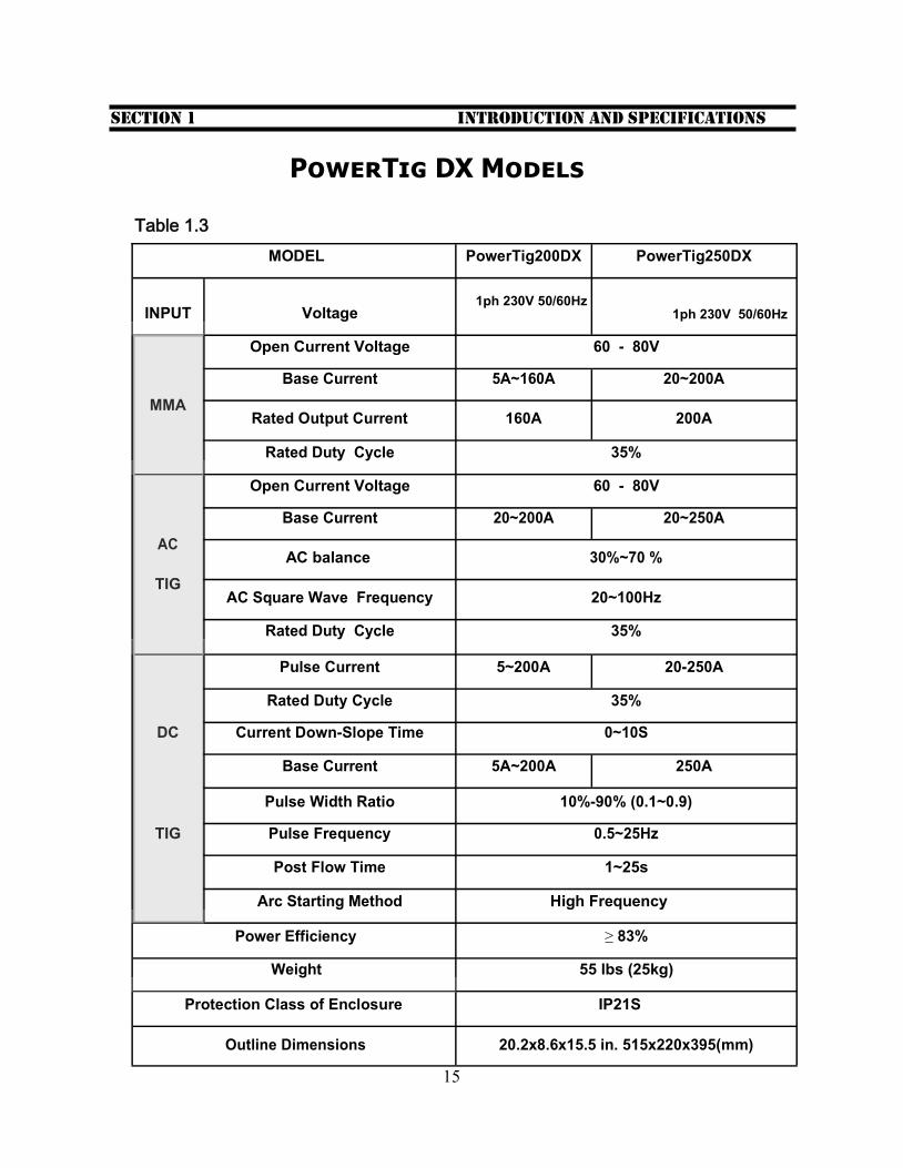
MODEL PowerTig200DX PowerTig250DX
INPUT Voltage 1ph 230V 50/60Hz
1ph 230V 50/60Hz
Open Current Voltage 60 - 80V
MMA
Base Current 5A~160A 20~200A
Rated Output Current 160A 200A
Rated Duty Cycle 35%
Open Current Voltage 60 - 80V
AC
Base Current 20~200A 20~250A
AC balance 30%~70 %
TIG
AC Square Wave Frequency 20~100Hz
Rated Duty Cycle 35%
Pulse Current 5~200A 20-250A
Rated Duty Cycle 35%
DC Current Down-Slope Time 0~10S
Base Current 5A~200A 250A
Pulse Width Ratio 10%-90% (0.1~0.9)
TIG Pulse Frequency 0.5~25Hz
Post Flow Time 1~25s
Arc Starting Method High Frequency
Power Efficiency ≥ 83%
Weight 55 lbs (25kg)
Protection Class of Enclosure IP21S
Outline Dimensions 20.2x8.6x15.5 in. 515x220x395(mm)
PowerTig DX Models
Table 1.3
16
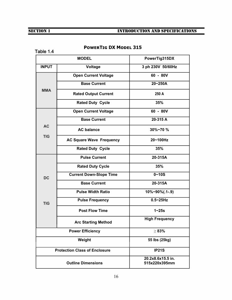
MODEL PowerTig315DX
INPUT Voltage 3 ph 230V 50/60Hz
Open Current Voltage 60 - 80V
MMA
Base Current 20~250A
Rated Output Current 250 A
Rated Duty Cycle 35%
Open Current Voltage 60 - 80V
AC
Base Current 20-315 A
AC balance 30%~70 %
TIG
AC Square Wave Frequency 20~100Hz
Rated Duty Cycle 35%
Pulse Current 20-315A
Rated Duty Cycle 35%
DC Current Down-Slope Time 0~10S
Base Current 20-315A
Pulse Width Ratio 10%~90%(.1-.9)
TIG Pulse Frequency 0.5~25Hz
Post Flow Time 1~25s
Arc Starting Method
High Frequency
Power Efficiency ≥ 83%
Weight 55 lbs (25kg)
Protection Class of Enclosure IP21S
Outline Dimensions 20.2x8.6x15.5 in. 515x220x395mm
Introduction and Specifications Section 1
Table 1.4 PowerTig DX Model 315
17
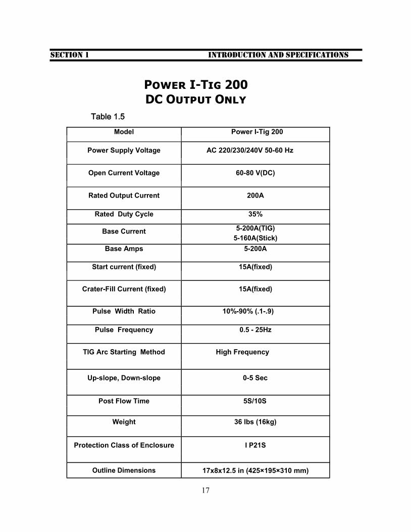
Model Power I-Tig 200
Power Supply Voltage AC 220/230/240V 50-60 Hz
Open Current Voltage 60-80 V(DC)
Rated Output Current 200A
Rated Duty Cycle 35%
Base Current 5-200A(TIG)
5-160A(Stick)
Base Amps 5-200A
Start current (fixed) 15A(fixed)
Crater-Fill Current (fixed) 15A(fixed)
Pulse Width Ratio 10%-90% (.1-.9)
Pulse Frequency 0.5 - 25Hz
TIG Arc Starting Method High Frequency
Up-slope, Down-slope 0-5 Sec
Post Flow Time 5S/10S
Weight 36 lbs (16kg)
Protection Class of Enclosure I P21S
Outline Dimensions 17x8x12.5 in (425×195×310 mm)
Introduction and Specifications Section 1
Power I-Tig 200 DC Output Only
Table 1.5
18
Introduction and Specifications Section 1
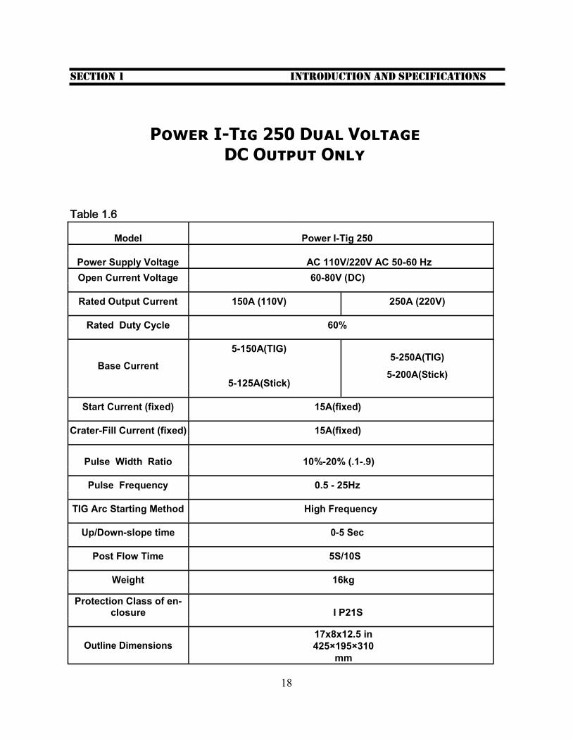
Model Power I-Tig 250
Power Supply Voltage AC 110V/220V AC 50-60 Hz
Open Current Voltage 60-80V (DC)
Rated Output Current 150A (110V) 250A (220V)
Rated Duty Cycle 60%
Base Current
5-150A(TIG) 5-250A(TIG)
5-125A(Stick)
5-200A(Stick)
Start Current (fixed) 15A(fixed)
Crater-Fill Current (fixed) 15A(fixed)
Pulse Width Ratio 10%-20% (.1-.9)
Pulse Frequency 0.5 - 25Hz
TIG Arc Starting Method High Frequency
Up/Down-slope time 0-5 Sec
Post Flow Time 5S/10S
Weight 16kg
Protection Class of en-closure I P21S
Outline Dimensions
17x8x12.5 in
425×195×310
mm
Power I-Tig 250 Dual Voltage DC Output Only
Table 1.6
19
Section 2 Know Your machine
PowerTig
1
2
3
4 5 6 7
8
9 10 11 12 13 14 15
16 17 18 19 20 21 22
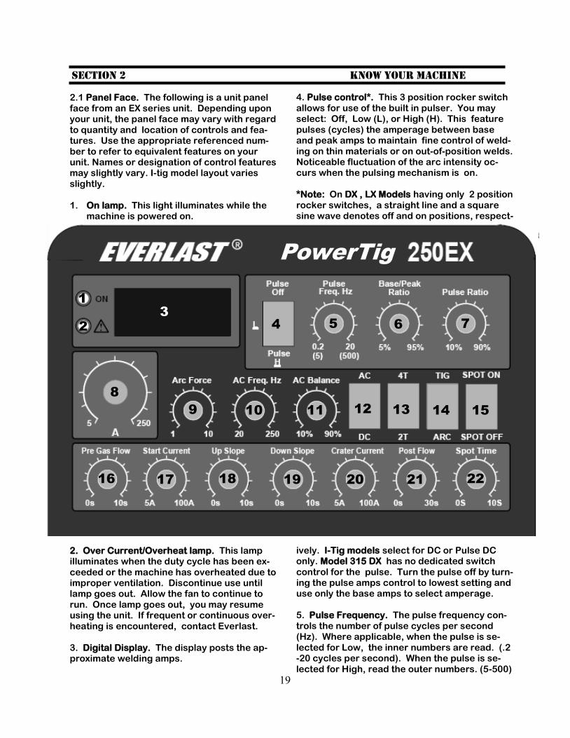
2.1 Panel Face. The following is a unit panel face from an EX series unit. Depending upon your unit, the panel face may vary with regard to quantity and location of controls and fea-tures. Use the appropriate referenced num-ber to refer to equivalent features on your unit. Names or designation of control features may slightly vary. I-tig model layout varies slightly. 1. On lamp. This light illuminates while the
machine is powered on. 2. Over Current/Overheat lamp. This lamp illuminates when the duty cycle has been ex-ceeded or the machine has overheated due to improper ventilation. Discontinue use until lamp goes out. Allow the fan to continue to run. Once lamp goes out, you may resume using the unit. If frequent or continuous over-heating is encountered, contact Everlast. 3. Digital Display. The display posts the ap-proximate welding amps.
4. Pulse control*. This 3 position rocker switch allows for use of the built in pulser. You may select: Off, Low (L), or High (H). This feature pulses (cycles) the amperage between base and peak amps to maintain fine control of weld-ing on thin materials or on out-of-position welds. Noticeable fluctuation of the arc intensity oc-curs when the pulsing mechanism is on. *Note: On DX , LX Models having only 2 position rocker switches, a straight line and a square sine wave denotes off and on positions, respect- ively. I-Tig models select for DC or Pulse DC only. Model 315 DX has no dedicated switch control for the pulse. Turn the pulse off by turn-ing the pulse amps control to lowest setting and use only the base amps to select amperage. 5. Pulse Frequency. The pulse frequency con-trols the number of pulse cycles per second (Hz). Where applicable, when the pulse is se-lected for Low, the inner numbers are read. (.2-20 cycles per second). When the pulse is se-lected for High, read the outer numbers. (5-500)
20
6. Base/Peak Ratio. This proportions the base amperage with the peak amperage of the pulse cycle, expressed as a percentage or decimal fraction of the peak amperage. Example: If the peak amperage is set for 100 amps, and the base/peak control knob is set for 95% (.9), then the low (base) am-perage cycle of the pulse will be approxi-mately 95 (90) amps. Regardless of no-menclature, the basic function of the con-trol is the same. The Model 315 DX ratio is adjusted by using the independent Base Amp and Peak Amp controls. Adjust the peak amps above the base amps for proper control of the pulse cycle. 7. Pulse Ratio. Some models: Pulse Width. This allows the relative amount of time that the pulse spends in the base (low) current stage during a defined cycle to be ad-justed. For example: A control knob set-ting of 90% or .9 will signal the pulser to spend 90% as long in the base (low) cur-rent stage as spends in the peak (high) cur-rent stage of the pulse cycle. Note: The Pulse Ratio does not control the overall length of the pulse. The pulse fre-quency setting sets the cycle length, thereby determining the overall length of each leg of the cycle. Within each cycle length, there is a certain amount (ratio) of time that the pulse spends in the base (low) amperage stage of the cycle and in the peak (high) amperage stage of the cycle. As the cycle frequency (Hz) increases, overall cycle length is shortened, thereby compressing the exact amount of time that the cycle spends in each stage. However, the pulse ratio continues to function within the compressed cycle proportionately. 8. Main Amperage Control. Some models: Welding Amps or Welding Current (DX/LX). Locations may vary. This control knob al-lows for precise control over the welding current. This control knob also is used in conjunction with the pulser to select the peak amps. 9. Arc Force. This controls the dig of the arc. The dig is a term used to describe the intensity of the arc. It determines how hard
Section 2 Know Your machine
continued
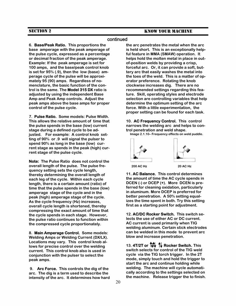
the arc penetrates the metal when the arc is held short. This is an exceptionally help-ful feature in MMA (SMAW) operation. It helps hold the molten metal in place in out-of-position welds by providing a crisp, forceful arc. Or, it can provide a soft, but-tery arc that easily washes the metal into the toes of the weld. This is a matter of op-erator preference. Rotating the knob clockwise increases dig. There are no recommended settings regarding this fea-ture. Skill, operating styles and electrode selection are controlling variables that help determine the optimum setting of the arc force. With a little experimentation, the proper setting can be found for each task. 10. AC Frequency Control. This control narrows the welding arc and helps to con-trol penetration and weld shape. Image 2.1.10– Frequency effects on weld puddle.
200 AC Hz 20 AC Hz
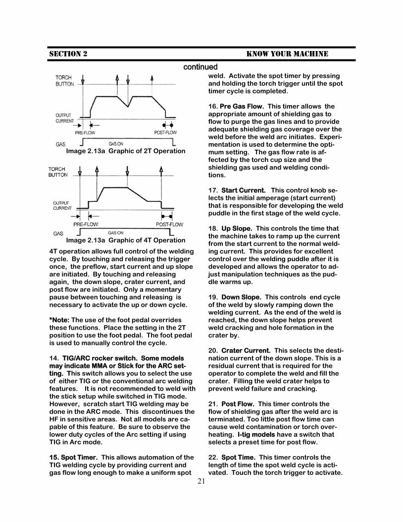
11. AC Balance. This control determines the amount of time the AC cycle spends in DCEN (-) or DCEP (+). More DCEN is pre-ferred for cleaning oxidation, particularly in aluminum. More DCEP is preferred for better penetration. A 50% setting equal-izes the time spent in both. Try this setting first as a starting point for adjustment. 12. AC/DC Rocker Switch. This switch se-lects the use of either AC or DC current. AC current is used primarily when TIG welding aluminum. Certain stick electrodes can be welded in this mode to prevent arc blow and increase penetration. 13. 4T/2T or Rocker Switch. This switch selects for control of the TIG weld cycle via the TIG torch trigger. In the 2T mode, simply touch and hold the trigger to start the arc and continue holding while welding. The machine will cycle automati-cally according to the settings selected on the machine. Release trigger the to finish.
21
Section 2 Know Your machine
continued
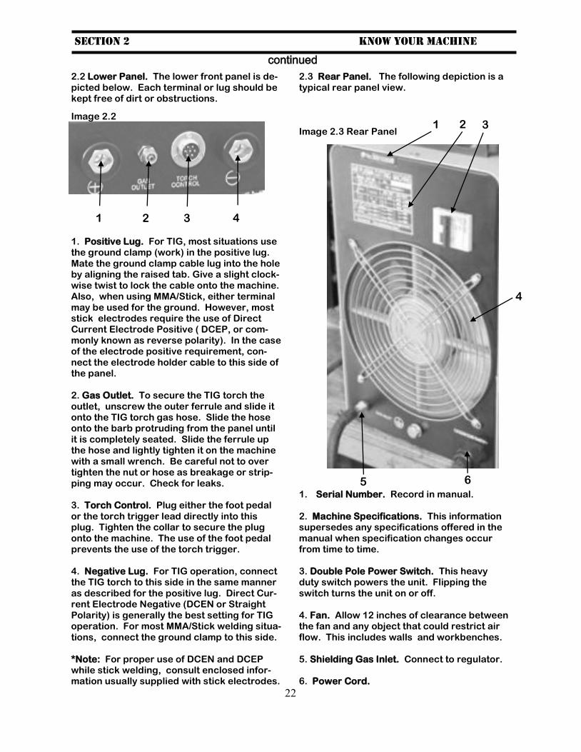
4T operation allows full control of the welding cycle. By touching and releasing the trigger once, the preflow, start current and up slope are initiated. By touching and releasing again, the down slope, crater current, and post flow are initiated. Only a momentary pause between touching and releasing is necessary to activate the up or down cycle. *Note: The use of the foot pedal overrides these functions. Place the setting in the 2T position to use the foot pedal. The foot pedal is used to manually control the cycle. 14. TIG/ARC rocker switch. Some models may indicate MMA or Stick for the ARC set-ting. This switch allows you to select the use of either TIG or the conventional arc welding features. It is not recommended to weld with the stick setup while switched in TIG mode. However, scratch start TIG welding may be done in the ARC mode. This discontinues the HF in sensitive areas. Not all models are ca-pable of this feature. Be sure to observe the lower duty cycles of the Arc setting if using TIG in Arc mode. 15. Spot Timer. This allows automation of the TIG welding cycle by providing current and gas flow long enough to make a uniform spot
weld. Activate the spot timer by pressing and holding the torch trigger until the spot timer cycle is completed. 16. Pre Gas Flow. This timer allows the appropriate amount of shielding gas to flow to purge the gas lines and to provide adequate shielding gas coverage over the weld before the weld arc initiates. Experi-mentation is used to determine the opti-mum setting. The gas flow rate is af-fected by the torch cup size and the shielding gas used and welding condi-tions. 17. Start Current. This control knob se-lects the initial amperage (start current) that is responsible for developing the weld puddle in the first stage of the weld cycle. 18. Up Slope. This controls the time that the machine takes to ramp up the current from the start current to the normal weld-ing current. This provides for excellent control over the welding puddle after it is developed and allows the operator to ad-just manipulation techniques as the pud-dle warms up. 19. Down Slope. This controls end cycle of the weld by slowly ramping down the welding current. As the end of the weld is reached, the down slope helps prevent weld cracking and hole formation in the crater by. 20. Crater Current. This selects the desti-nation current of the down slope. This is a residual current that is required for the operator to complete the weld and fill the crater. Filling the weld crater helps to prevent weld failure and cracking. 21. Post Flow. This timer controls the flow of shielding gas after the weld arc is terminated. Too little post flow time can cause weld contamination or torch over-heating. I-tig models have a switch that selects a preset time for post flow. 22. Spot Time. This timer controls the length of time the spot weld cycle is acti-vated. Touch the torch trigger to activate.
Image 2.13a Graphic of 2T Operation
Image 2.13a Graphic of 4T Operation
22
Section 2 Know Your machine
continued
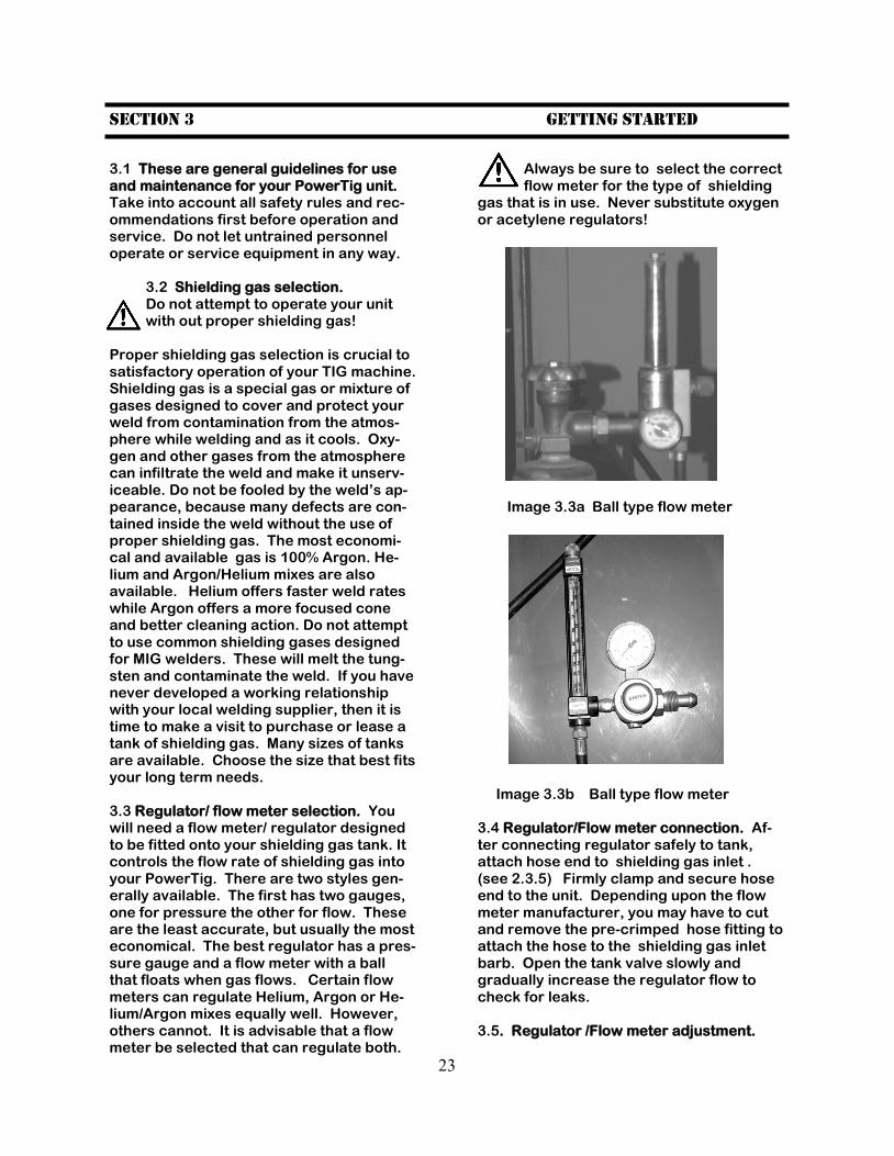
2.2 Lower Panel. The lower front panel is de-picted below. Each terminal or lug should be kept free of dirt or obstructions.
1. Positive Lug. For TIG, most situations use the ground clamp (work) in the positive lug. Mate the ground clamp cable lug into the hole by aligning the raised tab. Give a slight clock-wise twist to lock the cable onto the machine. Also, when using MMA/Stick, either terminal may be used for the ground. However, most stick electrodes require the use of Direct Current Electrode Positive ( DCEP, or com-monly known as reverse polarity). In the case of the electrode positive requirement, con-nect the electrode holder cable to this side of the panel. 2. Gas Outlet. To secure the TIG torch the outlet, unscrew the outer ferrule and slide it onto the TIG torch gas hose. Slide the hose onto the barb protruding from the panel until it is completely seated. Slide the ferrule up the hose and lightly tighten it on the machine with a small wrench. Be careful not to over tighten the nut or hose as breakage or strip-ping may occur. Check for leaks. 3. Torch Control. Plug either the foot pedal or the torch trigger lead directly into this plug. Tighten the collar to secure the plug onto the machine. The use of the foot pedal prevents the use of the torch trigger. 4. Negative Lug. For TIG operation, connect the TIG torch to this side in the same manner as described for the positive lug. Direct Cur-rent Electrode Negative (DCEN or Straight Polarity) is generally the best setting for TIG operation. For most MMA/Stick welding situa-tions, connect the ground clamp to this side. *Note: For proper use of DCEN and DCEP while stick welding, consult enclosed infor-mation usually supplied with stick electrodes.
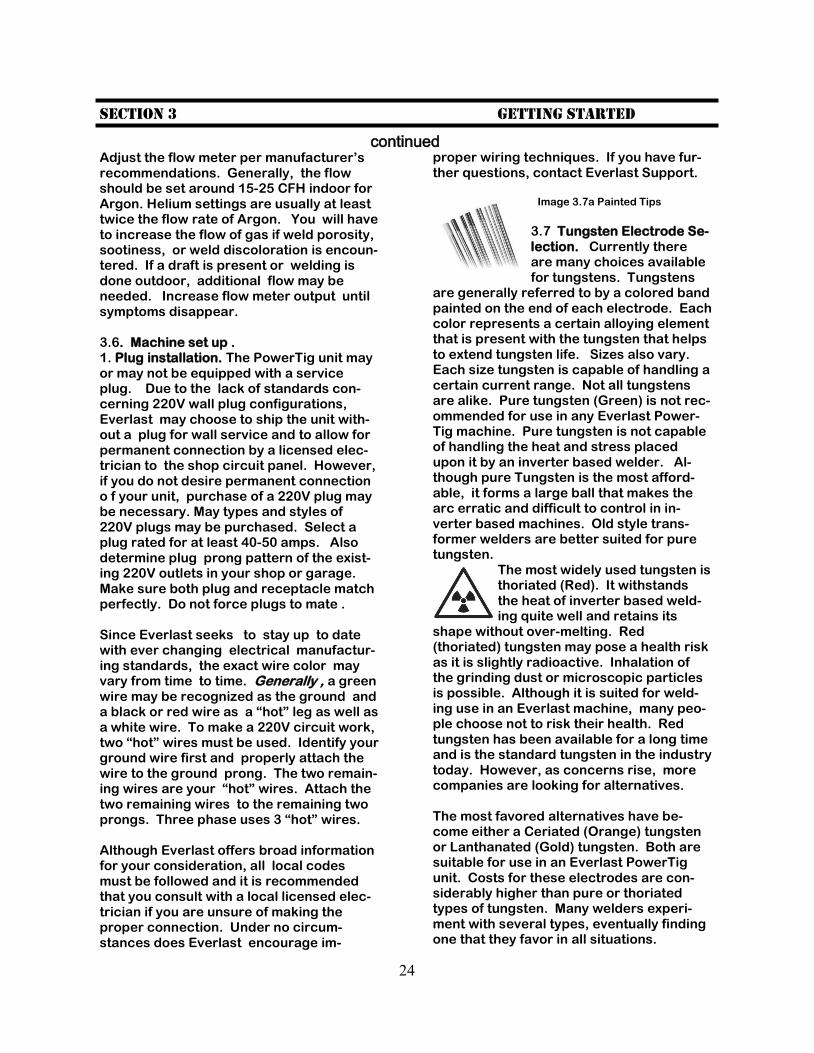
2.3 Rear Panel. The following depiction is a typical rear panel view. Image 2.3 Rear Panel 1. Serial Number. Record in manual. 2. Machine Specifications. This information supersedes any specifications offered in the manual when specification changes occur from time to time. 3. Double Pole Power Switch. This heavy duty switch powers the unit. Flipping the switch turns the unit on or off. 4. Fan. Allow 12 inches of clearance between the fan and any object that could restrict air flow. This includes walls and workbenches. 5. Shielding Gas Inlet. Connect to regulator. 6. Power Cord.
1 2 3 4
1 2 3
4
5 6
Image 2.2
23
Section 3 Getting started
3.1 These are general guidelines for use and maintenance for your PowerTig unit. Take into account all safety rules and rec-ommendations first before operation and service. Do not let untrained personnel operate or service equipment in any way.
3.2 Shielding gas selection. Do not attempt to operate your unit with out proper shielding gas!
Proper shielding gas selection is crucial to satisfactory operation of your TIG machine. Shielding gas is a special gas or mixture of gases designed to cover and protect your weld from contamination from the atmos-phere while welding and as it cools. Oxy-gen and other gases from the atmosphere can infiltrate the weld and make it unserv-iceable. Do not be fooled by the weld’s ap-pearance, because many defects are con-tained inside the weld without the use of proper shielding gas. The most economi-cal and available gas is 100% Argon. He-lium and Argon/Helium mixes are also available. Helium offers faster weld rates while Argon offers a more focused cone and better cleaning action. Do not attempt to use common shielding gases designed for MIG welders. These will melt the tung-sten and contaminate the weld. If you have never developed a working relationship with your local welding supplier, then it is time to make a visit to purchase or lease a tank of shielding gas. Many sizes of tanks are available. Choose the size that best fits your long term needs. 3.3 Regulator/ flow meter selection. You will need a flow meter/ regulator designed to be fitted onto your shielding gas tank. It controls the flow rate of shielding gas into your PowerTig. There are two styles gen-erally available. The first has two gauges, one for pressure the other for flow. These are the least accurate, but usually the most economical. The best regulator has a pres-sure gauge and a flow meter with a ball that floats when gas flows. Certain flow meters can regulate Helium, Argon or He-lium/Argon mixes equally well. However, others cannot. It is advisable that a flow meter be selected that can regulate both.
Always be sure to select the correct flow meter for the type of shielding
gas that is in use. Never substitute oxygen or acetylene regulators! Image 3.3a Ball type flow meter Image 3.3b Ball type flow meter 3.4 Regulator/Flow meter connection. Af-ter connecting regulator safely to tank, attach hose end to shielding gas inlet . (see 2.3.5) Firmly clamp and secure hose end to the unit. Depending upon the flow meter manufacturer, you may have to cut and remove the pre-crimped hose fitting to attach the hose to the shielding gas inlet barb. Open the tank valve slowly and gradually increase the regulator flow to check for leaks. 3.5. Regulator /Flow meter adjustment.
24
Section 3 Getting started
continued Adjust the flow meter per manufacturer’s recommendations. Generally, the flow should be set around 15-25 CFH indoor for Argon. Helium settings are usually at least twice the flow rate of Argon. You will have to increase the flow of gas if weld porosity, sootiness, or weld discoloration is encoun-tered. If a draft is present or welding is done outdoor, additional flow may be needed. Increase flow meter output until symptoms disappear. 3.6. Machine set up . 1. Plug installation. The PowerTig unit may or may not be equipped with a service plug. Due to the lack of standards con-cerning 220V wall plug configurations, Everlast may choose to ship the unit with-out a plug for wall service and to allow for permanent connection by a licensed elec-trician to the shop circuit panel. However, if you do not desire permanent connection o f your unit, purchase of a 220V plug may be necessary. May types and styles of 220V plugs may be purchased. Select a plug rated for at least 40-50 amps. Also determine plug prong pattern of the exist-ing 220V outlets in your shop or garage. Make sure both plug and receptacle match perfectly. Do not force plugs to mate . Since Everlast seeks to stay up to date with ever changing electrical manufactur-ing standards, the exact wire color may vary from time to time. Generally , a green wire may be recognized as the ground and a black or red wire as a “hot” leg as well as a white wire. To make a 220V circuit work, two “hot” wires must be used. Identify your ground wire first and properly attach the wire to the ground prong. The two remain-ing wires are your “hot” wires. Attach the two remaining wires to the remaining two prongs. Three phase uses 3 “hot” wires. Although Everlast offers broad information for your consideration, all local codes must be followed and it is recommended that you consult with a local licensed elec-trician if you are unsure of making the proper connection. Under no circum-stances does Everlast encourage im-
proper wiring techniques. If you have fur-ther questions, contact Everlast Support.
Image 3.7a Painted Tips
3.7 Tungsten Electrode Se-lection. Currently there are many choices available for tungstens. Tungstens
are generally referred to by a colored band painted on the end of each electrode. Each color represents a certain alloying element that is present with the tungsten that helps to extend tungsten life. Sizes also vary. Each size tungsten is capable of handling a certain current range. Not all tungstens are alike. Pure tungsten (Green) is not rec-ommended for use in any Everlast Power-Tig machine. Pure tungsten is not capable of handling the heat and stress placed upon it by an inverter based welder. Al-though pure Tungsten is the most afford-able, it forms a large ball that makes the arc erratic and difficult to control in in-verter based machines. Old style trans-former welders are better suited for pure tungsten.
The most widely used tungsten is thoriated (Red). It withstands the heat of inverter based weld-ing quite well and retains its
shape without over-melting. Red (thoriated) tungsten may pose a health risk as it is slightly radioactive. Inhalation of the grinding dust or microscopic particles is possible. Although it is suited for weld-ing use in an Everlast machine, many peo-ple choose not to risk their health. Red tungsten has been available for a long time and is the standard tungsten in the industry today. However, as concerns rise, more companies are looking for alternatives. The most favored alternatives have be-come either a Ceriated (Orange) tungsten or Lanthanated (Gold) tungsten. Both are suitable for use in an Everlast PowerTig unit. Costs for these electrodes are con-siderably higher than pure or thoriated types of tungsten. Many welders experi-ment with several types, eventually finding one that they favor in all situations.
25
Section 3 Getting started
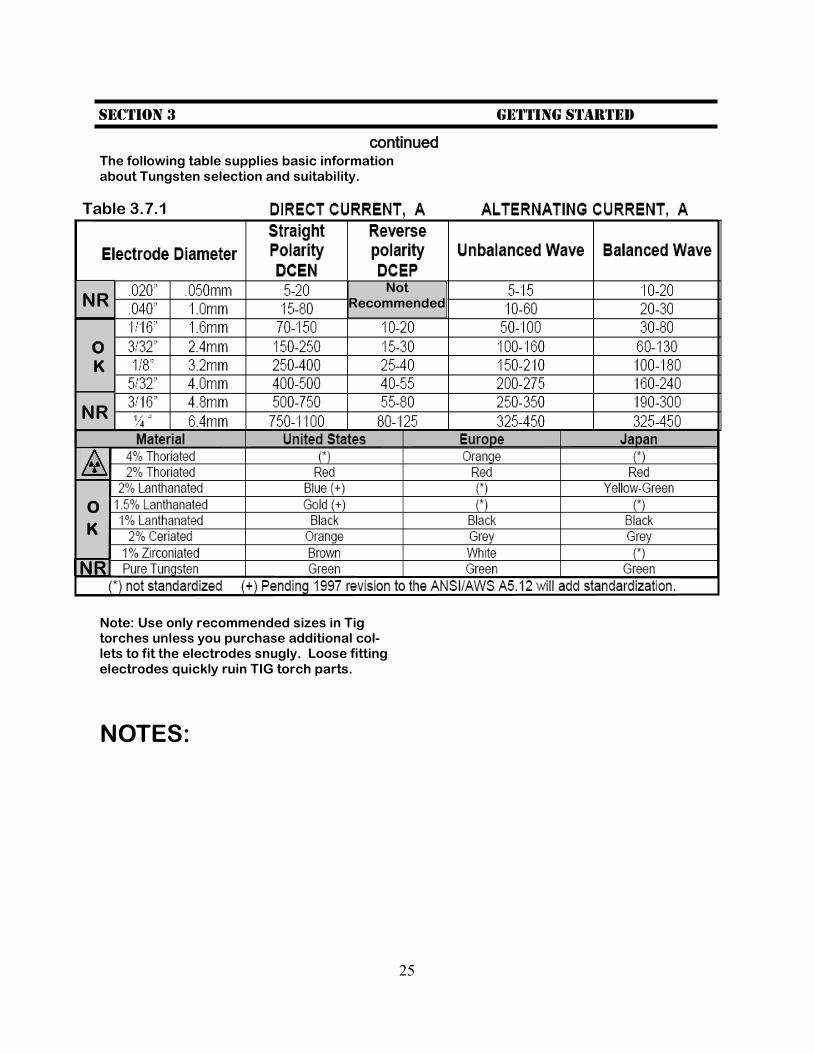
continued The following table supplies basic information about Tungsten selection and suitability.
Note: Use only recommended sizes in Tig torches unless you purchase additional col-lets to fit the electrodes snugly. Loose fitting electrodes quickly ruin TIG torch parts.
NOTES:
NR
NR
O
K
O
K
NR
Table 3.7.1
Not Recommended
26
Section 3 Getting started
continued 3.8 TIG Torch. Becoming fa-miliar with a TIG torch is a necessary step to becoming proficient at TIG welding. Due to constant issues with sharp-ening and replacement of the tungsten, frequent adjust-ment and breakdown of the torch components is often re-quired. Refer to the following image for a typical TIG torch breakdown.
Image 3.8b Typical Torch Parts
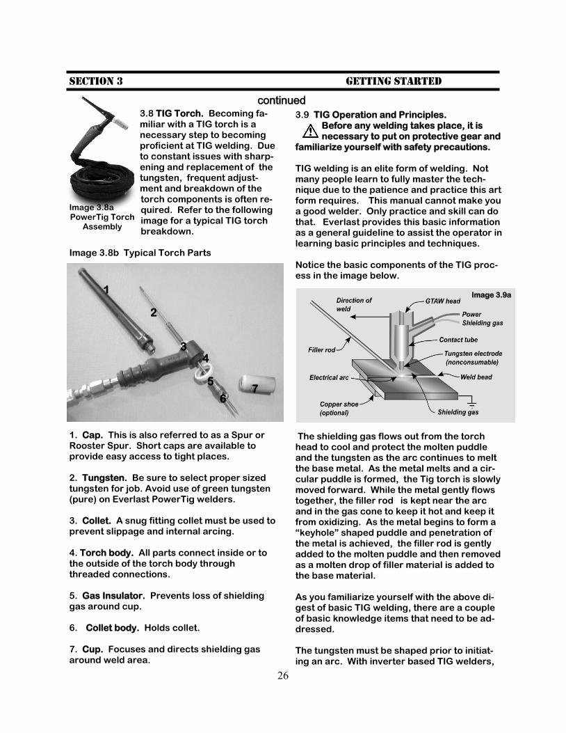
1. Cap. This is also referred to as a Spur or Rooster Spur. Short caps are available to provide easy access to tight places. 2. Tungsten. Be sure to select proper sized tungsten for job. Avoid use of green tungsten (pure) on Everlast PowerTig welders. 3. Collet. A snug fitting collet must be used to prevent slippage and internal arcing. 4. Torch body. All parts connect inside or to the outside of the torch body through threaded connections. 5. Gas Insulator. Prevents loss of shielding gas around cup. 6. Collet body. Holds collet. 7. Cup. Focuses and directs shielding gas around weld area.
3.9 TIG Operation and Principles. Before any welding takes place, it is necessary to put on protective gear and
familiarize yourself with safety precautions. TIG welding is an elite form of welding. Not many people learn to fully master the tech-nique due to the patience and practice this art form requires. This manual cannot make you a good welder. Only practice and skill can do that. Everlast provides this basic information as a general guideline to assist the operator in learning basic principles and techniques. Notice the basic components of the TIG proc-ess in the image below.
The shielding gas flows out from the torch head to cool and protect the molten puddle and the tungsten as the arc continues to melt the base metal. As the metal melts and a cir-cular puddle is formed, the Tig torch is slowly moved forward. While the metal gently flows together, the filler rod is kept near the arc and in the gas cone to keep it hot and keep it from oxidizing. As the metal begins to form a “keyhole” shaped puddle and penetration of the metal is achieved, the filler rod is gently added to the molten puddle and then removed as a molten drop of filler material is added to the base material. As you familiarize yourself with the above di-gest of basic TIG welding, there are a couple of basic knowledge items that need to be ad-dressed. The tungsten must be shaped prior to initiat-ing an arc. With inverter based TIG welders,
Image 3.8a PowerTig Torch
Assembly
1
2
4
5
6 7
3
Image 3.9a
27
Section 3 Getting started
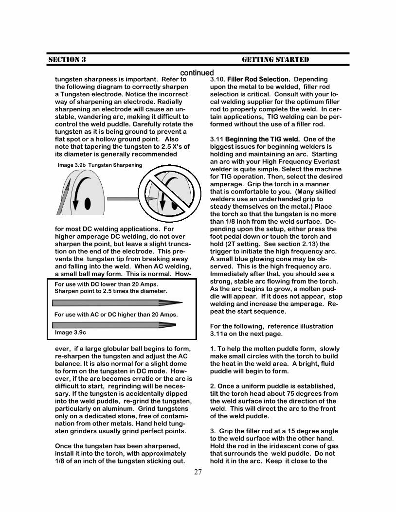
continued tungsten sharpness is important. Refer to the following diagram to correctly sharpen a Tungsten electrode. Notice the incorrect way of sharpening an electrode. Radially sharpening an electrode will cause an un-stable, wandering arc, making it difficult to control the weld puddle. Carefully rotate the tungsten as it is being ground to prevent a flat spot or a hollow ground point. Also note that tapering the tungsten to 2.5 X’s of its diameter is generally recommended
for most DC welding applications. For higher amperage DC welding, do not over sharpen the point, but leave a slight trunca-tion on the end of the electrode. This pre-vents the tungsten tip from breaking away and falling into the weld. When AC welding, a small ball may form. This is normal. How-
ever, if a large globular ball begins to form, re-sharpen the tungsten and adjust the AC balance. It is also normal for a slight dome to form on the tungsten in DC mode. How-ever, if the arc becomes erratic or the arc is difficult to start, regrinding will be neces-sary. If the tungsten is accidentally dipped into the weld puddle, re-grind the tungsten, particularly on aluminum. Grind tungstens only on a dedicated stone, free of contami-nation from other metals. Hand held tung-sten grinders usually grind perfect points. Once the tungsten has been sharpened, install it into the torch, with approximately 1/8 of an inch of the tungsten sticking out.
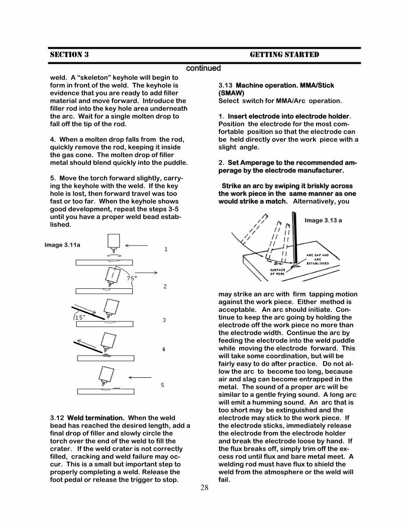
3.10. Filler Rod Selection. Depending upon the metal to be welded, filler rod selection is critical. Consult with your lo-cal welding supplier for the optimum filler rod to properly complete the weld. In cer-tain applications, TIG welding can be per-formed without the use of a filler rod. 3.11 Beginning the TIG weld. One of the biggest issues for beginning welders is holding and maintaining an arc. Starting an arc with your High Frequency Everlast welder is quite simple. Select the machine for TIG operation. Then, select the desired amperage. Grip the torch in a manner that is comfortable to you. (Many skilled welders use an underhanded grip to steady themselves on the metal.) Place the torch so that the tungsten is no more than 1/8 inch from the weld surface. De-pending upon the setup, either press the foot pedal down or touch the torch and hold (2T setting. See section 2.13) the trigger to initiate the high frequency arc. A small blue glowing cone may be ob-served. This is the high frequency arc. Immediately after that, you should see a strong, stable arc flowing from the torch. As the arc begins to grow, a molten pud-dle will appear. If it does not appear, stop welding and increase the amperage. Re-peat the start sequence. For the following, reference illustration 3.11a on the next page. 1. To help the molten puddle form, slowly make small circles with the torch to build the heat in the weld area. A bright, fluid puddle will begin to form. 2. Once a uniform puddle is established, tilt the torch head about 75 degrees from the weld surface into the direction of the weld. This will direct the arc to the front of the weld puddle. 3. Grip the filler rod at a 15 degree angle to the weld surface with the other hand. Hold the rod in the iridescent cone of gas that surrounds the weld puddle. Do not hold it in the arc. Keep it close to the
Image 3.9b Tungsten Sharpening
For use with DC lower than 20 Amps. Sharpen point to 2.5 times the diameter.
For use with AC or DC higher than 20 Amps.
Image 3.9c
28
Section 3 Getting started
continued weld. A “skeleton” keyhole will begin to form in front of the weld. The keyhole is evidence that you are ready to add filler material and move forward. Introduce the filler rod into the key hole area underneath the arc. Wait for a single molten drop to fall off the tip of the rod. 4. When a molten drop falls from the rod, quickly remove the rod, keeping it inside the gas cone. The molten drop of filler metal should blend quickly into the puddle. 5. Move the torch forward slightly, carry-ing the keyhole with the weld. If the key hole is lost, then forward travel was too fast or too far. When the keyhole shows good development, repeat the steps 3-5 until you have a proper weld bead estab-lished.
3.12 Weld termination. When the weld bead has reached the desired length, add a final drop of filler and slowly circle the torch over the end of the weld to fill the crater. If the weld crater is not correctly filled, cracking and weld failure may oc-cur. This is a small but important step to properly completing a weld. Release the foot pedal or release the trigger to stop.
3.13 Machine operation. MMA/Stick(SMAW) Select switch for MMA/Arc operation. 1. Insert electrode into electrode holder. Position the electrode for the most com-fortable position so that the electrode can be held directly over the work piece with a slight angle. 2. Set Amperage to the recommended am-perage by the electrode manufacturer. Strike an arc by swiping it briskly across the work piece in the same manner as one would strike a match. Alternatively, you may strike an arc with firm tapping motion against the work piece. Either method is acceptable. An arc should initiate. Con-tinue to keep the arc going by holding the electrode off the work piece no more than the electrode width. Continue the arc by feeding the electrode into the weld puddle while moving the electrode forward. This will take some coordination, but will be fairly easy to do after practice. Do not al-low the arc to become too long, because air and slag can become entrapped in the metal. The sound of a proper arc will be similar to a gentle frying sound. A long arc will emit a humming sound. An arc that is too short may be extinguished and the electrode may stick to the work piece. If the electrode sticks, immediately release the electrode from the electrode holder and break the electrode loose by hand. If the flux breaks off, simply trim off the ex-cess rod until flux and bare metal meet. A welding rod must have flux to shield the weld from the atmosphere or the weld will fail.
Image 3.11a
Image 3.13 a
29
Section 3 Getting started
continued 4. Use the Arc force and Amp adjustment to change arc qualities. Adjust the amper-age according to the recommendations of the electrode (welding rod) manufacturer for the type and size of the electrode used. The arc force will affect how crisp the arc is whether it is smooth and buttery or deeply penetrating. Use it to suit the de-sired weld finish. Experimentation will be required to find the optimal setting de-sired. It is an excellent tool for out of posi-tion welding. 5. Electrode selection. Electrodes are usually given performance and character-istic ratings using a system of letters and numbers determined by the American Welding Society (AWS). The rating system includes the minimum tensile strength of the finished weld, the weld position (flat, vertical, horizontal, or overhead or a com-bination of two or more positions) and the flux type. Additional information may be given. Each manufacturer has their indi-vidual name and terminology as well. As there is no general recommendation that can be made about a particular electrode selection, except for practice welds, a electrode designated by the AWS as E 6011, E 6013, E 7014, or E 7018 may be used, each having its own distinct features and purpose. These are among the most common electrodes used in the industry and are not difficult to find. E 6011 elec-trodes are not as smooth running as some of the other electrodes, but offer the ad-vantage of being able to weld on rusty metal and contaminated surfaces. It is widely used and requires very little skill to begin using. This is not a particular en-dorsement of an E6011, rather a simple example of what may be used in develop-ing proficient technique. It is recom-mended that a variety of electrodes be used and practiced with. Consultation with an experienced local welding supplier will help greatly in determining what weld-ing electrode is the best for your given situation. Many times, samples or small packages of electrodes are available at relatively low cost to determine for your-self the best electrode to use.
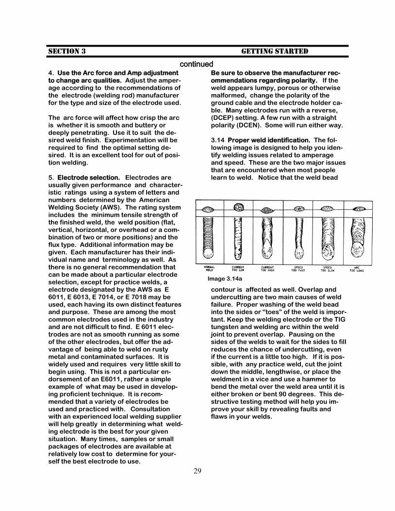
Be sure to observe the manufacturer rec-ommendations regarding polarity. If the weld appears lumpy, porous or otherwise malformed, change the polarity of the ground cable and the electrode holder ca-ble. Many electrodes run with a reverse, (DCEP) setting. A few run with a straight polarity (DCEN). Some will run either way. 3.14 Proper weld identification. The fol-lowing image is designed to help you iden-tify welding issues related to amperage and speed. These are the two major issues that are encountered when most people learn to weld. Notice that the weld bead
contour is affected as well. Overlap and undercutting are two main causes of weld failure. Proper washing of the weld bead into the sides or “toes” of the weld is impor-tant. Keep the welding electrode or the TIG tungsten and welding arc within the weld joint to prevent overlap. Pausing on the sides of the welds to wait for the sides to fill reduces the chance of undercutting, even if the current is a little too high. If it is pos-sible, with any practice weld, cut the joint down the middle, lengthwise, or place the weldment in a vice and use a hammer to bend the metal over the weld area until it is either broken or bent 90 degrees. This de-structive testing method will help you im-prove your skill by revealing faults and flaws in your welds.
Image 3.14a
30
Section 4 Trouble Shooting
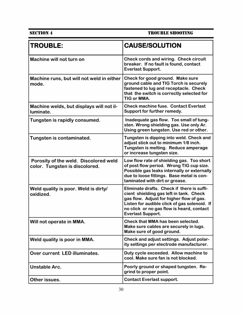
TROUBLE: CAUSE/SOLUTION
Machine will not turn on Check cords and wiring. Check circuit breaker. If no fault is found, contact Everlast Support.
Machine runs, but will not weld in either mode.
Check for good ground. Make sure ground cable and TIG Torch is securely fastened to lug and receptacle. Check that the switch is correctly selected for TIG or MMA.
Machine welds, but displays will not il-luminate.
Check machine fuse. Contact Everlast Support for further remedy.
Tungsten is rapidly consumed. Inadequate gas flow. Too small of tung-sten. Wrong shielding gas. Use only Ar. Using green tungsten. Use red or other.
Tungsten is contaminated. Tungsten is dipping into weld. Check and adjust stick out to minimum 1/8 inch. Tungsten is melting. Reduce amperage or increase tungsten size.
Porosity of the weld. Discolored weld color. Tungsten is discolored.
Low flow rate of shielding gas. Too short of post flow period. Wrong TIG cup size. Possible gas leaks internally or externally due to loose fittings. Base metal is con-taminated with dirt or grease.
Weld quality is poor. Weld is dirty/oxidized.
Eliminate drafts. Check if there is suffi-cient shielding gas left in tank. Check gas flow. Adjust for higher flow of gas. Listen for audible click of gas solenoid. If no click or no gas flow is heard, contact Everlast Support.
Will not operate in MMA. Check that MMA has been selected. Make sure cables are securely in lugs. Make sure of good ground.
Weld quality is poor in MMA. Check and adjust settings. Adjust polar-ity settings per electrode manufacturer.
Over current LED illuminates. Duty cycle exceeded. Allow machine to cool. Make sure fan is not blocked.
Unstable Arc. Poorly ground or shaped tungsten. Re-grind to proper point.
Other issues. Contact Everlast support.

31