evergreen - acare · constraints allow the use of the carrier evergreen centrifugal ... table of...
TRANSCRIPT

High-Efficiency Hermetic Centrifugal Liquid Chillers
19XRNominal cooling capacity 1000-5300 kW
Carrier’s Evergreen centrifugal chillers provide exceptionalvalue by achieving energy efficiency levels as high as 6.8(COP) utilizing proven technology designed specifically forchlorine-free refrigerant:
■ Unique concept of the hermetic compressor:- Single-stage aerodynamic impeller- Tunnel diffusers, based on aircraft engine technology- Motor cooled by refrigerant gas injection
■ Use of high-efficiency evaporator and condenser tubes■ Expansion sub-cooler integrated into the condenser■ Patented float valve technology for optimised sub-cooling
and refrigerant level in the evaporator
These advantages, together with the modularity of the unitsand their efficiency, economical operation and dimensionalconstraints allow the use of the Carrier Evergreen centrifugalchillers in any high-capacity water cooling applications.
Features■ Environmentally-preferred HFC-134a refrigerant
The Evergreen chillers use chlorine-free HFC-134arefrigerant with zero ozone-depletion potential, therefrigerant of choice for automotive and appliancemanufacturers.
■ Mix-match capabilitiesThe chillers provide a complete line of compressors and heatexchangers, ensuring the optimal combination of machinecomponents regardless of capacity, lift, and efficiencyspecifications.
■ Heat exchangers feature: European pressure vessel code certified construction,ensuring maximum heat exchanger safety, reliability andlong life.
■ Single-stage hermetic compressorThis design:- increases product reliability by eliminating the additional
moving parts associated with multiple stage machines, suchas additional guide vanes and complex economizers.
- eliminates refrigerant leaks from the compressor/motortransmission joints in open-drive compressors
■ Aerodynamically-contoured impellersImpellers that utilize high back sweep main blades with low-profile intermediate splitter blades are aerodynamicallycontoured to improve compressor full-load and part-loadoperating efficiency.
Evergreen™C H I L L E R S
2
Table of contentsFeatures . . . . . . . . . . . . . . . . . . . . . . . . . . . . . . . . . . . . . . . . . . . . . . . . . . . . . . . . . . . . . . . . . . . . . . . . . . . . . . . . . . . . . . . . . . . . . . . . . . 1Easy installation . . . . . . . . . . . . . . . . . . . . . . . . . . . . . . . . . . . . . . . . . . . . . . . . . . . . . . . . . . . . . . . . . . . . . . . . . . . . . . . . . . . . . . . . . . . 2Power supply and controls . . . . . . . . . . . . . . . . . . . . . . . . . . . . . . . . . . . . . . . . . . . . . . . . . . . . . . . . . . . . . . . . . . . . . . . . . . . . . . . . . . . 2Variable inlet guide vanes (capacity control) . . . . . . . . . . . . . . . . . . . . . . . . . . . . . . . . . . . . . . . . . . . . . . . . . . . . . . . . . . . . . . . . . . . . . 3Simple to service . . . . . . . . . . . . . . . . . . . . . . . . . . . . . . . . . . . . . . . . . . . . . . . . . . . . . . . . . . . . . . . . . . . . . . . . . . . . . . . . . . . . . . . . . . 3Model number nomenclature . . . . . . . . . . . . . . . . . . . . . . . . . . . . . . . . . . . . . . . . . . . . . . . . . . . . . . . . . . . . . . . . . . . . . . . . . . . . . . . . . 4Options and accessories . . . . . . . . . . . . . . . . . . . . . . . . . . . . . . . . . . . . . . . . . . . . . . . . . . . . . . . . . . . . . . . . . . . . . . . . . . . . . . . . . . . . . 4Starter features and options . . . . . . . . . . . . . . . . . . . . . . . . . . . . . . . . . . . . . . . . . . . . . . . . . . . . . . . . . . . . . . . . . . . . . . . . . . . . . . . . . . 5Physical data . . . . . . . . . . . . . . . . . . . . . . . . . . . . . . . . . . . . . . . . . . . . . . . . . . . . . . . . . . . . . . . . . . . . . . . . . . . . . . . . . . . . . . . . . . . . . 5Maximum outside temperatures . . . . . . . . . . . . . . . . . . . . . . . . . . . . . . . . . . . . . . . . . . . . . . . . . . . . . . . . . . . . . . . . . . . . . . . . . . . . . . . 5Unit operating range . . . . . . . . . . . . . . . . . . . . . . . . . . . . . . . . . . . . . . . . . . . . . . . . . . . . . . . . . . . . . . . . . . . . . . . . . . . . . . . . . . . . . . . . 5General electrical data . . . . . . . . . . . . . . . . . . . . . . . . . . . . . . . . . . . . . . . . . . . . . . . . . . . . . . . . . . . . . . . . . . . . . . . . . . . . . . . . . . . . . . 6Electrical characteristics of the motors. . . . . . . . . . . . . . . . . . . . . . . . . . . . . . . . . . . . . . . . . . . . . . . . . . . . . . . . . . . . . . . . . . . . . . . . . . 7Refrigeration cycle (centrifugal chiller) . . . . . . . . . . . . . . . . . . . . . . . . . . . . . . . . . . . . . . . . . . . . . . . . . . . . . . . . . . . . . . . . . . . . . . . . 9Compressor components . . . . . . . . . . . . . . . . . . . . . . . . . . . . . . . . . . . . . . . . . . . . . . . . . . . . . . . . . . . . . . . . . . . . . . . . . . . . . . . . . . . 10Machine components . . . . . . . . . . . . . . . . . . . . . . . . . . . . . . . . . . . . . . . . . . . . . . . . . . . . . . . . . . . . . . . . . . . . . . . . . . . . . . . . . . . . . . 11Machine dimensions . . . . . . . . . . . . . . . . . . . . . . . . . . . . . . . . . . . . . . . . . . . . . . . . . . . . . . . . . . . . . . . . . . . . . . . . . . . . . . . . . . . . . . 12Application data, mounting arrangement. . . . . . . . . . . . . . . . . . . . . . . . . . . . . . . . . . . . . . . . . . . . . . . . . . . . . . . . . . . . . . . . . . . . . . . 13Unit levelling . . . . . . . . . . . . . . . . . . . . . . . . . . . . . . . . . . . . . . . . . . . . . . . . . . . . . . . . . . . . . . . . . . . . . . . . . . . . . . . . . . . . . . . . . . . . 13Soleplate accessory detail . . . . . . . . . . . . . . . . . . . . . . . . . . . . . . . . . . . . . . . . . . . . . . . . . . . . . . . . . . . . . . . . . . . . . . . . . . . . . . . . . . . 13Waterboxes - nozzle arrangements. . . . . . . . . . . . . . . . . . . . . . . . . . . . . . . . . . . . . . . . . . . . . . . . . . . . . . . . . . . . . . . . . . . . . . . . . . . . 14A - Nozzle-in-head arrangement codes . . . . . . . . . . . . . . . . . . . . . . . . . . . . . . . . . . . . . . . . . . . . . . . . . . . . . . . . . . . . . . . . . . . . . . . . 14Sizes 4, 5 and 6 . . . . . . . . . . . . . . . . . . . . . . . . . . . . . . . . . . . . . . . . . . . . . . . . . . . . . . . . . . . . . . . . . . . . . . . . . . . . . . . . . . . . . . . . . . . 14Sizes 7 and 8 . . . . . . . . . . . . . . . . . . . . . . . . . . . . . . . . . . . . . . . . . . . . . . . . . . . . . . . . . . . . . . . . . . . . . . . . . . . . . . . . . . . . . . . . . . . . . 14B – Marine nozzle arrangement codes . . . . . . . . . . . . . . . . . . . . . . . . . . . . . . . . . . . . . . . . . . . . . . . . . . . . . . . . . . . . . . . . . . . . . . . . . 15Size 3. . . . . . . . . . . . . . . . . . . . . . . . . . . . . . . . . . . . . . . . . . . . . . . . . . . . . . . . . . . . . . . . . . . . . . . . . . . . . . . . . . . . . . . . . . . . . . . . . . . 15Sizes 4, 5 and 6 . . . . . . . . . . . . . . . . . . . . . . . . . . . . . . . . . . . . . . . . . . . . . . . . . . . . . . . . . . . . . . . . . . . . . . . . . . . . . . . . . . . . . . . . . . . 15Sizes 7 and 8 . . . . . . . . . . . . . . . . . . . . . . . . . . . . . . . . . . . . . . . . . . . . . . . . . . . . . . . . . . . . . . . . . . . . . . . . . . . . . . . . . . . . . . . . . . . . . 16Technical description . . . . . . . . . . . . . . . . . . . . . . . . . . . . . . . . . . . . . . . . . . . . . . . . . . . . . . . . . . . . . . . . . . . . . . . . . . . . . . . . . . . . . . 17Typical piping and wiring. . . . . . . . . . . . . . . . . . . . . . . . . . . . . . . . . . . . . . . . . . . . . . . . . . . . . . . . . . . . . . . . . . . . . . . . . . . . . . . . . . . 1819XR chiller with optional unit-mounted starter . . . . . . . . . . . . . . . . . . . . . . . . . . . . . . . . . . . . . . . . . . . . . . . . . . . . . . . . . . . . . . . . . 1819XR chiller with free-standing starter . . . . . . . . . . . . . . . . . . . . . . . . . . . . . . . . . . . . . . . . . . . . . . . . . . . . . . . . . . . . . . . . . . . . . . . . 19
Easy installation ■ Modular construction
The cooler, condenser, and compressor assemblies arecompletely bolted together, making the Evergreen chillersideally suited for replacement projects where ease ofdisassembly and reassembly at the jobsite are essential.
■ Water pipingThe unit has quick and easy piping: the standard unitincludes nozzle-in head water boxes with Victaulic groovesto allow for use of Victaulic couplings. Flanges are availableas an option.
■ Optional unit-mounted starterCarrier’s unit-mounted starter is available as a low-voltageversion and provides a single point power connection,reducing machine installation time and expense.
■ Quick start-up Quick start-up is assured once installation is complete, aseach 19XR unit is manufactured at an ISO 9001 listedmanufacturing facility to guarantee quality. All units arefactory-tested to allow easy and reliable start-up at job site.Compressors are run-tested to ensure proper operation of allcompressor systems, including oil management, vibration,electrical, power transmission, and compression.
Power supply and controls1-Electrical cabinets:
■ Serviceability and convenience have been “designed-in”, forexample:- Control transformer is fitted as standard- Single-point mains power connection if unit-mounted
starter is supplied- All components are mounted using connectors to facilitate
fast servicing and replacement- Components are labelled and numbered according to wiring
diagrams- IP 23C protection on the whole unit
2 - Microprocessor controls features:
■ Numerical product-integrated control (PIC II) The Carrier numerical control integrated into the second-generation products (PIC II Product Integrated Controls)provides unmatched flexibility and functionality. Each unitintegrates directly with the Carrier Comfort Network (CCN),providing a system solution to controls applications.
■ Human Interface (CVC)The CVC (Cooler Visual Control) interface, which can beconfigured to display units in Imperial or metric, providesunparalleled ease of operation. A 16-line by 40-characterLCD (Liquid Crystal Display) features 4 menu-specific softkeys. Default display offers easy, quick review of key chilleroperation data, simplifying the interaction between machineand user.Local languages are available upon request.
■ Chilled water reset Reset can be accomplished manually or automatically fromthe building management system. Reset saves energy whenwarmer chilled water can be utilized.

3
■ Demand limiting This feature limits the power draw of the chiller during peakloading conditions. When incorporated into the CarrierComfort Network building automation system, a red linecommand will hold chillers at their present capacity andprevent any other chillers from starting. If a load shed signalis received, the compressors are unloaded to avoid highdemand charges whenever possible.
■ Ramp loadingRamp loading ensures a smooth pulldown of water looptemperature and prevents a rapid increase in compressorpower consumption during the pulldown period.
■ Automated controls test The test can be easily executed prior to start-up to verify thatthe entire control system is functioning properly.
■ 365-day real time clock This feature allows for the operator to programme a yearlyschedule for each week, weekends, and holidays.
■ Occupancy schedules Schedules can be programmed into the controller to ensurethat the chiller only operates when cooling is required.
■ Extensive service menu Unauthorized access to the service menu can be password-protected. Built-in diagnostic capabilities assist in trouble-shooting and recommend proper corrective action for presetalarms, resulting in less down time.
■ Battery backup Battery backup provides protection during power failures andeliminates time consuming control reconfiguration.Encapsulated circuit boards are designed, built and tested in-house. Each board meets Carrier’s stringent quality standardsfor superior reliability compared to open board designs.
■ Other control features include: Display of over 125 operating, status, and diagnosticmessages for improved user interface - Monitoring of over 100 functions and conditions to protect
the chiller from abnormal conditions - Modular pull-out/plug-in design, reducing wiring
requirements and providing easy installation - Low-voltage (24 V ac) design, providing the ultimate
assurance of personal safety and control integrity.
■ Microprocessor-controlled oil heaterThe heater prevents excessive absorption of refrigerant intothe oil during compressor shutdown, ensuring a plentifulsupply of undiluted lubrication oil in the oil sump.
■ SafetiesUnit is automatically shut down when any of the followingconditions occur: (each of these protective limits shall requiremanual reset and cause an alarm message display on theLCD screen, informing the operator of the shutdown cause.) - Motor overcurrent- Over voltage*- Under voltage*- Single cycle dropout*- Bearing oil high temperature- Low evaporator refrigerant temperature- High condenser pressure- High motor temperature- High compressor discharge temperature- Low oil pressure- Prolonged surge- Loss of cooler water flow- Loss of condenser water flow- Starter fault
* Do not require manual reset or cause an alarm if auto-restart after power failureis enabled.
■ Alarm file This file maintains the last 25 time- and date-stamped alarmand alter messages in memory; this function reducestroubleshooting time and cost.
■ OverridesThe control system detects conditions which approachprotective limits and takes self-corrective action prior to analarm occurring. The system automatically reduces chiller capacity when anyof the following parameters are outside their normaloperating range: - High condenser pressure- High motor temperature- Low evaporator refrigerant temperature- High motor current
During the capacity override period, a pre-alarm (alert)message is displayed, informing the operator which conditionis causing the capacity override. Once the condition is againwithin acceptable limits, the override condition is terminatedand the chiller reverts to normal chiller water control. Duringeither condition, if the protective limit is reached, the chillershuts down and a message is displayed informing theoperator which condition has caused the shut down andalarm. This function increases unit life.
Variable inlet guide vanes■ Capacity control is by means of variable inlet guide vanes
located at the impeller inlet. Load modulation is from 100%to 15% of compressor full load under nominal ARIconditions without the use of hot gas bypass. The guidevanes are precisely positioned by a PID (proportional-integral-derivative) control algorithm to ensure precisecontrol of desired chilled water temperature without huntingor overshooting the set point.
Simple to service■ Mechanically cleanable cooler and condenser. ■ The machine concept allows the refrigerant to be stored
inside the chiller during servicing, reducing refrigerant lossand eliminating time-consuming transfer procedures. As aself-contained unit, the Evergreen chillers can be applied toapplications that incorporate more than one type ofrefrigerant without the costly penalty of requiring additionalremote storage systems.
■ Easy-access suction and discharge pressure and temperatureinformation using enhanced display module.

4
Model number nomenclature
19XR 52 51 CQ 475 1 S P EE
Description
19XR - High-Efficiency HermeticCentrifugal Liquid Chiller
Cooler size- 6 sizes- 3 lengths
Condenser size- 6 sizes- 3 lengths
Motor code - 4 sizes- 27 models
Internal codes
European pressure vessel code:P: PED
Motor efficiency codeH — High efficiencyS — Standard efficiency
Chronology
Compressor code
Options and accessoriesITEM Option * Accessory **
Marine codes (L.R.-B.V.-A.B.S.-G.L.-D.N.V.-R.I.N.A. – see legend) Special
Shipped factory charged with refrigerant X
One, two or three-pass cooler or condenser water-side construction X
Hot gas bypass X
Protective aluminium insulation on the evaporator and compressor motor insulation X
Nozzle-in-head waterbox (2068 kPa) X
Marine waterboxes (1034 kPa or 2068 kPa)*** X
CCN/JBus Interface (BMS application) X
Cupronickel pipes for condenser (1034 kPa) with cupronickel tube sheets, division plate, nozzles and couplings*** Special
Flanged cooler and condenser waterbox nozzles**** X
IP 44C (unit) X
Unit-mounted low-voltage electronic starters X
Export crating X
Customer factory performance testing (depending on unit size) X
Mounted pumpout unit X
Delivery in four sections X
Stand-alone pumpout unit X
Separate storage tank and pumpout unit X
Soleplate package X
Spring isolator kit X* Factory installed.
** Field Installed.*** Optional marine waterboxes. Standard waterboxes are nozzle-in-head type (1034 kPa).
**** Standard waterbox nozzles are victaulic type. Flanged nozzles are available as an option with either nozzle-in-head type waterboxes or marine waterboxes.
L.R. Lloyd’s RegisterB.V. Bureau Veritas A.B.S. American Bureau of ShippingG.L. Germanischer LlloydD.N.V. Det Norsk VeritasR.I.N.A. Registro Italiano Navale

5
Starter features and optionsITEM Electronic starter
IP 44D S
Carrier starter management module (I.S.M.) S
Branch oil pump circuit breaker S
Controls/oil heater transformer with branch circuit breaker S
Microprocessor based overload trip protection S
High interrupt oil pump/heater circuit breaker S
High interrupt capacity main circuit breaker (40 kA) S
Phase loss/reversal imbalance protection* S
Ground fault protection O
Three phase digital ammeter* S
Three phase voltmeter* S
Three phase over/under voltage protection* S
Digital watt meter* S
Digital power factor meter* SLEGENDS - StandardO - Optional
* Values shown on the display (CVC) and measured with unit current transformers and power supply.
Physical dataNominal capacity kW Heat exchanger size Dimensions, mm Average operating weight, kg
Length * Length * Width HeightStandard Extended
19XR 3 4172 4693 1670 2073 80001000-5300 4 4242 4763 1880 2153 10204
5 4370 4769 1994 2207 126986 4261 4782 2096 2257 154207 4978 5588 2426 2985 177658 5118 5607 2711 3029 25712
* Two-pass heat exchangers with nozzles on the same end
Maximum outsidetemperatures
■ For transport and storage of the 19XR units the minimumand maximum allowable temperatures are –20°C and +48°C.
Unit operating rangeEvaporator Minimum Maximum
Evaporator entering water temperature* °C 7 29Evaporator leaving water temperature* °C 3.3 12
Condenser (water-cooled) Minimum Maximum
Condenser entering water temperature* °C 10 35Condenser leaving water temperature* °C 29 46
* The operating range of the selected unit must always be verified at full load and part loadby the selection programme for the chosen configuration. The values from the selectionprogramme apply. Applications at temperatures below zero at the evaporator are possible,depending on the temperatures at the condenser.Unit selections are obtained from the Carrier sales force.

6
Notes:• 19XR units have a single power connection point.• The control box includes the following standard features:
- Starter and compressor motor protection devices, or- protection and control elements only
• Field connections:All connections to the system and the electrical installations must be in full accordancewith all applicable codes.
• The Carrier 19XR units are designed and built to ensure conformance with local codes.The recommendations of European standard EN 60204-1 (corresponds to IEC 60201-1) (machine safety - electrical machine components - part 1: general regulations) arespecifically taken into account, when designing the electrical equipment.
Notes:• Generally the recommendations of IEC 60364 are accepted as compliance with the
requirements of the installation directives. Conformance with EN 60204-1 is the bestmeans of ensuring compliance with the Machines Directive and § 1.5.1.
• Annex B of EN 60204-1 describes the electrical characteristics used for the operation ofthe machines.
1. The operating environment for the 19XR units is specified below:Environment* - Environment as classified in IEC 60364 § 3:- ambient temperature range: +5°C to +40°C, class AA4*- humidity range (non-condensing)*:
50% relative humidity at 40°C90% relative humidity at 20°C
- altitude: 2000 m- indoor installation- presence of water: class AD2* (possibility of water droplets)- presence of hard solids, class AE2* (no significant dust present)- presence of corrosive and polluting substances, class AF1 (negligible)- vibration and shock, class AG2, AH2Competence of personnel, class BA4* (trained personnel - IEC 60364)
2. Power supply frequency variation: ± 2 Hz.3. The neutral (N) conductor must not be connected directly to the unit (if necessary use a
transformer).4. Overcurrent protection of the power supply conductors is not provided with the unit.5. The factory-installed disconnect switch(es)/circuit breaker(s) is (are) disconnect devices
of a type suitable for power interruption in accordance with EN 60947-3 (corresponds toIEC 60947-3).
6. The units are designed for connection to TN networks (IEC 60364). For IT networks theearth connection must not be at the network earth. Provide a local earth, consultcompetent local organisations to complete the electrical installation.
Note:If particular aspects of an actual installation do not conform to the conditions describedabove, or if there are other conditions which should be considered, always contact yourlocal Carrier representative.
* The protection level required to conform to this class is IP21B (according to referencedocument IEC 60529). All 19XR units are protected to IP23C and fulfil this protectioncondition.
General electrical dataStandard voltages:50 Hz
Volt For use on supply voltages
230 220 to 240 V systems 346 320 to 360 V systems 400 380 to 415 V systems 3000 2900 to 3100 V systems 3300 3200 to 3400 V systems 6300 6000 to 6600 V systems
Notes:Motor nameplates can be stamped for any voltage within the listed supply/voltage range. Chillers shall not be selected at voltages above or below thelisted supply voltage range.
Auxiliary ratings (3 Phase, 50 Hz)Item Average Design Min./max. Inrush Sealed
kW centre motor kVA kVAvoltage voltageV-Ph-Hz V
Oil pump 1.50 230-3-50 220/240 11.15 1.931.50 393-3-50 346/440 8.30 1.76
IkW = Compressor motor power input (kW) RLA = (rated load amperes) = Sealed kVA x 1000/ 3 x voltsLRA = (locked rotor amperes) = Inrush kVA x 1000/ 3 x volts
Auxiliary ratings (115/230 V, 1 phase, 50 Hz)Item Voltage Sealed kVA Average W
Controls 24 V a.c. 0.16 160Oil sump heater 115/1/50 — 1800Notes:
1. Oil sump heater only operates when the compressor is off.2. Power to oil heater/controls must be on circuits that can provide continuous service when
the compressor is disconnected.

50 Hz - Standard efficiency motorsSize CLow and medium voltage
Motor Motor electrical Max. Low voltage Medium voltagesize data lkW 230 V 346 V 400 V 3000 V 3300 V
CDS RLA per IkW 199 2.92 1.95 1.63 0.22 0.20LRA Star 1432 959 653 - -LRA Delta 4495 3008 2055 194 194
CES RLA per IkW 219 2.86 1.86 1.62 0.22 0.2LRA Star 1523 921 653 - -LRA Delta 4784 2904 2055 214 212
CLS RLA per IkW 243 2.93 1.92 1.65 0.21 0.2LRA Star 1727 1082 825 - -LRA Delta 5404 3394 2591 241 236
CMS RLA per IkW 267 2.79 1.83 1.60 0.22 0.2LRA Star 1542 833 730 - -LRA Delta 4820 2603 2281 258 254
CNS RLA per IkW 295 2.79 1.83 1.68 0.22 0.19LRA Star 1446 2670 896 - -LRA Delta 4518 854 2800 291 285
CPS RLA per IkW 323 2.76 1.83 1.62 0.21 0.2LRA Star 1534 1020 952 - -LRA Delta 4795 3187 2973 325 292
CQS RLA per IkW 360 2.76 1.94 1.6 0.21 0.19LRA Star 1542 1303 952 - -LRA Delta 4820 4072 2973 346 343
7
To establish electrical data for your selected voltage, if otherthan listed voltage, use the following formula:
RLA = listed RLA x
OLTA = listed OLTA x
LRA = listed LRA x
EXAMPLE: Find the rated load amperage for a motor listedat 1.14 amps per kW input and 550 volts.
575RLA = 1.14 x = 1.19550
Listed voltageSelected voltage
Listed voltageSelected voltage
Listed voltageSelected voltage
50 Hz - Standard efficiency motorsSize BLow voltage
Motor Motor Max. Low voltagesize electrical data IkW 230 V 346 V 400 V
BDS RLA per IkW 100 2.85 1.87 1.62LRA Star 546 339 300LRA Delta 1763 1093 966
BES RLA per IkW 135 2.80 1.86 1.61LRA Star 655 438 372LRA Delta 2114 1414 1200
BFS RLA per IkW 170 2.78 1.85 1.60LRA Star 801 534 475LRA Delta 2585 1723 1533
BGS RLA per IkW 204 2.79 1.84 1.59LRA Star 1033 615 532LRA Delta 3333 1983 1715
BHS RLA per IkW 247 2.72 1.81 1.56LRA Star 1192 784 627LRA Delta 4133 2729 2191
50 Hz - Standard efficiency motorsSize DLow, medium and high voltage
Motor Motor Low voltage Medium voltage High voltage size electrical Max. Max. Max.
data lkW 230 V 346 V 400 V lkW 3000 V 3300 V lkW 6300 V
DBS RLA per IkW 340 2.70 1.79 1.55 339 0.218 0.197 - -LRA Star 1679 1160 963 - - - -LRA Delta 5468 3776 3142 332 301 - -
DCS RLA per IkW 366 2.70 1.79 1.55 370 0.216 0.197 - -LRA Star 1681 1163 965 - - - -LRA Delta 5483 3794 3147 373 344 - -
DDS RLA per IkW 394 2.70 1.79 1.55 395 0.217 0.197 391 0.103LRA Star 1821 1184 1025 - - -LRA Delta 5926 3865 2248 439 378 252
DES RLA per IkW 416 2.68 1.78 1.54 419 0.217 0.197 415 0.103LRA Star 2185 1418 1260 - - -LRA Delta 7083 4609 4096 439 378 256
DFS RLA per IkW 449 2.68 1.78 1.54 453 0.216 0.196 447 0.103LRA Star 2189 1421 1262 - - -LRA Delta 7110 4626 4108 419 427 256
DGS RLA per IkW 485 2.68 1.78 1.54 499 0.215 0.196 492 0.103LRA Star 2644 1581 1402 - - -LRA Delta 8593 5150 4563 480 422 312
DHS RLA per IkW 528 2.74 1.78 1.54 525 0.213 0.192 527 0.103LRA Star 2397 1837 1561 - - -LRA Delta 7490 5972 5075 513 563 309
DJS RLA per IkW 597 - 1.78 1.54 565 0.214 0.193 563 0.103LRA Star - 1727 1437 - - -LRA Delta - 5640 4692 513 565 313
Electrical characteristics of the motors
50 Hz - Standard efficiency motorsSize ELow and medium voltage
Motor Motor Low voltage Medium voltagesize electrical Max. Max.
data lkW 400 V lkW 3000 V 3300 V
EHS RLA per IkW 603 1.62 607 0.214 0.194LRA Star 1.988 - -LRA Delta 6.308 675 578
EJS RLA per IkW 646 1.62 648 0.213 0.192LRA Star 2.289 - -LRA Delta 7.266 753 631
EKS RLA per IkW 692 1.58 701 0.211 0.192LRA Star 2.192 - -LRA Delta 6.984 767 749
ELS RLA per IkW 746 1.60 756 0.210 0.191LRA Star 2.493 - -LRA Delta 7.927 940 838
EMS RLA per IkW 809 1.59 819 0.210 0.191LRA Star 2.493 - -LRA Delta 7.927 937 841
ENS RLA per IkW 876 1.64 886 0.209 0.190LRA Star 3.394 - -LRA Delta 10.498 1058 963
EPS RLA per IkW 931 1.62 943 0.210 0.191LRA Star 3.466 - -LRA Delta 11.004 1061 965
LegendIkW - Compressor motor power input (kW)LRA Star - Locked rotor amperes, star configurationLRA Delta - Locked rotor amperes, delta configurationOLTA - Overload current (= RLA x 1.08)RLA - Rated load amperes

8
Electrical characteristics of the motors (cont.)
To establish electrical data for your selected voltage, if otherthan listed voltage, use the following formula:
RLA = listed RLA x
OLTA = listed OLTA x
LRA = listed LRA x
EXAMPLE: Find the rated load amperage for a motor listedat 1.14 amps per kW input and 550 volts.
575RLA = 1.14 x = 1.19550
Listed voltageSelected voltage
Listed voltageSelected voltage
Listed voltageSelected voltage
50 Hz - High-efficiency motorsSize BLow voltage
Motor Motor Max. Low voltagesize electrical data lkW 230 V 346 V 400 V
BDH RLA per IkW 99 2.87 1.91 1.67LRA Star 801 534 475LRA Delta 2585 1723 1533
BEH RLA per IkW 134 2.87 1.86 1.61LRA Star 1033 615 532LRA Delta 3333 1983 1715
BFH RLA per IkW 171 2.72 1.83 1.58LRA Star 1040 791 656LRA Delta 3598 2739 2282
BGH RLA per IkW 206 2.75 1.80 1.58LRA Star 1455 787 821LRA Delta 5023 2742 2842
BHH RLA per IkW 241 2.73 1.79 1.56LRA Star 1453 786 819LRA Delta 5047 2745 2846
50 Hz - High-efficiency motorsSize CLow and medium voltage
Motor Motor electrical Max. Low voltage Medium voltagesize data lkW 230 V 346 V 400 V 3000 V 3300 V
CDH RLA per IkW 196 2.86 1.90 1.64 0.22 0.20LRA Star 1586 1061 902 - -LRA Delta 5002 3345 2848 236 229
CEH RLA per IkW 214 2.77 1.88 1.63 0.22 0.20LRA Star 1577 1142 1013 - -LRA Delta 5087 3685 3266 288 242
CLH RLA per IkW 239 2.76 1.83 1.59 0.22 0.20LRA Star 1768 1165 1032 - -LRA Delta 5703 3758 3328 331 287
CMH RLA per IkW 263 2.92 1.93 1.63 0.22 0.20LRA Star 1959 1253 928 - -LRA Delta 6765 4343 3227 333 291
CNH RLA per IkW 292 2.87 1.90 1.70 0.22 0.20LRA Star 1922 1233 1278 - -LRA Delta 6663 4278 4417 393 364
CPH RLA per IkW 320 2.83 1.91 1.67 0.22 0.20LRA Star 1897 1385 1263 - -LRA Delta 6592 4801 4370 395 369
CQH RLA per IkW 358 2.88 1.89 1.65 0.22 0.20LRA Star 2243 1384 1263 - -LRA Delta 7751 4812 4389 460 389
50 Hz - High-efficiency motorsSize DLow, medium and high voltage
Motor Motor Low voltage Medium voltage High voltagesize electrical Max. Max. Max.
data lkW 230 V 346 V 400 V lkW 3000 V 3300 V lkW 6300 V
DBH RLA per IkW 337 2.68 1.78 1.54 333 0.218 0.197LRA Star 1831 1228 1027 - - - -LRA Delta 5966 4008 3350 440 395
DCH RLA per IkW 361 2.69 1.78 1.54 365 0.216 0.197LRA Star 2064 1297 1097 - - - -LRA Delta 6707 4230 3574 468 423
DDH RLA per IkW 390 2.68 1.78 1.54 391 0.217 0.197 391 0.103LRA Star 2016 1401 1161 - - -LRA Delta 6567 4561 3790 506 450 278
DEH RLA per IkW 413 2.68 1.78 1.55 414 0.216 0.197 414 0.104LRA Star 2017 1399 1240 - - -LRA Delta 6564 4570 4038 546 523 304
DFH RLA per IkW 438 2.69 1.78 1.54 442 0.215 0.195 446 0.103LRA Star 2544 1648 1292 - - -LRA Delta 8288 5366 4217 580 510 302
DGH RLA per IkW 480 - 1.78 1.54 488 0.215 0.197 489 0.102LRA Star - 1740 1478 - - -LRA Delta - 5673 4817 624 615 321
DHH RLA per IkW 513 - 1.78 1.54 516 0.213 0.193 523 0.103LRA Star - 1740 1478 - - -LRA Delta - 5679 4823 894 832 367
DJH RLA per IkW 552 - 1.78 1.54 550 0.21 0.194 556 0.103LRA Star - 1741 1480 - - -LRA Delta - 5689 4837 851 928 403
50 Hz - High-efficiency motorsSize ELow, medium and high voltage
Motor Motor Low voltage Medium voltage High voltagesize electrical Max. Max. Max.
data lkW 400 V lkW 3000 V 3300 V lkW 6300 V
EHH RLA per IkW 602 1.60 604 0.210 0.193 608 0.100LRA Star 2.075 - - -LRA Delta 6.600 672 697 338
EJH RLA per IkW 645 1.58 646 0.210 0.190 651 0.100LRA Star 2.192 - - -LRA Delta 6.984 807 707 397
EKH RLA per IkW 689 1.57 692 0.210 0.192 696 0.100LRA Star 2.347 - - -LRA Delta 7.505 872 827 426
ELH RLA per IkW 744 1.57 750 0.210 0.191 754 0.100LRA Star 2.347 - - -LRA Delta 7.505 1055 901 467
EMH RLA per IkW 808 1.58 811 0.210 0.191 817 0.100LRA Star 2.738 - - -LRA Delta 8.720 1047 901 465
ENH RLA per IkW 875 1.61 879 0.210 0.191 883 0.100LRA Star 3.541 - - -LRA Delta 11.257 1154 1137 586
EPH RLA per IkW 930 1.60 937 0.210 0.191 941 0.100LRA Star 3.499 - - -LRA Delta 11.124 1151 1130 586
LegendIkW - Compressor motor power input (kW)LRA Star - Locked rotor amperes, star configurationLRA Delta - Locked rotor amperes, delta configurationOLTA - Overload current (= RLA x 1.08)RLA - Rated load amperes

9
19XR Refrigeration cycle (centrifugal chiller)
■ The compressor continuously draws refrigerant vapour fromthe cooler, at a rate set by the amount of guide vane opening.As the compressor suction reduces the pressure in the cooler,the remaining refrigerant boils at a fairly low temperature(typically 3 to 6°C). The energy required for boiling isobtained from the water flowing through the cooler tubes.With heat energy removed, the water becomes cold enoughfor use in an air-conditioning circuit or process liquidcooling.
■ After taking heat from the water, the refrigerant vapour iscompressed. Compression adds still more heat energy and therefrigerant is quite warm (typically 37 to 40°C) when it isdischarged from compressor into condenser.
■ Relatively cool (typically 18 to 32°C) water flowing into thecondenser tubes removes heat from the refrigerant and thevapour condenses to liquid.
■ The liquid refrigerant passes through orifices into the FLASC(Flash Subcooler) chamber. Since the FLASC chamber is at alower pressure, part of the liquid refrigerant flashes tovapour, thereby cooling the remaining liquid. The FLASCvapour is recondensed on the tubes which are cooled byentering condenser water. The liquid drains into a float valvechamber between the FLASC chamber and cooler. Here afloat valve forms a liquid seal to keep FLASC chambervapour from entering the cooler. When liquid refrigerantpasses through the valve, some of it flashes to vapour in thereduced pressure on the cooler side. In flashing, it removesheat from the remaining liquid. The refrigerant is now at atemperature and pressure at which the cycle began.
19XR REFRIGERANT CYCLE
1. FLASC chamber2. Condenser water3. Condenser4. Condenser isolation valve5. Transmission6. Diffuser7. Guide vane motor8. Motor
9. Guide vanes10. Impeller11. Compressor12. Back pressure orifice13. Oil cooling14. Oil filter15. Oil pump16. Stator
17. Rotor18. Refrigerant cooling isolation valve19. Float valve chamber20. Filter drier21. Orificed fitting22. Moisture/flow indicator23. Orificed fitting24. Thermostatic expansion valves (TXV)
25. Distribution pipe26. Cooler isolation valve27. Evaporator28. Chilled water29. Refrigerant liquid30. Refrigerant vapour31. Refrigerant liquid/vapour
17

10
Compressor components
1 2 3 4 5 6
78910111213141516
1. Motor stator2. Motor rotor3. Motor shaft journal bearings4. Low speed bull gear5. High speed shaft thrust bearing6. High speed shaft journal bearing7. Variable inlet guide vanes8. Impeller shroud
9. Impeller10. Pipe diffuser11. High speed pinion gear12. Oil heater13. High speed shaft journal bearing 14. Oil pump motor15. Oil filter16. Oil filter cover

11
Machine components
9
1011
14
13 12
7
1 23
4
5
6
32
15
29 28 27 26 25 2230
31
18 19
20
21
2324
16178
Front view 1. Guide vane actuator2. Suction elbow3. Compressor4. Cooler, auto reset relief valve*5. Cooler pressure transducer6. Condenser in/out temperature thermistors7. Cooler in/out temperature thermistors8. Machine identification nameplate (situated on the
starter cabinet side) - see figure ‘Rear view’ below9. Refrigerant charging valve10. Typical flange connections11. Oil drain valve12. Oil level sight glass13. Refrigerant oil cooler (hidden)14. Branch circuit control box
Rear view
15. Condenser auto reset relief valves*16. Circuit breaker17. CVC18. Unit-mounted starter (optional)19. Motor sight glass20. Cooler return-end waterbox cover21. Cooler nameplate22. Condenser nameplate23. Typical waterbox drain port24. Condenser return-end waterbox cover25. Refrigerant moisture/flow indicator26. Refrigerant filter/drier27. Liquid line isolation valve (optional)28. Linear float valve chamber29. Vessel take-apart connector30. Discharge isolation valve (optional)31. Pumpout valve32. Condenser pressure transducer
* One relief valve is standard. The valve option consistsof two valves plus a changeover per heat exchanger.

D
1 2
3
5
4
A
B
C
E
12
Dimensions
Heat A (length, with nozzle-in-head B (width) C (height) A (length, marine waterbox D E exchanger waterbox) - not shown)size 2-pass* 1 or 3 pass** 2-pass* 1 or 3 pass**
mm mm mm mm mm mm mm mm
30 to 32 4172 4350 1670 2073 4496 4997 3747 25035 to 37 4693 4870 1670 2073 5017 5518 4343 25040 to 42 4242 4426 1880 2153 4591 5099 3757 25045 to 47 4763 4947 1880 2153 5099 5620 4343 250
50 to 52 4248 4439 1994 2207 4591 5099 3747 25055 to 57 4769 4959 1994 2207 5099 5620 4343 25060 to 62 4261 4451 2096 2257 4591 5111 3747 25065 to 67 4782 4972 2096 2257 5112 5632 4343 250
70 to 72 4978 5194 2426 2985 5385 6058 4267 46075 to 77 5588 5804 2426 2985 5994 6668 4877 46080 to 82 4997 5220 2711 3029 5398 6121 4267 46085 to 87 5607 5829 2711 3029 6007 6731 4877 460
* Assumes both cooler and condenser nozzles on same end of chiller.** 1 or 3 pass length applies if either (or both) cooler or condenser is a 1 or 3 pass design.
Frame size Nozzle inlet/outlet size (in.) (nominal pipe size)
Cooler Condenser
1-Pass 2-Pass 3-Pass 1-Pass 2-Pass 3-Pass
3 10 8 6 10 8 64 10 8 6 10 8 65 10 8 6 10 10 86 10 10 8 10 10 87 14 12 10 14 12 128 14 14 12 14 14 12Notes:
1. Service clearance must comply with local regulations.2. Certified drawings available upon request.
1. Motor service space (1219 mm)2. Recommended clearance above the machine
(915 mm)3. 610 mm4. 362 mm5. Tube removal spaceE. Float valve removal space - variable,
depending on the unit height - see rear view onthe previous page, item 28

13
Application data, mounting arrangementUnit levelling
Typical isolation Standard isolation
Supportplate
Elastomericpad
Jackingscrew(s)
Soleplate
Levelpad(s)
standardisolation
Accessorysoleplatepackage - levelling
Isolation with isolation package only (standard)
1. Support plate2. Machine foot3. 10 mm level base line4. Shear flex pad (10 mm)
Note: Isolation package includes 4 shear flex pads.
Accessory soleplate detail - levelling
Machine foot
Level base line
35 mm
Levelling pad
Support plate
See note (1)
25 mm HRSsoleplate
See note (3)Floor line
Jacking screwSee note (2)
Notes:1. Accessory soleplate package includes 4 soleplates,
16 jacking screws, leveling pads and shear flex pads.2. Jacking screws to be removed after grout has set.3. Thickness of grout will vary, depending on the amount
necessary to level chiller. Use only pre-mixed non-shrinking grout, Celcote HT-648 or Master Builders636, 38 to 57 mm thick, or equivalent.
14
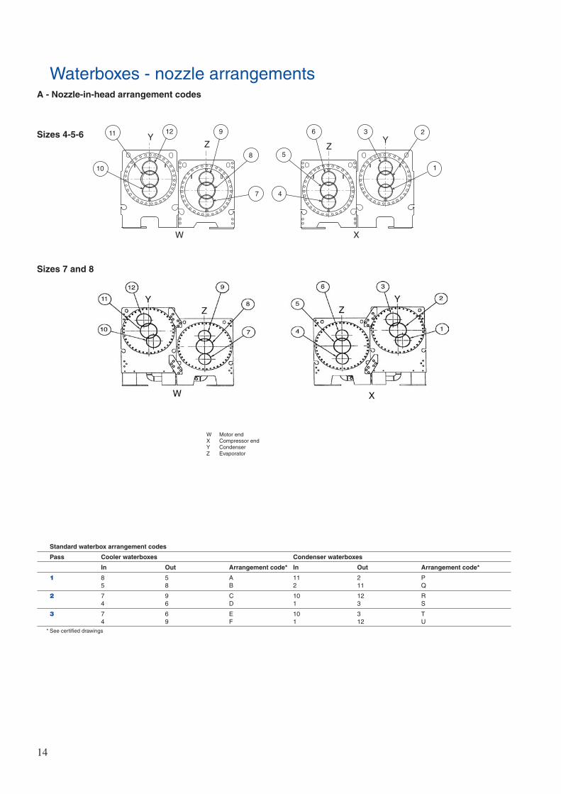
Waterboxes - nozzle arrangementsA - Nozzle-in-head arrangement codes
YZ Y
Z
10
11 12 9
8
7
5
6 2
1
W X
4
3
W Motor endX Compressor endY CondenserZ Evaporator
Standard waterbox arrangement codes
Pass Cooler waterboxes Condenser waterboxes
In Out Arrangement code* In Out Arrangement code*
1 8 5 A 11 2 P5 8 B 2 11 Q
2 7 9 C 10 12 R4 6 D 1 3 S
3 7 6 E 10 3 T4 9 F 1 12 U
* See certified drawings
Sizes 4-5-6
Sizes 7 and 8

15
B - Marine nozzle arrangement codes
Waterbox arrangement codes
Pass Cooler waterboxes Condenser waterboxes
In Out Arrangement code In Out Arrangement code*
1 8 5 A - - -5 8 B - - -
2 7 9 C 10 12 R4 6 D 1 3 S
3 7 6 E - - -4 9 F - - -
* See certified drawings
Waterbox arrangement codes
Pass Cooler waterboxes Condenser waterboxes
In Out Arrangement code In Out Arrangement code*
1 9 6 A - - -6 9 B - - -
2 7 9 C 10 12 R4 6 D 1 3 S
3 7 6 E - - -4 9 F - - -
* See certified drawings
W Motor endX Compressor endY CondenserZ Evaporator
Size 3
Sizes 4-5-6

16
B - Marine nozzle arrangement codes (cont.)
Waterbox arrangement codes
Pass Cooler waterboxes Condenser waterboxes
In Out Arrangement code* In Out Arrangement code*
1 8 5 A - - -5 8 B - - -
2 7 9 C 10 12 R4 6 D 1 3 S
3 7 6 E - - -4 9 F - - -
* See certified drawings
W Motor endX Compressor endY CondenserZ Evaporator
Sizes 7 and 8

17
Technical description
■ Water-cooled packaged liquid chiller for indoor installation,equipped with numerical control, and operating withchlorine-free refrigerant HFC-134a.
■ Regulations◆ The unit characteristics must be published in accordance
with ARI standards.◆ The machines with CE marking must comply with the
following European directives:- Pressurised equipment directive (PED) 97/23/EC- Machinery directive 98/37/EC, modified- Low voltage directive 73/23/EEC, modified- Electromagnetic compatibility directive 89/336/EEC,
modified and the applicable recommendations ofEuropean standards:
- Machine safety: electrical equipment in machines, generalregulations, EN 60204-1
- Electromagnetic emission EN 50081-2- Electromagnetic immunity EN 50082-2.
■ Quality assurance◆ The unit shall be designed, manufactured and tested at a
facility with a quality assurance system certified ISO 9001.◆ The unit shall be manufactured at a facility with an
environment management system certified ISO 14001.◆ The unit must satisfy the quality control tests in the factory
(pressure and electrical tests).
■ Designed to ensure maximum compliance with Europeanstandard EN 60 204-1 (electrical safety), EN 50082-2 (EMCimmunity), EN 50081-2 (EMC emissions) and with EN 378(safety).
Compressor
■ One centrifugal compressor of the high-performance, single-stage type. Connections to the compressor casing use O ringsinstead of gaskets to reduce the occurrance of refrigerantleakage.
■ The open type impeller with machined shroud contours andimpeller diameter optimize compressor efficiency for eachspecified application.
Cooler and condenser
■ Tubing is copper, high-efficiency type, with integral internaland external enhancement. Tubes are nominal 3/4-in. ODwith nominal wall thickness of 0.635 mm measured at theroot of the fin. Tubes are rolled into tube sheets and areindividually replaceable. Tube sheet holes are doublegrooved for joint structural integrity. Intermediate supportsheet spacing does not exceed 914 mm.
■ Waterboxes and nozzle connections are designed for 1034kPa maximum working pressure unless otherwise noted.Nozzles have grooves to allow use of Victaulic couplings.
■ The tube sheets of the cooler and condenser are boltedtogether to allow for field disassembly and reassembly.
■ Waterboxes have vents, drains, and covers to permit tubecleaning within the space shown on the drawings. Athermistor type temperature sensor is factory installed in eachwater nozzle.
■ The heat exchangers display a European code nameplatewhich shows the pressure-temperature data. A pressure reliefvalve is installed on each heat exchanger. A pressure reliefvalve device is installed on each heat exchanger whichpermits verification of the set point without transfer of thecharge.
■ Cooler is designed to prevent liquid refrigerant from enteringthe compressor.
■ Tubes are individually replaceable from either end of the heatexchanger without affecting the strength and durability of thetube sheet and without causing leakage in adjacent tubes.
■ The condenser shell includes a FLASC (flash subcooler)which cools the condensed liquid refrigerant to a reducedtemperature, thereby increasing the refrigeration cycleefficiency.
Starter, auxiliary box and control box
■ Galvanized sheet steel, polyester paint finish, colour lightgrey, with hinged access doors, containing:
◆ Starter (option) ◆ Auxiliary box includes control transformer for the CVC,
and the oil heater. ◆ Control box includes the processor board and the Human
Interface (CVC).
Control functions
■ Set point functionThe control provides the capability to view and change theleaving chilled water set point, entering chilled water setpoint, and demand limit set point at any time during chilleroperating or shutdown periods. The controls allow for thespecification of capacity control by either leaving chilledwater or entering chilled water.
■ Service functionThe control provides a password protected service functionwhich allows authorized individuals to: ◆ View an alarm history file which contains the last 25
alarm/alert messages with time and date stamp. Thesemessages are displayed in text form, not codes.
◆ Execute a chiller controls test function for quickidentification of malfunctioning components
◆ View/modify chiller configuration ◆ View/modify chiller occupancy periods ◆ View/modify schedule holiday periods◆ View/modify schedule override periods ◆ View/modify system time and date
■ Lead/lag functionLead/lag function automatically controls two chillers,including the reversing sequence. A third chiller can be added to the lead lag system as astandby chiller.
■ CommunicationInterface with other CCN devices is available as standard. ACCN/JBus (Carrier Comfort Network) interface facilitatescommunication with other BMS systems.

18
Typical piping and wiring
7
8
12
16
13
141415
17
18
19
3
19XR Chiller with optional unit-mounted starter
1. Disconnect2. Unit mounted starter with control
(factory-installed)3. Guide vane motor4. Oil pump terminal box5. Vents6. Pressure gauges7. Chilled water pump8. Condenser water pump9. Chilled water pump starter10. Condenser water pump starter11. Cooling tower fan starter12. To cooling tower13. From cooling tower14. To load15. From load16. Drain17. Piping18. Control wiring19. Power wiring
Important: Ensure correct phasing is followed for proper motor rotation.
Notes:1. Wiring and piping shown are for general point-of-connection only and are not intended to
show details for a specific installation. Certified field wiring and dimensional diagrams areavailable on request.
2. All wiring must comply with applicable codes.3. Refer to Carrier System Design Manual for details regarding piping techniques.4. Wiring not shown for optional devices such as:
• remote start-stop • remote alarm• optional safety device • 4 to 20 mA resets • optional remote sensors

19
Typical piping and wiring (cont.)
1718
15
19
1616
20
21
22
1. Disconnect 2. Freestanding compressor motor starter3. Compressor motor terminal box 4. Oil pump terminal box5. Control cabinet 6. Vents7. Pressure gauges 8. Chilled water pump9. Condenser water pump 10. Chilled water pump starter 11. Condensing water pump starter 12. Cooling tower fan starter 13. Disconnect 14. Oil pump disconnect (see note 5)15. To cooling tower16. From cooling tower17. To load18. From load19. Drain20. Piping21. Control wiring22. Power wiring
Notes:1. Wiring and piping shown are for general point-of-connection only and are not intended
to show details for a specific installation. Certified field wiring and dimensional diagramsare available on request.
2. All wiring must comply with applicable codes.3. Refer to Carrier System Design Manual for details regarding piping techniques.4. Wiring not shown for optional devices such as:
• remote start-stop • remote alarm• optional safety device • 4 to 20 mA resets • optional remote sensors
5. Oil pump disconnect may be located within the enclosure of item 2 - free-standingcompressor motor starter.
19XR Chiller with free-standing starter

Order No. 11995-20, 05.2004. Supersedes order No: 11995-20, 01.1998. Manufactured by: Carrier SA, Montluel, France.Manufacturer reserves the right to change any product specifications without notice. Printed on Totally Chlorine Free Paper.The cover photo is solely for illustration purposes, and is not contractually binding. Printed in the Netherlands.