evaporator-crystalliser, - issct - international society ... langreney true continuous... ·...
TRANSCRIPT
I
Factory Engineering
TRUE CONTINUOUS CRYSTALLISATION. 1. DESIGN STAGES. 2. INDUSTRIAL APPLICATION
Fraiqois Langreney
Sucreries de Bourbon, RCunion, Mauritius
ABSTRACT
This paper is presented in two parts. In the first, the author describes the evolutive design of a con-
tinuous, compartmentless evaporator-crystalliser. The results obtai- ned, and the changes brought about in the design during the first two years of trial, are given, and an explanatory description of the operation on an industrial scale, during the third year, is made.
In the second part, the author expresses his views on the ideal adaptation of this continuous crystalliser to cane sugar processing, and on the advantages which can be obtained with this new equipment.
INTRODUCTION
In 1968 a well-known manufacturer of sugar machinery announced the commissioning of continuous vacuum pans. Two of these new pans had been dade, and were operating satisfactorily on high purity products; one had been erected in a sugar refinery, and the other in a beet sugar factory.
This development was very important because it heralded the disap- pearance of the last batch operation still left in the processing of sugar.
These pans were divided into several compartments (multi-compart- ment system), virtually corresponding to unit vacuum pans operating in series, each one having its own automatic feed control. It is recognised that, in this type of pan, it is the motion in each cell which produces a good homogeneous massecuite, therefore a minimum number of compart- ments must be provided in order to obtain a predetermined coefficient of variation (CV) .
Other continuous vacuum-pans, based on the same or a slightly dif- ferent principle, have since been designed and tested. They were described by P.G. Wright1 in 1974.
The basic concept of the author,'was to develop a free-flow, or compart- mentless, evaporator-crystalliser, in order to realise a true continuous operation. To improve it he decided that the ratio of length to cross-section should be made the highest possible, in order to reduce to a minimum the effect of crystal dispersion due to motion.
2
2427 1

FACTORY ENGINEERING
In 1973, during the first congress held by the "Association Reunion- naise de Technologie Agricole et Sucrihre" (ARTAS), the authofl described the design of the pan he had in mind. In 1974, an industrial size prototype was built, and installed at Beau Champ Sugar Factory (Mauritius). This unit was tested'duridg the 1974 and 1975 crops, and has since been transfer- red to Stella Sugar Factory (RCunion) for regular operation (1976 crop).
DESIGN STAGES
Preliminaries
The crystallises had to satisfy three main criteria:
Theoretical : If I
- true continuous operation should be achieved, i.e. no cells should be constituted in the vessel;
- physical operating conditions should be optimal, by making the cross-sectional headlosses the lowest possible, in order to obtain the highest evaporation rate.
Pratical :
- it should be versatile, that is, it should be able to boil any type of massecuite;
- it should be built by assembling simple and fully tested components; I
- it should be realiable when handling any type of massecuite, and at various flow rates.
Economical : I "$4'
- manufacturing cost should be reasonable; I I
- it should be capable of further use in case of increased production.
Description 1 I A cross-section of the pan built in 1974 is shown in Fig. 1. It includes: ! I (a) Two vertical side-plates. 1 (b) Two senzi-cylindrical bottom plates.
(c) A semi-cylindrical top plate. I
I (d) A calandria common to circuits No 1 and 2.
(e) A longitudinal dividing plate separating circuit 1 from circuit 2. I
( f ) Two longiludiilal gutters fitted with spouts.

(g) Close to one another, for syrup or molasses feed. These gutters could be slightly tilted lengthwise.
(h) Corrugated sheeting, laid directly on the side-plates, constituted, in the corrugations, a series of vertical ducts.
(i) Tie-beams.
t ]FIGURE 1. Cross-section of the pan before trials at Beau Champ, in 1974.
Tiis vacuum pan was 5 meters long, which gave a total rnassecuite
travel distance of 10 meters; it had an effective volume of 10 cubic meters,
and 100 square meters heating surface.
Following the first trials in 1974, dispersion of the crystals did not
reach expectations; it was therefore decided to fit cross baffles, 2 a (Fig. 2) ,
every 50 cm, in order toliprevent mixing of crystals by surface splashing. ' i i ' " , i
/ 0
(1, ,,

2430 FACTORY ENGINEERING
FIGURE 2. Cross-section of the pan after trials at Beau Champ.
Although basically satisfactory, the internal open feeding system was too low, and this often caused trouble by massecuite clogging.
Modifications were carried out in 1974 and 1975 and, after a full season's trial on an industrial scale, have now been definitely adopted. The cross-section shown in Fig. 2 bears the same basic features except for the following :
2a) Cross-baffles fitted.
2b) Two longitudinal closed feeding mains, fitted with internal overflow piping delivering the leed underneath the calandria. "
2c) Flexible connections to allow for adjustment of the longitudinal inclination of the mains (2b).
2d) Separate feed pipes placed every 25 cmn alongside the pan wall.
In Fig. 3 are shown cross sectional and plan views of industrial sized pans of up to 50 1n3 working capacity and, in Fig. 4, the general layout a complete continuous crystallisation plant.

F. LANGRENEY
FIGURE 3 . Cross-sectional and plan views of Industrial pan up to 50 1113.
Type 2D Type 4D
L Heating Volume L Heating Volume (m) Surface (mz) (m') ( m ) Surface (m2) (m')
5 125 12,500 .5 250 25 -- 6 150 15,000 6 300 30 --
7 175 17,500 7 350 35
8 200 20,000 8 400 40
9 225 22,500 9 450 45 --
10 250 25.000 10 500 50


i
F. LANGRENEY
Operation
The pan is designed to produce massecuite from either inagma or seed crystals, prepared in another vacuum pan, as footing. An appropriate grain- ing method to suit this pan will be developed in the course of coming years.
Footing is introduced at one end of the massecuite travel circuit by means of a variable-speed feed pump. Footing feed rate is proportional to its crystal content, and to the final crystal size that is required.
Steam introduced in the calandria creates a therino-siphonal effect, which gives rise to transversal circulation in the pan.
Introduction of dry matter with the syrup or molasses along the vessel, causes massecuite level to rise; an overflow weir situated at the outlet end of the massecuite travel circuit, maintains the level constant.
Transversal and longitudinal motions being very distinct from each other, give to this pan its versatile properties.
Boiling of C massecuite can be performed manually, but it is preferable to provide automatic control of all parameters, namely: steam pressure, vacuum and supersaturation. This is particularly recommended with high purity products.
Results
During the first two years of trials at Beauchamp, no steam or vacuum regulation was provided, only supersaturation was controlled throughout.
The pan performed as expected, but crystals were not uniform and the internal feeding gear was not fully reliable. As a result, modifications described in Fig. 2 were carried out, and the difficulties were eliminated.
Nearly all the trials during the first two years were made on C mas- secuite because it could be left without inconvenience in the pan during stoppages. Good crystallisation results were also obtained, when the pan was run for a few hours on A massecuite.
Although figures obtained at Beauchamp were not conclusive, the following features have been observed: - Output was in most cases at least 50% higher than that of conventional vacuum pans of the same nom- inal dimensions; a very tight massecuite could easily be produced and, at discharge, purity ol the mother liquor was always one or two points lower than that of conventional pans.
Following installation of the continuous pan in Stella Factory (Re- union) in 1976, systematic tests to determine output, mean aperture (MA) and coefficient of variation,have been carried out. Results are given in Table I.
8 * ! ,

TABLE I . Comparative results on "C" Massecuite Stella d u ~ ring the last four years.
(1) Refractometri c Brix (2) Apparent Purity (3) Clerget Purity (4) Target Purity ( 40 - 4 R )
C (5) F i r s t 14 weeks of the crop
*
Year
1973
1974
1975
1976 (5)
3 Mean C . V . obtained Mean C.V. obtained
in the foo in the "C"
Mean C . V .
ting i'n 1976 . . . . . . . . . . . 39,05 Massecuite in 1976 .. . . 32,61
Final Molasses Sucrose los t in final molasses
% Canne Brix Purity (3) Targe14Purity A Purity (% sucrose)
3 , I4 84,58 43,8 37,62 6 318 8,63
3,18 84,32 43,3 36,70 6,60 8,54 --- . ^
3,23 84,37 43,8 37,9 5,90 8,50 ' -"
3,13 85,35 42,9 37,65 5,23 8,22
C Massecuite
Difference . . . . . . . . . . . . 6,44
Brix (1)
95,87
96,49
96,48
95,43
Purity (2)
59,6
59,l
59 ,O
57,43

FIGURE 5. Seeding of C massecuite.
FIGURE 6 . C nlassecuite obtained from the seeding shown in Fig. 5.

FACTORY ENGINEERING
FIGURE 7 . General arrangement of the pilot plant at Beau Champ.
INDUSTRIAL APLICATION
General Considerations
FIGURE 8. General arrangement of Stel- la.
Will continuous operation in crystallisation simply mean replacement of conventional pans by coi~tii~uous ones? I
Our reply to this question is: certainly not. Industrial application of true continuous boiling will bring about important changes in the design 1 and operation of pan stations. i

We shall now try to foresee the advantages and drawbacks ol this new technique.
I Advantages and drawbacks relative to tlze plant
Reduction in pan volume.
In a conventional pan, during the boiling cycle, only part of the 1 available volumetric capacity is utilised; by contrast, a continuous pan always
operates at maximum capacity: therefore, it requires a smaller volume for a corresponding output.
Consider a conventional pan which starts with q cubic meters of foot- ing, to end up, after n hours boiling time, with Q cubic meters of massecuite. During the boiling cycle, it will gradually fill up, but before its full nominal volume of Q cubic meters is reached, a certain part will remain unused.
By coqparison, the nominal volun~e Q' of a continuous pan is always fully used.
What percentage of the volume of a conventional pan is this equivalent to?
In order to simplify the calculation, let us assume that the amount of massecuite produced bears a direct linear relationship to the time factor. This assumption is not quite true, but sufficiently correct for the purpose of this study.
Thus, the continuous pan volun~e, equivalent to that of a 100 HL conventional one using 30 HL of footing, will be:
30 + loo - 30 = 65 HL or 65% of the volume of the 2 conventional pan.
A second significant volun~e reduction is represented by the time saved on stoppages of the conventional pan for discharging at the end of each cycle. The percentage gain can easily be calculated, and the consequent reduction established.
A third factor which will further contribute to volume reduction, is the operating efficiency of the continuous pan; this is due mainly to its ability to maintain, very steadily, higher temperature and supersaturation values, without running any risk of false grain formation or massecuite deterioration because of its excellent circulation characteristics.

2438 FACTORY ENGINEERING
Combination of these various factors gives to the continuous pan a capacity practically double that of a conventional one of the same nominal volume.
Reduction of pan auxiliaries.
In continuous pans elimination ol output peaks and stoppages, peculiar to batch-types, causes a reduction in size of various pumps, condensers, cooling plants, storage tanks, and even the suppression of discharge receivers.
EfIects of this reduction in equipment will be felt at the evaporator station, and even at the steam boilers.
Increase in Control Equipment.
It is quite possible to operate the continuous pan described in part 1 of this paper, manually. But to design an industrial continuous pan station without providing it with steam, vacuum and supersaturation control, is inconceivable.
Most factories are now equipped with one or all of these controllers and nearly every pan operator is well acquainted with them. Controllers become an absolute necessity, when high, steady predesigned performances are wanted, particularly because their reliability in operation is never a cause for worry.
That turbo-alternators need to be fitted with complicated high precision controls, in order to maintain perfect stability of the supply voltage and frequency, is a normally accepted fact; yet a 2 to 3% variation in their value will certainly not bring about any loss of sugar, although it is very doubtful, that factory managers would tolerate a 2 to 3% variation in the brix of C massecuite. 9
The continuous pan, equipped with appropriate controls, will turn out massecuite of pre-determined Brix, with less than r+. 0,25 variatiqn.
x+!;,',
Process advantages
Unlike the advantages brought about by the equipment itself-which can easily be listed and estimated- advantages that true continuous boiling brings to the process are less obvious, but certainly very important.
Unlike continuous clarification and filtration which positively caused inconveniences when adapted to processing - mainly for economical reasons - continuous crystallisation can only be beneficial.
During recent deca'des, steam temperatures have been steadily increas- ing, not only for the improvement of the factory thermal balance, but also because reciprocating engines have been replaced by steam turbines which deliver higher exhaust pressures.
If this temperature rise is not very i~nportant for sugar products that are in direct contact with the metallic heating wall for a relatively small time, as occurs through the heaters and in the evaporators, this is not the case for conventional pans. In these, sugar products containing a high percentage of unstable, quick-to-react and easily destroyed organic im- purities, are subjected to superheating for a long time.
This is quite obvious, when the attractive aspect of a C massecuite I - always less viscous at the same brix - coming from a continuous pan , I is compared with that discharged by a conventional one; it can be clearly
observed - without having to use elaborate analytical methods - that the
I effects of overheating are very important.
On the other hand, practice quickiy proves that massecuite can be maintained at higher temperature, without notable change to its aspect.
This rise in temperature will Iavour an increase in specific crystallisation rate, and the formation of a harder type of crystal.
I Due to its high surface/volume ratio, ranging between 8 and 10 m2/ m3, it is possible to work the continuous pan's massecuite at pre-selected temperatures while making use of a very low temperature heating steam.
I i Recommended values for the three strikes are the following:
. . . . . . . . . . . ! ! A Massecuite 108OC
. . . . . . . . . . . ! I B Massecuite 106OC
. . . . . . . . . . . I J C Massecuite 104OC
(? At these temperatures it is very likely that less melassigenic substances I
will be formed during crystallisation; thus, exhaustion of molasses will be improved, and consequently sugar recovery as well. Such low temperatures will also result in a saving for the factory's heat balance.
I I Circulation. I
I The cross-section of the continuous pan having been designed to reduce the heat-losses to a minimum, massecuite circulation is always very good;
I crystal quality and crystallisation rate show a marked improvement over I those of the batch-type pan.
i

FACTORY ENGINEERING I Supersaturation.
In practice, the molasses and syrup feeding system, being controlled throughout the massecuite progression across the vessel, favours good continuous panwork; consequently, near-to-maximum supersaturation levels and very high crystallisation rates are reached.
Practical -observations
Combination of all these factors, by improving crystallisation rate and preservation of elaborated products, will provide a better quality sugar and a higher recovery value, during a shorter crystallisation time.
It has also been observed that it is possible, with the continuous pan, to strike out low grade massecuite at a considerably lower purity, the crystallisation rate being almost unaffected. The conventional C massecuite purity of 60 can be lowered to 50, or even less.
As a result, it will become possible, in the three-boiling system, to take full advantage of the total purity drop, by contrast with what has been done up to now when - through the use of higher purity products to raise B & C massecuite purities -,')only part of this drop was being used. ' I
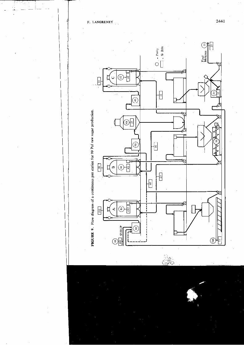
In certain cases, namely when juice purity was around 80' to 83, the two boiling system was adopted. With continuous crystallisation, this system except when maximum recovery of sugar is not aimed at, become pur- pose less.
Flow diagram for continuous three boiling system I Fig. 9 illustrates the flow diagram of a continuous pan station for
99 Pol raw sugar manufacture. , a _ I
1 "A" massecuiie is struck from a 90 purity magma footing, prepared ~ from B sugar and clarified juice, fed with syrup that has been topped up with A molasses in order to keep the massecuite purity at 85. In white 1 sugar manufacture, with a view to producing a better quality sugar, this purity can be raised to 87/88.
The raw sugar massecuite is then cured hot; it is preferable for white sugar to cool down to achieve better exhaustion, the aim, in both cases, being to obtain 68 purity A-molasses.
For the tiqe being, curing of this massecuite will be carried out in batch type centrifugals, which will turn out the total amount of commercial
I sugar. Boiled almost completely from syrup and in part from B sugar footing, this sugar will be of high quality and the crystals uniform. ,
F. LANGRENEY

2442 FACTORY ENGINEERING
" A molasses will have a twofold use: firstly for the preparation of a footing common to B and C massecuites. "A" molasses at 68 purity is an excellent medium for seeding, and all B and C footings will be raised in the only batch pan left on the pan floor. To avoid the variable quality usually observed in footings, boiled manually by panmen, this pan should be equipped with a fully automatic boiling controller of which several makes are available at reasonable prices.
"B" massecuite would no langer be intended for commercial sugar production, but would become an exhaust-purpose massecuite. It would therefore be made in a continuous pan, from the common footing, and fed with A molasses only. With a purity almost identical to that of A molasses, i.e. between 65 and 70, the B massecuite, following its passage through water cooled crystallisers, should be cured in continuous centrifugals equip- ped with extra large diameter casings, to avoid crystal breakage.
Sugar discharged at around 92 purity by these centrifugals will, after mixing with clarified juice, be used as footing for A massecuite. B sugar crystals would have to be sufficiently big to produce A sugar of desirable commercial size. Any excess of B sugar would have to be remelted.
With this B strike, a large purity-drop will be obtained because of cooling down in crystallisers and curing in continuous centrifugals with very little wash water. Starting with 70, a 25 point drop can be expected, therefore 45 B molasses can be obtained.
From the 70 purity commpn footing and these 45 purity molasses, and according to their exact purity and proportions, a 50 to 55 purity C massecuite will also be raised in a continuous pan.
This massecuite, after cooling, will be passed through continuous centrifugals, and the resulting C sugar, at about 85 purity, should be remelt~d and mixed with incoming syrup from the evaporation. L?' d
The flow diagram that has been presented is simple, straight-forward and sound, processwise. By following it, the best commercial sugar can be obtained, boiling back of molasses is avoided, and the highest recovery of sugar can be achieved, all without additional equipment. In Reunion, it is already partially or completely used in several factories, and has given very satisfactory results.
CONCLUSION
Adoption of continuous sugar boiling in the cane sugar 'factory is now possible, and its advantages when compared with the present batch system are unquestionable.

F. LANGRENEY 2443
These advantages, and their return on equipment, can now be esti- mated, but it is only future practical results which will show the benefits that are to be derived from precautions taken, to process solutions as easily spoiled as syrups and molasses can be.
It is obvious that satisfactory batch pans should not be discarded as long as they renqain profitable, but it is wise to tend to a fully continuous pan station when their gradual replacement is planned. These changes should start with low grade products, probably the most profitable section.
In the evolution of this part of the factory, the human factor must not be overlooked. Replacement ol the last skilled artisan still remaining in the factory, the panman, by a real process technician of higher level, will follow.
The latter will, at last, have at his disposal a well designed station, that will enable hinl to apply the theoretical crystallisation principles well known to all of us, but rarely put into practice, because of inadequate equipment.
REFERENCES
1. P.G. Wright. (1974). Vacuum Fans - Batch and continuous. Sugar Technology Reviews - Elsevier - Vol. 2 N.O 2, p, 137.
2 . F. Langreney. (1973). Nouvelle approche pour la realisation d'un appareil h cuire continu. Revu Agricole et Sucrikre de Maurice - Vol. 52 N.O 4, p. 298.
3. L. Lenard, B. Ilufrenne. (1975). Mesures de la granulometrie du sucre dans les masses-cuites. La Sucrerie Belge - Vol. 94, p. 3.
CRISTALIZACION CONTINUA. 1. ETAPAS DE DISERO. 2. APLICACION INDUSTRIAL
F. Langreney
RESUMEN
Este estudio esta presentado en dos partes. En la primera parte el autor describe la evoluci6n del diseiio del
cristalizador evaporador continuo sin compartirnientos. Los resul- tados obtenidos, y 10s cambios hechos al diseiio durante 10s pri- meros dos aiios en experiencias, se presentan, y se hace una descripcion explicatoria de la ~ p e r ~ c i o n en escala industrial durante el tercer aiio.
En la segunda parte, el autor exprgsa,sus puntos de vista en la adaptacion ideal de su cristalizador continuo al procesamiento de la caiia de az~lcar, y las.ventajas que pueden ser obtenidas con este nuevo equipo. i
<