evaluation on edge-supported magnetic levitation apparatus
TRANSCRIPT

11Journal of the Magnetics Society of Japan Vol.43, No.1, 2019
INDEX
J. Magn. Soc. Jpn., 43, 11-16 (2019)<Paper>
Evaluation on Edge-supported Magnetic Levitation Apparatus for Thin Steel Plates
Y. Oda, Y. Ito, K. Okuno, M. Kida, T. Suzuki,
A. Endo, T. Narita*, H. Kato* and H. Moriyama* Course of Mechanical Engineering, Graduate School of Tokai Univ., 4-1-1 Kitakaname, Hiratsuka-shi, Kanagawa 259-1292, Japan
* Department of Prime Mover Engineering, Tokai Univ.
Grasping and conveying an object, by utilizing the frictional force generated by contact is performed in various processes in the manufacturing line for an industrial product. The deterioration of the surface quality due to these contacts is a problem. As a solution to this problem, a noncontact transport of steel plates, using electro-magnetic force, has been proposed. However, in these systems, electromagnets are installed vertically. In this method, if the steel plate is thin and does not have sufficient flexural rigidity, it is difficult to add a suspension force for levitation over the entire steel plate. In order to solve this problem, we proposed an edge supported electromagnetic levitation system for flexible steel plates using electromagnets installed horizontally. In order to verify the effectiveness of the proposed system we constructed a prototype of an edge-supported type magnetic levitation system, which applied electromagnetic force only from the horizontal direction of the steel plate. Consequently, we carried out levitation experiment and discussed characteristics of horizontal positioning and levitation suspension. Key words: electromagnetic levitation, thin steel plate, vibration control, magnetic field
1. Introduction
Thin steel plates are used in many industrial products and their transportation take place by contact with a large number of rollers in the manufacturing process. Recently, the demand of high quality steel is increasing. Therefore, the deterioration of the surface quality is a problem for this type of contact transportation. To solve this problem, the application of a magnetic levitation technology to a non-contact transport system is actively being studied1)-5). The authors' research group had installed electromagnets not only vertically but also horizontally. Vertical electromagnets’ levitation is applying tension to the steel plate edges. We have confirmed that horizontal electromagnets improve levitation stability in thin steel plates with extremely low flexural rigidity6)-7). Furthermore, they help realize advanced levitation control systems considering the steel plate deflection as well as the vibration characteristics. Levitation control using only electromagnets from the edge direction is important. Hitherto, we have confirmed the characteristics of the suspension force of the edge direction electromagnet acts on the steel plate by experiment and analysis8). In this study, we made a prototype edge supported electromagnetic levitation system based on these characteristics and we discuss the levitation characteristics.
2. Edge Supported Electromagnetic Levitation System
Figure 1 shows a schematic illustration of the newly
made edge supported electromagnetic levitation system. Figure 2 shows the placement of the electromagnet and the sensor view from the top. As Fig. 2 shown, the vertical direction is defined as Z direction, the longitudinal
Fig. 1 Edge supported levitation system for steel plate using only electromagnets installed horizontally.
direction of steel plate is defined as Y direction and the transverse direction is defined as X direction. Figure 3 shows a photograph of the electromagnetic levitation system during the levitation of a steel plate. The levitating object is a rectangular galvanized steel plate (material SS400) whose length is 400 mm, width is 100 mm, and thickness is 0.24 mm. In the electromagnetic levitation system, as shown in Fig. 4, two electromagnets facing each other are installed in the longitudinal direction near the edge of the thin steel plate. The attractive force of the electromagnets installed in the X direction, near the edge of the steel plate, perform non-contact positioning control. In a previous study7), we calculated the deflection shape using magnetic field analysis and the finite difference method. The electromagnets are installed at such position to minimize
A/D converterx2 x3x1 x4 i 1 i 4i 3i 2
AMP1AMP2AMP3AMP4
DSPiBIS 7101A 1.6GHz
D/Aconverter
ResistanceAmplifier
z1 z2
Steel plate( 400 mm × 100 mm × 0.24 mm)
Laser type sensor
Levitation and horizontalpositioning controller
Eddy current type sensor
Electromagnet for levitation and horizontal positioning control

12 Journal of the Magnetics Society of Japan Vol.43, No.1, 2019
INDEX
Fig. 2 Schematic illustration of the edge supported levitation system.
Fig. 3 Photograph of the electromagnetic levitation system.
deflection and to expect stability on the steel plate. A laser-type sensor, which measure the displacement by the cut -o f f amount o f a be l t - l ike laser beam manufactured by KEYENCE was used to measure the horizontal displacement in X direction of the edge of the steel plate. Thereby, the steel plate is controlled by non-contact positioning by the electromagnets at a distance of 5 mm from the edge of the steel plate. Furthermore, the control law is calculated by detecting the current in each electromagnet from the measured external resistance and, subsequently, inputting eight measurement values into a digital signal processor of an A/D converter. The core, shown in Fig. 5, is an E-type electromagnet, and the material is ferrite. The electromagnet ’s core is an enamel wire of 0.5 mm diameter wound around it 1005 times. For evaluating the
Fig. 4 Placement of electromagnet and displacement field sensor.
Fig. 5 Configuration of the electromagnet.
Fig. 6 Position of eddy current type noncontact displacement sensor.
levitating state of the steel plate, a vertical direction displacement sensor was installed as shown in Fig. 4 and Fig. 6. An eddy current non-contact displacement sensor manufactured by SENTEC was used. To consider the characteristic of suspension force generated by electromagnet, electromagnetic analysis was carried out. The analytical model is consisting of one electromagnet and steel plate (400 mm × 100 mm). The suspension force
Electromagnetic for levitation and horizontal positing control
Laser type sensor
Eddy current type noncontact displacement sensor
Steel plate
Z Y
X
Laser type sensor
Electromagnet for levitation and horizontal positioning control
Steel plate
400
mm
220
mm
100 mm
Y
X
8 8
14 16 60 16
28 36
Coil
Ferrite core
( 1005 turns )
[mm]
8 mmDisplacement zZ0=0 mm
Steel plate
ElectromagnetEddy current type noncontact displacement sensor
x
z
0
13Journal of the Magnetics Society of Japan Vol.43, No.1, 2019
INDEX
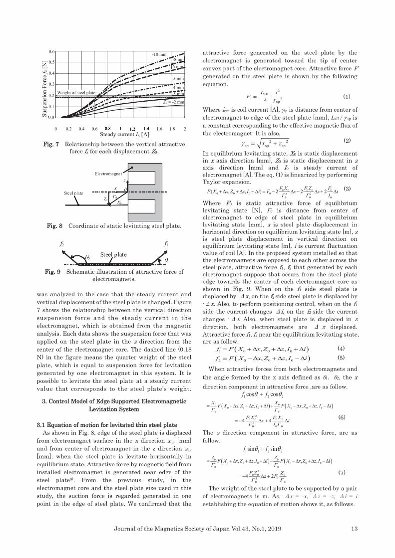
Fig. 7 Relationship between the vertical attractive force fz for each displacement Z0.
Fig. 8 Coordinate of static levitating steel plate.
Fig. 9 Schematic illustration of attractive force of electromagnets.
was analyzed in the case that the steady current and vertical displacement of the steel plate is changed. Figure 7 shows the relationship between the vertical direction suspension force and the steady current in the electromagnet, which is obtained from the magnetic analysis. Each data shows the suspension force that was applied on the steel plate in the z direction from the center of the electromagnet core. The dashed line (0.18 N) in the figure means the quarter weight of the steelplate, which is equal to suspension force for levitation generated by one electromagnet in this system. It is possible to levitate the steel plate at a steady current value that corresponds to the steel plate’s weight.
3. Control Model of Edge Supported ElectromagneticLevitation System
3.1 Equation of motion for levitated thin steel plate As shown in Fig. 8, edge of the steel plate is displaced from electromagnet surface in the x direction xsp [mm] and from center of electromagnet in the z direction zsp [mm], when the steel plate is levitate horizontally in equilibrium state. Attractive force by magnetic field from installed electromagnet is generated near edge of the steel plate8). From the previous study, in the electromagnet core and the steel plate size used in this study, the suction force is regarded generated in one point in the edge of steel plate. We confirmed that the
attractive force generated on the steel plate by the electromagnet is generated toward the tip of center convex part of the electromagnet core. Attractive force F generated on the steel plate is shown by the following equation.
2eff
2sp2
L iF
= (1)
Where iem is coil current [A], sp is distance from center of electromagnet to edge of the steel plate [mm], Leff / sp is a constant corresponding to the effective magnetic flux of the electromagnet. It is also,
2 2sp sp spx z = + (2)
In equilibrium levitating state, X0 is static displacement in x axis direction [mm], Z0 is static displacement in z axis direction [mm] and I0 is steady current of electromagnet [A]. The eq. (1) is linearized by performing Taylor expansion.
0 0 0 0 00 0 0 0 2 2
0 0 0
( , , ) 2 2 2F X F Z FF X x Z z I i F x z iΓ Γ I
+ + + = − − + (3)
Where F0 is static attractive force of equilibrium levitating state [N], 0 is distance from center of electromagnet to edge of steel plate in equilibrium levitating state [mm], x is steel plate displacement in horizontal direction on equilibrium levitating state [m], z is steel plate displacement in vertical direction on equilibrium levitating state [m], i is current fluctuation value of coil [A]. In the proposed system installed so that the electromagnets are opposed to each other across the steel plate, attractive force f1, f2 that generated by each electromagnet suppose that occurs from the steel plate edge towards the center of each electromagnet core as shown in Fig. 9. When on the f1 side steel plate is displaced by Δx, on the f2 side steel plate is displaced by -Δx. Also, to perform positioning control, when on the f1 side the current changes Δi, on the f2 side the current changes -Δ i. Also, when steel plate is displaced in z direction, both electromagnets are Δ z displaced. Attractive force f1, f2 near the equilibrium levitating state, are as follow.
( )1 0 0 0, ,f F X x Z z I i= + + + (4) ( )2 0 0 0, ,f F X x Z z I i= − + − (5)
When attractive forces from both electromagnets and the angle formed by the x axis defined as ,, the x direction component in attractive force ,are as follow.
1 1 2 2cos cosf f +
( ) ( )0 00 0 0 0 0 0
0 0
, , , ,X XF X x Z z I i F X x Z z I i
= + + + + − + −
20 0 0 0
30 0 0
4 4F X F Xx iI
= − + (6)
The z direction component in attractive force, are as follow.
1 1 2 2sin sinf f +
( ) ( )0 00 0 0 0 0 0
0 0
, , , ,Z ZF X x Z z I i F X x Z z I i
= + + + − − + −
20 0 0
030 0
4 2F Z Zz F
= − + (7)
The weight of the steel plate to be supported by a pair of electromagnets is m. As, Δx = -x, Δz = -z, Δi = i establishing the equation of motion shows it, as follows.
Z0 X0
Steel plate
Electromagnetz
x 0Γ0
f1f2
Steel plate
0.0
0.1
0.2
0.3
0.4
0.5 0.6
0 0.2 0.4 0.6 0.8 1 1.2 1.4 1.6 1.8 2
0.0Susp
ensio
n Fo
rce
f z [N
]
0.8 1 1.2 1.4Steady current Ix [A]
Weight of steel plate Z0 = -2 mm
-3 mm -4 mm -5 mm
-6 mm -8 mm
-10 mm

14 Journal of the Magnetics Society of Japan Vol.43, No.1, 2019
INDEX
220 0 0 0
2 30 0 0
4 4 0F X F Xd xm x idt I
+ − =(8)
220 0 0
02 30 0
4 2F Z Zd zm z F mgdt
+ = −(9)
At this time, taking the values of 0,Z0,F0 which satisfy the following equation, steel plate can be magnetically levitated.
00
0
2 0ZF mg
− = (10)
As described above, we obtained the motion of x direction by attractive force from facing electromagnet is depend on amount of change from stationary value of pair electromagnets, the motion of z direction is depending on stationary value of electromagnet. Therefore, in this paper, focusing only on the horizontal direction, a position control model is constructed with Z0 = z = 0,0 = X0.
3.2 Horizontal positioning control model Although the flexible thin steel plate exhibits elastic vibration in the vertical direction, it can be regarded as a rigid body in the X direction. The proposed system virtually divides the steel plate into two parts as shown in Fig. 10. We modeled the motion of the steel plate in the X direction using a 1-DOF model that actively controls each part. The same static attractive force is applied by the two installed electromagnets in order to sandwich the steel plate and, the equilibrium position of the steel plate is at the same distance from each electromagnet. The displacement of the steel plate from the equilibrium position is defined as x and the motion and circuit equations are as follows. Furthermore, the attractive force of the electromagnets at the equilibrium point was linearized.
(1)
(2)
(3)
(4)
Using the state vector, Eqs. (1)-(4) can be rewritten as follow.
(5)
Txx x i=x Txx x ixx x ix
x xx
x 0 x x
xeff x x2
x 0 x
0 1 0
4 40
02
F Fm X m I
L I RL X L
=
− −
A ,
Table 1 Coefficient of the control model.
T
xx
10 02L
=
B
where Fx is the magnetic force of the coupled magnets in the equilibrium state [N], X0 is the gap between the steel plate and the electromagnet in the equilibrium state [m], Ix is the current of the coupled magnets in the equilibrium state [A], ix is the dynamic current of the coupled magnets [A], Lx is the inductance of the magnet coil in the equilibrium state [H], Rx is the resistance of the coupled magnet coils [Ω], vx is the dynamic voltage of the coupled magnets [V], Lxeff/X0 is the effective inductance of the one magnet coil [H], and Lxlea is the inductance leakage of the magnet. Furthermore, vx is the feedback x, the state variable x and is expressed in the following equation.
v = −F xx x (6)
x x v if f f=F
4. Levitation Experiment of Steel Plate by EdgeSupported Electromagnetic Levitation System
4.1 Experimental conditions The steady current Ix of the electromagnet was varied.
In order to evaluate the levitating characteristics of the steel plate at that time, we carried out a magnetic steel plate experiment. The steel plate is supported by jack, and levitated by lowering the jack. The parameter that was used to design the control system is shown Table 1.
Symbol Value
X0 5×10⁻³ m
Lxeff 1.25×10⁻⁵ H
Lxlea 1.89×10⁻¹ H
Lx 1.92×10⁻¹ H
Rx 10 Ω
mx 3.74×10⁻² kg
fx fv fi
1.04×10³ 3.66×10² 4.2×101
xeffx xlea
0
LL LX
= +
x xx x
0 x
4 4F Ff x iX I
= +
xeff x xx x x2
x 0 x x
12 2
L I Rd i x i vdt L X L L
= − − +I Ri x i vx xi x i vx xI Ri x i vI Rx xI Rx xi x i vx xI Rx x
x x xx x xi x i vx x xdt L X L Lx x xdt L X L Lx x x2 2dt L X L L2 2x x x2 2x x xdt L X L Lx x x2 2x x xi x i v= − − +i x i vi x i v= − − +i x i vx xi x i vx x= − − +x xi x i vx xx x xi x i vx x x= − − +x x xi x i vx x x
= +x A x B vx A x B v= +x A x B v= +x x x
Table 2 Feedback gain of Fx.
Fig. 10 Experimental model of electromagnetic suspension force.
1 2 xmx f f f= − =4 44 4F F4 4
1 2 xmx f f f1 2 xmx f f f1 2 xmx f f f= − =mx f f f
f1
mx
x
Ix + ix
Steel plate (rigid body)
Electromagnet for levitation and horizontal positioning control
Laser type sensorIx + ix
mxf2
15Journal of the Magnetics Society of Japan Vol.43, No.1, 2019
INDEX
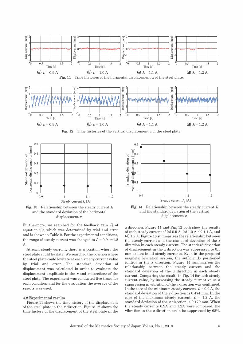
(a) Ix = 0.9 A (b) Ix = 1.0 A (c) Ix = 1.1 A (d) Ix = 1.2 A Fig. 11 Time histories of the horizontal displacement x of the steel plate.
(a) Ix = 0.9 A (b) Ix = 1.0 A (c) Ix = 1.1 A (d) Ix = 1.2 A
Fig. 12 Time histories of the vertical displacement z of the steel plate.
Furthermore, we searched for the feedback gain Fx of equation (6), which was determined by trial and error and is shown in Table 2. For the experimental conditions, the range of steady current was changed to Ix = 0.9 ~1.2 A.
At each steady current, there is a position where the steel plate could levitate. We searched the position where the steel plate could levitate at each steady current value by trial and error. The standard deviation of displacement was calculated in order to evaluate the displacement amplitude in the x and z directions of the steel plate. The experiment was conducted five times for each condition and for the evaluation the average of the results was used.
4.2 Experimental results Figure 11 shows the time history of the displacement of the steel plate in the x direction. Figure 12 shows the time history of the displacement of the steel plate in the
z direction. Figure 11 and Fig. 12 both show the results of each steady current of (a) 0.9 A, (b) 1.0 A, (c) 1.1 A, and (d) 1.2 A. Figure 13 summarizes the relationship between the steady current and the standard deviation of the x direction in each steady current. The standard deviation of displacement in the x direction was suppressed to 0.1 mm or less in all steady currents. Even in the proposed magnetic levitation system, the sufficiently positioned control in the x direction. Figure 14 summarizes the relationship between the steady current and the standard deviation of the z direction in each steady current. Comparing the results in Fig. 14 for each steady current value, by increasing the steady current value a suppression in vibration of the z direction was confirmed. In the case of the minimum steady current, Ix = 0.9 A, the standard deviation of the z direction is 0.474 mm. In the case of the maximum steady current, Ix = 1.2 A, the standard deviation of the z direction is 0.179 mm. When the steady currents 0.9A and 1.2A were compared, the vibration in the z direction could be suppressed by 62%.
0 0.5 1 1.5 2-2
-1
0
1
2
Time [s]
Disp
lacem
ent [
mm
]
0 0.5 1 1.5 2-2
-1
0
1
2
Disp
lacem
ent [
mm
]
Time [s]0 0.5 1 1.5 2-2
-1
0
1
2
Time [s]
Disp
lacem
ent [
mm
]
0 0.5 1 1.5 2-2
-1
0
1
2
Time [s]
Disp
lacem
ent [
mm
]
0 0.5 1 1.5 2-2
-1
0
1
2
Time [s]
Disp
lacem
ent [
mm
]
0 0.5 1 1.5 2-2
-1
0
1
2
Time [s]
Disp
lacem
ent [
mm
]
0 0.5 1 1.5 2-2
-1
0
1
2
Time [s]D
isplac
emen
t [m
m]
0 0.5 1 1.5 2-2
-1
0
1
2
Time [s]
Disp
lacem
ent [
mm
]
Fig. 13 Relationship between the steady current Ix and the standard deviation of the horizontal
displacement x.
Fig. 14 Relationship between the steady current Ix and the standard deviation of the vertical
displacement z.
0
0.1
0.2
0.3
0.4
0.5
0.9 1 1.1 1.2
Stan
dard
dev
iatio
n of
verti
cal d
ispl
acem
entz
[mm
]
Steady current Ix [A]
0
0.1
0.2
0.3
0.4
0.5
0.9 1 1.1 1.2
Stan
dard
dev
iatio
n of
ho
rizon
tal d
ispl
acem
ent x
[mm
]
Steady current Ix [A]
16 Journal of the Magnetics Society of Japan Vol.43, No.1, 2019
INDEX
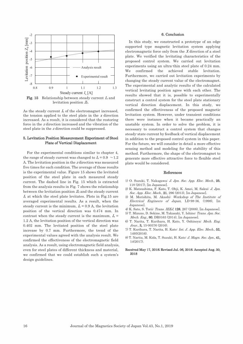
Fig. 15 Relationship between steady current Ix and
levitation position Z0. As the steady current Ix of the electromagnet increased, the tension applied to the steel plate in the x direction increased. As a result, it is considered that the restoring force in the z direction increased and the vibration of the steel plate in the z direction could be suppressed. 5. Levitation Position Measurement Experiment of Steel
Plate of Vertical Displacement For the experimental conditions similar to chapter 4, the range of steady current was changed to Ix = 0.9 ~1.2 A. The levitation position in the z direction was measured five times for each condition. The average of those results is the experimental value. Figure 15 shows the levitated position of the steel plate in each measured steady current. The dashed line in Fig. 15 which is extracted from the analysis results in Fig. 7 shows the relationship between the levitation position Z0 and the steady current Ix at which the steel plate levitates. Plots in Fig.15 are averaged experimental results. As a result, when the steady current is the minimum, Ix = 0.9 A, the levitation position of the vertical direction was 0.474 mm. In contrast when the steady current is the maximum, Ix = 1.2 A, the levitation position of the vertical direction was 0.402 mm. The levitated position of the steel plate increase by 0.7 mm. Furthermore, the trend of the experimental values agreed with the analysis result. We confirmed the effectiveness of the electromagnetic field analysis. As a result, using electromagnetic field analysis, even for steel plates of different thickness and material, we confirmed that we could establish such a system’s design guidelines.
6. Conclusion
In this study, we constructed a prototype of an edge supported type magnetic levitation system applying electromagnetic force only from the X direction of a steel plate. We verified the levitating characteristics of the proposed control system. We carried out levitation experiments using an ultra-thin steel plate of 0.24 mm. We confirmed the achieved stable levitation. Furthermore, we carried out levitation experiments by changing the steady current value of the electromagnet. The experimental and analytic results of the calculated vertical levitating position agree with each other. The results showed that it is, possible to experimentally construct a control system for the steel plate stationary vertical direction displacement. In this study, we confirmed the effectiveness of the proposed magnetic levitation system. However, under transient conditions there were instance when it became practically an unstable system. In order to solve the problem, it is necessary to construct a control system that changes steady-state current by feedback of vertical displacement in addition to the proposed control system in this paper. For the future, we will consider in detail a more effective sensing method and modeling for the stability of this method. Furthermore, the shape of the electromagnet to generate more effective attractive force to flexible steel plate would be considered.
References 1) O. Suzuki, T. Nakagawa: J. Jpn. Soc. App. Elec. Mech., 25,
118 (2017), [in Japanese]. 2) K. Matsushima, F. Kato, T. Ohji, K. Amei, M. Sakui: J. Jpn.
Soc. App. Elec. Mech., 21, 296 (2013), [in Japanese]. 3) M. Morishita, M. Akashi: Workshop of The Institute of
Electrical Engineers of Japan, LD-98-36, (1998), [in Japanese].
4) K. Sato, S. Torii: Trans. IEEJ, 128, 267 (2008), [in Japanese]. 5) T. Mizuno, D. Sekine, M. Takasaki, Y. Ishino: Trans. Jpn. Soc.
Mech. Eng., 80, DR0163 (2014), [in Japanese]. 6) T. Narita, T. Kurihara, H. Kato, Y. Oshinoya: Mech. Eng.
Jour., 3, 15-00376 (2016). 7) T. Kurihara, T. Narita, H. Kato: Int. J. App. Elec. Mech., 52,
1495(2016). 8) T. Narita, M. Kida, T. Suzuki, H. Kato: J. Magn. Soc. Jpn., 41,
14(2017). Received May 17, 2018; Revised Jul. 06, 2018; Accepted Aug. 30,
2018
-8
-7
-6
-5
-4
-3
-2
0.8 0.9 1 1.1 1.2 1.3
Levi
tatio
n po
sitio
n Z 0
[mm
]
Steady current Ix [A]
Analysis result
Experimental result