evaluation of water hammer occurrence in nuclear power plants · 2013-07-11 · nureg-0927 revision...
TRANSCRIPT
NUREG-0927Revision 1
Evaluation ofWater Hammer Occurrencein Nuclear Power Plants
Technical Findings Relevant toUnresolved Safety Issue A-i
U.S. NuclearCommission
Regulatory
Office of Nuclear Reactor Regulation
A. W. Serkiz, Task Manager

NOTICE
Availability of Reference Materials Cited in NRC Publications
Most documents cited in N RC publications will be available from one of the following sources:
1. The NRC Public Document Room, 1717 H Street, N.W.Washington, DC 20555
2. The NRC/GPO Sales Program, U.S. Nuclear Regulatory Commission,Washington, DC 20555
3. The National Technical Information Service, Springfield, VA 22161
Although the listing that follows represents the majority of documents cited in NRC publications,it is not intended to be exhaustive.
Referenced documents available for inspection and copying for a fee from the NRC Public Docu-ment Room include NRC correspondence and internal NRC memoranda; NRC Office of Inspectionand Enforcement bulletins, circulars, information notices, inspection and investigation notices;Licensee Event Reports; vendor reports and correspondence; Commission papers; and applicant andlicensee documents and correspondence.
The following documents in the NUREG series are available for purchase from the NRC/GPO SalesProgram: formal NRC staff and contractor reports, NRC-sponsored conference proceedings, andNRC booklets and brochures. Also available are Regulatory Guides, NRC regulations in the Code ofFederal Regulations, and Nuclear Regulatory Commission Issuances.
Documents available from the National Technical Information Service include NUREG seriesreports and technical reports prepared by other federal agencies and reports prepared by the AtomicEnergy Commission, forerunner agency to the Nuclear Regulatory Commission.
Documents available from public and special technical libraries include all open literature items,such as books, journal and periodical articles, and transactions. Federal Register notices, federal andstate legislation, and congressional reports can usually be obtained from these libraries.
Documents such as theses, dissertations, foreign reports and translations, and non-NRC conferenceproceedings are available for purchase from the organization sponsoring the publication cited.
Single copies of NRC draft reports are available free upon written request to the Division of Tech-nical Information and Document Control, U.S. Nuclear Regulatory Commission, Washington, DC20555.
Copies of industry codes and standards used in a substantive manner in the NRC regulatory processare maintained at the NRC Library, 7920 Norfolk Avenue, Bethesda, Maryland, and are availablethere for reference use by the public. Codes and standards are usually copyrighted and may bepurchased from the originating organization or, if they are American National Standards, from theAmerican National Standards Institute, 1430 Broadway, New York, NY 10018.
GPO Printed copy price: $4- 50

NUREG-0927Revision 1
Evaluation ofWater Hammer Occurrencein Nuclear Power Plants
Technical Findings Relevant toUnresolved Safety Issue A-1
Manuscript Revised: December 1983
Date Published: March 1984
A. W. Serkiz,'Task Manager
Division of Safety TechnologyOffice of Nuclear Reactor RegulationU.S. Nuclear Regulatory CommissionWashington, D.C. 20555

ABSTRACT
This report, which includes responses to public comments, summarizes key
technical findings relevant to the Unresolved Safety Issue A-i, Water
Hammer. These findings were derived from studies of reported water
hammer occurrences and underlying causes and provide key insights into
means to minimize or eliminate further water hammer occurrences. It
should also be noted that this report does not represent a substitute
for current rules and regulations.

TABLE OF CONTENTS
Page
ABSTRACT i
ACKNOWLEDGEMENTS vii
NOMENCLATURE viii
EXECUTIVE SUMMARY ix
1.0 INTRODUCTION 1-1
1.1 Safety Significance and Background 1-1
1.2 Current Safety Picture 1-4
1.3 Key Findings 1-5
1.4 Report Organization 1-7
2.0 TECHNICAL DISCUSSION 2-1
2.1 Background and Technical Approach 2-1
2.1.1 Definition of Water Hammer 2-1
2.1.2 Water Hammer Types 2-2
2.1.3 History of Evaluation 2-2
2.2 Frequency and Severity in Water Hammer Events 2-7
2.2.1 PWR SGWH 2-8
2.2.2 PWR NON-SGWH 2-8
2.2.3 BWR Water Hammer Events 2-11
2.3 Systems Evaluation 2-142.3.1 PWR Systems 2-14
2.3.2 BWR Systems 2-15
2.4 Generic Evaluations 2-17
2.4.1 Line Voiding 2-17
2.4.2 Steam Generator Water Hammer 2-19
2.4.3 Feedwater Control Valves 2-23
2.4.3.1 PWR Feedwater Control Valves 2-23
2.4.3.2 BWR Feedwater Regulating Valves 2-23
-ii-

TABLE OF CONTENTS(Continued)
Page
2.4.4 Steam Line Water Entrainment 2-24
2.4.4.1 Isolation Valve Operation 2-24
2.4.4.2 Drain Pot Operation 2-25
2.4.4.3 Isolation Condenser Inlet Line 2-25
2.4.5 Turbine Exhaust Line Steam-Bubble Collapse 2-26
2.4.6 Operator Training 2-26
2.4.7 Operating and Maintenance Procedures 2-28
2.4.8 Anticipated Loads 2-28
2.4.9 Control Rod Drain Hydraulic Lines 2-28
2.5 Corrective Actions 2-29
2.5.1 BWR Plants 2-29
2.5.1.1 Design Features 2-29
2.5.1.2 Operational Features 2-35
2.5.2 PWR Plants 2-37
2.5.2.1 Design Features 2-37
2.5.2.2 Operational Features 2-38
3.0 WATER HAMMER PREVENTION AND MITIGATION MEASURES 3-1
3.1 Void Detection Systems 3-2
3.2 Keep-Full Systems 3-3
3.3 Venting 3-4
3.4 Filling Safety-Related, Open-Loop ServiceWater Systems 3-5
3.5 HPCI Turbine Inlet Line Valve 3-5
3.6 Feedwater Control Valve and Controller 3-6
3.7 HPCI and RCIC Turbine Exhaust Line VacuumBreakers 3-7
3.8 HPCI Turbine Line Drain Pot Level Detection 3-7
3.9 Steam Hammer 3-8
3.10 Relief Valve Discharge 3-8
-iii-

TABLE OF CONTENTS(Continued)
Page
3.11 Plant Personnel Training 3-9
3.12 Operating and Maintenance Procedures 3-9
3.13 Steam Generator Water Hammer 3-10
3.14 Control Rod Drive Hydraulic Lines 3-11
4.0 REFERENCES 4-1
- iv-

FIGURES
FIGURE
FIGURE
FIGURE
FIGURE
FIGURE
1-1
1-2
2-1
2-2
2-3
Reported Water Hammer Occurrences in U.S. BWRs
Reported Water Hammer Occurrences in U.S. PWRs
PWR Normalized Incident Rate
BWR Normalized Incident Rate
Possible Sequential Events Leading toSteam Generator Water Hammer
Conceptual Design of Possible VoidDetection Systems
Conceptual Design of Possible VoidDetection System
Page
1-2
1-3
2-10
2-12
2-21
2-30
2-31
FIGURE 2-4
FIGURE 2-5
-V"

TABLE
TABLE
TABLE
TABLE
1-1
1-2
2-1
3-1
TABLES
Overview of Reported PWR Water Hammer Events
Overview of Reported BWR Water Hammer Events
Water Hammer Analytical Studies
BWR System Water Hammer Causesand Preventive Measures
PWR System Water Hammer Causesand Preventive Measures
PWR Operating and Maintenance ProcedureWater Hammer Considerations
BWR Operating and Maintenance ProcedureWater Hammer Considerations
Page
1-8
1-9
2-5
3-12
3-14TABLE 3-2
TABLE 3-3
TABLE 3-4
3-16
3-17
-vi -

ACKNOWLEDGEMENTS
The technical findings relevant to the Unresolved Safety Issue A-i,
Water Hammer, which are set forth in this report, represent the combined
efforts of staff at the Nuclear Regulatory Commission, EG&G - Idaho, Inc.,
and Quadrex Corporation. The following persons deserve special mention
for their participation and contributions:
N.
R.
C.
R.
J.
W.
R.
S.
Anderson, NRC/DST
L. Chapman, EG&G
Graves, NRC/DSI
Frahm, NRC/DST
T. Han, NRC/RES
Hodges, NRC/DSI
Lobel, NRC/DSI
Mackay, NRC/DHFE
R.
D.
R.
C.
B.
B.
R.
J.
J. Murillo, Quadrex
Neighbors, NRC/DL
E. Dafoe, EG&G
Obenchain, EG&G
Saffell, Jr., EG&G
K. Singh, NRC/DSI
A. Uffer, Quadrex
Wermiel, NRC/DSI
Acknowledgement is also given to other persons whose efforts are referenced
herein. Particular acknowledgement and thanks is given to Roy Uffer who
played a major role in developing the technical basis for this report
and who maintained technical quality and continuity when the task manager
had to tend to other matters.
-vii-

NOMENCLATURE
Acronyms
AE Architect/EngineerAFW Auxiliary FeedwaterALARA As Low as Reasonably AchievableANSI American National Standard InstituteASB Auxiliary Systems BranchASME American Society of Mechanical EngineersB&PV Boiler and Pressure VesselBTP Branch Technical PositionB&W Babcock and WilcoxBWR Boiling Water ReactorCE Combustion EngineeringCRD Control Rod DriveCV Valve Flow CoefficientCVCS Chemical and Volume Control SystemECCS Emergency Core Cooling SystemFCV Feedwater (or Flow) Control ValveHHSI High Head Safety InjectionHPCI High-Pressure Coolant InjectionLOCA Loss-of-Coolant AccidentLPCI Low-Pressure Coolant InjectionLWR Light Water ReactorNRC Nuclear Regulatory CommissionNSSS Nuclear Steam Supply SystemNUREG Nuclear RegulationPHSG Preheat Steam GeneratorPWR Pressurized Water ReactorRCIC Reactor Core Isolation CoolingRCS Reactor Coolant SystemRHR Residual Heat RemovalRWCU Reactor Water CleanupSGWH Steam Generator Water HammerSRP Standard Review PlanSRV Safety/Relief ValveTAP Task Action PlanTSV Turbine Stop ValveUSI Unresolved Safety Issue
-viii-

EXECUTIVE SUMMARY
This report presents the NRC staff's technical findings regarding the
Unresolved Safety Issue (USI) A-i, Water Hammer, and presents the
results of the concluding evaluations associated with resolving this
safety issue and includes responses to public comments. The major
findings can be summarized as follows:
1. Total elimination of water hammer occurrence is not feasible, due
to the possible coexistence of steam, water, and voids in various
nuclear plant systems. Experience shows that design inadequacies
and operator- or maintenance-related actions have contributed about
equally to initiating water hammer occurrences.
2. Since 1969, approximately 150 water hammer events have been
reported through the NRC's Licensee Event Reports (LERs). Damage
has been principally limited to pipe support systems. Approxi-
mately half of these events have occurred either in the pre-
operational phase or the first year of commercial operation. This
suggests a learning period exists in which design deficiencies are
corrected and operating errors are reduced.
3. Water hammer frequency peaked in the mid-1970s, at a time when the
rate of introducing new plants into commercial operation Was the
highest. Experience led to corrective design changes (e.g., use of
J-tubes to eliminate steam generator water hammer and "keep-full"
systems, vacuum breakers, etc.) which reduced the frequency of
occurrence.
4. Steam generator water hammer (SGWH) associated with top feedring
SGs appears to have been corrected by the use of design features.
-ix-

and the test requirements specified in the NRC's Branch Technical
Position ASB 10-2, "Design Guidelines for Water Hammers in Steam
Generators with Top Feedring Designs."
The major conclusions reached are that the frequency and severity of water
hammer occurrence can be and to some extent have been significantly reduced
through design features such as keep-full systems, vacuum breakers, J-tubes,
void detection systems and improved venting procedures, proper design of
feedwater valves and control systems and increased operator awareness and
training; and that the current potential for significant damage as a result
of water hammer events is less than it was in the early and mid 1970's.
Total elimination of water (steam) hammers is not feasible, due to various
inherent features of plant design and operation. Therefore, currently
accepted design practices for including anticipated water (steam) hammers as
occasional mechanical loads in the design basis of piping and their supports
systems should be maintained.
These topics are discussed in more detail in the report which follows.
Although publication of this technical findings report and of associated
revisions to the Standard Review Plan complete the staff's work under the
Task Action Plan for USI A-i, and constitute technical resolution of the
issue as defined therein, the potential for water hammer loads remains an
important consideration in the design and operation of nuclear power
plants. The staff recognizes the continuing importance of ongoing
activities aimed at further reductions in the frequency and possible
magnitude of water hammer events and consideration of water hammer effects
in nuclear power plant design. These include the activities of the NRC
Piping Review Committee, which is currently reviewing regulatory practices
related to Pipe Cracks, Pipe Breaks, Seismic Design and Dynamic Load/Load
Combinations. Water hammer loads are one of several dynamic loads which
NUREG - 0927 -X-

will be reviewed with respect to experience and current design practices.
These activities are integrated with similar activities under the PVRC
Technical Committee on Piping where the aim is to improve piping design with
respect to dynamic loads. Finally, there are foreign programs aimed at
correlating water hammer energy, with damage to piping systems. The joint
efforts of these activities should continue.
NUREG - 0927 xi

1.0 INTRODUCTION
This report presents the results of concluding technical evaluations
relevant to Unresolved Safety Issue (USI) A-1 Water Hammer, the safety
significance of this issue as currently viewed, and potential methods to
minimize the frequency and severity of water hammer occurrences.
Water hammer, as discussed in this report, encompasses more than the
classical case in which pressure waves, caused by the sudden interrup-
tion of flow, are reflected through liquid-filled lines. Water hammers
in nuclear power plants have been caused by voiding in normally
water-filled lines, steam condensation in lines containing both steam
and water, and the entrainment of water in steam-filled lines, as well
as by rapid valve action, the classical cause. These underlying causes,
the systems they affect, and means for their prevention or mitigation
are discussed.
1.1 Safety Significance and Background
The safety significance of a water hammer in a particular system is
related to the level of damage incurred (water hammer can introduce
large hydraulic loads), the frequency of event occurrence and the safety
function of the system.
During the early 1970s the number of water hammer events reported
increased. This increase coincided with the increase in the number of
plants starting up, as shown in figures 1-1 and 1-2. The staff's
concern also increased and were set forth in NUREG-0582 (reference 1).
As a result, water hammer was designated an Unresolved Safety Issue
(USI) in late 1978.
1-1

I
39/81 events I13/81 First year of
Commercial operation
S,,29/81 Prior to
• I I I.
Following first year ofcommercial operation
commercial operation
0 10 20 30 40
Number of Events
U'
0'AC
U
-a
30
20
10
0
................................ .. . ................................
U'
Ca,w
a,4-'S..C0.0
4-0
a,.0E=
12
10
6
4
2
7-
/
7,OfJ
/r
/J/J 7
0 * . - a a . * h * - a a a a * * * - * a
69 70 71 72 73 74 75 76 77 78 79 80 81 82
Calendar Year
Figure 1-I Reported Water hammer occurrences in US BWRs.
1-2

Non SG water hammer events
L 23/40 eventsI • 1 yearoperation
Steam Generator WH events
15/27 events 31p 1 yearI Ien!. operation
1 I
First year of comoercial-operation
z11/40Prior to commercialoperation
]6/271First year of commercialoperation
Prior to commercialoperation
I I I I I II l l l
0 10 20 30 0 10 20 30
Number of Events Number of Events
50-
.40 -
IA
(U
30
20
10
0
10
>W 8
60
S 4
2.0
E0
Non SGWaterHammer
I-
1-
4
Im
n SGWH
F- Th~Thr,69 70 71 72 73 74 75 76 77 78 79 80 81 82
Calendar Year
Figure 1 -2 Reported water hammer occurrences in US PWRs.
1-3
Although much of the water hammer damage was limited to piping support
systems, steam generator water hammer frequency increased sharply
from 1973 to 1976 and was highlighted by the feedwater line crack
occuring at Indian Point 2 in late 1973. An evaluation of PWR steam
generator water hammer causes was undertaken in 1976, and the results
are reported in NUREG-0291 (reference 2). Recommended design
modifications to prevent or mitigate SGWH were embodied in the NRC's
Branch Technical Position (BTP) ASB 10-2, "Design Guidelines for Water
Hammers in Top Feedring Design," attached to Standard Review Plan (SRP)
section 10.4.7 (reference 3).
In addition, efforts were undertaken to analyze water hammers and
attempt to predict their occurrence and magnitude (references 4, 5, 6,
and 7). Although underlying causes had been identified for sometime
(reference 1), the analytical attempts were not successful due to
computer code limitations in modeling actual physical phenomena (e.g.,
steam void collapse), modeling complexity of the interconnected
subsystems, and the very large number of system alignments possible
under various plant operating conditions. Simply stated, analysis could
not provide adeqate information'to eliminate water hammer.
Therefore, evaluations of reported occurrences were undertaken to
carefully review levels of damage, underlying causes, frequency of
occurrence, and system design or operational implications. A compilation
of known or suspected water hammer events in nuclear power plants
from 1969 to 1981 is contained in reference 8.
1.2 Current Safety Picture
The severity and frequency of reported water hammer events (reference 8)
and evaluations of the damage and safety implications (reference 9)
indicate that water hammer is not as significant a safety issue as
previously thought for the following reasons:
1-4
a. The damage for most of the reported water hammer events. has been
limited to piping and equipment supports.
b. Many of the reported events were either not water hammers, or
occurred in nonsafety systems. None of the water hammer events
placed a plant in a faulted or emergency condition. None of the
water hammer events resulted in a radioactive release.
c. About half the approximately 150 reported water hammer events since
1969 have occurred during preoperational testing and the first year
of commercial operation (see figures 1-1 and 1-2). This suggests a
learning process and increased operator awareness of the potential
for water hammers.
d. Water hammer frequency has decreased. The frequency of water
hammer events peaked during the mid-1970s. Experience has brought
about design and operational modifications which have reduced the
frequency and the potential severity of water hammer in many
systems. Two examples are: a) the use of J-tubes in top feedring
steam generators to increase drain time, thereby reducing the
potential for steam collapse water hammer, and b) the use of jockey
pumps in BWR keep-full systems to prevent pump startup into voided
lines.
1.3 Key Findings
The key findings, upon which the recommended technical resolution of
USI A-1 is based, are as follows:
a. Water hammers continue to occur, but at a-low frequency. Total
elimination of water hammer is not feasible due to design and
operational conditions wherein steam, water, and voids can coexist
within a system(s).
1-5

b. The overall incidence of water hammer in nuclear power plants has
declined considerably in recent years. The decline in the
incidence of water hammer events is due to the implementation of
various design and operational modifications.
c. The most common cause of water hammer events is line voiding.
Other significant causes include steam condensation, feedwater
control valve instability, and steam water interfaces. Although
these are the generic causes, many of the events have resulted from
both design and operational deficiencies. Tables 1-1 and 1-2
summarize water hammer events in PWR and BWR systems, along with
attendant safety significance and underlying causes.
d. BWRs continue to report a higher frequency of events than PWRs,
primarily because of two factors. The first factor is the
susceptibility of BWR ECCS lines to leakage-caused voiding because
of the low elevation of the suppression pool which is the ECCS
water source. The other factor is the presence of steam-water
interfaces in BWRs.
e. Following the implementation of design features and testing con-
tained in BTP ASB 10-2 (reference 3), the frequency of steam
generator water hammer in top feedring design steam generators has
been essentially eliminated. Additional review of water hammer
potential for bottom feed (preheat) steam generators is in process.
f. The frequency and severity of water hammers can be significantly
reduced through proper design features, such as keep-full systems,
improved venting, void detection, feedwater control valve design
verification and vacuum breakers.
g. The frequency and severity of water hammers can be significantly
reduced by operator awareness and training, and by improving plant
1-6

operating and maintenance procedures that cover features such as
line warmup, proper valve usage, venting and draining, and void
correction.
h. State-of-the-art mechanistic or quantitative two-phase analysis of
water hammer phenomena is not a practical means of resolving all
water hammer. Although, there are many water hammer events that
can be analyzed, the extensiveness of possible plant conditions,
alignments, and computer code calculational limits preclude analyzing
all possible scenarios.
i. Anticipated water (steam) hammer events, caused by components
performing in their intended manner should be included as occasional
loads in the design basis of piping and their support systems.
1.4 Report Organization
Section 2.0 provides a more comprehensive technical discussion of reported
events, underlying causes, and systems affected. Section 3.0 summarizes
key technical findings and provides additional details on measures to
prevent or mitigate water hammers.
1-7

TABLE 1-1. Overview of Reported PWR Water Hammer Events
System
Feedwater
Number ofEvents
13
Safety Sig-nificance*
Moderate
Underlying Causes
Control valve instabilities
ECCS Safety Injection
Reactor Primary System
Cooling Water
Steam Generators
Main Steam
Residual Heat Removal
Chemical and Volume Control
Condenser
4
5
3
27
8
Moderate Voided lines (3)Steam bubble collapse (1)
Moderate Relief valve discharge
Moderate Voided lines (2)
High
Low
Low
Top feedring drainagefollowed by steam bubblecollapse
Valve closures/openings (4)Steam-water entrainment (3)Relief valve discharge (1)
Incorrect valve alignmentcausing voided line
Voided line, steam bubblecollapse
Design and procedures
1
2
4
67
Low
Low
TOTAL
*Safety significance as used here is a relative rating based on severityof damage reported, frequence of occurrence, and the role of the particularsystem involved. These ratings are only relative to water hammer in theother systems listed below. The ratings are not the result of prob-abilistic risk assessments (PRA) and are not ratings of risk to plantpersonnel or the public.
1-8

TABLE 1-2. Overview of Reported BWR Water Hammer Events
Number ofSystem Events
Core Spray 9
Residual Heat Removal:
Shutdown Cooling 7
Reactor Vessel Heat Spray 1
Containment Spray 4
Low-Pressure CoolantInjection 1
Fuel Pool Cooling 3
Steam Condensing 7
High-Pressure Coolant 20Injection
Cooling Water 9
Safety Sig-nificance*
High
High
Low
Moderate
Low
Low
Moderate
Underlying Causes
Voided lines
Voided lines (11), steam
bubble collapse (8), steam
water entrainment (1),
unknown (3)
High Steam water entrainment(12), steam bubble collapse(4), voided lines (3)
High Voided lines (5), designand procedures (2), watercolumn separation (2)
Moderate Steam water entrainment (2)
Valve operation (4)
Moderate Steam water entrainment
Low Valve controller instabilities
Low Maintenance and design errors
Main Steam 6
Isolation Condenser
Feedwater
Condenser
Reactor Core IsolationCooling
Reactor Water Cleanup
Plant Process SteamTOTAL
4
3
3
2
81
Low
Low
Low
Steam water entrainment (1)
Unknown
Steam bubble collapse
"Safety significance as used here is a relative rating based on severityof damage reported, frequence of occurrence, and the role of the particularsystem involved. These ratings are only relative to water hammer in theother systems listed above. The ratings are not the results of probabilisticrisk assessments (PRA) and are not ratings of risk to plant personnel orthe public.
1-9


2.0 TECHNICAL DISCUSSION
2.1 Background and Technical Approach
2.1.1 Definition of Water Hammer
The definitions of water hammer types listed below are used in this
document.
a. Water (Steam) Hammer. Water (steam) hammer is the change in
the pressure of a fluid in a closed conduit caused by a rapid
change in the fluid velocity. This pressure change is the
result of the conversion of kinetic energy into pressure
(compression waves) or the conversion of pressure into kinetic
energy (rarefaction waves). Water hammer types are discussed
in section 2.1.2.
b. Anticipated Water (Steam) Hammer. An anticipated water or
steam hammer is one resulting from a component performing in
the manner for which it has been designed and affecting the
system in its expected manner. The pressure waves resulting
from turbine stop-valve closure are an example of an antici-
pated event.
c. Unanticipated Water (Steam) Hammer. An unanticipated water or
steam hammer is one that would not be expected from a component
or system operating in the manner for which it was designed.
d. Nonwater (Non-Steam Hammer) Hammer Hydraulic Transients. Hydraulic
transients that do not conform to definition a. above are not
considered to be water hammers. Examples of nonwater (steam)
hammer transients are steady-state pipe vibrations or oscilla-
tions, normal pressure transients and pump instabilities.
2-1
2.1.2 Water Hammer Types
The water hammers encountered in nuclear power plants emcompass
more than the classical case in which pressure waves, caused by the
sudden interruption of flow, are reflected through liquid-filled
lines. The majority of water hammers occurring in power plants
have been caused by the entrainment of water in normally steam-filled
lines, steam and water flow in the same line, and voiding in normally
water-filled lines.
Water entrained in steam lines causes water hammers when the water
slugs are stopped suddenly by obstructions such as closed valves.
Further discussion of water entrainment is contained in section 2.4.4.
The presence of nonequilibrium steam and water flow in the same
line can cause local steam condensation followed by large pressure
drops and rapid slug acceleration. Water hammer forces are generated
when the slugs impact a water column or other obstacle. Sections 2.4.2
and 2.4.5 contain detailed discussions of steam bubble collapse
phenomena.
Voids can occur in normally water-filled lines for a variety of
reasons. When water is pumped into the voided line, the water
column accelerates through the void. When the column is suddenly
stopped upon impact with an obstacle such as a valve or water
column, water hammer forces are generated. A more detailed dis-
cussion of voiding is provided in section 2.4.1.
2.1.3 History of Evaluation
Because of the continuing incidence of water hammer events, the
variety of phenomena, and the potential safety significance of the
systems involved, water hammer was classified as USI A-i, and task
action plan TAP A-1 was developed to provide a plan for resolving
2-2

USI A-I. However, even prior to the classification of water hammer
as a USI, efforts were in process to prevent or mitigate water
hammer.
NUREG-0291 (reference 2) presented the results of a study of the
cause and effects of past PWR steam generator water hammer (SGWH)
events. Recommendations were developed to prevent or mitigate
SGWH.
In 1977 letters were issued to certain PWR licensees requiring
submission of proposed plant design or procedural modifications to
prevent damaging water hammers in the steam generators. Reviews of
the licensee responses were made under the generic review program,
"Steam Generator Feedwater Flow instability."
Operating PWR plants having certain feedwater flow control valves
were reviewed with respect to actions already taken or still needed
to prevent damaging water hammer.
Following the classification of water hammer as a USI, NUREG-0582
(reference 1) was issued. NUREG-0582 was the first overall summary
evaluation of water hammer in nuclear power plants. The staff
reviewed information on water hammer events obtained primarily from
licensee event reports and information requests to licensees. The
staff concluded that continued plant operation and licensing was
warranted, pending the evaluation of the water hammer issue, as
outlined in TAP A-i. However, concurrently, the staff concluded
that the overall frequency of water hammer events was unnecessarily
large and that corrective steps in design and in plant operation
should continue to be pursued through the licensing review process.
Numerous analytical studies were undertaken to analyze various
water hammer phenomena. The phenomena analyzed included filling of
2-3

voided systems (reference 4), fluid transient forcing functions for
piping systems (reference 5), steam void collapse (reference 6),
and check valve fluid transients (reference 7). The studies were
undertaken to determine the limitations and the present state of
existing computer codes. Table 2-1 presents the key findings of
these studies, including code limitations and recommendations for
experimental verification of analytical results.
Because of the analytical limitations, it was concluded that further
development of analytical tools was not a feasible solution to the
water hammer issue. As an example, even the advanced codes did not
hold promise for calculating steam-water condensation phenomena,
which would be required for analyzing steam void collapse, which is
followed by water slug propagation and impact loads. It was also
recognized that the potential combinations of system alignments and
plant conditions conducive to water hammer were far toonumerous to
permit analysis of all potential water hammer scenarios.
Rather than continue analytical studies, emphasis was placed on
evauation of events and plant design and operation to prevent or
mitigate water hammer. The evaluations, discussed below, represent
the major basis for the resolution of the water hammer safety
issue.
NUREG-0291, discussed previously, was the basis for the initial
evaluation of steam generator water hammers (SGWH). NUREG-0918
(reference 10) presents the plans for the prevention or mitigation
of SGWH. NUREG-0291 summarizes causes of SGWH, various design and
operating changes employed to prevent or mitigate SGWH, and
implementation and status of modifications at each operating PWR
plant.
2-4

TABLE 2-1
Water Hammer Analytical Studies
Study Ojective
Analyze rapid filling of
voided piping systems (BWR core
spray line-filling using SOLA-
PLOOP computer code,) (reference 4)
Formulate analytical procedure to
predict structural sequences of
fluid transients in nuclear piping
systems, (reference 5)
Investigate steam-void-collapse
water hammer initiating
mechanisms, (reference 6)
Construct analysis tool for
analyzing fluid transients in
piping systems having a check
valve, (reference 7)
Key Findings
1. Modified SOLA-PLOOP hydrodynamics code
applicable.
2. Experimental verification of analytical
tool recommended.
1. Analytical procedure developed for:
a. Sudden check valve closure of a
BWR primary feedwater line,
b. Simulated BWR core spray line
experiencing an instantaneous valve
opening.
2. Significant potential loads on piping
systems.
1. K-FIX/MOD1 code judged inadequate due to
to treatment of interphase heat transfer
and mass transfer.
2. Analysis of experimental data with
advanced codes like TRAC or THERMIT
advised.
1. RELAP5 adaptable to model check valve,
and perform BWR feedwater line transient
calculations..
2. Future experimental verification desirable.
2-5

NUREG/CR-1606 (reference 11) documents work performed to evaluate
condensation-induced water hammer in preheat steam generators.
NUREG/ CR-1606 concluded that condensation-induced water hammers
could occur in preheat steam generators and recommended each plant
be reviewed separately and that appropriate preoperational testing
be performed. Such testing is currently being implemented through
the Operating License review process.
NUREG/CR-3090 (reference 16) evaluates the potential for water
hammer occurrence during AFW operation of preheat steam generators
(PHSG). The evaluation concludes that the likelihood of water
hammer occurrence during PHSG AFW operation was extremely low.
Furthermore, if an event did occur, it should have no adverse
effects on AFW system operation or plant safety.
NUREG/CR-2059 (reference 8) presents a compilation of data for
reported water hammer events occurring from January 1, 1969,
through May 1, 1981. The compilation was performed to facilitate
an understanding of the frequency and severity of damage from and
the underlying causes of water hammer. For each reported event,
available information concerning underlying causes, damage incurred,
plant operating conditions and corrective actions taken were presented.
NUREG/CR-2059 also provided cross compilations to permit statistical
evaluations concerning plant state (e.g., preoperational, first
year, or after the first of operation) when the occurrences took
place, the systems affected, reactor type and water hammer types.
The information presented in NUREG/CR-2059 was the data base used
for the systems evaluations reported in NUREG/CR-2781 and for
developing most of the findings presented in this report.
NUREG/CR-2781 (reference 9) presents the results of an evaluation
of water hammer events in LWR power plants. The evaluation was
based upon the data of reference 8, typical plant design drawings
2-6

and operating procedures. The evaluation identified the suscepti-
bility of plant systems to water hammer and the safety significance
of water hammer in plant systems. Generic causes of water hammer
were also identified.
Included in NUREG/CR-2781 are design and operacing recommendations
for the prevention or mitigation of water hammmer occurrence. Most
of the findings of NUREG/CR-2781 are incorporated in this report.
2.2 Frequency and Severity of Water Hammer Events
No water hammer incidents have resulted in the loss of containment
integrity or the release of radioactivity outside of the plant. The
frequency and severity of events in PWR systems are low, with the
exception of SGWH and feedwater-control-valve-induced water hammers.
*The most serious BWR water hammer concern is line voiding.
Water hammer frequency increased as the number of operational reactors
increased. Figures 1-1 and 1-2 show the number of reported events and
licensed reactors for BWRs and PWRs. This data base shows that
approximately half the events occurred during preoperational testing or
the first year of commercial operation. On the other hand, not all of
the operating plants have reported water hammer. Reference 8 provides
water hammer event summaries for reported occurrences from 1969
through mid-1981.
For ease of presentation the discussions contained in this section are
divided into three groups, based upon the plants or systems in which
they occur. These groups are:
o PWR steam generator water hammers (SGWH)
o PWR non-SGWH water hammers
o BWR water hammers.
2-7

2.2.1 PWR SGWH
Thirteen plants reported 27 PWR steam generator events (reference 8).
No water hammer event damaged the integrity of the reactor coolant
boundary. No water hammer incidents resulted in the loss of con-
tainment integrity nor release of radioactivity outside of the
plant. In most of the events, damage was nonexistent or limited to
the piping support system. Many reported events actually repre-
sented a series of several events recorded during a single, short
time span at the same plant. Many events were not observed at the
time of occurrence, but the damage observed indicated that these
events were caused by SGWH. SGWH events have varied greatly in
magnitude and consequences. Effects reported have ranged from
minor noises and feedwater piping vibration to major feedwater
support damage and one feedwater piping through-the-wall crack.
SGWH has occurred in steam generators with top discharge feedring
designs. Branch Technical Position ASB 10-2 has been issued by the
NRC to complement the corrective and preventive measures for new
plants. Safety evaluations of corrective measures were issued for
operating Westinghouse and Combustion Engineering-designed systems.
SGWH has been essentially eliminated in plants conforming to the
measures contained in BTP ASB 10.2 (reference 3).
2.2.2 PWR Non-SGWH
Forty PWR non-steam generator water hammer events were reported in
NUREG/CR-2059. None had any adverse safety effect on a plant. No
water hammer event rendered a safety system inoperable or damaged
the integrity of the reactor coolant boundary. No water hammer
incidents resulted in the loss of containment integrity nor release
of radioactivity outside of the plant. In most of the events,
damage was limited to the piping support system. The frequency and
severity of water hammer events, having the potential to affect
safety systems, in PWR plants has been low, with the exception of
2-8

steam generator water hammers, which are previously discussed, and
feedwater-control-valve-induced water hammers.
Eleven (28%) of the events occurred prior to the plant's commercial
operation date, at seven different plants.
Six (15%) of the events occurred within one year after the plant's
commercial operation date, at six different plants.
Twenty-three (58%) of the events occurred after the first year of
plant's commercial operation, at 16 different plants.
The incident rates (events per year per reactor) for events which
occurred after the first year of a plant's commercial operation are
lower than the rates of events which occurred prior to that time
(see figure 2-1). The average incident rate for all plants after
the first year of commercial operation is 0.09 events per year per
reactor.
This data illustrates that there is a learning curve in which
operational and design deficiencies are corrected. However, water
hammers will continue to occur at a relatively low frequency.
Of the 40 reported PWR non-steam generator events, NUREG/CR-2781
considered only 24 to be unanticipated water hammer events having
the potential to affect safety systems. The other 16 events were
either not water hammer, did not have the potential to affect
safety systems, or were anticipated events that should have been
considered in the system design basis. Of the 24 water hammers,
that had potential to affect safety systems, 12 occurred in the
feedwater system. Eight of the feedwater system water hammers were
related to the feedwater control valve. The damage reports indicate
2-9

1.0.0.8
S0.6
f0.4
0.2
69 70 71 72 73 74 75 76 77 78 79-'Event year
Incident rate prior to commercial operation.
L4'0.4L
> -' 0.2
69 70 71 72 73 74 75 76 77 78 79 80
Event year
Incident rate during the first year of commercial operation.
S.0
Cr - 0.CLi
69 70 71 72 73 74 75 76 77 78 79 80Event year
Incident rate after the first year of commercial operation.
PWR normalized incident rate
* Figure 2-1
2-10 82-268a

that the greatest forces were generated by events occurring in the
feedwater system. This is to be expected due to the large line
size and the high fluid velocities and high fluid density in the
feedwater system.
Of the 16 non-FCV events in the various systems (including FW) in
the PWR plants, seven involved line voiding, two involved improper
valve usage, one involved a drain malfunction, and one involved a
design error. The causes of five of the events are unknown.
2.2.3 BWR Water Hammer Events
There were 81 BWR water hammer events reported in NUREG/CR-2059.
None of the water hammer events placed a plant in a faulted or
emergency condition. For most of the 81 events, damage was limited
to the piping support system. For some events there was no reported
damage. However, 18 of the water hammer events rendered a train of
a safety system inoperable. These included two events in which
flooding, caused by water hammers in nonsafety systems, rendered a
safety system inoperable. No events damaged the integrity of the
reactor coolant boundary. No events resulted in the loss of contain-
ment integrity nor release of radioactivity outside of the plant.
Twenty-nine (36%) of the events occurred prior to the plant's
commercial operation date, at 15 different plants.
Thirteen (16%) of the events occurred within one year after the
plant's commercial operation date at eight different plants.
Thirty-nine (48%) of the events occurred after the first year of
the plant's commercial operation, at 17 different plants.
The incident rates (events per year per reactor) for events which
occur after the first year of a plant's commercial operation are
2-11

Event
Event
y•
Incident rate prior to commercial operation.
1.8
1.6
o 1.4U
1.2L.
S. 1.0
S0.8
= 0.6
0.4
0.2
0'year 6S
Ir
U
- U
Kit Er* - I I I
9 70 71 72ncident rate during the
73 4 75 76 77 78first year of commercial operation.
U .4
> 0.4 -
Event year 69 70 71 72 73 74 75 76 77 78 79 8
Incident rate after the first year of commercial operation.
I
BWR normalized incident rate
Figure 2-22-12
82-268a

lower than rates of events which occur during the first year of a
plant's commercial operation. Furthermore, the incident rates for
events which occur during the first year of a plant's commercial
operation are lower than the rates for events which occurred prior
to a plant's commercial operation (see figure 2-2). The average
incident rate for all plants after the first year of commercial
operation is 0.22 events per year per reactor. Although the fre-
quency of events is higher for BWR plants than PWR plants, a
similar learning curve appears to exist for BWRs as does for PWRs.
Of the 81 reported events in the BWR plants, NUREG/CR-2781 con-
sidered only 69 to be unanticipated water hammer events that had
the potential to affect safety systems. The other 12 events were
either not water hammers, did not have the potential to affect
safety systems, or were predictable events that should have been
considered in the system design basis. Fifty-nine of the 69 water
hammer events, having the potential to affect safety systems,
occurred in four systems, namely, RHR (23), HPCI (20), core spray (9),
and service cooling water (7). Other systems in which water hammer
events occurred include isolation condenser (four), RCIC (one),
main steam (two), and feedwater (three).
The most serious BWR water hammer concern is line voiding, which is
discussed in more detail in section 2.4.1. It was the largest
single cause of BWR water hammers and was responsible for at least
39 events. This generic cause includes flow into voided lines,
steam-bubble collapse, and possibly some of the unknown events.
Other causes of water hammers having the potential to affect safety
systems in BWR plants are: HPCI turbine steam line drain pot
failure (seven), improper HPCI turbine steam line warmup (five),
improper main steam line warmup (one), feedwater valve controller
2-13

instability (three), reactor water entering isolation condenser
(three), improper line slope (two), unknown and miscallaneous
(nine).
2.3 Systems Evaluation
This section contains summary evaluations of water hammers occurring in
various plant systems. Only those systems in which a significant number
of events have been reported in NUREG/CR-2059 are discussed. Detailed
evaluations for all systems reporting water hammers are found in NUREG/
CR-2781.
2.3.1 PWR Systems
Twenty-seven of the 67 PWR events were SGWH events. SGWH is a
steam condensation phenomenon and is discussed in more detail in
section 2.4.2.
The feedwater system contributed to 13 of the 40 PWR non-steam-
generator water hammer events reported in NUREG/CR-2059. The major
cause of water hammer events in the feedwater systems was feedwater
control valve (FCV) instability. FCVs contributed to eight of the
ten system events for which a cause could be identified. FCV
instability is the most serious non SGWH PWR concern and is dis-
cussed in section 2.4.3.
Four of the six steam (water) hammer events occurring in the main
steam system were caused by valve closure. The valve closures
resulted from such causes as spurious signals and excess flow check
valve failure. The steam hammers resulting from such valve closures
are similar to and bounded by those resulting from anticipated
turbine stop valve closure events. The damage reported in a fifth
event was the result of anticipated reaction forces from relief
valve discharge opening. The damage from these five events could
2-14

have been prevented by adequate support design. The loads from
these events should have been incorporated into the design basis of
the piping support systems in accordance with references 12, 13,
14, and 15. The only unanticipated water hammer event was caused
by steam water entrainment due to improper operation of the MSIVs
during line warmup.
There were five RCS pressurizer events reported in reference 1.
These events should be considered anticipated hydraulic transients,
in which forces are generated by a pressure wave passing through
the discharge pipe following relief valve opening. The effect of
pressurizer SRV actuation should have been incorporated into the
component and pipe support system design basis in accordance with
references 12, 13, 14, and 15.
There were four events in the emergency core cooling system (ECCS)
at four different plants. Three of the events occurred in active
safety injection subsystems during testing or plant operation and
were classified as flow-into-voided-line events. Voiding is dis-
cussed in section 2.4.1. The fourth event-was a steam-bubble
collapse water hammer in an accumulator discharge line that occurred
during testing while the plant was shutdown.
Two flow-into-voided-line events also occurred in essential cooling
water systems.
Four events, occurring in the condenser system, did not have potential
to affect safety systems and were possibly not water hammers.
2.3.2 BWR Systems
Twenty-three BWR RHR water hammer events were reported in NUREG/
CR-2059. Flow into a voided line caused 16 events. The elevations
of the RHR pump discharge lines are higher than the elevation of
2-15

r
the pump suction source. This makes the system susceptible to
leakage-induced voiding. Further discussion of voiding is presented
in section 2.4.1. Six events were steam-bubble collapse events.
Steam bubbles in the RHR pump discharge line to the RHR heat
exchanger were caused by steam leakage through the steam isolation
cooling line isolation valves. Steam-bubble collapse in water-filled
lines is similar to line voiding, as discussed in section 2.4.1 One
RHR event was a water entrainment water hammer, caused by improper
warmup of the HPCI turbine inlet line, which is connected to the RHR
steam condensing line.
A total of 20 HPCI system water hammer events were reported in
NUREG/CR-2059. The cause listed for most events (12 of 20) is
steam-water entrainment. The other events were caused by
steam-bubble collapse (four), flow into voided line (three) and
unknown (one). Nine steam-water entrainment events occurred in
turbine inlet lines and were caused by improper isolation valve
usage (four events) and drain pot malfunctions (five events). HPCI
isolation valves and drain pots are discussed in sections 2.4.4.1
and 2.4.4.2 respectively. Two steam water entrainment events in
the turbine exhaust line were caused by drain level switch
malfunctions. The twelfth steam-water entrainment events occurred
in a gland seal condenser inlet line and was caused by operator
error. The four steam-bubble collapse events were caused by
vacuum, occurring in turbine exhaust lines (see section 2.4.5).
The three flow-into-voided-line events and the one unknown event
occurred in pump discharge lines.
Eight of the nine core spray events were caused by flow into a
voided line. The other event was caused by steam-bubble collapse.
The core spray system is highly susceptible to leakage-caused
voiding, because its discharge lines are at higher elevations than
its pump suction lines. Section 2.4.1 discusses voiding.
2-16

There were seven essential cooling water system water hammer events
reported in reference 8. Two events also occurred in nonessential
cooling water systems. Four of the essential system events were
caused by flow into a voided line, two were caused by column separa-
tion and the cause of one event is unknown.
There were three water hammer and seven vibration incidents in BWR
feedwater systems caused by regulating valves. Feedwater valves
are discussed in more detail in section 2.4.3.
Six BWR main steam events were reported. One event was caused by
an MSIV suddenly opening into an inadequately warmed up line. The
other events were anticipated valve closure or relief valve discharge
events or in nonsafety-related portions of the system. References 12,
13, 14, and 15 require that the design basis of the piping and
support system include these anticipated loads.
There were four steam water entrainment events in the isolation
condenser inlet line. One was caused by inadequate line drainage
provisions. The other three were caused by high reactor water
levels that permitted water to enter the inlet line (refer to sec-
tion 2.4.4.3).
2.4 Generic Evaluations
The evaluations of references 8 and 9 determined that there are several
generic causes of water hammer in nuclear plants. Some of these causes
are peculiar to particular systems and others occur in several systems.
These generic causes are discussed below.
2.4.1 Line Voiding
NUREG/CR-2781 has identified line voiding as the single greatest
cause of water hammer events. Forty-nine percent (46 of 93) of the
unanticipated non-SGWH water hammer events having the potential to
2-17

affect safety systems reported in NUREG/CR-2059 were caused by
pumping water into a line containing voids. Voids can occur through
many means, including improper line filling, during maintenance,
gas evolvement, improper venting, out-leakage of water, in-leakage
of steam, and column separation following pump stoppage or valve
closure. The generic line-voiding causes discussed in this section
include flow into voided lines and steam-bubble collapse. Possibly,
some .of the unknown events were caused by line voiding.
Generally, voiding occurs in standby systems that are normally
idle. Systems that are continually operating, such as feedwater,
are started slowly and kept full by continuous operation. BWR
systems are more prone to voiding than PWR systems. There are two
main reasons for the differences between the BWR and PWR voiding
frequency. The first is the elevation of the safety system's water
source. The PWR pumps are supplied by the refueling water storage
tank, which is maintained at an elevation above the pump discharge
lines. The BWR safety systems most prone to line voiding, RHR and
core spray, receive their supply from the suppression pool, which
is maintained at a level below the elevation of the pump discharge
lines. This elevation difference permits fluid in the discharge
lines to leak back into the suppression pool. The open loop service
water systems for both BWR and PWR plants are also supplied by
sources below the level of the system lines. Other systems which
experience less voiding are supplied by the condensate storage
tank, which in many plants is maintained at a level above the pump
discharge lines. The second difference between BWR and PWR plants
is the presence of steam-water interfaces in BWRs, permitting the
leakage of steam bubbles into the water lines.
Studies that compared the HPCI, RCIC and AFW systems indicate that
line size is a-factor in line voiding and its effects. Smaller
lines appear to be less prone to observable water hammer than
2-18

larger lines. This might be due to the fact that less leakage
occurs through the valves of smaller lines. Another factor is that
forces resulting from water hammers in small lines are smaller thao
those occurring in larger lines. Thus, water hammers occurring in
smaller lines may not be considered reportable, or even detected,
if no damage occurred.
The addition of keep-full systems to BWR systems has reduced the
frequency of water hammers. Keep-full systems continuously supply
water to idle lines to prevent voiding. (The water supply system
for a PWR essentially acts as a keep-full system.) However,
venting is also required to remove voids. In many plants, venting
is a difficult procedure because of the location of the vent
valves. Venting may require wearing anticontamination clothing,
entry into moderate radiation areas, considerable climbing and
personal discomfort. Operations involving such difficulties are
generally performed only to meet specific requirements or needs,
rather than routinely and frequently.
2.4.2 Steam Generator Water Hammer
Steam generator water hammer (SGWH) is defined as a steam-conden-
sation-induced water hammer occurring in the secondary side of a
PWR steam generator and the connecting feedwater line. Twenty-
seven SGWH events were reported in NUREG/CR-2059, making SGWH the
second most common type of water hammer. The mechanism for SGWH is
described below (references 2 and 10).
Steam generators in most plants using Westinghouse and Combustion
Engineering steam generators have a top feedring through which the
feedwater is injected into the downcomer between the baffle and the
outer shell. The top feedrings in the Westinghouse and Combustio%
Engineering designs originally had bottom holes to discharge the
feedwater.
2-19

During certain plant transients, which occur as a part of plant
shutdown operations, the SG water level may drop below the bottom
of the feedring sparger. A bottom discharge feedring can be
drained of water and filled with steam within 1 or 2 minutes after
the feedring is uncovered if feedwater flow has been terminated.
As the feedwater (usually highly subcooled auxiliary feedwater)
enters the horizontal pipe run into the feedring, it flows under
the steam blanket, as depicted in figure 2-3(a). Rapid steam
condensation can occur at the interface between the steam and the
subcooled feedwater, causing a countercurrent flow of steam over
the top of the feedwater. Interaction forces between the steam and
water can create enough turbulence to seal off a pocket of steam,
as depicted in figure 2-3(b). Continued rapid condensation of
steam in the pocket accelerates the slug of water into the void, as
depicted in figure 2-3(c).
Acceleration forces on the water slug can be very large, because
the pressure on one side is at steam generator pressure, initially
in excess of 750 psi, while the pressure on the trapped vapor side
can be greatly reduced, depending on condensation rate. As a
result, the water slug can have a high velocity when it impacts
against the incoming water column, and a pressure pulse is produced
(figure 2-3(d). This constitutes one possible explanation of a
steam generator water hammer. The magnitude of the pressure pulse
and its propagation through the feedwater line depend on many
factors. These include the steam void condensation rate, the
initial volumes of the void and water slug, steam pressure in the steam
generator, sonic velocity in the feedwater line, and piping geometry
and layout (references 2 and 10). In a severe SGWH the pressure
pulse may be as high as thousands of psi (references 2 and 10).
Most Babcock & Wilcox (B&W) steam generators have a top-discharge
externally mounted main feedring (reference 10). Auxiliary feedwater
2-20

flow
Subcooledwater
(a) Possible Steam-Water Mixing Phenomena in the Feed System
(b) Possible Trapping of a Steam Void
Steam from
Steam vgenerator nozzle
Slugbuilds upandscoops upwater at lead edge
'Steam-Region nearsteam generatorpressure
(c) Possible Slug Acceleration into Void
Impact
Pressurewaves travelthrough system
"'"--Steamgeneratornozzle
(d) Possible Water Slug Impact INEL 2 1076
Figure 2-3 Possible sequential events leading towater hammer
steam generator
2-21

is injected through a separate smaller diameter top-discharge
externally mounted auxiliary feedring. B&W steam generators with
externally mounted feedrings have not experienced damaging SGWH.
A different steam generator, called the preheat steam generator
(PHSG) has recently been introduced. There are two feedwater
nozzles in a preheat steam generator (references 11 and 13). The
lower (main) nozzle is located at the preheat section and is used
for feedwater supply to the steam generator during power operations
when hot main feedwater is available. The upper (auxiliary) nozzle
is located at the upper section of the steam generator and is used
for supplying the feedwater when main feedwater is unavailable or
is below a specified minimum temperature. The main nozzle is not
used during low power operation because injecting cold feedwater
through the main nozzle might cause steam bubble collapse in the
preheat section of the steam generator if cold feedwater were
injected into the preheat section (reference 11). In the Westing-
house PHSG design, neither the main feedwater nor the AFW line
utilize a sparger. In the Combustion Engineering (CE) PHSG design,
only the AFW line utilizes a sparger. The AFW sparger in later CE
PHSG designs has a loop seal to preclude sparger draining. Many
PHSGs also include tempering or bypass flow lines to keep the AFW
line full during normal plant operation.
Generic and in-plant testing has shown that PHSG water hammer can
be avoided during main feed flow through the use of appropriate
procedures, that ensure only hot water is supplied through the main
nozzle. Evaluations, reported in NUREG/CR-3090, show that the
occurrence of SGWH during AFW operation of PHSG designs is highly
unlikely. The occurrence of an SGWH event in a PHSG would require
multiple component failures (including several check valves and
operator errors). Even if such an event occurred, it is not expected
to have an adverse effect on plant safety or AFW system operability.
2-22

2.4.3 Feedwater Control Valves
2.4.3.1 PWR Feedwater Control Valves
The major cause of non-SGWH water hammer events in PWR feedwater
systems is feedwater control valve (FCV) instability. FCVs contri-
buted to eight of the ten feedwater system events for which a cause
could be identified.
The FCV instabilities resulted from such deficiencies as over-sizing
of the valve, improper adjustment of the control circuitry, unbal-
anced valve trim and damage to the valve internal components.
Generally, the NSSS vendor supplies and specifies FCVs. The AE
designs the remainder of the condensate/feedwater system, from the
condensate pumps to the steam generator. Failure to verify FCV
compatibility with the feedwater system has resulted in several
designs in which the FCV is incompatible with the remainder of the
feedwater system. The most common incompatibility has been valve
oversizing. The incompatibility problem can be especially severe
for systems containing motor-driven feed pumps, because such systems
have very high FCV pressure drops at reduced plant loads. The high
pressure drops at low flows tend to decrease valve stability.
Systems containing turbine-driven feed pumps are more stable because
feedwater flow is partially controlled by varying turbine speed.
2.4.3.2 BWR Feedwater Regulating Valves
Feedwater regulating valve instability and malfunctions caused
three water hammers and seven events involving abnormal feedwater
line vibration. A possible cause of the feedwater regulating valve
instability and malfunctions is valve operator and controller
deterioration due to excessive cycling. Additionally, the older
2-23

designs of the valve operator and controller may have been inade-
quate. Plants had experienced excessive control system hunting and
continuous valve cycling for many years.
Early feedwater regulating valves had an anticipatory control
system with an internal feedback loop. This control system was
characterized by continuous cycling. After 1976, the loop control
system was replaced by one that uses a three-element (water level,
steam flow, and feedwater flow) controller at high loads and does
not contain an internal feed back loop. Single-element (water
level) control is used at low loads, because the three-element
controller causes valves cycling at low loads. Cycling occurs
because the steam flow signal is not accurate enough at low flow,
causing instability in three-element control. The valve actuators
were also strengthened to improve their ability to withstand
cycling. There have been no BWR feedwater regulating valve
incidents reported since the above modifications were made.
2.4.4 Steam Line Water Entrainment
2.4.4.1 Isolation Valve Operation
Improper operation of steam line isolation valves can cause water
entrainment in steam lines. One BWR and one PWR main steam water
hammer were caused by opening a main steam isolation valve (MSIV)
too rapidly. The rapid valve opening in lines that were not
completely warmed up caused steam condensation. The water slugs,
formed by the condensate, caused water hammers upon impact with
closed turbine stop valves.
Four HPCI turbine inlet line water hammers were caused by isolation
valve operation. There are no provisions for draining the HPCI
turbine steam supply line upstream of the outboard isolation valve.
Therefore, if an isolation valve is closed, water will accumulate
2-24

in the line upstream of the valve. Normally, the outboard valve is
opened; then the inboard isolation valve is opened slowly for
gradual admission of steam. The outboard isolation valve often has
a "'seal-in" control feature that causes the valve to open fully in
a noninterruptible manner; thus, the valve cannot be opened
gradually. When the outboard valve is opened with the inboard
valve fully open, the steam flow rate builds up rapidly. Liquid
that was in the line between the valves can flow rapidly through
the line and suddenly stop at the turbine stop valve, generating a
water hammer.
2.4.4.2 Drain Pot Operation
Five water hammer events were caused by steam trap failures in the
HPCI turbine inlet line. Two similar events occurred in the HPCI
turbine exhaust line. HPCI is the only system in which water
hammers caused by steam trap failures have been reported.
In the HPCI turbine steam supply line, the drain pot can fail to
drain through the outlet steam trap because of plugging of the
steam trap orifice. If the drain pot high level switch fails to
open the steam trap bypass valve, water will accumulate in the
drain pot and steam line. Under these conditions, initiation of
steam flow can cause a steam-water entrainment water hammer.
During normal HPCI standby conditions, the drain pot will be nearly
empty. The level switch and bypass valve are rarely cycled. Such
infrequent usage is conducive to the level switch or valve
sticking. If the level switch is inoperative, a high water level
can occur in the drain pot without opening the bypass valve or
providing any indication to the operator.
2.4.4.3 Isolation Condenser Inlet Line
Four water hammers occurred in isolation condenser inlet lines.
One event was caused by improper line slope that did not permit
2-25
condensate drainage. The other three events were caused by high
reactor water levels that allowed water to be drawn into the
normally steam-filled isolation condenser inlet line.
2.4.5 Turbine Exhaust Line Steam-Bubble Collapse
Five water hammers were caused by turbine exhaust line steam
condensation. Four were in the HPCI system and one was in the RCIC
system.
Unless the turbine exhaust line contains vacuum breakers, rapid
steam condensation in the exhaust line can create a vacuum, drawing
a water slug from the suppression pool into the exhaust line. The
water slug, traveling at a high velocity, impacts the check valve
disc, resulting in a fast valve closure that can cause a water
hammer. Short operational periods that can occur during testing
are particulary conducive to condensation, because the turbine
housing and exhaust line inside walls can remain cool and provide a
subcooled condensing surface for the stagnant steam remaining in
the pipe and turbine after shutdown.
2.4.6 Operator Training
Most of the reported water hammer events involved plant operators
and maintenance personnel to a varying degree. They frequently
write the plant operating procedures, and ultimately approve them.
The operators start the pumps, open the valves and place systems in
operation, test them, and maintain them.
Over 50% of the events occurred during plant startup and in the
twelve months following commercial operation. This indicates there
is a learning period during which plant personnel and management
become familiar with system operations, change procedures, correct
design errors, modify equipment such as vents and drains, and
2-26

reduce their errors. To be most effective, efforts to reduce water
hammer events should start before plant operation and the
learning-by-experience period begins.
NUREG/CR-2781 reported the following general causes of
operator-involved events:
o A lack of awareness often exists among plant operators
concerning the possibility of water hammer events occurring in
a particular system or subsystem, their causes, and what the
results of those events would be. Plant operators know from
experience that water hammers occur, but they have not had
specific training as to why or where they happen, what systems
are susceptible, or what corrective actions are possible.
o Sufficient information is often unavailable to the operators
concerning the conditions in the system before the water
hammer events occur.
o Equipment malfunctions and maintenance-related failures of
components, such as shutoff valves, steam traps, and check
valves, are often not fully considered by designers and plant
operators with respect to causing water hammer events.
Many water hammer events can be eliminated by design changes that
provide the operator with more information (e.g., void detection
and improved steam drain pot level indicators), preclude adverse
conditions (e.g., vacuum breakers and keep-full systems) and
minimize the potential for operator error (e.g., valve interlocks
and operability requirements). However, there are many operations,
such as line warmup and venting, that require operator knowledge of
system conditions. Therefore, it is important that plant
operators, including personnel responsible for writing maintenance
instructions and supervising maintenance activities, receive
training in the causes and prevention of water hammer.
2-27

2.4.7 Operating and Maintenance Procedures
Many the water hammer events were reportedly caused by inadequate
operating and maintenance procedures. Additionally, other events
might have been avoided had different procedures been available.
Because required operator actions are controlled by procedures,
more adequate operating and maintenance procedures would aid in
reducing the frequency of water hammer events.
Certain good practices that aid in preventing water hammer, such as
gradual line warmup, controlled valve opening, draining, and
venting, are usually covered by procedures. However, the potential
for water hammer is generally not considered in either procedure
writing or review (reference 9), although most procedures require
line venting where appropriate.
2.4.8 Anticipated Loads
Certain loads, such as steam hammer due to rapid valve closure or
forces caused by safety and relief valve actuation, are to be
expected and are predictable. As an example, turbine stop valves
typically close in approximately 0.1 to 0.2 seconds, causing steam
hammers. Other anticipated loads include sudden pump startup and
filling of an empty piping system that cannot be kept full, such
as an open loop cooling water system. The forces generated by
these loads should be considered in determining the design basis
for the piping, its support system, and other components, such as
valves. The inclusion of these loads in the design basis for piping
is required by ASME B&PV Code section III, ANSI B31.1 and SRP 3.9.3
(references 12, 13, and 14).
2.4.9 Control Rod Drive (CR0) Hydraulic Lines
No water hammer events have been reported in CRD systems. However,
analyses (reference 17) have shown that transient piping loads can
2-28
be generated during scram CRD hydraulic system actuation. The
results of these analyses were submitted as public comment to this
document. The forces generated by these loads should be considered
in determining the design basis for the piping, its support system,
and other components, such as valves. The inclusion of these loads
in the design basis for piping is required by ASME B&PV Code section III,
ANSI B31.1 and SRP 3.9.3 (references 12, 13, and 14).
2.5 Corrective Actions
The corrective actions discussed below provide means to prevent or
mitigate water hammers.
2.5.1 BWR Plants
2.5.1.1 Design Features
a. Void Detection. Void detection and alarm can be provided for
the applicable systems. Void detection mechanisms could be
located at those points in the normally liquid-filled lines
where voids or steam bubbles could form or collect and have
the potential to cause a damaging water hammer in a safety
system. All void points that have the potential to cause
damaging water hammers in a safety system could be monitored.
No specific void detection designs are suggested; however,
figures 2-4 and 2-5 show possible void detection design concepts.
The operability requirements for the applicable system should
require rapid correction of voids having the potential to
cause damaging safety-related water hammers. Use of the
system other than for emergency use could be prohibited until
these voids are vented and filled.
2-29

VENT VALVE
LEVELVENT LINE TRANSMITTER LEVEL INDICATOR---0-ALARM
MONITORED LINE
LEVEL TRANSMITTER IN VENT LINE DETECTS THEINCIPIENCE OF VOIDING AND PROVIDES ALARM.
FIGURE 2-4
CONCEPTUAL DESIGN OF POSSIBLE VOID DETECTION SYSTEM
2-30

ALAR ULTRASONICDETECTOR
MONITORED LINE
ULTRASONIC DETECTOR, DETECTS VOID INVERTICAL LINE AND PROVIDES ALARM.
FIGURE 2-5
CONCEPTUAL DESIGN OF POSSIBLE VOID DETECTION SYSTEM
2- 31

It is difficult to define a maximum acceptable void size.
Such a definition would require extensive case-specific trans-
ient analysis. Given the current state of the art, the
results of such analysis would have limited credibility.
Furthermore, the accurate determination of void size in a
horizontal or sloped line would require a sophisticated measuring
system. It may, therefore, be desirable to eliminate voids as
soon after their inception as possible, rather than quantatively
define and determine an acceptable size.
Voiding in open-loop service water systems may be considered
acceptable if analysis has been performed to demonstrate that
there will be no adverse effects if the system is started with
voids present.
Applicable systems:
o Residual heat removal
o Core spray
o High pressure coolant injection
o Essential service water.
b. Keep-Full Systems. Continuously operating keep-full systems
should be provided for filling voids in normally water-filled
lines in the systems listed below. A jockey pump or a storage
tank at a higher elevation than the lines of concern may be
considered to be an adequate keep-full system.
Applicable systems:
o Core spray
o High-pressure coolant injection
o Reactor core isolation cooling
o Residual heat removal.
2-32

c. Filling Safety-Related, Open-Loop Service Water Systems. One
of the following should be demonstrated for open-loop service
water systems:
1. Voids can be filled within the required start time through
a manually intiated fill system. This provision concerns
manually started systems only.
2. Neither column separation nor voiding can occur during
standby or following pump shutdown.
3. The system is designed with a startup mode that slowly
fills and vents the discharge lines in such a manner as
to prevent water hammer on pump startup.
4. The system is designed to maintain function following a
postulated water hammer event.
d. Venting. Venting provisions should be installed on the
systems listed below. Venting should be provided at those
points in the normal lines where voids or steam bubbles could
form or collect. It should be demonstrated that all potential
void points can be vented. The vent system should either be
automatic, remotely actuated, or should be designed for ease
of operator usage.
Applicable systems:
o Residual heat removal
o Core spray
o High-pressure coolant injection
o Essential cooling water
o Reactor core isolation cooling.
e. Turbine Exhaust Line Vacuum Breaker. Vacuum breakers should
be provided in the turbine exhaust lines that have a liquid
interface.
2-33

Applicable Systems:
o High-pressure coolant injection
o Reactor core isolation cooling.
f. HPCI Steam Line Drain Pot.
1. The adequacy of the sizing of the HPCI drain pot system
should be verified.
2. Those systems in which operational verification and
maintenance of level switches cannot be performed while
the system is in service should be modified to permit
such verification and maintenance.
g. HPCI Turbine Inlet Line Isolation Valves. Neither valve
should contain a seal-in feature on opening when in the manual
mode. The inboard valve should be designed to permit gradual
line warm up.
h. Feedwater Control Valve. The mutual compatibility of the
feedwater control valve and the feedwater system should be
verified. Valve design parameters, including actuator, flow
coefficient (CV), and trim, should be compatible with all
final designed operating conditions of the condensate and
feedwater system. Furthermore, the valve and its control
system should be designed to minimize the potential for oscil-
lation instability, vibrations, and water hammer.
Valve design features that minimize instability include balanced
trim design for all pressure drop and flow configurations,
stiff actuators, moderate rate of operator response, long
valve strokes and minimal pressure drop. These features,
however, should be designed to be compatible with achieving
proper control.
2-34

i. Steam Hammer. The design basis for the main steam system
components and piping supports should consider steam hammer
resulting from the most rapid anticipated closure of all
system valves, including the turbine stop valves.
j. Relief Valve Discharge. The design basis for the main steam
system components and piping supports should consider fluid
forces resulting from safety and relief valve operation.
k. Control Rod Drive. The design basis for the control rod drive
(CRD) hydraulic system should include water hammer loads result-
ing from the worst case CRD actuation.
2.5.1.2 Operational Features
a. Operator Training. Plant operators, including personnel
responsible for writing maintenance instructions and supervising
maintenance activities, should receive training on the causes
and prevention of water hammer. The training will make it
possible for the operators to become aware of a potential
water hammer situation and take preventive or corrective
measures.
b. Operating and Maintenance Procedures. The licensee should
review all operating, maintenance and testing procedures for
the systems listed below for their appropriateness in prevent-
ing water hammer.
Applicable systems:
o Residual heat removal
o High-pressure coolant injection
o Core spray
2-35

o Essential service and cooling water
o Isolation condenser
o Feedwater
o Main steam.
c. Voiding. All potential void points which can cause a damaging
water hammer in a safety system could be monitored. These
systems should not be used when voids are present, other than
for emergency use. Voids should be corrected as soon as
possible.
Applicable systems:
o Residual heat removal
o High-pressure coolant injection
o Core spray
o Reactor core isolation cooling
o Essential service and cooling water.
Voiding in open-loop service water systems may be considered
acceptable if analysis has been performed to demonstrate that
there will be no adverse effects if the system is started with
voids present.
d. HPCI Steam Line Drain Pot. The level indicators on the HPCI
drain pot system should be checked for operability periodi-
cally and repaired if necessary.
e. HPCI Turbine Inlet Line Isolation Valves. Procedures should
prohibit both opening the inboard isolation valve unless the
normally open outboard isolation valve is fully open and
closing the normally open outboard valve unless the inboard
valve is fully closed. The provisions should apply when the
valves are in the manual mode, for all operating conditions
except cold shutdown.
2-36

2.5.2 PWR Plants
2.5.2.1 Design Features
a. Void Detection. The actions are the same as those listed
for BWR plants in section 2.5.1.1.a.
Applicable systems:
o Emergency core cooling (safety injection)
o Essential service water.
b. Filling Safety-Related Open-Loop Service Water Systems. The
actions are the same as those listed for BWR plants in sec-
tion 2.5.1.1.c.
c. Venting. The actions are the same as those listed for BWR
plants in section 2.5.1.1.d.
Applicable systems:
o Emergency core cooling (safety injection)
o Essential service water.
d. Feedwater Control Valves. The actions are the same as those
listed for BWR plants in section 2.5.1.1.h.
e. Steam Hammer. The actions are the same as those listed for
BWR plants in section 2.5.1.1.i.
f. Relief Valve Discharge. The actions are the same as those
listed for BWR plants in section 2.5.1.1.j. Applicable systems:
o Main steam
o Reactor coolant (pressurizer).
2-37
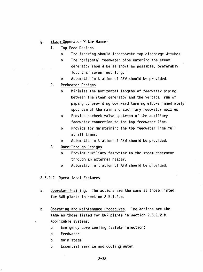
g. Steam Generator Water Hammer
1. Top Feed Designs
o The feedring should incorporate top discharge J-tubes.
o The horizontal feedwater pipe entering the steam
generator should be as short as possible, preferably
less than seven feet long.
o Automatic initiation of AFW should be provided.
2. Preheater Designs
o Minimize the horizontal lengths of feedwater piping
between the steam generator and the vertical run of
piping by providing downward turning elbows immediately
upstream of the main and auxiliary feedwater nozzles.
o Provide a check valve upstream of the auxiliary
feedwater connection to the top feedwater line.
o Provide for maintaining the top feedwater line full
at all times.
o Automatic initiation of AFW should be provided.
3. Once-Through Designs
o Provide auxiliary feedwater to the steam generator
through an external header.
o Automatic initiation of AFW should be provided.
2.5.2.2 Operational Features
a. Operator Training. The actions are the same as those listed
for BWR plants in section 2.5.1.2.a.
b. Operating and Maintenance Procedures. The actions are the
same as those listed for BWR plants in section 2.5.1.2.b.
Applicable systems:
o Emergency core cooling (safety injection)
o Feedwater
o Main steam
o Essential service and cooling water.
2-38
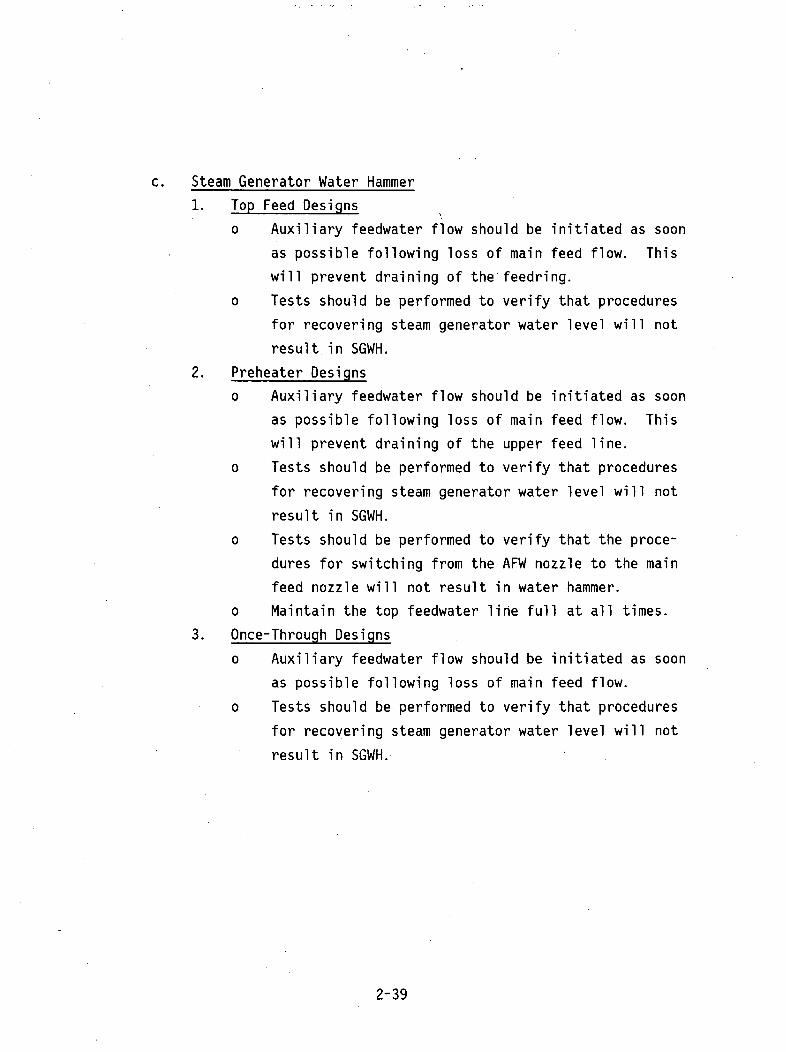
c. Steam Generator Water Hammer
1. Top Feed Designs
o Auxiliary feedwater flow should be initiated as soon
as possible following loss of main feed flow. Thiswill prevent draining of the feedring.
o Tests should be performed to verify that procedures
for recovering steam generator water level will not
result in SGWH.
2. Preheater Designs
o Auxiliary feedwater flow should be initiated as soon
as possible following loss of main feed flow. This
will prevent draining of the upper feed line.
o Tests should be performed to verify that procedures
for recovering steam generator water level will not
result in SGWH.
o Tests should be performed to verify that the proce-
dures for switching from the AFW nozzle to the main
feed nozzle will not result in water hammer.
o Maintain the top feedwater line full at all times.
3. Once-Through Designs
o Auxiliary feedwater flow should be initiated as soon
as possible following loss of main feed flow.
o Tests should be performed to verify that procedures
for recovering steam generator water level will not
result in SGWH.
2-39


3.0 WATER HAMMER PREVENTION AND MITIGATION MEASURES
Section 3.0 provides additional details concerning the measures for
water hammer prevention and mitigation contained in section 2.5.
Because these measures may be applied to more than one system, the
following generic subjects are identified:
o Void Detection Systems
o Keep Full Systems
o Venting
o Filling Safety-Related, Open-Loop Service Water Systems
o HPCI Turbine Inlet Line Valve
o Feedwater Control Valve and Controller
o HPCI and RCIC Turbine Exhaust Line Vacuum Breakers
o Steam Hammer
o Relief Valve Discharge
o HPCI Turbine Inlet Line Drain Pot Level Detection
o Operator Training
o Operating and Maintenance Procedures.
Water hammer assessments are generally performed during systems evalua-
tions rather than during generic evaluations. Therefore, a systematic
approach has been developed for using these findings. Table 3-1
summarizes for each BWR system the water hammer events that have
occurred in the system and lists both design and operational means for
water hammer prevention and mitigation. It is suggested that when
reviewing a BWR system for water hammer considerations, the reviewer
look up the system in table 3-1 to determine the appropriate review
considerations and and then review the topics presented in sections 3.1
through 3.11.
Table 3-2 presents similar information for PWR systems and should be
used in a similar manner to that described for BWR systems.
3-1

Tables 3-3 and 3-4 (for PWR and BWR) respectively identify which
operating and maintenance procedure considerations discussed in
section 3.12 are applicable to each plant system. Thus, for example,
table 3-3 shows that the operating and maintenance procedures for PWR
ECCS should address prevention of rapid valve motion, avoidance of voids
in water-filled lines and components, and proper filling and venting of
water-filled lines and components.
Finally, it should be noted that the findings set forth below represent
the results of over 10 years' accumulated experience, design changes,
etc., and therefore should benefit new designs.
3.1 Void Detection Systems
o A void detection system could be provided to detect voids at all
high points in liquid-filled normally idle piping, where voids or
steam bubbles could form through maintenance, operation, draining,
out-leakage, gas evolvement, or in-leakage of steam of flashing
fluid; and the potential for damaging water hammer events in
safety systems exist.
o The void detection system could provide detection at all high
points, including components and portions of lines isolated from
other high points by valves.
0 Void detection instrumentation can provide indication in the
control room or locally. If local indication is provided, it
should be demonstrated that radiation exposure to personnel will be
As Low As Reasonably Achievable (ALARA).
0 Void detection systems should be provided with means to test or
verify the operability of the system.
o Void detection system displays and controls, if added to the
control room, should not increase the potential for operator error.
A human factors analysis should be performed, as required, taking
into consideration the use of the information by an operator during
both normal and abnormal plant conditions.
3-2

o Portions of piping or components that can only become voided during
maintenance operations need not be continuously monitored, provided
design or procedural measures have been implemented which will
ensure that all voids will be eliminated prior to returning the
piping or components to service.
o Operating procedures should incorporate a requirement that any void
detected in the applicable systems (tables 3-1 and 3-2) shall be
corrected as sooon as practical.
3.2 Keep-Full Systems
o A keep-full system should be provided as to prevent void formation
in normally idle water-filled lines for the systems listed in
tables 3-1 and 3-2.
o The keep-full system should be designed to operate continuously.
An acceptable design is a continuously operating jockey pump or a
storage tank with a water level at a higher elevation than the
lines which it services.
0 The keep-full system should be adequately sized to meet head and
flow demands. The design of the keep-full system should account
for line elevation, friction, and any pressure increases induced by
valve in-leakage. The flow capacity of the keep-full system should
accommodate the combined maximum leak rate of all the systems it
services. Justifiable safety margins should be demonstrated in
establishing head and flow demand values.
o The keep-full system should have the capability to provide
detection of significant leakage in piping systems it services.
o Keep-full instrumentation should provide indication in the control
room or locally. If local indication is provided, it should be
demonstrated that radiation exposure to personnel will be As Low As
Reasonably Achieveable (ALARA).
o The keep-full system should be provided with means to test or
verify the operability of the system.
3-3

o The keep-full system displays and controls should not increase the
potential for operator error. A human factors analysis should be
performed, taking into consideration the use of the information by
an operator during both normal and off-normal plant conditions.
3.3 Venting
o Vents should be provided to vent components and piping at all
points specified in section 3.1.
o Vents in locations where voiding may occur during normal operation
should be automatic, remotely operated, or designed for easy access
and operator usage. Manual locally operated vents can be used for
those locations where voiding can occur only during maintenance
operations.
o Operating areas, where manual vents are located, shall be analyzed
to assure adequate human operator environmental conditions including
light, heat, access and radiation levels.
o The vent system design should provide the operator with the ability
to determine the adequacy of a venting operation.
0 The design and location of either remote or local controls for
nonautomatic vents should be such that radiation releases will be
As Low As Reasonably Achieveable (ALARA).
o The size of vent lines connected to the reactor coolant boundary
should be kept smaller than the size corresponding to the definition
of a LOCA (10 CFR part 50, appendix A) to avoid unnecessary chal-
lenges to the ECCS.
o Venting system displays and controls, if added to the control room,
should not increase the potential for operator error. A human
factors analysis should be performed, as required, taking into
consideration the use of the information by an operator during both
normal and abnormal plant conditions.
o Means should be provided to test or verify the operability of the
vent system on a regular schedule.
3-4
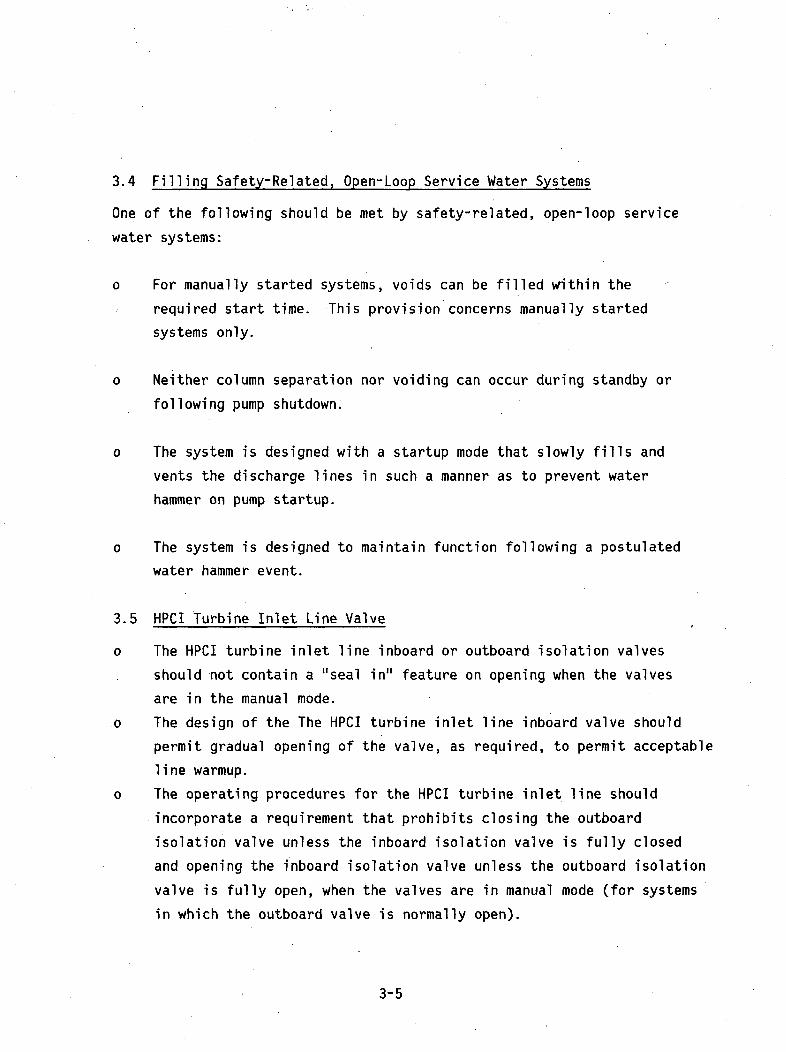
3.4 Filling Safety-Related, Open-Loop Service Water Systems
One of the following should be met by safety-related, open-loop service
water systems:
o For manually started systems, voids can be filled within the
required start time. This provision concerns manually started
systems only.
o Neither column separation nor voiding can occur during standby or
following pump shutdown.
o The system is designed with a startup mode that slowly fills and
vents the discharge lines in such a manner as to prevent water
hammer on pump startup.
o The system is designed to maintain function following a postulated
water hammer event.
3.5 HPCI Turbine Inlet Line Valve
o The HPCI turbine inlet line inboard or outboard isolation valves
should not contain a "seal in" feature on opening when the valves
are in the manual mode.
o The design of the The HPCI turbine inlet line inboard valve should
permit gradual opening of the valve, as required, to permit acceptable
line warmup.
o The operating procedures for the HPCI turbine inlet line should
incorporate a requirement that prohibits closing the outboard
isolation valve unless the inboard isolation valve is fully closed
and opening the inboard isolation valve unless the outboard isolation
valve is fully open, when the valves are in manual mode (for systems
in which the outboard valve is normally open).
3-5

3.6 Feedwater Control Valve and Controller
o The feedwater control valve design should be reviewed to verify
that the valve design parameters, including actuator, flow coeffi-
cient (CV), and trim, are compatible with all final-designed
operating conditions of the condensate and feedwater system.
Specifically, the following concerns should be addressed:
- The feedwater control valve calculated or actual pressure drop
should be compared with the valve specification to verify
valve compatibility for the entire operating range of the
valve.
- If low flow bypass valves are used, the feedwater bypass valve
and the feedwater control valve interaction should be reviewed
to ensure that the lower end of the feedwater controllable
operating range is below the level at which the low-flow
bypass valves are used in place of the feedwater control
valves.
- Feedwater control valve stroke versus load characteristics,
minimum steady-state operating loads, valve stability lower
limit ranges, and other information affecting valve stability
should be reviewed to verify that instability will not occur
at the least open-valve steady-state operating point.
- Values of the minimum static pressure in the feedwater control
valve, the vapor pressure of the fluid, and other information
affecting flashing should be reviewed to ensure that flashing
will not occur at steady-state or normal transient conditions.
- The sizing of the feedwater control valve should be compatible
with the remainder of the feedwater and condensate systems.
The valve should not be excessively oversized.
- Feedwater control valve testing or operating experience data
should be reviewed to verify that valve stroke characteristics
will provide stable operation.
3-6

- Feedwater control valve design should be reviewed to verify
that valve trim imbalance has been considered. Minimizing
imbalance generally tends to increase valve stability.
0 The feedwater controller valve control design should be reviewed to
verify that the design precludes rapid valve actuation motion under
any planned or spurious signal.
o The feedwater controller valve control design should be reviewed to
ensure that it has been designed to prevent excessive ocillations
and hunting.
0 Test, analytical, or operating experience data should be reviewed
to ascertain that neither valve nor control system components will
fail suddenly due to normal usage or fatigue, resulting in rapid
valve motion or flow rate changes.
3.7 HPCI and RCIC Turbine Exhaust Line Vacuum Breakers
o The HPCI and RCIC turbine exhaust lines should be provided with
vacuum breakers to prevent vacuum formation in any portion of the
exhaust line due to steam condensation.
0 The vacuum breaker design and location should be reviewed to deter-
mine that all requirements for the reactor coolant pressure boundary
are met.
0 The vacuum breaker design should be reviewed to determine that the
design precludes the introduction of water slugs from the suppression
pool and rapid check valve closure.
0 Vacuum breaker sizing should be reviewed to determine that the
design accounts for the effects of condensation caused by an unwarmed
exhaust line and water backflow.
3.8 HPCI Turbine Line Drain Pot Level Detection
o Drain systems should be provided for HPCI turbine lines to drain
all condensate from the line low spots.
3-7

o The HPCI turbine lines' configurations and slopes should be reviewed
to verify that all low spots drain to the drain system and that
sufficient slope is provided in the configuration to ensure
complete drainage.
0 HPCI line drain systems should be reviewed to verify that the drain
pots have been adequately sized to handle all expected condensate.
0 The HPCI turbine inlet line drain system should be reviewed to
verify that the design permits testing of the drain system with the
turbine inlet line isolation valves open.
0 HPCI turbine line drain systems should provide high-level
indication in the control room. The systems' displays and controls
should not increase the potential for operator error. A human
factors analysis should be performed, as required, taking into
consideration the use of the information by an operator during both
normal and abnormal plant conditions. Means should be provided to
test the operability of the HPCI line drain systems' level
indicators and bypass valves.
o The procedures for the HPCI system should incorporate a requirement
that the level indicators on the HPCI drain pot system should be
checked on a regular schedule for operability.
3.9 Steam Hammer
The design bases for the main steam components and pipe supports should
consider steam hammer forces resulting from the most rapid anticipated
closure of all system valves, including the turbine stop valves.
3.10 Relief Valve Discharge
The design basis for the components and pipe supports of the applicable
systems should consider fluid forces resulting from safety and relief
valve operation, including those loads from water slugs where water
seals are used or the valve lines normally contain subcooled or saturated
liquid.
3-8
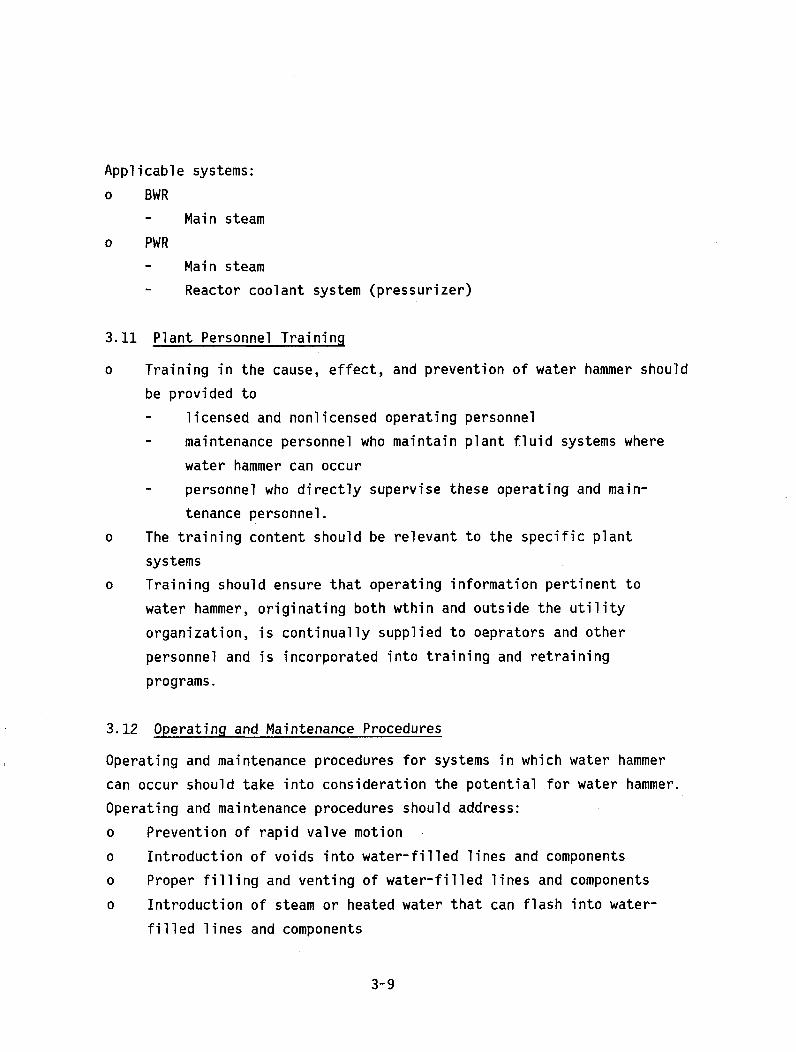
Applicable systems:
o BWR- Main steam
o PWR- Main steam
- Reactor coolant system (pressurizer)
3.11 Plant Personnel Training
o Training in the cause, effect, and prevention of water hammer should
be provided to- licensed and nonlicensed operating personnel
- maintenance personnel who maintain plant fluid systems where
water hammer can occur
- personnel who directly supervise these operating and main-
tenance personnel.
0 The training content should be relevant to the specific plant
systems
o Training should ensure that operating information pertinent to
water hammer, originating both wthin and outside the utility
organization, is continually supplied to oeprators and other
personnel and is incorporated into training and retraining
programs.
3.12 Operating and Maintenance Procedures
Operating and maintenance procedures for systems in which water hammer
can occur should take into consideration the potential for water hammer.
Operating and maintenance procedures should address:
o Prevention of rapid valve motion
o Introduction of voids into water-filled lines and components
o Proper filling and venting of water-filled lines and components
o Introduction of steam or heated water that can flash into water-
filled lines and components
3-9

o Introduction of water into steam-filled lines or components
o Proper warmup of steam-filled lines
o Proper drainage of steam-filled lines
o The effects of valve alignments on line conditions.
3.13 Steam Generator Water Hammer (SGWH)
The following provisions of Branch Technical Position ASB 10-2 (reference 3)
should be followed.
a. "Top Feed Designs
1. Prevent or delay water draining from the feedring following a
drop in steam generator water level by means such as J-tubes.
2. Minimize the volume of feedwater piping external to the steam
generator which could pocket steam using the shortest possible
(less than seven feet) horizontal run of inlet piping to the
steam generator feedring.
3. Perform tests acceptable to NRC to verify that unacceptable
feedwater hammer will not occur using the plant operating
procedures for normal and emergency restoration of steam
generator water level following loss of normal feedwater and
possible draining of the feedring. Provide the procedures for
these tests for approval before conducting the tests.
b. Preheater Designs
1. Perform tests acceptable to NRC to verify that unacceptable
feedwater hammer will not occur using plant operating procedures
for normal and emergency restoration of steam generator water
level following loss of normal feedwater. Also perform a
water hammer test at *% of power by using feedwater through
the auxiliary feedwater (top) nozzle at the lowest feedwater
*The power level at which feedwater flow is transferred from the auxiliary
feedwater nozzle to the main feedwater nozzle.
3-10

temperature that the plant standard operating procedure (SOP)
allows and then switching the feedwater at that temperature
from the auxiliary feedwater nozzle to the main feedwater
(bottom) nozzle by following the SOP.
2. Minimize the horizontal lengths of feedwater piping between
the steam generator and the vertical run of piping by providing
downward turning elbows immediately upstream of the main and
auxiliary feedwater nozzles.
3. Provide a check valve upstream of the auxiliary feedwater
connection to the top feedwater line.
4. Maintain the top feedwater line full at all times.
C. Once-Through Designs (B&W)
1. Provide auxiliary feedwater to the steam generator through an
external header.
2. Perform tests acceptable to NRC to verify that unacceptable
feedwater hammer will not occur using the plant operating
procedures for normal and emergency restoration of steam
generator water level following loss of normal feedwater.
Provide the procedures for these tests for approval before
conducting the tests."
d. NUREG 0737, paragraph II.E.1.2 (reference 15), requires automatic
auxiliary feedwater system initiation. The requirements for the
AFW system automatic initiation are contained in reference 15.
3.14 Control Rod Drive (CRD) Hydraulic Lines
The design basis for CRD hydraulic lines should consider the tran-
sient forces resulting from the worst case CRD system actuation.
3-11

TABLE 3-1. BWR System Water Hammer Causes and Preventive Measures.
SYSTEM PRIMARY CAUSES PREVENTIVE MEASURES (*)OF WATER HAMMER DESIGN PLANT OPERATION
RHR Voiding, Steam- Void Detection Void Detection and Cor-Bubble Collapse (3.1), rection (3.1), Venting
Keep-full (3.2), (3.2), Operating Proce-Venting, (3.3) dures (3.12), Operator
Training (3.11)
HPCI Steam Water Entrain- No Opening Seal-in Valve Opening Sequencement, Turbine Inlet in Manual Mode (3.5c), Operator Train-Valve Operation (3.5a), Gradual ing (3.11), Operating
Opening (3.5b) Procedures (3.12)
Steam Water Entrain- Proper Drain Verification of Drainment Drain Pot System Including Pot Level (3.8), Operat-Malfunction Drain Pot Sizing ing Procedures (3.12)
and Level Verifi-cation (3.8)
Turbine Exhaust Line Exhaust Line VacuumBubble Collapse Vacuum Breakers
Pump Discharge Line Void Detection Void Detection andVoiding (3.1), Keep-Full Correction (3.1), Vent-
System (3.2), ing (3.2), OperatingVenting (3.3) Procedures (3.12),
Operator Training (3.11)
Core Voiding Steam- Void Detection Void Detection and Cor-Spray Bubble Collapse (3.1), Keep-Full rection (3.1), Venting
System (3.2), (3.2), Operating Proce-Venting (3.3) dures (3.12), Operator
Training (3.11)
Essen- Voiding Column Void Detection Void Detection and Cor-tial Separation (3.1), Keep-Full rection (3.1), VentingService System (3.2), (3.2), Operating Pro-Water Venting (3.3), cedures (3.12), Operator
Open Loop Line Training (3.11)Analysis (3.4)
(*)Refers to section of this report providing details of preventive measures.
3-12

TABLE 3-1. Continued
SYSTEM PRIMARY CAUSES PREVENTIVE MEASURESOF WATER HAMMER DESIGN PLANT OPERATION
Main Steam Hammer Relief Valve Closure (3.9)Steam Valve Discharge and Relief Valve Dis-
charge Loads (3.10)
Steam Water Operating ProceduresEntrainment (3.12), Operator Train-
ing (3.11)
Feed- Feedwater Control Feedwater Controllerwater Valve Instability Design Verification
3.6a, b, and c
RCIC Exhaust Line Steam Exhaust Line VacuumBubble Collapse Breakers (3.7)
Isola- High Reactor Water Operating Procedurestion Level (3.12), Operator Train-Con- ing (3.11)denser
**Control Rapid Valve Actuation Loads
Rod motion (3.14)Drive
**Control Rod Drive events have not been reported, but have been anlytically
postulated.
3-13

TABLE 3-2. PWR System Water Hammer Causes and Preventive Measures.
SYSTEM PRIMARY CAUSES PREVENTIVE MEASURES (*)OF WATER HAMMER DESIGN PLANT OPERATION
Feed- Feedwater Control FCV Design Veri-water Valve (FCV) Over- fication (3.6)
sizing & Instability
Unknown and Operator Operating ProceduresError Induced Steam (3.12),.OperatorBubble Collapse Training (3.11)
Main Steam Hammer (Valve Include ValveSteam Closure) Closure Loads in
Pipe Support andComponent DesignBasis (3.9)
Relief Valve Include ReliefDischarge Valve Discharge
Loads in Pipe Sup-port and ComponentsDesign Basis (3.10)
Steam Water.Entrain- Operating Proceduresment, Unknown. (3.12), Operator Train-
ing (3.11)
Reactor. Relief Valve Include Relief ValveCoolant Discharge Discharge Loads in
.(Pres- Pipe Support andsurizer) Components Design
Basis (3.10)
RHR Voiding Venting (3.3) Operating Procedures(3.12), OperatorTraining (3.11)
E.CCS Voiding Venting (3.3), Operating ProceduresVoid Detection(3.1) (3.12), Operator
Training (3.11)
CVCS Steam Bubble Col- Operating Procedureslapse or Vibration (3.12), Operator
Training (3.11)
3-14

TABLE 3-2. Continued
SYSTEM PRIMARY CAUSES PREVENTIVE MEASURES (*)OF WATER HAMMER DESIGN PLANT OPERATION
Essen- Voiding Venting (3.1), Filling Essential Cool-tial Filling Essential ing Water (3.4), Oper-Cooling Cooling Water ating Procedures (3.12),Water (3.4), Analysis Operator Training
(3.4) (3.11)
Steam Line Voiding BTP ASB 10-2 BTP ASB 10-2 ProvisionsGener- Followed by Steam Provisions (3.13): (3.13): Testing, Keep-ator Bubble Collapse Top Discharge, ing Line Full. Auto-
Short Line matic AFW InitiationLengths, ExternalHeader (B&W Only)
(*)Refers to section of this report providing details of preventive measures.
3-15
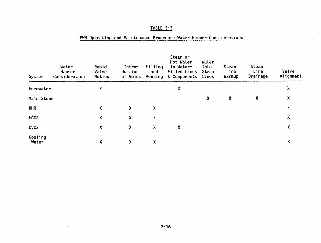
TABLE 3-3
PWR Operating and Maintenance Procedure Water Hammer Considerations
WaterHammer
System Consideration
RapidValveMotion
Intro-ductionof Voids
Fillingand
Venting
Steam orHot Waterin Water-
Filled Lines& Components
WaterIntoSteamLines
SteamLine
Warmup
SteamLine
DrainageValve
Alignment
Feedwater
Main Steam
RHR
ECCS
CVCS
CoolingWater
x xx x x
x
xx
x
x
xx
x
x
xx
x
x
xxxx
x
x
3-16
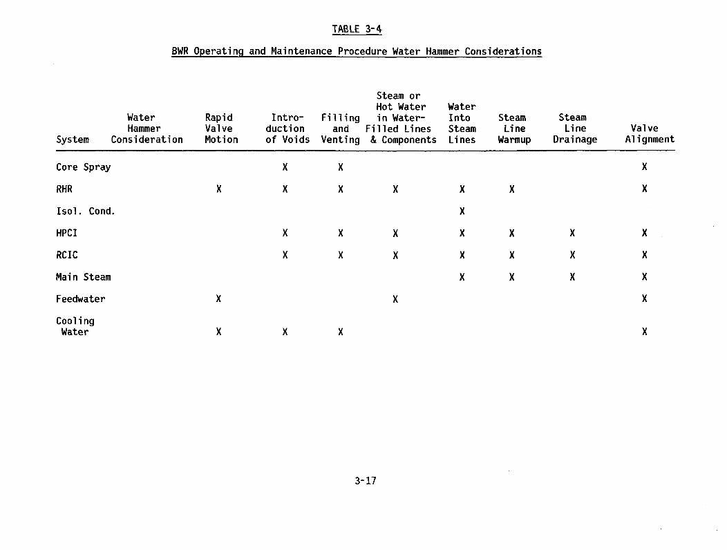
TABLE 3-4
BWR Operating and Maintenance Procedure Water Hammer Considerations
WaterHammer
System Consideration
RapidValveMotion
Intro-ductionof Voids
Fi liingand
Venting
Steam orHot Waterin Water-
Filled Lines& Components
WaterIntoSteamLines
SteamLine
Warmup
SteamLine
DrainageValve
Alignment
Core Spray
RHR
Isol. Cond.
HPCI
RCIC
Main Steam
Feedwater
CoolingWater
x
x
x
x
x
xx x
x
x
x
x
x
x
x
xxxx
x
x
xx
x
xx
x
xxx
x
x
x
x
x x
3-17

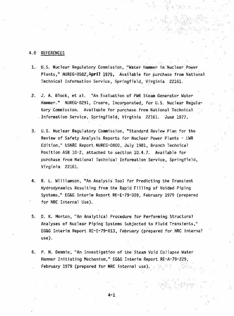
4.0 REFERENCES
1. U..S. Nuclear Regulatory Commission, ."Water Hammer in Nuclear Power
Plants," NUREG-0582,Apri-I 1979. Available for purchase from National
Technical Information Service, Springfield, Virginia 22161.
2. J. A. Block, et al. "An Evaluation of PWR Steam Generator. Water
Hammer." NUREG-0291, Creare,,Incorporated, for U..S. Nuclear Regula-
tory Commission. Available for purchase from National Technical
Information Service, Springfield, Virginia 22161. June 1977.
3. U.S. Nuclear Regulatory Commission, "Standard Review Plan for the
Review of Safety Analysis Reports for Nuclear Power Plants - LWR
Edition," USNRC Report NUREG-0800, July 1981, Branch Technical
Position ASB 10-2, attached to section 10.4.7. Available for
purchase from National Technical Information Service, Springfield,
Virginia 22161.
4. R. L. Williamson, "An Analysis Tool for Predicting the Transient
Hydrodynamics Resulting from the Rapid Filling of Voided Piping
Systems," EG&G Interim Report RE-E-79-009, February 1979 (prepared
for NRC Internal Use).
5. D. K. Morton, "An Analytical Procedure for Performing Structural
Analyses of Nuclear Piping Systems Subjected to Fluid Transients,"
EG&G Interim Report RE-E-79-013, February (prepared for.NRC internal
use).
6. P. N. Demmie, "An Investigation of the Steam Void Collapse Water
Hammer Initiating Mechanism," EG&G Interim Report RE-A-79-229,
February 1979 (prepared for NRC internal use).
4-1.

7. R. A. Berry, "An Analysis Tool for Predicting Transient Hydro-
dynamics in Nuclear Piping Systems Containing Swing Check Valves,"
EG&G Interim Report RE-A-78-261 (revision 2), September 1979
(prepared for NRC internal use).
8. R. L. Chapman et al., "Compilation of Data Concerning Known and
Suspected Water Hammer Events in Nuclear Power Plants," NUREG/CR-2059,
CAAD-5629, EG&G, Idaho, Incorporated. May 1982. Available for
purchase from National Technical Information Service, Springfield,
Virginia 22161.
9. R. A. Uffer, et al., "Evaluation of Water Hammer Events in Light
Water Reactor Plants," NUREG/CR-2781, QUAD-1-82-018, Quadrex Corpor-
ation, July 1982. Available for purchase from National Technical
Information Service, Springfield, Virginia 22161.
10. J. T. Han, and N. Anderson, "Prevention and Mitigation of Steam
Generator Water Hammer in PWR Plants," NUREG-0918, U.S. Nuclear
Regulatory Commission, November 1982. Available for purchase from
National Technical Information Service, Springfield, Virginia 22161.
11. P. Saha, et al., "An Evaluation of Condensation-Induced Water
Hammer in Preheat Steam Generators," NUREG/CR-1606, Brookhaven
National Laboratory, September 1980. Available for purchase from
National Technical Information Service, Springfield, Virginia 22161.
12. "Nuclear Power Plant Components," ASME Boiler and Pressure Vessel
Code, section III. Available from American Society of Mechanical
Engineers, New York, New York.
13. "American National Standard Code for Pressure Piping, Power Piping,"
ANSI/ASME B31.1, 1980 edition. Available from American Society of
Mechanical Engineers, New York, New York.
4-2

14. U.S. Nuclear Regulatory Commission, "Standard Review Plan for the
Review of Safety Analysis Reports for Nuclear Power Plants - LWR
Edition," USNRC Report NUREG-0800, July 1981, section 3.9.3 "ASME
Code Class 1, 2 and 3 Components, Component Supports, and Core
Support Structures." Available for purchase from National Tech-
nical Information Service, Springfield, Virginia 22161.
15. U.S. Nuclear Regulatory Commission, "Clarification of TMI Action
Plan Requirements," NUREG-0737, November 1980, paragraphs II.D.1
and II.E.l.2. Available for purchase from National Technical
Information Service, Springfield, Virginia 22161.
16. D. E. Sexton, M. Kasahara and R. A. Uffer, "Evaluation of Water
Hammer Potential in Preheat Steam Generators," NUREG/CR-3090,
QUAD-1-82-243, Quadrex Corporation, January 1983. Available for
purchase from National Technical Information Service, Springfield,
Virginia 22161.
17. Letter to A. W. Serkiz, U.S. NRC, from F. R. Seddiqui, Reactor
Controls, Inc. dated July 29, 1983.
4-3


NRC FORM 335 usNU1. REPORT NUMBER (Assigned by DDCJSU.S. NUCLEAR REGULATORY COMMISSION NUREG- O927PRev. I
BIBLIOGRAPHIC DATA SHEET4. TITLE AND SUBTITLE (Add Volume No., if appropriate) 2. (Leave blank)
Evaluation of Water Hammer Occurrence in Nuclear Power 3. RECIPIENT'S ACCESSION NO.
Plants, Technical Findings Relevant to USI A-17. AUTHOR(S) 5. DATE REPORT COMPLETED
A. W. Serkiz M ecember Inn9. PERFORMING ORGANIZATION NAME AND MAILING ADDRESS (Include Zip Code) DATE REPORT ISSUED
Division of Safety Technology MONTH
office of Nuclear Reactor Regulation MarchU.S. Nuclear Regulatory Commission 6. (Leave blank)
Washington, DC 20555 6. ( _eave blank)B. (Leave blank)
•..SP.ON.SORIN• O~1GANIZAT.LON NAM.,E AND MAILING ADDRESS (Include Zip Code)'division O aeyecnnoliogy 10. PROJECT/TASK/WORK UNIT NO.
Office of Nuclear Reactor Regulation TACS #04469U.S. Nuclear Regulatory Commission 11. FIN NO.Washington, DC 20555
13. TYPE OF REPORT PERIOD COVERED (Inclusive dates)
Final
15. SUPPLEMENTARY NOTES 14. (Leave blank)
16. ABSTRACT (200 words or less)
This report, which includes responses to public comments, summarizes key technical findingsrelevant to the Unresolved Safety Issue A-i, Water Hammer. These findings were derived fromstudies of reported water hammer occurrences and underlying causes and provide key insightsinto means to minimize or eliminate further water hammer occurrences. It should also benoted that this report does not represent a substitute for current rules and regulations.
17. KEY WORDS AND DOCUMENT ANALYSIS 17a. DESCRIPTORS
USI A-iWater Hammer in Nuclear Power PlantsTechnical Findings for USI A-i
17b, IDENTIFIERS/OPEN-ENDED TERMS
18. AVAILABILITY STATEMENT 19. SCUR TY CIASS (This report) 21. NO. OF PAGESunciassifieoUnlimited 20. SECURITY CLASS (This page) 22. PRICE
IUnclasgifiPd SNRC FORM 335 (11-811
* U.S. GOVERNMENT PRINTING OFFICE: 1984-421-297:3829


UNITED STATES
NUCLEAR REGULATORY COMMISSION
WASHINGTON, D.C. 20555
FOU RTH-C(ASS MAIL
POSTAGE & FEES PAIDUSNRC
WASH. 0. C.PE:RMIT No _jjl
OFFICIAL BUSINESSPENALTY FOR PRIVATE USE, $300
N,,'"
N LI
1' 0
- ' 'V. -
) I
On
a-