evaluation of vehicle emissions reduction options for … sands retrofit... · evaluation of...
TRANSCRIPT
EVALUATION OF VEHICLE
EMISSIONS REDUCTION OPTIONS FOR THE OIL SANDS
MINING FLEET
FINAL REPORT March, 2008
Submitted to:
Oil, Gas & Alternative Energy Division 20th Floor, PVM 351 St Joseph Blvd Hull, Quebec KIA 0H3 Attention: Mark Tushingham
Submitted by:
M.J. Bradley & Associates 1000 Elm Street, 2nd Floor Manchester, NH 03101 (603) 647-5746


Emissions Reduction Options for Oil Sands Mining Fleet
M.J. Bradley & Associates i March 2008
Table of Contents
Executive Summary ................................................................................................................................ 1
1. Background – Oil Sands Sector....................................................................................................... 3
1.1 Oil Sands Mining Operations..........................................................................................3
1.2 Projected Vehicle Emissions from Mining Trucks .........................................................5
2. Mining Equipment Emissions Reduction Options .......................................................................... 8
2.1 Retrofit Options ..............................................................................................................8
2.1.1 Diesel Oxidation Catalyst (DOC)...................................................................................... 9
2.1.2 Passive Diesel Particulate Filter (P-DPF)........................................................................ 11
2.1.3 Active Diesel Particulate Filter (A-DPF) ........................................................................ 14
2.1.4 Selective Catalytic Reduction (SCR)............................................................................... 17
2.1.5 NOx Reduction Catalyst (NRC) ...................................................................................... 20
2.1.6 Exhaust Gas Recirculation (EGR) ................................................................................... 22
2.2 Engine Replacement/Upgrade Options.........................................................................26
2.2.1 Tier 0/1 – Tier 2 Upgrade/Repower................................................................................. 26
2.2.2 Tier 2 – Tier 4 Repower .................................................................................................. 27
3. Recommendations – Large Mining Trucks ................................................................................... 29
3.1 Mining Truck Emissions Retrofit/Upgrade Scenarios ..................................................29
3.2 Potential Emissions Reductions ....................................................................................31
3.3 Cost of Emissions Reductions ......................................................................................32
4. Recommended Additional Research ............................................................................................. 35
5. Research Methodology for This Report ........................................................................................ 35

Emissions Reduction Options for Oil Sands Mining Fleet
M.J. Bradley & Associates ii March 2008
List of Tables
Table 1.1 Examples of Commercially Available Non-road Haul Trucks
Table 1.2 Emission Standards for Non-road Diesel Engines Greater than 750 hp (564 kW)
Table 2.1 Diesel Engines Used in 218 – 363 tonne Mining Trucks
Table 2.2 Summary of PM Reduction Retrofit Technologies
Table 2.3 Summary of NOx Reduction Retrofit Technologies
Table 3.1 Mining Truck Emissions Reduction Scenarios
Table 3.2 Assumptions Used in Cost Calculations – Emissions Reduction Scenarios
Table 3.3 Cost of Emissions Reduction Scenarios – Oil Sands Mining Trucks
Table 3.4 Cost Effectiveness Ranges For Oil Sands Trucks Compared to EPA Estimates
List of Figures Figure ES-1 Potential Reductions in NOx and PM emissions from Oil Sands Mining Fleet
Figure 1.1 Alberta Oil Sands Areas
Figure 1.2 Large Mining Trucks
Figure 1.3 Projected Oil Sands Mining Truck Fleet, 2007 - 2035
Figure 1.4 Projected Annual NOx Emissions From the Oil Sands Mining Truck Fleet
Figure 1.5 Projected Annual PM Emissions From the Oil Sands Mining Truck Fleet
Figure 2.1 Typical Diesel Oxidation Catalyst
Figure 2.2 CRT ™ Passive Diesel Particulate Filter for an On-road Truck <500 hp
Figure 2.3 MobiClean ™ Active Diesel Particulate Filter with Fuel Burner
Figure 2.4 Schematic of Argillon SINOx™ SCR System for Stationary Engines
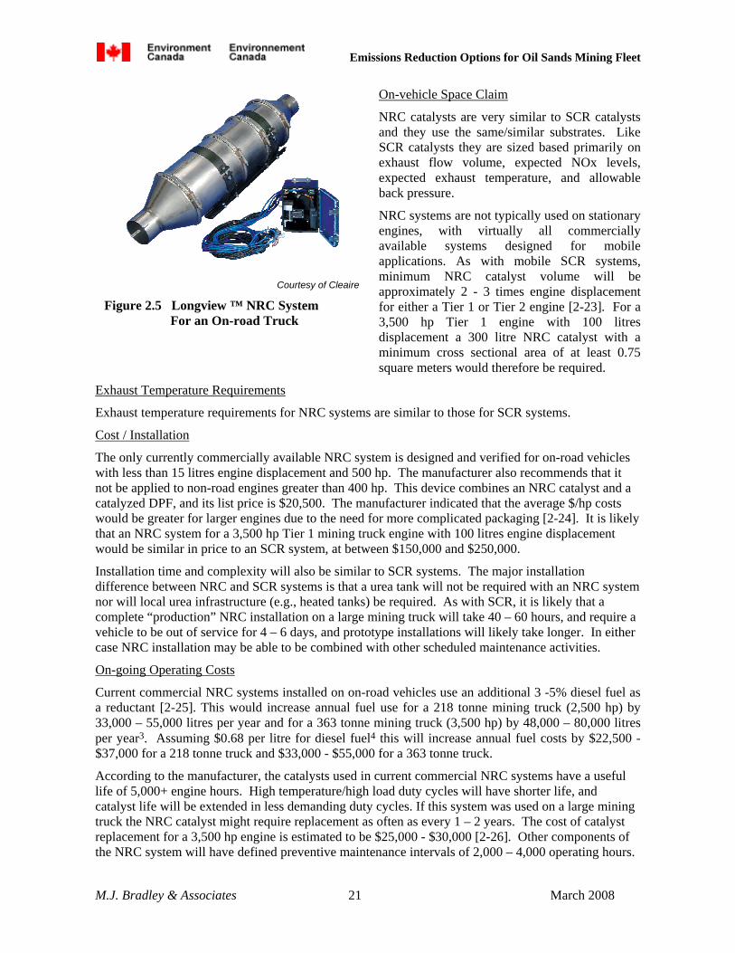
Figure 2.5 Longview ™ NRC System For an On-road Truck
Figure 2.6 EGRT ™ Low Pressure EGR System for On-road Truck
Figure 3.1 Potential Reductions in NOx Emissions from the Oil Sands Mining Truck Fleet
Figure 3.2 Potential Reductions in PM Emissions from the Oil Sands Mining Truck Fleet
Emissions Reduction Options for Oil Sands Mining Fleet
M.J. Bradley & Associates 1 March 2008
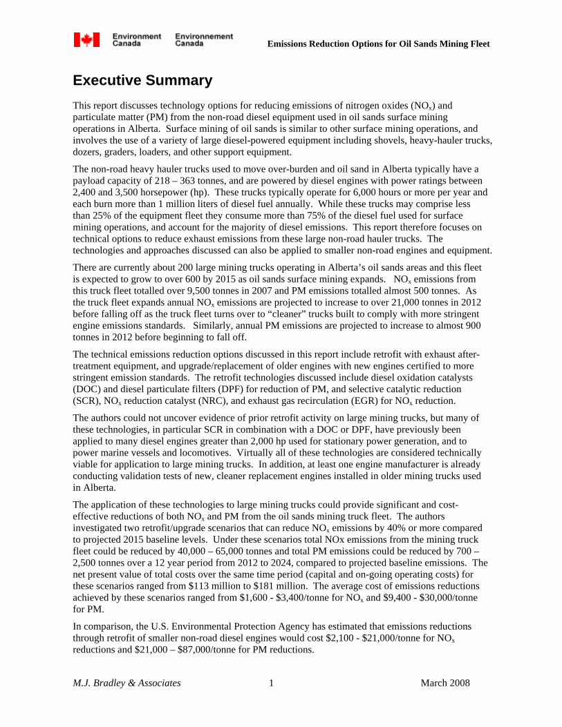
Executive Summary This report discusses technology options for reducing emissions of nitrogen oxides (NOx) and particulate matter (PM) from the non-road diesel equipment used in oil sands surface mining operations in Alberta. Surface mining of oil sands is similar to other surface mining operations, and involves the use of a variety of large diesel-powered equipment including shovels, heavy-hauler trucks, dozers, graders, loaders, and other support equipment.
The non-road heavy hauler trucks used to move over-burden and oil sand in Alberta typically have a payload capacity of 218 – 363 tonnes, and are powered by diesel engines with power ratings between 2,400 and 3,500 horsepower (hp). These trucks typically operate for 6,000 hours or more per year and each burn more than 1 million liters of diesel fuel annually. While these trucks may comprise less than 25% of the equipment fleet they consume more than 75% of the diesel fuel used for surface mining operations, and account for the majority of diesel emissions. This report therefore focuses on technical options to reduce exhaust emissions from these large non-road hauler trucks. The technologies and approaches discussed can also be applied to smaller non-road engines and equipment.
There are currently about 200 large mining trucks operating in Alberta’s oil sands areas and this fleet is expected to grow to over 600 by 2015 as oil sands surface mining expands. NOx emissions from this truck fleet totalled over 9,500 tonnes in 2007 and PM emissions totalled almost 500 tonnes. As the truck fleet expands annual NOx emissions are projected to increase to over 21,000 tonnes in 2012 before falling off as the truck fleet turns over to “cleaner” trucks built to comply with more stringent engine emissions standards. Similarly, annual PM emissions are projected to increase to almost 900 tonnes in 2012 before beginning to fall off.
The technical emissions reduction options discussed in this report include retrofit with exhaust after-treatment equipment, and upgrade/replacement of older engines with new engines certified to more stringent emission standards. The retrofit technologies discussed include diesel oxidation catalysts (DOC) and diesel particulate filters (DPF) for reduction of PM, and selective catalytic reduction (SCR), NOx reduction catalyst (NRC), and exhaust gas recirculation (EGR) for NOx reduction.
The authors could not uncover evidence of prior retrofit activity on large mining trucks, but many of these technologies, in particular SCR in combination with a DOC or DPF, have previously been applied to many diesel engines greater than 2,000 hp used for stationary power generation, and to power marine vessels and locomotives. Virtually all of these technologies are considered technically viable for application to large mining trucks. In addition, at least one engine manufacturer is already conducting validation tests of new, cleaner replacement engines installed in older mining trucks used in Alberta.
The application of these technologies to large mining trucks could provide significant and cost-effective reductions of both NOx and PM from the oil sands mining truck fleet. The authors investigated two retrofit/upgrade scenarios that can reduce NOx emissions by 40% or more compared to projected 2015 baseline levels. Under these scenarios total NOx emissions from the mining truck fleet could be reduced by 40,000 – 65,000 tonnes and total PM emissions could be reduced by 700 – 2,500 tonnes over a 12 year period from 2012 to 2024, compared to projected baseline emissions. The net present value of total costs over the same time period (capital and on-going operating costs) for these scenarios ranged from $113 million to $181 million. The average cost of emissions reductions achieved by these scenarios ranged from $1,600 - $3,400/tonne for NOx and $9,400 - $30,000/tonne for PM.
In comparison, the U.S. Environmental Protection Agency has estimated that emissions reductions through retrofit of smaller non-road diesel engines would cost $2,100 - $21,000/tonne for NOx reductions and $21,000 – $87,000/tonne for PM reductions.

Emissions Reduction Options for Oil Sands Mining Fleet
M.J. Bradley & Associates 2 March 2008
See Figure ES-1 which shows potential reductions in NOx and PM emissions from the emissions upgrade scenarios investigated in this report.
Oil Sands Mining Truck Annual NOx Emissions - Potential Reductions
-
5,000
10,000
15,000
20,000
25,000
2005 2010 2015 2020 2025 2030 2035
Ann
ual T
onne
s
BASE CASE
TARGET
40% REDUCTIONFROM 2015 BASELINE
Scenario 1(REPOWER)
Scenario 2 (SCR RETROFIT)
Oil Sands Mining Truck Annual PM Emissions - Potential Reductions
0
200
400
600
800
1000
2005 2010 2015 2020 2025 2030 2035
Ann
ual T
onne
s
BASE CASE
Scenario 1(REPOWER)
Scenario 2a (DOC RETROFIT)
Scenario 2b (DPF RETROFIT)
Figure ES-1 Potential Reductions in NOx and PM emissions from Oil Sands Mining Fleet

Emissions Reduction Options for Oil Sands Mining Fleet
M.J. Bradley & Associates 3 March 2008
1. Background – Oil Sands Sector The term “Oil Sands” refers to deposits of sand saturated with bitumen, which is a naturally occurring, viscous mixture of heavy hydrocarbons. After recovery bitumen can be “upgraded” to synthetic crude oil via distillation, thermal conversion, catalytic conversion, and hydrotreating [1-1]. The synthetic crude oil can then be refined into common petroleum products such as gasoline and diesel fuel in a standard refinery.
The province of Alberta contains three major oil sands areas that encompass approximately 80,000 square kilometres: the Athabasca, Cold Lake, and Peace River areas. The bitumen content in typical Alberta oil sand deposits ranges from 1% to 18%. More than 12% is considered rich, while less than 6% is generally considered too poor to be economically feasible for mining [1-2]. On average it takes two tonnes of mined oil sand to make one barrel (159 litres) of synthetic crude oil [1-2]. The oil sands deposits in Alberta are estimated to contain 1.7 – 2.5 trillion barrels of bitumen [1-3].
Bitumen cannot be extracted from the ground via wells like conventional crude oil. Approximately 20% of Alberta’s oil sand deposits are close enough to the surface that they can be mined with surface mining techniques and are concentrated in the Athabasca region near the town of Fort McMurray. The remainder are so deep that surface mining is cost prohibitive. In these deep deposits the bitumen must be extracted using in-situ techniques [1-2].
The first large-scale commercial oil sands surface mining operation in Alberta opened in 1967 and today there are three in operation (Suncor Energy, Syncrude Canada, and Albian Sands). Eight additional surface mines are under development and expected to start
producing by 2013 [1-4]. See Figure 1.1 for a map of Alberta’s oil sands areas.
This report deals with emissions reduction options for the large mining equipment used in oil sands surface mining operations.
1.1 Oil Sands Mining Operations Oil sands surface mining is similar to other surface mining operations, for example coal mining. Surface mining involves removing and storing the over burden (muskeg and layers of soil) to expose the oil sand deposit, then extracting the oil sand and transporting it to an on-site plant for initial processing to separate the bitumen from the sand. Historically, various equipment has been used to extract and transport the mined oil sand, including bucket wheel excavators, conveyor belts, and drag lines.
Today virtually all surface mining of oil sands in Alberta is done using truck and shovel [1-5].
Figure 1.1 Alberta Oil Sands Areas
Emissions Reduction Options for Oil Sands Mining Fleet
M.J. Bradley & Associates 4 March 2008
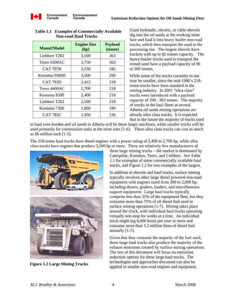
Giant hydraulic, electric, or cable shovels dig into the oil sands at the working mine face and load it into heavy hauler non-road trucks, which then transport the sand to the processing site. The largest shovels have buckets with up to 82 tonnes capacity. The heavy-hauler trucks used to transport the mined sand have a payload capacity of 90 to 360 tonnes.
While some of the trucks currently in use may be smaller, since the mid-1980’s 218-tonne trucks have been standard in the mining industry. In 2001 “ultra class” trucks were introduced with a payload capacity of 290 - 363 tonnes. The majority of trucks in the haul fleets at several Alberta oil sands mining operations are already ultra class trucks. It is expected that in the future the majority of trucks used
to haul over-burden and oil sands in Alberta will be these larger machines, while smaller trucks will be used primarily for construction tasks at the mine sites [1-6]. These ultra class trucks can cost as much as $6 million each [1-5].
The 218-tonne haul trucks have diesel engines with a power rating of 2,400 to 2,700 hp, while ultra class trucks have engines that produce 3,500 hp or more. There are relatively few manufacturers of
these large mining trucks – the market is dominated by Caterpillar, Komatsu, Terex, and Liebherr. See Table 1.1 for examples of some commercially available haul trucks, and Figure 1.2 for two examples of the largest.
In addition to shovels and haul trucks, surface mining typically involves other large diesel powered non-road equipment with engines sized from 300 to 2,000 hp, including dozers, graders, loaders, and miscellaneous support equipment. Large haul trucks typically comprise less than 25% of the equipment fleet, but they consume more than 75% of all diesel fuel used in surface mining operations [1-7]. Mining takes place around the clock, with individual haul trucks operating virtually non-stop for weeks at a time. An individual truck might log 6,000 hours per year or more and consume more than 1.2 million litres of diesel fuel annually [1-7].
Given that they consume the majority of the fuel used, these large haul trucks also produce the majority of the exhaust emissions created by surface mining operations. The rest of this document will focus on emissions reduction options for these large haul trucks. The technologies and approaches discussed can also be applied to smaller non-road engines and equipment.
Table 1.1 Examples of Commercially Available Non-road Haul Trucks
Manuf/Model Engine Size
(hp) Payload (tonne)
Liebherr T282 3,500 363 Terex 6300AC 3,750 363
CAT 797B 3,550 345 Komatsu 930SE 3,500 290
CAT 793D 2,415 218 Terex 4400AC 2,700 218 Komatsu 830E 2,400 218 Liebherr T262 2,500 218 Komatsu 730E 1,860 180
CAT 785C 1,450 136
Figure 1.2 Large Mining Trucks

Emissions Reduction Options for Oil Sands Mining Fleet
M.J. Bradley & Associates 5 March 2008
1.2 Projected Vehicle Emissions from Mining Trucks A discussion of how exhaust emissions from new non-road engines are regulated in Canada must focus on regulations promulgated by the U.S. Environmental Protection Agency (U.S. EPA) because Environment Canada has adopted EPA’s emission standards for new non-road engines greater than 750 hp (564 kW).
Prior to the 2000 model year, emissions levels from non-road diesel engines greater than 750 hp (564 kW) were unregulated (Tier 0). Beginning with the 2000 model year the U.S. EPA promulgated “Tier 1” standards, which for the first time specified maximum emissions levels from new non-road engines. Allowable emissions levels from new non-road engines were tightened with U.S. EPA’s Tier 2 standards beginning in the 2006 model year. U.S. EPA skipped Tier 3 for these large engines and adopted interim Tier 4 emissions standards which will require further reductions in emissions of nitrogen oxides (NOx) and particulate matter (PM) beginning in the 2011 model year. Beginning in the 2015 model year the final Tier 4 standards will lower allowable PM emissions yet again, while leaving allowable NOx at the same level (see Table 1.2).
Compared to a Tier 1 engine a Tier 2 engine will have 30% lower NOx and 60% lower PM emissions, while a Tier 4 engine will have 60% lower NOx and 90% lower PM.
There are currently over 200 large mining trucks operating in Alberta’s oil sands areas, and this fleet is expected to grow to over 600 by 2015 [1-8]. Many of the current trucks in use are probably unregulated, while some will have engines compliant with Tier 1 emissions regulations.
Most of the projected fleet growth over the next few years will be vehicles with engines
certified to Tier 2 emission standards. In addition, some existing unregulated and Tier 1 trucks will likely be replaced with Tier 2 trucks based on normal fleet turnover. Based on an assumed useful life of 12 years1, it will be 2028 or later before the entire fleet turns over to “clean” trucks certified to meet Tier 4 emission standards (see Figure 1.3).
This fleet of trucks is a significant emissions source in the oil sands areas. Assuming that each truck operates for 6,000 hours per year and consumes on average 246 litres per hour of diesel fuel2, annual NOx emissions from the fleet totalled over 9,500 tonnes in 2007, while annual PM emissions totalled 498 tonnes.
1 Per M. Tushingham, Environment Canada. Based on testimony by Shell Canada at the environmental hearing for the Muskeg River mine expansion (2006) .
2 This assumes that 25% of the fleet is composed of 218 tonne trucks that consume approximately 186 litres/hour of fuel and 75% of the fleet is composed of 350 tonne trucks that consume approximately 266 litres/hour of fuel. For both truck types this equates to an average engine load of approximately 40% over a day’s operation, consistent with data provided in an Environmental Assessment filing for the Northern Lights mine and by Finning Caterpillar of Alberta.
Table 1.2 Emission Standards for Non-road Diesel Engines > 750 hp (564 kW)
g/kWh Standard Model
Year NOx PM
Tier 1 2000 9.20 0.54
Tier 2 2006 6.40 0.20
Tier 4i 2011 3.50 0.10
Tier 4 2015 3.50 0.04

Emissions Reduction Options for Oil Sands Mining Fleet
M.J. Bradley & Associates 6 March 2008
Based on projected truck fleet growth, NOx emissions from these mining trucks are expected to increase to over 21,000 tonnes in 2012, before falling off based on fleet turnover to cleaner Tier 4 trucks. After 2026 they are expected to stabilize at approximately 12,500 tonnes annually, 31% higher than they are today (see Figure 1.4)3.
At the same time, annual PM emissions are expected to increase to approximately 879 tonnes in 2012 before beginning to fall off. Once the entire fleet has turned over to cleaner Tier 4 trucks, after 2030, annual PM emissions are expected to stabilize at approximately 144 tonnes, 71% lower than they are today (see Figure 1.5). The reason that PM emissions will fall more than NOx emissions is that relative to the Tier 1 and Tier 2 standards the Tier 4 emission standards are more stringent for PM than they are for NOx.
-
100
200
300
400
500
600
700
2007
2008
2009
2010
2011
2012
2013
2014
2015
2016
2017
2018
2019
2020
2021
2022
2023
2024
2025
2026
2027
2028
2029
2030
2031
2032
2033
2034
2035
Num
ber o
f Min
ing
Truc
ks
Tier 0/1 Tier 2 Tier 4i Tier 4
Figure 1.3 Projected Oil Sands Mining Truck Fleet, 2007 - 2035
3 The increase in NOx emissions seen in Figure 1.4 in 2026 is due to a projected increase of 55 trucks in total fleet size in that year. These trucks will be used at the Imperial Kearl mine. At the same time 80 trucks with engines certified to the interim Tier 4 emission standards are projected to be replaced with new trucks with engines certified to the more stringent Tier 4 PM standards. Since these Tier 4 trucks will have the same NOx emissions as the trucks they replace, but lower PM emissions, the increase in total fleet NOx emissions seen in Figure 1.3 is not mirrored by a parrallel increase in total fleet PM emissions in that year. As shown in Figure 1.5, the incease in PM emissions from the addition of 55 trucks to the fleet is more than outweighed by reduced PM emissions fom the 80 trucks that will be replaced with cleaner Tier 4 certified trucks.

Emissions Reduction Options for Oil Sands Mining Fleet
M.J. Bradley & Associates 7 March 2008
Oil Sands Mining Truck Projected Annual NOx Emissions
-
5,000
10,000
15,000
20,000
25,000
2005 2010 2015 2020 2025 2030 2035
Ann
ual T
onne
s
Figure 1.4 Projected Annual NOx Emissions From the Oil Sands Mining Truck Fleet
Oil Sands Mining Truck Projected Annual PM Emissions
-
100
200
300
400
500
600
700
800
900
1,000
2005 2010 2015 2020 2025 2030 2035
Ann
ual T
onne
s
Figure 1.5 Projected Annual PM Emissions From the Oil Sands Mining Truck Fleet

Emissions Reduction Options for Oil Sands Mining Fleet
M.J. Bradley & Associates 8 March 2008
2. Mining Equipment Emissions Reduction Options
This section discusses the options that are potentially available to reduce exhaust emissions from the large haul trucks used in oil sands mining operations. There are three general approaches available to reduce emissions from any piece of diesel equipment: Refuel: Use a cleaner diesel fuel formulation which reduces engine-out emissions with minimal or
no engine modifications. Retrofit: Install retrofit exhaust “after-treatment” equipment. This approach generally does not
reduce engine-out emissions, but acts to clean up the exhaust after it has left the engine, but before in enters the atmosphere.
Replace/Repower/Rebuild: Retire vehicles or engines “early,” and replace them with new, cleaner engines manufactured to more stringent emission standards, or rebuild and upgrade engines to incorporate cleaner technologies.
This report does not discuss the first approach, the use of alternative diesel fuel formulations available to reduce emissions. The effectiveness of these fuels at reducing both PM and NOx emissions is generally much lower than engine rebuilding and retrofit options [2-1]. In addition, all of these fuels are more expensive than conventional diesel fuel. Given the large amount of fuel used annually by oil sands mining trucks, retrofit and rebuild options will be more cost effective for these vehicles than the use of an alternative diesel fuel. The use of a “specialty fuel” is also unlikely to be practical at oil sands mining sites due to the need for additional fuel storage and handling equipment, and special fueling operations to accommodate a second fuel. As discussed below, some retrofit options require the use of “ultra low sulfur diesel fuel” (ULSD) with less than 50 ppm sulfur. However, the use of ULSD is already standard for the oil sands mining fleet.4
Table 2.1 Tier 2 Diesel Engines Used in 218 – 363 tonne Mining Trucks
Engine → CAT
3524B CAT
3516B Cummins QSK 78
Cummins QSK 60
MTU DD 20V4000
MTU DD 16V4000
Num Cylinders 24 16 18 16 20 16
Displacement 117 L 78 L 78 L 60 L 90 L 72 L
Rated Power 3,550 hp 2,415 hp 3,500 hp 2,500 hp 3,650 hp 2,900
Operating Cycle 4 cycle 4 cycle 4 cycle 4 cycle 4 cycle 4 cycle
Turbo-charged? Yes Yes Yes Yes Yes Yes
Engine Control Elec Elec Elec Elec Elec Elec
Injection
Electronic Unit
Injection
Electronic Unit
Injection
Common rail
Common rail
Common rail
Common rail
The remainder of this section will discuss potential retrofit and engine rebuild/upgrade options. This discussion will focus on applicability of the various options to the largest mining trucks used in the oil sands (218 – 363 tonne capacity), with diesel engines ranging from 2,400 to 3,700 hp. See Table 2.1
4 Per M. Tushingham, Environment Canada. Based on testimony by Shell Canada and Imperial Oil at environmental hearings for the Muskeg River and Kearl oil sands mines (2006)

Emissions Reduction Options for Oil Sands Mining Fleet
M.J. Bradley & Associates 9 March 2008
for the characteristics of the current Tier 2 diesel engines typically used in these trucks. As shown, these engines range in configuration and size, with 16 – 24 cylinders and total cylinder displacement of 60 – 117 litres. All of these Tier 2 engines are 4-stroke engines that utilize turbo-charging and electronic controls. To meet the Tier 2 emission standards some manufacturers have also implemented high–pressure common rail fuel injection.
2.1 Retrofit Options Research conducted for this project did not uncover evidence of prior emissions retrofit activity on any large mining trucks. However, many of the retrofit technologies discussed below have been previously applied to large diesel engines (greater than 2,000 hp) in various stationary applications (primarily for power generation) and mobile applications (e.g., marine and locomotive). Others have been applied to smaller non-road engines (<500 hp).
In general, retrofit technologies will reduce either PM or NOx with co-beneficial reductions of carbon monoxide (CO) and volatile organic compounds (VOC) for PM-targeted technologies. The available technologies are discussed below independently, beginning with those that reduce PM. Usually both a PM reduction technology (for example a diesel oxidation catalyst) and a NOx reduction technology (for example selective catalytic reduction) can be installed on the same engine, often integrated into a single system provided by the same manufacturer.
2.1.1 Diesel Oxidation Catalyst (DOC)
Technology Description
A diesel oxidation catalyst (DOC) contains a flow-through metal or ceramic core whose flow channels are coated with a precious metal catalyst such as platinum. This catalyst core is typically packaged into a metal container similar to an exhaust muffler/resonator. The device sits in the exhaust stream of a vehicle and, as exhaust flows through it, the catalyst promotes the oxidation of unburned PM, VOC, and CO, producing carbon dioxide (CO2) and water. See Figure 2.1 for an illustration of a typical device for an on-road vehicle.
Standard devices typically use a substrate with open flow channels. Some “high performance” devices5 use sintered wire, metal fleece, or other substrates that force incoming exhaust to follow a longer flow path. These devices provide greater opportunity for individual PM particles to contact catalyst sites, and result in the oxidation of a greater percentage of engine-out PM mass.
Potential Emissions Reductions
Standard DOCs have been verified to reduce VOC and CO emissions from non-road diesel engines by 20 to 75% and to reduce PM emissions by 25% or more [2-1]. High-performance DOCs have been verified to reduce PM emissions by 50% or more. DOCs do not effect NOx emissions.
5 These devices are sometimes referred to as “partial flow filters”, “flow-through filters”, “wire mesh filters”, or “Level 2 devices”.
Courtesy of Johnson Matthey, Inc
Figure 2.1 Typical Diesel Oxidation Catalyst, Onroad Truck

Emissions Reduction Options for Oil Sands Mining Fleet
M.J. Bradley & Associates 10 March 2008
On-vehicle Space Claim
For on-road and non-road engines up to 500 hp DOCs are typically manufactured using round substrates, which are easier to seal. They are often designed as a replacement for the OEM muffler/resonator. For larger engines multiple round substrates, or square substrates, are used.
DOCs are sized based primarily on peak exhaust flow volume. Minimum DOC substrate volume will be approximately 1 – 1.25 times engine displacement for non-road engines [2-2]. For a 3,500 hp engine with 100 litres displacement a 100 - 125 litre DOC with minimum cross sectional area of approximately 0.65 square meters would therefore be required.
Exhaust Temperature Requirements
Depending on the amount of precious metals included in the catalyst coating DOCs generally require a minimum exhaust temperature of approximately 150 °C to oxidize unburned hydrocarbons in diesel exhaust [2-3]. This temperature is generally achieved in most diesel engines at even low engine loads, though exhaust temperatures at idle may be lower. At start-up of a cold engine there will be a small delay (minutes) for catalyst warm-up before a DOC will begin to reduce engine-out exhaust emissions.
Cost / Installation
Cost information for DOC-only retrofits on very large engines is not readily available. Based on an extrapolation6 of U.S.EPA estimated DOC costs for 250 hp non-road engines, standard DOCs for 3,500 hp engines with 100 litres engine displacement will cost approximately $20,000 - $30,000 each if purchased in volume [2-4]. Prototype devices might be significantly more expensive. The cost of devices for smaller engines will be generally proportional to engine displacement/hp. For any sized engine, a high-performance DOC might be two – three times as expensive as a standard DOC for the same engine.
On smaller engines (<500 hp) DOCs are usually designed as a straight replacement for the vehicle’s OEM muffler, and installation takes less than two hours with no special tools required. For 2,500 – 3,500 hp engines it is likely that multiple devices will be required, and modifications to the exhaust piping will also be required. If so, installation may take ten hours or more.
On-going Operating Costs
A DOC is not expected to increase on-going operating costs and will require virtually no on-going maintenance after installation. DOCs are usually packaged in stainless steel housings, so installed devices usually last for at least six years.
DOCs are typically designed to impose low back pressure on the engine, the same as a standard muffler/resonator, and do not increase fuel consumption. DOCs can operate with standard non-road low sulphur diesel fuel with a maximum sulphur level of 500 ppm. The DOC catalyst oxidizes fuel borne sulphur, creating solid sulfate (SO4) particles. With higher levels of fuel sulphur retrofit with a DOC may increase the total mass of exhaust PM, with virtually all of the increase composed of sulfate particles.
6 For DOCs and other technologies extrapolation of cost was based primarily on engine displacement/horsepower, with costs assumed to be a linear function of engine size. However, it was assumed that devices for 2,500 – 3,500 horsepower engines would carry a premium compared to devices for smaller engines, primarily based on assumed greater complexity of packaging and exhaust routing on these larger engines. All quoted costs include installation, which is typically a small percentage of the total cost.

Emissions Reduction Options for Oil Sands Mining Fleet
M.J. Bradley & Associates 11 March 2008
Other Constraints/Issues
There are very few limitations on the use of DOCs. Very old engines, and engines that consume excessive amounts of lubricating oil, may not be good candidates for retrofitting because high oil levels in the exhaust could cause PM to collect on the face of the catalyst core, blocking the flow channels (face plugging). Virtually all other engines can be retrofit with a DOC.
In the context of the oil sands mining sector, “unregulated” (Tier 0) engines built prior to 2000 may not be appropriate for retrofit with DOC. All newer engines (Tier 1 and Tier 2) should be able to be successfully retrofit.
Examples of Prior Use on Similar Engines/Equipment
At least 86 diesel engines greater than 2,000 hp have been retrofit with DOCs, including at least nine installations on MTU, Caterpillar, and Cummins engines sized between 2,000 and 3,500 hp [2-5]. Virtually all of these retrofits have been on stationary engines used for electric power generation, and the retrofit has been in conjunction with retrofit of a selective catalytic reduction (SCR) system. More information on SCR is provided in Section 2.1.4.
2.1.2 Passive Diesel Particulate Filter (P-DPF)
Technology Description
Diesel particulate filters can be either “passive” or “active” devices. A passive DPF works without any additional energy input other than the heat in the exhaust coming from the engine. An active DPF includes a system to add energy to the exhaust to increase its temperature.
A passive DPF combines an oxidation catalyst with a porous ceramic, sintered metal, or silicon carbide filter in a metal container similar to an exhaust muffler/resonator.
There are several variations on the design. Some passive DPFs have a separate flow-through catalyst core (essentially a DOC) in series with an uncatalyzed filter, while others use a filter with the catalyst applied directly to it. Either way, passive DPFs sit in the exhaust stream of the vehicle like a typical muffler/resonator.
The gaseous components of the exhaust pass through the porous walls of the filter section, while the solid PM particles are physically trapped in the filter walls. The catalyst promotes oxidation of the
trapped PM at temperatures typical of diesel exhaust, which then exits the filter as gaseous CO2 and water. The catalyst also oxidizes gaseous VOC and CO in the exhaust like a typical DOC.
Potential Emissions Reductions
P-DPFs have been verified to reduce VOC and CO emissions from non-road diesel engines by 60 to 90% and to reduce PM emissions by 85% or more [2-1]. P-DPFs do not effect net NOx emissions, but some devices can significantly increase the percentage of total NOx mass emitted as NO2.
Courtesy of Johnson Matthey, Inc
Figure 2.2 CRT ™ Passive Diesel Particulate Filter for an Onroad Truck <500 hp
Emissions Reduction Options for Oil Sands Mining Fleet
M.J. Bradley & Associates 12 March 2008
On-vehicle Space Claim
P-DPFs are sized based primarily on peak exhaust flow volume and engine-out PM levels. Larger engines with higher exhaust flow volume will require physically larger devices. Engines that produce more engine-out PM will require physically larger devices than cleaner engines with the same exhaust flow volume.
Devices designed for on-road and non-road engines less than 500 hp typically use round substrates; at least one manufacturer of devices designed specifically for large non-road engines uses substrates with a square cross section7. Due to manufacturing limitations, commercially available substrates are typically smaller than 0.38 meters diameter (round) or 0.38 m x 0.38 m (square). This size substrate can typically accommodate an engine with up to 15 litres displacement. To accommodate larger engines individual square substrates can be stacked to create a single, larger brick. Also, on larger engines, round substrates can be canned individually and combined in a secondary housing, or the engine exhaust can be split and routed to multiple individual devices. To maintain exhaust temperature at the filter inlet (see below) P-DPFs should be installed as close to the exhaust manifold as possible on most engines, or the exhaust path between the manifold and the DPF should be insulated.
Minimum P-DPF filter volume will be at least three times engine displacement; at least one manufacturer’s device will likely be much larger [2-6]. For a 3,500 hp Tier 1 engine with 100 litres displacement a DPF with a minimum volume of 300 litres8 and a minimum cross sectional area of approximately 0.75 square meters would therefore be required.
Exhaust Temperature Requirements
P-DPFs require that the exhaust temperature exceed a set threshold level for a minimum percentage of time that the engine is operating (engine-on time), in order for the filter to “regenerate” (i.e. for collected carbon particulate to oxidize and leave the filter as CO2). Individual manufacturers have different requirements depending on the details of their catalyst formulation, but most devices designed for on-road and small non-road engines are highly catalyzed in order to allow regeneration at relatively low temperatures. For these devices exhaust temperature generally must be above 200 – 280°C for 40 – 50% of engine-on time. Some devices designed for specific non-road applications with known high exhaust temperature might be more lightly catalyzed and require an exhaust temperature as high as 400 - 450°C for passive filter regeneration [2-7].
For large diesel engines exhaust temperature at idle is less than 200°C. As engine load increases exhaust temperature rises, reaching 300°C somewhere between 15 and 20% of peak engine horsepower, and peaking at 450°C or higher at about 50% load, after which it falls off slightly. Between 50% and full load exhaust temperature is typically above 400°C [2-8]. Whether or not a particular diesel engine or vehicle can be successfully retrofit with a P-DPF depends on the details of the vehicle’s duty cycle.
Given the way that oil sands mining trucks are typically used, as described in Section 1.1, it is likely that their diesel engines will be operating consistently at 75% or more of peak power for 40 – 50% of engine-on time (while moving up out of the mine fully loaded), and exhaust temperature should therefore be sufficient to ensure consistent regeneration of a P-DPF, even with relatively low catalyst loading.
7 This is the Miratech Mobiclean™ DPF.
8 A 300 liter volume would occupy a cube approximately 0.67 meters on a side.

Emissions Reduction Options for Oil Sands Mining Fleet
M.J. Bradley & Associates 13 March 2008
Cost / Installation
Based on extrapolation of U.S.EPA estimated DPF costs for 250 hp non-road engines, as well as manufacturer estimates of the cost of larger devices, a P-DPF for a 3,500 hp Tier 1 engine with 100 litres engine displacement will cost between $100,000 and $150,000 [2-9]. As discussed above, larger engines generally require more complicated packaging and/or exhaust routing to the P-DPF, which increases cost.
On smaller engines (<500 hp) P-DPFs are usually designed as a straight replacement for the vehicle’s OEM muffler, and installation takes less than four hours with no special tools required. For 2,500 – 3,500 hp engines it is likely that multiple devices will be needed, and significant modifications to the existing exhaust piping will be required. It may also be necessary to relocate other components in the engine compartment to find adequate space for P-DPF installation. In all cases a back pressure monitoring system will also be installed, consisting of a pressure transducer mounted in the exhaust, an electronic control module (ECM), a maintenance/warning light mounted in the operator’s compartment, and a wiring harness to connect these components. The ECM will require connection to the vehicle’s electrical power system.
It is likely that a complete “production” P-DPF installation on a large mining truck will take 20 – 40 hours, and require a vehicle to be out of service for 2 – 4 days. Prototype installations will likely take longer. However, in either case P-DPF installation may be able to be combined with other scheduled maintenance activities.
On-going Operating Costs
P-DPFs increase back pressure on the engine, and depending on the level of increase may increase fuel consumption by 1-3 % [2-10]. This will increase annual fuel use for a 218 tonne mining truck (2,500 hp) by 11,000 – 33,000 litres per year and for a 363 tonne mining truck (3,500 hp) by 16,000 – 48,000 litres per year.9 Assuming $0.68 per litre for diesel fuel10 this will increase annual fuel costs by $7,500 - $22,500 for a 218 tonne truck and $11,000 - $33,000 for a 363 tonne truck.
Non-combustible components of lubricating oil collect as ash in the DPF filter over time, and the filter substrates must be cleaned periodically to remove this ash. DPFs for smaller on-road engines are generally designed so that the filter element can be easily removed from the vehicle and cleaned in a special machine. For large non-road engines the DPF may be designed to be cleaned in place on the vehicle by accessing both sides of the filter(s) from access doors in the filter housing. The cleaning process will generally involve blowing compressed air through the outlet face of the filter and collecting the ash that is blown out the inlet side. Filter cleaning in place on the vehicle is estimated to take 2-3 hours [2-11].
The required cleaning interval will primarily depend on how much lubricating oil is burned by the engine, and the characteristics of the oil. Tighter engines that burn less oil will require filter cleaning less often than engines than burn more oil. The use of low ash content lubricating oils compatible with reduced sulphur fuels will also extend required cleaning intervals. On-road trucks retrofit with a P-DPF generally require filter cleaning every 12 – 24 months (4,000 – 6,000 engine operating hours). Large non-road engines may require filter cleaning as often as every 2,000 hours [2-11]. Assuming 6,000 hours of engine operation per year, a DPF installed on a large mining truck will require cleaning 1 – 3 times annually. 9 Assuming 6,000 hr/yr and 186 l/hr fuel use for a 2,500 hp engine or 266 l/hr fuel use for a 3,500 hp engine. This level of fuel use assumes 40% average engine load over an entire day’s operation.
10 Average wholesale rack price of low-sulphur diesel fuel in Edmonton in 2007, based on MJ Ervin & Associates Inc., 2008
Emissions Reduction Options for Oil Sands Mining Fleet
M.J. Bradley & Associates 14 March 2008
In on-road trucks and buses DPFs have been demonstrated to have a useful life of five years or longer if regularly cleaned of accumulated ash.
Other Constraints/Issues
Highly catalyzed P-DPFs designed to regenerate at relatively low temperatures (below 400°C) require the use of ultra-low sulphur diesel (ULSD) fuel with a maximum sulphur level of approximately 50 ppm. Higher levels of fuel sulphur reduce the oxidation efficiency of collected PM (filter regeneration) and can result in filter plugging. More lightly catalyzed devices can withstand higher levels of fuel sulphur.
Because the oil sands mining truck fleet already uses ULSD fuel this will not be an impediment to the use of P-DPFs.
To date most P-DPF retrofit activity has been on on-road and non-road vehicles with engines smaller than 15 litres displacement/500 hp. Most available commercial devices can not be used on larger engines without significant engineering development and re-packaging. Several manufacturers indicated that they would not be willing or able to produce devices for large mining trucks [2-12].
Examples of Prior Use on Similar Engines/Equipment
Numerous on-road and non-road engines smaller than 15 litres/500 hp have been retrofit with P-DPFs, and devices from at least six manufacturers have been verified by US EPA or the California Air Resources Board.
The authors could not find evidence of any highly catalyzed, fully passive DPFs having been previously installed on any diesel engines greater than 2000 hp. At least 49 lightly catalyzed devices have been installed on MTU, Caterpillar, and Cummins engines sized between 2,000 and 3,500 hp and used for stationary power generation, and at least 68 have been installed on 2,000 hp Caterpillar 3512B engines used in switcher locomotives [2-13]. All of these installations included a fuel burner to provide active regeneration (see Section 2.1.3) and many of the installations on stationary engines were done in conjunction with installation of SCR (see Section 2.1.4)
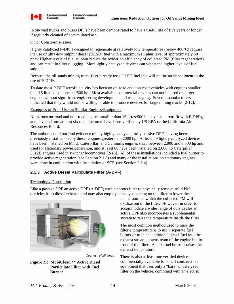
2.1.3 Active Diesel Particulate Filter (A-DPF)
Technology Description
Like a passive DPF an active DPF (A-DPF) uses a porous filter to physically remove solid PM particles from diesel exhaust, and may also employ a catalyst coating on the filter to lower the
temperature at which the collected PM will oxidize out of the filter. However, in order to accommodate a wider range of duty cycles an active DPF also incorporates a supplemental system to raise the temperature inside the filter.
The most common method used to raise the filter’s temperature is to use a separate fuel burner or to inject additional diesel fuel into the exhaust stream, downstream of the engine but in front of the filter. As this fuel burns it raises the exhaust temperature.
There is also at least one verified device commercially available for small construction equipment that uses only a “bare” uncatalyzed filter on the vehicle, combined with an electric
Courtesy of Miratech
Figure 2.3 MobiClean ™ Active Diesel Particulate Filter with Fuel Burner

Emissions Reduction Options for Oil Sands Mining Fleet
M.J. Bradley & Associates 15 March 2008
heating element.11 While the vehicle is operating the filter continually collects PM. Daily, typically at night, the user must plug the heating element into a power outlet, which uses electricity to create enough heat to burn all of the collected PM out of the filter in a few hours.
Because they incorporate a method to increase the exhaust temperature as required, or otherwise burn off collected soot, A-DPF systems can be used on a much wider range of engines and duty cycles, including virtually all construction equipment.
Potential Emissions Reductions
A-DPFs have been verified to reduce PM emissions by 85% or more [2-1]. A-DPFs that incorporate a catalyst also reduce VOC and CO emissions by 60 to 90%, while non-catalyzed active DPFs will reduce CO emissions by approximately 10% and VOC emissions by approximately 20%. A-DPFs do not affect NOx emissions12.
On-vehicle Space Claim
Like P-DPFs, A-DPFs are sized based primarily on peak exhaust flow volume and engine-out PM levels. These devices use the same filter substrates as P-DPFs and are similarly sized.
Minimum A-DPF filter volume will be at least three times engine displacement, and at least one manufacturer’s device will likely be much larger [2-6]. For a 3,500 hp Tier 1 engine with 100 litres displacement a DPF with a minimum volume of 300 litres and a minimum cross sectional area of approximately 0.75 square meters would therefore be required.
As with P-DPFs, individual square substrates can be stacked to create a single, larger brick to accommodate large engines. Also, for large engines round substrates can be canned individually and combined in a secondary housing, or the engine exhaust can be split and routed to multiple individual devices.
Exhaust Temperature Requirements
A-DPFs do not have a minimum engine-out exhaust temperature requirement because they incorporate a method to increase exhaust temperature as required for filter regeneration. Virtually all DPFs will include a back pressure monitoring system because as PM collects in the filter the back pressure on the engine will rise. There are essentially three protocols for initiating regeneration of an active DPF: (1) automatically add fuel and trigger regeneration of the filter when the back pressure rises above a set level (2) automatically add fuel and trigger a regeneration after a set time period (engine-on time), and (3) require the equipment operator to manually trigger a regeneration event.
Cost / Installation
For very large engines A-DPFs will have similar cost as P-DPFs. Based on extrapolation of U.S.EPA estimated DPF costs for 250 hp non-road engines, as well as manufacturer estimates of the cost of larger devices, an A-DPF for a 3,500 hp Tier 1 engine with 100 litres engine displacement will cost between $100,000 and $150,000 [2-9]. As discussed above, larger engines generally require more complicated packaging and/or exhaust routing to the A-DPF, which increases cost.
Per engine costs for “cleaner” Tier 2 engines are likely to be somewhat lower because the filter substrates can be marginally smaller.
11 This is the Cleaire Horizon.
12 If a fuel burner is used for regeneration NOx emissions may increase marginally. NOx emissions from external combustion burners are typically much lower than from diesel engines, and typically less than 5% additional fuel is combusted in the fuel burner.
Emissions Reduction Options for Oil Sands Mining Fleet
M.J. Bradley & Associates 16 March 2008
Installation time will also be similar for A-DPFs as for P-DPFs. It is likely that a complete “production” A-DPF installation on a large mining truck will take 20 – 40 hours, and require a vehicle to be out of service for 2 – 4 days. Prototype installations will likely take longer. However, in either case A-DPF installation may be able to be combined with other scheduled maintenance activities.
On-going Operating Costs
A-DPFs may increase fuel consumption by up to 5% because of increased engine back pressure and the additional fuel required to regenerate the filter [2-14]. The actual fuel penalty will depend on engine-out PM levels and average exhaust temperature in the equipment’s duty cycle. This will increase annual fuel use for a 218 tonne mining truck (2,500 hp) by up to 56,000 litres per year and for a 363 tonne mining truck (3,500 hp) by up to 80,000 litres per year.3 Assuming $0.68 per litre for diesel fuel4 this will increase annual fuel costs by up to $38,000 for a 218 tonne truck and $54,000 for a 363 tonne truck.
Whether a system is passive or active, non-combustible components of lubricating oil collect as ash in the DPF filter over time. Periodically the filter substrates must be cleaned to remove this ash. DPFs for smaller on-road engines are generally designed so that the filter element can be easily removed from the vehicle and cleaned in a special machine. For large non-road engines the DPF may be designed to be cleaned in place on the vehicle by accessing both sides of the filter from access doors in the filter housing. The cleaning process will generally involve blowing compressed air through the outlet face of the filter and collecting the ash that is blown out the inlet side. Filter cleaning in place on the vehicle is estimated take 2-3 hours [2-11].
The required cleaning interval will primarily depend on how much lubricating oil is burned by the engine, and the characteristics of the oil. Tighter engines that burn less oil will require filter cleaning less often than engines than burn more oil. The use of low ash content lubricating oils compatible with reduced sulphur fuels will also extend required cleaning intervals. On-road trucks retrofit with DPF generally require filter cleaning every 12 – 24 months (4,000 – 6,000 engine operating hours). Large non-road engines may require filter cleaning as often as every 2,000 hours [2-11]. Assuming 6,000 hours of engine operation per year, a DPF installed on a large mining truck will require cleaning 1 – 3 times annually.
Since DPFs are always packaged in stainless steel containers, installed devices usually last at least six years.
Other Constraints/Issues
Lightly catalyzed and non-catalyzed A-DPFs can withstand higher fuel sulphur levels than highly catalyzed P-DPFs. Fuel with up to 500 ppm sulphur can be used.
Examples of Prior Use on Similar Engines/Equipment
Numerous on-road and non-road engines smaller than 15 litres/500 hp have been retrofit with A-DPFs, and devices from at least three manufacturers have been verified by US EPA or the California Air Resources Board.
At least 49 lightly catalyzed devices with fuel burner for active regeneration have been installed on MTU, Caterpillar, and Cummins engines sized between 2,000 and 3,500 hp and used for stationary power generation, and at least 68 have been installed on 2,000 hp Caterpillar 3512B engines used in switcher locomotives [2-13]. Many of the installations on stationary engines were done in conjunction with installation of SCR (see Section 2.1.4)
Emissions Reduction Options for Oil Sands Mining Fleet
M.J. Bradley & Associates 17 March 2008
2.1.4 Selective Catalytic Reduction (SCR)
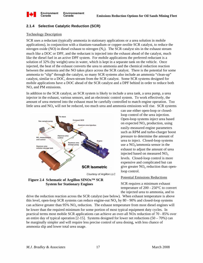
Technology Description
SCR uses a reductant (typically ammonia in stationary applications or a urea solution in mobile applications), in conjunction with a titanium-vanadium or copper-zeolite SCR catalyst, to reduce the nitrogen oxide (NO) in diesel exhaust to nitrogen (N2). The SCR catalyst sits in the exhaust stream much like a DOC or DPF, and the reductant is injected into the exhaust ahead of the catalyst, much like the diesel fuel in an active DPF system. For mobile applications the preferred reductant is a solution of 32% (by weight) urea in water, which is kept in a separate tank on the vehicle. Once injected, the heat of the exhaust converts the urea to ammonia and the chemical reduction reaction between the ammonia and the NO takes place across the SCR catalyst. There is the potential for some ammonia to “slip” through the catalyst, so many SCR systems also include an ammonia “clean-up” catalyst, similar to a DOC, down-stream from the SCR catalyst. Some SCR systems designed for mobile applications have a DOC ahead of the SCR catalyst and a DPF behind in order to reduce both NOx and PM emissions.
In addition to the SCR catalyst, an SCR system is likely to include a urea tank, a urea pump, a urea injector in the exhaust, various sensors, and an electronic control system. To work effectively, the amount of urea metered into the exhaust must be carefully controlled to match engine operation. Too little urea and NOx will not be reduced, too much urea and ammonia emissions will rise. SCR systems
can use either open-loop or closed-loop control of the urea injection. Open-loop systems inject urea based on expected NOx production, using easily-measured engine parameters such as RPM and turbo-charger boost pressure to determine the amount of urea to inject. Closed-loop systems use a NOx/ammonia sensor in the exhaust to adjust the amount of urea injected based on measured NOx levels. Closed-loop control is more expensive and complicated but can give greater NOx reduction than open-loop control.
Potential Emissions Reductions
SCR requires a minimum exhaust temperature of 200 - 250°C to convert the injected urea to ammonia, and to
drive the reduction reaction across the SCR catalyst (see below). When exhaust temperature is above this level, open-loop SCR systems can reduce engine-out NOx by 80 - 90% and closed-loop systems can achieve greater than 95% NOx reduction. The exhaust temperature from most diesel engines will be lower than the required minimum for some portion of most typical equipment duty cycles. In practical terms most mobile SCR applications can achieve an over-all NOx reduction of 70 - 85% over an entire day of typical operation [2-15]. Systems designed for lower net reductions (50 – 70%) can be marginally simpler and will require less precise control of urea dosing, with less chance of ammonia slip and lower total urea usage.
Courtesy of Argillon LLC
Figure 2.4 Schematic of Argillon SINOx™ SCR System for Stationary Engines

Emissions Reduction Options for Oil Sands Mining Fleet
M.J. Bradley & Associates 18 March 2008
SCR itself does not significantly affect CO, VOC, or PM emissions; however, many commercial SCR systems for mobile applications are deployed in conjunction with a DOC or DPF to reduce the potential for ammonia slip and to reduce these pollutants.
On-vehicle Space Claim
SCR catalysts are sized based primarily on exhaust flow volume, expected NOx levels, expected exhaust temperature, and allowable back pressure.
Stationary systems typically use titanium vanadium catalysts with large pore size. These catalysts are relatively inexpensive and do not impose much back pressure on the engine, but they are very large, with total catalyst volume 10 – 20 times engine displacement. Mobile applications often use copper-zeolite catalysts with much higher cell density. These catalysts are more expensive and impose higher back pressure on the engine but they offer the opportunity of being much smaller. Minimum copper-zeolite catalyst volume will be approximately 2 - 3 times engine displacement for a Tier 1 engine and may be slightly less for a Tier 2 engine [2-16]. For a 3,500 hp Tier 1 engine with 100 litres displacement a 300 litre copper-zeolite SCR catalyst with a minimum cross sectional area of at least 0.75 square meters would therefore be required. If titanium-vanadium catalysts are used the required catalyst volume might be ten times greater.
SCR catalysts are typically constructed as “bricks” with square cross section, and individual catalyst bricks are usually stacked in a single metal enclosure (see Figure 2.4).
Some systems may require an exhaust path as long as 4.5 meters between the urea injector and SCR catalyst to ensure that the urea solution is well mixed with exhaust and converts to ammonia before reaching the catalyst.
In addition to the SCR catalyst, a vehicle will require a urea storage tank. The target mining trucks typically have fuel tanks that hold approximately 4,500 litres, so this tank will need to have a volume of 140 - 350 litres in order to match on-board urea storage to on-board fuel storage, allowing the urea tank to require filling only when the vehicle is refueled. A discussion of typical urea use is provided below.
Exhaust Temperature Requirements
SCR requires a minimum exhaust temperature of 200 - 250°C to convert the injected urea to ammonia and to drive the reduction reaction across the SCR catalyst. SCR control systems include exhaust temperature monitors, and if the measured exhaust temperature is below the required minimum no urea solution will be injected.
Given the way that oil sands mining trucks are typically used, as described in Section 1.1, it is likely that their diesel engines will be operating at 75% or more of peak power while moving up out of the mine fully loaded. During this portion of their duty cycle exhaust temperature should be well above the minimum required for SCR operation, and 90% or greater control of engine-out NOx can be achieved with SCR. When waiting to unload and transiting back to the mine face empty the engine is likely to be operating at less than 20% of peak power, and exhaust temperatures are likely to be too cool for SCR operation. While the empty portion of the duty cycle may encompass up to 50% of the total vehicle operation time, fuel use and NOx emissions while empty will be low. The vast majority of total fuel use and NOx emissions from these mining trucks will be while the vehicles are loaded and exhaust temperatures are high enough for SCR operation. As with other mobile SCR applications, a net NOx reduction of 75% or more should be easily achievable from the target mining trucks.
Cost / Installation
Based on responses from SCR vendors, an SCR system for a 3,500 hp Tier 1 mining truck engine with 100 litres engine displacement is expected to cost between $150,000 and $250,000 [2-17]. The cost

Emissions Reduction Options for Oil Sands Mining Fleet
M.J. Bradley & Associates 19 March 2008
of devices for smaller engines will be generally proportional to engine size, though the average $/hp cost may be less for smaller engines than for larger engines. Per engine costs for “cleaner” Tier 2 engines are likely to be somewhat lower because the SCR catalysts can be marginally smaller.
For 2,500 – 3,500 hp engines it is likely that significant modifications to the existing exhaust piping will be required, and that other components in the engine compartment may need to be relocated to find adequate space for installation of the SCR catalyst. In addition, a urea tank and supply lines, a urea injector, an electronic control module, and various sensors and wiring harnesses must be installed. The ECM will require connection to the vehicle’s electrical power system and the injector is likely to require connection to the vehicle’s air system, or may be supplied by a dedicated air compressor driven electrically.
It is likely that a complete “production” SCR installation on a large mining truck will take 40 – 60 hours, and require a vehicle to be out of service for 4 – 6 days. Prototype installations will likely take longer. In either case SCR installation may be able to be combined with other scheduled maintenance activities.
On-going Operating Costs
Depending on the back pressure imposed on the engine an SCR system may increase fuel use by 0 – 3% [2-18]. This will increase annual fuel use for a 218 tonne mining truck (2,500 hp) by up to 33,000 litres per year and for a 363 tonne mining truck (3,500 hp) by up to 48,000 litres per year3. Assuming $0.68 per litre for diesel fuel4 this will increase annual fuel costs by $0 - $22,000 for a 218 tonne truck and $0 - $33,000 for a 363 tonne truck.
SCR also requires the use of urea reductant. Urea is a salt which is typically sold as a granular solid and is a common industrial chemical used primarily in the production of fertilizer. When mixed with water the urea goes into solution.
For mobile SCR applications a 32% (by weight) solution of urea in water is typically used as the reductant. Approximately one tonne of urea salt is required to reduce one tonne of NOx. In practical terms, to achieve 75% control of NOx a Tier 1 construction engine greater than 750 hp would require approximately one litre of 32% urea solution for every thirteen litres of diesel fuel used (7.5 %), a Tier 2 engine would require approximately one litre of urea solution for every twenty litres of diesel fuel used (5%), and a Tier 4 engine would require approximately one litre of urea solution for every thirty three litres of diesel fuel used (3%).
Annual urea use is estimated to be 84,000 litres for a 218 tonne mining truck with a 2,500 hp Tier 1 engine, and 120,000 litres for a 363 tonne mining truck with a 3,500 hp Tier 1 engine3.
Purchased in bulk, a 32% urea solution is expected to cost $0.31- $0.36 per litre [2-19]. The urea required for SCR would therefore cost $26,000 - $30,000 per year for a 218 tonne mining truck with a 2,500 hp Tier 1 engine, and $37,000 - $43,000 per year for a 363 tonne mining truck with a 3,500 hp Tier 1 engine.
SCR catalysts can have a useful life of 10,000 – 40,000 engine hours depending on engine maintenance and operating conditions. Realistically, SCR catalysts installed on large mining trucks will likely require replacement every 3 – 4 years. The cost of catalyst replacement for a 3,500 hp engine is estimated to be $20,000 - $40,000 [2-20]. Other components of the SCR system will have defined preventive maintenance intervals of 2,000 – 4,000 operating hours, and typically will include checks of system operation and replacement of filters.
Other Constraints/Issues
To use SCR for oil sands mining trucks a urea purchase and distribution infrastructure will need to be developed. Urea can be purchased and stored on-site in bulk as a solid, and mixed with deionized
Emissions Reduction Options for Oil Sands Mining Fleet
M.J. Bradley & Associates 20 March 2008
water to achieve the required 32% solution just before loading the solution onto the mining trucks. Alternately it can be purchased and stored in bulk as a pre-mixed 32% urea solution.
Both in bulk storage and on the vehicle the 32% urea solution must be kept above -12°C. At lower temperatures the urea salt will start to precipitate out of solution [2-21]. If the soultion is subsequently heated and aggitated the solid urea will dissolve back into solution.
For oil sands mining trucks it will likely be necessary to both insulate and heat the on-board urea storage tanks, which can be achieved using engine coolant. If a vehicle will not be used for an extended period, and will be stored outside when ambient temperatures are low, it may be advisable to drain the urea tank, or keep it warm with an auxiliary heater.
Examples of Prior Use on Similar Engines/Equipment
The authors could not find evidence of any SCR systems having been previously installed on large mining trucks. However, SCR is installed widely on stationary diesel engines greater than 2,000 hp used for electrical power generation, and on marine vessels.
SCR has been installed on at least 425 stationary diesel engines greater than 2,000 hp, including at least 226 MTU, Caterpillar, and Cummins engines sized between 2,000 and 3,500 hp [2-22]. Many of these installations included a DOC or a DPF. SCR has also been installed on at least 100 marine engines greater than 2,000 hp, including at least 16 Caterpillar engines sized between 2,500 and 3,500 hp, and on at least four 3,200 hp locomotive engines.
2.1.5 NOx Reduction Catalyst (NRC)
Technology Description
NOx reduction catalyst systems are similar to SCR systems, but in lieu of a urea solution they use a hydrocarbon reductant (typically diesel fuel), in conjunction with a hydrocarbon-optimized catalyst, to reduce the NO in diesel exhaust to N2. The NRC catalyst sits in the exhaust stream much like an SCR catalyst, and the diesel fuel reductant is injected into the exhaust ahead of the catalyst. Once injected the hydrocarbons in the extra fuel take part in a chemical reduction reaction with NO across the NRC catalyst. There is the potential for an increase in unburned hydrocarbon and CO emissions, so most NRC systems also include an oxidation catalyst down-stream from the NRC catalyst.
In addition to the NRC catalyst, the system is likely to include a fuel pump, a fuel injector in the exhaust, various sensors, and an electronic control system. The diesel fuel reductant is typically taken from the vehicle’s main fuel tank. To minimize the amount of extra fuel used as a reductant, as well as increased CO and VOC emissions, the amount of fuel metered into the exhaust must be controlled to match engine operation. NRC systems typically use open-loop control of the diesel fuel reductant injection, based on easily measured engine parameters such as RPM and turbo-charger boost pressure.
Potential Emissions Reductions
In on-road applications NRC systems have been verified to reduce NOx emissions by 25%. When coupled with a DPF, as is typical, they have also been verified to reduce CO emissions by 90%, VOC emissions by 65%, and PM emissions by 85% or more [2-1].
Emissions Reduction Options for Oil Sands Mining Fleet
M.J. Bradley & Associates 21 March 2008
On-vehicle Space Claim
NRC catalysts are very similar to SCR catalysts and they use the same/similar substrates. Like SCR catalysts they are sized based primarily on exhaust flow volume, expected NOx levels, expected exhaust temperature, and allowable back pressure.
NRC systems are not typically used on stationary engines, with virtually all commercially available systems designed for mobile applications. As with mobile SCR systems, minimum NRC catalyst volume will be approximately 2 - 3 times engine displacement for either a Tier 1 or Tier 2 engine [2-23]. For a 3,500 hp Tier 1 engine with 100 litres displacement a 300 litre NRC catalyst with a minimum cross sectional area of at least 0.75 square meters would therefore be required.
Exhaust Temperature Requirements
Exhaust temperature requirements for NRC systems are similar to those for SCR systems.
Cost / Installation
The only currently commercially available NRC system is designed and verified for on-road vehicles with less than 15 litres engine displacement and 500 hp. The manufacturer also recommends that it not be applied to non-road engines greater than 400 hp. This device combines an NRC catalyst and a catalyzed DPF, and its list price is $20,500. The manufacturer indicated that the average $/hp costs would be greater for larger engines due to the need for more complicated packaging [2-24]. It is likely that an NRC system for a 3,500 hp Tier 1 mining truck engine with 100 litres engine displacement would be similar in price to an SCR system, at between $150,000 and $250,000.
Installation time and complexity will also be similar to SCR systems. The major installation difference between NRC and SCR systems is that a urea tank will not be required with an NRC system nor will local urea infrastructure (e.g., heated tanks) be required. As with SCR, it is likely that a complete “production” NRC installation on a large mining truck will take 40 – 60 hours, and require a vehicle to be out of service for 4 – 6 days, and prototype installations will likely take longer. In either case NRC installation may be able to be combined with other scheduled maintenance activities.
On-going Operating Costs
Current commercial NRC systems installed on on-road vehicles use an additional 3 -5% diesel fuel as a reductant [2-25]. This would increase annual fuel use for a 218 tonne mining truck (2,500 hp) by 33,000 – 55,000 litres per year and for a 363 tonne mining truck (3,500 hp) by 48,000 – 80,000 litres per year3. Assuming $0.68 per litre for diesel fuel4 this will increase annual fuel costs by $22,500 - $37,000 for a 218 tonne truck and $33,000 - $55,000 for a 363 tonne truck.
According to the manufacturer, the catalysts used in current commercial NRC systems have a useful life of 5,000+ engine hours. High temperature/high load duty cycles will have shorter life, and catalyst life will be extended in less demanding duty cycles. If this system was used on a large mining truck the NRC catalyst might require replacement as often as every 1 – 2 years. The cost of catalyst replacement for a 3,500 hp engine is estimated to be $25,000 - $30,000 [2-26]. Other components of the NRC system will have defined preventive maintenance intervals of 2,000 – 4,000 operating hours.
Courtesy of Cleaire
Figure 2.5 Longview ™ NRC System For an On-road Truck

Emissions Reduction Options for Oil Sands Mining Fleet
M.J. Bradley & Associates 22 March 2008
Typical preventive maintenance tasks will include checks of system operation and replacement of filters.
Other Constraints/Issues
Only one manufacturer currently sells verified, commercial NRC systems. These systems are designed primarily for on-road engines with maximum displacement/power of 15 litres/500 hp. Significant engineering effort would be required to adapt this system to 2,500 – 3,500 hp engines. The current manufacturer is focused on the on-road truck market and may or may not be interested in the retrofit market for very large engines.
Examples of Prior Use on Similar Engines/Equipment
The largest diesel engine on which a commercial NRC system has been installed to date is a 1,200 hp stationary engine that powers a one megawatt generator. This installation includes six “standard” on-road truck systems ganged together [2-27].
2.1.6 Exhaust Gas Recirculation (EGR)
Technology Description
In an EGR system some of the exhaust gas from the diesel engine is re-routed back to the engine intake manifold and mixed with the intake air before it enters the cylinder. This introduces inert gas (carbon dioxide) into the cylinder that absorbs heat and reduces peak combustion temperature in the engine, thus reducing the production of NOx during combustion. Technically, EGR is not an “after-treatment” technology because it fundamentally affects the engine’s combustion cycle and reduces engine-out emissions.
Most on-road diesel engines are now being delivered with high-pressure cooled EGR systems that redirect a portion of exhaust flow to the air intake using an electronically controlled valve mounted in the exhaust circuit just down-stream of the engine turbo-charger. Control of this exhaust valve in response to differing engine conditions is accomplished using the engine’s electronic control module (ECM). Prior to entering the air intake, the redirected exhaust flow is cooled using a separate heat exchanger that is installed in the normal engine cooling loop. The redirected exhaust flow is routed to the high pressure side of the air intake (down stream of the turbo charger). These types of systems could theoretically be retrofit on an electronically controlled engine, but would require significant hardware changes and new engine control software.
Low-pressure EGR systems are also commercially available that can theoretically be retrofit onto virtually any diesel engine. These systems typically redirect exhaust flow to the low pressure side of the air intake (in front of the turbo charger) using a valve mounted much further back in the exhaust system. This valve is
Courtesy of Johnson Matthey
Figure 2.6 EGRT ™ Low Pressure EGR System for Onroad Truck

Emissions Reduction Options for Oil Sands Mining Fleet
M.J. Bradley & Associates 23 March 2008
typically controlled with an electronic control module separate from the engine ECM. In commercially available systems the EGR valve is often located down stream of a DPF, so that the redirected exhaust that re-enters the combustion chamber is much cleaner than in high-pressure EGR systems. Low pressure EGR systems may or may not include a heat exchanger to cool the redirected exhaust before it enters the air intake.
Potential Emissions Reductions
In on-road applications retrofit low-pressure EGR systems have been verified to reduce NOx emissions by 40%. In non-road stationary engines they have been verified to reduce NOx emissions by 50%. When coupled with a DPF, as is typical, they have also been verified to reduce CO and VOC emissions by 60 - 90% and PM emissions by 85% or more [2-1].
On-vehicle Space Claim
The on-vehicle space claim for a retrofit EGR system will vary significantly depending on engine compartment layout, but will be significantly less than the space claim required for SCR or NRC catalysts [2-27]. The major components of the system include a valve inserted in the existing exhaust path, additional exhaust piping to redirect a portion of the exhaust to the air intake, temperature and pressure sensors, and a small electronic control module (see Figure 2.6).
All current commercially available systems include a DPF as part of the installation. Space claim requirements of a DPF are described in Section 2.1.2.
Exhaust Temperature Requirements
There are no minimum exhaust temperature requirements for the use of EGR. However, systems that incorporate a DPF are constrained by the exhaust temperature requirements of the DPF.
Cost / Installation
There is one commercially available retrofit EGR system verified for use on non-road engines, primarily stationary engines used for power generation and agricultural pumps. The manufacturer indicates that the “standard” product could be installed on engines as large as 2,000 hp (for example the Caterpillar 3512B) and that the cost of the system would be approximately $20,000 plus the cost of a DPF [2-28]. Adaptation of this system to larger engines would require significant engineering time to develop a practical installation, and costs would be higher.
On-going Operating Costs
The manufacturer of one commercial system claims that they have not seen any fuel penalty in “nine years of testing in various applications” [2-29], although these claims could not be independently verified.
Other Constraints/Issues
There are two retrofit EGR systems currently commercially available. One is specifically designed for non-road stationary engines – the manufacturer of this system indicated that it could theoretically be adapted to the large diesel engines used in mining trucks, but that as a small company they would not likely be in a position to do so [2-30]. The other system is specifically designed for on-road vehicles – the manufacturer of this system indicated that they would not encourage its use on large non-road engines [2-31].
Examples of Prior Use on Similar Engines/Equipment
The largest engine to which a retrofit EGR system has been applied is a 600 hp Caterpillar 3406C used to power a 500 kW generator [2-32].

Emissions Reduction Options for Oil Sands Mining Fleet
M.J. Bradley & Associates 24 March 2008
Table 2.2 Summary of PM Reduction Retrofit Technologies
DOC Passive DPF Active DPF PM Reduction 25+% 85+% 85+% On-Vehicle Space Claim
Minimum 1-1.25x engine displacement 3x engine displacement 3x engine displacement 3,500 hp engine 100-125 litres / 0.65 m2 300 litres / 0.75 m2 300 litres / 0.75 m2
Min Exhaust Temp. Highly catalyzed 200-280°C for 40-50%
engine-on time for filter regeneration
Lightly catalyzed
150°C for any VOC/PM reduction
400-450°C for 40-50% engine-on time for filter
regeneration
None
Installation Cost 3,500 hp engine $20,000 - $30,000 $100,000 - $150,000 $100,000 - $150,000
Installation Time 10+ hours 20-40 hrs / 2 – 4 days 20-40 hrs / 2 – 4 days Fuel Penalty None 1 – 3% 3 – 5% Incremental Annual Operating Costs
363 tonne truck
Virtually none
+$11,000 - $33,000 fuel Filter cleaning 1- 3 times (x 2-3 hrs per cleaning)
+$33,000 - $54,000 fuel Filter cleaning 1- 3 times (x 2-3 hrs per cleaning)
Constraints May not be applicable to Tier 0 engines
Must use ULSD with highly catalyzed devices
None
Commercial Availability
Commercially available for 2,000+ hp stationary
engines
Highly catalyzed – only commercially available for engines <500 hp / 15
litres Lightly catalyzed
commercially available for 2,000+hp stationary,
locomotive engines
Commercially available for 2,000+hp stationary,
locomotive engines

Emissions Reduction Options for Oil Sands Mining Fleet
M.J. Bradley & Associates 25 March 2008
Table 2.3 Summary of NOx Reduction Retrofit Technologies
SCR NRC EGR NOx Reduction 70 – 85% 25% 50% On-Vehicle Space Claim
Minimum 2 – 3x engine displacement 2-3x engine displacement Minimal – EGR only 3x engine displacement
if used with DPF 3,500 hp engine Catalyst: 200 – 300 litre
0.75 m2
Urea tank: 140 – 350 litre
200 – 300 litre / 0.75 m2 Minimal – EGR only DPF: 300 litres / 0.75 m2
Min Exhaust Temp. 200-250°C for any NOx reduction
200-250°C for any NOx reduction
None – EGR only (see DPF above)
Installation Cost 3,500 hp engine $150,000 - $250,000 $150,000 - $250,000 $20,000 - $50,000
Plus DPF Installation Time 40-60 hrs / 4 – 6 days 40-60 hrs / 4 – 6 days Unknown Fuel Penalty 0 – 3% 3 – 5% None Urea Use Tier 1 7.5% of fuel
Tier 2 5.0% of fuel Tier 4 3.0% of fuel
None
None
Incremental Annual Operating Costs
363 tonne truck (Tier1)
+$0 - $33,000 fuel
+$37,000 - $43,000 urea Replace SCR catalyst
every 3-4 years ($20,000 -$40,000)
+$33,000 - $55,000 fuel Replace NRC catalyst
every 1-2 years ($25,000 -$30,000)
Minimal
Constraints Urea solution must be kept above -12°C
Limited commercial availability for large
engines
Limited commercial availability for large
engines Commercial Availability Commercially available for
2,000+ hp stationary, marine, locomotive engines
Only commercially available for engines <500 hp / 15 litres
Only commercially available for engines <600 hp / 15 litres

Emissions Reduction Options for Oil Sands Mining Fleet
M.J. Bradley & Associates 26 March 2008
2.2 Engine Replacement/Upgrade Options Environment Canada emission standards for the non-road engines used in mining trucks apply to new engines only. As emission standards for new engines get more stringent over time there is no requirement for existing engines to meet the more stringent standard. Yet some existing engines may be able to be upgraded with new components and technologies that will lower emissions of both NOx and PM. Such an approach is likely to be very cost-effective if done in conjunction with a regularly scheduled engine overhaul.
As cleaner engines that meet more stringent emission standards become commercially available in new trucks it is also generally possible to “retire” old engines without retiring the entire vehicle – by removing the old engine and “re-powering” with a new, cleaner engine. To reduce the net incremental cost, such an approach is best done in lieu of a regularly scheduled overhaul of the old engine.
2.2.1 Tier 0/1 – Tier 2 Upgrade/Repower The engines used in 218 – 363 tonne non-road haul trucks typically require a major overhaul every 15,000 – 16,000 operating hours. Since these trucks are used for 6,000 – 7,200 hours per year, their engines will typically get rebuilt every 2 -3 years, and an engine will typically get re-built 3 - 4 times in the life of a truck [2-33].
One approach to reducing emissions from existing trucks with unregulated (Tier 0) and Tier 1 engines is to upgrade the engine during a regularly scheduled overhaul, or to replace the engine with a new engine that meets the current Tier 2 emission standards.
Description
To upgrade an unregulated engine to meet Tier 1 emission standards an engine overhaul might include one or more of the following: a more efficient turbo-charger, new pistons or piston liners that will provide better oil control, new fuel injectors, and changes in engine timing.
Many unregulated non-road engines use mechanical unit injectors. To further reduce emissions to meet Tier 2 emission standards electronic fuel control is generally required, and this is not something that can easily be retrofit onto an existing engine. To bring a mining truck with an unregulated engine to Tier 2 emission standards a re-power will likely be required.
Many non-road engines built to meet Tier 1 emission standards include electronic fuel control and electronic unit injectors. Compared to a Tier 1 engine, a Tier 2-compliant engine is likely to include higher fuel injection pressures, perhaps using a common rail system, and may also incorporate exhaust gas recirculation, and/or a different type of charge air cooler to reduce air intake temperature. Many of these changes are difficult to retrofit onto an existing engine. To bring a mining truck with a Tier 1 engine to Tier 2 emission standards a re-power will likely be required.
Potential Emissions Reductions
Upgrading an unregulated engine with advanced components during an overhaul could reduce NOx emissions by up to 35% and also marginally reduce PM emissions.
Replacing an unregulated engine with a Tier 2 engine could reduce NOx emissions by up to 55% and PM emissions by approximately 65%.
Replacing a Tier 1 engine with a Tier 2 engine could reduce NOx emissions by 30% and PM emissions by 63%.
Cost / Installation
Rebuilding or over-hauling a 2500 – 3500 hp engine in a non-road mining truck typically costs $250,000 - $500,000 [2-34]. When upgrading a non-regulated engine during overhaul, the

Emissions Reduction Options for Oil Sands Mining Fleet
M.J. Bradley & Associates 27 March 2008
incremental cost of the upgraded components could increase total overhaul costs by approximately 20%, or $50,000 - $100,000 per engine [2-35].
Replacing an old engine with a new engine rather than rebuilding it will likely cost at least twice as much as the overhaul would have cost – adding an additional $500,000 or more per truck [2-34].
Upgrading during engine rebuild typically will not significantly increase the amount of time that the truck is out of service for the rebuild.
Repowering in lieu of an engine rebuild will likely increase out-of-service time by a week or more since it may require extensive modifications to the vehicle structure, wiring harnesses, and engine air intake and cooling systems.
On-going Operating Costs
Upgraded or new Tier 2-compliant engines are not expected to have higher operating costs than re-built unregulated or Tier 1-compliant engines. A new Tier-2 compliant engine may provide greater reliability and lower fuel13 use than an older unregulated engine, reducing on-going operating costs after the repower.
Other Constraints/Issues
Some engine manufacturers, for example Caterpillar, sell emissions upgrade kits for unregulated engines smaller than 1000 hp used in construction equipment. Upgrade kits are also available for some marine engines as large as 2500 hp. However, it is not clear whether upgrade kits are currently commercially available for the very large engines used in 218 – 363 tonne mining trucks.
At least one manufacturer is currently conducting validation tests of new Tier 2-compliant replacement engines retrofit into older ultra class mining trucks. This testing is expected to be completed by the end of 2008 [2-36]
2.2.2 Tier 2 – Tier 4 Repower Beginning in the 2011 model year, non-road engines greater than 750 hp will be required by Environment Canada to meet more stringent Interim Tier 4 emission standards.
By mid-to-late 2013 Interim Tier 4 compliant replacement engines should be available for retrofit into older non-road mining trucks, if the engine manufacturers project that there will be a commercial market for them.
Description
In comparison to Tier 2 standards the Interim and FinalTier 4 non-road standards require significant reductions of both NOx and PM. It is not clear what technologies will be used to meet these Tier 4 emission standards for large non-road engines.
Some of the approaches that might be taken by engine manufacturers to meet the Tier 4 non-road standards include: higher fuel injection pressures, multiple injection events, variable geometry turbo-chargers, exhaust gas re-circulation, changes in engine timing, and exhaust after-treatment. In terms of after-treatment approaches, a standard diesel oxidation catalyst may be required to meet the Interim Tier 4 PM standard starting in model year 2011, while a high-performnace DOC or a diesel particulate filter might be required to meet the Final Tier 4 PM standard beginning in the 2015 model year.
13 Repowers of main and auxilliary engines in tug boats subsidized by the Port Authority of New York and New Jersey resulted in reductions in brake-specific fuel comsumption of 5 – 15% for new Tier 2-compliant engines compared to unregulated engines.

Emissions Reduction Options for Oil Sands Mining Fleet
M.J. Bradley & Associates 28 March 2008
Potential Emissions Reductions
A Tier 4 compliant engine will have 45% lower NOx emissions than a Tier 2 compliant engine. An engine that complies with the interim Tier 4 PM standards will have 50% lower PM emissions than a Tier 2 compliant engine, while an engine that meets the final Tier 4 PM standard will have 80% lower PM emissions than a Tier 2 compliant engine.
Cost / Installation
Given that the exact technology mix is not yet known, it is impossible to predict how much more expensive a Tier 4 compliant replacement engine would be than a Tier 2 compliant engine. However, it is likely that there will be some incremental cost.
On-going Operating Costs
It is likely that Tier 4 engines will have higher operating costs than Tier 2 engines, but given that the exact technology mix is not yet known it is impossible to predict how much higher.
Other Constraints/Issues
Given that the exact technology mix is not yet known it is unclear whether Tier 4 compliant engines will be more difficult to retrofit into older trucks than current Tier 2 engines. However, it is likely that these engines will fit into the same or similar space envelope as existing engines and will not present significant difficulties in retrofitting.
Emissions Reduction Options for Oil Sands Mining Fleet
M.J. Bradley & Associates 29 March 2008
3. Recommendations – Large Mining Trucks
Based on a review of available technologies, as discussed in Section 2, it appears that significant reductions from expected “baseline” emissions of both NOx and PM are possible from the oil sands mining truck fleet. This section discusses several retrofit/upgrade scenarios judged by the authors to be the most practical options for significant reductions. These scenarios are not the only possible approaches to reducing emissions from the mining truck fleet and should be viewed as illustrative of what might be possible, rather than firm recommendations.
To a large extent the modeled scenarios set the outer bounds on what is possible for this fleet, and were specifically designed to highlight the differences between different approaches. There are many other possible scenarios which incorporate a greater variety of technologies and approaches into a single scenario. For clarity of presentation these “intermediate” scenarios were not modeled.
3.1 Mining Truck Emissions Retrofit/Upgrade Scenarios The air pollutant of primary interest to Environment Canada with respect to mobile oil sands mining operations is NOx. The draft regulatory framework, announced in April 2007, contemplates imposing a NOx cap on the entire oil sands sector beginning in 2012 - 2015. This cap would be equivalent to 60% of the projected 2015 baseline NOx emissions absent regulation.
In developing potential retrofit/upgrade scenarios for this report the authors used this projected NOx cap as a guide – the modeled scenarios were intended to achieve a target 40% NOx reduction from the oil sands mining truck fleet in 2015 using different technology approaches. In order to achieve the 2015 target, retrofit activity will have to begin earlier than 2015. All scenarios shown here assume that retrofits will begin in 2012, and will ramp up over time.
The modeled scenarios therefore do not aim to achieve any particular level of PM reduction. Rather, the scenarios project the reduction in PM emissions that would be possible if those mining trucks retrofit with a NOx reduction technology were also retrofit with a PM reduction technology.
The authors evaluated two emissions reduction scenarios. Scenario 1 achieves the required NOx reductions through upgrade/replacement of older engines in some of the mining trucks with new advanced technology engines certified to meet more stringent emission standards. This approach will also reduce PM emissions since both NOx and PM standards for the target engines have gotten more stringent over time.
Scenario 2 achieves the required NOx reductions through retrofit of part of the mining truck fleet with selective catalytic reduction (SCR). This scenario includes two options for achieving corollary PM reductions – retrofit with diesel oxidation catalysts (DOC) or retrofit with diesel particulate filters (DPF).
The number of upgrades/retrofits included in each scenario are shown in Table 3.1.
Under Scenario 1, approximately 46% of the Tier 1 mining trucks expected to be in service in 2016 will be repowered with Tier 2 engines and approximately 75% of the Tier 2 mining trucks expected to be in service in 2016 will be repowered with Tier 4 engines14. The repowered Tier 1 trucks have a
14 This analysis assumes that all current mining trucks have either Tier 1 or Tier 2 engines. Some existing trucks may have unregulated engines. For these trucks an emissions upgrade to Tier 1 standards may be possible in lieu of repowering with a Tier 2 engine, as discussed in Section 2.2.1.

Emissions Reduction Options for Oil Sands Mining Fleet
M.J. Bradley & Associates 30 March 2008
minimum of five years remaining useful life after retrofit, while the repowered Tier 2 trucks have a minimum of six years remaining useful life after retrofit.
Under Scenario 2, approximately 46% of the Tier 1 mining trucks and approximately 62% of the Tier 2 mining trucks expected to be in service in 2016 will be retrofit with SCR to reduce NOx emissions.
Under scenario 2a, all of the trucks retrofit with SCR will also be retrofit with DOC to reduce PM emissions, while under scenario 2b all of the trucks retrofit with SCR will also be retrofit with DPF to reduce PM emissions.
All of the trucks retrofit under Scenario 2 have a minimum of five or six years useful life remaining after retrofit.
Table 3.1 Mining Truck Emissions Reduction Scenarios
Number of Vehicles Completed MINING TRUCK EMISSIONS REDUCTION SCENARIOS 2012 2013 2014 2015 2016 Total
SCENARIO 1 – NOx & PM Reduction
Repower Tier 1 engines with Tier 2 engines 15 15 30
Repower Tier 2 engines with Tier 4 engines 25 75 100 99 299
SCENARIO 2 – NOx Reduction
Retrofit SCR on Tier 1 engines 15 15 30
Retrofit SCR on Tier 2 engines 25 75 150 250
SCENARIO 2a – PM Reduction
Retrofit DOC on Tier 1 engines 15 15 30
Retrofit DOC on Tier 2 engines 25 75 150 250
SCENARIO 2b – PM Reduction
Retrofit DPF on Tier 1 engines 15 15 30
Retrofit DPF on Tier 2 engines 25 75 150 250
As discussed in Section 2, Tier 2 certified engines are already, or will shortly be, available and could be used to repower mining trucks that currently have Tier 1 certified engines (those built prior to the 2006 model year). Beginning with the 2011 model year (likely mid-to-late 2013) Tier 4 certified engines should also become available, and could be used to repower mining trucks that were built between 2007 and 2012 with Tier 2 engines.
With respect to retrofit technologies that can reduce NOx emissions, the authors have chosen to focus on SCR rather than NRC or EGR for two reasons: 1) it will give the greatest reduction per vehicle of the available technologies, and 2) it is likely to be the most commercially viable of the available technologies. As discussed in Section 2, SCR systems are already commercially available for the large 2,000 – 3,500 hp diesel engines that are used in mining trucks, although to date these commercial SCR
This approach would result in significant NOx reductions at lower cost than repowering. For conservatism this analysis used the higher repower cost for all trucks in Scenario 1.
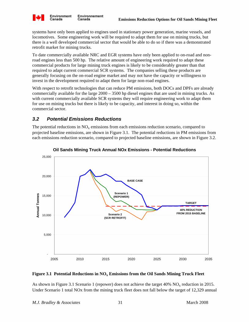
Emissions Reduction Options for Oil Sands Mining Fleet
M.J. Bradley & Associates 31 March 2008
systems have only been applied to engines used in stationary power generation, marine vessels, and locomotives. Some engineering work will be required to adapt them for use on mining trucks, but there is a well developed commercial sector that would be able to do so if there was a demonstrated retrofit market for mining trucks.
To date commercially available NRC and EGR systems have only been applied to on-road and non-road engines less than 500 hp. The relative amount of engineering work required to adapt these commercial products for large mining truck engines is likely to be considerably greater than that required to adapt current commercial SCR systems. The companies selling these products are generally focusing on the on-road engine market and may not have the capacity or willingness to invest in the development required to adapt them for large non-road engines.
With respect to retrofit technologies that can reduce PM emissions, both DOCs and DPFs are already commercially available for the large 2000 – 3500 hp diesel engines that are used in mining trucks. As with current commercially available SCR systems they will require engineering work to adapt them for use on mining trucks but there is likely to be capacity, and interest in doing so, within the commercial sector.
3.2 Potential Emissions Reductions The potential reductions in NOx emissions from each emissions reduction scenario, compared to projected baseline emissions, are shown in Figure 3.1. The potential reductions in PM emissions from each emissions reduction scenario, compared to projected baseline emissions, are shown in Figure 3.2.
Oil Sands Mining Truck Annual NOx Emissions - Potential Reductions
-
5,000
10,000
15,000
20,000
25,000
2005 2010 2015 2020 2025 2030 2035
Ann
ual T
onne
s
BASE CASE
TARGET
40% REDUCTIONFROM 2015 BASELINE
Scenario 1(REPOWER)
Scenario 2 (SCR RETROFIT)
Figure 3.1 Potential Reductions in NOx Emissions from the Oil Sands Mining Truck Fleet
As shown in Figure 3.1 Scenario 1 (repower) does not achieve the target 40% NOx reduction in 2015. Under Scenario 1 total NOx from the mining truck fleet does not fall below the target of 12,329 annual

Emissions Reduction Options for Oil Sands Mining Fleet
M.J. Bradley & Associates 32 March 2008
tonnes until 2020. Peak annual NOx reductions compared to the base case occur in 2016 and 2017, where NOx is reduced by 5,200 annual tonnes in each of these years. Total reductions between 2012 and 2024 are 41,500 tonnes.
Under Scenario 2 (SCR retrofit) annual NOx emissions from the mining truck fleet fall below the target of 12,329 annual tonnes in 2015, and stay well below this level through 2025. Peak annual NOx reductions compared to the base case occur in the years 2015 – 2017, where NOx is reduced by 7,774 annual tonnes in each of these years. Total reductions between 2012 and 2024 are 65,000 tonnes.
As shown in Figure 3.2, Scenario 2b (DPF retrofit) gives the greatest PM reductions from the mining truck fleet while Scenario 2a (DOC retrofit) gives the least. Under Scenario 1 peak PM reductions compared to the base case occur in 2016 and 2017 while they occur in the years 2015 – 2017 under both Scenario 2a and Scenario 2b. Peak annual PM reductions under Scenarios 1, 2a, and 2b are 230 tonnes, 91 tonnes, and 310 tonnes respectively. Total PM reductions between 2012 and 2024 under Scenarios 1, 2a, and 2b are 1,761 tonnes, 739 tonnes, and 2,513 tonnes respectively.
Oil Sands Mining Truck Annual PM Emissions - Potential Reductions
0
200
400
600
800
1000
2005 2010 2015 2020 2025 2030 2035
Ann
ual T
onne
s
BASE CASE
Scenario 1(REPOWER)
Scenario 2a (DOC RETROFIT)
Scenario 2b (DPF RETROFIT)
Figure 3.2 Potential Reductions in PM Emissions from the Oil Sands Mining Truck Fleet
3.3 Cost of Emissions Reductions The major assumptions used to evaluate the costs of the emissions reduction scenarios are shown in Table 3.2. All of these assumptions were taken from the technology discussion in Section 2. For each scenario, both the capital costs for purchase of the required new engines and/or retrofit devices, and
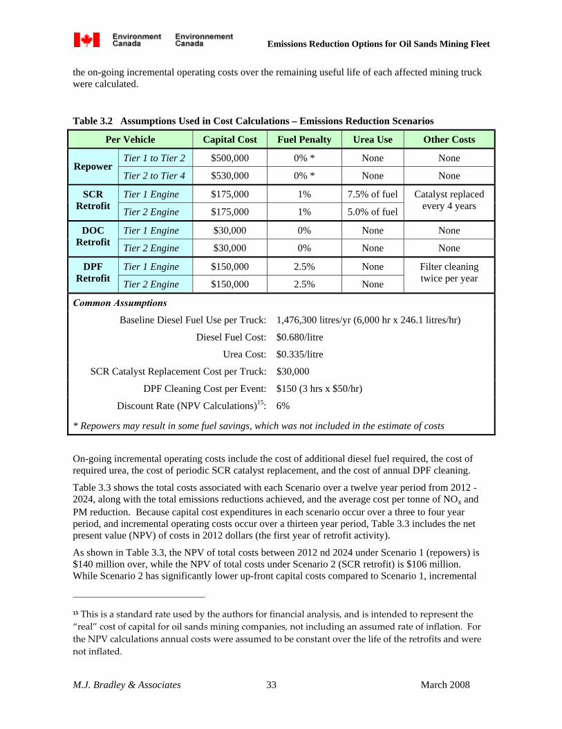
Emissions Reduction Options for Oil Sands Mining Fleet
M.J. Bradley & Associates 33 March 2008
the on-going incremental operating costs over the remaining useful life of each affected mining truck were calculated.
Table 3.2 Assumptions Used in Cost Calculations – Emissions Reduction Scenarios
Per Vehicle Capital Cost Fuel Penalty Urea Use Other Costs
Tier 1 to Tier 2 $500,000 0% * None None Repower
Tier 2 to Tier 4 $530,000 0% * None None
Tier 1 Engine $175,000 1% 7.5% of fuel SCR Retrofit Tier 2 Engine $175,000 1% 5.0% of fuel
Catalyst replaced every 4 years
Tier 1 Engine $30,000 0% None None DOC Retrofit Tier 2 Engine $30,000 0% None None
Tier 1 Engine $150,000 2.5% None DPF Retrofit Tier 2 Engine $150,000 2.5% None
Filter cleaning twice per year
Common Assumptions
Baseline Diesel Fuel Use per Truck: 1,476,300 litres/yr (6,000 hr x 246.1 litres/hr)
Diesel Fuel Cost: $0.680/litre
Urea Cost: $0.335/litre
SCR Catalyst Replacement Cost per Truck: $30,000
DPF Cleaning Cost per Event: $150 (3 hrs x $50/hr)
Discount Rate (NPV Calculations)15: 6%
* Repowers may result in some fuel savings, which was not included in the estimate of costs
On-going incremental operating costs include the cost of additional diesel fuel required, the cost of required urea, the cost of periodic SCR catalyst replacement, and the cost of annual DPF cleaning.
Table 3.3 shows the total costs associated with each Scenario over a twelve year period from 2012 -2024, along with the total emissions reductions achieved, and the average cost per tonne of NOx and PM reduction. Because capital cost expenditures in each scenario occur over a three to four year period, and incremental operating costs occur over a thirteen year period, Table 3.3 includes the net present value (NPV) of costs in 2012 dollars (the first year of retrofit activity).
As shown in Table 3.3, the NPV of total costs between 2012 nd 2024 under Scenario 1 (repowers) is $140 million over, while the NPV of total costs under Scenario 2 (SCR retrofit) is $106 million. While Scenario 2 has significantly lower up-front capital costs compared to Scenario 1, incremental
15 This is a standard rate used by the authors for financial analysis, and is intended to represent the “real” cost of capital for oil sands mining companies, not including an assumed rate of inflation. For the NPV calculations annual costs were assumed to be constant over the life of the retrofits and were not inflated.

Emissions Reduction Options for Oil Sands Mining Fleet
M.J. Bradley & Associates 34 March 2008
on-going operating costs are higher. These two approaches to reducing NOx emissions from the oil sands mining truck fleet can achieve significant reductions at an average cost of $1,600 - $3,400 per tonne of NOx emissions reduced.
Table 3.3 Cost of Emissions Reduction Scenarios – Oil Sands Mining Trucks
$ millions Scenario 1
REPOWER Scenario 2
SCR Scenario 2a
DOC Scenario 2b
DPF
NPV Capital Costs, 2012 - 2024 $140.11 $40.52 $6.95 $34.73
NPV Operating Costs, 2012 - 2024 $0.00 $65.32 $0.00 $40.31
NPV Total Costs, 2012 - 2024 $140.11 $105.84 $6.95 $75.04
NOx 41,571 65,101 NA NA Total Reductions 2012 – 2024
(tonne) PM 1,761 NA 739 2,513
NOx $3,370 $1,626 NA NA Average Cost ($/tonne) PM NA NA $9,396 $29,853
Also as shown in Table 3.3, the use of DOCs or DPFs on oil sands mining trucks can significantly reduce total PM emissions at an average cost of $9,400 - $30,000 per tonne of PM emissions reduced.
While repowering mining trucks will also reduce PM emissions, no average $/tonne cost of PM reductions was calculated for Scenario 1. This is because it is impossible to apportion the total costs of Scenario 1 to those associated with NOx reduction and those associated with PM reduction. Because NOx reduction is the assumed primary goal of any mining truck emissions reduction program, all Scenario 1 costs were included in the calculation of average $/tonne costs for NOx reduction.
The calculated average PM and NOx reduction costs for oil sands mining trucks compare favourably with the costs of retrofit programs for other vehicle types. The US EPA has estimated that the retrofit of DOCs and DPFs to various types of vehicles will result in total average costs of $13,200 - $76,900 per tonne of PM reduced from on-road vehicles [3-1] and $20,600 – $86,700 per tonne of PM reduced from non-road vehicles [3-2]. EPA has also calculated that the use of SCR or an engine upgrade kit will result in total average costs of $2,100 - $20,900 per tonne of NOx reduced from non-road vehicles [3-2]
Table 3.4 Cost Effectiveness Ranges For Oil Sands Trucks Compared to EPA Estimates
Average $/tonne Reduction
Oil Sands Mining Trucks EPA Estimate: On-road EPA Estimate:Non-road
NOx $1,600 - $3,400 NA $2,100 - $20,900
PM $9,400 - $30,000 $13,200 - $76,900 $20,000 - $86,700

Emissions Reduction Options for Oil Sands Mining Fleet
M.J. Bradley & Associates 35 March 2008
4. Recommended Additional Research
The information about on-vehicle space claim and installation time and cost provided in this report for each retrofit technology is based on a general understanding of what would be required for large non-road diesel engines. Installation details and costs may vary significantly for different mining trucks. In order to refine estimates of both capital and on-going operating costs, additional information about the existing and projected mining truck fleet is required. The following information would be critical in order to develop a more detailed understanding of both the costs and benefits of various mining truck emissions reduction options:
1) Fleet Profile: For each truck, determine vehicle make/model/model year; engine make/model/model year, and overhaul/retirement schedule
2) Operating Profile: For each truck confirm hours per day and days per year of operation; litres per hour, litres per year of fuel consumption
3) Exhaust Temperature: For each unique truck/engine combination confirm “typical” daily exhaust temperature profile
4) Engine Layout: For each unique truck/engine combination confirm engine compartment layout, including available space for installation of retrofit equipment16
5. Research Methodology for This Report
For this research the authors conducted a literature review of publicly available information related to oil sands surface mining, large mining trucks, and diesel emissions reduction technologies. Additional information on the oil sands sector gleaned from Environmental Review filings was provided by Environment Canada. In addition, the authors made phone and/or email inquires to fourteen companies which produce and sell various diesel emissions reduction technologies. The following companies responded with information about the applicability of their products/technologies to the targeted large mining trucks:
Argillon Engine Control Systems
Caterpillar, Inc. Extengine Transport Systems, LLC
Combustion Components Associates Huss LLC
Cleaire Johnson Matthey, Inc
Donaldson Company, Inc. Miratech Corporation
EGR Technologies, LLC Tenneco
The diesel emissions reduction products/technologies produced by these companies encompass all of the technology options discussed in this report. The information received from these companies was used to evaluate the feasibility, cost, and benefits of each technology as applied to large mining trucks. 16 For most large mining trucks there is likely to be limited space “on the deck” above the engine compartment to the right of the operator cab, which might be a suitable location to install most retrofit equipment. However, the amount of available space, lay-out, proximity to the engine exhaust manifold(s), and attachments/reinforcing required to hold the weight of retrofit equipment will likely vary by truck.
Emissions Reduction Options for Oil Sands Mining Fleet
M.J. Bradley & Associates 36 March 2008
REFERENCES
[1-1] The Oil Sands Discovery Centre, Fact Sheet – Upgrading
[1-2] The Oil Sands Discovery Centre, Fact Sheet – Oil Sands
[1-3] The Oil Sands Discovery Centre, Fact Sheet –Alberta’s Vast Resource: The Biggest Known Oil Reserve in the World
[1-4] Data consolidated by M. Tushingham, Environment Canada, based on Environmental Assessment Plans filed by various mining companies.
[1-5] The Oil Sands Discovery Centre, Fact Sheet - Mighty Mining Machines
[1-6] Thinking Big, www.mining-technology.com/features/feature1397
Langan, Fred, CanWest News Service, Monster Trucks do Battle, June 13, 2006
InfoMine News, WME’s Truck Predictions for 2004, 2004
Personal correspondence with R. McDonald, Product Support Manager at Finning Caterpillar, Alberta; phone conversation about Caterpillar mining trucks used in the oil sands areas.
[1-7] Environmental Assessment for Northern Lights Mine, Volume 5, Table B-3, pp. B7-8
[1-8] Data consolidated by M. Tushingham, Environment Canada, based on Environmental Assessment Plans filed by various mining companies.
[2-1] U.S. Environmental Protection Agency, Office of Transportation and Air Quality, EPA Technology Verification Program, Verified Technologies List, (http://www.epa.gov/otaq/retrofit/retroverifiedlist.htm), accessed May 21, 2007
California Air Resources Board, Technology Verification Program , Verified Technologies List, (http://www.arb.ca.gov/diesel/verdev/vt/cvt.htm), accessed May 23, 2007
[2-2] Personal correspondence with M. Lassen, Johnson Matthey, Inc; e-mail response to technical questions about JMI products.
[2-3] ibid
[2-4] U.S. Environmental Protection Agency, Diesel Retrofit Technology An Analysis of the Cost-Effectiveness of Reducing Particulate Matter and Nitrogen Oxides Emissions from Heavy-Duty Non-road Diesel Engines Through Retrofits, EPA420R-07-005, May 2007. For this report the average DOC cost of $1,000 projected by EPA for a 250 hp non-road engine was multiplied by fourteen to account for the greater size required for a 3,500 hp engine and by 1.4 to account for greater complexity of installation on these very large engines.
[2-5] Argillon reference list – SINOx® Systems, provided by G. Keefe, Argillon
Installed Reference List for MIRATECH SCR, CombiKat and Mobiclean Products, provided by J. Roberts, Miratech.
[2-6] Personal correspondence with J. Roberts, MIRATECH Corporation; e-mail response to technical questions about MIRATECH CombiKat and Mobiclean systems.
Personal correspondence with M. Lassen, Johnson Matthey; email response to technical questions about JMI products.
[2-7] Personal correspondence with Jonathan Roberts, MIRATECH Corporation.
Personal correspondence with M. Lassen, Johnson Matthey, Inc

Emissions Reduction Options for Oil Sands Mining Fleet
M.J. Bradley & Associates 37 March 2008
[2-8] Based on a CAT 3516 marine engine with maximum rated power of 1,550 hp, installed in a Staten Island Ferry vessel.
[2-9] U.S. Environmental Protection Agency, Diesel Retrofit Technology An Analysis of the Cost-Effectiveness of Reducing Particulate Matter and Nitrogen Oxides Emissions from Heavy-Duty Non-road Diesel Engines Through Retrofits, EPA420R-07-005, May 2007. For this report the average DPF cost of $5,000 projected by EPA for a 250 hp non-road engine was multiplied by fourteen to account for the greater size required for a 3,500 hp engine and by 1.5 to account for greater complexity of installation on these very large engines.
Personal correspondence with J. Roberts, MIRATECH Corporation; e-mail response to technical questions about MIRATECH CombiKat and Mobiclean systems.
Personal correspondence with J. Garrett, Donaldson Corporation; phone conversation about Donaldson products.
Personal correspondence with P. Bruenke, HUSS LLC; e-mail response to technical questions about HUSS MK-systems.
[2-10] Personal correspondence with J. Roberts, MIRATECH Corporation; Email response to technical questions about MIRATECH CombiKat and Mobiclean systems.
Personal correspondence with M. Lassen, Johnson Matthey; email response to technical questions about JMI products
[2-11] Personal correspondence with J. Roberts, MIRATECH Corporation. Email response to technical questions about MIRATECH CombiKat and Mobiclean systems.
[2-12] Personal correspondence with G. Havens, ECS; e-mail response to technical questions about ECS products.
Personal correspondence with P. Bruenke, HUSS LLC; e-mail response to technical questions about HUSS MK-systems.
[2-13] Installed Reference List for MIRATECH SCR, CombiKat and Mobiclean Products, provided by J. Roberts, Miratech.
[2-14] Personal correspondence with J. Roberts, MIRATECH Corporation. Email response to technical questions about MIRATECH CombiKat and Mobiclean systems.
[2-15] Personal correspondence with J. Roberts, MIRATECH Corporation
Personal correspondence with M. Lassen, Johnson Matthey, Inc.
Personal correspondence with G. Keefe, Argillon; phone conversation about technical details of Argillon’s SINOx™ SCR system.
Personal correspondence with R. Carlson, Extengine; e-mail response to questions about Extengine SCR systems.
[2-16] ibid
[2-17] ibid
[2-18] ibid
[2-19] TIAX LLC, Executive Summary for: SCR-Urea Infrastructure Implementation Study Final Report, created for the Engine Manufacturer’s Association, July 30, 2003
Fertilizerworks.com, The Market, Granular Urea Basket Price, January 18, 2008

Emissions Reduction Options for Oil Sands Mining Fleet
M.J. Bradley & Associates 38 March 2008
The TIAX report projected a retail price in 2007 at medium-large fuel stations of $0.21 - $0.26/litre for 32% urea solution. This price was based on a cost of $0.041/litre for wholesale pellet urea. The current average market price for wholesale pellet urea is $414/tonne, which equates to $0.14/litre for the urea content of a 32% urea solution. The TIAX projected retail prices were adjusted upward by $0.10/litre based on the current urea market price.
[2-20] Personal correspondence with J. Roberts, MIRATECH Corporation
Personal correspondence with G. Keefe, Argillon; phone conversation about technical details of Argillon’s SINOx™ SCR system.
[2-21] Terra Industries, Inc, Urea and Urea Solution Storage Handling and Dilution, Table 4 Properties of Urea Solution, Revised December 2006
[2-22] Argillon reference list – SINOx® Systems, provided by G. Keefe, Argillon
Installed Reference List for MIRATECH SCR, CombiKat and Mobiclean Products, provided by J. Roberts, Miratech
[2-23] Personal correspondence with T. Swenson, Cleaire Advanced Emission Controls, LLC; phone conversation about technical details of Cleaire’s Longview ™ system.
[2-24] ibid
[2-25] ibid
[2-26] ibid. Linear extrapolation based on engine displacement of $3,200 cost of catalyst replacement for current standard product sized for 15 litre engine.
[2-27] ibid
[2-28] Personal correspondence with F. Burke, EGR Technologies, LLC; e-mail response to questions about EGR Technologies EGR system.
[2-29] ibid
[2-30] ibid
[2-31] Personal correspondence with M. Lassen, Johnson Matthey; email response to technical questions about JMI’s EGRT ™ system.
[2-32] Personal correspondence with F. Burke, EGR Technologies, LLC; e-mail response to questions about EGR Technologies EGR system.
[2-33] Personal correspondence with R. McDonald, Product Support Manager at Finning Caterpillar, Alberta; phone conversation about Caterpiller mining trucks used in the oil sands areas.
[2-34] Personal correspondence with R. McDonald, Product Support Manager at Finning Caterpillar, Alberta; phone conversation about Caterpillar mining trucks used in the oil sands areas.
Personal correspondence with M. Turner, Caterpillar Global Mining, Canada; phone conversation about Caterpillar mining trucks used in the oil sands areas.
[2-35] M.J. Bradley & Associates experience from retrofit/repower of marine tugs.
[2-36] Personal correspondence with M. Turner, Caterpillar Global Mining, Canada; phone conversation about Caterpillar mining trucks used in the oil sands areas.
[3-1] U.S. Environmental Protection Agency, Diesel Retrofit Technology An Analysis of the Cost-Effectiveness of Reducing Particulate Matter Emissions from Heavy-Duty Diesel Engines Through Retrofits, EPA420-S-06-002, March 2006.

Emissions Reduction Options for Oil Sands Mining Fleet
M.J. Bradley & Associates 39 March 2008
[3-2] U.S. Environmental Protection Agency, Diesel Retrofit Technology An Analysis of the Cost-Effectiveness of Reducing Particulate Matter and Nitrogen Oxides Emissions from Heavy-Duty Non-road Diesel Engines Through Retrofits, EPA420-R-07-005, May 2007.

Emissions Reduction Options for Oil Sands Mining Fleet
M.J. Bradley & Associates 40 March 2008
Acknowledgements
This report was prepared by M.J. Bradley & Associates for the Oil, Gas, and Alternative Energy Division of Environment Canada. The Environment Canada project manager was Dr. Mark Tushingham, and the principal author was Mr. Dana Lowell of M.J. Bradley & Associates, assisted by Mr. Thomas Balon and Mr. Dave Seamonds.
The authors would like to thank and acknowledge the following individuals and companies who provided information critical to the development of this report: Gary Keefe, Argillon; Ken Katch, and Matt Turner, Caterpillar; Randy McDonald, Finning Caterpillar; Jim Valentine, Combustion Components Associates; Tom Swenson, Cleaire; John Garret, Donaldson Company; Fred Burke, EGR Technologies; Glenn Havens, Engine Control Systems; Richard Carlson, Extengine; Peter Bruenke, HUSS; Jim Hale and Marty Lassen, Johnson Matthey; Jonathan Roberts, Miratech Corporation; and Deb Clark, Tenneco.