evaluation of vapor deposition techniques for … of membrane science ... as well as for creating...
TRANSCRIPT

K E Y W O R D S
H I G H L I G H T S
A B S T R A C T
G R A P H I C A L A B S T R A C T
64
Received 2016-05-03Revised 2016-06-24Accepted 2016-06-26Available online 2016-06-26
Asymmetric nanoporesPulsed PECVDPhysical vapor depositionPlasma-enhanced atomic layer depositionTrack etched membranes
• Nanopore membranes modified by PVD, ALD, and pulsed PECVD• Feature scale model used to design membranes and analyze performance• Pulsed PECVD forms asymmetric membranes with nanoscale control• The membranes have high pure water fluxes and good protein rejection
Journal of Membrane Science and Research 3 (2017) 64-70
A R T I C L E I N F O
© 2017 MPRL. All rights reserved.
* Corresponding author at: Phone: +1 303 273 3544; fax: +1 303 273 3730E-mail address: [email protected] (C.A. Wolden)
DOI: 10.22079/jmsr.2016.20345
1. Introduction
Pore size modification is an important tool for engineering the flux and selectivity of both polymeric and inorganic membranes [1-3]. Solution based techniques, such as polymer grafting [4] and electroless gold deposi-tion [5], have been employed to modify the pore size and surface properties of membranes. These modification techniques employ multiple time-con-suming processing steps involving exposure to hazardous chemicals. These issues limit their application on a larger scale. In contrast, vapor deposition techniques such as chemical vapor deposition (CVD) [6, 7], physical vapor deposition (PVD) [8] and atomic layer deposition (ALD) [9-11] are more
flexible alternatives for pore modification as they are not specific to chemis-try of the membrane material. Moreover, the thickness of the coating layer can be controlled over a wide range. On the other hand, a drawback is that optimization of these techniques largely relies on empirical studies of per-formance as a function of deposited material. Plan view scanning electron micrograph (SEM) images are often used to document the degree of pore closure [9, 10]. However, these images can be misleading due to challenges with focusing at nanoscale dimensions, particularly when there is curvature in the pore opening. Thus, it is desirable to be able to systematically predict and engineer final pore size and shape for these applications. In this work we
http://dx.doi.org/10.22079/jmsr.2016.20345
Journal of Membrane Science & Research
journal homepage: www.msrjournal.com
The suitability of three vapor deposition techniques for pore size modification was evaluated using polycarbonate track etched membranes as model supports. A feature scale model was employed to predict the pore geometry after modification and the resulting pure water flux. Physical vapor deposition (PVD) and pulsed plasma-enhanced chemical vapor deposition (PECVD), naturally, form asymmetric nanopores that retain high flux as pore size is reduced. But PVD-modified supports exhibited poor control and reproducibility. In contrast, pulsed PECVD and plasma-enhanced atomic layer deposition (PEALD) were shown to deliver digital control over pore size. Moreover, good agreement was obtained between model predictions and flux measurements. Exposure limitations during PEALD introduce a degree of asymmetry, though net growth rates were 1-2 orders of magnitude smaller than pulsed PECVD and PVD. Filtration experiments using bovine serum albumin as a model solute showed that pulsed PECVD-modified membranes can be engineered to simultaneously deliver both high flux and high selectivity. For example, pulsed PECVD-modified supports were demonstrated to deliver high retention (~ 75%) while maintaining 70% of their initial pure water flux.
Research Paper
Evaluation of Vapor Deposition Techniques for Membrane Pore Size Modification
Department of Chemical & Biological Engineering, Colorado School of Mines, Golden, CO 80401, USA
Sanket Kelkar, Colin A. Wolden*
S. Kelkar and C.A. Wolden / Journal of Membrane Science and Research 3 (2017) 64-70
examine the modification of model supports using different vapor deposition
techniques through a combination of experiment and modeling.
Polymeric track-etched (TE) membranes are often used as model supports due to their well-defined size and geometry, and narrow pore size
distribution, as well [12, 13]. These membranes are fabricated by bombarding
polymeric films with heavy nuclei to create damaged track, which are subsequently etched to create nano-sized pores [14]. Approaches which can
tailor the pore size and surface properties of TE membranes would be an
enabling innovation for extending the application spectrum of these membranes [10, 15, 16]. For instance, it has been shown that post-
modification of polymeric TE membranes can drastically improve their
hydrophilicity [17], anti-fouling properties [18] and selectivity [3]. In principle, it should be possible to modify these membranes with a thin
selective layer, which shouldn’t adversely affect the flux, but drastically
improve the selectivity due to reduction in pore size [19]. PVD techniques such as thermal evaporation and sputtering have been
commonly used for surface modification [17], as well as for creating catalytic
membrane surfaces [20]. The simplicity of this high rate deposition method makes PVD appealing for membrane modification. PVD techniques produce
asymmetric nanopores since deposition does not penetrate inside the pores,
significantly [8]. Such non-conformal coatings could potentially help overcome the trade-off between maintaining high flux and good selectivity.
Here thermal evaporation of aluminum was used as a benchmark for
comparing PVD with the other pore size modification techniques described below.
ALD has emerged as a leading approach for precise pore size reduction
and surface modification of TE membranes [2, 9, 10, 15]. ALD provides digital control over the thickness due to its self-limiting nature, and the
thickness of the material can be tuned precisely by simply varying the number
of deposition cycles. In this work, PEALD of titania (TiO2) was employed as one of the techniques for tailoring pore size of track-etched membrane
supports. PEALD is a variation of ALD in which plasma is employed during
one of the exposure steps of the ALD cycle to drive the chemistry [21]. The application of plasma allows for the deposition to be carried out at
significantly lower temperatures that are compatible with polymeric
membrane supports. Despite its elegant nature, the ALD route for pore size modification has a
few drawbacks. First, the conformal nature of ALD leads to densification of
the pore interior, which can lead to severe flux reduction [9, 22]. Second, practical application of ALD for coating larger pores could be problematic
due to the extremely low growth rates in ALD, which severely limits the
throughput. Lastly, it is often assumed that ALD provides perfect conformality throughout the structure, but this requires that both the precursor
dose and the purge times be sufficiently large to ensure complete
delivery/removal of reactants/products. The original TE membrane supports are very high aspect ratio structures, and the aspect ratio increases
dramatically as pore closure is approached [23]. In practice, it is unlikely that
sufficient exposure and purge times are used to ensure conformal coverage throughout deposition. This can be advantageous in that exposure-limited
ALD process can be exploited in membrane applications to fabricate non-
conformal pores for high flux applications. The feature scale modeling tool is applied to analyze the consequences of operating ALD in an exposure-limited
mode. The novel pore modification technique used in this work is pulsed
PECVD. Pulsed PECVD is an alternative that provides the throughput and
asymmetry of PVD while retaining the digital control offered by ALD. Our group has developed pulsed PECVD as an alternative to ALD for digital
control over deposition on planar surfaces for a number of oxides including
SiO2 [24], TiO2 [25], Al2O3 [26], and ZnO [27]. In this technique a metal precursor highly diluted in oxygen is continuously delivered to the reactor and
the plasma is pulsed using square wave modulation at low frequency (~1 Hz).
Under appropriate conditions, pulsed PECVD can be operated in a self-limiting fashion. First, it requires that no thermal CVD occurs when the
plasma is off. This condition is met because molecular oxygen is unreactive
with many precursors, such as TiCl4 at low temperature. The second requirement is that no deposition occurs under continuous plasma operation.
This occurs when the diluted precursor is fully consumed or sacrificially
deposited before it can reach the substrate [28]. So while no deposition occurs when the plasma is continuously off or on, under pulsed operation at low
frequency (~1 Hz) deposition is readily observed, and the growth per cycle
can be adjusted over a reasonable range (0.5 – 5 Å/pulse) through control of parameters such as precursor flowrate and duty cycle. The elimination of
purge steps leads to higher net deposition rates [29], while the use of plasma
enables high quality metal oxides to be deposited at temperatures compatible with polymeric substrates [30].
In the present work, PVD, PEALD and pulsed PECVD were evaluated
for pore size and shape modification of TE membranes having a nominal pore
opening of ~100 nm. SEM imaging was employed to investigate the pore
opening and surface morphology of the coated pores. A feature scale model
is used to design pore geometries and predict their performance. The model is validated by experimental measurement of flux and selectivity for membranes
modified by the three different vapor deposition techniques. Membrane
performance was evaluated using measurements of pure water flux and solute rejection through these modified supports using a stirred cell ultrafiltration
apparatus.
1. Experimental
2.1. Materials
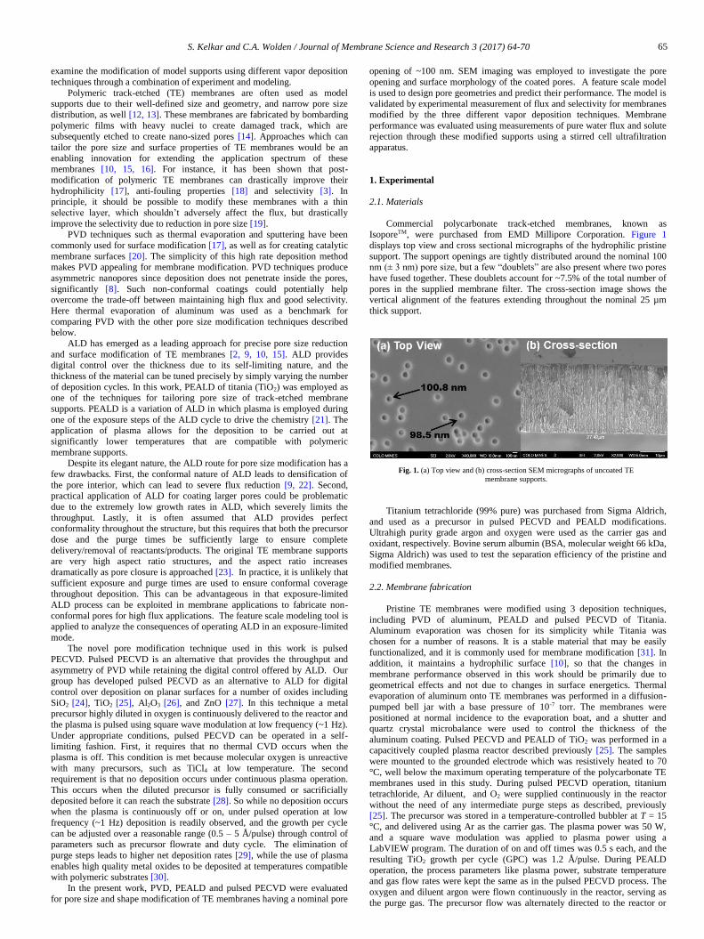
Commercial polycarbonate track-etched membranes, known as IsoporeTM, were purchased from EMD Millipore Corporation. Figure 1
displays top view and cross sectional micrographs of the hydrophilic pristine
support. The support openings are tightly distributed around the nominal 100 nm (± 3 nm) pore size, but a few “doublets” are also present where two pores
have fused together. These doublets account for ~7.5% of the total number of
pores in the supplied membrane filter. The cross-section image shows the vertical alignment of the features extending throughout the nominal 25 µm
thick support.
Fig. 1. (a) Top view and (b) cross-section SEM micrographs of uncoated TE
membrane supports.
Titanium tetrachloride (99% pure) was purchased from Sigma Aldrich,
and used as a precursor in pulsed PECVD and PEALD modifications. Ultrahigh purity grade argon and oxygen were used as the carrier gas and
oxidant, respectively. Bovine serum albumin (BSA, molecular weight 66 kDa,
Sigma Aldrich) was used to test the separation efficiency of the pristine and modified membranes.
2.2. Membrane fabrication
Pristine TE membranes were modified using 3 deposition techniques,
including PVD of aluminum, PEALD and pulsed PECVD of Titania. Aluminum evaporation was chosen for its simplicity while Titania was
chosen for a number of reasons. It is a stable material that may be easily
functionalized, and it is commonly used for membrane modification [31]. In
addition, it maintains a hydrophilic surface [10], so that the changes in
membrane performance observed in this work should be primarily due to
geometrical effects and not due to changes in surface energetics. Thermal evaporation of aluminum onto TE membranes was performed in a diffusion-
pumped bell jar with a base pressure of 10-7 torr. The membranes were
positioned at normal incidence to the evaporation boat, and a shutter and quartz crystal microbalance were used to control the thickness of the
aluminum coating. Pulsed PECVD and PEALD of TiO2 was performed in a capacitively coupled plasma reactor described previously [25]. The samples
were mounted to the grounded electrode which was resistively heated to 70
°C, well below the maximum operating temperature of the polycarbonate TE membranes used in this study. During pulsed PECVD operation, titanium
tetrachloride, Ar diluent, and O2 were supplied continuously in the reactor
without the need of any intermediate purge steps as described, previously [25]. The precursor was stored in a temperature-controlled bubbler at T = 15
°C, and delivered using Ar as the carrier gas. The plasma power was 50 W,
and a square wave modulation was applied to plasma power using a
LabVIEW program. The duration of on and off times was 0.5 s each, and the
resulting TiO2 growth per cycle (GPC) was 1.2 Å/pulse. During PEALD
operation, the process parameters like plasma power, substrate temperature and gas flow rates were kept the same as in the pulsed PECVD process. The
oxygen and diluent argon were flown continuously in the reactor, serving as
the purge gas. The precursor flow was alternately directed to the reactor or
65

S. Kelkar and C.A. Wolden / Journal of Membrane Science and Research 3 (2017) 64-70
directly to the vacuum pump through the LabVIEW-controlled solenoid
valves. For modification of TE membranes, the PEALD process employed 17
s purges, a TiCl4 dose time of 8 s, and 6 s of plasma exposure. The desired degree of pore closure in PEALD and pulsed PECVD was achieved by
varying the number of deposition cycles.
2.3. Membrane characterization
Variable angle spectroscopic ellipsometry (VASE, J. A. Woollam WVASE32) was employed to measure the thickness of the pulsed PECVD
and PEALD TiO2 coatings, whereas the thickness of the Al coating was
determined using profilometry. Field emission scanning electron microscopy (FESEM) (JEOL JSM-7000 F) was used to study the surface morphology of
the modified TE membranes. PEALD- and pulsed PECVD- modified TE
membranes were sputter-coated with a thin layer of gold before FESEM imaging to reduce charging, whereas no such coating was required for the Al-
coated samples. The pure water flux of PVD-, PEALD-, and pulsed PECVD-
modified TE membranes was measured using a stirred ultrafiltration cell (Amicon, Millipore Co.) under 10 psi overhead pressure, and the resulting
flux is reported normalized to the flux of unmodified TE membranes. BSA
was used to determine the solute rejection using a 1 g/L solution prepared in a phosphate buffered saline to maintain the pH at 7.4. During solute rejection
measurements, the retentate solution was continuously stirred at 400 rpm
using a magnetic stirrer. The concentration of BSA in the filtrate was determined by measuring the absorbance values at 280 nm with a Cary 5G
UV-Vis-NIR spectrophotometer.
3. Design and analysis of asymmetric pores
Transport properties of nanopores are closely linked to their geometry. As mentioned earlier, the use of plan view microscopy to characterize the
pore size of modified membranes can have limitations. This is illustrated in
Figure 2, which compares a plan view micrograph, a cross-section micrograph, and a feature scale simulation of silicon wafers patterned with
~125 nm contact holes and modified by pulsed PECVD of alumina. Patterned
wafers were used as surrogates to enable cross-sectional imaging, which is very difficult to achieve from polymeric TE supports. The plan view image
(see Figure 2a) suggests that the average pore opening is ~ 30 nm. However,
the cross-sectional image of the nanopore (see Figure 2b) reveals that the minimum pore opening is much smaller, approximately 10 nm. When these
pores are coated there is significant curvature as the pore is closed, and with
plan view imaging it is difficult, if not impossible, to focus on the position of the minimum pore opening.
In order to engineer the membrane performance, it is imperative to be
able to predict the geometry of the modified pores. Though seldom applied in membrane modification, the microelectronics community has employed
feature scale models for decades to understand and control the deposition of
films on non-planar substrates [32-35]. Recently, we developed a feature scale model that can be used to simulate PVD, ALD, and the transient growth
modes that contribute to deposition in pulsed PECVD [36]. The model
employs a diffusion reaction framework, in which steady state deposition is
modeled based on surface reaction probability (γ), with PVD (γ =1) and ALD
(γ→0) representing the two limits. Pulsed PECVD is a transient deposition process that involves two growth
modes as discussed previously [28]. The first growth mode is analogous to
ALD. During the plasma off state, the precursor adsorbs on the substrate surface, and these adsorbed molecules then react with oxygen radicals during
the plasma on step to contribute to conformal film growth. The second growth
mode is due to reactive species that are formed at plasma ignition, and then deposit with near unity sticking probability (γ =1) in a manner analogous to
PVD. To capture the two growth modes of pulsed PECVD, the model simply
alternates between conditions used to simulate ALD and PVD, using the single adjustable parameter ‘R’, which is the ratio of the PVD growth
component to the ALD growth component. This value can be determined
experimentally using the GPC values measured for both PEALD and pulsed PECVD. For example, if the PEALD GPC is 1 Å/cycle and the pulsed
PECVD rate is 2 Å/cycle then R = 1, which means there are equal
contributions from both growth modes. This model has been validated for both cylindrical pores and Cartesian trenches, with Fig. 2c providing further
validation of its capabilities. The nanopore geometries predicted by the
feature scale model are then employed to predict pure water flux using COMSOL by solving the Navier-Stokes equations for pressure driven flow.
Precursor diffusion limitations can occur while coating very high aspect
ratio features. The feature scale model utilized in this work accounts for exposure limitations that can limit the extent of deposition in high aspect ratio
features in both ALD and pulsed PECVD. For a given precursor exposure,
there is a critical aspect ratio (a*) that can be coated conformally during ALD, and its value can be determined from the scaling relationships developed by
Gordon and co-workers [23]. In the model, the local aspect ratio (a(z, t)) is
calculated as deposition proceeds, and once the local aspect ratio exceeds a*, no further ALD growth is allowed at that position.
One utility of this model is that it can be used to design and analyze the
performance of membrane supports modified by vapor deposition. Fig. 3 compares simulated profiles of 100 nm diameter nanopores modified by
ALD, pulsed PECVD at R = 1, and PVD. The white area represents the
material deposited, whereas the black region represents the surrounding gas phase. These simulations were performed using cylindrical pores with an
initial opening of 100 nm, and in each case deposition was allowed to proceed
until the minimum pore opening was reduced to 20 nm. Fig. 3a shows an ALD-modified pore assuming no exposure limitations, which is perfectly
conformal and results in densification of the underlying support. The other
extreme, Fig. 3c, shows the feature predicted for an ideal PVD process with unity sticking coefficient. Very little deposition is observed within the feature,
creating a highly asymmetric pore structure that would be ideal for membrane
applications. A drawback of this technique is that it requires considerably more deposition to achieve the same degree of pore closure. Finally, Fig. 3b
shows the simulation for pulsed PECVD at R = 1, in which the contributions
of the two growth modes are equal. The pore closure is asymmetric reflecting the benefits of PVD, but the total amount of material required is closer to the
ALD case.
Fig. 2. (a) Top view SEM micrograph of nanopores fabricated using pulsed PECVD; (b) Cross-section SEM of a nanopore; (c) model prediction of the nanopore geometry using the
simulation procedure described in this work.
66

S. Kelkar and C.A. Wolden / Journal of Membrane Science and Research 3 (2017) 64-70
Fig. 3. Simulated deposition profiles on 100 nm features coated by (a) ALD, (b) pulsed PECVD, and (c) PVD for a final pore opening of 20 nm.
Fig. 4. The left panel displays top view micrographs of TE membranes modified by PVD of aluminum (a-c), PEALD of TiO2 (d-f), and pulsed PECVD of TiO2 (g-i) as a function of
planar film thickness. The right panel displays the corresponding feature scale simulation of the resulting geometries noting the minimum pore diameter for these 9 cases.
In the results below, the feature scale model is used to simulate the
nanopore geometries formed by vapor deposition on 100 nm diameter isopore supports. Membranes coated by aluminum evaporation employed the PVD
simulation described above. The pore geometry of the TE membranes modified by PEALD was simulated by superimposing precursor diffusion
limitations on the ideal ALD case shown in Fig. 3a. The critical aspect ratio
during these depositions was estimated to be around a* = 36, based on the 8 s TiCl4 exposure. This means that deposition initially extends ~3.6 µm into the
25 µm pore, and this depth will continue to decrease as the pore shrinks.
The model parameters for pulsed PECVD reflected the experimental
conditions. Based on the TiCl4 exposure provided during the ½ second plasma
off step, a critical aspect ratio of a*= 8.2 was estimated. Again, this implies
that initially the ALD growth component extends 820 nm into the pore, and this value diminishes as growth proceeds. Note that this value of a*
represents an upper limit, and the simulations were not significantly sensitive
to this parameter. Using identical precursor doses the measured GPC for PEALD and pulsed PECVD were 0.56 Å/cycle and 1.2 Å/cycle, respectively.
Hence, the corresponding PVD/ALD ratio or R was determined to be ~1. The
net planar growth rate in pulsed PECVD was 7.2 nm/min, over 35 times faster than the 0.2 nm/min obtained with the PEALD process.
4. Results and discussion
The left panel of Figure 4 shows the top view SEM micrographs of TE membranes modified by different vapor deposition techniques employed in
this work as a function of thickness. The labels report the planar thickness of
the deposited film, and the arrows in the micrographs point out the apparent
diameter of the resulting pore openings. The right panel of Fig. 4 displays
simulated cross-sections of the resulting pore geometries at these same
conditions, and the labels indicate the minimum pore diameter under these conditions. The specific conditions were chosen to provide examples of low,
intermediate, and high degrees of pore closure for each deposition technique.
There are a number of important observations to take away from this
figure. First, the micrographs confirm that the amount of deposited material required to achieve the same degree of pore closure varies by techniques in
the descending order of PVD > pulsed PECVD > PEALD, as predicted in Fig. 3. For example, to reduce the minimum pore diameter to 40 nm requires 30
nm of deposition by PEALD, 36 nm of pulsed PECVD, and 58 nm of PVD.
Moreover, the differences become more pronounced as the degree of pore closure increases. Second, this figure confirms the limitations of using top
view microscopy for evaluation of pore closure. At low levels of deposition
(see Figure 4a/d/g), the pore diameter estimated from SEM images is in good
agreement with model predictions. However, the disparity between these
values gets worst with increasing deposition. At a high degree of pore closure
(see Figure 4c/f/i) the SEM image overestimates the minimum pore size by a factor of ~2 for all three deposition techniques. Finally, it is observed that the
morphology of the three films are quite different. In the case of evaporated
aluminum, the coatings are rough, reflecting the Volmer–Weber growth mode that results in a polycrystalline morphology [37]. These films would fall into
zone 1 of the Thornton diagram [38], which consists of columnar growth with
voided defects due to atomic shadowing. The diffusion-reaction model does not capture these features, but as shown below it has a significant impact on
membrane performance.
At low deposition thickness, both pulsed PECVD and PEALD display a smooth surface morphology. However, at a coating thicknesses > 30 nm the
PEALD becomes rough and appears to become polycrystalline (see Fig. 4f),
whereas the pulsed PECVD film remains smooth and amorphous. This behavior reflects the unique feature of TiO2. It has been observed that ALD
initially produces amorphous TiO2, but there is a critical thickness at which
point the film transforms into the polycrystalline anatase phase. The exact
value of this transition depends on deposition conditions [39-41]. Due to its
slower growth rate, the PEALD films likely have better quality and transform
from amorphous to polycrystalline at a lower thickness than the pulsed PECVD films.
Figure 5 compares the membrane flux as a function of the planar
67

S. Kelkar and C.A. Wolden / Journal of Membrane Science and Research 3 (2017) 64-70
thickness for the three different modification methods. As could be observed,
uncoated supports had a pure water flux (PWF) of 7360±294 L/(m2.h.bar).
Relative flux is defined as the pure water flux (PWF) of a coated TE membrane normalized with respect to that of the uncoated TE membranes.
The solid black lines represent the flux predicted by the feature scale model,
which were obtained by exporting the simulated geometries of the modified pores into another COMSOL module and modeling Hagen-Poiseuille flow
through the resulting pores. In addition, the flux expected from a perfectly
conformal coated pore is included as the dashed red lines for comparison. The flux of a conformally coated membrane is predicted to drop, sharply, due to
densification of the pores. In contrast, the techniques used in this work that
lead to asymmetric pore closure allow the flux to remain largely unchanged until the pore diameter is reduced <20 nm.
Figure 5a shows the results for the PVD-modified membrane. There is
generally good agreement between the measured and predicted flux. However, there is significant scatter in the data and poor reproducibility,
which is attributed to the roughness and morphological instabilities associated
with the columnar growth mode discussed above. As expected, the asymmetric pore geometry allows the flux of PVD-modified supports to
remain nominally unchanged up to a thickness of 75 nm. The flux of the
membranes drops to 0 only for coating thicknesses >125 nm. In the range of 75 -125 nm, where pore closure is approached, there is great variability with
similarly coated pores delivering high flux or no flux. This makes PVD
unsuitable for nanoscale control of performance. In contrast, both PEALD and pulsed PECVD provided excellent
reproducibility and control over the degree of pore closure. In the case of
PEALD (see Figure 5b), the flux declines approximately linearly with the
amount of TiO2 deposited, and the agreement with the model is excellent. The
measured flux is slightly greater than model predictions in the transition
regime, and there is a very small but non-negligible flow measured for membrane modified with >50 nm of material, where pore closure is predicted.
Both of these minor deviations are attributed to the presence of the doublets
(see Figure 1a) that are not accounted for in the model. The stark contrast between the conformal prediction and the observed performance highlights
the importance of operating ALD in the exposure limited regime in order to
maintain significant flux. Pulsed PECVD (see Figure 5c) combines the asymmetry of the PVD
modification with the control and reproducibility of ALD. The flux is
unchanged up to 30 nm of deposited material, and then it begins to attenuate as pore closure is reached. The flux drop off in this regime is steep, and the
digital control and smooth morphology enables precise control over
membrane properties. The amount of material for complete pore closure is just slightly greater than PEALD, but less than half the material required by
PVD. For all three deposition techniques, the experimentally measured flux is
well captured by the model, validating its utility for this application. The selectivity of the modified membranes was evaluated using bovine
serum albumin (BSA) as a model solute in a stirred ultrafiltration cell. These
results were not significantly impacted by protein adsorption as it was found that both the pristine TE membranes and all of the modified supports
exhibited excellent anti-fouling characteristics. The membranes exhibited a
static BSA adsorption value <10 µg/cm2 after immersion in a 1 g/L BSA solution for 24 hours. This is attributed to the hydrophilic nature of the
original TE membranes.
Fig. 5. Comparison of experimentally measured (points) and predicted flux (black lines) as a function of deposition thickness for TE membranes modified by (a) aluminum PVD, (b)
PEALD of titania, and (c) pulsed PECVD of titania. The dashed red line is the prediction for perfectly conformal modification.
68

S. Kelkar and C.A. Wolden / Journal of Membrane Science and Research 3 (2017) 64-70
Fig. 6. Solute rejection and predicted flux as a function of film thickness for (a) PVD-modified membranes; (b) PEALD-modified membranes and (c) Pulsed PECVD-modified
membranes. Circled values indicate membranes that displayed the best combination of flux and selectivity for each technique as discussed in the text.
The hydrophilicity, and hence the anti-fouling nature, of the membranes
is maintained even after modification. Hydrophilicity of the membranes was tracked using a simple home-made contact angle measurement apparatus [42].
The contact angle of the pristine TE membranes, TiO2-modified membranes,
and Al-modified membranes were 44±3°, 52±5°, and 65±7°, respectively. It should be noted that the TiO2-modified TE membranes were initially very
hydrophilic (θ ~ 0°). However, the hydrophilicity is quickly lost upon
exposure to the atmosphere due to hydrocarbon contamination. Figure 6 compares the solute rejection and the modeled flux of the
modified TE membranes as a function of the planar thickness of the deposited
coatings. BSA (molecular size ~ 7 nm) was used as the model solute. Figure 6a displays the solute rejection of the PVD-modified supports. Solute
rejection scales linearly with thickness, and reaches a maximum of ~70% only
after the evaporation of 200 nm of aluminum, at which point the flux is negligible. As with measurement of flux, the solute rejection data is also very
noisy, reflecting the rough morphology of these layers. The optimal value for
PVD modification was achieved at 100 nm of coating thickness. In this membrane, the solute rejection was just 44%, and though the model predicts
45% of the original flux the measured value was just 29%. With the PVD-
modified supports >50% solute rejection was only achieved when the flux approaches zero.
In the case of PEALD, the solute rejection was negligible (<10 %) and
unchanged through 20 nm of deposition. The rejection then increases linearly between 20 and 50 nm, where the rejection saturates at ~80%. At this point,
the 100 nm pores are completely closed, and the remaining flux of BSA
solutes is due to doublets. Optimal performance was achieved with the membrane coated with 39 nm of TiO2 film. At this point, the 50% solute
rejection was achieved while retaining 40% of the initial membrane flux. So,
although the control and reproducibility was significantly improved relative to PVD modification, only modest improvements in selectivity/flux were
obtained.
In contrast to PEALD, the retention behavior of membranes modified by pulsed PECVD exhibit step function behavior as shown in Fig. 6c. For <25
nm of TiO2 deposition, the membranes display negligible solute rejection
(~7%) that is unchanged from the uncoated support. The rejection level increases sharply between 40-50 nm of deposited material to a value of ~75%,
that remains essentially unchanged with additional coating and is attributed to
the presence of doublets. The membrane modified by 48 nm of TiO2 deposition retained ~70% of the original flux, and the BSA solute rejection
approaches the saturation threshold (~ 75%). This is a tremendous
improvement over both PVD and PEALD modification. The window for optimal performance is narrow, and thus the digital control over deposition
provided by pulsed PECVD is important in achieving this level of
performance.
5. Conclusions
Track-etched membrane supports were modified using PVD of
aluminum, PEALD and pulsed PECVD of Titania. A feature scale model was used to design the resulting pore geometries, successfully predicting the flux
behavior of modified membranes. PVD modification results created highly
asymmetric nanopores that in principle should lead to high flux and good selectivity. However, PVD requires much more material for comparable pore
69
S. Kelkar and C.A. Wolden / Journal of Membrane Science and Research 3 (2017) 64-70
closure, and the rough, columnar growth morphology limits reproducibility
and solute retention. PEALD was shown to deliver precise pore size
reduction, requiring significantly less film deposition in comparison to PVD. By operating in a precursor exposure limited regime, the PEALD-modified
membranes exhibited higher flux than would be achieved with perfectly
conformal deposition. However, both flux and retention scale linearly with deposition thickness, limiting the ability to simultaneously optimize both
quantities. Pulsed PECVD produced asymmetric pores characteristic of PVD
while displaying the precision and reproducibility of PEALD. Both flux and retention display step function behavior with respect to thickness, creating a
small window to overcome the flux/selectivity tradeoff. The digital control of
pulsed PECVD enabled access to this region, achieving maximum solute rejection while retaining 70% of the original flux.
6. Acknowledgements
The authors gratefully acknowledge the financial support from the National Science Foundation through award CBET-1033203.
7. References
[1] M. Pan, C. Cooper, Y.S. Lin, G.Y. Meng, CVD modification and vapor gas
separation properties of nanoporous alumina membranes, J. Membr. Sci. 158 (1999)
235-241.
[2] F. Li, Y. Yang, Y. Fan, W. Xing, Y. Wang, Modification of ceramic membranes for
pore structure tailoring: The atomic layer deposition route, J. Membr. Sci. 397
(2012) 17-23.
[3] A. Asatekin, K.K. Gleason, Polymeric nanopore membranes for hydrophobicity-
based separations by conformal initiated chemical vapor deposition, Nano Lett. 11
(2011) 677-686.
[4] T. Ito, T. Hioki, T. Yamaguchi, T. Shinbo, S.-I. Nakao, S. Kimura, Development of
a molecular recognition ion gating membrane and estimation of its pore size control,
J. Am. Chem. Soc. 124 (2002) 7840-7846.
[5] K.B. Jirage, J.C. Hulteen, C.R. Martin, Nanotubule-based molecular-filtration
membranes, Science 278 (1997) 655-658.
[6] Y.-Y. Li, T. Nomura, A. Sakoda, M. Suzuki, Fabrication of carbon coated ceramic
membranes by pyrolysis of methane using a modified chemical vapor deposition
apparatus, J. Membr. Sci. 197 (2002) 23-35.
[7] S. Araki, N. Mohri, Y. Yoshimitsu, Y. Miyake, Synthesis, characterization and gas
permeation properties of a silica membrane prepared by high-pressure chemical
vapor deposition, J. Membr. Sci. 290 (2007) 138-145.
[8] K. Grigoras, V.-M. Airaksinen, S. Franssila, Coating of nanoporous membranes:
atomic layer deposition versus sputtering, J. Nanoscience Nanotechnol. 9 (2009)
3763-3770.
[9] F. Li, L. Li, X. Liao, Y. Wang, Precise pore size tuning and surface modifications of
polymeric membranes using the atomic layer deposition technique, J. Membr. Sci.
385 (2011) 1-9.
[10] Q. Wang, X. Wang, Z. Wang, J. Huang, Y. Wang, PVDF membranes with
simultaneously enhanced permeability and selectivity by breaking the tradeoff
effect via atomic layer deposition of TiO2, J. Membr. Sci. 442 (2013) 57-64.
[11] A.W. Ott, J.W. Klaus, J.M. Johnson, S.M. George, K.C. McCarley, J.D. Way,
Modification of porous alumina membranes using Al2O3 atomic layer controlled
deposition, Chem. Mater. 9 (1997) 707-714.
[12] W. Deen, Hindered transport of large molecules in liquid‐filled pores, AIChE J. 33
(1987) 1409-1425.
[13] W. Deen, M. Bohrer, N. Epstein, Effects of molecular size and configuration on
diffusion in microporous membranes, AIChE J. 27 (1981) 952-959.
[14] P. Apel, Track etching technique in membrane technology, Rad. Meas. 34 (2001)
559-566.
[15] Q. Xu, J. Yang, J. Dai, Y. Yang, X. Chen, Y. Wang, Hydrophilization of porous
polypropylene membranes by atomic layer deposition of TiO2 for simultaneously
improved permeability and selectivity, J. Membr. Sci. 448 (2013) 215-222.
[16] K.C. Khulbe, C. Feng, T. Matsuura, The art of surface modification of synthetic
polymeric membranes, J. Appl. Polymer. Sci. 115 (2010) 855-895.
[17] M. Tavakolmoghadam, T. Mohammadi, M. Hemmati, F. Naeimpour, Surface
modification of PVDF membranes by sputtered TiO2: fouling reduction potential in
membrane bioreactors, Desal. Water Treat. (2014) 1-11.
[18] C.Y. Tang, Y.-N. Kwon, J.O. Leckie, Effect of membrane chemistry and coating
layer on physiochemical properties of thin film composite polyamide RO and NF
membranes: II. Membrane physiochemical properties and their dependence on
polyamide and coating layers, Desalination 242 (2009) 168-182.
[19] M. Ulbricht, Advanced functional polymer membranes, Polymer 47 (2006) 2217-
2262.
[20] S. Cha, W. Lee, Performance of proton exchange membrane fuel cell electrodes
prepared by direct deposition of ultrathin platinum on the membrane surface, J.
Electrochem. Soc. 146 (1999) 4055-4060.
[21] H.B. Profijt, S.E. Potts, M.C.M. van de Sanden, W.M.M. Kessels, Plasma-assisted
atomic layer deposition: Basics, opportunities, and challenges, J. Vac. Sci. Technol.
A 29 (2011) 050801.
[22] B.A. McCool, W.J. Desisto, Self‐limited pore size reduction of mesoporous silica
membranes via pyridine‐catalyzed silicon dioxide ALD, Chem. Vap. Deposit. 10
(2004) 190-194.
[23] R.G. Gordon, D. Hausmann, E. Kim, J. Shepard, A kinetic model for step coverage
by atomic layer deposition in narrow holes or trenches, Chem. Vap. Deposit. 9
(2003) 73-78.
[24] P.C. Rowlette, M. Canon, C.A. Wolden, Digital control of SiO2 film deposition at
room remperature, J. Phys. Chem. C 113 (2009) 6906-6909.
[25] N.G. Kubala, P.C. Rowlette, C.A. Wolden, Self-limiting deposition of anatase TiO2
at low temperature by pulsed PECVD, Electrochem. Solid-State Lett. 12 (2009)
H259-H262.
[26] S.F. Szymanski, P. Rowlette, C.A. Wolden, Self-limiting deposition of aluminum
oxide thin films by pulsed plasma-enhanced chemical vapor deposition, J. Vac. Sci.
Technol. A 26 (2008) 1079-1084.
[27] P.C. Rowlette, C.G. Allen, O.B. Bromley, C.A. Wolden, Self-limiting deposition of
semiconducting ZnO by pulsed plasma-enhanced chemical vapor deposition, J. Vac.
Sci. Technol. A 27 (2009) 761-766.
[28] M.T. Seman, D.N. Richards, P. Rowlette, C.A. Wolden, An analysis of the
deposition mechanisms involved during self‐limiting growth of aluminum oxide by
pulsed PECVD, Chem. Vap. Deposit. 14 (2008) 296-302.
[29] M.T. Seman, D.N. Richards, P.C. Rowlette, N.G. Kubala, C.A. Wolden,
Enhancement of metal oxide deposition rate and quality using pulsed plasma-
enhanced chemical vapor deposition at low frequency, J. Vac. Sci. Technol. A 26
(2008) 1213-1217.
[30] R.P. Patel, C.A. Wolden, Defect analysis and mechanical performance of plasma-
deposited thin films on flexible polycarbonate substrates, Appl. Surf. Sci. 268
(2013) 416-424.
[31] Y. Jun, H. Zarrin, M. Fowler, Z. Chen, Functionalized titania nanotube composite
membranes for high temperature proton exchange membrane fuel cells, Int. J.
Hydrogen Energy 36 (2011) 6073-6081.
[32] S. Ganguli, S.P. Costello, W.N. Gill, Theory of free boundary step coverage in
chemical vapor deposition, Ind. Eng. Chem. Res. 34 (1995) 3380-3391.
[33] M.K. Jain, T.S. Cale, T.H. Gandy, Comparison of LPCVD film conformalities
predicted by ballistic transport‐reaction and continuum diffusion‐reaction models, J.
Electrochem. Soc. 140 (1993) 242-247.
[34] T. Cale, T. Gandy, G. Raupp, A fundamental feature scale model for low pressure
deposition processes, J. Vac. Sci. Technol. A 9 (1991) 524-529.
[35] M. Cooke, G. Harris, Monte Carlo simulation of thin‐film deposition in a
rectangular groove, J. Vac. Sci. Technol. A 7 (1989) 3217-3221.
[36] S.S. Kelkar, C.A. Wolden, Feature scale modeling of pulsed plasma-enhanced
chemical vapor deposition, J. Vac. Sci. Technol. B 32 (2014) 052001.
[37] S.C. Seel, C.V. Thompson, S.J. Hearne, J.A. Floro, Tensile stress evolution during
deposition of Volmer–Weber thin films, J. Appl. Phys. 88 (2000) 7079-7088.
[38] J.A. Thornton, The microstructure of sputter-deposited coatings, J. Vac. Sci.
Technol. A 4 (1986) 3059-3065.
[39] H.-E. Cheng, C.-C. Chen, Morphological and photoelectrochemical properties of
ALD TiO2 films, J. Electrochem. Soc. 155 (2008) D604-D607.
[40] M. Ritala, M. Leskelä, E. Nykänen, P. Soininen, L. Niinistö, Growth of titanium
dioxide thin films by atomic layer epitaxy, Thin Solid Films 225 (1993) 288-295.
[41] N.G. Kubala, P.C. Rowlette, C.A. Wolden, Self-limiting deposition of anatase TiO2
at low temperature by pulsed PECVD, Electrochem. Solid-State Lett. 12 (2009)
H259-H262.
[42] S.S. Kelkar, D. Chiavetta, C.A. Wolden, Formation of octadecyltrichlorosilane
(OTS) self-assembled monolayers on amorphous alumina, Appl. Surf. Sci. 282
(2013) 291-296.
70