evaluation of the sfsk-ook integrated plc-vlc system under
TRANSCRIPT
Evaluation of the SFSK-OOK Integrated PLC-VLCSystem Under the Influence of Sunlight
S. M. Nlom, K. Ouahada, A. R. Ndjiongue and H. C. FerreiraCentre for Telecommunication (CFT)
School of Electrical and Electronic Engineering Science,University of JohannesburgP.O. Box 524, Auckland Park, 2006, Johannesburg, South Africa.
Email:{smartin,kouahada,arrichard,hcferreira}@uj.ac.za
Abstract—With the widespread of light emitting diodes (LEDs)as a primary source of illumination, visible light communication(VLC) offers a lot of potentials by providing both resourcesand energy saving advantages. This paper presents a practicalimplementation of an integration of Power Line Communication(PLC) and VLC. The system uses spread frequency shift keying(S-FSK) and on-off keying (OOK) in the PLC and VLC channelrespectively. The system is of low complexity, low cost and ded-icated to enhance low data rate application of PLC technology.The practical design is compatible with the European Committeefor Electrotechnical Standardization (CENELEC) band A andthe test are done on a Chinese home environment where theElectric Power Research Institute (EPRI) specifies a 3 kHz to500 kHz band. Results illustrating the effect of sunlight on thissystem are presented.
keywords—Narrowband PLC, VLC, S-FSK, PLC-VLC,OOK, Hardware implementation
I. INTRODUCTION
Integrated power line communication (PLC) and visiblelight communication (VLC) systems, onward referred to asPLC-VLC, has recently raised a considerate amount of atten-tion [1]–[6]. This is primarily as a result of the ubiquitousnature and characteristic found in such a combination. Thepower line cables already used to distribute electricity, isalso widely used by PLC technology as a communicationmedium. The lighting system infrastructure is gradually usinglight emitting diodes (LED) because of their advantage overincandescent light bulbs. In VLC, the use of LED in light-ing systems is exploited into providing ubiquitous networksfor communication. VLC is an intensity modulation/directdetection (IM/DD) based communication technology whichadds a DC-voltage to a modulated signal to provide bothluminance and information transmission through LEDs. PLC-VLC integration therefore both poses communication, energydistribution and illumination capabilities. In addition to that,the presence of their respective infrastructures makes theirdeployment economically viable, feasible and beneficial. VLCtechnology provides PLC with the ability to transform itssignal into a wireless one [1]. Furthermore, VLC providesPLC with an access to a wide spectrum (380nm-780nm) forcommunication.
The first idea of integrating PLC and VLC was introducedin [2]. This implemented a single carrier binary phase shift(SC-BPSK) to convey low data rate information. Orthogonal
frequency modulation (OFDM) was further used to improvethe spectral efficiency of the PLC-VLC integration [1]. TheIEEE 802.15.7 [7] is a standard which defines a PHY layersuitable for VLC. This suggests a set of modulation scheme fordifferent scenarios and application based on data-requirement.On-off keying (OOK) modulation is the simplest techniqueproposed in [7]. OOK, with its low complexity and cost istherefore the best available scheme utilised for VLC systems.In the current state of research involving PLC and VLCintegration, a lot of attention is given on broadband PLC andVLC which uses multi-carrier modulation technique. This issuccessfully being used in broadband broadcasting systems[3]. Such applications where PLC is used as backbone ofthe communication infrastructure are dedicated to high speeddata transmission and are of high complexity and cost [8].Furthermore, few attention have been placed on narrowbandPLC (NBPLC) integration with VLC systems. VLC can beuseful in smart home applications [9] whose data requirementsare not demanding as in broadband applications. Few practical-orientated works are also currently available to support thePLC-VLC integration. Spread frequency shift keying (S-FSK)[10] is a modulation which combines advantages of FSK withthose of spread spectrum systems which low-complexity andnarrowband interference immunity respectively [11]. Spread-FSK has eventually been adopted over PLC applications andthe IEC 61334-5-1 standard.
The authors in [5] have already proposed a low-complexityPLC-VLC interface between the two technologies. In thispaper, we further our development and propose a fully fledge,low-complexity, low-cost and analyse the performance of aPLC-VLC communication system for low-data rate applica-tions utilising S-FSK in PLC and OOK in VLC. Complexity ofthe system is minimized through the use of simple modulationtechniques and further cost of the system is achieved withlow cost implementation of the subsystem components such aspower supply and PLC coupling. The hardware implementedwas safely tested in a live environment at a Beijing apartment.Compliance with EN 5006-1 and IEC 61334-5-1 standardsare applied to the prototype design which is operated in theCENELEC-A band. The effect of sunlight radiance as a majorsource of noise in this system is measured by the luminanceat the receiver. This is performed at different instance of theday in order to show the variance of the noise disturbance.
The rest of this paper is organised as follows. Section IIgives an overall system description. This is supported by atheoretical background in Section III. Section IV describes theimplemented hardware in this study. Results and experimentalanalysis of Section V precedes the conclusion in Section VI.
II. SYSTEM DESCRIPTION
PLC-VLC (FSK-OOK) MODULE
FSKPLC MODEM
PLC CHANNEL VLC RECEIVER DATA
DATA
NRZ-OOK
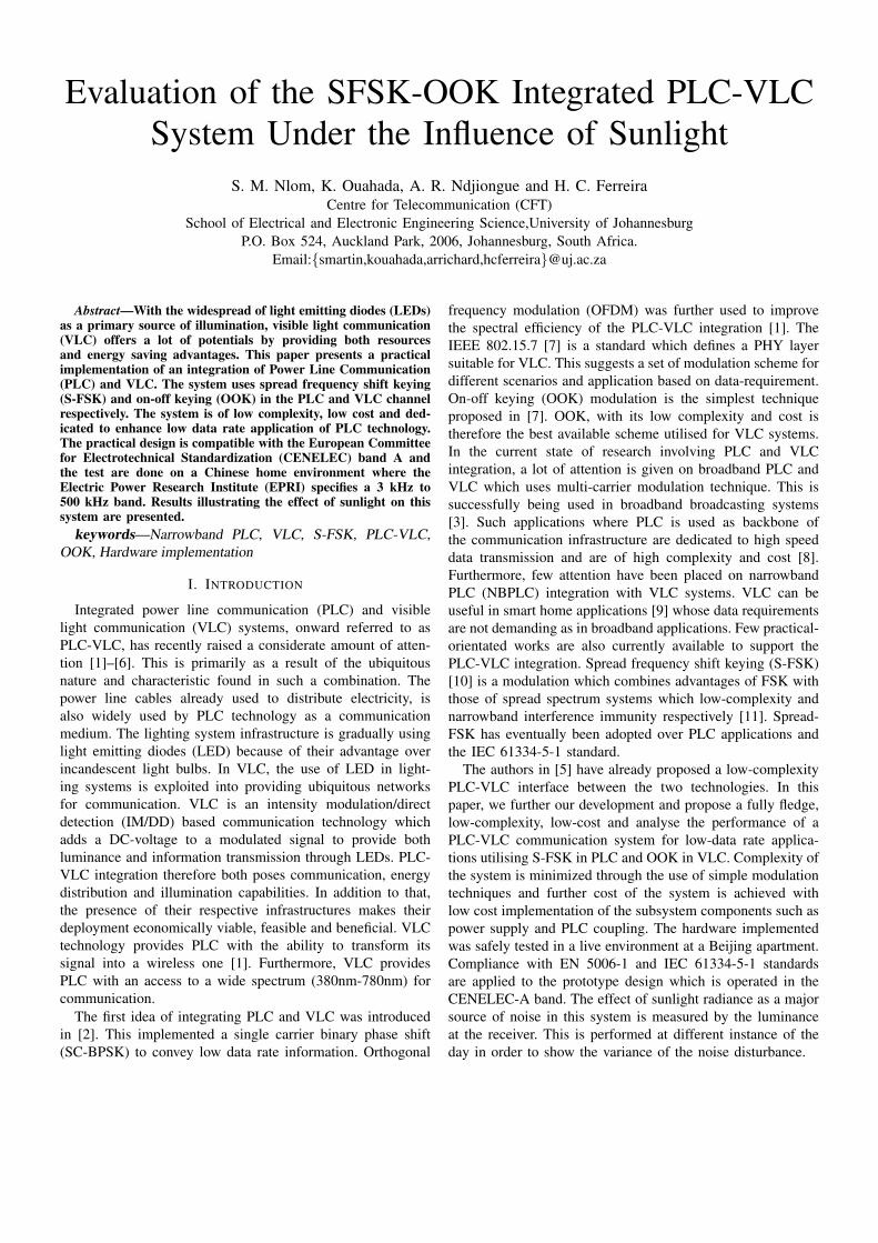
Fig. 1. Overview of system under study
In this section, an overview and brief introduction to the lowcomplexity, low cost integrated PLC-VLC system to enhancelow-data rate application is given.
The system presented here is shown in Fig. 1 and usesthe indoor 230V/50Hz power line network. Transmitted in-formation bits are processed through a PLC modem whichis responsible to convey the information via the power linecables. The PLC modem using S-FSK scheme, modulates,amplifies and superimposes the data signal on the 50Hz ACsignal. The data is then conveyed through the power line cablesto a receiving point. At the receiver, this information carryingsignal is decoupled from the AC line. It is then demodulatedand converted to an OOK signal which is then used todrive the LED luminary. The PLC-VLC module effectivelyconverts the electrical signal of the PLC to an optical signalwhich is needed in VLC. The information carrying signal istherefore intensely modulated or biased through an LED whichalso provides illumination. This information carrying signal isdirectly detected by a PD in the VLC receiver and the initialdata is recovered.
Being an integrated system, the signal is affected by noisepresent in both PLC and VLC channels. Interference and noiseissues are inherently present in the PLC environment whichis also highly frequency selective and time variant. NBPLCoperating between 3Hz-500kHz [7] has been characterisedby mainly background, impulsive and narrowband noise [12],[13]. VLC is an optical wireless communication and has thelight in free space as channel [6]. Noise in VLC thereforeoriginates from other light sources such as sunlight andincandescent or fluorescent light.
The system presented here targets peer-to-peer and low-datarate applications. This PLC-VLC integration could also befound useful in smart-grid communication such as the smart-home technologies presented in [9].
III. THEORETICAL BACKGROUND
A. Modulation SchemeFrequency shift keying is a modulation scheme which
transmits digital data through shifting of a carrier frequency to
discrete frequencies. Binary FSK (BFSK) being the simplisticform with modulation level M = 2, for transmission of data,mark and space frequencies are chosen to represent 1 and0, respectively. Moreover, BFSK scheme is made coherent byensuring the initial phases for the two signal used are the same.This provides a continuous signal between bits transition andsuperior error performance. Thus in general for a coherentBFSK scheme:
s(t) =
{s1(t) = A cos(2πf0t+ φ) 0 ≤ t ≤ Tb,s2(t) = A cos(2πf1t+ φ) 0 ≤ t ≤ Tb,
(1)
where φ is the initial phase at t = 0 and A is the amplitude.Spread FSK (S-FSK) modulation is a technique employed
on the IEC-61334-5-1 PHY layer which requires |f0 − f1| >10kHz. This adds robustness to the FSK scheme and reducesthe chances of narrowband interference.
On-off keying modulation is the simplest form of amplitudeshift keying. Its selection in our proposed system is tied to itsgood bandwidth efficiency, simplicity and ease of implemen-tation. In OOK, bits are encoded by transmission for a timeT for a bit 1 and not transmitting for the same period whenit is a 0.
In order to implement a IM/DD scheme, VLC requires areal and non-negative signal. Two voltage levels ”0” and ”A”are used in VLC to form a square wave. The mapping in (2) isperformed whereby, the space and mark frequencies representthe voltage levels ”0” and ”A”, respectively. In other words,the FSK modulator’s output corresponds to the input of theOOK modulator.{
s1(t) = A cos(2πf0t+ φ) =⇒ 0,
s2(t) = A cos(2πf1t+ φ) =⇒ A.(2)
B. PLC-VLC Integration
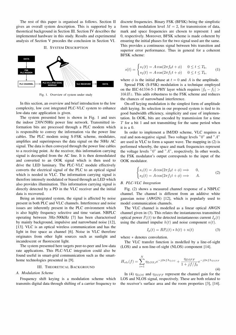
Fig. (2) shows a measured channel response of a NBPLCchannel. The channel is different from an additive whitegaussian noise (AWGN) [12], which is popularly used tomodel communication channels.
The VLC channel is modelled as a linear optical AWGNchannel given in (3). This relates the instantaneous transmittedoptical power Pt(t) to the detected instantaneous current Ip(t)using the channel impulse h(t) and noise component n(t).
Ip(t) = RPt(t) ∗ h(t) + n(t) (3)
where ∗ denotes convolution.The VLC transfer function is modelled by a line-of-sight
(LOS) and a non-line-of-sight (NLOS) component [14].
Hvlc(f) =
N∑i=1
ηLOS,ie−j2πfΛLOS +
ηDIFF1 + jf/f0
e−j2πfΛDIFF
(4)In (4) ηLOS and ηDIFF represent the channel gain for the
LOS and NLOS signal, respectively. These are both related tothe receiver’s surface area and the room properties [3], [14].

ΛLOS and ΛDIFF are signal delays over their respective links,and f0 is the cut-off (3-dB) frequency of the purely diffusechannel.
Fig. 2. Measured spectrum of PLC over CENELEC A-Band
C. Noise and InterferenceThe presented system being an integration of two indepen-
dent communication channels which are cascaded. This willresult in the superposition of their respective noise compo-nents.
The noise model assumed over the NBPLC is a cyclostation-ary additive Gaussian noise with zero mean and its variancesynchronous to the mains AC voltage [12]. This model is madeup of the time dependant instantaneous noise power (5) andfrequency dependant power spectral density (6).
σ̂(t) =
L−1∑l=0
Al|sin (2πt/TAC + θl)|nl (5)
α(f) =a
2exp(−a/|f |) (6)
Equations (5) and (6) make up the variance (7) of the powerline noise [12].
σ2 = σ̂(t)α(f) (7)
In (5), the parameters Al, θl and nl are extracted from ameasured time domain noise measurement.
VLC channel on the other hand, is characterised by thermaland shot noise [2], [6]. Shot noise is as a result of other lightsources and can be modelled by Poisson distribution.
IV. HARDWARE IMPLEMENTATION AND DESCRIPTION
A. FSK-PLC TransmitterThe PLC transmitter implemented is a coherent binary FSK.
Two discrete frequencies are selected within the CENELEC ABand. From the measure channel response of Fig. 2, favourablefrequencies with lesser noise components are located above 30kHz.
Important design steps were applied on the coupling inter-face. This ranges from impedance matching to winding ratiosuggested by previous studies [15] is applied here. Fig. 3shows the designed hardware prototype showing its variousblocks components.
PLC COUPLING
POWER SUPPLY
MODULATOR
POWER AMPLIFIER
DATA INTERFACE
Fig. 3. FSK-PLC Module
B. PLC-VLC Module
The PLC-VLC module’s input is expecting a S-FSK signal.In order to capture this analog signal, a monolithic phaselocked loop (PLL) detector is implemented. Phase locked loopis a common frequency and phase sensitive control circuit usedfor FSK demodulation. The signal originating from the power-line cable has to primarily be captured by a coupling circuit.Different alternatives to circuit coupler unit exist. However, forcost and size constraints, a passive, transformerless couplingcircuit presented in [16] is a viable choice. Fig.4 shows theresponse of the T-shaped band pass filter (coupling circuit)used on the module. This clearly illustrates the bandwidthavailability for the signal reception over the CENELEC A-Band. The module is further equipped with a transient voltagesuppressor (TVS) and a metal oxide varistor (MOV) whichare protective components for both the module and its users.The last section of this module comprises of an led driverimplemented using a MOSFET transistor. The final prototypeof the module is displayed in Fig. 5. The prototype is in lowcost, complexity and power usage. It is operated at 12V andits maximum current is 500 mA which is the peak the supplycan generate. The supply of this modules imposes a constrainton the LED rating which it can drive for data transmissionand illumination.
Fig. 4. Simulation of PLC Coupling implemented on the PLC-VLC module.

Transformerless Power Supply
Transformerless PLC Coupler
LED DriverFSK
Demodulator
Fig. 5. Hardware PLC-VLC Module depicting its low-cost and low-complexity components composition.
C. VLC Subsystem
In VLC systems, LEDs and the photodetectors (PD) aretransmitter and receiver respectively [6]. The VLC subsystemconsist of an LED as transmitter and a PD as receiver. TheLED used is a desk-lamp which consist of a 3W 4 × 8 LEDmatrix. The photo diode used to receive the OOK transmittedsignal was Vishay BPW34. Its sensitivity is suitable enoughfor its purpose as illustrated by its spectral sensitivity shown inFig 6. The receiver implemented here is a simple illustrationsince the VLC receiver is not study on this paper. Furtherinformations can be found in [17], [18].
Fig. 6. Spectral Sensitivity of PD used, showing the highlighted regionnecessary for VLC data detection.
V. EXPERIMENTS AND RESULTS
The set-up used in this section is shown in Fig. 7. TheFSK-PLC module is connected to the mains and interfaceby a signal generator which emulates data information usinga square wave. The modulated signal is then amplified andtransmitted through the power line cable. The S-FSK signalmeasured prior to transmission is displayed in Fig. 8.
The PLC-VLC module described in Section IV abovedetects and drives an LED which conveys the initial data sent.The S-FSK frequencies used in the test were 35 kHz and 70kHz for space and mark frequencies respectively. The opticalsignal is recovered using the VLC receiver. Luminance of the
Fig. 7. Measuring set-up consisting of a signal generator, HANTEK6052BEPC-OSCILLOSCOPE and including the FSK-PLC module + PLC-VLCmodule both connected to the powerline.
1 0 1 0 1 00 1BIT Stream
Digital Signal
S-FSK Signal
Phase continuous
F0
Fig. 8. Measurement of the FSK-PLC Transmission showing the input dataand the modulated signal coupled to the PLC channel.
LED lamp is measured using a TASI8123 digital lux lightmeter at the receiver at different instance of the day. Distancebetween the transmitting PLC-VLC module and the PD VLCreceiver is varied and results shown in Fig. 9. The room usedconsisted of a single window through which sunlight irradi-ance penetrates. The tests are performed during daytime withLOS maintained between the transmitter and VLC receiver.Though the sunlight irradiance is not quantified, its noisecomponent on the NLOS path affects the received signal.Considerable amount of noise is observed on the receiver.This gradually increases with time of the day. By middaya maximum amount is reach. With LOS maintain and theseparation between the transmitter and PD kept below 50 cm,the data is still received with few disturbances. Backgroundnoise with increase in separation and time of the day is alsoobserved. These observations suggests that there is a safemargin of separation that can be obtained at a specific daytime. Further room for investigating the sunlight irradiancein this integrated system has to be done by also consideringthe noise propagation from the PLC channels which will beinvestigated in future works.

Fig. 9. Measured illuminance against distance between the LED transmitterand receiver at different time of the day.
VI. CONCLUSION
This paper presents an integration of Narrowband PLCand VLC technology utilising spread binary FSK and on-offKeying modulations. The system is a low cost, low complexityand low data rate driven solution. The model of the systemis discussed and a hardware implementation of this integratedsystem is presented. Sunlight irradiance is a major source ofnoise on this integration. The effect of sunlight irradiance atfour different time of the day is measured and discussed.
ACKNOWLEDGEMENT
The authors would like to thank the Beijing University ofTechnology (BIT) for the exchange student program whichpermitted the design, implementation and testing of prototypesused in this study and their laboratories.
REFERENCES
[1] T. Komine, S. Haruyama, and M. Nakagawa, “Performance evaluationof narrowband ofdm on integrated system of powerline communicationand visible light communication,” in Proc. IEEE Symposium on WirelessPervasive Computing, 2006, pp. 6–10.
[2] T. Komine and M. Nakagawa, “Integrated system of white led visible-light communication and power-line communication,” Consumer Elec-tronics, IEEE Transactions on, vol. 49, no. 1, pp. 71–79, 2003.
[3] J. Song, W. Ding, F. Yang, H. Yang, B. Yu, and H. Zhang, “An indoorbroadband broadcasting system based on plc and vlc,” Broadcasting,IEEE Transactions on, vol. 61, no. 2, pp. 299–308, 2015.
[4] A. R. Ndjiongue, T. Shongwe, H. C. Ferreira, T. M. N. Ngatched, andA. J. H. Vinck, “Cascaded plc-vlc channel using ofdm and csk tech-niques,” in IEEE Global Communications Conference (GLOBECOM),Dec 2015, pp. 1–6.
[5] A. Ndjiongue, H. C. Ferreira, K. Ouahada, and A. Vinckz, “Low-complexity socpbfsk-ook interface between plc and vlc channels for lowdata rate transmission applications,” in Power Line Communications andits Applications (ISPLC), 2014 18th IEEE International Symposium on.IEEE, 2014, pp. 226–231.
[6] A. R. Ndjiongue, H. C. Ferreira, and T. Ngatched, “Visible lightcommunications (vlc) technology,” Wiley Encyclopedia of Electrical andElectronics Engineering.
[7] “Ieee standard for local and metropolitan area networks–part 15.7: Short-range wireless optical communication using visible light,” IEEE Std802.15.7-2011, pp. 1–309, Sept 2011.
[8] H. Ma, L. Lampe, and S. Hranilovic, “Integration of indoor visible lightand power line communication systems,” in Power Line Communicationsand Its Applications (ISPLC), 17th IEEE International Symposium on,March 2013, pp. 291–296.
[9] S. V. Tiwari, A. Sewaiwar, and Y. H. Chung, “Smart home technologiesusing visible light communication,” in Consumer Electronics (ICCE),IEEE International Conference on, Jan 2015, pp. 379–380.
[10] T. Schaub, “Spread frequency shift keying,” IEEE Transactions onCommunications, vol. 42, no. 234, pp. 1056–1064, Feb 1994.
[11] D. Veronesi, L. Guerrieri, and P. Bisaglia, “Improved spread frequencyshift keying receiver,” in Power Line Communications and Its Appli-cations (ISPLC), IEEE International Symposium on, March 2010, pp.166–171.
[12] H. C. Ferreira, L. Lampe, J. Newbury, and T. G. Swart, Power Line Com-munications: Theory and Applications for Narrowband and BroadbandCommunications over Power Lines. Wiley Online Library, 2010.
[13] M. Katayama, T. Yamazato, and H. Okada, “A mathematical model ofnoise in narrowband power line communication systems,” IEEE Journalon Selected Areas in Communications, vol. 24, no. 7, pp. 1267–1276,July 2006.
[14] J. Grubor, S. Randel, K.-D. Langer, and J. W. Walewski, “Broadbandinformation broadcasting using led-based interior lighting,” Journal ofLightwave technology, vol. 26, no. 24, pp. 3883–3892, 2008.
[15] P. Van Rensburg, H. Ferreira, and A. Snyders, “Coupler winding ratioselection for effective power transfer to a power-line communicationsreceiver,” in Power Line Communications and Its Applications, 2006IEEE International Symposium on, 2006, pp. 290–295.
[16] M. P. Sibanda, P. A. J. Van Rensburg, and H. C. Ferreira, “Passive,transformerless coupling circuitry for narrow-band power-line commu-nications,” in Power Line Communications and Its Applications, 2009.ISPLC 2009. IEEE International Symposium on. IEEE, 2009, pp. 125–130.
[17] Y. Zhao and J. Vongkulbhisal, “Design of visible light communicationreceiver for on-off keying modulation by adaptive minimum-voltagecancelation,” Engineering Journal, vol. 17, no. 4, pp. 125–130, 2013.
[18] I. E. Lee, M. L. Sim, and F. W.-L. Kung, “Performance enhancement ofoutdoor visible-light communication system using selective combiningreceiver,” Optoelectronics, IET, vol. 3, no. 1, pp. 30–39, 2009.