evaluation of tack coating practices for asphalt overlays
TRANSCRIPT
University of Nebraska - LincolnDigitalCommons@University of Nebraska - LincolnNebraska Department of Transportation ResearchReports Nebraska LTAP
4-2017
Evaluation of Tack Coating Practices for AsphaltOverlays in NebraskaSoroosh AmelianUniversity of Nebraska - Lincoln
Yong-Rak KimUniversity of Nebraska - Lincoln, [email protected]
Follow this and additional works at: https://digitalcommons.unl.edu/ndor
Part of the Transportation Engineering Commons
This Article is brought to you for free and open access by the Nebraska LTAP at DigitalCommons@University of Nebraska - Lincoln. It has beenaccepted for inclusion in Nebraska Department of Transportation Research Reports by an authorized administrator of DigitalCommons@University ofNebraska - Lincoln.
Amelian, Soroosh and Kim, Yong-Rak, "Evaluation of Tack Coating Practices for Asphalt Overlays in Nebraska" (2017). NebraskaDepartment of Transportation Research Reports. 199.https://digitalcommons.unl.edu/ndor/199
Soroosh AmelianGraduate Research AssistantDepartment of Civil EngineeringUniversity of Nebraska-Lincoln
“This report was funded in part through grant[s] from the Federal Highway Administration [and Federal Transit Administration], U.S. Department of Transportation. The views and opinions of the authors [or agency] expressed herein do not necessarily state or reflect those of the U.S. Department of Transportation.”
Nebraska Transportation Center262 Prem S. Paul Research Center at Whittier School2200 Vine StreetLincoln, NE 68583-0851(402) 472-0141
Yong-Rak Kim, Ph.D.
Evaluation of Tack Coating Practices for Asphalt Overlays in Nebraska
2017
Nebraska Transportation Center
Final Report26-1121-4033-001 Report SPR-P1(16) M039
ProfessorDepartment of Civil EngineeringUniversity of Nebraska-Lincoln
Evaluation of Tack Coating Practices for Asphalt Overlays in Nebraska
Soroosh Amelian Graduate Research Assistant
Department of Civil Engineering University of Nebraska-Lincoln
and
Yong-Rak Kim, PhD. Professor
Department of Civil Engineering University of Nebraska-Lincoln
A Report on Research Sponsored by
Nebraska Department of Roads
April 2017

i
Technical Report Documentation Page
1. Report No SPR-P1(16) M039
2. Government Accession No. 3. Recipient’s Catalog No.
4. Title and Subtitle
Evaluation of Tack Coating Practices for Asphalt Overlays in Nebraska 5. Report Date April 03, 2017
6. Performing Organization Code
7. Author/s Soroosh Amelian and Yong-Rak Kim
8. Performing Organization Report No. 26-1121-4033-001
9. Performing Organization Name and Address University of Nebraska-Lincoln, Department of Civil Engineering
10. Work Unit No. (TRAIS)
362M Whittier Research Center, Lincoln, NE 68583-0856 11. Contract or Grant No.
12. Sponsoring Organization Name and Address Nebraska Department of Roads 1400 Highway 2, PO Box 94759, Lincoln, NE 68509
13. Type of Report and Period Covered
14. Sponsoring Agency Code
15. Supplementary Notes
16. Abstract The strength of the bond between asphalt layers affects the lifespan of pavement structures. It is also a key factor in preventing major pavement distresses, such as slippage cracking and delamination. This research project evaluates and compares the effectiveness and performance of different tack coating approaches to ensure the proper bond strength is achieved in asphalt concrete (AC) interlayers through an experimental study. Various tack coat materials, including different types of emulsified asphalt and asphalt binders, at multiple application rates and dilution ratios were investigated. In the first part of this study, laboratory-prepared samples were used to evaluate the sensitivity and effectiveness of the direct shear testing (DST) method, which was selected for the characterization of the AC interlayers where different tack coats were treated. Then, emulsified asphalts and binders were applied to a field test section by varying application rates. The DST was performed under a monotonic loading condition at three different testing temperatures. Interlayer shear strengths were used to rank the performance of the tack coats. In addition, cyclic DST was conducted to investigate fatigue behavior of the interlayers treated with different tack coats. The parameters obtained from the monotonic DST were compared with the fatigue DST results. In general, the test results showed superior interlayer performance from CFS-1 and CRS-2P at double application rate (i.e., 0.16 gal/yd2 residual application rate) and CFS-1 at the standard application rate (i.e., 0.08 gal/yd2 residual application rate). Moreover, CRS-2P provided the shortest breaking time among all the emulsified tack coats. With regard to the correlation between the monotonic and cyclic DST results, the maximum shear force showed an acceptable correlation with the fatigue test results, and the interlayer bond energy, which can also be determined using a monotonic DST, is a good (or better) predictor of the fatigue-related shear resistance of the tack coats due to its higher correlation with the fatigue test results.
17. Key Words Asphalt Pavement, Tack Coats, Direct Shear Test, Performance Ranking
18. Distribution Statement
19. Security Classification (of this report) Unclassified
20. Security Classification (of this page) Unclassified
21. No. of Pages 49
22. Price
Form DOT F 1700.7 (8-72) Reproduction of form and completed page is authorized

ii
Table of Contents
Acknowledgements ....................................................................................................................... vii
Disclaimer .................................................................................................................................... viii
Abstract .......................................................................................................................................... ix
CHAPTER 1 INTRODUCTION .................................................................................................... 1
1.1 Research Objectives ...................................................................................................... 3
1.2 Organization of Report .................................................................................................. 3
CHAPTER 2 BACKGROUND ...................................................................................................... 4
2.1 Benefits of Tack Coat Materials .................................................................................... 4
2.2 Types of Tack Coat ........................................................................................................ 4
2.3 Application Rate ............................................................................................................ 4
2.4 Tack Coat Related Distresses ........................................................................................ 5
2.5 Test Methods to Evaluate Bond Strength ...................................................................... 6
CHAPTER 3 MATERIALS, SAMPLE FABRICATION AND TESTING FACILITIES .......... 12
3.1 Tack Coat Materials Selection ..................................................................................... 12
3.2 Application Rates ........................................................................................................ 12
3.3 Testing Facilities .......................................................................................................... 12
3.4 Laboratory-Prepared Samples ..................................................................................... 14
CHAPTER 4 FIELD TEST PLAN ............................................................................................... 17
4.1 Test Section Configuration .......................................................................................... 17
4.2 Tack Coat Distribution ................................................................................................ 17
4.2.1 Emulsion Tack Coats ....................................................................................... 18
4.2.2 Asphalt Binder Tack Coats .............................................................................. 20
4.3 Paving the Test Section ............................................................................................... 22
4.4 Coring Specimens ........................................................................................................ 22
CHAPTER 5 LABORATORY TESTS, RESULTS AND DISSCUSSION ................................ 24
5.1 Monotonic Direct Shear Test ....................................................................................... 24
5.1.1 Laboratory-Prepared Samples .......................................................................... 24
5.1.2 Field Core Samples .......................................................................................... 30
5.2 Cyclic Direct Shear Test .............................................................................................. 37

iii
5.3 Relationship between Monotonic DST and Cyclic (Fatigue) DST ............................. 42
CHAPTER 6 SUMMARAY AND CONCLUSIONS .................................................................. 46
References ..................................................................................................................................... 47

iv
List of Figures
Figure 1-1. Typical tack coat applications. .................................................................................... 1 Figure 2-1. Delamination distress. ................................................................................................. 6 Figure 2-3. Interlayer bond failure modes (Sutanto, 2009). ........................................................... 7 Figure 2-4. NCAT bond strength fixture. ...................................................................................... 8 Figure 2-5. UTEP pull-off testing device (Tashman, 2006). ......................................................... 8 Figure 2-6. Florida DOT shearing apparatus. ................................................................................ 9 Figure 2-7. Torque bond test (Tashman, 2006). ............................................................................ 9 Figure 2-8. Louisiana interlayer shear strength tester (LISST). .................................................. 10 Figure 2-9. Shear fatigue test (Romanoschi, 2001). .................................................................... 11 Figure 2-10. Virginia shear fatigue test fixture (Donovan et al. 2000). ....................................... 11 Figure 3-1. Direct shear fixture. ................................................................................................... 13 Figure 3-2. UTM-25kN testing equipment. ................................................................................. 14 Figure 3-3. Application of tack coat emulsion. ............................................................................ 15 Figure 3-4. Tack coat emulsion: (a) before breaking, (b) after breaking. .................................... 15 Figure 3-5. SGC compacted samples including interlayer. ......................................................... 16 Figure 3-6. 4-in. diameter core samples. ...................................................................................... 16 Figure 4-1. Configuration of field test section. ............................................................................ 17 Figure 4-2. A pad placed on surface of field pavement section. .................................................. 18 Figure 4-3. Dilution of emulsified asphalt. .................................................................................. 19 Figure 4-4. Distributing tack coat emulsion on the section. ........................................................ 19 Figure 4-5. Breaking of tack coat emulsions. .............................................................................. 20 Figure 4-6. Asphalt spray equipment used for binder tack coats. ................................................ 20 Figure 4-7. Distribution of binder tack coats. .............................................................................. 21 Figure 4-8. Schematic view of test section (14 subsections). ...................................................... 21 Figure 4-9. Paving the thin lift on the tack coated surface. ......................................................... 22 Figure 4-10. Marking coring areas out of wheel path. ................................................................. 22 Figure 4-11. Coring 6-in. diameter samples. ............................................................................... 23 Figure 4-12. Cutting samples to prepare laboratory testing specimens. ...................................... 23 Figure 5-1. The effect of sample size on interlayer properties. ................................................... 25 Figure 5-2. Effect of temperature on interlayer maximum shear force. ...................................... 25 Figure 5-3. Effect of normal pressure on shear behavior. ............................................................ 26 Figure 5-4. Effect of tack coat type on interlayer shear strength. ................................................ 27 Figure 5-5. Effect of tack coat type on interlayer tangential modulus. ........................................ 28 Figure 5-6. Effect of application rate on interlayer shear strength. ............................................. 29 Figure 5-7. Emulsion breaking time for SPR mixture. ................................................................ 30 Figure 5-8. Effect of milling on interlayer shear strength. ........................................................... 30 Figure 5-9. Failure surface after DST: (a) sample with milled, (b) sample with non-milled. ..... 31 Figure 5-10. Breaking time of emulsified tack coats. .................................................................. 32

v
Figure 5-11. Interlayer shear strength at 5°C. .............................................................................. 33 Figure 5-12. Interlayer tangential modulus at 5°C. ...................................................................... 33 Figure 5-13. Interlayer shear strength at 25°C. ............................................................................ 34 Figure 5-14. Interlayer tangential modulus at 25°C. .................................................................... 34 Figure 5-15. Interlayer shear strength at 60°C. ............................................................................ 35 Figure 5-16. Interlayer tangential modulus at 60°C. .................................................................... 36 Figure 5-17. Ranking of tack coats based on average normalized value. .................................... 36 Figure 5-18. Cyclic direct test set-up. .......................................................................................... 37 Figure 5-19. A typical data acquisition outcomes from fatigue test. ........................................... 37 Figure 5-20. PSD vs. loading cycles. ........................................................................................... 38 Figure 5-21. PSD Curve fitting based on Francken model. ......................................................... 39 Figure 5-22. Average fatigue results: Criterion 1. ....................................................................... 40 Figure 5-23. Average fatigue results: Criterion 2. ....................................................................... 41 Figure 5-24. Relationship between two fatigue failure criteria. .................................................. 41 Figure 5-25. Comparison between monotonic and fatigue DST in ............................................. 42 Figure 5-26. Correlation between maximum shear force and fatigue test results. ....................... 43 Figure 5-27. Correlation between tangential modulus and fatigue test results. ........................... 44 Figure 5-28. Interlayer bond energy from the force-displacement curve. ................................... 45 Figure 5-29. Correlation between interlayer bond energy and fatigue test results. ..................... 45

vi
List of Tables
Table 1-1. Typical Application Rates of Tack Coat Materials ...................................................... 2 Table 2-1. Recommended Tack Coat Residual Application Rate .................................................. 5 Table 3-1. Laboratory-Prepared Experimental Plan .................................................................... 14 Table 5-1. Testing Parameters ...................................................................................................... 27 Table 5-2. Target Application Rates and Residual Application Rates on Field Sections. ........... 31 Table 5-3. Fatigue Test Results .................................................................................................... 40

vii
Acknowledgements
The authors thank the Nebraska Department of Roads (NDOR) for the financial support needed to complete this study. In particular, the authors thank NDOR Technical Advisory Committee (TAC) for their technical support and invaluable discussion/comments.

viii
Disclaimer
The contents of this report reflect the views of the authors, who are responsible for the facts and the accuracy of the information presented herein. This document is disseminated under the sponsorship of the U.S. Department of Transportation’s University Transportation Centers Program, in the interest of information exchange. The U.S. Government assumes no liability for the contents or use thereof.

ix
Abstract
The strength of the bond between asphalt layers affects the lifespan of pavement structures. It is also a key factor in preventing major pavement distresses, such as slippage cracking and delamination. This research project evaluates and compares the effectiveness and performance of different tack coating approaches to ensure the proper bond strength is achieved in asphalt concrete (AC) interlayers through an experimental study. Various tack coat materials, including different types of emulsified asphalt and asphalt binders, at multiple application rates and dilution ratios were investigated. In the first part of this study, laboratory-prepared samples were used to evaluate the sensitivity and effectiveness of the direct shear testing (DST) method, which was selected for the characterization of the AC interlayers where different tack coats were treated. Then, emulsified asphalts and binders were applied to a field test section by varying application rates. The DST was performed under a monotonic loading condition at three different testing temperatures. Interlayer shear strengths were used to rank the performance of the tack coats. In addition, cyclic DST was conducted to investigate fatigue behavior of the interlayers treated with different tack coats. The parameters obtained from the monotonic DST were compared with the fatigue DST results. In general, the test results showed superior interlayer performance from CFS-1 and CRS-2P at double application rate (i.e., 0.16 gal/yd2 residual application rate) and CFS-1 at the standard application rate (i.e., 0.08 gal/yd2 residual application rate). Moreover, CRS-2P provided the shortest breaking time among all the emulsified tack coats. With regard to the correlation between the monotonic and cyclic DST results, the maximum shear force showed an acceptable correlation with the fatigue test results, and the interlayer bond energy, which can also be determined using a monotonic DST, is a good (or better) predictor of the fatigue-related shear resistance of the tack coats due to its higher correlation with the fatigue test results.
1
CHAPTER 1 INTRODUCTION
Asphalt concrete (AC) is used in more than 94% of paved roads and highways and plays a significant role in the United States transportation infrastructure from both a safety and economic perspective; therefore, increasing the durability of asphalt mixtures to prevent major damages and deteriorations and minimize the enormous cost of pavement rehabilitation and maintenance has been the focus of research studies for many years. Proper design and materials selection are imperative to achieving high-quality, long-lasting pavement structures.
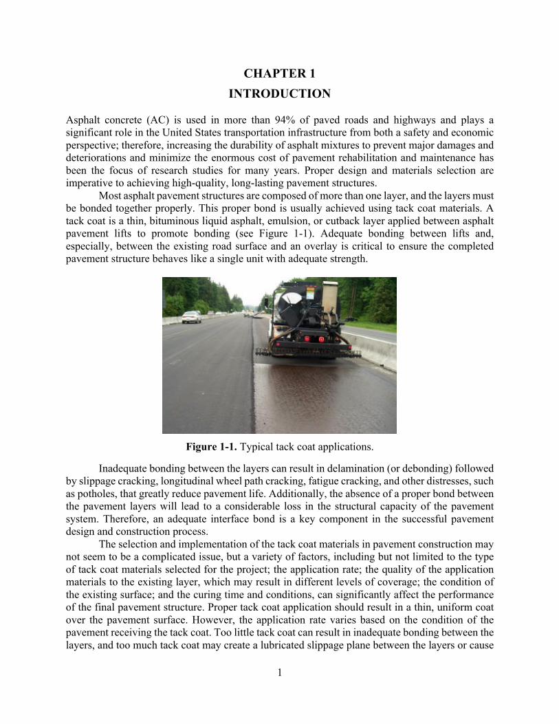
Most asphalt pavement structures are composed of more than one layer, and the layers must be bonded together properly. This proper bond is usually achieved using tack coat materials. A tack coat is a thin, bituminous liquid asphalt, emulsion, or cutback layer applied between asphalt pavement lifts to promote bonding (see Figure 1-1). Adequate bonding between lifts and, especially, between the existing road surface and an overlay is critical to ensure the completed pavement structure behaves like a single unit with adequate strength.
Figure 1-1. Typical tack coat applications.
Inadequate bonding between the layers can result in delamination (or debonding) followed by slippage cracking, longitudinal wheel path cracking, fatigue cracking, and other distresses, such as potholes, that greatly reduce pavement life. Additionally, the absence of a proper bond between the pavement layers will lead to a considerable loss in the structural capacity of the pavement system. Therefore, an adequate interface bond is a key component in the successful pavement design and construction process.
The selection and implementation of the tack coat materials in pavement construction may not seem to be a complicated issue, but a variety of factors, including but not limited to the type of tack coat materials selected for the project; the application rate; the quality of the application materials to the existing layer, which may result in different levels of coverage; the condition of the existing surface; and the curing time and conditions, can significantly affect the performance of the final pavement structure. Proper tack coat application should result in a thin, uniform coat over the pavement surface. However, the application rate varies based on the condition of the pavement receiving the tack coat. Too little tack coat can result in inadequate bonding between the layers, and too much tack coat may create a lubricated slippage plane between the layers or cause

2
the tack coat material to be drawn into the overlay, negatively affecting the mix properties and creating the potential for bleeding within the thin overlay. Table 1-1 shows the typically recommended tack coat material application rates for different pavement conditions (Ohio, 2011).
Table 1-1. Typical Application Rates of Tack Coat Materials (Ohio,2001)
Note: Residual: the application rate of just the asphalt binder content of the emulsion
Undiluted: the application rate of the undiluted emulsion Diluted 1:1 with water: the application rate of an emulsion diluted 1:1 with water
The most common type of asphalt material currently in use for tack coat applications is
asphalt emulsion. An asphalt emulsion is a combination of an asphalt binder (asphalt cement), water, and a very small amount of an emulsifying agent (normally less than 1%). Typical asphalt emulsions are 55–70% asphalt binder, depending on the grade of the emulsion. Most grades of the asphalt emulsion used for tack coat applications are 60–65% asphalt binder. When the water in the emulsion evaporates, the residual asphalt content in the emulsion remains on the pavement surface. Typically, an asphalt emulsion commonly used for a tack coat application is approximately two-thirds asphalt binder and one-third water. A number of different grades of emulsion are used, including both rapid- and slow-set-type materials. The most commonly used rapid-set emulsions are: RS-1, RS-1h, CRS-1, and CRS-1h. The most common grades of slow-set emulsions are: SS-1, SS-1h, CSS-1, and CSS-1h. Sometimes, the asphalt emulsion may be polymer-modified for high-traffic roadway paving projects.
Using an asphalt emulsion as a tack coat material is typical in most tack-coating practices; however, its application is case-sensitive based on many factors, such as the type and condition of the pavement surface, the type of terrain where the pavement is located, and the environmental conditions at the time of paving. For instance, if an asphalt emulsion is used for the tack coat and if the humidity or ambient temperature is very high, the emulsion setting and curing time must be extended. The same is true if the pavement surface is damp from rain. Reducing the residual amount of tack coat by 0.01 gal/yd2 or keeping the residual application rate on the lower side of the suggested range would also be prudent. A change in the type of tack, from a soft asphalt emulsion to a hard asphalt emulsion (SS-1 to SS-1h, for example) should also be considered.
In some cases, a change from an asphalt emulsion to an asphalt binder may be feasible. Asphalt binder can be used for tack material instead of asphalt emulsion. In this instance, the tack coat is 100% asphalt cement. The grade of the asphalt binder selected is typically the same as the binder incorporated into the asphalt concrete mix. In most cases, the asphalt binder tack coat material meets the requirements of a performance-graded (PG) binder (e.g., PG 64-22 or PG 58-28).

3
Asphalt emulsions, such as CSS-1h have been successfully and widely applied to the pavements in Nebraska; however, other alternatives need to be considered in cases where the use of an asphalt emulsion could raise issues and is not an optimal approach. In these cases, asphalt overlaying with different tack-coating methods than the conventional asphalt emulsion-based approach may be considered. Due to their numerous advantages and benefits, thin asphalt overlays are becoming increasingly adopted in Nebraska as a promising pavement preservation approach, and the thin overlay practice is expected to grow for future projects. The effect of tack coats (in particular, the bonding between the layers) is considered particularly significant when a thin lift is overlaid on an existing, old (and aged) pavement surface. In addition to the mechanical bonding effect, the economical/practical benefits of the thin asphalt overlay are expanded by incorporating a faster tack coat application than the typical asphalt emulsion-based approach, which requires a significant amount of time for emulsion breaking and curing before a new layer is placed on an existing layer. A better engineered tack-coating application method for the thin asphalt overlay practice that provides more immediate bonding and faster placement of the tack coat than the current emulsion-based method is needed. 1.1 Research Objectives Currently, CSS-1h (i.e., cationic asphalt emulsion with slow setting characteristics) is the most common type of tack coat emulsion used in Nebraska; it is employed in most of the state’s projects. According to the Nebraska Department of Roads (NDOR) specifications (Nebraska, 2007), all tack coat emulsion should be diluted by equal volume with water to reach the 30% rate of residual binder. Two different application rates are also recommended by the specifications, depending on the condition of the existing layer. However, the entire state of Nebraska experiences significant seasonal variations in temperature and precipitation as well as different humidity levels, which makes the emulsified asphalt curing time an important factor since it could significantly influence the duration of asphalt overlay’s construction, which affects traffic delays. Hence, the primary objective of this research was to evaluate different tack coating practices for asphalt overlays in Nebraska. Therefore, the behavior of several tack coat materials, including various types of emulsions and binders with multiple application rates, were evaluated in this study using laboratory testing methods on field core samples. 1.2 Organization of Report
This report includes six chapters. After this introduction, Chapter 2 provides the background and a review of studies conducted in the tack coat research area, including the different test methods developed to evaluate the interlayer properties of asphalt pavement. Chapter 3 presents the materials and testing facilities used in this study as well as the sample fabrication methods of the laboratory-prepared testing specimens. Chapter 4 illustrates the field test plan for tack coat implementation and a detailed process of the field core samples’ acquisition. Chapter 5 discusses the laboratory testing methods and the results used to evaluate the interlayer properties of the core samples taken from the field section. Finally, Chapter 6 summarizes the main findings and conclusions of this study.

4
CHAPTER 2 BACKGROUND
2.1 Benefits of Tack Coat Materials The adequate bonding of pavement layers is one of the key factors in long-lasting pavement structures. It prevents many types of distress in the pavement system. Tack coating is the most widely used method to produce a proper bond between new and existing asphalt layers. According to the ASTM D8 (2011), Standard Terminology Relating to Materials for Roads and Pavements, tack coating is defined as an application of bituminous material to an existing relatively non-absorptive surface to provide a thorough bond between old and new surfacing. Fully bonded pavement layers are not only crucial to prevent the initiation and development of pavement distress, but they may also enhance the structural capacity of the whole pavement system because bonded pavement reduces the extent of the deflection at the bottom of the layers by holding the layers together and making them work as a monolithic system rather than separate structural units. 2.2 Types of Tack Coat The most commonly used tack coat materials are emulsified asphalt (also known as asphalt emulsion) and asphalt binder; however, the application of binders as tack coats is less common than the application of emulsions. An emulsified asphalt is liquid asphalt cement emulsified with water and is approximately 60% asphalt and 40% water and an emulsifying agent or emulsifier. Emulsified asphalts are classified based on the type of emulsifying agent used to produce them, which significantly affects the properties of the emulsions. For example, cationic emulsions with positively charged particles are believed to be more compatible with gravel and siliceous aggregates, while anionic emulsions with negatively charged particles generally have better adhesion on positively charged aggregates, such as limestone.
Another way to classify emulsified asphalts is based on their setting time (curing time). Emulsions are generally divided into three types: rapid setting (RS), medium setting (MS) and slow setting (SS), and the curing times increase from rapid-setting to slow-setting materials. As a result, tack coat emulsions should be selected based on the types of aggregate used in the asphalt mixture production, climate conditions, surface conditions, etc.
The results from a worldwide survey conducted by the International Bitumen Emulsion Federation (2001) show that the most widely used tack coat material is cationic emulsions. In 1988, Paul and Scherocman found that slow-setting emulsions are used by almost all the state departments of transportation (DOTs). One of the most comprehensive worldwide survey studies in the area of tack coat practices was conducted by the National Cooperative Highway Research Program (NCHRP) Project 9-40 (Mohammad et al., 2012) and found that asphalt emulsions are permitted by all the responding agencies while asphalt cement is only permitted by 27% of the respondents. Moreover, the most frequently used emulsions were SS-1 (41%), CSS-1h (41%), SS-1h (39%), and CSS-1 (37%). PG 64-22 was the most commonly used asphalt binder tack coat. 2.3 Application Rate The amount of tack coat applied between the asphalt layers is one of the most significant factors in the bond strength of the layer interfaces. Pavement surface condition has been a widely-used criterion for the selection of the application rate in many standard manuals and specifications.

5
Generally, overlays in pavements with old asphalt mixtures or milled surfaces require higher application rates than surfaces with new asphalt mixtures. In many cases, the dilution of emulsions with water prior to spraying is allowed or recommended to enhance the coating capability of the emulsion. However, the residual application rate of the asphalt emulsion determines the interlayer properties. The residual asphalt content is defined as the amount of remaining asphalt after the emulsion has broken and set (all water has evaporated). Therefore, the residual application rate, not the application rate of the original or diluted emulsified asphalt, should be considered the target parameter to determine the proper application rate.
The dilution rate may also considerably affect the breaking and setting time. Breaking time is usually referred to as the time period in which the water separates from the asphalt cement, while the emulsion is “set” when all the water, including the original water and the dilution water, has evaporated. The breaking and/or setting time may vary from a few minutes to several hours, depending on the type of emulsion, weather conditions (e.g., temperature, wind, moisture level), and asphalt surface condition (e.g., types of aggregate or mixture). The distinction of the broken and unbroken emulsions is typically based on color. The original color of the asphalt emulsion is brown due to the existence of water. As time passes, the material loses the water and turns from brown to black. Although there is no general agreement on whether or not placement of the next asphalt layer must be delayed to allow the emulsion to set or how long this lapse of time should be, Paul and Scherocman (1998) found that many state DOTs specified a minimum time between the tack coat application and the placement of the asphalt mixture to provide adequate curing time so the emulsion would to break and set. As a result, the curing time delay may become an issue in cases in which traffic is obstructed to accommodate the construction process.
Several studies evaluated the optimum application rate of the tack coat materials to achieve the maximum interface bond strength. According to a survey conducted by Paul and Scherocman (1998), the residual application rates of the asphalt emulsions were between 0.01 and 0.06 gal/yd2, depending on the surface condition. In addition, Asphalt Institute (AI) specifications (1989) state that the residual application rate varied, ranging from 0.02 to 0.05 gal/yd2. The NCHRP Project 9-40 (Mohammad et al., 2012) recommends the residual application rates for different pavement surface types (see Table 2-1).
Table 2-1. Recommended Tack Coat Residual Application Rate
Surface Type Residual Application Rate (gal/yd2)
New asphalt mixture 0.035
Old asphalt mixture 0.055
Milled asphalt mixture 0.055
Portland cement concrete 0.045
2.4 Tack Coat Related Distresses Poor interface bonds between asphalt layers could lead to various types of damage in the pavement structure system. Two common tack coat-related distresses are delamination and slippage cracking. Delamination occurs when the top layer is separated from the bottom layer due to the lack of a proper bond between the layers. Figure 2-1 shows typical delamination damage.

6
Figure 2-1. Delamination distress.
Slippage cracking (see Figure 2-2) is another common type of tack coat-related distress. This distress is caused by sliding the surface layer over the layer beneath it when sufficient shear resistance between layers does not exist. This type of cracking occurs in areas where vehicles typically accelerate, decelerate, or turn. It may also occur as a result of the non-uniform application of tack coat or in the wheel path if the tack coat material is picked up by the tires of haul trucks during the construction period. Slippage cracking may also occur if the existing layer is dusty or dirty. Poor bonding may also activate and accelerate other types of distress, such as bottom-up fatigue cracking. Park (2013) and Tayebali et al. (2004) concluded that pavement failure often occurs at the layer interface due to a poor bond between the adjacent asphalt concrete layers.
Figure 2-2. Slippage cracking.
2.5 Test Methods to Evaluate Bond Strength Agencies and research groups have developed several laboratory and field test methods during the last decade to determine the bond strength of the interlayers. However, it has been challenging in many cases to capture the realistic behavior of the tack coat interlayers due to the effects of the actual traffic load placed on the pavement. Bond failure at the interface is generally classified into three modes (see Figure 2-3): shear failure (Mode A), tensile failure (Mode B), and mixed shear-tensile failure (Mode C) (Sutanto, 2009).

7
Figure 2-2. Interlayer bond failure modes (Sutanto, 2009).
The test methods developed to evaluate the bond strength of an interface are categorized into two general groups: monotonic loading tests and cyclic loading tests. However, the former is more widely implemented than the latter. Monotonic tests can then be subdivided into three groups: shear, torsional, and tensile testing. Gierhart and Dietz (2015) summarized the pros and cons of each type of test as follows:
v Shear Testing: • Laboratory test; • Quick; • Repeatable; • Most widely used; • Uses common laboratory equipment; • Able to clearly rank materials.
v Torsional Testing: • Laboratory or field test; • Quick; • Poor repeatability (manual run).
v Tensile Testing: • Laboratory or field test; • Quick; • Repeatable; • Able to clearly rank materials.
NCAT Shear Test NCAT (2005) has developed a direct shear tester to evaluate the shear strength of tack coat materials. The updated version of the NCAT shear fixture (see Figure 2-4) is capable of applying horizontal load to the samples. The test is performed on 6-in-diameter (150 mm) samples. The thickness of the layers on each side of interface should be no less than 2 in and no larger than 6 in. The gap between the specimen holder should be 0.25 in. The test is performed in displacement controlled mode with the rate of 2 in (50.8 mm) per minute. The Marshall stability test apparatus could be adopted for this test.

8
Figure 2-3. NCAT bond strength fixture.
Layer-Parallel Direct Shear (LPDS) The Swiss Federal Laboratories for Material Testing and Research developed a shear testing device called LPDS that is a modified version of device developed in Germany by Leutner (1979). The device is used in Swiss Standard SN 671 961. It uses 6-in-diameter samples to apply direct shear load at a displacement rate of 2 in (50.8 mm) per minute at a temperature of 20°C. UTEP Pull-Off Test The Texas DOT UTEP Pull-Off Test was developed at the University of Texas at El Paso (Deysarkar, 2004). The device measures the tensile strength of the tack coat before the placement of an overlay in the field. The device (see Figure 2-5) consists of a plate that is firmly set on the tack-coated pavement. A 40-lb load is then placed on top of the equipment for 10 min to set the contact plate. After removing the load, torque is applied using a wrench until the contact plate is detached from the pavement surface. Finally, the force required to remove the plate from the tack coat materials is converted to the strength.
Figure 2-4. UTEP pull-off testing device (Deysarkar, 2004).

9
FDOT Shear Tester A simple direct shear test was designed as a part of a study done by the Florida DOT (2002). The device holds 6-in-diameter specimens since it was believed that 6-in samples would result in less variability than 4-in samples. The fixture was also manufactured so the gap between the shearing plates is adjustable. The test is run using a loading rate of 2 in per minute at a temperature of 77°F. Figure 2-6 displays the Florida DOT shear fixture.
Figure 2-5. Florida DOT shearing apparatus.
Torque Bond Test
The Torque Bond test was initially developed in Sweden for the in-situ testing of asphalt interfaces. This method has also been adopted in UK as a part of the approval process for thin surfacing pavements. In this test, torque is applied to the top of the sample using a torque wrench connected to a steel plate that is glued to the sample’s surface (see Figure 2-7). The force needed for failure can then be used to calculate the interlayer bond strength. The test method was originally designed to be performed in the field, but the test was later adjusted so it could be conducted in a more controlled environment (Choi, 2005).
Figure 2-6. Torque bond test (Image from Tashman, 2006).

10
Louisiana Interlayer Shear Strength Tester (LISST) Another type of direct shear test, referred to as the Louisiana Interlayer Shear Strength Tester (LISST) (see Figure 2-8), was developed during the NCHRP Project 9-40 (Mohammad et al., 2012). The device works similar to the direct shear methods previously mentioned and consists of two main parts: a shearing frame that is allowed to move and a fixed reaction frame. The fixture holds samples with 100 mm or 150 mm diameters and accommodates sensors to measure the vertical and horizontal displacements. A standard testing procedure has been released by AASHTO. The standard specifications are based on the results from the use of the LISST device during the NCHRP Project 9-40. AASHTO TP 114 (2016) “Provisional Standard Method of Test for Determining the Interlayer Shear Strength (ISS) of Asphalt Pavement Layers” recommends using a 5.9 in (150-mm) specimen diameter and height above or below the interface, but less than 2 in. The displacement rate is 0.1 in per minute, and the gap between the loading and reaction frames is 1/2 in. The standard does not necessitate the use of confining pressure. However, if required, a normal pressure actuator is able to apply up to 30 psi of pressure on the sample.
Figure 2-7. Louisiana interlayer shear strength tester (LISST).
Shear Fatigue Test
Several studies have investigated the behavior of the interlayers under cyclic loading in an attempt to determine the interlayer performance under repetitive traffic loading. Romanoschi et al. (2001) developed a testing configuration (see Figure 2-9) to determine the shear fatigue behavior of the interface. They applied normal force to the samples by placing the specimen with the longitudinal axis at an angle with the vertical so that the shear stress at the interface was half the normal stress. A haversine vertical load with a frequency of 5 Hz was applied, and the number of cycles that produced an increase of 1.0 mm in permanent shear deformation was used as the failure criterion.

11
Figure 2-8. Shear fatigue test (Romanoschi, 2001).
Virginia Shear Fatigue Test
Donovan et al. (2000) used the fatigue shear test to optimize the application rate of the tack coat for geo-composite membranes in bridge decks. The test was performed on an interlayer that was sandwiched between a Portland cement concrete slab and an asphaltic layer. The test was also conducted in a displacement controlled mode using a cyclic shear load of 0.10-seconds haversine wave with a deflection of 0.4 mm followed by a rest period of 0.9 seconds. Failure was identified when the slope of the applied stress versus the logarithm of the number of cycles reached zero. Figure 2-10 illustrates the Virginia shear fatigue test fixture.
Figure 2-9. Virginia shear fatigue test fixture (Donovan et al. 2000).

12
CHAPTER 3 MATERIALS, SAMPLE FABRICATION AND TESTING FACILITIES
3.1 Tack Coat Materials Selection According to the Nebraska Department of Roads (NDOR) specifications “Standard Specification for Highway Construction,” both anionic and cationic emulsified asphalt can be used as tack coat materials, but there is no guideline or requirement regarding the application of asphalt cement as a tack coat. However, anionic and cationic emulsified asphalt must meet the AASHTO M 140 and AASHTO M 208 requirements, respectively. Cationic emulsions are common tack coats used in the state of Nebraska, and CSS-1h is the most widely used tack coat.
The state of Nebraska experiences significant seasonal variations in temperature and precipitation as well as different humidity levels, and the breaking and setting time of the emulsions are considerably dependent on environmental conditions. As a result, one of the main objectives of this research project was to compare the performance of different types of tack coat materials. This study also evaluated the materials’ breaking time and its effect on construction time span, which affects traffic delays due to road work activities.
This study evaluated the effectiveness of the application of five types of materials as tack coats for asphalt overlays. The tack coats for this project included: CSS-1h, CRS-2P, CFS-1, PG 64-22 and PG 64-22 plus a wax additive as a trackless tack coat. Comparing to CSS-1h (slow-setting type), CRS-2P which is a rapid-setting emulsified asphalt and CFS-1 which is a modified CSS-1 to provide a faster set were selected to evaluate the difference in the breaking time in the field and to compare their bond behavior as tack coats. 3.2 Application Rates According to NDOR specifications, emulsified asphalt should be diluted in the distributor with sufficient water to reduce the asphalt content in the mixture to approximately 30% of the total volume. Since emulsions are usually supplied at 60% residual asphalt and 40% water, the specifications recommend the addition of water to obtain an emulsion with 30% residual asphalt content. The application rates designated in the specification are 0.10 to 0.20 gal/yd2 (i.e., 0.45 to 0.90 L/m2) when applied to existing or milled surfaces and 0.05 to 0.10 gal/yd2 (i.e., 0.23 to 0.45 L/m2) when applied to freshly laid asphaltic concrete. These application rates recommend a 50% dilution (the addition of an equal volume of water to the original emulsion) to acquire a proper bond between the new asphalt layer and the existing surface.
Throughout this research, two main application rates were used in the emulsified tack coats: the typical application rate (0.08 gal/yd2) used in most of the state projects and recommended by the specifications and double the standard application rate (0.16 gal/yd2) to identify the effect of using higher rates than those used in current typical tack coat practices. For asphalt binder tack coats, the standard application rate was considered to be achieved when visual observation revealed full coverage of the pavement surface. The standard and double application rates were also used for asphalt binder tack coats. 3.3 Testing Facilities
A direct shear testing (DST) fixture manufactured by the PINE company was used to assess the bond behavior of the interlayers in shear failure mode. The fixture accommodates 2-in to 6-in-

13
diameter specimens using a reducer kit. The fixture consists of a moving frame and a reaction frame, and the gap between the frames is adjustable from zero to ¾-in. The normal force kit is also capable of applying up to 15 psi of normal pressure to the samples. In the normal force assembly, the deformation of a standard spring is recorded using a digital gauge and is then converted to force. Figure 3-1 shows the DST fixture used in this study.
Figure 3-1. Direct shear fixture.
One factor that could affect the DST results on the field cored samples is the gap width
between the moving and reaction frames. It is necessary to have enough gap to account for the field cored samples having a layer interface plane that is not exactly perpendicular to the side of the cylindrical core. If the gap does not exist in the frames and the interface plane is not completely perpendicular to the side of sample, a failure surface that is partially out of the interface shear plane would occur, which would lead to capturing forces that do not represent the interlayer shear bond strength alone. However, a large gap width must be avoided since it would result in flexural stress on the sample during shearing, creating a mixed shear-bending failure mode. In this study, a gap width of 1/2 in was adopted as recommended by AASHTO TP 114.
All mechanical tests were conducted using the 25-kN capacity Universal Testing Machine (UTM-25kN) shown in Figure 3-2. This equipment is composed of an environmental chamber, a central data acquisition system (CDAS), and a hydraulic pressure system. It can produce a maximum of 25 kN static and 20 kN of cyclic loading (at various frequencies). The environmental chamber can precisely control temperatures ranging from -15 ~ 60°C. However, to ensure an accurate temperature reading and guarantee the target testing temperature, a dummy sample with an internal thermometer was placed inside the chamber along with the specimens.

14
Figure 3-2. UTM-25kN testing equipment.
3.4 Laboratory-Prepared Samples
In the first stage of this study, a series of direct shear tests on samples prepared in the laboratory was conducted to examine the sensitivity and effectiveness of the testing method and to finally determine the testing conditions used in this project. Several testing variables/factors may influence the shear bond behavior of the interlayers. The experimental factors used in the first stage are summarized in Table 3-1.
Table 3-1. Laboratory-Prepared Experimental Plan
Experimental Parameters Condition
Sample Size (in) 4, 6
Temperature Low, Intermediate
Normal Pressure (psi) 0, 10
Tack Coat CSS-1, CFS-1
Application Rate (gal/yd2) (50% dilution)
0-0.2
Mixture Type SPR, SLX

15
The laboratory specimens consisted of two layers with an interface between them. First, the plant produced loose asphalt mixtures were reheated in an oven for two hours to the required compaction temperature (i.e., 300°F). The first layer was then compacted using the Superpave gyratory compactor (SGC) to a height of 2 in with a target air void of 6.0 ± 1.0%. After the first layer was removed from the mold and cooled, the sample was placed on a scale and the required amount of tack coat at the specified target application rate was applied to the surface of the sample (see Figure 3-3). The sample was kept at room temperature until the tack coat was completely broken. The emulsified tack coat is considered broken when its color turns from brown to black (see Figure 3-4). Two types of curing methods were used to evaluate the effect of wind conditions on the breaking time. One set of samples was cured in normal room conditions, while another set was cured using a fan to simulate windy weather conditions. The first compacted layer containing the tack coat was then placed in a heated SGC mold and a loose mixture was placed on top of tack-coated bottom layer. The second layer was finally compacted to a height of 2 in (50 mm) with the same air void of 6.0 ± 1.0% so that the final height of completed sample was 4 in. Figure 3-5 shows the final sample after compaction with the tack coat interlayer between two layers.
Figure 3-3. Application of tack coat emulsion.
(a) (b)
Figure 3-4. Tack coat emulsion: (a) before breaking, (b) after breaking.
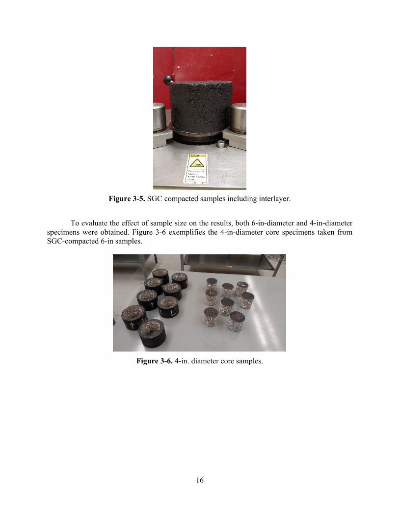
16
Figure 3-5. SGC compacted samples including interlayer.
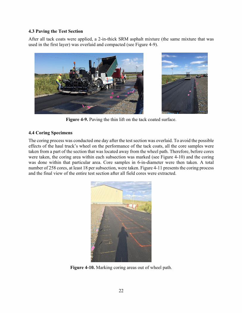
To evaluate the effect of sample size on the results, both 6-in-diameter and 4-in-diameter
specimens were obtained. Figure 3-6 exemplifies the 4-in-diameter core specimens taken from SGC-compacted 6-in samples.
Figure 3-6. 4-in. diameter core samples.

17
CHAPTER 4 FIELD TEST PLAN
The laboratory-prepared samples and field core-extracted samples will not necessarily lead to similar tack coat interlayer behavior results due to many factors, including different mixing and compaction methods. In fact, the interlayer shear strength results obtained from NCHRP Project 9-40 revealed that laboratory-prepared samples containing a tack coat interface could provide significantly different, and even misleading results than field cored samples using the same materials and the same application rates. Therefore, in this study, cores taken from a field test section were employed to evaluate the performance of different tack coat materials in a more realistic manner. The field implementation of different types of tack coats was essential to identify the period of time needed for the breaking and setting of the emulsions in actual field construction conditions. This chapter discusses the field work performed to acquire the core specimens tested. 4.1 Test Section Configuration
The construction of the pavement test section and tack coating process was conducted in the NDOR maintenance yard near Oconto, NE (41°08'01.7"N, 99°45'29.7"W). The test section was constructed using two asphaltic layers. The first layer was placed and compacted to the target thickness of 2 in a few days before the tack coating stage. The dimensions of the test section were 23 ft in width and approximately 90 ft in length. The asphalt mixture used in the pavement’s construction was the Nebraska SRM mixture, which is a bituminous base mixture typically used to replace a hydrated lime slurry-stabilized base and/or cold foam reclamation layer. The whole section was then subdivided using paint marking into 14 subsections that were 4 ft wide and 23 ft in length. Figure 4-1 shows the configuration of the test section and its subsections. There was also a 2-ft gap between each subsection.
Figure 4-1. Configuration of field test section.
4.2 Tack Coat Distribution
Five types of tack coat materials, which can be divided into two general groups of emulsified asphalts and asphalt binders, were used in this project. The tack coating process of the test section was conducted on September 8, 2016. The air temperature varied from 61°F to 73°F during

18
construction, and the average wind speed was around 9 mph. The method used to distribute the materials to the field section and their application rates are discussed in the following subsections. 4.2.1 Emulsion Tack Coats
Three types of emulsions, CSS-1h, CRS-2P and CFS-1, were used. For CSS-1h, two different dilution rates were applied: the 50% dilution rate recommended by the standard specifications and a 30% dilution rate (i.e., 70% original emulsion plus 30% additional water). CRS-2P and CFS-1 were applied without dilution. For each type of emulsion and each dilution rate, two application rates were applied: the typical application rate specified in the standards (i.e., standard shooting rate) and double the standard application rate (i.e., double shooting rate). Thus, 8 of the 14 subsections were tack coated using emulsion materials. Since the dimensions of subsections did not allow the use of truck distributers during the emulsion application to the pavement surface, the emulsion tack coats were applied to the subsections manually. Moreover, to check the application rates after the tack coating process, a pad was taped to the pavement along the entire test section (see Figure 4-2). The weight of the tack coat material applied to the pad was then calculated by simply subtracting the weight of the pad plus the tape from the weight of the pad, tape, and tack coat material. The following steps were taken during the tack coating process:
• Using the dimensions of each subsection as well as the specific gravity of the emulsions provided by supplier, the weight of the emulsified asphalt required to obtain the target application rate was calculated;
• Using buckets and a scale, the amount of the emulsions measured in the previous step was acquired. For the subsections that required dilution, water was added to the emulsions. The water and emulsions were mixed thoroughly with the original mixture using a drill (see Figure 4-3);
• The emulsified asphalt was then evenly spread onto the subsection and distributed using brooms and squeegees to cover all the parts of the subsection. Figure 4-4 illustrates the distribution of the emulsion tack coats;
• Once the subsection was fully covered with the tack coat, the breaking time was recorded. The breaking time was considered to be the point at which the emulsions turns from brown to black. Figure 4-5 displays the subsections before and after the emulsion breaking.
Figure 4-2. A pad placed on surface of field pavement section.

19
Figure 4-3. Dilution of emulsified asphalt.
Figure 4-4. Distributing tack coat emulsion on the section.

20
Figure 4-5. Breaking of tack coat emulsions.
4.2.2 Asphalt Binder Tack Coats Five sections were tack coated using asphalt binders. Trailer-mounted asphalt spray equipment (Figure 4-6a) was used to spray the binder tack coats onto the pavement. Subsections #9 and #10 were covered by PG 64-22, while subsections #11, #12, and #14 were covered by a wax modified PG 64-22 at 330°F. The binder tack coat distribution process included the following steps:
• The rate at which the asphalt distributer sprayed the binder was identified. The binder was sprayed into a bucket with a known weight for a specified period of time (e.g., 1 minute) (see Figure 4-6b). Using the weight of the binder in the bucket, the rate was then calculated in terms of kg/min by dividing the weight of the sprayed binder by the time;
• To obtain the standard application rate, the specified subsections were tack coated using asphalt distributing equipment until full coverage of the subsection was identified using visual judgment. The time taken to cover the subsections with binder tack coats was recorded. The final application rate was then determined by converting the weight of the applied binder to volume. To acquire the double application rate, the binder was applied for double the amount of time required from the standard application rate.
(a) (b)
Figure 4-6. Asphalt spray equipment used for binder tack coats.

21
Figures 4-7a and 4-7b show the binder tack coat distribution and a final view, respectively. One subsection (#14) was tack coated with a wax modified PG 64-22 using the same method of distribution that was used for the emulsion tack coats. Subsection #13 was the control section, where no tack coat was applied to it. The schematic view of entire test section (all 14 subsections) is illustrated in Figure 4-8.
(a) (b)
Figure 4-7. Distribution of binder tack coats.
Figure 4-8. Schematic view of test section (14 subsections).
22
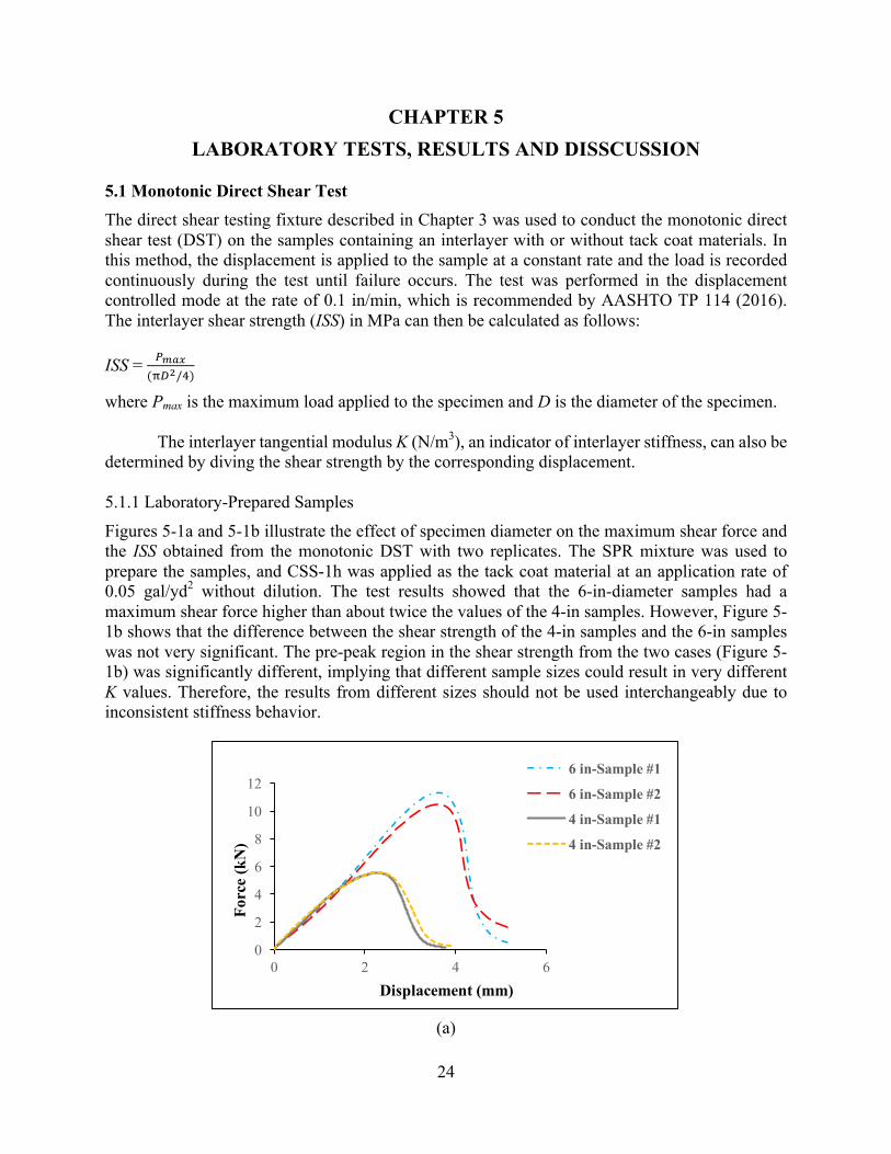
4.3 Paving the Test Section After all tack coats were applied, a 2-in-thick SRM asphalt mixture (the same mixture that was used in the first layer) was overlaid and compacted (see Figure 4-9).
Figure 4-9. Paving the thin lift on the tack coated surface.
4.4 Coring Specimens The coring process was conducted one day after the test section was overlaid. To avoid the possible effects of the haul truck’s wheel on the performance of the tack coats, all the core samples were taken from a part of the section that was located away from the wheel path. Therefore, before cores were taken, the coring area within each subsection was marked (see Figure 4-10) and the coring was done within that particular area. Core samples in 6-in-diameter were then taken. A total number of 258 cores, at least 18 per subsection, were taken. Figure 4-11 presents the coring process and the final view of the entire test section after all field cores were extracted.
Figure 4-10. Marking coring areas out of wheel path.

23
Figure 4-11. Coring 6-in. diameter samples.
All the cores were then collected, labeled with a paint pen, and transferred to the PI’s
Materials Laboratory. Before testing each core, the core samples with a height above the interface target of 2 in were cut using a wet masonry saw machine to a height of less than 2 in (see Figure 4-12). The interface in the cores was also marked to ensure an accurate testing process.
Figure 4-12. Cutting samples to prepare laboratory testing specimens.
24
CHAPTER 5 LABORATORY TESTS, RESULTS AND DISSCUSSION
5.1 Monotonic Direct Shear Test The direct shear testing fixture described in Chapter 3 was used to conduct the monotonic direct shear test (DST) on the samples containing an interlayer with or without tack coat materials. In this method, the displacement is applied to the sample at a constant rate and the load is recorded continuously during the test until failure occurs. The test was performed in the displacement controlled mode at the rate of 0.1 in/min, which is recommended by AASHTO TP 114 (2016). The interlayer shear strength (ISS) in MPa can then be calculated as follows: ISS = !"#$
(&'(/*)
where Pmax is the maximum load applied to the specimen and D is the diameter of the specimen. The interlayer tangential modulus K (N/m3), an indicator of interlayer stiffness, can also be
determined by diving the shear strength by the corresponding displacement. 5.1.1 Laboratory-Prepared Samples
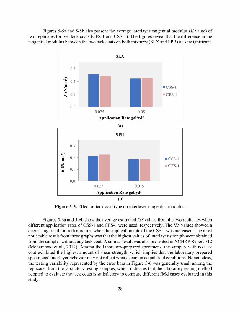
Figures 5-1a and 5-1b illustrate the effect of specimen diameter on the maximum shear force and the ISS obtained from the monotonic DST with two replicates. The SPR mixture was used to prepare the samples, and CSS-1h was applied as the tack coat material at an application rate of 0.05 gal/yd2 without dilution. The test results showed that the 6-in-diameter samples had a maximum shear force higher than about twice the values of the 4-in samples. However, Figure 5-1b shows that the difference between the shear strength of the 4-in samples and the 6-in samples was not very significant. The pre-peak region in the shear strength from the two cases (Figure 5-1b) was significantly different, implying that different sample sizes could result in very different K values. Therefore, the results from different sizes should not be used interchangeably due to inconsistent stiffness behavior.
(a)
0
2
4
6
8
10
12
0 2 4 6
Forc
e (k
N)
Displacement (mm)
6 in-Sample #1
6 in-Sample #2
4 in-Sample #1
4 in-Sample #2

25
(b)
Figure 5-1. The effect of sample size on interlayer properties.
The force versus the displacement results at two different temperatures are shown in Figure
5-2. Two replicates were tested at 5°C to evaluate low temperature behavior, while three replicates were tested at 25°C to evaluate intermediate temperature behavior. The SPR mixture and the CSS-1h at a rate of 0.05 gal/yd2 without dilution were used to produce 4-in testing specimens. Prior to testing, the specimens were placed inside the UTM environmental chamber and allowed a minimum of four hours to reach temperature equilibrium. The test results shown in the figure clearly demonstrate that the temperature noticeably affected the maximum shear force. Another main difference observed at the two different testing temperatures was the post-peak behavior of the tack coat interlayer. A sudden drop in force was observed at 5°C, while the force decreased more gradually before complete failure at the intermediate temperature condition.
Figure 5-2. Effect of temperature on interlayer maximum shear force.
00.10.20.30.40.50.60.70.8
0 2 4 6
ISS
(MPa
)
Displacement (mm)
6 in-Sample #1
6 in-Sample #2
4 in-Sample #1
4 in-Sample #2
0
5
10
15
20
25
0 1 2 3 4 5 6
Forc
e (k
N)
Displacement (mm)
25 C-Sample #1
25 C-Sample #2
25 C-Sample #3
5 C-Sample #1
5 C-Sample #2

26
To evaluate the effect of normal pressure on the interlayer strength, monotonic direct shear tests were conducted using 4-in specimens with and without normal pressure. The test results are presented in Figure 5-3. The mixture type and CSS-1h application rate were SPR and 0.05 gal/yd2, respectively. For the case with normal pressure, 10 psi was applied to the specimens perpendicular to the shear force. As illustrated in the figure, the presence of normal pressure generally induced slightly increased maximum shear force compared to the case without a normal force applied.
Figure 5-3. Effect of normal pressure on shear behavior.
Several studies show that the existence of normal force in a direct shear test increases the
interlayer shear strength. However, a general agreement on the necessity of including normal pressure during the shear test has not been reached. The level of pressure that needs to be applied is also debatable since differences in the level of normal pressure could provide completely different results. To simulate the realistic condition of the interlayer under actual wheel load, a 0.5 ratio between the vertical and horizontal forces has been proposed, resulting in a shear stress at the interface that is half the normal rate (Salam et al. 1973, Shahin et al. 1987, Romanoschi et al. 2001), which could result in a very high level of normal stress (more than 70 psi). However, using high levels of normal pressure can be problematic because the pressure may represent the shear strength caused primarily by perpendicular confinement, not the bonding from the tack coat materials. Therefore, although the shear strength obtained without the application of normal force may not be completely appropriate for design and analysis purposes, it would still be useful to check the quality of tack coat applications. Since the main purpose of this research is to compare different tack coat materials and their applications, direct shear testing without a normal force was thus adopted.
Table 5-1 presents the test parameters used to evaluate the effect of different factors on the interlayer properties of the laboratory-prepared samples. The application rates shown in the table are the rates of the original emulsified tack coats without dilution.
0
1
2
3
4
5
6
7
0 1 2 3 4 5 6
Forc
e (k
N)
Displacement (mm)
Sample #1
Sample #2
Sample #3
NP-Sample #1
NP-Sample #2

27
Table 5-1. Testing Parameters
Mix Type Emulsion
Application Rate (gal/yd2)
0 0.025 0.05 0.75 0.1
SPR CSS-1 ü ü ü ü
CFS-1 ü ü
SLX CSS-1 ü ü ü
CFS-1 ü ü ü
The test results (i.e., interlayer shear strength, ISS) obtained from the different emulsified
tack coats are presented in Figures 5-4a and 5-4b. The average results reveal that in the CSS-1 and CFS-1 samples with lower application rates, the ISS values were higher for both types of mixtures (SPR and SLX). Conversely, in the samples with higher application rates, the CFS-1 sample had a higher ISS value than the CSS-1 samples.
(a)
(b)
Figure 5-4. Effect of tack coat type on interlayer shear strength.
0.0
0.2
0.4
0.6
0.8
1.0
0.025 0.05
ISS
(MPa
)
Application Rate gal/yd2
SLX
CSS-1
CFS-1
0.0
0.2
0.4
0.6
0.8
1.0
0.025 0.075
ISS
(MPa
)
Application Rate gal/yd2
SPR
CSS-1CFS-1
28
Figures 5-5a and 5-5b also present the average interlayer tangential modulus (K value) of two replicates for two tack coats (CFS-1 and CSS-1). The figures reveal that the difference in the tangential modulus between the two tack coats on both mixtures (SLX and SPR) was insignificant.
(a)
(b)
Figure 5-5. Effect of tack coat type on interlayer tangential modulus. Figures 5-6a and 5-6b show the average estimated ISS values from the two replicates when
different application rates of CSS-1 and CFS-1 were used, respectively. The ISS values showed a decreasing trend for both mixtures when the application rate of the CSS-1 was increased. The most noticeable result from these graphs was that the highest values of interlayer strength were obtained from the samples without any tack coat. A similar result was also presented in NCHRP Report 712 (Mohammad et al., 2012). Among the laboratory-prepared specimens, the samples with no tack coat exhibited the highest amount of shear strength, which implies that the laboratory-prepared specimens’ interlayer behavior may not reflect what occurs in actual field conditions. Nonetheless, the testing variability represented by the error bars in Figure 5-6 was generally small among the replicates from the laboratory testing samples, which indicates that the laboratory testing method adopted to evaluate the tack coats is satisfactory to compare different field cases evaluated in this study.
0.0
0.1
0.2
0.3
0.025 0.05
K(N
/mm
3 )
Application Rate gal/yd2
SLX
CSS-1
CFS-1
0.0
0.1
0.2
0.3
0.025 0.075
K(N
/mm
3 )
Application Rate gal/yd2
SPR
CSS-1CFS-1

29
(a)
(b)
Figure 5-6. Effect of application rate on interlayer shear strength. Regarding breaking time of tack coats, no significant difference in the breaking time was
found between the two tack coats, CSS-1 and CFS-1. As shown in Figure 5-7, for samples cured in normal conditions (without the presence of wind), increasing the application rates generally required more time to break. However, the breaking time for samples cured using a fan (simulating windy weather condition) dropped dramatically. In the presence of wind, all samples reached their breaking condition within approximately five minutes.
0.25
0.50
0.75
1.00
1.25
0 0.05 0.1 0.15
ISS
(MPa
)
Application Rate (gal/yd2)
CSS-1SPR
SLX
0.25
0.50
0.75
1.00
1.25
0 0.025 0.05 0.075 0.1
ISS
(MPa
)
Application Rate (gal/yd2)
CFS-1
SPR
SLX

30
Figure 5-7. Emulsion breaking time for SPR mixture.
5.1.2 Field Core Samples
The initial plan for the field evaluation was to take field cores from a pavement construction site where an overlay is placed on the existing milled surface. However, there were concerns that the test results on a milled surface may bring misled results toward the evaluation of the effect of the tack coat on shear bonding behavior since the rough surface between the milled layer and the new overlay may affect the interlayer shear behavior. Therefore, the results may not provide a clear comparison between different tack coat materials and applications. To further investigate this issue, a few samples were taken from a pavement section that consisted of three layers; two new layers, each of which was 2 in thick, and an old milled layer with a thickness of 4.5 in. The direct shear test was then performed on the two different testing samples: samples with two new layers and samples with a new layer and an old milled layer. Based on the average results shown in Figure 5-8, the effect of milling on the ISS values was significant. Figure 5-9 also illustrates the interface failure on the samples after the test. A very rough failure surface was identified on the samples with the milled interlayer as opposed to the very smooth failure surface seen on the samples with the non-milled surface. As a result, it was concluded that the non-milled interlayer could be more suitable to evaluate the differences in the performance of the tack coat materials subjected to shear debonding, as targeted in this study. A corresponding field test plan was developed, and the results are discussed in this chapter.
Figure 5-8. Effect of milling on interlayer shear strength.
0
20
40
60
80
0.025 0.05 0.075 0.1
Tim
e (m
in)
Application Rate
SPR
CSS-1CSS-1. FanCFS-1CFS-1. Fan
0
50
100
150
200
250
300
Milled Non-Milled
ISS
(kPa
)

31
(a) (b) Figure 5-9. Failure surface after DST: (a) sample with milled, (b) sample with non-milled.
Table 5-2 presents the target and final (i.e., residual) application rates obtained from the
field section. The breaking time of the emulsion tack coats in the field is presented in Figure 5-10. An increase in the application rate caused the breaking time to increase, and in some cases, a significant difference in breaking time was observed between the different emulsion types. The CSS-1h case with a 30% dilution rate and a double application rate (i.e., CSS-1h (70/30) × 2) showed the longest breaking time (i.e., 35 min), while the CRS-2P case with a standard application rate showed the shortest breaking time (i.e., 5 min). In general, the subsections coated by CRS-2P required much shorter breaking times than the other subsections.
Table 5-2. Target Application Rates and Residual Application Rates on Field Sections
Section No
Tack Coat
Target Application Rate (gal/yd2)
Residual Application Rate (gal/yd2)
1 CSS-1h (50/50) 0.08 0.04 2 CSS-1h (50/50) × 2 0.16 0.08 3 CSS-1h (70/30) 0.08 0.056 4 CSS-1h (70/30) × 2 0.16 0.112 5 CRS-2P 0.08 0.1 6 CRS-2P × 2 0.16 0.16 7 CFS-1 0.08 0.08 8 CFS-1 × 2 0.16 0.16 9 PG 64-22 Standard Coverage 0.26 10 PG 64-22 × 2 Double 0.53 11 Wax modified PG Standard Coverage 0.26 12 Wax modified PG × 2 Double 0.52 13 No Tack - - 14 Wax modified PG
(Hand Dis) × 2 Double 0.69

32
Figure 5-10. Breaking time of emulsified tack coats.
To evaluate and compare the performance of the different tack coat materials and their
application rates under various conditions, a monotonic direct shear test of the field cored samples was performed at three different temperatures: low (5°C), intermediate (25°C), and high (60°C). At least three replicates were tested for each temperature. Figures 5-11 and 5-12 show the average values of the ISS and K-modulus at the low temperature (5°C), respectively. Based on the shear strength results, the best performance was found from CRS-2P at double application rate, followed by CFS-1 at double application rate, PG-64-22 with standard coverage, and CFS-1 at the standard application rate. The lowest shear strength was found from the subsection without any tack coat, which was expected. The subsection with CSS-1h at the standard application rate, which is the most typical/conventional tack coat practice in Nebraska, showed the second lowest ISS value, after the case without a tack coat. In terms of the K values, CFS-1 and CRS-2P both at the standard application rate exhibited the highest moduli, followed by CRS-2P at double application rate. The rank order of tack coats with the ISS values was somewhat different from the rank order found with the K values. For instance, the subsections coated with asphalt binders showed lower K-modulus values than other subsections, while their ISS values were greater than many other subsections.
05
10152025303540
Brea
king
Tim
e (m
in)

33
Figure 5-11. Interlayer shear strength at 5°C.
Figure 5-12. Interlayer tangential modulus at 5°C.
The test results at 25°C are presented in Figures 5-13 and 5-14. At this temperature, the
highest ISS was found in the CFS-1 case at the standard application rate, followed by CFS-1, CRS-2P, and CSS-1h at 30% dilution and with double application rates. Increases in the application rates of the emulsified tack coats caused a slight increase in shear strengths in the samples with CSS-1h at a 30% dilution and CFS-1. However, the shear strength decreased slightly from the standard to the double application rate in the CRS-2P samples and remained almost the same in the CSS-1h case at a 30% dilution. Therefore, expanding the application rate from standard (single) to double resulted in an increase of shear strength at an intermediate temperature condition.
0200400600800
1000120014001600
ISS
(kPa
)
0
100
200
300
400
k (N
/m3 )×1
06
34
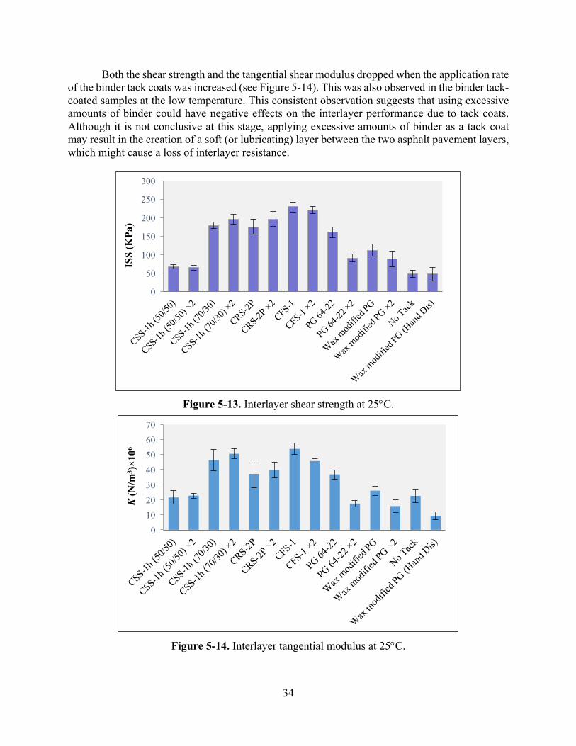
Both the shear strength and the tangential shear modulus dropped when the application rate of the binder tack coats was increased (see Figure 5-14). This was also observed in the binder tack-coated samples at the low temperature. This consistent observation suggests that using excessive amounts of binder could have negative effects on the interlayer performance due to tack coats. Although it is not conclusive at this stage, applying excessive amounts of binder as a tack coat may result in the creation of a soft (or lubricating) layer between the two asphalt pavement layers, which might cause a loss of interlayer resistance.
Figure 5-13. Interlayer shear strength at 25°C.
Figure 5-14. Interlayer tangential modulus at 25°C.
0
50
100
150
200
250
300
ISS
(KPa
)
010203040506070
K(N
/m3 )×1
06

35
Figures 5-15 and 5-16 present the test results at 60°C. The variability of the test results was typically higher than the test results at the low and intermediate temperatures. In general, based on the ISS results, CFS-1 at double application rate and PG 64-22 with standard coverage exhibited the best shear-resistant behavior. Similar to the trend observed at low and intermediate testing temperatures, both the ISS and K values decreased as the application rate increased from standard coverage to double coverage when the binder tack coat was used. It can also be noted that the interlayer bond resistance generally dropped at all temperatures when the wax modified binder at a standard application rate was used as a tack coat. However, no consistent behavior was found when the wax modified binder was applied at double application rate as bond strength increased in the subsection at 60°C, decreased at 5°C, and remained almost the same at 25°C.
Figure 5-15. Interlayer shear strength at 60°C.
0
2
4
6
8
10
12
ISS
(kPa
)

36
Figure 5-16. Interlayer tangential modulus at 60°C.
To compare the performance of the tack coat materials by considering the results from all
three temperatures in a more visual manner, the average maximum shear forces obtained from the direct shear test at each temperature were normalized to a scale of 1 to 5. The outcome was then sorted (as shown in Figure 5-17). The combined averages of the normalized maximum force for the three different temperatures were grouped into five based on the percentage calculated from the highest value (i.e., 4.85 kN). Overall, the best performing group was found from three cases: CFS-1 at double application rate, CRS-2P at double application rate, and CFS-1 at the standard application rate. The current conventional practice in Nebraska (CSS-1h (50/50)) was in the 4th group, and the case without the tack coat was in the worst-performing group (5th).
Figure 5-17. Ranking of tack coats based on average normalized value.
0
1
2
3
4
5
K (N
/m3 )×1
06
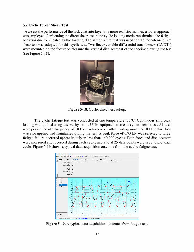
37
5.2 Cyclic Direct Shear Test To assess the performance of the tack coat interlayer in a more realistic manner, another approach was employed. Performing the direct shear test in the cyclic loading mode can simulate the fatigue behavior due to repeated traffic loading. The same fixture that was used for the monotonic direct shear test was adopted for this cyclic test. Two linear variable differential transformers (LVDTs) were mounted on the fixture to measure the vertical displacement of the specimen during the test (see Figure 5-18).
Figure 5-18. Cyclic direct test set-up.
The cyclic fatigue test was conducted at one temperature, 25°C. Continuous sinusoidal
loading was applied using a servo-hydraulic UTM equipment to create cyclic shear stress. All tests were performed at a frequency of 10 Hz in a force-controlled loading mode. A 50 N contact load was also applied and maintained during the test. A peak force of 0.75 kN was selected to target fatigue failure occurred approximately in less than 150,000 cycles. Both force and displacement were measured and recorded during each cycle, and a total 25 data points were used to plot each cycle. Figure 5-19 shows a typical data acquisition outcome from the cyclic fatigue test.
Figure 5-19. A typical data acquisition outcomes from fatigue test.

38
To characterize the fatigue resistance of each tack coat interface, the average from two displacements measured by the two LVDTs was used to determine the fatigue failure. Two main parameters were considered to signify interlayer fatigue failure. The first criterion selected in this study to characterize interlayer fatigue failure resistance was permanent shear deformation (PSD). The average accumulated shear deformation acquired from the two LVDTs was recorded during the test and reported as a PSD value. Figure 5-20 presents the typical relationship between PSD and the number of loading cycles. The PSD graph usually consists of three regions (i.e., primary, secondary, and tertiary), as shown in the figure. In the primary region, permanent deformation grows fast. Then, the rate decreases to a constant value in the secondary region. Finally, the tertiary region shows a dramatic increase in the rate of accumulated deformation.
Figure 5-20. PSD vs. loading cycles.
The number of loading cycles at which tertiary flow begins was selected as the failure point
in the PSD graph. This point is also referred as the Flow Number (FN). Different models have been proposed for identifying the FN, including the smoothed central difference model and the Francken model. The Francken model was proposed at Arizona State University in 1997 and is considered a more reliable approach for computing the deformation rate and the corresponding FN because it combines both a power model to characterize the primary and secondary stages and an exponential model to fit the tertiary stage. The FN is found by differentiating the permanent strain from the loading cycle curve and searching for the minimum value. The Francken model adopted in this study is expressed as follows: up = AnB + C(eDn-1) where up is the permanent shear deformation, n is the number of cycles, and A, B, C, and D are fitting coefficients.
The fitting coefficients are determined using a nonlinear regression method. For example, the cyclic test results of the PSD vs. the loading cycles for subsection #11 and its corresponding curve fit based on the Francken model is depicted in Figure 5-21. As seen in the figure, the model precisely followed the test results.
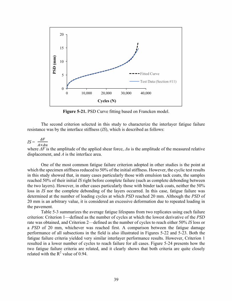
39
Figure 5-21. PSD Curve fitting based on Francken model.
The second criterion selected in this study to characterize the interlayer fatigue failure
resistance was by the interface stiffness (IS), which is described as follows: IS =
,-.×,0
where ΔF is the amplitude of the applied shear force, Δu is the amplitude of the measured relative displacement, and A is the interface area.
One of the most common fatigue failure criterion adopted in other studies is the point at
which the specimen stiffness reduced to 50% of the initial stiffness. However, the cyclic test results in this study showed that, in many cases particularly those with emulsion tack coats, the samples reached 50% of their initial IS right before complete failure (such as complete debonding between the two layers). However, in other cases particularly those with binder tack coats, neither the 50% loss in IS nor the complete debonding of the layers occurred. In this case, fatigue failure was determined at the number of loading cycles at which PSD reached 20 mm. Although the PSD of 20 mm is an arbitrary value, it is considered an excessive deformation due to repeated loading in the pavement.
Table 5-3 summarizes the average fatigue lifespans from two replicates using each failure criterion: Criterion 1—defined as the number of cycles at which the lowest derivative of the PSD rate was obtained, and Criterion 2—defined as the number of cycles to reach either 50% IS loss or a PSD of 20 mm, whichever was reached first. A comparison between the fatigue damage performance of all subsections in the field is also illustrated in Figures 5-22 and 5-23. Both the fatigue failure criteria yielded very similar interlayer performance results. However, Criterion 1 resulted in a lower number of cycles to reach failure for all cases. Figure 5-24 presents how the two fatigue failure criteria are related, and it clearly shows that both criteria are quite closely related with the R2 value of 0.94.
0
5
10
15
20
0 10,000 20,000 30,000 40,000
PSD
(mm
)
Cycles (N)
Fitted Curve
Test Data (Section #11)

40
Table 5-3. Fatigue Test Results
Section Number of Cycles to Failure
Criterion 1 Criterion 2 Sample 1 Sample 2 Average Sample 1 Sample 2 Average
1 CSS-1h (50/50) 20,961 9,041 15,001 36,001 18,833 27,417 2 CSS-1h (50/50) × 2 9,905 6,609 8,257 15,857 10,337 13,097 3 CSS-1h (70/30) 19,897 11,635 27,588 33,015 22,161 27,588 4 CSS-1h (70/30) × 2 24,085 33,217 27,062 41,777 55,489 46,348 5 CRS-2P 17,537 19,553 18,545 30,241 32,001 31,121 6 CRS-2P × 2 26,785 26,849 26,817 49,249 49,761 49,505 7 CFS-1 40,321 41,217 40,769 79,361 89,473 84,417 8 CFS-1 × 2 25,153 32,321 28,737 45,761 48,929 47,345 9 PG 64-22 31,809 19,489 25,649 53,601 35,873 44,737
10 PG 64-22 × 2 24,961 17,857 21,409 27,553 20,097 42,393 11 Wax modified PG 15,878 3,241 9,560 31,046 8,089 23,905 12 Wax modified PG × 2 3,633 3,321 3,477 8,337 5,409 10,911 13 No Tack 1,751 1,911 1,831 2,407 3,633 3,020
14 Wax modified PG (Hand Dis) × 2 1,921 1,533 1,727 3,757 3,785 6,500
Figure 5-22. Average fatigue results: Criterion 1.
0
10,000
20,000
30,000
40,000
50,000
Cyc
les t
o fa
ilure
(FN)

41
Figure 5-23. Average fatigue results: Criterion 2.
Figure 5-24. Relationship between two fatigue failure criteria.
The cyclic fatigue test results show that CFS-1 at the standard application rate (i.e.,
subsection #7) had noticeably better performance than other subsections. Moreover, CSS-1h at a 30% dilution rate, CRS-2P at double application rate, CFS-1 at double application rate, and PG 64-22 with standard coverage had very similar fatigue behaviors. The subsection without the tack coat and both the subsections coated with the wax modified PG 64-22 exhibited poor resistance to fatigue loading. Another notable finding from the cyclic fatigue testing was that, with the exception of the subsection coated with PG 64-22 at a standard application rate, all subsection samples coated with asphalt binder reached failure by exceeding 20 mm PSD, not based on the IS criterion (i.e.,
0
20,000
40,000
60,000
80,000
100,000
Cyc
les t
o fa
ilure
R² = 0.96
0
15,000
30,000
45,000
60,000
75,000
90,000
0 5,000 10,000 15,000 20,000 25,000 30,000 35,000 40,000 45,000
Cyc
les t
o Fi
lure
Cri
teri
on 2
Cycles to Filure Criterion 1

42
50% loss), which implies that in those cases with the asphalt binder tack coat, the interlayer shear strength between the two layers may still remain even after significant deformation. However, all the other subsections (containing emulsified tack coats) presented 50% loss in the IS right before the two layers’ complete debonding. 5.3 Relationship between Monotonic DST and Cyclic (Fatigue) DST
Figure 5-25 depicts the performance ranking of all the subsections from the monotonic DST with the cyclic (fatigue) DST. Since the number of cycles that led to failure were lower for Criterion 1 than for Criterion 2 in all subsections, to sort the performance of tack coat materials, the Criterion 1 (based on FN) was used for the fatigue test ranking, and the maximum shear force was used for the monotonic ranking. Figure 5-25 shows that both test methods provided similar performance rankings in terms of the best and worst cases. The two best cases were sections #7 and # 8, and the two worst cases were sections #13 and #14, and the rank orders were identical in both the tests. However, for the other subsections, the two methods presented somewhat different ranking results.
Figure 5-25. Comparison between monotonic and fatigue in performance ranking.
The linkage between the tack coat performance results obtained from the two different tests
(monotonic DST and cyclic DST) are presented in Figure 5-26. The figure depicts the correlations between the interlayer maximum shear force (from the monotonic DST) and the fatigue failure criteria (from the cyclic DST). The linkage resulted in a higher correlation between the monotonic test results and Criterion 1 (R2 value of 0.75) than with Criterion 2 (R2 value of 0.67). Figure 5-27 illustrates the linkage between the two different tests by relating the interlayer tangential modulus and each fatigue failure criterion. The tangential modulus showed a weaker linkage than the interlayer maximum shear force with fatigue failure. As shown, the R2 values of 0.67 and 0.58 were found with each fatigue failure criterion.
010000200003000040000
7846910531112121314
Cycles to PSD Failure Se
ctio
n0 1 2 3 4
7864359
111012
12
1314
Max Shear Force (kN)
Sect
ion

43
(a)
(b)
Figure 5-26. Correlation between maximum shear force and fatigue test results.
R² = 0.75
0
1
2
3
4
5
0 10,000 20,000 30,000 40,000
Max
imum
She
ar F
orce
(kN
)
Flow Number (Criterion 1)
R² = 0.67
0
1
2
3
4
5
0 20,000 40,000 60,000 80,000
Max
imum
She
ar F
orce
(kN
)
Cycles to Failure (Criterion 2)

44
(a)
(b)
Figure 5-27. Correlation between tangential modulus and fatigue test results.
The initiation and evolution of fatigue damage is strongly related to the amount of strain
or deformation caused by loading on the pavement interlayer. Therefore, another parameter; the area beneath the load-displacement curve until the peak (Figure 5-28) from the monotonic shear test, was also assessed. This parameter, which is denoted as an “interlayer bond energy” in this study, accounts for not only the maximum shear force in the interlayer but also the displacement associated. It also represents the amount of energy dissipated during the stage where the interlayer resists to shearing loading. Thus, it might be interesting to compare this parameter to the fatigue damage results. Analysis results are presented in Figure 5-29. As shown, the interlayer bond energy was better correlated with the fatigue failure criteria than the interlayer shear strength and the tangential shear stiffness. The R2 values were around 0.8. It appears that the interlayer bond energy from the monotonic shear test is a good (or better) parameter for the prediction of the fatigue-related shear resistance of the tack coats based on its higher correlation with the fatigue test results.
R² = 0.67
0
10
20
30
40
50
60
0 10,000 20,000 30,000 40,000
k (N
/m3 )×1
06
Flow Number (Criterion 1)
R² = 0.58
010203040506070
0 20,000 40,000 60,000 80,000
k (N
/m3 )×1
06
Cycles to Failure (Criterion 2)
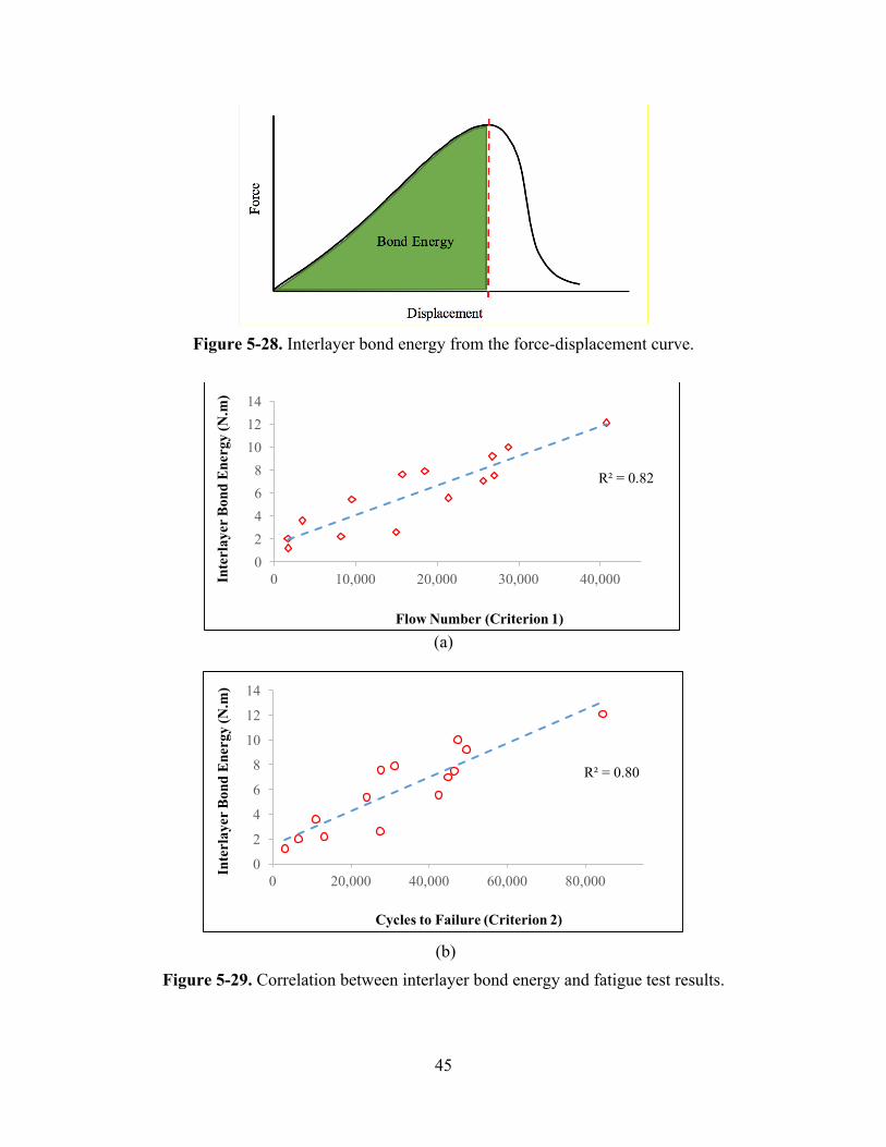
45
Figure 5-28. Interlayer bond energy from the force-displacement curve.
(a)
(b)
Figure 5-29. Correlation between interlayer bond energy and fatigue test results.
R² = 0.82
02468
101214
0 10,000 20,000 30,000 40,000Inte
rlay
er B
ond
Ene
rgy
(N.m
)
Flow Number (Criterion 1)
R² = 0.80
0
2
4
6
8
10
12
14
0 20,000 40,000 60,000 80,000
Inte
rlay
er B
ond
Ene
rgy
(N.m
)
Cycles to Failure (Criterion 2)

46
CHAPTER 6 SUMMARAY AND CONCLUSIONS
The primary objective of this research was to evaluate the engineered tack coating practices in Nebraska. An experimental approach was adopted to investigate the performance of different tack coating strategies. Various tack coat materials, including slow-setting, rapid-setting, and fast-setting emulsified asphalt as well as asphalt binder, were selected, and their performance at different application and dilution rates was evaluated. In the first part of this study, laboratory-prepared samples were used to evaluate the sensitivity and effectiveness of the direct shear testing (DST) method, which was used to characterize the interlayers with treated tack coats. Then, three types of emulsified asphalt and a PG binder, PG 64-22, were applied at different application rates to a field-test section. The DST was performed under monotonic loading conditions at three different testing temperatures. In addition, the fatigue DST using cyclic loading at an ambient temperature was conducted. The testing parameters obtained from the two tests (i.e., monotonic DST and cyclic fatigue DST) were compared to evaluate the performance and damage resistance potential of the different tack coating practices evaluated in this study. Based on the test-analysis results, the following conclusions can be drawn:
• Testing in different temperatures revealed that temperature substantially affected the resistance of the tack coats, and different interlayer behaviors were observed at different temperatures. The samples tested at low temperatures displayed a sudden drop in force after peak, as opposed to the gradual drop of force observed at intermediate temperatures;
• The effect of milling significantly enhanced the interlayer shear strength; however, due to the rough failure surface caused by milling, testing on samples with non-milled surfaces seemed to better capture the effect of the tack coats on the interlayer shear;
• No significant difference was observed between the CSS-1 and CFS-1 emulsions in terms of breaking time. Moreover, as expected, higher application rates resulted in longer breaking times in both the laboratory and field samples;
• Among the emulsified tack coats tested in this study, CSS-1h at a 30% dilution rate showed the longest breaking time in the field, and CRS-2Pshowed the shortest breaking time;
• Based on the DST results of the asphalt binder tack coats at all three temperatures, both the shear strength and tangential modulus dropped as the application rate rose from standard coverage to double coverage, which implies that using more binder than needed could have negative effects on the interlayer performance, but this is not conclusive at this stage;
• Based on the test results from both the monotonic and cyclic tests, CFS-1 and CRS-2P at double application rate (i.e., 0.16 gal/yd2 residual application rate) and the CFS-1 at the standard application rate (i.e., 0.08 gal/yd2 residual application rate) showed superior interlayer performance when compared to the other cases;
• The fatigue and monotonic DST results at 25°C showed an acceptable correlation with regard to the maximum shear force, and the interlayer bond energy, which can also be identified from the monotonic shear test, is a good (or better) parameter for the prediction of the fatigue-related shear resistance of the tack coats based on its higher correlation with the fatigue test results;
• Although the straight binders or wax modified binders did not turn out as top performers, NDOR continues to research trackless tack with binders and adjusting the application rates downward as other states are using and having positive results at lower application rates.

47
References AASHTO TP 114-16, Provisional Standard Method of Test for Determining the Interlayer Shear Strength (ISS) of Asphalt Pavement Layers. American Association of State and Highway Transportation Officials, 2016.
AASHTO M 140-16, Standard Specification for Emulsified Asphalt. American Association of State and Highway Transportation Officials, 2016.
AASHTO M 208-16, Standard Specification for Cationic Emulsified Asphalt. American Association of State and Highway Transportation Officials, 2016.
"The Asphalt Handbook. Manual Series No. 4 (MS-4), 1989 edition." The Asphalt Institute, Lexington, KY.
ASTM D8-02, Standard Terminology Relating to Materials for Roads and Pavements, Annual Book of ASTM Standards, Vol. 04.03, 2004.
Standard Specifications for Highway Construction, (2007). Nebraska Department of Roads.
Proper Tack Coat Application, (2001). Technical Bulletin, Flexible Pavement of Ohio, Columbus, OH.
Biligiri, K. P. (2005). Improved Method to Determine Tertiary Flow for Asphalt Mixtures, Master's Thesis, Arizona State University, Tempe AZ.
Chaignon, F., and Roffe, J.-C. (2001). "Characterization Tests on Bond Coats: Worldwide Study, Impact, Tests, Recommendations." Canadian Technical Asphalt Association. Toronto, Canada.
Choi, Y., A.C, C., Airey, G., and Elliott, R. (2005). "A Comparison Between Interface Properties Measured Using the Leutner Test and The Torque Test." Journal of Association of Asphalt Paving Technologists.
Deysarkar, I. (2004). Test Set-Up to Determine Quality of Tack Coat, Master’s Thesis, The University of Texas at El Paso.
Donovan, E. P., Al-Qadi, I. L., and Loulizi, A. (2000). "Optimization of Tack Coat Application Rate for Geocomposite Membrance on Bridge Decks." Transportation Research Record, pp. 143-150.
Francken, L. (1997). "Pavement Deformation Law of Bituminous Road Mixes in Repeated Load Triaxial Compression" Proc., 4th International Conference on the Structural Design of Asphalt Pavements. University of Michigan, Ann Arbor.
Johnson, E. N., Cole, M. K., and Pantelis, J. (2015). Tack Coat Testing – Measuring Field Bond Strength. Minnesota Department of Transportation.
Mohammad, L. N., Elseifi, M. A., Bae, A., Button, J., and Scherocman, J. A. (2012). Optimization

48
of Tack Coat for HMA Placement, NCHRP REPORT 712., Transportation Research Board, Washington, D.C.
Park, H. J. (2013). Investigation of Primary Causes of Load-Related Cracking in Asphalt Concrete Pavement in North Carolina, Ph.D. dissertation, North Carolina State University, Raleigh, NC.
Paul, H. R., and Scherocman, J. A. (1998). "Friction Testing of Tack Coat Surfaces." Transportation Research Record, pp. 6–12.
Roffe, J. C., and Chaignon, F. (2002). "Characterization Tests on Bond Coats: Worldwide Study, Impact, Tests, Recommendations." 3rd International Conference on Bituminous Mixtures and Pavements. Thessaloniki, Greece.
Romanoschi, S. A., and Metcalf, J. B. (2001). "Characterization of Asphalt Concrete Layer Interfaces." Transportation Research Record, pp. 132-138.
Salam, Y. M., and L, M. C. (1973). "Fracture (Ultimate Strength) Analyses of Asphalt Pavement Layers Resulting from Traffic Loading." Highway Research Record 466, pp. 127–138.
Shahin, M., Kirchner, K., and Blackmon, E. W. (1987). "Analysis of Asphalt Concrete Layer Slippage and Its Effect on Pavement Performance and Rehabilitation Design" 6th International Conference on the Structural Design of Asphalt Pavements. University of Michigan, Ann Arbor.
Shahin, M., Van Dam, T., Kirchner, K., and Blackmon, E. W. (1987). Consequence of Layer Separation on Pavement Performance. Report DOT/FAA/PM-86/48. Federal Aviation Administration, U.S. Department of Transportation.
Sholar, G. A., Page, G. C., Musselman, J. A., Upshaw, P. B., and Moseley, H. L. (2002). Preliminary Investigation of a Test Method to Evaluate Bond Strength of Bituminous Tack Coats. Research Report, Florida Department of Transportation.
Sutanto, M. H. (2009). Assessment of Bond Between Asphalt Layers, Thesis submitted for the degree of Doctor of Philosophy, Nottingham Transportation Engineering Center.
Tashman, L., Nam, K., and Papagiannakis, T. (2006). Evaluation of The Influence of Tack Coat Construction Factors on The Bond Strength Between Pavement Layers. Washington State Department of Transportation.
Tayebali, A. A., Rahman, M. S., Kullkarni, M. B., and Xu, Q. (2004). A Mechanistic Approach to Evaluate Contribution of Prime and Tack Coat In Composite Asphalt Pavements. Final Report, FHWA/NC/2004-05, North Carolina Department of Transportation, Department of Civil Engineering, North Carolina State University.
Walsh, I. D., and Williams, J. T. (2001). "HAPAS certificates for procurement of thin surfacing". Highways and Transportation.
West, R. C., Zhang, J., and Moore, J. (2005). Evaluation of Bond Strength Between Pavement Layers. National Center for Asphalt Technology (NCAT).

49
Zare Rami, K., and Kim, Y. R. (2015). Nebraska Data Collection. Nebraska Department of Roads (NDOR).