evaluation of safety in a petroluem refining company: a ... · pdf filean oil refinery or...
TRANSCRIPT

IOSR Journal Of Environmental Science, Toxicology And Food Technology (IOSR-JESTFT)
e-ISSN: 2319-2402,p- ISSN: 2319-2399. Volume 3, Issue 5 (Mar. - Apr. 2013), PP 68-82 www.Iosrjournals.Org
www.iosrjournals.org 68 | Page
Evaluation of Safety in a Petroluem Refining Company:
A Case Study on the Naphtha Hydro – Treating Unit (Nhu) Of
Kaduna Refining and Petrochemical Company, Nigeria
1Otaru, A.J.,
2Abdulkareem, A.S.,
3Yusuf, Y.R.,
4Odigure, J.O.,
5Okafor, J.O. and
6Ibrahim, S.
1,2,3,4&5(Department of Chemical Engineering, Federal Univeristy of Technology, PMB 065, Gidan Kwanu,
Minna, Niger State, Nigeria) 6(Ovecon Engineering and Consultancy, P.O. Box 1730, Zaria, Nigeria)
(Published in honor of Jacqueline C. Schindler)
Abstract: This research work is concerned with the evaluation of safety in a petroleum company (A case study
on the Naphtha Hydro – treating Unit NHU of Kaduna Refining and Petrochemical Company, Nigeria). The
evaluation was done using the formal safety review method which analyzes operation parameters such as
temperatures of process equipment in actual operation with respect to temperature on the process flow diagram,
and emissions like noise for a period of one year. The result shows that the major hazards in the NHU are heat
emissions from process equipments like heaters and heat exchangers with emissions of poisonous gases such as
H2S, NH3 and traces of heavy metal. The result also shows that the atmospheric condition at different months of
the year has an adverse effect on the temperature of process equipment. This result also confirms that for most
process industries like refineries, petroleum companies, and production companies, are associated with such hazards.
Keywords: Hazards, Kaduna, NHU, Refining, and Safety.
I. Introduction The Nigerian economy depends heavily on income from crude oil exportation and the refined petroleum
products to power industries for local consumption within Nigeria, in fact, it is a well known fact that the West
African region relies to a great extent on Nigerian refined petroleum to oil their economy. It is also a fact that
whenever refineries in Nigeria go down, a lot of hardship is experienced occasionally by long fuel queues in
filling stations to outright unavailability of the product.
An oil refinery or petroleum refining industry is an industrial process plant where crude oil are been
processed and refined into more useful petroleum products, such as gasoline, diesel, asphalt base, heating oil, and liquefied petroleum gas (Gary and Handwerk,1984). Oil refineries are typically large, sprawling industrial
oil complexes with the extensive piping running throughout carrying streams of fluid between large chemical
processing units (Leffler, 1985). In many ways oil refineries use much of the technology and can be thought of
as type of chemical plant. In terms of operations, raw or unprocessed crude oil is not generally useful in
industrial applications, although „light sweet‟ (low viscosity, low sulphur) crude oil has been used directly as a
fuel for steam vessel propulsion.
Naphtha is a colorless reddish brown volatile aromatic liquid, very similar to gasoline which also, is a
fraction of crude oil that contains a number of flammable mixtures of hydrocarbon. It is a broad term covering
among the lightest and most volatile fractions of the liquid hydrocarbon in petroleum (Prestvic, et al., 2004). In
petroleum engineering, full range naphtha is defined as the fraction in petroleum boiling between 30oC and 200o
C and consists of a complex of hydrocarbon molecules generally having between 1 and 12 carbon atoms, it
typically constitute 15 - 30℅ crude oil by weight, light naphtha is a fraction boiling between 30oC and 90oC and consist of molecules with 5 – 6 carbon atoms. Heavy naphtha boils between 90oC and 200oC and consists of
molecules with 6 – 12 carbons (Prestvic, et al., 2004). The purpose of the naphtha hydro-treating unit is to
eliminate the impurities (such as sulphur, nitrogen, halogens, oxygen, water, olefins, di-olefins, arsenic and
metal) form the feed that would otherwise affect the performance and lifetime of the reformer catalyst (Chiyoda,
1980). This is achieved by the use of selected catalyst like nickel, cobalt and molybdenum at optimum operating
conditions except for water which is eliminated in stripper.
The hazardous nature of naphtha in the refinery (NHU) can be minimized or reduced by the provision
of exhaust ventilation or other engineering controls to keep the airborne concentrations of the vapor below their
respective threshold limit value and also ensuring that eyewash stations and safety showers are proximal to the
work - station location (Sadighi et al., 2009) . Also in the case of large spill of naphtha, use of personal
protective equipments such as splash goggles, full suit, gloves, vapor respirator, a self contained breathing

Evaluation Of Safety In A Petroluem Refining Company: A Case Study On The Naphtha Hydro –
www.iosrjournals.org 69 | Page
apparatus should be used to avoid inhalation of the product. The time weighted average (TWA) of whole
naphtha depends on the location where it is being used.
Due to the sensitive nature and high risk associated with refineries, the importance of safety cannot be overemphasized. A lot of loss in production has been experienced due to downtime damage and injuries. Also,
the rigorous operations carried out in the naphtha hydro – treating unit, have exposed workers to hazards that
pose treat to human health system. It is against this background that it is of immense important to evaluate these
hazards and how they can be managed effectively so that workers can have a safe working environment. This
work is focused on the safety evaluation in a petroleum refining company. The major objective of this research
include investigating the safety in the Naphtha Hydro – treating Unit in the petrochemical industry particularly
in the Southern part of Kaduna, Nigeria to determine the current state of hazards and how it can be minimized.
II. Research Methodology The method of evaluating safety in the naphtha hydro treating unit of the Kaduna Refining and
Petrochemical Company in this research work is based on the approach of “the formal safety review process”.
The required information were extracted from the process flow diagram (PFD) and the NHU operating manual
and tabulated as shown in Table 1. It also involves collection of process parameters such as temperature, and
flow rate in actual operations for a period of one year. This is done in order to compare the deviation of the
temperatures of process equipment and that in the process flow diagram so as to evaluate the difference in the
heat emitted from each of the process equipment and also relate the hazardous effect on the health of the
workers in the Naphtha Hydro – treating Unit plant. This research also involves collection of data of noise
pollution within the above mentioned period in order to evaluate the Time Weighed average (TWA) at which
the Kaduna Refining and Petrochemical Company operates and relating the K.R.P.C value with the Time
Weighted Average of the Occupational Safety and Health Administration (OSHA) of the United states Department of Labor (USDL).
Table 1: NHU Stream Data Extracted from Process Flow Diagram (PFD).
S/NO. Stream No. Stream Name Heat Duty (Kcal/hr) ×106
1 11E01A-C NHU Feed/Effluent exchanger 24.16
2 11H01 NHU Reactor Charge Heater 6.38
3 11R01 NHU Reactor Effluent 24.16
4 11A01 NHU Reactor Effluent Cooler 5.39
5 11E02 NHU Reactor Effluent Trim Cooler 0.52
6 11E05 NHU Low Pressure Separator Charge cooler
0.35
7 11C01 NHU Stripper Feed 6.41
8 11E03 NHU Stripper Feed Bottom Exchanger
6.41
9 11A02 NHU Stripper OH Condenser 4.39
10 11E04 NHU Stripper OH Trim Condenser 0.56
11 11H02 NHU Stripper Reboiler heater 14.70 12 11C02 NHU Splitter 14.70 13 11E06 NHU Splitter Reboiler 4.28 14 11A03 NHU Splitter OH Condenser 5.09 15 11E07 NHU Light Naphtha Trim Cooler 0.23
16 11A04 NHU Heavy Naphtha Cooler 2.10
`17 11E04 NHU Stripper OH Trim Condenser 0.17
Formal Safety Review Process
The formal safety review is used for new process, substantial changes in existing processes, and processes that
need an updated review. The formal safety review is a three – step procedure. Which consist of:
1. Preparing a detailed formal safety review report.
2. Having a Committee to review the report and inspect the process
3. Implementing the recommendations

Evaluation Of Safety In A Petroluem Refining Company: A Case Study On The Naphtha Hydro –
www.iosrjournals.org 70 | Page
Description of the Naphtha Hydro – treating based on formal safety review method. Stage I: Introduction Overview or summary: This will be done at the end of the of the formal safety review process of the Naphtha Hydro - treating Unit. It is based on the results obtained from the analysis of temperature, emissions of
chemicals such ammonia, H2S, traces of heavy metals like Lead, arsenic, copper and noise pollution.
Process overview: The Naphtha Hydro - treating Process is a catalytic refining process employing a selected
catalyst and a hydrogen-rich gas stream. Decompose organic sulphur, oxygen and nitrogen compounds
contained in hydrocarbon fractions. In addition, hydro - treating removes Organo - metallic compounds and
saturates olefinic compounds.
Operation of these units involves the coordination of different activities to be carried out in an efficient and safe
manner. It also requires a detailed knowledge of the process, proper planning, safe plant operation, effective
supervision and monitoring.
Figure 1: The Formal Safety Review Steps Diagrammatical Representation
The major operation of the Naphtha Hydro – treating Unit involves;
1. Removal of impurities by reaction with hydrogen
2. Separation of Whole naphtha into its fractions.

Evaluation Of Safety In A Petroluem Refining Company: A Case Study On The Naphtha Hydro –
www.iosrjournals.org 71 | Page
1. Impurities Contained in whole Naphtha are;
i. Sulfur in form of mercaptans, sulfides, disulfides, thiophenes etc.
ii. Nitrogen in the form of pyrroles, pyridines. iii. Oxygen in the form of phenols, diphenols.
iv. Metals such as Lead ,Copper, Iron, Nickel ( Organo – metallic compounds)
2. Fractions obtained from whole naphtha separation in NHU
i. Liquefied Petroleum Gas.
ii. Light Naphtha.
iii. Heavy Naphtha.( Treated)
Reaction and stoichiometry
The reactions taking place in the NHU are grouped into two types, thus:
Hydrogenation reactions: This consists mainly of saturation of Olefinic compounds and in the saturation of Aromatic Compounds. Olefins are unsaturated hydrocarbons having the general formula CnH2n and are
characterized by relatively great chemical activity (unstable structure). They tend to polymerize or in the
presence of hydrogen become saturated compounds or paraffinic compound. The presence of olefins in the feed
is negligible. Aromatics are ring compounds characterized by alternate double bond. In the presence of
hydrogen they tend to turn into naphthenic compounds. Under normal conditions these reactions are generally
weak, however pressure favors them. These reactions must be avoided so as to avoid an increase of the work
load of the reforming catalyst.
Hydro – refining reactions: These reactions are related to the desulfurization, denitrification, deoxygenation,
and demetalization of the feed (whole naphtha).
Desulfurization reaction: This is a hydro – refining reaction in which sulphur compounds are transformed into hydrogen sulphide and hydrocarbon compound. The sulphur compounds of straight – run naphtha are mainly
mercaptan, sulphides, disulfides, and polysulphides which can be easily transformed. These reactions are
illustrated below:
R – SH + H2 RH + H2S. (General equation for the reaction).
Mechanism for the general equation of reaction.
RS R* + S*
R* + S* + H2 R H + H2S
CH3 – CH2 – CH2 – CH2 – CH2 – SH +H2 C5 H12 + H2S
Amylmercaptan n – pentane + Hydrogen sulphide
CH3 – CH2 – CH2 – S – S – CH2 – CH2 – CH3 + 3H2 2C3H8 + 2H2S
Dipropyldisulfide Propane + Hydrogen sulphide
It is more difficult to eliminate the sulphur contained in cyclic compounds of aromatic character like thiophenes,
etc.
CH CH
CH CH + 4H2 C4H10 + H2S Butane + Hydrogen sulphide
S
Desulphurisation reactions are exothermic, thus 17 to 67Kcals for each mole of hydrogen
Denitrification reaction: This is a hydro – refining reaction by which nitrogen compounds are transformed into ammonia and hydrocarbon. The nitrogen compounds are mainly pyrroles, pyridines which have a cyclic
structure with an aromatic character and are decomposed at lower rate than the desulphurization reactions.
Nevertheless nitrogen elimination is practically completely achieved. This is illustrated below;

Evaluation Of Safety In A Petroluem Refining Company: A Case Study On The Naphtha Hydro –
www.iosrjournals.org 72 | Page
De – oxygenation reaction: This is a hydro – refining reaction by which oxygen compound are transformed into
water and hydrocarbon compounds. These oxygen compounds are mainly phenols. Phenols are cyclical
compounds derived from benzene by substituting an atom of hydrogen with an hydroxyl. This is illustrated
below;
De – metallization reaction: This is reaction where by metals present in the feed (whole naphtha) are associated
with hydrocarbons and their removal is obtained by replacement with hydrogen. Metals released are in pure
form and are absorbed by the catalyst support (alumina). Generally metals favors cracking with consequent
deposition of coke, but due to their minute quantities in the hydro – treated feedstock, they are not considered a
problem for the running of the unit. However the catalyst has a very high metal absorption capacity. This is
illustrated below;
PbR + H2 RH + Pb
Engineering data: The operating parameters for the naphtha hydro treating unit is; Temperatures, Pressures
Flow rates and relevant physical property data for the NHU
Stage II Raw material and products.
The raw material handled in the Naphtha hydro – treating unit is mainly whole naphtha or straight – run
naphtha. At the end of the process, Liquefied Petroleum Gas (LPG), Light Naphtha and treated Heavy Naphtha
are obtained. The hazards associated with the NHU plant are listed below:
a. Emission Hazard.
b. Fire and exposure hazard.
c. Noise pollution. d. Mechanical failure etc.
Emission hazards
Emissions associated with the Naphtha Hydro - treating Unit is as a result of spills and leakages from
pipes, reactors, columns, heaters, and heat exchangers etc. These emissions can be analyzed or evaluated based
on the nature of reactions taking place in the NHU reactor, and impurities such as sulphur, nitrogen, oxygen,
traces of heavy metals to be removed from naphtha which in turn after the reaction are removed in the form of
sulphides, mercaptans, disulphides, thiophenes, pyrroles, pyridines, phenols, diphenoles, lead, iron and nickel to
obtain the desired products, which under normal condition are harmful to the human body mechanism. Table 2
below explains these emissions and how they can be minimized or handled in order to ensure safe working
environment or atmosphere.
Evaluation Of Safety In A Petroluem Refining Company: A Case Study On The Naphtha Hydro –
www.iosrjournals.org 73 | Page
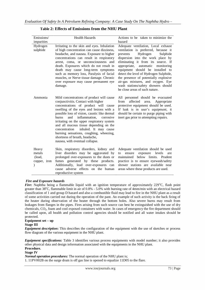
Table 2: Effects of Emissions from the NHU Plant
Emissions/
impurities
Health Hazards Actions to be taken to minimize the
hazard
Hydrogen
sulphide
Irritating to the skin and eyes. Inhalation
of high concentration can cause dizziness,
headache, and nausea. Exposure to higher
concentrations can result in respiratory
arrest, coma, or unconsciousness and
death. Exposures which do not result in
death may cause long-term symptoms
such as memory loss, Paralysis of facial
muscles, or Nerve tissue damage. Chronic over exposure may cause permanent eye
damage.
Adequate ventilation, Local exhaust
ventilation is preferred, because it
prevents Hydrogen Sulphide
dispersion into the work place by
eliminating it from its source. If
appropriate, automatic monitoring
equipment should be installed to
detect the level of Hydrogen Sulphide,
the presence of potentially explosive air-gas mixtures, and oxygen. Eye
wash stations/safety showers should
be close areas of such nature.
Ammonia
Mild concentrations of product will cause
conjunctivitis. Contact with higher
concentrations of product will cause
swelling of the eyes and lesions with a
possible loss of vision, caustic like dermal
burns and inflammation, corrosive
irritating on the upper respiratory system and all mucous tissue depending on the
concentration inhaled. It may cause
burning sensations, coughing, wheezing,
shortness of breath, headache,
nausea, with eventual collapse.
All personnel should be evacuated
from affected area. Appropriate
protective equipment should be used.
If leak is in user‟s equipment, it
should be certain to purge piping with
inert gas prior to attempting repairs.
Heavy
metals
(lead,
copper, iron
)
Skin, respiratory disorders, kidney and
liver disorders may be aggravated by
prolonged over-exposures to the dusts or
fumes generated by these products.
Additionally, lead over-exposures can
cause adverse effects on the human reproductive system
Adequate ventilation should be used
to ensure exposure levels are
maintained below limits. Prudent
practice is to ensure eyewash/safety
shower stations are available near
areas where these products are used.
Fire and Exposure hazards
Fire: Naphtha being a flammable liquid with an ignition temperature of approximately 229oC, flash point
greater than 38oC, flammable limit in air of 0.8% - 5.0% with burning rate of 4mm/min with an electrical hazard
classification of 1 and group D hazard and also a combustible fluid may lead to fire in the NHU plant as a result
of some activities carried out during the operation of the pant. An example of such activity is the back firing of
the heater during observation of the heater through the bottom holes. Also severe burns may result from
leakages from flanges in the pipes. Fires arising from such source can best be extinguished with the use of dry
chemicals, CO2, foam and cool exposed containers with water. In cases of emergency the fire department should
be called upon, all health and pollution control agencies should be notified and all water intakes should be
protected.
Equipment set – up
Stage III
Equipment description: This describes the configuration of the equipment with the use of sketches or process
flow diagram of the various equipment in the NHU plant.
Equipment specifications: Table 3 identifies various process equipments with model number; it also provides
other physical data and design information associated with the equipments in the NHU plant.
Procedure.
Stage IV
Normal operation procedures: The normal operation of the NHU plant is;
1. 11PV002B on the surge drum is off gas line is opened to equalize 11D05 to the flare.

Evaluation Of Safety In A Petroluem Refining Company: A Case Study On The Naphtha Hydro –
www.iosrjournals.org 74 | Page
2. An inventory of naphtha from 51TK92 in 11D05, 11D04, 11C01 and 11C02 and the reboiler
circuit is established.
3. Reboiler circulation is started up. 4. Following the fired heater start – up standing instructions the pilots in 11H02 is lighted.
5. 11A02/03is started when required.
6. 11H02 is fired at40oC/hr and a total reflux is established.
7. Corrosion inhibition injection is started.
8. Heavy naphtha is lined up to 51TK92
9. When CDU naphtha becomes availably cut into the work – up section, light naphtha is lined
up to 51TK12.
10. 11H02 firing and tower conditions are adjusted for steady state operation.
Safety procedures: This provides description of the unique concerns associated with the equipment and
materials and specific procedures used to minimize risk in the NHU plant. This includes:
Emergency shutdown: This describes the procedure used to shutdown the equipment if an emergency should occur in the NHU plant. This includes major leaks, reactor runaway, and loss of electricity, water and air
pressure.
General emergency shutdown procedure
Emergency shutdown is made to maintain the pressure and the liquid level in the equipment at the normal
operating level so that the unit can be restarted easily.
With the following actions, the unit will be in a bottled up condition. Generally the unit can be held in this
condition until the emergency situation is removed, otherwise continue the shutdown of the unit by referring to
the normal shutdown procedure.
For protection of the hydro-treating catalyst, follow these rules when possible:
(a) Avoid too high a temperature of the catalyst.
(b) Avoid having hydrocarbons present on the catalyst when hydrogen partial Pressure is too low.
(c) Avoid too quick depressurizing of the reactor section.
NHU Reactor Section General Emergency Shutdown Procedure
In a case where the NHU makeup gas is stopped or the catalytic reforming unit (CRU) should be shut down
immediately, which cause to cease the hydrogen production, the naphtha hydro-treating unit (NHU) should be
shut down immediately.
(a) Cut off the main fuels to the NHU reactor charge heater (11H01) by turning the manual
stop switch (HS-001).
Figure 2: Process Flow Diagram of the Naphtha Hydro – Treating Unit Plant

Evaluation Of Safety In A Petroluem Refining Company: A Case Study On The Naphtha Hydro –
www.iosrjournals.org 75 | Page
Table 3.3: Equipment Specification of the NHU Plant
Tag
Des
ign
pre
ssure
(kg/c
m2)
Des
ign t
emper
ature
s(oC
)
Hydro
tes
t
pre
ssure
(kg/c
m2)
Siz
e(m
m)
11DO5 3 55 4.5 3000/9000
11D04 14 55 21 2500/6650
11D01 22.1 55 33.2 2200/5750
11C01 17.1 241 25.65 3800/35300
11C02 3 164 4.5 3500/33735
11R01 27.9 385 41.9 2900/3830
11E01A shell side 31.7 170 47.6
11E01A tube side 25.7 221 53.7
11E01B shell side 31.7 224 47.6
11E01B tube side 25.7 271 38.7
11E02 shell side 22.8 120 34.3
11E03 shell side 19.3 153 29.1
11E03 tube side 17.1 241 25.8
11E04 shell side 17.1 86 25.8 11E04 tube side 6 60 9.1
11E05 shell side 14.4 61 21.7
11E05 tube side 6 60 9.1
11E06 shell side 3 164 4.6
11E06 tube side 26.5 241 39.8
11E07 shell side 29 115 43.5
11E07 tube side 6 60 9.1
11E08 shell side 12.5 72 18.8
11E08 tube side 6 60 9.1
Note (1)The pilot burner firing continues.
(2) For any emergency situation which appears as low flow in the NHU makeup gas, the
Main Fuels are automatically cut off by the emergency interlock system.
(3) Isolate main fuel supply and atomizing steam lines. If possible, close burner valves.
(b) At the same time, stop the NHU reactor charge pump (11P01A or B) by pushing the
Manual stop button (HS-002) and close the NHU reactor feed flow control valve (FV-001)
Manually. Close the discharge valve of the pump as early as possible.
Note Divert whole naphtha of the crude distillation unit No. 1 and No. 2 (CDU-1 & CDU-2) to the light slop tank as
early as possible. 1. The CRU reactor charge pump (11P06A or B) have been stopped due to requirement in the catalytic
reforming unit (CRU). Otherwise stop 11P06A or B and close the CRU reactor feed flow control valves
(12FV-014/ 016) manually. Close the discharge valve of the pump as early as possible.
(c) Immediately close the NHU stripper feed flow control valve (FV-011) and stop
the NHU stripper charge pump (11P05A or B).
Close the block valve at FV-011 as early as possible.
(d) Block off the hydrogen rich KHU makeup gas line (3”-GH-11009) at the
Battery limit.
Note
The hydrogen rich NHU makeup gas has been stopped and the pressure control
Valve (PV-010) on the NHU HP separator off-gas line (4”-GH-11007) has to be

Evaluation Of Safety In A Petroluem Refining Company: A Case Study On The Naphtha Hydro –
www.iosrjournals.org 76 | Page
Closed automatically.
(e) Close the NHU HP separator level control valve (LV-002) manually and close the block valve at LV-002.
(f) Watch the NHU reactor bed temperature indicators (TJI-006 ~ 010). If a temperature rise is observed, depressurize the NHU reactor section to the fuel gas system or the flare.
Watch the heater coil skin temperature indicators (TJI-016 ~ 019). If necessary, cut off the pilot fuel to
11H01, put snuffing steam into the firebox and open the stack damper to avoid coil overheating.
NHU work-up section general emergency shutdown procedure
(1) Total Reflux Operation: When the NHU reactor section should be shut down immediately, keep the NHU
stripper and the NHU splitter operating under total reflux, if possible.
(a) Immediately close the NHU splitter feed flow control valve (FV-013) manually.
(b) Close the NHU stripper OH receiver, NHU splitter and NHU splitter OH receiver level control valves (LV-
007/008/009) manually.
(c) Stop the NHU corrosion inhibitor pump (11P07).
(d) Continue the NHU stripper (11C01) and the NHU splitter (11C02) operating under total reflux. (2) Emergency Shutdown
If the NHU work-up section should be shut down immediately, apply the following procedure:
(a) Cut off the main fuels to the NHU stripper re-boiler heater (11H02) by turning the manual stop switch (HS-
003).
Note
The pilot burner firing continues.
Isolate main fuel supply and atomizing steam lines. If possible, close burner valves.
(b) Close the temperature control valve (TV-008) manually to stop oil circulation through the NHU splitter re-
boiler (11E06).
(c) Immediately close the NHU splitter feed flow control valve (FV-013) manually. Close block valve at FV-
013 as early as possible.
(d) Close the NHU stripper OH receiver, NHU splitter and NHU splitter OH Receiver level control valves (LV-007/008/009) manually.
(e) Stop the NHU stripper OH pump (11P03A or B) and the NHU splitter OH pump (11P04A or B).
(f) Stop the NHU corrosion inhibitor pump (11P07).
(g) Continue the re-boiler circulation.
Note
If the re-boiler circulation cannot be maintained, watch the heater coil temperature indicators (TJI-035 ~ 038).
If necessarily, cut-off the pilot fuel to 11H02 put snuffing steam and opens the stack damper to avoid coil
overheating.
Waste disposal Procedure: Most waste generated in the NHU plant is sent to the flare.
Cleanup procedures: Weakly hand picking of dirt around the unit (Housekeeping)
Safety Checklist
Stage V
The following are to be checked before any start is made in the NHU plant;
1. NHU work – up section in – line with feed from CDU. Heavy naphtha run down to 51TK92, light naphtha
to slope.
2. Reactor section air free and under 0.2kg/cm2 N2 with O2 content less than 0.2%.
3. CRU in – line with feed from 51TK01A/B producing sufficient hydrogen.
4. NHU HP separator off – gas lined up to GTU.
III. Results and Discussion The importance of safety in process plant especially in process developing countries like Nigeria cannot
be overemphasized. This is due to the fact that there are no standard practices in place to check the activities of
process industries on the health of workers as compared to developed countries. Aside from the risk that safety
posed on the workers, it is also a source of risk to the physical assets of companies. Hence, there need to
understand and identify the possible root of accidents for the purpose of eliminating or minimizing them.
This study was necessitated by the importance of petroleum as a major source of income to the Nigerian
economy. It is also worth of mentioned that safety is based on the physical mechanics and chemistry attributes
of the plants. The present studies graphically present and discuss the results obtained during the safety evaluation of the Naphtha Hydro – treating Unit NHU of Kaduna Refining and Petrochemical Company,
Nigeria.

Evaluation Of Safety In A Petroluem Refining Company: A Case Study On The Naphtha Hydro –
www.iosrjournals.org 77 | Page
Figure 3 – 14 is the graphical representation of the highest temperature both for inlet, outlet, top and
bottom of NHU equipments for the months of the year 2011. The equipments are heater surge drum (11D05),
reactor charge heater (11H01), NHU reactor (11R01) inlet, NHU reactor (11R01) outlet, feed effluent exchanger (11E01), NHU separator (11D04), NHU stripper(11C01) bottom, stripper (11C01) top, NHU splitter (11C02)
bottom, and the NHU stripper reboiler heater (11H02).
Figure 3: Graph of Highest Temperature (°C) of 11D05 against Months for Year 2011
Figure 4: Graph of Highest Temperature of 11H01 against Months of Year 2011.
Figure 5: Graph of Highest Temperature of 11E01 against Month of Year 2011
48.049.050.051.052.053.054.055.056.057.058.059.0
Hig
hes
t T
emp
eratu
re (C
)
Months of Year of 2011
322
324
326
328
330
Hig
hes
t T
emp
eratu
re (C
)
Months of Year
0.0
50.0
100.0
150.0
200.0
250.0
300.0
Hig
hes
t T
emp
eratu
re (C
)
Months of Year 2011

Evaluation Of Safety In A Petroluem Refining Company: A Case Study On The Naphtha Hydro –
www.iosrjournals.org 78 | Page
Figure 6: Graph of Highest Inlet Temperature of 11R01 against Months of Year 2011
Figure 7: Graph of Highest Outlet Temperature (C) of 11R01 against Months for Year 2011
Figure 8: Graph of Highest Temperature (C) of 11D01 against Months for Year 2011
321
322
323
324
325
326
327
328
Hg
hes
t In
let
Tem
per
atu
re (C
)
Months of Year 2011
320322324326328330332334336338340
Hig
hes
t O
utl
et T
emp
eratu
re
(C
)
Months of Year 2011
0.010.020.030.040.050.060.070.080.0
Hig
hes
t T
emp
eratu
re (C
)
Months of Year 2011

Evaluation Of Safety In A Petroluem Refining Company: A Case Study On The Naphtha Hydro –
www.iosrjournals.org 79 | Page
Figure 9: Graph of Highest Temperature (C) of 11D04 against Months for Year 2011
Figure 10: Graph of Highest Bottom Temperature (°C) of 11C01 against Months of Year 2011
Figure 11: Graph of Highest Top Temperature (°C) of 11C01 against Months for Year 2011
40.0041.0042.0043.0044.0045.0046.0047.0048.0049.0050.00
Hig
hes
t T
emp
ertu
re (C
)
Months of Year 2011
242.0
244.0
246.0
248.0
250.0
252.0
254.0
256.0
258.0
Hig
hes
t T
emp
eratu
re (
C
)
Months of Year 2011
0.0
20.0
40.0
60.0
80.0
100.0
120.0
140.0
Hig
hes
t T
emp
eratu
re (C
)
Months of Year 2011

Evaluation Of Safety In A Petroluem Refining Company: A Case Study On The Naphtha Hydro –
www.iosrjournals.org 80 | Page
Figure 12: Graph of Highest Bottom Temperature (°C) of 11C02 against Months for Year 2011
Figure 13: Graph of Highest Top Temperature (C) of 11C02 against Months for Year 2011
Figure 14: Graph of Highest Temperature (°C) of 11H01 against Months for Year 2011
108.0
110.0
112.0
114.0
116.0
118.0
120.0
122.0
124.0
Hig
hes
t T
emp
eratu
re (C
)
Months of Year 2011…
108.0
110.0
112.0
114.0
116.0
118.0
120.0
122.0
124.0
Hig
hes
t T
emp
eratu
re (C
)
Months of Year 2011
230.0
235.0
240.0
245.0
250.0
255.0
260.0
Hig
hes
t T
emp
eratu
re (C
)
Months of Year 2011

Evaluation Of Safety In A Petroluem Refining Company: A Case Study On The Naphtha Hydro –
www.iosrjournals.org 81 | Page
From the result obtained, it was recorded that the average temperatures for a period of one year of the process
equipments like surge drum (11D05), reactor charge heater (11H01), NHU reactor (11R01) inlet, NHU reactor
(11R01) outlet, feed effluent exchanger(11E01), NHU separator(11D04), NHU stripper(11C01) bottom, stripper (11C01) top, NHU splitter (11C02) bottom, and the NHU stripper reboiler heater (11H02) are 55.1oC, 327.6oC,
324.1 oC, 333.3
oC, 181.3
oC, 55.5
oC, 46.1
oC, 253.3
oC, 94.7
oC, 138.7
oC, 116.38
oC, and 248.4
oC. The
approximate heat duties for 11H01, 11E01, 11D01, 11DO4, 11H02, 11C01, 11C02 and 11R01 were also
recorded as 1.33×10⁸KJ/day, 1.17×10⁹KJ/day, 1.14×10⁸KJ/day, 7.98×10⁷KJ/day, 8.5×10⁸KJ/day, 6.0×10⁸KJ/day,
8.5×10⁷KJ/day, and -2.1×10⁷KJ/day respectively. It is quite obvious that the equipment that constitutes the
major source of heat in the Naphtha Hydro – treating Unit is the heat exchangers and heaters.
NB: Temperature measures the flow of heat energy from one body to another. To a degree, the human body
system generates some of its own heat through the body metabolism.
The exposure of workers to higher temperature process equipment is a hazard to the health of workers in the
sense that the body momentum of the circulatory system changes resulting to heat related illnesses ranging from
minor to a more serious and dangerous conditions of dehydration, heat strokes, skin problems like hyperthermia, skin burns, Azospermia and Oligospermia when the time of exposure is prolonged. Heat stroke is an acute
condition of hyperthermia that is caused by prolonged exposure to excessive heat.
Figure 3 shows the variation in temperature at various months of the year, this variation in temperature can be
said to be attributed to the atmospheric conditions of the year.
Figure 4 gives a clearer view that the heater constitutes one of the major sources of heat emission in the NHU
plant despite the changes in atmospheric condition at stipulated month of the year. Figure 5 shows that for the
first three months of the year, the temperature difference is quite minimal and towards the end of the year the
temperature values were very close. This may be due to the changes in temperature condition of the
environment.
Figure 6 shows that at different months of the year, the inlet temperature is almost constant, which
explains the temperature at which NHU reactor operates. Figure 7 shows a little deviation from the inlet
temperature which may be due to the level of conversion of the reactor feed to product. Figure 8 shows that the highest temperature was obtained during the fifth month of year. Figure 9 illustrates that the highest temperature
was obtained in the month of April which is quite hot based on the weather. Figure 10 indicates that the lowest
and highest temperatures were 248.1oC and 257.2oC during the months of February and May which also
explains the difference in atmospheric conditions at different period of the year and that the stripper bottom
temperature is of a higher one compared to the Figure 11 whose highest temperature was 119oC during the
month of September. Figure 12 and Figure 13 gives the bottom and top temperatures of the splitter and it also
shows that the temperature variation is of a closer range at different periods of the year. Figure 14 shows that the
stripper reboiler (11H02) operates between the temperature ranges of 241.9oC to 256.2oC which is on the high
side.
Noise is an undesirable, unpleasant and untimely sound, which can be continuous or intermittent. It may
also be said that noise depends on the pre-existing physical and psychological state of the individual. Noise pollution affects everyone, yet this problem is largely ignored by most people. Exposures of workers to high
noise level can result to temporary deafness which persists for about 24 hours after exposure to loud noise and
may lead to permanent deafness; decreased work efficiency, increased intracranial pressure if the exposure is
continuous.
The result presented in Table 4 and 5 show that the average noise exposure of the NHU plant was
obtained to be 92.2 dB measured on the a scale for a shift of 12 working hours which is quite higher than the
Occupational Safety and Health Administration (OSHA) of the United States Department of Labor (USDL)
standard of 85 dB for a shift of 8 working hours, hence, it is considered as a pollutant in the NHU plant.
Table 4: Average Values of Noise Pollution in ( Decibel) dB for Year 2011
Poin
ts
Januar
y
Feb
ruar
y
Mar
ch
Apri
l
May
June
July
August
Sep
tem
ber
Oct
ober
Novem
ber
Dec
em
ber
11P02A 93.2 95.7 92.5 93.6 93.9 94.3 95.9 96.7 NIL 94.6 91.0 80.5
11P03B 88.9 90.2 94.8 86.1 89.3 95.9 97.6 97.8 94.0 NIL NIL NIL 1104B 90.5 90.3 90.8 86.7 90.9 93.6 97.7 96.7 NIL 94.1 93.9 80.7
Average values. 90.9 92.1 92.7 88.8 91.3 94.6 97.1 97.0 94.0 94.3 92.4 80.6
Table 5: Average Values of Noise Pollution in ( Decibel) dB for Months of Year 2011
Months Noise pollution (dB)
January 90.9 February 92.1

Evaluation Of Safety In A Petroluem Refining Company: A Case Study On The Naphtha Hydro –
www.iosrjournals.org 82 | Page
March 92.7
April 88.8 May 91.3 June 94.6
July 97.1 August 97.0 September 94.0 October 94.3 November 92.5 December 80.6 Average Value 92.2
Table 6 below is the results obtained on comparison between the calculated and the process flow diagram (PFD)
heat duties. It is was observed that the calculated heat duties for the NHU reactor charge heater and NHU feed
effluent exchanger is higher than that in the process flow diagram which indicate that workers are exposed to a
higher heat emission hazard. The calculated heat duties for the NHU stripper, NHU splitter, and the NHU
reactor is much lesser than that on the process flow diagram which clearly explains that it is within the process
specification. The negative sign indicates that the operation of the NHU plant is on the exothermic side of heat.
Table 6: Comparison between the Calculated and the PFD Heat Duties. S/no Stream no. Stream name Calculated heat
duty(kJ/day) × 108
PFD heat duty
(kJ/day) × 108
1 11H01 NHU reactor charge heater 11.45 6.49 2 11HO2 NHU stripper reboiler heater 8.45 114.8
3 11C01 NHU stripper -6.0 0.0641 4 11C02 NHU splitter -0.85 14.8
5 11R01 NHU reactor -0.26 6.49
6 11E01 NHU feed effluent exchanger 11.7 6.44
IV. Conclusion The safety evaluation of the Naphtha Hydro – treating Unit (NHU) of the Kaduna Refining and
Petrochemical Company Nigeria, was ascertained through the formal safety review method of the unit. Within
the limit of the data available for this research, it can be concluded that the major hazards associated with the
NHU plant are emissions in the form of heat and noise pollution. Based on these, workers in the NHU plant
stand the risk of having health problems like dizziness, headache, nausea, respiratory arrest, unconsciousness,
mutagen, dermatitis, conjunctivitis, pulmonary irritation, deafness, high blood pressure, abnormal conscience state of mind and even death. Hence, chronic exposure of workers to these emissions from the Naphtha Hydro -
treating Unit is considered unsafe for workers.
Acknowledgement Glory is to Allah (SWT) for his guidance and grace.
References [1]. A.I.Ch.E. “Chemical Process Quantitative Risk Analysis” (2000)
[2]. A.I.Ch.E. “Process Equipment Reliability Data,” 1989
[3]. California Division of Mines and Geology, Seismic Shaking Hazard Maps of California, Map Contra Costa County. Safety
Elements of the General Plan (1995 – 2010). July 1996.
[4]. Chiyoda, S. (1980). “Offshore Projects Gulf Oil Field Directory”.
[5]. Gary, J.H., and Handwerk, G.E. (1984). Petroleum Refining Technology and Economics (3rd
ed.). Marcel Dekker, Inc.
[6]. Hartman, E.L., Hanson, D.W., and Weber, B. Hydrocarbon Proc. 1998, 77.
[7]. Harwood, 1989. “Present Practices of Highway Transportation of Materials”, FWHA-RD89-013 Kletz, T. (1985). “An Engineers
View of Human Error”.
[8]. Lees, F, 1992. “Loss Prevention in Process Industries,” Vol 1.
[9]. Prestvi, R., Kjell, M., Knut, G., and Anders, H. (2004). “Compositional Analysis of Naphtha and Reformate.”
[10]. Catalytic Naphtha Reforming. USA: Press. Pp. 2-3.
[11]. Sadighi, S., Reza, S.S.M., Ghabouli, O. and Bahmani, M. (2009). “Revamp on the Naphtha Hydrotreating Process in an Iranian
Refinery.” Petroleum and Coal. 01/2009. Page 45 - 50
[12]. U.S. DOT (2000). National Transportation Statistics.
[13]. U.S. DOT (2002). Hazardous Materials Safety, Hazardous Materials Information System.