evaluation of potable water storage tanks in · pdf filewater storage tanks are often the most...
TRANSCRIPT

Evaluation of Potable Water Storage Tanks in
Newfoundland and Labrador and their
Effect on Drinking Water Quality
Government of Newfoundland & Labrador Department of Environment and Conservation
Water Resources Management Division St. John’s, NL, A1B 4J6 Canada
July 2011

Evaluation of Potable Water Storage Tanks in NL and their Effect on Drinking Water Quality
Department of Environment and Conservation i
Executive Summary Water storage tanks are often the most visible and expensive component of a water distribution system. There are currently 124 finished water storage tanks in 88 different communities (and regional water systems) across the province. The 2009 Department of Environment and Conservation technical report Best Management Practices for the Control of Disinfection by-Products in Drinking Water Systems in Newfoundland and Labrador, identified water storage tanks as a major factor in the formation of disinfection by-products in drinking water systems in the province. This report further investigates the role of water storage tanks and their effect on drinking water quality. It also examines the design, modeling, operation, maintenance, and regulatory approval process for water storage tanks in the province. Recommendations coming out of the report, although specific to water storage tanks, may have broader implications for a number of different program areas within the Water Resources Management Division. General recommendations for the improvement of tank design, construction, operation and maintenance include the following:
1. Revise the potable water storage section in the Design Guidelines. 2. DMA should develop a generic tank specification that encompasses steel bolted,
steel welded and concrete tanks (either collectively or separately) and that meets minimum requirements of the ENVC Design Guidelines and AWWA Standards. This specification should be added to the Master Specification document.
3. Revise the application form for permits to construct to expand on the
information required for water storage tanks.
4. Develop a water storage tank design evaluation tool and checklist to ensure new designs for water storage tanks meet design requirements.
5. Develop Standard Operating Procedures specifically for water storage tanks for
the use of community water system operators.
6. Update the water system operator classroom education seminar on water storage tanks and develop a hands-on training session specific to water storage tanks.
7. Develop a specific term or condition relating to water storage tanks for Permits
to Operate.
8. Develop a field inspection form for the operation and maintenance of water storage tanks as part of Permit to Operate regulatory inspections.
9. Develop and maintain a provincial water storage tank database and GIS layer.

Evaluation of Potable Water Storage Tanks in NL and their Effect on Drinking Water Quality
Department of Environment and Conservation ii
Although no specific drinking water quality event has ever been linked to a water storage tank in the province, the potential for pathogenic contamination leading to a waterborne disease outbreak is there and has occurred in both the US and Europe. Tanks have a major influence on the resulting drinking water quality provided to users on the water distribution system. Unfortunately, most towns are unaware of how their water storage tank is affecting their drinking water quality. The main drinking water quality issues associated with tanks in the province include formation of disinfection by-products, loss of chlorine residuals, and taste and odor complaints due to stagnation. An evaluation of existing water storage tanks in the province was performed as part of this study and provided valuable information on deficiencies in both design, and operation and maintenance, of water storage tanks. While each tank may have its own issues, there are different resources, corrective measures, best management practices, and regulatory improvements available to help address them. Water storage tanks should always provide more benefits to a community and its drinking water system then it does issues.

Evaluation of Potable Water Storage Tanks in NL and their Effect on Drinking Water Quality
Department of Environment and Conservation iii
Table of Contents
EXECUTIVE SUMMARY ........................................................................................................................... I
TABLE OF CONTENTS...........................................................................................................................III
LIST OF APPENDICES............................................................................................................................ IV
LIST OF TABLES........................................................................................................................................V
LIST OF FIGURES......................................................................................................................................V
LIST OF EQUATIONS ........................................................................................................................... VII
ACKNOWLEDGEMENTS ....................................................................................................................VIII
LIST OF ACRONYMS.............................................................................................................................. IX
1.0 OVERVIEW OF TANKS IN WATER DISTRIBUTION SYSTEMS............................................... 1
1.1 TANK TYPE AND PURPOSE .................................................................................................................... 1 1.1.1 Elevated Tanks ............................................................................................................................. 3 1.1.2 Standpipes .................................................................................................................................... 3 1.1.3 Reservoirs .................................................................................................................................... 4 1.1.4 In-Ground Tanks.......................................................................................................................... 4
1.2 TANK APPURTENANCES........................................................................................................................ 5 1.2.1 Water Level Control in Tanks ...................................................................................................... 6 1.2.2 Tank Inlet and Outlet Configuration.......................................................................................... 10 1.2.3 Tank Mixing ............................................................................................................................... 12
1.2.3.1 Passive Tank Mixing........................................................................................................................... 13 1.2.3.2 Active Tank Mixing ............................................................................................................................ 15
1.3 TANK OPERATION AND MAINTENANCE .............................................................................................. 17 1.3.1 Tank Operation .......................................................................................................................... 17 1.3.2 Tank Maintenance...................................................................................................................... 18
1.4 TANKS AND WATER QUALITY ISSUES................................................................................................. 20 1.4.1 Water Age .................................................................................................................................. 20 1.4.2 Chlorine Disinfectant Residual .................................................................................................. 22 1.4.3 Disinfection By-Products ........................................................................................................... 23 1.4.4 Water Temperature .................................................................................................................... 24
1.4.4.1 Ice Formation ...................................................................................................................................... 25 1.4.4.2 Seasonal Temperature Inversions........................................................................................................ 25
2.0 REGULATORY REQUIREMENTS FOR TANKS IN NL.............................................................. 26
2.1 DESIGN GUIDELINES........................................................................................................................... 26 2.2 PERMITS TO CONSTRUCT .................................................................................................................... 28 2.3 TECHNICAL SPECIFICATIONS .............................................................................................................. 28 2.4 PERMITS TO OPERATE......................................................................................................................... 29 2.5 OPERATOR EDUCATION, TRAINING AND CERTIFICATION.................................................................... 30
3.0 FINISHED WATER STORAGE TANKS IN NEWFOUNDLAND AND LABRADOR ............... 30
3.1 TANK COST......................................................................................................................................... 34 3.2 DESIGN ISSUES WITH TANKS IN NL .................................................................................................... 36 3.3 OPERATIONAL ISSUES WITH TANKS IN NL.......................................................................................... 40 3.4 EXAMPLES OF DESIGN AND OPERATIONAL ISSUES EXPERIENCED WITH TANKS IN NL ....................... 42
3.4.1 Badger........................................................................................................................................ 42 3.4.2 Bird Cove ................................................................................................................................... 42 3.4.3 Brighton ..................................................................................................................................... 43 3.4.4 Cook’s Harbour ......................................................................................................................... 44

Evaluation of Potable Water Storage Tanks in NL and their Effect on Drinking Water Quality
Department of Environment and Conservation iv
3.4.5 Glenwood/Appleton.................................................................................................................... 45 3.4.6 Grand Falls-Windsor ................................................................................................................. 45 3.4.7 Lawn........................................................................................................................................... 46 3.4.8 Lourdes ...................................................................................................................................... 47 3.4.9 Port Blandford ........................................................................................................................... 48 3.4.10 Port aux Choix ......................................................................................................................... 49 3.4.11 Ramea ...................................................................................................................................... 50 3.4.12 Reidville ................................................................................................................................... 51 3.4.13 St. Alban’s ................................................................................................................................ 51 3.4.14 St. Paul’s .................................................................................................................................. 52 3.4.15 Stephenville Crossing............................................................................................................... 53 3.4.16 Trepassey ................................................................................................................................. 54 3.4.17 Wabush..................................................................................................................................... 54 3.4.18 Woody Point............................................................................................................................. 55
3.5 MAINTENANCE OF TANKS IN NL ........................................................................................................ 56 3.6 WATER QUALITY ISSUES AND TANKS IN NL ...................................................................................... 58
3.6.1 Tanks and Disinfection By-Products.......................................................................................... 59 3.6.1.1 THMs .................................................................................................................................................. 59 3.6.1.2 HAAs .................................................................................................................................................. 60
3.6.2 Tanks and Chlorine Residuals ................................................................................................... 61
4.0 WATER STORAGE TANK MODELING......................................................................................... 62
4.1 WATER DISTRIBUTION SYSTEM MODELS WITH TANKS ...................................................................... 63 4.1.1 Brighton ..................................................................................................................................... 64
4.2 CFD MODELING OF TANKS ................................................................................................................ 69 4.2.1 St. Paul’s .................................................................................................................................... 72
5.0 RECOMMENDATIONS ..................................................................................................................... 74
5.1 DESIGN RECOMMENDATIONS ............................................................................................................. 75 5.2 RECOMMENDATIONS FOR PERMIT TO CONSTRUCT APPLICATIONS ..................................................... 76 5.3 TANK DESIGN EVALUATION TOOL AND CHECKLIST........................................................................... 76 5.4 STANDARD OPERATING PROCEDURES RECOMMENDATIONS............................................................... 78 5.5 TRAINING RECOMMENDATIONS.......................................................................................................... 79 5.6 PERMIT TO OPERATE RECOMMENDATIONS......................................................................................... 79 5.7 RECOMMENDATIONS FOR TANK DATABASE AND GIS LAYER ............................................................ 80
REFERENCES ........................................................................................................................................... 82
List of Appendices APPENDIX A: TANK APPERTENANCES AND COMPONENTS APPENDIX B: DATABASE OF WATER STORAGE TANKS IN NEWFOUNDLAND AND LABRADOR APPENDIX C: REVISED DESIGN GUIDELINES FOR WATER STORAGE TANKS APPENDIX D: PERMIT TO CONSTRUCT APPLICATION FORM APPENDIX E: TANK DESIGN EVALUATION TOOL AND CHECKLIST APPENDIX F: STANDARD OPERATING PROCEDURES FOR WATER STORAGE TANKS

Evaluation of Potable Water Storage Tanks in NL and their Effect on Drinking Water Quality
Department of Environment and Conservation v
List of Tables TABLE 1: WATER STORAGE TANK BENEFITS AND ISSUES................................................................................. 1 TABLE 2: STRENGTHS AND WEAKNESSES OF WATER LEVEL CONTROL AND MEASUREMENT DEVICES.............. 9 TABLE 3: TANK PHYSICAL FEATURES AND DATA REQUIRED FOR BASIC OPERATION ...................................... 18 TABLE 4: DESIGN LIFE OF WATER STORAGE TANKS ....................................................................................... 19 TABLE 5: DESIGN REQUIREMENTS FOR TANKS............................................................................................... 26 TABLE 6: OPERATIONAL REQUIREMENTS FOR TANKS .................................................................................... 27 TABLE 7: ELEMENTS OF TANK DESIGN .......................................................................................................... 38 TABLE 8: COMPREHENSIVE TANK MAINTENANCE IN NL ............................................................................... 57 TABLE 9: MOOD’S MEDIAN TEST OF AVERAGE COMMUNITY THMS WITH STORAGE TANK PRESENCE AS
ANALYSIS FACTOR ............................................................................................................................... 59 TABLE 10: MOOD’S MEDIAN TEST OF AVERAGE COMMUNITY THMS WITH STORAGE TANK LOCATION AS
ANALYSIS FACTOR ............................................................................................................................... 60 TABLE 11: MOOD’S MEDIAN TEST OF AVERAGE COMMUNITY HAAS WITH STORAGE TANK PRESENCE AS
ANALYSIS FACTOR ............................................................................................................................... 60 TABLE 12: MOOD’S MEDIAN TEST OF AVERAGE COMMUNITY HAAS WITH STORAGE TANK LOCATION AS
ANALYSIS FACTOR ............................................................................................................................... 61 TABLE 13: MOOD’S MEDIAN TEST OF AVERAGE FREE CHLORINE RESIDUAL WITH STORAGE TANK PRESENCE AS
ANALYSIS FACTOR ............................................................................................................................... 62 TABLE 14: MOOD’S MEDIAN TEST OF AVERAGE FREE CHLORINE RESIDUAL WITH STORAGE TANK LOCATION AS
ANALYSIS FACTOR ............................................................................................................................... 62 TABLE 15: TANK INFORMATION REQUIRED IN A DISTRIBUTION SYSTEM MODEL............................................ 63 TABLE 16: INPUT INFORMATION REQUIRED FOR THE TANK DESIGN EVALUATION TOOL .............................. 76 TABLE 17: TANK EVALUATION CRITERIA– POOR ........................................................................................... 78 TABLE 18: TANK EVALUATION CRITERIA– MARGINAL .................................................................................. 78 TABLE 19: TANK EVALUATION CRITERIA– GOOD .......................................................................................... 78
List of Figures FIGURE 1: DIFFERENT TYPES OF FINISHED WATER STORAGE TANKS ................................................................ 2 FIGURE 2: ELEVATED STORAGE TANKS IN WHITBOURNE AND HAWKE’S BAY ................................................ 3 FIGURE 3: STANDPIPES IN RAMEA AND NORTH WEST RIVER .......................................................................... 4 FIGURE 4: RESERVOIRS IN STEPHENVILLE AND NEW PERLICAN...................................................................... 4 FIGURE 5: IN-GROUND TANKS IN HAPPY VALLEY-GOOSE BAY AND RIVERHEAD............................................ 5 FIGURE 6: RADIAL PRESSURE GAUGE (ST. ALBAN’S), GAUGE BOARD AND SCADA READOUT USED TO
MONITOR WATER LEVEL IN TANK........................................................................................................... 6 FIGURE 7: WATER LEVEL CONTROL DEVICES– FLOAT SWITCH, ALTITUDE CONTROL VALVE, WET/DRY
CAPACITANCE SENSOR, PRESSURE SENSOR, (TOP ROW), ULTRASONIC TRANSDUCERS, RADAR LEVEL
SENSOR, MAGNETIC FLOAT SWITCH (BOTTOM ROW)............................................................................... 8 FIGURE 8: TANK WITH A COMMON INLET/OUTLET (AWWARF, 2006).......................................................... 11 FIGURE 9: TANK WITH A SEPARATE INLET/OUTLET (AWWARF, 2006) ........................................................ 11 FIGURE 10: TANK CONFIGURATION WITH TANGENTIAL ORIENTATION OF INLET (AWWARF, 2006)............. 12 FIGURE 11: WATER BEHAVIOUR IN A STANDPIPE (AWWARF, 2006) ........................................................... 12 FIGURE 12: DUCKBILL VALVE AT TANK INLET .............................................................................................. 14 FIGURE 13: TANK CONFIGURATIONS WITH OBSTRUCTIONS AND BAFFLES (AWWARF, 2006) ...................... 15 FIGURE 14: TANK ACTIVE MIXING DEVICES– DRAFT TUBE (LEFT), VORTEX MIXER (RIGHT)........................... 16 FIGURE 15: SPRAY AERATION SYSTEM IN WATER STORAGE TANK (WALFOOT, 2008).................................... 17 FIGURE 16: BULK WATER CHLORINE DECAY OBSERVED IN THE TOWN OF BRIGHTON.................................... 22 FIGURE 17: SIMULATED DBP FORMATION FOR EXPLOITS REGIONAL WATER SYSTEM (CH2MHILL, 2010) 23 FIGURE 18: STRATIFICATION OF DIFFERENT TEMPERATURE WATER IN TANKS (AWWARF, 2006) ............... 24 FIGURE 19: EXAMPLES OF ICE DAMAGE IN A WATER STORAGE TANK ............................................................ 25 FIGURE 20: WATER STORAGE TANK CLASSIFICATION IN NEWFOUNDLAND AND LABRADOR......................... 31 FIGURE 21: WATER STORAGE TANKS BY SOURCE TYPE ................................................................................. 31
Evaluation of Potable Water Storage Tanks in NL and their Effect on Drinking Water Quality
Department of Environment and Conservation vi
FIGURE 22: WATER STORAGE TANKS BY REGION .......................................................................................... 32 FIGURE 23: TANK LOCATION ON THE DISTRIBUTION SYSTEM ........................................................................ 33 FIGURE 24: TANK MATERIAL......................................................................................................................... 33 FIGURE 25: AVERAGE TANK COST PER M
3 VS. TANK TYPE ............................................................................. 34
FIGURE 26: AVERAGE TANK COST PER M3 VS. TANK MATERIAL..................................................................... 35
FIGURE 27: TANK COST PER M3 VS. TANK CAPACITY..................................................................................... 35 FIGURE 28: ICE BUILD-UP INSIDE BADGER STANDPIPE IS DOUBLE IN THICKNESS ON THE WINDWARD SIDE OF
TANK ................................................................................................................................................... 42 FIGURE 29: BIRD COVE WATER STORAGE TANK ............................................................................................ 43 FIGURE 30: BRIGHTON TANK OVERFLOWING................................................................................................. 44 FIGURE 31: ANTENNAE AND CABLES ON THE GRAND FALLS-WINDSOR TANK ON BROWN AVE.................... 46 FIGURE 32: FROZEN OVERFLOW AND FROZEN INTAKE PIPE FROM LAWN WATER STORAGE TANK.................. 47 FIGURE 33: LOCATION OF THE LOURDES WATER STORAGE TANK.................................................................. 48 FIGURE 34: WATER STORAGE TANK IN PORT BLANDFORD ............................................................................ 49 FIGURE 35: PORT AUX CHOIX TANK .............................................................................................................. 50 FIGURE 36: RAMEA WATER STORAGE TANK .................................................................................................. 50 FIGURE 37: WATER LEVEL INDICATOR ON ST. ALBAN’S TANK...................................................................... 51 FIGURE 38: ST. PAUL’S TANK CONFIGURATION ............................................................................................. 52 FIGURE 39: FORCE OF WIND COMPRESSING STEPHENVILLE CROSSING STANDPIPE ........................................ 53 FIGURE 40: CONDEMNED ELEVATED WATER STORAGE TANK IN TREPASSEY................................................. 54 FIGURE 41: NEWLY REPAINTED WABUSH WATER STORAGE TANK ................................................................ 55 FIGURE 42: WOODY POINT TANK ROOF FAILURE........................................................................................... 56 FIGURE 43: INTERIOR OF WOODY POINT TANK INCLUDING SEDIMENT ACCUMULATION AND BROKEN
OVERFLOW PIPE ................................................................................................................................... 56 FIGURE 44: GRAFFITI ON THE POINT LEAMINGTON TANK ............................................................................. 58 FIGURE 45: BRIGHTON DISTRIBUTION SYSTEM .............................................................................................. 64 FIGURE 46: PRESSURE IN THE BRIGHTON TANK............................................................................................. 64 FIGURE 47: FLOW FROM THE BRIGHTON PUMP.............................................................................................. 65 FIGURE 48: CHLORINE LEVELS IN THE BRIGHTON TANK................................................................................ 65 FIGURE 49: CHLORINE LEVELS AT THE END OF THE BRIGHTON SYSTEM........................................................ 66 FIGURE 50: CONTRIBUTIONS TO CHLORINE DECAY IN THE BRIGHTON SYSTEM ............................................. 66 FIGURE 51: WATER AGE IN THE BRIGHTON TANK ......................................................................................... 66 FIGURE 52: WATER AGE AT THE END OF THE BRIGHTON SYSTEM.................................................................. 67 FIGURE 53: PROFILE OF FREE CHLORINE IN THE BRIGHTON NETWORK WHEN THE TANK IS FILLING............... 67 FIGURE 54: PROFILE OF WATER AGE IN THE BRIGHTON NETWORK WHEN THE TANK IS FILLING..................... 68 FIGURE 55: PROFILE OF FREE CHLORINE IN THE BRIGHTON NETWORK WHEN THE TANK IS EMPTYING .......... 68 FIGURE 56: PROFILE OF WATER AGE IN THE BRIGHTON NETWORK WHEN THE TANK IS EMPTYING................. 68 FIGURE 57: PERCENTAGE OF WATER AT THE END OF THE BRIGHTON NETWORK THAT ORIGINATED FROM THE
TANK ................................................................................................................................................... 69 FIGURE 58: WATER VELOCITY IN STANDPIPE WITH BOTTOM INLET (COURTESY OF RED VALVE CO.) ........... 70 FIGURE 59: TURBULENT MIXING IN WATER STORAGE TANK WITH 2 VERTICAL TIDEFLEX® DUCKBILL VALVES
ON INLETS ............................................................................................................................................ 71 FIGURE 60: TURBULENT MIXING IN WATER STORAGE TANK WITH HORIZONTAL TIDEFLEX® DUCKBILL VALVE
............................................................................................................................................................ 71 FIGURE 61: TANK MIXING WITH ELEVATED INLETS WITH 4 HORIZONTAL TIDEFLEX® DUCKBILL VALVES .... 71 FIGURE 62: MIXING STREAMLINES IN A 300,000 GAL TANK USING A PAX WATER TECHNOLOGIES MIXING
DEVICE................................................................................................................................................. 72 FIGURE 63: 2MG TANK WITH NO MIXING (LEFT) AND WITH SOLAR BEE MIXING DEVICE (RIGHT) ................. 72 FIGURE 64: MIXING IN THE ST. PAUL’S WATER STORAGE TANK WITH EXISTING CONFIGURATION................. 73 FIGURE 65: MIXING IN THE ST. PAUL’S WATER STORAGE TANK WITH INLET AND OUTLET OPPOSITE AND
DIAGONAL............................................................................................................................................ 73 FIGURE 66: MIXING IN THE ST. PAUL’S WATER STORAGE TANK WITH INLET AND OUTLET ON OPPOSITE SIDES
OF TANK............................................................................................................................................... 74

Evaluation of Potable Water Storage Tanks in NL and their Effect on Drinking Water Quality
Department of Environment and Conservation vii
List of Equations EQUATION 1: THEORETICAL AVERAGE HYDRAULIC RESIDENCE TIME IN TANK.............................................. 21 EQUATION 2: NUMBER OF TANK FILL/DRAW CYCLES PER DAY ...................................................................... 21 EQUATION 3: FILL TIME FOR COMPLETE MIXING ........................................................................................... 21 EQUATION 4: REQUIRED VOLUME TURNOVER FOR COMPLETE MIXING .......................................................... 21 EQUATION 5: WATER STORAGE REQUIREMENT ............................................................................................. 27 EQUATION 6: CALCULATION OF CT .............................................................................................................. 43
Evaluation of Potable Water Storage Tanks in NL and their Effect on Drinking Water Quality
Department of Environment and Conservation viii
Acknowledgements This report would not have been completed without the support of Haseen Khan, Bob Picco and the staff of the Surface Water Section of the Water Resources Management Division. The information provided by Ron Goulding, Chris Blanchard, Herb Card and Ervin McCurdy has proved invaluable as always. Thanks to Darren Patey, Jim Pollett, Gerry Lahey, Grace Gillis, Bob Lethbridge, Annette Tobin, Floyd Barnes, Ben Hammond, Paul James, Ian Bell and Christa Ramsey for the information they collected out in the field. Thanks are also extended to staff of the Department of Municipal Affairs. Paula Dawe, P.Eng Water Resources Engineer

Evaluation of Potable Water Storage Tanks in NL and their Effect on Drinking Water Quality
Department of Environment and Conservation ix
List of Acronyms ANSI American National Standards Institute AWWA American Water Works Association BWA Boil water advisory CFD Computational fluid dynamics CSA Canadian Standards Association CT Contact time DBP Disinfection by-product DMA Department of Municipal Affairs DOC Dissolved organic carbon ENVC Department of Environment and Conservation GCDWQ Guidelines for Canadian Drinking Water Quality HAA Haloacetic acid HGL Hydraulic grade level IAO Insurance Advisory Organization NL Newfoundland and Labrador OETC Operator education, training and certification OHSA Occupational Health and Safety Act RFP Request for Proposals SCADA Supervisory control and data acquisition SOP Standard operating procedure THM Trihalomethane USEPA United States Environmental Protection Agency WRMD Water Resources Management Division

Evaluation of Potable Water Storage Tanks in NL and their Effect on Drinking Water Quality
Department of Environment and Conservation 1
1.0 Overview of Tanks in Water Distribution Systems Water storage tanks are often the most visible and expensive component of a water distribution system for communities in Newfoundland and Labrador (NL). While tanks can provide multiple benefits for the operation of the distribution system, they can also be the source of multiple issues (see Table 1). Table 1: Water storage tank benefits and issues
Benefits of Water Storage Tanks Issues Caused by Water Storage Tanks Equalize pumping rates Water quality deterioration Equalize supply and demand of
water Poor mixing, inadequate water
turnover, dead zones Supply water during emergencies
such as fire flow, power outages, and loss of pumping capacity
DBP formation
Minimize pressure variation during periods of high consumption
Loss of free chlorine residual
Reduce pump size and energy costs Wide variation in chlorine residuals Increase pressure in the distribution
system Mismatch between tank size and
water demand Blending of water sources Water stratification and stagnation Provide contact time for
disinfectants to inactivate pathogens Failure to meet Guidelines for
Canadian Drinking Water Quality (GCDWQ)
Provide water for industrial demands
Excessive use of disinfection chemicals
Pressure surge relief Tank failure Store treated water from a water
treatment plant Pathway for pathogenic
contamination The 2009 ENVC technical report Best Management Practices for the Control of Disinfection By-Products in Drinking Water Systems in Newfoundland and Labrador highlighted the role of water storage tanks in causing and potentially correcting disinfection by-product (DBP) issues. One of the recommendations of this report was that the provincial design guidelines for water storage tanks be revised and that drinking water quality issues related to water storage tanks be further investigated.
1.1 Tank Type and Purpose There are several types of tanks common to water distribution systems that come in contact with treated or finished water. Such tanks include:
1. Finished Water Storage Tanks 2. Hydropneumatic or Pressure Tanks 3. Backwash Tanks 4. Contact Chambers

Evaluation of Potable Water Storage Tanks in NL and their Effect on Drinking Water Quality
Department of Environment and Conservation 2
5. Clearwells 6. Wet wells 7. Surge Tanks
The focus of this report is on tanks that can have an affect on drinking water quality, primarily finished water storage tanks, hereafter referred to as tanks. There are four main types of tanks as depicted in Figure 1, including:
1. Elevated – a water tank supported by a steel or concrete tower that does not form part of the storage volume.
2. Standpipe – a water tank that is located on the ground surface and has a greater height than diameter.
3. Reservoir (Ground) – a water tank that is located on the ground where the width/diameter is greater than the height.
4. In-Ground (Buried) – a water storage tank that is partially or totally below the nominal surface of the ground.
Figure 1: Different types of finished water storage tanks Water storage tanks can also be classified by construction material (welded steel, bolted steel, reinforced concrete, pre-stressed concrete, wood, fiberglass), shape (cylindrical, spherical, torroidal, rectangular), and ownership (utility, private). A further tank classification is whether or not it “floats on the system”. A tank is said to float on the system if the hydraulic grade elevation inside the tank is the same as the hydraulic grade line (HGL) in the water distribution system immediately outside of the tank. With tanks, there are really three situations that can be encountered:
1. Tank that floats on the system with a free surface 2. Pressure (hydropneumatic) tank that floats on the system 3. Pumped storage in which water must be pumped from a tank
Evaluation of Potable Water Storage Tanks in NL and their Effect on Drinking Water Quality
Department of Environment and Conservation 3
As indicated in Figure 1, elevated tanks, standpipes, and hydropneumatic tanks float on the system because their HGL is the same as that of the system. Reservoirs and in-ground tanks may or may not float on the system, depending on their elevation. If the HGL in one of these tanks is below the HGL in the system, water must be pumped from the tank, resulting in pumped storage. A tank with a free surface floating on the system is the simplest and most common type of tank. Pressure tanks are also common with groundwater systems.
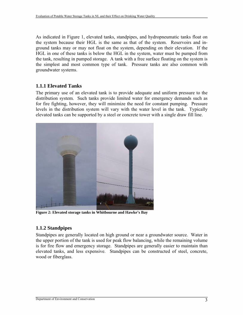
1.1.1 Elevated Tanks The primary use of an elevated tank is to provide adequate and uniform pressure to the distribution system. Such tanks provide limited water for emergency demands such as for fire fighting, however, they will minimize the need for constant pumping. Pressure levels in the distribution system will vary with the water level in the tank. Typically elevated tanks can be supported by a steel or concrete tower with a single draw fill line.
Figure 2: Elevated storage tanks in Whitbourne and Hawke’s Bay
1.1.2 Standpipes Standpipes are generally located on high ground or near a groundwater source. Water in the upper portion of the tank is used for peak flow balancing, while the remaining volume is for fire flow and emergency storage. Standpipes are generally easier to maintain than elevated tanks, and less expensive. Standpipes can be constructed of steel, concrete, wood or fiberglass.
Evaluation of Potable Water Storage Tanks in NL and their Effect on Drinking Water Quality
Department of Environment and Conservation 4
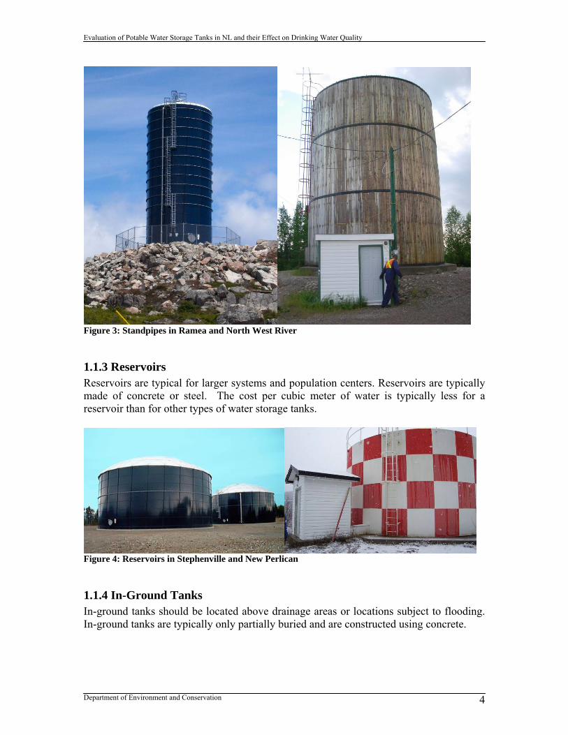
Figure 3: Standpipes in Ramea and North West River
1.1.3 Reservoirs Reservoirs are typical for larger systems and population centers. Reservoirs are typically made of concrete or steel. The cost per cubic meter of water is typically less for a reservoir than for other types of water storage tanks.
Figure 4: Reservoirs in Stephenville and New Perlican
1.1.4 In-Ground Tanks In-ground tanks should be located above drainage areas or locations subject to flooding. In-ground tanks are typically only partially buried and are constructed using concrete.

Evaluation of Potable Water Storage Tanks in NL and their Effect on Drinking Water Quality
Department of Environment and Conservation 5
Figure 5: In-ground tanks in Happy Valley-Goose Bay and Riverhead
1.2 Tank Appurtenances Tank appurtenances or accessories are vital for the function, operation and maintenance of the tank system. The majority of appurtenances for tanks are required by law (Occupational Health and Safety Act), industry standards (AWWA standards) or guidelines (Guidelines for the Design, Construction and Operation of Water and Sewerage Systems) in order to make the tank a safe and functional facility. Other accessories are optional and may be specified during the design to improve the tank’s function and appearance. Main tank appurtenances can include:
Access hatches Overflows Isolation valves Drains Vents (with screens) Inlet and outlet riser pipes Pipe connections Freeze prevention devices Silt stops Ladders, railings, catwalks, fall prevention devices Cathodic protection devices Security fencing, lighting, alarms and locks Sampling ports Tank identification plate Level control or monitoring devices SCADA or telemetry systems Mixing systems Antennas Sight glass Pressure gauge

Evaluation of Potable Water Storage Tanks in NL and their Effect on Drinking Water Quality
Department of Environment and Conservation 6
Examples of common tank appurtenances and components can be found in Appendix A. Tank appurtenances that directly affect resulting drinking water quality are discussed in further detail in the following sections.
1.2.1 Water Level Control in Tanks Water level controls are used to regulate the water level in storage tanks so the tank does not overflow or drain completely. Typically tank water level control is integrated with system pumping. At a pre-set maximum level a control will turn pumps off and the tank will stop filling. The tank will then drain to a set minimum level at which point a control will turn the pump on and the tank will start filling again. There are two major classifications of level measurement instrumentation: point level and continuous level measurement (Koeneman, 2010). Point level measurement indicates the absence or presence of the water level at a certain point in the tank. Continuous level measurement indicates the level of water in the tank over the full range of possible measurements. Level sensing technology can also be classified as contact and non-contact. Some water level controls provide water level measurement capability and some do not, such as altitude valves.
Monitoring of tank water levels does not require sophisticated monitoring systems, but operators should know what the water level is in their tank and how this varies over time. The most common devices used to monitor water level are gauge boards, radial pressure gauges and pressure transmitter readouts. Pressure transmitters are the most common type of level sensor used with SCADA systems for distribution system storage tanks (AWWA, 2010).
Figure 6: Radial pressure gauge (St. Alban’s), gauge board and SCADA readout used to monitor water level in tank
There are many different types of tank level controls including:
Altitude valves- an automatic control valve that responds to changes in pressure to open/close the valve, regulating the flow or pressure of a fluid. An altitude valve will remain open while the tank is filling and will close when the tank reaches its

Evaluation of Potable Water Storage Tanks in NL and their Effect on Drinking Water Quality
Department of Environment and Conservation 7
maximum level. Can be single acting or double acting. Double acting valves are used for single inlet/outlet tanks. They close when the water elevation in the tank reaches a set point, and open when the system pressure drops below another set point. Single-acting valves require a check valve bypass as they only have one set point.
Float switch- a low density float rises and falls according to the change in liquid level and operates switches at predetermined points in the range.
Radio frequency admittance- a change in the radio frequency admittance indicates either the presence or absence of water or how much material is in contact with the sensor. An elevation signal is generated for each depth where switches are located.
Conductivity switch- measures the drop in resistance that occurs when a conductive liquid is brought into contact with two probes and a vessel wall.
Hydrostatic types- a pressure transmitter (two-wire transmitter with a sensing diaphragm and a sealed electronic circuitry) is used to measure the pressure difference between the confined hydrostatic pressure of the liquid head above the sensor and the outside atmospheric pressure. It transmits an analog signal proportional to the liquid level above the sensor. Changes in pressure are converted into a 4-20 mA output signal relative to the head difference. Generally measured at some point along the tank’s piping or riser pipe.
Ultrasonic- a high frequency acoustic pulse is directed down from a transducer to the surface of the medium being measured and, by knowing the temperature and speed of sound in air, the time it takes for the pulse to rebound to the sensor is used to determine the level. Point level ultrasonic measurement electronically resonates a crystal at fixed frequency to generate sound waves that travel across an air gap to a second crystal. As liquid fills the gap between the two crystals, the second crystal begins to resonate with the first.
Microwave radar- uses frequency modulated continuous wave through air transmission that allows for accurate non-contact reading of reflected electromagnetic signals.
Magnetic- a float or cone is able to rise and fall along a stainless steel probe held in the tank fluid being measured. The float can interact magnetically with switches on the outside of the tank which send back information to the controller.
Torsion- a moving float spindle produces a change in torsion, measured by a torsion transducer.
Time Domain Relectometry- takes a highly focused electronic wave, guided by a metallic rod or flexible cable, to the surface of a liquid and reflects it back along the rod or cable to determine the level.
Vibration or tuning fork- the fork is piezoelectrically energized and vibrates at a frequency of approximately 1200 Hz. When the fork is covered in liquid, the frequency shifts which is detected by the internal oscillator and converted into a switching command.

Evaluation of Potable Water Storage Tanks in NL and their Effect on Drinking Water Quality
Department of Environment and Conservation 8
Bladder systems- a source of compressed air is used to push bubbles out of a conduit at the bottom of the tank. The pressure required to push the bubbles indicates water level. Bubblers provide continuous level sensing with air pressure transmitted as an analog voltage or current signal.
Figure 7: Water level control devices– float switch, altitude control valve, wet/dry capacitance sensor, pressure sensor, (top row), ultrasonic transducers, radar level sensor, magnetic float switch (bottom row) The following table summarizes strengths and weaknesses of most of the above mentioned level control and measurement devices.

Evaluation of Potable Water Storage Tanks in NL and their Effect on Drinking Water Quality
Department of Environment and Conservation 9
Table 2: Strengths and weaknesses of water level control and measurement devices Level Control Strength Weakness Altitude Valve Have a considerable
pressure drop, high rate of malfunction
Radio Frequency Admittance
Versatile, excellent spill/overflow protection, simple to install, no moving parts, robust design, good accuracy and repeatability of measurements, recalibration not required, good for short span measurements, ranges up to several hundred feet
Tuning Forks Reliable high and low flow measurements, good for a wide variety of liquids
Ultrasonic Reliable high and low flow measurements, good for a wide variety of liquids, ok for non-metallic tanks, ranges up to 40 m
Conductivity Switch Economical Not good for coating and conductive liquids
Float Switch Good for basic applications, cost effective
Require extensive maintenance, less reliable and accurate than electronic systems, not recommended in freezing climates
Hydrostatic Reliable, simple to use, able to transmit data to another receiver for remote monitoring, ok for non-metallic tanks, ranges up to several hundred feet
Are sensitive enough to sense pressure changes created by water movement that can cause false readings
Microwave Radar OK for non-metallic tanks, ranges up to 40 m
Magnetostrictive OK for non-metallic tanks, range up to 12 m
Time Domain Relectometry
OK for non-metallic tanks, good for tanks with internal obstructions, uses less energy than airborne radar technologies, ranges up to 35 m in selected applications
Evaluation of Potable Water Storage Tanks in NL and their Effect on Drinking Water Quality
Department of Environment and Conservation 10
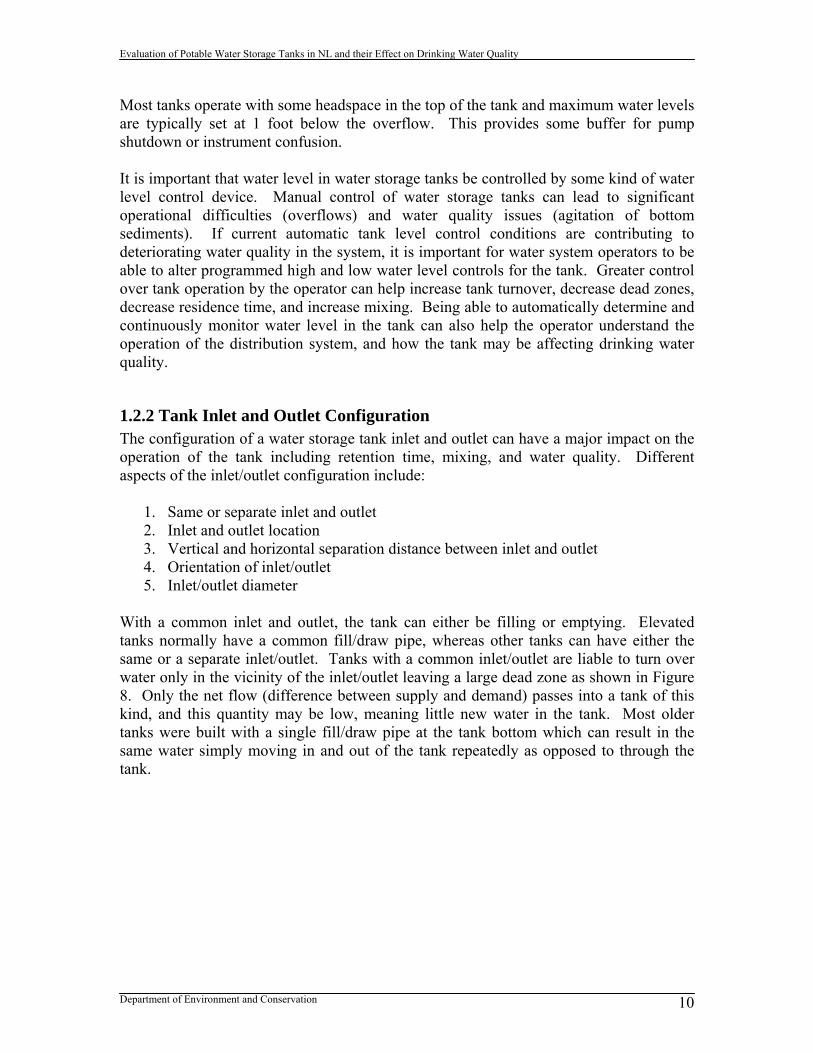
Most tanks operate with some headspace in the top of the tank and maximum water levels are typically set at 1 foot below the overflow. This provides some buffer for pump shutdown or instrument confusion. It is important that water level in water storage tanks be controlled by some kind of water level control device. Manual control of water storage tanks can lead to significant operational difficulties (overflows) and water quality issues (agitation of bottom sediments). If current automatic tank level control conditions are contributing to deteriorating water quality in the system, it is important for water system operators to be able to alter programmed high and low water level controls for the tank. Greater control over tank operation by the operator can help increase tank turnover, decrease dead zones, decrease residence time, and increase mixing. Being able to automatically determine and continuously monitor water level in the tank can also help the operator understand the operation of the distribution system, and how the tank may be affecting drinking water quality.
1.2.2 Tank Inlet and Outlet Configuration The configuration of a water storage tank inlet and outlet can have a major impact on the operation of the tank including retention time, mixing, and water quality. Different aspects of the inlet/outlet configuration include:
1. Same or separate inlet and outlet 2. Inlet and outlet location 3. Vertical and horizontal separation distance between inlet and outlet 4. Orientation of inlet/outlet 5. Inlet/outlet diameter
With a common inlet and outlet, the tank can either be filling or emptying. Elevated tanks normally have a common fill/draw pipe, whereas other tanks can have either the same or a separate inlet/outlet. Tanks with a common inlet/outlet are liable to turn over water only in the vicinity of the inlet/outlet leaving a large dead zone as shown in Figure 8. Only the net flow (difference between supply and demand) passes into a tank of this kind, and this quantity may be low, meaning little new water in the tank. Most older tanks were built with a single fill/draw pipe at the tank bottom which can result in the same water simply moving in and out of the tank repeatedly as opposed to through the tank.

Evaluation of Potable Water Storage Tanks in NL and their Effect on Drinking Water Quality
Department of Environment and Conservation 11
Figure 8: Tank with a common inlet/outlet (AWWARF, 2006) Installing the outlet separate from the inlet forces water to flow across a greater section of the tank depending on the location of the inlet and outlet. Altering the vertical level of the inlet may also increase the flow through in the tank. With circular tanks, it is more desirable to have the inlet in the center of the tank so that water flows out radially in all directions. The key of inlet and outlet placement is to ensure movement of water through the tank. Tank behaviour with a separate inlet and outlet is indicated in Figure 9.
Figure 9: Tank with a separate inlet/outlet (AWWARF, 2006) The energy of the inlet jet can be used to stir the water in the tank. The inlet orientation relative to tank geometry will determine how effective the resulting mixing will be. Tangential inlets tend to promote a flow path around the perimeter of the tank resulting in a stagnant zone in the center as indicated in Figure 10. This is most likely to occur in circular tanks, although it can happen to a lesser extent in rectangular tanks (AWWARF, 2006). Better mixing is also promoted by orienting the jet towards the maximum length of the tank.

Evaluation of Potable Water Storage Tanks in NL and their Effect on Drinking Water Quality
Department of Environment and Conservation 12
Figure 10: Tank configuration with tangential orientation of inlet (AWWARF, 2006) Reducing the diameter of the inlet pipe will increase the velocity and kinetic energy of the water entering the tank and improve mixing. In tall narrow tanks, there is a tendency for poor turnover of water at the top of the tank. Directing the inlet jet upwards and ensuring it is powerful enough to mix water throughout the tank can alleviate this problem. Alternatively, installing a high level inlet will ensure that water is forced to flow from top to bottom throughout the full depth of the tank. Water behaviour in a standpipe is illustrated in Figure 11.
Figure 11: Water behaviour in a standpipe (AWWARF, 2006) In cases where the fill/draw main leading to the tank is of considerable length, duplicating this line may be too expensive and promoting better mixing within the tank the preferred option.
1.2.3 Tank Mixing Water in storage tanks has a tendency to form undesirable stagnant or dead zones where little mixing of water occurs. The introduction of stagnant tank water into a distribution system can lead to numerous water quality problems including taste and odour complaints, loss of chlorine residual, high levels of DBPs, and introduction of microbial contamination. A tank that is well mixed achieves uniform water quality and age and is

Evaluation of Potable Water Storage Tanks in NL and their Effect on Drinking Water Quality
Department of Environment and Conservation 13
much easier to manage. An optimized mixing process may need to be determined for each tank as mixing will be dependent on tank inflow and inlet pipe diameter, the volume of water being cycled, and water temperature. Mixing in tanks can be achieved through either passive or active mixing systems. Any retrofitted or newly designed tank mixing system should be validated for that tank to demonstrate complete mixing. 1.2.3.1 Passive Tank Mixing Passive tank mixing systems do not have moving parts and do not require an outside energy source. Such systems are typically incorporated into the design of the tank, and can add considerably to the capital cost of the tank. Passive approaches may not promote the proper degree of mixing under some tank operating conditions, but are simple, reliable and require less maintenance. Methods of passive tank mixing can be classified as follows:
Inlet/outlet methods: o replacing a common inlet/outlet with separate pipes o moving the location or orientation of the inlet o increasing the distance between the inlet and outlet o reducing the diameter of the inlet o installing a duckbill or check valve to increase the velocity of the inlet jet
Flow direction methods: o installing baffles, walls or other obstructions
Operational: o force turnover of water in tank by reducing minimum operational water
level o reduce maximum water level in tank
In addition to the tank inlet/outlet configuration methods discussed in the previous section, duckbill valves can be used to increase the velocity of the inlet jet as depicted in Figure 12 to promote greater mixing in the tank. Such a system is designed to maintain movement of water in the tank even when the tank is not filling. However, if the tank does not fill for an extended period, the amount of mixing may be reduced significantly over time.

Evaluation of Potable Water Storage Tanks in NL and their Effect on Drinking Water Quality
Department of Environment and Conservation 14
Figure 12: Duckbill valve at tank inlet Fitting baffles into tanks can direct water through regions of a tank that would otherwise have poor turnover, thus eliminating short-circuiting. Optimum configurations can be difficult to determine, however. Baffles, walls and other obstructions in the path of the inlet jet tend to dissipate the strength of the inlet jet and so generally have a detrimental effect on mixing. Columns or other obstructions cause resistance to the flow of water resulting in stagnant zones. Columns in circular tanks have been observed to cause water to swirl around the perimeter of the tank (AWWARF, 2006). Baffles are also expensive, increase surface area for biogrowth and require more maintenance cleaning. Water behaviour in tanks with obstructions and baffles is indicated in Figure 13. Baffles, obstructions and walls are not recommended in finished water storage tanks.

Evaluation of Potable Water Storage Tanks in NL and their Effect on Drinking Water Quality
Department of Environment and Conservation 15
Figure 13: Tank configurations with obstructions and baffles (AWWARF, 2006) In chlorine contact chambers, baffles and walls can be used to prolong the residence time of water in the tank by promoting plug flow, thereby increasing the time the disinfectant is in contact with the water to inactivate pathogens before water goes to the first user. 1.2.3.2 Active Tank Mixing Active tank mixing systems have moving parts and require an outside energy source in order to function. They tend to be easy to specify and operate and provide a better guarantee of complete tank mixing achieving uniform water temperature, chemistry and age. Methods of active tank mixing include:
adjusting pump operation install paddle or impellor devices to improve mixing within the tank tank aeration or re-circulation
Altering pump schedules can be used as a control method to reduce residence times in storage tanks by several different methods. By adjusting the pumping regime, it is often possible to improve the balance between network demand and the supply from the pumps and thereby reduce the volume of storage required. Changing the water level in the tank at which pumps operate can increase the daily variation in water level in the tank, force turnover of water, change mixing patterns, and reduce the likelihood of stagnant water

Evaluation of Potable Water Storage Tanks in NL and their Effect on Drinking Water Quality
Department of Environment and Conservation 16
remaining in the tank. Where the flow is controlled by variable speed pumps or multi-pump installations, it may be possible to increase the pumping rate for a short period each day so as to increase the velocity at the tank inlet and improve mixing. Paddles and impellors can also be installed in tanks as a mechanical means of mixing water and preventing stagnant zones. There are a number of commercially available devices on the market, some of which are solar powered or can incorporate secondary disinfection dosing equipment. Two such in-tank mixing devices are illustrated in Figure 14.
Figure 14: Tank active mixing devices– draft tube (left), vortex mixer (right) Aeration is the process by which air is circulated through, mixed with, or dissolved in a liquid substance. Tank aeration systems can be comprised of a recirculation pump that draws water from the bottom of the tank and discharged it into the atmosphere via a spray nozzle above the water surface as shown in Figure 15 or from compressed air bubblers (Walfoot, 2008). Tank aeration promotes better mixing of water in the tank, reduces water aging, and helps volatize certain DBPs that may form in the tank.

Evaluation of Potable Water Storage Tanks in NL and their Effect on Drinking Water Quality
Department of Environment and Conservation 17
Figure 15: Spray aeration system in water storage tank (Walfoot, 2008)
1.3 Tank Operation and Maintenance Most tank manufacturers will now provide a standard operation and maintenance manual to communities upon completion of construction. Various AWWA manuals and standards also provide best management practices for system operators regarding their water storage tanks. Although full-service asset management programs are not common in the province, in other jurisdictions it is not unheard of for a municipality to hire a secondary utility service company to look after their water storage tanks. To a limited extent this is done in the province when a town wants to get their tank inspected or refurbished. The following local companies have been involved with providing such services to communities over the past number of years:
Eastern Technical Services Ltd. (inspections) Atlantic Sandblasting and Painting (refurbishment)
1.3.1 Tank Operation The operation of water storage tanks tends to happen in a bit of a black box for many communities. The tank sits on the system, fills and empties, and little attention is paid to how the tank is actually operating. In the past decade, however, there has been a greater awareness of how water storage tank operation affects not only distribution system hydraulics, but also the water quality. Various operational strategies have also been devised to deal with some of the issues identified.
Evaluation of Potable Water Storage Tanks in NL and their Effect on Drinking Water Quality
Department of Environment and Conservation 18
Operation of water storage tanks involves consideration of the following main areas discussed in this and other sections of this report:
1. Turnover rates in water tanks 2. Tank mixing 3. Maintaining optimal water quality in tanks 4. Tank security and access
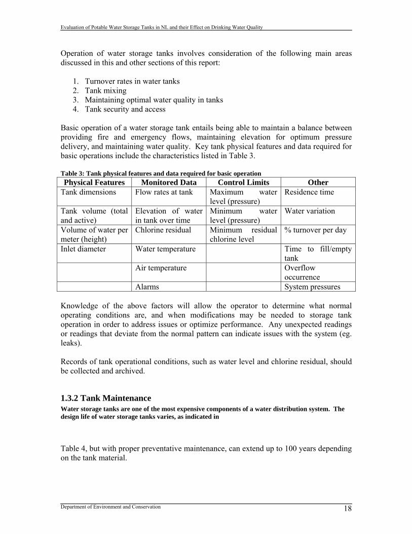
Basic operation of a water storage tank entails being able to maintain a balance between providing fire and emergency flows, maintaining elevation for optimum pressure delivery, and maintaining water quality. Key tank physical features and data required for basic operations include the characteristics listed in Table 3. Table 3: Tank physical features and data required for basic operation Physical Features Monitored Data Control Limits Other
Tank dimensions Flow rates at tank Maximum water level (pressure)
Residence time
Tank volume (total and active)
Elevation of water in tank over time
Minimum water level (pressure)
Water variation
Volume of water per meter (height)
Chlorine residual Minimum residual chlorine level
% turnover per day
Inlet diameter Water temperature Time to fill/empty tank
Air temperature Overflow occurrence
Alarms System pressures Knowledge of the above factors will allow the operator to determine what normal operating conditions are, and when modifications may be needed to storage tank operation in order to address issues or optimize performance. Any unexpected readings or readings that deviate from the normal pattern can indicate issues with the system (eg. leaks). Records of tank operational conditions, such as water level and chlorine residual, should be collected and archived.
1.3.2 Tank Maintenance Water storage tanks are one of the most expensive components of a water distribution system. The design life of water storage tanks varies, as indicated in Table 4, but with proper preventative maintenance, can extend up to 100 years depending on the tank material.

Evaluation of Potable Water Storage Tanks in NL and their Effect on Drinking Water Quality
Department of Environment and Conservation 19
Table 4: Design life of water storage tanks
Drinking Water Component Years Water Storage Tank
Concrete Wood Metal Fiberglass
25-100 50-80 25-50 50-100 50-80
Maintenance of tanks requires routine assessment of the tank condition. Condition assessments can be either routine inspections (weekly), periodic inspections (annual), or comprehensive inspections (every 3-5 years). Depending on the type of inspection, various levels of condition assessment should be undertaken including an assessment of:
1. Sanitary conditions Inspect openings that can allow fauna (birds, squirals, insects, etc.)
into the tank– roof openings, access hatches, low spots on roof plates, vents, overflows, penetrations
2. Structural conditions Inspect anchor bolts, foundations and grouting, wind rods, metal loss
in steel plates, spider rods, roof trusses 3. Safety conditions
Inspect ladders (inside and outside), fall prevention devices, handrails, access hatches
Tanks are deemed confined spaces under Occupational Health and Safety rules
4. Coatings conditions Evaluate general condition, approximated percentage and type of
failure, thickness, adhesion, extent of pitting damage, heavy metal presence, bubbling, alligatoring, ice scraping
5. Security conditions Inspect fences, locks, barricades, lighting, ladder guards, alarm
systems, water monitors (residual chlorine analyzer), control systems Inspecting tanks regularly is a good practice to extend the useful life of the tank, save money on tank rehabilitation, to determine long and short term maintenance planning and budgeting, and to achieve compliance with regulatory agency requirements. A tank should be drained and cleaned every 3-5 years depending on the rate of sediment deposition in the tank. A tank inspection should consist of careful examination of the tank’s interior, exterior, foundation and accessories. Potable water storage tanks require routine inspections at the following frequencies (AWWARF, 1999):
Evaluation of Potable Water Storage Tanks in NL and their Effect on Drinking Water Quality
Department of Environment and Conservation 20
Routine inspections: daily or weekly Periodic inspections: quarterly or annual Comprehensive inspection: every 3 to 5 years
The community should have a written inspection program outlining frequency, procedures and maintenance of records. The inspection program should include such features as routine, periodic and comprehensive inspections.
1.4 Tanks and Water Quality Issues The goal of operating water storage tanks is to deliver the highest quality of water available to users. Water quality issues associated with tanks can include:
Microbiological issues – pathogenic contamination, bio-films Chemical issues – leaching of chemicals from tank linings or coatings, loss of
chlorine residual, DBP growth, precipitates Physical issues – water temperature, turbidity from sediment build-up
Factors that can contribute to water quality problems in water storage tanks include improper tank design, aging of water, inadequate maintenance, intrusion of fauna, improperly applied or cured coatings and linings, and lack of mixing. Lack of water turnover in storage facilities has long been recognized as a primary cause of water quality problems within a distribution system. Disinfectants have more time to react with compounds in the bulk water in storage tanks with large dead zones, low water turnover rates or poor circulation. The location of the tank on the distribution system can also affect chlorine residuals, water age and DBP levels. The majority of tanks in the province are located at the beginning of the distribution system, after the chlorinator and before the first user. Tanks located at the end of the distribution system tend to increase water age in the tank and the distribution network, and increase the variability of chlorine residuals throughout the system.
1.4.1 Water Age If water stagnates or does not cycle or turnover in a storage tank, it will age indefinitely until it happens to mix with active water or get drawn from the tank into the distribution system. Such stagnant water will not be of the highest quality and may result in low chlorine residuals, pathogen contamination, high DBPs and taste and odour complaints. It is important to keep water age in the tank as low as possible in order to keep water quality at its peak. Different jurisdictions have regulatory requirements for maximum tank water retention time ranging from 1-5 days or a set required percentage turnover per day. Excessive water age in tanks is exacerbated by the need for emergency and fire storage that essentially act as inactive storage in the tank. Tanks can also be over-designed if
Evaluation of Potable Water Storage Tanks in NL and their Effect on Drinking Water Quality
Department of Environment and Conservation 21
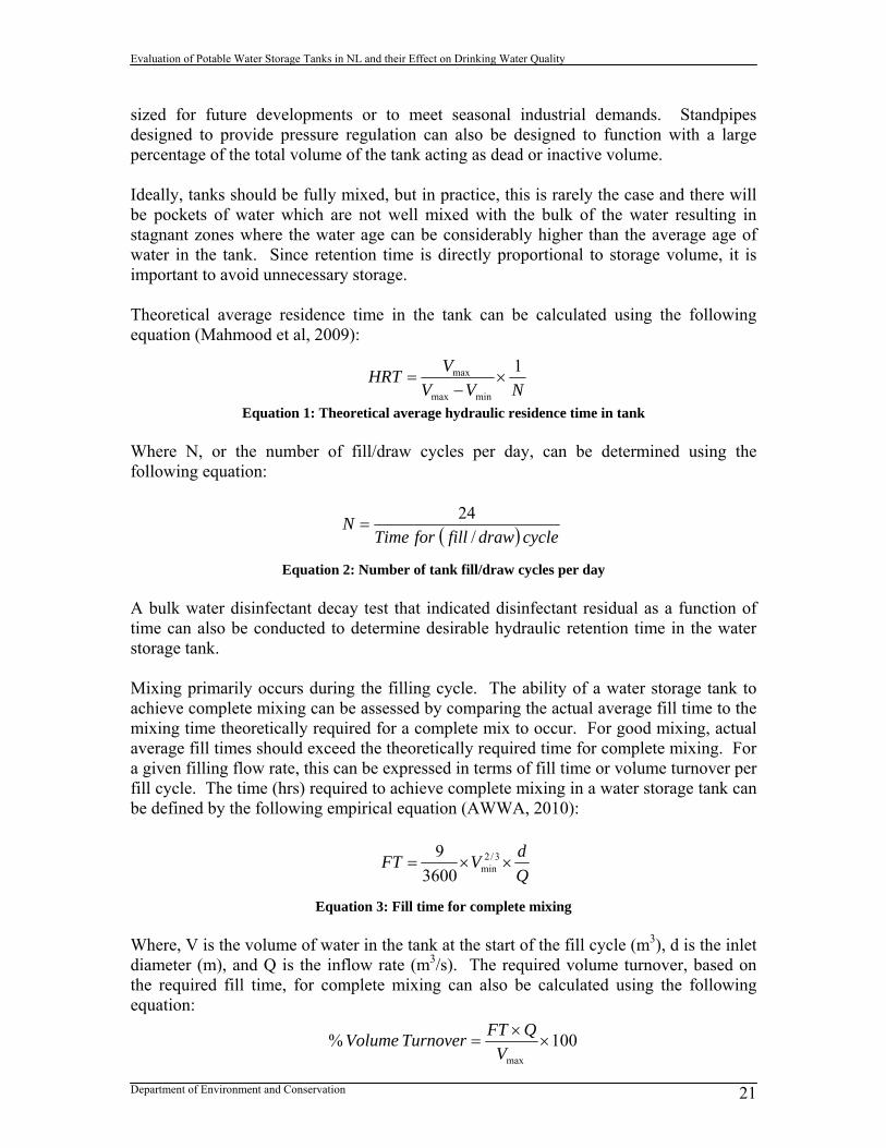
sized for future developments or to meet seasonal industrial demands. Standpipes designed to provide pressure regulation can also be designed to function with a large percentage of the total volume of the tank acting as dead or inactive volume. Ideally, tanks should be fully mixed, but in practice, this is rarely the case and there will be pockets of water which are not well mixed with the bulk of the water resulting in stagnant zones where the water age can be considerably higher than the average age of water in the tank. Since retention time is directly proportional to storage volume, it is important to avoid unnecessary storage. Theoretical average residence time in the tank can be calculated using the following equation (Mahmood et al, 2009):
Equation 1: Theoretical average hydraulic residence time in tank Where N, or the number of fill/draw cycles per day, can be determined using the following equation:
Equation 2: Number of tank fill/draw cycles per day A bulk water disinfectant decay test that indicated disinfectant residual as a function of time can also be conducted to determine desirable hydraulic retention time in the water storage tank. Mixing primarily occurs during the filling cycle. The ability of a water storage tank to achieve complete mixing can be assessed by comparing the actual average fill time to the mixing time theoretically required for a complete mix to occur. For good mixing, actual average fill times should exceed the theoretically required time for complete mixing. For a given filling flow rate, this can be expressed in terms of fill time or volume turnover per fill cycle. The time (hrs) required to achieve complete mixing in a water storage tank can be defined by the following empirical equation (AWWA, 2010):
Equation 3: Fill time for complete mixing Where, V is the volume of water in the tank at the start of the fill cycle (m3), d is the inlet diameter (m), and Q is the inflow rate (m3/s). The required volume turnover, based on the required fill time, for complete mixing can also be calculated using the following equation:
NVV
VHRT
1
minmax
max
cycledrawfillforTimeN
/
24
Q
dVFT 3/2
min3600
9
100%max
V
QFTTurnoverVolume

Evaluation of Potable Water Storage Tanks in NL and their Effect on Drinking Water Quality
Department of Environment and Conservation 22
Equation 4: Required volume turnover for complete mixing
1.4.2 Chlorine Disinfectant Residual The loss of chlorine residual in the water storage tank is one of the greatest operational difficulties faced by communities with water storage tanks. Typically, disinfectant residuals enter the tank at acceptable levels, but exit the tank at low or unpredictable levels. The problem can be exacerbated by the location of the tank in the distribution system. Water will age in a storage tank depending on the mixing conditions. Where there is good mixing, the retention time will cycle over a fixed period. However, where stagnant zones form, water age can increase indefinitely. Complete loss of chlorine residual in a storage tank can lead to the formation of bio-films along surfaces in the tank. Bio-films can then act as a location for bacteriological growth and pathogenic contamination. Chlorine dosage at the point of application can range from 3-12 mg/L. Being able to maintain a threshold chlorine residual of 1.0 mg/L in the tank is advisable. Monitoring of chlorine residual levels in a tank can be achieved on a continuous basis with chlorine residual analyzers or by the collection of grab samples from at least the top and bottom of the tank on a weekly basis. A uniform chlorine residual profile in a tank is a sign of a well mixed tank. Chlorine follows an exponential decay pattern over time once it has been dosed into the drinking water system, meaning decay occurs rapidly early on and is more prolonged thereafter as indicated in Figure 16. The longer water is retained in the storage tank, the more chlorine will decay.
Bulk Chlorine Decay
01
23
45
67
0.00 50.00 100.00 150.00
Time (h)
Fre
e C
hlo
rin
e (m
g/L
)
Free Cl (mg/L) Expon. (Free Cl (mg/L))
Figure 16: Bulk water chlorine decay observed in the town of Brighton

Evaluation of Potable Water Storage Tanks in NL and their Effect on Drinking Water Quality
Department of Environment and Conservation 23
Loss of chlorine disinfectant residual in the tank can be counteracted by increased mixing to reduce water age and homogenize the distribution of disinfectant residual within the tank. Secondary disinfection dosing equipment or a chlorine booster can also be added to the tank or to the outlet of the tank in order to better manage residual levels.
1.4.3 Disinfection By-Products Disinfection by-products are formed when a disinfectant such as chlorine is added to water in order to inactivate pathogenic organisms, and reacts with other substances in the water such as naturally occurring organic matter. Trihalomethanes (THMs) and haloacetic acids (HAAs) are the two most significant, regulated DBPs of concern for most jurisdictions. DBPs tend to follow a saturation growth pattern, where formation occurs very rapidly initially, and then slows to a maximum saturation point over time. The saturation point is dependant on the amount of disinfectant dosed into the system. Decay may even occur at a certain point, particularly for HAAs. Figure 17 provides an example of THM growth in a distribution system.
Figure 17: Simulated DBP Formation for Exploits Regional Water System (CH2MHill, 2010) As chlorine residual decays with time in the tank, that chlorine is in part being used to form DBPs. The longer the residence time of chlorinated water in the tank, the higher the

Evaluation of Potable Water Storage Tanks in NL and their Effect on Drinking Water Quality
Department of Environment and Conservation 24
level of DBPs that will be formed. Distribution systems with tanks have been found to have significantly higher DBP levels than systems without due to the additional residence time in the distribution system.
1.4.4 Water Temperature Many tanks suffer from thermal loading where there is a large variation in water temperature from the top to bottom of the tank. A uniform water temperature profile in a tank is a sign of a well mixed tank. The temperature of water also affects the rate of chemical reactions that occur in the bulk water of the tank. A common approximation is that the reaction rate doubles for every 10°C rise in temperature, otherwise known as the van Hoff approximation. In particular this affects the rate of chlorine residual decay and DBP formation. Warmer water temperatures can make it harder to maintain chlorine residuals in the tank, increase the rate of DBP formation, promote the growth of bio-films, and increase the risk of pathogenic contamination. The density of water is also affected by water temperature and can lead to stratification in the tank. Cold water is denser than warm water and will sink to the bottom of the tank (water reaches peak density at 4°C). If the water flowing into a tank is significantly colder than the general water temperature in the tank, the cold inflowing water will sink to the base of the tank with the warmer, older water floating on top. Relatively little mixing will occur between the warm (old) water and the cold (fresh) water. Alternatively, stratification can also occur when the inflow is significantly warmer than the general water temperature in the tank. In this case the warmer fresh water will float to the top of the tank leaving a body of cold and older water at the bottom of the tank. This is most likely to occur in winter with above ground steel tanks (AWWARF, 2006). Water behaviour in tanks due to temperature stratification is illustrated in Figure 18.

Evaluation of Potable Water Storage Tanks in NL and their Effect on Drinking Water Quality
Department of Environment and Conservation 25
Figure 18: Stratification of different temperature water in tanks (AWWARF, 2006) 1.4.4.1 Ice Formation The formation of ice in a tank is a major operational issue of concern in tanks subject to extreme winter conditions and where there is little fluctuation in water level in the tank. Ice can form in the riser pipes to the tank which can impede the flow of water into and out of the tank. It can form as a ring around the interior of the tank that can fall and cause damage to the interior coating of the tank, overflow pipe, ladder, and control devices. Ice can also form a cap across the top of the water surface in the tank that creates a vacuum when water is drawn from the tank that will cause the tank wall to buckle. Ice can also build up at the overflow. Figure 19 shows an example of ice buildup in a water storage tank and consequent damage. Active tank mixing, forcing turnover of water in the tank and adding insulation to the exterior of the tank can all help alleviate the issue of tank ice formation.

Evaluation of Potable Water Storage Tanks in NL and their Effect on Drinking Water Quality
Department of Environment and Conservation 26
Figure 19: Examples of ice damage in a water storage tank 1.4.4.2 Seasonal Temperature Inversions During the spring and fall in Northern climates, there is a period where the temperature of water coming into the tank may vary significantly from that in the tank. This creates a temperature differential that can lead to an inversion of water in the tank. Denser water will always sink to the bottom of the tank, and during an inversion, there is a sudden flip in the water from the bottom to top of the tank. Anecdotally, this sudden turnover of water in the tank has also been associated with short periods (1 or 2 days) of increased turbidity in the distribution system due to agitation of sediments in the bottom of the tank. Stratification is a particular problem with tall, narrow tanks built above ground.
2.0 Regulatory Requirements for Tanks in NL In order for a community to install a water storage tank on their distribution system, several regulatory requirements have to be met. A professional engineer must be hired to design and oversee the construction of the tank. The design must meet the requirements of ENVC’s Guidelines for the Design, Construction and Operation of Water and Sewerage Systems in order for a Permit to Construct under Section 37 of the Water Resources Act to be issued. Construction of the tank must follow the requirements of the Department of Municipal Affairs (DMA) specifications as set out either in the Tender or Request for Proposals (RFP). If the tank is to be constructed through the tender process, the lowest bidder that meets required specifications wins the bid and constructs the tank. If the tank installation goes through the RFP process, all tank proposals that meet specifications are evaluated and ranked with the top ranked proposal selected for tank construction.

Evaluation of Potable Water Storage Tanks in NL and their Effect on Drinking Water Quality
Department of Environment and Conservation 27
Once the tank is built, its operation is governed by the Permit to Operate for a water distribution system issued by ENVC under Section 38 of the Water Resources Act. The province does not require that water system operators of systems with water storage tanks be certified. Operators of systems with water treatment plants, however, must be certified. The province is also moving towards mandatory certification of water system operators on systems serving a population greater than 1000. Operator education, training and certification offered by ENVC are available to all operators in the province.
2.1 Design Guidelines Section 3.6 of the Newfoundland and Labrador Guidelines for the Design, Construction and Operation of Water and Sewerage Systems (2005), hereafter referred to as the Design Guidelines, deals with finished water storage tanks. The Design Guidelines are meant to provide general guidance on good engineering practice for design, construction, operation and maintenance aspects of water systems. Specific design requirements for tanks are outlined in Table 5. Table 5: Design requirements for tanks Section Design Requirement 3.6.3.1 All water storage facilities and associated appurtenances must meet CSA,
ANSI, AWWA or NSF 61 standards. 3.6.4 Hydraulic analysis should be undertaken to determine the location,
capacity and maximum water level of water storage tanks to assure acceptable service pressures throughout existing and future service areas.
3.6.4.1-9 Criteria to be considered when designing water storage tanks include demand equalization, system operation, smoothing pumping requirements, reducing power costs, emergency storage, fire storage, pressure surge relief, detention time, and blending of water sources.
3.6.5 Water storage tanks can provide for domestic demand, fire flow, and emergency storage. Water storage requirements can be calculated using:
CBAS Equation 5: Water storage requirement
where: S = total storage requirement, m3 A = Fire storage, m3, typically established by the appropriate Insurance Advisory Organisation (IAO) B = Peak balanced storage, m3, 25% of maximum day demand C = Emergency storage, m3, 25 % of A + B or 15 % average daily design flow or 40 % of average daily design flow when no fire storage
3.6.5.4 When dead storage is present there must be adequate measures taken to circulate the water through the tank to maintain quality.
3.6.6.2 The bottom of above ground reservoirs and standpipes should be placed at the normal ground surface and should be above maximum flood level based on a 100-yr flood.

Evaluation of Potable Water Storage Tanks in NL and their Effect on Drinking Water Quality
Department of Environment and Conservation 28
The bottom of in-ground tanks must be located above the groundwater table.
Sewers, drains, standing water, or other sources of possible contamination must be kept at least 15 m from the reservoir.
The top of an in-ground tank must not be less than 600 mm above normal ground surface.
3.6.7.1-17 Tanks require detailed design of inlet/outlet, level controls, overflow, drainage (tank and roof), roof, vents, frost protection, silt stop, grading, internal and external coatings, riser, and piping.
3.6.10.1-3 Tanks require detailed design security features including access hatches, locks, ladders, balconies, railings, fences, and screens.
Specific operational requirements for tanks are outlined in Table 6. Table 6: Operational requirements for tanks Section Operational Requirement 3.6.5.5 The maximum allowable detention time in the water storage tank is 72-hours.3.6.7.2 Changes in water level in a storage tank during daily domestic water
demand should be limited to a maximum 9 m to stabilize pressure fluctuations within the distribution system.
Pumps should be controlled from tank levels. Tank overflows should be avoided. Overflow and low-level warnings or alarms should be located where
they can be monitored 24 hours a day. 3.6.10.1 Only trained and experienced workers should be allowed to work around
water storage facilities. The Design Guidelines were last updated in 2005 and are based upon the Atlantic Canada Guidelines for the Supply, Treatment, Storage, Distribution and Operation of Drinking Water Supply Systems and the 10 State Standards. Since this time other provinces, including Ontario and Alberta, have updated their design guidelines.
2.2 Permits to Construct Permits to Construct, or prior to the mid 90’s, Environmental Approvals have been issued by ENVC since the mid 70’s in an effort to ensure the safe and appropriate design of drinking water infrastructure throughout the province. At least 79 Permits to Construct relating to water storage tank construction, refurbishment or rehabilitation have been issued over the period from 1994 to 2010. Work on a water storage tank cannot proceed without first having a permit issued. The terms and conditions in a permit relating to a tank will include general construction best management practices, requirements for meeting AWWA and NSF standards, requirements for meeting Design Guidelines and specifications, requirements for hydrostatic testing and disinfection of the water storage tank prior to it coming online. A

Evaluation of Potable Water Storage Tanks in NL and their Effect on Drinking Water Quality
Department of Environment and Conservation 29
violation of any of the terms and conditions in the Permit to Construct is considered a violation of the Water Resources Act.
2.3 Technical Specifications The difference between design guidelines and technical specifications is in the level of detail. Design guidelines are criteria that must be followed in designing something, focusing on the inputs, outputs and functional requirements of what is to be designed. A specification is a document that is used after the design is complete that details the type of equipment, material, dimensions, components, etc. that will be used to build what was designed. The technical specification also has contractual and legal implications. DMA is responsible for technical specifications used in the construction of drinking water infrastructure. This includes the Water, Sewer and Roads Master Specification, with any required supplementary information or specifications provided by consultants. The current provincial Master Specification document has no section on water storage tanks. In the past, specifications for tanks have been developed by the consultant as part of the tender. Issues have arisen with consultants using the technical specification of specific tank manufacturers, effectively preventing other manufacturers from being able to meet the specification, and creating a sole-source scenario for the supply of the water storage tank in question. In such cases, the technical specification used by the consultant exceeded AWWA Standards. A tank manufacturer who meets the AWWA Standards, but who does not meet the technical specification of a rival manufacturer would therefore be excluded from the tender. DMA is currently working on developing a Terms of Reference for the design, supply and erection of water storage tanks. Through the Request for Proposal process a proponent will be selected on the basis of the highest overall score achieved on various criteria including life cycle costing. For larger scale projects such as water treatment plants and wastewater treatment plants where there are a variety of processes and equipment that can potentially meet requirements, DMA is working on a Policies and Procedures Manual. The manual would outline for each type of project what procedures or template must be followed. Such a manual would be helpful for larger scale projects issued under RFPs. Currently, tank projects must go through the RFP process, however, this may be excessive given the limited number of tank options (material) available. DMA plans to incorporate the Terms of Referenced developed for tank RFPs into the Policies and Procedures Manual. It is recommended that DMA develop a generic tank specification that encompasses steel bolted, steel welded and concrete tanks (either collectively or separately) and that meets minimum requirements of the ENVC Design Guidelines and AWWA Standards. This tank specification should be added to the Master Spec, the DMA Policies and Procedures Manual that is in development, or some other format by which it can be made available to interested parties (web site). This generic tank specification can then be used by consultants, and in the tender or RFP process, without unfairly excluding tank manufacturers that meet these minimum requirements.

Evaluation of Potable Water Storage Tanks in NL and their Effect on Drinking Water Quality
Department of Environment and Conservation 30
2.4 Permits to Operate ENVC issues Permits to Operate for water distribution systems and for water treatment plants. The permits issued for water distribution include the operation and maintenance of water storage tanks or reservoirs. If a town has one or more water storage tanks, each tank is individually identified in the permit. The type, general location and volume of the tank are explicitly outlined in the permit. Permits to operate are meant to provide a stronger regulatory framework for the operation and maintenance of water infrastructure and to encourage a minimum level of best practice among system owners and operators. Permits to Operate for water distribution system are valid in perpetuity unless there has been a major change to the distribution system, such as the addition of a finished water storage tank. There are, however, no explicit terms and conditions in the Permit to Operate related to the operation and maintenance of water storage tanks. Permits to Operate for water distribution systems have been issued to almost every town with a public drinking water system in the province. The following summarized terms and conditions in the permit may relate to the operation of water storage tanks:
the owner must properly operate and maintain the water distribution system the system should be operated to provide safe and clean drinking water to
consumers the owner must establish a maintenance and operation program that includes
regular maintenance activities as per manufacturer=s recommendations and as required by ENVC
a maintenance schedule must be maintained for task specific items to be completed on a daily, weekly, monthly, and annual basis
all water distribution system operators must have a thorough understanding of all aspects of the water supply and distribution system
where corrosion is identified, corrective measures must be undertaken Due to a lack of resources, there has been relatively little follow-up on determining regulatory compliance with Permits to Operate. Any regulatory compliance or inspection effort for Permits to Operate in the future must include review of water storage tanks and their operation.
2.5 Operator Education, Training and Certification The Operator Education, Training and Certification (OETC) Program provides free training to water system operators in order to improve their knowledge and skills. The education component of the program involves classroom lessons, while the training component provides operators with hands on experience out in the field. The topic of water storage tanks is touched on in one of the three core educational seminars offered by the OETC Program for Water Distribution Levels I & II – Water Quality Issues: Water Quality in the Distribution System. There is no specific training

Evaluation of Potable Water Storage Tanks in NL and their Effect on Drinking Water Quality
Department of Environment and Conservation 31
seminar on water storage tanks. The section on water storage covers briefly the following topics:
Reasons for water storage Types of storage facilities Tank level controls Water quality issues Tank maintenance
To date there has been no hands on training related specifically to tanks. Such training would have to focus on tank inspections, condition assessments and operational monitoring of tanks. Certification is currently not required for distribution systems with water storage tanks, however, the province is moving toward mandatory certification for communities servicing more than 1000 people.
3.0 Finished Water Storage Tanks in Newfoundland and Labrador There are currently 124 finished water storage tanks in 88 different communities (and regional water systems) across the province. Information collected on each individual water storage tank can be found in the Water Storage Tank Database found in Appendix B. The majority of existing tanks or 45% can be classified as standpipes as indicated in Figure 20. Elevated storage tanks are the least common in the province. The trend in the type of tank installed in the province has changed over the years with increasing numbers of standpipes. Elevated tanks were more commonly selected in the 70s and early 80s (Hawke’s Bay). Reservoirs tend to be the preferred option for larger systems (St. John’s, Mount Pearl, Gander, Stephenville), and in-ground tanks are commonly associated with water treatment plants (St. John’s, Pasadena, Grand Falls-Windsor).

Evaluation of Potable Water Storage Tanks in NL and their Effect on Drinking Water Quality
Department of Environment and Conservation 32
Finished Water Storage Tank Type
26%
45%
27%
2%
In Ground
Standpipe
Reservoir
Elevated
Figure 20: Water storage tank classification in Newfoundland and Labrador The majority or 83% of finished water storage tanks are located on systems with a surface water source as indicated in Figure 21. Groundwater systems account for only 17% of storage tanks. The average population of a community with a storage tank is 4265, which indicates that storage tanks are more commonly associated with larger systems, but not exclusively.
Finished Water Storage Tanks by Source Type
83%
17%
Surface Water
Groundwater
Figure 21: Water storage tanks by source type

Evaluation of Potable Water Storage Tanks in NL and their Effect on Drinking Water Quality
Department of Environment and Conservation 33
The location of water storage tanks is fairly evenly distributed across the Eastern, Central, Western and Labrador regions of the province as indicated in Figure 22. The largest proportion of tanks is in the Eastern region with the high concentration of tanks around the greater St. John’s area.
Finished Water Storage Tanks by Region
27%
39%
25%
9%
Central
Eastern
Western
Labrador
Figure 22: Water storage tanks by region The majority of tanks in the province are located either somewhere in the middle of the distribution system or at the very beginning of the system. Only 6% of tanks are located at the very end of the distribution system. The location of the tank can have a significant effect on the operation of the water distribution system and resultant water quality.

Evaluation of Potable Water Storage Tanks in NL and their Effect on Drinking Water Quality
Department of Environment and Conservation 34
Tank Location on Distribution System
46%
48%
6%
Beginning
Middle
End
Figure 23: Tank location on the distribution system The material the tank is constructed of can have a significant effect on the lifespan of the tank and the level of maintenance work required. The majority of tanks in the province are either made of welded steel, bolted steel or concrete, as indicated in Figure 24. One tank in the province is constructed of wood. The material used in the construction of the tank has a major impact on the cost of the tank.
Tank Material
1%
31%
41%
26%
1%
Wood
Concrete
Steel- welded
Steel- bolted
Steel- welded/ concrete
Figure 24: Tank material

Evaluation of Potable Water Storage Tanks in NL and their Effect on Drinking Water Quality
Department of Environment and Conservation 35
3.1 Tank Cost Tank costs vary with type, capacity and location (AWWA, 1998). Generally speaking, a steel reservoir of a certain volume will cost less than either a steel standpipe or elevated tank of the same volume. Based on known tank construction costs for 19 tanks in the province since 1999, the following analysis was performed. The type of tank– reservoir, standpipe, elevated or in-ground– and its material is a prime influence on the cost. Based on available data, the cost per unit volume of a standpipe is significantly greater than that of a reservoir. Less material is needed to contain a given capacity of water in tanks that have a diameter equal to their height. Construction costs are typically higher the more lifting that is involved and the higher the assembly operation (AWWA, 1998). Steel bolted tanks also cost considerably more than concrete tanks per unit volume.
Average Tank Cost per Cubic Meter vs. Tank Type
0
100
200
300
400
500
600
700
800
900
Reservoir Standpipe
Tank Type
Ave
rag
e T
ank
Co
st p
er m
3
Figure 25: Average tank cost per m3 vs. tank type

Evaluation of Potable Water Storage Tanks in NL and their Effect on Drinking Water Quality
Department of Environment and Conservation 36
Average Tank Cost per Cubic Meter vs. Tank Material
0
100
200
300
400
500
600
700
Concrete Steel Bolted
Tank Material
Ave
rag
e T
ank
Co
st p
er m
3
Figure 26: Average tank cost per m3 vs. tank material As can be seen in Figure 27, the cost per cubic meter of storage volume decreases exponentially with increasing tank capacity. This also relates to tank type and material as all large capacity tanks (greater than 1900 m3) in the province are typically reservoirs and typically made of concrete. At smaller volumes, concrete reservoirs are significantly less competitive with steel standpipes and reservoirs.
Figure 27: Tank cost per m3 vs. tank capacity
Tank Cost per Cubic Meter vs. Tank Capacity
0
200
400
600
800
1000
1200
1400
1600
1800
0 2000 4000 6000 8000 10000 12000 14000 16000 18000
Capacity (m3)
Tan
k C
ost
per
m3
Large tanks (typically reservoirs)

Evaluation of Potable Water Storage Tanks in NL and their Effect on Drinking Water Quality
Department of Environment and Conservation 37
The location of the storage tank also appears to have some influence on the cost per unit volume, given the limited data available. The cost of tanks per unit volume is less in the Eastern region than in the Western region. This is due to the higher population centres in the Eastern region necessitating larger tanks with a lower cost per unit volume. As well, the unit volume cost of tanks in Labrador is high, reflecting the cost of construction in northern and remote regions and additional insulation and heat tracing requirements to prevent freezing.
3.2 Design Issues with Tanks in NL There has been an evolution in water storage tank design over the years. Originally, most towns in the province put in tanks in order to meet the requirements for fire flow, flushing flows or fish plant demand. More recently tanks have been put in to provide for storage and adequate pressure. Too frequently, the wrong type of water storage tank has been constructed in a community for the wrong reason. For example, putting in a standpipe to provide system pressure when an elevated storage tank would have been more suitable, or putting in a tank to provide pressure which could have been achieved by a different pumping arrangement. Both ENVC and DMA have been pushing for better design of water storage tanks in recent years, including improved tank mixing. However, it has been difficult to overcome the attitude that additional elements to tank design are needless and expensive extras. A town requesting to install a tank on their water distribution system will apply for capital works funding from the DMA. Typically the town will hire a consultant to submit the application on their behalf. Once funding for the project has been approved, installation of the water storage tank will either go through the tender or request for proposals (RFP) process at the discretion of DMA. Since 2010, DMA has been using the RFP process for water storage tanks. Under the tender process, after funding has been approved, an engineering consultant will be hired to design the tank. The consultant will design the tank based on the hydraulic requirements of the system, American Water Works Association (AWWA) standards, and the ENVC Design Guidelines. On behalf of the town, the consultant will submit the design to ENVC for review and approval. Once a Permit to Construct has been issued by ENVC, DMA will tender the project in the name of the town for contractors to bid on. The contractor will contact equipment suppliers and develop a bid. At this stage, the contractor/supplier may have a choice on different aspects of the tank (type of material, mixing device, number of tanks) and may suggest a design solution that differs from the consultant’s design specifications. The consultant, acting as the town’s representative, will review the bids, estimates and shop drawings supplied by the contractor/supplier to determine which meet the design specifications. The consultant will then make a recommendation to DMA on which contractor should be awarded the tender (generally

Evaluation of Potable Water Storage Tanks in NL and their Effect on Drinking Water Quality
Department of Environment and Conservation 38
the lowest cost bid). The contractor will then move forward with construction of the tank under the direction of the consultant. Under the RFP process, after funding has been approved, DMA must prepare a Cabinet Submission to get approval for the RFP. Once approved by Cabinet, the RFP is issued. Before the RFP is issued, an engineering consultant will be hired to procure the tank through the RFP process, undertake design work and develop specifications for the tank. The RFP will include requirements for submissions including meeting ENVC Design Guidelines, AWWA Standards and the tank specification. Contractors, in collaboration with different tank suppliers, will make submissions for the RFP. These submissions will be ranked against a list of defined criteria by a Working Committee comprised of members from the consultant, town, DMA, and guidance from ENVC. Under the RFP ranking process, the lowest cost is not automatically the winning bidder as with the tender process. The Minister for DMA will send a letter to the town with a recommendation to award the contract to the highest ranked submission. The town will inform their consultant of the winning bid, who will in turn contact the successful bidder. The consultant will review the shop drawings supplied by the contractor/supplier to determine adherence to the design specifications for the selected tank. A design submission must be made by the consultant to ENVC, and after a Permit to Construct has been issued, construction on the tank may begin. The issue with the tank specification is not necessarily addressed by having the tank go through the RFP process as the consultant is still developing the specification. The requirement of getting Cabinet approval and submission review is also likely to delay projects by months. Maintaining the tender process for tanks with a DMA generic tank specification may be the best option for addressing noted issues. However, DMA is currently proceeding with the RFP process for all new storage tanks. DMA’s major concern is that tanks are being sole sourced and considers the RFP process the most effective for opening up the storage tank market in the province. The tank design submitted by the consultant usually includes the basic information highlighted in Table 7. Important elements in tank design that are often overlooked are also highlighted in this table. Such information would be useful in the evaluation of the design and operation of the water storage tank.

Evaluation of Potable Water Storage Tanks in NL and their Effect on Drinking Water Quality
Department of Environment and Conservation 39
Table 7: Elements of tank design Elements of Tank Design Typically Addressed
Elements of Tank Design Frequently Not Addressed
Tank type Tank location coordinates Tank elevation Tank site soil survey Dimensions Groundwater level Flow rate into tank Volume Maximum water level Inlet and outlet configuration Minimum water level Inlet and outlet diameter Inactive tank volume Inlet orientation Dead tank volume Path of inflow jet Active tank volume Tank level control device Number of fill/draw cycles per day Residual analyser/chlorine injection Residence time Mixing device Inlet velocity Tank insulation Inlet momentum Riser height Level of induction pump Overflow Percent turnover of water per day Vents Validation of mixing device achieving
complete mixing Drain line Fire storage, emergency storage and peak
balance storage Isolation valves Service pressure in distribution system Access hatches Drain sump in tank Ladder, railing, fence, fall arrest system Vent and overflow screen location Grading around tank Silt stop Pipe material underneath tank Greater consideration of site conditions and community need for water storage would result in improved design of water storage tanks, as opposed to generic, cookie-cutter tank installations. Greater adherence to Design Guidelines, including recommended options and not just required options, would also help address many of the drinking water quality issues to which tanks are contributing. Greater regulatory oversight to ensure that tank designs meet guideline and specification requirements is also necessary. To date, any storage tank design in the province has not included water distribution system modeling or Computational Fluid Dynamic (CFD) modeling of the tank. It is also common practice for the design engineer to design a tank system for one town, and then replicate this design for other towns. For example, ENVC and DMA have been pushing for tank mixing systems, a number of which exist on the market (Tideflex, SolarBee, Jet Mix, PAX Water Technologies). Tideflex duckbill valves on the tank inlet are the only type of mixing system to be installed in a water storage tank in the province to date. The choice of tank manufacturer is limited in Newfoundland and Labrador. In recent years, the majority of new tank installations have been supplied by Greatario (http://www.greatario.com), who specialize in bolted glass-fused-to-steel AquastoreTM

Evaluation of Potable Water Storage Tanks in NL and their Effect on Drinking Water Quality
Department of Environment and Conservation 40
standpipe and reservoir tanks. Other known tank manufacturers active or wanting to be active in the province include H2Flow Tank and Systems Inc., ConCreate USL Ltd., among others. The design of new water storage tanks in Newfoundland and Labrador commonly includes such features as:
SCADA controls o Port Blandford- in gas chlorination building
Mixing devices o Wabana- 3 Tideflex duckbill valves on inlets o Rose Blanche- Tideflex duckbill valve(s) o Mount Pearl- Tideflex duckbill valve(s) o Rigolet- Tideflex duckbill valve(s)
Chlorine residual analysers and boosters in or near the tank o St. Paul’s- chlorine residual anlayser with induction pump in tank o Port Blandford- chlorine booster system as water leaves tank o Come by Chance- chlorine booster system as water leaves tank o Whitbourne- chlorine booster system as water leaves tank
Drain lines for easy emptying and cleaning of the tank Prevention against freezing
o Tank insulation o Inlet/outlet pipe insulation and heat tracing system
The comprehensive maintenance and rehabilitation of existing tanks also offers opportunities for improved retrofit design of tanks. This occurred when Tideflex duckbill valves were added to the Rose Blanche tank when it was reconstructed in 2009. The 2009 ENVC technical report Best Management Practices for the Control of Disinfection By-Products in Drinking Water Systems in Newfoundland and Labrador looked at how water storage tanks are affecting DBP levels in the province. Key messages concerning the design of water storage tanks from this report include the following: Water storage tanks contribute significantly to DBP levels in a distribution system
due to dead zones, low water turnover rates, and poor circulation. These effects can generally be reduced by proper design and operation of storage facilities, such as appropriate tank sizing, inlet/outlet configuration, mixing, and operational schedule.
Storage tank volumes should be minimized to avoid unnecessary storage. Stored water volumes should be optimized to meet requirements for storage, pressure and volume for fire fighting.
Where the main purpose of a water storage tank is to provide pressure to the water distribution system, elevated storage tanks should be used as opposed to standpipe tanks.
Tanks located at the beginning of the distribution system tend to reduce overall water age in the tank and distribution network, and reduce variability in chlorine residuals.

Evaluation of Potable Water Storage Tanks in NL and their Effect on Drinking Water Quality
Department of Environment and Conservation 41
Tank design must incorporate the need for greater mixing through replacing a common inlet/outlet with separate pipes, installing baffles, moving the location or orientation of the inlet, increasing the distance between the inlet and outlet, reducing the diameter of the inlet, installing a duckbill valve to increase the velocity of the inlet jet, or installing a paddle or impellor devices to improve mixing within the tank.
Stratification is a problem with tall, narrow tanks built above ground. Water retention times in storage tanks should be minimized. The Design Guidelines should be updated to remove non-relevant sections, include new information that is currently missing, and to put greater emphasis on different elements of tank design that are currently lacking. Experience in the province with water storage tanks (discussed in Section 3.4) has provided numerous examples where design, equipment, operation and maintenance have fallen short. Revising the Design Guidelines should focus on addressing issues that have occurred with water storage tanks in the past in the province. The operation of the water storage tank is typically not examined in any detail in the design of the tank. This can be achieved through the use of distribution system models. For example, more than one standpipe tank design has been received by ENVC indicating an operational change in water level of only one meter, resulting in an unacceptably high percentage of inactive storage in the tank. Modeling would indicate how changing the tank configuration and operational levels will affect pressure, pumping requirements and water quality in the distribution system. Such an evaluation would lead to more optimally designed and operated tanks.
3.3 Operational Issues with Tanks in NL For many communities, water storage tanks act like a black box on the distribution system. There is little understanding of how the tank is operating, what is going on inside the tank, and how this might affect the rest of the water distribution systems. Ideally, water storage tanks should be connected to SCADA systems where water level and other operational alarms (overflows) can be monitored 24 hours a day, 7 days a week. Only larger systems (St. John’s regional system, Clarenville, Corner Brook, Kippens, Stephenville, Happy Valley-Goose Bay) in the province have SCADA monitoring of the water level in their storage tanks. While other jurisdictions (UK, some US states) have requirements for monitoring of water quality in the water storage tank, such monitoring is not undertaken in Newfoundland and Labrador. Tanks are also not designed for easy collection of water quality samples from within the tank, with a complete absence of tank sampling taps in the province. Monitoring of water quality parameters such as chlorine residual level and water temperature can provide valuable information on mixing conditions in the tank, probability of ice formation, chlorine demand management, and DBP control. Water quality profiles of water temperature and chlorine residual are being used as performance indicators to demonstrate the occurrence of complete mixing in a tank where

Evaluation of Potable Water Storage Tanks in NL and their Effect on Drinking Water Quality
Department of Environment and Conservation 42
mixing systems are in use. A simple profile would include monitoring of water just below the surface, at mid-level, and just off the bottom of the tank. Performance specifications on mixing systems can set a limit of no greater than 20 percent change in water temperature throughout the tank, for example. Pressure transducers and altitude valves are the most common type of tank water level control devices in the province. Many communities seem to have issues with their water level control system, particularly with altitude valves, leading to manual operation of pumps which often results in tanks overflowing. Consideration should be given to developing a specific term or condition relating to water storage tank operation and maintenance for future permits to operate. This term should highlight required tank operational monitoring, inspection frequencies, and tank condition assessments to be made during the inspections. The 2009 ENVC technical report Best Management Practices for the Control of Disinfection By-Products in Drinking Water Systems in Newfoundland and Labrador looked at how water storage tanks are affecting DBP levels in the province. Key messages concerning the operation of water storage tanks from this report include the following: The balance between supply from the pumps and network demand should be
optimized in order to reduce the volume of storage required. Variation in water level in the tank should be maximized to force turnover of water in
the tank. Systems with variable speed pumps or multi-pump installations can be configured to
increase the pumping rate for a short period each emptying/filling cycle so as to increase the velocity at the tank inlet and improve mixing.
When there are no issues involved (with supply, pressure or CT value), absolute storage capacity on a distribution system can be reduced by taking storage tanks off line or reducing the maximum water level in a tank.
The ENVC Guidelines for the Design, Construction and Operation of Water and Sewerage Systems may have operation in the title, but there is very little operational information in this document for water storage tanks or any other drinking water infrastructure. In the ENVC commissioned Study on Operation and Maintenance of Drinking Water Infrastructure in Newfoundland and Labrador (2010), it is recommended that Standard Operating Procedures (SOP) to focus on preventative maintenance activities of various drinking water infrastructure components be developed by ENVC. A generic SOP for water storage tanks should be included in this document. The water system operator should also have a written inspection program outlining the frequency, procedures and maintenance of records for tank inspections. The study also noted that in the majority of systems, operators spend less than 20 hours per week on operation and maintenance of the system.

Evaluation of Potable Water Storage Tanks in NL and their Effect on Drinking Water Quality
Department of Environment and Conservation 43
3.4 Examples of Design and Operational Issues Experienced with Tanks in NL More in depth discussion of some of the design and operational issues experienced with tanks in Newfoundland and Labrador are outlined in the following sections.
3.4.1 Badger While there has been only one incident where icing in the tank caused major structural failure of the tank (see section 3.4.4), ice formation is common, particularly in standpipes with little water variation. In winter of 2003, there was a major flood event in the town of Badger. Contributing to the flood event were below normal temperatures and above average wind conditions. During an inspection of the town’s infrastructure shortly after the flood event, observation was made of ice build-up in the town’s water storage tank (a standpipe). Ice in the tank had built up on the windward facing side of the tank almost double the thickness of that on the leeward facing side of the tank. Although no known damage occurred relating to this occurrence, it is worthy of note as it may impact on the structural integrity of this and other tanks in the province.
Figure 28: Ice build-up inside Badger standpipe is double in thickness on the windward side of tank
3.4.2 Bird Cove The Bird Cove tank was installed in 2003 and serves both the towns of Brig Bay and Bird Cove. Demand on the distribution system, however, is so low, and the pipe size is so large that it takes approximately 24 hrs for water to reach the tank. Water then sits in the tank before it makes it to the first user on the system, and by that time, there is extremely low chlorine residual left in the water.

Evaluation of Potable Water Storage Tanks in NL and their Effect on Drinking Water Quality
Department of Environment and Conservation 44
Provincial standards for the Bacteriological Quality of Drinking Water require: all water entering a water distribution system, after a minimum 20 minutes contact time at peak hourly flow shall contain a residual disinfectant concentration of free chlorine of at least 0.3 mg/L at the first point of use, or equivalent CT factor value of 6 or greater (see Equation 6). An issue arose with Bird Cove and other towns located downpipe from water storage tanks with low chlorine residual levels being placed on Boil Water Advisories (BWA) by the Health Inspectors of the Department of Government Services. While such towns may not meet the free chlorine criteria of 0.3 mg/L at the first point of use, the additional contact time provided by the tank results in more than adequate CT factors for the town.
(min) mecontact ti x (mg/L)ion concentratnt disinfecta residualCT Equation 6: Calculation of CT
Figure 29: Bird Cove water storage tank
3.4.3 Brighton On the Brighton network there is a T-connection joining the transmission main from the intake (and pumphouse) to the main going to the tank and the main going to the rest of the distribution system. When the pump is operating, it supplies water to both the community and the tank at a constant flow rate. When the pump is off, the tank supplies the community directly. Water levels in the tank direct the operation of the pump, cutting in when water levels fall below one quarter full, and cutting off once the tank is three quarters full. Under these operating conditions 50% of the volume of the tank can be considered active. An overflow pipe siphons off water from the top of the tank once the tank is full. Problems with tank and pump controls in the past have resulted in the Brighton tank continuously overflowing as shown in Figure 30. When the system is running on an automated basis based on tank level controls, the pumps might only cut in

Evaluation of Potable Water Storage Tanks in NL and their Effect on Drinking Water Quality
Department of Environment and Conservation 45
once every 2 days, resulting in a tank filling/emptying cycle of approximately 36 hrs (6 hours to fill and 30 hours to empty).
Figure 30: Brighton tank overflowing The chlorinator located in the pumphouse next to the intake cuts in automatically once the pump does, and provides a constant chlorine dose that is proportional with flow for the 6 hrs the pump is operating. With pumped tank systems, chlorine is only dosed to the system when the pump is operational. In order to maintain a residual with the aging of water in the tank, the gradual loss of residual over time, and while there is no additional chlorine being added to the system, the chlorine dose has to be high. The town experiences high chlorine residuals when water is pumped to both the town and the tank at the same time. When the tank is supplying water to the town, chlorine residuals are lower having decayed over time in the tank. Residence time in the tank is also contributing to DBP formation. In addition to a wide variation in chlorine residuals, Brighton also has issues with DBPs being above the GCDWQ. The Brighton tank shares the same inlet and outlet located at the base of the tank, meaning that the tank status is either filling or emptying. In this kind of tank design, the first water into the tank is always the first water drawn out, and mixing is potentially very poor.
3.4.4 Cook’s Harbour In February of 1997 (approximately), there was a failure of the Cook’s Harbour tank. The operation of the tank saw very little drawdown or change in water level within the tank. The extremely cold winter weather caused a cap of ice to form over the free surface layer of water at the top of the tank. When the distribution system began to draw water

Evaluation of Potable Water Storage Tanks in NL and their Effect on Drinking Water Quality
Department of Environment and Conservation 46
from the tank, a vaccum was created by this ice cap, which collapsed the sides of the tank in like a crushed soda can. The failed tank in Cook’s Harbour was replaced with a new tank that was insulated to protect it from freezing again. Heat tracing was also installed on the inflow pipe to the tank. Two unexpected consequences resulted from these changes to the tank:
1. For much of the year the insulation keeps the water in the tank colder than the ambient air temperature, resulting in condensation forming on the outside of the tank. The operator can now tell the water level in the tank by the height of the condensation forming on the outside of the insulated tank.
2. The original Cooks Harbour tank was orange while the new insulated tank is silver. Local fishermen used the orange tank as a beacon, but complain because they can’t see the silver one on a foggy day.
3.4.5 Glenwood/Appleton The towns of Glenwood and Appleton operate a shared drinking water supply (Gander Lake on the Appleton side) with a water storage tank. The town of Glenwood is experiencing trouble with maintaining chlorine residuals. Chlorine is only injected into the system when the pumps are operational. When the pumps go offline and water is fed to the communities from the tanks, there is a significant drop in chlorine residuals. The Glenwood/Appleton system also experienced a high rate of leakage until recently when the town repaired a lot of leaks on the system. The loss of chlorine residual was more prominent after the leaks were fixed, indicating that the residence time of water in the system and the storage tank is the main cause of the chlorine residual decay. In 2007, Appleton undertook extensive maintenance of their tank including sand blasting, priming and painting of the exterior. At the time, the tank had a significant amount of paint scaling. Maintenance work took approximately 4 weeks to complete. During the tank maintenance, the pumps had to be throttled with a hydrant in order to keep pressure under control. The pressure ended up peaking as high as 160 psi, causing a lot of leaks in the system.
3.4.6 Grand Falls-Windsor Due to the location and height of many water storage tanks, they make excellent sites for the location of communication antennae. In the US it is common practice for cellular phone companies to rent space for antennae on the top of community water towers. This can be a major source of income for some towns. For years, the town of Grand Falls-Windsor has allowed local companies to mount antennae on the top of the standpipe on Brown Ave as shown in Figure 31. Currently, the local radio station VOAR is using the tank as a radio tower. The town does not collect

Evaluation of Potable Water Storage Tanks in NL and their Effect on Drinking Water Quality
Department of Environment and Conservation 47
any revenue from any agreement it enters into with a third party to allow antennae on this tank. ENVC was not approached for permission for any of these antennae installations.
Figure 31: Antennae and cables on the Grand Falls-Windsor tank on Brown Ave Towns should make the decision to allow antennae on their tanks or not. Such installations must be properly designed. The installation of additional equipment on the tank, such as antennae, attachments and cables, should not interfere with access to the tank, including obstructing ladders, vents, walkways and access hatches. Additional equipment should also not interfere with operation and maintenance of the tank, puncture the tank, affect internal coatings or compromise water quality. Options to attach cable trays to water storage tanks include welding, epoxy attachments, and magnetic mounting. The town of Whitbourne also has communication equipment located on the top of their water tank.
3.4.7 Lawn The water storage tank in Lawn was there to provide adequate water pressure to the town, but was decommissioned in 2005 (approximately). Problems with the altitude valve that controlled the pump and water levels in the tank lead to the tank constantly overflowing. In winter time, the overflowing water froze to the side of the tank to form a giant icicle as shown in Figure 32. During cold temperatures water would also freeze in the inlet/outlet pipe connecting the tank. The constant overflowing of the tank also resulted in the tank foundation being undermined. These issues, in addition to the generally poor condition of the tank due to excessive rusting and pitting, resulted in the tank being decommissioned. A new pump system is now online ensuring adequate water pressure in the town.

Evaluation of Potable Water Storage Tanks in NL and their Effect on Drinking Water Quality
Department of Environment and Conservation 48
Figure 32: Frozen overflow and frozen intake pipe from Lawn water storage tank Other tanks that have had an issue with malfunctioning water level controls and continuous overflowing include:
St. Lawrence Cook’s Harbour Brighton Wabush Woody Point
3.4.8 Lourdes The town of Lourdes has a water storage tank located towards the end of the distribution system approximately 5.5 km from the intake. In order to maintain any level of chlorine residual in the tank, the town doses the water with very high levels of chlorine near the intake. As a result, first users on the Lourdes and West Bay shared system experience extremely high chlorine residuals. The USEPA guidelines have a maximum residual disinfectant level for chlorine of 4 mg/L for all water consumers. Chlorine residuals above this level can cause known or expected health risks such as eye nose irritation and stomach discomfort. Due to the excessive levels of chlorine in the system and the additional residence time created by having the tank at the end of the network, DBP levels are consistently over the GCDWQ.

Evaluation of Potable Water Storage Tanks in NL and their Effect on Drinking Water Quality
Department of Environment and Conservation 49
Figure 33: Location of the Lourdes water storage tank
3.4.9 Port Blandford In 2007, approval was given for various upgrades to the Port Blandford water distribution system including a new water storage tank, pH adjustment system and a chlorine booster. The tank was installed in order to provide adequate water pressure to the end of town and to provide for fire flows. Water from the intake is chlorinated, adjusted for pH and then feeds two-thirds of the town before filling the tank. The tank has a separate inlet and outlet, but a single pipeline runs to and from the tank. Water drawn from the tank has the chlorine boosted before reaching users towards the end of town and back towards the intake. Since the installation of the tank, there has been a significant increase in THM levels in Port Blandford, a loss of chlorine residuals when the town is fed from the tank, and the town being put on a BWA. The GCDWQ for THMs is 100 µg/L based on a locational running annual average of four quarterly samples. From January of 2008 to May of 2009, this average has ranged from 84.2-202.5 µg/L with individual THM samples ranging from 100-250 µg/L during this same period. THM levels have increased due to the aging of water in the tank and the resulting growth of THMs, the probable re-chlorination of water as it is continuously drawn from and fed back into the tank, and the fact that THM formation tends to increase at higher pH levels as a result of the pH adjustment system. The town is looking at more closely managing their chlorine input into the system and has also adjusted the operation of their tank and pumping system to force more turnover
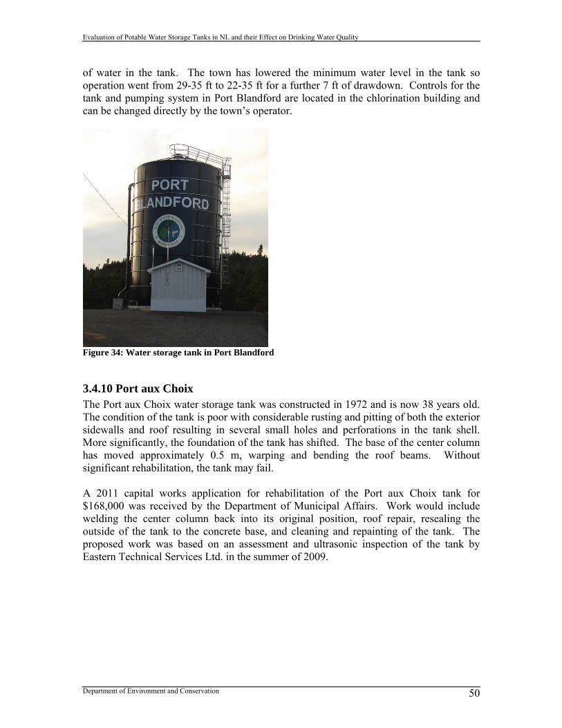
Evaluation of Potable Water Storage Tanks in NL and their Effect on Drinking Water Quality
Department of Environment and Conservation 50
of water in the tank. The town has lowered the minimum water level in the tank so operation went from 29-35 ft to 22-35 ft for a further 7 ft of drawdown. Controls for the tank and pumping system in Port Blandford are located in the chlorination building and can be changed directly by the town’s operator.
Figure 34: Water storage tank in Port Blandford
3.4.10 Port aux Choix The Port aux Choix water storage tank was constructed in 1972 and is now 38 years old. The condition of the tank is poor with considerable rusting and pitting of both the exterior sidewalls and roof resulting in several small holes and perforations in the tank shell. More significantly, the foundation of the tank has shifted. The base of the center column has moved approximately 0.5 m, warping and bending the roof beams. Without significant rehabilitation, the tank may fail. A 2011 capital works application for rehabilitation of the Port aux Choix tank for $168,000 was received by the Department of Municipal Affairs. Work would include welding the center column back into its original position, roof repair, resealing the outside of the tank to the concrete base, and cleaning and repainting of the tank. The proposed work was based on an assessment and ultrasonic inspection of the tank by Eastern Technical Services Ltd. in the summer of 2009.

Evaluation of Potable Water Storage Tanks in NL and their Effect on Drinking Water Quality
Department of Environment and Conservation 51
Figure 35: Port aux Choix tank
3.4.11 Ramea The water storage tank in Ramea was installed in 1999-2000. It is a bolted, glass fused to steel water storage tank. The tank is comprised of multiple ring segments with bolted lap joints for ease of construction. The bolted tank design allows for easy shipping of tank sheets, erection in remote locations, future vertical expansion, relocation, and rapid assembly even in bad weather. There have been recent issues with pinhole leaks in the sidewall of the Ramea water storage tank. This is potentially more of an issue with new bolted steel tanks as opposed to welded steel tanks. A contractor was hired to fix the leaks using a hardwood wedge and a NSF 61 certified caulking compound for sealing.
Figure 36: Ramea water storage tank

Evaluation of Potable Water Storage Tanks in NL and their Effect on Drinking Water Quality
Department of Environment and Conservation 52
3.4.12 Reidville A new water storage tank was built in Reidville in 2002, however, the tank has never been used. Reidville is on a shared water supply with Deer Lake. Water is pumped from the Humber Canal source, to a water filtration plant, through the Deer Lake distribution system and on to Reidville. The tank in Reidville is located at the end of the Reidville distribution system and was built in order to maintain pressure in the system. Due to concerns over maintaining chlorine residual and possible issues with DBPs, the tank has never been used. The cost of construction of the Reidville tank was $580,513. Other towns that have taken or are considering taking their tanks offline (permanently or temporarily) include:
Little Bay Island (considering) Burgeo (considering) Daniel’s Harbour (considering) Harbour Breton (decommissioned) Lawn (decommissioned) Botwood (decommissioned) Glenwood (decommissioned) Trepassey (decommissioned) Burnt Islands (replaced with new tank) Baie Verte (replaced with new tank)
Due to the Reidville tank’s proximity to the Deer Lake airport, for safety reasons, the town had to repaint the roof to make it more visible to aircraft.
3.4.13 St. Alban’s St. Alban’s is on a groundwater well field that pumps to a water storage tank. There is a significant rate of leakage from the St. Alban’s water system. The water system operator rigged a water level indicator on the outside of the tank as shown in Figure 37 for easier monitoring in case of a sudden loss of water in the system.
Figure 37: Water level indicator on St. Alban’s tank

Evaluation of Potable Water Storage Tanks in NL and their Effect on Drinking Water Quality
Department of Environment and Conservation 53
3.4.14 St. Paul’s The town of St. Paul’s has a rectangular in-ground storage tank. A pump at the intake sends water uphill to the tank. As water flows into the tank, it is dosed with chlorine and then feeds the community. There are two separate pipelines leading to and from the tank and all water going to the community has had some residence time in the tank. Water levels in the tank control pump activity at the intake through a pressure transducer. If the system is operating normally, the pumps operate 4 hours on and 4 hours off. St. Paul’s has had problems with DBP levels being over the GCDWQ since samples were first taken in 1998. The town also has trouble maintaining chlorine residuals at the end of the system and with high residuals at the beginning of the system. The St. Paul’s storage reservoir is a rectangular underground concrete tank configured as shown in Figure 38 with separate inlet and outlet, an overflow, vent, chlorine induction pump, and surface chlorination building. When the pump is in operation, water flows into the tank from two discharges on the inlet pipe located 1.5 m from the bottom of the tank. The tank supplies water to the community directly from the outlet pipe located 0.6 m from the bottom of the tank. The close location of the inlet and outlet creates a short circuit within the tank. The chlorine induction pump was also placed high up in the tank, so for operational purposes in order to have chlorine mixed in the tank, water levels need to be kept high. Only 14.3% of the total volume of the tank is currently active with a large inactive volume and very little drawdown.
Figure 38: St. Paul’s tank configuration

Evaluation of Potable Water Storage Tanks in NL and their Effect on Drinking Water Quality
Department of Environment and Conservation 54
3.4.15 Stephenville Crossing In March of 2003, a violent windstorm struck the west coast of Newfoundland and Labrador. At the time of the storm, the Stephenville Crossing standpipe had only recently been commissioned and was gradually being filled so as not to exhaust the groundwater source and pumps at the well field. Without a volume of water in the top portion of the tank, the force of the wind compressed the side of the tank near the top as pictured in Figure 39.
Figure 39: Force of wind compressing Stephenville Crossing standpipe For operational purposes and to prevent a repeat of such an occurrence, the tank in Stephenville Crossing has to remain near full, resulting in very little water turnover in the tank and a large inactive volume. It is highly likely that this tank is violating the ENVC operational guideline of a maximum of 72 hrs of retention time. Stephenville Crossing has a groundwater source with low levels of DOC meaning that excessive water age, loss of chlorine residual, and DBP formation are not an issue for this system. These would be significant issues if the source was surface water with even moderate levels of DOC. The tank constructed in Stephenville Crossing was a bolted, glass fused to steel standpipe. A factory applied silica glass coating to the steel sidewalls of the tank forms a hard, inert barrier on the inside and outside surface of the tank. It protects the steel core of the tank from weathering, corrosion and even graffiti. When the Stephenville Crossing tank buckled in on itself, there was concern that the glass coating cracked at the point of failure and that glass fragments found their way to the tank bottom and the rest of the distribution system. While glass fragments did sink to the bottom of the tank, the riser pipe was located off the bottom of the tank to prevent any sediment or other debris from being drawn into the distribution system. Sampling of the distribution system by ENVC did not result in any glass fragments being found.
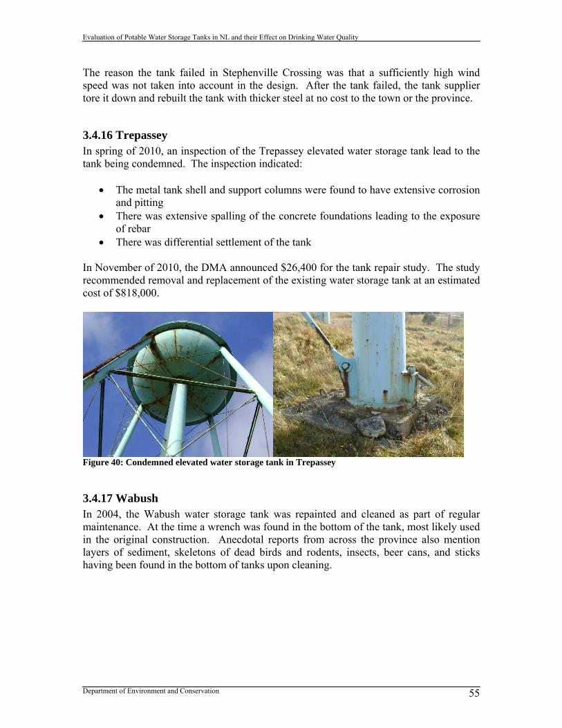
Evaluation of Potable Water Storage Tanks in NL and their Effect on Drinking Water Quality
Department of Environment and Conservation 55
The reason the tank failed in Stephenville Crossing was that a sufficiently high wind speed was not taken into account in the design. After the tank failed, the tank supplier tore it down and rebuilt the tank with thicker steel at no cost to the town or the province.
3.4.16 Trepassey In spring of 2010, an inspection of the Trepassey elevated water storage tank lead to the tank being condemned. The inspection indicated:
The metal tank shell and support columns were found to have extensive corrosion and pitting
There was extensive spalling of the concrete foundations leading to the exposure of rebar
There was differential settlement of the tank In November of 2010, the DMA announced $26,400 for the tank repair study. The study recommended removal and replacement of the existing water storage tank at an estimated cost of $818,000.
Figure 40: Condemned elevated water storage tank in Trepassey
3.4.17 Wabush In 2004, the Wabush water storage tank was repainted and cleaned as part of regular maintenance. At the time a wrench was found in the bottom of the tank, most likely used in the original construction. Anecdotal reports from across the province also mention layers of sediment, skeletons of dead birds and rodents, insects, beer cans, and sticks having been found in the bottom of tanks upon cleaning.

Evaluation of Potable Water Storage Tanks in NL and their Effect on Drinking Water Quality
Department of Environment and Conservation 56
Figure 41: Newly repainted Wabush water storage tank Another issue experienced with the Wabush water storage tank was that is was constantly overflowing. The high water level indicator signal was failing to tell the pump to shut off resulting in wasted water, chlorine disinfectant, energy and money. The issue was with a malfunctioning altitude valve that had not been maintained.
3.4.18 Woody Point In 2010, an inspection was performed on the Woody Point water storage tank by Eastern Technical Services Ltd. The tank dates from approximately 1976, and this was the first time the tank had been opened, cleaned or inspected in approximately 10 years. Approximately 15 cm of silt had accumulated in the bottom of the tank. There was extensive coating failure on the interior and exterior of the tank, and slight corrosion and pitting failure. There was significant failure of the tank roof caused by the collapse of the centre column and roof support beams. The roof concavity was approximately 1 m deep and had collected standing water which was dripping into the tank (see Figure 42). The overflow pipe had also broken off inside the tank (see Figure 43). Water level controls for the tank had also failed.

Evaluation of Potable Water Storage Tanks in NL and their Effect on Drinking Water Quality
Department of Environment and Conservation 57
Figure 42: Woody Point tank roof failure
Figure 43: Interior of Woody Point tank including sediment accumulation and broken overflow pipe
3.5 Maintenance of Tanks in NL For the majority of communities in Newfoundland and Labrador, tank maintenance occurs when there is an issue with a tank and is neither pre-planned nor preventative. Regular tank maintenance is also dependent on the water system operator and how active the operator is in undertaking inspection and maintenance activities. Larger towns also tend to be more proactive in the maintenance of their water storage tanks. Table 8 contains a list of known major maintenance work done on tanks in the province since 1994. Comprehensive tank maintenance includes such tasks as tank cleaning, painting (interior and exterior), roof repair, and general repair. Only 18 out of 95 communities with tanks have applied for permits to undertake comprehensive tank maintenance since 1994. The frequency of such maintenance work varies between every 7-25 years. Tanks in some communities may only be cleaned once every 25 years when comprehensive maintenance work is needed. In-ground tanks tend to get cleaned more often then other types of tanks. For example, the Cape St. George in-ground tank is

Evaluation of Potable Water Storage Tanks in NL and their Effect on Drinking Water Quality
Department of Environment and Conservation 58
cleaned on an annual basis with chlorine and a broom. There are currently a large number of older tanks in the province that either need to be refurbished, or removed and replaced. Table 8: Comprehensive tank maintenance in NL Town Construction
Cost ($) Year Description
St. Bernard- Jacques Fontaine
18,630 2000 Tank cleaning and painting
New-Wes-Valley 67,160 1999 Reservoir painting New-Wes-Valley 185,546* 2009 Exterior repainted Lumsden 57,132 2000 Reservoir painting Burin 111,145 2007 Exterior painting Rose Blanche 393,300 2009 Tank reconstruction Wabush 167,900 2004 Tank painting and cleaning Whitbourne 268,187 2010 Tank repainting Port aux Choix 127,916 2010 Tank refurbished Appleton 99,946 2007 Tank exterior painted King’s Point 37,539* 2003 Tank cleaned and painted Pilley’s Island 33,016 2005 Exterior repainted and 3mm steel plate
added to top of tank Triton 318,942 2008 New roof, tank cleaned and painted Bonavista - 1995 Tank cleaned and painted New Perlican - 2009 Tank interior cleaned and painted St. John’s - 2003 Tank interior and exterior cleaned and
painted Corner Brook - 2000 Tank cleaned and painted Corner Brook - 2007 Tank cleaned and painted St. George’s - 1994 Tank refurbished * May include engineering costs in addition to construction costs The cost of comprehensive tank maintenance is considerable, varying between approximately 10-50 percent of the capital cost of the tank. Preventative tank maintenance can save a community costly repairs and extend the life of the tank considerably. The tank in Hawke’s Bay dates from 1974, giving it an active life of 36 years to date. There are other older tanks in the province, dating back to around World War II, however, their exact age is unknown. Corrosion of water storage tanks is a major problem in Newfoundland and Labrador. The combination of chlorinated and low pH water on the inside of the tank can lead to rapid rusting of roof trusses and metal loss in steel plates of the tank. The ocean influenced environment of the province is also very corrosive to the outside of steel tanks. If preventative maintenance is not practiced, it can lead to rapid deterioration in the condition of the water storage tank. Practically all major tank maintenance work undertaken in the province was related to tank corrosion.

Evaluation of Potable Water Storage Tanks in NL and their Effect on Drinking Water Quality
Department of Environment and Conservation 59
Sediment build-up in tanks is also an issue as it relates to water quality management in the distribution system. Operators should know the rate of sedimentation in their tanks as this will inform how often the interior of the tank needs to be cleaned. In the Hawke’s Bay tank, up to 15 cm of accumulated sediment has been observed over an unknown timeframe. Types of vandalism of concern with water storage tanks are any dents in the tank shell from vehicles hitting the tank, dimples in the tank shell from thrown rocks, bullet holes from guns, graffiti spray painted on the tank, and children or teenagers hanging out around tanks (climbing tank, poking sticks or beer cans in holes, etc.). Although not all water storage tanks in the province are protected by locked fences, there has been very little evidence of vandalism of tanks. One exception is evidence of graffiti on the Point Leamington tank pictured in Figure 44, and on other unsecured tanks located in residential areas (Mount Pearl, Gander).
Figure 44: Graffiti on the Point Leamington tank According to a recent study commissioned by ENVC examining how operation and maintenance of water distribution and treatment infrastructure affects resulting drinking water quality, operators should be spending approximately 40.5 hours per year on operation and maintenance activities relating to water storage tanks (CRA, 2010).
3.6 Water Quality Issues and Tanks in NL No specific drinking water quality event has ever been linked to a water storage tank in the province. The potential for pathogenic contamination or a spike in turbidity is a possibility, however. Water storage tanks have been implicated in several waterborne disease outbreaks in both the US and Europe (USEPA, 2002). Tanks have a major influence on the resulting drinking water quality provided to users on the water distribution system. Unfortunately, most towns are unaware of how their water storage tank is affecting their drinking water quality.

Evaluation of Potable Water Storage Tanks in NL and their Effect on Drinking Water Quality
Department of Environment and Conservation 60
The main drinking water quality issues associated with tanks in the province include:
Formation of disinfection by-products Loss of chlorine residuals Taste and odor complaints due to stagnation
3.6.1 Tanks and Disinfection By-Products The following sections examine the effect of tanks on both THMs and HAAs, which comprise the largest fraction of DBPs by weight in drinking water. 3.6.1.1 THMs A nonparametric statistical analysis (Mood’s median test) was performed to see if there was any difference in THM levels from serviced areas with water storage tanks and those without. A nonparametric test was used in the analysis as DBP data has a non-normal distribution with outliers. This analysis was then refined to only look at serviced areas with or without tanks that were chlorinating. The analysis was further refined to separate serviced areas supplied by surface water and groundwater sources, with or without tanks, and that are chlorinating. Average THM values over the entire period of record from the ENVC drinking water quality database were used going back to 1993. Table 9: Mood’s median test of average community THMs with storage tank presence as analysis factor
Presence of Storage Tank
Number of Serviced Areas
Median THM- µg/L (Q3-Q1)
p-value
No Tank 361 38.6 (80.6) Tank 99 67.7 (92.0)
0.002*
No Tank- chlorinating 334 42.5 (82.4) Tank- chlorinating 98 68.1 (92.4)
0.039*
No Tank- surface water 214 70.4 (73.6) Tank- surface water 78 91.1 (86.5)
0.290
No Tank- groundwater 120 3.1 (9.2) Tank- groundwater 20 2.1 (24.3)
0.629
* statistically significant at α < 0.05 The median THM level for systems with tanks was significantly higher than for systems without tanks. After refining the analysis to exclude systems that are not chlorinating, results still indicated that THMs were significantly higher for systems with tanks as indicated in Table 9. Further refinements looking exclusively at surface water and groundwater systems, indicated that there was no significant difference in median THMs with or without tanks. A significant difference in THM medians was not detected for surface water systems chlorinating with tanks and those without at the α = 0.05 level, however, the median THM value was still higher for surface water systems with tanks. THMs are expected to be higher in surface water systems and will continue to form in the distribution system given chlorine, DOC and continued residence time. Water storage tanks provide increased residence time and aging of water in the distribution system,

Evaluation of Potable Water Storage Tanks in NL and their Effect on Drinking Water Quality
Department of Environment and Conservation 61
enough to significantly increase THM levels in communities in Newfoundland and Labrador with tanks. A nonparametric statistical analysis (Mood’s median test) was also performed to see how the water storage tank location on the distribution system affected THM levels in the province. The results in Table 10 indicate that there is no significant difference in THM levels based on the tank location. However, median THMs were higher in networks where the tank was located at the end of the system as was expected. Tanks located at the beginning of the distribution system displayed the next highest median THMs, the lowest observed THMs occurred where tanks are in the middle of the distribution system. Tanks located at the start of the system are the first to receive water that has been dosed with chorine. The availability of high levels of free chlorine just after dosing, and the residence time of water in the tank, provides excellent conditions for THM formation. The formation potential is reduced when the tanks are located toward the middle of the distribution system possibly because of the sharp reduction in available chlorine after dosing observed in most systems. Tanks located at the end of the system generally experience less demand, longer residence times and movement of the same water in and out of the tank resulting in longer residence times and higher observed median THMs. Table 10: Mood’s median test of average community THMs with storage tank location as analysis factor
Location of Tank on System
Number of Surface Water fed Serviced Areas that
are Chlorinating
Median THM- µg/L (Q3-Q1)
p-value
Beginning 41 94 (94) Middle 38 62 (59) End 8 103 (108)
0.073
* statistically significant at α < 0.05 3.6.1.2 HAAs A nonparametric statistical analysis (Mood’s median test) was performed to see if there was any difference in HAA levels from serviced areas with water storage tanks and those without. This analysis was then refined to only look at serviced areas that were chlorinating either with or without tanks. The analysis was further refined to separate serviced areas supplied by surface water and groundwater sources, with or without tanks, and that are chlorinating. Average HAA values over the entire period of record from the ENVC drinking water quality database were used going back to 1999. Table 11: Mood’s median test of average community HAAs with storage tank presence as analysis factor
Presence of Storage Tank
Number of Serviced Areas
Median HAA- μg/L (Q3-Q1)
p-value
No Tank 338 40.0 (109.0) Tank 101 90.3 (119.1)
0.000*
No Tank- chlorinating 316 46.3 (121.3) Tank- chlorinating 100 91.5 (118.7)
0.000*

Evaluation of Potable Water Storage Tanks in NL and their Effect on Drinking Water Quality
Department of Environment and Conservation 62
No Tank- surface water 203 89.4 (106.9) Tank- surface water 80 107.7 (104.8)
0.105
No Tank- groundwater 113 0.0 (3.5) Tank- groundwater 20 0.0 (0.0)
0.357
* statistically significant at α < 0.05 As indicated in Table 11, a significant difference in HAA medians was detected between systems with tanks and those without tanks, and chlorinating systems with tanks and those without. Systems with tanks had significantly higher HAAs, reflecting the pattern observed with THMs. A significant difference in HAA medians was not detected for surface water systems chlorinating with tanks and those without at the α = 0.05 level, however, the median HAA value was still higher for surface water systems with tanks. No difference in median HAAs was observed on groundwater systems with or without tanks. Unlike THMs, HAAs will decay in the distribution system due to microbial decomposition by the pipe biofilm and lack of chlorine residual (ENVC, 2010). The longer residence time provided by the tank may be affecting HAA decay to some extent. A nonparametric statistical analysis (Mood’s median test) was also performed to see how the water storage tank location on the distribution system affected HAA levels in Newfoundland and Labrador. The results in Table 12 indicate that there was no significant difference in HAAs based on where the tank was located, however, the highest medians were observed where the tank was located at the end of the system. Tanks located at the beginning of the distribution system had the next highest HAAs, and tanks in the middle the lowest, mirroring results for THMs. Table 12: Mood’s median test of average community HAAs with storage tank location as analysis factor
Location of Tank on System
Number of Surface Water fed Serviced Areas that
are Chlorinating
Median HAA- ug/L (Q3-Q1)
p-value
Beginning 42 110 (116) Middle 39 69 (79) End 8 137 (136)
0.108
* statistically significant at α < 0.05
3.6.2 Tanks and Chlorine Residuals Many communities have difficulty managing chlorine residuals on systems with tanks. Depending on the configuration of the system, the community is sometimes only dosed with chlorine (at high levels) while the pump is active and filling the tank. Often when the tank is feeding the system, communities find it difficult to maintain chorine residuals at the extremities of the system as the chorine has decayed over time in the tank. Table 13 indicates that there is a significant difference in median free chlorine residuals (using all data in the period of record going back to 1993) in surface water systems that are chlorinating and that have tanks versus those that do not. Systems with tanks have

Evaluation of Potable Water Storage Tanks in NL and their Effect on Drinking Water Quality
Department of Environment and Conservation 63
significantly higher free chlorine residuals. Possible explanations for this include that larger systems tend to have tanks where operators pay more attention to maintaining chlorine residuals. Also, on systems where water is fed to the community and tank at the same time, chlorine is most likely being dosed at higher levels in order to maintain residuals when the tank is feeding the system. Table 13: Mood’s median test of average free chlorine residual with storage tank presence as analysis factor
Presence of Tank Number of Surface Water fed Serviced Areas that
are Chlorinating
Median Free Chlorine- mg/L (Q3-Q1)
p-value
No tank 221 0.23 (0.340) Tank 81 0.410 (0.370)
0.000*
* statistically significant at α < 0.05 The location of the tank was also investigated as a factor affecting free chlorine residuals on the distribution system. Although no significant difference in medians was detected as shown in Table 14, it is of interest that the highest median chlorine residuals were found to be on distribution networks where the tank is located at the end of the system. This result indicates that there is more decay of chlorine with the tank towards the beginning of the system. Table 14: Mood’s median test of average free chlorine residual with storage tank location as analysis factor
Location of Tank on System
Number of Surface Water fed Serviced Areas that
are Chlorinating
Median Free Chlorine- mg/L
(Q3-Q1)
p-value
Beginning 42 0.395 (0.298) Middle 42 0.350 (0.450) End 8 0.475 (0.368)
0.229
* statistically significant at α < 0.05
4.0 Water Storage Tank Modeling Modeling of water storage tanks encompasses two different types of models that provide very different outputs. The two different types of models include:
1. Water Distribution System Models All elements of the water distribution system are modeled Outputs include hydraulic and water quality behavior Used to evaluate tank performance and operation with respect to the rest of
the distribution network
2. Computational Fluid Dynamics Models Only the tank is modeled Outputs include behavior of fluid in the tank

Evaluation of Potable Water Storage Tanks in NL and their Effect on Drinking Water Quality
Department of Environment and Conservation 64
Used to evaluate tank mixing The following sections discuss the different types of tank modeling in more detail.
4.1 Water Distribution System Models with Tanks Water distribution system models are computer models that can simulate the hydraulic and water quality behaviour of water distribution networks. They can be used for a number of purposes including modeling of tank behaviour, tracking of chemical constituents in water, fire flow analysis, identifying operational problems, and system design. There are a variety of water distribution system models on the market that vary in price from tens of thousands of dollars to free shareware including:
EPANET (free) MIKE URBAN InfoWorks WaterCAD Water Networks WaterGEMS
In distribution system modeling, the tank is just one component of the network including the source, pumps, pipes, demand, etc. The distribution system model will show the user how the tank is operating, but also how the tank operation is affecting the other components in the system. Information required for modeling a tank in a distribution system is highlighted in Table 15 (Rossman, 2000). Table 15: Tank information required in a distribution system model Component Parameters Data Source Comments
Storage Tanks Elevation Dimensions Max and min water levels Initial water level in tank Tank mixing model
(complete mixing, plug flow, 2 compartment mixing)
Drawings Site survey Field testing
Can be difficult to measure storage volume with depth based on tank shape
The following section examines how the water storage tank is operating in a local community using a distribution system model.

Evaluation of Potable Water Storage Tanks in NL and their Effect on Drinking Water Quality
Department of Environment and Conservation 65
4.1.1 Brighton The Brighton water distribution system is a linear system approximately 4 km long. Water is dosed with chlorine in the pump house next to the reservoir and then pumped uphill to the tank and the town. When the pump cuts out, water is fed to the town directly from the tank. The configuration of the Brighton distribution system is indicated in Figure 45.
Figure 45: Brighton distribution system The coordination of the tank and pump are displayed in Figure 46 and Figure 47. When the tank water level gets to 5.5 m, the pump cuts out with flow dropping to 0 L/s and the tank water level begins to drop. Once the tank water level reaches 1.83 m, the pump is triggered and the tank begins to fill again. It takes approximately 6-9 hours for the tank to fill and 27-32 hours for it to empty.
Figure 46: Pressure in the Brighton tank
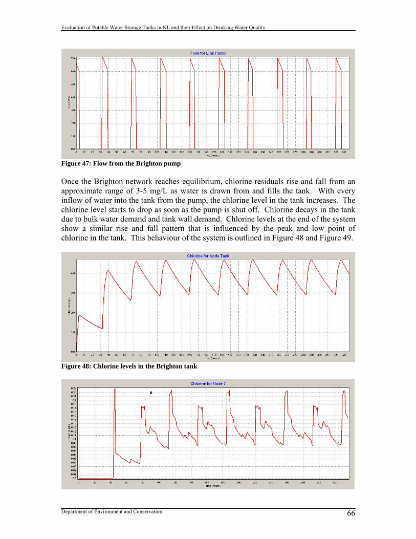
Evaluation of Potable Water Storage Tanks in NL and their Effect on Drinking Water Quality
Department of Environment and Conservation 66
Figure 47: Flow from the Brighton pump Once the Brighton network reaches equilibrium, chlorine residuals rise and fall from an approximate range of 3-5 mg/L as water is drawn from and fills the tank. With every inflow of water into the tank from the pump, the chlorine level in the tank increases. The chlorine level starts to drop as soon as the pump is shut off. Chlorine decays in the tank due to bulk water demand and tank wall demand. Chlorine levels at the end of the system show a similar rise and fall pattern that is influenced by the peak and low point of chlorine in the tank. This behaviour of the system is outlined in Figure 48 and Figure 49.
Figure 48: Chlorine levels in the Brighton tank

Evaluation of Potable Water Storage Tanks in NL and their Effect on Drinking Water Quality
Department of Environment and Conservation 67
Figure 49: Chlorine levels at the end of the Brighton system As indicated in Figure 50, 34.7% of chlorine decay in the Brighton distribution system is due to the loss of chlorine residual in the water storage tank.
Figure 50: Contributions to chlorine decay in the Brighton system The water age in the tank fluctuates with the filling and drawing of water from the tank as shown in Figure 51. The maximum water age in the Brighton tank is 57.5 hours. Maximum water age at the end of the Brighton system is 102.5 hours as indicated in Figure 52. Water age at the end of the system displays a deep trough of younger water when the pump is in operation and feeding the distribution system. Water age increases sharply when water from the tank feeds the town and makes its way to the end of the system. It takes approximately 40-45 hours for water from the tank or pump to make its way to the end of the Brighton network.
Figure 51: Water age in the Brighton tank

Evaluation of Potable Water Storage Tanks in NL and their Effect on Drinking Water Quality
Department of Environment and Conservation 68
Figure 52: Water age at the end of the Brighton system Figure 53 and Figure 54 provide profiles of free chlorine and water age throughout the Brighton distribution network from the tank to the end of the system during a time when the tank is filling. As indicated, the chlorine level coming directly from the pump house and entering the network is higher than the level in the tank at 6.28 mg/L. There is a sharp decline in chlorine at the beginning of the system. Water age in the tank is more than that coming from the pump house. Water age steadily increases throughout the system; however, it remains fairly steady through the middle of the network.
Figure 53: Profile of free chlorine in the Brighton network when the tank is filling

Evaluation of Potable Water Storage Tanks in NL and their Effect on Drinking Water Quality
Department of Environment and Conservation 69
Figure 54: Profile of water age in the Brighton network when the tank is filling Figure 55 and Figure 56 provide profiles of chlorine level and water age throughout the Brighton distribution system from the tank to the end of the system during a time when the tank is emptying. Chlorine entering the network is reduced to 4.34 mg/L as it is now coming from the tank rather than directly from the pump house. Chlorine levels steadily deteriorate, but at a much slower rate then when the system was fed by the pump house. Also, chlorine levels actually increase at the very end of the system. This is due to a plug of older water that came from the tank making its way through the distribution system. The water at the end of the system is actually younger, has experienced less chlorine decay, and therefore has a higher chlorine level. The dip in water age in the first quarter of the system is due to a plug of young water input into the network from when the system was being fed from the pump house.
Figure 55: Profile of free chlorine in the Brighton network when the tank is emptying
Figure 56: Profile of water age in the Brighton network when the tank is emptying Figure 57 traces the percentage of flow at the end of the network that originated from the tank. The pattern in the graph indicates that at the end of the Brighton network large plugs of water originate 100% from the tank, interspersed with small plugs of water originating 96% from the source reservoir when the pump is feeding the system.

Evaluation of Potable Water Storage Tanks in NL and their Effect on Drinking Water Quality
Department of Environment and Conservation 70
Figure 57: Percentage of water at the end of the Brighton network that originated from the tank In addition to evaluating how the tank is currently affecting the operation of the water distribution system, the network model can also be used to determine how changes in the tank operation will affect the system, either negatively or positively. Changes to the tank that can be modeled include:
Altering the maximum and minimum water levels Altering the location of the tank Altering the volume of the tank Altering how the mixing of water in the tank is modeled Altering inlet velocity into the tank Simulating a chlorine booster in or near the tank Altering the tank filling and emptying cycle by adjusting the pump settings
4.2 CFD Modeling of Tanks Computational Fluid Dynamic (CFD) modeling uses numerical methods and algorithms to solve and analyze problems that involve fluid flow. CFD models solve the dynamic behavior of liquids and gases in two or three-dimensions (using Navier-Stokes based solvers for example) based on the fundamental laws of mass, momentum and energy conservation. There is a variety of CFD software available ranging from academic shareware to commercial software costing in excess of $50,000. CFD models on the market and in common use in the design and evaluation of water storage tanks include:
Flow3D Fluent CFDesign CFX Answer Cfdesign Star-cd Caedium

Evaluation of Potable Water Storage Tanks in NL and their Effect on Drinking Water Quality
Department of Environment and Conservation 71
CFDlab (academic) EacyCFD (academic)
CFD models can be used in the design and operational evaluation of water storage tanks. Typically, CFD models are used to evaluate mixing in the water storage tank based on inlet/outlet configuration or the use of mixing devices. Outputs include modeled profiles of water velocity, temperature or tracer concentration in the tank. While the supplier may provide standard shop drawings for different standard tank components, the consultant is still responsible for the design of the tank inlet and outlet configuration and tank mixing system. To date, no consultant has used CFD modeling to demonstrate that complete mixing of water occurs within the designed tank. It is recommended that a tank mixing system be considered in certain situations (residual loss in the network, high DBPs, standpipes, tank at end of network, mixed source waters) and that this system must be validated to demonstrate complete mixing. CFD models are an important tool that can be used to demonstrate this and to optimize water storage tank design. CFD models of mixing in tanks with similar designs to those found in Newfoundland and Labrador are presented in Figure 58 to Figure 63. The stratification of water in a filling standpipe is demonstrated in Figure 58. Figure 59 to Figure 61 show how duckbill valves on the inlets can create jets that extend the height or width of the tank, encouraging greater mixing throughout the tank. Figure 62 and Figure 63 show how a mixing device placed in the tank promotes greater mixing.
Figure 58: Water velocity in standpipe with bottom inlet (Courtesy of Red Valve Co.)

Evaluation of Potable Water Storage Tanks in NL and their Effect on Drinking Water Quality
Department of Environment and Conservation 72
Figure 59: Turbulent mixing in water storage tank with 2 vertical Tideflex® duckbill valves on inlets
Figure 60: Turbulent mixing in water storage tank with horizontal Tideflex® duckbill valve
Figure 61: Tank mixing with elevated inlets with 4 horizontal Tideflex® duckbill valves

Evaluation of Potable Water Storage Tanks in NL and their Effect on Drinking Water Quality
Department of Environment and Conservation 73
Figure 62: Mixing streamlines in a 300,000 Gal tank using a PAX Water Technologies mixing device
Figure 63: 2MG tank with no mixing (left) and with Solar Bee mixing device (right)
4.2.1 St. Paul’s A 2 dimensional CFD model of the in-ground water storage tank in St. Paul’s was developed in order to get a better understanding of what was happening inside the tank. The configuration of the St. Paul’s water storage tank is depicted in Figure 38. Water flows into the tank from two discharges on the inlet pipe located 1.5 m from the bottom of the tank. The tank supplies water to the community directly from the outlet pipe located 0.6 m from the bottom of the tank. The close location of the inlet and outlet creates a short circuit within the tank as shown in Figure 64.

Evaluation of Potable Water Storage Tanks in NL and their Effect on Drinking Water Quality
Department of Environment and Conservation 74
Figure 64: Mixing in the St. Paul’s water storage tank with existing configuration Different configurations of the inlet and outlet on the St. Paul’s tank were also modeled to see if they promoted better mixing. With the inlet and outlet on opposite sides of the tank and at a diagonal, water tends to flow along the side of the tank until it reaches the outlet leaving a large dead zone of water in the middle as shown in Figure 65. With the inlet and outlet directly opposite from each other, water tends to flow in a straight line through the middle of the tank, with small dead zones on either side as shown in Figure 66.
Figure 65: Mixing in the St. Paul’s water storage tank with inlet and outlet opposite and diagonal
St. Paul’s Water Storage Tank: Dimensions: 12 x 5 m Inlets: 2 Outlets: 1
Outlet
Inlet Inlet
Dead Zone
Dead Zone
Dead Zone
Dead Zone
Dead Zone
Inlet
Outlet

Evaluation of Potable Water Storage Tanks in NL and their Effect on Drinking Water Quality
Department of Environment and Conservation 75
Figure 66: Mixing in the St. Paul’s water storage tank with inlet and outlet on opposite sides of tank
5.0 Recommendations A number of the issues with water storage tanks observed in the province in Section 4 of this report relate directly to flaws in the tank design and inadequacies in tank operation and maintenance. General recommendations for the improvement of tank design, construction, operation and maintenance include the following:
1. Revise the potable water storage section in the Design Guidelines. 2. DMA should develop a generic tank specification that encompasses steel bolted,
steel welded and concrete tanks (either collectively or separately) and that meets minimum requirements of the ENVC Design Guidelines and AWWA Standards. This specification should be added to the Master Specification document.
3. Revise the application form for permits to construct to expand on the
information required for water storage tanks.
4. Develop a water storage tank design evaluation tool and checklist to ensure new designs for water storage tanks meet design requirements.
5. Develop Standard Operating Procedures specifically for water storage tanks for
the use of community water system operators.
6. Update the water system operator classroom education seminar on water storage tanks and develop a hands-on training session specific to water storage tanks.
7. Develop a specific term or condition relating to water storage tanks for Permits
to Operate.
Dead Zone
Dead Zone
Inlet Outlet
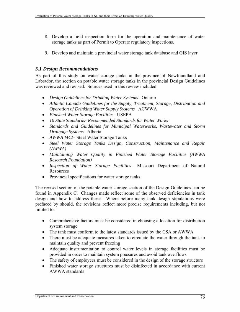
Evaluation of Potable Water Storage Tanks in NL and their Effect on Drinking Water Quality
Department of Environment and Conservation 76
8. Develop a field inspection form for the operation and maintenance of water
storage tanks as part of Permit to Operate regulatory inspections.
9. Develop and maintain a provincial water storage tank database and GIS layer.
5.1 Design Recommendations As part of this study on water storage tanks in the province of Newfoundland and Labrador, the section on potable water storage tanks in the provincial Design Guidelines was reviewed and revised. Sources used in this review included:
Design Guidelines for Drinking Water Systems– Ontario Atlantic Canada Guidelines for the Supply, Treatment, Storage, Distribution and
Operation of Drinking Water Supply Systems– ACWWA Finished Water Storage Facilities– USEPA 10 State Standards- Recommended Standards for Water Works Standards and Guidelines for Municipal Waterworks, Wastewater and Storm
Drainage Systems– Alberta AWWA M42– Steel Water Storage Tanks Steel Water Storage Tanks Design, Construction, Maintenance and Repair
(AWWA) Maintaining Water Quality in Finished Water Storage Facilities (AWWA
Research Foundation) Inspection of Water Storage Facilities– Missouri Department of Natural
Resources Provincial specifications for water storage tanks
The revised section of the potable water storage section of the Design Guidelines can be found in Appendix C. Changes made reflect some of the observed deficiencies in tank design and how to address these. Where before many tank design stipulations were prefaced by should, the revisions reflect more precise requirements including, but not limited to:
Comprehensive factors must be considered in choosing a location for distribution system storage
The tank must conform to the latest standards issued by the CSA or AWWA There must be adequate measures taken to circulate the water through the tank to
maintain quality and prevent freezing Adequate instrumentation to control water levels in storage facilities must be
provided in order to maintain system pressures and avoid tank overflows The safety of employees must be considered in the design of the storage structure Finished water storage structures must be disinfected in accordance with current
AWWA standards

Evaluation of Potable Water Storage Tanks in NL and their Effect on Drinking Water Quality
Department of Environment and Conservation 77
5.2 Recommendations for Permit to Construct Applications The current application for a permit to construct deals with water storage tanks in Section B-10. The application only requires information on the type of tank and volume. The following information should also be requested for water storage tanks:
Tank location coordinates Tank dimensions Tank bottom elevation Maximum water level Minimum water level Average fill rate into tank
A revised permit to construct application form requesting the above information can be found in Appendix D.
5.3 Tank Design Evaluation Tool and Checklist In order to evaluate the design of new potable water storage tanks, ENVC has developed the following two evaluation tools:
1. Potable Water Storage Tank Design Checklist 2. Tank Design Evaluation Tool
The Checklist can be used to ensure design requirements from the provincial Design Guidelines for potable water storage tanks have been met. New storage tanks must undergo a design review in order to be issued with a Permit to Construct from ENVC. During this review, the checklist can be used to identify any deficiencies in the storage tank design submitted. Once any design issues identified with the aid of the checklist have been addressed, the permit can then be issued. A copy of the Checklist can be found in Appendix E. Further to the checklist, ENVC has also developed a spreadsheet based Tank Design Evaluation Tool. This tool requires a range of inputs as outlined in Table 16. This information should be available from the design submission submitted to ENVC. While the tool mainly focuses on the design of the tank, there is limited evaluation of the operation of the tank as well. A similar tool has been developed and is described in Mahmood et al, 2009. Table 16: Input information required for the Tank Design Evaluation Tool
Town Population serviced Tank Type- standpipe, in-ground, elevated, reservoir Tank location- beginning, middle, end Tank elevation (m) - at bottom water surface Separate inlet/outlet Tank level control

Evaluation of Potable Water Storage Tanks in NL and their Effect on Drinking Water Quality
Department of Environment and Conservation 78
Mixing device Tank shape: C- cylindrical, R- rectangle, S- sphere Tank dimensions -rectangular- l (m) -rectangular- w (m) -rectangular- h (m) -cylindrical- d (m) -cylindrical- h (m) -spherical- d (m) Capacity (m3) Riser height (m) Maximum water level (m) Minimum water level (m) Fill time- one cycle (hrs) Emptying time- one cycle (hrs) Inlet diameter (mm) Average fill rate (L/s) Inlet orientation- vertical, horizontal, angle Path of inflow jet- maximum, minimum, tangential, obstructed Average daily demand- metered (m3/d) The tool then uses the required input data to evaluate the design and performance of the tank including an evaluation of the following factors:
Storage capacity Residence time in the tank Fill time and how this affects mixing Volume turnover in the tank Inlet momentum and how this affects mixing Whether the inflow is turbulent or not Inlet configuration and how this affects mixing
The evaluation reported for each factor is poor, marginal or good as determined from the criteria listed in Table 17 to Table 19.

Evaluation of Potable Water Storage Tanks in NL and their Effect on Drinking Water Quality
Department of Environment and Conservation 79
Table 17: Tank evaluation criteria– poor
Grade Type Poor
Storage greater or less than 80-120 % required
Residence time greater than 72 hrs
Fill time less than 80 % of required fill time
Volume turnover less than 80 % of required volume turnover
Inlet momentum less than 0.0086 m4/s2
Turbulent inflow (at 5ºC) less than 3.58 L/s-m
Inlet configuration flow path along minimum length or obstructed Table 18: Tank evaluation criteria– marginal
Grade Type Marginal
Storage 80-120 % required
Residence time 72-24 hrs
Fill time greater than 80 % of required fill time
Volume turnover greater than 80 % of required volume turnover
Inlet momentum 0.0086-0.026 m4/s2
Turbulent inflow (at 5ºC)
Inlet configuration tangential flow path Table 19: Tank evaluation criteria– good
Grade Type Good
Storage required = capacity
Residence time less than 24 hrs
Fill time actual fill time > required fill time
Volume turnover actual volume turnover > required volume turnover
Inlet momentum greater than 0.026 m4/s2
Turbulent inflow (at 5ºC) greater than 3.58 L/s-m
Inlet configuration flow path along maximum length A copy of the Tank Design Evaluation Tool environment can be found in Appendix E, including all equations used to calculate required values and evaluation factors. The tool developed is meant to be used for evaluation and not the actual design of potable water storage tanks.
5.4 Standard Operating Procedures Recommendations One of the major issues with potable water storage tanks in the province is the lack of proper attention paid to operation and maintenance. Water storage tanks are often the most expensive and visible part of a drinking water distribution system, and as such, should be looked after. The life expectancy of a water storage tank can exceed 100 years (depending on the material) if the tank is properly maintained. Too often in the province, minor issues with tanks that could have been addressed by routine maintenance activity

Evaluation of Potable Water Storage Tanks in NL and their Effect on Drinking Water Quality
Department of Environment and Conservation 80
are allowed to become major issues that require extensive rehabilitation of the tank, or in some cases demolition and removal. Devices to control and indicate water level should be incorporated into the design and construction of all tanks. Automatic control of water level in storage tanks offers significant advantages over manual control. Operators must also be knowledgeable of how to change set water levels (high water level, low water level) on their tanks for greater operational control, and have an understanding of the operational range their tank can work within. To assist community water system operators, ENVC has developed a generic Standard Operating Procedure (SOP) specifically for water storage tanks. This is part of a larger initiative of ENVC to develop generic SOP for various common components of a water distribution system. The SOP for water storage tanks:
Identifies useful secondary resources and references Highlights operational performance measures that should be monitored Identifies issues to look out for in water storage tank operation Highlights maintenance activities for altitude valves Identifies tank inspection frequency and activities Identifies tools that can be used in inspections Outlines how to empty a water storage tank
A copy of the text of the SOP for water storage tanks can be found in Appendix F.
5.5 Training Recommendations Although the Operator Education, Training and Certification (OETC) section discusses water storage tanks as part of their classroom education seminars on water distribution systems, it is recommended that the section on water storage tanks be expanded. A revised presentation on water storage tanks can be developed based on this report and the presentation delivered at the 2010 Drinking Water Workshop in Gander by ENVC. In addition, a hands-on training session specific to water storage tanks should be developed and delivered in the field for all communities with water storage tanks. This training session should be based on the SOP developed for water storage tanks.
5.6 Permit to Operate Recommendations If a Permit to Operate for Water Distribution has been issued for a community without any mention of a water storage tank identified by ENVC, it is recommended that this Permit to Operate be re-issued. It is recommended that a separate section of terms or conditions specific to water storage be developed for Permits to Operate for Water Distribution. This section should be incorporated into any new or revised Permits to Operate for Water Distribution issued for a drinking water system with a finished water

Evaluation of Potable Water Storage Tanks in NL and their Effect on Drinking Water Quality
Department of Environment and Conservation 81
storage tank. The section should be entitled Water Storage and should include the following terms or conditions:
The town shall monitor and record the operational conditions of the water storage tank including the water level, time to fill/empty the tank, occurrence of overflows, occurrence of alarms, ice formation, and water quality in the tank. If necessary the town shall modify tank operating conditions in order to address any issues or optimize performance. If not present, the town should pursue the incorporation of a SCADA system to aid with monitoring and operation of the water storage tank.
The town shall establish a preventative maintenance program for all water storage
tanks outlining the frequency, procedures and maintenance of records for tank inspections. Routine tank inspections shall occur weekly, periodic inspections annually, and comprehensive inspections including tank cleaning at least every 5 years. Inspections shall assess tank sanitary, structural, safety, coatings and security conditions.
The town shall ensure that all tank appurtenances including overflows, vents,
access hatches, drains, ladders, fall prevention devices, handrails, fences, locks, ladder guards, control devices, alarms, sensors, mixing systems, isolation valves, and freeze prevention devices are maintained and kept in good working order. Vegetation around the outside of the tank will be removed.
The town shall ensure that the operator has received all necessary safety training
in order to undertake operation and maintenance activities relating to the tank. The provincial Auditor General has highlighted lack of regulatory inspection in general as an issue for ENVC. Currently, there is minimal regulatory field inspection work undertaken by ENVC with respect to Permits to Operate. It is recommended that a regulatory inspection program for Permits to Operate be developed by the Community Water & Wastewater Section with consideration of inspection priorities, field inspection sheets, non-compliance protocols, system feedback to the DMA for capital works ranking, system feedback to the OETC section for training priorities, and system feedback to the Department of Government Services on BWAs.
5.7 Recommendations for Tank Database and GIS Layer Similar to other databases of water and sewer infrastructure (drinking water treatment plants, intakes, wastewater treatment plants, outfalls) it is recommended that a database of water storage tanks be developed and updated on a regular basis. This database can be posted on the Water Resources Management Division (WRMD) web site. The WRMD has also developed a Water Resources Portal which includes a web-based GIS mapping application in which information about geo-referenced entities (protected areas, outfalls, etc.) can be displayed visually. The tank database should include tank

Evaluation of Potable Water Storage Tanks in NL and their Effect on Drinking Water Quality
Department of Environment and Conservation 82
location coordinates so that it can be converted into a GIS layer for integration in the Water Resources Portal.

Evaluation of Potable Water Storage Tanks in NL and their Effect on Drinking Water Quality
Department of Environment and Conservation 83
References ACWWA, 2004, Atlantic Canada Guidelines for the Supply, Treatment, Storage, Distribution and Operation of Drinking Water Supply Systems, ACWWA, Halifax, NS. Alberta Environment, 2006, Standards and Guidelines for Municipal Waterworks, Wastewater and Storm Drainage Systems, Drinking Water Branch, Edmonton, AB. AWWA, 1998, Manual of Water Supply Practices– M42– Steel Water Storage Tanks, AWWA, Denver, USA. AWWA, 2010, Steel Water Storage Tanks Design, Construction, Maintenance and Repair, McGraw Hill, New York, USA. AWWA Research Foundation, 2006, Managing Distribution Retention Time to Improve Water Quality- Phase II: Guidance Manual, AWWA, Denver, USA. AWWA Research Foundation, 1999, Maintaining Water Quality in Finished Water Storage Facilities, AWWA, Denver, USA. CH2MHill, 2010, Exploits Regional Water Supply: Treatability Study Results, CH2MHill, ON. Conestoga Rovers & Associates, 2010, Study on Operation and Maintenance of Drinking Water Infrastructure in Newfoundland and Labrador, CRA, St. John’s. Department of Environment and Conservation, 2005, Guidelines for the Design, Construction and Operation of Water and Sewerage Systems, Government of Newfoundland and Labrador, St. John’s. Department of Environment and Conservation, 2009, Best Management Practices for the Control of Disinfection By-Products in Drinking Water Systems in Newfoundland and Labrador, Government of Newfoundland and Labrador, St. John’s. Department of Environment and Conservation, 2010, HAAs in Drinking Water Systems in Newfoundland and Labrador: Causes and Peak Location, Government of Newfoundland and Labrador, St. John’s. Health Research Inc., 2007, 10 State Standards- Recommended Standards for Water Works, Great Lakes - Upper Mississippi River Board of State and Provincial Public Health and Environmental Managers, Albany, NY. Koeneman, Donald, July 2010, Emerging Advances in Level Measurement, Environmental Science & Engineering Magazine, Environmental Science & Engineering Publications Inc., Vol. 23, No. 4.

Evaluation of Potable Water Storage Tanks in NL and their Effect on Drinking Water Quality
Department of Environment and Conservation 84
Mahmood, F., Pimblet, J., Hill, C., Chowdhury, Z., 2009, CFD Modeling and Spreadsheet Tool to Evaluate Mixing and Water Quality in Storage Tanks, AWWA Annual Conference Proceedings, Denver, USA. Ministry of Environment, 2008, Design Guidelines for Drinking Water Systems, Ministry of Environment, ON. Missouri Department of Natural Resources, 2004, Inspection of Water Storage Facilities, Water Protection Program, Missouri, USA. Rossman, L.A., 2000, EPANET 2 Users Manual, US Environmental Protection Agency, Cincinnati, OH Walfoort, C., Messina, M.J., Miner, D., 2008, Storage Tank Aeration Eliminates Trihalomethanes, Opflow, 34(5): 28-29. USEPA, August 15, 2002, Finished Water Storage Facilities, Office of Water, Washington DC. Walski, Thomas M., Chase, Donald V., Savic, Dragan A., Grayman, Walter, Beckwith, Stephen, Koelle, Edmundo, 2003, Advanced Water Distribution Modeling and Management, First Edition, Bently Press Institute.

APPENDIX A: TANK APPERTENANCES AND COMPONENTS

1
Access Hatch
Altitude Valve
Anchor Bolts and Chairs
Antennae
Aviation Warning Lights
Bolts and Sealant
Bracket (overflow)

2
Cable Tray
Cage
Cathodic Protection System (anode)
Check Valve
Communication Cables

3
Drain (inside tank)
Drain Line
Fall Prevention/Arrest System
Fence
Flap Valve
Foundation
Gauge Board

4
Grouting
ID plate
Insulation
Ladder
Ladder Guard
Landing
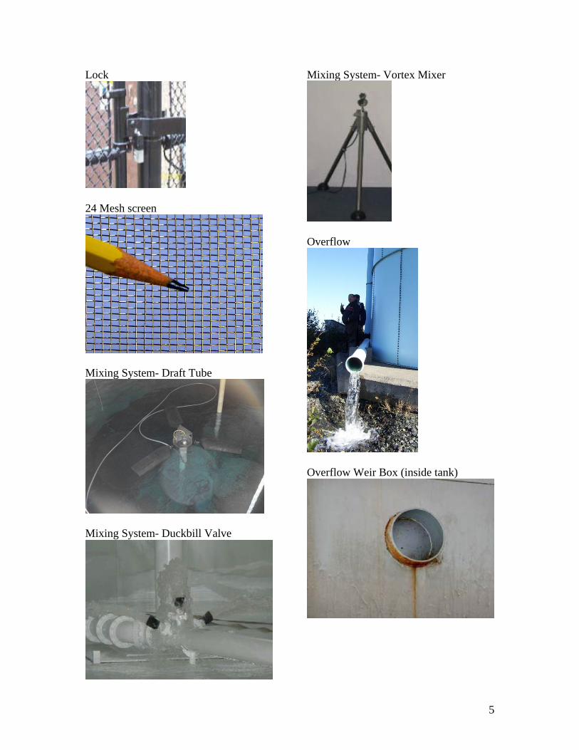
5
Lock
24 Mesh screen
Mixing System- Draft Tube
Mixing System- Duckbill Valve
Mixing System- Vortex Mixer
Overflow
Overflow Weir Box (inside tank)
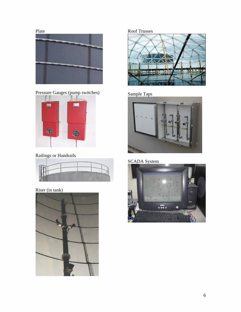
6
Plate
Pressure Gauges (pump switches)
Railings or Handrails
Riser (in tank)
Roof Trusses
Sample Taps
SCADA System

7
Screen (on vent)
Sensor Cables- Water Level (from in-ground tank)
Sight glass
Silt Stop (inside tank)
Spider Rods
Splash Plate

8
Support Column
Telemetry
Valve
Vent
Walkway
Weld
Wind Rods

APPENDIX B: DATABASE OF WATER STORAGE TANKS IN NEWFOUNDLAND
AND LABRADOR
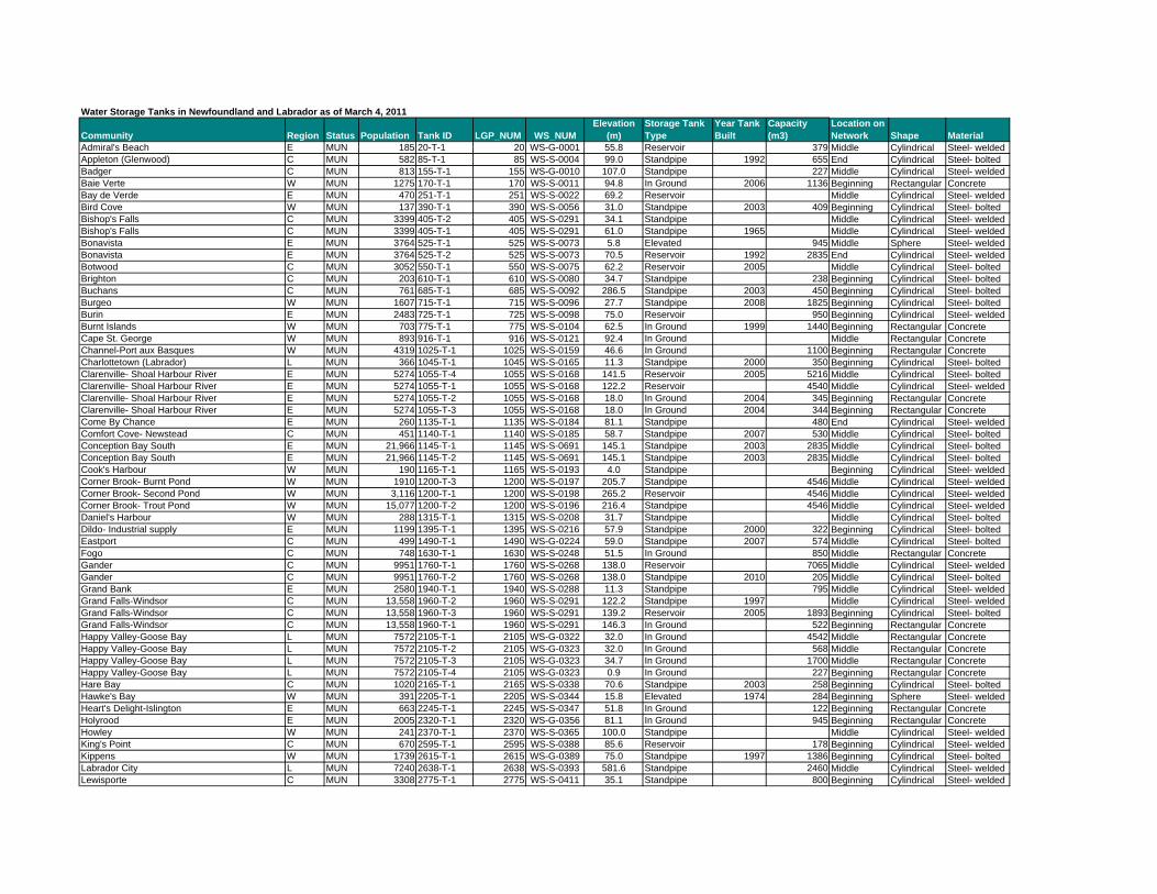
Water Storage Tanks in Newfoundland and Labrador as of March 4, 2011
Community Region Status Population Tank ID LGP_NUM WS_NUMElevation
(m)Storage Tank Type
Year Tank Built
Capacity (m3)
Location on Network Shape Material
Admiral's Beach E MUN 185 20-T-1 20 WS-G-0001 55.8 Reservoir 379 Middle Cylindrical Steel- weldedAppleton (Glenwood) C MUN 582 85-T-1 85 WS-S-0004 99.0 Standpipe 1992 655 End Cylindrical Steel- boltedBadger C MUN 813 155-T-1 155 WS-G-0010 107.0 Standpipe 227 Middle Cylindrical Steel- weldedBaie Verte W MUN 1275 170-T-1 170 WS-S-0011 94.8 In Ground 2006 1136 Beginning Rectangular ConcreteBay de Verde E MUN 470 251-T-1 251 WS-S-0022 69.2 Reservoir Middle Cylindrical Steel- weldedBird Cove W MUN 137 390-T-1 390 WS-S-0056 31.0 Standpipe 2003 409 Beginning Cylindrical Steel- boltedBishop's Falls C MUN 3399 405-T-2 405 WS-S-0291 34.1 Standpipe Middle Cylindrical Steel- weldedBishop's Falls C MUN 3399 405-T-1 405 WS-S-0291 61.0 Standpipe 1965 Middle Cylindrical Steel- weldedBonavista E MUN 3764 525-T-1 525 WS-S-0073 5.8 Elevated 945 Middle Sphere Steel- weldedBonavista E MUN 3764 525-T-2 525 WS-S-0073 70.5 Reservoir 1992 2835 End Cylindrical Steel- weldedBotwood C MUN 3052 550-T-1 550 WS-S-0075 62.2 Reservoir 2005 Middle Cylindrical Steel- boltedBrighton C MUN 203 610-T-1 610 WS-S-0080 34.7 Standpipe 238 Beginning Cylindrical Steel- boltedBuchans C MUN 761 685-T-1 685 WS-S-0092 286.5 Standpipe 2003 450 Beginning Cylindrical Steel- boltedBurgeo W MUN 1607 715-T-1 715 WS-S-0096 27.7 Standpipe 2008 1825 Beginning Cylindrical Steel- boltedBurin E MUN 2483 725-T-1 725 WS-S-0098 75.0 Reservoir 950 Beginning Cylindrical Steel- weldedBurnt Islands W MUN 703 775-T-1 775 WS-S-0104 62.5 In Ground 1999 1440 Beginning Rectangular ConcreteCape St. George W MUN 893 916-T-1 916 WS-S-0121 92.4 In Ground Middle Rectangular ConcreteChannel-Port aux Basques W MUN 4319 1025-T-1 1025 WS-S-0159 46.6 In Ground 1100 Beginning Rectangular ConcreteCharlottetown (Labrador) L MUN 366 1045-T-1 1045 WS-S-0165 11.3 Standpipe 2000 350 Beginning Cylindrical Steel- boltedClarenville- Shoal Harbour River E MUN 5274 1055-T-4 1055 WS-S-0168 141.5 Reservoir 2005 5216 Middle Cylindrical Steel- boltedClarenville- Shoal Harbour River E MUN 5274 1055-T-1 1055 WS-S-0168 122.2 Reservoir 4540 Middle Cylindrical Steel- weldedClarenville- Shoal Harbour River E MUN 5274 1055-T-2 1055 WS-S-0168 18.0 In Ground 2004 345 Beginning Rectangular ConcreteClarenville- Shoal Harbour River E MUN 5274 1055-T-3 1055 WS-S-0168 18.0 In Ground 2004 344 Beginning Rectangular ConcreteCome By Chance E MUN 260 1135-T-1 1135 WS-S-0184 81.1 Standpipe 480 End Cylindrical Steel- weldedComfort Cove- Newstead C MUN 451 1140-T-1 1140 WS-S-0185 58.7 Standpipe 2007 530 Middle Cylindrical Steel- boltedConception Bay South E MUN 21,966 1145-T-1 1145 WS-S-0691 145.1 Standpipe 2003 2835 Middle Cylindrical Steel- boltedConception Bay South E MUN 21,966 1145-T-2 1145 WS-S-0691 145.1 Standpipe 2003 2835 Middle Cylindrical Steel- boltedCook's Harbour W MUN 190 1165-T-1 1165 WS-S-0193 4.0 Standpipe Beginning Cylindrical Steel- weldedCorner Brook- Burnt Pond W MUN 1910 1200-T-3 1200 WS-S-0197 205.7 Standpipe 4546 Middle Cylindrical Steel- weldedCorner Brook- Second Pond W MUN 3,116 1200-T-1 1200 WS-S-0198 265.2 Reservoir 4546 Middle Cylindrical Steel- weldedCorner Brook- Trout Pond W MUN 15,077 1200-T-2 1200 WS-S-0196 216.4 Standpipe 4546 Middle Cylindrical Steel- weldedDaniel's Harbour W MUN 288 1315-T-1 1315 WS-S-0208 31.7 Standpipe Middle Cylindrical Steel- boltedDildo- Industrial supply E MUN 1199 1395-T-1 1395 WS-S-0216 57.9 Standpipe 2000 322 Beginning Cylindrical Steel- boltedEastport C MUN 499 1490-T-1 1490 WS-G-0224 59.0 Standpipe 2007 574 Middle Cylindrical Steel- boltedFogo C MUN 748 1630-T-1 1630 WS-S-0248 51.5 In Ground 850 Middle Rectangular ConcreteGander C MUN 9951 1760-T-1 1760 WS-S-0268 138.0 Reservoir 7065 Middle Cylindrical Steel- weldedGander C MUN 9951 1760-T-2 1760 WS-S-0268 138.0 Standpipe 2010 205 Middle Cylindrical Steel- boltedGrand Bank E MUN 2580 1940-T-1 1940 WS-S-0288 11.3 Standpipe 795 Middle Cylindrical Steel- weldedGrand Falls-Windsor C MUN 13,558 1960-T-2 1960 WS-S-0291 122.2 Standpipe 1997 Middle Cylindrical Steel- weldedGrand Falls-Windsor C MUN 13,558 1960-T-3 1960 WS-S-0291 139.2 Reservoir 2005 1893 Beginning Cylindrical Steel- boltedGrand Falls-Windsor C MUN 13,558 1960-T-1 1960 WS-S-0291 146.3 In Ground 522 Beginning Rectangular ConcreteHappy Valley-Goose Bay L MUN 7572 2105-T-1 2105 WS-G-0322 32.0 In Ground 4542 Middle Rectangular ConcreteHappy Valley-Goose Bay L MUN 7572 2105-T-2 2105 WS-G-0323 32.0 In Ground 568 Middle Rectangular ConcreteHappy Valley-Goose Bay L MUN 7572 2105-T-3 2105 WS-G-0323 34.7 In Ground 1700 Middle Rectangular ConcreteHappy Valley-Goose Bay L MUN 7572 2105-T-4 2105 WS-G-0323 0.9 In Ground 227 Beginning Rectangular ConcreteHare Bay C MUN 1020 2165-T-1 2165 WS-S-0338 70.6 Standpipe 2003 258 Beginning Cylindrical Steel- boltedHawke's Bay W MUN 391 2205-T-1 2205 WS-S-0344 15.8 Elevated 1974 284 Beginning Sphere Steel- weldedHeart's Delight-Islington E MUN 663 2245-T-1 2245 WS-S-0347 51.8 In Ground 122 Beginning Rectangular ConcreteHolyrood E MUN 2005 2320-T-1 2320 WS-G-0356 81.1 In Ground 945 Beginning Rectangular ConcreteHowley W MUN 241 2370-T-1 2370 WS-S-0365 100.0 Standpipe Middle Cylindrical Steel- weldedKing's Point C MUN 670 2595-T-1 2595 WS-S-0388 85.6 Reservoir 178 Beginning Cylindrical Steel- weldedKippens W MUN 1739 2615-T-1 2615 WS-G-0389 75.0 Standpipe 1997 1386 Beginning Cylindrical Steel- boltedLabrador City L MUN 7240 2638-T-1 2638 WS-S-0393 581.6 Standpipe 2460 Middle Cylindrical Steel- weldedLewisporte C MUN 3308 2775-T-1 2775 WS-S-0411 35.1 Standpipe 800 Beginning Cylindrical Steel- welded
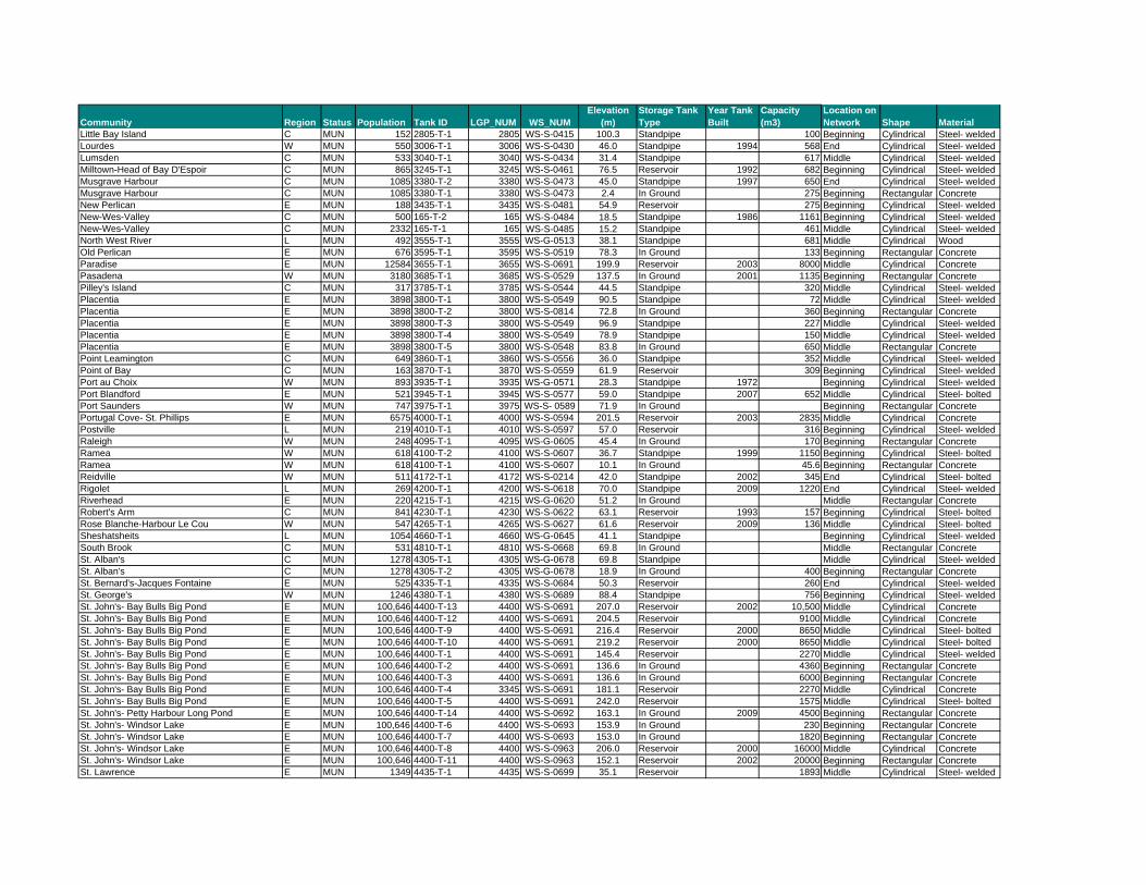
Community Region Status Population Tank ID LGP_NUM WS_NUMElevation
(m)Storage Tank Type
Year Tank Built
Capacity (m3)
Location on Network Shape Material
Little Bay Island C MUN 152 2805-T-1 2805 WS-S-0415 100.3 Standpipe 100 Beginning Cylindrical Steel- weldedLourdes W MUN 550 3006-T-1 3006 WS-S-0430 46.0 Standpipe 1994 568 End Cylindrical Steel- weldedLumsden C MUN 533 3040-T-1 3040 WS-S-0434 31.4 Standpipe 617 Middle Cylindrical Steel- weldedMilltown-Head of Bay D'Espoir C MUN 865 3245-T-1 3245 WS-S-0461 76.5 Reservoir 1992 682 Beginning Cylindrical Steel- weldedMusgrave Harbour C MUN 1085 3380-T-2 3380 WS-S-0473 45.0 Standpipe 1997 650 End Cylindrical Steel- weldedMusgrave Harbour C MUN 1085 3380-T-1 3380 WS-S-0473 2.4 In Ground 275 Beginning Rectangular ConcreteNew Perlican E MUN 188 3435-T-1 3435 WS-S-0481 54.9 Reservoir 275 Beginning Cylindrical Steel- weldedNew-Wes-Valley C MUN 500 165-T-2 165 WS-S-0484 18.5 Standpipe 1986 1161 Beginning Cylindrical Steel- weldedNew-Wes-Valley C MUN 2332 165-T-1 165 WS-S-0485 15.2 Standpipe 461 Middle Cylindrical Steel- weldedNorth West River L MUN 492 3555-T-1 3555 WS-G-0513 38.1 Standpipe 681 Middle Cylindrical WoodOld Perlican E MUN 676 3595-T-1 3595 WS-S-0519 78.3 In Ground 133 Beginning Rectangular ConcreteParadise E MUN 12584 3655-T-1 3655 WS-S-0691 199.9 Reservoir 2003 8000 Middle Cylindrical ConcretePasadena W MUN 3180 3685-T-1 3685 WS-S-0529 137.5 In Ground 2001 1135 Beginning Rectangular ConcretePilley's Island C MUN 317 3785-T-1 3785 WS-S-0544 44.5 Standpipe 320 Middle Cylindrical Steel- weldedPlacentia E MUN 3898 3800-T-1 3800 WS-S-0549 90.5 Standpipe 72 Middle Cylindrical Steel- weldedPlacentia E MUN 3898 3800-T-2 3800 WS-S-0814 72.8 In Ground 360 Beginning Rectangular ConcretePlacentia E MUN 3898 3800-T-3 3800 WS-S-0549 96.9 Standpipe 227 Middle Cylindrical Steel- weldedPlacentia E MUN 3898 3800-T-4 3800 WS-S-0549 78.9 Standpipe 150 Middle Cylindrical Steel- weldedPlacentia E MUN 3898 3800-T-5 3800 WS-S-0548 83.8 In Ground 650 Middle Rectangular ConcretePoint Leamington C MUN 649 3860-T-1 3860 WS-S-0556 36.0 Standpipe 352 Middle Cylindrical Steel- weldedPoint of Bay C MUN 163 3870-T-1 3870 WS-S-0559 61.9 Reservoir 309 Beginning Cylindrical Steel- weldedPort au Choix W MUN 893 3935-T-1 3935 WS-G-0571 28.3 Standpipe 1972 Beginning Cylindrical Steel- weldedPort Blandford E MUN 521 3945-T-1 3945 WS-S-0577 59.0 Standpipe 2007 652 Middle Cylindrical Steel- boltedPort Saunders W MUN 747 3975-T-1 3975 WS-S- 0589 71.9 In Ground Beginning Rectangular ConcretePortugal Cove- St. Phillips E MUN 6575 4000-T-1 4000 WS-S-0594 201.5 Reservoir 2003 2835 Middle Cylindrical ConcretePostville L MUN 219 4010-T-1 4010 WS-S-0597 57.0 Reservoir 316 Beginning Cylindrical Steel- weldedRaleigh W MUN 248 4095-T-1 4095 WS-G-0605 45.4 In Ground 170 Beginning Rectangular ConcreteRamea W MUN 618 4100-T-2 4100 WS-S-0607 36.7 Standpipe 1999 1150 Beginning Cylindrical Steel- boltedRamea W MUN 618 4100-T-1 4100 WS-S-0607 10.1 In Ground 45.6 Beginning Rectangular ConcreteReidville W MUN 511 4172-T-1 4172 WS-S-0214 42.0 Standpipe 2002 345 End Cylindrical Steel- boltedRigolet L MUN 269 4200-T-1 4200 WS-S-0618 70.0 Standpipe 2009 1220 End Cylindrical Steel- weldedRiverhead E MUN 220 4215-T-1 4215 WS-G-0620 51.2 In Ground Middle Rectangular ConcreteRobert's Arm C MUN 841 4230-T-1 4230 WS-S-0622 63.1 Reservoir 1993 157 Beginning Cylindrical Steel- boltedRose Blanche-Harbour Le Cou W MUN 547 4265-T-1 4265 WS-S-0627 61.6 Reservoir 2009 136 Middle Cylindrical Steel- boltedSheshatsheits L MUN 1054 4660-T-1 4660 WS-G-0645 41.1 Standpipe Beginning Cylindrical Steel- weldedSouth Brook C MUN 531 4810-T-1 4810 WS-S-0668 69.8 In Ground Middle Rectangular ConcreteSt. Alban's C MUN 1278 4305-T-1 4305 WS-G-0678 69.8 Standpipe Middle Cylindrical Steel- weldedSt. Alban's C MUN 1278 4305-T-2 4305 WS-G-0678 18.9 In Ground 400 Beginning Rectangular ConcreteSt. Bernard's-Jacques Fontaine E MUN 525 4335-T-1 4335 WS-S-0684 50.3 Reservoir 260 End Cylindrical Steel- weldedSt. George's W MUN 1246 4380-T-1 4380 WS-S-0689 88.4 Standpipe 756 Beginning Cylindrical Steel- weldedSt. John's- Bay Bulls Big Pond E MUN 100,646 4400-T-13 4400 WS-S-0691 207.0 Reservoir 2002 10,500 Middle Cylindrical ConcreteSt. John's- Bay Bulls Big Pond E MUN 100,646 4400-T-12 4400 WS-S-0691 204.5 Reservoir 9100 Middle Cylindrical ConcreteSt. John's- Bay Bulls Big Pond E MUN 100,646 4400-T-9 4400 WS-S-0691 216.4 Reservoir 2000 8650 Middle Cylindrical Steel- boltedSt. John's- Bay Bulls Big Pond E MUN 100,646 4400-T-10 4400 WS-S-0691 219.2 Reservoir 2000 8650 Middle Cylindrical Steel- boltedSt. John's- Bay Bulls Big Pond E MUN 100,646 4400-T-1 4400 WS-S-0691 145.4 Reservoir 2270 Middle Cylindrical Steel- weldedSt. John's- Bay Bulls Big Pond E MUN 100,646 4400-T-2 4400 WS-S-0691 136.6 In Ground 4360 Beginning Rectangular ConcreteSt. John's- Bay Bulls Big Pond E MUN 100,646 4400-T-3 4400 WS-S-0691 136.6 In Ground 6000 Beginning Rectangular ConcreteSt. John's- Bay Bulls Big Pond E MUN 100,646 4400-T-4 3345 WS-S-0691 181.1 Reservoir 2270 Middle Cylindrical ConcreteSt. John's- Bay Bulls Big Pond E MUN 100,646 4400-T-5 4400 WS-S-0691 242.0 Reservoir 1575 Middle Cylindrical Steel- boltedSt. John's- Petty Harbour Long Pond E MUN 100,646 4400-T-14 4400 WS-S-0692 163.1 In Ground 2009 4500 Beginning Rectangular ConcreteSt. John's- Windsor Lake E MUN 100,646 4400-T-6 4400 WS-S-0693 153.9 In Ground 230 Beginning Rectangular ConcreteSt. John's- Windsor Lake E MUN 100,646 4400-T-7 4400 WS-S-0693 153.0 In Ground 1820 Beginning Rectangular ConcreteSt. John's- Windsor Lake E MUN 100,646 4400-T-8 4400 WS-S-0963 206.0 Reservoir 2000 16000 Middle Cylindrical ConcreteSt. John's- Windsor Lake E MUN 100,646 4400-T-11 4400 WS-S-0963 152.1 Reservoir 2002 20000 Beginning Rectangular ConcreteSt. Lawrence E MUN 1349 4435-T-1 4435 WS-S-0699 35.1 Reservoir 1893 Middle Cylindrical Steel- welded

Community Region Status Population Tank ID LGP_NUM WS_NUMElevation
(m)Storage Tank Type
Year Tank Built
Capacity (m3)
Location on Network Shape Material
St. Lunaire-Griquet W MUN 666 2050-T-1 2050 WS-S-0701 36.3 In Ground 180 Middle Rectangular ConcreteSt. Mary's E MUN 482 4455-T-1 4455 WS-S-0703 83.8 Reservoir 1988 415 Beginning Cylindrical Steel- weldedSt. Pauls W MUN 309 4475-T-1 4475 WS-S-0707 50.0 In Ground 418 Beginning Rectangular ConcreteStephenville W MUN 6588 4945-T-1 4945 WS-G-0716 82.0 Reservoir 2000 4760 Beginning Cylindrical Steel- boltedStephenville W MUN 6588 4945-T-2 4945 WS-G-0716 82.0 Reservoir 2000 4760 Beginning Cylindrical Steel- boltedStephenvillle Crossing W MUN 1960 4950-T-1 4950 WS-G-0717 11.6 Standpipe 2000 1591 Middle Cylindrical Steel- boltedTrepassey E MUN 763 5145-T-1 5145 WS-S-0743 28.7 Standpipe 750 Middle Cylindrical Steel- weldedTriton C MUN 1029 5170-T-1 5170 WS-S-0748 15.2 Standpipe 225 Beginning Cylindrical Steel- weldedTrout River W MUN 604 5175-T-1 5175 WS-S-0750 45.7 Standpipe 627 Beginning Cylindrical Steel- boltedTwillingate C MUN 2448 5195-T-1 5195 WS-S-0754 44.3 Standpipe 1125 Beginning Cylindrical Steel- weldedWabana E MUN 2418 5245-T-1 5245 WS-G-0763 102.1 Standpipe 2009 1134 Middle Cylindrical Steel- boltedWabush L MUN 1739 5249-T-1 5249 WS-S-0775 582.8 Standpipe 2200 Middle Cylindrical Steel- welded
Whitbourne E MUN 855 5355-T-1 5355 WS-S-0779 84.1 Elevated 900 Middle CylindricalSteel-welded/ concrete
Winterland E MUN 337 5445-T-1 5445 WS-G-0786 46.9 Standpipe 2000 286 Beginning Cylindrical Steel- boltedWoody Point W MUN 355 5490-T-1 5490 WS-S-0792 46.3 Standpipe 1976 1357 Middle Cylindrical Steel- welded

APPENDIX C: REVISED DESIGN GUIDELINES FOR WATER STORAGE TANKS

1
1.1 Potable Water Storage
This section addresses the requirements for treated water storage in drinking water supply systems. A properly designed and maintained water storage facility may achieve an expected service life of between 25-100 years depending on the tank material. Finished water storage facilities should be designed to equalize water demands, maintain adequate pressures in the distribution system, and to meet critical water demands during fire flow and emergency conditions. In the design and operation of water storage facilities, consideration should also be given to minimizing chemical, biological and physical water quality issues. 1.1.1 Definitions
Above Ground Storage – A water storage structure that is primarily above ground such as a standpipe, reservoir or elevated tank. See Figure 1. Elevated Tank – Elevated tanks generally consist of a water tank supported by a steel or concrete tower that does not form part of the storage volume. In general, an elevated tank supplies peak balancing flows. See Figure 1. Standpipe – A standpipe is a tank that is located on the ground surface and has a greater height than diameter. In most installations water in the upper portion of the tank is used for peak flow balancing (equalization), the remaining volume is for fire flow and emergency storage. See Figure 1. Reservoir – A treated water reservoir is a storage facility located on the ground surface where the width/diameter is typically greater than the height and usually applies to large storage facilities. See Figure 1. In-Ground Reservoir – An in-ground reservoir is a water storage structure that is partially below the nominal surface of the ground. A typical construction has the reservoir located 50% above and 50% below ground. See Figure 2.
Figure 1: Above Ground Storage

2
Figure 2: In-ground Reservoir
1.1.2 Location of Distribution Storage
The following factors must be considered in choosing a location for distribution system storage:
The relationship between distribution system hydraulics (including topography) and water demands in various parts of the system.
Pumping and transmission costs as location of the storage facilities at natural high points allows for gravitational flow and potential cost savings.
Availability of appropriate land and public acceptance of the structure. Site access and safety considerations including proximity to airports, power lines,
obstructions, etc. Future expansion. Drainage at the site. Geotechnical conditions derived from test pit results including location of the
groundwater table, soil bearing capacity, and seismic zone. Wind conditions. Maintaining water quality such that overall water age is kept to a minimum.
Storage facilities should ideally be located on the highest point of ground in the area. For larger distribution systems, the placement of one storage tank at a central location should be evaluated against smaller units with equivalent total volume in other parts of the system. The designer should be aware that flow reversals may create sediment uptake and dispersal, as well as loss of disinfectant residual. This may be a more significant issue where the storage tank is located at an extremity of the distribution system. The following are considered minimum requirements:
1. Any opening in the storage facility including overflows, vents, access hatches (including the top of in-ground reservoirs), must not be less than 600 mm above normal ground surface or the level of the 100 year flood (or the highest flood of record).

3
2. The bottom of above ground reservoirs and standpipes must be placed at the normal ground surface and must be at a level above the 100-year flood (or the highest flood of record). Tank access roads must be at a level above the 100-year flood (or the highest flood of record).
3. When the bottom of the storage reservoir must be below normal ground surface,
the in-ground reservoir must be placed above the groundwater table. Typically at least 50% of the water depth should be above grade.
4. Sewers, drains, septic tanks and tile fields, standing water and similar potential
sources of contamination must be kept at least 15 m away from the storage facility.
Where pipelines are located underneath or close to a storage facility, the use of rigid pipe or pipe with adequate joint flexibility is recommended to minimize potential damage due to differential settling or movement of the storage facility. 1.1.3 Design Considerations
The top water level and location of the storage structures will be determined by the hydraulic analysis undertaken for the design of the distribution system to result in acceptable service pressures throughout the existing and future service areas. The materials and design used for treated water storage structures should provide stability and durability as well as protect the quality of the stored water. The following subsections outline criteria to be considered when designing treated water storage facilities. 1.1.3.1 Pressure Considerations The minimum required water level for a distribution system storage facility must provide acceptable service pressures throughout the distribution system as outlined in Section 3.7.3.3. Storage facilities must be designed to maintain adequate pressure in the distribution system at the average day water demand in the event of a power failure or other emergency. 1.1.3.2 Detention Time The time that water stays in storage after disinfectants are added, but before the water is delivered to the first customer, can be counted towards the disinfectant contact time. Theoretical average residence time in the tank can be calculated using the following equation: Where N, or the number of fill/draw cycles per day can be determined using the following equation:
NVV
VHRT
1
minmax
max

4
Supplemental chlorination may be required to maintain minimum chlorine residuals in water from water storage facilities that have insufficient residual chlorine or insufficient turnover of water. A detailed design of the inlet, outlet and baffling is required where storage facilities are used as supplemental chlorination stations. A bulk water disinfectant decay test that indicated disinfectant residual as a function of time can be conducted to determine desirable hydraulic retention time in the water storage tank. 1.1.3.3 System Modeling Where appropriate, hydraulic, water quality and computational fluid dynamics models should be used in the design of storage facilities. Such tools can be used to optimize tank location, sizing, operation, mixing, and disinfectant dosing. 1.1.4 Sizing of Water Storage Facilities
Storage facilities should have sufficient capacity, as determined from engineering studies, to meet the required domestic demands, and where fire protection is provided, fire flow demands. Emergency storage volumes should be provided to supply demands in the event of pipeline or equipment breakdowns or maintenance shutdowns. Excessive storage capacity should be avoided where water quality deterioration may occur. Potable water storage tanks are typically over 38 m3 in volume. Any volume required to provide chemical disinfection contact time is not available for storage and should not be included in storage calculations. Refer to Section 4.2 for more information on primary disinfection with chlorine and contact time. Treated water storage volumes should be calculated using a projected design population of no more than 10 years in cases of projected population growth. In cases of projected population decline, the current population should be used in the design of required storage volumes. The total water storage requirements for a given water supply system where the treatment plant is capable of satisfying only the maximum day demand may be calculated using the following equation:
S = A + B + C Where: S = Total Storage requirement, m3; A = Fire Storage, m3 (equal to required fire flow over required duration); B = Peak Balanced Storage, m3 (25% of maximum day demand); and C = Emergency Storage, m3 (25% of A + B).
cycledrawfillforTimeN
/
24

5
Notes: 1. The above equation is for the calculation of the storage requirement for a system
where the water treatment plant is capable of satisfying only the maximum day demand. For situations where the water treatment plant can supply more, the above storage requirements can be reduced accordingly.
2. The maximum day demand referred to in the above equation should be calculated
using existing flow data whenever possible, otherwise the factors in Table 3.7 may be used where: Maximum Day Demand = Average Day Demand x Maximum Day Factor. Where existing data is available, the required storage should be calculated on the basis of the demand characteristics within the system.
3. Should the proponent have decided to provide a potable water supply and
distribution system not capable of providing fire protection, the usable volume of storage to be provided should be 25% of design year maximum day plus 40% of the design year average day.
4. The designer is expected to recognize that this formula for calculating treated
water storage requirements must be supplemental with the plant water storage required for the operation of the water treatment facility (i.e. backwash and domestic use).
5. For distribution systems serving communities of 500 people or less with no fire
protection, the minimum effective storage to be provided must be the average daily flow. Where fire protection is to be provided, the minimum volume of the storage facility must be increased by an amount equal to the minimum fire flow for two hours (1000 L/min for 2 hours).
1.1.4.1 Fire Flow Storage Requirements Fire demand may not occur very often, however, when it does occur, the rate of water use is usually much greater than for domestic peak demand. Also, the required fire storage volume can account for as much as 50% of total capacity of the reservoirs. Fire storage comprises a portion of the inactive volume of water in a tank. The level of fire protection is the responsibility of the municipality. Fire flow requirements are typically established by the municipality’s insurance company or the Fire Underwriters Survey. For fire flow requirements, refer to the latest edition of the Fire Underwriters Survey document Water Supply for Public Fire Protection1. The level of storage may be further reduced if the water treatment plant is capable of supplying portions of the required fire-flow volumes. The fire (A) and emergency (C) component volumes should be located between the elevation necessary to produce 275 kPa (40 psi) under peak hourly flow conditions and
1 Fire Underwriters Survey is a national organization administered by SCM Risk Management Services Inc., 238 Brownlow Ave., Suite 300, Dartmouth, NL, B3B 1Y2, 1-800-639-4528, in Atlantic Canada.

6
the elevation necessary to produce a minimum 140 kPa (20 psi) under the maximum day plus fire flow conditions. 1.1.4.2 Peak Balancing Storage Requirements Peak balancing storage, also known as operational storage, is directly related to the amount of water necessary to meet peak demands. Equalization storage comprises the active volume of water stored in the tank. The intent of peak balancing storage is to make up the difference between the consumer’s peak demands and the system’s available supply. With peak balancing storage, system pressures are typically improved and stabilized. The value of the peak balancing storage is a function of the diurnal demand fluctuation in a community and is commonly estimated at 25% of the total maximum day demand. The equalization volume (B) in the storage facility should be located between the top water level (TWL) of the storage facility and the elevation necessary to produce a minimum pressure of 275 kPa (40 psi) in the majority of the system under peak hourly flow. 1.1.4.3 Emergency Storage During periods of power failure, mechanical or pipeline breakdown or maintenance when use of source water is prevented, there is a need for emergency storage. Emergency storage comprises a portion of the inactive volume of water in a tank. This is the volume of water recommended to meet the demand during maintenance shut-downs or emergency situations, such as source supply failures, watermain failures, electrical power outages, or natural disasters. The amount of emergency storage included with a particular water system is not set, but is typically based on an assessment of risk and desired degree of system dependability. In considering emergency storage, it is acceptable to evaluate providing significantly reduced supplies during emergencies. In the absence of clear information, 15% of projected average daily design flow can be used, or 25% of (Peak Balancing + Fire Flow). 1.1.4.4 Dead Storage If a storage structure is of a type where only the upper portion of the water provides a useful function, such as maintaining usable system pressure, the remaining lower portion is considered dead storage. Dead storage can be considered useful if pumps can withdraw the water from the lower portion of the storage structure during a fire or other emergency. Where dead storage is present there must be adequate measures taken to circulate the water through the tank to maintain quality and prevent freezing (i.e. baffles, filling/emptying techniques, and adequate mixing provisions). Unusable dead storage should be avoided wherever possible.

7
1.1.5 Construction Materials
Storage facilities, including pipes, fittings and valves, must conform to the latest standards issued by the CSA or AWWA. Standards for typical steel and concrete water storage tanks, standpipes, reservoirs, and elevated tanks acceptable to ENVC include:
AWWA Standard D110: Wire- and Strand-Wound, Circular, Prestressed Concrete Water Tanks
AWWA Standard D115: Tendon-Prestressed Concrete Water Tank AWWA Standard D100: Welded Carbon Steel Tanks for Water Storage AWWA Standard D103: Factory-Coated Bolted Carbon Steel Tanks for Water
Storage AWWA Standard D120: Thermosetting Fiberglass Reinforced Plastic Tanks AWWA Standard D108: Aluminum Dome Roofs for Water Storage Facilities
In the absence of such standards, materials meeting applicable Product Standards and acceptable to the ENVC may be selected. Special attention should be given to selecting pipe materials that will protect against internal and external pipe corrosion. All products must comply with CSA/ANSI standards. Any material that comes in contact with drinking water must comply with NSF Standard 61. Other materials of construction may be acceptable when properly designed to meet the requirements of treated water storage. 1.1.6 Maintaining Water Quality
Deterioration in water quality is frequently associated with excessive retention time and aging water. Loss of disinfection residual, formation of DBPs, and bacterial re-growth can all result from aging of water. As a result, an implicit objective in both design and operation of distribution system storage facilities is to minimize detention times and prevent stagnation. The allowable detention time should depend on the quality of the water, its reactivity, the type of disinfectant used and the travel time before and after the water’s entry into the storage facility. A maximum 72-hour residence time is recommended. The volume of water turnover in the tank during a fill/draw cycle is another key component in evaluating the effectiveness of tank mixing. A minimum turnover of 20% of storage volume per fill/draw cycle is recommended. Passive or active mixing systems can reduce actual detention times and prevent stagnation in the tank. Such systems include separation of the inlet and outlet, location and orientation of the inlet and outlet, baffle walls, mechanical mixing devices, adjusting the pump schedule for deep cycling, re-circulation pumps, jet creation at the inlet, and changing operational water levels in the tank. A tank mixing system must be considered in the following situations:
There is excessive chlorine consumption in the distribution system with loss of residual towards the end of the system.
There are elevated DBP levels in the distribution system.

8
The tank is a standpipe. The tank is located at the end of the distribution system. There is high seasonal demand on the distribution system. The distribution system is under utilized or there is unrealized growth on the
system. The tank is below the hydraulic grade. The tank receives mixed source waters.
Commercial mixing systems should be validated to demonstrate complete mixing of the water storage facility. 1.1.7 Storage Facility Requirements
1.1.7.1 Inlet/Outlet A detailed design of the inlet and outlet is required to ensure maximum turnover of water in a storage tank. Consideration should be given to the orientation of the inlet and whether it is horizontal, vertical or angled. Consideration should also be given to the path of the inflow jet and whether it is towards the maximum length of water in the tank, tangential to the side wall, or towards the minimum length of water in the tank or an obstruction. Inflow into the tank should be turbulent. Tank mixing may be addressed by the configuration of the inlet and outlet in the storage facility. Separation of the inlet and outlet and varying the height of the inlet from the outlet should be considered. 1.1.7.2 Multi-Cell Provision or Adjacent Compartments In-ground storage reservoirs should be constructed with two cells which can be operated independently. Through valving it should be possible to isolate one of the two cells without affecting the operation of the other cell. Cells should be of sufficient volume to store an adequate volume of water for the duration of the maintenance. Flexibility should be built in to operate the cells in series or parallel, or pump from either cell. The wall must be designed to withstand all forces that an external wall would experience. When planning the type of reservoir, the designer shall ensure that treated water is not stored or conveyed in a compartment adjacent to untreated water if the two compartments are separated by a single wall. 1.1.7.3 Instrumentation and Level Control Adequate instrumentation to control water levels in storage facilities must be provided in order to maintain system pressures and avoid tank overflows. Instrumentation must be provided to monitor water level in the tank. Instrumentation may also be provided to record the water level in the tank. Flow rate in and out of the tank, and chlorine residuals in the tank may also be monitored. Water level in tanks may be monitored and controlled by telemetry or SCADA systems, especially if water levels in the tank control the operation of pumps. Water level sensors can include contact sensors (bubblers, radio frequency admittance, tuning fork, floats,

9
conductivity switch, magnetic switch, torsion switch) and non-contact sensors (ultrasonic, radar, pressure transmitters). Icing is a concern with most level sensing technologies. Water level in tanks may also be controlled by altitude valves which function automatically to regulate the flow of fluid into and out of the tank. Altitude valves can be used with pumped or gravity flow systems, however, they do not allow for water level monitoring. There must be capability to isolate and bypass the altitude valve, if present. Freezing of sensing lines may give the altitude valve false signals and cause the tank to operate improperly. Electrical heat tape and insulation on the control piping or heating the altitude valve enclosure minimizes these problems. SCADA systems should transmit data from water level sensors to a central location. Pump operation may be controlled from tank water level sensor data that is transmitted by telemetry equipment to the SCADA master station. Overflow and low-level warnings or alarms should be located where they will be under responsible surveillance 24 hours a day. Where access to the top of the reservoir is convenient (such as in-ground tank) an ultrasonic level transmitter should be used. Where access to the bottom of the reservoir is convenient (such as at a tower or above-ground reservoir), a pressure transmitter should be used as a level-sensing device. See Section 6.1.5.1 for more details. Changes in water level in a storage tank during daily domestic water demands must be limited to a maximum 9 m to stabilize pressure fluctuations within the distribution system. 1.1.7.4 Overflow All above ground water storage structures must be provided with an overflow, which is brought to an elevation at least 600 mm above the ground surface, and discharges over a drainage inlet structure or a splash plate which drains away from the storage facility. When an internal overflow pipe is used on elevation tanks, it should be located in the access tube. For vertical drops on other types of storage facilities, the overflow pipe should be located on the outside of the structure. The overflow pipe on in-ground tanks must terminate 600 mm above ground level or above the 100-year flood level (or the highest flood of record). An overflow must not be connected directly to a sewer or storm drain. All overflow pipes must be located so that any discharge is visible. Alarms should be installed to alert the operator of an overflow event. Overflows must be screened to prevent the entrance of birds, animals and insects. Overflows must open downward and be fitted with 24-mesh non-corrodible screen. The screen should be installed within the overflow pipe at a location least susceptible to damage by vandalism. If a flapper or check valve is used, the screen should be installed upstream of the valve. The screen should be located such that it can easily be replaced following an overflow event. A backflow preventer should be installed on all overflows, on in-ground or low-elevation reservoirs.

10
The overflow pipe should be of sufficient diameter to permit the wasting of water in excess of the filling rate. Consideration should be given to downgrade receiving areas of overflow water. The discharge must not be directed to natural water bodies. Discharge in residential areas should be contained to appropriate and controlled storm water channels. 1.1.7.5 Isolation and Drainage of Storage Structures Water storage structures, which provide pressure directly to the distribution system, must be designed so they can be isolated from the distribution system and drained for cleaning or maintenance without necessitating loss of pressure in the distribution system. Consideration should be given to the installation of air release/vacuum relief valves on the distribution side of the isolation valve(s). The tank should have bypass piping to permit operation of the system while the tank is off line. The drain must discharge to the ground surface with no direct connection to a sewer or municipal storm drain, and should be located at least 300 mm above ground surface. The drain in the tank must be recessed or flush with the bottom of the tank with floors sloped towards the sump to facilitate cleaning. The drain line should discharge over a drainage inlet structure or a splash plate which drains away from the storage facility. Foundation drains for in-ground tanks should discharge freely at grade. Water that is drained from storage structures should be dechlorinated prior to discharge to the environment. Hydrants, cleanouts or similar flushing devices may be provided on the piping of the water storage tank. These devices must be located so that they can drain the storage facility when it is isolated from the system. 1.1.7.6 Roof and Sidewall The roof and sidewall of all structures must be watertight with no opening except properly constructed vents, access hatches, overflows, risers, drains, pump and valve mountings, control ports, sampling ports or piping for inflow and outflow. Any pipes running through the roof or sidewall of a metal water storage structure should be welded, or properly gasketed. In concrete tanks, these pipes should be connected to standard wall castings, which were poured in place during the forming of the concrete or pipes should be sealed using rubber link type seals. These wall castings should have water stop flanges or seepage rings imbedded in the concrete. Any openings in a roof or top of a storage facility, designed to accommodate control apparatus or pump columns, must be curbed (100 mm to 150 mm) and sleeved with proper additional shielding to prevent precipitation and contamination from surface water or floor drainage from getting into the structure. Valves and controls should be located outside the storage structure so that the valve stems and similar projections will not pass through the roof or top of the reservoir.

11
The roof of the storage structure must be well drained and not allow any standing water. Downspout pipes should not enter or pass through the reservoir. If the design includes parapets or similar construction which tend to hold water and snow on the roof, drainage should be provided. The roof of concrete reservoirs with earthen cover should be sloped to facilitate drainage. Consideration should be given to the installation of an impermeable membrane roof covering. For elevated tanks and standpipes, the use of heat trace cables on the roof may be necessary to prevent the build up of ice. The installation of additional equipment, such as antennae or cables, must not affect coatings, interfere with the routine operation and maintenance of the tank, or compromise water quality. The sidewall of the tank may be fitted with a sight glass for internal visual inspection of the tank from the outside. 1.1.7.7 Vents Finished water storage structures must be vented to prevent storage facilities from collapsing when water is draining. Overflows are not to be considered as vents. Vents must:
1. Allow air into the tank at a rate greater than the rate at which water is withdrawn in order to avoid the development of vacuum/pressure within the tank;
2. Be turned downward to prevent the entrance of surface water and rainwater; 3. Prevent birds, animals, direct sunlight and air drafts from entering the tank; 4. Be constructed to prevent frosting of the screens or provided with vacuum valves
or failsafe devices;
5. Be located away from areas which will be subject to severe snow drifting;
6. Provide some level of security against accidental or intentional contamination; 7. Exclude insects and dust, as much as this function can be made compatible with
effective venting. For elevated tanks and standpipes, 24-mesh non-corrodible screen may be used; and
8. On in-ground structures, terminate in an inverted U construction with the opening
600 mm to 900 mm above the roof or sod or at a level above the 100-year flood (or the highest flood of record). The vent should be covered with 24-mesh non-corrodible screen. Where a valve house or pump house is provided, the vents should be located within the structure.

12
Large tanks (greater than 1900 m3) should be provided with more than one vent. One should be installed near the centre of the roof, and the other(s) closer to the tank walls to facilitate cross-flow ventilation through the tank. 1.1.7.8 Protection Against Freezing Tanks in areas where the lowest one-day mean temperature is less than -15ºC are likely to experience tank-freezing conditions. Other factors may also contribute to tank freezing such as malfunctioning controls for valves or pumps, a drop in demand in winter, and tanks where the water level is kept static. All finished water storage structures and their appurtenances, especially the riser pipes, overflows, and vents, must be designed to prevent freezing, which may interfere with proper functioning. Freezing may result in rising water levels and bursting of the tank, frozen vents, scraping of interior coatings, damage to structural elements (ladders, overflow weirs, piping), holes and protrusions, and collapse of the reservoir by vacuum action. Alternatives to be considered to avoid freezing include insulation, variable water level operation, internal heating via heat tracing cables, hot water re-circulation, or other passive or active mixing systems discussed in Section 1.1.6. Equipment used for freeze protection that will come into contact with potable water shall meet ANSI/NSF Standard 61 or be approved by ENVC. 1.1.7.9 Silt Stop The discharge pipes from water storage facilities should be located in a manner that will prevent the flow of sediment into the distribution system. Removable silt stops must be provided. A removable silt stop shall be at least 100 mm high, and the fitting or piping connection shall be flush with the tank floor when the stop is removed. 1.1.7.10 Grading The grading around ground-level facilities must direct water away from the tank and prevent standing surface water within 15 m of the tank. 1.1.7.11 Safety The safety of employees must be considered in the design of the storage structure. As a minimum, the design must conform to applicable laws and regulations of the Province (see Section 8). The provincial Occupational Health and Safety Act (O.C . 2009-233) and the Occupational Health and Safety Regulations, 2009 address work safety issues related to water storage tanks including confined space entry, fall protection, ladders, guardrails, removing lead paint from tanks, repainting, and applying coatings, among others. Ladders, ladder guards, railings, handholds and entrance hatches must be provided where applicable. Railings or handholds must be provided on elevated tanks where persons

13
must transfer from the access tube to the water compartment. The design must incorporate easily accessible fall arrest systems for use by operators or emergency response workers for access to the exterior and interior of the structure. If an above ground tank is within an approach pattern to an airport runway, the tank must be equipped with aviation lighting or painted in a special aviation warning paint scheme such as a red-and-white checked pattern. Requirements for obstructions can be found in the Canadian Aviation Regulations. System operators must monitor any warning light’s operation and replace the light when it burns out. The installation of additional equipment on the tank, such as communication antennae, attachments, power conduits and cables, must not interfere with access to the tank, including obstructing ladders and access hatches or preventing the safe use of ladder safety devices. Additional equipment must not interfere with operation and maintenance of the tank, puncture the tank, affect internal coatings or compromise water quality. All cables and wires to devices on the storage tank must be installed inside properly constructed conduits. Properly designed brackets must safely secure the conduits to the storage structure. ENVC should be notified of any such installations which must be designed and constructed to pertinent industry standards. Large diameter wet risers in the bottom of elevated tanks must be installed with guardrails to protect people from falling into the riser. Grates over the riser tops are not adequate as they are easily damaged and displaced by ice. If the wet riser extends into the tank for this purpose, it must meet the same criteria as a guard rail system. 1.1.7.12 Access and Security Access to water storage structures must be restricted to authorized people only. Only trained and experienced workers are allowed to work in or on water storage facilities. Finished water storage structures must be designed with convenient and safe access to the interior for sample collection, cleaning and maintenance. An access manhole must be a minimum of 600 mm in diameter. All water storage structures should have at least two access ways such that when ventilation equipment blocks one, the other is free from obstruction. For in-ground tanks, at least two manholes should be provided above the waterline at each water compartment where space permits. A minimum of two opposing manholes are required on welded ground-supported tanks. Access manholes in above ground structures should be framed at least 100 mm above the surface of the roof or tank wall at the opening. It should be fitted with a solid watertight cover which overlaps the framed opening and extends down around the frame at least 50 mm, be hinged on one side, and have a locking device. All other access ways should be bolted and gasketed. For below ground structures, each access hatch frame should be elevated a minimum 600 mm above the top of the tank or groundcover and should be fitted with a solid, watertight cover which overlaps a framed opening and extends down around the frame at least 50

14
mm. Alternatively, the cover should have an integral perimeter trough and drain. Each cover should be hinged on one side using non-removable hinges and should have a locking device. On above ground tanks, exterior ladders must terminate at least 2.4 m above ground and have their bottom sections covered with locking ladder guards. Storage facilities should consider perimeter fencing with a secure lock. If necessary, the fence could be topped with barbed or razor wire. All access hatches, vault covers, associated buildings and equipment housings must be locked to prevent trespassing, vandalism, and sabotage as per AWWA standards. Security alarms may be tied to a SCADA system. Outside ladders can begin eight or more feet above the ground or have a shielded bottom to deter unauthorized access. 1.1.7.13 Corrosion Protection Proper protection should be given to metal surfaces by paints or other protective coatings, by cathodic protective devices, or by both. Paint systems must meet AWWA Standard D102: Coating Steel Water-Storage Tanks and NSF Standard 61, and be acceptable to the ENVC. Interior paint must be properly applied and cured. After curing, the coating must not transfer any substance to the water that will be toxic or cause taste or odours. Prior to placing in service, an analysis for volatile organic compounds is advisable to establish that the coating is properly cured. Consideration should be given to 100% solid coatings. Cathodic protection of steel water structures must conform to the provisions of AWWA Standard D104: Automatically Controlled, Impressed-Current Cathodic Protection for the Interior of Steel Water Tanks or AWWA Standard D106: Sacrificial Anode Cathodic Protection Systems for the Interior Submerged Surfaces of Steel Water Storage Tanks. Consideration should be given to potential ice damage to cathodic protection equipment. 1.1.7.14 Disinfection Finished water storage structures must be disinfected in accordance with current AWWA Standard C652: Disinfection of Water Storage Facilities before being placed into operation after construction, maintenance or repairs. Two or more successive sets of samples taken at 24-hour intervals, must indicate microbiologically satisfactory water before the facility is placed into operation. AWWA Standard C652 chlorination method 3, which allows use of the chlorinated water held in the storage tank for disinfection purposes, is recommended only where conditions warrant (i.e. where water supply is not abundant, or where large reservoirs would require excessive volumes of water and chlorine). The use of the heavily chlorinated water may introduce high levels of disinfection by-products into the distribution system. Disposal of heavily chlorinated water from the tank disinfection process must be in accordance with the requirements of the ENVC.

15
1.1.7.15 Provisions for Sampling Appropriate sampling points should be provided to facilitate collection of water samples for both bacteriological and chemical analyses. Sampling points may be provided by either collecting grab samples from access hatches or from sample taps. A sample tap(s) should be located in a secured building or vault and lines should be dedicated for sampling only. A method to back flush and disinfect the sampling line should be provided. Sampling points should allow for evaluation of water quality from multiple levels within the tank. Capability to collect samples from the inlet and outlet pipes of the tank should also be considered. 1.1.7.16 Tank Identification Plate For above ground tanks, a tank identification plate should be fixed to the tank exterior sidewall at a location approximately 1.5 m from grade elevation in a position of unobstructed view. For in-ground tanks, a tank identification plate should be located in a visible location such as on an access hatch. The identification plate must include tank manufacturer, serial number, dimensions, and maximum design capacity. 1.1.7.17 Basins and Wet-wells Receiving basins and pump wet-wells for finished water should be designed as finished water storage facilities. 1.1.8 Water Treatment Plant Storage
Significant storage may be required at water treatment plants for the proper operation of the plant. Treatment plant storage can be provided in backwash tanks, clearwells, and treated water wet wells. 1.1.8.1 Backwash Tanks Backwash tanks must be sized, in conjunction with available pump units and finished water storage, to provide the required filter backwash water. Consideration should be given to the backwashing of several filters in succession and/or worst case conditions when peak demand and backwash water requirements coincide. 1.1.8.2 Clearwell Clearwell storage must be sized, in conjunction with distribution system storage, to minimize on/off cycling of the treated water pumps. Plant storage should be sized such that distribution system demands and in-plant water use (eg. filter washing, chemical systems, and domestic use) can be met while maintaining relatively constant flow through the plant rather than fluctuating filtration rates. When finished water storage is used to provide contact time for chlorine, special attention must be given to size and baffling. If used to provide chlorine contact time, sizing of the clearwell should include extra volume to accommodate depletion of storage during the night time for intermittently operated filtration plants with automatic high service pumping from the clearwell during non-treatment hours.
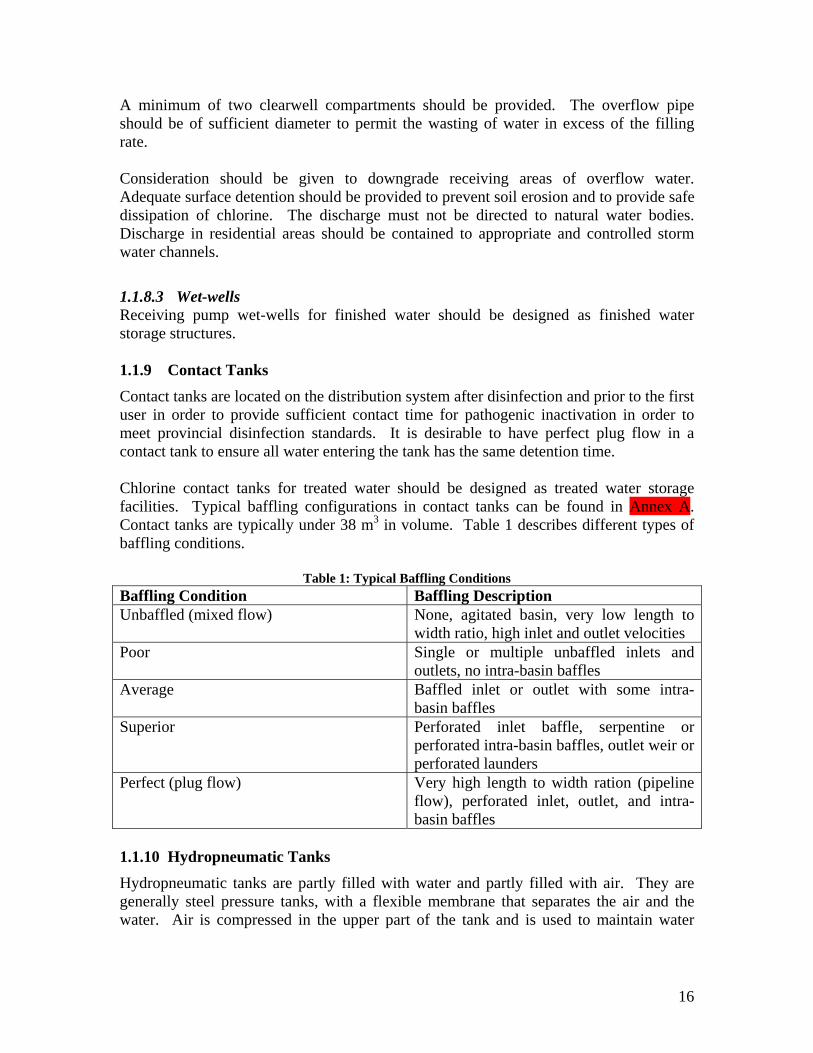
16
A minimum of two clearwell compartments should be provided. The overflow pipe should be of sufficient diameter to permit the wasting of water in excess of the filling rate. Consideration should be given to downgrade receiving areas of overflow water. Adequate surface detention should be provided to prevent soil erosion and to provide safe dissipation of chlorine. The discharge must not be directed to natural water bodies. Discharge in residential areas should be contained to appropriate and controlled storm water channels.
1.1.8.3 Wet-wells Receiving pump wet-wells for finished water should be designed as finished water storage structures. 1.1.9 Contact Tanks
Contact tanks are located on the distribution system after disinfection and prior to the first user in order to provide sufficient contact time for pathogenic inactivation in order to meet provincial disinfection standards. It is desirable to have perfect plug flow in a contact tank to ensure all water entering the tank has the same detention time. Chlorine contact tanks for treated water should be designed as treated water storage facilities. Typical baffling configurations in contact tanks can be found in Annex A. Contact tanks are typically under 38 m3 in volume. Table 1 describes different types of baffling conditions.
Table 1: Typical Baffling Conditions Baffling Condition Baffling Description Unbaffled (mixed flow) None, agitated basin, very low length to
width ratio, high inlet and outlet velocities Poor Single or multiple unbaffled inlets and
outlets, no intra-basin baffles Average Baffled inlet or outlet with some intra-
basin baffles Superior Perforated inlet baffle, serpentine or
perforated intra-basin baffles, outlet weir or perforated launders
Perfect (plug flow) Very high length to width ration (pipeline flow), perforated inlet, outlet, and intra-basin baffles
1.1.10 Hydropneumatic Tanks
Hydropneumatic tanks are partly filled with water and partly filled with air. They are generally steel pressure tanks, with a flexible membrane that separates the air and the water. Air is compressed in the upper part of the tank and is used to maintain water

17
pressure in the distribution system when demand exceeds the pump capacity. It also reduces on-off cycling of pumps. The use of Hydropneumatic (pressure) tanks, as storage facilities is preferred for small water supply systems. When serving more than 150 living units, however, ground or elevated storage is recommended in accordance with sizing requirements as outlined in Section 1.1.4. Pressure tank storage is not to be considered for fire protection purposes. Pressure tanks must meet ASME code requirements or an equivalent requirement of provincial regulations for the construction and installation of unfired pressure vessels. 1.1.10.1 Design of Hydropneumatic Tanks The tank must be located above normal ground surface and be completely housed. The capacity of the wells and pumps in a hydropneumatic system should be at least ten times the average daily consumption rate. The gross volume of the hydropneumatic tank in litres, should be at least ten times the capacity of the largest pump, rated in litres per minute. For example, a 750 L/min pump should have a 7500 L pressure tank. Sizing of hydropneumatic storage tanks should consider the need for chlorine detention time, if applicable. The tank must have bypass piping to permit operation of the system while it is being repaired or painted. Each tank must have a drain, and control equipment consisting of pressure gauge, water sight glass, automatic or manual air blow-off, means for adding air, and pressure operated start-stop controls for the pumps. In large tanks (greater than 7.6 m3), where practical, an access manhole should be 600 mm in diameter.
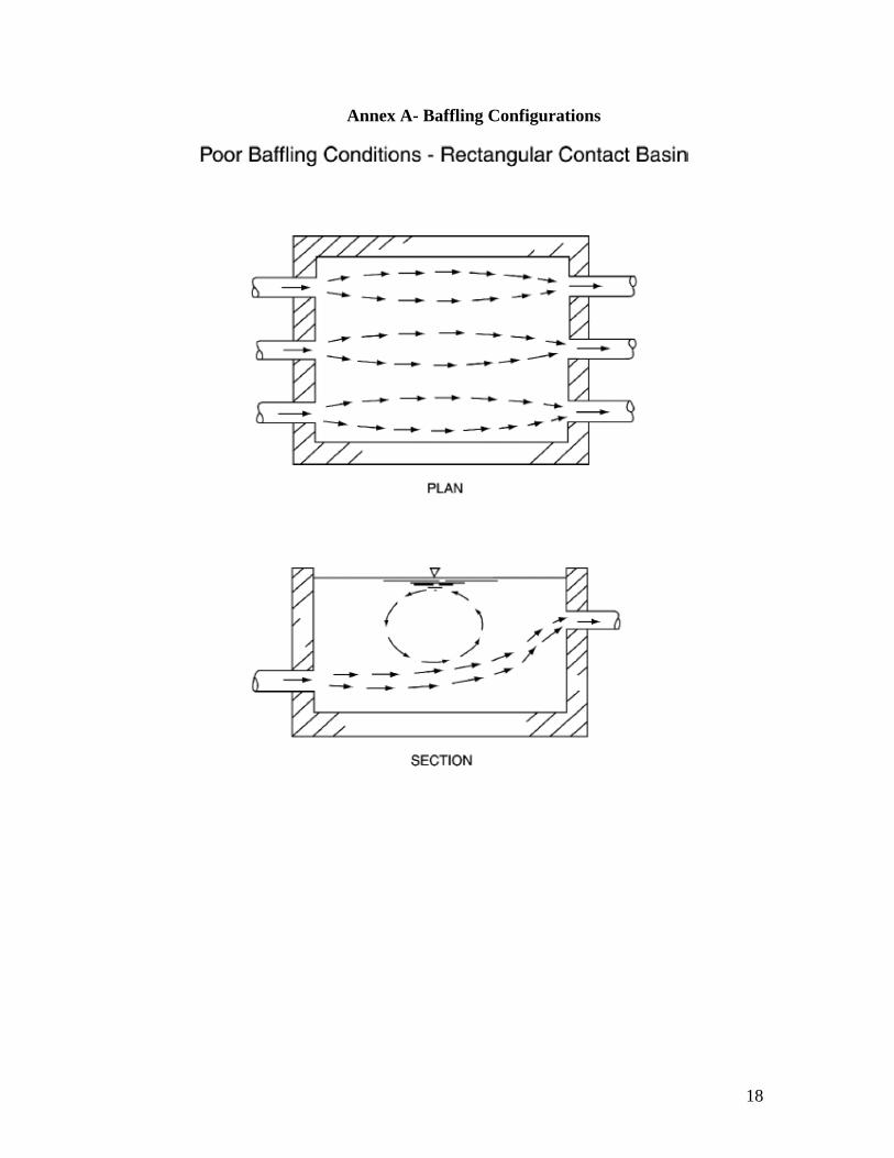
18
Annex A- Baffling Configurations

19

20

21

22

23

APPENDIX D: PERMIT TO CONSTRUCT APPLICATION FORM

Government of Newfoundland and Labrador Environment and Conservation
Instructions: All applicants must complete items 1-9. Complete sections 10, 11, 12, 13, 14, 15 and 16 as applicable. This form along with the attached Fee Schedule and drawings must be sent to the appropriate regional office with an additional copy sent to the headquarters office, Attention Mr. Robert Picco, P. Eng. Note: For submissions to the eastern regional office, a headquarters copy is not required. A. General As required under Sections 36, 37 and/or 48 of the Water Resources Act , SNL 2002, cW-4.01, the undersigned as owner G or agent G do hereby apply for your permission for the construction and installation of:
1. 2. Name & address of proponent (owner) including contact person:
3. Location of project: 4. Project description: 5. Predesign report: Year: Author: 6. Total service population: To date: This project: Future: 7. Status of units for servicing: Type No. to date This project Future
House
School
Medical Institution
Industrial
Other (specify)
Number of units for water service only: Sanitary survey conducted: 8. Permit Fee Submitted: $ Cheque #: 9. Date: Signature:
(If signed by an agent, attach written authorization duly executed by owner)

B. Water System 10. Details of Water Source and Distribution System
Source:
Available yield: (m3/day) Storage: (m3) Present demand: (m3/day)
Type (gravity or pumped):
Bacteriological condition of source: Testing results submitted: Chemical/physical water quality of source: Testing results submitted:
Treatment proposed : (Complete Section 11)
Type of disinfection proposed: Contact time provided: (min.)
Future flows: estimated (m3/day) Present flows: estimated (m3/day) Metered flows: (m3/day) Estimated line pressure: (kPa) Water storage tank proposed (type): Volume: (m3) Location of tank (UTM coordinates and NAD): Tank dimensions (w, l, h/d,h/d): Tank Fill Rate: (L/s) Tank foundation elevation (m): Max tank water level (m): Min tank water level (m):
Expected residence time: Residual chlorination provision:
Fire flows proposed: Hydrants for this project: Noted problems:
11. Water Treatment Plants:
Treatment Objective:
Treatment process proposed (e.g. conventional, membrane, etc.):
Plant capacity: (m3/day) Maximum daily demand: (m3) Design period: (yrs) Storage: (m3)
Pretreatment:
Process description:
Disinfection: Chlorination G UV G Other Corrosion control proposed: Soda ash G Lime G Soda ash/lime combination G Other:
Estimated sludge production: (m3/year) Sludge disposal: Testing facilities at plant: Sanitary facilities:
Backflow prevention device(s) proposed:
Comments/other details:

C. Wastewater System 12. Sanitary Sewers:
Sewage characteristics: Domestic Schools Institutional Industrial Other
% of total
BOD5 (mg/l)
TSS (mg/l) Technical study completed (if yes, study name and date):
Proposed sewer flows: (l/s) Capacity of receiving sewer (l/s) Condition of receiving sewer:
Storm water problems:
Location of outfall (UTM coordinates and NAD)
Length of outfall from last manhole: (m) Depth of water over outfall pipe: (m)
Serviced area: (Ha) Total flow: (m3/day)
Outfall area description: (pond/river/harbour/ocean, dispersion, dilution, tidal action, prevailing winds, etc.)
Existing or potential problems (shoreline impacts, fisheries impacts, damaged outfall, etc.)
13. Sewage Lift Stations Number: Type (wet/dry)
Capacity of each (l/s) Estimated load on each (l/s) Provisions for electrical/mechanical failure

14. Wastewater Treatment Plants:
Treatment process proposed (e.g. activated sludge, fixed film, etc.):
Plant capacity: Hydraulic (m3/day) Organic BOD5 (kg/day) TSS (kg/day)
Plant loading: Hydraulic: Average (m3/day) Peak: (m3/day)
Organic: (kg/day BOD5) Industrial loading: (kg/day BOD5) TSS (kg/day)
Included components (check ):
Pre/Primary: Bar screen G Grit chamber G Comminutor G Microscreening G Primary clarifier G
Secondary: Extended aeration G Contact stabilization G Sequencing batch reactor G Aerated lagoon G
Wetland G Rotating biological contactor G Other
Disinfection: Chlorination/dechlorination G UV G Other Estimated sludge production (m3/year) Sludge digestion: Aerobic G Anaerobic G None G
Sludge disposal
Provision for winter operation (enclosure, etc.) Testing facilities at plant Sanitary facilities
Potable water provided: Yes G No G If yes, backflow prevention device(s) proposed:
Proximity to residential/recreational areas:
Discharge location & area description: (pond/river/harbour/ocean, dispersion, dilution, tidal action, prevailing winds, etc.)
Existing and potential problems (shoreline impacts, fisheries impacts, damaged outfall, etc.)

D. Alterations to a Water Body 15. Pipelines Crossing Streams
Included on drawings (check) General site plan G Cross-sectional plan G Profile G
Location: (UTM coordinates and NAD) Channel slope Depth below stream bed (m)
Physical description of stream bottom:
Material type: Clay G Sand G Gravel G Cobble G Boulder G
Presence of vegetation: None G Sparse G Moderate G Heavy G
Particle size: (mm) Depth to bedrock: (m) Manning=s n:
Hydraulic description:
Minimum flow: (m3/s) Minimum velocity: (m/s)
Maximum flow: (m3/s) Maximum velocity: (m/s)
Construction Details (include method of dewatering, diversion, etc.)
16. Storm Sewer Discharge
Included on drawings (check) Headwall details G Location plan G General site plan G Drainage area G
Setback from river, stream, pond or lake (m)
Hydraulic description:
Maximum flow (m3/s) Maximum velocity (m/s)
Construction Details (include method of dewatering, diversion, etc.)
If additional details are needed on the required information, please contact
Robert Picco, P. Eng. at (709) 729-4290

APPENDIX E: TANK DESIGN EVALUATION TOOL AND CHECKLIST

Design Evaluation Tool for Drinking Water Storage Tanks Community Water & Wastewater SectionWater Resources Management DivisionDepartment of Environment and ConservationDate: March 4, 2011
Tank 1 Tank 2 Tank 3 Grade TypeCharacteristics Town Storage greater or less than 80-120 % required 80-120 % required required = capacity
(required to fill in) Population serviced Residence time greater than 72 hrs 72-24 hrs less than 24 hrs
Tank Type- standpipe, in-ground, elevated, reservoir Fill time less than 80 % of required fill time greater than 80 % of required fill time actual fill time > required fill time
Tank location- beginning, middle, end Volume turnover less than 80 % of required volume turnover greater than 80 % of required volume turnover actual volume turnover > required volume turnover
Tank elevation (m) - at bottom water surface Inlet momentum less than 0.0086 m4/s2 0.0086-0.026 m4/s2 greater than 0.026 m4/s2
Separate inlet/outlet Turbulent inflow* less than 3.58 L/s-m greater than 3.58 L/s-m
Tank level control Inlet configuration flow path along minimum length or obstructed tangential flow path flow path along maximum length
Mixing device * at 5ºC
Design Values Tank shape: C- cylindrical, R- rectangle, S- sphere(required to fill in) Tank dimensions
-rectangular- l (m) -rectangular- w (m) -rectangular- h (m) -cylindrical- d (m) -cylindrical- h (m) -spherical- d (m)Capacity (m3) Hint: Can be the same as calculated
Riser height (m) capacity
Maximum water level (m)Minimum water level (m) Hint: If 0 m, input 0.01 m
Fill time- one cycle (hrs) Enter N/A if value is unknown
Emptying time- one cycle (hrs) Enter N/A if value is unknown Hint: If tank is at beginning of system,
Inlet diameter (mm) use average daily demand, or known
Average fill rate (L/s) Enter N/A if value is unknown pumping rate
Inlet orientation- vertical, horizontal, anglePath of inflow jet- maximum, minimum, tangential, obstructed Hint: 0.25 or consult table
Fraction of maximum daily demand needed for peak balance storage 0.25 0.25 0.25Average daily demand- metered (m3/d) Hint: If metered demand is not
available, use average daily design Fraction of maximum daily demand needed for peak balance storage
Calculated Values Calculated capacity (m3) N/A N/A N/A demand
Water variation (m) 0 0 0Volume min (m3) N/A N/A N/AVolume max (m3) N/A N/A N/AInactive tank volume (%) - potential active volume water never used #VALUE! #VALUE! #VALUE!Dead tank volume (%)- volume air & water not or can't be used N/A N/A N/AActive tank volume (%)- actual turnover volume #VALUE! #VALUE! #VALUE!Average inlet velocity (m/s) #DIV/0! #DIV/0! #DIV/0!Time for tank to fill/draw- one cycle (hrs) 0 0 0Average daily design demand at 340 L/p/d (m3/d) 0 0 0Maximum day demand- metered (m3) 0 0 0
Fire Flow Requirements*
Storage Peak balance storage (m3) 0 0 0 Population Flow (L/s) Duration (h)
Fire storage (m3)* 122 122 122 <1001 17 2
Emergency storage (m3) 31 31 31 1001-3000 64 2
Storage requirement (m3) N/A N/A N/A 3001-5000 110 2
Grade N/A N/A N/A 5001-6000 144 2
6001-10,000 159 3
Residence Time Number of fill/draw cycles per day #DIV/0! #DIV/0! #DIV/0! #DIV/0! 10,001-27,000 189 3
Theoretical average residence time (hrs) #VALUE! #VALUE! #VALUE! #VALUE! 27,001-40,000 318 5
Grade #VALUE! #VALUE! #VALUE! #VALUE! >40,000 378 6
Fill Time Fill time for complete mixing (hrs) #VALUE! #VALUE! #VALUE! #VALUE!#VALUE!
Grade #VALUE! #VALUE! #VALUE! #VALUE!
Volume Turnover Required volume turnover for complete mix (%) #VALUE! #VALUE! #VALUE! #VALUE!#VALUE!
Grade #VALUE! #VALUE! #VALUE! #VALUE!
Inlet Momentum Average inlet momentum (m4/s2) #DIV/0! #DIV/0! #DIV/0! #DIV/0!#DIV/0!
Grade #DIV/0! #DIV/0! #DIV/0! #DIV/0!
Turbulent Inflow Flow/inlet diameter (L/s-m) #DIV/0! #DIV/0! #DIV/0! #DIV/0!#DIV/0!
Grade #DIV/0! #DIV/0! #DIV/0! #DIV/0!
Inlet Configuration #NAME?#NAME?
Grade #NAME? #NAME? #NAME? #NAME?
* From Ontario Design Guidelines for Drinking-Water Systems (actual design should use Fire Underwriters Survey- Water Supply for Public Fire Protection )
Poor Marginal Good

Volume of a sphere: Theoretical average residence time:
Volume of a filling sphere: Number of fill/dreaw cycles per day:
Velocity: Fill time for complete mixing:
MomentumRequired volume turnover for complete mixing:
Maximum day demand:
Momentum:Required storage:
Peak balance storage:
Emergency storage:
3
6dV
32 h
rhV
A
Qv
vQp
PFDemandDailyAverageMDD
MDDPBS 25.0
FSPBSES 25.0
NVV
VHRT
1
minmax
max
cycledrawfillforTimeN
/
24
Q
dVFT 3/2
min3600
9
100%max
V
QFT
StorageEmergencyStorageBalancePeakStorageFireS rateflowvelocityMomentum

Community:
LGP # :
Permit to Construct # :
Potable Water Storage Tanks Satisfactorily Addressed?Yes or N/A No
1 Access road above 100 year flood level (or the highest flood of record)2 Sewers, drains, standing water, etc. at least 15 m from tank3 Service pressure in system is greater than 140 kPa at all times4 Tank capacity = Peak Balance Storage + Fire Storage + Emergency Storage5 Tank design, appurtenances, coatings, cathodic protection, disinfection conform to
latest AWWA and NSF standards6 Water level change in tank less than 9 m7 Retention time in tank less than 72 hrs8 Minimum of 20% turnover of storage volume per fill/draw cycle9 Mixing system
Tank Appurtenances10 Inlet/outlet pipes sized and arranged to promote mixing (diameter, height, orientation)11 Instrumentation to control and monitor water level in tank (water level sensors, altitude
valve)12 Capability to isolate and bypass altitude valve (if present)13 Drain or overflow not connected to municipal sanitary or storm sewer14 Overflow is visible15 Overflow and drain discharge away from tank over splash plate or drainage inlet
structure and not into a natural water body16 Vents and overflow pipes are turned downward17 Vents and overflow pipes are equipped with 24-mesh, non-corrodible screens18 Overflow pipe sized to permit wasting equal to or greater than maximum inflow rate19 Capability to isolate or bypass tank provided20 Drain outlet at least 300 mm above ground surface21 Drain in tank recessed or flush with tank floor22 Tank floor is sloped towards drain23 Roof is watertight and sloped for drainage24 Any additional openings in roof or top of storage tank curbed at least 100 mm and
sleeved with additional shielding25 Antennae and communication equipment properly designed and installed26 More than one vent for large tank (greater than 1900 m3)27 Tank and appurtenances designed to prevent freezing where the lowest one-day mean
temperature is less than -15ºC28 Removable 100 mm high silt stop on outlet pipe29 OHSA requirements met- ladder, fall arrest system, railings, handholds, etc.30 Aviation warning system31 Access hatch is hinged, lockable, at least 600 mm in diameter32 Manhole cover overlaps opening and extends around frame at least 50 mm
In-Ground Tanks33 In-ground tank bottom above groundwater table34 50% of in-ground tank water depth above grade35 In-ground tank has more than one cell36 In-ground tank overflow terminates 600 mm above ground surface37 Vent for in-ground tank- inverted u with opening 600-900 mm above roof or above 100-
year flood level (or the highest flood of record)38 Foundation drain for in-ground tank discharges freely at grade
Community Water and Wastewater SectionWater Resources Management DivisionDepartment of Environment and Conservation

Potable Water Storage Tanks Satisfactorily Addressed?Yes or N/A No
39 Grading around in-ground tank directs water away from tank and prevents standing water within 15 m
40 Access manholes in in-ground tanks- frame 600 mm above the top of covering sod
Above Ground Tanks51 Above ground tank bottom at normal ground surface 52 Above ground tank bottom above 100 year flood level (or the highest flood of record)53 Above ground tank overflow terminates 600 mm above ground surface54 2 opposing manholes are required on welded ground-supported tanks55 Access manholes in above ground tanks- frame 100 mm above surface56 Tank ladder terminates 2.4 m above ground and prevents unauthorized use

APPENDIX F: STANDARD OPERATING PROCEDURES FOR WATER STORAGE
TANKS

Standard Operating Procedures: Drinking Water Systems
Department of Environment and Conservation 1
1 Standard Operating Procedures– Water Storage Tanks
There are a number of useful references that a water system operator can consult for assistance with the operation and maintenance of water storage tanks. The tank manufacturer should provide a standard operation and maintenance manual upon completion of construction. AWWA Manual M42: Steel Water Storage Tanks provides information regarding inspection of existing steel water storage tanks. AWWA Standard G200-04 provides best management practices for system operators including a section on Treated Water Storage Facilities.
1.1 Operator Safety
Access to water storage structures must be restricted to authorized people only. Only trained and experienced workers are allowed to work in or on water storage facilities. The provincial Occupational Health and Safety Act (O.C. 2009-233) and the Occupational Health and Safety Regulations (2009), address work safety issues related to water storage tanks including confined space entry, fall protection, ladders, guardrails, removing lead paint from tanks, repainting, and applying coatings, among others. The latest requirements of the Act, the Regulation and any other relevant occupational health and safety guidelines or best practices must be adhered to when working in and around water storage tanks. Operators climbing or entering tanks should receive training for accessing heights and confined-space entry. When working on or in a water storage tank, the operator must have proper personal safety equipment which may include a safety harness, wire rope grab or other fall arrest/restraint system, friction brakes, carabineers, lanyards, lifelines, anchor points and a hard helmet, among others.
1.2 Water Storage Tank Operation
Water system operators should be aware of and monitor the following operational conditions of their water storage tank:
1. Maximum operational water level 2. Minimum operational water level 3. Time to fill/empty tank 4. Occurrence of overflows 5. Alarms 6. Occurrence of ice formation and ambient air temperature 7. Water temperature throughout tank 8. Chlorine residual levels throughout tank 9. Average daily demand or metered flow on distribution system 10. System pressure at highest and lowest point of use in distribution system

Standard Operating Procedures: Drinking Water Systems
Department of Environment and Conservation 2
Knowledge of the above factors will allow the operator to determine normal operating conditions, and when modifications may be needed to storage tank operation in order to address issues or optimize performance. Issues with water storage tank operation can include:
1. Aging of water 2. Water quality issues (temperature, DBPs, loss of chlorine residual, turbidity) 3. Ice formation 4. Overflows 5. Malfunctioning water level controls 6. Leaks 7. Pump breakdown 8. Possible contamination routes into the tank 9. Different seasonal and weather conditions
Changes in water tank operation by the operator typically involve changing the water storage tank operational range, or maximum and minimum water levels in the tank. Such changes require resetting of the tank level control device. Further changes to tank operation (separation of inlet/outlet, insulating the tank, installing a mixing device, repairing water level controls or pumps, fixing leaks, screen replacements) may require capital infrastructure investment. Records of tank operational conditions should be collected and kept to capture data over time (such as water level and chlorine residuals). To determine if the water storage tank and distribution system can deal with an emergency such as a fire, town and emergency staff should run a practice drill. 1.2.1 Water Level Controls
The controls used to regulate water level in the water storage tank require periodic inspection and maintenance. Maintenance of water level controls should be conducted as per the recommendations of the manufacturer. Altitude valves may require additional maintenance including:
1. The pilot valve should be tested and lubricated. 2. Valves should be exercised. 3. Check for leakage from the altitude valve. 4. If any evidence of wear is found, the altitude valve should be replaced or
repaired.
1.3 Tank Inspections
A comprehensive water storage tank preventative maintenance program can: extend the operational life of the tank; save money on tank rehabilitation; help determine long and short term maintenance planning and budgeting; and achieve compliance with regulatory

Standard Operating Procedures: Drinking Water Systems
Department of Environment and Conservation 3
agency requirements. A tank inspection should consist of careful examination of the tank’s interior, exterior, foundation and accessories. Tank inspections can be used to determine long and short term operation and maintenance requirements of a tank. Potable water storage tanks require routine inspections at the following frequencies:
1. Routine inspections: weekly 2. Periodic inspections: annual 3. Comprehensive inspections including tank cleaning: every 3-5 years
Tank appurtenances, accessories or components can include:
Access hatches Overflows Isolation valves Drains Vents Inlet and outlet riser pipes Pipe connections Freeze prevention devices Tank insulation Silt stops Ladders, railings, catwalks, fall
prevention devices Cathodic protection devices
Security fencing, lighting, alarms and locks
Sampling ports Tank identification plate Level control or monitoring
devices SCADA or telemetry systems Mixing systems Antennas or communication
equipment Sight glass Pressure gauge
Annex A provides a visual glossary of important tank components to assist with tank inspection activities. Tank inspections require condition assessment of:
1. Sanitary conditions– access hatches, low spots on roof plates, vents, overflows, biofilm growth on tank walls, unexplained light penetration, water drips
2. Structural conditions– anchor bolts, foundation, grouting, sealant, wind rods, metal loss or corrosion in steel plates, spider rods, roof trusses, dents, distortions, protrusions, dirt and weeds around the outside base of the tank
3. Safety conditions– ladders, fall prevention, handrails, access, confined space 4. Coatings conditions– percentage and type of failure, thickness, adhesion,
pitting, presence of heavy metals 5. Security conditions– fences, locks, lighting, ladder guards, vents, telemetry
systems (alarms, water quality sensors, water level sensors, control systems) If during a tank inspection a problem is identified, corrective action should be undertaken immediately to assure irreversible damage does not occur.

Standard Operating Procedures: Drinking Water Systems
Department of Environment and Conservation 4
Inspections should take place during dry months when tank surfaces are dry and groundwater is at a minimum. Tools that may be of use in a water storage tank inspection include wide angle binoculars, camera, field chlorine residual test kit, thermometer, pressure gauge, sample containers, level, measuring tape, sampling device, ruler, battery powered flashlight, wet sponge, infrared camera and ultrasonic thickness gauge. Do not use electric powered lights or tools inside the tank. The community should have a written inspection program outlining frequency, procedures and maintenance of records. The inspection program should include such features as routine, periodic and comprehensive inspections. Tank inspection records should be kept on file and used to decide the frequency and scope of future inspections. 1.3.1 Tank Inspection Services
If required periodic or comprehensive inspection activities are beyond the scope and capabilities of the system operator, a qualified inspector should be hired by the community. Only organizations and individuals knowledgeable and equipped to do the work should do inspections. Inspectors must have a thorough knowledge of water storage construction, and be familiar with necessary safety equipment and current safety standards. The firm conducting the inspection should be willing to explain the qualifications of the inspectors. No inspection should be done without a written contract or agreement between the community and inspection firm. The agreement should clearly state the type and scope of the inspection to be provided and any other service or equipment that will or will not be provided. The hired inspection firm should provide an inspection report to the community upon completion of activities. This report should provide pictures of the facility and a description of all inspection findings. The report should provide information on any deficiencies found, recommended corrective measures and their timing. 1.3.2 Routine Tank Inspections
The following inspection list is not inclusive as items requiring inspection depend on each individual storage tank. Routine or weekly inspections and maintenance activities may include the following: confirm gate is locked and fence secure check water quality in tank– chlorine residuals, water temperature check for leakage, rust, penetrations, other obvious tank problems check screens, vents, access hatches all secure

Standard Operating Procedures: Drinking Water Systems
Department of Environment and Conservation 5
check level controls and overflow operational look for indications of spilling from tank overflow look for signs of unauthorized access or vandalism keep record of tank operational monitoring data 1.3.3 Periodic Tank Inspections
The following inspection list is not inclusive as items requiring inspection depend on each individual storage tank. Periodic or annual inspection and maintenance activities may include the following: determine if there is a need for a comprehensive tank inspection or maintenance
activities removal of dirt, weeds and vegetation around the outside base of the tank removal of tree limbs or bushes which may scratch the tank shell check the tank interior for evidence of contamination examine tank shell to foundation connection examine tank for signs of corrosion, leaks, cracks or mineral streaks examine interior and exterior tank coatings for peeling, bubbling, cracking or
corrosion examine concrete tank for signs of concrete deterioration (spalling, cracking, leaking) examine glass coated tanks for cracking, corrosion or other signs of coating
deterioration examine around tank foundation for signs of leakage, abnormal vegetation growth,
ponding, gravel spillage, saturated or eroded soil examine tank foundation for cracks, spalling, exposed reinforcing steel, crumbling,
differential settling examine condition of any grout, fibreboard or sealant located between the tank
foundation and shell for cracks, voids, gaps or deterioration
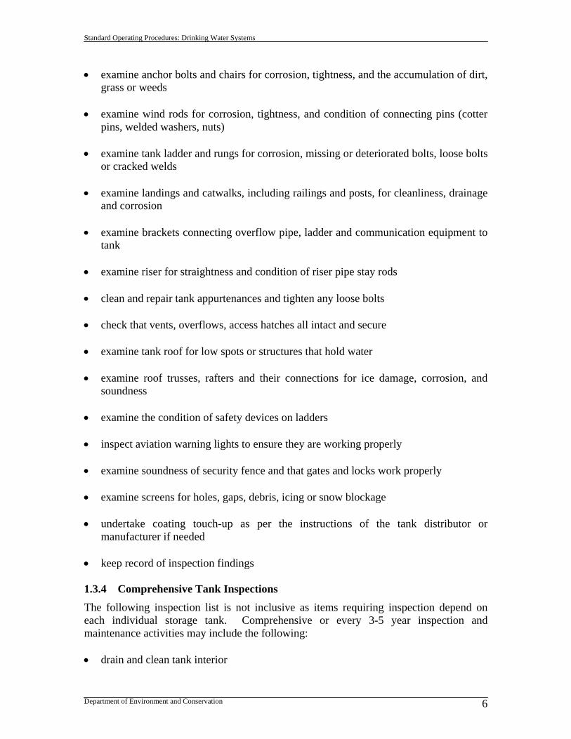
Standard Operating Procedures: Drinking Water Systems
Department of Environment and Conservation 6
examine anchor bolts and chairs for corrosion, tightness, and the accumulation of dirt, grass or weeds
examine wind rods for corrosion, tightness, and condition of connecting pins (cotter
pins, welded washers, nuts) examine tank ladder and rungs for corrosion, missing or deteriorated bolts, loose bolts
or cracked welds examine landings and catwalks, including railings and posts, for cleanliness, drainage
and corrosion examine brackets connecting overflow pipe, ladder and communication equipment to
tank examine riser for straightness and condition of riser pipe stay rods clean and repair tank appurtenances and tighten any loose bolts check that vents, overflows, access hatches all intact and secure examine tank roof for low spots or structures that hold water examine roof trusses, rafters and their connections for ice damage, corrosion, and
soundness examine the condition of safety devices on ladders inspect aviation warning lights to ensure they are working properly examine soundness of security fence and that gates and locks work properly examine screens for holes, gaps, debris, icing or snow blockage undertake coating touch-up as per the instructions of the tank distributor or
manufacturer if needed keep record of inspection findings 1.3.4 Comprehensive Tank Inspections
The following inspection list is not inclusive as items requiring inspection depend on each individual storage tank. Comprehensive or every 3-5 year inspection and maintenance activities may include the following: drain and clean tank interior

Standard Operating Procedures: Drinking Water Systems
Department of Environment and Conservation 7
record depth and rate of sediment accumulation in bottom of tank (cm/yr) examine sediment for signs of internal tank coating flakes determine lead and chromium levels on any paint that appears high in lead or
chromium remove sediment using a soft bristle broom, squeegee or vacuum then rinse with
clean water and flush out tank examine 100% of tank exterior (plates, plate welds, anchor bolts, coating) examine 100% of tank interior (coating, plates) examine 100% of tank wall/legs to foundation connections examine 100% of tank openings (access hatches, vents, overflow, fill/draw pipes,
drain pipe, sensor lines) examine 100% of tank accessories (ladder, railing, water level controls, cathodic
protection) examine 100% of tank roof approximate the percent of rusted area and determine the character of the areas (loose
paint, general corrosion, no paint, etc.) determine the extent, nature and depth of pitting determine total tank film thickness and run adhesion tests take ultrasonic thickness measurements of all metal tank walls and roof spot wet-sponge test interior surface of tank to detect pinholes, cracks or other
compromise in the coating take samples of tank bio-film and bottom sediment clean and repair any wear or damage to tank or appurtenances test tank water level indicators, sensors and gauges for accuracy and calibrate or
replace as necessary
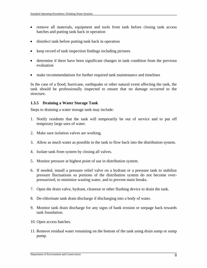
Standard Operating Procedures: Drinking Water Systems
Department of Environment and Conservation 8
remove all materials, equipment and tools from tank before closing tank access hatches and putting tank back in operation
disinfect tank before putting tank back in operation keep record of tank inspection findings including pictures determine if there have been significant changes in tank condition from the previous
evaluation make recommendations for further required tank maintenance and timelines In the case of a flood, hurricane, earthquake or other natural event affecting the tank, the tank should be professionally inspected to ensure that no damage occurred to the structure.
1.3.5 Draining a Water Storage Tank
Steps to draining a water storage tank may include: 1. Notify residents that the tank will temporarily be out of service and to put off
temporary large uses of water. 2. Make sure isolation valves are working. 3. Allow as much water as possible in the tank to flow back into the distribution system. 4. Isolate tank from system by closing all valves. 5. Monitor pressure at highest point of use in distribution system. 6. If needed, install a pressure relief valve on a hydrant or a pressure tank to stabilize
pressure fluctuations so portions of the distribution system do not become over-pressurized, to minimize wasting water, and to prevent main breaks.
7. Open the drain valve, hydrant, cleanout or other flushing device to drain the tank. 8. De-chlorinate tank drain discharge if discharging into a body of water. 9. Monitor tank drain discharge for any signs of bank erosion or seepage back towards
tank foundation. 10. Open access hatches. 11. Remove residual water remaining on the bottom of the tank using drain sump or sump
pump.

Standard Operating Procedures: Drinking Water Systems
Department of Environment and Conservation 9
12. Wash out the tank using low-volume, moderate-pressure pumps, fire-fighting equipment or other means, to remove as much residue as possible from all interior surfaces of the tank.
13. Open all tank isolation valves to allow tank to refill. Ensure no discharge of tank
water to the distribution system until tank has been disinfected. 14. Disinfect tank prior to returning to service as per AWWA Standard C652. Method III
is the preferred method. 15. Take two or more successive sets of microbiological samples taken at 24-hour
intervals. Samples must be microbiologically satisfactory before the tank facility is placed back into operation.
16. Return tank to service.