evaluation of perflouropolyether lubricant lifetime in the ... · evaluation of perflouropolyether...
TRANSCRIPT

Evaluation of Perflouropolyether Lubricant Lifetime in the High Stress and High Stress-Cycle Regime for Mars Applications.
Jason Herman* and Kiel Davis*
Abstract The successful operation of long-life, highly loaded mechanisms used for planetary exploration or autonomous structures assembly will depend upon the ability to effectively lubricate rolling-element bearings. As new tools are developed (i.e. drill, abraders, robotic manipulators, etc.) that interact with their environment in a more direct manner, lubricants will be pushed past the bounds that current scientific literature has published. This paper details results from bearing lubrication lifetime testing performed in support of Honeybee Robotics’ development of the Mars Science Laboratory (MSL) Surface Removal Tool (SRT). This testing was done due to the lack of available data in research literature that is applicable to the lubrication regime the SRT bearings are being designed for. Based on the test results, the chosen bearing arrangement can be used for the SRT Grind Shaft bearings with the use of a Braycote Micronic 601EF grease-plate with a 10 vol% grease slurry fill (50/50 wt% Braycote Micronic 601EF and Brayco 815Z). This arrangement showed no signs of detrimental degradation over the course of the 3x life test. The purely grease-plated bearing ran at a consistently higher torque and showed signs of failure beginning at ~2.2 x 10⁷ revs (~6.3 x 10⁷ stress-cycles) with a torque over-limit failure at ~4.5 x 10⁷ revs (~1.3 x 10⁸ stress-cycles). Barring cold-start torque margin limitations, it is recommended that any long-life bearing application include some vol% grease-pack in addition to a standard grease-plate to reduce parasitic torque and increase bearing life. While these results are specific to a particular environment and loading condition, they demonstrate the extended capabilities of a commonly used flight lubricant outside of the range that is published in current research literature.
Introduction In 2009, the National Aeronautics and Space Administration (NASA) plans to launch the Mars Science Laboratory (MSL) spacecraft that will include a roving vehicle and payload designed for a surface mission of one Martian year (~669 Martian sols or ~687 Earth days) at a yet to be selected landing site. During the nominal surface mission, the vehicle will be expected to traverse multiple kilometers and payload instruments and tools will be required to perform dozens and in some case hundreds of operations. The combination of MSL’s mission life requirement and potentially extreme surface environment at higher latitudes is unprecedented for the Mars Exploration Program. As a quick comparison, NASA’s Viking landers, Pathfinder Sojourner rover, Mars Exploration Rovers (MER) Spirit and Opportunity and the Phoenix Lander (currently en route) were all designed for surface missions of 90 sols or less. Instruments and tools of past missions were designed for dozens of hours of operation as opposed to hundreds of hours as is the case with MSL. While many of the past landed Mars missions have far exceeded their design life, the same (if not more stringent) reliability assurance requirements apply to MSL mechanism designs. At a fundamental component level, MSL’s mechanism design challenges exceed those of past landed Mars missions by nearly an order of magnitude. In other words, what worked for MER will likely not work for MSL. MSL originally planned to carry a Surface Removal Tool (SRT) as part of its payload for brushing and grinding rock surfaces in a manner similar to the MER Rock Abrasion Tool (RAT) [1]. The desired performance improvements over the MER RAT led to an increase in both grinding loads and lifetime requirements (see Table 1). Outside of designing a longer lasting grinding bit, the most significant challenge faced by the design team was to develop a drive train design that would meet the life requirements given all of the constraints. Specifically, the bearings, which supported the grinding bit shaft,
* Honeybee Robotics Spacecraft Mechanisms Corporation, New York, NY
Proceedings of the 39th Aerospace Mechanisms Symposium, NASA Marshall Space Flight Center, May 7-9, 2008
69
https://ntrs.nasa.gov/search.jsp?R=20080023091 2018-07-08T07:23:07+00:00Z

were identified as the highest risk components as they saw the most severe combination of loading conditions and stress cycles. Table 1: MER RAT & MSL SRT Desired Performance MER RAT MSL SRT Minimum Grinding Operations 3 > 80 Grind Area (min. diameter) 45 mm 35 mm Grinding Bit Speed 3000 rpm 750 rpm Grinding Bit Torque 28 mNm 140 mNm Grinding Bit Down Force 20 N 100 N Grinding Operation Duration (max) 3 hr 4 hr Mass 685 grams < 3.5x RAT Volume 1463 cu. cm. < 3.5x RAT PF Min. Operating Temperature -70 C -135C PF Max. Operating Temperature +30 C + 70C This paper describes the MSL SRT grinding bit bearing design and the measures taken to reduce the risk associated with this component. The early part of the SRT design phase was spent developing the grinding bit and in turn deriving requirements for the drive train components including loads, speeds, and maximum allowable size. Once these basic grinding bit bearing requirements stabilized, attention turned to selecting the specific bearing geometry, material and lubricant. After surveying the literature, consulting experts in the field and performing many analysis iterations, a final bearing design was selected. The final design featured New Hampshire Ball Bearing (NHBB) 19-mm angular contact bearings (DB configuration) made from SAE 52100 steel with cotton phenolic retainers. The bearing pair was lubricated with a combination of perflouropolyether (PFPE) based oil and grease (specifically, Castrol Brayco 815Z oil and Braycote micronic 601EF grease) – the recipe is described later in the paper. To verify the design, a test program was conducted which successfully demonstrated a 3x life capability under Mars conditions.
Bearing Design and Lubricant Selection The SRT grinding bit bearing configuration is shown in Figure 1. When grinding, the bearing pair must react cutting forces and loads imparted at the gear mesh. Requirements analysis yielded six distinct SRT operating modes to be considered. These six modes, shown in Table 2, had varying durations, speeds and loads totaling ~20 x 106 bearing revolutions (~60 x 106 stress cycles) at 1x life. The bearing design would need to survive 3x life to pass qualification test requirements.
Grinding Bit
Grinding Bit
Bearing Pair
Drive Gear
Figure 1: Grinding Bit Bearing Configuration
Grinding operations accounted for more than 75% of the bearing revolutions and early analysis using COBRA EHL indicated that mean Hertzian stress levels would approach between 1.38-2.06 GPa (200-300 ksi) during the grinding mode. While this satisfied standards for allowable bearing material contact
70

stress (e.g., AIAA S-114-2005), it posed a concern from a lubricant degradation perspective as the contact stress levels appeared to be beyond the published capability of viable spacecraft lubricant options.
Table 2: SRT Operating Modes
Operating Mode 3x Ops. Required
3x Life (hours)
Bit Load (N, mNm)
Bit Speed (rpm)
3x Bit Bearing Revolutions
Grinding: Difficult Rock 90 360 100, 143 750 16.2 x 10⁶
Grinding: Medium Rock 36 144 50, 76.5 750 6.5 x 10⁶
Grinding: Easy Rock 126 504 25, 43 750 22.8 x 10⁶
Brushing Rock 600 150 10, 10 1500 13.5 x 10⁶
Seek-Scan (locates surface) 852 85 10, 10 60 0.3 x 10⁶
Calibration (homes device) 852 85 0, 0 60 0.3 x 10⁶
The specifications for the selected grinding bit bearing are shown in Table 3. This represented the largest bearing that could be accommodated by the design. A partial ball complement was chosen over a full complement in order to keep parasitic friction as low as possible. Just as important, this bearing was available in quantity from a distributor with a lead time that met the schedule. There was a concern that grinding chatter might damage the bearing if the balls were allowed to become unloaded during the grinding process. Thus, a 124.6 N (28 lbf) preload was selected for the duplexed (back-to-back) pair so that all balls would remain loaded under worst case grinding conditions. With this preload, analysis showed that the maximum mean contact stress in the bearing pair ranged from 1.28 GPa (during Calibration mode) to 1.59 GPa (during Grinding Difficult Rock).
Table 3: SRT Grind Bit Bearing Specifications Specification Value
Manufacturer NHBB Part Number MER-1960SD501 DB Type Angular contact Configuration Inner-race relieved Outer Diameter 19 mm Inner Diameter 6 mm Width 6 mm Ball Diameter 3.572 mm Ball Complement 8 Initial Contact Angle 15 Total Raceway Curvature 0.08 Tolerance Level ABEC 7 Ball & Raceway Material SAE 52100 Steel Cage Type Full-enclosed Cage Material Cotton-phenolic
Allowable Parasitic Torque The total bearing drag at the beginning life was expected to be less than 14 mNm. The SRT grind actuator was sized with enough torque margin to handle parasitic drag up to 28 mNm from the grinding bit bearings during the grinding mode towards the end of life. Lubricant Considerations Figure 2 shows how the SRT grinding bit bearing contact stress and stress cycle requirements stack up relative to several examples of common spacecraft dry and wet lubricant performance. The chart was created using data from [2][7][8][9][10][15]. It is clear that even at 1x life and at the lower end of the contact stress range, the SRT grinding bit bearings are operating in a regime beyond the known capability of these lubricants. One caveat is that this is a two-dimensional chart that does not consider drag torque or speed. Also, in the case of the Brayco 815Z, the chart reflects testing done with 440C or 52100 steel
71

bearings with phenolic cages – thus Brayco 815Z performance with ceramic (S3N4) or ceramic coated (TiC) balls or additives, which is known to be improved, is not shown. Finally, failure criteria vary. Polymerization of the PFPE lubricant does not necessarily constitute a failure for the SRT bearings if there is an adequate reservoir for re-supply of the contact zone with unaltered oil. Likewise, with regard to the MoS2-Ni data, a 40x increase in torque also might not constitute failure for the SRT bearings depending on the running torque at the beginning of life. It does convincingly show however, that both lubricant systems will undergo significant degradation before the SRT achieves 1x life. The preference was to be capable of operating the SRT at -135° C without the use of heaters, although “heat-to-use” was an option. To enable operations at the cold end of the temperature range, dry-film lubricant options were considered. In addition to much lower drag at cold temperatures, other benefits of using a dry-film lubricant include negligible vapor pressure, little surface migration, and valid accelerated-life testing [4]. Specifically, the design team considered coating the balls and races with molybdenum disulfide co-sputtered with nickel (MoS2-Ni) and replacing the phenolic retainer with one made of reinforced, MoS2-containing PTFE (Rulon® AMR). However, MoS2-Ni dry film coatings were ruled out for the following reasons:
• Relevant existing research indicates that SRT bearing contact stresses significantly exceed the known capability of MoS2-Ni coatings. It seemed likely that the initial surface coating on the balls and races would quickly be worn away.
• Unlike a wet lubricant (grease), dry film coatings possess a very limited ability for lubricant replenishment in the contact zone for rolling-element bearings once the initial coating has worn away. Some replenishment may occur as wear particulate from the retainer migrates to the contact zone. By contrast, when mixed to the proper ratio, the grease thickener will not migrate excessively and over the life of the component it will slowly release oil to the contacting metal parts.
0
0.5
1
1.5
2
1.0E+05 1.0E+06 1.0E+07 1.0E+08 1.0E+09 1.0E+10
Life, stress cycles
Mea
n C
onta
ct S
tres
s (G
Pa)
Bray-815Z Bray-815Z Polymerized MoS2 MoS2 40x Torque Increase
1x 3x
SRT
Castrol recommended max. for Bray-815Z
0.15 µm thick
MoS2 wear life Nishimura et al. 1999
1.0 µm thick
Figure 2: SRT Grind Bearing Contact Stress & Stress Cycle Requirement
For these reasons, it was decided to adopt a “heat-to-use” approach and use a wet lubricant (grease). During surface operations, heaters would warm the mechanism to -55° C if necessary before turning on the SRT actuators. However, the protoflight test program would require the mechanism to be demonstrated at -70° C. A PFPE lubricant (Brayco 815Z oil-based grease) was selected over MAC-based
72

or PAO-based based lubricants primarily because it offers the lowest kinematic viscosity at the cold end of the temperature range and has a comparable vapor pressure. The well-documented Achilles’ heel of PFPE lubricants is their tendency to rapidly degrade due to catalytic chemical breakdown of the oil’s polymeric structure when used with common bearing materials (e.g., 440C stainless steel). All polymer molecules are subject to degradation under high mechanical shear and in a lubricant, high shear loads will act to rip apart the molecular chains. PFPE fluids react with bearing surfaces producing “a friction polymer, which, in turn, reacts with existing oxides to produce metallic fluorides [that] are effective, in situ solid lubricants, which reduce friction and prevent catastrophic surface damage” [4]. Unfortunately, these metallic fluorides act as catalysts that speed up the breakdown of PFPE oils – they are Lewis acids (electron acceptors) that catalytically attack and pull the polymer’s molecular structure apart. It is the worst under boundary lubrication conditions where there is a large area of metal-on-metal contact and more of these fluorides are created. PFPE Z-fluids, which perform better at low temperatures, are even more vulnerable to this phenomenon since they possess a more linear structure (straight polymer chains as opposed to branched). To effectively inhibit the degradation of PFPE fluids one must “prevent the catalytic action of strong Lewis acids on the functional surfaces” [3]. There are two ways to reduce the catalytic action. First, one can minimize or avoid operating in a boundary contact regime by a combination of reducing contact stress, increasing operating speeds, keeping temperature down and avoiding lubricant starvation – the goal should be to guarantee the bearing will operate in a elastohydrodynamic (EHD) regime with virtually no metal-on-metal contact. The second option is to use alternative materials (e.g., ceramics, additives) that possess a lower reactivity with the PFPE fluids. However, this was not viable since the schedule could not be met. PFPE Lubrication Evaluation Lubrication modes include EHD, boundary contact, or the mixed regime (see Table 4). For long bearing life, especially for those lubricated with PFPE fluids, it is important that the bearing not be operated in the boundary contact regime for significant amounts of time. The SRT grinding bit bearing lubricant film parameter (Λ) was calculated using both COBRA EHL software and manual calculations to determine the operating lubrication regime [5]. Figure 3 shows the lubricant film parameter for the most severe operating mode (Grinding Difficult Rock).
Table 4: Fluid Lubrication Regimes Lubrication Regime Lubricant Film Parameter (Λ)
Full Separation / EHD Λ > 3.0 Acceptable EHD Λ > 1.5
Mixed 1.0 < Λ < 1.5 Boundary Contact Λ < 1.0
Full ball-raceway separation occurs at Λ > 3.0; however one can assume very little asperity contact, and therefore EHD, for Λ > 1.5 [5]. As shown in Figure 3, the bearings will most likely be operating in a full EHD regime at room temperature (20° C) assuming the bearings are well lubricated. As lubricant is depleted and the contact surfaces become starved, the bearing will begin to operate in a mixed regime and ultimately boundary contact will occur. The analysis showed if the bearing was operating in a starved condition at temperatures exceeding ~20˚ C, there was a high likelihood of boundary contact**.
** One exception was the brushing load case, which is run at 1500 rpm. The analysis showed that the bearing would operate in the EHD regime across the temperature range.
73

0.1
1
10
100
-80 -60 -40 -20 0 20 40 60 80
Temperature (degrees C)
Lubr
ican
t Film
Par
amet
erFull Separation RegimeAcceptable EHD RegimeDifficult Rock - COBRA EHL (750 rpm)Difficult Rock - Hamrock-Dowson (750 rpm)Difficult Rock - Zaretsky Starvation Adjustment (750 rpm)
Test Temperature
1.5
3.0
Figure 3: Lubricant Film Parameter versus Temperature
The remaining question with regard to the bearing and lubrication design was how much lubricant to use. To minimize parasitic torque, especially at temperatures less than -45° C where Brayco 815Z viscosity starts to increase dramatically, grease plating the bearings would be ideal. However, this means the bearings would likely be starved for lubricant and the analysis showed that boundary contact was extremely likely at the higher end of the temperature range. When considering that local self-heating of the bearing would elevate temperatures even more, boundary contact seemed practically guaranteed. It was decided that a verification test must be performed to demonstrate that the bearing design would survive the 3x-life requirement. Room temperature (20° C) was selected as the test temperature for convenience and because it represented a reasonable maximum ambient based on past RAT experience – very rarely was the RAT operated at ambient temperatures above 20° C. Finally, a decision was made to test two bearing sets side by side. One bearing set would be grease plated only, while the other set would be grease plated and filled to 10 vol% with a grease/oil slurry.
Experimental Test Bearings The NHBB bearings (MER-1960SD501 DB) used for the test were procured from a distributor, the Intercontinental Bearing & Supply Company (IBSCO). These bearings had been precision ground for a preload of 27 N (6 lb). The bearings were also lubricated with a MIL-L-6085C synthetic diester oil (Winsorlube L-245X). Several steps were necessary to make the bearings suitable for the SRT bearing life test. First, the Winsorlube oil needed to be replaced with Brayco 815Z. IBSCO handled this process – a process they considered proprietary and certified by NHBB. Because the bearing featured a phenolic retainer, there was significant concern about the re-lubrication process. The concern stems from the fact that porous cotton phenolic retainers, if not sufficiently saturated, can absorb oil from the bearing contact zone [12][13][14]. It is evident from these reports that typical vacuum impregnation processes used in industry cannot fully saturate cotton-phenolic retainers. The retainers continue to absorb oil over the course of years until fully saturated. Furthermore, once fully saturated, there is no significant transfer of oil from the cage to a poorly lubricated raceway or ball. Therefore, it is very important to saturate the retainer with as much oil as possible to minimize the sink effect and prevent a premature starved condition. Members of the design team were permitted to witness the process and bearing mass measurements
74

taken at various points of the process yielded an estimated average of 19.5 mg of Brayco 815Z oil absorbed by each retainer+. This represented a >5 wt% increase to the retainer, which satisfies one spacecraft standard [11], and nearly 85% saturation assuming a 5% porosity. Second, two bearing sets were grease-plated using a 10/90 wt% grease-plate solution of Braycote micronic 601EF and Fluoroclean X100. The bearings were delivered with a thin coating of Brayco 815Z and grease plating with this solution ensured that the 52100 steel components were coated with the grease’s corrosion inhibiting additive (sodium nitrite). Grease plating was accomplished by pouring enough Fluoroclean X100 into a clean glass jar to fully cover a bearing. The Fluoroclean mass was recorded to allow for a calculation of the amount of Braycote Micronic 601EF to add. Once the Braycote micronic 601EF was added and mixed into solution, the grease-plate solution was ready for use. Each bearing was dipped in the solution for 5-10 seconds, placed on a Class 100 clean bench for 10-20 minutes; followed by an oven bake at 66˚C for 60 minutes. Once the bearings were cooled, they were stored until needed. Third, one of the bearing sets was filled an additional 10 vol% with a 50/50 wt% mixture of Braycote micronic 601EF and Brayco 815Z oil. The 50/50 mixture had a lower viscosity than pure grease allowing for cold-temperature operation on Mars. A CAD model was used to estimate the empty space inside the bearing to allow for determination of the correct mass of the 50/50 slurry to add. A total of 170 mg of the slurry was added to bearing pair using a syringe. Finally, in order to achieve the desired preload, a shim was added between the outer races of each bearing pair. To determine the proper shim thickness, measurements were made on the bearings to verify the preload deflection of the bearing pair and correlate COBRA software preload predictions.
Motor
Radial Load Gage
Load Application Housing
Axial Load Gage
Torque Sensor Housing
Figure 4: Bearing Test Stand
+ Subsequent analysis performed by NASA JPL showed that some amount of the Winsorlube remained in the retainer post-processing, however the analysis procedure requires refining to determine the exact amount.
75
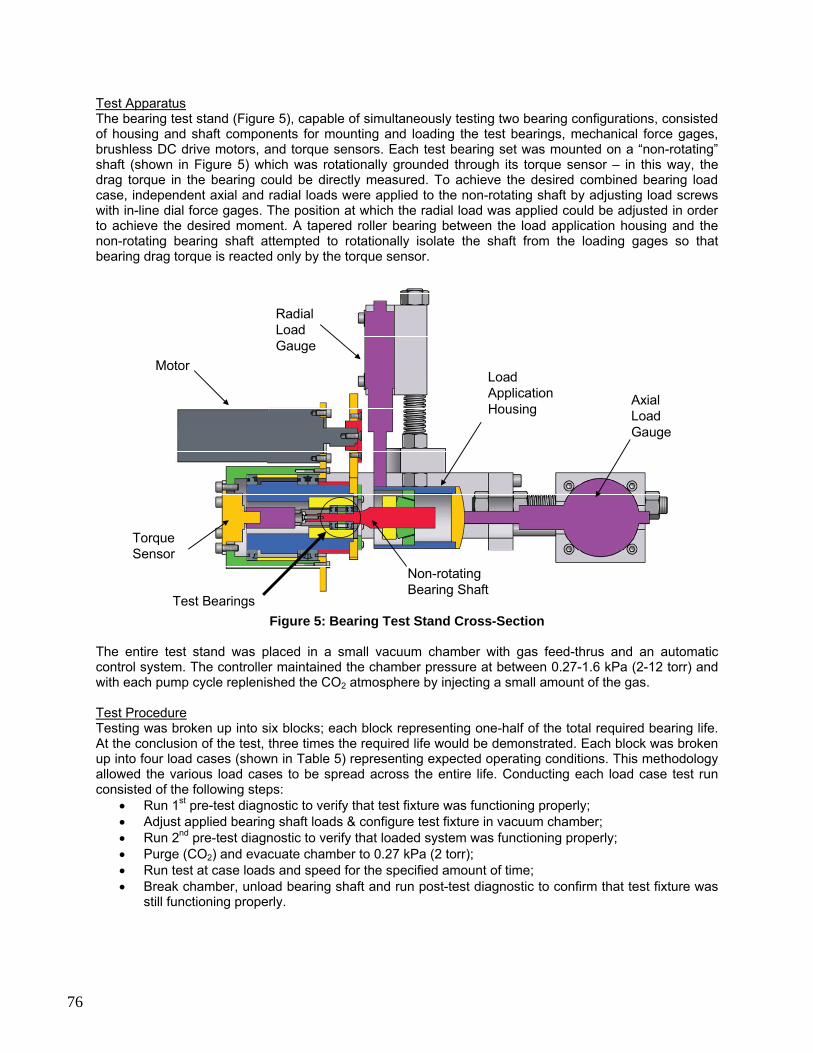
Test Apparatus The bearing test stand (Figure 5), capable of simultaneously testing two bearing configurations, consisted of housing and shaft components for mounting and loading the test bearings, mechanical force gages, brushless DC drive motors, and torque sensors. Each test bearing set was mounted on a “non-rotating” shaft (shown in Figure 5) which was rotationally grounded through its torque sensor – in this way, the drag torque in the bearing could be directly measured. To achieve the desired combined bearing load case, independent axial and radial loads were applied to the non-rotating shaft by adjusting load screws with in-line dial force gages. The position at which the radial load was applied could be adjusted in order to achieve the desired moment. A tapered roller bearing between the load application housing and the non-rotating bearing shaft attempted to rotationally isolate the shaft from the loading gages so that bearing drag torque is reacted only by the torque sensor.
Test Bearings
Torque Sensor
Motor
Radial Load Gauge
Axial Load Gauge
Load Application Housing
Non-rotating Bearing Shaft
Figure 5: Bearing Test Stand Cross-Section
The entire test stand was placed in a small vacuum chamber with gas feed-thrus and an automatic control system. The controller maintained the chamber pressure at between 0.27-1.6 kPa (2-12 torr) and with each pump cycle replenished the CO2 atmosphere by injecting a small amount of the gas. Test Procedure Testing was broken up into six blocks; each block representing one-half of the total required bearing life. At the conclusion of the test, three times the required life would be demonstrated. Each block was broken up into four load cases (shown in Table 5) representing expected operating conditions. This methodology allowed the various load cases to be spread across the entire life. Conducting each load case test run consisted of the following steps:
• Run 1st pre-test diagnostic to verify that test fixture was functioning properly; • Adjust applied bearing shaft loads & configure test fixture in vacuum chamber; • Run 2nd pre-test diagnostic to verify that loaded system was functioning properly; • Purge (CO2) and evacuate chamber to 0.27 kPa (2 torr); • Run test at case loads and speed for the specified amount of time; • Break chamber, unload bearing shaft and run post-test diagnostic to confirm that test fixture was
still functioning properly.
76
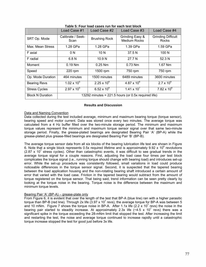
Table 5: Four load cases run for each test block Load Case #1 Load Case #2 Load Case #3 Load Case #4
SRT Op. Mode Calibrate / Seek-Scan Brushing Rock Grinding Easy &
Medium Rocks Grinding Difficult
Rocks
Max. Mean Stress 1.28 GPa 1.28 GPa 1.39 GPa 1.59 GPa
F axial 0 N 10 N 37.5 N 100 N
F radial 6.8 N 10.9 N 27.7 N 52.3 N
Moment 0.19 Nm 0.25 Nm 0.73 Nm 1.67 Nm
Speed 220 rpm 1500 rpm 750 rpm 750 rpm
Op. Mode Duration 464 minutes 1500 minutes 6489 minutes 3600 minutes
Bearing Revs 1.02 x 10⁵ 2.25 x 10⁶ 4.87 x 10⁶ 2.7 x 10⁶
Stress Cycles 2.97 x 10⁵ 6.52 x 10⁶ 1.41 x 10⁷ 7.82 x 10⁶
Block N Duration 13292 minutes = 221.5 hours (or 0.5x required life)
Results and Discussion
Data and Naming Convention Data collected during the test included average, minimum and maximum bearing torque (torque sensor), bearing speed and motor current. Data was stored once every two minutes. The average torque was calculated from a 4 Hz buffer filled over the two-minute storage period. The minimum and maximum torque values represent the minimum and maximum torque sensor signal over that same two-minute storage period. Finally, the grease-plated bearings are designated Bearing Pair ‘A’ (BP-A) while the grease-plated plus grease-filled bearings are designated Bearing Pair ‘B’ (BP-B). The average torque sensor data from all six blocks of the bearing lubrication life test are shown in Figure 6. Note that a single block represents 0.5x required lifetime and is approximately 9.92 x 10⁶ revolutions (2.87 x 10⁷ stress cycles). Other than catastrophic events, it was difficult to see gradual trends in the average torque signal for a couple reasons. First, adjusting the load case four times per test block complicates the torque signal (i.e., running torque should change with bearing load) and introduces set-up error. While the set-up procedure was consistently followed, small variations in load could produce noticeable differences in the torque sensor signal. Second, it is suspected that the tapered bearing between the load application housing and the non-rotating bearing shaft introduced a certain amount of error that varied with the load case. Friction in the tapered bearing would subtract from the amount of torque registered on the torque sensor. That being said, trend information can be seen pretty clearly by looking at the torque noise in the bearing. Torque noise is the difference between the maximum and minimum torque levels. Bearing Pair ‘A’ (BP-A) – grease-plate only From Figure 6, it is evident that over the length of the test that BP-A (blue line) ran with a higher parasitic torque than BP-B (red line). Through 2x life (3.97 x 10⁷ revs), the average torque for BP-A was between 5 and 10 mNm. Figure 7 shows the torque noise in BP-A. After 1.1x life (2.2 x 10⁷ revs) the noise in the bearing pair started to steadily increase. At approximately 2.3x life (~4.5 x 10⁷ revs) there was a significant spike in the torque exceeding the 28-mNm limit that stopped the test. After increasing the limit and restarting the test, the noise and average torque continued to increase rapidly until a catastrophic torque increase stopped the test for good just before 3x life.
77
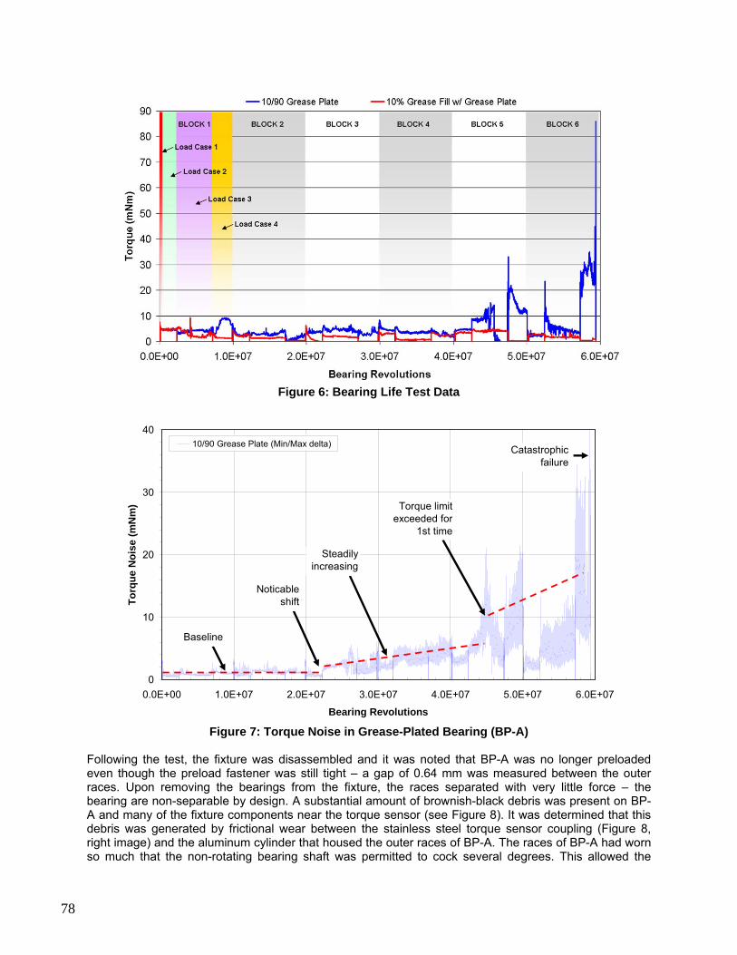
Figure 6: Bearing Life Test Data
0
10
20
30
40
0.0E+00 1.0E+07 2.0E+07 3.0E+07 4.0E+07 5.0E+07 6.0E+07
Bearing Revolutions
Torq
ue N
oise
(mN
m)
10/90 Grease Plate (Min/Max delta)
Noticableshift
Steadily increasing
Baseline
Torque limit exceeded for
1st time
Catastrophic failure
Figure 7: Torque Noise in Grease-Plated Bearing (BP-A)
Following the test, the fixture was disassembled and it was noted that BP-A was no longer preloaded even though the preload fastener was still tight – a gap of 0.64 mm was measured between the outer races. Upon removing the bearings from the fixture, the races separated with very little force – the bearing are non-separable by design. A substantial amount of brownish-black debris was present on BP-A and many of the fixture components near the torque sensor (see Figure 8). It was determined that this debris was generated by frictional wear between the stainless steel torque sensor coupling (Figure 8, right image) and the aluminum cylinder that housed the outer races of BP-A. The races of BP-A had worn so much that the non-rotating bearing shaft was permitted to cock several degrees. This allowed the
78

components to rub together generating debris that contaminated the bearings. Without being able to pinpoint exactly when this began, it’s likely based on the torque signature that the race wear became severe enough to allow rubbing some time during Load Case 2 of Block 5 leading to the first torque over-limit event.
Coupling with debris
BP-A
Non-rotating shaft
Figure 8: Post-Test BP-A (Left – hand separable bearing; Right – shaft with particulate) Further BP-A lubricant observations were not possible due to the excessive contamination by wear particulate shown in Figure8. However, further inspection of the bearing components was conducted using a stereomicroscope. Prior to this inspection, BP-A components were soaked in methylene chloride for 90 minutes. The solution was agitated manually to aid in removing any particulate captured within the bearing cavities. Following the methylene chloride soak, the bearing components were cleaned with isopropyl alcohol and the metallic components were run through a 3-stage ultrasonic cleaning procedure. Microscopic inspection showed that noticeable wear tracks were present on both the inner and outer races (see Figure 9). Very heavy wear existed at two distinct circumferential locations on the inner race while there was more evenly distributed wear on the outer race. This was to be expected since the outer race was rotating and the inner race was stationary with respect to the applied load. With the possible exception of very minor pitting, the balls appeared to be in decent shape. The phenolic retainer also did not exhibit significant wear.
Outer Race Inner Race
Wear Tracks
Figure 9: BP-A Components Post-Test (clean) Bearing Pair ‘B’ (BP-B) – grease-plate plus 10 vol% grease fill Through 3x life (5.96 x 10⁷ revs), the average torque remained at approximately 5 mNm or less – however, it is suspected that the tapered bearing affected the torque sensor signal at the higher load cases (3 and 4). BP-B also ran much quieter than BP-A for the totality of the test with the torque noise averaging between 1-2 mNm. At 2.6x life (5.25 x 10⁷ revs), the first hints of wear started to appear in the torque noise signal with the noise spiking no higher than 4 mNm. During disassembly of the fixture to remove BP-B after the test, no noticeable axial or angular play was found in the test shaft. There was no gap between the outer races of the duplexed pair. When rotated by hand, the bearing pair ran smoothly. A visual inspection confirmed that there was still an oil-grease slurry in the bearing (Figure 10). The bearing pair was weighed before and after the test to determine the amount of lubricant lost. The total mass loss was 56 mg representing 33% of the original 170 mg of slurry
79
added to the bearing before the test. This loss could be due to either the migration of oil from the bearing due to surface wetting or inertial forces or could represent a mass decrease due to the catalytic degradation of the PFPE lubricant. A combination of both loss mechanisms is likely.
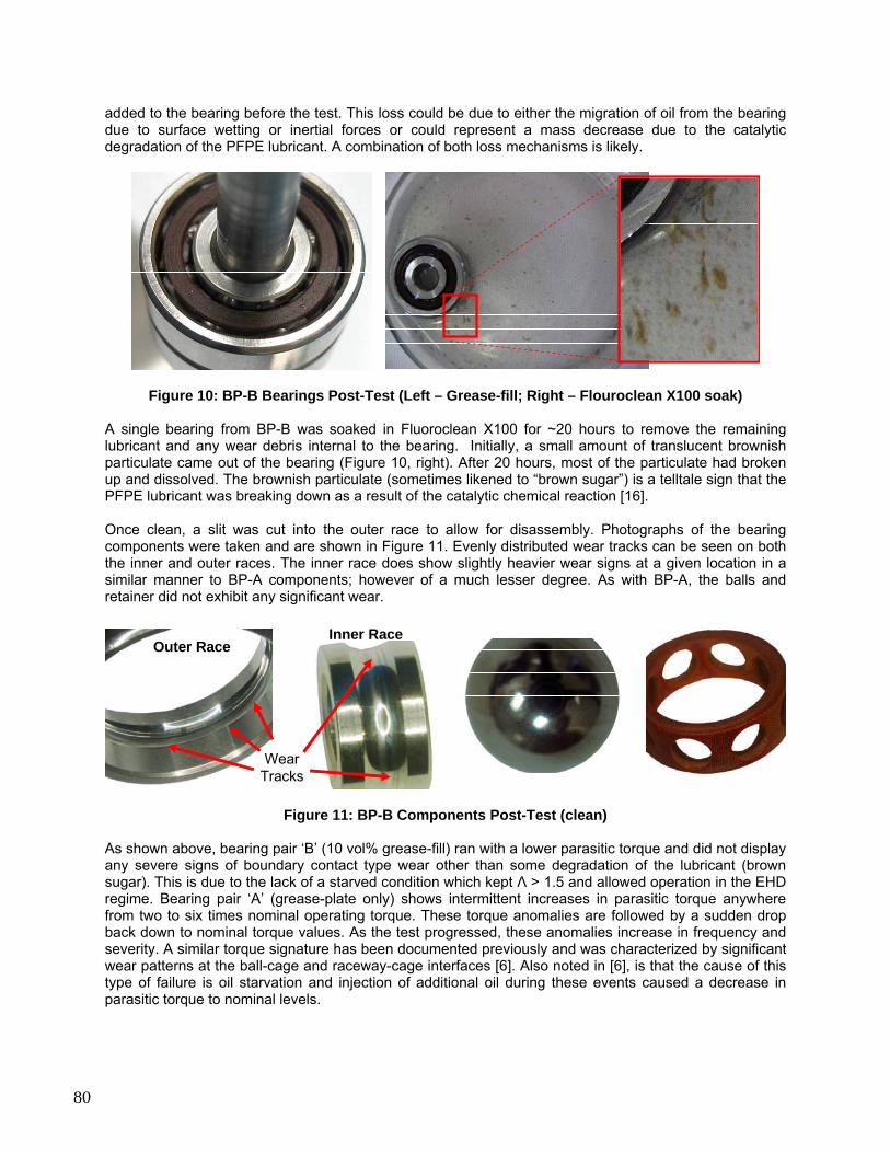
Figure 10: BP-B Bearings Post-Test (Left – Grease-fill; Right – Flouroclean X100 soak) A single bearing from BP-B was soaked in Fluoroclean X100 for ~20 hours to remove the remaining lubricant and any wear debris internal to the bearing. Initially, a small amount of translucent brownish particulate came out of the bearing (Figure 10, right). After 20 hours, most of the particulate had broken up and dissolved. The brownish particulate (sometimes likened to “brown sugar”) is a telltale sign that the PFPE lubricant was breaking down as a result of the catalytic chemical reaction [16]. Once clean, a slit was cut into the outer race to allow for disassembly. Photographs of the bearing components were taken and are shown in Figure 11. Evenly distributed wear tracks can be seen on both the inner and outer races. The inner race does show slightly heavier wear signs at a given location in a similar manner to BP-A components; however of a much lesser degree. As with BP-A, the balls and retainer did not exhibit any significant wear.
Outer RaceInner Race
Wear Tracks
Figure 11: BP-B Components Post-Test (clean)
As shown above, bearing pair ‘B’ (10 vol% grease-fill) ran with a lower parasitic torque and did not display any severe signs of boundary contact type wear other than some degradation of the lubricant (brown sugar). This is due to the lack of a starved condition which kept Λ > 1.5 and allowed operation in the EHD regime. Bearing pair ‘A’ (grease-plate only) shows intermittent increases in parasitic torque anywhere from two to six times nominal operating torque. These torque anomalies are followed by a sudden drop back down to nominal torque values. As the test progressed, these anomalies increase in frequency and severity. A similar torque signature has been documented previously and was characterized by significant wear patterns at the ball-cage and raceway-cage interfaces [6]. Also noted in [6], is that the cause of this type of failure is oil starvation and injection of additional oil during these events caused a decrease in parasitic torque to nominal levels.
80
Conclusions
Based on the test results discussed above, the chosen bearing arrangement with the use of a Braycote micronic 601EF grease-plate with a 10 vol% grease slurry fill (50/50 wt% Braycote micronic 601EF grease and Brayco 815Z oil) meets the SRT grinding bit shaft 3x life requirement (~6 x 10⁷ revs or 1.73 x 10⁸ stress cycles). This arrangement showed minimal signs of degradation over the course of the life test. In contrast, the purely grease-plated bearing does not meet the requirement. The purely grease-plated bearing ran at a consistently higher torque and showed signs of failure beginning at ~2.2 x 10⁷ revs (~6.3 x 10⁷ stress-cycles) with a torque over-limit failure at ~4.5 x 10⁷ revs (~1.3 x 10⁸ stress-cycles). Barring cold-start torque margin limitations, it is recommended that any long-life bearing application include some vol% grease-pack in addition to a standard grease-plate to reduce parasitic torque and increase bearing life. PFPE lubricants, such as Brayco 815Z oil, can be used in the high stress, high stress-cycle regime depending on the application. In the case of mechanisms that have sufficient torque margin, PFPE lubricants can be pushed beyond the currently documented allowable stress conditions. More research is necessary in the field of PFPE lubrication for space and planetary exploration applications where mechanisms tend to be less about precision and more about ruggedness. Data does exist; however test conditions and geometry are not always well documented and many test results are applicable only to Hertzian stress levels below 0.69 GPa. There exist many possibilities to further the abilities of PFPE lubricants and bearing life in general, including the use of hybrid bearings or specialty steels. Carefully documented research will be paramount to future exploration missions that require long life for tools such as abraders, drills and other rugged mechanisms that may operate continuously under high loads.
Acknowledgements
The authors would like to thank all of the SRT program technicians, machinists, designers, engineers and managers at Honeybee Robotics and JPL for their commitment to developing this device. Specifically, the authors would like to thank Mark Balzer of JPL and Jeff Lince of the Aerospace Corporation for their time and technical insights. This work was performed under a contract with Jet Propulsion Laboratory, California Institute of Technology, for the National Aeronautics and Space Administration. References herein to any specific commercial product, process or service by trade name, trademark, manufacturer, or otherwise does not constitute or imply its endorsement by the United States Government or the Jet Propulsion Laboratory.
References
[1] NASA’s Mars Exploration Program. 09 Oct. 2007. NASA. 09 Oct. 2007 <http://mars.jpl.nasa.gov/> [2] Lince, Jeff. Aerospace Corp. Teleconference. March 2007. [3] Conley, P. L. and J. J. Bohner, “Experience With Synthetic Fluorinated Fluid Lubricants”, Proc. 24th
Aerospace Mechanisms Symp., NASA CP-3062, 1990. [4] Jones, W. R., and M. J. Jansen, “Lubrication for Space Applications”, NASA Glenn Research Center,
NASA CR-2005-213424, 2005. [5] Tribology for Aerospace Applications. Ed. E. V. Zaretsky, Illinois: STLE, 1997. [6] Fleischauer, P. D., “Tribology in the Space Environment”, Aerospace Corp., El Segundo, CA, Report
No. TR-97(8570)-2, 1997. [7] Suzuki, M. and M. Nishimura, “Tribological characteristics of ball bearings lubricated with a sputtered
molybdenum disulphide film in a vacuum under a high thrust load”, Proc. 5th European Space
81

Mechanisms and Tribology Symposium, ESTEC, Noordwijk, The Netherlands, 28-30 October 1992 (ESA SP-334, April 1993)
[8] Nishimura, M. and M. Suzuki, “Tribological characteristics of solid-lubricated ball bearings operated
for 10,000 hours in a vacuum”, Japanese Journal of Tribology, 43(3) (1998) 361-374. [9] Loewenthal, S. H., R.G. Chou, G. B. Hopple, and W. L. Winger, “Evaluation of Ion-Sputtered
Molybdenum Disulfide Bearings for Spacecraft Gimbals”, Tribology Trans., 37(3) (1994) 505-515. [10] am_Braycote_601_EF_Mic_USA_English_pds.pdf, <http://www.castrol.com> [11] “The oil impregnation of phenolic resin based materials used in the fabrication of ball-bearing cages”,
ESA PSS-01-712 [12] Bertrand, P. A. “Coray 100 Oil Absorption into Cotton-Phenolic Ball-Bearing Retainers”, Aerospace
Corp., El Segundo, CA, Report No. TOR-0091(9975)-4 [13] Bertrand, P. A. “Oil absorption into cotton-phenolic material”, Materials Research Society Vol. 8 No. 7,
Jul. 1993, Aerospace Corp., El Segundo, CA. [14] Bertrand, Carre and Bauer, Aerospace Corp, TR-94, “Oil Exchange Between Ball Bearings and
Cotton-Phenolic Ball-Bearing Retainers” [15] Nishimura, M. and M. Suzuki, “Solid-lubricated ball bearings for use in a vacuum”, Tribology
International 32 (1999) 637-647. [16] Space Mechanisms Lessons Learned Study. 07 Jan. 2008. NASA. 18 Dec. 2007.
<http://www.lerc.nasa.gov/WWW/spacemech/vol1.html>
82