evaluation of odot’s culvert boring process of odot’s culvert boring process rfp number: 2014-14...
TRANSCRIPT

Evaluation of ODOT’s Culvert Boring Process
RFP Number: 2014-14
Bowling Green State University
Interim-Six-Weeks Report
Principal Investigator: Dr. Alan Atalah
Associate Dean of Graduate Affairs Bowling Green State University
College of Technology, Room 217 Construction Management Bowling Green, Ohio 43403
Phone: 419-372-8354 Email: [email protected]
March, 2014
i
TABLE OF CONTENTS TABLE OF CONTENTS i LIST OF FIGURES iii LIST OF TABLES iv
EXECUTIVE SUMMARY 1
PROBLEM STATEMENT 3
INTRODUCTION TO HORIZONTAL AUGER BORING (HAB) 4
Horizontal Auger Boring 5
History of Auger Boring 5
IN-HOUSE VERSUS CONTRACTING: ADVANTAGES & DISADVANTAGES 7
GOALS AND OBJECTIVES OF THE STUDY 8
WORK PLAN 8
LITERATURE REVIEW ON COST 9
COST BENEFIT ANALYSIS 12
Assumptions 12
Historical ODOT Estimate 13
Horizontal Auger Boring 13
Open-Cut 14
RS Means Estimate 14
Horizontal Auger Boring 14
Open-Cut 16
Ownership and Operation Cost of ABM: ODOT versus Contractor 19
ODOT’s Design, Bidding, and Inspection Cost 20
SPECIFICATIONS FOR THE PROPOSED ABM & QUOTATIONS 21
Specifications for the Proposed Auger Boring System 21
Quotations for the Proposed Auger Boring System 22
ASSISTANCE/CONTRIBUTION FROM ODOT 23
PIPE BURSTING AND RAMMING TESTS 24
INTRODUCTION TO PIPE BURSTING (PB) 24
Pipe Bursting Systems 25
Pneumatic Pipe Bursting 26
Static Pipe Bursting 26
Hydraulic Pipe Bursting 27
Pipe Splitting 28

ii
Pipe Reaming 29
Impactor Process 29
Tenbusch Method 30
When is Pipe Bursting a Preferred Solution? 30
Pipe Bursting Applicability and Limitations 32
INTRODUCTION TO PIPE RAMMING (PR) 35
LITERATURE REVIEW ON COST 36
COST ANALYSIS 36
Assumptions 36
ESTIMATE FOR PIPE BURSTING AND RAMMING TESTS 38
ODOT CONTRIBUTION TO PB AND PR TESTS 38
CONTRIBUTION FROM MANUFACTURERS 39
CONCLUSIONS AND RECOMMENDATIONS 39
Horizontal Auger Boring 39
Pipe Bursting and Pipe Ramming Research Tests 41
REFERENCES 42

iii
LIST OF FIGURES
Figure 1: Diagram showing the pipe jacking operation 4
Figure 2: Layout of an auger boring operation 5
Figure 3: Layout of an auger boring operation 6
Figure 4: Cost/LF to Cross I-75 9
Figure 5: Pipe bursting layout 24
Figure 6: Bursting heads for the different PB systems. 25
Figure 7: Pneumatic pipe bursting 26
Figure 8: Static Pipe Bursting-Sectional Pipe 27
Figure 9: Hydraulic bursting head (Xpandit) in both expanded and contracted positions 28
Figure 10: The static pull bursting head with accessories to cut reinforcing steel in RCP 28
Figure 11: Pipe splitting head (PIM Corporation 2007) 29
Figure 12: Reaming head 29
Figure 13: The Impactor process combines HDD with pipe bursting 30
Figure 14: The Tenbusch method 30
Figure 15: Cost comparison between pipe bursting and open cut replacements 31
Figure 16: The upper and lower limits of historical cost of pipe bursting per linear foot 32
Figure 17: The attenuation lines of the PPS versus distance from the source for different construction pieces of equipment and the attenuations of the 95% PI upper limit lines for the pneumatic bursting in soft soils and hard soils
34
Figure 18: Original culvert consumed by new casing 35
Figure 19: Pipe installation through ramming 35

iv
LIST OF TABLES
Table 1: Pros and Cons of ODOT In-house versus Contracting 7
Table 2: Qualitative costs for open-cut versus trenchless 10
Table 3: Cost factors for pipe Jacking and Microtunneling 11
Table 4: Elements of social costs 12
Table 5: Historical Estimates for Horizontal Auger Boring jobs 14
Table 6: Historical Estimates for Open-Cut Jobs 14
Table 7: RS Means Itemized Estimates for 100 LF of Horizontal Auger Boring Jobs 15
Table 8: RS Means Estimates per LF for Horizontal Auger Boring Jobs 16
Table 9: RS Means Itemized Estimates for Open-Cut Jobs 17
Table 10: RS Means Estimates for Open-Cut Jobs 19
Table 11: RS Means Estimate for Equipment cost to contractor per hour 19
Table 12: Estimate of equipment cost to ODOT per hour 20
Table 13: Summary of Prices for the Auger Boring Machine 22
Table 14: RS Means Itemized Estimates for Pipe Bursting Jobs 37
Table 15: RS Means Estimates per ft. for Pipe Bursting Jobs 37
Table 16: The Original Proposal Cost, Expanded Scope Proposal, and the Difference 41

1
EXECUTIVE SUMMARY According to the report Ohio Research Institute for Transportation and the Environment (ORITE) issued in 2005, ODOT maintains and replaces over 100,000 culverts under Ohio’s priority and general highways. Various construction alternatives can be employed in the installation of new lines, and each method has its strengths and weaknesses relative to the others. However, the selection of the appropriate method will be project based. The overall key questions for this research are:
• When it is recommended to use the open cut and auger boring techniques?
• When do we hire a contractor and when do we use ODOT’s work force?
The key question for this phase of the project was, “is it economically justified for ODOT to purchase a Horizontal Earth Boring Equipment to perform some of the culvert replacements?” To answer these questions, the research team performed the following activities:
• Compared the auger boring and open cut costs per foot from bid prices (contractor’s) of a small number of projects versus the ODOT cost estimates based on the RS Means production rates. This comparison indicated that the contractor’s cost is lower than that of ODOT’s workforce. However, this comparison is unreliable due the small number of bid prices and the insufficient information about the scope of work and the respective prices.
• Compared the auger boring costs per foot using RS Means assuming that the direct cost for the ODOT crews and the contractor’s crews are identical but the overhead and profit expenses are different. This comparison indicated that using ODOT’s workforce and ODOT’s HAB equipment is more economical especially when you consider the additional cost of supervision.
• Compared the estimated cost per hour for HAB equipment based on the cost of ownership, operation, and maintenance ($110/hr.) and the cost estimate using RS Means ($165/hr.). The lower cost of capital for ODOT offers another significant competitive advantage for the ODOT crew. The number of culverts in the State of Ohio indicates that the auger boring crew can be in operation for more days per year than the assumed 75 days/year (20%); the ownership cost can be cut in half if the number of operational days doubles to 150 days/year.
The above cited comparisons indicate that purchasing the HAB equipment is an economical alternative for ODOT. In addition, the training and development of a skillful workforce in this technical area is a significant additional benefit from this purchase. Another critical factor is the ability to handle the unforeseen conditions because the construction crew belongs to ODOT.
Following the directive from ODOT, the research team expanded the scope of this report to include pipe bursting (PB) and pipe ramming (PR) tests. The addition will involve the replacement of four culverts using pipe bursting and pipe ramming. The equipment manufacturers will provide the pipe bursting and ramming systems required for the four culvert replacements and provide one or two technicians to guide the boring and bursting operations. The equipment manufacturers will direct the ODOT personnel on operating the systems.

2
In this report, the research team also included additional information related to pipe bursting and ramming, cost estimates from literature and RS Means, and a cost estimate for the pipe ramming and pipe bursting tests.
The expansion of the project was noted to have the following potential benefits:
• The labor and equipment cost for replacing these additional test culverts will be greatly leveraged because the manufacturers will supply the equipment and the technician to direct ODOT crew.
• The expanded scope will provide the required information to make a decision on whether ODOT would benefit from acquiring a bursting system in the future for its in-house operations.
• The expanded scope will provide ODOT’s construction crew valuable training and development in the advanced technologies of replacing culverts.
• The additional expenses for this expansion are costs that ODOT will still incur when replacing these culverts and the research team anticipates cost savings as a result these tests.
• The expanded scope creates a win-win for ODOT and the manufacturers, and will serve as a contribution to development in the trenchless construction industry where bursting corrugated pipes is a big challenge.
The expanded scope of work will increase the cost to ODOT by $11,274 due to the cost savings of $60,000 for the auger boring equipment. The project duration will increase by four month due to the expansion.

3
PROBLEM STATEMENT
For the purpose of this interim report, culvert is defined as a structure that conveys water or forms a passageway through an embankment and is designed to support a super-imposed earth load or other fill material plus live loads. A culvert will consist of all of the following even though they may support traffic loads directly: (1) any structure with a span, diameter, or multi-cell structure with total span less than 10 feet when measured parallel to the centerline of the roadway and (2) any structure that forms a passageway or conveys water through an embankment not inspected according to the definitions and terms of the Ohio Department of Transportation Bridge Inspection Manual (Ohio Department of Transportation, 2012).
The above-ground infrastructure has been getting more attention and maintenance works than the underground infrastructure because they are “out of sight, out of mind.” Consequently they are failing due to lack of maintenance and proper asset management practices (Salem, et al., 2008). These invisible infrastructures are the foundation of our current civilization and future prosperity, and they deserve to be maintained, repaired, rehabilitated, and replaced in an economical and safe manner that causes the minimum amount of inconvenience to the tax payers. Trenchless technologies offer innovative alternatives to open cut construction that are more economical and convenient when they are employed appropriately (Atalah A. , 2007).
Culverts are critical to drainage and transportation of fluids under highways. Culvert construction in the United States became increasingly necessary with the freeway construction projects initiated under the Eisenhower administration (1953-1961). They serve as conduits for water to drain/pass from one side of the highway to the other. Many of these culverts were designed for a 50-year life cycle, which is now ending (Camp, Boyce, & Tenbusch, 2010). The Ohio Department of Transportation (ODOT) conducts regular inspections and evaluations on its culverts, and based on this condition assessment, makes recommendations. Following the assessment, it is determined whether the culvert(s) requires routine maintenance, rehabilitation, or complete replacement. There are various reasons that may necessitate the replacement of a culvert such as:
• Squatted cross-section of culvert • Sagging of culvert • Collapse of culvert • Need for greater capacity • Increased load due to new construction • Corroded culvert • Eroded backfill • Eroded bedding
If the decision is made to replace the culvert, an appropriate replacement method must be adopted. For the purpose of this interim report, this could be the conventional open-cut construction method or horizontal auger boring (HAB). This replacement of old culverts can be done by ODOT personnel or it can be contracted.
Cost-benefit analysis (CBA), also known as benefit-cost analysis (BCA), is a method that can be used to choose the most feasible choice between or among competing alternatives. The CBA method weighs the total expected costs against the total expected benefits of a given alternative in an effort to determine its feasibility. It will be important to account for the main cost factors

4
including direct costs, indirect costs, and social costs. The social costs would include: road damage, damage to adjacent utilities, damage to adjacent structures, noise and vibration, pollution, vehicular traffic disruption, pedestrian safety, business and trade loss, damage to detour roads, site safety, citizen complaints, and environmental impacts (Gangavarapu, Najafi, & Salem, 2003). Vehicular traffic disruption is perhaps the most critical of these social costs.
This interim report will present a comparison of the cost of replacing culverts using horizontal auger boring (bore and jack) and open-cut construction methods when the construction work is done by ODOT and when it is contracted. This proposal focuses on jack and bore (auger boring) technique.
INTRODUCTION TO HORIZONTAL AUGER BORING (HAB) Pipe Jacking is a process of jacking a pipe with laser guided and manually controlled equipment that requires personnel entry into tunnel boring head for operation as shown in Figure 1. It requires soil with some stand up time, and it cannot handle high water head. The steering is done using steering jacks and an articulated joint in the jacking shield using the guidance of a laser beam positioned to be on the target path of the pipe. It is critical that the rate of excavation and the rate of jacking to be synchronized to ensure stability of the soil, reducing the chance for settlement and heave. The excavated material is transported from the face of excavation to the jacking shaft using electric carts, flight augers, or conveyor belts. The jacking pipe carries axial (horizontal) loads during the construction (jacking) phase from the hydraulic jacks and vertical loads from soil, surcharge, and live loads both during and after jacking (Atalah A. , 1996). Auger boring is a variation of the pipe jacking technique; it follows the same principles, but transports the soils using flight augers inside a jacked casing pipe and using auger boring machine to jack the casing and provide the torque needed to rotate the cutting head (Atalah A. , 1991).
Figure 1. Diagram showing the pipe jacking operation

5
Horizontal Auger Boring Horizontal auger boring (also called the bore and jack method) is a technique for forming a cased horizontal bore hole through the ground, from a drive shaft to a reception shaft, by means of a rotating cutting head. A rotating cutter head at the front of the casing is attached to the leading end of an auger string. Spoil is transported back to the drive shaft by the rotation of helical-wound auger flights within the steel casing pipe. Vertical control, using a water level, is typical (Iseley & Gokhale, 1997). The head is equipped with butterfly wing cutters that excavate the soil in front of the casing with an over cut of half an inch to an inch to reduce the friction between the soil and the casing (Center for Underground Infrastructure Research and Education, 2004). Auger boring is generally used to install steel casing pipe in relatively soft stable ground conditions such as clay, silt or sand with fine material in the soil matrix, above the water table. The auger boring machine advances along a track, which is aligned to drive the casing pipe on the designed installation line as shown in Figures 2 and 3. Once the machine reaches the end of the track arrangement, the auger flight is disconnected from the machine and the machine is retracted to the original starting point on the track allowing a new auger flight to be connected to existing flight and new casing segment to be welded to the existing casing pipe. The excavation and thrust process is repeated until the project is completed (The International Society for Trenchless Technology, 2013). The auger chain is then withdrawn from the casing pipe and the pipe is cleaned of all remaining soil. The carrier pipe can then be installed and the annular space between the two pipes grouted.
Figure 2. Layout of an auger boring operation (The International Society for Trenchless Technology, 2013) and ( Australasian Society for Trenchless Technology, 2010). History of Auger Boring Although this method has evolved over the past 55 years, the major developments have taken place over the past 20 years and have resulted in increased bore lengths and accuracy. As early as 1936, the first boring machines were made from rear ends of old trucks. These machines were first built by CRC machines and are one of the first machines. They were cradle auger boring machines in which the whole system was suspended by pipe laying equipment. The auger boring method was formally developed in the late forties by Vin Carthy, Salem Tool Company and

6
Charlie Kandal. The developments were simultaneous and independent of each other. Machines were originally developed to drill horizontal blast holes into open cast coal mines in Somerset, Pennsylvania where the use of explosives was not effective as the coal became contaminated because of a high degree of disturbance due to the blast. These machines were used for boring from the working face along the bottom of the fireclay stratum, skimming the top of coal (Center for Underground Infrastructure Research and Education, 2004).
Figure 3. Layout of an auger boring operation (Nickol Boring Inc., 2013) and (Purdue University, 2010). In the 1940s, Charlie Kandal founded the Ka-Mo company which manufactured the Ka-Mo auger boring machines which were electrically operated but later ones were gasoline powered. The machine consisted of electric or air motors on a track with a series of holes in the track. By 1951, Ka-Mo claimed the capability to bore 5 inch diameter uncased holes up to 230 LF. In 1961, pipeline welder Al Richmond started manufacturing small Horizontal Earth Boring (HEB) machines which had an engine on top of the gearbox and was driven with a chain. The machine was driven on track with holes in the cross members and T-pins were used to hold it in the ground. He later introduced the 24 inch machine, the “Power Midget.” Richmond also built 30 and 36 inch machines for bigger diameter installations.
In 1970, Leo Barbera built hydrostatic drive machines with a built in slip clutch. If the machine hit a boulder or some other obstruction, it would switch to maximum torque but at the same time block out the thrust. The machine would advance only when the condition was relieved. The other manufacturers of HEB machines include McLaughlin Boring Systems, Horizontal Equipment Manufacturing Inc., Michael Byrnes Manufacturing, Bor-It Manufacturing, Barbco, The Robbins Company, and several other smaller manufacturing firms. There are several contractors who manufacture their own boring equipment (Center for Underground Infrastructure Research and Education, 2004).
Two of the latest developments in the auger boring industry are the pilot tube auger boring which delivers a high level of accuracy on line and grade suitable for gravity applications and the small boring unit which enables boring through soft to medium rock formations and mixed ground conditions.

7
IN-HOUSE VERSUS CONTRACTING: ADVANTAGES & DISADVANTAGES Table 1 shows some of the advantages and disadvantages of both in-house operations and the contracting option. This should form part of the decision making process when choosing between contracting and doing the job in-house.
Table 1: Pros and Cons of ODOT In-house versus Contracting
Pros Cons In-House 1. Flexibility in the work-including
scope and other details of the project
2. Less dispute
3. No need for preparation of bid documents
4. Design and construction can be on going simultaneously.
5. Stability
6. Loyalty-may lead to better work
1. Training required
2. Increased supervision
3. Owner assumes more of risks
4. Inflexible staffing when the contractor can increase and decrease the work pool as the work demands
5. Potential greater liability exposures and increased insurance costs
6. Worker compensation and other employee benefits increases
Contractor 1. High efficiency
2. Specialty works
3. Has the flexibility of using specialized and professional labor on an as-needed basis as opposed to developing in-house capabilities that may not be optimal
4. Avoids the need for overtime expenses for jobs that spill beyond ordinary work hours or into the weekends
5. The contractor bears some of the risk
6. Personnel Issues are avoided: discipline, supervision, benefits
1. Delays due to greater complexity with decision making on issues that need owner approval
2. Delay in communicating upstream and downstream
3. Inconvenience of preparing of bid material and going through the bidding process
4. May not be readily accessible when needed
5. Contract needed and legal costs will be incurred if counsel is hired to draw up contract
There are other factors that ought to be considered and that include: 1. Cost (direct, indirect and social costs)
2. Quality
3. Seasonality of work
4. Contractor availability
5. Agency policies or statutory requirements

8
GOALS AND OBJECTIVES OF THE STUDY The main objective of this study is to compare the cost of replacing culverts using horizontal auger boring (bore and jack) and open-cut construction methods when the construction work is done by ODOT and when it is contracted, and to give recommendations on these construction alternatives that will enhance efficiency. The different methods will be analyzed using the cost-benefit analysis (CBA).
The following goals are set to help meet this objective.
1. Conduct a preliminary CBA based on historical costs of contracted auger boring and open-cut projects, and ODOT open-cut projects.
2. Conduct CBA for ODOT auger boring and open cut projects by employing the use of estimating tools, chiefly the RS Means.
3. Collect auger boring machine (ABM) quotations and give recommendations for the purchase of the ABM.
4. Conduct time studies for the installation of culvert using the auger boring method and ODOT personnel; conduct site tests; collect the relevant data from the project; and conduct comprehensive CBA.
5. Conduct comprehensive CBA based on historical costs and comprehensive industry survey of bidding prices for contractor/consultant auger boring and open-cut projects and ODOT open-cut projects.
6. Conduct a sensitivity analysis on select parameters like depth, soil types, ground water, and culvert diameter, etc.
7. Give recommendations on the different alternatives, and suggest areas for possible improvement on cost and productivity.
8. Provide a decision making matrix to help ODOT select the most suitable technique for the expected site conditions.
The first three goals have been fulfilled as discussed and shown in this report.
WORK PLAN The work plan is broken down into two phases; each has a set of activities that are targeted at meeting the goals and objectives of the project. Here is a summary of the activities of phase 1:
• The research team conducted an extensive literature review related to direct and indirect cost of auger boring and open cut construction alternatives. The literature review afforded a preliminary determination of the most suitable condition for each method of construction along with the cost-benefit analysis for each method.
• The research team solicited and obtained sample historical bid prices of the methodologies under study from ODOT.
• The research team conducted a preliminary cost benefit analysis (CBA) that is based on the literature review, historical data, and RS Means.

9
• The team submitted this interim report eight weeks after commencement of the project that presents the cost analysis of the four methods, a proposed ABM for phase 2 (complete with specifications and costs), and recommendations based on the cost analysis.
LITERATURE REVIEW ON COST A search for previous research on this topic was conducted. A search was run on the TRIS and ITRD, the Web of Science, Google Scholar, Academic Search Complete, and Compendex databases. Each of these databases contains citations to scholarly articles and papers on numerous topics from thousands of international and local journals, technical reports, and conference proceedings and papers.
Goduto and Atalah (2013) compared the design and construction costs of installing a 16” waterline underneath I-75 in Bowling Green, Ohio using four potential alternatives: open-cut with detouring traffic, postponing the installation until resurfacing the interstate to install the line by open-cut, horizontal directional drilling, and auger boring. The study concluded that it could cost $604.50, $134.50, $57.47, and $173.44 per linear foot to install the pipe using Auger Boring, Horizontal Directional Drilling, open-cut with postponing the installation until resurfacing the interstate to install the line, and open-cut with detouring traffic, respectively as shown in Figure 4. It is important to note that the study did not take into consideration social costs which will be a critical factor in the analysis. The study did not involve any sensitivity analysis which is important in giving us a picture of how the methods compare if there is a change in depth, diameter of the pipe, or other critical parameters. This is another important factor in this study.
Figure 4: Cost/LF to Cross I-75 (Goduto & Atalah, 2013).
$0.00$100.00$200.00$300.00$400.00$500.00$600.00$700.00
Auger Boring HorizontalDirectional
Drilling
Postpone theproject
Open Cut

10
Najafi and Kim (2004) conducted a comparison of the life-cycle-cost of open-cut and trenchless pipeline construction. The paper presented an investigation of the cost-effectiveness of constructing underground pipelines with trenchless methods in urban centers relative to the cost of conventional open-cut method. The analysis was qualitative but it paved way for more studies to calculate the “real” life-cycle-cost of construction projects so that design engineers and project owners can compare different alternatives and specify the most cost-effective and environmentally–friendly methods for contractors’ bids. Table 2 presents the results of the LCC comparison.
Table 2: Qualitative costs for open-cut versus trenchless
Cost Factors for Direct Costs Cost Factor Open-Cut Trenchless Mobilization and Demobilization Major Minor Shoring and Sloping Trench Walls Major Minor Dewatering Major Minor Spoil Removal Major Minor Cost of Detour Roads Major Minor Backfill and Compaction Major Minor Reinstatement of Surface Major Minor Construction Equipment Costs Major to Minor Major to Minor Labor Costs Major Minor Material Costs Minor Major
Cost Factors for Indirect Costs Cost Factor Open-Cut Trenchless Head Office Costs Major Minor Field Office Costs Major Minor Field Supervision Costs Major Minor Cost of Temporary Utilities Major Minor
Cost Factors for Social Costs Cost Factor Open-Cut Trenchless Road Damage (Reduction in Life of Pavement, Approximately 40%)
Major Minor
Damage to Adjacent Utilities Major Minor Damage to Adjacent Structures Major Minor Noise and Vibration Major Minor Dust and Air Pollution Major Minor Vehicular Traffic Disruption Major Minor Pedestrian Safety Major Minor Business and Trade Loss Major Minor Damage to Detour Roads Major Minor Site Safety Major Minor Environmental Impact Major Minor Citizen Complaint Major Minor

11
Thomson, Sangster, & Kramer (1998) reviewed economics of three main classes of trenchless technology work: (1) pipe jacking and Microtunneling for sewer installation, (2) horizontal directional drilling or guided drilling for pressure pipelines and cable installations, and (3) sewer pipeline renewal. The major markets of North America and Europe were investigated. The prevailing costs in 1988 were compared with the direct costs of 1998 to establish the trends and costs of the main trenchless technologies. Table 3 shows the cost factors that were considered in the paper in comparing pipe jacking systems (including microtunneling) and open-cut.
Table 3: Cost factors for pipe jacking and microtunneling
Factor Open-Cut Trenchless Depth Major Minor Soil Conditions Major Minor Obstructions Minor Major Water Table Major Minor Shafts Minor Minor Existing Utilities (Paving Included) Major Major Reinstatement Major Minor Traffic Major Minor Piehl (2005) summarizes the trenchless technologies most appropriate for U.S. Department of Agriculture (USDA) Forest Service roadway culvert applications. His emphasis is on techniques for replacing or rehabilitating corrugated metal pipe (CMP) culverts, 18 inches or greater in diameter. The report also gives estimated costs for the trenchless methods and open-cut method. The costs for replacement using pipe bursting were estimated to vary from $100 to $200 per linear foot for 18-inch-diameter pipes and $850 per linear foot for 48-inch-diameter pipes. For auger boring, the costs were estimated to be about $200 per linear foot for a pipe 18 inches in diameter to $1,000 per linear foot for a pipe 60 inches in diameter.
Rehan and Knight (2007) sought to answer the question, “Do trenchless pipeline construction methods reduce greenhouse gas emissions?” This is part of the social cost of the project. Their preliminary analysis found that the use of trenchless construction methods can result in 78 to100 percent lower greenhouse gas emissions than open-cut pipeline installation methods. This is attributed to shorter job duration using less construction equipment and limited or no disruption to traffic flow when using trenchless. Their estimate did not include greenhouse gas emissions resulting from: the production and transportation of additional quantities of asphalt concrete and trench restoration materials; loss of pavement life; and/or pavement maintenance and rehabilitation.
Gangavarapu, Najafi, and Salem (2003) compared the traffic delays and costs involved during utility construction using open-cut and trenchless methods (auger boring). Case studies of two sites involving utility construction were considered in the study. They studied the auger boring technique and evaluated the construction factors that affect project productivity. The research utilized two simulation techniques to simulate the auger boring process and evaluate the productivity of auger boring systems. In the first case study that involved an installation crossing a street, the cost for open-cut was $12,104.70 while that for auger boring was $9,219.50. The project consisted of a 12-inch gravity flow pipe, an 18-inch gravity flow pipe, and an 8-inch

12
plastic cable conduit that were laid across a 30 foot wide road. Cost of auger boring method was estimated at $190.00 per linear foot of pipe to be installed. The second case study involved the installation of a new pipeline parallel to the road. In this case the cost for open-cut was $4,524.00 while that for auger boring was $9,187.00. This second project involved the construction of a 12-inch diameter, 100-foot long storm water pipe at a depth of 5 feet. The cost per foot of pipe was estimated as $90.00 for auger boring and 43.37 for open-cut. It is evident that the cost of traffic disruption contributed significantly to the cost of the project while using open-cut when crossing a pavement/road.
The cost of a culvert replacement project has three components: direct cost, indirect cost, and social cost. The direct cost is the cost of furnishing the labor, material, and equipment needed for the replacement. The indirect cost include the project overhead, mark up, design cost, bidding cost, supervision cost, etc. The above cited direct and indirect cost elements can be tracked and reasonably calculated. The social costs are the costs to the tax payer that are not included in bid price or other contractual documents or tracked by other arrangements such as those shown in Table 4.
Table 4: Elements of social costs
Vehicular traffic disruption (associated delays, vehicle operational cost, and lost production)
Environmental burden and its associated noise, air pollution, visual intrusion, and construction mess
Utilities relocation Damage to the road surface Effect on nearby business and their associated trade losses
Decreased safety for pedestrians and motorists
Damage to detour roads Site safety With over 100,000 culverts under Ohio’s priority and general highways (Ohio Research Institute for Transportation and the Environment (ORITE), 2005) and that ODOT maintains in the state of Ohio, various construction alternatives can be used to install new lines. Each method has its strengths and weaknesses relative to the others and the selection of the appropriate method will be project based. For deep installations of new culverts and where traffic disruption can be costly, HAB could be a suitable alternative. It is important to choose the right method for the right set of circumstances.
COST BENEFIT ANALYSIS This interim report presents a comparison of the cost of replacing culverts using horizontal auger boring (bore and jack) and open-cut construction methods when the construction work is done by ODOT and when it is contracted
Assumptions The following assumptions were made for the purposes of this preliminary CBA:
1. The direct benefits of the projects are the same for horizontal auger boring and open-cut. The assumption is that the finished culvert will perform the same functions irrespective

13
of the construction method used (same size and length, equal design life, and similar capacity and flow rate.)
2. There is no damage to adjacent utilities or structures as a result of the auger boring or open-cut operation.
3. The pavement to be cut (in the open-cut scenario) on the project site is in reasonably good condition and has some anticipated years of life before resurfacing or reconstruction.
4. The work is assumed to be completed on budget and schedule irrespective of the method of construction.
5. For the historical ODOT cost estimates, the effect of inflation on the change in costs is negligible.
Historical ODOT Estimate 30 culvert projects were selected from recent ODOT projects. The selected projects were limited to Type A and Type B conduits. The Ohio Department of Transportation (2014) defines Type A and Type B conduits as:
• Type A conduits are sealed culvert cross drains under pavements, paved shoulders, and embankments. These culvert cross drains are used to convey water from one side of the roadway to the other. These culverts can be either smooth lined or corrugated. Type A conduits are under pavement and open at both ends.
• Type B conduits are storm sewers under pavements, paved shoulders, and commercial or industrial drives. Storm sewers are used to convey water from one manhole or a catch basin to the other. Storm sewers are always smooth lined. Type B conduits have one or both ends closed with a drainage structure.
Horizontal Auger Boring 12 of the selected culvert projects were auger boring projects with culvert diameters ranging from 12” to 48” and installed at depths ranging from 6 feet to 22 feet. A regression analysis was conducted and the regression equation was used to generate the ODOT historical cost estimates in Table 5. From the table we can deduce that the cost does increase with both the increase in depth and increase in diameter of the product. The regression equation used to calculate the cost per foot was:
Cost per ft. = -27.908 + 6.035*Diameter + 15.250*Depth
It is important to note that the small number of projects used in these preliminary study reduce the reliability of this regression equation at this point; further more data from additional projects will fine-tune the regression equation.

14
Table 5: Historical Estimates for Horizontal Auger Boring (Total Cost/ft.)
Depth (ft.) Diameter 6 feet 8 feet 10 feet 24” $208.43 $238.93 $269.43 36” $280.86 $311.36 $341.86 48” $353.28 $383.78 $414.28
Open-Cut 18 of the selected culvert projects were open-cut projects with culvert diameters ranging from 12” to 48” and installed at depths ranging from 3.5 feet to 11 feet. The regression equation was applied to the respective pipe sizes and depths of installation to get the cost estimates per linear foot that are presented in the Table 6. The regression equation for cost per foot follows:
Cost per ft. = -79.234 + 5.244*Diameter + 8.434*Depth
Table 6: Historical Estimates for Open-Cut (Total Cost/ft.)
Depth (ft.) Diameter 6 feet 8 feet 10 feet 24” $97.23 $114.10 $130.97 36” $160.16 $177.03 $193.90 48” $223.10 $239.96 $256.83 Similar to the HAB analysis, the cost per foot increases with the increase in diameter of the product pipe and the increase in depth of installation. These historical costs are estimates at best and may not be a true and accurate representation of the actual cost of installing a culvert using the methodologies under study. We deduce this based on the assumptions made and the data used to generate these costs.
RS Means Estimate
Horizontal Auger Boring For the auger boring option, the construction process was broken down into the following activities: mobilization, preparation of entry and exit pits, equipment setup, delivery and preparation of pipe section, boring operation, restoration and site cleanup, and demobilization
The following assumptions were made in this estimation shown in Table 7:
• 100 ft. long bores
• ODOT estimates are calculated with the following overhead rates: Labor (80%), Material (15%), and Equipment (0%)
• The location cost index of 98% is used to adjust the U.S. National RS Means calculations to reflect local costs. All the direct costs include this 2% reduction

15
Table 7: RS Means Itemized Estimates for 100 LF of Horizontal Auger Boring Jobs
RS Means Section
Description Units Direct costs Total costs
Materials Labor Equip. Direct Contractor ODOT
33 05 23.20
Horizontal boring casing only, 100’ minimum, not including jacking pits or dewatering. Roadwork ½” thick wall, 24” diameter casing
L.F. $129.36 $125.44 $65.66 $320.46 $411.60 $440.22
33 05 23.20
Horizontal boring casing only, 100’ minimum, not including jacking pits or dewatering. Roadwork ½” thick wall, 36"diameter casing
L.F. $237.16 $156.80 $81.83 $475.79 $597.80 $636.80
33 05 23.20
Horizontal boring casing only, 100’ minimum, not including jacking pits or dewatering. Roadwork ½” thick wall, 48” diameter casing
L.F. $333.20 $167.58 $87.22 $588.00 $720.30 $772.04
33 05 23.20 Prepare jacking pits, including mobilization and demobilization for horizontal boring Ea.
$3,087.00 $3,552.50 $3,087.00
33 01 30.74
PVC Pipe Lining, excludes cleaning and video inspection. Pipe relined with one pipe smaller than the original, 24" diameter, original size
L.F. $24.01 $4.24 $2.26 $30.52 $33.87 $37.51
33 01 30.74
PVC Pipe Lining, excludes cleaning and video inspection. Pipe relined with one pipe smaller than the original, 36" diameter, original size
L.F. $79.38 $4.24 $2.26 $85.89 $95.33 $101.19
33 01 30.74
PVC Pipe Lining, excludes cleaning and video inspection. Pipe relined with one pipe smaller than the original, 48" diameter, original size
L.F. $164.64 $4.24 $2.26 $171.15 $189.97 $199.24
Note: Including overhead & profit means the total cost using the overhead and markup of local contractor and the ODOT means the total cost when using the ODOT work force.

16
• A factor of 112% is used to adjust the contractors cost to include the costs to ODOT for contracted jobs. This factor of ODOT’s overhead costs on contracted jobs includes an additional 4% of the bid price for plan preparation and engineering, 6% of the bid price for the inspection, and 2% of the bid price for accounting and administration.
The direct cost and the total cost per foot estimates for auger boring jobs are presented in Table 8. The direct costs represent the costs for materials, equipment, and labor (without the labor burden); which is assumed to be the same regardless of who does the work (ODOT or specialty contractor). The Contractor’s price consists of direct cost, overhead, and profit (O&P). Theoretically, the total cost represents the price that the contractor will charge the customer, but the markup rate can be changed based on supply and demand. RS Means uses an estimated materials overhead of 10%, labor burden of 55%, labor overhead of 10%, and equipment overhead of 10% for estimating the quoted prices from the specialty subcontractor. This contractor price was adjusted by a factor of 112% to reflect the cost to ODOT for the contracted job. For estimating the total cost for ODOT, the assumptions of labor overhead of 80%, material overhead of 15%, and equipment overhead of zero were used.
Table 8: RS Means Estimates per LF for Horizontal Auger Boring Jobs
Estimates Total per ft. Direct Contractor’s Price ODOT’s cost 24" $381.85 $538.72 $508.60 36" $592.55 $816.10 $768.86 48" $790.02 $1,059.29 $1,002.15 The values in the table above show that the cost to ODOT when the job is done in-house is lower than the cost for contracting.
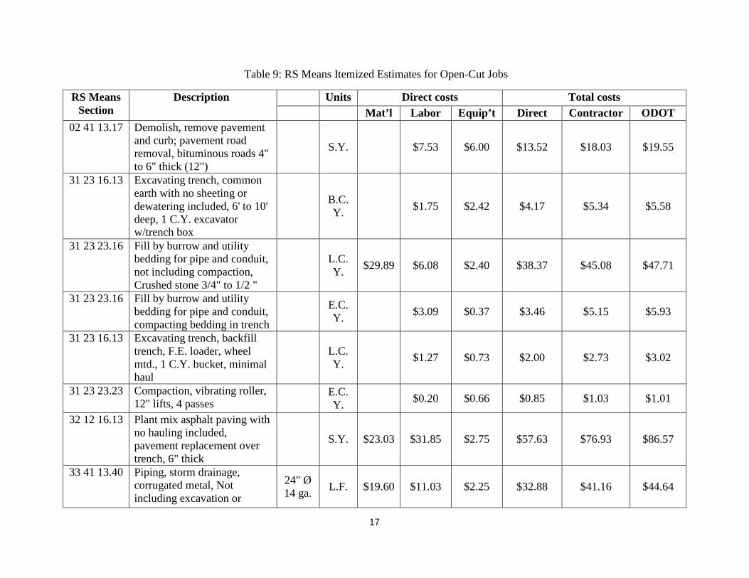
Open-Cut For open-cut, the construction process is broken down into: mobilization, detour & traffic control, asphalt pavement demolition, excavating trench, placing bedding material, laying the pipe, backfilling and compacting, restoration and site cleanup, and demobilization.
The following assumptions were made in the estimation shown in Table 9:
• The trench width was calculated as: Trench Width = 1.25 * outside diameter + 1 foot • Cut pavement width extends 12" on either side of trench • ODOT estimates are calculated with the following overhead rates: Labor (80%), Material
(15%), and Equipment (0%) • Bedding Type 2 with 6" Thickness was used • Native material backfill was used for the trenches • A factor of 112% is used to adjust the contractors cost to include the costs to ODOT for
contracted jobs. This factor of ODOT’s overhead costs on contracted jobs includes an additional 4% of the bid price for plan preparation and engineering, 6% of the bid price for the inspection, and 2% of the bid price for accounting and administration..
17
Table 9: RS Means Itemized Estimates for Open-Cut Jobs
RS Means Section
Description Units Direct costs Total costs Mat’l Labor Equip’t Direct Contractor ODOT
02 41 13.17 Demolish, remove pavement and curb; pavement road removal, bituminous roads 4" to 6" thick (12")
S.Y. $7.53 $6.00 $13.52 $18.03 $19.55
31 23 16.13 Excavating trench, common earth with no sheeting or dewatering included, 6' to 10' deep, 1 C.Y. excavator w/trench box
B.C.Y. $1.75 $2.42 $4.17 $5.34 $5.58
31 23 23.16 Fill by burrow and utility bedding for pipe and conduit, not including compaction, Crushed stone 3/4" to 1/2 "
L.C.Y. $29.89 $6.08 $2.40 $38.37 $45.08 $47.71
31 23 23.16 Fill by burrow and utility bedding for pipe and conduit, compacting bedding in trench
E.C.Y. $3.09 $0.37 $3.46 $5.15 $5.93
31 23 16.13 Excavating trench, backfill trench, F.E. loader, wheel mtd., 1 C.Y. bucket, minimal haul
L.C.Y. $1.27 $0.73 $2.00 $2.73 $3.02
31 23 23.23 Compaction, vibrating roller, 12" lifts, 4 passes
E.C.Y. $0.20 $0.66 $0.85 $1.03 $1.01
32 12 16.13 Plant mix asphalt paving with no hauling included, pavement replacement over trench, 6" thick
S.Y. $23.03 $31.85 $2.75 $57.63 $76.93 $86.57
33 41 13.40 Piping, storm drainage, corrugated metal, Not including excavation or
24" Ø 14 ga. L.F. $19.60 $11.03 $2.25 $32.88 $41.16 $44.64

18
RS Means Section
Description Units Direct costs Total costs Mat’l Labor Equip’t Direct Contractor ODOT
backfill. Corrugated metal pipe, galvanized, bituminous coated with pavedinvert, 20' length
36" Ø 12 ga. L.F. $32.83 $17.64 $5.93 $56.40 $69.09 $75.44
48" Ø 12 ga. L.F. $49.49 $21.07 $7.15 $77.71 $94.57 $101.99
01 54 36.50 Mobilization upto 75 mi. haul dist (150 mi. RT for mob crew) excavator and loader Above 150 H.P.
2 No. Ea $191.10 $627.20 $818.30 $989.80 $971.18
01 54 36.50 Mobilization upto 75 mi. haul dis (150 mi. RT for mob crew) Small equipment, placed in rear of, or towed by pickup truck
2 No. Ea $69.58 $40.18 $109.76 $151.90 $165.42
01 54 36.50 Demobilization upto 75 mi. haul dist (150 mi. RT for demob crew) excavator and loader Above 150 H.P.
2 No. Ea $191.10 $627.20 $818.30 $989.80 $971.18
01 54 36.50 Demobilization upto 75 mi. haul dis (150 mi. RT for demob crew) Small equipment, placed in rear of, or towed by pickup truck
2 No. Ea $69.58 $40.18 $109.76 $151.90 $165.42
Total Mob and Demob $1,856.12 $2,283.40 $2,273.21

19
The total cost per foot estimates for open-cut jobs are presented in Table 10. Similarly, the direct costs represent the costs for materials, equipment, and labor that the person installing pays and do not include markups for profit and labor burden. The contractor cost represents the total cost that the contractor will charge the customer and it includes the cost of materials plus 10% profit, the cost of labor plus labor burden and 10% profit, and the cost of equipment plus 10% profit. It is important to note that the contractor’s profit is directly affected by the forces of demand and supply in the marketplace, and will vary based on the market conditions. This contractor figure also includes a 112% adjustment to reflect the cost to ODOT for the job as described in the assumptions. The ODOT costs are calculated with the following overhead rates: labor (80%), materials (15%), and equipment (0%).
Table 10: RS Means Estimates for Open-Cut Total Cost/ft.
Ø (In)
6 ft. deep 8 ft. deep 10 ft. deep Direct Contractor ODOT Direct Contractor ODOT Direct Contractor ODOT
24" 102.92 147.97 142.91 104.74 150.62 145.40 106.56 153.26 147.89
36" 139.17 198.06 192.26 141.65 201.65 195.64 144.12 205.24 199.02
48" 173.23 245.41 237.37 176.35 249.94 241.64 179.47 254.47 245.91
It is important to note that the social costs which include vehicular traffic disruption, effect on nearby business and their associated commercial losses, damage to detour roads, environmental burden and its associated noise, air pollution, visual intrusion, and construction mess, and decreased safety were not part of the analysis in this first phase. The hypothesis is that the trenchless options will have less social costs as compared to open-cut construction. Both methods will be critical to ODOT and its ability to maintain the integrity of their structures. Knowing when to use what method and whether to do it using the ODOT workforce or to contract it will be the key question in phase 2 of the project.
Ownership and Operation Cost of ABM: ODOT versus Contractor Based on both RS Means and the collected quotations, the research team analyzed the cost per hour for ownership and operation of the ABM. This estimate included the cost of the machine, the annual operating costs, the salvage value, depreciation, equipment overhead rate (EOR) and the interest rate (assumed at 3%). From the RS Means, the 48 inch HAB equipment costs $89/LF and the daily production is 15 LF/day, which means that the daily cost is equal to 89*15=$1335 and the hourly cost, assuming 8 hours/day, is 1335/8 = $166.88 as shown in Table 11.
Table 11: RS Means Estimate for Equipment cost to contractor per hour
Production (ft/day) ft/hr. Cost per ft. Cost per hr. 15 1.875 $89.00 $166.88
The research team used an investment cost (I) of $228,416.63 (average of the collected lowest three quotes), annual operating cost (AOC) of $23,370.55, and a salvage value (SV) of $115,000.00. All the values are present values (costs at year zero). The estimates used were based on the market value (auctioned) of a similar ABM that has been used for eight years, the

20
AOC obtained from various equipment manufacturers, and a first cost from the official quotations that were obtained by Bowling Green State University from the manufacturers and confirmed by prevailing costs of other similar construction equipment.
Based on these values (investment cost, AOC, and SV) and the assumed interest rate, the present value (PV) was calculated to be $277,010.48, $300,381.03, and $323,751.58 for the equipment if it is used for seven, eight, and nine years respectively, then sold. The annual worth (AW) was calculated to be $44,461.94, $42,791.20, and $41,580.66 for equipment if it is used for seven, eight, and nine years respectively, then sold. This formed the basis for the calculations in Table 12 which are estimates of the cost of the equipment to ODOT per hour. The research team assumed a life of seven years (i.e. AW= $44,461.94) and calculated three different estimates: (1) if the equipment is used for 75 days per year; (2) if the equipment is used for 100 days per year; (3) if the equipment is used for 115 days per year. The fuel cost is estimated based on the horse power of the engine (174 HP x 0.04 gal/HP/Hr.) × $4.40 /gal of diesel. The equipment over head rate (EOR) is a combination of interest expense rate, insurance, and storage costs; and it is assumed to be around 10% for ODOT.
Table 12: Estimate of equipment cost to ODOT per hour
Days of work per yr. Cost/hr. Fuel EOR = 10% Total Cost per hr.
75 $74.10 $30.62 $7.41 $112.13 100 $55.58 $30.62 $5.56 $91.76 115 $48.33 $30.62 $4.83 $83.78
Based on these calculations; the contracted HAB equipment cost is around $165 and the owned HAB equipment cost is around $110. We can deduce that it would be more economical for ODOT to do the work in-house than to contract. It is also clear that the more hours per year that the equipment is in operation, the lower the cost per hour to ODOT. If ODOT will have a specialized team that works on the auger boring jobs for a considerable number of days in a year, then it would be reasonable to infer that there will be cost savings for ODOT if they do the work in-house.
ODOT’s Design, Bidding, and Inspection Cost As it is the case for most construction projects, the owner covers many other expenses above the bid prices such as the planning, design, bidding, inspection, and supervision expenses. If ODOT is executing the work using their workforce, the bidding and the supervision expenses will be saved. In this analysis a factor of 112% was used to give a more accurate estimate of the total cost to ODOT for contracted jobs. The supervision expenses is small in magnitude if the work proceeds without problems, but if unforeseen/changed soil conditions are encountered, these expenses can significantly escalate. If ODOT’s workforce is installing the pipe, the planning and design expenses can be significantly lower as ODOT will internally adjust and adapt to the unforeseen conditions with much less overhead expenses associated with the change order. This is a significant part of the risk management plan of the project.

21
SPECIFICATIONS FOR THE PROPOSED ABM & QUOTATIONS Based on the project requirements and the desired auger boring machine, specifications were drafted to acquire the HAB machine for ODOT. The proposed specifications for the HAB machine are shown in the next few paragraphs.
Specifications for the Proposed Auger Boring System BGSU is seeking a quotation for an HAB system that can bore in soft soils and soft rock conditions up to 48” in diameter. A separate quote is needed for the different components and accessories such as water grade indicator, cutting heads, tracks, 100 LF augers of different diameters, etc.
1. Main component and its General description 1.1.The horizontal earth boring machine will primarily consist of :
• Track • Frame assembly • Saddle and saddle attachments • engine • drive train assembly • casing pusher and casing attachment
2. Operational requirements 2.1.Capable of drilling bore sizes 24”, 30”, 36”, and 48”. 2.2.Capable of drilling bores at least 300ft 2.3.Capable of drilling bores in various soil conditions ranging from soft and medium soil
(loose sand/soft clay to dense sand/stiff clay) to soft rock conditions. 3. Accessories and Consumables
3.1.Supply a list of all necessary accessories and their respective prices which include: • Saddle adapters for respective sizes • Casing adapters for respective sizes • Cutting heads for both soil (dirt) and soft rock conditions for sizes 24”, 30”, 36”, and
48”. • Water level/grade indicator • Flight augers (10ft sections) sizes 24”, 30”, 36”, and 48” (10 sections for each size-
100 ft length) 3.2.Supply a list of spare parts are essential for maintenance and repair for the next 12
months and their respective costs 4. Documentation
4.1. The machine operating and service manuals and other necessary manuals (all in English) should be provided
5. Delivery 5.1.Indicate delivery costs including the shipping costs and shipment insurance(if applicable)
to Columbus, Ohio

22
6. Commissioning and Training 6.1.The quotation should include training and providing the relevant literature for the crew
which will include: • The operators • Assisting crew • Maintenance technicians
7. Warranty 7.1.Provide a warranty period beginning from the time of commissioning (minimum 12
months) 8. After sales support
8.1.Estimate of the cost of maintenance, consumables supplies, spare parts, and other operational costs.
8.2.Indicate the location and availability of maintenance and repair facilities and parts (both spare parts and consumables)
Quotations for the Proposed Auger Boring System Official quotations were obtained from six manufacturers. These quotations serve as the best estimates for our investment cost in the auger boring option for ODOT work. Table 13 contains the summary prices for the auger boring machine that were obtained from the manufacturers. The actual quotations are in Appendix 1.
Table 13: Summary of Prices for the Auger Boring Machine
Item Qty Robbins Bor-It Michael Byrne
Barbco American Augers
Mc Laughlin
Machine Price 1 $179,500 $107,380 $154,388 $144,597 $140,340 $106,650 Casing attachment & saddle 3 $12,750 $10,962 $8,475 $9,708 $9,111 $13,760 24" X 10' Auger 10 $26,500 $15,350 $18,840 $15,590 $19,950 $19,080 30" X 10' Auger 10 $31,000 $17,650 $21,920 $17,740 $22,000 $20,800 36" X 10' Auger 10 $34,000 $20,700 $23,890 $20,800 $23,950 $22,920 48" X 10' Auger 10 $39,500 $26,900 $29,440 $27,010 $29,000 $26,320 24" Dirt Cutter head 1 $2,650 $1,885 $1,505 $1,584 $1,694 $948 30" Dirt Cutter head 1 $3,000 $2,149 $1,895 $1,794 $1,733 $1,144 36" Dirt Cutter head 1 $3,250 $2,467 $2,475 $2,378 $1,806 $1,384 48" Dirt Cutter head 1 $3,850 $3,805 $3,020 $3,113 $2,149 $2,836 24" Rock Cutter head 1 $3,950 $1,980 $2,312 $2,575 $2,119 $1,804 30" Rock Cutter head 1 $4,350 $2,267 $2,650 $3,044 $2,457 $2,528 36" Rock Cutter head 1 $4,550 $2,565 $3,830 $3,500 $2,772 $2,888 48" Rock Cutter head 1 $5,000 $4,090 $4,604 $5,254 $3,053 $4,228 Water Level 1 $4,500 $910 $680 $930 $566 $920 Freight
$1,250 - $1,875 $1,250 $1,250 $1,200
Training Wk $5,000 - $6,800 - $1,750 - Total
$364,600 $221,060 $288,599 $260,867 $265,700 $229,410

23
Item Qty Robbins Bor-It Michael Byrne
Barbco American Augers
Mc Laughlin
10% Discount
$26,087 $26,570 Total with Discount
$364,600 $221,060 $288,599 $234,780 $239,130 $229,410
Based upon the above table, the quotes from The Robbins Company and Michael Byrne are not competitive. The quotes from Bor-It, Barbco, American Augers, and Mc Laughlin are competitive. While Bor-It offers the lowest price, the difference is not significant, it is around 1%.
ASSISTANCE/CONTRIBUTION FROM ODOT
• Identify needed 20 culvert crossings replacements to conduct productivity and time study. Ten to be done using ODOT work force, five to be installed using auger boring, and five to be installed using open cut. For the other ten crossings to be executed by contractor: five to be installed using auger boring, and five to be installed using open cut. It is preferred if a few contracted ones are considered before the other crossing to give the ODOT work force the opportunity to practice with the presence of qualified contractor.
• For the ten crossings to be done using ODOT work force, ODOT will provide the information such as the geotechnical conditions, ground water table level, underground utilities, size of culvert, traffic volume of on field test site locations to the research team. It is standard operating procedures that geotechnical investigation will be conducted prior to any boring operation-to the extent possible. The depth of the investigations depends on already available information, magnitude of soil variation, and construction risks at this particular site. The research team and ODOT will identify the level of depth in the geotechnical studies based on the particulars of the jobsite.
• ODOT personnel will conduct the boring operations.
• ODOT will assist the research team in identifying ongoing contracted auger boring and open cut operations under its highways and permit the research team to conduct time and productivity studies.
• ODOT will provide further historical data on culvert replacement projects that were contracted and those that were done by ODOT personnel. ODOT will also provide the research team with bid prices for all work items relevant to the culvert construction projects such as pit construction, mobilization and demobilization, excavation, laying pipes, backfill, etc.
• ODOT will provide estimates, to the extent possible, of all costs relevant to this study.

24
PIPE BURSTING AND RAMMING TESTS Following the introduction to the trenchless technology presentation in the ODOT headquarter on December 10, 201, ODOT instructed BGSU to consider expanding the scope of the project to include pipe bursting (PB) and pipe ramming (PR). While BGSU was collecting quotation for the pipe bursting systems, the difficulty to burst corrugated pipes was raised. The manufacturers indicated that they are willing to test their systems in actual corrugated pipe conditions. This seemed to be win-win for the manufacturer, ODOT, and the trenchless industry.
The research team expanded the scope of this report to include pipe bursting (PB) and pipe ramming (PR) in the next few pages. The additional piece involves replacement of four culverts using the pipe bursting and pipe ramming methods. This part of the report will cover:
• An introduction to pipe bursting.
• An introduction to pipe ramming.
• Applications and limitations of pipe bursting.
• The estimates for pipe ramming and pipe bursting tests.
• Recommendations to ODOT on the way forward.
INTRODUCTION TO PIPE BURSTING (PB) Pipe bursting replacement is a technique for breaking the existing pipe by brittle fracture, using force from within, applied mechanically, and the fragments of the old pipe are forced into the surrounding ground. At the same time a new pipe, of the same or larger diameter, is drawn in behind the bursting tool as shown in Figure 5. The pipe bursting device may be based on a pneumatic tool to exert diverted forward thrust to the radial bursting effect required, or by a hydraulic device inserted into the pipe and expanded to exert direct radial force. Generally a PVC or HDPE pipe is installed in these operations (North American Society for Trenchless Technology, 2013).
Figure 5. Pipe bursting layout (Plastic Pipe Institute, 2008)

25
As the existing pipe is broken, the new pipe is either pulled or jacked into place. The breaking of the old pipe and installation of the new pipe are done concurrently. The new pipe can be of equal or larger diameter than the existing pipe and will follow the same alignment as the existing pipe.
Pipe bursting was developed in the late 1970's in the UK by D.J. Ryan & Sons and British Gas mainly for the replacement of small diameter gas lines. The process involved a pneumatically driven, cone-shaped bursting head operated by a reciprocating impact process. This method was patented in the UK in 1981 and in the United States in 1986; these patents expired in April, 2005 (Plastic Pipe Institute, Chapter 16- Pipe Bursting, 2008). The method was initially used to replace cast iron gas distribution lines but has been continuously developed and is today used to replace water lines, sewer mains and sewer service lines, gas lines, and communication ducts worldwide. Typical replacement pipe sizes range from 50 to 400 mm (2 to 16 in.) in diameter, and lengths between 50 and 100 m (150 and 300 ft) (Ariaratnam & Hahn, 2007). Replacement by pipe bursting is commonly done size-for-size or one upsize above the diameter of the existing pipe. Larger upsizes (up to three pipe sizes) have been successfully done, but the larger the upsizing, the more the energy needed to burst the pipe and the more the ground movement experienced from the displacement (Atalah A. , 2006).
Almost all types of pipes can be burst which include cast iron, cast in place concrete, clay, reinforced concrete, and asbestos cement (AC). Flexible/ductile pipe material such as steel, ductile iron, high density polyethylene (HDPE), and polyvinyl chloride (PVC) require modifications/additions to the bursting head to cut the pipe prior to bursting. Reinforced concrete cylinder pipes (RCCP) cannot be replaced using this method because of the heavy steel reinforcement. Corrugated metal and plastic pipes are generally not good candidates for traditional pipe bursting approaches. Because you can either pull the new pipe or push it in place, almost all types of pipe can be installed using pipe bursting. This would include: high density polyethylene (HDPE), polyvinyl chloride (PVC), clay, steel, fiberglass, polymer, ductile iron, and concrete (Timberlake, 2011) (Plastic Pipe Institute, 2008) (The International Pipe Bursting Association, 2012). Sectional pipes are pushed in place while the continuous pipes that can take tension can be pulled behind the bursting head.
Pipe Bursting Systems Pipe bursting systems are typically classified into three main classes based on the type of bursting head used as shown in Figure 6:
(a) Pneumatic head (b) Hydraulic head (c) Static head
Figure 6. Bursting heads for the different PB systems.
• Pneumatic pipe bursting, which uses pulsating air pressure to drive the head forward and burst the old pipe. A small pulling device guides the head via a constant tension winch and cable.

26
• Hydraulic expansion, where the hydraulic head expands and closes sequentially as it is pulled through the pipe, bursting the pipe on its way.
• Static pull, where a static head with no moving internal parts is used. The head is simply pulled through the pipe by a heavy-duty pulling device via a segmented drill rod assembly or heavy anchor chain (Atalah, Sterling, Hadala, & Akl, 1998)
Pneumatic Pipe Bursting
In the pneumatic system, the bursting tool is a soil displacement hammer driven by compressed air and operated at a rate of 180 to 580 blows per minute. The percussive action of the hammering cone-shaped head is similar to hammering a nail into the wall; each hammer pushes the nail a short distance as shown in Figure 7. With each stroke, the bursting tool cracks and breaks the old pipe, the expander combined with the percussive action of the bursting tool, push the fragments and the surrounding soil providing space to pull in the new pipe. The expander can be front-end (attached to the front end of the hammer) for pipes smaller than 12” or back-end (attached to the backend of the hammer) for pipes larger than 12”. The frontend expander allows withdrawing the hammer through the new pipe after removing the expander at the exit pit (Plastic Pipe Institute, 2008).
Figure 7. Pneumatic pipe bursting (Najafi M. , Trenchless Technology: Planning, Equipment, and Methods, 2013)
Static Pipe Bursting In the static pull system, a larger tensile force is applied to the cone-shaped expansion head through a pulling rod assembly or cable inserted through the existing pipe. As seen in Figure 8,

27
the cone transfers the horizontal pulling force into a radial force, breaking the old pipe and expanding the cavity providing space for the new pipe (Plastic Pipe Institute, 2008). Sectional pipes are pushed into place by hydraulic jacks while the continuous pipes are pulled behind the cone.
(a) Sectional Pipe (b) Continuous Pipe
Figure 8. Static Pipe Bursting-Sectional Pipe
Hydraulic Pipe Bursting In the hydraulic expansion system, the bursting process advances from the insertion pit to the reception (pulling) pit in sequences, which are repeated until the full length of the existing pipe is replaced. In each sequence, one segment of the pipe (which matches the length of the bursting head) is burst in two steps: (1). the bursting head is pulled into the old pipe for the length of the segment, and (2). the head is expanded laterally to break the pipe as shown in Figure 9 (Atalah, Sterling, Hadala, & Akl, 1998).
There are other additions/modification to the above mentioned pipe bursting systems that are designed to replace flexible pipes, advance segmental pipes, or assist in the bursting. These systems include:
1. Pipe Splitting
2. Pipe Reaming (Inneream)
3. Impactor (Earthtool) Process, and
4. Tenbusch Method

28
Figure 9. Hydraulic bursting head (Xpandit) in both expanded and contracted positions (Atalah, Sterling, Hadala, & Akl, 1998).
Pipe Splitting The North American Society for Trenchless Technology (NASTT) defines pipe splitting as a replacement method for breaking an existing pipe by longitudinal slitting or cutting with simultaneous insertion of a new pipe of the same or larger diameter behind the splitting tool (NASTT 2005). Pipe splitting replaces ductile material pipes, which does not fracture using pneumatic and static bursting techniques. This system has splitting wheels or cutting knives that slit the pipe longitudinally. Figures 10 and 11 show examples of the pipe splitting heads.
Figure 10. The static pull bursting head with accessories to cut reinforcing steel in RCP (TT Technologies, 2004).

29
Figure 11. Pipe splitting head (PIM Corporation 2007)
Pipe Reaming Pipe reaming is a patented pipe replacement technique that uses a conventional horizontal directional drilling (HDD) machine with minor modification. The drill rods are pushed through the old pipeline and connected to a special reamer (see Figure 12). The new pipe string is attached to the reamer via a swivel and towing head. As the drill rig rotates and simultaneously pulls back the drill pipe, the old pipe is grinded and replaced by the new HDPE pipe. Removal of the old pipe is accomplished by mixing the grinded material with the drilling fluid and transferring the mix to an entry or exit point for removal via a vacuum truck. Directional drilling contractors can inexpensively use modified reamers of various types depending on the pipe materials and ground conditions. Pipe reaming is limited to non-metallic pipeline replacement. According to Nowak Pipe Reaming, Inc., the patent holder for the InneReam System, the surrounding environmental conditions (groundwater, sand, rock, concrete encasement, etc.) that prohibit other procedures are not obstacles to successful installations (Hayward 2002).
Impactor Process The patented Impactor process is another system that combines the HDD with pipe bursting as shown in Figure 13. The bursting head (Impactor) receives air through the HDD stems. The HDD is connected to the air supply and is positioned to drill out to a manhole. Then the HDD stem is pushed through old pipe to the next manhole and drilled back to the entry manhole. The Impactor device, after it is attached to the drill stem and to the replacement pipe, is pulled into the old pipe. While pulling back, the Impactor system activates and bursts the old pipe. The combined actions -of pulling using the HDD rig and of hammering of the Impactor device- breaks up the old pipe and replaces it with the new pipe. The Impactor system can overcome blocked old pipes.
Figure 12. Reaming head (Plastic Pipe Institute, 2008).

30
Figure 13. The Impactor process combines HDD with pipe bursting (Plastic Pipe Institute, 2008).
Tenbusch Method The Tenbusch method allows the installation of segmental pipes such as VCT, RCP, fiberglass, ductile iron, etc. This method relies on hydraulic jacks that push the pipe similar to those used in pipe jacking as shown in Figure 14. The major advantage of this method is that it annihilates the need for a lot of space to connect and string the pipe.
Figure 14. The Tenbusch method When is Pipe Bursting a Preferred Solution? When faced with pipeline and culvert problems, installing a new line parallel to the old one, then grouting the old one is an alternative that can be used. In that case, the new culvert could be

31
installed using open cut or other trenchless techniques for new installations such as auger boring. Alternatively, the pipeline can be rehabilitated by inserting a new lining or replaced by pipe bursting. There are several pipe lining technologies available such as cured in place pipe, deform and reform, and slip-lining. The main advantage of the lining methods over pipe bursting is the need for small or no access excavation to the pipeline. However, pipe bursting has the advantage of increasing the pipe capacity by more than 100%. The unique advantage of pipe bursting over pipe lining techniques is the ability to upsize the service lines. For pressure applications, a 41% increase in the inside pipe diameter doubles the cross sectional area of the pipe and consequently doubles the flow capacity of the line. For gravity applications, a 15% and 32% increase in the inside diameter of the pipe combined with the smoother surface of the new pipe can produce an increase in the flow capacity of 100% and 200% respectively. Pipe bursting is most cost advantageous compared to the lining techniques when (1) there are few lateral connections to be reconnected within a replacement section, (2) the old pipe is structurally deteriorated, and (3) additional capacity is needed.
Pipe bursting has substantial advantages over open cut replacements; it is much faster, more efficient, and often less expensive than open cut especially in deep installations. The increased depth requires extra excavation, shoring, and dewatering which substantially increases the cost of open cut replacement. The increased depth has a minimal effect on the cost per foot for pipe bursting as shown in Figure 15 (Poole et al 1985).
Figure 15. Cost comparison between pipe bursting and open cut replacements (Poole et al 1985)
Pipe Bursting Open cut favorable conditions Open cut unfavorable conditions
Depth (LF)
Cos
t of I
nsta
llatio
n

32
Figure 16 provides the upper and lower limits of historical cost of pipe bursting per linear foot according to (Simicevic & Sterling., 2001). For 24 inch pipe replacement, the lower limit is $95 and the upper limit is $255. Cost saving from pipe bursting could be much more if the soil is hard rock because deep rock excavation is extremely expensive in open cut. Additionally, open cut can cause significant damage to nearby pavements, buildings, structures, and green areas (Atalah 2004).
Figure 16. The upper and lower limits of historical cost of pipe bursting per linear foot according to (Simicevic & Sterling., 2001). Specific studies carried out in the US have shown that pipe bursting cost savings are as high as 44% with an average savings of 25% compared to open cut (Fraser et al 1992). In addition to the direct cost advantage of pipe bursting over open cut, as a trenchless technique, it has several indirect cost savings. Less traffic disturbance, reduced road or lane closure, less time for replacement, lower business interruption, minimal interference with other utilities, superior safety (for both operators and the public) due to reduced open excavation, and minimal environmental intrusion are some examples of these indirect cost savings.
Pipe Bursting Applicability and Limitations Pipe bursting is used to replace water lines, sewer mains, and gas lines; as well as sewer lateral connections. Typical length of replacement run is between 300 feet and 500 feet; however, longer drives have been completed successfully in favorable conditions. The size of pipes being burst typically range from 2” to 30”, although pipes of larger sizes can be burst. Pipe bursting is
$-
$100
$200
$300
$400
$500
$600
6 8 10 12 14 16 18 20 22 24 26 28 30 32 34 36 38 40 42 44 46 48
Size to Size - Lowerlimit
Cost
/LF
Diameter (inch)

33
commonly performed size-for-size and one-size upsize above the diameter of the existing pipe. Larger upsize (up to three pipe sizes) have been successful, but the larger the pipe upsizing, the more energy needed and the more ground movement will be experienced. It is important to pay close attention to the project surroundings, depth of installation, and soil conditions when replacing an existing pipe especially in unfavorable conditions such as expansive soils, repairs made with ductile material, collapsed pipe, concrete encasement, sleeves, and adjacent utility lines (Atalah, Sterling, Hadala, & Akl, 1998). For culverts with shallow cover, bursting may cause surface heave which may damage the road. The impact area must be determined before the operation to minimize the damage to the road. In addition such shallow pipes are more economical to replace using open cut. There are culverts with shallow cover (less than 36”) that could pose a special challenge when considering pipe bursting as a replacement method.
In large diameter pipe bursting operations, particularly during upsizing, there is legitimate concern about potential damage of nearby facilities and structures. Based on analysis of ground movement and vibrations associated with large-diameter pipe bursting when the pipe trench is in a rock formation, Atalah (2006) stated with 95% confidence that: sound residential structures would be safe at a distance of 3.3m or more from the bursting head, commercial structures would be safe at a distance of 2.6m or more from the bursting head, and buried structures would be safe at a distance of 2.3m or more from the bursting head. See Figure 17.
Pipe bursting also has the following limitations: (1) excavation for the lateral connections is needed, (2) expansive soils could cause difficulties for bursting, (3) a collapsed pipe at a certain point along the old pipe may require excavation at that point to allow the insertion of pulling cable or rod and to fix the pipe sag, (4) point repairs with ductile material can also interfere with the replacement process, (5) if the old sewer line is significantly out of line and grade, the new line will also tend to be out of line and grade although some corrections of localized sags are possible, and (6) insertion and pulling shafts are needed specially for larger bursts (Atalah, Sterling, Hadala, & Akl, 1998).

34
Figure 17. The attenuation lines of the PPS versus distance from the source for different construction pieces of equipment (Wiss 1980) and the attenuations of the 95% PI upper limit lines for the pneumatic bursting in soft soils (Atalah 1998) and hard soils (Atalah 2004).
0.01
0.1
1
10
1 10 100
PPS
(in/s
ec)
Distance (feet) Crane Jack Hammer2-Ton Drop Ball Pavement breakerTNT Soft Soil Pipe BurstingRock Pipe Bursting
2 in/sec. - Threshhold of Damage to Residential Structures
5 in/sec. - Threshhold of Damage to Buried Structures 4 in/sec. - Threshhold of Damage to Commercial Structures

35
Corrugated pipes may prove challenging to burst because the ridges tend to fold. The bursting tool can however be used as a ramming tool to ram a casing over the existing corrugated pipe which can then be ejected leaving a new pipe in place (Figure 18). This flexibility of the bursting tool offers an alternative that may be the economic application in given situations.
INTRODUCTION TO PIPE RAMMING (PR) The International Society for Trenchless Technology (2013) defines pipe ramming as a non-steerable method of forming a bore by driving a steel casing usually open-ended with a percussive hammer from the drive pit to the exit pit. Installation is achieved by driving the steel casing, either closed-end (for small diameter
pipes, usually 4 to 8 in) or open-ended for larger diameter pipes (pipes up to 138” and 147” in diameter have been installed).Typical casing pipe diameters installed by pipe ramming are 4 to 96 inches in diameter (Najafi M. , 2013). After driving the casing the soil is removed, the casing cleaned and the carrier pipe installed.
For ODOT’s applications, we can use pipe ramming to either install a new parallel barrel or to consume the existing conduit. In the case of consumption, the old conduit can be ejected after the casing has been rammed in place.
Installation begins with preparation of the launch shaft and setting up the casing support system which could be I-beams, wooden rail systems, or any other support system used to secure the pipe and prevent any vertical or horizontal drift during the ramming process. A cutting shoe is attached to the lead pipe which is then lowered onto the tracks and adjusted for gradient and direction. Pushing collets are inserted on the other end of the pipe. These help to lock the ramming tool/hammer into the casing, evenly distribute the ramming force, and protect the casing. The tool is locked into the collets and the casing rammed into the soil. The hammer and collets are then removed, the next pipe section is welded or connected and the process resumes (Read, 2004). Once the installation is complete, the soil is removed from the casing by applying
Figure 18. Original culvert consumed by new casing (Camp, Boyce, & Tenbusch, 2010)
Figure 19. Pipe installation through ramming (Orton, 2010)

36
compressed air or water from either end for small diameter casings. For large casings, augers can be used to mechanically remove the soil from the inside of the pipe. For larger diameters, a small backhoe or bobcat can be used. (Najafi M. , 2013)
According to Camp, Boyce, & Tenbusch (2010), an 18-in. (450-mm) diameter pipe ram can be advanced up to approximately 150 ft. (50 m) in length. A 30-in. (750-mm) diameter pipe ram can be advanced up to approximately 300 ft. (100 m) in length. A 144-in. (3,660- mm) diameter pipe ram can be advanced up to approximately 200 ft. (60 m) in length. However, the drive length is subject to many conditions (primarily the soil) and the distances given here are estimates that can only be considered as a guideline
LITERATURE REVIEW ON COST Atalah (2001) compared the cost of pipe bursting replacement method to open-cut construction method for the repair of the Tripler Army Medical Center sewer line project. The project consisted of replacing two existing sewer lines (16” and 18” in diameter) with a 937’ of 20” ductile iron pipe. Though the project was specified, bid and built using open-cut, the paper provided cost comparison between the two methods. The results of the analysis indicated that pipe bursting was a more economical solution for the job when compared to open-cut. The cost savings, in favorable conditions for pipe bursting, could amount to more than 10 to 15%. For this particular job, the budgeted cost for the open cut was $ 321, 407 but as a result of changed conditions, the actual cost to the contractor was over $ 600,000. The estimated cost of pipe bursting was $ 227, 402 which is lower than the budgeted cost and about $ 400,000 lower than the actual cost of open-cut for that project.
Lee, Najafi and Matthys (2007) compared the cost of an actual pipe bursting project on the campus of Michigan State University (MSU) to estimated costs of several traditional open-cut options To verify the reasonableness of the MSU pipe bursting cost, a cost estimate based on the quantity of MSU pipe bursting project was prepared. To show the price range of pipe bursting projects, a cost comparison with two other pipe bursting projects was also made. The paper also briefly mentions other project aspects, such as time and social costs as additional benefits of pipe bursting method. The analyses indicated that pipe bursting method is much more cost effective and approximately two to three times less costly than the open-cut options.
Each construction method has its strengths and weaknesses relative to the other methods and selection of the appropriate method will be project based. However, it is the research team’s proposal to use pipe bursting for installations not exceeding 24’ and with adequate cover. For installations exceeding 24”, a specialized contractor can be used if ODOT elects to burst the existing culvert. For deep installations of new culverts and where traffic disruption can be costly, horizontal auger boring could be the suitable alternative. There are also cases where open-cut will be the appropriate method but having all these options available to ODOT broadens the range of options and will ensure efficiency.
COST ANALYSIS Assumptions Assumptions made for the purposes of this preliminary analysis are similar to those made in the analysis for horizontal auger boring and open-cut options.
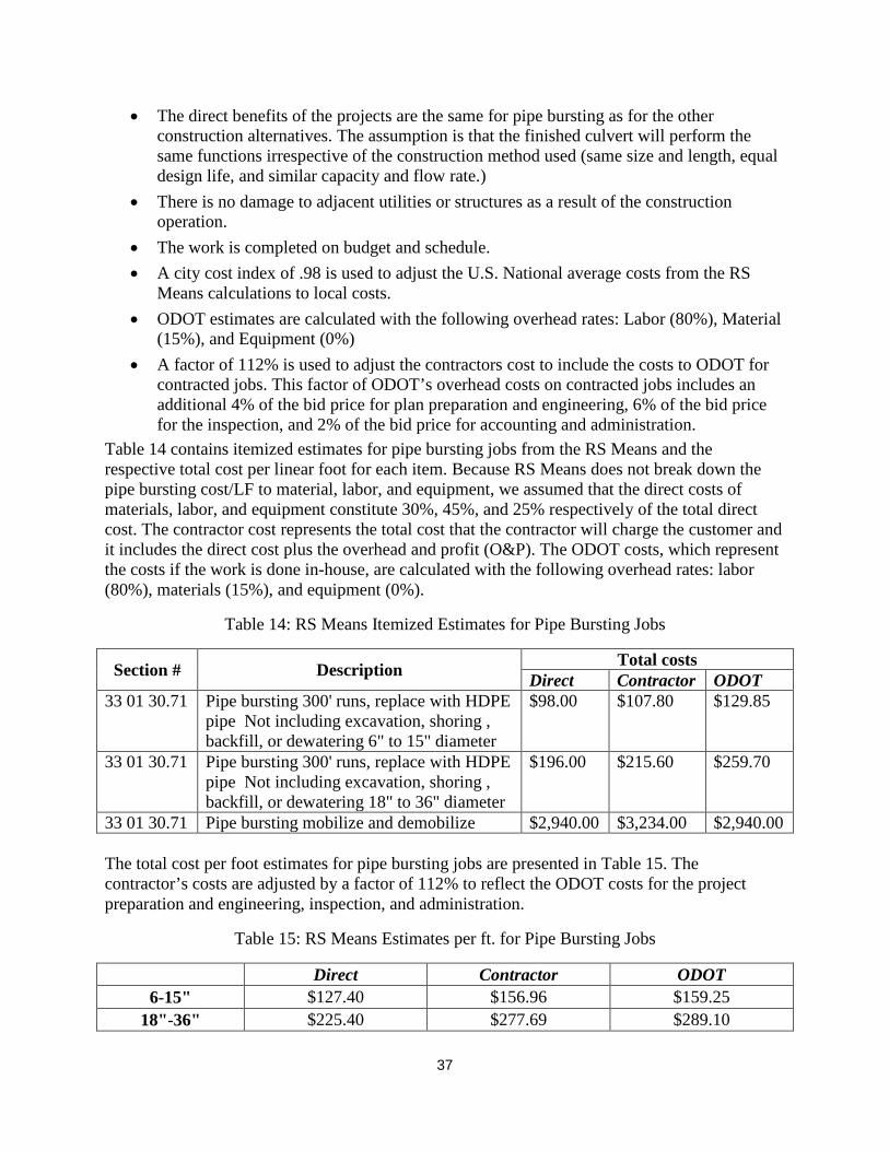
37
• The direct benefits of the projects are the same for pipe bursting as for the other construction alternatives. The assumption is that the finished culvert will perform the same functions irrespective of the construction method used (same size and length, equal design life, and similar capacity and flow rate.)
• There is no damage to adjacent utilities or structures as a result of the construction operation.
• The work is completed on budget and schedule. • A city cost index of .98 is used to adjust the U.S. National average costs from the RS
Means calculations to local costs. • ODOT estimates are calculated with the following overhead rates: Labor (80%), Material
(15%), and Equipment (0%) • A factor of 112% is used to adjust the contractors cost to include the costs to ODOT for
contracted jobs. This factor of ODOT’s overhead costs on contracted jobs includes an additional 4% of the bid price for plan preparation and engineering, 6% of the bid price for the inspection, and 2% of the bid price for accounting and administration.
Table 14 contains itemized estimates for pipe bursting jobs from the RS Means and the respective total cost per linear foot for each item. Because RS Means does not break down the pipe bursting cost/LF to material, labor, and equipment, we assumed that the direct costs of materials, labor, and equipment constitute 30%, 45%, and 25% respectively of the total direct cost. The contractor cost represents the total cost that the contractor will charge the customer and it includes the direct cost plus the overhead and profit (O&P). The ODOT costs, which represent the costs if the work is done in-house, are calculated with the following overhead rates: labor (80%), materials (15%), and equipment (0%).
Table 14: RS Means Itemized Estimates for Pipe Bursting Jobs
Section # Description Total costs Direct Contractor ODOT
33 01 30.71 Pipe bursting 300' runs, replace with HDPE pipe Not including excavation, shoring , backfill, or dewatering 6" to 15" diameter
$98.00 $107.80 $129.85
33 01 30.71 Pipe bursting 300' runs, replace with HDPE pipe Not including excavation, shoring , backfill, or dewatering 18" to 36" diameter
$196.00 $215.60 $259.70
33 01 30.71 Pipe bursting mobilize and demobilize $2,940.00 $3,234.00 $2,940.00 The total cost per foot estimates for pipe bursting jobs are presented in Table 15. The contractor’s costs are adjusted by a factor of 112% to reflect the ODOT costs for the project preparation and engineering, inspection, and administration.
Table 15: RS Means Estimates per ft. for Pipe Bursting Jobs
Direct Contractor ODOT 6-15" $127.40 $156.96 $159.25
18"-36" $225.40 $277.69 $289.10

38
For very shallow culverts, using pipe bursting may lead to damage on the surface because of the displaced soil during the bursting operation. In such cases, this may not be the best alternative. If the depth is considerable, pipe bursting will be the more economically attractive alternative.
ESTIMATE FOR PIPE BURSTING AND RAMMING TESTS For this study, the research team has proposed four test sites. Two of the selected culverts will be burst and the other two will be replaced by pipe ramming. The same bursting head will be used to ram the casing over the existing culvert; ODOT will then extract the old culvert and install a liner in its place. It is important that the selected culverts be low risk and low impact culverts; if the bursting/ramming operation fails, no significant impact will occur. These culverts should be in locations where we could use open-cut successfully with minimal cost implications. The ODOT crew should be ready to open-cut the area and replace the culvert should this eventuate. At least two of the four culverts should be made of corrugated pipe which is challenging to burst and has often proved impossible to go through. These tests will allow us to assess a few modifications to the bursting/ramming system to solve the problem.
The budget in Appendix 2 contains an estimate of the anticipated cost for these four culvert replacement jobs. Based on the pipe bursting manufacturer’s equipment operation manual, the required compressor must have a minimum 1236 CFM for ramming operations up to 30”. The pipes to be burst were assumed to be 18” and they are to be replaced size for size or upsized to 24” HDPE SDR 17. For the Ramming operations, the casing to be used will be 18” steel casings with ½” wall thickness. This will swallow (consume) any culverts with a smaller OD than the 18” casing.
ODOT CONTRIBUTION TO PB AND PR TESTS
• ODOT will identify four (4) low risk culverts to be replaced. Two by pipe bursting (preferably 18” diameter or smaller) and two by pipe ramming (preferably 24” diameter or smaller). These culverts must be deeper than 10 times the outside diameter of the pipe to avoid surface disturbance.
• ODOT will provide the information such as the geotechnical conditions, ground water table level, underground utilities, size of culvert, traffic volume of on field test site locations to the research team. It is standard operating procedures that geotechnical investigation will be conducted prior to any bursting operation-to the extent possible. The depth of the investigations depends on already available information, magnitude of soil variation, and construction risks at this particular site. The research team will work ODOT personnel to determine the appropriate level of information needed.
• ODOT personnel will prepare the pits for the pipe bursting and pipe ramming operations following the specifications provided by the research team and the equipment manufacturers.
• ODOT will provide traffic control and other assistance that may be required for the bursting and ramming operations.
• ODOT will provide the labor, equipment and supplies for welding the Steel Casing, fusion of HDPE, grouting the annular space, and fuel for the compressor.

39
• ODOT will provide the research team with cost of all labor, equipment and supplies, from ODOT’s side, that were incurred in the pipe bursting and ramming operations to enable the research team estimate the actual total cost.
• If any of the bursting/ramming operations fail, ODOT will complete the installations using open cut.
CONTRIBUTION FROM MANUFACTURERS
• TT Technologies and Earth tool will provide the pipe bursting and ramming systems required for the four culvert replacements
• TT Technologies and Earth tool will provide one or two technicians to guide the boring and bursting operations and serve as a teacher/trainer for the ODOT personnel.
CONCLUSIONS AND RECOMMENDATIONS The research team attended the startup meeting and presented an overview of the trenchless techniques that are available in the market place and that can be used to replace or line culverts. Following the presentation, ODOT asked BGSU to investigate the additional cost for incorporating pipe bursting and pipe ramming tests to the scope of work for the project.
This interim report of the project presents the costs of installations using the methods under study, a proposed ABM for phase 2 (complete with specifications and costs), additional information related to pipe bursting, cost estimates from literature and RS Means, an estimate for the cost of the expanded scope (PB and PR tests), and recommendations on how ODOT should proceed.
Horizontal Auger Boring Based on the literature review, installing a 16” waterline underneath I-75 in Bowling Green, Ohio, costs $604.50, $134.50, and $173.44 per linear foot when installed using Auger Boring, Horizontal Directional Drilling, and Open-Cut with detouring traffic, respectively. For auger boring, the costs were estimated to be about $200 per linear foot for a pipe 18 inches in diameter to $1,000 per linear foot for a pipe 60 inches in diameter.
The research team solicited and obtained sample relevant historical bid prices of the methodologies under study from ODOT. The analysis of the limited sample of bid prices that we got from ODOT indicate that the average auger-boring-cost for a ten feet deep culvert was $269.43, $341.86, and $414.28/LF for a 24”, 36”, and 48” culvert respectively. The average open-cut-cost for a ten feet deep culvert was $130.97, $193.90, and $256.83 for a 24”, 36”, and 48” culvert respectively. The comparison of the auger boring cost per foot from bid prices of the small number of projects versus the cost from the RS Means indicates that the contractor’s cost is less than that of ODOT. However, this comparison is unreliable due the small number of bid prices and the insufficient information about the scope of work and the respective prices.
The research team conducted preliminary cost estimates using RS Means. The estimates indicate that the cost per foot for 24", 36", and 48" are $538.72, $816.10, and $1,059.29 respectively for horizontal auger boring method using a contractor. Because the overhead structure for ODOT is different in its structure than with a contractor, the estimated cost for the same diameters using the ODOT workforce are $508.60, $768.86, and $1002.15/ LF respectively. The RS Means

40
estimates also indicate that the cost per foot for 24", 36", and 48" are $153.26, $205.24, and $254.47 respectively for the open-cut method using a contractor. The estimated cost for the same diameters using ODOT’s workforce are $147.89, $199.02, and $245.91 / LF respectively. This analysis indicates that doing the job in-house costs less than contracting. It is a more accurate assessment of the two competing alternatives because we are using RS Means for both alternatives.
The final analysis indicated that the ownership and operation cost of an ABM to the contractor is around $165/hr. and the cost for ODOT to own and operate the ABM is around $110/hr. It is also clear that the more hours per year that the equipment is in operation, the lower the cost per hour to ODOT. The number of culverts in the State of Ohio indicates that the auger boring crew can be in operation for more days per year than the assumed 75 days/year (20%); the ownership cost can be cut in half if the number of operational days doubles to 150 days/year. The lower cost of capital advantage for ODOT offers another significant competitive advantage. We can deduce, from this analysis, that it would be more economical for ODOT to do the work in-house than to contract.
Generally using ODOT’s work force to replace culverts provides ODOT with more control over the design and construction, which can reduce overall cost and time. It allows higher ability and faster decision making to deal with unforeseen conditions because both the construction crew and owner representative are ODOT employees. The ODOT construction crew can start work with partial design and ground information since the construction crew will adjust and adapt to the encountered conditions.
On the other hand, hiring an Engineering firm to design the project and a contracting firm to install the conduit is more appropriate when the risk is high and the ground conditions are unfavorable. They are better positioned to deal with these challenging conditions because they are specialized in these types of work and do it on a daily basis. Small specialty contractors often times have smaller overhead expenses than a large organization like ODOT. Further discussion of these issues will be explored in Phase 2 of the project.
We recommend purchasing the ABM for the following reasons:
• Two of the three above cited cost comparisons indicate that it will be more economical for ODOT to purchase and operate the ABM.
• Doing HAB work in house provides higher level of flexibility in the work such as allowing design and construction works to overlap, lesser disputes, and no bidding cost.
• The ABM will provide an additional tool to replace old deteriorated culverts across the State of Ohio.
• Based on literature, there are conditions that favor the use of horizontal auger boring over the conventional open-cut method.
• The ABM will provide ODOT’s construction crew valuable training and development in the advanced technologies of replacing culverts.

41
Pipe Bursting and Pipe Ramming Research Tests Based on literature review, the cost savings, in favorable conditions for pipe bursting, could amount to more than 10 to 15%. Another collection of bid price data indicates that the cost of a 24” pipe replacement size for size ranges from $90 to $255/LF. For another 18” pipe replacement size to size, the bursting cost was $242/LF and the open cut cost was $343. A research conducted for the U.S. Department of Agriculture (USDA) Forest Service roadway culvert applications concluded that the cost of replacing or rehabilitating culverts 18 inches in diameter (size for size) using pipe bursting are estimated to vary from $100 to $200 per linear foot, and for 48-inch-diameter pipes, the cost was $850 per linear foot
It is recommended to use pipe bursting for only deep installations to avoid surface disturbance due to ground movements. The preferred condition for pipe bursting is when the old conduit is made of rigid material with compressible soil (such as trench backfill) around the pipe. It is also recommended that a specialized contractor in pipe bursting do bursting work for conduits larger than 24” in diameter.
The expanded scope of work will increase the cost to ODOT by $71,273.22 as shown in Table 16, but due to the cost savings of $60,000 for the auger boring equipment, the net cost increase will be $11,274. The project duration will increase by four month due to the expansion. The supplies item of $38,995.00 covers the steel pipe, HDPE pipe, the freight expenses for bursting equipment, and the rental cost for the required compressor. The remaining amount is the additional cost for the training and productivity study for the four additional site visits, and the stipend and fringe benefits for the student workers for the additional four months of work. Details of the expanded scope schedule and budget is shown in Appendix 2.
Table 16: The Original Proposal Cost, Expanded Scope Proposal, and the Difference
Budget Category Original Proposal Original + PB tests PB tests only Salaries & Wages $76,012.64 $95,299.28 $19,286.64 Fringe Benefits $16,930.95 $20,466.74 $3,535.79 Travel $7,240.00 $9,174.00 $1,934.00 Supplies $- $38,995.00 $38,995.00 Equipment $300,000.00 $240,000.00 $(60,000.00) Printing $500.00 $500.00 $- Indirect Costs $29,644.93 $37,166.72 $7,521.79 Total $430,328.52 $441,601.74 $11,273.22 We recommend expanding the scope of the project for the following reasons:
• The labor and equipment cost for replacing these additional test culverts will be greatly leveraged because the manufacturers will do the operations themselves
• The expanded scope will provide the required information to make a decision on whether ODOT would benefit from acquiring the bursting system in the future for its in-house operations.

42
• The expanded scope will provide ODOT’s construction crew valuable training and development in the advanced technologies of replacing culverts.
• The additional expenses for this expansion are costs that ODOT will still incur when replacing these culverts and the research team anticipates cost savings as a result these tests.
• The expanded scope creates a win-win for ODOT and the manufacturers, and will serve as a contribution to development in the trenchless construction industry where bursting corrugated pipes is an outstanding problem.
REFERENCES Australasian Society for Trenchless Technology. (2010). Installation of New Pipelines. Retrieved
from Installation of New Pipelines: http://www.astt.com.au/trenchless_technology/new_installations/
Ariaratnam, S. T., & Hahn, U.-H. (2007). Simplified model for numerical calculation of pull forces in static pipe-bursting operations. Tunnelling and Underground Space Technology, 644–654.
Atalah, A. (1991). Pipe Jacking Design and Construction. Ruston, LA: Louisiana Tech University.
Atalah, A. (1996). Design of Microtunneling and Jacking Pipe. ASCE Specialty Conference-Pipeline Crossings 1996. Burlington, VT: ASCE.
Atalah, A. (2001). Cost Comparison Between Open Cut Construction and Pipe Bursting for the Repair of Tripler Army Medical Center Sewer Line Project. North American NO-DIG 2001. Nashville, TN.: Annual Conference of the North American Society of Trenchless Technology.
Atalah, A. (2006). Safe Distance between Large-Diameter Rock Pipe Bursting and Nearby Buildings and Burried Structures. Journal of Transportation Engineering, 350-356.
Atalah, A. (2006). The Safe Distance between Large-Diameter Rock Pipe Bursting and Nearby Buildings and Buried Structures. ASCE Journal of Transportation Engineering.
Atalah, A. (2007). The need for Trenchless Replacement Techniques in the Developing Countries. North American NO-DIG 07. San Diego, CA: North American Society of Trenchless Technology.
Atalah, A., Sterling, R. S., Hadala, P., & Akl, F. (1998). The Effect of Pipe Bursting on Nearby Utilities, Pavement and Structures - TTC book #TTC-98-01. Ruston, LA: Louisiana Tech University.
Boyce, G. M., & Bried, E. M. (1994). Estimating the social cost savings of trenchless techniques. No-Dig Engineering,, 1(2), 2-5.
Budhu, G., & Iseley, D. T. (1994). The Economics of Trenchless Technology Versus the Traditional Cut and Fill in High-Activity Urban Corridors-A Research Concept in a Real
43
World Environment. NO-DIG 94, Annual Conference of the North American Society of Trenchless Technology. Dallas, TX: North American Society of Trenchless Technology.
Camp, C., Boyce, G., & Tenbusch, A. (2010). Culvert Replacement Using Pipe Ramming, Tunneling, and Pipe Jacking. North American Society for Trenchless Technology (NASTT) No-Dig Show 2010, (pp. Paper A-5-05). Chicago, Illinois.
Center for Underground Infrastructure Research and Education. (2004). Horizontal Auger Boring Projects - ASCE manuals and reports on engineering practice; no. 106. Roston, VA: American Society of Civil Engineers.
Gangavarapu, B. S., Najafi, M., & Salem, O. (2003). Quantitative analysis and comparison of traffic disruption using open-cut and trenchless methods of pipe installation. ASCE International Conference on Pipeline Engineering and Construction: New Pipeline Technologies, Security, and Safety (pp. 1714-1724). Baltimore, MD, United states: American Society of Civil Engineers Texas Section.
Goduto, V., & Atalah, A. (2013). The Design and Construction Cost of a Water Line underneath I-75 in Bowling Green, OH. NO-DIG 13 Conference (pp. TM1-T6-02). Sacramento, CA: North American Society of Trenchless Technology.
Hollingshead, T., & Tullis, B. P. (2009). In-Situ Culvert Rehabilitation: Synthesis Study and Field Evaluation; report No. UT-07.204. Salt Lake, UT: Utah Department of Transportation.
International Society for Trenchless Technology. (2013). Glossary. Retrieved 2013, from http://www.istt.com/glossary?letter=M
Iseley, T., & Gokhale, S. (1997). Trenchless installation of conduits beneath roadways - NCHRP Synthesis 242. Washington, D.C.: Transportation Research Board/National Research Council.
Lee, H., Najafi, M., & Matthys, J. (2007). Cost comparison of pipeline asset replacement: open-cut and pipe bursting. ASCE International Pipeline 2007 Conference (pp. 1-11). Boston, MA: American Society of Civil Engineers.
Najafi, M. (2013). Trenchless Technology: Planning, Equipment, and Methods. New York: McGraw-Hill Companies, Inc.
Najafi, M. (2013). Trenchless Technology: Planning, Equipment, and Methods. New York: McGraw-Hill Companies, Inc.
Najafi, M., & Kim, K. O. (2004). Life-cycle-cost comparison of trenchless and conventional open-cut pipeline construction projects. ASCE Pipeline Division Specialty Congress-Pipeline Engineering and Construction (pp. 635-640). San Diego, California: ASCE Pipeline Division.
Nickol Boring Inc. (2013). Auger Boring Machine. Retrieved from Nickol Boring Inc.: http://www.nickolboring.com/specifications.html

44
North American Society for Trenchless Technology. (2013, September 15). Glossary of Terms and Definitions. Retrieved from North American Society for Trenchless Technology: http://www.nastt.org/glossary/T?page=2
Ohio Department of Transportation. (2012). Ohio Department of Transportation Culvert Management Manual. Columbus, OH: Ohio Department of Transportation.
Ohio Department of Transportation. (2014, January). 603 Pipe Culverts, Sewers, and Drains. Retrieved from Ohio Department of Transportation: http://www.dot.state.oh.us/Divisions/ConstructionMgt/OnlineDocs/2009MOP/600%20Incidentals/603/603%20Pipe%20Culverts.htm
Ohio Research Institute for Transportation and the Environment (ORITE). (2005). Risk Assessment and Update of Inspection Procedures for Culverts. Columbus OH: Ohio Department of Transportation.
Orton, C. (2010). Pipe Ramming For Oil And Gas Pipeline Applications. North American Society for Trenchless Technology (NASTT) No-Dig Show 2010 (pp. Paper A-5-04 ). Chicago, Illinois: North American Society for Trenchless Technology (NASTT).
Piehl, R. (2005). Summary of trenchless technology for use with USDA Forest Service culverts. . Eugene, Oregon: US Department of Agriculture, Forest Service, Technology & Development Program.
Plastic Pipe Institute. (2008). Chapter 16- Pipe Bursting. In P. P. Institute, Handbook of Polyethylene Pipe-Second Edition. Irving, TX: Plastic Pipe Institute.
Purdue University. (2010). AUGER BORING. Retrieved from Trenchless Technology: http://rebar.ecn..edu/Trenchless/secondpage/Content/AB.htm
Read, G. F. (2004). Sewers: Replacement and New Construction. Butterworth-Heinemann.
Rehan, R., & Knight, M. (2007). Do Trenchless Pipeline Construction Methods Reduce Greenhouse Gas Emissions? Waterloo, Ontario: University of Waterloo.
Salem, O., Najafi, M., Salman, B., D. C., Patil, R., & Bhattachar, a. D. (2008). Use of Trenchless Technologies for a Comprehensive Asset Management of Culverts and Drainage Structures. Madison, WI: Midwest Regional University Transportation Center.
Simicevic, J., & Sterling., R. L. (2001). Guidelines for pipe bursting. Vicksburg, MS: US Army Corps of Engineers, Engineering Research and Development Center (ERDC).
The International Pipe Bursting Association. (2012). Guideline for Pipe Bursting. Owing Mills, MD: The International Pipe Bursting Association (IPBA).
The International Society for Trenchless Technology. (2013). Auger Boring. Retrieved from The International Society for Trenchless Technology: http://www.istt.com/guidelines/auger-boring

45
The International Society for Trenchless Technology. (2013). Glossary. Retrieved from The International Society for Trenchless Technology: http://www.istt.com/glossary?letter=P
Thomson, J., Sangster, T., & Kramer, S. (1998). An overview of the economics of trenchless technology. NO DIG ENGINEERING,, 5, 23-27.
Timberlake, M. (2011). Pipe Bursting Various Types Of Pipes. Underground Construction, 66(6), pp. 42-43.
TT Technologies. (2004). Groundoburst Static Pipe Bursting System. Retrieved from TT Technologies, Inc.: http://www.tttechnologies.com/literature/Grundoburst%20Lit.pdf