evaluation of erlang for a stigmergy holonic routing
TRANSCRIPT

Evaluation of Erlang for a stigmergy holonic
routing controller
by
Christopher Sean van den Berg
March 2018
Thesis presented in partial fulfilment of the requirements for the degree
of Master of Engineering Mechatronics in the Faculty of Engineering at
Stellenbosch University
Supervisor: Prof AH Basson

DECLARATION
By submitting this thesis electronically, I declare that the entirety of the work contained therein is my own, original work, that I am the sole author thereof (save to the extent explicitly otherwise stated), that reproduction and publication thereof by Stellenbosch University will not infringe any third party rights and that I have not previously in its entirety or in part submitted it for obtaining any qualification.
March 2018
Copyright © 2018 Stellenbosch University All rights reserved
Stellenbosch University https://scholar.sun.ac.za

iii
ABSTRACT
A reconfigurable manufacturing system (RMS) is a manufacturing paradigm aimed to be able to react to manufacturing uncertainty caused by hardware failures and changes in the global market. Transport systems for RMSs should be able to easily adapt the routing of parts between manufacturing stations, while making optimal use of the transport infrastructure to maximise the RMS's throughput. In this thesis, a holonic routing controller with stigmergy, aimed at a palletised conveyor for an RMS, is developed using Erlang. The objective is to evaluate the suitability of Erlang in implementing a holonic control architecture where a large number of concurrent processes is required within one controller.
The routing controller is adapted from architectures found in literature, and uses elements from the product, resource, order, staff architecture (PROSA). The routing controller is a conveyor controller that transfers a pallet from a source to a destination within the conveyor system based on an instruction given by an outside source, such as a user. The conveyor controller makes use of order, resource, feasibility and ant holons to perform the pallet transfer. Order, feasibility and ant holons were each implemented in their own Erlang process within the conveyor controller, while resource holons used three Erlang processes.
The conveyor controller was tested in the Mechatronics, Design and Automation Research Group (MADRG) at Stellenbosch University. Higher-level control was performed by interfacing the conveyor controller, described in this thesis, with previously developed lower-level controllers. The results of the testing proved that the controller possessed all the required characteristics of an RMS and could successfully manage pallet traffic within the conveyor system, including avoiding bottlenecks and changing a previously decided route when conveyor segments unexpectedly become available or unavailable.
It was found that Erlang is an appropriate programming language to use in implementing the conveyor controller. Erlang possesses built-in functionality that was found to be convenient and useful. With Erlang, it was possible to create and run processes with ease, even when the system was running.
Stellenbosch University https://scholar.sun.ac.za

iv
UITTREKSEL
'n Herkonfigureerbare-vervaardigingsstelsel (HVS) is 'n vervaardigingsparadigma wat daarop gemik is om te reageer op die vervaardigingsonsekerheid wat veroorsaak word deur hardewarefalings en veranderinge in die globale mark. Vervoerstelsels vir HVS'e moet die roete van onderdele tussen vervaardigingsstasies maklik kan aanpas, terwyl die vervoerinfrastruktuur optimaal benut word om die HVS se deurset te maksimeer. In hierdie tesis word 'n holoniese roeteringsbeheerder met "stigmergy", gemik op 'n vervoerband met pallette vir 'n HVS, ontwikkel met behulp van Erlang. Die doel is om die geskiktheid van Erlang te evalueer in die implementering van 'n holoniese beheerargitektuur waar 'n groot aantal gelyktydige prosesse binne een beheerder benodig word.
Die roeteringsbeheerder is 'n aanpassing van argitekture wat in die literatuur voorkom, en gebruik elemente van die produk-hulpbron-bestelling-hulp-argitektuur (PROSA). Die roeteringsbeheerder is 'n voerbandbeheerder wat 'n pallet van 'n beginpunt na 'n bestemming binne die vervoerstelsel neem, gebaseer op 'n instruksie wat deur 'n buite-bron, soos 'n gebruiker, gegee word. Die voerbandbeheerder maak gebruik van bestelling-, hulpbron-, haalbaarheid- en mier-holons om die palet-oordrag uit te voer. Bestelling-, haalbaarheid- en mier-holons is elk in hul eie Erlang proses geïmplementeer binne die voerbandbeheerder, terwyl hulpbron-holons drie Erlang prosesse gebruik het.
Die voerbandbeheerder is in die “Mechatronics, Design and Automation Research Group” (MADRG) aan die Universiteit Stellenbosch getoets. Hoërvlakbeheer is uitgevoer deur die voerbandbeheerder, wat in hierdie tesis beskryf word, te verbind met voorheen ontwikkelde laer-vlak beheerders. Die resultate van die toetse het bewys dat die beheerder al die vereiste eienskappe van 'n HVS besit en suksesvol palletverkeer binne die vervoerstelsel kon bestuur, insluitende die vermy van bottelnekke en die verandering van 'n voorheen bepaalde roete wanneer vervoerband-segmente onverwags beskikbaar of onbeskikbaar raak.
Daar is bevind dat Erlang 'n gepaste programmeringstaal is om te gebruik in die implementering van die voerbandbeheerder. Erlang beskik oor ingeboude funksionaliteit wat gerieflik en nuttig is. Met Erlang was dit moontlik om prosesse met gemak te skep en te loop, selfs wanneer die stelsel aan die gang was.
Stellenbosch University https://scholar.sun.ac.za

v
ACKNOWLEDGEMENTS
Firstly I would like to thank Prof. A.H. Basson for your continued guidance, and being readily available. Your vast knowledge assisted in not only solving problems, but has deepened my interest in the field of mechatronics. Next, I’d like to thank fellow research group members M.M. Deacon and C.S. van den Bergh for providing the pleasant working environment, and K. Kruger and R. Rodrigues for the experience and knowledge shared. Lastly I’d like to thank my family and friends for whom I am so grateful for providing me with a sound support basis for completing this journey.
Stellenbosch University https://scholar.sun.ac.za

vi
TABLE OF CONTENTS
Page
Declaration.................................................................................................................................... i
Abstract ....................................................................................................................................... iii
Uittreksel ..................................................................................................................................... iv
Acknowledgements .................................................................................................................. v
Table of contents ...................................................................................................................... vi
List of figures ............................................................................................................................. xi
List of tables ............................................................................................................................ xiii
Nomenclature ......................................................................................................................... xiv
1 Introduction ..................................................................................................................... 1
1.1 Background ......................................................................................... 1
1.2 Objectives and scope .......................................................................... 3
1.3 Motivation .......................................................................................... 4
1.4 Thesis overview .................................................................................. 5
2 Literature review ........................................................................................................... 6
2.1 Classification of manufacturing systems ............................................ 6
2.1.1 Classic manufacturing paradigms ...................................... 6
2.1.2 Reconfigurable manufacturing systems ............................. 6
2.2 Manufacturing control architectures ................................................... 8
2.2.1 Centralized control architectures ....................................... 9
2.2.2 Hierarchical control architectures ...................................... 9
2.2.3 Heterarchical control architectures .................................... 9
Stellenbosch University https://scholar.sun.ac.za

vii
2.2.4 Holonic control architectures ........................................... 10
2.3 PROSA: A holonic manufacturing system architecture ................... 10
2.4 Multi-agent control using PROSA and stigmergy ............................ 12
2.4.1 Role of PROSA and holon communication ..................... 12
2.4.2 Information propagation .................................................. 13
2.4.3 Additional responsibilities of resource and order holons . 17
2.5 Pallet routing optimization using simulation .................................... 18
2.6 Erlang-based control in reconfigurable manufacturing systems ...... 20
3 Architecture .................................................................................................................. 22
3.1 Application context .......................................................................... 22
3.2 Conveyor controller architecture ...................................................... 23
3.3 Blackboard information format ........................................................ 25
3.4 Route selection ................................................................................. 26
3.5 Architecture adaptations ................................................................... 27
4 Implementation ........................................................................................................... 28
4.1 Overview .......................................................................................... 28
4.2 Resource holon ................................................................................. 29
4.2.1 Structure of the resource holon ........................................ 29
4.2.2 Blackboard manager ........................................................ 29
4.2.3 Feasibility holons ............................................................. 30
4.2.4 Higher-level communication manager ............................. 35
4.2.5 Lower-level communication manager ............................. 36
4.3 Junction resource holon .................................................................... 38
Stellenbosch University https://scholar.sun.ac.za

viii
4.3.1 Overview .......................................................................... 38
4.3.2 Blackboard manager ........................................................ 38
4.3.3 Higher-level communications manager ........................... 39
4.3.4 Lower-level communications manager ............................ 41
4.4 Transportation manager .................................................................... 41
4.5 Order holon ....................................................................................... 41
4.5.1 Structure of the order holon ............................................. 42
4.5.2 The “route selection” states .............................................. 45
4.5.3 Order exploration ant holons............................................ 47
4.5.4 Order intention ant holons................................................ 49
5 Evaluation ...................................................................................................................... 53
5.1 Overview .......................................................................................... 53
5.2 Experiment: obtaining travel times and queue capacities within the
conveyer system ............................................................................... 54
5.2.1 Objective: ......................................................................... 54
5.2.2 Experimental procedure ................................................... 54
5.2.3 Results .............................................................................. 54
5.2.4 Repeatability .................................................................... 57
5.3 Experiment: Diagnosability test ....................................................... 57
5.3.1 Objective .......................................................................... 57
5.3.2 Experimental procedure ................................................... 57
5.3.3 Results .............................................................................. 58
5.3.4 Interpretation of results .................................................... 58
5.4 Experiment: Route selection test ...................................................... 58
Stellenbosch University https://scholar.sun.ac.za

ix
5.4.1 Objective .......................................................................... 58
5.4.2 Experimental procedure ................................................... 58
5.4.3 Results .............................................................................. 59
5.4.4 Interpretation of results .................................................... 59
5.5 Experiment: Dampening mechanisms and integrability ................... 60
5.5.1 Objective .......................................................................... 60
5.5.2 Experimental procedure ................................................... 60
5.5.3 Results .............................................................................. 60
5.5.4 Interpretation of results .................................................... 61
5.6 Experiment: Junction node test......................................................... 61
5.6.1 Objective .......................................................................... 61
5.6.2 Experimental procedure ................................................... 61
5.6.3 Results .............................................................................. 61
5.6.4 Interpretation of results .................................................... 62
5.7 Experiment: Customizability and scalability .................................... 62
5.7.1 Objective .......................................................................... 62
5.7.2 Experimental procedure ................................................... 62
5.7.3 Results .............................................................................. 62
5.7.4 Interpretation of results .................................................... 62
5.8 Evaluation of Erlang ......................................................................... 63
6 Conclusion and recommendations ....................................................................... 65
References ................................................................................................................................. 67
Appendix A: Commands to LLC ........................................................................................ 70
Stellenbosch University https://scholar.sun.ac.za

x
PLC 1, 2 and 5: Lifting unit 1, 2 and 3 ......................................................... 70
PLC 3: Lifting unit with a transverse conveyor ........................................... 71
PLC 4: Divert module .................................................................................. 72
PLC 6: Traverse conveyor with pallet magazine ......................................... 73
Appendix B: Controller code .............................................................................................. 75
B.1 Order holon state machine ..................................................................... 75
B.2 Intention ant ........................................................................................... 80
B.3 Resource holon blackboard manager ..................................................... 85
B.4 Junction resource holon ......................................................................... 86
Stellenbosch University https://scholar.sun.ac.za

xi
LIST OF FIGURES
Page
Figure 1: Conveyor used for hardware testing ......................................................... 4
Figure 2: Comparison of 3 types of manufacturing systems with cost vs capacity
Koren (2006:33) ....................................................................................................... 7
Figure 3: Structure of centralized, hierarchical and heterarchical control
architectures (Kotzé, 2016) ...................................................................................... 8
Figure 4: Information exchange within a PROSA (Van Brussel et al., 1998). ...... 12
Figure 5: Propagation of the subnet capability layer of product P1 (Hadeli et al.,
2004) ...................................................................................................................... 14
Figure 6: Propagation of the transportation time layer from resource 7 (Hadeli et
al., 2004) ................................................................................................................ 16
Figure 7: Propagation of the Schedule list from resource 4 (Hadeli et al., 2004) . 17
Figure 8: Optimization strategy using the “Virtual holonic controller approach”
(Havenga, 2017) ..................................................................................................... 19
Figure 9: Optimization strategy using the “Simio controller approach” (Havenga,
2017) ...................................................................................................................... 19
Figure 10: Internal Architecture of Resource Holon (Kruger & Basson, 2014) .... 21
Figure 11: Positions of a node and a junction node ............................................... 22
Figure 12: Photograph of a lifting unit of the conveyor system adapted from Kotzé
(2016) ..................................................................................................................... 23
Figure 13: Holarchy of the conveyor controller .................................................... 23
Figure 14: Structure of a regular resource holon and junction resource holon ...... 29
Figure 15: Flow diagram of the expiration check function ................................... 31
Figure 16: Propagation of the 1st layer ................................................................... 32
Figure 17: Feasibility holon program flow diagram .............................................. 34
Stellenbosch University https://scholar.sun.ac.za

xii
Figure 18: Flow diagram of the time generator function ....................................... 37
Figure 19: Flow diagram of entry handling function ............................................. 38
Figure 20: Flow diagram of the timer generator for a junction resource holon ..... 40
Figure 21: State diagram of the order holon .......................................................... 45
Figure 22: Flow diagram of the route selection process ........................................ 46
Figure 23: Example of an exploration ant preforming its protocol ....................... 48
Figure 24: Flow diagram of exploration ant holon ................................................ 49
Figure 25: Flow diagram of an intention holon ..................................................... 52
Figure 26: Conveyer Setup in laboratory ............................................................... 53
Figure 27: Conveyor used for hardware testing ..................................................... 54
Figure 28: Cropped screenshot of console before turning off R5 .......................... 58
Figure 29: Cropped screenshot of console after turning off R5 ............................ 58
Figure 30: Edited screenshot of the console before turning on R5 ........................ 60
Figure 31: Edited screenshot of the console after turning on R5 ........................... 60
Figure 32: Placement of conveyor modules (Kotzé, 2016) ................................... 70
Figure 33: Lifting unit module (Kotzé, 2016) ....................................................... 71
Figure 34: Lifting unit with transverse conveyor (Kotzé, 2016) ........................... 72
Figure 35: Divert module ....................................................................................... 73
Figure 36: Traverse conveyor with pallet magazine .............................................. 74
Stellenbosch University https://scholar.sun.ac.za

xiii
LIST OF TABLES
Page
Table 1: Summary of definitions used in a holonic manufacturing system ........... 10
Table 2: Example of information in first layer ...................................................... 25
Table 3: Example of information in second layer .................................................. 26
Table 4: Example of conveyer map format ........................................................... 28
Table 5: List and requests and the responses for a resource holon ........................ 35
Table 6: Description of "receive" clauses in the transportation manager .............. 42
Table 7: Format of bookings made by the intention ant holon .............................. 50
Table 8: Time taken to travel between nodes and across junctions ....................... 56
Table 9: Queuing capacity at each node ................................................................ 57
Table 10: Travel times and path selected for the route selection test .................... 59
Table 11: start and end times for the junction node test ........................................ 62
Table 12: Available commands for the lifting unit ................................................ 71
Table 13: Available commands for the divert module .......................................... 73
Table 14: Available commands for the transverse module with pallet magazine . 74
Stellenbosch University https://scholar.sun.ac.za

xiv
NOMENCLATURE
AVG - Autonomous guided vehicles
CNC - Computer numerically controlled machines
DML - Dedicated manufacturing line
ETS - Erlang Term Storage
FMS - Flexible Manufacturing System
HLC - High-level control
HMS - Holonic manufacturing system
LLC - Low-level control
MADRG - Design and Automation Research Group
MAS - Multi-agent systems
PLC - Programmable logic computer
PROSA - Product-resource-order-staff architecture
RMS - Reconfigurable manufacturing system
Stellenbosch University https://scholar.sun.ac.za

1
1 INTRODUCTION
1.1 Background
Manufacturers are seeking fast and cost-effective solutions to meet customer demands. Consumer markets are becoming increasingly difficult to supply due to the following marketing challenges:
• Product demand is seasonal and fluctuates over time.
• Products’ life cycles are becoming increasingly shorter.
• The number of product variants is increasing.
Classical manufacturing can be classified into two types, i.e. dedicated manufacturing lines (DMLs) and flexible manufacturing systems (FMSs). DMLs are systems that are designed to manufacture a specific product or a core part of a product. DMLs generally have high initial costs, but if used to manufacture products that have a high throughput, the cost per part produced is relatively low. FMSs are designed to be able to create a wide variety of products at a low production capacity. FMSs have a high initial cost and a low throughput and therefore have a high cost per part (Koren, et al., 1999).
Trying to meet the marketing challenges mentioned above using classical types of manufacturing proves to be expensive and slow reacting. DMLs are unable to respond to production volume changes because increasing production capacity requires installation of new lines or to build in additional production capacity at the factory start-up. FMSs are able to react to product changes, but unable to undergo structural changes. FMSs therefore cannot respond to fluctuating demands or major machine failures. A new type of manufacturing is desired that will be able to meet the marketing challenges, since classical types of manufacturing prove to be unsuitable (Koren & Shpitalni, 2010).
Koren et al. (1999) proposed a concept known as RMSs as a possible manufacturing type that could be suitable to meet the marketing challenges. An RMS is a system that is aimed to have the flexibility of an FMS and the high throughput of a DML. RMSs are therefore required to have an adjustable production capacity and can produce any part from a part family.
At the heart of an RMS is a transport system. To allow the manufacture of a variety of products in changing and unpredictable combinations, the transport system should be able to easily adapt the routing of parts between manufacturing stations, while ideally making optimal use of the transport infrastructure to maximise the RMS's throughput. Autonomous guided vehicles (AGVs) and palletised conveyors are two transport systems that can commonly be considered for these situations. This thesis focusses on palletised conveyors, but much of the research here is also applicable to AGVs.
Stellenbosch University https://scholar.sun.ac.za

2
Architectures such as PROSA and ADCOR proposed for RMSs are examples of holonic control. In holonic control, the manufacturing system is modelled as an entity that is a collection of holons. A holon is defined as an autonomous entity that is able to interact with its local environment and other holons to accomplish its own goal. A holon can be broken down into more holons. This structure of holons is known as a holarchy (Giret & Botti, 2004). Holons are robust structures due to individual autonomy and as such are able to endure disturbances in the environment. There are a number of methods suggested to interpret a manufacturing environment as a holonic structure. One method is the PROSA reference architecture (Van Brussel et al., 1998).
The PROSA architecture breaks the manufacturing system into the following types of holons: product, resource, order and staff. PROSA is used since it divides the manufacturing system in such a manner that allows the application of more advanced hybrid-control algorithms (Van Brussel et al., 1998).
The control algorithm determines the manner in which the holons will make decisions within a manufacturing system. A limitation of the PROSA architecture is that the holons, in principle, each makes decisions based on their own "world view" and there is no express provision for a global view. Although this approach aids in robustness, it inherently limits the holonic system's ability to achieve global optima. One application where this limitation has a significant effect is in the control of a conveyor system where multiple pallets can follow different routes between stations. Each pallet would typically be associated with its own holon, but if these holons are not aware of each other, they may all select the seemingly shortest path, leading to congestion and sub-optimal throughput. "Ants" can be added to the PROSA architecture to improve the global performance of such systems.
The ant colony optimization algorithm is derived from the behaviour of food foraging ants, referred to as stigmergy. Ants are autonomous entities that make use of only local information and always drop pheromones along the paths that they walk, which decay over time. Other ants that come across these paths will tend to follow these pheromone scented paths. If no path with a pheromone scent is encountered, the ants will search randomly for a food source. The path with the strongest pheromone scent will be the most frequently travelled path and leads to the best food source (Valckenaers et al., 2002). Stock and Zülch (2012) suggested a method to model ant colony optimization in a manufacturing system.
Holonic controllers have traditionally been implemented as multi-agent systems (MASs) in research contexts. However, MASs have not found general acceptance in manufacturing industries. Furthermore, holonic controllers implemented as MASs use an operating system thread for each holon. When stigmergy is also employed, the resulting large number of operating system threads can place extreme demands on the computer resources. Erlang offers an attractive alternative to MASs, in this respect.
Stellenbosch University https://scholar.sun.ac.za

3
Erlang is a programming language developed by Ericsson and is commonly used in telecommunication applications (Rouse, 2007). Erlang requires less computational resources and requires fewer lines of uncommented code than most other commonly used programming languages. It also allows real-time updates of code and is robust to changes within the software environment. Erlang has extensive libraries that facilitate communication between holons (Kruger & Basson, 2014).
The work done in this thesis in affiliated with the MADRG at Stellenbosch University. Related research in the MADRG into the control of a conveyor that forms part of an RMS started with Le Roux's (2013) hierarchical controller that was based on IEC 61499 function blocks. Kotzé (2016) developed a new distributed controller for the conveyor, to reduce the reconfiguration time substantially. Neither Le Roux's nor Kotzé's controllers attempted to achieve globally optimised throughput. To investigate global optimisation of throughput, Havenga (2017) extended Kotzé's controller. Havenga used a simulation of the conveyor to predict future traffic and thus allow the routing of a pallet to take other pallets' motions into account. Although Havenga showed that his approach was successful, it relied on the creation of a reasonably accurate simulation of the conveyor with estimates of the times that each pallet would remain at the manufacturing stations it visits. This information is often not known to the conveyor controller. The present thesis is therefore investigating an alternative stigmergy-based approach.
The MADRG has also been conducting research into the use of Erlang for implementing holonic manufacturing systems (Kruger & Basson, 2015) and the present thesis contributes towards this research. Other related current research (by G Hawkridge) includes the evaluation of Erlang to achieve controller redundancy.
1.2 Objectives and scope
The objective of this thesis is to develop a controller for a reconfigurable palletised conveyor system, using an architecture based on PROSA and stigmergy, implemented in Erlang. Through this, the suitability of Erlang is evaluated for this type of application.
Therefore, the hypothesis evaluated in this thesis is that a combination of PROSA, stigmergy and Erlang is well suited to develop a controller for a palletized conveyor for a RMS, with consideration of future pallet motions.
The conveyor controller for a reconfigurable palletised conveyor system should have all the characteristics of an RMS, described in section 2.1.2, and must be able to perform route selection for more than two pallets at a time.
The controller must be demonstrated using the conveyor in the MADRG’s laboratory at Stellenbosch University shown in Error! Reference source not found.. An explanation of the conveyer’s components can be found in Appendix A.
Stellenbosch University https://scholar.sun.ac.za

4
Figure 1: Conveyor used for hardware testing
A higher-level controller (HLC) will, in practice, send commands to the conveyor controller. The HLC is not a focus in the present research and a simple HLC is just required for testing the conveyor controller. To control the conveyor hardware during the abovementioned demonstration, the conveyor controller uses the LLCs developed by Kotzé (2016). The conveyor controller must therefore be able to send the required commands to the LLCs, as well as interpret information received from the LLCs.
1.3 Motivation
The work presented in this thesis makes contributions in three respects.
In the first respect, this thesis presents a new approach for the particular type of controller, taking into account the influence of pallets on one another. The only similar work that could be found is that of Havenga (2017), mentioned above in the Background section with its limitations, and that of Hadeli et al. (2004). Hadeli et al. developed an agent-based manufacturing control system, employing PROSA with stigmergy, which is described in detail in Section 2.4. The conveyor controller presented in this thesis includes alterations of Hadeli’s architecture, such as bidirectional paths and pallet queuing. The details of the changes are described in Section 2.5.
The second contribution of the thesis is in the evaluation of Erlang for a stigmergy-based controller. This type of controller requires a large number of threads running within the controller and Erlang is a concurrent programming language that is proficient at running a very large number of threads at the same time (Rouse, 2007). Valckenaars and Van Brussels (2016:45) support the use of Erlang for stigmergy-based controllers and consider it the most-appropriate programming language to use for similar applications; however no previous implementations could be found in literature.
Stellenbosch University https://scholar.sun.ac.za

5
The third contribution is in that much of the work on palletised conveyors presented here can be considered to be applicable to other RMSs as well. The approach developed here to manage a large number of orders to make optimal use of limited manufacturing resources is not restricted to conveyor systems.
1.4 Thesis overview
This section provides a summary of what is in each chapter that follows. Chapter 2 gives a brief description of concepts and architectures used in this thesis, as well as some insight to related research. It explains all the concepts and architectures used. It also outlines all the previous work related to this thesis from MADRG. Chapter 3 describes the architecture of the conveyor controller. Chapter 4 gives describes how the controller was implemented. Chapter 5 provides information of the hardware testing performed and an evaluation of Erlang. The final chapter, Chapter 6, gives a conclusion of the thesis and recommendations of what further work could be done.
Stellenbosch University https://scholar.sun.ac.za

6
2 LITERATURE REVIEW
2.1 Classification of manufacturing systems
2.1.1 Classic manufacturing paradigms
In the manufacturing industry, there are two common types of manufacturing systems in use, as mentioned in Section 1.1, i.e. DMLs and FMSs. DMLs are created to automatically produce a specific product or the core parts of a product at a high production volume. The production capacity of a DML is fixed and when the produced product has a high throughput the cost per part is relativity small compared to other manufacturing types. However, this case rarely occurs due to the dynamics and competitive nature of the global market’s demand. This means that the DML will operate at a loss (Koren, 1999).
The second manufacturing system type, FMSs, consists of programmable computer controlled automation such as computer numerically controlled machines (CNC). FMSs can produce a wide variety of products with a variable production capacity on the same system. The initial cost of an FMS is high since a FMS system is designed with a great amount of functionality. However, FMSs normally have a small maximum production capacity which cannot easily be changed (Koren, 1999).
Although both systems have advantages they do not react well to changes in the global market. DMLs cannot change to a new product type or adjust production capacity, while FMSs tend to have a limited maximum production. Due to these limitations, opportunities of product sales beyond the maximum production capacity are often ignored or, when products sales are low, production capacity remains largely unutilised.
2.1.2 Reconfigurable manufacturing systems
In the previous section DMLs and FMSs, and the struggles manufacturers face, were discussed. For manufacturers to keep up with global market changes, a manufacturing system that has responsiveness attributes is required. Here, responsiveness is considered to be the ability of the system to quickly launch new products on an existing system and any changes occur quickly and in a cost-effective manner (Setchi and Lagos, 2004).
Manufacturing uncertainty drives a need to design manufacturing systems with responsiveness. Manufacturing uncertainty can be internal or external. Internal manufacturing uncertainty is caused by system failures, such as software errors or hardware break-downs. External manufacturing uncertainty is caused by changes within the global market, such as changes in product demand or changes in government regulations (Keshavarzmanesh et al., 2010).
An RMS is a new class of manufacturing system that combines the high production capacity of a DML and the flexibility of an FMS. An RMS's aim is to provide cost-
Stellenbosch University https://scholar.sun.ac.za

7
effective manufacturing that can efficiently adapt to changes in the global market. RMSs can achieve the adaptability required by designing the system with the following structure (Koren, 1999):
• The structure of the system is designed to be adjustable to allow for production scalability and to be able to change the part that is being produced. The system can be changed at the system level or by the machine level.
• The system is designed around producing parts from a part family. The system has only as much flexibility as needed to produce each part from the family.
Koren (2006:33) makes a comparison of the costs of the three types of manufacturing. Figure 2 shows the system cost versus the production capacity (or production rate). It shows that DMLs have one cost which is set to an expected maximum demand. Furthermore, a DML will need to run at least 75% of the maximum production capacity to be a more cost-effective solution than a RMS. An FMS only becomes cost effective when there is small production of a variety of products.
Figure 2: Comparison of 3 types of manufacturing systems with cost vs
capacity Koren (2006:33)
After investigating the requirements of an RMS, Koren and Shpitalni (2010) defines an RMS as a manufacturing system designed at the outset for rapid changes in structure in order to quickly change production capacity and functionality within a part family in response to changes in the market demand. RMSs must be designed keeping in mind that they will require hardware and software modules that can be rapidly and reliably integrated. Using modular open-architecture control and modular machine tools can aid in creating the required functionality of an RMS (Koren and Shpitalni, 2010).
Stellenbosch University https://scholar.sun.ac.za

8
Koren and Shpitalni (2010) summarises his earlier work where he identified six key characteristics of an RMS system. All the characteristics listed are needed for a system to be classified as an RMS:
• Modularity – All system components, software and hardware are to be modular. The module components can be easily replaced or integrated when required.
• Integrability –The system has the ability to integrate modules rapidly and precisely by using a set of mechanical and informational control interfaces.
• Convertibility – The system has the ability to transform the existing functionality to suit new production requirements. The transformation occurs on multiple levels such as the hardware level or the software level.
• Diagnosability – The system is able to quickly identify the sources of quality and reliability problems that typically occur in large systems. This requires the system to identify a failure and the location of that failure. Determining the location of the failure is critical so that the user can make repairs or replace the failed component.
• Customization – System’s capabilities and flexibility matches the application. The application refers to a part family. A part family is an array of parts with similar geometry or shape on the same level of tolerances. The most dominate part being produced will determine the RMS configuration.
• Scalability – The production volume scales with the requirement set by the market demand. This can be done by adding or removing modules from the system to increase or decrease production.
2.2 Manufacturing control architectures
Manufacturing systems that were based on the classic manufacturing paradigms, described in the previous section, used systems evolved from centralized via hierarchical to heterarchical control architectures (Dilts et al., 1991). Holonic control architectures are a development of heterarchical control. Holonic control architectures are particularly suited to RMSs. A diagram of the structure of the first 3 architectures is shown in Figure 3.
Figure 3: Structure of centralized, hierarchical and heterarchical control
architectures (Kotzé, 2016)
Stellenbosch University https://scholar.sun.ac.za

9
2.2.1 Centralized control architectures
The centralised control architectures are characterised by a single computer controlling all operations and information processing. This means that all processes on the shop- and cell-level are controlled from a single location and non-intelligent controllers are distributed to where they are required (Dilts et al., 1991). Having all control carried out in a single location allows for global information to be accessible, which makes optimization a more realistic expectation. However, centralized architectures tend to have slow responses, poor reliability and cannot be extended or modified (Valckenaers & van Brussels, 2016:43).
2.2.2 Hierarchical control architectures
Hierarchical control architectures have levels of control arranged in a pyramid structure. The structure starts with a supervisor controller that branches into one or more subordinate controllers. A controller can have non-intelligent modules, and all controllers and modules are distributed to where they are needed. The supervisor controller is responsible for setting the global goals and the subordinates are responsible for carrying out instructions given by the supervisor. This structure is set such that control decisions are carried out top-down and information reporting is carried out bottom-up (Dilts et al., 1991).
The advantages of hierarchical control architectures, when the system is running optimally, are to allow for quick response times, accommodate redundancy and to distribute the complexity of the system. The hierarchical architecture has several disadvantages that make it difficult to implement in an RMS. Due to the structure of a hierarchical architecture, making unforeseen modifications to the system is a very slow process. The link between controllers and modules results in the system having a very poor fault tolerance. In addition, information that is used in the system is usually out-dated (Valckenaers & van Brussels, 2016:43).
2.2.3 Heterarchical control architectures
To overcome the disadvantages of the previous two architectures, the heterarchical control architecture approach was proposed. Heterarchical control architectures have distributed controllers that are autonomous. The controllers communicate with each other without the master/slave relationship (Dilts et al., 1991).
Heterarchical control architectures require minimum global information due to the local autonomy. This makes heterarchical control architectures much more modular and robust than the previous two architectures. However, the heterarchical control architecture has a low predictability and it is difficult to get the system to operate to a predefined plan. Moreover, it is impossible to obtain a global optimization which implies that a high performance cannot be guaranteed (Valckenaers & van Brussels, 2016:43).
Stellenbosch University https://scholar.sun.ac.za

10
2.2.4 Holonic control architectures
The holonic manufacturing system (HMS) is based on the concept of a holon developed by Koestler (1989). "Holon" comes from the combination of the Greek word, holos, which means whole, and the suffix on, which refers to part or particle. Koestler proposed the concept of a holon from two observations. The first being that complex hierarchic systems will rapidly evolve from simple systems if there are stable intermediate forms. The second observation is that although parts of a whole can be easy to identify, a part cannot exist in an absolute sense. Meaning that a whole and the parts of the whole can be continuously be broken down into further parts. Koestler uses the word holon to describe the sub-wholes or parts of a real-life system. A holon is an entity that is self-contained to their subordinated parts and their dependent parts. In other words, a holon is autonomous and only seeks to fulfil its purpose.
For HMSs, definitions of some terms given by Van Leeuwen and Norrie (1997) are listed in Table 1.
Table 1: Summary of definitions used in a holonic manufacturing system
Holon
An autonomous and co-operative building block of a
manufacturing system for transforming, sorting and/or
validating information and physical objects.
Autonomy
The capability of an entity to create and control of its own
plans and/or strategies.
Co-operation
A process whereby a set of entities develops mutually
acceptable plans and executes these plans.
Holarchy
A system of holons that can co-operate to achieve a goal or
objective. The holarchy defines the basic rules for co-
operation of the holons.
The aim of creating a HMS is to combine the high and predictable performance of a hierarchical architecture and the robustness of a heterarchical architecture. To avoid the rigidness of the hierarchical and heterarchical architecture structures, the structure in an HMS has “loose” hierarchies. This means that holons can freely belong to any hierarchy and, when required, form temporary hierarchies. Holons therefore do not depend on other holons to function (Babiceanu & Chen, 2006).
It should be noted that a holon can contain multiple holons that form their own holarchy. Holons can be a representation of both hardware and software components (Babiceanu & Chen, 2006).
2.3 PROSA: A holonic manufacturing system architecture
One of the widely recognised reference architecture for HMS is PROSA. PROSA is named after the four categories that holons are divided into, i.e. product holons, resource holons, order holons and staff holons (Van Brussel, et al., 1998).
Stellenbosch University https://scholar.sun.ac.za

11
Product holons hold all the information of the process and the product itself necessary to produce a specific type of product. The information is a complete “product modal” of the product type; however product holons do not contain information on the state of an instance of the product type (Van Brussel, et al., 1998). In other words, product holons are responsible for supplying a recipe to make the product with sufficient quality.
Order holons manage the tasks required to be carried out in producing a specific instance of a product. All information required to carry out the tasks, such as the operation logistics and product state, resides with the order holon. An order holon will also include tasks such as customer orders, maintenance orders and repair orders (Van Brussel, et al., 1998).
Each resource holon contains a production resource required to produce products. With the addition of resource holons, functionality and production capacity is added to the system. Each resource holon comprises of a physical component and a software component. They have all the knowledge and capabilities to utilise and control their production resources which drive production (Van Brussel, et al., 1998).
The first three holons mention are all considered as basic holons. A fourth holon type, known as staff holons, is a special type of holon that aids the basic holons in completing their task. Staff holons provide information to help the other holons make decision in completing their tasks (Van Brussel et al., 1998).
In an HMS, information is exchanged within a holarchy for each holon to complete its own task. The information is divided into three categories, which are process knowledge, production knowledge and process execution knowledge. The flow of this information is shown in Figure 4. Process knowledge is the information flow between the product and resource holons. It represents information on methods on how to perform certain production processes using a resource. It also contains information about the resources' capabilities. Production knowledge is the information flow between the order and product holons. It represents information on how the product is produced utilizing the available resources. It also contains information on the sequence that resources are to be used. Process execution knowledge is the information flow between order and resource holons. It represents information on the progress of the tasks being carried out with a resource holon. Through this information exchange resources can be reserved for a task, progress can be monitored or tasks can be interrupted (Van Brussel et al., 1998).
Stellenbosch University https://scholar.sun.ac.za

12
Figure 4: Information exchange within a PROSA (Van Brussel et al., 1998).
The PROSA reference architecture has the positive aspects of both hierarchical and heterarchical architectures. In addition, PROSA decouples the system structure from the control algorithm, allowing for more complicated or hybrid algorithms to be used. Holons in PROSA tend to have a lot of similar aspects to one another, reducing the complexity when inserting new components into the system (Van Brussel et al., 1998).
2.4 Multi-agent control using PROSA and stigmergy
2.4.1 Role of PROSA and holon communication
The only previous research found that is relevant here, is that of Hadeli, et al. (2004). Their architecture is also based on PROSA described in the previous section. Their system is a manufacturing control system designed to perform route selection and handle any changes or disturbances in the system.
In the work of Hadeli, et al. (2004), communication is performed differently than in the regular PROSA architecture: the basic holons distribute and obtain all the information required by using ant holons and blackboards. Blackboards are information hubs accessible to all holons and there is one located at each resource holon. The purpose of ant holons is to collect information and propagate it to the appropriate blackboard. This process is explained in detail in the following section.
All basic holons can create ant holons and an ant holon can clone itself when it is required to do so. The information on the blackboards is viewed the same as a pheromone left by biological ants while collecting food. The information, like the pheromone, will dissipate over a set amount of time unless reinforced by another ant holon (Hadeli et al., 2004).
In the control system developed by Hadeli et al. (2004), order holons control the path taken by a product through the manufacturing system and the order holons use information on the blackboards to decide which route to take. Hadeli et al. (2004) separated the information on blackboards into a three-layer system. The
Stellenbosch University https://scholar.sun.ac.za

13
information given by the first layer has priority over the second and third layer and the information given by the second layer has priority over the third layer. The three layers in order from first to third are known as the subnet capability layer, the transportation time layer and the schedule list layer (Hadeli et al., 2004).
2.4.2 Information propagation
Before describing how information of the three layers is generated and propagated it is necessary to explain how certain entities and resource capabilities are represented. Product types are represented by a product identification number, denoted as productID. Resource requirements to produce a resource are represented by a step identification number, denoted as stepID. An example of a stepID could be 4 which would represent drilling a hole. Resource holons are represented by resource identification numbers, denoted as resourceID. Each resource holon is a node which is a station that a product will undergo a manufacturing process. Each order holon is represented by an order identification number and is denoted as orderID (Hadeli et al., 2004).
It should also be noted that Hadeli et al. (2004) assumed that when a pallet is present at a resource holon, the pallet is lifted off the conveyor temporally while being processed. This means that routes are not blocked by pallets while being processed.
The first layer of the blackboard is the subnet capability layer, which is a list of all the feasible routes for each product type to reach the resource holon. Information within this layer is generated by ant holons created by product holons. These ant holons identify which sequence of resource holons can satisfy a required process in the production sequence. The propagation sequence is illustrated in Figure 5 . The sequence starts at a resource that can perform the last step in the production sequence and the ant holon moves upstream depositing its pheromone at each blackboard as it gathers information from each resource holon. The pheromone, corresponding to a row in the grey boxes, has the format of three tuples which contain the productID, the last stepID and the current ResourceID. All the paths that are feasible to create that product are eventually listed at the arrival station of the production system. The information propagation sequence for the subnet capability layer is the following steps:
1) The product holon creates an ant holon with the sequence of steps
required to produce the product. In the example, the ant holon is
spawned at the exit station, resource holon R9, and knows all the process
steps required to create product P1.
2) The ant holon communicates with the resource holon it is currently at
and creates or updates its pheromone. The ant holon deposits its
pheromone at the resource holon if it satisfies the production sequence.
This can be seen in the example. In the grey boxes, next to node the
deposited pheromone can be seen. At R6 it shows that product P1 can
get the process step 6 at R8. This list accumulates as it moves upstream.
Stellenbosch University https://scholar.sun.ac.za

14
The pheromone “P1,0,0” indicates that there are no downstream stations
that match a required process step.
3) The ant holon will then travel to the next upstream resource holon. If the
pathway splits into multiple paths, the ant holon clones itself so that a
copy of that ant holon can travel each pathway. In Figure 5 the ant holon
performs the split when moving upstream from R7 and R8.
4) Once arriving at the upstream resource holon, the ant holon will deposit
its pheromone at the blackboard present at that resource holon. The
pheromone contains all the information in the form mentioned above
from all the resource holons that the ant has visited. If information is
already present, the information is deposited again and is reinforced. In
the example, the information deposited is in the grey boxes.
5) The ant holon repeats steps 2-4 until it is no longer able to move to
another resource holon. Once this point is reached the ant holon will
terminate itself. In Figure 5 the ant holon terminates itself when trying to
move upstream at R1.
Figure 5: Propagation of the subnet capability layer of product P1 (Hadeli et
al., 2004)
The second layer of the blackboards, i.e. the transportation time layer, is the collection of the time required to travel from one resource holon to another. Information from the transportation time layer is generated and propagated by ant holons created by resource holons. Each ant holon’s pheromone has the format of 4 tuples, which are the productID, stepID, current resourceID and transport time. This sequence will be recorded if the product can be produced using that resource holon. An example of the sequence is shown in Figure 6. The process is shown for the case where the product P1 is being produced using resource holon R7 that has the capability of fulfilling the requirement of step 5.
Stellenbosch University https://scholar.sun.ac.za

15
The propagation sequence for the transportation time layer has the following steps:
1) Each resource holon creates ant holons based on information in the
subnet capability layer. A resource holon creates an ant for each instance
where a product holon may be using that resource holon in the future.
The initial transport time is set to zero. In the example, the ant holon is
spawned at resource holon R7. At resource R7 the ant holon has no
transport time.
2) The ant holon travels upstream to the preceding resource holon. If there
are multiple paths, the ant holon will clone itself such that there is a copy
of that ant for each path. In Figure 6, the ant moves upstream from R7.
Since there are two branches, the ant clones itself so that one ant moves
upstream to R5 and the other to R4.
3) Upon arriving at the upstream resource holon, the transport time is
updated with the time travelled. The ant holon communicates with the
resource holon and updates its current resourceID.
4) The ant holon calculates the accumulated travel time and updates the
blackboard at the current resource holon. If the pheromone already
exists the information is replaced only if the new time is shorter than the
old time. In Figure 6, this is the ant that respectively went to R5 and R4
update the blackboards at those resource holons. The pheromone
deposited, reflecting the accumulated travel time, can be seen in the grey
boxes. For the example, the travel time from resource R4 to resource R7
is 20 time units, while the travel time from R7, via R4, to R3 is 40 time
units.
5) The ant holons returns to step 2 until it reaches the arrival station. The
ant holon will terminate once it completes the sequence or fails at any
point during the sequence to find a resource that can perform the
required function. In the example, once the ant holon arrives at R1, it
terminates itself as the sequence has been completed.
Stellenbosch University https://scholar.sun.ac.za

16
Figure 6: Propagation of the transportation time layer from resource 7
(Hadeli et al., 2004)
The third layer of the blackboards, i.e. the schedule list layer, is the planned schedule for each resource holon. It gives order holons an indication of the times when a resource holon will be unavailable. The pheromone used to propagate this layer has the format of lists with 7 tuples, which are resourceID, orderID, productID, stepID, starting time, duration and last update time. An example of the propagation sequence can be seen below in Figure 7. It shows the propagation of the schedule list for resource holon R4. The information propagation for the schedule list layer is done with the following steps.
1) Each resource holon creates an ant holon. A list of all reservations is
transferred to the ant holon. The reservations are stored on blackboards
in the format described above. In the example in Figure 7, the ant holon
is spawned at resource holon R4. It contains all the schedule information
of when the resource holon R4 will be in use.
2) The ant holon travels upstream to the preceding resource holon. If
multiple paths exist, the ant holon will clone itself so that there is a copy
of the ant holon for each path. In Figure 7, the ant holon moves upstream
from R4 to R3. There is no need to clone itself, since there is only one
path upstream of R4.
3) Upon arrival at the preceding resource holon, the ant holon deposits its
pheromone onto the blackboard at that resource. If the information
already exists, the information is reinforced. In Figure 7 the schedule list
is portrayed as a timeline, but in the software the schedule is represented
as list of tuples. At every resource holon upstream from R4 has a copy of
the schedule of R4.
Stellenbosch University https://scholar.sun.ac.za

17
4) The sequence returns to step 2 until the ant holon reaches the arrival
station. In Figure 7, this means the schedule of R4 is also deposited on the
blackboards of R2 and R1. The ant holon terminates when the sequence
has been completed or if there was a failure during the propagation
sequence. The ant holon terminates itself upon arriving at R1 in the
example, since the propagation sequence has been completed.
Figure 7: Propagation of the Schedule list from resource 4 (Hadeli et al.,
2004)
2.4.3 Additional responsibilities of resource and order holons
The decisions of which route is taken within the conveyer system is decided by the order holons using the information provided by the three layers. When a production order is placed, an order holon is created. The order holon follows the physical order throughout the manufacturing system. At each resource holon, the order holon will send out ant holons at frequency to determine the most attractive route. Order holons terminate once the production order has been completed (Hadeli et al., 2004).
When an order holon plans to use a resource holon, an ant holon is created to make the reservation. This ant holon will travel to that resource with a pheromone with the format of 6 tuples which are orderID, productID, stepID, resourceID, starting time, and planned duration time. The ant holon will give this information to the resource holon who will make the reservation onto the blackboard. The ant holon terminates once this task is complete.
All propagation sequences occur at a frequency set by the user. In addition, whenever the schedule list is updated the schedule list is propagated upstream through the system. It is the responsibility of the resource holon to remove
Stellenbosch University https://scholar.sun.ac.za

18
information from the blackboards if the pheromone has expired. The resources holons check the expiration at a frequency provided by the user (Hadeli et al., 2004).
2.5 Pallet routing optimization using simulation
Except for the research of Hadeli, et al. (2004), the only other research found for an application like that considered in this thesis, is the work of Havenga (2017).
A holonic conveyor controller developed by Kotzé (2016) was slightly modified by Havenga (2017) to include path planning optimization. This is done by obtaining a forecast of the outcomes of all possible routes by performing simulations for each possible path and reporting the results back to the controller. The most optimal route is then selected by the controller (Havenga, 2017).
Simulations were performed using Simio. The controller interacted with the Simio through an interpreter, which converted the conveyor map and commands to a format that Simio could understand. The conveyor map is a representation of the position of the pallets on the conveyor (Havenga, 2017).
Two approaches to determine whether path optimization was feasible were evaluated. The first was the “virtual holonic controller approach” and the second the “Simio controller approach”. The “virtual holonic controller approach” runs the physical system parallel to the simulation. Figure 8 shows the structure of the “virtual holonic controller approach”. In the figure, each DLL represents a dynamic link library created in C#. The DLLs are used to send commands to Simio from external sources and influence the simulation. The LLC-blocks in Figure 9 represent lower level controllers that control modules within the conveyor. When a pallet is required to move, the controller of the physical system will notify the virtual controller that it is required to move. The virtual controller determines all the routes the pallet can take. This information is then passed down to Simio, which runs a simulation of all the possible routes, taking into account the movements of the other pallets in the system already committed along their respective paths. The times the simulation predicts will be required to reach the destination along each path are sent back to the virtual controller, which will notify the physical controller of the best route (Havenga, 2017).
Stellenbosch University https://scholar.sun.ac.za

19
HLC
Physical conveyor
HLC
Interpreter
DLL DLL DLL
Simio conveyor
LLC LLC LLC
Figure 8: Optimization strategy using the “Virtual holonic controller
approach” (Havenga, 2017)
The second approach evaluated by Havenga (2017), the “Simio controller approach”, incorporates the logic of the virtual controller into the Simio. Figure 9 shows a diagram of the structure of the “Simio controller approach” (Havenga, 2017). This approach was found to resolve latency issues that were apparent in the first approach.
HLC
Physical conveyor
Simio
LLC LLC LLC
Figure 9: Optimization strategy using the “Simio controller approach”
(Havenga, 2017)
Stellenbosch University https://scholar.sun.ac.za

20
2.6 Erlang-based control in reconfigurable manufacturing
systems
Erlang is a programming language developed at the Ericsson Computer Science Laboratory for implementation into Ericsson’s telecommunication products. Erlang is like Java in that it uses a virtual machine and supports multi-threading. The features of Erlang are as follows (Rouse, 2007) (Kruger & Basson, 2015):
• An Erlang program can be run at any point within a network.
• Erlang has a dynamic data type that can handle data regardless of what type the data is.
• Erlang uses pattern matching to compress the amount coding required. The benefit of this feature is that Erlang programs require about 5 to 10 times fewer uncommented lines than used in C or Java, making the programs clearer.
• Unallocated memory space is automatically released.
• Changes or upgrades to the program can be implemented without stopping the system.
• Erlang provides functions that allow interfacing with other programming languages.
• Erlang has a fault isolation structure making it much more robust than other programming languages.
Kruger and Basson (2016) created a model for a resource holon for implementation in Erlang. The holon's internal architecture is shown in Figure 10. In the Erlang implementation, the communication is classified as inter- and intra-holon communication. Inter-holon communication is where messages are passed between different holons of the system, while intra-holon communication refers the messages exchanged between different components of the internal architecture, e.g. between the interfacing component (software) and the hardware components. The communication component of the internal architecture receives request from the holarchy and holds messages if the holon is busy. The communication component otherwise passes messages on to the agenda manager. The agenda manager processes all request messages and controls the execution of the holon’s capabilities. The execution component translates the commands from the agenda manager to the required language of the hardware. The interface component’s purpose is to maintain communication between the Erlang control process and the hardware controller (Kruger & Basson, 2016).
Stellenbosch University https://scholar.sun.ac.za

21
Figure 10: Internal Architecture of Resource Holon (Kruger & Basson, 2014)
Stellenbosch University https://scholar.sun.ac.za

22
3 ARCHITECTURE
3.1 Application context
The architecture presented in this chapter is aimed specifically at controlling a palletized conveyor that includes multiple paths and junctions. For this purpose, the conveyor is considered to comprise a collection of nodes, junction nodes and sections between nodes.
A node is a place on the conveyor where pallets can stop or pass through. Depending on the length of conveyor section upstream of the node, pallets can also queue in front of nodes. In the practical sense, a node can be a point in front of a stop gate (a mechanism that stops or releases pallets), on a lifting unit (a mechanism that lifts a pallet off the conveyor so that a manufacturing process can be applied) or a pallet magazine (where pallets can be stored off the conveyor). Figure 11 shows a photograph of the MADRG’s laboratory system. It shows an example of where a node is modelled. A close-up photograph of the node can be found in Figure 12, where the node is the point upstream of the stop gate.
A junction node is a section of the conveyor where pallets can enter and/or exit from multiple points. The reason for the need for a junction node is to make sure only one pallet at a time can transverse this section of the conveyor. Figure 11 shows an example of where a junction node is modelled. A complete diagram of the where nodes and junction nodes were modelled can be seen in Section 5.1.
Figure 11: Positions of a node and a junction node
Node (stop
gate)
Junction node
(Divert unit)
Stellenbosch University https://scholar.sun.ac.za

23
Figure 12: Photograph of a lifting unit of the conveyor system adapted from
Kotzé (2016)
3.2 Conveyor controller architecture
The conveyor controller architecture described in this chapter is adapted from the architecture developed by Hadeli et al. (2004) which was discussed in Section 2.5. A discussion of the adaptations is found in Section 3.5. The conveyor controller combines the use of PROSA and stigmergy.
The PROSA architecture consists of 3 basic holons, i.e. order, product and resource holons. Each holon operates to fulfil its own purpose, which makes the conveyor system robust to change (Van Brussel, et al. 1998). Figure 13 shows the holarchy of the conveyor system, including the interactions of the holons in the environment.
Figure 13: Holarchy of the conveyor controller
Stellenbosch University https://scholar.sun.ac.za

24
The regular resource holon is represented as a node and a section of the conveyor. A junction resource holon is represented as just a junction node. Resource holons are responsible for providing information on pallet traffic either passing through or queuing at it. Note that pallets cannot queue at junction resource holons. In addition to this, resource holons are required to manage the data on their associated blackboard and when required, command the transportation manager to move a pallet. The transportation manager is described in Section 4.1.
One of the responsibilities of data management of a blackboard is to remove expired data. Blackboards are a memory bank that stores information that can be accessed by any holon that is at present at a node or junction node. Each node or junction node is associated with its own blackboard. The information format of the data of the blackboard is discussed in Section 3.3. Data placed on a blackboard can expire if it has not been refreshed after a certain period. This is done to prevent data placed from holons that have failed to persist.
Each resource holon may have an internal hierarchy of holons, but details on the inner hierarchy of a resource holon can be hidden from the conveyor controller. Only the resourceID associated to the resource holon and times where the resource holon is available are requested by the conveyor controller. The resourceID for regular resource holons is represented with an “R#” and junction resource holons are represented with a “JN#”.
The conveyor controller does not need detailed information about the manufacturing operations required for the product being made. The conveyor controller therefore does not require a product holon per the normal PROSA definition. For this reason, the product holon is replaced with the feasibility holon. All feasible routes to a destination node within the conveyor controller, is determined by the feasibility holon. In addition, feasibility holons also obtain and distribute the time it takes to travel along a route and the queue capacity at the destination resource holon.
From the perspective of the cell controller, the conveyor is a resource that moves groups of products (e.g. on a pallet) from a source node to a destination node in the cell, where specific nodes are resources that provide manufacturing operations. The conveyor controller must therefore execute the cell controller's instruction to move a pallet from one node to another. Such an instruction will be handled by an order holon in the conveyor controller.
The order holon is an entity that is responsible for route selection from a starting node to a destination node. In the conveyor controller, the route within the conveyor system travelled by a pallet is decided by the order holon. As the pallet moves through the conveyor system, the order holon will move alongside it and will revaluate the route every time it reaches a new node. Each order holon, within the conveyor system, is assigned an identifier known as the orderID.
Stellenbosch University https://scholar.sun.ac.za

25
Part of the route selection process includes the order holon creating two types of ant holons, the exploration ant holon and the intention ant holon. The exploration ant holon investigates all feasible paths and determines the time it takes to reach the destination for each path. The information collected by the exploration ant holon is returned to the order holon. The intention ant holon role is to secure a path selected by the order holon. The intention ant holon does this by visiting each resource holon on the selected path and securing a booking. The movement sequence of the two ant holons is described in detail in Section 4.5.3 and Section 4.5.4.
3.3 Blackboard information format
Information on the blackboard is split into two layers. The first layer contains information regarding all feasible routes, the amount of time it would take to reach all destinations following each feasible route and the queue capacity of the resource holons. The first layer information is formatted into a table of entries with the format shown in Table 2. The time stamp is the time the entry was generated or updated. This field is used to determine how old an entry is and if it is passed its expiration limit. Entries that have passed its expiration limit are removed from the blackboard by the resource holon. This information is generated and deposited onto blackboards by feasibility holons.
Table 2: Example of information in first layer
Destination node
(resourceID)
Route (A list of
resourceID)
Cost to take
route (seconds)
Queue
capacity
Time stamp
(hour, minutes,
seconds)
R4 {R1,R3,R5,R4} 150 3 {1,40,32}
R6 {R1,R3,R6} 40 1 {1,40,35}
The second layer contains information of the schedule of a resource holon. It is a list of times when a pallet will be queuing or passing through the resource holon. The format of a booking made is shown in Table 3. The booking is made at the resource holon(i), which is the resource holon that contains the node the pallet wants to move to. The resource holon(i-1) is the source of where the pallet is coming from which is upstream of resource holon(i). The “entry checked” column gives a status of whether a booking is final or not and what the pallet will be doing at the resource holon. Terms expected in this column could be “travelling”, “planning travel”, “planning queuing”, “queuing”, “checked in”, “waiting to proceed” and “waiting to be processed”. How these terms are used is explained further in Chapter 0. Resource holons periodically check the second layer on their blackboard to determine when it must command the lower level control to move a pallet.
Stellenbosch University https://scholar.sun.ac.za

26
Table 3: Example of information in second layer
Resource
holon(i-1)
(resourceID)
Resource
holon(i)
(resourceID)
Order
holon
identifier
(orderID)
Start time
(hour,
min, sec)
End time
(hour,
min, sec)
Time
stamp
(hour,
min, sec)
Entry
checked
R3 R5 O1 {1,25,30} {1,25,35} {1,14,32} Planning
travel
R3 R6 O2 {1,27,23} {1,27,28} {1,14,39} Planning
travel
3.4 Route selection
The route selection process is handled by the order holon. When an order holon is created, it starts a process to select the best route. The route selection process is as follows:
1) The order holon creates exploration ants that will move along each
feasible path and determine the total time cost to take that path. The
total cost consists of the time it takes to travel along a path and any time
that may be incurred by pallet traffic.
2) Once the ant holons return the time cost for each path the order holon
selects the path with the lowest time cost.
3) The order holon will then send an intention ant holon to make bookings
at every resource holon along the path.
4) After the intention ant holon confirms that all bookings have been made
the order holon will then set the status of the pallet to “waiting to
proceed”.
Once a route and been selected and the pallet has moved, the order holon will move with pallet to the next node and redo the selection process. A previously selected path may change if criteria are met. The time cost of the new path must be less than the old-time cost by a specified threshold. After the threshold criterion has been met, the reselection will only happen if a random number that has been generated is below a specified number. These criteria are set in place to prevent all order holons reselecting to best path at once, reducing the occurrence of order holons swapping paths too frequently. If none of the exploration ants return to the order holon the route selection process is repeated. If this is due to failure within the system, the path with the failure will not be reflected as a feasible path.
Stellenbosch University https://scholar.sun.ac.za
27
3.5 Architecture adaptations
The architecture described in this chapter is adapted from PROSA developed by Van Brussel et al. (1998), as well as including elements from an architecture for a routing controller developed by Hadeli et al. (2004). The architecture included elements from ant behaviour to collect and distribute information and to assist route selection. The objectives of the architecture are to firstly make required information available locally and to secondly make the controller robust. The architecture implemented for this thesis has the same objectives, but differs in significant respect from that of Hadeli et al. (2004). Details of the architecture of Hadeli et al. (2004) are described in the in Section 2.5.
There are several differences between the architecture developed for this thesis and the architecture by Hadeli et al. (2004). Product holons are not used in this architecture; instead they are replaced with feasibility holons, described in Section 3.2. Comparing the two architectures, a similar equivalent of feasibility holons is the ant holons produced by product holons. However, feasibility holons determine routes that will lead to a destination, whereas the ant holons produced by a product holon determines the route that will complete a sequence of process steps.
The resource holons in Hadeli’s et al. (2004) architecture is represented as nodes, that is a point within the conveyor, whereas resource holons in the architecture described in this section are represented as a node and a section of the conveyor. This was changed to allow pallets to be able to queue at regular resource holons, as described in Section 3.1. Pallets queuing at a node blocks the conveyor path for other pallets. In Hadeli’s et al. (2004) architecture pallets stopping at a node for a period do not block the path for other pallets.
Paths in Hadeli’s et al. (2004) architecture are unidirectional. Accommodation for the architecture in this thesis has been made such that paths can be bidirectional. This is possible due to the introduction of junction resource holon. Junction resource holons are described in Section 3.1.
The last difference is the information format on blackboards was changed from three layers to two layers. For the architecture developed in this thesis the subnet capability layer and the transportation time layer from Hadeli’s et al. (2004) architecture was combined to make the first layer. The reason for doing this is since the conveyor controller only transports pallets from a source node to a destination node, it is not required to know what processes are available at a node. Without having the limitation of searching for nodes with the correct process sequence the search procedure for the subnet capability layer could be skipped and the feasibility check could be done when obtaining during the propagation of the transportation time layer.
Stellenbosch University https://scholar.sun.ac.za

28
4 IMPLEMENTATION
4.1 Overview
To implement the architecture detailed in Chapter 3 the resource holon was split into 3 parts and the feasibility holon was programmed into one of these parts. The order holon is modelled as a state machine since it reacts differently depending on the status of the pallet. The lower level control program used was originally created by MJ Kotzé. A program known as the transportation manager was created to interpret commands between the resource holon and the lower level control.
Erlang is a concurrent programming language meaning that all processes run parallel to one another. An Erlang process is an instance of a running module. A module is a sequence of function declarations and attributes that determine which function runs.
Each holon and the transportation manager were written as respective modules, except for the resource holon and the junction resource holon which were each split into 3 modules. The transportation manager is described in Section 3.1 and the holons is described in Section 3.2.
The controller is started up with a start-up module. It will read the conveyor map from a text file and will spawn processes for each resource holon and junction resource holon. An example of the format of the conveyor map is shown in Table 4. For the resource holon, the first entry represents the resourceID of the upstream resource holon and the entry after the comma represents the time to travel from the node of the upstream resource holon to the node of the current resource holon. For the junction resource holon, the first entry represents the resourceID of the resource holon attached as an output and the next entry is a list of all the resource holons attached as inputs that can travel to the output resource holon. The values next to the resourceIDs are the times required to travel across the junction. For the example shown in Table 4, it will take 3 seconds to travel from R6 to R2.
Table 4: Example of conveyer map format
Resource holon [R3,10]
Junction resource holon [R2,[R6,3,R8,5,R1,7],R1,[R6,7,R8,5]]
Another module launched at start-up is the transportation manager. The transportation manager attempts to connect to the LLC and notifies the user once all connections are successful. If there was an unsuccessful attempt to make a connection, the user will be notified which plc was not connected to.
Stellenbosch University https://scholar.sun.ac.za

29
4.2 Resource holon
4.2.1 Structure of the resource holon
The structure of the resource holon is illustrated in Figure 14. The resource holon is split into three modules. A brief description of each part is given here, as an overview, followed by a detailed description in the next sections.
The first module is the higher-level communication manager. This module contains a function that manages communication with order and ant holons. The order or ant holon will request information and the requested information is then sent back.
The second module is the blackboard manager. This module creates the blackboard and checks the expiration of entries on the blackboard, as explained in Section 3.2. It is also responsible for the creation of the other two parts and feasibility holons.
The final module is the lower level communication manager. It is responsible for determining when a pallet is required to be moved across a resource holon and to signal the transport manager to send the commands to the LLC. The transport manager will send back information on the status of the movement, such as when a pallet has arrived at the front of a queue or travelled across a junction.
Blackboard manager
Higher-level communication manager
Lower-level communication manager
Data flow:Order and ant
holons
Data flow:Transport manager
Figure 14: Structure of a regular resource holon and junction resource holon
4.2.2 Blackboard manager
The blackboard manager is a module that is responsible for spawning the processes of the other two modules of the resource holon, checking the expiration
Stellenbosch University https://scholar.sun.ac.za

30
of entries on the blackboard and contains the function that creates the feasibility holons.
When a process of the blackboard manager is initialised, it will first register the process with the system under the resourceID passed from the start-up module, described in Section 4.1. It will then create the blackboard and the other two parts of the resource holon. When the blackboard is created, a blackboardID is generated which is a key that gives access to read and write to the blackboard.
The final step of the initialisation stage is to create a feasibility ant holon that will map out all the feasible routes to reach the resource holon. The blackboard manager will then begin a loop where a new feasibility holon is created and an expiration check on the blackboard entries is performed. The loop triggers periodically and the frequency is specified by the user.
The expiration check function filters through a list of entries on the blackboard and compares the time stamp of the entries to the current time. If the current time minus the time stamp is greater than the expiration limit, the entry is deleted off the blackboard. Erlang does not use loops; however, recursion is used to loop through the list. A flow diagram of the function is shown in Figure 15. The function calls itself with a new list of the remaining entries once it finishes checking the first entry in the list. A code snippet of this function can be found in Appendix B.
4.2.3 Feasibility holons
The feasibility holon generates the first layer of information on the blackboards as introduced in Section 3.3.
The first layer on the blackboard contains a list of all the feasible routes, the cost to take that route in the conveyor system and the queue capacity of the destination resource holon. The sequence followed by the feasibility holon is the following:
1) Figure 16 shows an example of the sequence. Each feasibility holon is
created periodically by a resource holon at the position of the node of the
resource holon. The resourceID of this resource holon will be denoted as
the destination. The information of the queue capacity of this holon is
transferred to the feasibility holon. In the example, Resource holon R5
spawns the feasibility holon.
2) The feasibility holon will then communicate with the resource holon to
obtain the time cost for a pallet to travel through that resource holon and
a list of every resourceID for all resource holons upstream to the
feasibility holon. This information is known as the conveyor map. At this
point the feasibility holon’s location is still at R5.
3) The feasibility holon will then travel upstream to the next connecting
resource holon. If more than one resource holon is connected upstream,
then the feasibility holon will clone itself for every additional path that
Stellenbosch University https://scholar.sun.ac.za

31
exists. The feasibility holon moves from R5 to R4. Although the feasibility
holon does not clone itself at this point, at a later iteration of this
sequence the feasibility holon clones itself when moving upstream of
resource holon R2 and the feasibility holon moves to R1 and a clone
moves to R6.
START
Extract entry,Calculate difference
between time stamp and current
time
Is list empty? END
List of entries
Is the difference greater than
experation limit?Do nothing
Delete entry
No
Yes
No
YesMove on to next
entry
Figure 15: Flow diagram of the expiration check function
Stellenbosch University https://scholar.sun.ac.za

32
JN1 JN2
R5
R6
R4
R2R3
R1Pallet
Magazine
R5 R5,R4,R3 30 {1,0,2} R5 R5,R4,R3,R2 35 {1,0,3}
R5 R5,R4,R3,R2,R1 55 {1,0,5}
R5 R5,R4,R3,R2,R6 50 {1,0,5}
R5 R5,R4 10 {1,0,1}1
1 1
1
1
Figure 16: Propagation of the 1st layer
4) Once the feasibility holon arrives at the node of the next resource holon,
it will communicate with the resource holon and request the conveyor
map.
5) The feasibility holon will then deposit all gathered information from
previously visited resource holons onto the current resource holon’s
(resource holon(i)) blackboard. When a feasibility holon reaches a
junction node this information is not deposited since a junction node can
never be a destination for a pallet. From the example, the information
deposited is shown on the box next to the resource holon. The first term
is always the resourceID of the destination resource holon. The next term
is a list of the resourceIDs of all the resource holons that the feasibility
holon has visited. The third and fourth terms is the time required to travel
the path and the destination resource holon’s queue capacity,
respectively.
6) The feasibility holon will then repeat the procedure from step 3 to step 5
until it has reached a point where it can no longer move upstream or tries
to move to a node that has already been visited. Note that the feasibility
holon terminates when it tries to move from R2 to R5 and from R6 to R4
Stellenbosch University https://scholar.sun.ac.za

33
since the feasibility holon has already visited those nodes. The sequence
terminates at node R1 since the feasibility holon can no longer move
upstream.
Figure 17 shows a flow diagram of the sequence described above. With reference to above, step 1) the feasibility holon is spawned by the blackboard manager module. Step 2) the feasibility holon communicates with the resource holon and gets passed the conveyor map. For step 3) the program first checks the conveyor map for an empty list or if the any of the resourceIDs match that of previously visited resource holons. If the conveyor map is an empty list, it indicates that there are no resource holons upstream and that the path has ended. If these checks are true the feasibility holon will terminate. When the feasibility holon reaches this point, it will mean that the feasibility holon has completed its objective. The second check performed is to determine if there is multiple resourceIDs in the path. If this is true, the feasibility holon will clone its process for each additional resourceID in the conveyor map. The position of the feasibility holon is changed by changing the current resource holon (resource holon(i)) to the resourceID of the upstream resource holon (resource holon (i-1)) obtained from the conveyor map. Step 4) the feasibility holon will request the conveyor map and the blackboardID from the resource holon. Step 5) the feasibility holon calculates the accumulated time cost it takes to travel from the destination resource holon to the current resource holon. The calculation uses information from the conveyor map of the previously visited resource holon (resource holon(i+1)), as well as the cost already calculated from previous iterations of the sequence. Using the blackboardID, the feasibility holon generates an entry, just as the format described in Section 3.3, and writes it to the blackboard of the current resource holon. The program then loops back to the checks in step 2), as described in step 6).
Stellenbosch University https://scholar.sun.ac.za

34
Conveyor map
START
Check if ant holon has already travelled to the
next resource holon
END
Set location of current resource holon to resource
holon(i-1)
Time out after 2 seconds: Notify user
Spawn a new instance of the
current process for each additional path
Request conveyor map and
blackboardID
Was request information received?
Calculate accumulated cost
and create an entry on the blackboard
of resource holon(i)
Conveyor map and the
blackboardID.
No
Yes
No
Yes
No
No
Yes
Yes
Check if path has ended
Check if there are multiple paths
upstream
Figure 17: Feasibility holon program flow diagram
Stellenbosch University https://scholar.sun.ac.za

35
4.2.4 Higher-level communication manager
This module serves to handle requests received from order and ant holons. A list of the type of requests and the responses of the resource holon is shown in Table 5. When a request is received, it is stored in a queue to be serviced. Once a request has been serviced, the resource holon will move onto the next one until there are no more requests to be serviced. When there are no requests, the resource holon will wait until a new request is made.
Table 5: List and requests and the responses for a resource holon
Request Response
Upstream
resourceID and
cost
This sends a list of the resourceIDs of all upstream resource
holons and the time it takes to travel from the node of the
upstream holon to the node of current resource holon. This
does not include time required to wait caused by other
pallets.
blackboardID This returns a key used to access the blackboard at the
resource holon. The key allows other holons to read or write
information to the blackboard.
Set status When the resource holon receives this request, it will change
the status of an entry in the second layer of the blackboard,
which is described in Section 3.3. It will return whether the
status change was successful or not.
request_opening This returns the earliest time a pallet can enter a queue after
a time given by the request and the estimated time the pallet
will be at the front of the queue. The times given are based
on the current bookings on the resource holon’s blackboard.
Make booking The resource holon will make a booking for an order holon.
If the booking was made the resource holon will send a
response back. If no booking is made the no response is sent
returned.
Delete booking This deletes a booking made by an order holon. The resource
holon will respond back if the booking was successfully
deleted.
All requests listed in Table 5 are simple and explained in the table except for the request “opening”. This has logic behind it to filter through already made bookings and find when the path will be available to receive a pallet. It also sends the time a pallet will be at the front of the queue which is given to aid route selection along
Stellenbosch University https://scholar.sun.ac.za

36
the path. This information makes provision for the time delays caused by pallet traffic and the time it takes to travel through the resource holon.
The “time generator” is a separate function within the high-level communication module that handles the request “opening”. Figure 18 shows a flow diagram of the time generator function. This function takes in a desired start time, which is the soonest time a pallet can enter the queue, and outputs the earliest time available after that. The time that the pallet will be at the front of the queue is also given, denoted as the end time. After receiving all the necessary inputs, the function will obtain a list of all current bookings from the resource holon’s blackboard. The entries are sorted from earliest end time to latest end time, which is the same order as the pallets queuing. A series of checks is then performed on each entry. The checks eliminate all entries made by the current order holon and pallets that would not be in the queue at the same time. The next check will see if there is space in the queue. If there is no space in the queue, wait time is added to the start time depending on when the queue will be open. The start time is set to the end time of the pallet that leaves the queue and opens space for the current pallet (pallet(i)). The end time is always set to the time of the end time of the pallet in front (pallet(i+1)) of the current pallet plus some travel time. If there are no other pallets in the queue the end time is just the start time.
4.2.5 Lower-level communication manager
The lower-level communication manager’s purpose is to manage when a pallet must leave a resource holon and to notify the order holon when a pallet arrives at the node. It does this by searching every 300ms for entries in the second layer that matches the “waiting_to_proceed”, “queuing” and “waiting_to_be_processed” statuses. Refer to Section 3.3 for a description of the status attribute of second layer. There is a sub-function that handles each of the entries, during which they all make requests to the transportation manager to interpret commands to the LLC. Figure 19 shows a flow diagram of the sub-function that handles one type of the statuses. After an entry is found, it undergoes a check to see if the booked time is later than the current time. This is done to ensure that a pallet only leaves when it is scheduled to and does not enter a queue that has no open spaces or enter a junction that is in use. After passing the check, a command is sent to the transport manager. The transport manager will receive a request with a resourceID and it will interpret it the instructions for the LLC. Finally, the status of the entry is changed to “checked_in” to indicate that the entry has been processed and will not be picked up by the search in the next cycle. This entry will no longer affect the conveyor controller and is eventually removed by the expiration check function described in Section 4.2.2.
Stellenbosch University https://scholar.sun.ac.za

37
Obtain a list of all bookings
START
Inputs: Desired start
time, orderID,
upstream resourceID,
Queue capacity,
Travel time cost
Calculate:end time without waiting = desired start time + travel
time
Sort list of bookings from: earliest end time to latest end
time
Determine start and end time based based on current bookings
Each entry goes under the following checksIf orderID of entry = orderID ->Ignore entry.
Else ifstart time < start time of entry OR end time of entry < start time ->Ignore entry.
Else ifQueue count <= queue capacity ->Queue count + 1,Set end time to end time of the booking(i)
Else ifNo conditions ->Set start time to end time of the booking(I-queue capacity)Set end time to end time of the booking(i)
END
Output:start time,End time
Figure 18: Flow diagram of the time generator function
Stellenbosch University https://scholar.sun.ac.za

38
START
Set status to checked_in
Entry found on
blackboard
Send command to transport manager
END
Is time of booking later or equal to
current time If waiting_to_proceed ->Tell transport manager to release pallat and set status of entry on the blackboard of the resource holon(i+1)
Else If waiting_to_process ->Carry out processing that is controlled by cell controller.
Else If queuing ->Tell transport manager to notify order holon when pallet has arrived
Yes
No
Figure 19: Flow diagram of entry handling function
4.3 Junction resource holon
4.3.1 Overview
Whenever there is a section of the conveyor that has multiple inputs and/or outputs, the section is categorised as a junction resource holon. The junction resource holon has the same structure as a regular resource holon, shown in Figure 14, and is programmed like the resource holon described in the previous section except for a few differences in each of the 3 modules. The differences are described in this section.
4.3.2 Blackboard manager
The blackboard manager for the junction resource has the same functionality as the blackboard manager for the resource holon, except that it does not create feasibility holons. This is since a junction resource holon cannot be a destination
Stellenbosch University https://scholar.sun.ac.za

39
for a pallet. The coding for this module is the same as described in Section 4.2.2, except the code for spawning feasibility holons has been removed.
4.3.3 Higher-level communications manager
The higher-level communications manager for the junction resource holon has the same functionality as the regular resource holon, but the time generator function is done differently. The “make_booking” and “request_opening”, as seen in Table 5, requests have been replaced with “request_opening_E” and “request_opening_I”. The new request options both return a time when the pallet can enter the junction (denoted as start time) and a time when the pallet will leave the junction (denoted as end time), but the “request_opening_I” also makes an entry on the blackboard for the order holon. The reason for this is to ensure that no other order holon can take a booking at the same time as another order holon since, only one pallet can travel through a junction holon at a time.
The time generator function for a junction resource holon is different to that of a regular resource holon’s. Since a junction resource node cannot queue a pallet for the next resource holon downstream (resource holon(i+1)), the junction holon will check with the traffic at the resource holon(i+1) for when there is an opening available. The junction resource holon will add wait time if there are any delays at resource holon(i+1).
Figure 20 shows the flow diagram for the time generator function for the junction resource holon. The process starts with checking on the current junction resource holon’s (resource holon(i)) blackboard and determines when an opening is available after the desired start time. The result is the estimated time the pallet can enter and leave the junction. The junction holon will use the estimated end time and request an opening from resource holon(i+1). After receiving an opening from resource holon(i+1), the junction resource holon(i) will do another check to make sure the junction is free during the opening received and then return the final start time and the final end time. The code snippet for this function can be found in Appendix B.
Stellenbosch University https://scholar.sun.ac.za

40
Obtain a list of all bookings
START
Inputs: Desired start
time, orderID,
conveyor map
Calculate:end time without waiting = desired start time + travel
time
Sort list of booking from: earliest end time to latest end
time
Determine start and end time based based on current bookings
Each entry undergoes the following checksIf orderID of entry = orderID ->Ignore entry.
Else ifstart time later than or equal to start time of entry AND end time of entry earlier than end time ->Set start time to end time of entry.
Else ifNo condition ->Ignore entry.
END
Request opening from resource
holon(i+1)
Start time and end time
from resource
holon(i+1)Obtain a list of all
bookings
Calculate:end time without waiting = desired start time + travel
time
Sort list of booking from: earliest end time to latest end
time
Determine start and end time based based on current bookings
Output: Final start
time,Final end
time
Calculate final end time = final start
time + travel time
End time = desired start time for downstream
resource holon
Figure 20: Flow diagram of the timer generator for a junction resource holon
Stellenbosch University https://scholar.sun.ac.za

41
4.3.4 Lower-level communications manager
The lower-level communications manager works the same for the junction holon as the regular resource holon, except that the check of entries searches for different status labels. The program will only search the blackboard for entries with the status “travelling”. After finding an entry, the program will follow the same sequence of commands as shown in Figure 19. A further description of the function can be found in the lower-level communications manager for the resource holon.
4.4 Transportation manager
The transportation manager module purpose is to interpret commands from the resource holon and the junction resource holon to the LLC. An additional purpose is to ensure that a connection is established with the LLC. Once a connection is attempted the transportation manager will notify the console if the connection was successful or not.
The LLC in the MADRG’s laboratory runs 6 programmable logic computers (PLCs), described in Appendix A. The PLCs use TCP/IP to communicate for which Erlang has built-in functions that manage this. Creating sockets and connecting to servers is done with one function after providing the IP address and port number. Sending messages is handled using another function and receiving messages is handled in the same way as the normal message passing in Erlang.
Most of the transportation manager module’s body consists of “receive” clauses. There are several general formats “receive” clauses within the transportation manager, which is listed in Table 6. It should be mentioned that the transport manager links to 6 other processes. These processes are created to manage direct communication to a PLC and to determine which sensors have been triggered. This could have been included within the transportation manager’s process but was separated to make the coding more modular.
4.5 Order holon
The role of the order holon is to manage the route selection process briefly described in Section 3.4. The Order holon creates exploration and intention ant holons which play a role in the route selection process. This section describes the implementation of the order holon, the exploration and the intention ant holons.
Stellenbosch University https://scholar.sun.ac.za

42
Table 6: Description of "receive" clauses in the transportation manager
“receive” clause” Description
emergency_stop Sends an “off” command to all PLC’s.
conveyor_start Sends the “start” command to all PLC’s
release Sends the “pass pallet” command to a specific PLC for a
node location.
notify_front Sends the “check command” to a specific PLC for a node
location.
travel Sends a command to transverse or pass depending on the
case to a specified PLC.
process Sends the lift command to a specific PLC.
4.5.1 Structure of the order holon
The order holon module uses the structure of a state machine. Each state has a sequence of commands that it will perform. Erlang has two different methods in programming state machines. The first method states transition through outside events, which could be a message sent from an outside process. The second method states transition from other states after an event. When an event that affects a state occurs the state reacts in a manner defined by the programmer. The second method allows the programmer to insert commands as the state machine enters and leaves a state. The second method was used for this implementation. It is possible to have used either method but the second method seemed most appropriate to implement the logic.
Figure 21 shows an overall state diagram of the order holon. When an order holon process is spawned, it will enter the route selection state. It is given a current resourceID, a destination resourceID, an orderID and a process time, which is the time the pallet will require to stay at the destination resource holon. The code for the order holon can be found Appendix B.
Upon entering the route selection state, the order holon process will request the blackboardID from the current resource holon. After receiving the requested information, the order holon will read off from the first layer of the blackboard a list of all feasible paths to the desired destination. The feasible paths have already been generated and deposited onto the blackboards by the feasibility holons as described in Section 4.2.3. The order holon will then spawn an exploration ant
Stellenbosch University https://scholar.sun.ac.za

43
holon for each feasible path. The order holon will then go to the next state which is the “route selection – waiting for exploration ants” state.
In the “route selection – waiting for exploration ants” state, the order holon waits for the accumulated cost for each feasible path. The travel time information offered in the first layer information is not used by the order holon in the route selection since the travel time is added into the accumulated cost of a path. In an alternative method, the travel times could be used to pick a route for exploration instead of exploring all routes. If an exploration ant holon takes too long to return the accumulated cost for a path, the order holon will timeout and enter the route selection state once again. Once the order holon receives information back from all the exploration paths, the order holon will then select a path based on the lowest cost. Dampening of the route selection is applied at this point. This is discussed in further detail in the next section. The order holon sends out intention ant holons to make bookings along the selected path. The order holon then switches to the “waiting for intention ant” state.
In the “waiting for intention ant” state the order holon waits for a “booking successful” response and a list of all the entries that were booked. The order holon waits for two seconds for a response before timing out. If the timeout occurs then the order holon process will terminate and the console is notified. When a response is received, the order holon will change the status of the entry on the current resource holon’s blackboard in the second layer to “waiting_to_proceed”. If the next holon that the pallet will enter is a junction resource holon the status is changed to “travelling” instead. The order holon then transitions to the “waiting to proceed” state.
In the “waiting to proceed” state the order holon waits for the resource holon to release the pallet to the next regular resource holon or junction resource holon. If no response occurs after two seconds, the order holon process will notify the console and terminate. Once a response is received, the order holon will transition to the “waiting for pallet” state.
In the “waiting for pallet” state, the order holon waits for a message from the resource holon to inform that the pallet has arrived at the front of a queue. The response comes from the resource holon. The order holon will wait 180 seconds before a timeout occurs. If a timeout occurs, the order holon will notify the console and terminate the process.
After receiving the response, the order holon will return to the “route selection” state and redo the sequence described in this section. The sequence will end once the pallet arrives at the destination after receiving a response in the “waiting for pallet” state.
Stellenbosch University https://scholar.sun.ac.za

44
Stat
e:
Ro
ute
Sel
ecti
on
Stat
e:
Ro
ute
se
lect
ion
–
wai
tin
g fo
r e
xplo
rati
on
an
tsEv
en
t:Ex
plo
rati
on
an
ts r
etu
rns
pat
h a
nd
its
cost
Stat
e:
Wai
tin
g fo
r in
ten
tio
n a
nt
Stat
e:W
aiti
ng
to
pro
cee
d
Stat
e:W
aiti
ng
for
pal
let
Eve
nt:
Inte
nti
on
an
ts
retu
rns
Bo
oki
ng
succ
ess
ful a
nd
all
the
bo
oki
ngs
Eve
nt:
ti
meo
ut
Eve
nt:
Pal
let
mo
vem
ent
succ
ess
ful
Eve
nt:
Pal
let
rele
ase
d
Ente
rEx
it
Eve
nt:
ti
meo
ut
Exit
Eve
nt:
ti
meo
ut
Exit
Eve
nt:
ti
meo
ut
Exit
Stellenbosch University https://scholar.sun.ac.za

45
Figure 21: State diagram of the order holon
4.5.2 The “route selection” states
The route selection process is a part of the order holon state module, which was explained in the previous section. The point where the route is selected is in the “route selection” and “route selection – waiting for exploration ants” states. Figure 22 shows a flow diagram of the route selection process. The route selection process starts with sending a request to the current resource holon (resource holon(i)) for the blackboardID.
The order holon will wait two seconds for a response otherwise a timeout will occur. When the timeout occurs, the order holon will notify the operator that the resource holon is unresponsive and terminates the process. When a response is received, the order holon will then read off from the first layer of the blackboard a list of all feasible paths to the desired destination. The order holon will then spawn an exploration ant holon for each feasible path in the list.
The order holon will then wait for all the exploration ant holons to return with the accumulated time cost to take a path. If any one of the exploration ant holons does not return with the path it took and the time cost within two seconds the process will timeout and the order holon will investigate the first layer of the blackboard once again for a new list of feasible paths. It should be noted that returning to the route selection may be skipped and instead the best path from all the exploration ant holons that did return could be. Doing this could avoid creating extra process and is considered an acceptable approach, this however was not implemented. When the order holon receives a response from an exploration ant holon, it will compare the cost to other costs that were received. Once all the accumulated time costs have been compared, the order holon will have determined which path has the lowest accumulated time cost.
The order holon will then select a route. If this is the first time it is selecting a route, the order holon will select the path with the lowest cost. If this is not the first time a path is selected, the order holon will only select the lowest cost path if it passes the damping mechanisms: Comparing the already selected path to the new lowest cost path, if the new path is 30% or more than the selected path the new path is passed to a second check. The second check is that a random number between 1 and 100 is generated. If the number is less than 25, the new path is selected. If the new path fails either check the order holon will not select the new path. The damping mechanisms mentioned was investigated by Valckenaers and Van Brussel (2016:65) and through their research it was found that a dampening mechanism is necessary for route selection and these dampening mechanisms are effective for controllers that revaluate the route selection.
When a path is reselected, the order holon will send out an ant holon that will delete all bookings on the previous path.
Stellenbosch University https://scholar.sun.ac.za

46
START
Obtain feasible paths from blackboard
Spawn exploration ants for each path
BlackboardID
Request blackboardID
Was information received?
Timeout: 2 secondsNotify console
END
Did all exploration ants
return?Timeout: 2 seconds
Paths and their
calculated cost
Select path
END
If First time selecting a path ->Set selected path to path with the lowest cost.
Else ifNew path s calculated cost <1.30 times old path s cost -> if random number generated < 25 -> Set selected path to new path with lowest cost.
No
Yes
No
Yes
Figure 22: Flow diagram of the route selection process
Stellenbosch University https://scholar.sun.ac.za

47
4.5.3 Order exploration ant holons
During the order holon’s route selection process, the order holon will create exploration ant holons to inspect all feasible paths. These ant holons will determine the total time cost for taking each path and send the information back to the order holon. The order holon will use this information to determine the best route for the pallet to travel. An example is shown in Figure 23. The protocol for the exploration ant holon is as follows:
1) The order holon creates an exploration ant holon for each feasible path
based on the information on the first layer of the blackboard, described
in Section 3.3, of the resource holon where the order holon is located. In
the example, the order holon is located at resource holon R5. The order
holon wants to move the pallet to resource holon R3 and from the first
layer of the blackboard determined that there are two feasible routes,
shown in the two boxes on the left. Two exploration ant holons are
spawned by the order holon to travel down each path.
2) The ant holon will then move downstream to the next resource holon on
the path. In the example, they move to JN2. In a later iteration, they do
move apart to follow their own path.
3) Upon reaching the next resource holon the ant holon will communicate
with the resource holon and ask the first available time that the pallet can
enter the queue. The resource holon will provide a time for when the
pallet will enter the queue and a time for when the pallet will be at the
start of the queue.
4) The ant holon will return to step 2 using the times from the previous
holon to request openings from the resource holon. Section 4.2.2 and
Section 4.3.2 describes how the openings are generated. The ant holon
combines the time to travel and the time the pallet would need to wait as
it moves along the path. In the red boxes of the example it shows the
value calculated for that section of the path.
5) When an ant holon reaches the destination resource holon, the ant holon
will have the final time cost to travel the path. The ant holons then returns
to the order holon and the path and the total cost associated with it. In the
example, the accumulated cost for each path is shown in the boxes on the
left. The first option has a cost of 26 and the second option has a cost of
38.
Stellenbosch University https://scholar.sun.ac.za

48
JN1 JN2
R5
R6
R4
R2R3
R1Pallet
Magazine
10
4
148
R4,JN2,R5,JN1,R2,R3
6
26
R4,JN2,R6,JN1,R2,R3 38
Option 1
Option 2
Figure 23: Example of an exploration ant preforming its protocol
Figure 24 is a flow diagram of an exploration ant. Once an exploration ant holon is spawned by an order holon, it is assigned a path to travel. The path is a list of resourceIDs starting from the source to the destination. The exploration ant holon moves downstream by assigning the resourceID next on the list to its current resource holon. The exploration ant holon will then investigate the traffic on that part of the path by requesting an opening from the current resource holon which returns a start and end time that the pallet can enter. After receiving a start time and an end time, the ant holon will add the difference between the start time and the end time to the accumulated cost. If there is a difference between the start time and the end time from the previously visited resource holon (denoted as old end time) then the difference is also added to the accumulated cost. At the start of the process, the old end time is set to the desired start time. The exploration ant holon will then check if the current resource holon is the destination holon. If it is the destination resource holon it will send the accumulated cost and the path that was travelled to the order holon and the process will terminate. If it is not the destination resource holon, the ant holon will assign the end time to the old end time and to the desired start time and begin the sequence again, beginning with moving to the next downstream resource holon on the path.
Stellenbosch University https://scholar.sun.ac.za

49
Inputs: Path to travel,
orderID,Desired start time
START
Check if current resource holon is destination holon
END
Set location of current resourceID
to next resource holon on path
Timeout after 2 seconds: Notify user
Was request information received?
Yes
No
Request opening for desired start time
Start time, end time
Accumulated cost = previous cost +
(start time – old end time) +(end time –
start time).
Assign end time to old end time,
Assign end time to desired start time.
Assign desired start time to old end time
Send path and accumulated cost to
order holonYes
No
Figure 24: Flow diagram of exploration ant holon
4.5.4 Order intention ant holons
After a route has been selected by the order holon it will send out intention ant holons on the selected path to make bookings at the resource holons. The intention ant holon has the same protocol as the exploration ant holon, described in the previous section, except using the times received to determine the cost it uses to generate bookings in the format shown in Section 3.3. The bookings are
Stellenbosch University https://scholar.sun.ac.za

50
sent to the resource holon, which then deposits it into the second layer of the blackboard of the resource holon. Once the intention ant holon, reaches the destination it returns a list of all the bookings made to the order holon.
Figure 25 shows the flow diagram of the intention ant holon. The flow diagram described in the previous section is the same until just before the booking is generated. After receiving a start and end time, the ant holon will generate a booking. The booking will vary depending on the position of the ant. Table 7 shows the format of the booking for each position. The booking is always made on the previous resource holon (resource holon(i-1)), except when the current resource holon (resource holon(i)) is a junction resource holon. When the resource holon is a junction holon, the booking is made at the same time the opening is requested and since the booking has already been made, the intention ant holon will not attempt to make the booking when it has travelled to the next resource holon (resource holon(i+1)). In other words, two bookings are made when present at a junction resource holon, one is made at resource holon(i-1) and the other is made at resource holon(i). When the previous resource holon is the starting holon, it will make a booking that has a blank entry in the first slot. This is done just to notify that resource holon that the pallet needs to be released at that point. When the intention ant holon is at the destination resource holon, it will make two bookings. One booking is for the pallet travelling and the other is for the processing that will take place. The code for the intention ant holon is given in Appendix B.
Table 7: Format of bookings made by the intention ant holon
Ant holon position Format of booking
First resource holon after
starting point
{[], previous resource holon’s resourceID,
orderID, [], start time, time stamp}
Junction resource holon {previous resource holon’s resourceID, next
resource holon’s resourceID, orderID, [], start
time, time stamp},
{previous resource holon’s resourceID, current
resource holon’s resourceID, orderID, [], start
time, time stamp}
Destination resource holon {previous resource holon’s resourceID, current
resource holon’s resourceID, orderID, [], start
time, time stamp},
Stellenbosch University https://scholar.sun.ac.za

51
{previous resource holon’s resourceID, [],
orderID, [], start time, time stamp}
Resource holon(i-1) was a
junction holon
No booking is made
All other resource holons {previous resource holon’s resourceID, current
resource holon’s resourceID, orderID, [], start
time, time stamp}
After a booking is made, the intention ant holon will store the booking and set the end time as the new desired start time. The intention ant holon can then move to the next resource holon. The sequence is repeated until it arrives at the destination resource holon. After all bookings were made, the intention ant holon will notify the order holon that the booking was successful and send a list of all the bookings made.
It should be noted that once a path is selected by the order holon, the intention ant holon cannot change it. This does mean that a booking seen by the exploration ant holon may be taken by another intention ant holon from another order holon before the intention ant holon can secure it. If this case occurs, the intention ant holon’s booking would just be made on the next available time at that resource holon. This is done as another damping mechanism to stop order holons changing their selected path too frequently.
Stellenbosch University https://scholar.sun.ac.za

52
Inputs: Path to travel,
orderID,Processing time,
Desired start time
START
Check if current resource holon is destination holon
END
Set location of current resourceID
to next resource holon on path
Timeout after 2 seconds: Notify user
Was request information received?
Yes
No
Request opening for desired start time
Start time, end time
Make booking on previous resource
holon
Store booking made to list of bookings,Assign end time to desired start time
Assign desired start time to old end time
Send booking success and list of
bookings
Yes
No
Is pevious resource holon a junction resource holon
Make processing booking on current
resource holon
No
Yes
Figure 25: Flow diagram of an intention holon
Stellenbosch University https://scholar.sun.ac.za

53
5 EVALUATION
5.1 Overview
This section describes the testing performed in the MADRG’s laboratory and gives an evaluation of Erlang. The objective of the testing is to gather data required by the conveyor controller, prove that the conveyor controller is able to perform route selection of two or more pallets and demonstrate that the conveyor controller can be implemented into a RMS. The conveyor controller, for practical implementation should be able to handle pallet traffic with multiple pallets. Furthermore, a conveyor controller developed in this thesis should possess characteristics of a RMS. The testing performed should give validity to the controller and make the evaluation of Erlang more meaningful.
The experimental setup is shown in Figure 26. The system was divided into two types of resource holons, i.e. regular and junction. Regular and junction resource holons have been described in detail in Section 3.2. A node, represented as a circle in the figure, and the line trail upstream from it is considered a place where a pallet can stop or queue. A node can also have a processing station, but the workings of processing stations are beyond the scope of this thesis. The boxes in the diagram represent a junction resource holon. Sensors that can detect the pallets presence is at the start and end of a queue. Pallets can enter and exit the conveyer system at resource holon R1. Junctions 3 and 1 are particular, in that they contain bidirectional segments.
JN3
JN2
R1
R2R3
R4 R5 R6
R7 R8
JN1
R2 queue start point
R9
Figure 26: Conveyer Setup in laboratory
A photograph of the physical setup is shown in Figure 27. A description of the individual modules of the conveyor system can be found in Appendix A.
Stellenbosch University https://scholar.sun.ac.za

54
Figure 27: Conveyor used for hardware testing
5.2 Experiment: obtaining travel times and queue capacities
within the conveyer system
5.2.1 Objective:
A requirement for the controller is to have access to the travel times between nodes and across junctions. The objective of this experiment is to determine 1) how long it takes for a pallet to travel from one node to another, 2) how long it takes for a pallet to move from one end of a junction to another and 3) the queue capacity each resource holon can handle.
5.2.2 Experimental procedure
For this experiment a pallet is placed at a node. The pallet then moves to the next node. The time it takes for the pallet to reach the next node or the entrance of a junction resource holon was measured. In addition, the time it takes to travel across a junction was also measured. The time was measured using a timer programmed into the controller. When a pallet reaches a node or an exit of the junction resource holon, it will give a measurement.
The second procedure that was requested was to obtain the queue capacity of each queuing node. This was done by placing pallets into each queue until no more pallets could fit. The number of pallets was counted and then recorded.
5.2.3 Results
In Table 8 the results of the recorded travel times are shown. The travel times were measured from when a pallet enters a start point of a queue and reaches the
Stellenbosch University https://scholar.sun.ac.za
55
end of the queue. For the cases when a pallet crosses a junction, the time taken to cross the junction is measured. A measurement for each input and output combination is taken.
Stellenbosch University https://scholar.sun.ac.za

56
Table 8: Time taken to travel between nodes and across junctions
Junction
crossed
Source Node Destination
Node
Travel Time
(seconds)
R2 R3 4
R3 R4 18
JN1
R1 R2- queue
start point
8
R6 R2- queue
start point
4
R8 R2- queue
start point
9
R6 R1 7
R8 R1 6
JN2
R4 R5 4
R4 R7- queue
start point
8
JN3
R7 R9 7
R9 R8 4
R7 R8 7
R5 R6 4
JN1 R2 10
JN2 R7 1
The queuing capacity for each node is shown in Table 9. The 2nd column shows the number of pallets that could fit on the conveyer section upstream of a node. The node R1 is considered an exit and entry point. This node can be viewed as a queuing point, but the number can vary depending on what is attached on to the conveyor system at this node.
Stellenbosch University https://scholar.sun.ac.za

57
Table 9: Queuing capacity at each node
Node Number of
pallets
R1 n/a
R2 4
R3 1
R4 6
R5 1
R6 1
R7 1
R8 1
5.2.4 Repeatability
Ten runs of each path were taken and it was found that the travel times did not deviate greatly from each other. Since the controller can compensate for early and late arrivals, the times used in the controller were the maximum times. Using the maximum times helped ensure that the forecast was seldom less than the actual amount.
5.3 Experiment: Diagnosability test
5.3.1 Objective
The path with the shortest time is blocked due to a resource holon becoming non-operational, which may have been caused by a hardware or software failure. The order holon should detect that the path is no longer feasible and select an alternative path to travel to its designated destination. This will test the system’s diagnosability.
5.3.2 Experimental procedure
An order holon is created to take a pallet with the starting point of resource holon R3 and the destination set to resource holon R2. The order holon will select the path containing resource holon R5. Resource holon R5 is subsequently turned off, which makes the path no longer feasible. The order holon is then required to select a new path. The time taken for the pallet to arrive at its destination is recorded.
Stellenbosch University https://scholar.sun.ac.za

58
5.3.3 Results
The pallet went from R3 to R2 in 56 seconds. Figure 28 and Figure 29 shows screenshots from the console which has been cropped to take out unnecessary information. It shows that there are two feasible paths and the calculated time in seconds it would take to use those paths. The first path is the longer path which would take 46 seconds to travel, while the second path is shorter and would take 39 seconds to travel. The second edited screenshot shows the console after R5 has been switched off. It shows the notification message indicating that only one path is available. A video of the experiment is available at https://youtu.be/7KeiIuV6oSE.
Figure 28: Cropped screenshot of console before turning off R5
Figure 29: Cropped screenshot of console after turning off R5
5.3.4 Interpretation of results
Figure 28 shows that the order holon could read two feasible paths. This indicates that the resource holon is still connected and active in the system. In Figure 29 it shows that R5 was disconnected from the system. The “LU3” refers to PLC 3, which was represented by resource holon R5. PLC 3 is a lifting unit and is described in Appendix A. The notification of which PLC went down proves the diagnosability of the system. Also shown in Figure 29 is that only one feasible path was identified. The system adjusts to a new path proving that the controller can handle the problem presented in the diagnosability test.
5.4 Experiment: Route selection test
5.4.1 Objective
There is already a pallet on the path with the shortest travel time. The pallets on the shorter path cause delays such that, travelling an alternative longer route results in the pallet arriving sooner. The order holon must access both paths and determine the longer path as the best solution and select it.
5.4.2 Experimental procedure
One order holon is created to travel a pallet from resource holon R4 to resource holon R5 with processing time at resource holon R5. Another order holon is
Stellenbosch University https://scholar.sun.ac.za
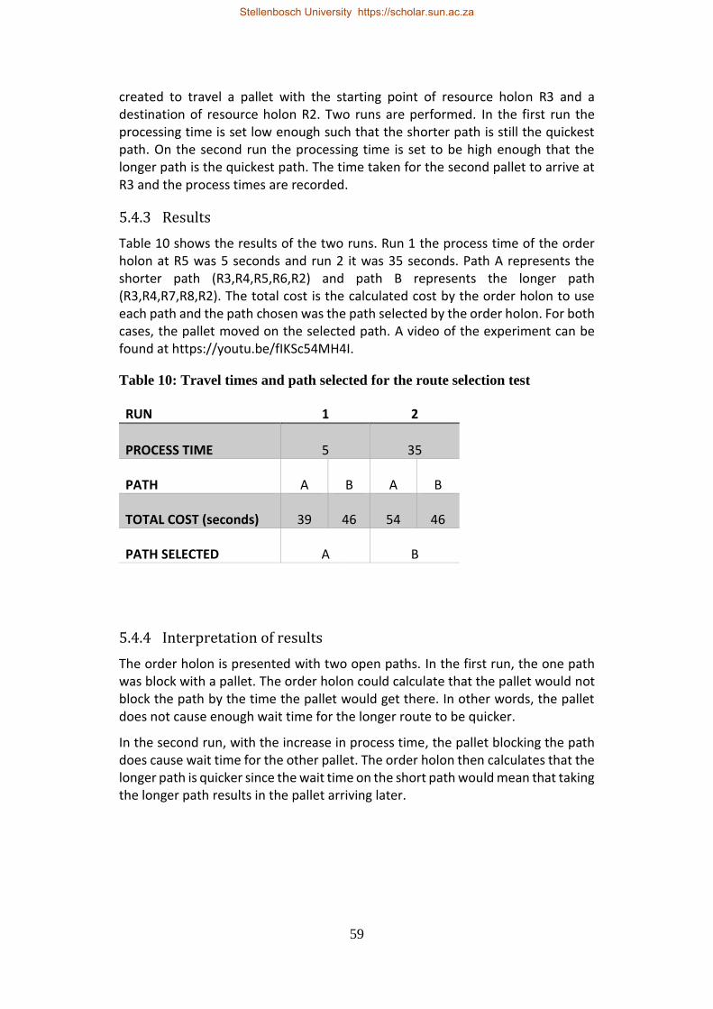
59
created to travel a pallet with the starting point of resource holon R3 and a destination of resource holon R2. Two runs are performed. In the first run the processing time is set low enough such that the shorter path is still the quickest path. On the second run the processing time is set to be high enough that the longer path is the quickest path. The time taken for the second pallet to arrive at R3 and the process times are recorded.
5.4.3 Results
Table 10 shows the results of the two runs. Run 1 the process time of the order holon at R5 was 5 seconds and run 2 it was 35 seconds. Path A represents the shorter path (R3,R4,R5,R6,R2) and path B represents the longer path (R3,R4,R7,R8,R2). The total cost is the calculated cost by the order holon to use each path and the path chosen was the path selected by the order holon. For both cases, the pallet moved on the selected path. A video of the experiment can be found at https://youtu.be/fIKSc54MH4I.
Table 10: Travel times and path selected for the route selection test
RUN 1 2
PROCESS TIME 5 35
PATH A B A B
TOTAL COST (seconds) 39 46 54 46
PATH SELECTED A B
5.4.4 Interpretation of results
The order holon is presented with two open paths. In the first run, the one path was block with a pallet. The order holon could calculate that the pallet would not block the path by the time the pallet would get there. In other words, the pallet does not cause enough wait time for the longer route to be quicker.
In the second run, with the increase in process time, the pallet blocking the path does cause wait time for the other pallet. The order holon then calculates that the longer path is quicker since the wait time on the short path would mean that taking the longer path results in the pallet arriving later.
Stellenbosch University https://scholar.sun.ac.za

60
5.5 Experiment: Dampening mechanisms and integrability
5.5.1 Objective
A resource holon is added to the conveyer system and creates a new path that is a more appealing path to two or more order holons. All order holons must see the existence of the better path and assess whether to take it or not. Based on the dampening mechanism for reselection of paths, all order holons should not select this path at the same time. To test the system’s integrability, the time taken to integrate the new resource holon is also measured.
5.5.2 Experimental procedure
Two order holons are created to move a pallet with the starting point of resource holon R3 and the destination of resource holon R2. Resource holon R5 is already turned off, making the path with resource holon R5 impossible to travel on. After both order holons have selected a path, resource holon R5 is switched on, which introduces a shorter path to the system. The selected routes are recorded.
5.5.3 Results
Figure 30 and Figure 31 shows an edited screenshot from the console. The screenshot was edited to remove all unnecessary information. The figures show the feasible paths discovered by the two order holons and the time it takes to travel those paths. In the second figure, it also shows the notification indicating that the controller successfully connected to the new resource holon. The first screenshot shows only one feasible path for each order holon while the second screenshot shows that they each have two feasible paths. On the first run, order holon 1 did not change path but on the second run it did. Order holon 2 never switches paths. A video of the experiment can be found at https://youtu.be/EppkoFIKhZE.
Figure 30: Edited screenshot of the console before turning on R5
Figure 31: Edited screenshot of the console after turning on R5
Order holon 1
Order holon 2
Order holon 1
Order holon 2
Stellenbosch University https://scholar.sun.ac.za

61
5.5.4 Interpretation of results
For the dampening mechanisms and integrability test, two runs were performed to illustrate the dampening mechanisms during route selection. In Figure 30, both order holons can only detect that there is only one feasible path. This indicates that only one feasible path exists. Figure 31 shows that the new resource holon has been integrated. The “LU connected” is notifying the console of a successful connection between the HHL and the LLC and it is the final step of inserting a new resource holon.
In addition, both order holons now detect that there is two feasible paths, proving that the resource holon has become part of the conveyor system. It can also be seen that the dampening mechanisms do work. Order holon 2 never changed paths since it did not meet the threshold criteria. Order holon 1 only changed routes once out of the two runs proving that the route reselection was dampened.
5.6 Experiment: Junction node test
5.6.1 Objective
Two orders holons are created that must use the same junction node to move across to a destination. Each pallet must use a different input and output combination. This is to test the route selection of the order holon and traffic management of the junction node resource holon.
5.6.2 Experimental procedure
Two order holons are created; one is to move a pallet from R8 to R1 and the other to move another pallet from R6 to R2. The test is preformed once more to move a pallet from R6 to R2 and another pallet from R8 to R2. The order holons are created right after to each other. The time taken for pallets to reach their destination is measured.
5.6.3 Results
Table 11 shows the start and end time for both runs. It gives an indication of which pallet moved first and when it successfully arrived at their destination. The path that each pallet travelled is also shown. A video of the experiment can be found at https://youtu.be/YGekrQUITFc.
Stellenbosch University https://scholar.sun.ac.za

62
Table 11: start and end times for the junction node test
RUN 1 2
PATH [R6, R2] [R8, R1] [R6, R2] [R8, R2]
START 0 3 5 0
END 11 15 31 19
5.6.4 Interpretation of results
When two order holons make bookings at a junction, the junction will give the slot on a first come first serve basis. In addition, the junction node will not allow another pallet into a junction while it is busy. This is proved by the start times of the pallets. Pallet B leaves after pallet A has exited the junction in the first run. In the second run, pallet A leaves after pallet B. This proves that the junction resource holon can effectively control pallet traffic.
5.7 Experiment: Customizability and scalability
5.7.1 Objective
A new resource holon is added in without any precoding. This is done to test the system’s customizability and scalability. The time taken to insert the new resource holon is measured and the system is tested to see if it is working.
5.7.2 Experimental procedure
From the experimental setup shown in Figure 26, resource holon R9 had not yet been integrated. For this test case, resource holon R9 was integrated into the conveyor system by inputting the required code into the transportation manager and updating the conveyor map. The conveyor map is described in Section 4.1. The time taken to implement resource holon R9 is measured. A pallet is tested to run on the system to check that the integration was successful.
5.7.3 Results
It took 4 min and 42 seconds to implement the new resource holon. A video showing that the resource is integrated can be found at https://youtu.be/EHvfQumtW6Q.
5.7.4 Interpretation of results
When a new resource holon is integrated, the only thing that needs to be done is to add the path in the conveyor map and trigger the transportation manager to
Stellenbosch University https://scholar.sun.ac.za
63
add new “receive” clauses that will handle the new pathway. With similar results shown in Section 5.3 the system reacts to the new resource holon once it is integrated. The 4 min and 42 seconds was the time taken to edit the text file and add the needed lines to the transportation manager. This proves the controller’s scalability and convertibility.
5.8 Evaluation of Erlang
As described in Section 2.6, Erlang is a functional programming language meaning that within a module, expressions are evaluated to determine which procedure to follow instead of commands. A module is a sequence of function declarations and attributes (Rouse, 2007). This means that when a function is called it will contain an expression and the process will try to match the function name and its attributes. Once the process finds a match it will execute the matched function. This is similar to the functionality of a “case” statement from other programming languages and which can have the same name of a function multiple times within a module provided that each function’s attributes are different. Programming in a functional programming language can be difficult to grasp if the programmer has no prior experience. However, Erlang is useful since you can call another instance of the function within itself without interrupting the function or causing infinite loops.
In addition, looping is handled in a similar manner, by tail recursion: a function recalls itself and the inputs are changed every time. When it is time for the loop to end, the attributes are changed to match the attributes of a version of the function that does not call the function within itself.
The nature of Erlang to evaluate expressions, as described above, was a convenient feature when programming the higher-lever communication and transport manager. Those two modules required a large number of messages to be filtered to a matching clause. Once a message was matched, a new process could be launched to deal with the remaining messages. There does not seem to be any advantages to this feature when programming the other modules.
Variables can hold any type of value and once a variable is assigned a value it cannot be changed. It can be convenient to not have to declare the variable types, and casting variables is done automatically, such as an integer changing to a float. However, when expressions are evaluated, it requires the type and value to be the same in order to match and the programmer will be required to take this into consideration when developing the program. When passing data around the conveyor controller it was useful to pass around variables without having to worry about the type of variable. It may cause the programmer extra time needed to debug.
Erlang has a useful feature known as records. This is like variables except it allows you to group the variables together which is referenced by one term. Once a function has passed the term it can access and change any of the variables. Records reduce the amount of programming lines when functions share a lot of
Stellenbosch University https://scholar.sun.ac.za

64
the same attributes since only the required variable from the record is typed out. When programming the order holon and the ant holons it is required to share a lot of data across functions. This feature proved useful since the programmer does not need to worry about having to correct the function attributes since the attributes are reduced to one.
Likely the greatest advantage of Erlang to this research is that it has light weight processes compared to other programming languages such as C# (C# vs Erlang, [S.a.]). Creating and terminating processes is done with a built-in function and can be easy to track. In fact, processes can be linked to one another. If a linked process fails it will send a signal to the parent process. The conveyor controller was designed from an architecture where there are multiple automatous entities, holons. Erlang is able to simulate this very well since each holon can be split into one or more processes. Linking processes gives a sense of a holarchy. If a process goes down none of the other processes are affected.
Erlang Term Storage (ETS) is another feature of Erlang. When an ETS table is created it allocates memory to storing terms and returns a unique key which can be used to access, add or remove terms. ETS table can be customize with settings that can restrict things such access or the type of terms and declare the order the terms are placed in the table. ETS also provides several built-in functions which allow the programmer to manipulate the ETS table such as searching for a specific term or list of terms based on an expression. The ETS table fits the concept of a blackboard well in the architecture. It acts as a standalone memory bank that can be accessed by any process that has the key and the built-in functions offers convenience to the programmer.
The final feature discussed here is Erlang’s built-in functionality for state machines. Erlang has two methods of executing a state machine. The first method is where states are only changed through events. An event can be a message from another process or a timeout from within the state machine. The second method is that states transition from one another. All states react to events in the same manner as before but events cannot be changed from other processes. The second method is useful when the programmer wants to add commands when the state machine enters or exits a state. The order holon was implemented with this method. The only advantage to using Erlang was that with all the built-in functionality, there was no difficulty with setting up and managing the state machine.
Most features mentioned in this section can be replicated in other programming languages. However, for the implementation of the architecture used in this thesis it was found that the built-in functionality was convenient. The ease of creating new processes made Erlang appropriate to use to implement the holonic architecture described in Chapter 3.
Stellenbosch University https://scholar.sun.ac.za

65
6 CONCLUSION AND RECOMMENDATIONS
The commonly used manufacturing systems, DML and FMS, have been insufficient in meeting the rapidly changing demands of the dynamic global market. The concept of an RMS was developed to possess responsiveness to manufacturing uncertainty caused by hardware or software failure, changes in the global market and changes in government regulations. RMSs are designed to respond in a rapid and cost-effective manner (Setchi and Lagos, 2004). However, RMSs are yet to be proven in practice.
The control of a palletised conveyor in a context where the routing of parts being manufactured has to be changed dynamically, taking into account other products and the limited resources of the transport system, presents a microcosm of an RMS.
The objective of this thesis is to evaluate Erlang's suitability for the controller of a reconfigurable palletised conveyor system, using an architecture based on PROSA and stigmergy. The strategy taken was to design and develop a controller for reconfigurable conveyor controller and subject the controller to testing on the conveyor system in the MADRG’s laboratory. The conveyor controller design was adapted from an architecture developed by Hadeli et al. (2004). The suitability is a qualitative measure and contributes to the work done by Kruger (2018).
The testing proved that the conveyor controller supported the characteristics of a reconfigurable system. In particular, the tests showed that the conveyor controller was able to:
• Handle the dynamic routing of multiple pallets without collisions;
• Avoid bottlenecks on the conveyor;
• Adapt the path of a pallet when a segment of the conveyor it planned to use, becomes unavailable; and
• Adapt the path of a pallet when a segment of the conveyor it had not planned to use, becomes available.
The controller developed in this thesis confirmed that Erlang has many built-in functions that aide in implementing the logic of a PROSA architecture using stigmergy. Programming each holon in its own module made it quick to create holons when required. The architecture requires a large number of threads since each ant, order and feasibility holon has its own process running concurrently. In addition, each resource holon is split into 3 processes. Erlang, being a concurrent programming language, is appropriate for this application since it creates, runs and terminates processes quickly and effectively. Multi-threading in Erlang is a lightweight process and can handle a larger number of threads than C# (C# vs Erlang, s.a.).
Future work that can be considered is to improve the forecasting of the conveyor controller. This could be done by adding the functionality to the controller where
Stellenbosch University https://scholar.sun.ac.za

66
times are regularity updated and based on the values the transport times are refreshed. The travel times would become more accurate as the system runs.
An additional opportunity for future work is to put the conveyor controller into a simulation and test the controller with a more complex conveyor. The simulation could run more pallets and test the conveyor controller under more extreme conditions. Havenga (2017) has already created a complex conveyor system using Simio, which could be adapted to simulate the conveyor controller developed for this thesis.
Stellenbosch University https://scholar.sun.ac.za

67
REFERENCES
C# vs Erlang. [S.a.]. [Online]. Available: https://www.slant.co/versus/115-/11675/~c_vs_erlang
Dlits, D.M., Boyd, N.P. and Whorms, H.H., 1991. The Evolution of Control Architectures for Automated Manufacturing Systems. Journal of Manufacturing Systems. Vol. 10, No. 1:79-93
Giret, A. and Vicente, B., 2004. Holons and Agents. Journal of Intelligent Manufacturing. Vol. 15:645-659
Hadeli, Valckenaers, P., Kollingbaum, M. and Van Brussel, H., 2004. Multi-agent coordination and control using stigmergy. Computers in Industry. Vol. 53: 75-96
Havenga, P., 2017. Pallet Routing Strategies for a Reconfigurable Conveyor. MEng Thesis. Stellenbosch University.
Keshavarzmanesh, S., Wang, L. and Feng, H.Y., 2010. A hybrid approach for dynamic routing planning in an automated assembly shop. Robotics and Computer-Integrated Manufacturing. Vol. 26, No. 6: 768-777.
Koestler, A., 1969. The Ghost in the Machine. Arkana Books, London.
Koren, Y., 2006. Reconfigurable Manufacturing Systems and Transformable Factories. Springer.
Koren, Y., Heisel, U., Jovane, F., Moriwaki, T., Pritschow, G., Ulsoy, G. and Van Brussel, H., 1999. Reconfigurable Manufacturing Systems. CIRP Annals - Manufacturing Technology. Vol. 48, No. 2: 527-540.
Koren, Y. and Shpitalni, M., 2010. Design of reconfigurable manufacturing systems. Journal of Manufacturing Systems. Vol. 29, No. 4: 130-141.
Stellenbosch University https://scholar.sun.ac.za

68
Kotzé, M.J., 2016. Modular Control of a Reconfigurable Conveyer System. MEng Thesis. Stellenbosch University.
Kruger, K., 2018. Development and Evaluation of an Erlang Control System for Reconfigurable Manufacturing Systems. PhD Dissertation. Stellenbosch University.
Kruger, K. and Basson, A.H., 2015. Implementation of an Erlang-based Resource Holon for a Holonic Manufacturing Cell. Studies in Computational Intelligence. Vol. 594: 49-58.
Kruger, K. and Basson, A.H., 2016. Erlang-based control implementation for a holonic manufacturing cell. International Journal of Computer Integrated Manufacturing. DOI: 10.1080/0951192X.2016.1195923
Le Roux, A., 2013. Control of a Conveyor System for a Reconfigurable Manufacturing Cell. MEng Thesis. Stellenbosch University.
Leitão, P., 2009. Agent-based distributed manufacturing control: A state-of-the-art survey. Engineering Applications of Artificial Intelligence. Vol. 22, No. 7: 979-991.
Rouse, M., 2007. Definition: Erlang programming language. [Online]. Available:
http://whatis.techtarget.com/definition/Erlang-programming-language
Setchi, R.M. and Lagos, N., 2004. Reconfigurability and Reconfigurable Manufacturing Systems - State-of-the-art Review. 2nd IEEE International Conference on Industrial Informatics. pp.: 529-535.
Stock, P. and Zülch, G., 2012. Reactive manufacturing control using the ant colony approach. International Journal of Production Research. Vol. 50, No. 21:6150-6161
Valckenaers, P. and Van Brussel, H., 2016. Design for the unexpected: From Holonic Manufacturing Towards a Humane Mechatronics Society. Butterworth-Heinemann, Oxford.
Stellenbosch University https://scholar.sun.ac.za

69
Van Brussel, H., Wyns, J., Valckenaers, P., Bongaerts, L. and Peeters, P., 1998. Reference architecture for holonic manufacturing systems: PROSA. Computers in Industry. Vol. 37, No. 3: 255-274.
Van Leeuwen, E.H., and Norrie, D., 1997. Holons and Holarchies. Manufacturing Engineer. 86-88 April
Stellenbosch University https://scholar.sun.ac.za

70
APPENDIX A: COMMANDS TO LLC
In this appendix, a description of the PLCs within the conveyor system in the MADRG’s laboratory is given. There are six PLCs which each control a conveyor module, shown in Figure 32. The PLCs communicate using TCP/IP. Once another controller is connected to a PLC it will send 1 byte every 200ms to the controller which will indicate the status of the PLC which is a combination of the previous command and give a value of the sensor(s) being triggered by a pallet(s).
Figure 32: Placement of conveyor modules (Kotzé, 2016)
PLC 1, 2 and 5: Lifting unit 1, 2 and 3
There are 3 lifting unit modules in the conveyor system. The lifting unit module, shown in Figure 33, has the capability to lift a pallet. It is also able to stop pallets in front of the lifting component using a stop gate and detect whether a pallet is present there or not using the proximity switch.
Stellenbosch University https://scholar.sun.ac.za

71
Figure 33: Lifting unit module (Kotzé, 2016)
The commands of the lifting unit are listed in Table 12. When a lifting unit’s proximity sensor is triggered it will add 0001 0000 to the received byte.
Table 12: Available commands for the lifting unit Command Description byte sent
Stop The conveyor is started 0000 0000
Stop and check The conveyor motor is started 0000 0001
Lift The pallet is released from the stop gate and the lifted 0000 0010
Pass A pallet is released from the stop gate and allowed to pass
0000 0011
Release A lifted pallet is lowered and allowed to move pass 0000 0100
PLC 3: Lifting unit with a transverse conveyor
The lifting unit with a transvers conveyor module, shown in Figure 34, works like the lifting unit described in the previous section, except when the lift command is issued it will traverse the pallet to the lifting component. All the commands listed in Table 12 are the same. When the proximity sensor is triggered it will add 0001 0000 to the received byte. The PLC will add 0010 0000 to the received byte if the left rocker proximity switch is triggered and 0100 0000 if the right rocker proximity switch is triggered.
Stellenbosch University https://scholar.sun.ac.za

72
Figure 34: Lifting unit with transverse conveyor (Kotzé, 2016)
PLC 4: Divert module
The task of the divert module, shown in Figure 35, is to transfer a pallet from one path on a conveyor to another. It also can stop pallets at the stop gates and detect the pallet’s presence using a proximity sensor.
Stellenbosch University https://scholar.sun.ac.za

73
Figure 35: Divert module
The commands available for the divert module is shown is Table 13. When the proximity sensor has a pallet in range it will add 0001 0000 to the received byte and when the rocker proximity switch is triggered it will add 0010 0000 to the received byte.
Table 13: Available commands for the divert module Command Description byte sent
Stop The conveyor is started 0000 0000
Stop and check The conveyor motor is started 0000 0001
Divert The pallet is moved from one path to the another 0000 0010
Pass A pallet is released from the stop gate and allowed to pass
0000 0011
PLC 6: Traverse conveyor with pallet magazine
The final PLC is controls a module that allows the pallet to switch between 2 paths on the conveyor, as well as move to and from the pallet magazine. It also can stop pallets at any of the entrances using stop gates and has several sensors that are able to detect the presence of a pallet. The module is shown in Figure 36.
Stellenbosch University https://scholar.sun.ac.za

74
Figure 36: Traverse conveyor with pallet magazine
The available commands for this module are listed in Table 14. The main track is transverse conveyor A and the secondary track is transverse conveyor B.
Table 14: Available commands for the transverse module with pallet magazine Command Description byte sent
Stop The conveyor is started 0000 0000
Stop and check The conveyor motor is started 0000 0001
Divert_main_to_secondary The pallet is moved from the main track to the secondary track
0000 0010
Pass A pallet is released from the stop gate and allowed to pass on the main track
0000 0011
Divert_secondary_to_magazine
The pallet is moved from the secondary track to the pallet magazine
0000 0100
Divert_main_to_magazine The pallet is moved from the main track to the pallet magazine
0000 0110
Divert_magazine_to_main The pallet is moved from the pallet magazine to the main track
0000 0111
Stellenbosch University https://scholar.sun.ac.za

75
APPENDIX B: CONTROLLER CODE
This section provides the code snippets of the controller.
B.1 Order holon state machine
The first code snippet provided is the order holon. It shows the code of a state machine used for the order holon.
%%%%%%%%%%%%%%%%%%%%%%%%%%%%%%%%%%%%%%%%
%%%%%%%%%%%%%%%%%%%%%%%%%%%%%%%%%%%%%%%%
-module('Order_Holon').
-behaviour(gen_statem).
-export([init/1,callback_mode/0,terminate/3,code_change/4]).
-export([start/4,stop/1]).
-
export([route_selection/3,waiting_for_ant/3,waiting_for_pallet/3,r
oute_selection_waiting_for_exploration_ant/3,waiting_to_proceed/3]
).
%Starts state machine
start(_desired_destination,_orderID,_current_resourceID,_est_proce
ss_time) ->
gen_statem:start(?MODULE,
[_desired_destination,_orderID,_current_resourceID,_est_process_ti
me], []).
%Init all parameters
init([_desired_destination,_orderID,_current_resourceID,_est_proce
ss_time]) ->
_blackboardID = 0,
register(_orderID,self()), %Registers order holon on system
Data = #{old_cost_of_path => 0,stored_path =>
[],old_selected_path => [],cost_of_path =>
infinity,number_of_paths => 0,
desired_destination => _desired_destination,
orderID => _orderID,current_resourceID => _current_resourceID,
blackboardID=>_blackboardID,est_process_time=>_est_process_time,bo
okings_list=>[]},
{ok,route_selection,Data}. %Change to route selection state
callback_mode() ->
[state_functions,state_enter].
%Enter route selection.
route_selection(enter,_OldState,#{current_resourceID :=
_current_resourceID} = Data) ->
Stellenbosch University https://scholar.sun.ac.za

76
_current_resourceID ! {request_blackboardID_cast,self()},
{keep_state_and_data,[]};
route_selection(cast,{blackboardID_recieved,_blackboardID},#{desir
ed_destination := _desired_destination,orderID :=
_orderID,current_resourceID :=
_current_resourceID,est_process_time:=_est_process_time} = Data)
->
%At this point all feasible paths are read off
_feasible_paths = ets:match_object(_blackboardID,
{1,_desired_destination,'_','_','_','_'}),
_number_of_paths =
path_explore(_feasible_paths,_current_resourceID,_desired_destinat
ion,_orderID,_blackboardID,0,_est_process_time),
%An ant holon is created to explore every path.
{next_state,route_selection_waiting_for_exploration_ant,Data
#{blackboardID:=_blackboardID,number_of_paths :=
_number_of_paths}}.
%Enters a state of waiting for the return of exploration ants
route_selection_waiting_for_exploration_ant(enter,_OldState,#{curr
ent_resourceID := _current_resourceID} = Data) ->
{keep_state_and_data,{state_timeout,3000,error}};
%When an exploration ant returns the order holon logs the cost
route_selection_waiting_for_exploration_ant(cast,{exploration_succ
essful,_path,_total_cost},
#{bookings_list := _bookings_list,blackboardID :=
_blackboardID,
number_of_paths := _number_of_paths, desired_destination :=
_desired_destination,
orderID := _orderID,current_resourceID := _current_resourceID,
est_process_time:=_est_process_time,
cost_of_path := _prev_cost,old_selected_path :=
_old_selected_path,
stored_path:=_stored_path,old_cost_of_path := _old_cost} = Data) -
>
if
_total_cost < _prev_cost -> %Costs are
compared
_new_cost = _total_cost,
_new_path = _path;
true ->
_new_cost = _prev_cost,
_new_path = _stored_path
end,
if
_number_of_paths == 1 -> %After determining the
best path again.
Stellenbosch University https://scholar.sun.ac.za

77
_reselect_check = reselect_check(),
if
_old_selected_path == [] ->
%Spawns intention ant on chosen path
spawn('Ant_Holon_I_O',start,[_desired_destination,_new_path,
_current_resourceID,_orderID,_blackboardID,_est_process_time]),
{next_state,waiting_for_ant,Data#{old_selected_path:=_new_pa
th,number_of_paths := (_number_of_paths-1),old_cost_of_path :=
_new_cost}} ;
_old_cost > (_new_cost*1.30) andalso
_reselect_check == true -> %Change to new path
spawn('Ant_Holon_D_O',start,[_bookings_list,
_current_resourceID,_orderID]),
spawn('Ant_Holon_I_O',start,[_desired_destination,_new_path,
_current_resourceID,_orderID,_blackboardID,_est_process_time]),
{next_state,waiting_for_ant,Data#{old_selected_path:=_new_pa
th,number_of_paths := (_number_of_paths-1),old_cost_of_path :=
_new_cost}} ;
true -> %keep old path
spawn('Ant_Holon_I_O',start,[_desired_destination,_new_path,
_current_resourceID,_orderID,_blackboardID,_est_process_time]),
{next_state,waiting_for_ant,Data#{number_of_paths :=
(_number_of_paths-1),cost_of_path := _new_cost}}
end;
true ->
{keep_state,Data#{stored_path:=_new_path,number_of_paths :=
(_number_of_paths-1),cost_of_path := _new_cost}}
end;
route_selection_waiting_for_exploration_ant(state_timeout,error,Da
ta) ->
{next_state,route_selection,Data,[]}.
reselect_check() -> %Dampening mechanism
_int = random:uniform(100),
if
_int =< 25 ->
_new_check = true;
true ->
_new_check = false
end,
_new_check.
path_explore([],_current_resourceID,_remaining_bookings,_orderID,_
blackboardID,_number_of_paths,_est_process_time) ->
_number_of_paths;
Stellenbosch University https://scholar.sun.ac.za

78
path_explore(_feasible_paths,_current_resourceID,_desired_destinat
ion,_orderID,_blackboardID,_number_of_paths,_est_process_time) ->
[_first_entry|_remaining_paths] = _feasible_paths,
{1,_,_route_info,_,_,_} = _first_entry,
spawn('Ant_Holon_E_O',start,[_desired_destination,_route_inf
o,_current_resourceID,_orderID,_blackboardID,_est_process_time]),
path_explore(_remaining_paths,_current_resourceID,_desired_d
estination,_orderID,_blackboardID,_number_of_paths+1,_est_process_
time).
%Wait for intention ant to confirm the booking
waiting_for_ant(enter,_OldState,Data) ->
{keep_state_and_data,[{state_timeout,30000,error}]};
waiting_for_ant(cast,{bookings_successful,[_final_bookings_list,_f
inal_accumumlative_cost]},#{blackboardID := _blackboardID,orderID
:= _orderID,current_resourceID := _current_resourceID} = Data)
->
%Since all bookings have been made need to set current
status to waiting_to_process. So that it can be realeased.
_current_resourceID !
{set_status,_orderID,waiting_to_proceed}, %Set status that pallet
is ready to move
{next_state,waiting_to_proceed,Data#{bookings_list
:=_final_bookings_list,old_cost_of_path :=
_final_accumumlative_cost}};
waiting_for_ant(state_timeout,error,Data) ->
io:format("timeout enter waiting for ant~n"),
{next_state,route_selection,[],[]}.
%Wait for pallet to move
waiting_to_proceed(enter,_OldState,Data) ->
{keep_state_and_data,[{state_timeout,30000,error}]};
waiting_to_proceed(cast,{pallet_released,[]},#{blackboardID :=
_blackboardID,orderID := _orderID,
current_resourceID := _current_resourceID,bookings_list
:=_final_bookings_list} = Data) ->
[_current_booking|_remiaing_bookings] =
_final_bookings_list,
{2,_prev_resourceID2,_,_,_,_,_,_} = _current_booking,
case _prev_resourceID2 of
[] ->
_final_bookings_list1 = _remiaing_bookings;
_ ->
_final_bookings_list1 = _final_bookings_list
end,
[_next_booking1,_following_booking1|_remaining_bookings1] =
_final_bookings_list1,
Stellenbosch University https://scholar.sun.ac.za

79
{2,_next_resourceID,_,_,_,_,_,_} = _following_booking1,
%Checks if junction node or resource node.
%Updates status to what is needed at node
_atom_in_string = atom_to_list(_next_resourceID),
[_j_or_r|_] = _atom_in_string,
case _j_or_r of
106 ->
_new_final_bookings_list =
[_following_booking1|_remaining_bookings1],
_next_resourceID !
{set_status,_orderID,travelling};
_ ->
_new_final_bookings_list =
_final_bookings_list1,
_next_resourceID ! {set_status,_orderID,queuing}
end,
{next_state,waiting_for_pallet,Data#{bookings_list
:=_new_final_bookings_list}};
waiting_to_proceed(state_timeout,error,Data) ->
io:format("time out waiting_to_proceed~n"),
stop(shutdown),
{next_state,route_selection,[],[]}.
waiting_for_pallet(enter,_OldState,#{bookings_list :=
_bookings_list,orderID := _orderID} = Data) ->
{keep_state_and_data,[{state_timeout,60000,error}]};
waiting_for_pallet(cast,{movement_success,[]},#{bookings_list :=
_bookings,desired_destination := _desired_destination,orderID :=
_orderID} = Data) ->
[_next_booking,_following_bookings|_remaining_bookings] =
_bookings,
{2,_current_resourceID,_next_resourceID,_,_,_,_,_} =
_next_booking, %Technically the current resourceID when travelling
accross a jn would be the prev_resourceID.
%Checks if junction node or resource node.
%Updates status to what is needed at node
_atom_in_string = atom_to_list(_current_resourceID),
[_j_or_r|_] = _atom_in_string,
case _j_or_r of
106 ->
_current_resourceID !
{set_status,_orderID,checked_out};
_ ->
[]
end,
case _next_resourceID of
_desired_destination ->
_next_resourceID !
{set_status_final,_orderID,waiting_to_be_processed},
stop(shutdown);
_ ->
Stellenbosch University https://scholar.sun.ac.za

80
[]
end,
%Change resourceID to next one in path
{next_state,route_selection,Data#{current_resourceID :=
_next_resourceID,bookings_list
:=[_following_bookings|_remaining_bookings]}};
waiting_for_pallet(state_timeout,error,Data) ->
io:format("timeout enter waiting for pallet~n"),
stop(shutdown),
{next_state,waiting_for_pallet,[],[]}.
terminate(_Reason, State, _Data) ->
ok.
stop(Reason) ->
gen_statem:stop(self(),Reason,infinity).
code_change(_Vsn, State, Data, _Extra) ->
{ok, State,
Data}.%%%%%%%%%%%%%%%%%%%%%%%%%%%%%%%%%%%%
%%%%
%%%%%%%%%%%%%%%%%%%%%%%%%%%%%%%%%%%%%%%%
B.2 Intention ant
The code from the intention ant holon is provided. The exploration ant holon’s code is omitted since it is similar to the intention ant holon. The exploration ant holon does not make bookings when requesting a booking.
%%%%%%%%%%%%%%%%%%%%%%%%%%%%%%%%%%%%%%%%
%%%%%%%%%%%%%%%%%%%%%%%%%%%%%%%%%%%%%%%%
-module('Ant_Holon_I_O').
-export([start/6,moving/1,communicating/1]).
%Order holon sends out an ant and generates booking along with a
total accumulated cost. The order holon will determine which is
the best route based
%the weighted value.
%The ant will need to move to the next resource holon. Request
earliest start time (which is latest end time) and end time for a
destination (so no black board is needed).
%Then must add up cost for path and move to next holon.
Stellenbosch University https://scholar.sun.ac.za

81
start(_destinationID,_path_to_inspect,
_current_resourceID,_orderID,_current_blackboardID,_est_process_ti
me) ->
%Create record that will be passed
Data = #{path_to_inspect_unchanged => _path_to_inspect,
current_resourceID =>_current_resourceID, bookings_list => [],
path_to_inspect =>
[place_holder|_path_to_inspect], destinationID =>
_destinationID,orderID => _orderID,prev_resourceID => [],
est_process_time =>
_est_process_time,accumulated_cost => 0,desired_start_time =>
time(),
stored_booking =>
{2,[],_current_resourceID,_orderID,time(),time(),time(),queuing_at
_front}},
moving(Data).
moving(Data) ->
#{path_to_inspect := _path_to_inspect, current_resourceID :=
_current_resourceID, destinationID := _destinationID,orderID :=
_orderID} = Data,
%move to downstream holon
%example format of _path_to_inspect:
[r1,jn1,r2,r3,r4,jn2,r5,r6]
[_prev_resourceID,_current_resourceID,_next_resourceID|_rema
ining_path] = _path_to_inspect,
communicating(Data#{current_resourceID :=
_next_resourceID,path_to_inspect :=
[_current_resourceID,_next_resourceID|_remaining_path],prev_resour
ceID := _current_resourceID}).
communicating(Data) ->
#{current_resourceID := _current_resourceID,orderID :=
_orderID,destinationID := _destinationID,
bookings_list := _bookings_list,
path_to_inspect := _path_to_inspect,prev_resourceID :=
_prev_resourceID,
est_process_time
:=_est_process_time,accumulated_cost :=
_accumulated_cost,desired_start_time := _desired_start_time,
stored_booking := _stored_booking,
path_to_inspect_unchanged := _path_to_inspect_unchanged} = Data,
[_prev_resourceID,_current_resourceID|_] =
_path_to_inspect,
%How a booking is requested.
%Determines whether a junction node or resource. Acts
accordinglu
_atom_in_string = atom_to_list(_current_resourceID),
[_j_or_r|_] = _atom_in_string,
case _j_or_r of
106 ->
%This will create a booking along the path
[_prev_resourceID,_current_resourceID,_next_resourceID|_] =
_path_to_inspect,
Stellenbosch University https://scholar.sun.ac.za

82
_current_resourceID !
{request_opening_I,_prev_resourceID,_next_resourceID,_orderID,_des
ired_start_time,self()};
_ ->
[_prev_resourceID,_current_resourceID|_] = _path_to_inspect,
_current_resourceID !
{request_opening,_prev_resourceID,_current_resourceID,_orderID,_de
sired_start_time,self()}
end,
receive
{requested_opening,_start_time,_end_time} ->
case _current_resourceID of
_destinationID ->
_final_end_time =
calendar:seconds_to_time(calendar:time_to_seconds(_end_time)+_est_
process_time),
_final_accumumlative_cost =
_accumulated_cost + calendar:time_to_seconds(_end_time) -
calendar:time_to_seconds(_start_time),
case _stored_booking of
[] ->
_final_bookings_list =
_bookings_list;
_ ->
_atom_in_string2 =
atom_to_list(_prev_resourceID),
[_j_or_r2|_] =
_atom_in_string2,
case _j_or_r2 of
106 ->
_final_bookings_list = _bookings_list;
_ ->
_booking_to_make1
= setelement(6,_stored_booking,_start_time),
_final_bookings_list =
lists:append(_bookings_list,[_booking_to_make1]),
_prev_resourceID !
{make_booking,_orderID,_booking_to_make1,self()}
end
end,
_booking_to_make2 =
{2,_prev_resourceID,_destinationID,_orderID,_start_time,_end_time,
time(),planning_queuing},
Stellenbosch University https://scholar.sun.ac.za

83
_current_resourceID !
{make_booking,_orderID,_booking_to_make2,self()},
_booking_to_make3 =
{2,_destinationID,[],_orderID,_end_time,_final_end_time,time(),pla
nning_processing},
_current_resourceID !
{make_booking_final,_orderID,_booking_to_make3,self()},
_final_bookings_list2 =
lists:append(_final_bookings_list,[{2,_prev_resourceID,_destinatio
nID,_orderID,_start_time,_end_time,time(),planning_queuing},{2,_de
stinationID,[],_orderID,_end_time,_final_end_time,time(),planning_
processing}]),
gen_statem:cast(_orderID,{bookings_successful,[_final_bookin
gs_list2,_final_accumumlative_cost]}),
exit(complete);
_ ->
%If prev_resourceID is a jn then I need to
make the booking for
_new_accumumlative_cost =
_accumulated_cost + calendar:time_to_seconds(_end_time) -
calendar:time_to_seconds(_start_time),
_atom_in_string2 =
atom_to_list(_prev_resourceID),
[_j_or_r3|_] = _atom_in_string2,
case _j_or_r3 of
106 ->
[_prev_resourceID,_current_resourceID,_next_resourceID3|_] =
_path_to_inspect,
_booking_to_make =
{2,_prev_resourceID,_current_resourceID,_orderID,_start_time,_end_
time,time(),planning_queuing},
_stored_booking_update =
_booking_to_make,
_new_bookings_list =
_bookings_list; %If the prev_resouceID is a jn then no booking
needs to be made. Start time already the same as end time
_ ->
_atom_in_string3 =
atom_to_list(_current_resourceID),
[_j_or_r4|_] =
_atom_in_string3,
case _j_or_r4 of
106 ->
case
_stored_booking of
[] ->
%If stored booking is empty means no booking needs to be made
because it is the first resource after
_new_bookings_list1 = _bookings_list;
Stellenbosch University https://scholar.sun.ac.za

84
_ ->
_booking_to_make =
setelement(6,_stored_booking,_start_time),
_new_bookings_list1 =
lists:append(_bookings_list,[_booking_to_make]),
_prev_resourceID !
{make_booking,_orderID,_booking_to_make,self()}
end,
[_prev_resourceID,_current_resourceID,_next_resourceID3|_] =
_path_to_inspect,
_booking_to_make2
=
{2,_prev_resourceID,_next_resourceID3,_orderID,_start_time,_end_ti
me,time(),planning_travel},
_stored_booking_update = _booking_to_make2,
_new_bookings_list
= lists:append(_new_bookings_list1,[_booking_to_make2]); %If the
prev_resouceID is a jn then no booking needs to be made. Start
time already the same as end time;
_ ->
case
_stored_booking of
[] ->
_stored_booking_update =
{2,_prev_resourceID,_current_resourceID,_orderID,_start_time,_end_
time,time(),planning_queuing},
_new_bookings_list = []; %If stored booking is empty means
no booking needs to be made because it is the first resource after
_ ->
_stored_booking_update =
{2,_prev_resourceID,_current_resourceID,_orderID,_start_time,_end_
time,time(),planning_queuing},
_booking_to_make =
setelement(6,_stored_booking,_start_time),
_new_bookings_list =
lists:append(_bookings_list,[_booking_to_make]),
_prev_resourceID !
{make_booking,_orderID,_booking_to_make,self()}
end
end
end,
moving(Data#{bookings_list :=
_new_bookings_list,accumulated_cost :=
_new_accumumlative_cost,desired_start_time :=
_end_time,stored_booking := _stored_booking_update})
Stellenbosch University https://scholar.sun.ac.za

85
end
after
20000 ->
%resource holon unresponsive. terminate ant.
exit(resource_holon_inactive)
end.
%%%%%%%%%%%%%%%%%%%%%%%%%%%%%%%%%%%%%%%%
%%%%%%%%%%%%%%%%%%%%%%%%%%%%%%%%%%%%%%%%
B.3 Resource holon blackboard manager
The next code snippet provided is from the blackboard manager of the resource holon. It shows how the expiration check is performed for the 2nd layer. The code snippet is the same for regular resource holons and junction resource holons.
%%%%%%%%%%%%%%%%%%%%%%%%%%%%%%%%%%%%%%%%
%%%%%%%%%%%%%%%%%%%%%%%%%%%%%%%%%%%%%%%% %Check for the expiration of an entry for the 2nd layer.
%Receives a list of all the entries.
experation_check_schedule(_list_to_check,_blackboardID,_experation
_limit) ->
case _list_to_check of
[] ->
[];
_ ->
[H|T] = _list_to_check,
{2,_,_,_,_,_,_time_stamp,_} = H,
%convert time to seconds
{_h_stamp,_m_stamp,_s_stamp} = _time_stamp,
{_h_actual,_m_actual,_s_actual} = time(),
_time_difference = (_h_actual-_h_stamp)*60*60 +
(_m_actual-_m_stamp)*60 + (_s_actual-_s_stamp),
case T of
[] when _time_difference >
_experation_limit ->
%Entry has expired
ets:match_delete(_blackboardID,H);
_ when _time_difference >
_experation_limit ->
%Entry is fine
ets:match_delete(_blackboardID, H),
experation_check_schedule(T,_blackboardID,_experation_limit)
;
[] ->
[];
Stellenbosch University https://scholar.sun.ac.za

86
_ ->
experation_check_schedule(T,_blackboardID,_experation_limit)
end
end.
%%%%%%%%%%%%%%%%%%%%%%%%%%%%%%%%%%%%%%%%
%%%%%%%%%%%%%%%%%%%%%%%%%%%%%%%%%%%%%%%%
B.4 Junction resource holon
The final code snippet added is for the junction resource holon route selection. The regular resource holon is similar, but does not have the extra step of requesting to the downstream resource holon.
%%%%%%%%%%%%%%%%%%%%%%%%%%%%%%%%%%%%%%%%
%%%%%%%%%%%%%%%%%%%%%%%%%%%%%%%%%%%%%%%% %Determines when there is an opening
time_generator(_blackboardID,_orderID,_prev_resourceID,_next_resou
rceID,_desired_start_time,_list_of_upstream_resourceID_and_cost,_r
esourceID) ->
_list_of_bookings = ets:match_object(_blackboardID,
{2,'_','_','_','_','_','_','_'}), %obtains all bookings
%Sorts them from earliest to latest
_sorting_criteria = fun(J,I) ->
{2,_,_,_,_,_end_time_of_booking1,_,_} = J,
{2,_,_,_,_,_end_time_of_booking2,_,_} = I,
_end_time_of_booking1>_end_time_of_booking2 end,
_sorted_list_of_bookings = lists:sort(_sorting_criteria,
_list_of_bookings),
%Obtain travel time
_travel_time =
travel_time_finder_1st_layer(_prev_resourceID,_next_resourceID,_li
st_of_upstream_resourceID_and_cost,0),
{_start_time,_end_time_with_travel_time} =
availibility_check(_sorted_list_of_bookings,_orderID,_travel_time,
_desired_start_time),
_next_resourceID !
{request_opening,_resourceID,_next_resourceID,_orderID,_end_time_w
ith_travel_time,self()},
receive
{requested_opening,_start_time_from_next_resource,_end_time_
from_next_resource} ->
_new_desired_start_time =
calendar:seconds_to_time(calendar:time_to_seconds(_start_time_from
_next_resource)-_travel_time),
{_final_start_time,_final_end_time_with_travel_time} =
availibility_check(_sorted_list_of_bookings,_orderID,_travel_time,
_new_desired_start_time)
Stellenbosch University https://scholar.sun.ac.za

87
after
500 ->
{_final_start_time,_final_end_time_with_travel_time} =
{_start_time,_end_time_with_travel_time}
end,
{_final_start_time,_final_end_time_with_travel_time}.
travel_time_finder_1st_layer(_prev_resourceID,_next_resourceID,[],
_travel_time) ->
_travel_time;
travel_time_finder_1st_layer(_prev_resourceID,_next_resourceID,_li
st_of_upstream_resourceID_and_cost,_travel_time) ->
[_first_entry,_2nd_layer_list|_remaining_entries] =
_list_of_upstream_resourceID_and_cost,
case _first_entry of
_next_resourceID ->
%io:format("The travel time to ~w is~n",
[_first_entry]),
_new_travel_time =
travel_time_finder_2nd_layer(_2nd_layer_list,_prev_resourceID,0),
travel_time_finder_1st_layer(_prev_resourceID,_next_resource
ID,[],_new_travel_time);
_ ->
travel_time_finder_1st_layer(_prev_resourceID,_next_resource
ID,_remaining_entries,_travel_time)
end.
travel_time_finder_2nd_layer([],_prev_resourceID,_travel_time)
->
_travel_time;
travel_time_finder_2nd_layer(_2nd_layer_list,_prev_resourceID,_tra
vel_time) ->
[_first_entry,_new_travel_time|_remaining_entries] =
_2nd_layer_list,
case _first_entry of
_prev_resourceID ->
travel_time_finder_2nd_layer([],_prev_resourceID,_new_travel
_time);
_ ->
travel_time_finder_2nd_layer(_remaining_entries,_prev_resour
ceID,_travel_time)
end.
availibility_check([],_orderID,_travel_time,_start_time) ->
_end_time =
calendar:seconds_to_time(calendar:time_to_seconds(_start_time)+_tr
avel_time),
{_start_time,_end_time};
Stellenbosch University https://scholar.sun.ac.za

88
availibility_check(_sorted_list_of_bookings,_orderID,_travel_time,
_start_time) ->
%find soonest start time after start time
[_first_entry|_remaining_bookings] =
_sorted_list_of_bookings,
_end_time_to_check =
calendar:seconds_to_time(calendar:time_to_seconds(_start_time)+_tr
avel_time),
{2,_,_,_orderID_of_booking,_start_time_of_booking,_end_time_
of_booking,_,_} = _first_entry,
case _orderID_of_booking of
_orderID ->
availibility_check(_remaining_bookings,_orderID,_travel_time
,_start_time);
_ when (_start_time_of_booking =< _start_time) andalso
(_end_time_of_booking >= _end_time_to_check) ->
availibility_check(_remaining_bookings,_orderID,_travel_time
,_end_time_of_booking);
_ ->
availibility_check(_remaining_bookings,_orderID,_travel_time
,_start_time)
end.
%%%%%%%%%%%%%%%%%%%%%%%%%%%%%%%%%%%%%%%%
%%%%%%%%%%%%%%%%%%%%%%%%%%%%%%%%%%%%%%%%
Stellenbosch University https://scholar.sun.ac.za