evaluation of correction factors applied in photon
TRANSCRIPT

Journal of American Science, 2011;7(3) http://www.americanscience.org
http://www.americanscience.org [email protected] 758
meWQDg
1=
Evaluation of Correction Factors Applied in Photon Calibration of NIS TE Neutron Ionization Chambers
A. I. Abd El-Hafez*1 and M. Ezzat1
1Radiation Metrology Dept., National Institute for Standards (NIS), Giza, Egypt. *[email protected]
Abstract: Calibrations of two tissue equivalent (TE) ionization chamber were made in five photon beams (100 kV, 180 kV, 250 kV, l37Cs and 60Co) with two different pure gases namely acetylene C2 H2 and carbon dioxide CO2. The different calibration factors were compared both for in-air and in-water phantom, the measurements were performed according to the international atomic energy agency (IAEA) recommendations. For ionization chamber the total absorbed dose can be derived from the charge produced within its cavity employing a number of physical parameters. To discuss the charge produced in the cavity several correction factors which are related to the operational characteristics of the chambers have to be introduced. Information on the operational characteristics of two TE neutron ionization chambers were studied as a function of the effects of the warm-up to 3 hours, polarity, stem scattering, ion recombination, leakage current. Six different caps 1, 2, 3, 4, 6 and 8 mm were used to investigate wall thickness effect. Also, gas flow rate up to 31 ml/min and the radial & axial uniformity were investigated. [A. I. Abd El-Hafez and M. Ezzat Evaluation of Correction Factors Applied in Photon Calibration of NIS TE Neutron Ionization Chambers Journal of American Science 2011;7(3):758-772]. (ISSN: 1545-1003). http://www.americanscience.org. Key words: Tissue Equivalent Neutron Ionization Chambers- Photon Calibration- Correction Factors. 1. Introduction:
The increase in the number of centers throughout the world which are using fast neutrons for radiotherapy has led to a need for accurate neutron dosimetry methods which will give comparable results in each of these centers. [Williams and Greening, 1980, Ruedi Risler and Alina Popescu 2010].
The use of calibrated tissue-equivalent (TE) ionization chambers is commonly considered to be the most practical method for total absorbed dose determinations in mixed neutron-photon fields for biomedical applications. [Zoetelief and Broerse, 1983]. Most ionization chambers are usually not employed as absolute instruments due to uncertainties in determining effective cavity volume, and hence the mass of gas therein, and due to uncertainties in the absolute value of W, the average energy required to produce an ion pair in the gas or gas mixture [Pszona, S. 2010].
The use of calibrated A-150 plastic TE ionization chamber with TE gas filling is recommended as the practical method of obtaining the tissue kerma in air and the absorbed dose in a TE phantom. This recommendation is based on the fact that TE chambers have been used as the principal dose measuring instrument by the neutron therapy groups in Europe, USA and Japan which are regularly treating patients. IAEA, (1984) and generally accepted as probably the most accurate
method for measuring absorbed dose and kerma in most practical situations [Lindborg and Nikjoo 2011].
Although the hydrogen and nitrogen components in the chamber materials can be made to simulate that in tissue, for certain determinations, such as that of kerma in free air, it may be necessary to take into account the disturbance of the neutron fluence produced by the chamber itself. [Podgorsak, 2005].
According to Bragg-Gray principle, chamber homogeneity is achieved for neutron dosimetry using wall, gas, and insulator materials that have the same energy transfer coefficient for the primary radiation and the same stopping power for the secondary particles. Since the principal concern of this work is measurement of neutron absorbed dose in tissue, the ideal material for a homogeneous chamber is one which has an atomic composition similar to that of tissue. Such materials may be called tissue substitutes. [ICRU, 1989, Ferreira et al., 2010].
The absorbed dose, Dg, in the gas cavity of an ionization chamber is given by:
(1)
Where Q is the total charge produced within the cavity, W is the average energy required producing an ion pair in the gas, e is the charge of the electron and m is the mass of gas within the cavity.

Journal of American Science, 2011;7(3) http://www.americanscience.org
http://www.americanscience.org [email protected] 759
ggmm DrD ,* =
( ) **)(
mmen
tent DD
ρμρμ
=
( )( )men
tengmt r
eW
mQD
ρμρμ
,* =
RkRQ Π=
( )c
ctc Q
Da
*=
( ) ( )( )
cmen
tencgm
c
cs
eW
am
⎥⎥⎦
⎤
⎢⎢⎣
⎡=
ρμρμ
,1
( ) ( )( ) ( )CA
cairen
TEenCairCCTE k
eW
XD Π⎥⎥⎦
⎤
⎢⎢⎣
⎡=
ρμρμ
)( *
( ) ( )( ) ( ) ( )CACtC
CRC
CACtCC kfN
kRkfX
a Π=ΠΠ
=
( )CRC
CC kR
XNΠ
=
( )ge
WNN airCK −⎟
⎠⎞
⎜⎝⎛= 1
In the SI-system Dg is expressed in Gy, Q and e in C, W in J and m in kg. Absorbed dose in the wall material adjacent to the cavity of the chamber, Dm*, can be calculated from the energy absorbed by the gas using the gas-to-wall absorbed-dose conversion factor, rm,g, similar to r introduced by Bichsel and Rubach (1978).
(2) For a cavity whose size is not negligible in
relation to the range of the secondary charged particles generated in the wall, it is necessary to make more detailed calculations for the values of r as a function of cavity-size and neutron energy.
If the chamber wall is replaced by reference tissue, the absorbed dose in the tissue adjacent to the cavity of the chamber, Dt*, is calculated from Dm* using the ratio of mass energy absorption coefficients, (μen/ρ)t/ (μen/ρ)m, in the tissue and wall material, assuming that there is charged particle equilibrium [Juan G. Miranda et al., 2004]:
(3)
i.e. (4)
For measurements with an ionization chamber
the reading obtained from the chamber, R, has to be related to the charge produced within the cavity at a reference temperature and pressure by the product of several correction factors, Π kR
(5) The factors contained in ΠkR include the
electrometer calibration factor and correction factors for ion recombination, temperature and pressure, gas flow rate and leakage current. To apply equation (4) the mass of gas in the cavity has to be known. This can be obtained from the calibration factor of the tissue-equivalent chamber with photons ac which is defined as:
(6)
where subscript c refers to the photon calibration beam. If this is substituted into equation (4) we obtain: (7)
In this equation the gas-to-wall absorbed dose conversion factor, rm,g has been replaced by (sm,g)c since the chambers used for clinical neutron dosimetry are usually small enough to satisfy the conditions for the Bragg-Gray theory at the photon calibration energies normally used.
Absorbed dose in TE plastic adjacent to the cavity of the TE chamber can be calculated [Mijnheer and Williams, 1981] from the measured exposure, XC:
(8) The correction factor (ΠkA)C accounts for the
attenuation and scattering by the wall, central electrode and build-up cap of the chamber and also for the radiation scattered by the stem of the chamber into the sensitive part of the chamber. In addition, corrections should be made if there is any radial or axial non-uniformity in the field that is in the plane perpendicular to the central axis of the beam or along the central axis. The calibration factor with photons can now be written as:
(9) It should be noted that the product XC (ft)C
(ΠkA)C does not represent the absorbed dose in tissue in the absence of the chamber but it represents the ab-sorbed dose in tissue adjacent to the cavity of the chamber. NC and Nk, are the exposure and air kerma calibration factors, defined as [Wojciech Bulski et al., 2008]:
(10) (11)
Where, g is the fraction of energy of secondary charged particles that is converted to Bremsstrahlung in air. The calculation of this fraction for electrons produced by 60Co gamma rays in the graphite wall of an ionization chamber amounts to 0.003 [Boutillon and Perroche, 1985 and Kessler et al., 2010].
The aim of the work is to study the optimizing parameters affecting the sensitivity and stability of two tissue equivalent neutron ionization chambers types 33051 and 33053 in different types of γ- beams, for use as neutron secondary standard dosimeters in National Institute of Standards (NIS)- Egypt.

Journal of American Science, 2011;7(3) http://www.americanscience.org
http://www.americanscience.org [email protected] 760
Also, to determine the correction factors required to eliminate perfectly the γ-component in neutron-gamma mixed fields. Finally, Comparing the obtained calibration factors with most ionization chambers commonly used internationally. 2. Experimental Work
Determination of the calibration factor with photons is usually made with an exposure standard chamber whose calibration is directly traceable to a national standards laboratory. The calibration should be made in air with the geometrical centre of the detectors being taken as the point of measurement [Oliver Ja¨kel 2009]. A build-up cap of the same material as the wall should be added if the wall thickness of the TE chamber wall is not sufficient to achieve charged-particle equilibrium. The chamber should be orientated so that its stem is perpendicular to the beam. [Broerse et al, 1981]
The measurements of air kerma and absorbed dose to water calibration factors for TE neutron ionization chambers are performed against the two NIS secondary standard dosimetry systems.
The calibration of TE neutron ionization chambers performed in two different reference gamma beams, 137Cs, and 60Co Gammatron therapy unit at NIS. The 137Cs source used in this work type Gamma Beam-150B, manufactured by the Atomic Energy of Canada Limited. The present activity is 500 Ci, and dose rate is 1.235 Gy/h at 1 meter from the source center. The 60Co therapeutic unit used in this work is Gammatron manufactured by Siemens, Germany. The present activity is 750 Ci, and dose rate about 5.94 Gy/h at one meter from the center of the source.
The X-ray machine used in this work is MCN- 323 metal-ceramic Philips double pole x-ray tube. The MG325 Philips x-ray system is highly stabilized constant potential X-ray system. The H. V. and tube current adjustment range are from 15-320 kV and from 0 to 22.5 mA respectively. [Philips 1998].
The first NIS dosimetry system is Farmer electrometer type (NE-2570/1B) manufactured by Nuclear Enterprises Ltd. made in U.K. Farmer ionization chamber NE 2571 is a 0.6cc cylindrical manufactured by Nuclear Enterprise. This system used in this work in X-ray calibration.
The second dosimetry system used in calibration in both 60Co and 137Cs beams is the secondary standard NPL therapy level dosimetry system. The system is composed of an electrometer of type NE-2560. A 0.3 cm3 ionization chamber type NE-2561. The system is made in U.K. manufactured by Nuclear Enterprises Ltd, Beenham. A laboratory timer of type NE-2546 with resolution 0.001 second is used for time measurements.
Two types of TE neutron ionization chambers TM33051 and TM33053, which are the thimble shape, are manufactured in Germany by PTW-FREIBURG. Figure (1) show a schematic diagram of two NIS TE neutron ionization chambers illustrating the internal construction and its dimension. For the evaluation of the attenuation in the chamber wall a set of different caps is applied. For chamber type 33051 the additional wall thickness are 1, 2, 3, 4, 6 and 8 mm A-150. Unidos electrometer type 10001 is manufactured by PTW-FREIBURG, Germany.
All chambers employed in neutron dosimetry are provided with gas inlet and outlet tubes. The gas system installation to provide the chamber with a steady, continuance and low gas flow rate consists of the items shown in Figure (2)
Two types of gases tissue substitutes were used, namely acetylene (C2H2) and carbon dioxide (CO2). The two gases were supplied by El- Naser Company for Intermediate Chemicals Egypt. The C2H2 is a Technical Grade with purity 99.95 % supplied in specially designed steel cylinders with pressure 13 bar. The CO2 is a Normal Grade with purity 99.995 % supplied in cylinder with high strength aluminum alloy with pressure 50 bar. The carbon percentage by mass in C2H2 and CO2 are 92.3 and 27.3 respectively. The hydrogen percentage is 7.7 by mass in acetylene while the oxygen in CO2 is 72.7 by mass. [ICRU, 1989]
The electrical air pump used to push air through neutron ionization chamber to refresh the cavity medium and study the difference between the static and air flow inside the cavity during measurements. The pump flow rate of air is in range from 30 to 1000 ml/min. It has two vents for air inlet & outlet and DC power supply 12 V, manufactured by Genitron Instruments GmbH, Heerstraße, Frankfort, Germany.
The IAEA standard dosimetric calibration phantom is Perspex cubic (30×30×30 cm3) with Wall thickness 1.5 cm, water-filled container with open top and two entrance windows for horizontal beams. [ICRU, 1992].
Two types of calibrated thermometer were used during irradiation both in air and water. The first is high quality mercury-in-glass thermometers in the range from 19 to 35 oC a precision of 0.1 oC. The second is a digital thermometer measuring in the range from -10 to 80 °C with a precision of 0.1 oC designed and developed by TFA Germany.
A calibrated digital manometer was used for air pressure measurement; it covers range up to 60 in Hg or 2031.8 mbar. It is a Meriam Instrument, manufactured by a Scott Fetzer Company.
The correction factors, ΠkR for Temperature and Pressure(kt,p), Electrometer (ke), Ion

Journal of American Science, 2011;7(3) http://www.americanscience.org
http://www.americanscience.org [email protected] 761
Recombination (ks), Current leakage (kl), Polarity Effect (kp), Gas Flow Rate Effect (kf) and Humidity (kh), which convert the reading, R, taken from the chamber, to the charge, Q, produced within an ideal cavity at reference conditions.
ΠkA contains all the correction factors that are valid during measurements in air as well as in the water phantom. ΠkA is a composite factor and equal to the product of the factors Wall and build-up cap (kw), stem effect (kst), Radial non Uniformity (krn) and Axial non Uniformity (kan). [Niatel et al, 1975] 3. Calibration Methods: Calibration of TE Neutron Chamber in 137Cs and 60Co Beams :
In-air dosimetry was performed at the conditions where source to chamber distance (SCD) =100 cm with field size equal to 10×10 cm2 at the position of the chamber. The center of the sensitive volume of the ion chamber was aligned by means of laser beam to the center of the radiation field [Yanxiao Huang et al., 2010]. The ion chamber was oriented with the chamber type and serial number inscribed on the stem facing the source and the build-up cap was used for in-air dosimetry in order to avoid measuring in the buildup region. The air kerma calibration factor to be recorded is calculated by:
NK = Kair / MCs (12)
where Kair is the air kerma determined by the standard and MCs is the charge or reading from the chamber to be calibrated, corrected for the reference values of 20°C and 101.325 kPa of ambient temperature and air pressure [Arbabi et al., 2010].
In-water dosimetry was performed as the
conditions recommended by IAEA [IAEA, 2000].The ion chamber axis was perpendicular to the central axis of the beam; the chamber was oriented so that the chamber type and serial number inscribed on the stem facing the source. In-water measurements were performed without the build-up cap because the ion chamber was inserted inside a waterproof sleeve.
The absorbed dose to water calibration factor ND,w for the chamber to be calibrated is calculated from the equation:
NDw = Dw / MCs,f (13)
Where Dw is the absorbed dose to water derived from measurements by the standard and MCs,f is the charge or reading of the chamber to be calibrated, corrected for the reference conditions of temperature and air pressure [Zhe Chen et al., 2007]. X-Ray Calibration of TE Neutron Chamber & Farmer Dosimetry System
The quality assurance measurements for the X-ray generator system was carried out using x-ray test device Model 4000M+ manufactured by Victoreen. These quality assurance measurements were routinely performed for testing the applied kV on the tube. It was found that, the applied kV on the tube was constant during all measurements within the uncertainty limit according to manufacture specification of the X-ray generator.
Figure (1): Schematic diagram of two NIS TE neutron ionization chambers
33053
33051

Journal of American Science, 2011;7(3) http://www.americanscience.org
http://www.americanscience.org [email protected] 762
Figure (2): Shows a schematic diagram for developed gas system connected to tissue equivalent neutron
ionization chamber. 4. Results and Discussion: 4.1 Warm-up
The warm-up time for each chamber was studied and about 30 min warm-up was found to be necessary to give stable and reproducible data. Warming up to 1 hour is desired to reduce the uncertainty values. 4.2 Polarity Correction Factor
Polarity correction factor was measured when the chambers were filled with air or flushed with CO2 and C2H2 in cesium beam whereas it was measured when the chambers were filled with air only in cobalt beam. Polarity correction factor values for the two neutron chambers using different sources and gases are given in Table (I). It is clear from the table that
the values of the polarity correction factor when the chambers were filled with air less than 1.0025, which are acceptable [IAEA, 1994]. However, when the chambers were flushed with CO2 or C2H2, the polarity correction factor values in the range 1.0038 % to 1.00421 % for the two chambers used. 4.3 Stem Scattering Correction Factor
Stem scattering correction factor for the two neutron chambers are given in Table (II). The stem effect values of the two neutron chamber [33051 (Al stem) and 33053 (Acrylic stem)] in 60Co beam are slightly higher than that in 137Cs beam and with lower percentage standard deviation. This may be due to the different stem material of two chambers.

Journal of American Science, 2011;7(3) http://www.americanscience.org
http://www.americanscience.org [email protected] 763
4.4 Ion Recombination Correction Factor The calculated values of ion recombination
correction factor are represented in Table (III). It is clear from the table that the two chambers show
slight dependence of the ion recombination factor on the type of the filling gas (air, C2H2 and CO2) and the energy of the gamma rays.
Table (I): The polarity correction factor for the two neutron ionization chambers in different gamma sources
and its percentage standard deviation.
Polarity correction factor &Gas type %σ Source type
Chamber type Air CO2 C2H2 Air CO2 C2H2
33051 1.0011 0.007 60Co 33053 1.00177 0.043
33051 1.0019 1.00384 1.0038 0.014 0.028 0.047 137Cs 33053 1.00244 1.00421 1.00409 0.010 0.028 0.037
Table (II): Stem scattering correction factor and its percentage standard deviation.
Source type Chamber type Stem scattering correction factor %σ
33051 0.9993 0.015 60Co 33053 0.9991 0.008 33051 0.9982 0.050 137Cs 33053 0.9961 0.020
Table (III): Ion recombination correction factor in different gamma sources and its percentage standard
deviation.
Ion recombination correction factor %σ Source type Chamber
type Air C2H2 CO2 Air C2H2 CO2
33051 1.004 1.005 1.022 0.01 0.006 0.001 60Co 33053 1.001 1.002 1.004 0.02 0.011 0.004
33051 1.032 1.001 1.028 0.01 0.024 0.015 137Cs 33053 1.015 1.001 1.004 0.006 0.12 0.007
Table (IV): The leakage current correction factor (kl) for two neutron ionization chambers filled with
different gases in 60Co and 137Cs beams.
Leakage current correction factor Source type Chamber type
Air C2H2 CO2 33051 1.0002 60Co 33053 1.0001 33051 1.0005 1.0007 1.0004 137Cs 33053 1.0003 1.0003 1.0004

Journal of American Science, 2011;7(3) http://www.americanscience.org
http://www.americanscience.org [email protected] 764
4.5 Leakage Current Correction Factor Leakage current correction factor was
measured when the chambers were filled with air or flushed with CO2 and C2H2 in 137Cs beam whereas it was measured when the chambers were filled with air only in 60Co beam.
The leakage current is divided into two categories, pre-irradiation and post-irradiation leakage. The measured pre-irradiation leakage values of the ionization current produced by minimum air kerma are shown in Table (IV). The results indicate that the percentage pre-irradiation leakage current values below the maximum permissible range (up to 0.5%), IAEA, 1994. The post-irradiation current leakage value was nearly zero because the field size was 10×10 cm2, that permits no full stem irradiation and all chambers used with guarded stems that permits no leakage.
4.6 Wall Thickness and Build up Cap Correction
Factors The neutron chamber 33051 was used to study
the effect of wall thickness and build up cap because it is the only chamber which has the possibility of varying the cavity wall thicknesses with the same material of original wall cavity.
Figure (3a) shows the variation of the relative charge as a function of cavity wall thicknesses for 60Co beam when the chamber was filled with air. It is clear from the figure that there is high dependence of the measured relative charge on cavity wall thickness till 3 mm which is equivalents to about 338 mg/cm2 in unit mass density. At higher cavity wall thickness the dependence slightly decreased with linear negative slope as shown in Figure (63b). The extrapolation of the linear part of the attenuation curve to zero thickness was found to be at 1.111 ± 0.0002, which is considered as the correction factor kw.
Figure (4) shows the variation of the relative charge as a function of cavity wall thicknesses for 137Cs beam when the chamber was filled with air and CO2 gas flow. The results indicate strong negative dependence of the relative charge on the cavity thicknesses till 2 mm (225 mg/cm2) and 3 mm when the chamber was filled with air and CO2 gas flow respectively. At higher cavity thickness the charge dependence on the thickness was lower. The extrapolation of the linear dependence of the relative charge on the cavity wall thicknesses to zero value, the values of kw were found to be at 1.004 ± 0.0011 and 1.009 ± 0.0020 for the chamber filled with air and CO2 gas flow respectively, as shown in Figures (5a) and (5b).
The results showed that the increase of wall thickness increased the sensitivity of the chamber to
gamma radiation till a wall thickness of 3mm. High thickness did not show any more increase of the ionic current. This result indicates that the ions are emitted from the walls of the chamber resulting from the interaction with the gamma rays. At thickness higher than 3 mm self absorption of the emitted ions from the walls occur which prevents no more ions of reaching the chamber cavity.
4.7 Gas System Calibration
Plotting a curve of gas system, representing the relation between the pressure in m bar inside the cavity of neutron chamber and the flow rate in ml/min. The result indicate linear dependence of gas flow on the pressure with correlation coefficient R = 0.9999 and the correction factor is 3.14 ± 0.26. The slope of the line is 3.12 ± 0.006.
4.8 Gas Flow-Rate Correction Factor
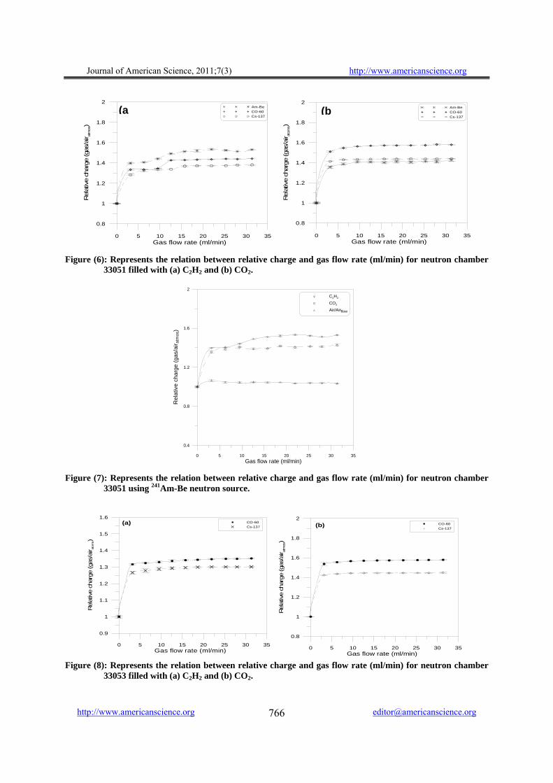
Figure (6a) shows the effect of gas flow rate on the charge of neutron chamber 33051 flushed with C2H2 gas flow, relative to the charge when the chamber was filled with atmospheric air for 241Am-Be, 60Co and 137Cs after a preflush with 100 cm3 C2H2.
It is clear from the figure that up to 1 ml/min, the increase in the sensitivity is proportional to the gas flow rate for all used radiation sources. In the region from 10 ml/min up to 12.5 ml/min slight dependence of the relative ionization chamber reading on gas flow rate. By increasing the gas flow rate up to about 13 ml/min the charge of the chamber remains rather constant. It can be seen that in the gas flow rate region from 13 ml/min to 31 ml/min the sensitivity of the ionization chamber can be increased by about 10 %, 8 % and 3 % for 241Am-Be, 60Co and 137Cs respectively.
Figure (6b) shows the effect of gas flow rate on the relative charge (gas/airatoms) of neutron chamber 33051 flushed with CO2 gas flow, for 241Am-Be, 60Co and 137Cs. The region from 12.5 ml/min to 31 ml/min the relative charge of chamber was more stable with increasing the gas flow rate. From the figure, it is clear that C2H2 gas gave higher sensitivity to detect neutrons than CO2 and air. This result shows the role of recoil protons in the C2H2 gas by fast neutrons. Moreover, the advantage of the use of C2H2 as filling gas in the neutron chambers is that it decreases the sensitivity of the chamber to detect gamma rays and increase its sensitivity for neutron detection, which is considered as one of the main objective of the present work.
Figure (7) shows the relation between relative charge (gas/airatoms) and the gas flow rate for neutron chamber 33051 in 241Am-Be neutron beam when the chamber was flushed with C2H2, CO2 and

Journal of American Science, 2011;7(3) http://www.americanscience.org
http://www.americanscience.org [email protected] 765
Figure (3): The relation between the relative charge and the cavity wall thickness for chamber 33051 filled
with atmospheric air at 60Co source (a) all thickness and (b) the extrapolation of the linear part. Figure (4): The effect of cavity thickness on the reading of the neutron ionization chamber 33051 in case of
CO2 gas flow and atmospheric air from 137Cs source. Figure (5): The relation between the relative charge and the cavity wall thickness for chamber 33051 at 137Cs
source filled with (a) atmospheric air and (b) CO2 gas.
0 2 4 6 8Cavity wall thickness (mm)
0.8
1
1.2
1.4
1.6
Rel
ativ
e ch
arge
(a
0 2 4 6 8 10Cavity wall thickness (mm)
1.09
1.095
1.1
1.105
1.11
1.115
Rel
ativ
e ch
arge
(b
0 2 4 6 8Cavity thickness (mm)
0.94
0.96
0.98
1
1.02
Rel
ativ
e ch
arge
Atmospheric airCO2 gas flow
0 2 4 6 8 10Cavity wall thickness (mm)
0.980
0.985
0.990
0.995
1.000
1.005
Rel
ativ
e ch
arge
(a)
0 2 4 6 8 10Cavity wall thickness (mm)
0.97
0.98
0.99
1.00
1.01
Rel
ativ
e ch
arge
(b
Journal of American Science, 2011;7(3) http://www.americanscience.org
http://www.americanscience.org [email protected] 766
Figure (6): Represents the relation between relative charge and gas flow rate (ml/min) for neutron chamber
33051 filled with (a) C2H2 and (b) CO2. Figure (7): Represents the relation between relative charge and gas flow rate (ml/min) for neutron chamber
33051 using 241Am-Be neutron source. Figure (8): Represents the relation between relative charge and gas flow rate (ml/min) for neutron chamber
33053 filled with (a) C2H2 and (b) CO2.
0 5 10 15 20 25 30 35Gas flow rate (ml/min)
0.8
1
1.2
1.4
1.6
1.8
2
Rel
ativ
e ch
arge
(gas
/air a
tmos)
Am-BeCO-60Cs-137
0 5 10 15 20 25 30 35Gas flow rate (ml/min)
0.8
1
1.2
1.4
1.6
1.8
2
Rel
ativ
e ch
arge
(gas
/air a
tom
s)
Am-BeCO-60Cs-137
(a (b
0 5 10 15 20 25 30 35Gas flow rate (ml/min)
0.4
0.8
1.2
1.6
2
Rel
ativ
e ch
arge
(gas
/air a
tmos
)
C2H2
CO2
Air/Airflow
0 5 10 15 20 25 30 35Gas flow rate (ml/min)
0.9
1
1.1
1.2
1.3
1.4
1.5
1.6
Rel
ativ
e ch
arge
(gas
/air a
tom
s)
CO-60Cs-137
(a)
0 5 10 15 20 25 30 35Gas flow rate (ml/min)
0.8
1
1.2
1.4
1.6
1.8
2
Rel
ative
char
ge (g
as/a
ir atm
os)
CO-60Cs-137
(b)

Journal of American Science, 2011;7(3) http://www.americanscience.org
http://www.americanscience.org [email protected] 767
air. It is clear from the figure that the maximum sensitivity of the neutron chamber 33051 for C2H2 gas whereas the minimum sensitivity for air/airflow. Up to 13 ml/min the sensitivity of the neutron chamber 33051 can be increased by about 10 %, 7 % and 4 % for C2H2, CO2 and air/airflow respectively. The ratio of the relative charge for chamber 33051 filled with atmospheric air to air flow rate is about 1.05 which is assumed to be only one. This finding may be due to the recombination reactions between O2 and N2 molecules forming atmospheric air which are kept in static form under strong electric field strength of 400 kV/m (applied voltage to the chamber is 400 V and the distance between the internal chamber electrodes is 4 mm). Nitric oxides may be generated within atmospheric air filling the chamber in static form condition under the influence of this strong electric field. These additional growing impurities in the filling air may be a reason for this increase of the chamber reading.
Figures (8 a and b) show the effect of gas flow rate on the relative charge (gas/airatoms) of neutron chamber 33053 using different gases (C2H2 and CO2) and 60Co and 137Cs sources. Comparing these figures with Figures (6 a and b), it can be seen that the two chambers have the same sensitivity when they were flushed with CO2 for two gamma sources. When the chambers were flushed with C2H2 gas, the sensitivity of neutron chamber 33051 is greater than the chamber 33053 with 38 % in the 60Co beam. In the 137Cs beam the sensitivity of the neutron chamber 33051 is less than the chamber 33053 with 2.8 %. Table (V) shows the values of gas flow rate for two neutron ionization chamber with different gamma sources and the percentage of standard deviation.
4.9.1 Radial Uniformity Correction Factor
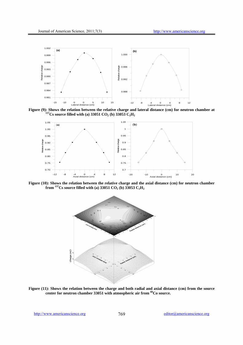
Figures (9 a and b) represent the radial beam non-uniformity over the cavity thickness in air for 33051 neutron ionization chamber flushed with CO2 gas and for 33053 neutron chamber flushed with C2H2 gas flow using 137Cs gamma beam. From the two figures it is clear that the cesium beam is symmetrical over the studied range. The deviation from the central field point (0,0) to the point ±12 cm is about 1.6 % for 33051 chamber and to the point ± 9 cm is about 1.2 % for 33053 neutron chamber. Beam uniformity is much more homogeneous at the field center.
4.9.2 Axial Uniformity Correction Factor
Figures (10 a and b) represent the axial beam non-uniformity over the cavity thickness in air for 33051 neutron ionization chamber flushed with CO2 gas and for 33053 neutron chamber flushed with
C2H2 gas using 137Cs gamma beam. From the two figures it is clear that the radiation beam is symmetrical over the studied range (±10 cm) in the case of chamber 33051, the deviation from the central field point (0,0) is about 4.24% upward and 4.97 % downward. The studied range in the case of chamber 33053 is (±15 cm), The maximum deviation from the central field point (0,0) is about 4.80 % upward and 5.55 % downward direction. Beam uniformity is noticeable at the field center.
Figures (11) and (12) represent the radiation contour pattern and wire frame mapping for both radial and axial uniformity for the two neutron ionization chambers 33051 and 33053 filled with air in cobalt beam. From the figures it is clear that the radiation beam is not symmetrical over the studied range (±5 cm). For the chamber 33051 filled with air, the deviation from the (0,0) point to the point ±5 cm for the radial direction was 2.7 % and 4.5 %, for axial direction was 3.2 % and 8.5 % for upward and downward direction.
For chamber 33053 the deviation from the (0,0) point to the point ± 5 cm for radial direction was 1.6 % and 2.7 %, for axial direction was 2 % and 6.6 % for upward and downward direction. Beam uniformity is remarkable at the field center. Table (VI) shows the values of Radial & Axial beam uniformity correction factor for two neutron ionization chambers.
4.10 Resultant Calibration of TE Neutron
Ionization chambers Table (VII) shows the results of whole
calibration coefficients in air in terms of air kerma (Nk) with unit mGy/nC in different radiation quality. Table (VIII) shows the calibration coefficients in water phantom in terms of absorbed dose to water (NDw) with unit mGy/nC experimentally and calculated using 137Cs and 60Co, experimental ratio NDw/Nk in cesium beam for neutron ionization chambers.
The experimental ratio NDw/Nk for a given neutron chambers give useful information about their uniformity. The usual situation for chambers calibrated only in air having air kerma factor (Nk), the absorbed dose to water factor (NDw) can be calculated using this ratio which based on a code of practice used. From Table (VII), it is clear that the values of air kerma (Nk) for both neutron chambers types 33051 and 33053 are energy and gas filling dependents.
Figures (13 a and b) illustrate the relation between the relative air kerma Nk normalized to cobalt beam and energies for different radiation quality for two NIS secondary standard ionization chambers (NPL and Farmer) and two neutron

Journal of American Science, 2011;7(3) http://www.americanscience.org
http://www.americanscience.org [email protected] 768
ionization chambers 33053 and 33051 with different gases. It is clear that the results of NPL and Farmer ionization chambers are nearly coincidence and energy independent. The neutron chambers with
different gases are not compatible at low X-ray energies while more consistency at higher energies, it is emphasized that energy dependent.
Table (V): The values of gas flow rate correction factor for the two neutron ionization chambers in 60Co and
137Cs beams. Flow rate correction factor &
Gas type %σ Source type Chamber type
Air C2H2 CO2 Air C2H2 CO2 33051 0.98154 0.99903 0.99993 0.02 0.070 0.007 60Co 33053 0.99849 0.99928 0.99973 0.01 0.030 0.020 33051 0.99991 0.99997 0.030 0.010 137Cs 33053 0.99941 1.00000 0.024 0.002
Table (VI): The values of Radial & Axial beam uniformity correction factors for two neutron ionization
chambers.
Table (VII): shows the calibration coefficients in terms of air kerma in X-ray beam, 137Cs and 60Co for
neutron ionization chambers. Nk, Neutron chamber type
33051 Nk, Neutron chamber type
33053 Air
static C2H2 CO2 Air static C2H2 CO2 Radiation quality
mGy/nC mGy/nC 100 kV 40.38 34.03 26.11 35.97 30.30 23.24 180 kV 35.45 28.72 23.09 32.04 25.82 20.74 X-
Ray 250 kV 33.75 26.34 22.23 30.82 24.01 20.25
137Cs 31.11 22.89 19.65 28.33 22.02 18.85 60Co 30.29 21.24 19.32 28.24 21.00 18.02
Table (VIII): shows the calibration coefficients in terms of absorbed dose to water in 137Cs and 60Co,
experimental ratio NDw/Nk in 137Cs beam for neutron ionization chambers.
Neutron chamber type 33051 Neutron chamber type 33053
NDw, Air static
NDw, C2H2
NDw, CO2
NDw, Air static
NDw, C2H2
NDw, CO2
Radiation quality Type of determination
mGy/nC mGy/nC Experimentally 35.85 27.52 24.74 35.13 27.42 24.42 137Cs
NDw/Nk 1.153 1.202 1.259 1.240 1.245 1.296
Radial beam uniformity correction factor & Gas type
Axial beam uniformity correction factor & Gas type Source
type Chamber
type Air C2H2 CO2 Air C2H2 CO2
33051 1.004 0.996 60Co 33053 0.997 1.006 33051 1.000 0.999 137Cs 33053 0.9997 1.004
Journal of American Science, 2011;7(3) http://www.americanscience.org
http://www.americanscience.org [email protected] 769
Figure (9): Shows the relation between the relative charge and lateral distance (cm) for neutron chamber at
137Cs source filled with (a) 33051 CO2 (b) 33053 C2H2 Figure (10): Shows the relation between the relative charge and the axial distance (cm) for neutron chamber
from 137Cs source filled with (a) 33051 CO2 (b) 33053 C2H2 Figure (11): Shows the relation between the charge and both radial and axial distance (cm) from the source
center for neutron chamber 33051 with atmospheric air from 60Co source.
-15 -10 -5 0 5 10 15Lateral distance (cm)
0.981
0.984
0.987
0.990
0.993
0.996
0.999
1.002
Rel
ativ
e ch
arge
(a)
-12 -8 -4 0 4 8 12Lateral distance (cm)
0.988
0.992
0.996
1.000
Rel
ativ
e ch
arge
(b)
-12 -8 -4 0 4 8 12Axial distance (cm)
0.70
0.75
0.80
0.85
0.90
0.95
1.00
1.05
Rel
ativ
e ch
arge
(a)
-20 -10 0 10 20Axial distance (cm)
0.7
0.75
0.8
0.85
0.9
0.95
1
1.05
Rel
ative
char
ge
(b)

Journal of American Science, 2011;7(3) http://www.americanscience.org
http://www.americanscience.org [email protected] 770
Figure (12): Shows the relation between the charge and both radial and axial distance (cm) from the source
center for neutron chamber 33053 with atmospheric air from 60Co source. Figure (13): Represents the relation between the relative air kerma (Nk) normalized to 60Co and radiation
energies for secondary standard 0.6 cm3 farmer and 0.3 cm3 NPL chambers and neutron chamber filled with different gases (a) 33053 and (b) 33051.
4.11 The Sensitivity of Neutron Chamber
Compared to Gamma Chamber Figures (13 a and b) show the relation
between collected charge and source -to-detector distance for neutron chamber 33051 compared with the secondary standard gamma ionization chamber (NPL chamber) normalized to its volume in 60Co and 137Cs beams.
The correction factors were 1.085 and 1.098, respectively for 60Co and 137Cs, for neutron chamber filled with atmospheric air. However, when the neutron chamber was flushed with C2H2 or CO2, the response was increased. The correction factors were 0.743 and 0.679, respectively in 60Co beam, in 137Cs beam they were 0.809 and 0.694, respectively.
0 300 600 900 1200 1500Energy (keV)
0.6
0.7
0.8
0.9
1
1.1
1.2
1.3
1.4
Rel
ativ
e N
k no
rmal
ized
to 60
Co
NIS 0.6 FarmerNIS 0.3 NPLAir 33053CO2 33053C2H2 33053
(a)
gy ( )
0 300 600 900 1200 1500Energy ( keV)
0.6
0.7
0.8
0.9
1
1.1
1.2
1.3
1.4
Rel
ativ
e N
k no
rmal
ized
to 60
Co
NIS 0.6 FarmerNIS 0.3 NPLAir 33051CO2 33051C2H2 33051
(b)
Journal of American Science, 2011;7(3) http://www.americanscience.org
http://www.americanscience.org [email protected] 771
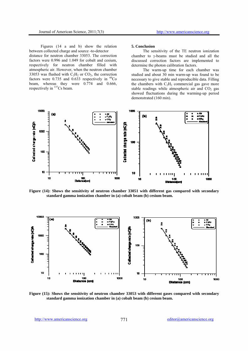
Figures (14 a and b) show the relation between collected charge and source -to-detector distance for neutron chamber 33053. The correction factors were 0.996 and 1.049 for cobalt and cesium, respectively for neutron chamber filled with atmospheric air. However, when the neutron chamber 33053 was flushed with C2H2 or CO2, the correction factors were 0.735 and 0.633 respectively in 60Co beam, whereas they were 0.774 and 0.666, respectively in 137Cs beam.
5. Conclusion The sensitivity of the TE neutron ionization
chamber to γ-beams must be studied and all the discussed correction factors are implemented to determine the photon calibration factors.
The warm-up time for each chamber was studied and about 30 min warm-up was found to be necessary to give stable and reproducible data. Filling the chambers with C2H2 commercial gas gave more stable readings while atmospheric air and CO2 gas showed fluctuations during the warming-up period demonstrated (160 min).
Figure (14): Shows the sensitivity of neutron chamber 33051 with different gas compared with secondary
standard gamma ionization chamber in (a) cobalt beam (b) cesium beam.
Figure (15): Shows the sensitivity of neutron chamber 33053 with different gases compared with secondary standard gamma ionization chamber in (a) cobalt beam (b) cesium beam.

Journal of American Science, 2011;7(3) http://www.americanscience.org
http://www.americanscience.org [email protected] 772
The results showed that the increase of wall thickness increased the sensitivity of the chamber to gamma radiation till a wall thickness of 3mm. High thickness did not show any more increase of the ionic current. This result indicates that the ions are emitted from the walls of the chamber resulting from the interaction with the gamma rays. At thickness higher than 3 mm self absorption of the emitted ions from the walls occur which prevents no more ions of reaching the chamber cavity. The neutron ionization chambers filled with C2H2 gas flow of 18.6 ml/min (as a tissue equivalent gas) can be used as a secondary standard for measuring neutron equivalent dose rates. It has the advantage of increasing the sensitivity of the chamber to detect fast neutrons and decreasing its sensitivity for gamma rays.
Corresponding author Arafa Abd El-Hafez Ionizing Radiation Metrology Laboratory (IRML), National Institute for Standards (NIS), Giza, Egypt. [email protected] 5. Reference: 1. Arbabi, K. Larijani M. M. Ramazanov, M. 2010.
Evaluation of a new ionisation chamber fabricated with carbon nanotubes. Radiation Protection Dosimetry, Vol. 141, No. 3, pp. 222–227.
2. Bichsel, H. and Rubach, A., 1978. Uncertainty of the determination of absolute neutron dose with ionization chambers. In Proceedings of the Third Symposium on Neutron Dosimetry in Biology and Medicine, EUR 5848, Ed. by G. Burger and H. G. Ebert. (Commission of the European Communities, Luxembourg), p. 549.
3. Boutillon M. and Allisy-Roberts S P., 1996. Measurement of Air Kerma and Ambient Dose Equivalent in Cs-137 Beam, Report BIPM – 96/7.
4. Boutillon M. and Perroche A.M., 1989. Radial non Uniformity of BIPM Co-60 Beam, Report BIPM – 89/2.
5. Boutillon, M. and Perroche, A. M., 1985. Effect of a change of stopping-power values on the W value recommended by ICRU for electrons in dry air, Document CCEMRI (I)/85-8 in BIPM Com. Cons. Etalons Mes. Ray. Ionisants, (Section I) (Bureau International des Poids et Mesures, Sevres, France) see also: Phys. Med. Biol. 32, 213.
6. Broerse, J. J., Mijnheer, B. J., and Williams j. r., 1981. European protocol for neutron dosimetry for external beam therapy. British Journal of Radiology, 54, 882.
7. Caswell, R. S. and Coyne, J. J., 1972. Interaction of neutrons and secondary charged particles with tissue: secondary particle spectra. Radiat. Res., 52, 448.
8. Ferreira, C.C. Ximenes Filho, R.E.M., Vieira, J.W. Tomal, A. Poletti, M.E. Garcia, C.A.B. Maia, A.F. 2010. Evaluation of tissue-equivalent materials to be used as human brain tissue substitute in dosimetry for diagnostic radiology. Nuclear Instruments and Methods in Physics Research B 268 2515–2521.
9. IAEA, 1984. Panel proceedings series, Advances in dosimetry for fast neutrons and heavy charged particles for therapy applications, International Atomic Energy Agency, Vienna.
10. IAEA, 1994. Technical Report Series No. 374, Calibration of dosimeters used in radiotherapy, International Atomic Energy Agency, Vienna.
11. IAEA, 2000. Technical Report Series No. 398, Absorbed dose determination in external beam radiotherapy, International Atomic Energy Agency, Vienna.
12. ICRU, 1989. Clinical neutron dosimetry part I: Determination of absorbed dose in a patient treated by external beams of fast neutrons. Report 45, (International Commission on Radiation Units and Measurements, Washington, DC).
13. ICRU, 1992. Phantom and computational models in therapy, diagnosis and protection. Report 48, (International Commission on Radiation Units and Measurements, Washington, DC).
14. Juan G. Miranda, Paul M. DeLuca, Jr Mark B. Chadwic. 2004. Ion chamber gas-to-wall conversion factors for fast neutron dosimetry. Radiation Protection Dosimetry , Vol. 110, Nos 1-4, pp. 15-25.
15. Kessler, C. Allisy-Roberts, P., McCaffrey, J., Ross, C. 2010. Comparison of the standards for air kerma of the NRC and BIPM for Co-60 gamma radiation. BIPM report (final report for NRC – 2010 - 01 -11).
16. Lindborg, L. and Nikjoo, H. 2004. Ion chamber gas-to-wall conversion factors for fast neutron dosimetry. Radiation Protection Dosimetry , (110), Nos 1-4, pp. 15-25.
17. Mijnheer, B. J. and Williams, J. R., 1981. Determination of absorbed dose and kerma in a neutron field from measurements with a tissue-equivalent ionization cham-ber. Phys. Med. Biol., 26, 57.
18. Niatel, M.T., Loftls, T. P. and Oetzmann, W., 1975. Comparison of exposure standards for 60Co gamma-rays. Metrologia, 11. 17.
19. Oliver Ja¨kel. 2009. Medical physics aspects of particle therapy. Radiation Protection Dosimetry (2009), Vol. 137, No. 1–2, pp. 156–166.
20. Philips, 1998. High stability constant potential x-ray systems. Service Manual, Philips Industrial X-ray Gmbh, Hamburg, Germany.
21. Podgorsak, E. B., 2005. Review of radiation oncology physics: A handbook for teachers and students. International Atomic Energy Agency, Vienna, Austria.
22. Pszona, S. 2010. On the true sensitive volume of ionization chambers applied for particle beam dosimetry. Radiation Measurements 45 - 1449e1451.
23. Ruedi Risler and Alina Popescu, 2010. Dosimetry measurements at the fast neutron therapy facility in Seattle. Radiation Measurements 45 1452-1454.
24. Williams, j. r. and Greening, j. r., 1980. The photon calibration of a tissue – equivalent ionization chamber for neutron dosimetry. Phys. Med. Biol., 25(2), 215.
25. Wojciech Bulski Piotr Ulkowski, Barbara Gwiazdowska, Joanna Rostkowska. 2008. An analysis of calibration coefficients measured in water and in air for Farmer-type cylindrical ionization chambers. Pol J Med Phys Eng. 14(2):113-121.
26. Yanxiao Huang Christian Willomitzer, Golam Abu Zakaria, Guenther H. Hartmann. 2010. Experimental determination of the effective point of measurement of cylindrical ionization chambers for high-energy photon and electron beams. Physica Medica, 26, 126-131.
27. Zhe Chen, Francesco d’Errico, Ravinder Nath. 2007. Principles and requirements of external beam dosimetry. Radiation Measurements 41, S2–S21.
28. Zoetelief, J. and Broerse, J. J., 1983. Dosimetry with tissue-equivalent ionization chambers in fast neutron fields for biomedical applications. Phys. Med. Biol., 28 (5), 503.
2/1/2011