evaluation of co2 flooding in multi-layered heterogeneous...
TRANSCRIPT

Petroleum Technology 63
1. INTRODUCTION As oil demand is growing globally, together
with limited recoverable resources, Enhanced Oil Recovery (EOR) is then viewed to help increase oil recovery from reservoir. Among techniques used in EOR, Carbon dioxide (CO2) flooding has been commercially proven and has been broadly used as a promising approach. In addition, the use of CO2 is not only considered as an EOR injected fluid to improve oil recovery but can be adopted to sequestering emitted greenhouse gas. CO2 flooding can be implemented either immiscible or miscible modes, depending on oil property, purity of CO2 injected, reservoir conditions, and operational conditions. In CO2 miscible flooding, miscibility can be achieved through Multi-Contact Miscibility (MCM) by means of evaporating of intermediate compounds (C2-C6) in reservoir oil by CO2. Besides, reservoir pressure has to be greater than Minimum Miscibility Pressure (MMP) in order to achieve the miscibility between CO2 and reservoir oil.
By means of CO2 flooding, an increment of oil recovery is mainly attained by improvement of displacement efficiency. The mechanisms contributing to enhannce recovery of CO2 flooding are oil viscosity reduction, oil swelling and IFT reduction [1]. CO2 miscible flooding has been reportedly desirable because it is applicable with wide range of oil properties, can reach MMP at relatively low pressure compared to other miscible gases [2] and can be applied in both sandstone and carbonate formations [1][3]. Lower density of CO2 compared to oil, however, can cause gas overriding and consequently an early breakthrough of the injected CO2, causing preceded CO2 production prior to oil production.
Large amount of oil is upswept and low oil recovery is obtained accordingly. Such these problems, CO2 is generally implemented in an inclined reservoir, displacing oil by CO2 injection from updip location. Early gas breakthrough is then mitigated by gravity effect. Not only inclination of reservoir that plays a role in most gas injection, heterogeneity of reservoir, referring to variation of petrophysical properties mainly permeability, has been also identified as an important factor affecting gas displacement performance. Presence of high permeability streaks typically leads to gas channeling, resulting in gas early breakthrough. This literally draws instability of flood front, and therefore creates disappearance of miscible bank. 2. RESERVOIR SIMULATION MODEL Compositional simulator ECLIPSE®300 is the tool used in order to evaluate effects from various studied parameters. Initial base case model is constructed by simple Cartesian coordinate to represent a 10-layer homogeneous and horizontal reservoir with its total size of 840×5000×200 ft in x, y and z, respectively. Injector and producer are located at the middle of each reservoir side, and opposite to each other, so that distance between these two well is 5,000 ft as depicted in Figure 1.
Fig. 1 3-D view of base case reservoir model
ABSTRACT Carbon dioxide (CO2) flooding is recognizably exploited to enhance oil recovery, acheiving through
miscibility mechanism between CO2 and reservoir oil. Since CO2 is less dense compared to reservoir oil, this leads to gas overriding and instability of flood front, especially when applied in heterogeneous reservoir, resulting in poor recovery efficiency. This study aims to investigate effects of uncontrollable parameters including reservoir heterogeneity, depositional sequence and dip angle. Appropriate conditions combined with controllable parameters including CO2 injection rate and CO2 injection perforation interval are also studied. Heterogeneous reservoir model is quantitatively determined by Lorenz coefficient (Lc). Compositional reservoir simulator ECLIPSE®300 is utilized throughout the study. KEY WORDS: CO2 Flooding / Miscible Flooding / Heterogeneous Reservoir / Multi-Layered Reservoir
S. Summapo1*, F. Srisuriyachai1, S. Athichanagorn1 1Department of Mining and Petroleum Engineering, Chulalongkorn University, Thailand
*e-mail: [email protected]
PPaappeerr IIDD 112244
Evaluation of CO2 Flooding in Multi-Layered Heterogeneous Reservoir
Petroleum Technology 64
Reservoir wetting preference is considered as water-wet. For oil-water system, connate water saturation (Swc) and residual oil saturation (Sorw) are 0.28 and 0.24, respectively. For oil-gas system, residual oil saturation (Sorg) and critical gas saturation (Sgc) are 0.15 and 0.1, respectively. These parameters are then inserted into model using Corey's correlation with software default exponents to generate two sets of relative permeability. Other reservoir properties are also provided in Table 1. Initial fluid composition is summarized in Table 2. With these components, physical properties for each one can be generated using PVTi before exported to compositional simulator. Tab. 1 Details of reservoir model
Parameter Value Unit Effective Porosity (ϕ) 20 % Horizontal permeability (kh) 150 mD Vertical permeability (kv) 0.1kh mD Top of reservoir 5,000 ft Initial reservoir pressure (Pi) 2,512 psia Initial reservoir temperature 172 oF Bubble point pressure (Pb) 2,375 psia
Tab. 2 Initial fluid composition
Component Mole
fraction (%)
Carbon dioxide CO2 0.91 Nitrogen N2 0.06 Methane C1 33.83 Ethane C2 9.04
Propane C3 7.99 iso-Butane i-C4 1.97
normal-Butane n-C4 4.69 iso-Pentane i-C5 3.6
normal-Pentane n-C5 1.78 Hexane C6 5.01
Heptane plus C7+ 31.12 Specific gravity of C7+ 0.8615
Molecular weight of C7+ 267 It is suggested that to achieve miscible condition, reservoir pressure must be greater than Minimum Miscibility Pressure (MMP). The estimated MMP is found to be 3,067 psia as an average value calculated from four published correlations, principally based on reservoir fluid properties and reservoir temperature [4][5][6][7]. For further study, the model is built to represent heterogeneous reservoir where permeability is varied. Each model is assigned with a heterogeneity index, called Lorenz coefficient (Lc). Varying permeability value in vertical direction between 20-300 mD, as a min-max boundary, can make up five different Lorenz coefficients covering 0.18, 0.25, 0.32, 0.38 and 0.44. The permeabilty data is set to have average
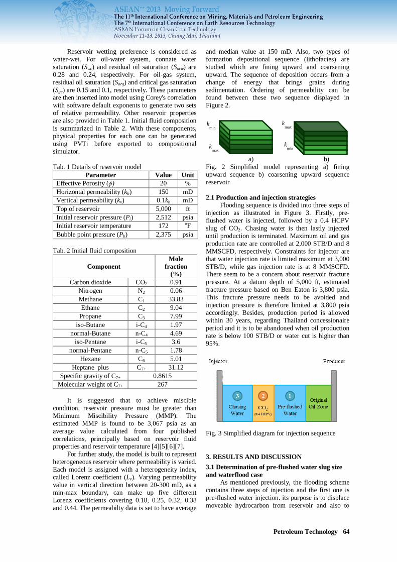
and median value at 150 mD. Also, two types of formation depositional sequence (lithofacies) are studied which are fining upward and coarsening upward. The sequence of deposition occurs from a change of energy that brings grains during sedimentation. Ordering of permeability can be found between these two sequence displayed in Figure 2. a) b) Fig. 2 Simplified model representing a) fining upward sequence b) coarsening upward sequence reservoir 2.1 Production and injection strategies Flooding sequence is divided into three steps of injection as illustrated in Figure 3. Firstly, pre-flushed water is injected, followed by a 0.4 HCPV slug of CO2. Chasing water is then lastly injected until production is terminated. Maximum oil and gas production rate are controlled at 2,000 STB/D and 8 MMSCFD, respectively. Constraints for injector are that water injection rate is limited maximum at 3,000 STB/D, while gas injection rate is at 8 MMSCFD. There seem to be a concern about reservoir fracture pressure. At a datum depth of 5,000 ft, estimated fracture pressure based on Ben Eaton is 3,800 psia. This fracture pressure needs to be avoided and injection pressure is therefore limited at 3,800 psia accordingly. Besides, production period is allowed within 30 years, regarding Thailand concessionaire period and it is to be abandoned when oil production rate is below 100 STB/D or water cut is higher than 95%.
Fig. 3 Simplified diagram for injection sequence
3. RESULTS AND DISCUSSION 3.1 Determination of pre-flushed water slug size and waterflood case As mentioned previously, the flooding scheme contains three steps of injection and the first one is pre-flushed water injection. its purpose is to displace moveable hydrocarbon from reservoir and also to
kmax
kmin
kmin
kmax

Petroleum Technology 65
improve displacement efficiency through a reduction of permeability contrast in reservoir. Optimization of pre-flushed water slug size is, therefore, determined by varying its slug size including 0.05, 0.1, 0.15, 0.2 and 0.25 PV. The plot between pre-flushed water slug sizes versus oil recovery in Figure 4 indicates that 0.2 PV is the optimal value to be applied with initial flooding base case because it shows significant improvement on oil recovery compared to lower slug size. Enlarging water slug size could improve oil recovery by maintaining longer maximum oil production period and also total production period but it is found that slug size of 0.25 PV is too big as large amount of water starts arriving at producer (Figure 5a), visibly reducing relative permeability to oil so that oil production rate falls for a while during this arrival of water as shown in Figure 5b. Thus, oil recovery increment is not significant. For the next step, determined flooding sequence with 0.2 PV of water slug size is therefore kept as a base case. Moreover, waterflood case is also performed in order to ensure that proposed CO2 miscible flooding scheme is able to provide better oil recovery and results shows that 68% oil recovery can be achieved from the base case and it is 8% higher than performing only waterflood mainly due to an improvement in displacement efficiency (microscopic). CO2 flooding base case also delivers this higher recovery within shorter period compared to the waterflood case.
Fig. 4 Oil recoveries as a function of pre-flushed water slug size 3.2 Effect of study parameters Parameters to be investigated in this part include reservoir dip angle, CO2 injection rate and CO2 injection perforation interval. In each parameter, reservoir is modeled with all configurations and controls identically to the base case, except reservoir heterogeneity, specified by Lorenz coefficient due to the fact that reservoir heterogeneity is one of concerns which typically impact flow characteristic and so the oil recovery, especially when reservoir is produced through gas injection. In addition, two different lithofacies including fining upward and coarsening upward are also varied with the base case.
Fig. 5a Oil production rates for determination of slug size of pre-flushed water
Fig. 5b Water production rates for determination of slug size of pre-flushed water 3.2.1 Reservoir dip angle Inclination of reservoir is considered as an important uncontrollable parameter because it might assist stability of displacement mechanism due to gravity segregation effect when performing gas injection at updip location. Heterogeneous reservoir models employed with dip angle of 0, 15, 30 and 45 degree are studied. Results of oil recovery when varying heterogeneity index on each reservoir dip angle for both lithofacies are plotted in Figures 6a and 6b respectively.
Fig. 6a Oil recovery on different reservoir dip angles on fining upward model
Petroleum Technology 66
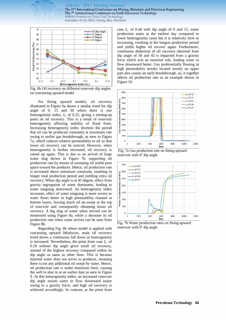
Fig. 6b Oil recovery on different reservoir dip angles on coarsening upward model For fining upward models, oil recovery illustrated in Figure 6a shows a similar trend for dip angle of 0, 15 and 30 where there is one heterogeneity index, Lc of 0.25, giving a turning-up point on oil recovery. This is a result of reservoir heterogeneity affecting stability of flood front. Increasing heterogeneity index shortens the period that oil can be produced constantly at maximum rate owing to earlier gas breakthrough, as seen in Figure 7a, which reduces relative permeability to oil so that lower oil recovery can be noticed. However, when heterogeneity is further increased, oil recovery is raised up again. This is due to an arrival of large water slug shown in Figure 7b, supporting oil production rate by means of sweeping oil inside pore space toward the producer. Hence, oil production rate is increased above minimum constraint, resulting in longer total production period and yielding extra oil recovery. When dip angle is at 45 degree, effect from gravity segregation of water dominates, leading to water tonguing downward. As heterogeneity index increases, effect of water tonguing is more severe as water flows better in high permeability channel at bottom layers, leaving much oil un-swept at the top of reservoir and consequently obtaining lesser oil recovery. A big slug of water when arrived can be monitored using Figure 8a, while a decrease in oil production rate when water arrives can be seen from Figure 8b. Regarding Fig. 6b where model is applied with coarsening upward lithofacies, main oil recovery trend shows a continuous fall down as heterogeneity is increased. Nevertheless, the point from case Lc of 0.18 without dip angle gives small oil recovery, instead of the highest recovery compared within its dip angle as same as other lines. This is because injected water does not arrive to producer, meaning there is not any additional oil swept by water. Hence, oil production rate is under minimum limit, causing the well to shut in at an earlier date as seen in Figure 9. At this heterogeneity index, an increased reservoir dip angle assists water to flow downward easier owing to a gravity force; and high oil recovery is achieved accordingly. In contrast, at the point from
case Lc of 0.44 with dip angle of 0 and 15, water production starts at the earliest day compared to lower heterogeneity cases but it is relatively slow in increasing, resulting in the longest production period and yields higher oil recover again. Furthermore, continuous deduction of oil recovery obtained from dip angle of 30 and 45 is impacted from a gravity force which acts an essential role, leading water to flow downward better. Gas preferentially flowing in high permeability streaks located mostly on upper part also causes an early breakthrough, so, it together affects oil production rate as an example shown in Figure 10.
Fig. 7a Gas production rate on fining upward reservoir with 0o dip angle
Fig. 7b Water production rates on fining upward reservoir with 0o dip angle

Petroleum Technology 67
Fig. 8a Gas production rate on fining upward reservoir with 45o dip angle
Fig. 8b Water production rates on fining upward reservoir with 45o dip angle
Fig. 9 Oil production rate with 0o angle on coarsening upward model 3.2.2 CO2 injection rate Reservoir pressure can be raised by means of CO2 injection due to its high compressibility. Reservoir pressure is one of key parameters controlling displacement efficiency. Pressure must be higher than MMP in order to create miscibility. It might be said that the higher the reservoir pressure, the more chance of miscible bank to be formed. This considerably leads to an improved performance in oil recovery.
Fig. 10 Oil, water and gas production rate for Lc of 0.44 with 45o dip angle on coarsening upward model CO2 injection rate which is interrelated to injection pressure is therefore studied in this part. Two additional injection rate of lower (6 MMSCFD) and higher (10 MMSCFD) deviated from the medium injection rate (8 MMSCFD) from the base case are studied and variation of heterogeneity index together with lithofacies is also applied in this section. Although injection rate of CO2 is changed, the designed CO2 slug size is still fixed at 0.4 HCPV. The simulation results of oil recovery as a function of reservoir heterogeneity index for the study of CO2 injection rate are plotted in Figures 11a and 11b.
Fig. 11a Oil recovery on different CO2 injection rate on fining upward model From Figure 11a, it is likely that these three injection rate give a similar trend of oil recovery for fining upward reservoir model, at which there exists a turning point to get a bounce up of oil recovery. However, for the case of injection rate of 10 MMSCFD, if the prior heterogeneity index is available, the first point on the plot of this trend may be clearly considered as a turning point as well. Though, these trends are quite similar, the turning point or point having the lowest oil recovery is located at different heterogeneity index. The reason on recovery is the same as mentioned in the previous effect but the difference is from a breakthrough of a big slug of water in each injection rate. Production of

Petroleum Technology 68
a large amount of water can explain this situation. For example, at the heterogeneity index of 0.25, a big gap of oil recovery between cases can be found and this is because only the case of 10 MMSCFD can produce a significantly huge amount of water compared to lower injection rate as illustrated in Figure 12a. Likewise, oil recovery at the heterogeneity index of 0.32 follows the same behavior and this is shown in Figure 12b. The reason that water is produced differently even heterogeneity index is the same is that higher CO2 injection rate results in an earlier date to complete a CO2 slug size of 0.4 HCPV shown in Figure 13, as a designed value, so that chasing water is injected earlier, aiding larger amount of water production at the right time.
Fig. 11b Oil recovery on different CO2 injection rate on coarsening upward model Considering oil recovery from coarsening upward model in Figure 11b, it gives a similar trend from each CO2 injection rate as well. However, it is remarked that there are two points differentiated from the trend but it is still obvious that increasing injection rate provides a better performance on oil recovery. The first point can be observed is from the case Lc of 0.18. Oil recovery from all injection rates should approximately get the same value because the effect from water support does not reveal due to the fact that low variation of permeability together with coarsening lithofacies enables waterflood front to be stable. However, the case with injection rate of 10 MMSCFD shows higher oil recovery which is obtained from extension of total production period. This is an outcome from an arrival of big slug of water because high injection rate means early finish of planned CO2 slug size and so early chasing water injection is also attained accordingly. The adverse effect of water production can be used to explain another point which is from the case Lc of 0.32 with CO2 injection rate of 6 MMSCFD. It can be noticed from this case that significantly lower oil recovery is obtained.
Fig. 12a Water production rates on different injection rates for Lc of 0.25on fining upward
Fig. 12b Water production rates on different injection rates for Lc of 0.32 on fining upward
Fig. 13 Actual CO2 injection rates for Lc of 0.25 on fining upward model 3.2.3 CO2 injection perforation interval When CO2 is injected into reservoir it might easily flow in high permeability streaks. Since CO2 is gas, it possesses high mobility. Low gravity of gas may also cause severe gravity segregation, leaving much oil remained unswept inside reservoir and impoverished performance is found accordingly. The study in this section is to determine the effect from partial injection of CO2 through the injector into the location away from high permeability zone. For example, the model, simulated with fining upward

Petroleum Technology 69
sand where high permeability channel is located at lower part of reservoir, is to be partially injected with CO2 only at upper part. The base case is to be applied with other two partial injection intervals of CO2, 50% and 75%. CO2 slug size of 0.4 HCPV is still remained constant for every model in this part. The simulation outcomes are plotted in Figures 14a and 14b for fining upward and coarsening lithofacies, respectively.
Fig. 14a Oil recovery from different CO2 injection perforation interval on fining upward model
Fig. 14b Oil recovery from different CO2 injection perforation interval on coarsening upward model Apparently, no difference on oil recovery from varying injection interval of CO2 and varying heterogeneity index is noted for both fining upward and coarsening upward sand model. This is due to the fact that gas still show the same injection behavior such as amount of CO2 and finishing period of gas injection even the interval is shortened. The amount of oil from fining upward model can be produced higher than coarsening upward model. The reason is that coarsening upward model creates more unstable flood front from gas which leads to the larger area unswept by the miscible bank. It can be inferred that partial interval of CO2 injection does not show any significant effect on oil recovery. This could be due to the gas mobility that is extremely high and when it is combined with reservoir connectivity between each layer (vertical
permeability), gas then tends to flow only in high permeability zone, resulting in no difference between the cases. 3.3 Miscibility formation It is claimed that miscible bank is created in all study cases. Formation of the miscible bank is, thus, discussed in this section by using an example from the base case. CO2 is a vaporizer. It vaporizes light to intermediate hydrocarbons from oil into its gas phase, leaving heavy compounds in oil phase, causing oil to be more viscous. Viscosity increment of oil can be used to indicate the zone at which miscible bank is created as illustrated in Figure 15. This bank could extract a significant amount of trapped oil as seen from lower oil saturation after the miscible bank moves pass pore spaces. Besides, gas viscosity can also be used to confirm the formation of miscible bank as well. Theoretically, viscosity of gas phase is reduced when composition of paraffinic hydrocarbons increases. As CO2 is injected, vaporized hydrocarbon which is obtained from contacting with CO2 goes into the miscible phase; hence, low viscosity of the miscible bank can be seen. Figure 16 depicts gas viscosity after CO2 is injected.
Fig. 15 Reservoir profile a) oil viscosity b) oil saturation at different time step
a) b)
Fig. 16 Gas viscosity at a) 6 years after CO2 injected b) 4 years after chasing water injected

Petroleum Technology 70
As mentioned, miscible bank could draw its advantage when reservoir pressure is greater than MMP. Figure 17 points toward reservoir pressure during the date of CO2 injection and it is found that this period has reservoir pressure higher than MMP. Though, at the late period, reservoir pressure falls under this MMP, the monitored oil viscosity in Figure 15 confirms that miscibility can be maintained until it arrives to producer.
Fig.16 Base case reservoir pressure as a function of time 4. CONCLUSIONS 1) Reservoir heterogeneity affects CO2 miscible
flooding performance. Increasing heterogeneity causes higher unstable flood front and an early breakthrough of injected material can frequently occur. However, this early breakthrough is considered as either positive or negative results where gas shortens the maximum oil production rate, whereas water helps extend the production period by increasing the oil production rate to be above the minimum constraint. In addition, formation depositional sequence also plays a role in impacting the flow path preference. Thus, oil is swept depending upon this path.
2) Dip angle assists gravity segregation of CO2 by forming more stable flood front, resulting in retarding of breakthrough of gas. Hence, higher oil recovery is accomplished.
3) Higher CO2 injection rate yields benefit through accelerating the completion of 0.4 HCPV slug size.
4) CO2 injection perforation interval does not show any difference on the performance of this studied flooding.
ACKNOWLEDGEMENTS The results presented in this paper are part of Master’s degree study at Department of Mining and Petroleum Engineering, Faculty of Engineering, Chulalongkorn University. Authors would like to thank Chevron Thailand Exploration and Production, Ltd. who provides financial support for this study.
REFERENCES [1] M. Enayati, E. Heidaryan, and B. Mokhtari
(2008), New Investigations into Carbon Dioxide Flooding by Focusing on Viscosity and Swelling Factor Changes, presented at the Canadian International Conference/ SPE Gas Technology Symposium 2008, Calgary, Alberta, Canada, 17-19 June, 2008, Paper No. 2008-064.
[2] S. Majidaie, A. Khanifar, M. Onurand Tan, and I. M. Tan, A Simulation Study of Chemically Enhanced Water Alternating Gas (CWAG) Injection, presented at SPE EOR Conference at Oil and Gas West Asia, Muscat, Oman, 16-18 April, 2012, Paper No. SPE 154152.
[3] P.Y. Zang, S. Huang, S. Sayegh, and X.L. Zhou, Effect of CO2 Impurites on Gas-Injection EOR Process, presented at the 2004 SPE/DOE Fourteenth Symposium on Improved Oil Recovery, Tulsa, Oklahoma, USA, 17-21 April, 2004. Paper No. SPE 89477.
[4] W.F. Yelig, and R.S. Metcalfe, Determination and Prediction of CO2 Minimum Miscibility Pressures, Journal of Technology, 1980, Paper No. SPE 7477.
[5] H. Yuan, R.T. Johns, A.M. Egwuenu, and B. Dindoruk, Improved MMP Correlations for CO2 Floods Using Analytical Gas Flooding Theory, presented at the SPE/DOE Fourteenth Symposium on Improved Oil Recovery, Tulsa, Oklahoma, USA, 17-21 April, 2004, Paper SPE 89359.
[6] O. Glasø, Generalized Minimum Miscibility Pressure Correlation, SPE Journal, 1985. Paper No. SPE 12893.
[7] C. Cronquist, Carbon Dioxide Dynamic Miscibility with Light Reservoir Oils. Fourth Annual U.S. DOE Symposium on Enhanced Oil and Gas Recovery and Improved Drilling Methods, Tulsa, 1977.