evaluation and examination of temporary second line
TRANSCRIPT

Evaluation and examination of temporary second
line evacuation methods of the DolWin Beta
Bachelor thesis written at
Høgskolen Stord/Haugesund - Department of Marine Studies
Written by
Name: Johan Abrahamsson Cand. Nr. 12
Name: Gustav Lanzing Cand. Nr. 20

Dette arbeidet er gjennomført som ledd i bachelorprogrammet i nautikk ved Høgskolen Stord/Haugesund og er
godkjent som sådan. Godkjennelsen innebærer ikke at HSH innestår for metodene som er anvendt, resultatene
som er fremkommet og konklusjoner og vurderinger i arbeidet.
Haugesund Våren 2013
Evaluation and examination of temporary second line evacuation methods of
the DolWin Beta
Johan Abrahamsson Gustav Lanzing
----------------------------- -------------------------------
Navn på veileder: Bjarne Vandeskog
Gradering: Offentlig.

i
Foreword
This thesis was written as a part of the Bachelor of Maritime Studies programme at
Høgskolen Stord/Haugesund. The theme of the thesis was suggested by personnel at Aibel AS
in Haugesund.
Several persons have supported us throughout the process of writing the thesis. Without their
support it would not have been possible for us to produce it.
We would like to thank:
Bjarne Vandeskog – Veiledare, Høgskolen Stord/Haugesund
Helle Oltedal – Veiledare, Høgskolen Stord/Haugesund
Cathrine Bendiksen – Aibel AS
Jon Sletteskog – Aibel AS
Espen Flatene – Aibel AS
Svein Bunes – Aibel AS
As well as the people who were interviewed

ii
Index
Foreword .............................................................................................................................................i
Index .................................................................................................................................................. ii
Summary ........................................................................................................................................... iv
1 Introduction ................................................................................................................................1
1.1 History of Platform accidents during tow operation ...........................................................1
2 Context for research focus ..........................................................................................................3
2.1 Research Question .............................................................................................................3
2.2 Limitations and assumptions ..............................................................................................3
3 Theory ........................................................................................................................................4
3.1 The Swiss Cheese Model and barrier theory .......................................................................4
3.2 Event tree ..........................................................................................................................6
4 Method .......................................................................................................................................7
4.1 Research design .................................................................................................................7
4.1.1 Interviews ......................................................................................................................8
4.2 Limitations .........................................................................................................................9
4.2.1 Literature review ...........................................................................................................9
4.2.2 Interviews .................................................................................................................... 10
5 Findings .................................................................................................................................... 10
5.1 Conditions, platform design, POB ..................................................................................... 10
5.2 Platform design ................................................................................................................ 10
5.3 The Tow ........................................................................................................................... 11
5.4 Rules and regulations ....................................................................................................... 13
5.5 Non-suitable evacuation methods .................................................................................... 15
5.5.1 Davit launch able life rafts ............................................................................................ 15
5.5.2 Slide ............................................................................................................................. 16
5.5.3 Freefall lifeboat ............................................................................................................ 16
5.5.4 Chute and rappelling from boat landing platform ......................................................... 16

iii
5.6 Chute, rappelling and ladder ............................................................................................ 17
5.6.1 Why these methods? ................................................................................................... 17
5.6.2 Evacuation method #1: Evacuation chute ..................................................................... 17
5.6.3 Review of the Chute ..................................................................................................... 18
5.6.4 Event Tree for evacuation by chute .............................................................................. 20
5.6.5 Evacuation method #2: Rappelling ............................................................................... 21
5.6.6 Review of Rappelling .................................................................................................... 21
5.6.7 Events presented schematically of evacuation by rappelling ........................................ 23
5.6.8 Evacuation method #3: Ladder to the pontoons ........................................................... 24
5.6.9 Review of evacuation ladder ........................................................................................ 24
5.6.10 Events presented schematically of evacuation by ladder .......................................... 25
6 Discussion ................................................................................................................................. 26
6.1 Advantages of the chute .................................................................................................. 26
6.2 Disadvantages of the chute .............................................................................................. 27
6.3 Advantages of rappelling .................................................................................................. 28
6.4 Disadvantages of rappelling ............................................................................................. 29
6.5 Advantages of the evacuation ladder ............................................................................... 30
6.6 Disadvantages of the evacuation ladder ........................................................................... 30
6.7 Comparison of the evacuation methods ........................................................................... 31
6.7.1 Which method makes people feel the safest? .............................................................. 31
6.7.2 Simplicity and safety .................................................................................................... 31
6.7.3 Handling injured people ............................................................................................... 32
6.7.4 Physical layout of the DolWin Beta ............................................................................... 32
7 Conclusion ................................................................................................................................ 33
8 References .................................................................................................................................. I

iv
Summary This project explores different means of temporary secondary evacuation that could be used
for the wind platform the DolWin Beta during the towing from Haugesund to the German
Bight. The platform is extraordinarily tall, 90 meters from top to bottom, and a secondary
evacuation method for the personnel on board is needed if an accident would occur.
Based on reports from earlier tow operations, design drawings, interviews and research from
manufactures this report focuses three different evacuation methods were found to be most
suitable for the DolWin Beta platform: an evacuation chute, rappelling and ladders. These
methods are evaluated in relation to technical design, simplicity, safety, how well it could
handle injured personnel and how people would react when using it.
After evaluating the different temporary second line evacuations for the DolWin Beta the
authors have concluded that rappelling is the most suitable system due to its capability of
handling injured personnel, the flexibility of evacuation points and that personnel responsible
for the evacuation will be provided.

1
1 Introduction
A large wind platform called the DolWin Beta will be outfitted in Haugesund by the company
Aibel AS, (www.aibel.no). It will be towed from Haugesund to the German Bight in August
2014 where it is to be lowered to the seabed. During the tow the height of the platform will be
significantly higher than when standing in its final position.
It was when preparing for the tow of the DolWin Beta wind platform the problem concerning
the temporary second line evacuation of the 28 people that will be present emerged. During
tow from Haugesund to the German Bight, the platform will have a height (90 meters from
top to bottom) and a velocity (5 knots) that will disable the evacuation methods intended for
the platform while seated on the seabed.
The lack of precise rules or regulations that state how a second line evacuation is to be carried
out during a tow phase of a wind platform contributes to the present challenge and finding a
temporary second line evacuation for this specific tow could be a great beginning in a process
of evacuation standardization for similar operations in the future.
1.1 History of Platform accidents during tow operation
The history of accidents involving rigs that have sunk strongly suggests that the weather is the
greater risk factor and the weather in the North Sea is infamous for being rough. The
oceanographic phenomena called “freak waves” have also been recorded in modern times.
One of these hit the oil platform Draupner in 1995, (Paul H Tylor, 1995), at a time when the
significant wave height was 12 meters. Suddenly a wave with a height of 25.6 meters hit the
platform. Even though the platform wasn’t damaged by the way such waves carry a
tremendous force and one can only imagine the impact on an unprepared vessel or structure
during a tow operation.
Rigs under towing are particularly vulnerable because they are not fixed to the bottom of the
ocean. Normally the rigs are floating higher then their installation height for easier movement
and transportation. This changes the center of gravity and the stability of the structure and the
risk of capsizing increases, (Inge Tellnes, 2008).
During a tow operation the platform is connected to the towing vessels with heavy wires
mounted from the rig to the stern of the vessels. There is a risk that these wires snap leaving

2
the platform floating uncontrollably on the sea. This was the case with Key Biscayne that
sunk outside Australia in 1983, (Australian Transport Safety Bureau, 1984), after being
surprised by rough weather. This accident didn’t result in any loss of life but the rig was lost.
In the case of Ocean Express in 1976, (United States Coast Guard, 1978), the outcome was
less fortunate. Engine failure on the towing vessel resulted in loss of control over the rig and
the personnel onboard were evacuated. But the weather was rough and unfortunately 14 lives
were lost when one of the lifeboats capsized during the rescue operation.
An accident with particular relevance for the present project happened to the rig West Gamma
on 21 August 1990, (Kvitrud A. & Kulander Kvitrud). The rig was being towed through the
same area that the DolWin Beta will negotiate when it was surprised by a gale storm with
waves up to 12 meters and winds gusting at 60 knots, (www.oilrigdisasters.co.uk). The rig
first lost the helicopter deck when a large wave hit and then lost the tow wire between the rig
and the towing vessel. West Gamma then drifted freely towards the German coastline. After
several hours of trying to regain control without succeeding the crew decided to evacuate the
rig. Evacuation with helicopter was not possible due to the damage to the helicopter deck and
winching up to the helicopter was not possible due to the high winds. The lifeboats could not
be launched due to the heavy roll and pitch so the crew had only one option, to jump directly
into the sea. They tied themselves together in groups of 5 to 6 persons and jumped of the rig.
Fortunately the two standby safety boats were able to form a horseshoe formation downwind
from the rig and the crew there picked up by the safety vessels man over board boats, (West
Gamma, Oil Rig Disasters). This accident happened on the same time of year and in the same
area as it is planned for the DolWin Beta to be towed and no one was expecting this type of
weather.

3
2 Context for research focus
All offshore structures are designed with evacuation structures and procedures as integral
parts of both the ‘hardware’ and operational programs. The first line of evacuation is always
by helicopter but when it can’t be used for any reason; there is a need for second line
evacuation. The second line evacuation methods installed on the DolWin Beta are designed
for when the structure enters into normal operation in its permanent position. However, when
offshore structures are being moved the second line evacuation systems which are intended
for the structure when it is in its permanent position may not be appropriate and a need for
temporary second line evacuation systems emerge. Considering that the development of ever
larger offshore structures is not likely to stagnate in the near future new challenges concerning
the safety of the people onboard these structures are also likely to emerge. Troll A, a gas
platform on the Troll field has a total height of 472 meters, (Teknisk Ukeblad, 1999).
2.1 Research Question
In this thesis we present an examination and an evaluation of possible temporary second line
evacuation methods during the towing operation of the wind platform “DolWin Beta” from
Haugesund to its destination on the German Bight. Our objective is to determine which
evacuation method has the fewest obstacles and present the safest escape. In line with this
objective our research question is: Which temporary second line evacuation method would be
most suitable for this specific platform during this specific voyage?
2.2 Limitations and assumptions
In this project we restrict our attention to the temporary second line evacuations system on the
DolWin Beta. Our investigation and evaluation of possible temporary second line systems for
this platform rests on the following assumptions:
That weather and sea conditions will be adverse
That the platform is sinking and possibly listing
That first line evacuation by helicopter is impossible
Possible injury and/or fear reactions among crew that could make evacuation more difficult.

4
3 Theory
Presently there are a considerable number of theories about safety, some of which aim to
explain why and how accidents occur, (e.g. Reasons 1990), others aiming to outline how to
prevent accidents, (e.g. Flin et al. 2000). For the purpose of this project two theories have
proved to be particularly useful. The so called “Swiss cheese model”, (Reason 1990),
provides a toolbox for identifying factors and developmental paths (trajectories) which
breaches safety barriers and could lead to an accident. Barriers can be categorized in many
ways - one way is suggested by Hollnagel (2004). The second theory is called “Event Tree
Analysis” and is used in order to get a visualisation of the temporary second line evacuation
events.
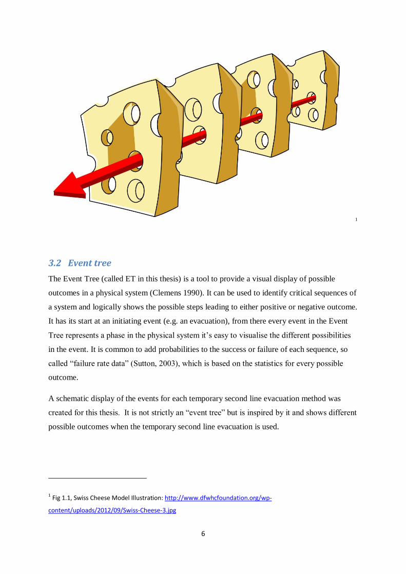
3.1 The Swiss Cheese Model and barrier theory
The Swiss Cheese model is a way of seeing an organizational accident as a breach in several
layers of defenses. Together creating what is called an “accident trajectory”, (Reason 1997 s.
12). A breach in only one defense will not cause an accident but when all defenses are
breached it is likely that an accident soon will happen.
As shown in figure 1.1 , each defense can be seen as a slice of cheese where every hole
represents a flaw in the defense.
Avoiding accidents would be easy if it was this simple, with fully understood, at all times
controlled potential flaws in static barriers, or metaphorically; known holes in lined up slices
of cheese. This is not the case since flaws, or holes, as well as the barriers, are constantly
moving and shifting in size as opposed to being static.
The Swiss Cheese model postulates that a key factor in understanding and preventing
accidents has to do with awareness about when it is likely that a defense may be breached.
There are two types of failures, called active failures and latent conditions, (Reason 1997). An
active failure most often lasts for a short time and has its origin in actions taken by workers
and operators during the execution of an operation. A latent condition, on the other hand,
often has its origin further back in time, arising from the decisions made prior to the operation
taking place and possibly by other people than those involved in the operation, (e.g. the
management, the board of directors). Examples of latent conditions are: poor training, bad
equipment, lacking supervision, cumbersome procedures. A latent condition is often a more

5
serious problem than an active failure in the sense that it is harder to predict its outcome, or
even to know that it is present. Latent conditions may lead to failures and accidents in many
separate parts of the organization thus causing the organization a lot more harm than an active
failure. An active failure often stems from a latent condition, so being aware of possible latent
conditions is a way of decreasing the risk of active failures.
There are two types of defenses, hard and soft, (Reason, 1997). The hard defenses are all the
technical devises in a system that is used to prevent an accident; this could be alarms and
equipment. The soft defenses are everything else; regulations, procedures, training and so on.
Defenses, or barriers, can be further categorized. According to Hollnagel (2004) they can be
separated into the following categories:
Physical Barriers are material hindrances with the function of physically preventing an unwanted
event or action to take place, (e.g. railings, walls, fences).
Functional Barriers are obstructions for an event to happen or an action to be carried out. It is
defenses put in place so that an action cannot be carried out unless one or more pre-conditions are met.
It can be an automated system or require human involvement, (e.g. passwords, locks, airbags).
Symbolic Barriers are defenses which call for a person to voluntarily abide to carry out an action in a
certain way. It requires a person to actively adjust his behavior according to the message that the
barrier carries in order for it to work, (E.g. warning signs, reflective posts along a road).
Incorporeal Barriers are immaterial barriers which carry no physical function. It can be rules for
actions and regulations, attitudes and safety cultures, laws and so on.
6
1
3.2 Event tree
The Event Tree (called ET in this thesis) is a tool to provide a visual display of possible
outcomes in a physical system (Clemens 1990). It can be used to identify critical sequences of
a system and logically shows the possible steps leading to either positive or negative outcome.
It has its start at an initiating event (e.g. an evacuation), from there every event in the Event
Tree represents a phase in the physical system it’s easy to visualise the different possibilities
in the event. It is common to add probabilities to the success or failure of each sequence, so
called “failure rate data” (Sutton, 2003), which is based on the statistics for every possible
outcome.
A schematic display of the events for each temporary second line evacuation method was
created for this thesis. It is not strictly an “event tree” but is inspired by it and shows different
possible outcomes when the temporary second line evacuation is used.
1 Fig 1.1, Swiss Cheese Model Illustration: http://www.dfwhcfoundation.org/wp-
content/uploads/2012/09/Swiss-Cheese-3.jpg

7
4 Method
4.1 Research design
Three methods have been used in order to gather data. When collecting data using different
methods or sources concerning the same subject it is called triangulation (Guion, L, Diehl, D,
McDonald, D). This enhances the validity and accuracy of the data.
Informal discussions and meetings with personnel involved with the project at Aibel AS have
been held; Aibel AS is the company building the platform. A literature study was conducted
were relevant data concerning the project was examined and reviewed. When a framework
had been worked out semi structured interviews were conducted.
The study began with a review of the platform design and premises for the voyage in order to
get an overview of the problem. Relevant documents were available from a database for the
DolWin Beta platform at Aibel AS’s network, these documents are considered confidential
and are not available for the public. In this database there were drawings of the design and
structure of the platform, HAZIDS and HAZOPS, relevant rules and regulations and the Tow
manual to name some. Also the internet has been used as a source of data. The findings from
this review are presented in chapter 5 and 6.
When an overall understanding of the problems regarding the research question had been
established, further work focused on finding and evaluation possible evacuation methods that
would have the fewest obstacles and present the safest escape. Different methods for
temporary second line evacuation were examined, discussed and evaluated between the
authors as well as between the authors and personnel at Aibel AS. Some were dismissed
rather quickly by the authors and/or personnel at Aibel AS as technical issues would make
them impossible to apply on the DolWin Beta platform.
Based on the information collected by employing the above methods interviews were carried
out.
Together with a representative from Aibel AS the authors visited the chute manufacturer
Viking-Life in Bergen, Norway, for further information.
Three evacuation methods (evacuation chute, rappelling and evacuation ladders) were
evaluated in-depth. The data needed for this evaluation was gathered by interviewing people

8
both in regards to technical detail and the human aspect in an evacuation using the suggested
methods.
Relevant data from the interviews will be presented in the findings chapter and will be
referred to as Interview1, Interview2, Interview3, Interview4 and Interview5.
Datasheets from suppliers of relevant evacuation equipment were also examined.
4.1.1 Interviews
Semi structured interviews has been a substantial part of the data collection related to this
thesis. This method was used in order to obtain information from several experts in their
respective field, with the added benefit of enhancing the depth and scope of the data material.
Information from a user perspective as well as the experience of the suppliers could not have
been obtained otherwise.
Two categories of people were interviewed. The first category consists of people directly
involved in the DolWin Beta project - as an employee at the Marine Department at Aibel AS,
a technical manager at Tristein AS and a business developer at AAK AS. From them we have
gathered information about how the temporary second line evacuation can be carried out and
possible problems that might occur with different methods of evacuation.
The second group of interviewees are not affiliated with the project but who have experience
with working on platforms and/or experience with life saving and/or evacuation. They
provided a “user perspective” on whether they would rely on the suggested methods for the
temporary second line evacuation and problems they thought might occur.
Two interviews were conducted with personnel from the company ResQ AS in Bleivik in
Rogaland who work with safety training for ship and offshore personnel. The first interview
was a group interview with two employees, one of whom had 30 years of experience working
on platforms and the other person had 30 years of experience as a sea navigator. Both now
work as safety training instructors for offshore personnel. Because both of them have
extensive experience concerning evacuation- situations and training we wanted to get their
view on how well different methods of second line evacuation would work and what was
needed for them to work (03.04.2013).

9
The second interview with “non-involved” people was with a person that was working with
emergency training for offshore personnel. This interview focused primarily on questions
concerning what preparations needed prior to the tow operation in regards to the temporary
second line evacuation; what the subject imagined that the crew would expect and so forth
(04.04.2013).
The third interview was with an employee of Tristein AS, the company that would be in
charge of the tow of the platform. We wanted to know what responsibility they would have
and what aid they had to offer if an evacuation had to take place. We also wanted to know
what parts of the voyage they considered to be the most dangerous (04.04.2013).
The forth interview was with an employee of Aibel AS who was involved with the DolWin
Beta project. The purpose of this interview was to obtain information on the possibilities and
difficulties of implementing the different suggested temporary second line evacuation
methods for the DolWin Beta (26.04.2013).
The fifth interview was with an employee of AAK AS who has been hired by Aibel AS to
construct a temporary evacuation solution using rappelling for the DolWin Beta platform. The
purpose of the interview was to gain knowledge of how this was to be done and what potential
problems that could occur (29.04.2013).
4.2 Limitations
4.2.1 Literature review
The biggest problem concerning the literature review has been to evaluate the reliability of the
sources. Technical datasheets from manufacturers of evacuation methods and also their
internet web pages has been used in order to present and evaluate the different evacuation
methods and it has not always been possible to verify certain data. An example being the time
stated it would take to perform an evacuation by chute. It was not stated how this information
was obtained, if the time it would take was referring to descent when the chute was already
released or yet had to be, or what conditions that were present.
10
4.2.2 Interviews
A possible weakness in the data collection of this thesis concerning the interviews is that a lot
of technical information about the platform design, the tow operation itself and also a lot of
information about the rappelling evacuation method was gathered from people that were
involved with the DolWin Beta project. There is a possibility that these interview subjects
could have been biased and as a consequence were not fully objective as sources of
information. We do not have any specific evidence to support this in our case however we
assume this as a general rule. When asked about the possible problems in certain parts we got
what seemed to be true and honest answers.
Another problem, concerning the other group of interview subjects who were not involved in
the problem was the sample size and the lack of own experience with a crisis situation on a
platform. The purpose of these interviews was to get a subjective view of what evacuation
method that would be most suitable. It is possible that there could have been limitations to
these subjects knowledge concerning any one method. This means that had the sample size
been bigger, it is possible that the other views than those presented in this thesis would have
been expressed. The reason for not conducting more interviews was limitations in time as well
as the unavailability of suitable subjects to interview.
5 Findings
5.1 Conditions, platform design, POB
The findings from the various methods used will be presented thematically rather than for
each method used.
5.2 Platform design
The DolWin Beta is a submersible floating platform that will be towed to its intended position
where it will be lowered to the bottom (DolWin 2 – Hazid report) (TRI-AIB-HZD-22-2010-
12-01).
The platform has a height of 90 meters, a length of 100 meters and a width of 75 meters (Tow
Manual). The DolWin Beta has three decks at different heights; the weather deck is at the top,
the intermediate deck is the middle and the main deck is the lowest. A helipad located on the

11
weather deck and on the main deck there is a free fall life boat as well as a davit to lower a
mob boat (006026-AI-N-XD-0002-01_04). Helicopter and the two types of lifeboats make up
the permanent first and second line evacuation methods when the platform is in its final
position and is resting on the seafloor (interview4).
The muster station for the DolWin Beta when positioned on the sea bed will be on main deck.
That is where the crew would gather if an evacuation were to happen. According to Aibel AS
data (evacuation routes version 2) the travel time for the crew to the muster station is 8
minutes 33 seconds during the day and 8 minutes 44 seconds at night.
When towed the DolWin Beta will have a draft of 7.8 m in normal weather, this is called
“pontoon draft”. If pontoon draft is not acceptable due to bad weather it is possible to increase
the draft to 15m. This mode is called “survival draft” (Evacuation_Tow_to_field_1_2). At
pontoon draft the distance from weather deck to the sea level is 62 meters and from main deck
to the sea level the distance is 42 meters (DolWin 2 – Hazid report). Consequently the
distance in survival draft is 69 meters from weather deck to the sea level and 49 meters from
main deck to the sea level.
The platform is to be considered “dead” during the tow operation, which means that no
system onboard containing hydrocarbons (e.g. generators) will be active. Therefore there is
little risk of explosion or fire (interview4).
5.3 The Tow
The tow is planned to start in August 2014 from the docks at Aibel AS, Haugesund to
DolWins location in the German North Sea (The German Bight). The tow is planned to take
75.5 hours at a speed of 5.5 knots with 28 personnel onboard (POB) (TRI-AIB-TMA-22-
2010-12-01_Towing Manual, Rev.01). Four of these will be employees of the company AAK
AS. They have been hired by Aibel AS to develop and be in charge of the temporary second
line evacuation method of the DolWin Beta. They are planning to use rappelling as the
temporary second line evacuation method. To use this as the temporary second line
evacuation method for the DolWin Beta was decided during the time this thesis was still being
written and prior to the conclusion was presented. Although the decision was taken the
authors continued to look into different possibilities for a temporary second line of evacuation
as it could have importance to future projects.

12
Aibel AS has hired Tristein AS to carry out the tow and be responsible for the platform and
the safety during the operations. Tristein AS was founded in 2007 and according to their
website they “deliver high standard performance at all levels, based on our vast knowledge
and experience installing offshore wind turbines and floating production units, complex and
heavy lifting, marine management and rig-moves, as well as vessel/rig surveys and quality
surveillance” (www.tristein.no). Tristein AS will supply two vessels for the tow and will
make sure that the vessels are fully certified in accordance with rules, regulations and owner
requirements.
The tow will be divided in three different parts, the inshore tow, the offshore tow and the
installation phase. The inshore tow phase is from the docks in Haugesund to the pilot
disembarkation point. During this phase two additional tugs will be provided by Aibel AS to
help with maneuverability and control. This will take about 13 hours. The offshore tow phase
is approximately 344 nautical miles and will take 62.5 hours. It will take the DolWin Beta
from the pilot disembarkation point directly to the installation site. During this phase the
DolWin Beta will be vulnerable to the weather and other vessels in the area. The DolWin beta
will cross the large shipping route of Skagen the Norwegian trench with depths to 700 meters.
Upon arrival at the DolWin Beta location the tow will rendezvous with 2 installation tugs that
will help with the positioning of the platform while it is lowered to the sea floor.
Tristein AS has appointed a Tow Master for the operation. One of his responsibilities is to
maintain safety during the whole operation after the DolWin Beta has been handed over at
Aibel AS:s quay.
The Marine operation department at Aibel AS has chosen the departure date on the basis of
the stable weather that August usually brings. A meteorological service will be used to
provide meteorological data continuously during the tow. If this data shows that the weather
exceeds the weather limits the Tow Master will steer the platform to shelter.
“The weather criteria for the installation operations are governed by referenced DNV rules
and Offshore Standards, Ref./2/ to Ref./6/” according to the Tow Manual.
.
13
5.4 Rules and regulations
In this chapter the existing rules and regulations concerning the evacuation of a platform such
as the DolWin Beta will be presented. The following are directly quoted from the documents
specified in the headlines.
IMO MSC/Circ.884 GUIDELINES FOR SAFE OCEAN TOWING
Chapter 13, Towed Object.
“13.15 Boarding facilities should be rigged on each side of the towed object.”(s. 9)
Chapter 13, Towed Object.
“13.17 Life-saving appliances in the form of lifejackets and life buoys shall be provided
whenever personnel are likely to be on board the towed object even if only for short periods.
When personnel are expected to remain on board for longer periods of time, liferafts should
also be provided. If the freeboard is more than 4.5 m, liferaft davits should be provided,
unless rendered impractical due to the design or conditions of the towed object.” (s. 9)
Offshore Substations for Wind Farms (DNV OS-J201)
G. Evacuation.
G 100 General
“101 Arrangements shall be made, to the extent necessary, for provisions on the offshore
substation or with suitable persons beyond that will ensure, so far as is reasonably practicable,
the safe evacuation of all persons. Persons shall be taken to a place of safety or to a location
from which they can be recovered and taken to such a place.” (s. 57)
“102 Means of evacuation offer protection from the hazard and have their own motive power
to enable persons to move quickly away from the installation. Such means may include:
davit launched or free fall lifeboat
rescue or transfer vessel (possibly used with winch and crane transfer)
helicopter” (s.57)
14
“103 Arrangements shall be made to ensure, so far as is reasonable practicable, the safe
escape of all persons from the offshore substation in case evacuation arrangements fail. This
may involve entering the sea.” (s.57)
“104 Several locations on the installation should enable persons to escape to the sea. Means
of escape which assist with descent to sea, such as davit launched or throw-over life rafts,
lifebuoys, chute systems, cargo nets or ladders shall be provided.” (s.57)
“105 All offshore substations shall have at least one launchable life raft which can take the
maximum number of persons on the installation. In addition, the following applies:
unmanned installation: When the offshore substation is manned, an emergency
response and rescue vessel (ERRV) shall be in the vicinity of the installation. The
ERRV shall be equipped with fast rescue craft.
manned installation: At least one launchable lifeboat with the capacity of maximum
manning shall be available. Should manning ever exceed the boat’s capacity,
additional provisions shall be made.” (s.57)
H. Rescue and Recovery
H 100 General
“101 Arrangements shall be made to enable persons who have to evacuate an installation to
be recovered or rescued to a place of safety. Such arrangements are:
— facilities and services external to the installation, such as vessels, public sector and
commercially provided search and rescue facilities
— facilities on the installation such as installation based fast rescue or man-overboard craft.”
(s.57)
“102 Arrangements shall be made to rescue persons from the sea or near the installation.
Incidents to be considered shall include a person falling overboard or a helicopter ditching on
landing or take-off.” (s.57)

15
“103 Arrangements for recovery and rescue should take into account:
— the numbers of persons who may need to be rescued or recovered
— the capacity, remoteness and response times of the rescue and recovery services
— potential limitations on availability, daytime, weather conditions and sea states
— the need to cover all stages of the operation
— the nature of work activities being carried out (e.g. over side/under deck work would
require a dedicated rescue craft).” (s.57)
“104 Arrangements shall be regarded as being effective if they secure a good prospect of
persons being recovered, rescued and taken to a place of safety, onshore or offshore, where
medical treatment and other facilities for care are available.” (s.57)
5.5 Non-suitable evacuation methods
Several methods of possible temporary second line evacuation were indentified by
interviewees, and the authors. A number of these methods are not suitable for the DolWin
Beta but are still presented here in order to demonstrate the variety of possibilities that needed
to be examined.
5.5.1 Davit launch able life rafts
A common method of evacuating offshore structures is by life-raft or boat while still on the
vessel and then to lower the raft down to sea level by a davit. In this way the people onboard
don’t have to enter the sea before getting to safety in a life-raft or boat and you can get a
controlled evacuation.
This method was soon dismissed because the wire was to short and the manufacturer
suggested that a longer wire would make the life raft very vulnerable when being lowered
from the main deck where the davits are placed. The distance which it would have to be
lowered is more than 40 meter which could give it a large pendulum motion due to the wind
as there is little sheltering in the platform design. This could render the evacuation
uncontrolled and in worst case fatal. Installing a longer wire would also require a new
certification for the davit.

16
5.5.2 Slide
The slide system is built up on the same way as you can se on all commercial airplanes today.
A slide is released from the vessel down to the sea where a life raft is inflated. All people
onboard the vessel can slide directly down to the life raft. This method is quick and easy, but
there is no product on the market which can be launched from the heights needed for the
DolWin Beta platform (Viking-Life Evacuation Slide, Product Guide).
5.5.3 Freefall lifeboat
A freefall lifeboat is installed on the DolWin Beta which is intended as a second line
evacuation when the platform has been lowered on the installation site. Having this as the
second line evacuation during the tow would not be recommended for several reasons. The
freefall lifeboat installed on the DolWin Beta is certified for a 34 meter drop, when being
towed it will have an altitude that exceeds that.
Another reason is that there is only one freefall lifeboat installed, on one side of the platform;
if the platform would start to tilt to any one side that is not the one where the lifeboat is
placed, it might not be possible to launch it. The problem could be solved by installing one
freefall lifeboat on each side of the platform. This would however require extensive
reconstruction of the platform and would only serve the transit state as having more than one
freefall lifeboat would be redundant when the platform is standing in its final position on the
sea bed. When the platform is in its final position there is little or no risk of it getting list or
lean and therefore little or no risk that the one free fall lifeboat installed would ever fail to
launch.
5.5.4 Chute and rappelling from boat landing platform
Both chute and rappelling from main deck are methods that will be discussed more in depth
later. Initially we thought that these methods could be used and executed from the boat
landing platform, which only has a height of approximately 20 meters above sea level at
pontoon draft. Evacuation from the boat landing platform was discarded for the following
reasons: It would take longer time for the people on board to muster at the boat landing
platform as one has to climb a ladder down to it from main deck, and if someone would be
injured it could prove to be very difficult for that person to climb down the ladder to the boat
17
landing platform. Also, in the event of an emergency it could prove difficult to organize an
evacuation on the boat landing platform because it is not very big (interview4).
In short, the boat landing platform is less suitable to use for these two evacuation methods,
regardless of the lesser height, than the main platform is.
5.6 Chute, rappelling and ladder
In this chapter evacuation methods that have been found to be the most suitable will be
discussed. How they work and what challenges there is in using them will be presented. A
fault tree analysis diagram is presented beneath the text for each evacuation method.
5.6.1 Why these methods?
Having an evacuation chute (www.viking-life.com) as the temporary second line evacuation
method was one of the first methods considered. It is a system that “everybody” knows of and
it is a basic element in safety training for offshore personnel (Interview1).
Using rappelling as a temporary second line evacuation method was considered as it had been
used as an evacuation method during the tow of the Troll A platform (Aibel AS, verbatim).
Both rappelling and the chute were chosen based on the fact that main deck is so high above
the surface of the sea.
Installing ladders down to sea level was discussed by personnel at Aibel AS (interview4) but
dismissed (interview4). The evacuation method was once again suggested and discussed in
interview1 and therefore it was decided that the method would be examined closer.
5.6.2 Evacuation method #1: Evacuation chute
The evacuation chute is a method by which the personnel onboard the platform descends
through a cylindrical tube to reach a boarding platform at sea level where life rafts are
fastened. The chute is located inside a shielding structure on a suitable location on deck and it
is lowered by a winch. It is gravity based meaning one only has to release a break for it to be
lowered. Once the chute reaches the sea level a boarding platform is inflated. Life rafts are
connected to the boarding platform. Inside the “tube” there are slides running at an opposing
18
angle in a zig zag pattern so a person descending it does so in a controlled manner (Viking-
Life product guide, Chute).
5.6.3 Review of the Chute
The release mechanism of this construction is simple and there is very little chance of it
failing (Viking-Life product guide). Though releasing the chute is simple, it might not
successfully land in the water if the platform is subjected to list or lean and if it lands in the
water it could still become non-functioning if the platforms list or lean is increased later on
(interview1). The platform needs to be standing more or less still for a chute to work since
velocity of the platform will make the chute drag in the water (Interview1).
When the chute has reached the sea level two persons will descend the chute in order to
inflate and prepare the life rafts connected to the platform at the lower end of the chute. If
these two persons successfully manages to descend the chute and reach the platform at sea
level it is unlikely that they would fail to inflate the life rafts, given they are familiar with how
it is done (Verbatim, Viking-Life personnel). There are 4 life rafts connected to the platform
which means there is redundancy if one of the life rafts were to malfunction. It is however
unlikely that any one of them would (Verbatim, Viking-Life personnel). The next step is for
the rest of the crew to descend the chute. If no one is injured and everyone performs the
descent as intended the chute has the capacity to get 140 persons down in 10 minutes
according to a producer of life saving equipment (Viking-Life product guide). Interviews
estimated the time for an evacuation using a chute, from that the alarm is raised to when all
persons has made the descent to be approximately 25-30 minutes (Interview1).
It is unlikely that someone gets stuck in the chute, but if it would happen, people above him
can climb past him the on the outside and re-enter under him, as the chute has openings in
every cell (Interview1).
The chute is not suited for people who are injured. If a person has broken a bone or is in an
unconscious state it is very hard to get that person down the chute (Interview1).
There are chutes that could be used on the DolWin Beta platform (Viking-Life product guide).
A good placement of the chute would be on the backside of the platform, considering the front
as the direction which the platform will be towed in. The reason being that the life rafts
connected to the chute’s platform would have the biggest chance of drifting away from the
19
DolWin Beta from here. Another possibility could be to have two chutes installed; one in the
right or left front corner and one diagonally on the back (Interview1). Having a chute installed
in the front would not be wise since the towlines are connected in the front and also it is less
likely that the life rafts would drift away from the platform than it is on any other side of the
platform. This is because the platform is most likely moving in the direction it is towed
(interview4).
It is not possible to install a chute on the DolWin Beta without making considerable
reconstructions. An installation platform would have to be built on the side of the DolWin
Beta so that the chute would gain free access vertically to the sea (Interview4). Possible
locations to make reconstructions and install a chute on the platform are in the front on
intermediate deck or on main deck on any of the other sides. Because the evacuation
equipment would only be used in the towing phase it would have to be removed once the
platform was standing on the sea floor. The crane on the DolWin Beta would not be able to
reach an installed chute on the aft side of the platform, which would be the best place to
install it. It would however be able to reach the other three sides (interview4).

20
5.6.4 Event Tree for evacuation by chute
(1)Successful launch of chute on
preferred site
(2.1)Two persons descend the chute
YES
(3)Successful inflation of life rafts
(4)All personnel succesfully descends
(5)Successful release of life rafts
YES
YES
YES
(2.2)Successful launch of chute on
other site
NO
(2.3)Move to safest location on the
platformNO
YES
(3.1)All personnel descends and jumps
into the seaNo
(6)Move away from platform and wait
for pickup
YES
NO
NO
NO

21
5.6.5 Evacuation method #2: Rappelling
Rappelling is a rope based system used for descending from heights that are not safe for a
normal descent. Rappelling was invented in Chamonix in the 1870s by a climber called Jean
Charlet-Straton (Roger Frison-Rocheand and Sylvain Jouty, 1996). Then and now it is as a
way for climbers to get climbers down from mountains. The same technique is used by
climbers today and is proved to be a safe and reliable system.
Today rappelling is used in a lot of different industries where you are working at height.
Every industry has adapted the concept of rappelling in different ways to suit their needs in
their work areas. The military uses one way to get down from helicopters and a window
washer on skyscrapers uses another.
5.6.6 Review of Rappelling
The system is based of different components, the rope, an anchor, pullies, a harness and a
brake. This configuration can be set up in different ways so that either the descendant has the
control over the descent or if it’s controlled by a second person standing underneath or above.
On a single person system the rope is fixed on an anchoring point above the descendent. The
rope then goes thru a brake on the persons harness which uses friction to slow down and stop
the descendant on his way. The brake system can work in different ways, a climber can use a
special knot that he fixes to the harness, by applying more or less force to the brake he
controls his speed down the mountain. Another braking system is the automatic brake system
where the descendant has to squeeze a leaver to release the brake and descend. If he lets go of
the handle the brake closes and he stops.
In a two men rappelling system the rope is fixed on the descendants harness, it then goes up to
the anchor point and down to the second person who controls the brake. To imagine this
system you can think about a water well where you have the bucket on a rope and you are
standing above controlling the leaver.
The company AAK AS will have four different rappelling zones, one on each side of the
DolWin Beta. Because the platform during an accident can lean and list in any direction and
choosing the safest rappelling zone will be critically. Groups up to four persons will be
lowered together down to sea level. The descent will be controlled by personnel from AAK
AS on top of the platform. It will also be possible using this system to transport a person with

22
injuries with a stretcher. When all personnel from the DolWin Beta have been lowered down
to sea level the personnel from AAK AS will use a single person system and descend on their
own.
When the personnel reach the surface they will unhook from the rope and swim away from
the platform to a nearby MOB boat from Tristein according to AAK AS (Interview 5). It is
important during this phase to have good communication between the personnel from AAK
AS and Tristein AS so that everyone that where lowered is accounted for. How this
communication will be established is not yet decided by AAK AS (interview 5). The MOB
boat will go back and fourth between the rappelling zone and one of the tug boats.
All the personnel during the evacuation will be protected by a rescue suit. These suites are
standard on all larger vessels operation on the North sea and they are fitted with lights,
designed to be buoyant as well keeping the person warm and dry (interview 1).
23
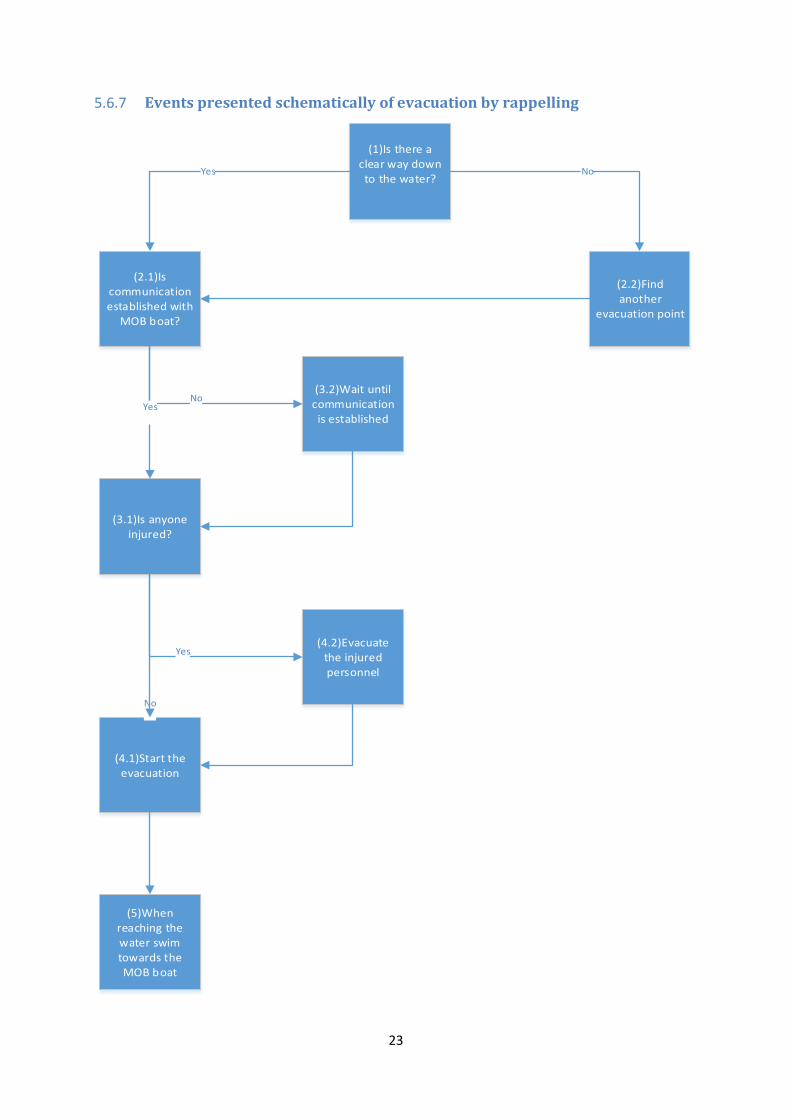
5.6.7 Events presented schematically of evacuation by rappelling
(1)Is there a clear way down to the water?
(2.1)Is communication established with
MOB boat?
Yes
(2.2)Find another
evacuation point
No
(3.1)Is anyone injured?
(4.2)Evacuate the injured personnel
(3.2)Wait until communication is established
NoYes
Yes
(4.1)Start the evacuation
No
(5)When reaching the water swim towards the MOB boat

24
5.6.8 Evacuation method #3: Ladder to the pontoons
Offshore installations often have ladders constructed that go all the way down to sea level
(interview1). Ladders that are mounted vertically to the structure so that personnel are able to
climb down from the platform and step right into the sea. On the DolWin Beta an existing
ladder can take the personnel down to the boat landing platform but not all the way down to
sea level. If a ladder would be installed for the remaining descent it would have a safety cage
surrounding the person and a vertical lifeline (interview4) which in turn is connected to a rope
grab deceleration device which locks in the event of a fall (http://www.fallprotect.com).
5.6.9 Review of evacuation ladder
The ladder evacuation method is very simple in its design and it has been suggested that
people would feel comfortable using it (interveiw1). It could be used as a backup (interview1)
so if both the first and secondary evacuation method would fail there would be a way to
manually descend to the sea level. Interview subjects would rather use this method than
rappelling in the event of an evacuation (interview1).
The surrounding cage and the rope grab system can protect a person who would fall. There
are different types and patents of rope grabs (http://www.fallprotectionpros.com). A rope grab
system is designed so that it is possible for a person to move up and down vertically along a
lifeline and in the event of a fall the rope grab will tighten around the lifeline and decelerate
and stop the fall (www.fallprotectionpros.com) (www.fallprotect.com).
It is not certain where one would have to exit the ladder to get into the water in the event of an
evacuation because the platform could be sinking, thus making the water line relatively higher
to the platform. As a cage will be surrounding the ladder a solution of how to get exit points
would have to be worked out so that the personnel descending the ladder won’t be trapped
inside it (interview4).
A ladder from main deck down to the boat landing platform already exist on the DolWin Beta
so all that is needed in order to have a ladder to the sea is an extension of the existing ladder
the last 28. It would also be possible to install additional ladders at different locations on the
platform (interview4).
It could however prove to be a difficult task to remove the ladder once the platform is seated
on the sea bed. The ladder would at that point be under water (interview4).

25
5.6.10 Events presented schematically of evacuation by ladder
(1)Is it possible to descend the ladder?
(2.1)The rope grab system works
(3.1)Descend the ladder
(4)Everyone successfully decends the ladder
YES
YES
(2.2)It is possible to descend at another ladder at another location
(3.2) It is possible to descend safely without the rope grab system
NO
YES
YES
NO
(3.3)Move to safest location on the platform
NO
YES
NO
NO
(5)Jump into the sea and wait for pickup

26
6 Discussion
Advantages and disadvantages of using the chute, rappelling and the ladder as the temporary
second line evacuation method on the DolWin Beta are presented in the discussion. The
methods have then been compared to each other. The Swiss Cheese model (Reason 1997), the
barrier categorization by Hollnagel (2004) and the “Event Tree” (Clemens 1990) has been
used as a help to identify weaknesses and strengths of the evacuation methods.
6.1 Advantages of the chute
The chute is a well known evacuation method and that is in itself a huge strength. If people
are familiar with an evacuation method they feel safer using it. People tend to do what they
have been drilled to do when an evacuation is about to take place and therefore one can expect
a controlled evacuation if the chute were to be used. The chute may also give a sense of
security as it envelopes the person and offers a clear route down to the sea level. When using
the chute all personnel will stick together and there is never a situation where someone is on
their own. Communication between the crew will therefore be a relatively easy task. The fact
that it is a well know systems that people are familiar to use makes a strong incorporeal
barrier according to Hollnagel (2004) against active failures and would probably have a
positive effect when it comes to how willing people would be to descend the chute (see
phase4 in the event tree). The communication aspect makes active failures according to the
Swiss Cheese model less likely to occur.
Because the chute is a well know evacuation method which is included in basic offshore
training there would be no need for the crew to undergo extensive preparations or training in
how to operate it. The system is very easy to use; releasing a break and waiting for the chute
to reach sea level. If this is done successfully and two people manages to descend the chute
and inflate the life rafts it will only take minutes for the rest of the personnel to descend it.
The descent in itself is an easy task to perform for anyone who is not injured. These are
physical as well as incorporeal barriers according to Hollnagel (2004) as it concerns the
technical design of the evacuation method as well as it require organisational training of the
personnel. These barriers positively affect the outcome of phase 1, 2.1, 3, 4 and 5 of the ET
and makes active failures less likely to occur according to the Swiss Cheese model.

27
Another advantage to the chute method of evacuation is that life rafts are connected to it at sea
level. As soon as a person has descended the chute he or she can immediately transfer to a life
raft and therefore never has to enter the water. This is likely to give a sense of security to the
personnel onboard, as they will not have to enter the water. This makes a strong physical
barrier according to Hollnagel (2004) as it is a technical solution created in order to increase
the safety of the personnel. This affects phase 4 and 6 of the ET.
6.2 Disadvantages of the chute
If any personnel would be injured with a broken bone or if anyone would be unconscious it
could prove to be very hard to get that person down the chute. According to the Swiss Cheese
Model this is a latent condition. It effects phase 4 of the ET and as seen in the ET there is no
way to get an injured person down to sea level by using the chute if it were to happen.
An active failure that could penetrate any defense of an evacuation by chute has its cause in
the height of the platform. If any personnel would become afraid of the height, it could prove
difficult to make this person perform the descent through the chute, regardless of his physical
condition.
The chute can only be used if the platform is standing more or less still in the water because
otherwise the chute would drag in the water making it impossible to use. This also means that
heavy currents or waves could become a problem. This is a significant problem as the weather
in a situation where an evacuation is needed is likely to be bad. Also, if the platform would be
subjected to heavy list or lean it would not be possible to use the chute. This too is a latent
condition according to the Swiss Cheese model and there is lacking a physical and/or
incorporeal barrier (Hollnagel, 2004). It affects phase 1 of the ET, which is the most critical
phase because if this phase fails there is no way for the personnel to get down to sea level.
Using a chute as the temporary second line evacuation of the DolWin Beta is troublesome
because there are few suitable locations to place the chute. The best location would be in the
middle of the aft because the life rafts would have the best chance of drifting away from the
platform once released from the chute’s platform. This is however not possible due to the
design of the DolWin Beta. The second best solution is to have two of them, one on each side
of the platform.

28
6.3 Advantages of rappelling
Personnel dedicated to be in charge of a potential temporary second line evacuation by
rappelling will be present during the tow. This makes active failures less likely to occur and
one can assume that it will have a calming effect of the rest of the personnel.
The personnel in charge will serve as physical-, functional-, symbolic- and incorporeal
barriers (Hollnagel, 2004), at the same time and it affects every phase of the evacuation as
seen in the ET. They are an incorporeal barrier (Hollnagel, 2004), in the sense that the rules of
action in the event of an evacuation will be very clear. They are physical barrier (Hollnagel,
2004) as they will work to physically prevent unwanted actions to be carried out or events to
happen. They also serve as functional barriers; an example being that they will prevent a
person to begin descending the rope before that person is properly connected. They serve as
symbolic barriers (Hollnagel, 2004) as they will carry out orders and share information with
the rest of the personnel and in the end the outcome of the evacuation is highly dependent on
that everyone abides these instructions. This shows that barriers (Hollnagel, 2004) can be
combined in order to create a safe as possible environment.
Technically the system doesn’t contain any difficult parts and very little can malfunction
according to AAK AS (interview 5); it’s basically a rope, a harness and a brake.
When adapting the system to the DolWin Beta you easily see the flexibility of the system.
There are different evacuation points that don’t take up a lot of space and it is easy to switch
from one evacuation point to another (see phase 1 and 2.2 in ET). You can set up the system
on the side of the platform that has the lowest height over the water in case of list and/or lean.
The evacuation points will be prepared a head of time on the different sides so no equipment
has to be moved (interview 5). Since the rules of action will be very clear in any platform
condition it serves as an incorporeal barrier.
Another advantage is that is the only system that can handle a person with injuries. It is
possible to lower a stretcher with one person and have another person attached on the side.

29
6.4 Disadvantages of rappelling
An active failure that could penetrate any defense of an evacuation by rappelling has its cause
in the height of the platform. If any personnel would become afraid of the height, it could
prove difficult to make this person perform the descent; although the fact that there are
experienced personnel present who is in charge is a barrier which hopefully counters this.
Having satisfying communication between the people that are being lowered and the
personnel from AAK AS and between the MOB boat and AAK AS is an important aspect of
the evacuation (interview 5). If this is not worked out it would be a latent condition that could
jeopardise the safety of the personnel onboard the DolWin Beta.
It is planned to rappel the personnel into the sea in groups between 2-4 people. When reaching
the surface of the sea the personnel will then unhook themselves from the vertical life line and
be picked up by a MOB boat from Tristein AS (interview 5). This could be dangerous because
of potential platform movement and possible wind and wave factors. According to AAK AS
this is the most critical point of the evacuation and it’s not decided exactly how it will be
solved.
If there are strong winds and the ocean is carrying heavy waves there is a possibility that it
would not be possible to launch a MOB boat from the tugboats. There is no weather limit for
launching the boats but it is up to the captain on each vessel to decide if the launch can be
done in a safe way (interview 3). If the MOB boats can’t be mobilized and launched due to
the weather there will be no way of transporting the personnel of the DolWin Beta from the
water to safety.
Also the fact that the personnel on the DolWin Beta would have to descend into the sea rather
than into a life raft is a disadvantage with using rappelling as an evacuation method. This adds
a new danger in the middle of the evacuation which is not the purpose. Water presents a new
danger to the situation as the person still need to be picked up by a MOB boat in order to
reach safety and this can not be controlled by AAK AS. An evacuation is designed to start at a
potentially dangerous situation and gradually take the personnel to a safer environment.
Although there seem to be little risk of active failures when using rappelling as an evacuation
according to the Swiss Cheese model, there are obviously few barriers against unwanted
events to happen in the last phase of the evacuation (see phase 5 of the ET).
30
6.5 Advantages of the evacuation ladder
The ladder evacuation method is very simple in its design and people would likely feel at ease
using it as a method of evacuation. The cage surrounding the ladder as well as having a rope
grabbing system connected to a vertical life line makes the system safe when descending as
there is little risk of falling. The cage is a physical barrier (Hollnagel, 2004), and the rope
grabbing system is a functional barrier (Hollnagel, 2004), as it intervenes when a certain pre-
condition is met, i.e. when a person is falling.
Because of the simplicity of the ladder method there is little that could fail technically and an
evacuation is executed in a few steps (see ET). If ladders were to be mounted on several
locations of the platform it would enable descent in most platform conditions in regard to list
and lean.
There is little risk of active failures when using this method of evacuation.
6.6 Disadvantages of the evacuation ladder
The descent from main deck to the sea could be physically challenging for the personnel,
especially when wearing a life suit. If the platform were to lean to any side it could be hard to
make the descent regardless if there were ladders mounted in different locations on the
platform. It could also prove to be very hard to evacuate an injured person by using a ladder.
If no solution is prepared for this it is a latent condition according to the Swiss Cheese model.
A potentially dangerous situation that could occur is if the ladder would have a safety cage
surrounding it is that a person might not be able to exit if the platform were to sink and the
water level got above where the cage’s bottom exit is. This could be seen as a latent condition
according to the Swiss Cheese model. The cage is initially a physical barrier with the purpose
of hindering a person to fall of the ladder but in certain conditions, as the one described
above, it could become a death trap.

31
6.7 Comparison of the evacuation methods
Following is a comparison between the temporary second line evacuation methods where the
most important factors for a successful and safe evacuation will be discussed.
6.7.1 Which method makes people feel the safest?
If an evacuation was to take place it is of great importance that the people on the platform
would feel safe using it. If the platform would have no or little list or lean a stairway down to
sea level would probably be the best method of evacuation in this aspect. At the same time a
chute would be to prefer over rappelling due to the recognition that the chute has in the
offshore environment compared to rappelling. The chute also gives a person a sense of safety
because of its design where one is descending in a firm structure. It is likely that rappelling
would be frightening to some but on the other hand it has an advantage over both the ladder
and the chute because if it were to be used, people dedicated to lead the evacuation would
have to be present on the platform. Having personnel onboard whose only task is to execute
and lead an evacuation would likely have a positive impact on how safe people would feel if
an evacuation was to take place.
6.7.2 Simplicity and safety
Technically, a stairway down to the water level is by far the easiest system to use of the three.
Stairways would be mounted to the platform and little preparation would be needed before
personnel could start to descend one of them. There is not much that could malfunction with a
stairway. A chute is easy to launch as it is only a break that needs to be lifted. Going down a
chute is an easy task. However, if anything would malfunction on the chute and it would fail
to launch properly there is very little personnel onboard could do to fix the problem. Under
normal circumstances it is unlikely that the chute would fail to deploy but weather or platform
conditions like list or lean or velocity could make it not work. Rappelling is a more versatile
evacuation method then the chute because it can be used regardless of list or lean and because
there are more possible sites from where it could be launched. Since dedicated personnel will
be in charge of lowering all people to the sea level the method is to be considered technically
simple to use. The personnel hired to be in charge of the evacuation also serves as barriers
against technical problems with the rappelling method.
32
The chute has an advantage over both the rappelling- and ladder method when it come to the
part of the evacuation where the people on board have managed to descend the platform and
reach sea level. The chute has life rafts connected to the landing platform at sea level so there
is no need to ever go directly into the water. It is not certain that this would be the case if
using either the rappelling method or the stairway method and the personnel might have to go
into the sea. However if it would be arranged so that the personnel could either rappel straight
into life rafts or step into life rafts when using evacuation ladders the three methods would
have to be considered equally good in this aspect.
6.7.3 Handling injured people
If any personnel would be injured it would be very hard to get them down to the sea level by a
stairway or chute. In this aspect rappelling come out on top as it is possible to rappel a person
on a stretcher or to rappel a person with a fractured limb.
6.7.4 Physical layout of the DolWin Beta
When it comes to installing the evacuation methods on the platform both ladders and
rappelling has an advantage over the chute as the placement of the chutes are restricted to the
starboard and port side of the platform. Also the chute requires a more extensive construction
to be built before it could be installed than the other two methods.
33
7 Conclusion
The three evacuation methods, chute, rappelling and ladder, all have strong sides. When
compared against each other it is clear that the chute is the most recognizable system,
rappelling is the only system that can handle injured and the ladder would be the easiest to
use. So based on the strong sides all of them could be used as a secondary evacuation method
for the DolWin Beta but every solution comes with its own disadvantages and it is the system
with the least disadvantages that will be the most suitable.
Based on the discussion and the available data we conclude that the best evacuation method
for the DolWin Beta would be rappelling due to the fact that it is the only system that can
handle injured, it is flexible and not easily affected for list/lean and AAK AS will provide
with personnel that will be responsible for the evacuation.
The problem remains to how the personnel that has reached the water will be brought to
safety; this is the most critical point in the evacuation. A solution has to be found before the
tow of the DolWin Beta begins.
The ladder and the chute are both good systems and could be recommended systems for other
projects but for the DolWin Beta they are not optimal.

I
8 References
006026-AI-N-XD-0002-01_04, (confidential).
G:\006026_DolWin\Engineering\Structural\Tegninger\til DCC FOR IDC\2012\til DCC FOR
IFC 20.09.2012
AAK AS, www.aak.no accessed 06.05.13
Aibel AS, http://aibel.com/en/projects/the-dolwin-2-wind-platform, accessed 06.05.13
Australian Transport Safety Bureau, (1984), Loss of tow and subsequent foundering off the
coast of western Australia on 1st September 1983
http://www.atsb.gov.au/publications/investigation_reports/1984/mair/pdf/mair3_001.pdf,
accessed 02.05.13
Clemens, P, (1990), Event tree analysis, http://www.fault-tree.net/papers/clemens-event-
tree.pdf, accessed 10.05.13
Diversified Fall Protection LLC
http://www.fallprotect.com/fall-protection-solutions/vertical-lifelines-and-ladder-systems/,
accessed 02.05.13
DNV, (2009), Offshore Substations for Wind farms (OS-J201)
https://www.google.no/url?sa=t&rct=j&q=&esrc=s&source=web&cd=1&ved=0CCwQFjAA
&url=http%3A%2F%2Fexchange.dnv.com%2Fpublishing%2Fcodes%2Fdownload.asp%3Fur
l%3D2009-10%2Fos-j201.pdf&ei=0uCHUZ-
GEYLvswbz2oCwCA&usg=AFQjCNHdJJR7B6dXNsHRH9-
Rp8iRN4ZZlw&sig2=uqV7giA_z4oGBUi5eacZ6g&bvm=bv.45960087,d.Yms, accessed
10.05.13

II
Evacuation routes version 2, (confidential)
(G:\006026_DolWin\Engineering\Safety\Bachelor - Sikkerhet i midlertidige
faser\JAB\Evacuation)
Fall Protection Pros.com
http://www.fallprotectionpros.com/blog/how-to/how-rope-grabs-work/ , accessed 03.05.13
Flin, R, Mearns, K, O’Conner, P, Bryden, R, (2000) Measuring safety Climate: Identifying
the common features Safety Science, Aberdeen: University of Aberdeen, King's College
http://www.abdn.ac.uk/iprc/documents/Measuring%20Safety%20Climate...%20FLIN.MEAR
NS.OCONNOR%20220205.pdf, accessed 10.05.13
Frison-Rocheand, R, Jouty, S, (1996) A History of Mountain Climbing, Paris: Flammarion
Guion, L, Diehl, D, McDonald, D. (2011), Triangulation: Establishing the Validity of
Qualitative Studies, Florida: University of Florida
Hollnagel, E, (2004), Barriers and accident prevention, Aldershot: Ashgate
Kvitrud, A, Kulander Kvitrud, E, (2012) Vekting av hendelser på konstruksjoner og maritime
systemer (DFU 8) i RNN. Petroleumstilsynet
http://www.ptil.no/getfile.php/PDF/RNNP%202011/2011%20revidert%20rapport%20Vektin
g%20av%20hendelser%20p%C3%A5%20konstruksjoner%20og%20maritime%20systemer%
20i%20RNNP.pdf, accessed 10.05.13
Reason, J, (1997) Managing the Risks of Organizational Accidents, Aldershot: Ashgate
Steensen, A, (1999), Teknisk Ukeblad 20. okt 1999,
http://www.tu.no/nyeteknologier/1999/10/20/arhundrets-ingeniorbragd-1900-2000-
trollbinder-hele-verden, accessed 10.05.13
Sutton, I, (2003), Fault tree analysis, Houston: Sutton Technical Books
Tellnes, I, (2008), Lasteberegninger og behandling av last, Oslo: Universitetsforlaget
III
Tow Manual DolWin Beta, (confidential).
TRI-AIB-TMA-22-2010-12-01_Towing Manual, Rev.01
Tristein AS, http://www.tristein.no/article.aspx?id=745, accessed 06.05.13
Tylor, P, (1995) The shape of the Draupner Wave of 1 st January 1995. University of Oxford
http://www.icms.org.uk/archive/meetings/2005/roguewaves/presentations/Taylor.pdf,
accessed 10.05.13
United States Coast Guard, (1978), Report No USCG 16732 / 61865
http://www.uscg.mil/hq/cg5/cg545/docs/boards/oceanex.pdf, accessed 10.05.13
Viking-life Chute
http://www.viking-life.com/usr/viking/TradeingItems.nsf/lookupcertusers/Datasheet122-
60:SES-2B/$FILE/SES%202B_Feb07_print%20ready.pdf, accessed 06.05.13
Viking-life Slide
http://www.viking-
life.com/usr/viking/TradeingItems.nsf/lookupcertusers/DatasheetVES%20Slide-
Guide/$FILE/05666586.pdf, accessed 06.05.13
West Gamma, (1990), Oil Rig Disasters, http://www.oilrigdisasters.co.uk/, accessed 10.05.13