ericdevos.be files/panasonic eva1.pdf · 2019-09-21 · read this first! – 3 – indicates safety...
TRANSCRIPT

Operating InstructionsMemory Card Camera-Recorder
Before using this product, be sure to read “Read this first!” (pages 2 to 6).Before operating this product, please read the instructions carefully and save this manual for future use.
ENGLISHDVQP1561UA
W1017HM5019 -YI
Model No. AU-EVA1
P PJ EN ED AN PX

Read this first!
– 2 –
Read this first! indicates safety information.
CAUTIONRISK OF ELECTRIC SHOCK
DO NOT OPEN
CAUTION: TO REDUCE THE RISK OF ELECTRIC SHOCK, DO NOT REMOVE COVER (OR BACK).
NO USER-SERVICEABLE PARTS INSIDE.REFER TO SERVICING TO QUALIFIED SERVICE PERSONNEL.
The lightning flash with arrowhead symbol, within an equilateral triangle, is intended to alert the user to the presence of uninsulated “dangerous voltage” within the product’s enclosure that may be of sufficient magnitude to constitute a risk of electric shock to persons.The exclamation point within an equilateral triangle is intended to alert the user to the presence of important operating and maintenance (servicing) instructions in the literature accompanying the appliance.
WARNING:• To reduce the risk of fire or electric shock, do not
expose this equipment to rain or moisture.• To reduce the risk of fire or electric shock, keep
this equipment away from all liquids. Use and store only in locations which are not exposed to the risk of dripping or splashing liquids, and do not place any liquid containers on top of the equipment.
WARNING:Always keep memory cards (optional accessory) or accessories (microphone holder screws) out of the reach of babies and small children.
CAUTION:To reduce the risk of fire or electric shock and annoying interference, use the recommended accessories only.
CAUTION:The mains plug of the power supply cord shall remain readily operable.The AC receptacle (mains socket outlet) shall be installed near the equipment and shall be easily accessible.To completely disconnect this equipment from the AC mains, disconnect the power cord plug from the AC receptacle.
CAUTION:Danger of explosion or fire if battery is incorrectly replaced or mistreated.• Do not disassemble the battery or dispose of it
in fire.• Do not store in temperatures over 60°C (140°F).• Do not expose the battery to excessive heat
such as sunshine, fire or the like.For Battery Pack• Use specified charger.• Replace only with same or specified type.
CAUTION:In order to maintain adequate ventilation, do not install or place this unit in a bookcase, built-in cabinet or any other confined space. To prevent risk of electric shock or fire hazard due to overheating, ensure that curtains and any other materials do not obstruct the ventilation.
CAUTION:Do not lift the unit by its handle while the tripod is attached. When the tripod is attached, its weight will also affect the unit’s handle, possibly causing the handle to break and hurting the user. To carry the unit while the tripod is attached, take hold of the tripod.
CAUTION:Excessive sound pressure from earphones and headphones can cause hearing loss.
CAUTION:Do not leave the unit in direct contact with the skin for long periods of time when in use.Low temperature burn injuries may be suffered if the high temperature parts of this unit are in direct contact with the skin for long periods of time.When using the equipment for long periods of time, make use of the tripod.
CAUTION:Keep metal objects (such as necklaces and hairpins) away from the battery.Short-circuiting may occur across the terminals, causing the battery to heat up, and you may seriously burn yourself if you touch the battery in this state.

Read this first!
– 3 –
indicates safety information.
CAUTION:This apparatus can be operated at a voltage in the range of 100-240 V AC.Voltages other than 120 V are not intended for U.S.A. and Canada.Operation at a voltage other than 120 V AC may require the use of a different AC plug. Please contact either a local or foreign Panasonic authorized service center for assistance in selecting an alternate AC plug.
FCC NOTICE (USA)CAUTION:This equipment has been tested and found to comply with the limits for a Class B digital device, pursuant to Part 15 of the FCC Rules. These limits are designed to provide reasonable protection against harmful interference in a residential installation. This equipment generates, uses and can radiate radio frequency energy and, if not installed and used in accordance with the instructions, may cause harmful interference to radio communications. However, there is no guarantee that interference will not occur in a particular installation. If this equipment does cause harmful interference to radio or television reception, which can be determined by turning the equipment off and on, the user is encouraged to try to correct the interference by one or more of the following measures:• Reorient or relocate the receiving antenna.• Increase the separation between the equipment and receiver.• Connect the equipment into an outlet on a circuit different from that to which the receiver is connected.• Consult the dealer or an experienced radio/TV technician for help.The user may find the booklet “Something About Interference”available from FCC local regional offices helpful.
FCC Warning:To assure continued FCC emission limit compliance, follow the attached installation instructions and the user must use only shielded interface cables when connecting to host computer or peripheral devices. Also, any unauthorized changes or modifications to this equipment could void the user’s authority to operate this device.

Read this first!
– 4 –
indicates safety information.
NOTIFICATION (Canada)CAN ICES-3(B)/NMB-3(B)
The rating plate is on the underside of the Camera Recorder, Battery Charger and AC Adaptor.
IMPORTANT SAFETY INSTRUCTIONS1) Read these instructions.2) Keep these instructions.3) Heed all warnings.4) Follow all instructions.5) Do not use this apparatus near water.6) Clean only with dry cloth.7) Do not block any ventilation openings. Install in accordance with the manufacturer’s instructions.8) Do not install near any heat sources such as radiators, heat registers, stoves, or other apparatus (including amplifiers) that
produce heat.9) Do not defeat the safety purpose of the polarized or grounding-type plug. A polarized plug has two blades with one wider
than the other. A grounding-type plug has two blades and a third grounding prong. The wide blade or the third prong are provided for your safety. If the provided plug does not fit into your outlet, consult an electrician for replacement of the obsolete outlet.
10) Protect the power cord from being walked on or pinched particularly at plugs, convenience receptacles, and the point where they exit from the apparatus.
11) Only use attachments/accessories specified by the manufacturer.12) Use only with the cart, stand, tripod, bracket, or table specified by the manufacturer, or sold with the apparatus.
When a cart is used, use caution when moving the cart/ apparatus combination to avoid injury from tip-over.13) Unplug this apparatus during lightning storms or when unused for long periods of time.14) Refer all servicing to qualified service personnel. Servicing is required when the apparatus has been damaged
in any way, such as power-supply cord or plug is damaged, liquid has been spilled or objects have fallen into the apparatus, the apparatus has been exposed to rain or moisture, does not operate normally, or has been dropped.
For USA and CanadaA lithium ion/polymer battery that is recyclable powers the product you have purchased.Please call 1-800-8-BATTERY for information on how to recycle this battery.

Read this first!
– 5 –
Brazil Only Brasil Apenas
r Manuseio de baterias usadasBRASILApós o uso, as pilhas e /ou baterias poderão ser entregues ao estabelecimento comercial ou rede de assistência técnica autorizada.
Cobrir os terminais positivo (+) e negativo (-) com uma fita isolante adesiva, antes de depositar numa caixa destinada para o recolhimento. O contato entre partes metálicas pode causar vazamentos, gerar calor, romper a blindagem e produzir fogo.Não desmonte, não remova o invólucro, nem amasse a bateria. O gás liberado pela bateria pode irritar a garganta, danificar o lacre do invólucro ou o vazamento provocar calor, ruptura da blindagem e produzir fogo devido ao curto circuito dos terminais. Não incinere nem aqueça as baterias, elas não podem ficar expostas a temperaturas superiores a 100°C (212°F). O gás liberado pela bateria pode irritar a garganta, danificar o lacre do invólucro ou o vazamento provocar calor, ruptura da blindagem e produzir fogo devido ao curto circuito dos terminais provocado internamente.Evite o contato com o liquido que vazar das baterias. Caso isto ocorra, lave bem a parte afetada com bastante água. Caso haja irritação, consulte um médico.
To remove the batteryPara remover a bateria
Main Power Battery (Lithium ion Battery)Bateria Principal de Energia(Refer to page 33 for the detail.)Press the battery release button.Pressione o botão para liberar a bateria.
Battery release buttonBotão de liberação da bateria
Back-up Battery (Lithium Battery)• For the removal of the battery for disposal at the end of its service life, please consult your dealer.

Read this first!
– 6 –
r Batteries that may be used with this product (as of October 2017) Panasonic AG-VBR59 / AG-VBR89 / AG-VBR118 / VW-VBD58 batteries may be used with this product.
It has been found that counterfeit battery packs which look very similar to the genuine product are made available to purchase in some markets. Some of these battery packs are not adequately protected with internal protection to meet the requirements of appropriate safety standards. There is a possibility that these battery packs may lead to fire or explosion. Please be advised that we are not liable for any accident or failure occurring as a result of use of a counterfeit battery pack. To ensure that safe products are used we would recommend that a genuine Panasonic battery pack is used.
Battery Charger / AC AdaptorDisconnect the AC mains plug from the AC mains socket when not in use.
r The symbols on this product (including the accessories) represent the following:
d AC
e DC
Class II equipment (The construction of the product is double-insulated.)

– 7 –
CopyrightThe clips that you have shot (recorded, etc.) cannot be used without permission of the right holder under the copyright law unless of a personal use. Note that the shooting may be restricted even if it is for personal use.
Trademark fSDXC logo is a trademark of SD-3C, LLC. fAVCHD, AVCHD Progressive, and AVCHD Progressive logo are trademarks of Panasonic Corporation and Sony Corporation. f This is manufactured based on license from Dolby Laboratories, Inc. Dolby, Dolby Audio, and the double-D symbol are trademarks of Dolby Laboratories. f The terms HDMI and HDMI High-Definition Multimedia Interface, and the HDMI Logo are trademarks or registered trademarks of HDMI Licensing Administrator, Inc. in the United States and other countries. fMicrosoft® and Windows® are registered trademarks or trademarks of Microsoft Corporation in the United States and/or other countries. fScreenshots are used according to Microsoft Corporation guidelines. f Intel®, Pentium®, Celeron®, and Intel® CoreTM are trademarks of Intel Corporation in the United States and/or other countries. fMac and Mac OS are trademarks of Apple Inc. registered in the United States and/or other countries. f iPad is a trademark of Apple Inc. registered in the United States and/or other countries. fApp Store is a service mark of Apple Inc. fAndroid and Google Play are trademarks or registered trademarks of Google LLC. fWi-Fi® is a registered trademark of Wi-Fi Alliance®. fWPATM and WPA2TM are trademark of Wi-Fi Alliance®. fAll other names, company names, product names, etc., contained in this instruction manual are trademarks or registered trademarks of their respective owners.
License f This product is licensed under the AVC Patent Portfolio License. All other acts are not licensed except private use for personal and non-profit purposes such as what are described below. - To record video in compliance with the AVC standard (AVC Video) - To play back AVC Video that was recorded by a consumer engaged in a personal and non-commercial activity - To play back AVC Video that was obtained from a video provider licensed to provide the videoVisit the MPEG LA, LLC website (http://www.mpegla.com/) for details.
fSeparate license contract with MPEG-LA is required to record in a memory card with this product and to distribute that card to end users for a profit. The end user mentioned here indicates a person or organization that handles contents for a personal use.
How to read this document
r Illustrations f Illustrations of the product appearance, menu screens, etc., may vary from the actual.
r Conventions used in this manual fWords and phrases in [ ] brackets indicate content displayed in the LCD monitor. fWords and phrases in < > brackets indicate design text used on this camera, such as button names.
r Reference pages fReference pages in this document are indicated by (page 00).
r Terminology fSD memory card, SDHC memory card, and SDXC memory card are referred to only as “SD card” unless distinguished otherwise. fVideo that is created during a single recording operation is referred to as a “clip”.

Contents
– 8 –
ContentsRead this first! 2
Chapter 1 Overview 10Before using the camera 11Accessories 14Setting the region of use 15
[AREA SETTINGS] 15[TIME ZONE] 15[CLOCK SETTING] 16
Use of the camera on a system 17Basic configuration devices 17Expanded configuration devices 17
What you can do with this camera 18Interchangeable lens 4K/60P camera 18Recording to the memory card 18Linking to external devices 18
Chapter 2 Description of Parts 20Camera 21
Left side 21Right side 22Front side 23Rear side 24Top side 25Bottom side 26
LCD monitor unit 27Grip 28Basic operation 29
Multidial operation 29Touch operation of the LCD monitor 29
Chapter 3 Preparation 30Power supply 31
Charging the battery 31Attaching and removing the battery 33Using the AC adaptor 34
Mounting accessories 35Handle 35Grip 36LCD monitor unit 39Attaching the shoulder strap 41Mounting the external microphone 42Mounting the lens 43Attaching a tripod 44
Turning on/off the power 45How to turn on the power 45How to turn off the power 45
Charging the built-in battery 46Setting the date/time of the internal clock 47Preparing the SD card 48
SD cards supported on the camera 48Preventing mistaken erasing 48Status of the card access lamp and SD card 48Inserting/removing of the SD card 49Formatting the SD card 50Recording time of the SD card 50Handling of the recording data 51
Setting of time data 54Definition of time data 54User bits settings 54Setting the time code 55Presetting the time code to external 56Supplying the time code externally 57
Assigning function to the USER buttons 58Functions assigned to USER buttons 58Checking the function assigned to the USER buttons 59
Tally lamp 60
Chapter 4 Operation 61Basic operation of the screen 62
Major button operation and screen display 62Major button operation and switching screen 63
Displaying the HOME screen 64Operating each screen 66
HOME screen 66INFO screen 69
VIEW screen 69Thumbnail screen 69
Basic operation of the menu 70Configuration of the menu 70Displaying the menu 71Operating the menu 72Initializing the menu 73
Menu setting contents 74[THUMBNAIL] menu 74[SYSTEM SETTINGS] menu 74[CAMERA SETTINGS] menu 80[SCENE FILE SETTINGS] menu 84[REC SETTINGS] menu 88[AUDIO SETTINGS] menu 90[OUTPUT SETTINGS] menu 93[FILE] menu 103[NETWORK SETTINGS] menu 104[OPTION] menu 106
Factory setting value of the scene file 107[SCENE FILE SETTINGS] menu 107
Target items for scene file/setup file/initialization 109[THUMBNAIL] menu 109[SYSTEM SETTINGS] menu 109[CAMERA SETTINGS] menu 110[SCENE FILE SETTINGS] menu 111[REC SETTINGS] menu 111[AUDIO SETTINGS] menu 112[OUTPUT SETTINGS] menu 112[FILE] menu 114[NETWORK SETTINGS] menu 114[OPTION] menu 114
Handling setting data 115Scene files 115Setup file 116
Chapter 5 Shooting 118Shooting 119
Selecting the resolution, codec, and frame rate for recording video 119
Selecting the resolution and frame rate of the RAW output 122Image quality adjustment 123
[EI] 123[WHITE] 123[BLACK] 124[GAMMA] 124[KNEE] 126[HLG KNEE] 127[WHITE CLIP] 127[DETAIL] 127[SKIN DETAIL] 128[CHROMA] 128[MATRIX] 128[COLOR CORRECTION] 129
Variable frame rate (VFR) recording function 130Variable frame rate (VFR) 130
Special recording function 131Pre-recording 131Relay recording 131Simultaneous recording 132Interval recording 132IR shooting 133
Convenient shooting functions 134Zebra patterns display 134Displaying the center marker 134Displaying the safety zone marker 134Displaying frame marker 135One-push auto focus function 135Focus assist function 135Electronic image stabilization function 137Waveform monitor function 138Digital zoom function 138Level gauge 139Color bars 139
Audio input 140Switching the audio input 140When using the built-in microphone 140When using an audio device or an external microphone 140Adjusting the audio recording level 140Monitoring the audio 141

Contents
– 9 –
Direct volume control function 141Confirming audio input setting 142
Chapter 6 Playback 143Thumbnail operation 144
Thumbnail operation overview 144Thumbnail screen 144Copying clips 147Deleting clips 148Protecting clips 148Restoring clips 149Playing back clips 150
Useful playback function 152Resume play 152
Still picture recording function 153
Chapter 7 Output and Screen Display 154Output format 155
Format that can be output from the <SDI OUT> terminal 155Format that can be output from the <HDMI> terminal 156
Screen status display 158
Chapter 8 Connecting to External Devices 163Connecting with headphones and TV/monitor 164
Headphones 164TV/monitor 164
Remote operation by iPad or Android terminal 165Preparing to connect the iPad or Android terminal 166
Mounting the wireless module 166Preparing the EVA ROP app 166Operation while the EVA ROP app is connected 166
Camera settings 167Setting the user account name and the password 167Deleting the user account 167
Connecting the camera and the iPad/Android terminal 168Direct connection ([DIRECT]) 168Connecting to the wireless access point ([INFRA(SELECT)]/
[INFRA(MANUAL)]) 168
Chapter 9 Notes 171Frequently asked questions 172
Power supply 172Battery 172Battery charger 172SD card 172Shooting 172Editing 172Playback 173Others 173
Warning system 174Cases indicated by error messages 174
Recording function that cannot be used simultaneously 178Updating the camera firmware 179Cleaning and storing 180
Cleaning the camera body 180Cautions when storing the camera recorder 180
Chapter 10 Specification 181Dimensions 182Specifications 183
General 183Camera unit 183Memory card recorder 183Digital video 184Digital audio 184Video output 184Audio input 184Audio output 185Other input/output 185Monitor 185AC adaptor 185Battery charger (AG-BRD50) 185Battery pack (AG-VBR59) 185
Index 186

Before using the camera, read this chapter.
Chapter 1 Overview

– 11 –
Chapter 1 Overview — Before using the camera
Before using the camera
r Before using the camera, always check if the built-in battery is not consumed, and then set the date/time.The internal clock of the camera is reset when the built-in battery has been consumed. This may result in the meta data of the clip not recorded correctly, and it may not display correctly in the thumbnail screen.Check if the built-in battery is not consumed before using. (page 46)Also, set the correct date/time. (page 47)
r When using this product during rain or snow or when at the beach, be careful that water does not get inside the camera.Water causes damage to the camera and memory card. (Repair may be impossible)
r Keep the camera away from devices that produce magnetism (TVs, TV games, etc.). fDo not use the camera on top of a TV or around it. Image or audio of the camera may be distorted by the electromagnetic wave emitted from a TV. f The recorded content may be damaged or image may be distorted by a strong magnetic field produced by speaker or large motor. fDo not use the camera on top of a microcomputer or around it. Image or audio of the camera may be distorted by the electromagnetic wave emitted from a microcomputer. f The camera may not operate properly due to a harmful effect from a device producing magnetism. In such case, turn off the camera and either remove the battery or unplug the AC adaptor from the power outlet. Then, mount the battery or connect the AC adaptor again. After that, turn on the camera.
r Do not use the camera near a radio transmitter or high-voltage device.Using the camera recorder near a radio transmitter or high-voltage device may cause harmful effect to the recorded video or audio.
r Take care so sand and/or dust do not get inside the camera when using the camera at the beach, etc.Sand and dust may damage the camera and memory card. (Be careful when inserting or removing the memory card)
r AC adaptor, battery charger, and battery f It may take more time to charge or may not be able to charge when the temperature of the battery is extremely high or extremely low. fWhen the charging lamp continues to flash in orange, check if there is any debris, foreign object, or dirt attached to the terminal section of the battery or the battery charger, and reconnect it correctly. Always disconnect the power plug from the power outlet before removing the debris, foreign object, or dirt attached to the terminal section. f The charging lamp will flash in orange when the temperature of the battery is extremely high or low. Then, charging will start automatically after the battery reaches chargeable temperature. f If the charging lamp continues to flash even when the battery is at its optimal temperature, the battery or battery charger may be damaged. Consult the dealer. fNoise may be generated in radio when the camera is used close to a radio (especially when receiving AM). Keep a distance of 1 m or more when using. fOscillating sound may generate inside the AC adaptor or the battery charger during the use, but this is not a malfunction. fAlways disconnect the power plug from the power outlet after the use. (Power of approximately 0.1 W is consumed by the AC power itself if kept connected) fDo not get the terminal section of the AC adaptor, the battery charger, or the battery dirty. Install the device close to the power outlet so the disconnection device (power plug) can be easily reached.
r SD card fSurface of camera or the SD card may get slightly hot when used for a long period of time, but this is not a malfunction. f The memory capacity described on the label of the SD card is a total of following capacities. - Capacity to protect and manage copyright - Capacity usable as the normal memory on the camera or a PC.
fDo not apply strong impact, bend, or drop the SD card. fData in the SD card may get destroyed or erased in following cases. - Electrical noise or static electricity - Malfunction of the camera or the SD card
fDo not perform following operations when accessing the SD card (card 1 access lamp/card 2 access lamp is flashing in orange). - Removing the SD card - Disconnecting battery or the AC adaptor without turning off the camera - Apply vibration of impact
r Take care not to drop the camera when carrying the camera. fStrong impact will damage the camera, and it may not operate properly. fHold the handle or grip when carrying the camera, and handle it carefully.
r Do not apply insecticide or volatile material to the camera. f The camera may deform or the paint may peel off when insecticide or volatile material is applied. fDo not allow the camera to remain in contact with a rubber or vinyl object for a long period of time.
r Disconnect the battery or disconnect the AC cable from the power outlet after the use.
r Battery characteristicsThe battery is a rechargeable lithium-ion battery. It produces electrical energy via an internal chemical reaction. This chemical reaction is effected by the ambient temperature and humidity. The usable time of the battery becomes shorter when the temperature gets higher or lower. When used in an environment with extremely low temperature, it can only be used for approximately five minutes.When the battery is in an extremely hot environment, its protective function will operate and the camera recorder cannot be used temporarily.

– 12 –
Chapter 1 Overview — Before using the camera
r After using the camera recorder, be sure to remove the battery.Securely remove the battery from the camera.(Minute current is consumed even if the camera is turned off when the battery is kept mounted)The battery will become over discharge and may become unusable even if it is recharged when the battery is kept mounted for long period of time.Do not remove the battery when the power is turned on.Turn off the power and remove the battery after the operation lamp goes completely out.
r Take proper care of the battery terminal.Do not allow dust or foreign objects on the battery terminal.Confirm that the battery and its terminal section is not deformed when the battery is dropped by mistake.Do not mount the deformed battery into a camera or mount to the battery charger. This may damage the camera or the battery charger.
r Cautions when throwing memory cards away or transferring them to othersFormatting memory cards or deleting data using the functions of the camera or a computer will merely change the file management information: it will not completely erase the data on the cards.It is recommended to completely erase the data in following method when discarding/conveying.
fPhysically destroy the memory card itself fCompletely erase the data in the memory card using a commercially available data erasing software for PC, etc.
Users are responsible for managing the data stored in their memory card.
r LCD monitor fDo not continuously display the same image or text on the LCD monitor for a long period of time. The image may be burned on to the screen. It will return to normal after leaving the camera recorder turned off for several hours. fCondensation sometimes forms on the LCD panel of the LCD monitor in locations subject to extreme temperature differences. If this happens, wipe with a soft, dry cloth. f The LCD monitor will be slightly darker than normal immediately after the power is turned on when the camera is very cold. It will return to its regular brightness when the internal temperature increases. f The LCD monitor is precisely managed so that at least 99.99% of the dots are effective pixels, but there may be 0.01% or less of pixels that are missing or always lit. This is not a malfunction and it has no effect whatsoever on the recorded images. f It may become difficult to see or difficult to recognize the touch when a LCD protection sheet is affixed.
r Do not point the lens toward the sun.Doing so might damage the components inside.
r Caution regarding laser beamsThe MOS sensor may be damaged if the MOS sensor is subjected to light from a laser beam.Take sufficient care to prevent laser beams from striking the lens when shooting in an environment where laser devices are used.
r Note the following points. f If you prepare to record important images, always shoot some advance test footage to verify that both pictures and sound are being recorded normally. fPanasonic will not assume liability when video or audio recording fails due to a malfunction of the camera or the memory card during the use. fSet the calendar (datetime of the internal clock) and the time zone, or check the setting before recording. This will have an effect on the management of the recorded contents.
r Exemption of liabilityPanasonic is not liable in any way regarding following.1 Incidental, special, or consequential damages caused directly or indirectly by the camera2 Damages, breakage of the camera, etc., caused by misuse or carelessness of the customer3 When disassembly, repair, or modification of the camera is performed by the customer4 Inconveniences, damnification, or damages by not being able to record and/or display the video due to any reasons including failure or
malfunction of the camera5 Inconveniences, damnification, or damages resulting from malfunction of the system combining with any third party equipment6 A liability claim or any claim for a privacy violation by an individual or a group that was the subject of the video that the customer has
shot (including recording) that became public by any reason (including using with the network user authentication turned OFF)7 The registered information is lost due to any reason (including initializing this camera because the authentication information such as
user name or password is forgotten)
r Cautions regarding networkSince this camera is used connected to a network, following mischief may occur.1 Leaking or divulging of information through the camera2 Fraudulent operation of the camera by a malicious third party3 Obstruction and/or stopping of the camera by a malicious third partyIt is customer’s responsibility to take sufficient network security measures including the following to prevent damage caused by such mischief. Please note that Panasonic is not liable in any way for damage caused by such mischief.
fUse the camera on a network where safety is secured by using a firewall, etc. fWhen using the camera on a system where a PC is connected, make sure that checking and cleaning of infection by computer virus and malicious program is performed periodically.

– 13 –
Chapter 1 Overview — Before using the camera
f In order to prevent malicious attacks, use the authentication system and change the default setting values by using 8 characters or more including 3 or more character types for the authentication information (such as user name and password) so that a third party cannot guess your authentication information. fStore the authentication information (user name, password, etc.) appropriately so it is not visible to the third party. fPeriodically change the authentication information (user name, password, etc.). f To prevent the setting information in the camera to leak to the network, execute measure such as restricting the access with user authentication, etc. fDo not install in a location where the camera, cable, etc., can be easily damaged.
r SecurityTake caution so the camera is not stolen, lost, or neglected. Note that Panasonic is not liable to leakage, falsification, or loss of information caused by them.
r Software information about this product1 This product includes software licensed under GNU General Public License (GPL) and GNU Lesser General Public License (LGPL), and
customers are hereby notified that they have rights to obtain, re-engineer, and redistribute the source code of these software. 2 This product includes software licensed under MIT-License. 3 This product includes software developed by the OpenSSL Project for use in the OpenSSL Toolkit (http://www.openssl.org/).4 This product includes software licensed under OpenBSD License.5 This software is based in part on the work of the Independent JPEG Group.6 This product includes software licensed under the MOZILLA PUBLIC LICENSE.For details on these descriptions (originally provided in English) and how to obtain the source code, visit the following website.https://pro-av.panasonic.net/We do not accept inquiries about the details of the source code obtained by the customer.Excluding the open source software licensed based on GPL/LGPL, etc., transferring, copying, reverse assembling, reverse compiling, and reverse engineering of the software included in the camera is prohibited. Also, exporting of any software included in the camera against the export laws and regulations is prohibited.

– 14 –
Chapter 1 Overview — Accessories
AccessoriesBattery (Parts No.: AG-VBR59) (page 31)
Battery charger (Parts No.: AG-BRD50) (page 31)
AC adaptor (page 31)
AC cable (page 31) f For AC adaptor
Shoulder strap (page 41)
Microphone holder (page 42)
Screw for the microphone holder (page 42) f Length 12 mm (x 2)
Microphone holder adaptor (page 42)
Grip (page 36) fAlready mounted to the camera.
Grip belt (page 36) fAlready mounted to the grip.
LCD monitor (page 39)
LCD monitor hood (page 39) fAlready mounted to the LCD monitor.
LCD monitor mounting attachment (page 39) fAlready mounted to the LCD monitor.
Handle (page 35) fAlready mounted to the camera.
Mount cap (page 43) fAlready mounted to the camera.
@@ NOTE
t Appropriately discard the AC cable cap (if attached) and packing materials after taking the product out.

– 15 –
Chapter 1 Overview — Setting the region of use
Setting the region of useThe camera is shipped with the region of use not set.[AREA SETTINGS] is displayed in the LCD monitor when the power is turned on for the first time.Follow the guidance and make the settings in the order of [AREA SETTINGS], [TIME ZONE], and then [CLOCK SETTING].
f There are two methods of operation, a method to operate with the multidial, or a method to touch the LCD monitor.
[AREA SETTINGS]Set the region of use.
1 Connect the charged battery or the AC adaptor to the camera, and set the power switch to < > (ON).The [AREA SETTINGS] screen is displayed.
2 Select the region of use.[AREA 1]: Japan, Taiwan, South Korea[AREA 2]: United States of America, Canada, Central and South America regions[AREA 3]: Asia region (excluding Japan, Taiwan, South Korea), Oceania region, India
3 When the confirmation message is displayed, select [YES].The camera will be initialized in accordance to the region selected in Step 2. The camera will automatically restart.
@@ NOTE
t Once this is set, the [AREA SETTINGS] screen is not displayed from the next startup. t To change the region of use, set with the [OPTION] menu → [AREA SETTINGS].
r Setting contents of each region of useFollowing setting differs depending on the selected region.
f The [SYSTEM SETTINGS] menu → [CLOCK] → [DATE FORMAT] f The [AUDIO SETTINGS] menu → [AUDIO CH SETTINGS] → [HEAD ROOM] f The [SYSTEM SETTINGS] menu → [LANGUAGE]
Item [AREA 1] [AREA 2] [AREA 3][DATE FORMAT] [Y-M-D] [M-D-Y] [D-M-Y]
[HEAD ROOM] [20dB] [20dB] [18dB]
[LANGUAGE]* [English] [English][Español][Français]
[English][Español][Français]
* When [AREA 1] is selected, [LANGUAGE] is not displayed as the [SYSTEM SETTINGS] menu item.
[TIME ZONE]Once the setting for [AREA SETTINGS] is completed, the [TIME ZONE] screen is displayed.Set the time difference from the Greenwich Mean Time.
1 Set the time difference.
2 Select [SET].

– 16 –
Chapter 1 Overview — Setting the region of use
[CLOCK SETTING]Once the setting for [TIME ZONE] is completed, the [CLOCK SETTING] screen is displayed.Set the year, month, date, and time.
1 Set the year, month, date, and time.
2 Select [SET].Once the setting is completed, the VIEW screen is displayed in the LCD monitor.

– 17 –
Chapter 1 Overview — Use of the camera on a system
Use of the camera on a systemAnything other than the camera, LCD monitor, handle, and grip is optional. Use the following recommended parts.
Basic configuration devicesEquipment necessary for shooting with the camera, such as batteries, etc.
Part name Part No. RemarkEF lens* CANON/ZEISS/SIGMA “Mounting the lens”
Super-directional electret stereo microphone (phantom +48V) AG-MC200G “Mounting the external microphone”
Battery
AG-VBR59 (7.28 V, 5900 mAh, product compatible to the included battery)AG-VBR89 (7.28 V, 8850 mAh)AG-VBR118 (7.28 V, 11800 mAh)VW-VBD58 (7.2 V, 5800 mAh)
“Attaching and removing the battery”
Battery chargerAG-BRD50 (Product compatible to included battery charger)AG‑B23
“Charging the battery”
SD card* Visit the support desk at the website* “Preparing the SD card”
* For the latest information not included in these Operating Instructions, refer to the support desk at the following website.https://pro-av.panasonic.net/
Expanded configuration devicesIn addition to the basic components, a wireless module can be used.
Part name Part No. RemarkWireless module AJ-WM50 “Mounting the wireless module”
For details on wireless modules that can be connected, refer to the support desk at the following website.https://pro-av.panasonic.net/

– 18 –
Chapter 1 Overview — What you can do with this camera
What you can do with this camera
Interchangeable lens 4K/60P cameraThis camera is a interchangeable lens 4K/60P camera with following features.
fHigh-resolution recording of 4:2:2 (10 bits) 4K/2K with newly developed super 35 mm 5.7K sensor and new LSI is possible*1
- Supports 120fps/240fps recording in 2K, FHD*2
- Supports 4:2:0 (10 bits) 60fps recording in 4K, UHD fEquipped with new functions to arouse the creativity - RAW output: Output RAW, 5.7K/30P, 4K/60P (crop size), or 2K/240P (crop size) from the <SDI OUT> terminal - Supports HDR production (V-Log/HLG) - Can easily perform IR recording, making possible of fantastical image representation
fEquipped with interfaces supporting the designs and recordings for wide range of usage - A compact design considering to install on a drone or a gimbal, each unit (handle, grip, LCD monitor) can be removed in accordance with the recording style
- Equipped with first in industry (as of October 2017) camera internal image stabilizer (E.I.S.) - Can simultaneously output in 4:2:2 (10 bits) from <SDI OUT> terminal/<HDMI> terminal - Equipped with double card slots compatible to high-speed bus interface UHS-IISupports 400 Mbps ALL-Intra recording that can record in higher picture quality
- Adopted the EF lens mount as the lens mountCan use the EF lenses with various lineup
*1 Up to 4K/30P, 2K/120P*2 When the frame rate exceeding 120P, internal recording eight-bit 4:2:0, Four Thirds image circle crop size
Recording to the memory card
SD card
Recording in following types is possible. f 4K, UHD, 2K, FHD recording4:2:0 (10 bits) MOV recording (HEVC)/(4:2:0 (8 bits) MOV recording/4:2:2 (10 bits) MOV recording) fAVCHD recording fVariable frame rate recording(Supports 120fps/240fps recording in 2K, FHD) fSimultaneous recording fRelay recording f Interval recording fPre-recording
Linking to external devices
Connecting to monitor
A monitor can be connected to output images. fUse the double shielded cable supporting 4K/60P as the HDMI cable (optional). It is also recommended to use the Panasonic 4K/60P compatible HDMI cable. f For the BNC cable (optional) connected to the <SDI OUT> terminal, prepare a double-shielded cable equivalent to 5C-FB.
HDMI cable
BNC cable (<SDI OUT> terminal)
Monitor

– 19 –
Chapter 1 Overview — What you can do with this camera
Remote operation by iPad or Android terminal
The camera can be connected to the wireless LAN by connecting a wireless module compatible to the camera to the <USB2.0 HOST> terminal of camera.Following operations are possible by connecting the camera with an iPad or an Android terminal with EVA ROP app installed.
fChecking camera status fCamera remote control (recording control, camera setting such as shutter, EXPOSURE INDEX, iris, or white balance, and checking the time code) fMenu Operations
For details of the wireless module supported by the camera and the operation of the EVA ROP app, visit the support desk at the following website.https://pro-av.panasonic.net/

This chapter describes the names, functions, and operations of parts on the camera.
Chapter 2 Description of Parts

– 21 –
Chapter 2 Description of Parts — Camera
Camera
Left sideFollowing terminal is inside the cover.
f <LCD> terminal
1
8
4
56
7
11109
2
3
1 Accessory mounting sectionThe included LCD monitor mounting attachment can also be mounted.
2 HDMI cable clampFixes the HDMI cable.
3 Microphone cable clampFixes the external microphone cable.
4 Microphone holder mounting sectionMounts the included microphone holder adaptor and the microphone holder.
5 LCD monitor cable clampFixes the cable for the LCD monitor unit.
6 Focus hookIndicates the position of the image surface plane of the image sensor.
7 Grip mounting sectionMounts the included grip.
8 <LCD> terminalConnects the cable for the LCD monitor unit.
9 <REMOTE> terminalConnects the cable for grip.
10 <GRIP RELEASE> buttonUsed when removing the grip from the camera.
11 Grip cable clampFixes the grip cable.

– 22 –
Chapter 2 Description of Parts — Camera
Right side
1
181615 17
8
14
11
10
9
12
13
242320 21
22
19
2
3
4
5
7
6
1 LCD monitor unit mounting sectionMounts the included LCD monitor mounting attachment.
2 HandleThis is a removable handle.Already mounted to the camera.
3 REC buttonStarts or stops the recording.
4 <ND FILTER> buttonSwitches the ND filter by pressing the <+> button or the <−> button.The set value can be checked in the ND filter display of the VIEW screen. Displayed contents of the ND filter display are as follows.[ND:1.8]: Reduces the amount of light entering the MOS sensor to 1/64.[ND:1.2]: Reduces the amount of light entering the MOS sensor to 1/16.[ND:0.6]: Reduces the amount of light entering the MOS sensor to 1/4.[ND:CLR]: The ND filter is not used.
5 <IRIS> dialControls the iris of the EF lens.Turn upward: Controls toward closing.Turn downward: Controls toward opening.Press: Switches between <AUTO>/<MANU>.
6 <MENU> buttonDisplays the menu. Pressing the <MENU> button while the menu is displayed closes the menu.
7 <AWB>/<USER 6> buttonAdjusts the white balance.Also, this is also used as the USER button (USER6).
8 Accessory mounting sectionThe included LCD monitor mounting attachment can also be mounted.
9 <CH1> switchSelects the method to adjust the audio input level for the <AUDIO INPUT 1> terminal.<AUTO>: Adjusts automatically.<MANU>: Adjusts with the <AUDIO LEVEL CH1> knob.
10 <AUDIO LEVEL CH1> knobAdjusts the audio input level when the <CH1> switch is set to <MANU>.
11 <AUDIO LEVEL CH2> knobAdjusts the audio input level when the <CH2> switch is set to <MANU>.
12 <CH2> switchSelects the method to adjust the audio input level for the <AUDIO INPUT 2> terminal.<AUTO>: Adjusts automatically.<MANU>: Adjusts with the <AUDIO LEVEL CH2> knob.

– 23 –
Chapter 2 Description of Parts — Camera
13 Power lampIndicates the status of power. Illuminates in red when the power is on.To flash the lamp or not can be set in the menu.
14 Built-in speakerOutputs audio during playback.Audio is not output from the built-in speaker when headphones are connected to the headphone terminal.
15 USER buttons (<USER 1>, <USER 2>/<VIEW>, <USER 3>/<INFO>)A function selected by the user can be assigned to each button. Pressing the button while the VIEW screen is displayed will perform the assigned function.Pressing the button while displaying the HOME screen will perform the operation of the <VIEW>/<INFO> button displayed in orange in the camera. Pressing the <VIEW> button will display the VIEW screen, and pressing the <INFO> button will display the INFO screen.
16 <E.I.S.>/<USER 4> buttonEnables/disables the electronic image stabilization function.Also, this is also used as the USER button (USER4).
17 <WFM>/<USER 5> buttonDisplays/hides the waveform monitor displayed on the LCD monitor.Also, this is also used as the USER button (USER5).
18 <LOCK> switchSliding toward the < > side disables the operations other than the power switch.Sets the button and switch to disable the operation in the [SYSTEM SETTINGS] menu → [SIDE LOCK].
19 <WB>/<USER>/<ISO/dB> switchUse by switching between <WB> (white balance)/<USER> (USER button)/<ISO/dB> (gain adjustment) functions.The selected function is operated with the multidial.
20 MultidialMoves, selects, and sets the menu while the menu is displayed.Also, operates the selected function with the <WB>/<USER>/<ISO/dB> switch.
21 <EXIT> buttonReturns to one level higher when the menu is displayed. Pressing the <EXIT> button without confirming the setting value will not reflect the change in the setting.
22 <HOME> buttonDisplays the HOME screen on the LCD monitor.
23 <THUMBNAIL> buttonDisplays the thumbnail screen on the LCD monitor.Pressing the <THUMBNAIL> button again displays the VIEW screen.
24 Power switchSwitches between power on/standby.To turn on, set the power switch to < > (ON). To set to standby, set the power switch to < > (standby).
Front side
5
6
2
3
1
4
1 Light sensorDetects indoor and outdoor light.When using the auto tracking white balance (ATW), do not obstruct the light sensor.
2 Built-in microphoneThis is the built-in stereo microphone <L>/<R>.

– 24 –
Chapter 2 Description of Parts — Camera
3 Front tally lampIlluminates when the recording is started. Flashes when the battery level becomes low.To flash the lamp or not can be set in the menu.
4 EF lens mountEF lens is mounted.
f The figure shows the status when the mount cap is attached. Remove the mount cap when the lens is to be mounted.
5 Lens lock unlock buttonThe lock is unlocked when the lens is to be removed from the camera.
6 Fan inletFan inlet for cooling fan. Do not block this while the camera is being used.
Rear sideFollowing terminals, card slots, and card access lamps are inside the cover.
f <HDMI> terminal f <USB2.0 HOST> terminal f <SERVICE> terminal fHeadphone terminal f <SDI OUT> terminal f <TC IN/OUT> terminal f <DC IN 12V> terminal fCard slot 1/card slot 2 fCard 1 access lamp/card 2 access lamp
7
2
3
1
8 9 10 11 12 13
4
56
1514 16 17
1 Card 1 access lampIndicates the access status for recording and playback of the SD card inserted in the card slot 1.To flash the lamp or not can be set in the menu.
2 Card slot 1Slot for SD card.
3 Card slot 2Slot for SD card.
4 Card 2 access lampIndicates the access status for recording and playback of the SD card inserted in the card slot 2.To flash the lamp or not can be set in the menu.
5 <SLOT SEL>/<USER 7> buttonSelects the card slot to record to or playback from.Also, this is also used as the USER button (USER7).
6 Rear tally lampIlluminates when the recording is started. Flashes when the battery level becomes low.To flash the lamp or not can be set in the menu.
7 <AUDIO INPUT 1>/<AUDIO INPUT 2> terminal (XLR, 3-pin)Connects an audio equipment or an external microphone.

– 25 –
Chapter 2 Description of Parts — Camera
8 <HDMI> terminalA terminal to output video signal by connecting a monitor, etc.
9 <USB2.0 HOST> terminalCan connect to wireless LAN when the wireless module (optional) compatible to camera is mounted.
10 <SERVICE> terminalA maintenance terminal.
11 Battery release buttonUsed when removing the battery from the camera.
12 Headphone terminalConnects audio monitoring headphones.
13 <SDI OUT> terminalA terminal to output SDI signal by connecting a monitor, etc.
14 Fan outletFan outlet for cooling fan. Do not block this while the camera is being used.
15 Battery mounting sectionMounts a battery.
16 <DC IN 12V> terminalConnects the supplied AC adaptor and supplies an external power supply.
17 <TC IN/OUT> terminalConnects to an external equipment and output/input a time code.Inputs the standard time code when locking the time code with an external equipment.Input and output are set in the [REC SETTINGS] menu → [TC] → [TC IN/OUT SEL].
Top side
2
1
1
2
3
4
1 Shoulder strap mounting sectionMounts the included shoulder strap. (page 41)
2 Accessory shoeAttaches the video light.
3 Accessory mounting holesMounts the handle and accessory such as the LCD monitor unit.
fMounting hole size - 1/4-20 UNC (screw length 5.5 mm or shorter)
4 Handle accessory mounting holeMounts an accessory to the top of the handle.
fMounting hole size - 1/4-20 UNC (screw length 5.5 mm or shorter) - 3/8-16 UNC (screw length 5.5 mm or shorter)

– 26 –
Chapter 2 Description of Parts — Camera
Bottom side
1
1 Tripod holesAttach the tripod.
fMounting hole size - 1/4-20 UNC (screw length 5.5 mm or shorter) - 3/8-16 UNC (screw length 5.5 mm or shorter)

– 27 –
Chapter 2 Description of Parts — LCD monitor unit
LCD monitor unit1 2 3
4
1 LCD monitor hoodBlocks the light from outside, making it easier to view the LCD monitor.
2 LCD monitorDisplays the screen to set the basic setting of the camera and check the status of the camera.In addition to the HOME screen that is the starting point of the operation, the VIEW screen that displays the recording image, the INFO screen that displays the information of the camera, etc., can be displayed.Supports the touch operation.
3 LCD monitor mounting attachmentMounts to the LCD monitor mounting section of the handle, etc.
4 <MIRROR> switchInverts the VIEW screen vertically or both vertically and horizontally.<OFF>: Does not invert.<B/T>: Inverts vertically.<ROTATE>: Inverts vertically and horizontally.

– 28 –
Chapter 2 Description of Parts — Grip
GripThe grip is already mounted to the camera.
21 3
4 875 6
1 <EXIT>/<USER 8> buttonReturns to one level higher from the current menu when the menu is displayed. Pressing the <EXIT> button without confirming the setting value will not reflect the change in the setting.Can be used as the USER button (USER8) while displaying the VIEW screen.
2 REC buttonStarts or stops the recording.
3 <MENU> buttonDisplays the menu. Pressing the <MENU> button while the menu is displayed closes the menu.
4 <USER 9> buttonCan be used as the USER button (USER9) while displaying the VIEW screen.
5 Grip mounting sectionMounts to the grip mounting section of the camera.
6 Grip rotation leverPulling to <UNLOCK> side allows to adjust the position of the grip by rotating it.
7 Grip beltAlready mounted to the grip.
8 Grip multidialMoves, selects, and sets the menu while the menu is displayed.Also, this can be used to control the iris of the EF lens.

– 29 –
Chapter 2 Description of Parts — Basic operation
Basic operation
Multidial operationOperate the multidial on the camera by turning it in vertical direction or pushing it.
f Turning the multidial in vertical direction will move the cursor. fPressing the multidial will select or confirm the item with cursor.
@@ NOTE
t For details on menu operation method, refer to “When operating with the multidial”. t The grip multidial operates equally as the multidial on the camera.
Touch operation of the LCD monitorThe LCD monitor can be operated by directly touching with a finger.Do not touch the LCD monitor with a pointed hard object such as a ball point pen.
r Touching
An operation to press and release the LCD monitor. An item or icon can be selected, or an item can be executed. f To select an icon, touch the center of the icon. f It will not operate while touching a different location of the LCD monitor.
r Sliding
An operation to move a finger while touching the LCD monitor. Playback operation such as the skip playback or direct playback, etc. can be performed.
r Touching and holdingAn operation to keep on pressing, then releasing the LCD monitor. Values of the menu or the pages of the thumbnail screen can be changed continuously.
@@ NOTE
t For details on menu operation method, refer to “When operating by touching the LCD monitor”.

Before you use the camera, mount the battery following the procedures in this chapter. The mounting of accessories is also described in this chapter.
Chapter 3 Preparation

– 31 –
Chapter 3 Preparation — Power supply
Power supplyA battery or the supplied AC adaptor can be used as the power supply for the camera.
f The camera is compatible to following batteries. (As of October 2017) - AG-VBR59 (supplied/optional, supports quick charging) - AG-VBR89 (optional, supports quick charging) - AG-VBR118 (optional, supports quick charging) - VW-VBD58 (optional)
Charging the batteryThe battery is not charged at the time of purchase. Fully charge the battery in the battery charger before using the battery.It is recommended that you have one extra battery.
f It is recommended to perform charging of the batter in a location with ambient temperature of 10 °C to 30 °C (same for the battery temperature). f The supplied AC cable is dedicated for this camera. Do not use with any other device. Also, do not use AC cable from other device on this camera. f The supplied battery charger can simultaneously charge two batteries. Also, it is compatible with the quick charge battery.
Fig. 1 Fig. 2 Fig. 3
To the power outlet
1 Connect the DC plug of the AC adaptor to the <DC IN 12V> terminal of the battery charger. (Fig. 1)
2 Connect the AC cable to the AC adaptor. (Fig. 2) f Insert the AC cable all the way in until it stops.
3 Connect the power plug to the power outlet. (Fig. 2)
4 Mount the battery to the battery charger. (Fig. 3)The charging lamp of the side the mounted battery will illuminate, and the charging will start.
fPlace the battery horizontally along the mark, and slide it. fOnce the charging is completed, the <CHARGE1>/<CHARGE2> lamp (charging lamp) will turn off. Slide the battery and remove it.
r Display of the <CHARGE1>/<CHARGE2> lamp
<CHARGE1>/<CHARGE2> lamp
The <CHARGE1>/<CHARGE2> lamp (charging lamp) of the supplied battery charger indicates the charging status as follows.
Display of the <CHARGE1>/<CHARGE2> lamp Charging statusGreen (illuminated) Quick charging
Orange (illuminated) Normal charging
Orange (flashing) Stopped charging due to an error
Off Charging is completed or the battery is not mounted
@@ NOTE
t The battery charger will determine the status of the battery after the battery is mounted. Therefore, it may take some time until the charging lamp is to illuminate. Mount the battery again if the charging lamp does not illuminate after ten seconds or longer has elapsed.
t When two quick charging compatible batteries are mounted, the quick charging on the <CHARGE1> side will take priority, and the charging on the <CHARGE2> side will be normal charging. Once the charging of the <CHARGE1> side proceeds, the charging on the <CHARGE2> side will switch to quick charging.Also, depending on the charging status of the battery, the indicator on the battery that is mounted on the <CHARGE2> side may turn off.
t The battery charger will perform optimal charging after determining the status of the battery. Once the charging is started, the indicator for quick charging compatible battery will flash. Also, if it is charging on both <CHARGE1> side and <CHARGE2> side, charging of both batteries will stop when either one of the battery is mounted/removed, or replaced. It will start the charging again after determining the status of the batteries.
t Mount the battery to be charged prioritized on the <CHARGE1> side when charging.

– 32 –
Chapter 3 Preparation — Power supply
Standard charging time and recording time
Battery parts number Voltage/capacity (minimum) Charging time Continuous shootable timeAG-VBR59 (supplied/optional) 7.28 V/5900 mAh Approx. 3 hours 20 minutes Approx. 2 hours 50 minutes
AG-VBR89 (optional) 7.28 V/8850 mAh Approx. 4 hours Approx. 4 hours 15 minutes
AG-VBR118 (optional) 7.28 V/11800 mAh Approx. 4 hours 40 minutes Approx. 5 hours 40 minutes
VW-VBD58 (optional) 7.2 V/5800 mAh Approx. 5 hours 20 minutes Approx. 2 hours 40 minutes
f The charging time is the time when charged using the supplied battery charger. f The charging time is the time when the operating ambient temperature is 25 °C and operating relative humidity is 60%. At other temperature and humidity the charging time may take longer. f The charging time is the time to charge when the charging capacity of the battery is used up. The charging time or the continuous recordable time differs depending on the use condition such as high or low temperature. f The continuous recordable time is the time when the camera is used in following condition. If you use the camera in other conditions, continuous shootable time will shorten. - Condition where the LCD monitor and the grip are mounted with the factory default menu settings. - Condition where the cable is not connected to the external input/output terminal
@@ NOTE
t Battery is warm after using or after charging, but this is not a malfunction. t The battery can be charged with the battery charger AG-B23 (DE-A88) (optional), but it will take longer to charge.
Checking the remaining battery level
The remaining battery level can be checked with the power supply status display on the LCD monitor or the indicator on the supplied battery.
Checking the remaining battery level with the LCD monitorThe battery status display will change as → → → → while the remaining battery level gets lower. It will flash in red when the remaining battery level is zero.
@@ NOTE
t The power supply status display may not be displayed depending on the setting in the menu. t Repair or copy of the clip, or update of the firmware is not possible when it is flashing in red.
Checking the remaining battery level with the battery f The remaining battery level can be checked with the indicator display by pressing the <CHECK> button on the battery when it is not charging. - The remaining battery level is a rough indication. - The indicator will not illuminate even if the <CHECK> button is pressed when the remaining battery level is zero. Charge the battery.
f The progress of the charging is notified by the flashing position of the indicator while the battery is charging.Once the charging is completed, the indicator turns off.
CHECK100%0
1 2
1 Indicator2 <CHECK> button
r Display of the indicator f The color and illuminate/flashing status of the indicator indicated by the icon in the table are as follows.
- : Flashing in green - : Illuminated in green - : Off
Indicator displayRemaining battery level/charging progress
When checking the remaining battery level Charging
0% - 25%
25% - 50%
50% - 75%
75% - 100%
fDisplay of the indicator is a rough indication. If the battery is mounted to the camera or the battery charger, check the remaining level on the device the battery is mounted to. The remaining level may differ from the one displayed with the indicator on the battery.

– 33 –
Chapter 3 Preparation — Power supply
Attaching and removing the battery
Attaching the battery
1 Press the battery against the battery mounting section of the camera, and mount it by sliding it downward. fPress in the battery until it clicks and gets locked.
Removing the battery
Battery release button
1 Set the power switch to < > (standby). fCheck that the power lamp is turned off.
2 While pressing the battery release button on the camera, slide the battery upward and remove it.

– 34 –
Chapter 3 Preparation — Power supply
Using the AC adaptor
Attaching the AC adaptor
Use the supplied AC adaptor. Do not use an AC adaptor for other device.The supplied AC cable is dedicated for this camera. Do not use with any other device. Also, do not use AC cable from other device on this camera.
Fig. 1 Fig. 2
To the power outlet
1 Connect the AC cable to the AC adaptor. (Fig. 1) f Insert the AC cable all the way in until it stops.
2 Connect the power plug to the power outlet. (Fig. 1)
3 Connect the AC adaptor to the <DC IN 12V> terminal. (Fig. 2) fWhen removing the AC adaptor, always set the power switch to < > (standby), and check that the power lamp is turned off before removing.
@@ NOTE
t To record with the AC adaptor connected, mount the battery in case there is a power outage or disconnection of the power outlet. t The power is consumed even when the power switch is set to < > (standby). To prevent power consumption, disconnect the AC adaptor from the power outlet when it is not used for a long period of time.
t The battery charger and the AC adaptor is designed to operate regardless of the country or region in use. This operates with power supply voltage of 100 V-240 V, and power supply frequency of 50 Hz or 60 Hz. However, the shape of the power outlet differs depending on the country or the region. Prepare a plug that fits the shape of the power outlet. Consult the dealer for conversion plug.

– 35 –
Chapter 3 Preparation — Mounting accessories
Mounting accessories
HandleThe handle is already mounted to the camera.
Mounting the handle
1 Mount the handle to the accessory mounting holes at the top of the camera body using the handle mounting screws (x 2).
@@ NOTE
t Use the handle after securely tightening the handle mounting screws (x 2). Using without securely tightening them may cause the camera to fall due to handle coming off.
Removing the handle
Remove in the reverse procedure as mounting.

– 36 –
Chapter 3 Preparation — Mounting accessories
GripThe grip is already mounted to the camera.
Mounting the grip
Fig. 1
Mount reference points
<REMOTE> terminal
Grip cable
Grip cable clamp
Fig. 2
Fig. 3
1 Insert the grip to the camera. (Fig. 1) fAlign the mount reference points on the grip mounting section of the camera and the grip mounting section of the grip when inserting into the camera.
2 Slowly turn the grip counter-clockwise until it clicks. (Fig. 2)
3 Connect the grip cable to the <REMOTE> terminal. (Fig. 3)
4 Fix the grip cable with the grip cable clamp. (Fig. 3)
@@ NOTE
t If it does not mount correctly, perform the mounting from the beginning. Do not apply excessive force to the grip and the camera. t Store the grip cable inside the grip cable clamp. If it is not stored, the cable may fly out to bottom when the angle of grip is changed, or it may get caught when mounting a tripod.
t Try not to hold the whole camera only with the grip with the total mass of the whole camera has increased by attaching multiple accessories to the camera main body. The grip may get damaged.

– 37 –
Chapter 3 Preparation — Mounting accessories
r Adjusting the angle of the grip
Grip rotation lever
1 Pull the grip rotation lever to the <UNLOCK> side.
2 Adjust the angle of the grip, and return the grip rotation lever at the position to fix.The grip is fixed.
f The grip can be fixed in 8 different positions.
r Adjusting the grip beltThe grip belt is already mounted to the grip.
Cover
Belt
1 Open the cover and adjust the length of the belt.
2 Replace the cover.

– 38 –
Chapter 3 Preparation — Mounting accessories
Removing the grip
<GRIP RELEASE> button
1 Remove the grip cable from the grip cable clamp.
2 Remove the grip cable from the <REMOTE> terminal.
3 While pressing the <GRIP RELEASE> button on the camera, turn the grip clockwise.
@@ NOTE
t Remove the grip after placing the camera body on a level location, such as desk.

– 39 –
Chapter 3 Preparation — Mounting accessories
LCD monitor unit
Mounting the LCD monitor unit
Mount the supplied LCD monitor unit to the LCD monitor mounting section.
Fig. 1 Fig. 2
Fig. 3
Screw
1 Insert the supplied LCD monitor mounting attachment to the LCD monitor unit mounting section of the handle. (Fig. 1) f This can also be mounted to the accessory mounting holes at the top of the camera.
2 Tighten the supplied screw by turning clockwise.
3 Open the terminal cover of the <LCD> terminal, and connect the LCD monitor unit cable to the <LCD> terminal. (Fig. 2) fConnect by aligning a of the <LCD> terminal with s of the LCD monitor unit cable connection terminal. fConnect after confirming that s of the LCD monitor unit cable connection terminal is facing outward.
4 Attach the LCD monitor unit cable to the LCD monitor cable clamp. (Fig. 3)
r Adjusting the angle of the LCD monitorThe LCD monitor can be turned vertically and horizontally to adjust to easily viewable angle.The VIEW screen can be inverted vertically or inverted vertically and horizontally by the <MIRROR> switch allowing the mirror shooting, etc.It is recommended to close the LCD monitor to protect the LCD monitor when the camera is not used or to be carried.

– 40 –
Chapter 3 Preparation — Mounting accessories
Removing the LCD monitor unit
1 Remove in the reverse procedure as mounting.
@@ NOTE
t To disconnect the LCD monitor unit cable, pull out while pressing on the lock buttons on both sides of the cable connection terminal (s).
LCD monitor hood
The LCD monitor hood is already mounted to the LCD monitor unit.
Removing the LCD monitor hood
1 Remove the LCD monitor hood while pushing in your nails into the gaps of the tabs (2 locations) at the upper of the LCD monitor hood.The LCD monitor hood is removed.
Opening and closing of the LCD monitor hood
@@ NOTE
t Close the LCD monitor hood to protect the LCD monitor when the LCD monitor unit is not used.

– 41 –
Chapter 3 Preparation — Mounting accessories
Mounting the LCD monitor hood
1 Align the tabs at the top of the LCD monitor hood (2 locations) to the dimples at the top of the LCD monitor unit.
2 Align the tabs at the bottom of the LCD monitor hood (2 locations) to the dimples at the bottom of the LCD monitor unit.
Attaching the shoulder strapMount the supplied shoulder strap to the shoulder strap mounting section.
20 mm or more
20 mm or more
@@ NOTE
t Make sure that the shoulder strap is securely attached.

– 42 –
Chapter 3 Preparation — Mounting accessories
Mounting the external microphoneExternal microphone such as the super-directional microphone AG-MC200G (optional) can be mounted onto the handle.
Microphone holder adaptor
Microphone cable clamp
<AUDIO INPUT 1> terminalFig. 3 Fig. 4
Fig. 2Fig. 1
Microphone holder
Screw for the microphone holder
Screw
1 Mount the supplied microphone holder adaptor to the microphone mounting section of the camera. (Fig. 1) f Tighten the screw included with the microphone holder adaptor.
2 Mount the included microphone holder to the microphone holder adaptor using the microphone holder screws (x 2). (Fig. 2)
3 Mount the external microphone and tighten the screw on the microphone holder. (Fig. 3)
4 Connect the microphone cable to the <AUDIO INPUT 1> terminal. (Fig. 4)
5 Attach the microphone cable to the microphone cable clamp. (Fig. 4)
@@ NOTE
t Remove the microphone cable from the <AUDIO INPUT 1> terminal while pushing the lever.

– 43 –
Chapter 3 Preparation — Mounting accessories
Mounting the lensMount/remove the lens in a location away from direct sunlight or intense lighting.Take care not to drop the camera or the lens.Prevent dirt or dust from entering into the EF lens mount.
Fig. 1
Mount cap Mark
Fig. 2
Fig. 3
1 Set the power switch to < > (standby). fCheck that the power lamp is turned off.
2 Remove the mount cap. (Fig. 1) f Turn the mount cap counter-clockwise until the marking on the mount cap is at the top, and remove the camera body.
3 Insert the lens into the EF lens mount with the mark on the lens (red dot) facing up. (Fig. 2)
4 Turn the lens clockwise until it clicks. (Fig. 3)
Removing the lens
Lens lock unlock button
1 Set the power switch to < > (standby). fCheck that the power lamp is turned off.
2 While pressing the lens unlock button, turn the lens counter-clockwise all the way and remove it.
3 Attach the mount cap to the EF lens mount.

– 44 –
Chapter 3 Preparation — Mounting accessories
fMount the mount cap turning in clockwise direction with the mark on the mount cap at the top.
@@ NOTE
t Do not touch the EF lens mount and inside the EF lens mount. t Attach the mount cap to the EF lens mount. Use the mount cap after removing dirt and dust.
Attaching a tripodThe tripod attachment holes accept 1/4-20 UNC and 3/8-16 UNC screws. Use the hole that matches the diameter of the clamping screw on the tripod.
@@ NOTE
t Use a tripod in safe locations. t The depth of the tripod attachment hole is 5.5 mm. Do not over-tighten the tripod screw when mounting the camera to a tripod.

– 45 –
Chapter 3 Preparation — Turning on/off the power
Turning on/off the power
Power switch
How to turn on the power
1 Set the power switch to < > (ON).The power lamp will illuminate in red when the power is on.
f The [AREA SETTINGS] screen is displayed when the power is turned on for the first time.Set the region of use, date, time, and time zone.
@@ NOTE
t The internal battery (rechargeable battery) will discharge. The setting for date/time may be initialized when the camera is not turned on for approximately two months. Set the date/time again after charging the built-in battery. (page 46)
t The power lamp will not illuminate or flash when the [SYSTEM SETTINGS] menu → [LED & FAN] → [POWER LED] → [OFF] is set. However, it will illuminate for approximately 1 second during startup.
How to turn off the power
1 Set the power switch to < > (standby).The power lamp will turn off.

– 46 –
Chapter 3 Preparation — Charging the built-in battery
Charging the built-in batteryThe date/time set in the camera is maintained by the built-in battery.The built-in battery may exhaust when the camera is not turned on for approximately two months.The built-in battery is exhausted when [BACKUP BATT EMPTY] is displayed on the LCD monitor when the power switch is set to < > (ON).Charge the built-in battery with the following procedure.
1 Set the power switch to < > (standby).
2 Connect a fully charged battery or the AC adaptor to the camera.For details on connection of a battery or the AC adaptor, refer to “Power supply”.
3 Leave the camera for approx. 24 hours.The built-in battery will be charged.The built-in battery is charged even when the power switch is set to < > (ON).
fCheck the date/time setting and the time code after charging. fSelect [DIAGNOSTICS] in the INFO screen, and set the date/time for the internal clock if [INTERNAL CLOCK HAS RESET] [<PLEASE SET TO CORRECT TIME>] is displayed in the warning display field.
4 Set the power switch to < > (ON), and check that [BACKUP BATT EMPTY] is not displayed in the LCD monitor.If [BACKUP BATT EMPTY] is still displayed after charging, the built-in battery needs to be replaced. Consult your dealer.

– 47 –
Chapter 3 Preparation — Setting the date/time of the internal clock
Setting the date/time of the internal clockThe date/time/time zone are recorded as meta data in the clip while shooting.It will affect the management of the recorded contents, so always check and set the date/time and time zone before using the camera for the first time.Do not change the setting of the date/time and time zone while shooting.
1 Press the <MENU> button.The menu is displayed.
2 Select the [SYSTEM SETTINGS] menu → [CLOCK] → [TIME ZONE], and set the time difference from Greenwich Mean Time.
3 Select the [SYSTEM SETTINGS] menu → [CLOCK] → [CLOCK SETTING], and set the year, month, date, and time.
@@ NOTE
t Accuracy of the clock is approximately ±30 seconds per month. Check and reset the time when accurate time is required. t In the AVCHD format, clip will be save in +12:30 even selecting +12:45 due to format standards.
r Time zone table
Time difference Region Time difference Region00:00 Greenwich +01:00 Central Europe
−00:30 +01:30
−01:00 Azores +02:00 Eastern Europe
−01:30 +02:30
−02:00 Mid‑Atlantic +03:00 Moscow
−02:30 +03:30 Tehran
−03:00 Buenos Aires +04:00 Abu Dhabi
−03:30 Newfoundland +04:30 Kabul
−04:00 Halifax +05:00 Islamabad
−04:30 Caracas +05:30 Mumbai
−05:00 New York +06:00 Dakar
−05:30 +06:30 Yangon
−06:00 Chicago +07:00 Bangkok
−06:30 +07:30
−07:00 Denver +08:00 Beijing
−07:30 +08:30
−08:00 Los Angeles +09:00 Tokyo
−08:30 +09:30 Darwin
−09:00 Alaska +10:00 Guam
−09:30 Marquesas Islands +10:30 Lord Howe Island
−10:00 Hawaii +11:00 Solomon Islands
−10:30 +11:30
−11:00 Midway Islands +12:00 New Zealand
−11:30 +12:45 Chatham Islands
−12:00 Kwajalein Atoll +13:00 Phoenix Islands
+00:30

– 48 –
Chapter 3 Preparation — Preparing the SD card
Preparing the SD card
SD cards supported on the cameraFollowing SD cards can be used with the camera. (As of October 2017)
Type of the SD card Recording capacitySDHC memory card 4 GB - 32 GB
SDXC memory card 48 GB - 128 GB
fOperation is not guaranteed for any SD cards other than above. f It is recommended to use the Panasonic SD card. f Following SD cards cannot be used since they are not compliant with the SD standards. - SD card with 4 GB or larger without SDHC logo display - SD card with 48 GB or larger without SDXC logo display
Speed Class during shooting
The SD card to be used differs depending on the recording mode and the recording format.Use the SD card compatible to the Speed Class, UHS Speed Class, or Video Speed Class.The recording may stop suddenly when the SD card not compatible to required Speed Class is used.
fSpeed Class, UHS Speed Class, and Video Speed Class are the speed specification regarding continuous writing. It can be checked at the display on the SD card label, etc.
r When the recording mode is MOVSDXC memory card can be used.
Recording bit rate or recording function Speed Class Example of card display400 Mbps
Video Speed Class V60 or higher2K/FHD VFR ALL-I(Variable frame rate recording)
200 Mbps
Video Speed Class V30 or higher, UHS Speed Class 3 or higher
150 Mbps
100 Mbps
2K/FHD VFR LongGOP(Variable frame rate recording)
50 Mbps Video Speed Class V10 or higher, UHS Speed Class 1 or higher, Speed Class 10 or higher
r When the recording mode is AVCHDSDHC memory card and SDXC memory card can be used.
Recording bit rate or recording function Speed Class Example of card display
All Speed Class 4 or higher
Preventing mistaken erasingWriting, erasing of data, and formatting will be prohibited by setting the lock switch on the SD card is set to the LOCK side.
64Write-protection switch
Status of the card access lamp and SD card
Card access lamp SD card statusOrange (illuminated) Recording target Both reading/writing are permitted. Current recording target.
Green (illuminated) Recording possible Both reading/writing are permitted.
Orange (flashing) Accessing card Reading/writing are currently being performed.

– 49 –
Chapter 3 Preparation — Preparing the SD card
Card access lamp SD card status
Orange (rapidly flashing)Recognizing the SD card The SD card is being recognized.
Error An error has occurred. This will flash even if the SD card is not inserted when an error has occurred.
Green (slowly flashing)
No remaining recordable capacity There is no more SD card recording capacity. Only reading is possible.
Write-protected The lock switch of the SD card is set to the LOCK side.
Recording not possibleIt cannot record with the recording format that is currently set. To record, change the recording format or use the SD card compatible with the recording format.
Off
SD card not inserted SD card is not inserted.
Illegal format It is not the correct format. Reformat the card.
Card not supported This is a card that cannot be used with the camera, such as MMC (Multi Media Card).
@@ NOTE
t The card access lamp will not illuminate or flash when the [SYSTEM SETTINGS] menu → [LED & FAN] → [ACCESS LED] → [OFF] is set. t The card access lamp will not illuminate or flash when the [SYSTEM SETTINGS] menu → [SYSTEM MODE] → [SDI RAW] is set to anything other than [OFF].
Inserting/removing of the SD card
Inserting the SD card
The SD card to be used on the camera should always be formatted on the camera. (page 50) fAll the recorded data will be erased and would not be able to restore when the SD card is formatted.
Card slot 1 Card 1 access lamp
Card slot 2Card 2 access lampCard slot cover
Fig. 1 Fig. 2
1 Open the card slot cover. (Fig. 1)
2 Insert the SD card into the card slot. (Fig. 2) f The card slot 1 and the card slot 2 can each insert one SD card. f Insert straight in with the label facing left until it clicks.
3 Close the card slot cover.
Removing the SD card
1 Open the card slot cover. fConfirm that the card access lamp is not flashing in orange. fData is being written/read when the card access lamp is flashing in orange, so do not remove the SD card.
2 Press in the SD card further into the camera and let go. f The SD card is released from the card slot, and pull it out straight.
3 Close the card slot cover.
Cautions when using or storing
fDo not touch the terminal section at the rear of the SD card. fAvoid high temperature and humidity. fAvoid water droplets.

– 50 –
Chapter 3 Preparation — Preparing the SD card
fAvoid charging with electricity.Use or store the SD card with the card inserted into the camera and with the slot cover closed.
Formatting the SD card
1 Select the [REC SETTINGS] menu → [CARDS/MEDIA] → [FORMAT MEDIA] → [SLOT1]/[SLOT2].
2 When the confirmation message is displayed, select [SET].
3 When the completion message is displayed, select .
@@ NOTE
t This function can be operated also by touching the LCD monitor. t It may take few seconds after closing the completion message until it can record.
Recording time of the SD card
When the recording mode is MOV
64 GB or larger SDXC memory card is required. SDHC memory card cannot be used.
Recording format Recording rateRecording capacity
64 GB 128 GB
4K
400 Mbps Approx. 20 minutes Approx. 40 minutes
200 Mbps Approx. 40 minutes Approx. 1 hour 20 minutes
150 Mbps Approx. 55 minutes Approx. 1 hour 50 minutes
100 Mbps Approx. 1 hour 20 minutes Approx. 2 hours 40 minutes
UHD
400 Mbps Approx. 20 minutes Approx. 40 minutes
200 Mbps Approx. 40 minutes Approx. 1 hour 20 minutes
150 Mbps Approx. 55 minutes Approx. 1 hour 50 minutes
100 Mbps Approx. 1 hour 20 minutes Approx. 2 hours 40 minutes
2K
200 Mbps Approx. 40 minutes Approx. 1 hour 20 minutes
100 Mbps Approx. 1 hour 20 minutes Approx. 2 hours 40 minutes
50 Mbps Approx. 2 hours 40 minutes Approx. 5 hours 20 minutes
FHD
200 Mbps Approx. 40 minutes Approx. 1 hour 20 minutes
100 Mbps Approx. 1 hour 20 minutes Approx. 2 hours 40 minutes
50 Mbps Approx. 2 hours 40 minutes Approx. 5 hours 20 minutes
@@ NOTE
t The recording time will change depending on the set variable frame rate in the variable frame rate recording. t File is split approximately every three hours for the data in MOV format.These are displayed as separate clips in the thumbnail screen. Also, the clips recorded across two SD cards by the relay recording are displayed as separate clips.
t The recording is stopped once when the recording time reaches ten hours, and recording is automatically resumed after few seconds. Image and audio during the pause will not be recorded. This includes the case of special recording, such as variable frame rate recording or relay recording.When performing high-speed shooting with the variable frame rate recording, the recording time will be shorter than 10 hours depending on the ratio of the frame rate of the recording format and the variable frame rate.The recording will stop in 5 hours when [FREQUENCY] is set to [24.00p], and [FPS] is set to [48fps].
t In the interval recording, the recording is stopped once when the length of a clip reaches ten hours, and recording is automatically resumed after few seconds.
When the recording mode is AVCHD
SDHC memory card and SDXC memory card can be used.
r For SDHC memory card
Recording format Recording rateRecording capacity
4 GB 8 GB 16 GB 32 GB
PS 25 Mbps Approx. 19 minutes Approx. 40 minutes Approx. 1 hour 20 minutes
Approx. 2 hours 40 minutes
PH 21 Mbps Approx. 21 minutes Approx. 46 minutes Approx. 1 hour 30 minutes Approx. 3 hours
HA 17 Mbps Approx. 30 minutes Approx. 1 hour Approx. 2 hours Approx. 4 hours 10 minutes
PM 8 Mbps Approx. 1 hour Approx. 2 hours Approx. 4 hours 15 minutes
Approx. 8 hours 30 minutes

– 51 –
Chapter 3 Preparation — Preparing the SD card
r For SDXC memory card
Recording format Recording rateRecording capacity
64 GB 128 GBPS 25 Mbps Approx. 5 hours 20 minutes Approx. 11 hours
PH 21 Mbps Approx. 6 hours Approx. 12 hours 30 minutes
HA 17 Mbps Approx. 8 hours 30 minutes Approx. 17 hours
PM 8 Mbps Approx. 17 hours 10 minutes Approx. 35 hours
@@ NOTE
t File is split approximately every 4 GB for the data in AVCHD format.These are displayed as one clip in the thumbnail screen. However, the clips recorded across two SD cards by the relay recording are displayed as separate clips.
t The recording is stopped once when the recording time reaches ten hours, and recording is automatically resumed after few seconds. Image and audio during the pause will not be recorded. This includes the case of special recording, such as relay recording.
t Protection by DVD recorders will be automatically removed from SD cards that are AVCHD protected.
Handling of the recording data
Example of folder structure of SD card
B002
PRIVATE
PANA_GRP
001QAQAM
002RCQAM
BACKUP.TMP
INDEX.DAT
AVCHD
AVCHDTN
BDMV
PANA_EXT
1
2
3
4
5
6
7
8
1 SD card volume label2 Video data in MOV format: 4K (4096×2160), 59.94P MOV (audio: LPCM)3 Video data in MOV format: UHD (3840×2160), 29.97P MOV (audio: LPCM)4 Management file 15 Management file 26 Thumbnail of video data7 Video data in AVCHD standard (00000.MTS, etc.)8 Management folderThe recording data in MOV format is related with the folder structure and the management files as shown in the figure. If these information is changed or deleted even partially, an error such as that the data may not be recognized as the MOV data, or the recording becomes impossible will occur.AVCHD formatted recording data includes not only video and audio data, but also various important data, and they are related in a folder structure as shown in the figure. If such information is changed or deleted even partially, an error may occur, such as that the data may not be recognized as the AVCHD data, or the SD card may not be used on the AVCHD device.
@@ NOTE
t Do not erase the folder or file in the SD card with a PC. It may make it impossible to read on the camera. t An error may occur such as that the SD card will not be recognized or data will not be recorded in the SD card when data is recorded in the SD card by a PC.
t The SD card to be used on the camera should always be formatted on the camera. t Number of the AVCHD format clips that can be recorded on a single SD card is approximately 3900.Data will not be able to record when it reaches the maximum number of data that can be recorded.
Volume label of the SD card
The value set in the [REC SETTINGS] menu → [CLIP NAME] is stored in the volume label in CAM INDEX + NEXT REEL COUNT format when the SD is formatted. Once it is stored, [NEXT REEL COUNT] will increase by one. Stored REEL COUNT is also used for the REEL number of the MOV format file name.
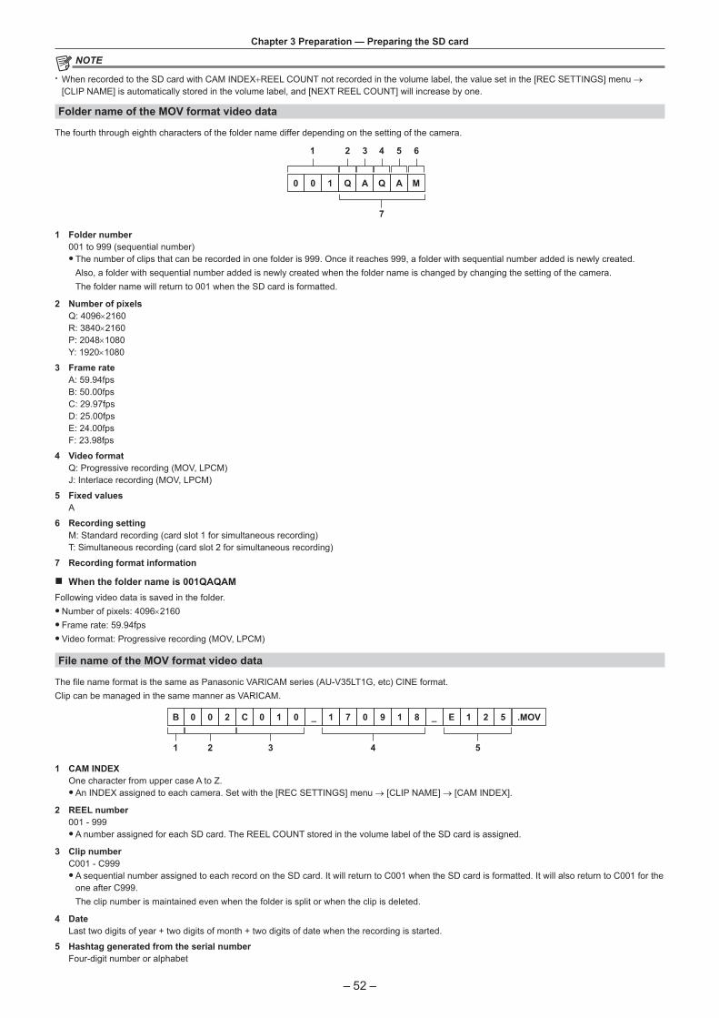
– 52 –
Chapter 3 Preparation — Preparing the SD card
@@ NOTE
t When recorded to the SD card with CAM INDEX+REEL COUNT not recorded in the volume label, the value set in the [REC SETTINGS] menu → [CLIP NAME] is automatically stored in the volume label, and [NEXT REEL COUNT] will increase by one.
Folder name of the MOV format video data
The fourth through eighth characters of the folder name differ depending on the setting of the camera.
0 0 1 Q A Q A M
1 2 3 4 5 6
7
1 Folder number001 to 999 (sequential number)
f The number of clips that can be recorded in one folder is 999. Once it reaches 999, a folder with sequential number added is newly created.Also, a folder with sequential number added is newly created when the folder name is changed by changing the setting of the camera.The folder name will return to 001 when the SD card is formatted.
2 Number of pixelsQ: 4096×2160R: 3840×2160P: 2048×1080Y: 1920×1080
3 Frame rateA: 59.94fpsB: 50.00fpsC: 29.97fpsD: 25.00fpsE: 24.00fpsF: 23.98fps
4 Video formatQ: Progressive recording (MOV, LPCM)J: Interlace recording (MOV, LPCM)
5 Fixed values A
6 Recording settingM: Standard recording (card slot 1 for simultaneous recording)T: Simultaneous recording (card slot 2 for simultaneous recording)
7 Recording format information
r When the folder name is 001QAQAMFollowing video data is saved in the folder.
fNumber of pixels: 4096×2160 f Frame rate: 59.94fps fVideo format: Progressive recording (MOV, LPCM)
File name of the MOV format video data
The file name format is the same as Panasonic VARICAM series (AU-V35LT1G, etc) CINE format.Clip can be managed in the same manner as VARICAM.
B 0 0 2 C 0 1 0 _ 1 7 0 9 1 8 _ E 1 2 5 .MOV
21 3 4 5
1 CAM INDEXOne character from upper case A to Z.
fAn INDEX assigned to each camera. Set with the [REC SETTINGS] menu → [CLIP NAME] → [CAM INDEX].
2 REEL number001 - 999
fA number assigned for each SD card. The REEL COUNT stored in the volume label of the SD card is assigned.
3 Clip numberC001 - C999
fA sequential number assigned to each record on the SD card. It will return to C001 when the SD card is formatted. It will also return to C001 for the one after C999.The clip number is maintained even when the folder is split or when the clip is deleted.
4 DateLast two digits of year + two digits of month + two digits of date when the recording is started.
5 Hashtag generated from the serial numberFour-digit number or alphabet

– 53 –
Chapter 3 Preparation — Preparing the SD card
@@ NOTE
t The clip name of the card slot 2 will be the same as the clip name of the card slot 1 for the simultaneous recording. t The maximum number of folder and the folder number is 999. The recording is prohibited when it reaches 999 even if number in between is open. t Number of clips that can be recorded on a single SD card is approximately 4000. Data will not be able to record when it reaches the maximum number of clips that can recorded even if number in between is open.

– 54 –
Chapter 3 Preparation — Setting of time data
Setting of time dataThe camera provides time code, user bits, and date and time (real time) data as time data, and records in each frame synchronized with the video. The time data is also recorded as the clip meta data.
Definition of time data
r Time code[FREE RUN] and [REC RUN] can be switched with the [REC SETTINGS] menu → [TC] → [FREE/REC RUN].
f [FREE RUN]: Advances regardless of the operation mode. It is advancing even when the power is turned off, so it can be treated equally as time. It can also be recorded to the time code input to the <TC IN/OUT> terminal using slave lock. f [REC RUN]: Advances only while recording. Recording is started with the value continuing from the last time code recorded previously.
@@ NOTE
t The [REC RUN] will not be a continuous value for following cases.‑ When deleting recorded clips‑ When recording is interrupted due to a malfunction of [REC WARNING], etc. during recording.
t It will be fixed to [FREE RUN] when pre-recording is enabled. t It will be fixed to [REC RUN] when the variable frame rate recording function is enabled. t It will be fixed to [REC RUN] when the interval recording function is enabled.
r User bitsUser bits are built-in. User bits are recorded in the clip. Also, it is output as LTC UB, VITC UB of the SDI signal.The user setting value, time, date, frame rate information during shooting, or clip name can be selected for recording.The value at the time when the recording has started is recorded in the user bits of the clip meta data.
r Duration (clip length) counterThis counter counts from 0 each time recording starts.The duration of the recorded clip is displayed after recording.
r Date/time (real time) f The internal clock will be the reference for the measurement of the free run time code while the power is set to < > (standby), time of the user bits, and date data. Also, it will be the reference for the file generation time and file name when the clip is recorded.
@@ NOTE
t The display in the VIEW screen and the HOME screen is switched with the [REC SETTINGS] menu → [TC] → [TC/UB/Dur.].
User bits settingsSet the user bits to be recorded.
1 From the [REC SETTINGS] menu → [TC] → [UB MODE], select the user bits to be recorded.
[FRAME RATE] Records the frame rate information of the shooting.Use with this setting when using the frame rate information of the user bits with an editing device such as a PC.Use this setting to control the recording operation in TYPE1 or TYPE2 method against the Panasonic recorder (AJ-PG50, etc.).
[USER] Records the user bits set in the [REC SETTINGS] menu → [TC] → [SET UB]. The setting value is maintained even when the power is set to < > (standby).For details, refer to “How to input user bits”.
[TIME] Records the hour, minute, and second of the date and time measured with the internal clock.
[DATE] Records the last two digits of year, month, date, and hour of the date and time measured with the internal clock.
[CLIP NAME] Records the value that CAM INDEX (one character) and REEL COUNT (three-digit number) both converted to ASCII character code.
How to input user bits
By setting user bits, information such as memos (date, time) up to eight digits long (hexadecimal) can be recorded.
1 Select the [REC SETTINGS] menu → [TC] → [UB MODE] → [USER].
2 Select the [REC SETTINGS] menu → [TC] → [SET UB].The user bits setting screen is displayed.
3 Set the user bits. fSet two digits each.
4 Confirm the setting value of the user bits. f The setting value is confirmed when last two digits are set.

– 55 –
Chapter 3 Preparation — Setting of time data
Memory function of the user bits
Setting contents of the user bits is automatically recorded, and it is maintained even if the power is set to < > (standby).
Frame rate informationThe relationship between frame rate, image pull-down, time code, and user bits is as follows.
Verification information on the right-hand six digits
Fixed values
REC mark
Camera video mode
Frame rate
r Camera video modeThe display of the camera video mode differs depending on the setting of following menus.
f The [SYSTEM SETTINGS] menu → [SYSTEM MODE] → [FREQUENCY] f The [CAMERA SETTINGS] menu → [FPS] → [VFR SW]
[FREQUENCY]Display of camera video mode
When [VFR SW] is set to [ON] When [VFR SW] is set to [OFF][23.98p] D C
[24.00p] F E
[29.97p] 9 8
[59.94p] 9 8
[25.00p] B A
[50.00p] B A
[59.94i] — 0
[50.00i] — 2
Setting the time code
1 Select the [SYSTEM SETTINGS] menu → [SYSTEM MODE] → [FREQUENCY] → [59.94i]/[59.94p]/[29.97p].
2 Select the [REC SETTINGS] menu → [TC] → [DF/NDF] → [DF]/[NDF].[DF]: Advances the time code in the drop frame mode.[NDF]: Advances the time code in the non-drop frame mode.
3 Select the [REC SETTINGS] menu → [TC] → [SET TC].The [SET TC] screen is displayed.
4 Set the time code.
5 Confirm the setting value of the time code. f The setting value is confirmed when last two digits are set.
r Setting range of time codeThe range of time code that can be set differs depending on [FREQUENCY].
[FREQUENCY] Range of the time code that can be set59.94p, 29.97p, 59.94i 00:00:00:00 - 23:59:59:29
23.98p, 24.00p 00:00:00:00 - 23:59:59:23
50.00p, 25.00p, 50.00i 00:00:00:00 - 23:59:59:24
@@ NOTE
t The set change is not reflected if the time code setting screen is closed without confirming the setting value. t Set the number of frames with the value that is multiple of four when [FREQUENCY] is set to 23.98p or 24.00p. The recorded time code will shift with any other value.
Time code function during battery replacement
The operation of the time code generator will continue by the backup mechanism functioning even when replacing the battery.The time code of the free run may shift when any item in the [SYSTEM SETTINGS] menu → [SYSTEM MODE] is changed. Set the power to < > (ON) again, confirm the time code, and set it again if necessary.

– 56 –
Chapter 3 Preparation — Setting of time data
Time code with variable frame rate record
The time code is fixed to [REC RUN] when the variable frame rate recording function is set to enable. The time code will advance in the speed corresponding to the ratio setting values of [FREQUENCY] (system frequency) and [FPS] (frame rate).As an example, the time frame will advance 60/24 frames (two seconds 12 frames) per second when [FREQUENCY] is set to [24.00p] and [FPS] is set to [60fps].
f The time code output from the <TC IN/OUT> terminal or the <SDI OUT> terminal is advanced in 1x speed from the exact start of recording.
Presetting the time code to externalThe internal time code generator of the camera can be slave locked in a simplified manner to an external generator.
Connection example of the camera and an external generator
Connect the reference time come to the <TC IN/OUT> terminal.〈TC IN/OUT〉端子
Reference time code
External lock
Externally lock the time code. fConnect the camera to an external generator in advance.
1 Select the [REC SETTINGS] menu → [TC] → [FREE/REC RUN] → [FREE RUN].
2 Select the [REC SETTINGS] menu → [TC] → [TC IN/OUT SEL] → [TC IN].
3 Enter the external time code to the <TC IN/OUT> terminal.[TC] in the HOME screen and the VIEW screen will be displayed in black and white inversion.Enter the time code matching the setting in the [SYSTEM SETTINGS] menu → [SYSTEM MODE] → [FREQUENCY] as the reference time code.Also, enter the time code of the non-drop frame for 23.98p, 24.00p, 25.00p, 50.00p, and 50.00i.
@@ NOTE t Do not slave lock to the externally input time code but automatically advance with internal reference during recording or rec remote controlling of the external recording device.The time code value may overlap or drop out after recording or ending rec remote due to performing slave lock to the time code input from external.
t Since this camera does not have a genlock system, the time code may shift one frame. t Once the slave lock is performed, it will maintain the slave lock status even when the input from the <TC IN/OUT> terminal is gone. However, the slave lock status will be cleared in following cases.‑ When the time code is set in [SET TC]‑ When the power is turned off‑ When switched [DF]/[NDF]‑ When set to [REC RUN]‑ When the variable frame rate recording function is enabled
t The pre-recording will be discarded once when the slave lock is performed during pre-recording. t The number of frames for the record start time code may not be multiple of four when [FREQUENCY] is set to 23.98p or 24.00p. t External locks by user bits are not supported.
Cautions when switching the power supply from the battery to the AC adaptor while an external lock is active
To maintain the continuity of the time code generator power, remove the battery only after that the power status display in the HOME screen has changed to after connecting the AC adaptor to the <DC IN 12V> terminal. The continuity of the external lock of the time code is not guaranteed when the battery is removed first.

– 57 –
Chapter 3 Preparation — Setting of time data
Supplying the time code externallyThe time code output from the camera corresponding to the camera video or the playback video can be supplied to an external recording device.
<TC IN/OUT> terminal
<SDI OUT> terminal
SDI IN terminal
TC IN terminal
VTR, etc.
1 Select the [REC SETTINGS] menu → [TC] → [TC IN/OUT SEL] → [TC OUT].
2 Select the [REC SETTINGS] menu → [TC] → [TC OUT REF] → [RECORDING].The same time code can be recorded to the video of the same time on two devices.
r To match the time code output from the <TC IN/OUT> terminal to the video of the SDI output or the monitor output
1 Select the [REC SETTINGS] menu → [TC] → [TC OUT REF] → [SDI OUT].
@@ NOTE
t TCR is output during playback. TCG output during playback is not supported. t When [FREQUENCY] is [23.98p] or [24.00p], time code output may be off by 1 frame. t External locks by user bits are not supported.

– 58 –
Chapter 3 Preparation — Assigning function to the USER buttons
Assigning function to the USER buttonsSelected function can be assigned to the USER buttons.
f The buttons that can be used as a USER button are as follows. - <USER 1> to <USER 9> buttonsThese can be used as the USER buttons when the VIEW screen is displayed.
- Multidial (when <WB>/<USER>/<ISO/dB> switch is set to <USER>)
1 From the [SYSTEM SETTINGS] menu → [USER SWITCHES] → [USER1] to [USER9] or [USER TOGGLE], select the function to assign to each.
r Functions assigned to the USER buttons in the factory setting
USER button Function<USER 1> button [ONE PUSH AF]
<USER 2> button [PEAK./SQUARES F.A.]
<USER 3> button [SPOT METER]
<USER 4> button [E.I.S.]
<USER 5> button [WFM]
<USER 6> button [AWB]
<USER 7> button [SLOT SEL]
<USER 8> button [EXPAND]
<USER 9> button [OPEN IRIS F.A.]
Multidial [MONITOR VOL]
Functions assigned to USER buttons
Function assigned to <USER 1> to <USER 9> buttons
Item Description[INHIBIT] Disables assignment of functions.
[AWB] Enables/disables the auto white balance.
[ONE PUSH AF] Assigns the one-push auto focus function.
[ONE PUSH A.IRIS] Assigns the one-push auto iris function.
[ATW LOCK] Fixes the value of the white balance. Pressing the USER button again will resume the operation of the auto tracking white balance.
f Enable when the auto tracking white balance is operating.
[E.I.S.] Enables/disables the electronic image stabilization function.
[D.ZOOM] Enables/disables the digital zoom. It will zoom the angle of view 1.4 times both vertically and horizontally.
[IR SHOOTING] Enables/disables the IR recording.
[REC SW] Starts or stops the recording.
[PRE REC] Enables/disables the pre-recording.
[VFR] Enables/disables the variable frame rate recording function.
[REC CHECK] Automatically plays back the last approximately three seconds of the previously shot clip.
[DEL LAST CLIP] Deletes the clip last shot.
[SLOT SEL] Selects the card slot with the SD card to record inserted.Or, switches the card slot for the clip to display in the thumbnail screen.
[EXPAND] Enables/disables the enlarged display function (focus assist function).
[OPEN IRIS F.A.] Assigns the open iris focus assist function (focus assist function).
[PEAK./SQUARES F.A.] Enables/disables the peaking function and focus square display (focus assist function).The display is selected in the [OUTPUT SETTINGS] menu → [LCD FOCUS ASSIST] → [PEAK./SQUARES MODE].
[WFM] Switches the display of the waveform monitor. The waveform display is selected in the [OUTPUT SETTINGS] menu → [LCD EI ASSIST] → [WFM MODE].
[SPOT METER] Displays/hides the spot meter.This is enabled when the [OUTPUT SETTINGS] menu → [SDI/HDMI INDICATOR]/[LCD INDICATOR] → [SPOT METER] → [ON] is set.
[ZEBRA] Displays/hides zebra patterns.
[LEVEL GAUGE] Displays/hides the level gauge.
[LEVEL GAUGE SET] Sets the current horizontal and vertical direction as the reference value of the level gauge.
[SDI COLOR] Switches the output image from the <SDI OUT> terminal.
[HDMI COLOR] Switches the output image from the <HDMI> terminal.
[LCD COLOR] Switches the output image from the <LCD> terminal.
[SDI OUT HDR] Switches the high dynamic range/standard dynamic range for the output image from the <SDI OUT> terminal.
[HDMI OUT HDR] Switches the high dynamic range/standard dynamic range for the output image from the <HDMI> terminal.
[LCD HDR] Switches the high dynamic range/standard dynamic range for the output image from the <LCD> terminal.
[LCD CLEAN VIEW] Erases the display of the indicator or marker superimposed to the output video from the <LCD> terminal.

– 59 –
Chapter 3 Preparation — Assigning function to the USER buttons
Item Description[LCD MARKER] Displays/hides the marker superimposed in the output video from the <LCD> terminal.
[COLOR BARS] Displays/hides the color bars.
[LOAD SETUP FILE] Selects the setup file saved in the SD card and reads it into the camera.
[POWER LCD] Make it easier to view the LCD monitor in a well-lighted area such as outdoor.
@@ NOTE
t Following functions will be disabled when the camera is set to < > (standby) and then turned on again.[ATW LOCK], [D.ZOOM], [EXPAND], [PEAK./SQUARES F.A.], [WFM], [SPOT METER], [LCD CLEAN VIEW], [COLOR BARS], [POWER LCD]
t Following functions will be enabled when the camera is set to < > (standby) and then turned on again.[LCD MARKER]
Functions assigned to the multidial
When <WB>/<USER>/<ISO/dB> switch is set to <USER>, the multidial can be used as a USER button. f The operation as the USER button is enabled when the VIEW screen is displayed.
Item Description[INHIBIT] Disables assignment of functions.
[SHUTTER] Enables/disables the shutter function when the multidial is pressed.The setting value of the shutter speed can be selected by turning the multidial.
[FPS] Enables/disables the variable frame rate record function when the multidial is pressed.The setting value of the frame rate can be selected by turning the multidial.
[MONITOR VOL] The adjustment of the audio level output from the headphones terminal is enabled when the multidial is pressed. The level meter for adjusting is displayed in the LCD monitor when it is enabled.The level of the audio can be adjusted by turning the multidial. Level adjustment of audio is ended by pressing the multidial again.
Checking the function assigned to the USER buttons
1 Press the <HOME> button.The HOME screen is displayed.
2 Press the <INFO> button.The INFO screen is displayed.
3 Select [SWITCHES]. The function assigned to each USER button is displayed.
f In addition to operating with the multidial and touch operations, the function can be selected by pressing the <INFO> button.

– 60 –
Chapter 3 Preparation — Tally lamp
Tally lampThe front tally lamp and the rear tally lamp can be illuminated during the shooting.
1 Select the [SYSTEM SETTINGS] menu → [LED & FAN] → [TALLY LED] → [FRONT]/[REAR]/[BOTH]. f The tally lamp will flash when the camera is in the following status.‑ When the remaining capacity of the SD card or the remaining battery level is low (one time per second)‑ The SD card has no more space to record (four times per second)‑ When a warning such as a system error or a recording abnormality has occurred (four times per second)
@@ NOTE
t The tally lamp will not illuminate or flash when the [SYSTEM SETTINGS] menu → [LED & FAN] → [TALLY LED] → [OFF] is set.

This chapter describes how to operate the screen of this camera, how to operate the menu, the structure of the menu, and details of the menu.
Chapter 4 Operation

– 62 –
Chapter 4 Operation — Basic operation of the screen
Basic operation of the screen
Major button operation and screen display
1
23
4
1 <VIEW> button2 <INFO> button3 <THUMBNAIL> button4 <HOME> button
r <VIEW> buttonDisplays the VIEW screen.Displays the shooting screen.The VIEW screen is displayed when the camera is turned on.For details of the VIEW screen, refer to “Screen status display”.
r <INFO> buttonDisplays the INFO screen.Information of the camera can be confirmed.For details of the INFO screen, refer to “INFO screen”.
r <THUMBNAIL> buttonDisplays the thumbnail screen.Playback, copy, delete, or protect of a clip can be performed.For details of the thumbnail screen, refer to “Thumbnail operation”.
r <HOME> buttonDisplays the HOME screen.Sets the basic setting of the camera, or checks the status of the camera.For details of the HOME screen, refer to “HOME screen”.

– 63 –
Chapter 4 Operation — Basic operation of the screen
Major button operation and switching screenSwitches the screen as follows when the <HOME> button, <INFO> button, <VIEW> button, or <THUMBNAIL> button is pressed.
1
3 4 1
3
3
3 1
22
1
4
Thumbnail screen
VIEW screen
HOME screen
INFO screenClip information
1 <HOME> button2 <VIEW> button3 <THUMBNAIL> button4 <INFO> button
@@ NOTE
t The VIEW screen is displayed when the camera is turned on. t Switches to the VIEW screen automatically when the recording is started.If the recording is started while displaying the HOME screen, the screen will automatically switch to the HOME screen when the recording is stopped.
t Pressing the <HOME> button will switch between the HOME screen and the VIEW screen. t The screen will not switch to the thumbnail screen when the [SYSTEM SETTINGS] menu → [SYSTEM MODE] → [SDI RAW] is set to anything other than [OFF].

– 64 –
Chapter 4 Operation — Displaying the HOME screen
Displaying the HOME screenStatus of the camera can be confirmed.
1 7 8 9 10
13 14 15 16 17 18
11 122 3
4 5 6
1 [FPS]Displays the setting status of the variable frame rate recording function and the recording frame rate.
2 [COLOR]Displays the color setting of the video recorded to the main recorder.
3 [SHUTTER]Displays the shutter speed.[sec]: Displays in time.[deg]: Displays at shutter open angle.
4 [EI]Displays the EXPOSURE INDEX (gain).[ISO] and [dB] can be switched with the [CAMERA SETTINGS] menu → [EI] → [MODE].
5 [AUDIO]Displays the status of the audio input for audio channel 1 and the audio channel 2.[IN1]: The <AUDIO INPUT 1> terminal is selected as the audio input.[IN2]: The <AUDIO INPUT 2> terminal is selected as the audio input.[MIC]: An external microphone is selected as the audio input.[LINE]: An audio device is selected as the audio input.[INT(L)]: The built-in microphone <L> is selected as the audio input.[INT(R)]: The built-in microphone <R> is selected as the audio input.[48V]: The external microphone power supply is enabled.
6 [WB]Displays the color temperature (white balance).When the adjusted value acquired by the auto white balance is [AWB MEMORY A], the color temperature is displayed with [A] at the beginning. When the adjusted value acquired by the auto white balance is [AWB MEMORY B], the color temperature is displayed with [B] at the beginning.[ATW]: Displays while the auto tracking white balance is operating.[ATW LOCK]: Displays when the auto tracking white balance is locked.
7 Number of recorded pixels/system frequencyDisplays the number of recording pixels and the system frequency.When the [SYSTEM SETTINGS] menu → [SYSTEM MODE] → [SDI RAW] is set to anything other than [OFF], the RAW output resolution and the system frequency from <SDI OUT> terminal are displayed.
8 Pre-recording status displayDisplays the re-recording status.
: When the [REC SETTINGS] menu → [PRE REC] → [ON] is set and pre-recording is enabled (No display): When the [REC SETTINGS] menu → [PRE REC] → [OFF] is set, or when pre-recording is unable
9 Card slot 1/card slot 2 status displayIndicates the insertion status, current recording target, and remaining recordable capacity of the SD card.
: When the SD card is inserted, and it is set as the recording target: When the SD card is inserted, but it is not set as the recording target
[0min]…[999min]: Remaining recordable capacity (0 - 999 minutes, 999 minutes or more is displayed as [999min])[END]: When there is no remaining recordable capacity[WP]: When the write protect switch of the SD card is set to the LOCK side[!SDXC]: When the SDHC memory card is inserted, and the [SYSTEM SETTINGS] menu → [SYSTEM MODE] → [MAIN CODEC] is set to a file in MOV format (displayed in red) [ERR]: When a recording media that cannot be recorded is inserted (displayed in red)(No display): When the SD card is not inserted, or when the [SYSTEM SETTINGS] menu → [SYSTEM MODE] → [SDI RAW] is set to anything other than [OFF]
10 Special recording function displayDisplays the setting and enable/disable status of the special recording function of each card slot.[RELAY]: When set to relay recording[SIMUL]: When set to simultaneous recording[INTRVL]: When set to interval recording

– 65 –
Chapter 4 Operation — Displaying the HOME screen
11 Wireless LAN connection status displayDisplays the connection status of the wireless LAN.(No display): When the [NETWORK SETTINGS] menu → [NETWORK SEL] → [OFF] is set
: When ROP is not connected: When ROP is connected
12 Power status displayDisplays the remaining battery level, or the drive status of the AC adaptor.
: Driving with the battery (remaining battery level): Driving with the AC adaptor
13 Main recording codecDisplays the recording codec of the main recorder.[ONLY SDI RAW]: When the [SYSTEM SETTINGS] menu → [SYSTEM MODE] → [SDI RAW] is set to anything other than [OFF]
14 Warning/alert display (page 174): Warning display: Alert display
15 Time code display[TCG **:**:**:**]: Displays the value of the time code generator[UBG ** ** ** **]: Displays the value of the user bits generator[Dur. **:**:**:**]: Displays the value of the duration
16 Audio level meterDisplays the recording level of audio with 18 bars. (2 dB steps)Displays in red bar when exceeding 0 dB.
: During a mode that cannot record audio such as when the variable frame rate recording function is enabled and the set frame rate is different from the system frequency
17 External output terminal output image setting displayDisplays the output image of the external output terminal set in the [SYSTEM SETTINGS] menu → [COLOR SETTINGS] → [SDI OUT]/[HDMI OUT]/[LCD OUT].The output image of the external output terminal set in following menu is displayed when set to the [SYSTEM SETTINGS] menu → [COLOR SETTINGS] → [MAIN] → [SCENE1] to [SCENE5] and the [SCENE FILE SETTINGS] menu → [GAMMA] → [GAMMA SELECT] → [HLG].
f [OUTPUT SETTINGS] menu → [SDI OUT] → [SDI OUT HDR] f [OUTPUT SETTINGS] menu → [HDMI OUT] → [HDMI OUT HDR] f [OUTPUT SETTINGS] menu → [LCD HDR]
When the [SYSTEM SETTINGS] menu → [SYSTEM MODE] → [SDI RAW] is set to anything other than [OFF], [RAW] is displayed in [SDI].
18 CAM INDEX/REEL COUNTDisplays the CAM INDEX, REEL COUNT, and clip number. Information about last recorded clip is displayed.
: CAM INDEX and REEL COUNT (A001 to Z999): Clip number (C001 to C999)

– 66 –
Chapter 4 Operation — Operating each screen
Operating each screenThe HOME screen, which is the starting point of screen operation is displayed by pressing the <HOME> button.Display the HOME screen, select [FPS], [COLOR], [SHUTTER], [EI], [AUDIO], or [WB], and change the value, etc., in the displayed screen.
f There is a method to operate with the multidial or a grip multidial, or a method to operate by touching the LCD monitor.
HOME screenSets the basic setting of the camera.
1
4 5 6
2 3
1 [FPS]2 [COLOR]3 [SHUTTER]4 [EI]5 [AUDIO]6 [WB]
[FPS]
The FPS screen is displayed when [FPS] is selected in the HOME screen, allowing to select the frame rate and enable/disable the variable frame rate recording function.
[VALUE]: The VIEW screen is displayed and the frame rate can be selected. fSelect from the previously registered frame rate setting values in [`]/[{]. f The frame rate setting value can be added/deleted in the [CAMERA SETTINGS] menu → [FPS] → [ADD]/[DELETE]. Maximum of 150 setting values (128 for [25.00p]/[50.00p]) can be registered.
[VFR]: Enables/disables the variable frame rate recording function.
@@ NOTE
t When the [CAMERA SETTINGS] menu → [FPS] → [VFR SW] → [OFF] is set, [VALUE] in the FPS screen cannot be selected. t When the recording mode is set to AVCHD, or when [FREQUENCY] is set to [50.00i]/[59.94i], [FPS] in the HOME screen cannot be selected.

– 67 –
Chapter 4 Operation — Operating each screen
r [VFR] displayWhen the [CAMERA SETTINGS] menu → [FPS] → [VFR SW] → [ON] is set, [VFR] is displayed at the top left of [FPS], and recorded with the frame rate set in [FPS]. Audio cannot be recorded when [FREQUENCY] and [FPS] are different.When the [CAMERA SETTINGS] menu → [FPS] → [VFR SW] → [OFF] is set, [VFR] is not displayed. Records in the 1x speed of the rate set in the [SYSTEM SETTINGS] menu → [SYSTEM MODE] → [FREQUENCY].
[COLOR]
When [COLOR] is selected in the HOME screen, the COLOR screen is displayed allowing to set the color of the image (gamma and gamut).
[MAIN COLOR]: Sets the color of video recorded in the main recorder (entire camera system).[SDI OUT]: Sets the output image from the <SDI OUT> terminal.[HDMI OUT]: Sets the output image from the <HDMI> terminal.[LCD OUT]: Sets the output image from the <LCD> terminal.When [MAIN COLOR] is set to [SCENE1] to [SCENE5], and the [SCENE FILE SETTINGS] menu → [GAMMA] → [GAMMA SELECT] → [HLG] is set, [SDI OUT HDR]/[HDMI OUT HDR]/[LCD HDR] is displayed instead of [SDI OUT]/[HDMI OUT]/[LCD OUT]. [COLOR/HDR] is displayed instead of [COLOR] in the HOME screen.[SDI OUT HDR]: Sets the high dynamic range/standard dynamic range of the output image from the <SDI OUT> terminal.[HDMI OUT HDR]: Sets the high dynamic range/standard dynamic range of the output image from the <HDMI> terminal.[LCD HDR]: Sets the high dynamic range/standard dynamic range of the output image from the <LCD> terminal.
@@ NOTE
t When the [SYSTEM SETTINGS] menu → [SYSTEM MODE] → [SDI RAW] is set to anything other than [OFF], [MAIN COLOR] is fixed to [V-Log]. t [SDI OUT]/[HDMI OUT]/[LCD OUT] settings ‑ When [MAIN COLOR] is set to [V-Log]
You can select [V-Log] or [V-709]. ‑ When [MAIN COLOR] is set to [SCENE1] to [SCENE5]
Setting will be same as [MAIN COLOR]. ‑ When the [SYSTEM SETTINGS] menu → [SYSTEM MODE] → [SDI RAW] is set to anything other than [OFF], [RAW] is displayed in [SDI OUT], and
it cannot be selected. [V-Log] and [V-709] can be selected in [HDMI OUT]/[LCD OUT].
[SHUTTER]
The SHUTTER screen is displayed when [SHUTTER] is selected in the HOME screen, allowing to set the shutter speed and enable/disable the shutter function.
[VALUE]: The VIEW screen is displayed, and the shutter speed can be set. fSelect from the previously registered shutter speed setting values in [`]/[{]. f The shutter speed setting value can be added/deleted in the [CAMERA SETTINGS] menu → [SHUTTER] → [ADD deg]/[ADD sec]/[DELETE deg]/[DELETE sec]. Maximum of 12 setting values can be registered.
[ON/OFF]: Enables/disables the shutter function.

– 68 –
Chapter 4 Operation — Operating each screen
@@ NOTE
t When the [CAMERA SETTINGS] menu → [SHUTTER] → [SW] → [OFF] is set, [VALUE] in the SHUTTER screen cannot be selected.
[EI]
The EI screen is displayed when [EI] is selected in the HOME screen, allowing to set EXPOSURE INDEX (gain), and to set the operation in accordance with the setting of the [CAMERA SETTINGS] menu → [EI] → [MODE].
[NATIVE ISO]/[800BASE ISO]/[2500BASE ISO]/[GAIN SELECT]: The VIEW screen is displayed, and EXPOSURE INDEX (gain) can be set. fSet EXPOSURE INDEX (gain) with [`]/[{].
[ISO SELECT]/[GAIN MODE]: The VIEW screen is displayed and the operation in accordance with the setting of the [CAMERA SETTINGS] menu → [EI] → [MODE] can be set.
[AUDIO]
When [AUDIO] is selected in the HOME screen, the AUDIO screen is displayed, allowing to set the shutter speed.
[CH1 IN]: Sets the audio to be recorded in the audio channel 1.[CH2 IN]: Sets the audio to be recorded in the audio channel 2.[INPUT1 SEL]: Sets the audio input signal from the device connected to the <AUDIO INPUT 1> terminal.[INPUT2 SEL]: Sets the audio input signal from the device connected to the <AUDIO INPUT 2> terminal.
[WB]
When [WB] is selected in the HOME screen, the VIEW screen is displayed, allowing to set the color temperature (white balance). fSelect from the previously registered white balance setting values in [`]/[{]. f The white balance setting value can be added/deleted in the [CAMERA SETTINGS] menu → [WHITE] → [ADD]/[DELETE]. Maximum of 13 setting values can be registered.

– 69 –
Chapter 4 Operation — Operating each screen
INFO screenDisplays the information of the camera.This is displayed when the <INFO> button is pressed while displaying the HOME screen.
f In addition to operating with the multidial and touch operations, each item can be selected by pressing the <INFO> button.
[DIAGNOSTICS]: Displays the status of the camera, such as warning.[SWITCHES]: Displays the assignment status of each USER button.[VERSION]: Displays the model name, serial number, and firmware version.[NETWORK]: Displays the setting value and connection status of the wireless LAN.[AUDIO]: Displays the audio setting and selection status of each recording channel.[MEDIA]:Displays the information of the SD card.
VIEW screenDisplays the shooting screen.For details of the VIEW screen, refer to “Screen status display”.
Thumbnail screenPlayback, copy, delete, or protect of a clip can be performed.For details of the thumbnail screen, refer to “Thumbnail operation”.

– 70 –
Chapter 4 Operation — Basic operation of the menu
Basic operation of the menuThe setting of the camera can be changed with the menu in accordance to the shooting scene or recording contents.Set data is written and saved in the camera memory.
f There is a method to operate with the multidial or a grip multidial, or a method to operate by touching the LCD monitor.
Configuration of the menu
Menu types and how to open them
Menu type Use How to openMenu The menu is structured in categorized levels according to
intended use and setting frequency.Displayed by pressing the <MENU> button.Displayed by touching the LCD monitor for one second or more and releasing it while the VIEW screen is displayed.
[OPTION] menu A special menu is prepared considering additional functions in the future.
Displayed by pressing the <MENU> button while holding down the <EXIT> button.
Configuration of the menu
[THUMBNAIL] menu Performs confirmation or deleting of the recording clip.This menu can be set when the thumbnail screen is displayed.
[SYSTEM SETTINGS] menu Sets the system in general.
[CAMERA SETTINGS] menu Sets the basic function of the camera.This menu cannot be set when the thumbnail screen is displayed.
[SCENE FILE SETTINGS] menu Sets the setting regarding scene file.This menu sets the detailed image quality adjustment of the camera video. Also, selection of the scene file, writing the scene file data to the camera memory, and reading from the camera memory can be performed.This menu cannot be set when the thumbnail screen is displayed.
[REC SETTINGS] menu Sets the various items in the recording function.
[AUDIO SETTINGS] menu Sets the input/output function of audio.
[OUTPUT SETTINGS] menu Sets the display content or output format of the video.
[FILE] menu Saves and reads the setting data.
[NETWORK SETTINGS] menu Sets the setting regarding the network function.

– 71 –
Chapter 4 Operation — Basic operation of the menu
Displaying the menuDisplays the menu, and select the menu or item to set.
1 Press the <MENU> button when not recording.The menu is displayed.
1
4
5
2
3
1 Level displayDisplays the path of the menu to the currently displayed screen.
2 [`]/[{]Moves the cursor up or down when selected.
3 Returns to one level higher from the current menu when selected.
4 MenuMoves to one level lower from the current menu, or to the setting screen when selected.
5 [SET]Confirms the set value when selected.
@@ NOTE
t The menu displayed in gray characters cannot be changed.

– 72 –
Chapter 4 Operation — Basic operation of the menu
Operating the menuVarious settings are possible from the menu.There are two methods of operation, a method to operate with the multidial or grip multidial, or a method to touch the LCD monitor.
When operating with the multidial
Operate the multidial on the camera by turning it in vertical direction or pushing it.
Fig. 1 Fig. 2
1 Press the <MENU> button when not recording.The menu is displayed.
2 Select the menu to set.
1) Turn the multidial to move the cursor to the menu to set.
2) Press the multidial.
The lower level menu is displayed. f The confirmation screen is displayed depending on the menu. fPerform the similar operation if there is next level. f In some menus, a screen to set the numeric value is displayed in the VIEW screen (Fig. 2). f In some menus, a message is displayed if a menu cannot be executed. f To return to one level higher, press the <EXIT> button.
3 Select the item to set.
1) Turn the multidial to move the cursor to the item to set.
2) Press the multidial.
A check mark is displayed at the left of the set item. (Fig. 1) f To return to one level higher, press the <EXIT> button.
4 Press the <MENU> button to close the menu. fDepending on the operating item, it will automatically return to the previous screen.
@@ NOTE
t In a screen to set the numeric value (Fig. 2), turn the multidial in your desired direction with the multidial pushed in, and hold it to change the value with high speed.
t The grip multidial operates equally as the multidial on the camera.

– 73 –
Chapter 4 Operation — Basic operation of the menu
When operating by touching the LCD monitor
Operate by touching the LCD monitor.
1 Press the <MENU> button when not recording.The menu is displayed.
fMenu is displayed even when the LCD monitor is touched for one second or longer and then released while the VIEW screen is displayed.
2 Select the menu to set. f Touch the menu to set. The lower level menu is displayed. f The confirmation screen is displayed depending on the menu. fPerform the similar operation if there is next level. f In some menus, a screen to set the numeric value is displayed in the VIEW screen.To change the numeric value, touch [`]/[{] and change the setting value. f In some menus, a message is displayed if a menu cannot be executed. f The cursor is moved up or down by touching [`]/[{]. f To return to one level higher, touch .
3 Select the item to set. f Touch the item to set. A check mark is displayed at the left of the set item. f To return to one level higher, touch .
4 Exit from the menu by touching , or pressing the <MENU> button. fDepending on the operating item, it will automatically return to the previous screen.
Initializing the menuThe menu can be returned to the factory setting condition.
1 Select the [SYSTEM SETTINGS] menu → [INITIALIZE] → [LOAD FACTORY DATA]. The setting value of the menu is returned to the factory setting.

– 74 –
Chapter 4 Operation — Menu setting contents
Menu setting contents
[THUMBNAIL] menuPerforms confirmation or deleting of the recording clip. This menu can be set when the thumbnail screen is displayed.
[PLAYBACK]
[SLOT SEL]Selects a clip to be displayed on the thumbnail screen.
[ALL SLOT] Displays the clips recorded on all the SD cards in each card slot.
[SLOT1] Displays only the clips recorded on the SD card in card slot 1.
[SLOT2] Displays only the clips recorded on the SD card in card slot 2.
(Factory setting: [ALL SLOT])
[RESUME PLAY]Select if the playback is to start from the position the playback has stopped or not.
[ON] Plays back from the position where playback has stopped.
[OFF] Always starts the playback from the beginning of the clip.
(Factory setting: [OFF])
[CLIP]
The clip can be protected or copied to a different SD card.
[PROTECT] [SELECT] Protect the clip so it is not mistakenly deleted.Select the clip to protect, and set the protect.
[DELETE] [ALL] Deletes all the clips displayed in the thumbnail screen.The clip that is not displayed in the thumbnail screen is not deleted.
[SELECT] Select the clip to delete, and delete it.
[COPY] [ALL] Copies all clips to a different SD card.
[SELECT] Select the clip to copy, and copies to a different SD card.
[INFORMATION] Displays the detailed information of the clip.
@@ NOTE
t The clip recorded in the MOV format cannot be copied.
[SYSTEM SETTINGS] menuSets the system in general.
[SYSTEM MODE]
For the combination that can be set, refer to “Selecting the resolution, codec, and frame rate for recording video”, “Selecting the resolution and frame rate of the RAW output”.
[FREQUENCY]Sets the system frequency.The items that can be set are as follows.
f [23.98p], [24.00p], [25.00p], [29.97p], [50.00p], [59.94p], [50.00i], [59.94i](Factory setting: [23.98p])
@@ NOTE
t The camera will restart when the setting is changed. t When the [SYSTEM SETTINGS] menu → [SYSTEM MODE] → [MAIN CODEC] is set to AVCHD format, different clips with system frequency in 59.94 Hz system (23.98p, 59.94p, 59.94i) and the ones in 50 Hz system (50.00p, 50.00i) cannot be recorded in a single SD card. Prepare an SD card for each system of system frequency (59.94 Hz system and 50 Hz system). [FORMAT ERROR CARD <SLOT 1>]/[FORMAT ERROR CARD <SLOT 2>] alert is displayed when the system frequency systems are different.
[SDI RAW]Sets the RAW output resolution from the <SDI OUT> terminal.
[OFF] Does not perform RAW output.
[S35 5.7K] Performs the RAW output of the 5760×3072 pixels using all the pixels of the image sensor.Allows shooting up to 30p.
[CROP 4K] Performs the RAW output of the 4096×2160 pixels by cutting out the center section of the image sensor.Allows shooting up to 60p. Angle of view will change.

– 75 –
Chapter 4 Operation — Menu setting contents
[CROP&MIX 2K] Performs the RAW output of the 2048×1080 pixels by cutting out the center section of the image sensor and performing the pixel mixing read.This allows high-speed shooting up to 240p. Angle of view will change.
(Factory setting: [OFF])
@@ NOTE
t When the [SYSTEM SETTINGS] menu → [SYSTEM MODE] → [FREQUENCY] is set to [50.00i]/[59.94i], this is fixed to [OFF]. t When the [SYSTEM SETTINGS] menu → [SYSTEM MODE] → [FREQUENCY] is set to [50.00p]/[59.94p], [S35 5.7K] cannot be selected. t Following conditions apply when set to anything other than [OFF].‑ Recording to an SD card with the camera is not possible.‑ The [SYSTEM SETTINGS] menu → [COLOR SETTINGS] → [MAIN] will be fixed to [V-Log].‑ The [CAMERA SETTINGS] menu → [EI] → [MODE] will be fixed to [ISO].‑ The thumbnail screen is not displayed.‑ [E.I.S.], [D.ZOOM], [PRE REC], [REC CHECK], [DEL LAST CLIP], [SLOT SEL], [SDI COLOR], and [COLOR BARS] assigned to the USER button
will not operate.‑ The [OUTPUT SETTINGS] menu → [SDI OUT] → [SDI REC REMOTE] and the [OUTPUT SETTINGS] menu → [HDMI OUT] → [HDMI REC
REMOTE] will not operate.‑ The time code information is not output in the image output from the <HDMI> terminal.
[SENSOR MODE]Sets the drive mode of the image sensor.
[S35 5.7K] Uses the entire pixels of the image sensor.
[S35 MIX 2.8K] Performs pixel mixing read of 2.8K from the entire image sensor.This allows high-speed shooting up to 120p.
[4/3 CROP&MIX 2.2K] Performs the pixel mixing read of 2.2K by cropping the Four Thirds image circle from the center of the image sensor.This allows high-speed shooting up to 240p. Angle of view will change.
(Factory setting: [S35 5.7K])
@@ NOTE
t When the [SYSTEM SETTINGS] menu → [SYSTEM MODE] → [SENSOR MODE] → [4/3 CROP&MIX 2.2K] is set‑ The sensitivity will be lower than when [S35 5.7K] or [S35 MIX 2.8K] is set.‑ The items that can be set in the [CAMERA SETTINGS] menu → [EI] → [NATIVE ISO] will be [400 ISO] or [1250 ISO].
t When the [SYSTEM SETTINGS] menu → [SYSTEM MODE] → [SDI RAW] is set to anything other than [OFF], this cannot be set.
[MAIN PIXEL]Sets the main recorder’s number of recording pixels.The items that can be set are as follows.
f [4096×2160], [3840×2160], [2048×1080], [1920×1080], [1280×720](Factory setting: [4096×2160])
@@ NOTE
t When the [SYSTEM SETTINGS] menu → [SYSTEM MODE] → [SDI RAW] is set to anything other than [OFF], this cannot be set.
[MAIN CODEC]Sets the recording codec of the main recorder.
fMOV file
[HEVC LongGOP 200M] 4:2:0 (10 bits) LongGOP 200 Mbps
[HEVC LongGOP 150M] 4:2:0 (10 bits) LongGOP 150 Mbps
[420LongGOP 150M] 4:2:0 (8 bits) LongGOP 150 Mbps
[420LongGOP 100M] 4:2:0 (8 bits) LongGOP 100 Mbps
[420LongGOP 50M] 4:2:0 (8 bits) LongGOP 50 Mbps
[422LongGOP 150M] 4:2:2 (10 bits) LongGOP 150 Mbps
[422LongGOP 100M] 4:2:2 (10 bits) LongGOP 100 Mbps
[422LongGOP 50M] 4:2:2 (10 bits) LongGOP 50 Mbps
[422ALL-I 400M] 4:2:2 (10 bits) ALL-Intra 400 Mbps
[422ALL-I 200M] 4:2:2 (10 bits) ALL-Intra 200 Mbps
[422ALL-I 100M] 4:2:2 (10 bits) ALL-Intra 100 Mbps
fAVCHD file
[AVCHD PS] 4:2:0 (8 bits) LongGOP 25 Mbps
[AVCHD PH] 4:2:0 (8 bits) LongGOP 21 Mbps
[AVCHD HA] 4:2:0 (8 bits) LongGOP 17 Mbps
[AVCHD PM] 4:2:0 (8 bits) LongGOP 8 Mbps
(Factory setting: [422LongGOP 150M])
@@ NOTE
t When the [SYSTEM SETTINGS] menu → [SYSTEM MODE] → [SDI RAW] is set to anything other than [OFF], this cannot be set.

– 76 –
Chapter 4 Operation — Menu setting contents
[COLOR SETTINGS]
[MAIN]Sets the colors of videos (entire camera system) recorded in the main recorder.
[V-Log] Sets to the gamma curve that can achieve gradation and wide latitude (exposure range). A grading process after recording is required.
[SCENE1], [SCENE2], [SCENE3], [SCENE4], [SCENE5]
Sets to setting to perform detailed image quality adjustment with the camera.When [SCENE1] to [SCENE5] is selected, the menu setting for the same scene number is enabled in the [SCENE FILE SETTINGS] menu.
(Factory setting: [V-Log])
@@ NOTE
t When the [SYSTEM SETTINGS] menu → [SYSTEM MODE] → [SDI RAW] is set to anything other than [OFF], this will be fixed to [V-Log].
[SDI OUT]Sets the output image from the <SDI OUT> terminal.
fWhen [MAIN] in [COLOR SETTINGS] is set to [V-Log]
[V-Log] Outputs with the same color as the video recorded in the main recorder.
[V-709] Outputs by converting to a color comparable to the standard CINE-LIKE. This is the setting appropriate for preview.
fWhen [MAIN] in [COLOR SETTINGS] is set to [SCENE1], [SCENE2], [SCENE3], [SCENE4], or [SCENE5]
[SCENE1], [SCENE2], [SCENE3], [SCENE4], [SCENE5]
Outputs with the same color as the video recorded in the main recorder. This cannot be changed.
(Factory setting: [V-Log])
@@ NOTE
t When the [SYSTEM SETTINGS] menu → [SYSTEM MODE] → [SDI RAW] is set to anything other than [OFF], this will be fixed to [V-Log].
[HDMI OUT]Sets the output image from the <HDMI> terminal.
fWhen [MAIN] in [COLOR SETTINGS] is set to [V-Log]
[V-Log] Outputs with the same color as the video recorded in the main recorder.
[V-709] Outputs by converting to a color comparable to the standard CINE-LIKE. This is the setting appropriate for preview.
fWhen [MAIN] in [COLOR SETTINGS] is set to [SCENE1], [SCENE2], [SCENE3], [SCENE4], or [SCENE5]
[SCENE1], [SCENE2], [SCENE3], [SCENE4], [SCENE5]
Outputs with the same color as the video recorded in the main recorder. This cannot be changed.
(Factory setting: [V-Log])
[LCD OUT]Sets the output image from the <LCD> terminal.
fWhen [MAIN] in [COLOR SETTINGS] is set to [V-Log]
[V-Log] Outputs with the same color as the video recorded in the main recorder.
[V-709] Outputs by converting to a color comparable to the standard CINE-LIKE. This is the setting appropriate for preview.
fWhen [MAIN] in [COLOR SETTINGS] is set to [SCENE1], [SCENE2], [SCENE3], [SCENE4], or [SCENE5]
[SCENE1], [SCENE2], [SCENE3], [SCENE4], [SCENE5]
Outputs with the same color as the video recorded in the main recorder. This cannot be changed.
(Factory setting: [V-Log])
[USER SWITCHES]
The function to assign the <USER 1> to <USER 9> buttons and multidial can be set.For details, refer to “Assigning function to the USER buttons”.Following functions can be assigned to [USER1] to [USER9].
f [INHIBIT], [AWB], [ONE PUSH AF], [ONE PUSH A.IRIS], [ATW LOCK], [E.I.S.], [D.ZOOM], [IR SHOOTING], [REC SW], [PRE REC], [VFR], [REC CHECK], [DEL LAST CLIP], [SLOT SEL], [EXPAND], [OPEN IRIS F.A.], [PEAK./SQUARES F.A.], [WFM], [SPOT METER], [ZEBRA], [LEVEL GAUGE], [LEVEL GAUGE SET], [SDI COLOR], [HDMI COLOR], [LCD COLOR], [SDI OUT HDR], [HDMI OUT HDR], [LCD HDR], [LCD CLEAN VIEW], [LCD MARKER], [COLOR BARS], [LOAD SETUP FILE], [POWER LCD]
[USER1] Sets the function to assign to the <USER 1> button.(Factory setting: [ONE PUSH AF])
[USER2] Sets the function to assign to the <USER 2> button.Assigned function is enabled when the VIEW screen is displayed.(Factory setting: [PEAK./SQUARES F.A.])
[USER3] Sets the function to assign to the <USER 3> button.Assigned function is enabled when the VIEW screen is displayed.(Factory setting: [SPOT METER])

– 77 –
Chapter 4 Operation — Menu setting contents
[USER4] Sets the function to assign to the <USER 4> button.(Factory setting: [E.I.S.])
[USER5] Sets the function to assign to the <USER 5> button.(Factory setting: [WFM])
[USER6] Sets the function to assign to the <USER 6> button.(Factory setting: [AWB])
[USER7] Sets the function to assign to the <USER 7> button.(Factory setting: [SLOT SEL])
[USER8] Sets the function to assign to the <USER 8> button.(Factory setting: [EXPAND])
[USER9] Sets the function to assign to the <USER 9> button.(Factory setting: [OPEN IRIS F.A.])
[USER TOGGLE] Sets the function to assign to the multidial.Assigned function is enabled when the VIEW screen is displayed.The items that can be set are as follows.
f [INHIBIT], [SHUTTER], [FPS], [MONITOR VOL](Factory setting: [MONITOR VOL])
[SIDE LOCK]
[REC]Sets if the REC button is to be locked or not with the <LOCK> switch.
[LOCK] It will be locked.
[UNLOCK] It will not be locked.
(Factory setting: [UNLOCK])
[USER1]Sets if the <USER 1> button is to be locked or not with the <LOCK> switch.
[LOCK] It will be locked.
[UNLOCK] It will not be locked.
(Factory setting: [LOCK])
[USER2]Sets if the <USER 2> button is to be locked or not with the <LOCK> switch.
[LOCK] It will be locked.
[UNLOCK] It will not be locked.
(Factory setting: [LOCK])
[USER3]Sets if the <USER 3> button is to be locked or not with the <LOCK> switch.
[LOCK] It will be locked.
[UNLOCK] It will not be locked.
(Factory setting: [LOCK])
[USER4]Sets if the <USER 4> button is to be locked or not with the <LOCK> switch.
[LOCK] It will be locked.
[UNLOCK] It will not be locked.
(Factory setting: [LOCK])
[USER5]Sets if the <USER 5> button is to be locked or not with the <LOCK> switch.
[LOCK] It will be locked.
[UNLOCK] It will not be locked.
(Factory setting: [LOCK])
[USER6]Sets if the <USER 6> button is to be locked or not with the <LOCK> switch.
[LOCK] It will be locked.
[UNLOCK] It will not be locked.
(Factory setting: [LOCK])

– 78 –
Chapter 4 Operation — Menu setting contents
[USER7]Sets if the <USER 7> button is to be locked or not with the <LOCK> switch.
[LOCK] It will be locked.
[UNLOCK] It will not be locked.
(Factory setting: [LOCK])
[THUMBNAIL]Sets if the <THUMBNAIL> button is to be locked or not with the <LOCK> switch.
[LOCK] It will be locked.
[UNLOCK] It will not be locked.
(Factory setting: [LOCK])
[HOME]Sets if the <HOME> button is to be locked or not with the <LOCK> switch.
[LOCK] It will be locked.
[UNLOCK] It will not be locked.
(Factory setting: [LOCK])
[ND FILTER]Sets if the <ND FILTER> button is to be locked or not with the <LOCK> switch.
[LOCK] It will be locked.
[UNLOCK] It will not be locked.
(Factory setting: [LOCK])
[IRIS DIAL]Sets if the <IRIS> button is to be locked or not with the <LOCK> switch.
[LOCK] It will be locked.
[UNLOCK] It will not be locked.
(Factory setting: [LOCK])
[MENU]Sets if the <MENU> button is to be locked or not with the <LOCK> switch.
[LOCK] It will be locked.
[UNLOCK] It will not be locked.
(Factory setting: [LOCK])
[EXIT]Sets if the <EXIT> button is to be locked or not with the <LOCK> switch.
[LOCK] It will be locked.
[UNLOCK] It will not be locked.
(Factory setting: [LOCK])
[MULTI DIAL]Sets if the multidial is to be locked or not with the <LOCK> switch.
[LOCK] It will be locked.
[UNLOCK] It will not be locked.
(Factory setting: [LOCK])
[LED & FAN]
[TALLY LED]Sets if the tally lamp is to illuminate or not.
[FRONT] The front tally lamp will illuminate.
[REAR] The rear tally lamp will illuminate.
[BOTH] Both the front and rear tally lamps will illuminate.
[OFF] The tally lamp will not illuminate.
(Factory setting: [BOTH])

– 79 –
Chapter 4 Operation — Menu setting contents
[ACCESS LED]Sets if the card access lamp is to illuminate or not.The items that can be set are as follows.
f [ON], [OFF](Factory setting: [ON])
[POWER LED]Sets if the power lamp is to illuminate or not.The items that can be set are as follows.
f [ON], [OFF](Factory setting: [ON])
@@ NOTE
t It will illuminate approximately one second even if it is set to [OFF].
[FAN SPEED]Sets the rotation speed of the fan.
[AUTO] It will rotate in slow speed until the specified temperature is reached, and then it will rotate in the same speed as [FULL] when the specified temperature is reached.
[FULL] It will always rotate in constant speed.
(Factory setting: [AUTO])
[LCD]
[BRIGHTNESS]Adjusts the brightness of the LCD monitor.The items that can be set are as follows.
f [−15]…[15](Factory setting: [0])
[COLOR LEVEL]Adjusts the color level of the LCD monitor color.The items that can be set are as follows.
f [−15]…[15](Factory setting: [0])
[CONTRAST]Adjusts the contrast of the LCD monitor.The items that can be set are as follows.
f [−30]…[30](Factory setting: [0])
[BACK LIGHT]Adjusts the brightness of the LCD monitor backlight. [0] is the standard brightness.When [POWER LCD] is assigned to the USER button and the function is enabled, the brightness will not change even when the setting of [BACK LIGHT] is changed.The items that can be set are as follows.
f [−1], [0], [1](Factory setting: [0])
[CLOCK]
[CLOCK SETTING]Sets the calendar (date of the built-in clock) and time.
[YEAR] [2017]…[2037]
[MONTH] [JAN]…[DEC] ([1]…[12])
[DAY] [1]…[31] ([28], [29], [30])
[HOUR] [0]…[23]
[MINUTE] [0]…[59]
(Factory setting: [YEAR]: [2017], [MONTH]: [1], [DAY]: [1], [HOUR]: [0], [MINUTE]: [0])
[TIME ZONE]Sets the time zone. It will switch to the time with the time difference added when the time zone setting is changed.The items that can be set are as follows.
f [−12:00]…[+12:30] (30 minutes steps), [+12:45], [+13:00](Factory setting: [+0:00])

– 80 –
Chapter 4 Operation — Menu setting contents
[DATE FORMAT]Sets the display order of the year, month, and date of the calendar (date of the built-in clock). This is reflected to the date display of the clip information.The items that can be set are as follows.
f [Y-M-D], [M-D-Y], [D-M-Y](Factory setting: [Y-M-D] (when [AREA SETTINGS] is set to [AREA 1]), [M-D-Y] (when [AREA SETTINGS] is set to [AREA 2]), [D-M-Y] (when [AREA SETTINGS] is set to [AREA 3]))
[INFORMATION]
Displays the information of the camera.
[VERSION] [MODEL] Displays the product name of the camera.
[SERIAL NO.] Displays the serial number of the camera.
[VERSION] Displays the firmware version of the camera.
[OPERATION TIME] [TOTAL OPERATION] Displays the total operation time.
[IRIS DIAL] Displays the total number of upward rotation or downward rotation of the <IRIS> dial by updating every time it reaches 100 turns. (“T” indicates the number.)
[SENSOR TEMP] Displays the ambient temperature of the image sensor.
[USB SERVICE MODE] Switches to the USB service mode.
[UPDATE] Updates the firmware.
[LANGUAGE]
Sets the display language.This is not displayed when the [OPTION] menu → [AREA SETTINGS] → [AREA 1] is set.This is displayed only when the [OPTION] menu → [AREA SETTINGS] → [AREA 2]/[AREA 3] is set.
[English] English
[Español] Spanish
[Français] French
(Factory setting: [English])
[INITIALIZE]
[LOAD FACTORY DATA]Returns the setting value of the menu to the factory setting. The camera is restarted after executing.The items that can be selected are as follows.
f [YES], [NO]
[CAMERA SETTINGS] menuSets the basic camera function.This menu cannot be set when the thumbnail screen is displayed.
[FPS]
[VFR SW]Enables/disables the variable frame rate recording function.
[ON] Enables the variable frame rate recording function. The arbitrary frame rate can be set in [VALUE] of [FPS]. Audio cannot be recorded when [FREQUENCY] and [FPS] are different.
[OFF] Disables the variable frame rate recording function.
(Factory setting: [OFF])
[VALUE]Selects the arbitrary frame rate.(Factory setting: The value set in [FREQUENCY])
[ADD]Newly registers the frame rate. The newly registered value can be selected in [VALUE] of [FPS].Maximum of 150 values can be registered. It cannot be registered when there are 150 registered already.
[EDIT]The currently selected setting value can be edited. It will be saved after updating the setting value.
[DELETE]Deletes the currently selected setting value.The setting value cannot be deleted when the value for the system frequency is selected.

– 81 –
Chapter 4 Operation — Menu setting contents
[SHUTTER]
[SW]Enables/disables the shutter function.The items that can be set are as follows.
f [ON], [OFF](Factory setting: [ON])
[MODE]Sets the displaying method of the shutter speed.
[sec] Displays in time.
[deg] Displays in the shutter aperture angle.
(Factory setting: [deg])
[VALUE deg]Selects the aperture angle of the shutter when the display unit in [MODE] of [SHUTTER] is set to [deg].Following values are registered as the factory settings.
f [HALF SHUTTER], [11.5d], [22.5d], [45.0d], [90.0d], [120.0d], [144.0d], [172.8d], [180.0d], [270.0d], [357.0d](Factory setting: [HALF SHUTTER])
[ADD deg]Newly registers the aperture angle of the shutter to select when the display unit in [MODE] of [SHUTTER] is set to [deg]. The newly registered value can be selected in [VALUE deg].Maximum of 12 values can be registered. It cannot be registered when there are 12 registered already.
[EDIT deg]The currently selected setting value can be edited. It will be saved after updating the setting value.
[DELETE deg]Deletes the currently selected setting value.The setting value cannot be deleted when [HALF SHUTTER] is selected for [VALUE deg].The items that can be selected are as follows.
f [YES], [NO]
[VALUE sec]Selects the time when the display unit in [MODE] of [SHUTTER] is set to [sec].Following values are registered as the factory settings.
f [HALF SHUTTER], [1/60.0], [1/100.0], [1/120.0], [1/250], [1/500], [1/1000], [1/2000](Factory setting: [HALF SHUTTER])
[ADD sec]Newly registers the value of time to select when the display unit in [MODE] of [SHUTTER] is set to [sec]. The newly registered value can be selected in [VALUE sec].Maximum of 12 values can be registered. It cannot be registered when there are 12 registered already.
[EDIT sec]The currently selected setting value can be edited. It will be saved after updating the setting value.
[DELETE sec]Deletes the currently selected setting value.The setting value cannot be deleted when [HALF SHUTTER] is selected for [VALUE sec].The items that can be selected are as follows.
f [YES], [NO]
[EI]
[MODE]Switches the EXPOSURE INDEX control unit.The items that can be set are as follows.
f [ISO], [dB](Factory setting: [ISO])
@@ NOTE
t When the [SYSTEM SETTINGS] menu → [SYSTEM MODE] → [SDI RAW] is set to anything other than [OFF], this will be fixed to [ISO].
[ISO SELECT]Sets the operation when [ISO] is selected in [MODE] of [EI].The items that can be set are as follows.
f [NATIVE ONLY], [800BASE], [2500BASE]

– 82 –
Chapter 4 Operation — Menu setting contents
(Factory setting: [NATIVE ONLY])
[NATIVE ISO]Sets the value when [NATIVE ONLY] is selected in [ISO SELECT] of [EI].The items that can be set are as follows.
fWhen [SENSOR MODE] is set to anything other than [4/3 CROP&MIX 2.2K], and [SDI RAW] is set to anything other than [CROP&MIX 2K], and [GAMMA SELECT] is set to anything other than [VIDEO].[800 ISO], [2500 ISO] fWhen [SENSOR MODE] is set to [4/3 CROP&MIX 2.2K], or [SDI RAW] is set to [CROP&MIX 2K], or [GAMMA SELECT] is set to [VIDEO].[400 ISO], [1250 ISO]
(Factory setting: [800 ISO])
[800BASE ISO]Sets the value when [800BASE] is selected in [ISO SELECT] of [EI].The items that can be set are as follows.
fWhen [SENSOR MODE] is set to anything other than [4/3 CROP&MIX 2.2K], and [SDI RAW] is set to anything other than [CROP&MIX 2K], and [GAMMA SELECT] is set to anything other than [VIDEO].[200 ISO], [250 ISO], [320 ISO], [400 ISO], [500 ISO], [640 ISO], [800 ISO], [1000 ISO], [1250 ISO], [1600 ISO], [2000 ISO] fWhen [SENSOR MODE] is set to [4/3 CROP&MIX 2.2K], or [SDI RAW] is set to [CROP&MIX 2K], or [GAMMA SELECT] is set to [VIDEO].[200 ISO], [250 ISO], [320 ISO], [400 ISO], [500 ISO], [640 ISO], [800 ISO], [1000 ISO]
(Factory setting: [800 ISO])
[2500BASE ISO]Sets the value when [2500BASE] is selected in [ISO SELECT] of [EI].The items that can be set are as follows.
fWhen [SENSOR MODE] is set to anything other than [4/3 CROP&MIX 2.2K], and [SDI RAW] is set to anything other than [CROP&MIX 2K], and [GAMMA SELECT] is set to anything other than [VIDEO].[1000 ISO], [1250 ISO], [1600 ISO], [2000 ISO], [2500 ISO], [3200 ISO], [4000 ISO], [5000 ISO], [6400 ISO], [8000 ISO], [10000 ISO], [12800 ISO], [16000 ISO], [20000 ISO], [25600 ISO] fWhen [SENSOR MODE] is set to anything other than [4/3 CROP&MIX 2.2K], and [SDI RAW] is set to anything other than [CROP&MIX 2K], and [GAMMA SELECT] is set to [VIDEO].[640 ISO], [800 ISO], [1000 ISO], [1250 ISO], [1600 ISO], [2000 ISO], [2500 ISO], [3200 ISO], [4000 ISO], [5000 ISO], [6400 ISO], [8000 ISO], [10000 ISO], [12800 ISO], [16000 ISO], [20000 ISO], [25600 ISO] fWhen [SENSOR MODE] is set to [4/3 CROP&MIX 2.2K], or [SDI RAW] is set to [CROP&MIX 2K].[640 ISO], [800 ISO], [1000 ISO], [1250 ISO], [1600 ISO], [2000 ISO], [2500 ISO], [3200 ISO], [4000 ISO], [5000 ISO], [6400 ISO], [8000 ISO], [10000 ISO], [12800 ISO]
(Factory setting: [2500 ISO])
[GAIN MODE]Sets the operation when [dB] is selected in [MODE] of [EI].The items that can be set are as follows.
f [NORMAL], [HIGH](Factory setting: [NORMAL])
[GAIN SELECT]The values that can be selected differ depending on the setting in [MODE] of [EI], and the setting in the [SCENE FILE SETTINGS] menu → [GAMMA] → [GAMMA SELECT].The items that can be set are as follows.
fWhen [NORMAL] is selected in [GAIN MODE] - When [SENSOR MODE] is set to anything other than [4/3 CROP&MIX 2.2K], and [GAMMA SELECT] is set to anything other than [VIDEO]:[−12dB], [−10dB], [−8dB], [−6dB], [−4dB], [−2dB], [0dB], [2dB], [4dB], [6dB], [8dB]
- When [SENSOR MODE] is set to [4/3 CROP&MIX 2.2K], or [GAMMA SELECT] is set to [VIDEO]:[−6dB], [−4dB], [−2dB], [0dB], [2dB], [4dB], [6dB], [8dB]
fWhen [HIGH] is selected in [GAIN MODE] - When [SENSOR MODE] is set to anything other than [4/3 CROP&MIX 2.2K], and [GAMMA SELECT] is set to anything other than [VIDEO]:[−8dB], [−6dB], [−4dB], [−2dB], [0dB], [2dB], [4dB], [6dB], [8dB], [10dB], [12dB], [14dB], [16dB], [18dB], [20dB]
- When [SENSOR MODE] is set to anything other than [4/3 CROP&MIX 2.2K], and [GAMMA SELECT] is set to [VIDEO]:[−6dB], [−4dB], [−2dB], [0dB], [2dB], [4dB], [6dB], [8dB], [10dB], [12dB], [14dB], [16dB], [18dB], [20dB], [22dB], [24dB], [26dB]
- When [SENSOR MODE] is set to [4/3 CROP&MIX 2.2K]:[−6dB], [−4dB], [−2dB], [0dB], [2dB], [4dB], [6dB], [8dB], [10dB], [12dB], [14dB], [16dB], [18dB], [20dB]
(Factory setting: [0dB])

– 83 –
Chapter 4 Operation — Menu setting contents
[WHITE]
[AWB]Executes the adjustment of auto white balance. This can be executed when [VALUE] is set to [AWB MEMORY A]/[AWB MEMORY B].The items that can be selected are as follows.
f [EXECUTE], [CANCEL]
[VALUE]Selects the adjustment value of auto white balance.Following values are registered as the factory settings.
f [ATW], [AWB MEMORY A], [AWB MEMORY B], [3200K+0.0GMg], [4300K+0.0GMg], [5600K+0.0GMg], [6300K+0.0GMg](Factory setting: [3200K+0.0GMg])
@@ NOTE
t [ATW] cannot be selected when the [SYSTEM SETTINGS] menu → [COLOR SETTINGS] → [MAIN] → [V-Log] is set. t [ATW] cannot be selected when the [CAMERA SETTINGS] menu → [IR SHOOTING] → [ON] is set.
[ADD]Newly registers the adjustment value of auto white balance. The newly registered value can be selected in [VALUE] of [WHITE].Maximum of 13 values can be registered. It cannot be registered when there are 13 values already registered.
[EDIT]The currently selected setting value can be edited. It will be saved after updating the setting value.
[DELETE]Deletes the currently selected setting value.The setting value cannot be deleted when [ATW]/[AWB MEMORY A]/[AWB MEMORY B] is selected for [VALUE].The items that can be selected are as follows.
f [YES], [NO]
[NOISE REDUCTION]
[ISO800]Switches the noise reduction effect in the range of [800BASE ISO].[NORMAL1] and [NORMAL2] are the settings emphasizing the resolution, and [SMOOTH] is the setting emphasizing reduction of noise.The items that can be set are as follows.
f [SMOOTH], [NORMAL2], [NORMAL1], [OFF](Factory setting: [OFF])
[ISO2500]Switches the noise reduction effect in the range of [2500BASE ISO].[NORMAL1] and [NORMAL2] are the settings emphasizing the resolution, and [SMOOTH] is the setting emphasizing reduction of noise.The items that can be set are as follows.
f [SMOOTH], [NORMAL2], [NORMAL1], [OFF](Factory setting: [OFF])
[LENS SETTINGS]
[A. IRIS LEVEL EFFECT]Sets the target value to operate the auto iris.The items that can be set are as follows.
f [0]…[100](Factory setting: [50])
[A. IRIS WINDOW]Selects the window to detect the auto iris.
[NORMAL1] Window that is around center of the screen.
[NORMAL2] Window that is around bottom of the screen.
[CENTER] Window that is a spot around center of the screen.
(Factory setting: [NORMAL1])
[A. IRIS PEAK/AVE]Sets the ratio included in the peak for auto iris standard.The items that can be set are as follows.
f [0]…[100](Factory setting: [30])

– 84 –
Chapter 4 Operation — Menu setting contents
[GRIP IRIS]Sets the control direction when the grip multidial is used to control the iris.
[RIGHT OPEN] The iris will open when the grip multidial is turned clockwise.
[LEFT OPEN] The iris will open when the grip multidial is turned counter-clockwise.
(Factory setting: [RIGHT OPEN])
[AF OFFSET]Offsets the focal position of the auto focus with + (further)/− (closer).The items that can be set are as follows.
f [−20]…[20](Factory setting: [0])
[IR SHOOTING]
Enables/disables the IR recording.The items that can be set are as follows.
f [ON], [OFF](Factory setting: [OFF])
[E.I.S.]
[SW]Enables/disables the electronic image stabilization function.The items that can be set are as follows.
f [ON], [OFF](Factory setting: [OFF])
[ZOOM POSITION DATA]Sets the focal distance of the lens required for the electronic image stabilization.
[AUTO] Performs the electronic image stabilization using the focal distance information automatically.
[MANUAL] Performs the electronic image stabilization using the focal distance set in [ZOOM POSITION VALUE].
(Factory setting: [AUTO])
@@ NOTE
t When setting to [AUTO], an EF lens supporting the acquisition of the focal distance with the communication between the camera and the lens is required.For the latest information regarding the EF lens supporting the acquisition of the focal distance information with the communication between the camera and the lens, refer to the support desk at the following website.https://pro-av.panasonic.net/
[ZOOM POSITION VALUE]Sets the focal distance (mm) used when [ZOOM POSITION DATA] is set to [MANUAL].The items that can be set are as follows.
f [8]…[200](Factory setting: [50])
@@ NOTE
t The electronic image stabilization will not operate properly when set to distance that is different from the focal distance of the EF lens.
[AUTO BLACK BALANCE]
[ABB]Executes the adjustment of auto black balance.
[EXECUTE] Executes automatic black balance.
[EXIT] Returns to one level higher
[SCENE FILE SETTINGS] menuSets the detailed image quality adjustment of the camera video.This menu cannot be set when the thumbnail screen is displayed.For factory settings, refer to “Factory setting value of the scene file”.
[NAME EDIT]
Edits the name of the scene file selected in the [SYSTEM SETTINGS] menu → [COLOR SETTINGS] → [MAIN]. (Maximum eight characters)
[SCENE DATA]
For saving and loading target, refer to “Target items for scene file/setup file/initialization”.

– 85 –
Chapter 4 Operation — Menu setting contents
For details of saving and loading, refer to “Handling setting data”.
[LOAD]Loads the scene file saved in the camera memory, and reflects to the current setting value.The items that can be selected are as follows.
f [YES], [NO]
[SAVE]Saves the current setting value as a scene file into the camera memory.The items that can be selected are as follows.
f [YES], [NO]
[INITIALIZE]Returns the current setting value of the scene file to the factory setting.The items that can be selected are as follows.
f [YES], [NO]
[BLACK]
Adjusts the standard black level.
[M.PED]Adjusts the standard black level for the entire video.The items that can be set are as follows.
f [−100]…[100]
[R PED]Adjust the standard black level for Rch.The items that can be set are as follows.
f [−100]…[100]
[G PED]Adjust the standard black level for Gch.The items that can be set are as follows.
f [−100]…[100]
[B PED]Adjust the standard black level for Bch.The items that can be set are as follows.
f [−100]…[100]
[PEDESTAL OFFSET]Sets the standard black level for Rch, Gch, and Bch when the auto black balance adjustment is executed.
[ON] The values for [R PED], [G PED], and [B PED] are maintained even after the auto black balance adjustment is executed.
[OFF] Resets the values of the [R PED], [G PED], and [B PED] after executing the auto black balance adjustment.
[GAMMA]
[GAMMA SELECT]Selects the gamma mode.
[V-255570L1] A gamma curve for EVA-LOOK.
[V-504580L1] A gamma curve for EVA-LOOK.
[VIDEO] A gamma curve for BroadCast-LOOK.
[HLG] A hybrid log gamma (HLG) curve.
[MASTER GAMMA]Sets the master gamma in 0.01 steps.The items that can be set are as follows.
f [0.30]…[0.75]
[BLACK GAMMA]Sets the gamma curves of dark areas.The items that can be set are as follows.
[−8]…[−1] Compresses the dark area.
[OFF] Standard condition.
[1]…[8] Expands the dark area.

– 86 –
Chapter 4 Operation — Menu setting contents
[B.GAMMA RANGE]Sets the maximum level to perform compression/expansion of dark area.The items that can be set are as follows.
[1] Around 20%
[2] Around 30%
[3] Around 40%
[KNEE]
[KNEE SW]Enables/disables operation of the knee.The items that can be set are as follows.
f [ON], [OFF]
[KNEE MODE]Sets the knee operation mode.
[D RANGE] The dynamic range that can be represented is determined by the value of [KNEE SLOPE] in [KNEE].The value of dynamic range that can be represented does not change even when the value of [KNEE POINT] in [KNEE] is changed.
[PRESS] The compression rate of the signal is determined by the value of [KNEE SLOPE] in [KNEE].The value of dynamic range that can be represented will change when the value of [KNEE POINT] in [KNEE] is changed.
[KNEE POINT]Sets the position of the knee point.The items that can be set are as follows.
f [75%]…[109%] (1% steps)
[KNEE SLOPE]Sets the knee inclination.The items that can be set are as follows.
f [0]…[100]
[HLG KNEE]
[KNEE SW]Enables/disables the operation of knee for HLG.The items that can be set are as follows.
f [ON], [OFF]
[KNEE POINT]Sets the position of the knee point for HLG.The items that can be set are as follows.
f [55]…[100] (1 steps)
[KNEE SLOPE]Sets the inclination of knee for HLG.The items that can be set are as follows.
f [0]…[100]
[WHITE CLIP]
[SW]Switches the enable/disable of the white clip function.The items that can be set are as follows.
f [ON], [OFF]
[LEVEL]Sets the level of the white clip.The items that can be set are as follows.
f [90%]…[109%]
[DETAIL]
[SW]Switches the enable/disable of the detail function.The items that can be set are as follows.
f [ON], [OFF]

– 87 –
Chapter 4 Operation — Menu setting contents
[CORING]Sets the level of coring against the detail.The items that can be set are as follows.
f [0]…[60]
[MASTER LEVEL]Sets the level of the detail effect of the whole part.The items that can be set are as follows.
f [−31]…[31]
[FREQUENCY]Sets the thickness of the detail.The items that can be set are as follows.
f [1]…[3]
[SKIN DETAIL]
[SKIN DTL1]Selects the skin tone table of the subject to apply the skin tone, and enables/disables the skin tone detail function.The items that can be set are as follows.
f [ON], [OFF]
[SKIN DTL2]Selects the skin tone table of the subject to apply the skin tone, and enables/disables the skin tone detail function.The items that can be set are as follows.
f [ON], [OFF]
[SKIN DTL3]Selects the skin tone table of the subject to apply the skin tone, and enables/disables the skin tone detail function.The items that can be set are as follows.
f [ON], [OFF]
[CHROMA]
[LEVEL]Sets the chroma level of PR and PB signals.The items that can be set are as follows.
f [OFF], [−99%]…[99%]
[MATRIX]
[SW]Enables/disables the matrix function.The items that can be set are as follows.
f [ON], [OFF]
[(R-G)]Adjusts the linear matrix. (Red - Green)The items that can be set are as follows.
f [−127]…[127]
[(R-B)]Adjusts the linear matrix. (Red - Blue)The items that can be set are as follows.
f [−127]…[127]
[(G-R)]Adjusts the linear matrix. (Green - Red)The items that can be set are as follows.
f [−127]…[127]
[(G-B)]Adjusts the linear matrix. (Green - Blue)The items that can be set are as follows.
f [−127]…[127]
[(B-R)]Adjusts the linear matrix. (Blue - Red)The items that can be set are as follows.
f [−127]…[127]

– 88 –
Chapter 4 Operation — Menu setting contents
[(B-G)]Adjusts the linear matrix. (Blue - Green)The items that can be set are as follows.
f [−127]…[127]
[COLOR CORRECTION]
For details of setting, refer to “[COLOR CORRECTION]”.
[SW] Enables/disables the color correction function.The items that can be set are as follows.
f [ON], [OFF]
[PARAM] This function sets color saturation and phase. It can be set to individual color hue.The items that can be set are as follows.
f [−63]…[63]
[REC SETTINGS] menuSets the various items in the recording function.
[CARDS/MEDIA]
[FORMAT MEDIA]Formats the SD card in the specified slot. Data deleted as a result of formatting cannot be restored. Always confirm the data before formatting.The items that can be selected are as follows.
f [SLOT1], [SLOT2]
[CLIP NAME]
[CAM INDEX]Sets the CAM INDEX used in the name for the MOV format file to be recorded. Set one upper case alphabetical character. This is used as a value to be stored in the volume label of the SD card.The items that can be set are as follows.
f [A]…[Z](Factory setting: [A])
@@ NOTE
t This will be stored in the volume label of the SD card, but will not be used in the file name when the [SYSTEM SETTINGS] menu → [SYSTEM MODE] → [MAIN CODEC] is set to AVCHD format.
[NEXT REEL COUNT]Sets the REEL COUNT used in the name for the MOV format file to be recorded. The setting value of [NEXT REEL COUNT] is stored in the volume label of the SD card as REEL COUNT together with the setting value of [CAM INDEX]. Also, the setting value will increase one after storing. (It will return to [001] after [999])
fWhen the SD card is formatted fWhen recorded to the SD card where REEL COUNT is not stored in the volume label
The items that can be set are as follows. f [001]…[999]
(Factory setting: [001])
@@ NOTE
t This will be stored in the volume label of the SD card, but will not be used in the file name when the [SYSTEM SETTINGS] menu → [SYSTEM MODE] → [MAIN CODEC] is set to AVCHD format.
[2 SLOTS FUNC.]
Sets the recording function using two SD cards.
[OFF] Does not set.
[RELAY REC] Sets to relay recording.
[SIMUL REC] Sets to simultaneous recording.
(Factory setting: [RELAY REC])
@@ NOTE
t For the combination that can be set and restriction, refer to “Recording function that cannot be used simultaneously”.

– 89 –
Chapter 4 Operation — Menu setting contents
[PRE REC]
Sets whether to perform pre-recording.The pre-recording time differs depending on the setting of the [SYSTEM SETTINGS] menu → [SYSTEM MODE] → [MAIN PIXEL]/[MAIN CODEC].
[ON] Performs the pre-recording.The pre-recording time is as follows.
f When [MAIN PIXEL] is [1280×720], [1920×1080], or [2048×1080]: Approximately 10 seconds f When [MAIN CODEC] is [422ALL-I 400M]: Approximately 3 seconds f Other than above: Approximately 5 seconds
[OFF] Does not perform the pre-recording.
(Factory setting: [OFF])
@@ NOTE
t For the combination that can be set and restriction, refer to “Recording function that cannot be used simultaneously”.
[REC FUNCTION]
[REC MODE]Selects the recording mode.
[NORMAL] Performs the standard recording.
[INTERVAL] Performs the interval recording. (A function to repeatedly perform the operation of one frame recording in set time interval.)
(Factory setting: [NORMAL])
@@ NOTE
t For the combination that can be set and restriction, refer to “Recording function that cannot be used simultaneously”.
[INTERVAL TIME]Sets the interval duration for interval recording.The items that can be set are as follows.
f [1s], [2s], [5s], [10s], [30s], [1min], [5min], [10min](Factory setting: [5min])
[TC]
[SET TC]Sets the default value of the time code to record.
Hour [00]…[23]
Minute [00]…[59]
Second [00]…[59]
Frame [00] … [23] (when [24.00p] or [23.98p] is set)[00] … [24] (when [50.00i], [50.00p], or [25.00p] is set)[00] … [29] (when [59.94i], [59.94p], or [29.97p] is set)
(Factory setting: [00]) (each item)
[SET UB]Sets user bits.Enabled only when [USER] is selected in [UB MODE] of [TC].Each digit can be set in following range.
f [00]…[FF](Factory setting: [00])
[TC/UB/Dur.]Switches the time code display to the user bits or duration counter display.The items that can be set are as follows.
[TC] Time code display
[UB] User bits display
[Dur.] Duration counter display
(Factory setting: [TC])
[FREE/REC RUN]Sets the operation mode to advance the time code generator.
[FREE RUN] Advances regardless of the operation mode.
[REC RUN] Advances only while recording.
(Factory setting: [FREE RUN])

– 90 –
Chapter 4 Operation — Menu setting contents
@@ NOTE
t It will be fixed to [REC RUN] when the [CAMERA SETTINGS] menu → [FPS] → [VFR SW] → [ON] is set. t It will be fixed to [FREE RUN] when the [REC SETTINGS] menu → [PRE REC] → [ON] is set. t It will be fixed to [REC RUN] when the [REC SETTINGS] menu → [REC FUNCTION] → [REC MODE] → [INTERVAL] is set.
[DF/NDF]Sets the count method for the time code generator.Enabled only when the [SYSTEM SETTINGS] menu → [SYSTEM MODE] → [FREQUENCY] → [59.94i]/[59.94p]/[29.97p] is set.
[DF] Uses the drop frame mode.
[NDF] Uses the non-drop frame mode.
(Factory setting: [NDF])
@@ NOTE
t It will be fixed to [NDF] when the [REC SETTINGS] menu → [REC FUNCTION] → [REC MODE] → [INTERVAL] is set.
[UB MODE]Selects the user bits mode. User bits information is recorded in the clip. Also, it is output as LTC UB, VITC UB of the SDI signal.
[FRAME RATE] Selects the image information (such as frame rate) of the camera.
[USER] Selects the user bits set in [SET UB].
[TIME] Selects the local time. (hh, mm, ss)
[DATE] Selects the local date and time. (YY, MM, DD, hh)
[CLIP NAME] ASCII character code of the CAM INDEX (A to Z) recorded as a MOV format file goes into MSB. Also, three digit ASCII character code of the REEL COUNT recorded as the MOV format file goes into LSB. (Example: A123=0x41 0x31 0x32 0x33) It will record even if the [SYSTEM SETTINGS] menu → [SYSTEM MODE] → [MAIN CODEC] is not set to the MOV format.
(Factory setting: [USER])
[TC IN/OUT SEL]Sets the input/output of the <TC IN/OUT> terminal.
[TC IN] Sets to the time code input.
[TC OUT] Sets to the time code output.
(Factory setting: [TC IN])
[TC OUT REF]Sets the output delay of the time code that is output from the <TC IN/OUT> terminal.
[RECORDING] Outputs the recording time code without delay. This is used when performing simultaneous recording on two cameras with the time code of this camera as the master.
[SDI OUT] Matches to output image from the <SDI OUT> terminal. Outputs without delay when video is not output from the <SDI OUT> terminal.
(Factory setting: [RECORDING])
[AUDIO SETTINGS] menuSets the input/output function of audio.
[AUDIO CH SETTINGS]
[CH1 IN SELECT]Sets the audio to be recorded in the audio channel 1.
[INT(L)] Records the audio from the built-in microphone <L>.
[INPUT1] Records the input signal from the <AUDIO INPUT 1> terminal.
(Factory setting: [INT(L)])
[CH2 IN SELECT]Sets the audio to be recorded in the audio channel 2.
[INT(R)] Records the audio from the built-in microphone <R>.
[INPUT1] Records the input signal from the <AUDIO INPUT 1> terminal.
[INPUT2] Records the input signal from the <AUDIO INPUT 2> terminal.
(Factory setting: [INT(R)])
[CH1 MIC LOWCUT]Enables/disables the lowcut filter for audio channel 1.The items that can be set are as follows.
f [ON], [OFF](Factory setting: [OFF])

– 91 –
Chapter 4 Operation — Menu setting contents
[CH2 MIC LOWCUT]Enables/disables the lowcut filter for audio channel 2.The items that can be set are as follows.
f [ON], [OFF](Factory setting: [OFF])
[CH1 LIMITER]Enables/disables the limiter when the method to adjust the audio input level for audio channel 1 is manual.The items that can be set are as follows.
f [ON], [OFF](Factory setting: [OFF])
[CH2 LIMITER]Enables/disables the limiter when the method to adjust the audio input level for audio channel 2 is manual.The items that can be set are as follows.
f [ON], [OFF](Factory setting: [OFF])
[HEAD ROOM]Sets the headroom (standard level).The items that can be set are as follows.
f [18dB], [20dB](Factory setting: [20dB] (when [AREA SETTINGS] is set to [AREA 1]/[AREA 2]), [18dB] (when [AREA SETTINGS] is set to [AREA 3]))
[AUDIO INPUT]
[INPUT1 LINE/MIC SEL]Sets the audio input signal from the device connected to the <AUDIO INPUT 1> terminal.
[LINE] Sets this when an audio device is connected.
[MIC] Sets this when an external microphone is connected.
(Factory setting: [LINE])
[INPUT2 LINE/MIC SEL]Sets the audio input signal from the device connected to the <AUDIO INPUT 2> terminal.
[LINE] Sets this when an audio device is connected.
[MIC] Sets this when an external microphone is connected.
(Factory setting: [LINE])
[INPUT1 MIC POWER]Enables/disables the phantom power supply for the external microphone connected to the <AUDIO INPUT 1> terminal.The items that can be set are as follows.
f [ON], [OFF](Factory setting: [OFF])
[INPUT2 MIC POWER]Enables/disables the phantom power supply for the external microphone connected to the <AUDIO INPUT 2> terminal.The items that can be set are as follows.
f [ON], [OFF](Factory setting: [OFF])
[INPUT1 MIC LEVEL]Sets the input level of the external microphone connected to the <AUDIO INPUT 1> terminal. Enabled when the external microphone is connected and [INPUT1 LINE/MIC SEL] of [AUDIO INPUT] is set to [MIC].The items that can be set are as follows.
f [−40dB], [−50dB], [−60dB](Factory setting: [−60dB])
[INPUT2 MIC LEVEL]Sets the input level of the external microphone connected to the <AUDIO INPUT 2> terminal. Enabled when the external microphone is connected and [INPUT2 LINE/MIC SEL] of [AUDIO INPUT] is set to [MIC].The items that can be set are as follows.
f [−40dB], [−50dB], [−60dB](Factory setting: [−60dB])
[INPUT1 LINE LEVEL]Sets the audio input level of the audio device connected to the <AUDIO INPUT 1> terminal. Enabled when the audio device is connected and [INPUT1 LINE/MIC SEL] of [AUDIO INPUT] is set to [LINE].

– 92 –
Chapter 4 Operation — Menu setting contents
The items that can be set are as follows. f [4dB], [0dB]
(Factory setting: [4dB])
[INPUT2 LINE LEVEL]Sets the audio input level of the audio device connected to the <AUDIO INPUT 2> terminal. Enabled when the audio device is connected and [INPUT2 LINE/MIC SEL] of [AUDIO INPUT] is set to [LINE].The items that can be set are as follows.
f [4dB], [0dB](Factory setting: [4dB])
[AUDIO OUTPUT]
[MONITOR OUT]Sets the audio channel and the format to be output from the headphone terminal.
[CH1] Outputs the signal for audio channel 1 as monaural.
[CH2] Outputs the signal for audio channel 2 as monaural.
[STEREO] Outputs the signals of the audio channel 1 and the audio channel 2 as stereo.
[MIX] Mixes the signals of the audio channel 1 and the audio channel 2 and outputs as monaural.
(Factory setting: [STEREO])
[MONITOR DELAY]Sets if the audio from the headphone terminal is to be delayed to match the video on the LCD monitor.
[LIVE] Outputs without delay.
[RECORDING] Matches to the video on the LCD monitor.
(Factory setting: [LIVE])
[MONITOR VOL]Adjusts the level of audio output from the headphone terminal.The items that can be set are as follows.
f [0]…[100](Factory setting: [70])
[REC BEEP SOUND]
[MODE]Sets if the beep sound is generated when starting or stopping the recording.
[OFF] The beep sound is not generated.
[START] The beep sound is generated only when the recording is started.
[STOP] The beep sound is generated only when the recording is stopped.
[START&STOP] The beep sound is generated when the recording is started and stopped.
(Factory setting: [OFF])
[VOLUME]Sets the volume of the beep sound when starting or stopping the recording.The items that can be set are as follows.
f [HIGH], [MED], [LOW](Factory setting: [MED])
[ALARM]
[BATTERY END]Sets if the alarm is to be sounded when the remaining battery level is exhausted.The items that can be set are as follows.
f [HIGH], [MED], [LOW], [OFF](Factory setting: [MED])
[MEDIA END]Sets if the alarm is sounded when the remaining recordable capacity of the SD card is exhausted.The items that can be set are as follows.
f [HIGH], [MED], [LOW], [OFF](Factory setting: [MED])
@@ NOTE
t Volume of the alarm during system error is fixed to [MED].

– 93 –
Chapter 4 Operation — Menu setting contents
[OUTPUT SETTINGS] menuSets the display content or output format of the video.
[SDI OUT]
[OUTPUT SW]Enables/disables the output from the <SDI OUT> terminal.
[ON] Outputs the video.
[OFF] Does not output the video.
(Factory setting: [ON])
@@ NOTE
t It will be fixed to [ON] when the [SYSTEM SETTINGS] menu → [SYSTEM MODE] → [SDI RAW] is set to anything other than [OFF].
[SIGNAL SEL]Sets the output from the <SDI OUT> terminal.
[SDI] Outputs the signal set in [OUT FORMAT] of [SDI OUT].
[LCD(1080p)] Outputs the video displayed on the LCD monitor in 1920×1080p.
[LCD(1080i)] Outputs the video displayed on the LCD monitor in 1920×1080i.
(Factory setting: [SDI])
@@ NOTE
t It will be fixed to [SDI] when the [SYSTEM SETTINGS] menu → [SYSTEM MODE] → [SDI RAW] is set to anything other than [OFF].
[OUT FORMAT]Selects the signal to be output from the <SDI OUT> terminal. The items that can be selected differ depending on the setting in the [SYSTEM SETTINGS] menu → [SYSTEM MODE] → [FREQUENCY]/[MAIN PIXEL].
[4096×2160p] Outputs in 4096×2160p.
[3840×2160p] Outputs in 3840×2160p.
[1920×1080p] Outputs in 1920×1080p.
[1920×1080i] Outputs in 1920×1080i.
[1920×1080PsF] Outputs in 1920×1080PsF.
[1280×720p] Outputs in 1280×720p.
(Factory setting: [1920×1080PsF])
@@ NOTE
t For the combination that can be set, refer to “Format that can be output from the <SDI OUT> terminal”. t When the [SYSTEM SETTINGS] menu → [SYSTEM MODE] → [SDI RAW] is set to anything other than [OFF], this cannot be set.
[3G-SDI OUT]Sets the format of the 3G SDI signal output from the <SDI OUT> terminal. Can be set when the 3G SDI signal is output.
[LEVEL-A] Selects the LEVEL-A method.
[LEVEL-B] Selects the LEVEL-B DL method.
(Factory setting: [LEVEL-B])
@@ NOTE
t When the [SYSTEM SETTINGS] menu → [SYSTEM MODE] → [SDI RAW] is set to anything other than [OFF], this cannot be set.
[SDI REC REMOTE]Sets if the recording operation against the external equipment connected to the <SDI OUT> terminal (such as recorder) is to be controlled or not.
[ON] Controls the recording operation of the external equipment.
[OFF] Does not control the recording operation of the external equipment.
(Factory setting: [OFF])
@@ NOTE
t When the [SYSTEM SETTINGS] menu → [SYSTEM MODE] → [SDI RAW] is set to anything other than [OFF], this cannot be set. t When the [REC SETTINGS] menu → [REC FUNCTION] → [REC MODE] is set to [INTERVAL], this cannot be set.
[INDICATOR DISP]Displays/hides the item set in [SDI/HDMI INDICATOR] for the output from the <SDI OUT> terminal.
[ON] Displays the shutter speed, remaining battery level, etc. Content of display follows the setting in [SDI/HDMI INDICATOR].
[OFF] Hides all.
(Factory setting: [ON])

– 94 –
Chapter 4 Operation — Menu setting contents
@@ NOTE
t This is not displayed in the output from the <SDI OUT> terminal when the menu is displayed in the LCD monitor. t When the [SYSTEM SETTINGS] menu → [SYSTEM MODE] → [SDI RAW] is set to anything other than [OFF], this cannot be set.
[MARKER DISP]Sets if the marker set in [SDI/HDMI MARKER] is displayed or not in the output from the <SDI OUT> terminal.The items that can be set are as follows.
f [ON], [OFF](Factory setting: [OFF])
@@ NOTE
t When the [SYSTEM SETTINGS] menu → [SYSTEM MODE] → [SDI RAW] is set to anything other than [OFF], this cannot be set.
[MENU DISP]Sets if the menu is displayed or not in the output from the <SDI OUT> terminal.The items that can be set are as follows.
f [ON], [OFF](Factory setting: [ON])
@@ NOTE
t Even if [MENU DISP] is set to [OFF], the menu is displayed in the output from the <SDI OUT> terminal during the thumbnail screen. t When the [SYSTEM SETTINGS] menu → [SYSTEM MODE] → [SDI RAW] is set to anything other than [OFF], this cannot be set.
[SDI OUT HDR]Sets the output image from the <SDI OUT> terminal.
[SDR] Outputs in the standard dynamic range.
[HDR] Outputs in the high dynamic range.
(Factory setting: [HDR])
@@ NOTE
t Cannot be set when [SYSTEM SETTINGS] menu → [SYSTEM MODE] → [SDI RAW] is set to anything other than [OFF]. t [SDI OUT HDR] cannot be set in following cases. Camera video is output in accordance with the setting in [SYSTEM SETTINGS] menu → [COLOR SETTINGS] → [SDI OUT].‑ When the [SYSTEM SETTINGS] menu → [COLOR SETTINGS] → [MAIN] → [V-Log] is set.‑ When the [SYSTEM SETTINGS] menu → [COLOR SETTINGS] → [MAIN] → [SCENE1] to [SCENE5] is set, and the [SCENE FILE SETTINGS]
menu → [GAMMA] → [GAMMA SELECT] is set to anything other than [HLG].
[HDMI OUT]
[SIGNAL SEL]Sets the output from the <HDMI> terminal.
[HDMI] Outputs the signal set in [OUT FORMAT] of [HDMI OUT].
[LCD(1080p)] Outputs the video displayed on the LCD monitor in 1920×1080p.
(Factory setting: [HDMI])
@@ NOTE
t Following functions are not displayed even when [LCD(1080p)] is set.‑ Focus square display‑ Waveform monitor‑ Zebra pattern when the skin tone detail function is set to enable
t When set to [LCD(1080p)], [HDMI TC OUT] is disabled.
[OUT FORMAT]Selects the signal to be output from the <HDMI> terminal. The items that can be selected differ depending on the setting in the [SYSTEM SETTINGS] menu → [SYSTEM MODE] → [FREQUENCY]/[MAIN PIXEL].
[4096×2160p] Outputs in 4096×2160p (4:2:2/10 bits).
[4096×2160p(420/8bit)] Outputs in 4096×2160p (4:2:0/8 bits).
[3840×2160p] Outputs in 3840×2160p (4:2:2/10 bits).
[3840×2160p(420/8bit)] Outputs in 3840×2160p (4:2:0/8 bits).
[1920×1080p] Outputs in 1920×1080p.
[1920×1080i] Outputs in 1920×1080i.
[1280×720p] Outputs in 1280×720p.
[720×480p] Outputs in 720×480p.
[720×576p] Outputs in 720×576p.
(Factory setting: [1920×1080p])

– 95 –
Chapter 4 Operation — Menu setting contents
@@ NOTE
t For the combination that can be set, refer to “Format that can be output from the <HDMI> terminal”. t It will be fixed to [1920×1080p] when the [SYSTEM SETTINGS] menu → [SYSTEM MODE] → [SDI RAW] is set to anything other than [OFF], and the [OUTPUT SETTINGS] menu → [HDMI OUT] → [SIGNAL SEL] is set to [HDMI].
[HDMI TC OUT]Sets if the time code information is output or not in the output from the <HDMI> terminal.The items that can be set are as follows.
f [ON], [OFF](Factory setting: [OFF])
@@ NOTE
t When the [SYSTEM SETTINGS] menu → [SYSTEM MODE] → [SDI RAW] is set to anything other than [OFF], this cannot be set. t When the [OUTPUT SETTINGS] menu → [HDMI OUT] → [SIGNAL SEL] is set to [LCD(1080p)], this cannot be set.
[HDMI REC REMOTE]Sets if the recording operation against the external equipment connected to the <HDMI> terminal (such as recorder) is to be controlled or not. This can be set when [HDMI TC OUT] in [HDMI OUT] is enabled.
[ON] Controls the recording operation of the external equipment.
[OFF] Does not control the recording operation of the external equipment.
(Factory setting: [OFF])
@@ NOTE
t When the [SYSTEM SETTINGS] menu → [SYSTEM MODE] → [SDI RAW] is set to anything other than [OFF], this cannot be set. t When the [REC SETTINGS] menu → [REC FUNCTION] → [REC MODE] is set to [INTERVAL], this cannot be set.
[INDICATOR DISP]Displays/hides the item set in [SDI/HDMI INDICATOR] for the output from the <HDMI> terminal.
[ON] Displays the shutter speed, remaining battery level, etc. Content of display follows the setting in [SDI/HDMI INDICATOR].
[OFF] Hides all.
(Factory setting: [ON])
@@ NOTE
t This is not displayed in the output from the <HDMI> terminal when the menu is displayed in the LCD monitor.
[MARKER DISP]Set if the marker set in [SDI/HDMI MARKER] is to be displayed or not in the output from the <HDMI> terminal.The items that can be set are as follows.
f [ON], [OFF](Factory setting: [OFF])
[MENU DISP]Sets if the menu is displayed or not in the output from the <HDMI> terminal.The items that can be set are as follows.
f [ON], [OFF](Factory setting: [ON])
@@ NOTE
t Even if [MENU DISP] is set to [OFF], the menu is displayed in the output from the <HDMI> terminal during the thumbnail screen.
[HDMI OUT HDR]Sets the output image from the <HDMI> terminal.
[SDR] Outputs in the standard dynamic range.
[HDR] Outputs in the high dynamic range.
(Factory setting: [HDR])
@@ NOTE
t Cannot be set when the [SYSTEM SETTINGS] menu → [SYSTEM MODE] → [SDI RAW] is set to anything other than [OFF]. t It will be fixed to [SDR] when the [OUTPUT SETTINGS] menu → [HDMI OUT] → [OUT FORMAT] → [720×480p]/[720×576p] is set. t [HDMI OUT HDR] cannot be set in following cases. Camera video is output in accordance with the setting in the [SYSTEM SETTINGS] menu → [COLOR SETTINGS] → [HDMI OUT].‑ When the [SYSTEM SETTINGS] menu → [COLOR SETTINGS] → [MAIN] → [V-Log] is set.‑ When the [SYSTEM SETTINGS] menu → [COLOR SETTINGS] → [MAIN] → [SCENE1] to [SCENE5] is set, and the [SCENE FILE SETTINGS]
menu → [GAMMA] → [GAMMA SELECT] is set to anything other than [HLG].
[LCD HDR]
Sets the output image from the <LCD> terminal.

– 96 –
Chapter 4 Operation — Menu setting contents
[SDR] Outputs in the standard dynamic range.
[HDR] Outputs in the high dynamic range.
(Factory setting: [HDR])
@@ NOTE
t Cannot be set when the [SYSTEM SETTINGS] menu → [SYSTEM MODE] → [SDI RAW] is set to anything other than [OFF]. t [LCD HDR] cannot be set in following cases. Camera video is output in accordance with the setting in the [SYSTEM SETTINGS] menu → [COLOR SETTINGS] → [LCD OUT].‑ When the [SYSTEM SETTINGS] menu → [COLOR SETTINGS] → [MAIN] → [V-Log] is set.‑ When the [SYSTEM SETTINGS] menu → [COLOR SETTINGS] → [MAIN] → [SCENE1] to [SCENE5] is set, and the [SCENE FILE SETTINGS]
menu → [GAMMA] → [GAMMA SELECT] is set to anything other than [HLG].
[SDI/HDMI INDICATOR]
Selects the indicator to display in the output image from the <SDI OUT> terminal or the output image from the <HDMI> terminal.To display, set the [OUTPUT SETTINGS] menu → [SDI OUT] → [INDICATOR DISP] and the [OUTPUT SETTINGS] menu → [HDMI OUT] → [INDICATOR DISP] to [ON].For content of display, refer to “Screen status display”.
[CLIP NAME]Displays/hides file name of the clip to record. Displays maximum of 8 characters from beginning.The items that can be set are as follows.
f [ON], [OFF](Factory setting: [ON])
[PIXEL/FREQ]Displays/hides the number of recorded pixels and system frequency of the main recorder.The display contents differ depending on the setting in the [SYSTEM SETTINGS] menu → [SYSTEM MODE] → [MAIN PIXEL] and [SENSOR MODE].
fWhen [SENSOR MODE] is set to [S35 MIX 2.8K]: [2048 MIX] and [1920 MIX] are additionally displayed. fWhen [SENSOR MODE] is set to [4/3 CROP&MIX 2.2K]: [2048 CROP] and [1920 CROP] are additionally displayed. fWhen the [SYSTEM SETTINGS] menu → [SYSTEM MODE] → [SDI RAW] is set to anything other than [OFF], the RAW output resolution and the system frequency set in [SDI RAW] are displayed.
The items that can be set are as follows. f [ON], [OFF]
(Factory setting: [ON])
[MAIN COLOR]Displays/hides the color setting of the video to be recorded in the main recorder.The items that can be set are as follows.
f [ON], [OFF](Factory setting: [ON])
[REC FORMAT]Displays/hides recording codec of the main recorder.When the [SYSTEM SETTINGS] menu → [SYSTEM MODE] → [SDI RAW] is set to anything other than [OFF], [SDI RAW] is displayed.The items that can be set are as follows.
f [ON], [OFF](Factory setting: [ON])
[SLOT1/2 STATUS]Displays/hides the status of the card slot and remaining recordable capacity.The items that can be set are as follows.
f [ON], [OFF](Factory setting: [ON])
[2 SLOTS FUNC.]Displays/hides the setting in the [REC SETTINGS] menu → [2 SLOTS FUNC.].The items that can be set are as follows.
f [ON], [OFF](Factory setting: [ON])
[TC]Displays/hides the time code, user bits, and duration counter. The display contents follow the setting in the [REC SETTINGS] menu → [TC] → [TC/UB/Dur.]. Displays the duration counter of TCR/UBR/playback clip during playback.The items that can be set are as follows.
f [ON], [OFF](Factory setting: [ON])
[BATTERY REMAIN]Displays/hides the power status display.

– 97 –
Chapter 4 Operation — Menu setting contents
The items that can be set are as follows. f [ON], [OFF]
(Factory setting: [ON])
[REC MODE]Displays/hides the status of the interval recording.The items that can be set are as follows.
f [ON], [OFF](Factory setting: [ON])
[REC REMOTE]Displays/hides the control status of the recording start and recording stop on the external equipment connected to the <SDI OUT> terminal and the <HDMI> terminal.The items that can be set are as follows.
f [ON], [OFF](Factory setting: [ON])
[AUDIO LEVEL METER]Displays/hides the audio level meter.The items that can be set are as follows.
f [ON], [OFF](Factory setting: [ON])
[FPS]Displays/hides the setting in the [CAMERA SETTINGS] menu → [FPS].The items that can be set are as follows.
f [ON], [OFF](Factory setting: [ON])
[SHUTTER]Displays/hides the shutter speed.The items that can be set are as follows.
f [ON], [OFF](Factory setting: [ON])
[EI]Displays/hides EXPOSURE INDEX.The items that can be set are as follows.
f [ON], [OFF](Factory setting: [ON])
[WHITE]Displays/hides color temperature.The items that can be set are as follows.
f [ON], [OFF](Factory setting: [ON])
[IRIS/ZOOM]Displays/hides the lens aperture value and zoom value.The items that can be set are as follows.
f [ON], [OFF](Factory setting: [ON])
[FOCUS]Switches the display unit for the focus value.
[feet] Displays the focus value in feet/inch unit.
[m] Displays the focus value in meter unit.
[OFF] Does not display the focus value.
(Factory setting: [feet])
[ND FILTER]Displays/hides the ND filter transmittance.The items that can be set are as follows.
f [ON], [OFF](Factory setting: [ON])
[E.I.S./D.ZOOM]Displays/hides the setting in [E.I.S.] or [D.ZOOM].

– 98 –
Chapter 4 Operation — Menu setting contents
The items that can be set are as follows. f [ON], [OFF]
(Factory setting: [ON])
[WLAN]Displays/hides the connection status display of the wireless LAN.The items that can be set are as follows.
f [ON], [OFF](Factory setting: [ON])
[IR SHOOTING]Displays/hides the setting in the [CAMERA SETTINGS] menu → [IR SHOOTING].The items that can be set are as follows.
f [ON], [OFF](Factory setting: [ON])
[SPOT METER]Displays/hides the spot meter.The items that can be set are as follows.
f [ON], [OFF](Factory setting: [ON])
[PLAYBACK STATUS]Displays/hides the playback status.The items that can be set are as follows.
f [ON], [OFF](Factory setting: [ON])
[SDI/HDMI MARKER]
[CENTER MARKER]Switch the type of the center marker.
[1] + (large)
[2] Open center (large)
[3] + (small)
[4] Open center (small)
[OFF] Does not display.
(Factory setting: [1])
[SAFETY MARKER]Selects the type of frame for the safety zone marker.
[1] Box
[2] Corners
[OFF] Does not display.
(Factory setting: [OFF])
[SAFETY AREA]Sets the size of the safety zone marker.The items that can be set are as follows.
f [71.6%], [80%], [90%], [95%](Factory setting: [90%])
[FRAME MARKER]Sets the aspect ratio of the frame marker. The frame marker is not displayed when [OFF] is selected.The items that can be set are as follows.
f [1.33:1], [1.44:1], [1.56:1], [1.78:1], [1.85:1], [2.00:1], [2.201:1], [2.35:1], [2.39:1], [OFF](Factory setting: [OFF])
[FRAME COLOR]Sets the color of the frame marker.The items that can be set are as follows.
f [WHITE], [BLACK], [RED], [GREEN], [BLUE], [YELLOW](Factory setting: [WHITE])
[PLAYBACK MARKER]Displays/hides the marker against the playback video output from the <SDI OUT> terminal and the <HDMI> terminal.

– 99 –
Chapter 4 Operation — Menu setting contents
The items that can be set are as follows. f [ON], [OFF]
(Factory setting: [OFF])
[LCD INDICATOR]
Selects the indicator displayed in the LCD monitor. For details of the displayed contents, refer to “Screen status display”.
[CLIP NAME]Displays/hides file name of the clip to record. Displays maximum of 8 characters from beginning.The items that can be set are as follows.
f [ON], [OFF](Factory setting: [ON])
[PIXEL/FREQ]Displays/hides the number of recorded pixels and system frequency of the main recorder.The display contents differ depending on the setting in the [SYSTEM SETTINGS] menu → [SYSTEM MODE] → [MAIN PIXEL] and [SENSOR MODE].
fWhen [SENSOR MODE] is set to [S35 MIX 2.8K]: [2048 MIX] and [1920 MIX] are additionally displayed. fWhen [SENSOR MODE] is set to [4/3 CROP&MIX 2.2K]: [2048 CROP] and [1920 CROP] are additionally displayed. fWhen the [SYSTEM SETTINGS] menu → [SYSTEM MODE] → [SDI RAW] is set to anything other than [OFF], the RAW output resolution and the system frequency set in [SDI RAW] are displayed.
The items that can be set are as follows. f [ON], [OFF]
(Factory setting: [ON])
[MAIN COLOR]Displays/hides the color setting of the video to be recorded in the main recorder.The items that can be set are as follows.
f [ON], [OFF](Factory setting: [ON])
[REC FORMAT]Displays/hides recording codec of the main recorder.When the [SYSTEM SETTINGS] menu → [SYSTEM MODE] → [SDI RAW] is set to anything other than [OFF], [SDI RAW] is displayed.The items that can be set are as follows.
f [ON], [OFF](Factory setting: [ON])
[SLOT1/2 STATUS]Displays/hides the status of the card slot and remaining recordable capacity.The items that can be set are as follows.
f [ON], [OFF](Factory setting: [ON])
[2 SLOTS FUNC.]Displays/hides the setting in the [REC SETTINGS] menu → [2 SLOTS FUNC.].The items that can be set are as follows.
f [ON], [OFF](Factory setting: [ON])
[TC]Displays/hides the time code, user bits, and duration counter. The display contents follow the setting in the [REC SETTINGS] menu → [TC] → [TC/UB/Dur.]. Displays the duration counter of TCR/UBR/playback clip during playback.The items that can be set are as follows.
f [ON], [OFF](Factory setting: [ON])
[BATTERY REMAIN]Displays/hides the power status display.The items that can be set are as follows.
f [ON], [OFF](Factory setting: [ON])
[REC MODE]Displays/hides the status of the interval recording.The items that can be set are as follows.
f [ON], [OFF](Factory setting: [ON])

– 100 –
Chapter 4 Operation — Menu setting contents
[REC REMOTE]Displays/hides the control status of the recording start and recording stop on the external equipment connected to the <SDI OUT> terminal and the <HDMI> terminal.The items that can be set are as follows.
f [ON], [OFF](Factory setting: [ON])
[AUDIO LEVEL METER]Displays/hides the audio level meter.The items that can be set are as follows.
f [ON], [OFF](Factory setting: [ON])
[FPS]Displays/hides the setting in the [CAMERA SETTINGS] menu → [FPS].The items that can be set are as follows.
f [ON], [OFF](Factory setting: [ON])
[SHUTTER]Displays/hides the shutter speed.The items that can be set are as follows.
f [ON], [OFF](Factory setting: [ON])
[EI]Displays/hides EXPOSURE INDEX.The items that can be set are as follows.
f [ON], [OFF](Factory setting: [ON])
[WHITE]Displays/hides color temperature.The items that can be set are as follows.
f [ON], [OFF](Factory setting: [ON])
[IRIS/ZOOM]Displays/hides the lens aperture value and zoom value.The items that can be set are as follows.
f [ON], [OFF](Factory setting: [ON])
[FOCUS]Switches the display unit for the focus value.
[feet] Displays the focus value in feet/inch unit.
[m] Displays the focus value in meter unit.
[OFF] Does not display the focus value.
(Factory setting: [feet])
[ND FILTER]Displays/hides the ND filter transmittance.The items that can be set are as follows.
f [ON], [OFF](Factory setting: [ON])
[E.I.S./D.ZOOM]Displays/hides the setting in [E.I.S.] or [D.ZOOM].The items that can be set are as follows.
f [ON], [OFF](Factory setting: [ON])
[WLAN]Displays/hides the connection status display of the wireless LAN.The items that can be set are as follows.
f [ON], [OFF](Factory setting: [ON])

– 101 –
Chapter 4 Operation — Menu setting contents
[IR SHOOTING]Displays/hides the setting in the [CAMERA SETTINGS] menu → [IR SHOOTING].The items that can be set are as follows.
f [ON], [OFF](Factory setting: [ON])
[SPOT METER]Displays/hides the spot meter.The items that can be set are as follows.
f [ON], [OFF](Factory setting: [ON])
[PLAYBACK STATUS]Displays/hides the playback status.The items that can be set are as follows.
f [ON], [OFF](Factory setting: [ON])
[LCD MARKER]
[CENTER MARKER]Switch the type of the center marker.
[1] + (large)
[2] Open center (large)
[3] + (small)
[4] Open center (small)
[OFF] Does not display.
(Factory setting: [1])
[SAFETY MARKER]Selects the type of frame for the safety zone marker.
[1] Box
[2] Corners
[OFF] Does not display.
(Factory setting: [OFF])
[SAFETY AREA]Sets the size of the safety zone marker.The items that can be set are as follows.
f [71.6%], [80%], [90%], [95%](Factory setting: [90%])
[FRAME MARKER]Sets the aspect ratio of the frame marker. The frame marker is not displayed when [OFF] is selected.The items that can be set are as follows.
f [1.33:1], [1.44:1], [1.56:1], [1.78:1], [1.85:1], [2.00:1], [2.201:1], [2.35:1], [2.39:1], [OFF](Factory setting: [OFF])
[FRAME COLOR]Sets the color of the frame marker.The items that can be set are as follows.
f [WHITE], [BLACK], [RED], [GREEN], [BLUE], [YELLOW](Factory setting: [WHITE])
[PLAYBACK MARKER]Displays/hides the marker against the playback video output from the <LCD> terminalThe items that can be set are as follows.
f [ON], [OFF](Factory setting: [OFF])
[LCD FOCUS ASSIST]
[EXPAND MODE]Sets the enlargement display function mode.
[10SEC] Disables the enlarged display function after ten seconds have elapsed.
[HOLD] The enlarged display function is enabled until the USER button assigned with [EXPAND] is pressed again.

– 102 –
Chapter 4 Operation — Menu setting contents
[UNTIL REC] Enables the enlarged display function until performing recording operation.
(Factory setting: [10SEC])
[EXPAND VALUE]Adjusts the enlargement factor of the enlarged display function.The items that can be set are as follows.
f [×2], [×3], [×4](Factory setting: [×2])
[PEAK./SQUARES MODE]Enables/disables the peaking function and focus square display (focus assist function).
[PEAKING] Enables the peaking display.
[SQUARES] Enables the focus square display.
[PEAK./SQUARES] Enables peaking display and the focus square display. It will switch in the order of peaking display, focus square display, and no display every time the USER button with [PEAK./SQUARES F.A.] assigned is pressed.
(Factory setting: [SQUARES])
[PEAKING LEVEL]Sets the intensity of the peaking display.The items that can be set are as follows.
f [LOW], [MID], [HIGH](Factory setting: [MID])
[PEAKING COLOR]Sets the color of the peaking display.The items that can be set are as follows.
f [RED], [GREEN], [WHITE] (Factory setting: [RED])
[BLACK & WHITE]Enables/disables the monochrome display.
[ON] Enables the monochrome display.
[OFF] Disables the monochrome display.
[DURING PEAK./SQUARES] The monochrome display is enabled while the peaking display and the focus square display is enabled.
(Factory setting: [OFF])
[OPEN IRIS MODE]Sets the time for the open iris focus assist function is to operate. The open iris focus assist function is forced to cancel when the recording is started.The items that can be set are as follows.
f [10SEC], [30SEC](Factory setting: [10SEC])
[LCD EI ASSIST]
[ZEBRA]Sets if the zebra signal is superimposed or not to the output from the <LCD> terminal.The items that can be set are as follows.
f [ON], [OFF](Factory setting: [OFF])
[ZEBRA1 DETECT]Sets the detection level of zebra pattern 1.The items that can be set are as follows.
f [0%]…[109%](Factory setting: [80%])
[ZEBRA2 DETECT]Sets the detection level of zebra pattern 2.The items that can be set are as follows.
f [0%]…[109%](Factory setting: [100%])
[ZEBRA2]Enables/disables zebra pattern 2 and selects [SPOT].The items that can be set are as follows.
f [ON], [SPOT], [OFF](Factory setting: [OFF])

– 103 –
Chapter 4 Operation — Menu setting contents
[WFM MODE]Sets the display of the waveform monitor. Displaying of the waveform and the vector can be switched.
[WAVE] Displays the waveform.
[VECTOR] Displays the vector.
[WAVE/VECTOR] Displays the waveform and the vector.It will switch in the order of waveform, vector, and no display every time the USER button with [WFM] assigned is pressed.
(Factory setting: [WAVE])
[WFM TRANSPARENCE]Sets the transmittance of the waveform monitor.The items that can be set are as follows.
f [0%], [25%], [50%](Factory setting: [25%])
[SPOT METER UNIT]Sets the display unit for the spot meter.This is fixed to [%] when set to anything other than the [SYSTEM SETTINGS] menu → [COLOR SETTINGS] → [MAIN] → [V-Log].The items that can be set are as follows.
f [STOP], [%] (Factory setting: [STOP])
[SPOT METER SIZE]Sets the size of area to detect with the spot meter display function.The items that can be set are as follows.
f [S], [M], [L](Factory setting: [M])
[LCD LEVEL GAUGE]
[LEVEL GAUGE]Displays/hides the level gauge.The items that can be set are as follows.
f [ON], [OFF](Factory setting: [ON])
[LEVEL GAUGE RESET]Sets the horizontal and vertical reference value set by [LEVEL GAUGE SET] in the USER button to the factory setting.The items that can be selected are as follows.
f [YES], [NO]
[COLOR BARS]
[COLOR BARS TYPE]Sets the color bar to be used.
[SMPTE] Uses the color bars in SMPTE standard.
[FULL] Uses the full color bars.
(Factory setting: [SMPTE])
[TEST TONE]Sets if the audio test signal (tone signal of rating level 1 kHz) is output or not when the color bars are displayed.The reference level varies depending on the setting in the [AUDIO SETTINGS] menu → [AUDIO CH SETTINGS] → [HEAD ROOM].The items that can be set are as follows.
f [ON], [OFF](Factory setting: [ON])
[FILE] menuSaves and reads the setting data.For saving and loading target, refer to “Target items for scene file/setup file/initialization”.For details of saving and loading, refer to “Handling setting data”.
[SCENE FILE]
[LOAD] Selects the scene file saved in the SD card and reads it into the camera.Can select if all of the scene files ([SCENE1] to [SCENE5]) are read, or individually read.
[SAVE] The setting value of the current scene file ([SCENE1] to [SCENE5]) is overwritten to the file selected from the list of scene files saved in the SD card.
– 104 –
Chapter 4 Operation — Menu setting contents
[SAVE AS] The setting value of the current scene file ([SCENE1] to [SCENE5]) is saved to the SD card as a new scene file by entering the file name.
[SETUP FILE]
[LOAD] Selects the setup file saved in the SD card and reads it into the camera.
[SAVE] Overwrites the file selected in the list of the setup files saved in the SD memory card with the current setting value of the camera.
[SAVE AS] Saves the current setting value in the camera as a new setup file in the SD card by entering the file name.
[SLOT FOR SCENE/SETUP FILE]
Sets the card slot to read and save the scene file and the setup file.The items that can be set are as follows.
f [SLOT1], [SLOT2](Factory setting: [SLOT1])
[NETWORK SETTINGS] menuSets the setting regarding the network function.
[NETWORK SEL]
Sets if the external equipment (PC, etc.) and the camera is to be connected to the network using the wireless LAN.
[WLAN] Connects with wireless LAN.
[OFF] Does not connect.
(Factory setting: [OFF])
[NETWORK FUNC]
[USER ACCOUNT]Sets the user account to be used for authentication in the network function of the camera.
[ADD] Newly registers the user account. It is set as follows when not registered.User account name: “guest”, password: “auguest”
[DELETE] Deletes the registered user account. This will not operate when not registered.
[NETWORK PROPERTY]
[MAC ADDRESS]Displays the wireless LAN MAC address of the camera. (Cannot be changed)
[TYPE]Sets the connection method to the wireless LAN.
[DIRECT] It can connect directly without using a wireless access point to a device equipped with wireless LAN such as a tablet terminal.
[INFRA(SELECT)] Connects to the wireless access point. The access point is selected from the list.
[INFRA(MANUAL)] Connects to the wireless access point. Wireless access point is entered manually.
(Factory setting: [DIRECT])
[SSID]Enters or displays the network name of the camera (SSID).(Factory setting: [AU-EVA1])
[BAND]Switches between two communication methods ([2.4GHz] or [5GHz]) when [NETWORK PROPERTY] → [TYPE] → [DIRECT] is selected.The items that can be set are as follows.
f [2.4GHz], [5GHz](Factory setting: [2.4GHz])
[CHANNEL(2.4GHz)]Sets the channel to be used when connected to the wireless LAN with following items set.
f The [NETWORK SETTINGS] menu → [NETWORK PROPERTY] → [TYPE] → [DIRECT] f The [NETWORK SETTINGS] menu → [NETWORK PROPERTY] → [BAND] → [2.4GHz]
The items that can be set are as follows. f [AUTO], [CH1], [CH6], [CH11]
(Factory setting: [AUTO])

– 105 –
Chapter 4 Operation — Menu setting contents
[CHANNEL(5GHz)]Sets the channel to be used when connected to the wireless LAN with following items set.
f The [NETWORK SETTINGS] menu → [NETWORK PROPERTY] → [TYPE] → [DIRECT] f The [NETWORK SETTINGS] menu → [NETWORK PROPERTY] → [BAND] → [5GHz]
The items that can be set are as follows. f [AUTO], [CH36], [CH40], [CH44], [CH48], [CH100], [CH104], [CH108], [CH112], [CH116], [CH132], [CH136], [CH140], [CH149], [CH153], [CH157], [CH161], [CH165]
(Factory setting: [AUTO])
@@ NOTE
t Some items may not be able to select depending on the used wireless module.
[ENCRYPTION]Sets the encryption method when [NETWORK PROPERTY] → [TYPE] → [INFRA(SELECT)]/[INFRA(MANUAL)] is selected.The items that can be set are as follows.
f [WPA-TKIP], [WPA-AES], [WPA2-TKIP], [WPA2-AES], [NONE](Factory setting: [WPA2-AES])
[ENCRYPT KEY]Sets the encryption key. Set the key using a string of 8 to 63 characters or a hexadecimal number with 64 digits.(Factory setting: [01234567890123456789abcdef])
[DHCP]Sets if the automatic acquisition by DHCP is used or to use the DHCP function of the camera.
[OFF] DHCP is not used.
[CLIENT] Acquired from DHCP when connecting by setting [TYPE] in [NETWORK PROPERTY] is set to [INFRA(SELECT)] or [INFRA(MANUAL)].
[SERVER] Enables the DHCP server function of the camera when connecting with [TYPE] in [NETWORK PROPERTY] is set to [DIRECT].
(Factory setting: [SERVER])
[IP ADDRESS]Set the IP address when [NETWORK PROPERTY] → [DHCP] → [OFF] or [SERVER] is selected. (Factory setting: [192.168.0.1])
[SUBNET MASK]Set the subnet mask when [NETWORK PROPERTY] → [DHCP] → [OFF] or [SERVER] is selected. (Factory setting: [255.255.255.0])
[DEFAULT GATEWAY]Set the default gateway when [NETWORK PROPERTY] → [DHCP] → [OFF] or [SERVER] is selected. (Factory setting: [192.168.0.254])
@@ NOTE
t If you do not use default gateway, set to [0.0.0.0]. t Default gateway setting is invalid when [NETWORK PROPERTY] → [TYPE] → [DIRECT] is selected.
[PRIMARY DNS]Sets the primary DNS server in [NETWORK PROPERTY] when [INFRA(SELECT)] or [INFRA(MANUAL)] in [TYPE] is selected and [OFF] is selected for [DHCP]. (Factory setting: [0.0.0.0])
@@ NOTE
t When [NETWORK PROPERTY] → [TYPE] → [DIRECT] is selected, settings in primary DNS server is invalid.
[SECONDARY DNS]Sets the secondary DNS server in [NETWORK PROPERTY] when [INFRA(SELECT)] or [INFRA(MANUAL)] in [TYPE] is selected and [OFF] is selected for [DHCP]. (Factory setting: [0.0.0.0])
@@ NOTE
t When [NETWORK PROPERTY] → [TYPE] → [DIRECT] is selected, the setting in primary DNS server is invalid.
[CONNECTION HISTORY]
Displays the connection history with the wireless access point.Maximum of 20 histories that were recently connected can be saved.
[SELECT] The list of connection history is displayed when [SELECT] is selected. Connection can be made using previous setting by selecting the wireless access point to connect from the list.

– 106 –
Chapter 4 Operation — Menu setting contents
[DELETE] The list of connection history is displayed when [DELETE] is selected. History will be deleted by selecting a history to delete from the list.
[NETWORK TOOLS]
[INITIALIZE]Returns the various setting for network to the factory setting.
[OPTION] menuA special menu is prepared considering additional functions in the future.This is displayed by pressing the <MENU> button while holding down the <EXIT> button.
[AREA SETTINGS]
Select the region in to be used before using the camera.
[AREA 1] Selects Japan, Taiwan, and South Korea.
[AREA 2] Selects United States of America, Canada, and Central and South America regions.
[AREA 3] Selects Asia region (excluding Japan, Taiwan, and South Korea), Oceana region, and India.

– 107 –
Chapter 4 Operation — Factory setting value of the scene file
Factory setting value of the scene file
[SCENE FILE SETTINGS] menuThe factory setting values and items that can be selected in [SCENE FILE SETTINGS] differ depending on the [SYSTEM SETTINGS] menu → [COLOR SETTINGS] → [MAIN] setting.
fMeaning of the symbols used in the table are as follows. - —: Not a target.
Item[MAIN]
[SCENE1 (eV-LOOK1)]* [SCENE2 (eV-LOOK2)]* [SCENE3 (BC-LOOK1)]* [SCENE4 (BC-LOOK2)]* [SCENE5 (HDR)]*[SCENE DATA][LOAD] — — — — —
[SAVE] — — — — —
[INITIALIZE] — — — — —
[BLACK][M.PED] [0] [2] [8] [8] [1]
[R PED] [0] [0] [0] [0] [0]
[G PED] [0] [0] [0] [0] [0]
[B PED] [0] [0] [0] [0] [0]
[PEDESTAL OFFSET] [OFF] [OFF] [OFF] [OFF] [OFF]
[GAMMA][GAMMA SELECT] [V-255570L1] [V-504580L1] [VIDEO] [VIDEO] [HLG]
[MASTER GAMMA] Enabled when [GAMMA] is set to [VIDEO]
Enabled when [GAMMA] is set to [VIDEO] [0.45] [0.50] Enabled when [GAMMA]
is set to [VIDEO]
[BLACK GAMMA] Enabled when [GAMMA] is set to [VIDEO]/[HLG]
Enabled when [GAMMA] is set to [VIDEO]/[HLG]
[OFF] [OFF] [OFF]
[B.GAMMA RANGE] [1] [1] [1]
[KNEE][KNEE SW]
Enabled when [GAMMA] is set to [VIDEO]
Enabled when [GAMMA] is set to [VIDEO]
[ON] [ON]
Enabled when [GAMMA] is set to [VIDEO]
[KNEE MODE] [D RANGE] [D RANGE]
[KNEE POINT] [90%] [93%]
[KNEE SLOPE] [100] [100]
[HLG KNEE][KNEE SW]
Enabled when [GAMMA] is set to [HLG]
Enabled when [GAMMA] is set to [HLG]
Enabled when [GAMMA] is set to [HLG]
Enabled when [GAMMA] is set to [HLG]
[OFF]
[KNEE POINT] [55]
[KNEE SLOPE] [10]
[WHITE CLIP][SW] Enabled when [GAMMA]
is set to [VIDEO]Enabled when [GAMMA]
is set to [VIDEO][OFF] [OFF] Enabled when [GAMMA]
is set to [VIDEO][LEVEL] [109%] [109%]
[DETAIL][SW] [OFF] [OFF] [ON] [ON] [OFF]
[CORING] [0] [0] [0] [0] [0]
[MASTER LEVEL] [0] [0] [0] [0] [0]
[FREQUENCY] [1] [1] [1] [1] [1]
[SKIN DETAIL][SKIN DTL1] [OFF] [OFF] [OFF] [OFF] [OFF]
[SKIN DTL2] [OFF] [OFF] [OFF] [OFF] [OFF]
[SKIN DTL3] [OFF] [OFF] [OFF] [OFF] [OFF]
[CHROMA][LEVEL] [0%] [0%] [0%] [15%] [0%]
[MATRIX][SW] [OFF] [OFF] [OFF] [OFF] [OFF]
[(R-G)] [0] [0] [0] [0] [0]
[(R-B)] [0] [0] [0] [0] [0]
[(G-R)] [0] [0] [0] [0] [0]
[(G-B)] [0] [0] [0] [0] [0]
[(B-R)] [0] [0] [0] [0] [0]
[(B-G)] [0] [0] [0] [0] [0]
[COLOR CORRECTION][SW] [OFF] [OFF] [OFF] [OFF] [OFF]
[COLOR CORRECTION] - [PARAM][R] ([SAT]) [0] [0] [0] [0] [0]
[R] ([PHASE]) [0] [0] [0] [0] [0]
[P1]([SAT]) [0] [0] [0] [0] [0]
[P1]([PHASE]) [0] [0] [0] [0] [0]

– 108 –
Chapter 4 Operation — Factory setting value of the scene file
Item[MAIN]
[SCENE1 (eV-LOOK1)]* [SCENE2 (eV-LOOK2)]* [SCENE3 (BC-LOOK1)]* [SCENE4 (BC-LOOK2)]* [SCENE5 (HDR)]*[P2]([SAT]) [0] [0] [0] [0] [0]
[P2]([PHASE]) [0] [0] [0] [0] [0]
[P3]([SAT]) [0] [0] [0] [0] [0]
[P3]([PHASE]) [0] [0] [0] [0] [0]
[Yl]([SAT]) [0] [0] [0] [0] [0]
[Yl]([PHASE]) [0] [0] [0] [0] [0]
[P4]([SAT]) [0] [0] [0] [0] [0]
[P4]([PHASE]) [0] [0] [0] [0] [0]
[P5]([SAT]) [0] [0] [0] [0] [0]
[P5]([PHASE]) [0] [0] [0] [0] [0]
[G]([SAT]) [0] [0] [0] [0] [0]
[G]([PHASE]) [0] [0] [0] [0] [0]
[P6]([SAT]) [0] [0] [0] [0] [0]
[P6]([PHASE]) [0] [0] [0] [0] [0]
[Cy]([SAT]) [0] [0] [0] [0] [0]
[Cy]([PHASE]) [0] [0] [0] [0] [0]
[P7]([SAT]) [0] [0] [0] [0] [0]
[P7]([PHASE]) [0] [0] [0] [0] [0]
[B]([SAT]) [0] [0] [0] [0] [0]
[B]([PHASE]) [0] [0] [0] [0] [0]
[P8]([SAT]) [0] [0] [0] [0] [0]
[P8]([PHASE]) [0] [0] [0] [0] [0]
[Mg]([SAT]) [0] [0] [0] [0] [0]
[Mg]([PHASE]) [0] [0] [0] [0] [0]
[P9]([SAT]) [0] [0] [0] [0] [0]
[P9]([PHASE]) [0] [0] [0] [0] [0]
[P10]([SAT]) [0] [0] [0] [0] [0]
[P10]([PHASE]) [0] [0] [0] [0] [0]
* This is the factory setting scene file name.

– 109 –
Chapter 4 Operation — Target items for scene file/setup file/initialization
Target items for scene file/setup file/initialization fSCENE: Items saved in scene files. fSETUP: Items saved in setup files. f INITIALIZE: Items that are initialized with the [SYSTEM SETTINGS] menu → [INITIALIZE] → [LOAD FACTORY DATA]. fMeaning of the symbols used in the table are as follows. - l: Is a target. - —: Not a target.
[THUMBNAIL] menu
Item SCENE SETUP INITIALIZE[PLAYBACK] [SLOT SEL] — l l
[RESUME PLAY] — l l
[CLIP] [PROTECT] — — —
[DELETE] — — —
[COPY] — — —
[INFORMATION] — — —
[SYSTEM SETTINGS] menu
Item SCENE SETUP INITIALIZE[SYSTEM MODE] [FREQUENCY] — l l
[SDI RAW] — l l
[SENSOR MODE] — l l
[MAIN PIXEL] — l l
[MAIN CODEC] — l l
[COLOR SETTINGS] [MAIN] — l l
[SDI OUT] — l l
[HDMI OUT] — l l
[LCD OUT] — l l
[USER SWITCHES] [USER1] — l l
[USER2] — l l
[USER3] — l l
[USER4] — l l
[USER5] — l l
[USER6] — l l
[USER7] — l l
[USER8] — l l
[USER9] — l l
[USER TOGGLE] — l l
[SIDE LOCK] [REC] — l l
[USER1] — l l
[USER2] — l l
[USER3] — l l
[USER4] — l l
[USER5] — l l
[USER6] — l l
[USER7] — l l
[THUMBNAIL] — l l
[HOME] — l l
[ND FILTER] — l l
[IRIS DIAL] — l l
[MENU] — l l
[EXIT] — l l
[MULTI DIAL] — l l
[LED & FAN] [TALLY LED] — l l
[ACCESS LED] — l l
[POWER LED] — l l
[FAN SPEED] — l l

– 110 –
Chapter 4 Operation — Target items for scene file/setup file/initialization
Item SCENE SETUP INITIALIZE[LCD] [BRIGHTNESS] — l l
[COLOR LEVEL] — l l
[CONTRAST] — l l
[BACK LIGHT] — l l
[CLOCK] [CLOCK SETTING] — — —
[TIME ZONE] — — —
[DATE FORMAT] — l l
[INFORMATION] [VERSION] — — —
[OPERATION TIME] — — —
[SENSOR TEMP] — — —
[USB SERVICE MODE] — — —
[UPDATE] — — —
[LANGUAGE] — l l
[INITIALIZE] [LOAD FACTORY DATA] — — —
[CAMERA SETTINGS] menu
Item SCENE SETUP INITIALIZE[FPS] [VFR SW] — l l
[VALUE] — l l
[ADD] — — —
[EDIT] — — —
[DELETE] — — —
[SHUTTER] [SW] — l l
[MODE] — l l
[VALUE deg] — l l
[ADD deg] — — —
[EDIT deg] — — —
[DELETE deg] — — —
[VALUE sec] — l l
[ADD sec] — — —
[EDIT sec] — — —
[DELETE sec] — — —
[EI] [MODE] — l l
[ISO SELECT] — l l
[NATIVE ISO] — l l
[800BASE ISO] — l l
[2500BASE ISO] — l l
[GAIN MODE] — l l
[GAIN SELECT] — l l
[WHITE] [AWB] — — —
[VALUE] — l l
[ADD] — — —
[EDIT] — — —
[DELETE] — — —
[NOISE REDUCTION] [ISO800] — l l
[ISO2500] — l l
[LENS SETTINGS] [A. IRIS LEVEL EFFECT] — l l
[A. IRIS WINDOW] — l l
[A. IRIS PEAK/AVE] — l l
[GRIP IRIS] — l l
[AF OFFSET] — l l
[IR SHOOTING] — l l
[E.I.S.] [SW] — l l
[ZOOM POSITION DATA] — l l
[ZOOM POSITION VALUE] — l l
[AUTO BLACK BALANCE] [ABB] — — —

– 111 –
Chapter 4 Operation — Target items for scene file/setup file/initialization
[SCENE FILE SETTINGS] menu
Item SCENE SETUP INITIALIZE[NAME EDIT] l — l
[SCENE DATA] [LOAD] — — —
[SAVE] — — —
[INITIALIZE] — — —
[BLACK] [M.PED] l — l
[R PED] l — l
[G PED] l — l
[B PED] l — l
[PEDESTAL OFFSET] l — l
[GAMMA] [GAMMA SELECT] l — l
[MASTER GAMMA] l — l
[BLACK GAMMA] l — l
[B.GAMMA RANGE] l — l
[KNEE] [KNEE SW] l — l
[KNEE MODE] l — l
[KNEE POINT] l — l
[KNEE SLOPE] l — l
[HLG KNEE] [KNEE SW] l — l
[KNEE POINT] l — l
[KNEE SLOPE] l — l
[WHITE CLIP] [SW] l — l
[LEVEL] l — l
[DETAIL] [SW] l — l
[CORING] l — l
[MASTER LEVEL] l — l
[FREQUENCY] l — l
[SKIN DETAIL] [SKIN DTL1] l — l
[SKIN DTL2] l — l
[SKIN DTL3] l — l
[CHROMA] [LEVEL] l — l
[MATRIX] [SW] l — l
[(R-G)] l — l
[(R-B)] l — l
[(G-R)] l — l
[(G-B)] l — l
[(B-R)] l — l
[(B-G)] l — l
[COLOR CORRECTION] [SW] l — l
[PARAM] l — l
[REC SETTINGS] menu
Item SCENE SETUP INITIALIZE[CARDS/MEDIA] [FORMAT MEDIA] — — —
[CLIP NAME] [CAM INDEX] — — l
[NEXT REEL COUNT] — — l
[2 SLOTS FUNC.] — l l
[PRE REC] — l l
[REC FUNCTION] [REC MODE] — l l
[INTERVAL TIME] — l l
[TC] [SET TC] — — —
[SET UB] — — —
[TC/UB/Dur.] — l l
[FREE/REC RUN] — l l
[DF/NDF] — l l
[UB MODE] — l l
[TC IN/OUT SEL] — l l
[TC OUT REF] — l l

– 112 –
Chapter 4 Operation — Target items for scene file/setup file/initialization
[AUDIO SETTINGS] menu
Item SCENE SETUP INITIALIZE[AUDIO CH SETTINGS] [CH1 IN SELECT] — l l
[CH2 IN SELECT] — l l
[CH1 MIC LOWCUT] — l l
[CH2 MIC LOWCUT] — l l
[CH1 LIMITER] — l l
[CH2 LIMITER] — l l
[HEAD ROOM] — l l
[AUDIO INPUT] [INPUT1 LINE/MIC SEL] — l l
[INPUT2 LINE/MIC SEL] — l l
[INPUT1 MIC POWER] — l l
[INPUT2 MIC POWER] — l l
[INPUT1 MIC LEVEL] — l l
[INPUT2 MIC LEVEL] — l l
[INPUT1 LINE LEVEL] — l l
[INPUT2 LINE LEVEL] — l l
[AUDIO OUTPUT] [MONITOR OUT] — l l
[MONITOR DELAY] — l l
[MONITOR VOL] — l l
[REC BEEP SOUND] [MODE] — l l
[VOLUME] — l l
[ALARM] [BATTERY END] — l l
[MEDIA END] — l l
[OUTPUT SETTINGS] menu
Item SCENE SETUP INITIALIZE[SDI OUT] [OUTPUT SW] — l l
[SIGNAL SEL] — l l
[OUT FORMAT] — l l
[3G-SDI OUT] — l l
[SDI REC REMOTE] — l l
[INDICATOR DISP] — l l
[MARKER DISP] — l l
[MENU DISP] — l l
[SDI OUT HDR] — l l
[HDMI OUT] [SIGNAL SEL] — l l
[OUT FORMAT] — l l
[HDMI TC OUT] — l l
[HDMI REC REMOTE] — l l
[INDICATOR DISP] — l l
[MARKER DISP] — l l
[MENU DISP] — l l
[HDMI OUT HDR] — l l
[LCD HDR] — l l
[SDI/HDMI INDICATOR] [CLIP NAME] — l l
[PIXEL/FREQ] — l l
[MAIN COLOR] — l l
[REC FORMAT] — l l
[SLOT1/2 STATUS] — l l
[2 SLOTS FUNC.] — l l
[TC] — l l
[BATTERY REMAIN] — l l
[REC MODE] — l l
[REC REMOTE] — l l
[AUDIO LEVEL METER] — l l
[FPS] — l l
[SHUTTER] — l l
[EI] — l l

– 113 –
Chapter 4 Operation — Target items for scene file/setup file/initialization
Item SCENE SETUP INITIALIZE[WHITE] — l l
[IRIS/ZOOM] — l l
[FOCUS] — l l
[ND FILTER] — l l
[E.I.S./D.ZOOM] — l l
[WLAN] — l l
[IR SHOOTING] — l l
[SPOT METER] — l l
[PLAYBACK STATUS] — l l
[SDI/HDMI MARKER] [CENTER MARKER] — l l
[SAFETY MARKER] — l l
[SAFETY AREA] — l l
[FRAME MARKER] — l l
[FRAME COLOR] — l l
[PLAYBACK MARKER] — l l
[LCD INDICATOR] [CLIP NAME] — l l
[PIXEL/FREQ] — l l
[MAIN COLOR] — l l
[REC FORMAT] — l l
[SLOT1/2 STATUS] — l l
[2 SLOTS FUNC.] — l l
[TC] — l l
[BATTERY REMAIN] — l l
[REC MODE] — l l
[REC REMOTE] — l l
[AUDIO LEVEL METER] — l l
[FPS] — l l
[SHUTTER] — l l
[EI] — l l
[WHITE] — l l
[IRIS/ZOOM] — l l
[FOCUS] — l l
[ND FILTER] — l l
[E.I.S./D.ZOOM] — l l
[WLAN] — l l
[IR SHOOTING] — l l
[SPOT METER] — l l
[PLAYBACK STATUS] — l l
[LCD MARKER] [CENTER MARKER] — l l
[SAFETY MARKER] — l l
[SAFETY AREA] — l l
[FRAME MARKER] — l l
[FRAME COLOR] — l l
[PLAYBACK MARKER] — l l
[LCD FOCUS ASSIST] [EXPAND MODE] — l l
[EXPAND VALUE] — l l
[PEAK./SQUARES MODE] — l l
[PEAKING LEVEL] — l l
[PEAKING COLOR] — l l
[BLACK & WHITE] — l l
[OPEN IRIS MODE] — l l
[LCD EI ASSIST] [ZEBRA] — l l
[ZEBRA1 DETECT] — l l
[ZEBRA2 DETECT] — l l
[ZEBRA2] — l l
[WFM MODE] — l l
[WFM TRANSPARENCE] — l l
[SPOT METER UNIT] — l l
[SPOT METER SIZE] — l l

– 114 –
Chapter 4 Operation — Target items for scene file/setup file/initialization
Item SCENE SETUP INITIALIZE[LCD LEVEL GAUGE] [LEVEL GAUGE] — l l
[LEVEL GAUGE RESET] — — —
[COLOR BARS] [COLOR BARS TYPE] — l l
[TEST TONE] — l l
[FILE] menu
Item SCENE SETUP INITIALIZE[SCENE FILE] [LOAD] — — —
[SAVE] — — —
[SAVE AS] — — —
[SETUP FILE] [LOAD] — — —
[SAVE] — — —
[SAVE AS] — — —
[SLOT FOR SCENE/SETUP FILE] — l l
[NETWORK SETTINGS] menu
Item SCENE SETUP INITIALIZE[NETWORK SEL] — l l
[NETWORK FUNC] [USER ACCOUNT] — — l
[NETWORK PROPERTY] [MAC ADDRESS] — — —
[TYPE] — l l
[SSID] — l l
[BAND] — l l
[CHANNEL(2.4GHz)] — l l
[CHANNEL(5GHz)] — l l
[ENCRYPTION] — l l
[ENCRYPT KEY] — — —
[DHCP] — l l
[IP ADDRESS] — l l
[SUBNET MASK] — l l
[DEFAULT GATEWAY] — l l
[PRIMARY DNS] — l l
[SECONDARY DNS] — l l
[CONNECTION HISTORY] — — l
[NETWORK TOOLS] [INITIALIZE] — — —
[OPTION] menu
Item SCENE SETUP INITIALIZE[AREA SETTINGS] — — —

– 115 –
Chapter 4 Operation — Handling setting data
Handling setting data
Scene files
File structure of the setting data
The scene files of [SCENE1] to [SCENE5] can be saved in the camera memory in accordance to the scene file number.What can be saved as a scene file is the setting contents of the [SCENE FILE SETTINGS] menu.Also, the current setting value of the scene files [SCENE1] to [SCENE5] can be saved as a file to the camera memory and the SD card, and that data can be read and used in the camera.Setting data file structure of the camera is as follows.
*1 *1 *1 *1 *1
*2 *2 *2 *2 *2
*3
(Factory settings)
The camera
(Current value)
(Value saved on the camera)
SD card
Scene file 1
Scene file 1000
[SCENE1] [SCENE2] [SCENE3] [SCENE4] [SCENE5]
[SCENE1] [SCENE2] [SCENE3] [SCENE4] [SCENE5]
[SCENE1] [SCENE2] [SCENE3] [SCENE4] [SCENE5]
[SCENE1] [SCENE2] [SCENE3] [SCENE4] [SCENE5]
[SCENE1] [SCENE2] [SCENE3] [SCENE4] [SCENE5]
*1 The scene file can be initialized.Select the [SCENE FILE SETTINGS] menu → [SCENE DATA] → [INITIALIZE].
*2 Current setting value of each scene file can be individually saved in the camera body. Also, the scene files saved in the camera memory can be read.Select the [SCENE FILE SETTINGS] menu → [SCENE DATA] → [LOAD]/[SAVE].
*3 The scene file can be saved in the SD card. Also, the scene files saved in the SD card can be read.
Saving the scene file
Saving the scene file into the camera memorySaves the current setting value of the camera into the camera memory.
1 Select the [SCENE FILE SETTINGS] menu → [SCENE DATA] → [SAVE].
Saving the scene file in the SD cardThe scene file can be overwritten to a file in the SD card, or saved as a new file.The card slot to save the scene file can be set in the [FILE] menu → [SLOT FOR SCENE/SETUP FILE].
r Saving the scene file by overwriting a file in the SD cardOverwrites the file selected in the list of the scene files saved in the SD memory card with the current setting value of the camera.
1 Select the [FILE] menu → [SCENE FILE] → [SAVE].The list of scene files saved in the SD card is displayed.
2 Select the file to overwrite from the list of scene files.The file name entry screen and the keyboard are displayed. Leave it as is when overwriting.
3 Select [Enter]. A confirmation screen is displayed.

– 116 –
Chapter 4 Operation — Handling setting data
4 Select [SET].The file is saved.
r Saving the scene file as a new file in the SD cardSaves the current setting value of the camera into the SD card as a new file by specifying the file name.
1 Select the [FILE] menu → [SCENE FILE] → [SAVE AS].The file name entry screen and the keyboard are displayed.
2 Enter the text to set with the keyboard.
3 Select [Enter]. A confirmation screen is displayed.
4 Select [SET].The file is saved.
fAn error message may be displayed. For details regarding the error message, refer to “Cases indicated by error messages”.
Reading the scene file
Reads the scene files saved in the camera memory or the SD card.The card slot to read the scene file can be set in the [FILE] menu → [SLOT FOR SCENE/SETUP FILE].
Reading the scene file from the camera memory
1 Select the [SCENE FILE SETTINGS] menu → [SCENE DATA] → [LOAD].
Reading the scene file from the SD card
1 Select the [FILE] menu → [SCENE FILE] → [LOAD].The list of scene files stored in the specified folder in the SD card is displayed.
2 Select the file name for the file to read.
3 Selects if all of the scene files ([SCENE1] to [SCENE5]) are read, or individually read. f To read all, select [ALL].To read individually, select the scene number to read.
4 Select [SET].The file is read.
fAn error message may be displayed. For details regarding the error message, refer to “Cases indicated by error messages”.
Initialization of the scene file
1 Select the scene file to return to the factory setting in the [SYSTEM SETTINGS] menu → [COLOR SETTINGS] → [MAIN].
2 Select the [SCENE FILE SETTINGS] menu → [SCENE DATA] → [INITIALIZE].The confirmation screen is displayed.
3 Select [YES].The selected scene file returns to the factory setting.
Changing the scene file name
Changes the name of the scene file.Only changeable part is the title section of the scene file name. As an example, if the scene file name is [SCENE1 (eV-LOOK1)], only the “eV-LOOK1” part can be changed.
1 Select the scene file to change the name in the [SYSTEM SETTINGS] menu → [COLOR SETTINGS] → [MAIN].
2 Select the [SCENE FILE SETTINGS] menu → [NAME EDIT].The file name entry screen and the keyboard are displayed.
3 Enter the text to set with the keyboard. (Maximum eight characters)
4 Select [Enter].The file name is updated.
Setup fileSpecified menu can be saved in the SD card, or read into the camera from the SD card.The card slot to save and read the setup file can be set in the [FILE] menu → [SLOT FOR SCENE/SETUP FILE].
Saving the setup file
The setup file can be overwritten to a file in the SD card, or saved as a new file.

– 117 –
Chapter 4 Operation — Handling setting data
Saving the setup file by overwriting a file in the SD cardOverwrites the file selected in the list of the setup files saved in the SD memory card with the current setting value of the camera.
1 Select the [FILE] menu → [SETUP FILE] → [SAVE].The list of setup files saved in the SD card is displayed.
2 Select the file to overwrite from the list of setup files.The file name entry screen and the keyboard are displayed. Leave it as is when overwriting.
3 Select [Enter]. A confirmation screen is displayed.
4 Select [SET].The file is saved.
Saving the setup file as a new file in the SD cardSaves the current setting value of the camera into the SD card as a new file by specifying the file name.
1 Select the [FILE] menu → [SETUP FILE] → [SAVE AS].The file name entry screen and the keyboard are displayed.
2 Enter the text to set with the keyboard.
3 Select [Enter]. A confirmation screen is displayed.
4 Select [SET].The file is saved.
fAn error message may be displayed. For details regarding the error message, refer to “Cases indicated by error messages”.
Reading the setup file
Reads the setup file saved in the SD card.
1 Select the [FILE] menu → [SETUP FILE] → [LOAD].The list of setup files stored in the specified folder in the SD card is displayed.This can also be displayed by pressing the USER button with [LOAD SETUP FILE] assigned.
2 Select the file name for the file to read.
3 Select [SET].Loading of the file is started. The camera is restarted after reading.
fAn error message may be displayed. For details regarding the error message, refer to “Cases indicated by error messages”. f The file saved by a camera with different firmware version may not be able to read.

This chapter describes the basic procedure for recording. This chapter also describes the special recording method.
Chapter 5 Shooting

– 119 –
Chapter 5 Shooting — Shooting
ShootingFor shooting, use the following steps.
1 2
1 REC button (camera body)2 REC button (grip)
1 Set the video settings and the audio input. fBefore shooting, the followings must be set or adjusted.‑ Image settings for the brightness function (iris, gain, shutter) and the white balance adjustment function, etc.‑ Audio input settings for audio recording.‑ Adjusting audio recording level
2 Start the recording by pressing the REC button. f There is one REC button each on the camera and the grip. f The tally lamp is illuminated in red while recording.
3 Press the REC button again to stop.
4 Check videos recorded.The last approximately three seconds of the previously shot clip is automatically played back by pressing the USER button with [REC CHECK] assigned.In this way, you can check whether video has been recorded properly.
fReturns to recording standby after checking.
@@ NOTE
t When the [SYSTEM SETTINGS] menu → [SYSTEM MODE] → [SDI RAW] is set to anything other than [OFF], recording to an SD card with the camera is not possible.
Selecting the resolution, codec, and frame rate for recording videoThe resolution, codec, and frame rate of the recording video can be selected in the [SYSTEM SETTINGS] menu → [SYSTEM MODE].
f [FREQUENCY]: System frequency f [SDI RAW]: Resolution (RAW output resolution from the <SDI OUT> terminal)When [SDI RAW] is set to anything other than [OFF], [SENSOR MODE], [MAIN PIXEL], and [MAIN CODEC] cannot be set. f [SENSOR MODE]: Drive mode of the sensor f [MAIN PIXEL]: Resolution f [MAIN CODEC]: Recording codec - 4:2:0 (10 bits) LongGOP MOV: [HEVC LongGOP 200M], [HEVC LongGOP 150M] - 4:2:0 (8 bits) LongGOP MOV: [420LongGOP 150M], [420LongGOP 100M], [420LongGOP 50M] - 4:2:2 (10 bits) LongGOP MOV: [422LongGOP 150M], [422LongGOP 100M], [422LongGOP 50M] - 4:2:2 (10 bits) ALL-Intra MOV: [422ALL-I 400M], [422ALL-I 200M], [422ALL-I 100M] - AVCHD: [AVCHD PS], [AVCHD PH], [AVCHD HA], [AVCHD PM]
fVFR: Variable frame rate recording function (variable frame rate range)

– 120 –
Chapter 5 Shooting — Shooting
When [FREQUENCY] is set to [23.98p]
Can be set only when [SDI RAW] is set to [OFF].
[SENSOR MODE] [MAIN PIXEL] [MAIN CODEC] VFR[S35 5.7K] [4096×2160] [HEVC LongGOP 150M] 1fps - 60fps
[420LongGOP 100M]
[422LongGOP 150M] 1fps - 30fps
[422ALL-I 400M]
[3840×2160] [HEVC LongGOP 150M] 1fps - 60fps
[420LongGOP 100M]
[422LongGOP 150M] 1fps - 30fps
[422ALL-I 400M]
[2048×1080] [422LongGOP 50M] 1fps - 60fps
[422ALL-I 100M]
[1920×1080] [422LongGOP 50M]
[422ALL-I 100M]
[AVCHD PH] —
[S35 MIX 2.8K] [2048×1080] [422LongGOP 50M] 1fps - 120fps
[422ALL-I 100M]
[1920×1080] [422LongGOP 50M]
[422ALL-I 100M]
[4/3 CROP&MIX 2.2K] [2048×1080] [420LongGOP 50M] 1fps - 240fps
[1920×1080] [420LongGOP 50M]
When [FREQUENCY] is set to [24.00p]
Can be set only when [SDI RAW] is set to [OFF].
[SENSOR MODE] [MAIN PIXEL] [MAIN CODEC] VFR[S35 5.7K] [4096×2160] [HEVC LongGOP 150M] 1fps - 60fps
[420LongGOP 100M]
[422LongGOP 150M] 1fps - 30fps
[422ALL-I 400M]
[2048×1080] [422LongGOP 50M] 1fps - 60fps
[422ALL-I 100M]
[S35 MIX 2.8K] [2048×1080] [422LongGOP 50M] 1fps - 120fps
[422ALL-I 100M]
[4/3 CROP&MIX 2.2K] [2048×1080] [420LongGOP 50M] 1fps - 240fps
When [FREQUENCY] is set to [25.00p]
Can be set only when [SDI RAW] is set to [OFF].
[SENSOR MODE] [MAIN PIXEL] [MAIN CODEC] VFR[S35 5.7K] [4096×2160] [HEVC LongGOP 150M] 1fps - 50fps
[420LongGOP 100M]
[422LongGOP 150M] 1fps - 25fps
[422ALL-I 400M]
[3840×2160] [HEVC LongGOP 150M] 1fps - 50fps
[420LongGOP 100M]
[422LongGOP 150M] 1fps - 25fps
[422ALL-I 400M]
[2048×1080] [422LongGOP 50M] 1fps - 50fps
[422ALL-I 100M]
[1920×1080] [422LongGOP 50M]
[422ALL-I 100M]
[S35 MIX 2.8K] [2048×1080] [422LongGOP 50M] 1fps - 100fps
[422ALL-I 100M]
[1920×1080] [422LongGOP 50M]
[422ALL-I 100M]
[4/3 CROP&MIX 2.2K] [2048×1080] [420LongGOP 50M] 1fps - 200fps
[1920×1080] [420LongGOP 50M]
When [FREQUENCY] is set to [29.97p]
Can be set only when [SDI RAW] is set to [OFF].

– 121 –
Chapter 5 Shooting — Shooting
[SENSOR MODE] [MAIN PIXEL] [MAIN CODEC] VFR[S35 5.7K] [4096×2160] [HEVC LongGOP 150M] 1fps - 60fps
[420LongGOP 100M]
[422LongGOP 150M] 1fps - 30fps
[422ALL-I 400M]
[3840×2160] [HEVC LongGOP 150M] 1fps - 60fps
[420LongGOP 100M]
[422LongGOP 150M] 1fps - 30fps
[422ALL-I 400M]
[2048×1080] [422LongGOP 50M] 1fps - 60fps
[422ALL-I 100M]
[1920×1080] [422LongGOP 50M]
[422ALL-I 100M]
[S35 MIX 2.8K] [2048×1080] [422LongGOP 50M] 1fps - 120fps
[422ALL-I 100M]
[1920×1080] [422LongGOP 50M]
[422ALL-I 100M]
[4/3 CROP&MIX 2.2K] [2048×1080] [420LongGOP 50M] 1fps - 240fps
[1920×1080] [420LongGOP 50M]
When [FREQUENCY] is set to [50.00p]
Can be set only when [SDI RAW] is set to [OFF].
[SENSOR MODE] [MAIN PIXEL] [MAIN CODEC] VFR[S35 5.7K] [4096×2160] [HEVC LongGOP 200M] 1fps - 50fps
[420LongGOP 150M]
[3840×2160] [HEVC LongGOP 200M]
[420LongGOP 150M]
[2048×1080] [422LongGOP 100M] 1fps - 50fps
[422ALL-I 200M]
[1920×1080] [422LongGOP 100M]
[422ALL-I 200M]
[AVCHD PS] —
[1280×720] [AVCHD PM] —
[S35 MIX 2.8K] [2048×1080] [422LongGOP 100M] 1fps - 100fps
[422ALL-I 200M]
[1920×1080] [422LongGOP 100M]
[422ALL-I 200M]
[4/3 CROP&MIX 2.2K] [2048×1080] [420LongGOP 100M] 1fps - 200fps
[1920×1080] [420LongGOP 100M]
When [FREQUENCY] is set to [59.94p]
Can be set only when [SDI RAW] is set to [OFF].
[SENSOR MODE] [MAIN PIXEL] [MAIN CODEC] VFR[S35 5.7K] [4096×2160] [HEVC LongGOP 200M] 1fps - 60fps
[420LongGOP 150M]
[3840×2160] [HEVC LongGOP 200M]
[420LongGOP 150M]
[2048×1080] [422LongGOP 100M] 1fps - 60fps
[422ALL-I 200M]
[1920×1080] [422LongGOP 100M]
[422ALL-I 200M]
[AVCHD PS] —
[1280×720] [AVCHD PM] —
[S35 MIX 2.8K] [2048×1080] [422LongGOP 100M] 1fps - 120fps
[422ALL-I 200M]
[1920×1080] [422LongGOP 100M]
[422ALL-I 200M]
[4/3 CROP&MIX 2.2K] [2048×1080] [420LongGOP 100M] 1fps - 240fps
[1920×1080] [420LongGOP 100M]

– 122 –
Chapter 5 Shooting — Shooting
When [FREQUENCY] is set to [59.94i]
Can be set only when [SDI RAW] is set to [OFF].
[SENSOR MODE] [MAIN PIXEL] [MAIN CODEC] VFR[S35 5.7K] [1920×1080] [422LongGOP 50M] —
[422ALL-I 100M]
[AVCHD PH]
[AVCHD HA]
When [FREQUENCY] is set to [50.00i]
Can be set only when [SDI RAW] is set to [OFF].
[SENSOR MODE] [MAIN PIXEL] [MAIN CODEC] VFR[S35 5.7K] [1920×1080] [422LongGOP 50M] —
[422ALL-I 100M]
[AVCHD PH]
[AVCHD HA]
Selecting the resolution and frame rate of the RAW outputResolution of the RAW output from the <SDI OUT> terminal can be selected in the [SYSTEM SETTINGS] menu → [SYSTEM MODE] → [SDI RAW].When [SDI RAW] is set to anything other than [OFF], [SENSOR MODE], [MAIN PIXEL], and [MAIN CODEC] cannot be set.
[FREQUENCY] [SDI RAW] VFR[23.98p][24.00p][29.97p]
[S35 5.7K] 1fps - 30fps
[CROP 4K] 1fps - 60fps
[CROP&MIX 2K] 1fps - 240fps
[25.00p] [S35 5.7K] 1fps - 25fps
[CROP 4K] 1fps - 50fps
[CROP&MIX 2K] 1fps - 200fps
[50.00p] [CROP 4K] 1fps - 50fps
[CROP&MIX 2K] 1fps - 200fps
[59.94p] [CROP 4K] 1fps - 60fps
[CROP&MIX 2K] 1fps - 240fps
@@ NOTE
t When [FREQUENCY] is set to [50.00i]/[59.94i], [SDI RAW] is fixed to [OFF].

– 123 –
Chapter 5 Shooting — Image quality adjustment
Image quality adjustmentThe image quality of the video to be recorded can be adjusted in the camera when the [SYSTEM SETTINGS] menu → [COLOR SETTINGS] → [MAIN] → [SCENE1] to [SCENE5]is set.
fAdjust the image quality in the [CAMERA SETTINGS] menu. f The [SCENE FILE SETTINGS] menu cannot be set when [MAIN] is set to [V-Log]. f It is necessary to use a measuring device such as vector scope to change the setting. fMeaning of the symbols used in the table are as follows.l: Can be set.—: Cannot be set.
ItemThe [SCENE FILE SETTINGS] menu → [GAMMA] → [GAMMA SELECT]
[V-255570L1][V-504580L1] [VIDEO] [HLG]
The [SCENE FILE SETTINGS] menu[NAME EDIT] l l l
[BLACK] l l l
[GAMMA] [MASTER GAMMA] — l —
[BLACK GAMMA] — l l
[B.GAMMA RANGE] — l l
[KNEE] — l —
[HLG KNEE] — — l
[WHITE CLIP] — l —
[DETAIL] l l l
[SKIN DETAIL] l l l
[CHROMA] l l l
[MATRIX] l l l
[COLOR CORRECTION] l l l
[EI]Sets the sensitivity of the video.
Dual native ISO
The camera is equipped with dual native ISO, [800 ISO] and [2500 ISO], and two [NATIVE ISO].By installing the sensitivity switching circuit inside the image sensor, a high sensitivity and low noise [2500 ISO] is realized.The latitude will decrease according to the value when ISO range lower than [NATIVE ISO] is used.
[dB]
There are two gain modes of [NORMAL] and [HIGH]. The standard sensitivity equivalent to [NATIVE ISO] is set as 0 dB. When the gamma curve is [VIDEO], the dynamic range will be 600%, which is lower than [V-Log] or other gamma curve. Therefore, the standard sensitivity will be lower than [V-Log] or other gamma curve.
[WHITE]
[ATW] (auto tracking white balance)
The camera is equipped with the auto tracking white balance (ATW) function that automatically tracks the white balance of images according to the lighting condition.This function does not guarantee 100% accuracy for the white balance. There is some range in the the tracking against the change in the lighting condition or accuracy in the white balance. Take care when using this function.
[AWB] (auto white balance)
1 Place a white pattern in a point where the light condition matches the light source for the subject, and display white in the screen.
2 Adjust the luminance with the <IRIS> dial.
3 Select the [CAMERA SETTINGS] menu → [WHITE] → [VALUE] → [AWB MEMORY A]/[AWB MEMORY B].
4 Select the [CAMERA SETTINGS] menu → [WHITE] → [AWB] → [EXECUTE]. f It will operate the same by pressing the USER button assigned with [AWB] (auto white balance).
r Adjustment value f The adjusted value is saved automatically in [AWB MEMORY A]/[AWB MEMORY B].
r White pattern fA white object (cloth or wall) near the subject may also be used for the white pattern.

– 124 –
Chapter 5 Shooting — Image quality adjustment
fRequired size of white pattern is as follows.
1/2 or more of the screen width
1/2 or more of the screen height
fKeep bright spotlights out of the screen. f The white pattern must be placed at the center of the screen.
Manually setting the color temperature (setting with [VALUE])
Can be selected from the up to 13 registered color temperatures (white balance).
1 Select the [CAMERA SETTINGS] menu → [WHITE] → [VALUE].
2 Select the color temperature.
[BLACK]
[ABB] (auto black balance)
Adjust the auto black balance in following cases. fWhen the camera is used for the first time fWhen it has past extensive time after used previously fWhen the ambient temperature has changed extensively after used previously
1 Mount the cap on the lens. fMake sure the light does not get to the image sensor.
2 Select the [CAMERA SETTINGS] menu → [AUTO BLACK BALANCE] → [ABB] → [EXECUTE]. fDo not remove the lens cap or set the power to < > (standby) while [ABB ACTIVE] is displayed on the LCD monitor.
Pedestal (standard black level)
1 Select the [SCENE FILE SETTINGS] menu → [BLACK] → [M.PED]/[R PED]/[G PED]/[B PED]. [M.PED] (master pedestal): Adjusts the reference black level of the whole video. The adjusted value is maintained even when the auto black balance is executed.[R PED] (red signal pedestal), [G PED] (green signal pedestal), [B PED] (blue signal pedestal): Adjusts the reference black level for each signal. Depending on the setting in the [SCENE FILE SETTINGS] menu → [BLACK] → [PEDESTAL OFFSET], it can be set if the adjusted value is to be maintained or not when the auto black balance is executed.
[GAMMA]
[GAMMA SELECT]
Set to optimize the tone of video.The items that can be selected differ depending on the [SYSTEM SETTINGS] menu → [COLOR SETTINGS] → [MAIN] setting.

– 125 –
Chapter 5 Shooting — Image quality adjustment
0
0
10
20
30
40
50
60
70
80
90
100
110
6000
-7.5
10
20
30
40
50
60
70
80
90
100
110
6
0-7.5
10
20
30
40
50
60
70
80
90
100
110
12000
0
Input/Stop
Output (%)
Output (%)
Output (%)
Input/dynamic range (%)
[VIDEO] ([SCENE3]/[SCENE4]: BC-LOOK)
[V-Log]
[V-255570L1] ([SCENE1]: EVA-LOOK)
[V-504580L1] ([SCENE2]: EVA-LOOK)
[KNEE SW] = [ON][KNEE POINT] = [85%][KNEE SLOPE] = [100]
Input/dynamic range (%)
[HLG] ([SCENE5]: HDR)
f [V-Log]This is a gamma curve that can achieve gradation and wide latitude (exposure range). A grading process after recording is required. f [V-255570L1]This is the EVA-LOOK gamma curve with 14Stop latitude equivalent to [V-Log].The rise is equivalent to approximately 2.5 times, and the gamma factor is 0.55, which means up to 70%.This is a setting focused on contrast.

– 126 –
Chapter 5 Shooting — Image quality adjustment
It is recommended to shoot at 40% to 55% for face tone. f [V-504580L1]This is the EVA-LOOK gamma curve with 14Stop latitude equivalent to [V-Log].The rise is equivalent to approximately 5.0 times, and the gamma factor is 0.45, which means up to 80%.This is a setting focused on soft texture.It is recommended to shoot at 40% to 60% for face tone. f [VIDEO]This is the BroadCast-LOOK gamma curve with 600% dynamic range equivalent to the generally used video camera. f [HLG]this is the hybrid log gamma curve with wide dynamic range of 1200%.The color range equivalent to BT.2020 is automatically set.
r When [MAIN] is set to [V-Log][GAMMA] will be set to [V-Log].
r When [MAIN] is set to [SCENE1]/[SCENE2]/[SCENE3]/[SCENE4]/[SCENE5]
1 Select the [SCENE FILE SETTINGS] menu → [GAMMA] → [GAMMA SELECT].
2 Select one from [V-255570L1]/[V-504580L1]/[VIDEO]/[HLG].
[MASTER GAMMA]
This can be set when the [SCENE FILE SETTINGS] menu → [GAMMA] → [GAMMA SELECT] → [VIDEO] is selected.Fine adjusts the entire gamma curve.
[BLACK GAMMA]
This can be set when the [SCENE FILE SETTINGS] menu → [GAMMA] → [GAMMA SELECT] → [VIDEO]/[HLG] is selected.
r [BLACK GAMMA]Sets the gamma curve compression and expansion of dark area.Dark area is compressed in the negative side, and expanded in positive side.
r [B.GAMMA RANGE]Sets the maximum of compression and expansion in [BLACK GAMMA].
[KNEE]This function sets the compression of video signals to prevent halation in images.The dynamic range and compression rate of the video signal change depending on the setting.
0 0
0 0
Input
Output
Input
Output
Fig. 1
[KNEE POINT]
[KNEE POINT]
[KNEE SLOPE]
[KNEE SLOPE]
Input
Output
Input
Output
Fig. 3
Fig. 2
Fig. 4
Dynamic range Dynamic range
Dynamic range Dynamic range
Compression rate
White clip
White clip
[KNEE MODE] [KNEE POINT] [KNEE SLOPE][D RANGE] Fig. 1
The dynamic range that can be represented will not change.
Fig. 2The dynamic range that can be represented will change.
[PRESS] Fig. 3The dynamic range that can be represented will change.
Fig. 4The dynamic range that can be represented and the compression rate of the signal will change.

– 127 –
Chapter 5 Shooting — Image quality adjustment
[KNEE MODE] (setting for knee operation mode)
1 Select the [SCENE FILE SETTINGS] menu → [KNEE] → [KNEE SW] → [ON].
2 Select the [SCENE FILE SETTINGS] menu → [KNEE] → [KNEE MODE] → [D RANGE]/[PRESS].[D RANGE]: Determines the dynamic range that can be represented by the [KNEE SLOPE] value. The value of dynamic range that can be represented does not change even when the value of [KNEE POINT] changes.[PRESS]: Determines the signal compression rate by the [KNEE SLOPE] value. The value of the dynamic range that can be represented changes when the [KNEE POINT] value changes.
r [KNEE POINT] (knee point position setting)
1 Select the [SCENE FILE SETTINGS] menu → [KNEE] → [KNEE POINT].
2 Sets the position of the knee point.
r [KNEE SLOPE] (setting for knee inclination)
1 Select the [SCENE FILE SETTINGS] menu → [KNEE] → [KNEE SLOPE].
2 Sets the knee inclination.
[HLG KNEE]Sets to compress the video signal to prevent the halation in the image during HLG.
[KNEE MODE] (setting for knee operation mode)
1 Select the [SCENE FILE SETTINGS] menu → [HLG KNEE] → [KNEE SW] → [ON].
r [KNEE POINT] (knee point position setting)
1 Select the [SCENE FILE SETTINGS] menu → [HLG KNEE] → [KNEE POINT].
2 Sets the position of the knee point.
r [KNEE SLOPE] (setting for knee inclination)
1 Select the [SCENE FILE SETTINGS] menu → [HLG KNEE] → [KNEE SLOPE].
2 Sets the knee inclination.
[WHITE CLIP]Sets so the brightest part of the video signal does not get higher than a specific level.
0 Input
Output
White clip level
1 Select the [SCENE FILE SETTINGS] menu → [WHITE CLIP] → [SW] → [ON].
2 From the [SCENE FILE SETTINGS] menu → [WHITE CLIP] → [LEVEL], set the level.
[DETAIL]Sets the intensity of the outline to represent the image.It can have soft representation or sharp representation, but then again, it can also have an effect to roughen the entire video by enhancing the noise or edge.To prevent the whole image to become rough, adjust so that the detail effect will remain in the area to enhance the detail, but to hold back the detail effect in the area that does not require enhancement.
1 Select the [SCENE FILE SETTINGS] menu → [DETAIL] → [SW] → [ON].
2 Set the [SCENE FILE SETTINGS] menu → [DETAIL] → [CORING]/[MASTER LEVEL]/[FREQUENCY]. [CORING]: Sets the level of signal (including noise) not to activate the detail effect.[MASTER LEVEL]: Sets the level of the detail effect of the whole part.[FREQUENCY]: Sets the thickness of the detail as a whole.

– 128 –
Chapter 5 Shooting — Image quality adjustment
[SKIN DETAIL]A function to make human skin look smoother.
1 Select the [SCENE FILE SETTINGS] menu → [SKIN DETAIL].
2 Set one of [SKIN DTL1]/[SKIN DTL2]/[SKIN DTL3] to [ON].[SKIN DTL1]/[SKIN DTL2]/[SKIN DTL3] can be used in conjunction.
[CHROMA]Sets the color saturation.
1 Select the [SCENE FILE SETTINGS] menu → [CHROMA] → [LEVEL].Sets the chroma level of PR and PB signals. The distance from the center (no color) is increased or decreased for the entire image when the vector scope is used.
[MATRIX]The matrix is set to be optimized in accordance with the gamma setting.Change the setting value relative to the matrix in accordance with the gamma setting to set representation of the color of the image.The change in color against each axis of matrix is as following figure.
f The bold line in the figure is the reference line for each axis of matrix. The color above the bold line does not change.
R Mg
G Cy
BYl
R Mg
G Cy
BYl
R Mg
G Cy
BYl
R Mg
G Cy
BYl
R Mg
G Cy
BYl
R Mg
G Cy
BYl
(R-G)
(R-G)
(G-B)
(G-B)
(B-R)
(B-R)
(R-B)
(G-R)
(G-R)
(B-G)
(B-G)
(R-B)

– 129 –
Chapter 5 Shooting — Image quality adjustment
[COLOR CORRECTION]This function sets color saturation and phase.This affects individually against the 16 phases of the image.It can be set to individual color hue.
R
Mg
G
Cy
B
Yl
P10P9
P8
P7P6
P5
P4
P3
P2P1
SAT(-)
PHASE(+)
R: RedP1: (Yl-R)-RP2: (Yl-R)P3: Yl-(Yl-R)YI: YellowP4: (G-Yl)-YlP5: (G-Yl)G: GreenP6: (Cy-G)Cy: CyanP7: (B-Cy)B: BlueP8: (Mg-B)Mg: MagentaP9: (R-Mg)P10: R-(R-Mg)
(-)
(+)
(Axis to operate)
1 Select the [SCENE FILE SETTINGS] menu → [COLOR CORRECTION] → [SW] → [ON].
2 Select the [SCENE FILE SETTINGS] menu → [COLOR CORRECTION] → [PARAM], and set the color saturation and hue for each item.

– 130 –
Chapter 5 Shooting — Variable frame rate (VFR) recording function
Variable frame rate (VFR) recording functionIt is possible to acquire smooth slow motion or quick motion vide by shooting with a different frame rate from the frame rate to play back.
Variable frame rate (VFR)Allows the high-speed shooting from 1fps to maximum of 240fps.
1 From the [SYSTEM SETTINGS] menu → [SYSTEM MODE] → [SENSOR MODE], select the resolution and codec of the recording video, and the frequency that will become the reference frame rate.
f For the combination that can be set, refer to “Selecting the resolution, codec, and frame rate for recording video”. f The range of the frame rate that can perform high-speed shooting differs depending on the [SENSOR MODE] setting. fWhen the [SYSTEM SETTINGS] menu → [SYSTEM MODE] → [SDI RAW] is set to anything other than [OFF], the range of frame rate that can perform high-speed shooting changes depending on the [SDI RAW] setting.For the combination that can be set, refer to “Selecting the resolution and frame rate of the RAW output”.
2 Select the [CAMERA SETTINGS] menu → [FPS] → [VFR SW] → [ON]. f This can also be set with the multidial or the USER button with [VFR] assigned. Refer to “Functions assigned to USER buttons”.
3 From the [CAMERA SETTINGS] menu → [FPS] → [VALUE], set the frame rate in accordance with the shooting condition. f This can also be set with the multidial. Refer to “Functions assigned to USER buttons”. fAn arbitrary frame rate can be added/changed/deleted in the [CAMERA SETTINGS] menu → [FPS] → [ADD]/[EDIT]/[DELETE].
4 Press the REC button.Variable frame rate recording is started.
r Normal shooting modeThe 4K/UHD video is generated using all the pixels in the image sensor.2K/FHD video is also generated from that video.The high-speed shooting up to 60fps is possible.Select [S35 5.7K] for [SENSOR MODE].
r Pixel mixing shooting modeThe 2.8K pixel mixing read is performed from all the pixels of the image sensor, and generates the 2K/FHD video. The high-speed shooting up to 120fps is possible.Select [S35 MIX 2.8K] for [SENSOR MODE].
f The angle of view is the same as the normal shooting mode.
r Cut-out shooting modeCuts out the image circle of Four Thirds from the center of the image sensor, and performs the pixel mixing read of 2.2K. 2K/FHD video is also generated from that video.The high-speed shooting up to 240fps is possible.Select [4/3 CROP&MIX 2.2K] for [SENSOR MODE].
f The angle of view will change from the normal shooting mode.
@@ NOTE
t Recording of audio is not possible with the variable frame rate shooting. However, audio is recorded when the frame rate is set to same as the system frequency.
t The screen may be disrupted or become dark when the frame rate setting is changed. t The frame rate cannot be changed while recording. t The [REC SETTINGS] menu → [TC] → [FREE/REC RUN] is fixed to [REC RUN]. t The recording is paused when ten hours has past from the time the recording was started. The recording is automatically resumed after few seconds.When performing a high-speed shooting, the recording time will be shorter than 10 hours depending on the ratio of the frame rate of the recording format and the variable frame rate. The recording will stop in 5 hours when [FREQUENCY] is set to [24.00p], and [FPS] is set to [48fps].
t For recording limitation during the variable frame rate shooting, refer to “Recording function that cannot be used simultaneously”. t It may take time to stop recording even if recording is stopped right after recording is started.When [FREQUENCY] is set to [59.94p] and [FPS] is set to [1fps], recording is continued for maximum of one minute until the length of the clip after shooting becomes one second.

– 131 –
Chapter 5 Shooting — Special recording function
Special recording functionSpecial recording such as pre-recording or relay recording is possible by setting the menu.
Pre-recordingRecords the video and audio from specific time before the operation to start the recording.
Operation to start recording Operation to stop recording
Actual recording time
Pre-recording time
(Time)
The pre-recording time varies depending on the setting of the [SYSTEM SETTINGS] menu → [SYSTEM MODE] → [MAIN PIXEL]/[MAIN CODEC]. fWhen [MAIN PIXEL] is set to [1280×720], [1920×1080], or [2048×1080]: Approximately ten seconds. fWhen [MAIN CODEC] is set to [422ALL-I 400M]: Approximately three seconds. fOther than above: Approximately five seconds.
1 Select the [REC SETTINGS] menu → [PRE REC] → [ON].[P] is displayed in the pre-recording status display of the VIEW and HOME screens.
2 Press the REC button.
@@ NOTE
t The video and audio may not be able to record for specific time before in following cases.‑ Immediately after the power is set to < > (ON)‑ Right after opening the menu‑ Immediately after the SD card is inserted‑ Right after playing back the recorded video‑ Immediately after closing the thumbnail screen‑ Until the writing to the SD card is completed after stopping the recording‑ Immediately after slave locking to an external time code‑ Immediately after switching the card slot to record by pressing the USER button with [SLOT SEL] assigned
t When [PRE REC] is set to [ON], the [REC SETTINGS] menu → [TC] → [FREE/REC RUN] is fixed to [FREE RUN]. t The pre-recording is cancelled once when three hours has past without starting the recording. t For recording limitation of the pre-recording, refer to “Recording function that cannot be used simultaneously”. t Pre-recording cannot be performed if the remaining capacity of the SD card is less than one minute.
Relay recordingTwo SD cards can be inserted into the two card slots, and recording can continue on the second SD card when the remaining recordable capacity of the other SD card is exhausted.
1 13
1
2 2
Slot 1
Start shooting Pause
Slot 2
1 During recording2 Automatically switch the recording target card slot3 Replace with a different recordable SD card
1 Select the [REC SETTINGS] menu → [2 SLOTS FUNC.] → [RELAY REC].[RELAY] is displayed in the 2 slot function display of the VIEW screen and the special recording function display of the HOME screen.A slanted line is displayed on the [RELAY] display when the relay recording is not possible, such as the SD card is not inserted in either of the two card slots.
2 Press the REC button. fWhen remaining recordable capacity of one of the SD card is exhausted and the relay recording is started, the recording target will switch to the other SD card. The number of the card slot that became the recording target is displayed black and white inverted. It can record to three or more SD cards. Replace the SD card with no more remaining recordable capacity after the recording target has switched. f To change the recording target card slot before starting the recording, press the <SLOT SEL> button. This will not operate during recording.
@@ NOTE
t It may take some time to recognize the SD card when the SD card is inserted. When recording to three or more SD cards by replacing them while recording, replace them while there are sufficient remaining recordable capacity on the SD card that is recording.
t Switching of the recording target cannot be performed when the remaining recordable capacity of the relaying SD card is less than one minute. t The maximum continuous recording time for relay recording is ten hours. t The recording is stopped once when the recording time of relay recording exceeds ten hours. The recording is automatically resumed after few seconds.

– 132 –
Chapter 5 Shooting — Special recording function
t For recording limitation of the relay recording, refer to “Recording function that cannot be used simultaneously”.
Simultaneous recordingInsert SD cards into two card slots, and record the same video onto two SD cards.
Slot 1
Slot 2
A clip
A clip
Stand-by
Stand-by
B clip
B clip
Start recordingEnd recording
Start recording
C clip
End recording (no remaining space)
Memory card recording time
1 Select the [REC SETTINGS] menu → [2 SLOTS FUNC.] → [SIMUL REC].[SIMUL] is displayed in the 2 slot function display of the VIEW screen and the special recording function display of the HOME screen.A slanted line is displayed on the [SIMUL] display when the simultaneous recording is not possible, such as the SD card is not inserted in either of the two card slots.
2 Press the REC button. f The simultaneous recording will stop when remaining recordable capacity of one of the SD card is exhausted.A diagonal line is displayed in the [SIMUL] display when simultaneous recording is not possible.To start the simultaneous recording again, replace the SD card that has ran out of the remaining recordable capacity with another SD card, and press the REC button. fWhen the REC button is pressed without replacing the SD card, a standard recording to the SD card with remaining recordable capacity will be performed.
@@ NOTE
t It is recommended to use the SD cards with the same Speed Class or capacity for simultaneous recording.The recording may stop due to insufficient speed when SD cards with different Speed Classes or capacities are used. If the recording is stopped, the video right before stopping may become invalid recording.
t Start the recording after both two SD cards are recognized. When the recording is started before both SD cards are recognized, it will perform standard recording on one of the SD card that was recognized. The camera confirms the status of the SD card every time the recording is completed. If both cards are recognized at that time, it will perform the simultaneous recording from the next recording.
t When recording in one of the SD card is stopped with a recording error during the simultaneous recording, the recording to the other SD card will continue.
t If there is remaining recordable capacity on one of the SD card after completing the simultaneous recording, the SD card with remaining recordable capacity will automatically become the recording target. Standard recording will start when the REC button is pressed.
t If only one SD card is inserted even if it is set to simultaneous recording, it will perform standard recording. t Once the simultaneous recording is completed, [DEL LAST CLIP] (final clip delete function) assigned to the USER button will not operate. t For the folder name and the file name when performing simultaneous recording in MOV format, refer to “Handling of the recording data”. t For recording limitation of the simultaneous recording, refer to “Recording function that cannot be used simultaneously”.
Interval recordingThe camera will record one frame at each set time interval.
1 frame recording 1 frame recording 1 frame recording
(Time)
Time set in [INTERVAL TIME] Time set in [INTERVAL TIME]
1 Select the [REC SETTINGS] menu → [REC FUNCTION] → [REC MODE] → [INTERVAL].[INTRVL] is displayed in the special recording function display of the VIEW screen and the HOME screen.
fWhen the recording mode is set to AVCHD, or when the [SYSTEM SETTINGS] menu → [SYSTEM MODE] → [FREQUENCY] is set to [50.00i]/[59.94i], this cannot be selected.
2 From the [REC SETTINGS] menu → [REC FUNCTION] → [INTERVAL TIME], set the time.
3 Press the REC button. f [I-REC] is displayed in red in the special recording function display of the VIEW screen. f The camera will repeat the operation of one frame recording at set time interval. f To stop recording, press the REC button. f To clear the setting, set the [REC SETTINGS] menu → [REC FUNCTION] → [REC MODE] to [NORMAL]. f The setting is not cleared even when the power is turned off.
– 133 –
Chapter 5 Shooting — Special recording function
@@ NOTE
t Audio is not recorded. t Recorded data (data recorded until recording was stopped) is included in one clip. t The [REC SETTINGS] menu → [TC] → [FREE/REC RUN] is fixed to [REC RUN]. t The [REC SETTINGS] menu → [TC] → [DF/NDF] is fixed to [NDF]. t [SDI REC REMOTE] and [HDMI REC REMOTE] will not operate. t If the length of the clip is less than three seconds when the recording is stopped, the image of the final frame will be recorded to make the length of the clip to three seconds.
t The recording is stopped once when the length of the clip exceeds ten hours in the interval recording. The recording is automatically resumed after few seconds.
t For recording limitation of the interval recording, refer to “Recording function that cannot be used simultaneously”.
IR shootingA night time shooting using the IR light can be performed.
r Assigning [IR SHOOTING] to the USER button
1 Select the [SYSTEM SETTINGS] menu → [USER SWITCHES] → [USER1] to [USER9] → [IR SHOOTING].Set so enable/disable of the IR shooting can be switched with an arbitrary USER button.
r Performing IR shooting
1 Press the USER button that [IR SHOOTING] is assigned.The camera will enter the IR shooting mode.
2 Press the REC button.IR shooting is started.
@@ NOTE
t It can also be set with the [CAMERA SETTINGS] menu → [IR SHOOTING].

– 134 –
Chapter 5 Shooting — Convenient shooting functions
Convenient shooting functions
Zebra patterns displayThe camera can display two types of zebra patterns to the output image from the <LCD> terminal.
1 Select the [OUTPUT SETTINGS] menu → [LCD EI ASSIST] → [ZEBRA] → [ON]. f Factory setting: [OFF]
Setting the detection level
1 Set the [OUTPUT SETTINGS] menu → [LCD EI ASSIST] → each item.
Item Description of settings[ZEBRA1 DETECT] Sets the detection level of zebra pattern 1.
[0%]…[109%](Factory setting: [80%])
[ZEBRA2 DETECT] Sets the detection level of zebra pattern 2.[0%]…[109%](Factory setting: [100%])
[ZEBRA2] Enables/disables zebra pattern 2 and selects [SPOT].[ON], [SPOT], [OFF](Factory setting: [OFF])
r Display area of the zebra patternThe display area of the zebra pattern varies depending on the [OUTPUT SETTINGS] menu → [LCD EI ASSIST] setting.When [SPOT] is selected in [ZEBRA2], the area corresponding to the [ZEBRA1 DETECT] setting value to the [ZEBRA2 DETECT] setting value is displayed in zebra pattern.
[ZEBRA2][ON] [OFF] [SPOT]
[109%]
[ZEBRA2 DETECT]
[ZEBRA1 DETECT]
[0%]
@@ NOTE
t The zebra pattern cannot be recorded. t When the focus square display of the focus assist function is enabled, the zebra pattern is not displayed while displaying the color bars.
Displaying the center markerA center marker can be displayed.
1 From the [OUTPUT SETTINGS] menu → [LCD MARKER] → [CENTER MARKER], select the type of the center marker . f The center marker is not displayed when [OFF] is selected.
Displaying the safety zone markerA safety zone marker can be displayed.
1 From the [OUTPUT SETTINGS] menu → [LCD MARKER] → [SAFETY MARKER], select the type of frame. f The safety zone marker is not displayed when [OFF] is selected.

– 135 –
Chapter 5 Shooting — Convenient shooting functions
Setting the size of the frame.
1 Select the size of the frame in the [OUTPUT SETTINGS] menu → [LCD MARKER] → [SAFETY AREA].
Displaying frame markerA frame marker can be displayed.
1 From the [OUTPUT SETTINGS] menu → [LCD MARKER] → [FRAME MARKER], select the angle of view. f The frame marker is not displayed when [OFF] is selected.
Setting the display color
1 From the [OUTPUT SETTINGS] menu → [LCD MARKER] → [FRAME COLOR], select the display color.
@@ NOTE
t The marker cannot be recorded. t When the enlarged display function and the focus square display of the focus assist function is enabled and while displaying the color bars, the marker is not displayed.
t Displays/hides of the marker can be temporarily switched by pressing the USER button with [LCD MARKER] assigned. t The marker can be displayed in the output image from the <SDI OUT> terminal by setting in the [OUTPUT SETTINGS] menu → [SDI OUT] → [MARKER DISP] → [ON], and setting [SDI/HDMI MARKER]. Similarly, the marker can be displayed in the output image of the <HDMI> terminal by setting the [OUTPUT SETTINGS] menu → [HDMI OUT] → [MARKER DISP] → [ON].
One-push auto focus functionThe one-push auto focus function is a function to automatically adjust the focus.The focus area is 1/3 of the screen height and 1/4 of the width.
1/4 or more of the screen width
1/3 or more of the screen height
r Assign [ONE PUSH AF] to the USER buttonAssign the one-push auto focus function so that it can be used with an arbitrary USER button.
1 Select the [SYSTEM SETTINGS] menu → [USER SWITCHES] → [USER1] to [USER9] → [ONE PUSH AF]. f [ONE PUSH AF] is assigned to the <USER 1> button as a factory setting.
r Using the one-push auto focus function
1 Set the focus switch on the lens to AF.
2 Press the USER button to which [ONE PUSH AF] is assigned.
@@ NOTE
t The one-push auto focus function operates only when a lens compatible with the auto focus is mounted. t The one-push auto focus function will not operate in following cases.‑ When the [SYSTEM SETTINGS] menu → [COLOR SETTINGS] → [MAIN] is set to anything other than [V-Log], and EXPOSURE INDEX (gain) is set
to value larger than [12800 ISO] or [20dB]
Focus assist functionThe focus assist function enables you to focus the target easily.The recording image on the LCD monitor can be displayed enlarged, or the focused area can be visually enhanced.It is also possible to make the focusing easier by changing the aperture of the iris to decrease the depth of field.The focus assist function is displayed only on the LCD monitor.
Enlarged display function
Center of the recording image is displayed enlarged to make it easier to focus.

– 136 –
Chapter 5 Shooting — Convenient shooting functions
r Assigning [EXPAND] to the USER buttonSet so enable/disable of the enlarged display function can be switched with an arbitrary USER button.
1 Select the [SYSTEM SETTINGS] menu → [USER SWITCHES] → [USER1] to [USER9] → [EXPAND]. f [EXPAND] is assigned to the <USER 8> button as a factory setting.
r Using the enlarged display function
1 Press the USER button that [EXPAND] is assigned.Press the USER button again to return to the normal display.
Setting the mode for enlarged display function
1 Select the mode for enlarged display function in the [OUTPUT SETTINGS] menu → [LCD FOCUS ASSIST] → [EXPAND MODE].[10SEC]: Disables the enlarged display function after ten seconds have elapsed.[HOLD]: The enlarged display function is enabled until the USER button assigned with [EXPAND] is pressed again.[UNTIL REC]: Enables the enlarged display function until starting the recording operation.
Setting the enlargement rate
1 From the [OUTPUT SETTINGS] menu → [LCD FOCUS ASSIST] → [EXPAND VALUE], select the enlargement rate. f The enlargement rate can be selected from [×2], [×3], or [×4].
Setting the enlargement positionThe enlargement position can be selected from nine positions when the enlarged display function is enabled.In case of the multidial or grip multidial: The enlarged position will move every time the multidial is turned. It will return to center when the multidial is pressed.In case of touching the LCD monitor: The enlarged position will move by touching the vertical and horizontal arrow markers on the LCD monitor.
@@ NOTE
t The enlarged display cannot be recorded. t It will not perform enlarged display while displaying the color bars. t Some of the displays such as marker will be hidden temporarily during enlarged display.
Peaking display/focus square display
The peaking display will outline the contour of the focused image in red, green, or white.The focus square display will display the degree of how focused with the size of a square.
r Assigning [PEAK./SQUARES F.A.] to the USER buttonSet this function so that the peaking display and the focus square display can be enabled/disabled with an arbitrary USER button.
1 Select the [SYSTEM SETTINGS] menu → [USER SWITCHES] → [USER1] to [USER9] → [PEAK./SQUARES F.A.]. f [PEAK./SQUARES F.A.] is assigned to the <USER 2> button as a factory setting.
r Displaying peaking display/focus square display
1 Press the USER button that [PEAK./SQUARES F.A.] is assigned.Press the USER button again to return to the normal display.
fWhen the [OUTPUT SETTINGS] menu → [LCD FOCUS ASSIST] → [PEAK./SQUARES MODE] → [PEAK./SQUARES] is set, the display will switch every time the USER button is pressed.
Setting the peaking display/focus square display
1 From the [OUTPUT SETTINGS] menu → [LCD FOCUS ASSIST] → [PEAK./SQUARES MODE], select the type of display.[PEAKING]: Enables the peaking display.[SQUARES]: Enables the focus square display.[PEAK./SQUARES]: Enables peaking display and the focus square display. It will switch in the order of peaking display, focus square display, and no display every time the USER button with [PEAK./SQUARES F.A.] assigned is pressed.
Setting the peaking levelSets the intensity of the peaking display.
1 From the [OUTPUT SETTINGS] menu → [LCD FOCUS ASSIST] → [PEAKING LEVEL], select the intensity of the peaking display. f The intensity of the peaking display can be selected from [LOW], [MID], or [HIGH].

– 137 –
Chapter 5 Shooting — Convenient shooting functions
Setting the color for peaking displaySets the color of the peaking display.
1 From the [OUTPUT SETTINGS] menu → [LCD FOCUS ASSIST] → [PEAKING COLOR], select the color of the peaking display. f The color of the peaking display can be selected from [RED], [GREEN], or [WHITE].
How to view the focus square displayAdjust the focus so that the square size displayed in the area of the subject to be focused becomes the largest.
When focused on the doll When the panel is focused
@@ NOTE
t The peaking display/focus square display cannot be recorded. t The peaking display/focus square display is not displayed while displaying the color bars. t Some of the displays such as marker will be hidden temporarily during displaying the focus square function.
Monochrome display
1 Select the [OUTPUT SETTINGS] menu → [LCD FOCUS ASSIST] → [BLACK & WHITE] → [ON].
@@ NOTE t The monochrome display can be enabled while the peaking display and the focus square display is operating.Select the [OUTPUT SETTINGS] menu → [LCD FOCUS ASSIST] → [BLACK & WHITE] → [DURING PEAK./SQUARES].
Open iris focus assist function
This is a function to make focusing easier by decreasing the depth of field by opening the iris. At the same time, the brightness is kept constant by operating the shutter function.The aperture is adjusted automatically.
r Assigning [OPEN IRIS F.A.] to the USER buttonAssign the open iris focus function so that it can be used with an arbitrary USER button.
1 Select the [SYSTEM SETTINGS] menu → [USER SWITCHES] → [USER1] to [USER9] → [OPEN IRIS F.A.]. f [OPEN IRIS F.A.] is assigned to the <USER 9> button as a factory setting.
r Using the open iris focus assist function
1 Press the USER button that [OPEN IRIS F.A.] is assigned. fPress the USER button again to return to the normal display.
Setting the operation time
1 From the [OUTPUT SETTINGS] menu → [LCD FOCUS ASSIST] → [OPEN IRIS MODE], select the operation time. f The operation time can be selected from [10SEC] or [30SEC]. f the open iris focus assist function is automatically cancelled when the set time has elapsed. f The open iris focus assist function is forced to cancel when the recording is started. Image during the cancel may be included around the beginning of the recorded video.
Electronic image stabilization functionShaking of the camera can be reduced by using the electronic image stabilization function when shooting by hand-holding the camera.
Enabling/disabling the electronic image stabilization function
1 Press the <E.I.S.> button. is displayed in the LCD monitor when the electronic image stabilization is enabled.
fNatural image can be acquired by disabling the electronic image stabilization function when using a tripod.
@@ NOTE
t This function will not operate if set to [4/3 CROP&MIX 2.2K] in the [SYSTEM SETTINGS] menu → [SYSTEM MODE] → [SENSOR MODE]. t When the [CAMERA SETTINGS] menu → [FPS] → [VFR SW] is set to [ON], and under the low frame rate setting of 24fps or lower, the effect of image stabilization becomes weaker as the frame rate goes lower.
t This function will not operate when [D.ZOOM] assigned to the USER button is operating. t The electronic image stabilization of the camera will not operate when the optical image stabilization on the lens is operating.

– 138 –
Chapter 5 Shooting — Convenient shooting functions
t The effect of the correction disappears with the EF lens that the focal distance is out of 8 mm to 200 mm range. t When the [CAMERA SETTINGS] menu → [E.I.S.] → [ZOOM POSITION DATA] → [AUTO] is set, an EF lens supporting the acquisition of the focal distance with the communication between the camera and the lens is required.
t The electronic image stabilization will not operate properly when the [CAMERA SETTINGS] menu → [E.I.S.] → [ZOOM POSITION DATA] → [MANUAL] is set, and the distance that is different from the focal distance of the EF is set in [ZOOM POSITION VALUE].
t This does not operate when the [SYSTEM SETTINGS] menu → [SYSTEM MODE] → [SDI RAW] is set to anything other than [OFF].
Waveform monitor functionWaveform of the image can be displayed.
r Assigning [WFM] to the USER buttonSet this function so that the waveform monitor can be displayed/hidden with an arbitrary USER button.
1 Select the [SYSTEM SETTINGS] menu → [USER SWITCHES] → [USER1] to [USER9] → [WFM]. f [WFM] is assigned to the <USER 5> button as a factory setting.
r Displaying the waveform monitor
1 Press the USER button that [WFM] is assigned.Press the USER button again to return to the normal display.
f The display is switched every time the USER button is pressed when the [OUTPUT SETTINGS] menu → [LCD EI ASSIST] → [WFM MODE] → [WAVE/VECTOR] is set.
Setting the displaying of the waveform monitor
Displaying of the waveform and the vector can be switched.
1 From the [OUTPUT SETTINGS] menu → [LCD EI ASSIST] → [WFM MODE], select the displaying of waveform monitor.[WAVE]: Displays the waveform.[VECTOR]: Displays the vector.[WAVE/VECTOR]: Displays the waveform and the vector. It will switch in the order of waveform, vector, and no display every time the USER button with [WFM] assigned is pressed.
f The waveform monitor is displayed only on the LCD monitor. fDisplay position of the waveform monitor is bottom right of the LCD monitor.
Setting the transmittance
The transmittance of the waveform monitor can be set.
1 From the [OUTPUT SETTINGS] menu → [LCD EI ASSIST] → [WFM TRANSPARENCE], select the transmittance. f The transmittance can be selected from [0%], [25%], or [50%].
@@ NOTE t The waveform monitor cannot be recorded. t This is not displayed during enlarged display and focus square of the focus assist function are displayed. t The waveform monitor is automatically displayed when setting some of the menu to perform the image quality adjustment.
Digital zoom function
r Assigning [D.ZOOM] to the USER buttonSet so enable/disable of the digital zoom function can be switched with an arbitrary USER button.
1 Select the [SYSTEM SETTINGS] menu → [USER SWITCHES] → [USER1] to [USER9] → [D.ZOOM].
r Using the digital zoom function
1 Press the USER button that [D.ZOOM] is assigned.Press the USER button again to return to the normal display.
@@ NOTE
t The enlargement rate is fixed to 1.4 times. t This can achieve high quality image compared to the common digital zoom function using the pixel interpolation since it is using the 4K pixels at the center of the 5.7K sensor.
t This will not operate if set to [4/3 CROP&MIX 2.2K] in the [SYSTEM SETTINGS] menu → [SYSTEM MODE] → [SENSOR MODE]. t This does not operate when the [SYSTEM SETTINGS] menu → [SYSTEM MODE] → [SDI RAW] is set to anything other than [OFF].
– 139 –
Chapter 5 Shooting — Convenient shooting functions
Level gaugeA level gauge that indicates the horizontal and vertical inclinations of the camera can be displayed on the LCD monitor.The line of the level gauge is displayed in orange while the camera is inclined. The line of the level gauge will change from orange to light blue, and then to white when the inclination of the camera is corrected. It will indicate up to approximately 30° in horizontal direction, and 30° in vertical direction.
1 Select the [OUTPUT SETTINGS] menu → [LCD LEVEL GAUGE] → [LEVEL GAUGE] → [ON].
@@ NOTE
t The display of level gauge cannot be recorded. t The level gauge is not displayed when the enlarged display function of the focus assist function is enabled, or when displaying the color bars. t The level gauge may not display correctly while moving the camera. t The level gauge may not display correctly when shooting with the camera inclined excessively upward or downward. t Displays/hides of the level gauge can be switched by pressing the USER button assigned with [LEVEL GAUGE]. t Current horizontal and vertical direction can be set as the reference value of the level gauge by pressing the USER button assigned with [LEVEL GAUGE RESET]. To restore the set value, set with the [OUTPUT SETTINGS] menu → [LCD LEVEL GAUGE] → [LEVEL GAUGE RESET].
Color barsColor bars can be displayed. This is useful for image quality adjustment of a TV or an external monitor.
r Assigning [COLOR BARS] to the USER buttonSet this function so that the color bars can be displayed/hidden with an arbitrary USER button.
1 Select the [SYSTEM SETTINGS] menu → [USER SWITCHES] → [USER1] to [USER9] → [COLOR BARS]. f [COLOR BARS] is assigned to the <USER 5> button as a factory setting.
r Displaying the color bars
1 Press the USER button that [COLOR BARS] is assigned.Press the USER button again to return to the normal display.
@@ NOTE
t This does not operate when the [SYSTEM SETTINGS] menu → [SYSTEM MODE] → [SDI RAW] is set to anything other than [OFF].
Setting the type of color bars
1 From the [OUTPUT SETTINGS] menu → [COLOR BARS] → [COLOR BARS TYPE], select type of color bars. f The type of color bars can be selected from [SMPTE] or [FULL].
@@ NOTE
t A smear may occur depending on the output resolution.
Setting the audio test signal output
Sets if the audio test signal (tone signal of rating level 1 kHz) can be output or not when the color bars are displayed.
1 Select the [OUTPUT SETTINGS] menu → [COLOR BARS] → [TEST TONE] → [ON].

– 140 –
Chapter 5 Shooting — Audio input
Audio inputThe camera can record two channels of audio.The audio to input to each channel can be switched to the built-in microphone, an external microphone, or a connected audio device.
Switching the audio input
r Audio recording formatThe audio recording format such as compression format varies depending on the recording mode.
Recording mode Recording format Sampling rate/bitMOV Linear PCM (LPCM) 48 kHz/24 bit
AVCHD Dolby AudioTM 48 kHz/16 bit
r Selecting audio input signalsThe recorded input signal varies depending on the [AUDIO SETTINGS] menu → [AUDIO CH SETTINGS] → [CH1 IN SELECT]/[CH2 IN SELECT] setting.
Item Input signal to be recorded[CH1 IN SELECT] [CH2 IN SELECT] Audio channel 1 Audio channel 2
[INT(L)] [INT(R)] Built-in microphone <L> Built-in microphone <R>
[INPUT1] Built-in microphone <L> <AUDIO INPUT 1> terminal
[INPUT2] Built-in microphone <L> <AUDIO INPUT 2> terminal
[INPUT1] [INT(R)] <AUDIO INPUT 1> terminal Built-in microphone <R>
[INPUT1] <AUDIO INPUT 1> terminal <AUDIO INPUT 1> terminal
[INPUT2] <AUDIO INPUT 1> terminal <AUDIO INPUT 2> terminal
When using the built-in microphone
1 Select the [AUDIO SETTINGS] menu → [AUDIO CH SETTINGS] → [CH1 IN SELECT] → [INT(L)].
2 Select the [AUDIO SETTINGS] menu → [AUDIO CH SETTINGS] → [CH2 IN SELECT] → [INT(R)].
@@ NOTE
t To decrease the wind noise of the microphone, select the [AUDIO SETTINGS] menu → [AUDIO CH SETTINGS] → [CH1 MIC LOWCUT]/[CH2 MIC LOWCUT] → [ON].
When using an audio device or an external microphone
1 Connect an audio device or an external microphone to the <AUDIO INPUT 1>/<AUDIO INPUT 2> terminal.
2 Set each item in the [AUDIO SETTINGS] menu → [AUDIO INPUT].
Connected device[AUDIO INPUT]
[INPUT1 LINE/MIC SEL]/[INPUT2 LINE/MIC SEL]
[INPUT1 MIC POWER]/[INPUT2 MIC POWER]
[INPUT1 MIC LEVEL]/[INPUT2 MIC LEVEL]*1
[INPUT1 LINE LEVEL]/[INPUT2 LINE LEVEL]*2
Audio device [LINE] Disabled Disabled [4dB], [0dB]
External microphone [MIC] [OFF] [−40dB], [−50dB], [−60dB] Disabled
External microphone (with power supply)
[MIC] [ON] [−40dB], [−50dB], [−60dB] Disabled
*1 Factory setting: [−60dB]*2 Factory setting: [4dB]
@@ NOTE
t When using a super-directional microphone AG-MC200G (optional), set [INPUT1 MIC LEVEL]/[INPUT2 MIC LEVEL] to [−50dB].
Adjusting the audio recording levelThere are manual adjustment and automatic adjustment as the adjustment method of the audio recording level.
Automatic adjustment of the recording level
1 Set the <CH1>/<CH2> switch to <AUTO>. fAudio channel 1 and audio channel 2 can individually set. f Following settings are disabled when the <CH1>/<CH2> switch is set to <AUTO>.‑ Adjustment of the recording level by the <AUDIO LEVEL CH1>/<AUDIO LEVEL CH2> dial‑ The [AUDIO SETTINGS] menu → [AUDIO CH SETTINGS] → [CH1 LIMITER]/[CH2 LIMITER] setting

– 141 –
Chapter 5 Shooting — Audio input
Manual adjustment of the recording level
1 Set the <CH1>/<CH2> switch to <MANU>.
2 Adjust the recording level with the <AUDIO LEVEL CH1>/<AUDIO LEVEL CH2> dial. fWhen the input level of audio exceeds 0 dB, the level display exceeding 0 dB is displayed in red in the audio level meter in the HOME screen. This is indicating that the input volume is too high.Adjust so that the maximum value of the audio level does not exceed 0 dB.
@@ NOTE
t By setting the <CH1>/<CH2> switch to <MANU>, setting in the [AUDIO SETTINGS] menu → [AUDIO CH SETTINGS] → [CH1 LIMITER]/[CH2 LIMITER] is enabled.
Recording standard level
The recording standard level can be set.
1 Select the [AUDIO SETTINGS] menu → [AUDIO CH SETTINGS] → [HEAD ROOM] → [18dB]/[20dB].
Confirming the audio input level
Input level of the audio can be confirmed in the HOME screen.
Monitoring the audioAudio recorded with the camera can be heard with a speaker or headphones.Audio is not output from the speaker during shooting.
Setting the output audio
Sets the audio channel and the format to be output from the headphone terminal.
1 Select the [AUDIO SETTINGS] menu → [AUDIO OUTPUT] → [MONITOR OUT].
2 Select the type of audio.[CH1]: Outputs the signal for audio channel 1 in monaural.[CH2]: Outputs the signal for audio channel 2 in monaural.[STEREO]: Outputs the signals for audio channel 1 and audio channel 2 in stereo.[MIX]: Outputs the signals for audio channel 1 and audio channel 2 mixed into monaural.
Setting the audio delay
The audio from the headphone terminal can be delayed to match the monitor output.
1 Select the [AUDIO SETTINGS] menu → [AUDIO OUTPUT] → [MONITOR DELAY] → [LIVE]/[RECORDING]. [LIVE]: Audio is not delayed.[RECORDING]: Audio is delayed to match the monitor output.
Direct volume control functionThe audio level can be adjusted with the multidial by assigning [MONITOR VOL] to the multidial that is to be used as the USER button in advance.
f To use as the USER button, set the <WB>/<USER>/<ISO/dB> switch to <USER>.
r Assigning [MONITOR VOL] to the multidial
1 Select the [SYSTEM SETTINGS] menu → [USER SWITCHES] → [USER TOGGLE] → [MONITOR VOL].
r Using the direct volume control function
1 Set the <WB>/<USER>/<ISO/dB> switch to <USER>.

– 142 –
Chapter 5 Shooting — Audio input
2 Operate the multidial to adjust the audio level.
Confirming audio input settingSetting of the audio input can be confirmed in the [AUDIO] screen.
1 Press the <INFO> while the HOME screen is displayed.The INFO screen is displayed.
2 Select [AUDIO].The [AUDIO] screen is displayed, and the settings of the [AUDIO SETTINGS] menu can be confirmed all at once.

Data including additional information such as image, audio, and meta data that are recorded by single shooting is saved as a clip. Playback, copy, etc., of the clip can be performed on the camera.
Chapter 6 Playback

– 144 –
Chapter 6 Playback — Thumbnail operation
Thumbnail operation
Thumbnail operation overviewA clip is a group of data recorded by a single shooting, which includes additional information such as image, audio, and meta data.The following operations can be performed while viewing the clip thumbnails displayed on the LCD monitor.
fPlayback, delete, protect, and copy of a clip (only possible for a clip recorded in AVCHD)There is a method to operate with the multidial or a grip multidial, or a method to operate by touching the LCD monitor.
@@ NOTE
t The thumbnail screen is not displayed when the [SYSTEM SETTINGS] menu → [SYSTEM MODE] → [SDI RAW] is set to anything other than [OFF].
Thumbnail screenThe thumbnail screen is displayed when the <THUMBNAIL> button is pressed while the VIEW screen or the HOME screen is displayed.Pressing the <THUMBNAIL> button again displays the VIEW screen.To return to the HOME screen, press the <HOME> button.The clips in the recording codec (MOV or AVCHD) selected in the [SYSTEM SETTINGS] menu → [SYSTEM MODE] → [MAIN CODEC] is displayed in the thumbnail screen.Also, menu in the thumbnail screen can be operated by pressing the <MENU> button while the thumbnail screen is displayed.
COPY
1
10
2 3 4 5 6
9
7 8
1 Clip status display[ALL SLOT]: Displays all the clips recorded on all the SD cards in each card slot. Displays in [ALL SLOT] when the thumbnail screen is displayed from the VIEW screen or the HOME screen.[SLOT1]: Displays only the clips recorded on the SD card in card slot 1.[SLOT2]: Displays only the clips recorded on the SD card in card slot 2.[SLOT1→SLOT2]: Displays when copying from the SD card in the card slot 1 to the SD card in the card slot 2. [SLOT2→SLOT1]: Displays when copying from the SD card in the card slot 2 to the SD card in the card slot 1.
2 Function displayThis is displayed during the operation of copy, delete, protect, etc.
3 Recording mode: Displays when MOV is selected as the recording codec.: Displays when AVCHD is selected as the recording codec.: Displays when MOV is selected as recording codec, and if there is at least one AVCHD clip in any of the SD cards. This is not displayed if
there is no AVCHD clip.: Displays when AVCHD is selected as recording codec, and if there is at least one MOV clip in any of the SD cards. This is not displayed if
there is no MOV clip.
4 Media status displayThe card slot number of the SD card where the clip in the cursor position is recorded is displayed in yellow.
5 Wireless LAN connection status displayDisplays the connection status of the wireless LAN.(No display): It is not connected to a wireless LAN. It is set to the [NETWORK SETTINGS] menu → [NETWORK SEL] → [OFF].
: A status where ROP is not connected.: A status where ROP is connected.
6 Power status display: Indicates the remaining battery level while powered with the battery.: Displays when powered with the AC adaptor.
7 Cursor8 Clip that cannot be played back
Displays when the clip cannot be played back in the camera such as standard violation.

– 145 –
Chapter 6 Playback — Thumbnail operation
9 Page switching buttonSwitches the page of the thumbnail screen.[`]: Moves to previous page[{]: Moves to next page
10 Scroll barIndicates which part of the whole thumbnail is currently being viewed.
Display of the clips in the thumbnail screen
2
6
1
7
8
3
4
5
1 Thumbnail numberDisplays the thumbnail number in [0001] to [9999].Normally, the number assigned to the clip in the order of recording is displayed.
2 Resume play status3 Number of recorded pixels, system frequency4 Protection status of the clip
This is displayed when the clip is protected.
5 Clip nameFirst eight digits of the file name of the clip is displayed in alphanumeric.
6 Delete selection status7 Clip that cannot be played back
This is displayed when the clip cannot be played back with the camera because the system frequency is different, etc.
8 Copy selection statusThis is displayed when the clip is selected.
Display of clip information
Displays the information of the clip where the cursor is positioned.
1 Move the yellow cursor to the clip to display the clip information.
2 Press the <INFO> button.The clip information is displayed.

– 146 –
Chapter 6 Playback — Thumbnail operation
r Clip information
1 2 3
6
4 5
7
8
9
10
11
12
1 Clip that cannot be played backThis is displayed when the clip cannot be played back with the camera because the system frequency is different, etc.
2 Thumbnail number3 Protection status of the clip
This is displayed when the clip is protected.
4 Thumbnail image5 Clip name6 [START TC]
Displays the time code value at the start of the recording.
7 [START UB]Displays the user bits value at the start of the recording.
8 [DATE]Displays the date of the recording.
9 [TIME]Displays the time at the start of recording.
10 [DURATION]Displays the time length of the clip.
11 [PIXEL/FREQ]Displays the recording format of the clip.
12 [CODEC]Displays the recording codec of the clip.

– 147 –
Chapter 6 Playback — Thumbnail operation
Copying clipsClip can be copied between the SD cards.Only the clip recorded in AVCHD can be copied.
COPY
Fig. 1 Fig. 2
Fig. 4Fig. 3
Fig. 5
1 Press the <THUMBNAIL> button.The thumbnail screen is displayed.
2 Press the <MENU> button while the thumbnail screen is displayed.The menu is displayed.
3 Select the [THUMBNAIL] menu → [CLIP] → [COPY].
4 Select [SELECT]. (Fig. 1) fSelecting [ALL] will copy all the clips between the SD cards.
5 Select the card slot for the copy destination. (Fig. 2)The clips in the SD card of the copy source is displayed in the thumbnail screen. (Fig. 3)
f [SLOT1→SLOT2]: Clip can be copied from the SD card in the card slot 1 to the SD card in the card slot 2. f [SLOT2→SLOT1]: Clip can be copied from the SD card in the card slot 2 to the SD card in the card slot 1.
6 Select the clip to copy in the thumbnail screen. is displayed on the selected clip.
7 Select . (Fig. 4) f This can also be selected by pressing and holding the multidial.
8 When the confirmation message is displayed, select [SET].Progress bar is displayed, and the copy of the clip starts.
f To cancel the copy midway, select [CANCEL].
9 When the completion message is displayed, select . (Fig. 5)

– 148 –
Chapter 6 Playback — Thumbnail operation
@@ NOTE
t The clip with MOV as the recording codec cannot be copied. t The copy is not possible when the volume of the selected clip is larger than the available card capacity of the destination. t It cannot copy when the copy destination card is write protected. t The copy is not possible when the maximum number of the clips will exceed. t The copy is not possible when the maximum number of the playlist will exceed.
Deleting clipsDeletes the clip.
COPY
Fig. 1 Fig. 2
Fig. 3
1 Press the <THUMBNAIL> button.The thumbnail screen is displayed.
2 Press the <MENU> button while the thumbnail screen is displayed.The menu is displayed.
3 Select the [THUMBNAIL] menu → [CLIP] → [DELETE].
4 Select [SELECT]. (Fig. 1)The thumbnail screen is displayed. (Fig. 2)
fWhen [ALL] is selected, all the clips displayed in the thumbnail screen are deleted. The clip that is not displayed in the thumbnail screen is not deleted.
5 Select the clip to delete in the thumbnail screen. is displayed on the selected clip.
6 Select [DEL]. (Fig. 3) f This can also be selected by pressing and holding the multidial.
7 When the confirmation message is displayed, select [SET].Progress bar is displayed, and the deleting of the clip starts.
f To cancel midway, select [CANCEL].
8 When the completion message is displayed, select .
@@ NOTE
t The protected clip cannot be deleted. t It cannot delete when the card with the clip to delete is write protected.
Protecting clipsA clip can be protected.
1 Press the <THUMBNAIL> button.The thumbnail screen is displayed.

– 149 –
Chapter 6 Playback — Thumbnail operation
2 Press the <MENU> button while the thumbnail screen is displayed.The menu is displayed.
3 Select the [THUMBNAIL] menu → [CLIP] → [PROTECT].
4 Select [SELECT].The thumbnail screen is displayed.
5 Select the clip to protect in the thumbnail screen.
is displayed on the selected clip. fProtect is cancelled when the protected clip is selected.
@@ NOTE
t It cannot protect when the card with the clip to protect is write protected.
Restoring clipsIn following cases, an error message may be displayed and it may need restoration of the clip depending on the condition. It may take some time to restore depending on the error.
fWhen the SD card in the slot is taken out while the card 1 access lamp or the card 2 access lamp is flashing fWhen the power is turned off by removing the battery or the AC adaptor while recording or performing record completion process
COPY
Fig. 1
1 Select [SET] in the error message screen. (Fig. 1) fOnce the repair is completed, select in the confirmation message. It will return to the previous screen. f is displayed on the clip when an abnormal management information is detected while displaying the thumbnail.
@@ NOTE
t Do not remove the SD card in the slot with the card 1 access lamp/card 2 access lamp is flashing in orange or remove the battery or the AC adaptor when the lamp is flashing. Doing so will cause damage to the SD card.
t Use a sufficiently charged battery or AC adaptor. t It may not be possible to completely repair depending on the condition of the data. t To restore the clips, it is necessary that the clips are recorded for more than a certain amount of time. Especially in the following cases, the clips may not be restored, because the number of frames to be recorded is small.‑ When the variable frame rate recording function is enabled, and the frame rate lower than the system frequency is set.‑ When the interval recording function is enabled.
t The clips shot before the power was turned off will not be able playback if the repair fails.Also, it may not be possible to record any more.
t If data recorded with other device is repaired, it may not be able to play back on the camera or other device. t If the repair failed, turn off the camera, and turn it back on after waiting for a while. If the repair fails repeatedly, format with the camera. All data will be erased when it is formatted, and it cannot be restored.
t Display of the thumbnail become slower when the thumbnail information is repaired.

– 150 –
Chapter 6 Playback — Thumbnail operation
Playing back clips
1 From the [SYSTEM SETTINGS] menu → [SYSTEM MODE] → [FREQUENCY]/[MAIN PIXEL], select the system frequency and the number of recording pixels to play back.
2 From the [SYSTEM SETTINGS] menu → [SYSTEM MODE] → [MAIN CODEC], select the codec (MOV or AVCHD) to play back.
3 Press the <THUMBNAIL> button.The thumbnail screen is displayed.
4 Press the <MENU> button while the thumbnail screen is displayed.The menu is displayed.
5 From the [THUMBNAIL] menu → [PLAYBACK] → [SLOT SEL], select the card slot of the SD card to play back.[ALL SLOT]: Displays the clips recorded on all the SD cards in each card slot. Displays in the order of the clips in card slot 1, and then clips in the card slot 2.[SLOT1]: Displays only the clips recorded on the SD card in card slot 1.[SLOT2]: Displays only the clips recorded on the SD card in card slot 2.
6 Select the clip to play back. (Fig. 1) f is displayed on the clip that cannot be played back. f To play back the clip with displayed, check the information of the clip with the clip information, and try operating from the beginning again.
Playback from the operation icon
Direct playback bar
Playback operation Operating procedurePlayback/pause Touch / .
Fast-reverse playback Touch . Speed will increase by touching twice.
Fast-forward playback Touch . Speed will increase by touching twice.
Stop (return to thumbnail screen) Touch .
Skip playback(cue up of the clip)
Touch the LCD monitor while playing back, and slide from right to left (left to right).

– 151 –
Chapter 6 Playback — Thumbnail operation
Playback operation Operating procedureSlow playback Touch and hold during pause.
( is for reverse slow playback)It will perform slow playback with continuous frame-by-frame while touched.
f It will return to normal speed playback by touching / . f The frame-by-frame interval and the display time for each frame for the reverse slow playback differ depending on the type of the clip.
Frame-by-frame playback Touch while paused.( is reverse frame-by-frame playback)
f It will return to normal speed playback by touching / . f The frame-by-frame interval for reverse frame-by-frame playback differs depending on the type of the clip.
Direct playback Touch the direct playback bar, or slide it while touching. f The playback video is paused during the operation. Playback is started by releasing the finger.
@@ NOTE
t Operation of the camera or some of the operation may become slow for the clip with large file size. t Operation of the camera or some of the operation may become slow when the there are large number of clips in the SD card. t Playback will be paused when the [THUMBNAIL] menu → [PLAYBACK] → [SLOT SEL] → [ALL SLOT] is set and all clips in the SD cards are displayed. Playback is not possible across two SD cards.
t Playback will stop when the SD card is taken out while playing back.

– 152 –
Chapter 6 Playback — Useful playback function
Useful playback function
Resume playWhen the playback of a clip is stopped midway, it will start the playback from the position that stopped the playback when it is played back the next time.
1 Select the [THUMBNAIL] menu → [PLAYBACK] → [RESUME PLAY] → [ON].[L] is displayed on the clip in the thumbnail screen when the playback of the clip is stopped midway.
@@ NOTE
t Resume playback is cancelled in following cases.‑ When the power is turned off‑ When the thumbnail screen is cancelled by pressing the <THUMBNAIL> button‑ When the [SYSTEM SETTINGS] menu → [SYSTEM MODE] is changed

– 153 –
Chapter 6 Playback — Still picture recording function
Still picture recording functionOne frame of the recorded video can be recorded as a still picture.The number of pixels of the still picture to be recorded will be the same as the number of pixels of the recorded video.
1 Touch or press the multidial to select the scene to be recorded as a still picture while playing back.The still picture is recorded in the SD card being played back.
@@ NOTE
t The playback will pause when a still picture is recorded. t The recorded still picture cannot be displayed in the thumbnail, played back, copied, or deleted with the camera. t When a still picture cannot be recorded such as when there is no recordable capacity in the SD card, [INVALID] is displayed.

This chapter describes the screen displayed on the output video and LCD monitor.
Chapter 7 Output and Screen Display

– 155 –
Chapter 7 Output and Screen Display — Output format
Output formatThe format to be output differs depending on the setting in the [SYSTEM SETTINGS] menu → [SYSTEM MODE] → [FREQUENCY]/[MAIN PIXEL].
Format that can be output from the <SDI OUT> terminalThe format that can be output from the <SDI OUT> terminal differs with following combination of the settings.
f The [SYSTEM SETTINGS] menu → [SYSTEM MODE] → [FREQUENCY] f The [SYSTEM SETTINGS] menu → [SYSTEM MODE] → [MAIN PIXEL] f The [OUTPUT SETTINGS] menu → [SDI OUT] → [SIGNAL SEL] f The [OUTPUT SETTINGS] menu → [SDI OUT] → [OUT FORMAT]
Item Output Format[OUT FORMAT][FREQUENCY] [MAIN PIXEL] [SIGNAL SEL]
[59.94p][50.00p]
[4096×2160] [SDI] (No 4K output)1920×1080p*1
1920×1080i*1 (Factory settings)
[LCD(1080p)] 1920×1080p*2
[LCD(1080i)] 1920×1080i*2
[3840×2160] [SDI] (No 4K output)1920×1080p1920×1080i(Factory settings)
[LCD(1080p)] 1920×1080p*2
[LCD(1080i)] 1920×1080i*2
[2048×1080] [SDI] 1920×1080p*1
1920×1080i*1 (Factory setting)
[LCD(1080p)] 1920×1080p*2
[LCD(1080i)] 1920×1080i*2
[1920×1080] [SDI] 1920×1080p1920×1080i (Factory setting)
[LCD(1080p)] 1920×1080p*2
[LCD(1080i)] 1920×1080i*2
[1280×720] [SDI] 1280×720p (Factory setting)
[LCD(1080p)] 1920×1080p*2
[LCD(1080i)] 1920×1080i*2
[59.94i][50.00i]
[1920×1080] [SDI] 1920×1080i (Factory setting)
[LCD(1080p)] 1920×1080p*2
[LCD(1080i)] 1920×1080i*2
[29.97p][23.98p]
[4096×2160] [SDI] 4096×2160p1920×1080p*1
1920×1080PsF*1 (Factory setting)
[LCD(1080p)] 1920×1080 over 59.94p*2
[LCD(1080i)] 1920×1080 over 59.94i*2
[3840×2160] [SDI] 3840×2160p1920×1080p1920×1080PsF (Factory setting)
[LCD(1080p)] 1920×1080 over 59.94p*2
[LCD(1080i)] 1920×1080 over 59.94i*2
[2048×1080] [SDI] 1920×1080p*1
1920×1080PsF*1 (Factory setting)
[LCD(1080p)] 1920×1080 over 59.94p*2
[LCD(1080i)] 1920×1080 over 59.94i*2
[1920×1080] [SDI] 1920×1080p1920×1080PsF (Factory setting)
[LCD(1080p)] 1920×1080 over 59.94p*2
[LCD(1080i)] 1920×1080 over 59.94i*2
[24.00p] [4096×2160] [SDI] 4096×2160p1920×1080p*1
1920×1080PsF*1 (Factory setting)
[LCD(1080p)] 1920×1080 over 60p*2
[LCD(1080i)] 1920×1080 over 60i*2
[2048×1080] [SDI] 1920×1080p*1
1920×1080PsF*1 (Factory setting)
[LCD(1080p)] 1920×1080 over 60p*2
[LCD(1080i)] 1920×1080 over 60i*2
[25.00p] [4096×2160] [SDI] 4096×2160p1920×1080p*1
1920×1080PsF*1 (Factory setting)

– 156 –
Chapter 7 Output and Screen Display — Output format
Item Output Format[OUT FORMAT][FREQUENCY] [MAIN PIXEL] [SIGNAL SEL]
[LCD(1080p)] 1920×1080 over 50p*2
[LCD(1080i)] 1920×1080 over 50i*2
[3840×2160] [SDI] 3840×2160p1920×1080p1920×1080PsF (Factory setting)
[LCD(1080p)] 1920×1080 over 50p*2
[LCD(1080i)] 1920×1080 over 50i*2
[2048×1080] [SDI] 1920×1080p*1
1920×1080PsF*1 (Factory setting)
[LCD(1080p)] 1920×1080 over 50p*2
[LCD(1080i)] 1920×1080 over 50i*2
[1920×1080] [SDI] 1920×1080p1920×1080PsF (Factory setting)
[LCD(1080p)] 1920×1080 over 50p*2
[LCD(1080i)] 1920×1080 over 50i*2
*1 Displayed in the letterbox format. Quality is slightly lower compared to recorded image. *2 It will be the same image as the LCD monitor with black band in all four sides. Focus and EI assist display are possible. Equivalent to 4:2:2 (8 bits).
@@ NOTE
t The output will be as follows regardless of [FREQUENCY] or [MAIN PIXEL] setting when [SIGNAL SEL] is set to [LCD(1080p)] or [LCD(1080i)].‑ When [FREQUENCY] is set to [59.94p]/[59.94i]/[29.97p]/[23.98p]: 1920×1080 over 59.94p or 1920×1080 over 59.94i‑ When [FREQUENCY] is set to [50.00p]/[50.00i]/[25.00p]: 1920×1080 over 50p or 1920×1080 over 50i‑ When [FREQUENCY] is set to [24.00p]: 1920×1080 over 60p or 1920×1080 over 60i
t The 2048×1080 output is not supported. t [OUT FORMAT] will change to the factory setting when settings of [FREQUENCY] and [MAIN PIXEL] change and current settings in [OUT FORMAT] cannot be acquired.
t The output format when playing back from the thumbnail screen is as follows.‑ It will be the value set in [OUT FORMAT] when the recording resolution of the playback clip is the same as [MAIN PIXEL].‑ It will be factory setting of [OUT FORMAT] when the recording resolution of the playback clip is different from [MAIN PIXEL].
t When the [SYSTEM SETTINGS] menu → [SYSTEM MODE] → [SDI RAW] is set to anything other than [OFF], it will be RAW output.
Format that can be output from the <HDMI> terminalThe format that can be output from the <HDMI> terminal differs with following combination of the settings.
f The [SYSTEM SETTINGS] menu → [SYSTEM MODE] → [FREQUENCY] f The [SYSTEM SETTINGS] menu → [SYSTEM MODE] → [MAIN PIXEL] f The [OUTPUT SETTINGS] menu → [HDMI OUT] → [SIGNAL SEL] f The [OUTPUT SETTINGS] menu → [HDMI OUT] → [OUT FORMAT]
Item Output Format[OUT FORMAT][FREQUENCY] [MAIN PIXEL] [SIGNAL SEL]
[59.94p][50.00p]
[4096×2160] [HDMI] 4096×2160p4096×2160p (4:2:0/8 bits)1920×1080p*1 (Factory setting)1920×1080i*1
[LCD(1080p)] 1920×1080p*2
[3840×2160] [HDMI] 3840×2160p3840×2160p (4:2:0/8 bits)1920×1080p (Factory setting)1920×1080i
[LCD(1080p)] 1920×1080p*2
[2048×1080] [HDMI] 1920×1080p*1 (Factory setting)1920×1080i*1
[LCD(1080p)] 1920×1080p*2
[1920×1080] [HDMI] 1920×1080p (Factory setting)1920×1080i
[LCD(1080p)] 1920×1080p*2
[1280×720] [HDMI] 1280×720p (Factory setting)
[LCD(1080p)] 1920×1080p*2
[59.94i][50.00i]
[1920×1080] [HDMI] 1920×1080i (Factory setting)720×480p (when [59.94i])720×576p (when [50.00i])
[LCD(1080p)] 1920×1080p*2
[29.97p][23.98p]
[4096×2160] [HDMI] 4096×2160p1920×1080p*1 (Factory setting)
[LCD(1080p)] 1920×1080 over 59.94p*2
[3840×2160] [HDMI] 3840×2160p1920×1080p (Factory setting)

– 157 –
Chapter 7 Output and Screen Display — Output format
Item Output Format[OUT FORMAT][FREQUENCY] [MAIN PIXEL] [SIGNAL SEL]
[LCD(1080p)] 1920×1080 over 59.94p*2
[2048×1080] [HDMI] 1920×1080p*1 (Factory setting)
[LCD(1080p)] 1920×1080 over 59.94p*2
[1920×1080] [HDMI] 1920×1080p (Factory setting)
[LCD(1080p)] 1920×1080 over 59.94p*2
[24.00p] [4096×2160] [HDMI] 4096×2160p1920×1080p*1 (Factory setting)
[LCD(1080p)] 1920×1080 over 60p*2
[2048×1080] [HDMI] 1920×1080p*1 (Factory setting)
[LCD(1080p)] 1920×1080 over 60p*2
[25.00p] [4096×2160] [HDMI] 4096×2160p1920×1080p*1 (Factory setting)
[LCD(1080p)] 1920×1080 over 50p*2
[3840×2160] [HDMI] 3840×2160p1920×1080p (Factory setting)
[LCD(1080p)] 1920×1080 over 50p*2
[2048×1080] [HDMI] 1920×1080p*1 (Factory setting)
[LCD(1080p)] 1920×1080 over 50p*2
[1920×1080] [HDMI] 1920×1080p (Factory setting)
[LCD(1080p)] 1920×1080 over 50p*2
*1 Displayed in the letterbox format. Quality is slightly lower compared to recorded image. *2 It will be the same image as the LCD monitor with black band in all four sides. Focus and EI assist display are possible. Equivalent to 4:2:2 (8 bits). The time
code information is not output.Following functions are not displayed.Focus square displayWaveform monitorZebra pattern when the skin tone detail function is set to enable
@@ NOTE
t The output will be as follows regardless of [FREQUENCY] or [MAIN PIXEL] when [SIGNAL SEL] is set to [LCD(1080p)].‑ When [FREQUENCY] is set to [59.94p]/[59.94i]/[29.97p]/[23.98p]: 1920×1080 over 59.94p‑ When [FREQUENCY] is set to [50.00p]/[50.00i]/[25.00p]: 1920×1080 over 50p‑ When [FREQUENCY] is set to [24.00p]: 1920×1080 over 60p
t The 2048×1080 output is not supported. t [OUT FORMAT] will change to the factory setting when the settings of [FREQUENCY] and [MAIN PIXEL] change and current settings in [OUT FORMAT] cannot be acquired.
t The output format when playing back from the thumbnail screen is as follows.‑ It will be the value set in [OUT FORMAT] when the recording resolution of the playback clip is the same as [MAIN PIXEL].‑ It will be factory setting of [OUT FORMAT] when the recording resolution of the playback clip is different from [MAIN PIXEL].
t When the [SYSTEM SETTINGS] menu → [SYSTEM MODE] → [SDI RAW] is set to anything other than [OFF], and the [OUTPUT SETTINGS] menu → [HDMI OUT] → [SIGNAL SEL] is set to [HDMI], [OUT FORMAT] is fixed to [1920×1080p].
t When the [SYSTEM SETTINGS] menu → [SYSTEM MODE] → [SDI RAW] is set to anything other than [OFF], the time code information is not output.

– 158 –
Chapter 7 Output and Screen Display — Screen status display
Screen status display
r During shooting
4096 x 2160 MOV-422L TC 12:59:59:23
23.98fps
A001C003INTRVL
180.0deg ISO12800 A15000K+10.0
IR
1000.0mm100'11" ND:1.8D1.4x+7.3STOP
F11.0A
999min P
CH1CH2
23.98p SCN1 999min SIMULSDI
1 2 3 4 5 6 7 8 9 10 11 12
13 14 15 16 17 18 19 20 21 22
27
24
25
26
25
2829
23
30
1 Clip nameDisplays the clip name being recorded with maximum of eight characters from beginning.
2 System resolution/RAW output resolutionDisplays the resolution set in the [SYSTEM SETTINGS] menu → [SYSTEM MODE] → [MAIN PIXEL]/[SENSOR MODE].
f [4096×2160] f [3840×2160] f [2048×1080] f [1920×1080] f [1280×720] f [2048 MIX], [1920 MIX]: When [SENSOR MODE] is set to [S35 MIX 2.8K] f [2048 CROP], [1920 CROP]: When [SENSOR MODE] is set to [4/3 CROP&MIX 2.2K]
When the [SYSTEM SETTINGS] menu → [SYSTEM MODE] → [SDI RAW] is set to anything other than [OFF], the RAW output resolution set in [SDI RAW] is displayed.
f [S35 5.7K] f [CROP 4K] f [CROP&MIX 2K]
3 System frequencyDisplays the frequency set in the [SYSTEM SETTINGS] menu → [SYSTEM MODE] → [FREQUENCY].
f [23.98p] f [24.00p] f [25.00p] f [29.97p] f [50.00p] f [50.00i] f [59.94p] f [59.94i]
4 Color of the main recordingDisplays the color setting set in the [SYSTEM SETTINGS] menu → [COLOR SETTINGS] → [MAIN].
f [VLog]: V-Log f [SCN1]: SCENE1 f [SCN2]: SCENE2 f [SCN3]: SCENE3 f [SCN4]: SCENE4 f [SCN5]: SCENE5
5 Recording formatDisplays the format set in the [SYSTEM SETTINGS] menu → [SYSTEM MODE] → [MAIN CODEC]/[SDI RAW].
f [MOV HEVC] f [MOV 420L] f [MOV 422L] f [MOV 422I] f [AVCHD PS] f [AVCHD PH] f [AVCHD HA] f [AVCHD PM] f [SDI RAW]: When [SDI RAW] is set to anything other than [OFF].

– 159 –
Chapter 7 Output and Screen Display — Screen status display
6 Recording status (card slot 1)Displays the recording status of the SD card in the card slot 1.
f : Not target for recording.
f (flashing): Recognizing the SD card.
f : The recording is stopped with the recording target SD card is inserted.
f (flashing): Recognizing the SD card.
f : Recording.
f (Flashing red dot): Processing to stop the recording.
f [P ]: Recording is stopped with the pre-recording is enabled and the recording target SD card is inserted. f [P]: Pre-recording is enabled, and the SD card is not inserted in the card slot, or the SD card is not recognized. f (No display): It is in one of the following conditions. - The SD card is not inserted. - The SD card cannot be recognized. - The [SYSTEM SETTINGS] menu → [SYSTEM MODE] → [SDI RAW] is set to anything other than [OFF], and recording is stopped.
f : It is in one of the following conditions. - The [SYSTEM SETTINGS] menu → [SYSTEM MODE] → [SDI RAW] is set to anything other than [OFF], and it is recording. - The tally lamp is instructed to illuminate in red via network.
7 Remaining recordable capacity and status of the SD card (card slot 1)Displays the remaining recordable capacity of the SD card and status of the SD card in the card slot 1.
f [0min] to [999min]: Remaining recordable capacity (999 minutes or more is displayed as [999min]) - The display will flash when the remaining recordable capacity becomes two minutes or less. - During the simultaneous recording, the remaining recordable capacity to be able to perform simultaneous recording (the one with smaller remaining recordable capacity of the two SD cards) is displayed.
f [WP]: Write protected (the write protection switch on the SD card is at the LOCK side) f [END]: No remaining recordable capacity (there is no remaining recordable capacity in the SD card) f [ERR]: The SD card that cannot be recorded is inserted (it is recognized, but cannot be used such as format error, other than SD card, etc.) f [!SDXC]: The SDXC memory card is not inserted for MOV recording f (No display): It is in one of the following conditions. - The SD card is not inserted. - The SD card cannot be recognized. - The [SYSTEM SETTINGS] menu → [SYSTEM MODE] → [SDI RAW] is set to anything other than [OFF].
8 Recording status (card slot 2)Displays the recording status of the SD card in the card slot 2.
f : Not target for recording.
f (flashing): Recognizing the SD card.
f : The recording is stopped with the recording target SD card is inserted.
f (flashing): Recognizing the SD card.
f : Recording.
f (Flashing red dot): Processing to stop the recording.
f [P ]: Recording is stopped with the pre-recording is enabled and the recording target SD card is inserted. f [P]: Pre-recording is enabled, and the SD card is not inserted in the card slot, or the SD card is not recognized. f (No display): It is in one of the following conditions. - The SD card is not inserted. - The SD card cannot be recognized. - The [SYSTEM SETTINGS] menu → [SYSTEM MODE] → [SDI RAW] is set to anything other than [OFF].
9 Remaining recordable capacity and status of the SD card (card slot 2)Displays the remaining recordable capacity of the SD card and status of the SD card in the card slot 2.
f [0min] to [999min]: Remaining recordable capacity (999 minutes or more is displayed as [999min]) - The display will flash when the remaining recordable capacity becomes two minutes or less. - During the simultaneous recording, the remaining recordable capacity to be able to perform simultaneous recording (the one with smaller remaining recordable capacity of the two SD cards) is displayed.
f [WP]: Write protected (the write protection switch on the SD card is at the LOCK side) f [END]: No remaining recordable capacity (there is no remaining recordable capacity in the SD card) f [ERR]: The SD card that cannot be recorded is inserted (it is recognized, but cannot be used such as format error, other than SD card, etc.) f [!SDXC]: The SDXC memory card is not inserted for MOV recording f (No display): It is in one of the following conditions. - The SD card is not inserted. - The SD card cannot be recognized. - The [SYSTEM SETTINGS] menu → [SYSTEM MODE] → [SDI RAW] is set to anything other than [OFF].
10 Two-slot functionDisplays the setting status of the recording function using two SD cards.It is displayed with a slanted line if it is in a condition that cannot perform two-slot recording even if each function is enabled.
f [RELAY]: When relay recording is enabled

– 160 –
Chapter 7 Output and Screen Display — Screen status display
f [SIMUL]: When simultaneous recording is enabled f (No display): When it is standard recording
11 Time codeDisplays the time code, user bits, and duration in accordance with the [REC SETTINGS] menu → [TC] → [TC/UB/Dur.] setting.
f [TC **:**:**:**]: Displays the time code. (Displayed black and white inverted when slave locked to the externally input time code) f [UB ** ** ** **]: Displays the user bits. f [Dur **:**:**:**]: Displays the duration.
12 Power supply status: Indicates the remaining battery level while powered with the battery. (The battery status display will change as → → → → while the remaining battery level gets lower. It will flash in red when the remaining battery level is zero)
: Displays when powered with the AC adaptor.
13 Audio level meterDisplays the volume.Displays the reference level position set in the [AUDIO SETTINGS] menu → [AUDIO CH SETTINGS] → [HEAD ROOM] → [18dB]/[20dB] is blacked out. (Eighth from left when set to [20dB], ninth from left when set to [18dB])
f A.REC : Displays when audio cannot be recorded. (Such as when the variable frame rate recording function is enabled, and the frame rate is set different from the system frequency.)
14 Frame rateDisplays the frame rate.Displays two places of decimals only when the frame rate is the same as the system frequency setting.This is not displayed when the system frequency is 60i/50i.
15 Shutter speedDisplays the shutter speed.Display of [sec] and [deg] can be switched with the [CAMERA SETTINGS] menu → [SHUTTER] → [MODE]. Displays in time (minutes) display when set to [sec], and in aperture angle when set to [deg].Does not display when the shutter is disabled.
16 EXPOSURE INDEXDisplays the sensitivity of the video. Display of [ISO] and [dB] can be switched with the [CAMERA SETTINGS] menu → [EI] → [MODE].
17 Spot meterDisplays the brightness of the center in either [STOP] or [%] unit. When [V-Log] is selected, [STOP] and [%] can be switched with the [OUTPUT SETTINGS] menu → [LCD EI ASSIST] → [SPOT METER UNIT]. When anything other than [V-Log] is selected, the display is fixed as [%].
18 Color temperatureDisplays the selected color temperature.
f [A*****K+**.*]: Displays the value of the color temperature and the setting value of GMg. [A] is displayed when the adjustment value acquired by the auto white balance is [AWB MEMORY A]. [B] is displayed when the adjustment value is [AWB MEMORY B]. f [ATW]: Displays when the auto tracking white balance is operating. f [ATW LOCK]: Displays when the auto tracking white balance is locked.
19 IrisDisplays the F value. ([A] is displayed when auto iris is operating) This is not displayed in the following cases.
fWhen the lens is not connected fWhen the data cannot be acquired
20 FocusDisplays the focus value.Display of the focus value follows the [OUTPUT SETTINGS] menu → [SDI/HDMI INDICATOR] → [FOCUS] and [OUTPUT SETTINGS] menu → [LCD INDICATOR] → [FOCUS] settings.Displays in feet/inch unit when set to [feet].Displays in meter unit when set to [m].This is not displayed in the following cases.
fWhen the lens is not connected fWhen the data cannot be acquired
21 ZoomDisplays the zoom distance in millimeter unit.This is not displayed in the following cases.
fWhen the lens is not connected fWhen the data cannot be acquired
22 ND filterDisplays the selected ND filter.
f [ND:1.8]: Reduces the amount of light entering the MOS sensor to 1/64. f [ND:1.2]: Reduces the amount of light entering the MOS sensor to 1/16. f [ND:0.6]: Reduces the amount of light entering the MOS sensor to 1/4. f [ND:CLR]: The ND filter is not used.
23 Special recording functionDisplays the status of special recording function.
f [INTRVL]: The interval recording is stopped. f [I-REC]: The interval recording is in progress. (Displayed in red)

– 161 –
Chapter 7 Output and Screen Display — Screen status display
24 Message display areaDisplays the message such as the camera status or the warning.
25 Level gaugeTilt in horizontal direction or vertical direction can be checked.Displays only on the LCD monitor.
26 Wireless LAN connection statusDisplays the connection status of the wireless LAN.
27 External equipment recording operation control status (<SDI OUT>/<HDMI> terminal)Displays the control status of the recording start and recording stop on the external equipment connected to the <SDI OUT> terminal and the <HDMI> terminal.
f [S/H ]: Recording instruction is output to the output from the <SDI OUT> terminal, <HDMI> terminal. f [S/H]: Pause instruction is output to the output from the <SDI OUT> terminal, <HDMI> terminal. f [SDI ]: Recording instruction is output to the output from the <SDI OUT> terminal. f [SDI]: Pause instruction is output to the output from the <SDI OUT> terminal. f [HDMI ]: Recording instruction is output to the output from the <HDMI> terminal. f [HDMI]: Pause instruction is output to the output from the <HDMI> terminal.
28 Waveform monitor Displays the video status in waveform or vector.Displays only on the LCD monitor.
29 IR shootingDisplays when the IR recording is set to enable.
30 Electronic image stabilization function/digital zoomDisplays when the electronic image stabilization function is set or the digital zoom is enabled.
f [EIS]: Displays when the electronic image stabilization function is enabled. f [D1.4x]: Displays when the 1.4x digital zoom is enabled.
r During playback
TC 12:59:59:23A001C003
CH1CH2
1
2
3
4
1 Playback statusDisplays the status of playback.Displays only during playback.
f : Stop f : Playback f : Pause f : Frame-by-frame rewind f : Frame-by-frame f : Fast-forward playback (10x speed) f : Fast-forward playback (20x speed) f : Fast-reverse playback (10x speed) f : Fast-reverse playback (20x speed) f : Slow playback f : Reverse slow playback
2 Direct playback bar Displays the general position that is being played back.
3 Playback navigation buttonOperates by touching the button.
f : Fast-forward playback f : Fast-reverse playback f : Stop f / : Playback/pause

– 162 –
Chapter 7 Output and Screen Display — Screen status display
4 Still picture record buttonIf a scene is selected by touching this button or pressing the multidial while playing back or pausing the playback, the scene is recorded as a still picture.

This chapter describes the external devices that can be connected to the camera.
Chapter 8 Connecting to External Devices

– 164 –
Chapter 8 Connecting to External Devices — Connecting with headphones and TV/monitor
Connecting with headphones and TV/monitor
HeadphonesHeadphones (optional) can be connected to the headphone terminal (3.5 mm stereo mini jack).
Headphone terminal
@@ NOTE
t Audio is not output from the built-in speaker when headphones are connected to the headphone terminal.
TV/monitorA TV or monitor can be connected as shown in the following figure.
TV/monitor
BNC cable (optional)
HDMI cable (optional)
@@ NOTE
t VIERA Link is not supported on the camera. Note that the VIERA Link of other device may not properly operate when connected to the VIERA Link compatible device with a HDMI cable (optional).
t The SD resolution signal output from the <HDMI> terminal is output as a progressive signal (480P, 576P). t For the BNC cable (optional) connected to the <SDI OUT> terminal, prepare a double-shielded cable equivalent to 5C-FB. t Use the double shielded cable supporting 4K/60P as the HDMI cable (optional). Also, it is recommended to use the Panasonic HDMI cable compatible to 4K/60P as the HDMI cable.

– 165 –
Chapter 8 Connecting to External Devices — Remote operation by iPad or Android terminal
Remote operation by iPad or Android terminalThe camera can be connected to the wireless LAN by connecting a wireless module (optional) compatible to the camera to the <USB2.0 HOST> terminal of camera.Some of the functions can be remotely operated by connecting the camera with an iPad or an Android terminal with EVA ROP app installed.
Following remote operation is possible using the EVA ROP app. fConfirming the status of the camera fRemote controlling of the camera
@@ NOTE
t For details of operation of EVA ROP app, refer to the support desk at the following website:https://pro-av.panasonic.net/
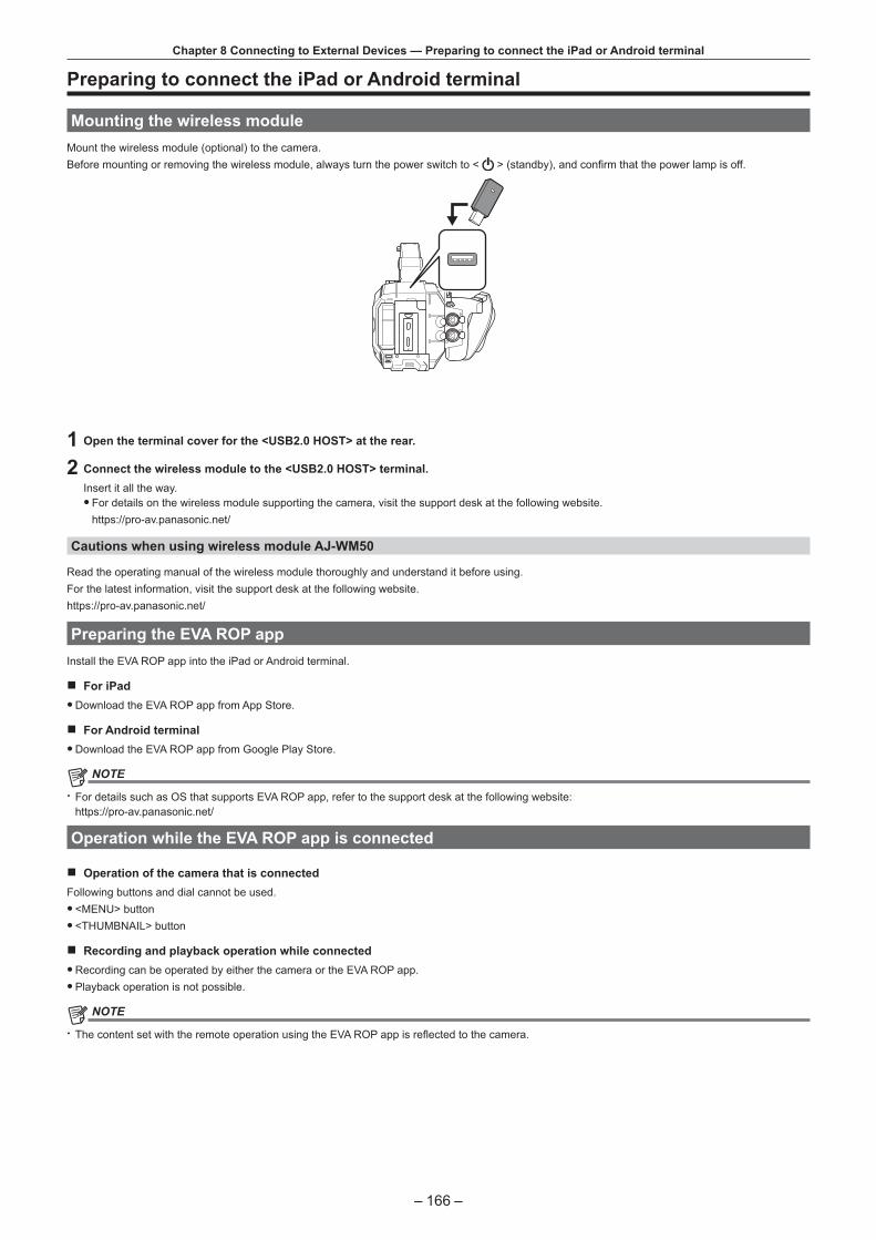
– 166 –
Chapter 8 Connecting to External Devices — Preparing to connect the iPad or Android terminal
Preparing to connect the iPad or Android terminal
Mounting the wireless moduleMount the wireless module (optional) to the camera.Before mounting or removing the wireless module, always turn the power switch to < > (standby), and confirm that the power lamp is off.
1 Open the terminal cover for the <USB2.0 HOST> at the rear.
2 Connect the wireless module to the <USB2.0 HOST> terminal.Insert it all the way.
f For details on the wireless module supporting the camera, visit the support desk at the following website.https://pro-av.panasonic.net/
Cautions when using wireless module AJ-WM50
Read the operating manual of the wireless module thoroughly and understand it before using.For the latest information, visit the support desk at the following website.https://pro-av.panasonic.net/
Preparing the EVA ROP appInstall the EVA ROP app into the iPad or Android terminal.
r For iPad fDownload the EVA ROP app from App Store.
r For Android terminal fDownload the EVA ROP app from Google Play Store.
@@ NOTE
t For details such as OS that supports EVA ROP app, refer to the support desk at the following website:https://pro-av.panasonic.net/
Operation while the EVA ROP app is connected
r Operation of the camera that is connectedFollowing buttons and dial cannot be used.
f <MENU> button f <THUMBNAIL> button
r Recording and playback operation while connected fRecording can be operated by either the camera or the EVA ROP app. fPlayback operation is not possible.
@@ NOTE
t The content set with the remote operation using the EVA ROP app is reflected to the camera.

– 167 –
Chapter 8 Connecting to External Devices — Camera settings
Camera settingsFollowing information of the camera is necessary to connect the iPad or the Android terminal to the camera.
fUser account nameRefer to “Setting the user account name and the password”. fPasswordRefer to “Setting the user account name and the password”. f IP addressRefer to “Connecting the camera and the iPad/Android terminal”.It is not necessary to set the IP address when the [NETWORK SETTINGS] menu → [NETWORK PROPERTY] → [DHCP] → [SERVER] is selected.(Factory setting: [SERVER])
Setting the user account name and the password
1 Select the [NETWORK SETTINGS] menu → [NETWORK FUNC] → [USER ACCOUNT] → [ADD].
2 Enter the user account name and select [Enter]. fEnter the user account name with 31 characters or less.
3 Enter the password and select [Enter]. fEnter the password between 6 characters and 15 characters.
r To enter a characterOperation is the same as entering with a keyboard.
Icon Description of operation[A-a] Switches between upper case and lower case.
Returns to the previous screen. Entered character is not reflected.
Switches the character to symbol/number.
Enters space (blank).
[BS] Deletes the character. Previous character is deleted when the cursor position is empty.
/ Moves the cursor to right or left.
[Enter] Completes the character entry.
Deleting the user account
1 Select the [NETWORK SETTINGS] menu → [NETWORK FUNC] → [USER ACCOUNT] → [DELETE].The list of registered user account is displayed.
2 Select the user account to delete.A confirmation message appears.
3 To delete, select [SET].Returns to the registered user account list screen.
f To not to delete, select .
4 To continue to delete, perform Steps 2 to 3. f To exit from the operation, select the [EXIT] button.

– 168 –
Chapter 8 Connecting to External Devices — Connecting the camera and the iPad/Android terminal
Connecting the camera and the iPad/Android terminalThis is the setting to connect with the iPad or the Android terminal directly or to connect to the wireless access point via wireless LAN.
Direct connection ([DIRECT])This is the setting to connect the camera to the iPad/Android terminal directly.The camera may restart if necessary when the setting is changed.
1 Select the [NETWORK SETTINGS] menu → [NETWORK PROPERTY] → [TYPE] → [DIRECT].
2 From the [NETWORK SETTINGS] menu → [NETWORK PROPERTY], set each item as necessary. f For details of setting, refer to “Setting items in [NETWORK PROPERTY] when set to [DIRECT]”.
3 Select the [NETWORK SETTINGS] menu → [NETWORK SEL] → [WLAN].
4 Select the SSID of the camera from the SSID list in the iPad/Android terminal, and enter the password (encryption key).Display the wireless access point list screen in wireless LAN setting, and select SSID of the camera.
f Factory setting: [AU-EVA1]When the password confirmation screen appears, enter the password (encryption key).
f Factory setting: [01234567890123456789abcdef]
5 Check the network connection.Once connected, is displayed on the screen of the camera.
r Setting items in [NETWORK PROPERTY] when set to [DIRECT]
[SSID] Network name of the camera (SSID)(Factory setting: [AU-EVA1])
[BAND] Setting to switch between two communication method ([2.4GHz] or [5GHz])(Factory setting: [2.4GHz])
[CHANNEL(2.4GHz)] Channel to be used when [BAND] is set to [2.4GHz](Factory setting: [AUTO])
[CHANNEL(5GHz)] Channel to be used when [BAND] is set to [5GHz](Factory setting: [AUTO])
[ENCRYPT KEY] WPA2 encryption key(Factory setting: [01234567890123456789abcdef])
[DHCP] Setting the DHCP function f [OFF]: Does not use the DHCP function. f [CLIENT]: When connecting by setting [TYPE] to [INFRA(SELECT)] or [INFRA(MANUAL)], it is acquired automatically from the DHCP. (Cannot be selected.) f [SERVER]: Enables the DHCP server function of the camera when connecting with [TYPE] set to [DIRECT].
(Factory setting: [SERVER])
[IP ADDRESS] IP address of the camera(Factory setting: [192.168.0.1])
[SUBNET MASK] Subnet mask(Factory setting: [255.255.255.0])
[DEFAULT GATEWAY] Default gateway(Factory setting: [192.168.0.254])
@@ NOTE
t [DHCP] will be set to [SERVER]. t [ENCRYPTION] will be fixed to [WPA2-AES]. t Depending on the used wireless module, some of the items in [BAND], [CHANNEL(2.4GHz)], and [CHANNEL(5GHz)] may not be able to select.
Connecting to the wireless access point ([INFRA(SELECT)]/[INFRA(MANUAL)])This is the setting to connect the camera to a wireless access point.
When connecting by searching the wireless access point (SSID)
1 Select the [NETWORK SETTINGS] menu → [NETWORK PROPERTY] → [TYPE] → [INFRA(SELECT)].
2 From the [NETWORK SETTINGS] menu → [NETWORK PROPERTY], set each item as necessary. f For details of setting, refer to “Setting items in [NETWORK PROPERTY] when set to [INFRA(SELECT)]”.
3 Select the [NETWORK SETTINGS] menu → [NETWORK SEL] → [WLAN].
4 Select the [NETWORK SETTINGS] menu → [NETWORK PROPERTY] → [SSID]. fDisplays SSID of the searched wireless access point.
5 Select SSID, and select [Enter].Setting is completed when the [ENCRYPT KEY] (encryption key, password) is not set.

– 169 –
Chapter 8 Connecting to External Devices — Connecting the camera and the iPad/Android terminal
6 If the [ENCRYPT KEY] is set, enter the password, and select [Enter].
7 Check the network connection.Once connected, is displayed on the screen of the camera.
@@ NOTE
t ENCRYPTION in WEP is not supported.
r Setting items in [NETWORK PROPERTY] when set to [INFRA(SELECT)]
[ENCRYPTION] [WPA-TKIP], [WPA-AES], [WPA2-TKIP], [WPA2-AES], [NONE](Factory setting: [WPA-AES])
[ENCRYPT KEY] WPA2 encryption key(Factory setting: [01234567890123456789abcdef])
[DHCP] Setting the DHCP function f [OFF]: Does not use the DHCP function. f [CLIENT]: Acquire from DHCP when connecting with [TYPE] set to [INFRA(SELECT)] or [INFRA(MANUAL)]. f [SERVER]: When connecting by setting [TYPE] to [DIRECT], enable the DHCP server function of the camera. (Cannot be selected.)
(Factory setting: [SERVER])
[IP ADDRESS] IP address of the camera(Factory setting: [192.168.0.1])
[SUBNET MASK] Subnet mask(Factory setting: [255.255.255.0])
When entering the wireless access point (SSID) manually
1 Select the [NETWORK SETTINGS] menu → [NETWORK PROPERTY] → [TYPE] → [INFRA(MANUAL)].
2 Set each item in the [NETWORK SETTINGS] menu → [NETWORK PROPERTY] as necessary. f For details of setting, refer to “Setting items in [NETWORK PROPERTY] when set to [INFRA(MANUAL)]”.
3 Select the [NETWORK SETTINGS] menu → [NETWORK SEL] → [WLAN].
4 From the [NETWORK SETTINGS] menu → [NETWORK PROPERTY] → [SSID], enter the SSID of the wireless access point to connect.
5 Select SSID, and select [Enter].Setting is completed when the [ENCRYPT KEY] (encryption key, password) is not set.
6 If the [ENCRYPT KEY] is set, enter the password, and select [Enter].
7 Check the network connection.Once connected, is displayed on the screen of the camera.
@@ NOTE
t ENCRYPTION in WEP is not supported.
r Setting items in [NETWORK PROPERTY] when set to [INFRA(MANUAL)]
[ENCRYPTION] [WPA-TKIP], [WPA-AES], [WPA2-TKIP], [WPA2-AES], [NONE](Factory setting: [WPA-AES])
[ENCRYPT KEY] WPA2 encryption key(Factory setting: [01234567890123456789abcdef])
[DHCP] Setting the DHCP function f [OFF]: Does not use the DHCP function. f [CLIENT]: Acquire from DHCP when connecting with [TYPE] set to [INFRA(SELECT)] or [INFRA(MANUAL)]. f [SERVER]: When connecting by setting [TYPE] to [DIRECT], enable the DHCP server function of the camera. (Cannot be selected.)
(Factory setting: [SERVER])
[IP ADDRESS] IP address of the camera(Factory setting: [192.168.0.1])
[SUBNET MASK] Subnet mask(Factory setting: [255.255.255.0])
When connecting from the history
History of connection is saved when connected to a wireless access point. Connection is easily made with the same setting as before when connecting from the history.
1 Select the [NETWORK SETTINGS] menu → [CONNECTION HISTORY] → [SELECT].The connection history is listed with the SSID of the wireless access point.

– 170 –
Chapter 8 Connecting to External Devices — Connecting the camera and the iPad/Android terminal
2 Select the SSID to connect.
3 Check the network connection.Once connected, is displayed on the screen of the camera.
When deleting the history
1 Select the [NETWORK SETTINGS] menu → [CONNECTION HISTORY] → [DELETE].The connection history is listed with the SSID of the wireless access point.
2 Select the SSID to delete.A confirmation message appears.
3 Select [SET].Returns to Step 2.
f To not to delete, select .
4 To continue to delete, perform Steps 2 to 3.To exit from the operation, select the [EXIT] button.
@@ NOTE
t Maximum of 20 histories that were recently used can be saved.

Maintenance of the camera or frequently asked questions are described.
Chapter 9 Notes

– 172 –
Chapter 9 Notes — Frequently asked questions
Frequently asked questions
Power supply
r What is the power supply voltage supported by the supplied AC adaptor? fAC 100 V-240 V
r Can the supplied AC adaptor used while the battery is mounted? f It can be used. Supplying of the power is automatically switched to the AC adaptor side when the power is set to < > (ON) and the AC adaptor is connected while the battery is mounted.The power status display in the LCD monitor will change from the mark to the .
r The camera cannot be operated even when the power is set to < > (ON). fRemove the power supply (the battery or the AC adaptor), and connect it again after approximately one minute. f The operation of the corresponding button or the switch is disabled when the <LOCK> switch on the camera is set to < >. Unlock if necessary.
Battery
r The battery gets exhausted quickly, so is there any way to improve? fCharge the battery sufficiently. f The operating time becomes shorter in low temperature. f If the time is short after sufficient charging, the battery life has expired.
r Can the battery that was used in the previous models used? fVW-VBD58 (optional) can be used.It is recommended to use the following Panasonic genuine batteries. - AG-VBR59 (supplied/optional, 7.28 V, 5900 mAh) - AG-VBR89 (optional, 7.28 V, 8850 mAh) - AG-VBR118 (optional, 7.28 V, 11800 mAh)
r Can the supplied battery be charged with the battery charger AG-B23 (DE-A88) (optional)? f It can perform normal charging. It cannot perform quick charging.
Battery charger
r Can the previous battery charged with the supplied charger? f It can perform normal charging. f To perform quick charging, use the quick charging compatible battery. The camera is compatible to following quick charging compatible batteries. - AG-VBR59 (supplied/optional, 7.28 V, 5900 mAh) - AG-VBR89 (optional, 7.28 V, 8850 mAh) - AG-VBR118 (optional, 7.28 V, 11800 mAh)
SD card
r Operation is not accepted even when an SD card is inserted into the card slot. f The SD card to be used on the camera should always be formatted on the camera.The SD card formatted in a PC cannot be used in the camera.
Shooting
r The shooting stops by itself, and cannot shoot. fWhen the recording format is set to MOV format, use the SDXC memory card. MOV format data cannot be recorded on the SDHC memory card. fUse the SD card with required Speed Class in accordance with the recording bit rate. (page 48)
r Audio cannot be recorded. fAudio cannot be recorded in the following cases. - When the variable frame rate recording function is enabled, and the frame rate is set different from the system frequency - When the interval recording function is enabled
fWhen audio cannot be recorded, is displayed in the HOME screen, and A.REC is displayed in the VIEW screen.
Editing
r Can the camera be connected to a computer (Windows/Mac) via USB? f The camera does not have an USB device terminal, so the camera cannot be connected to a PC via USB. Connect the commercially available SD card reader to a PC, and copy the contents (data) directly from the SD card.

– 173 –
Chapter 9 Notes — Frequently asked questions
Playback
r The clip cannot be played back. f The clip displaying in the thumbnail screen cannot be played back.
is displayed on following clips. - A clip shot with other device, a clip edited by an editing software - Corrupted clip
f is displayed on the clip in the thumbnail mode when the clip has different recording mode (MOV format/AVCHD format), or different system frequency. Change the system frequency or the recording codec.
r The clip cannot be erased. fCancel the protect on the clip. f The clip displaying in the thumbnail screen may not be able to erase.Format the SD card if the clip is unwanted.All the data recorded on the SD will be erased when formatted. Save the necessary data into a PC, etc.
r Can the contents shot with AG-DVX200 or AG-UX180 be played back? f The contents recorded in MOV format/MP4 format cannot be played back. The camera has changed the folder structure of the SD card to maintain the compatibility of the file name with the Panasonic VARICAM series (AU-V35LT1G etc.). f The contents recorded in AVCHD format can be played back. Contents recorded in the format that cannot be recorded with the camera cannot be played back.
Others
r Can the wired remote control used with AG-DVX200 series be used? f The controlling format is different, so it cannot be used.

– 174 –
Chapter 9 Notes — Warning system
Warning systemWhen an error is detected right after the camera is turned on or during the operation, occurrence of error is notified in the HOME screen, VIEW screen, or by the tally lamp. Deal with the error by following the indications.
Cases indicated by error messages
System error
Screen displayDescription Behavior and cause
VIEW screen HOME screen[SYSTEM ERROR] — An error in the standard signal or communication
error has occurred.All the tally lamps and the card access lamps (orange) will flash four times a second, and an alarm is sounded.
f Set the power to < > (standby).
Warning
Screen displayDescription Behavior and cause
VIEW screen HOME screen[LOW BATTERY] — Remaining battery capacity is insufficient. All the tally lamps and the card access lamps
(orange) will flash four times a second, and an alarm is sounded.The power status display becomes , and it will flash once every second in red.
f The power is turned off in approximately five seconds. f Replace with a fully charged battery, or connect the AC adaptor.
[HIGH TEMPERATURE] — Displayed when the internal temperature of the camera has risen above assumed.
All the tally lamps and the card access lamps (orange) will flash four times a second, and an alarm is sounded.
f The power is turned off in approximately five seconds. f Turn on the power again and check recording and playback operations. If the problem persists, consult the dealer.
[REC WARNING] An error of the recording data has occurred during recording, and the recording has stopped.
All the tally lamps and the card access lamps (orange) will flash four times a second, and an alarm is sounded.
f Recording is stopped.
[REC WARNING] It has tried to record exceeding the maximum number of clips during recording.
All the tally lamps and the card access lamps (orange) will flash four times a second, and an alarm is sounded.
f Recording is stopped. f When [DIAGNOSTICS] is selected in the INFO screen, [REC WARNING] [<OVER MAX NUM. OF CLIPS>] is displayed in the warning display area. f Replace the SD card or delete unnecessary clips.
[CARD ERROR <SLOT 1>]/[CARD ERROR <SLOT 2>]
A data error caused by the SD card has occurred during recording or playback.
f When it was recordingAll the tally lamps and the card access lamps (orange) will flash four times a second, and an alarm is sounded.Recording is stopped.After the recording is stopped, the SD card where the error has occurred is write protected. Replace the SD card in the card slot where the error occurred. f When it was playing backPlayback is stopped.
[END](SD card status display)
— The remaining recordable capacity of the SD card has exhausted during recording.
All the tally lamps and the card access lamps (orange) will flash four times a second, and an alarm is sounded.
f Recording is stopped. f Replace the SD card or delete unnecessary clips.
(Once every second, flash in red)
— Battery is almost consumed. All the tally lamps will flash once every second. f The current operation will continue. f Replace with a fully charged battery, or connect the AC adaptor.
SD card remaining recordable capacity display(Flashes once every second during recording)
— The remaining recordable capacity of the SD is getting low.
f Recording will continue. f Replace the SD card as necessary.

– 175 –
Chapter 9 Notes — Warning system
Alert
Screen displayDescription Behavior and cause
VIEW screen HOME screen[SIMUL REC WARNING <SLOT 1>]/[SIMUL REC WARNING <SLOT 2>]
An error has occurred in one of the SD card during simultaneous recording.
A message is displayed for approximately five seconds.
f Recording to the other SD card will continue.
[SIMUL REC WARNING <SLOT 1>]/[SIMUL REC WARNING <SLOT 2>]
It has tried to record exceeding the maximum number of clips to one of the SD card during simultaneous recording.
A message is displayed for approximately five seconds.
f Recording to the other SD card will continue. f When [DIAGNOSTICS] is selected in the INFO screen, [SIMUL REC WARNING] [<OVER MAX NUM. OF CLIPS>] is displayed in the warning display area. f Replace the SD card or delete unnecessary clips.
[FAN STOPPED] The fan has stopped. A message is displayed. f The current operation will continue. f Stop the use immediately when the fan has stopped, and consult the dealer. f If the fan has stopped, temperature of the camera will rise. Therefore, do not use the camera for a long period of time.
[REINSERT OR CHECK CARD <SLOT 1>]/[REINSERT OR CHECK CARD <SLOT 2>]
The card cannot be recognized properly because a recording medium which is not supported has been inserted or there is dirt on the terminal of the card.
A message is displayed for approximately five seconds.
f Check the card that is inserted. f If it is displayed when the SD card is inserted, reinsert the SD card.
[FORMAT ERROR CARD <SLOT 1>]/[FORMAT ERROR CARD <SLOT 2>]
The SD card with management information that is out of specification is inserted.(Include when the system frequency (59.94 Hz system or 50 Hz system) for the AVCHD format in the SD card is different from the setting in the [SYSTEM SETTINGS] menu → [SYSTEM MODE] → [FREQUENCY])
A message is displayed for approximately five seconds.
f Insert an SD card that can be recorded. f The system frequency information for the AVCHD format is confirmed at the time of formatting or at the first recording.
[NOT SDXC CARD <SLOT 1>]/[NOT SDXC CARD <SLOT 2>]
The SDHC memory card that cannot record the MOV format data is inserted when [MAIN CODEC] is set to MOV format.
A message is displayed for approximately five seconds.
f Insert an SDXC memory card.
[INCOMPATIBLE CARD <SLOT 1>]/[INCOMPATIBLE CARD <SLOT 2>]
The SD card that may not be able to record due to slow writing speed is inserted.
A message is displayed for approximately five seconds.
f The current operation will continue. f Use an SD card with sufficient writing speed.
[BACKUP BATT EMPTY] Voltage lowering of the backup battery for internal clock was detected when the power is set to < > (ON).
A message is displayed for approximately five seconds.
f The current operation will continue. f Set the date/time again after charging the built-in battery.

– 176 –
Chapter 9 Notes — Warning system
Message
Screen displayDescription Behavior and cause
VIEW screen HOME screen[CANNOT PLAY.] — This is a clip that cannot be played back.
(When it cannot be played back due to difference of the system frequency, etc.)An error has occurred during playback, and the playback has stopped.
A message is displayed. f Confirm if the system frequency of the clip is the same as the system frequency of the camera. f Check the clip.
[CANNOT DELETE.] — This is a clip that cannot be deleted. A message is displayed. f Match the device and content versions.
[CANNOT RECORD. THE NUMBER OF CLIPS HAS EXCEEDED THE MAXIMUM LIMIT.]
— The number of clips that can be recorded has reached the maximum.
A message is displayed. f Replace the SD card or delete unnecessary clips.
[CARD ERROR. PLEASE REFORMAT.]
— Formatting of the SD card has failed. A message is displayed. f Format it again.
[Repair failed.] — Repairing of the clip that an error has occurred has failed due to disconnection of the power or removing of the SD card during recording.Restoring of the management information has failed.
A message is displayed. f Check the SD card.
[UNABLE TO FORMAT.] — This is an SD card that cannot be formatted. A message is displayed. f Check the SD card.
[CANNOT REPAIR CONTROL INFORMATION DUE TO LOW BATTERY POWER.]
— Management information cannot be restored due to insufficient remaining battery capacity.
A message is displayed. f Replace with a fully charged battery, or connect the AC adaptor.
[CANNOT PROTECT.] — This is a clip that cannot be protected. A message is displayed. f Match the device and content versions.
[THE CLIP IS PROTECTED. PLEASE CANCEL PROTECTION.]
— The clip is protected so it cannot be deleted. A message is displayed. f Cancel the protect on the clip.
[CANNOT DELETE UNTIL TOP MENU IS DELETED. DELETE TOP MENU? (RECORDED DATA WILL NOT BE DELETED)]
— It is trying to delete a clip on the SD card where the top menu is created.
A message is displayed. f Delete the top menu.
[CANNOT RECORD UNTIL TOP MENU IS DELETED. DELETE TOP MENU? (RECORDED DATA WILL NOT BE DELETED)]
— The SD card with top menu created is inserted. A message is displayed. f Delete the top menu.
[THUMBNAIL DATA ERROR IS DETECTED.]
— An error occurred in the thumbnail information of the SD card.
A message is displayed. f Restoring of the management information is performed automatically after this.
[CANNOT RECORD - INCOMPATIBLE CONTROL DATA.]
— Version of the management information of the SD card is not supported.
A message is displayed. f Match the device and content versions.
[CANNOT SET.] — This cannot be set. A message is displayed. f Perform the setting after making it possible to set.
[THIS CLIP CANNOT BE COPIED.]
— The clip cannot be copied. A message is displayed. f Copy the clips other than the corresponding clip.
[CONTROL DATA ERROR HAS BEEN DETECTED. (SD CARD)]
— An error occurred in the management information of the SD card.
A message is displayed. f Restoring of the management information is performed automatically after this.
[COPY FAILED. PLEASE CHECK THE CARD.]
— Copying of the clip has failed due to an error in the SD card.
A message is displayed. f Check the SD card.
[COPY TERMINATION IN PROGRESS DUE TO INSUFFICIENT BATTERY POWER. DO NOT SWITCH OFF.]
— Remaining battery capacity became low while copying the clip.
A message is displayed. f The copy is cancelled. f Replace with a fully charged battery, or connect the AC adaptor.
[COPY TERMINATED DUE TO INSUFFICIENT BATTERY POWER.]
— Copying of a clip is cancelled due to insufficient remaining battery capacity.
A message is displayed. f Replace with a fully charged battery, or connect the AC adaptor.
[CANNOT COPY - THE NUMBER OF CLIPS HAS REACHED MAXIMUM.]
— The number of clips that can be copied has reached the maximum.
A message is displayed. f Replace the SD card or delete unnecessary clips in the copy destination.
[LOW BATTERY. PLEASE CONNECT AC ADAPTOR OR CHANGE BATTERY.]
— It is trying to copy a clip or update the camera firmware while the remaining battery capacity is insufficient.
A message is displayed. f Replace with a fully charged battery, or connect the AC adaptor.
[CANNOT PLAY THIS CLIP ON THIS MODEL.]
— This is a clip that cannot be played back with the camera.
A message is displayed. f Playback on a device that can playback.
[Cannot copy: contains recordings from other devices.]
— The clip recorded in other device cannot be copied. A message is displayed. f Copy the clips other than the corresponding clip.

– 177 –
Chapter 9 Notes — Warning system
Screen displayDescription Behavior and cause
VIEW screen HOME screen[ERROR HAS OCCURRED. TO REPAIR THE CONTROL DATA, PLEASE CONNECT AC ADAPTOR OR CHANGE BATTERY.]
— The remaining battery capacity was low when the restoring of the management information is started.
A message is displayed. f Replace with a fully charged battery, or connect the AC adaptor.
[INVALID] — Operation is disabled. A message is displayed. f Operate after the the operation becomes enabled.
[Cannot record - Playlist capacity is full.]
— It has tried to record on the SD card which the number of playlist that can be recorded has reached the maximum.
A message is displayed. f Replace the SD card or delete unnecessary clips.
[Cannot copy - Playlist capacity is full.]
— It has tried to copied to the SD card which the number of playlist that can be recorded has reached the maximum.
A message is displayed. f Replace the SD card or delete unnecessary clips.
[Exceeds capacity. Please reselect.]
— The remaining recordable capacity of the copy destination SD card is insufficient.
A message is displayed. f Reselect the clip to copy, or secure sufficient remaining recordable capacity in the copy destination SD card.
[Check the destination media.] — An error has occurred in the copy destination SD card while copying.
A message is displayed. f Confirm the copy destination SD card.
[SCENE FILE LOAD FAILED] — Reading of the scene file has failed. A message is displayed. f Check the SD card.
[SCENE FILE WRITE FAILED] — Writing of the scene file has failed. A message is displayed. f Check the SD card.
[DISCONNECT USB CABLE.] — Due to an OS non-compatible error, five minutes has elapsed until the USB service mode connection is established.
A message is displayed. f Confirm if the OS in use is supported by the camera.
[CARD LOCKED.] — It has tried to protect or delete a clip in the locked SD card.It has tried to copy a clip to the locked SD card.
A message is displayed. f Unlock the SD card.
[CANNOT SELECT MORE CLIPS.]
— It has tried to select more than 99 clips. A message is displayed. f Execute the process such as copying by every 99 clips.
[SELECT THE CLIP TO BE DELETED.]
— It has tried to delete a clip without choosing any. A message is displayed. f Select a clip to be deleted.
[SELECT THE CLIPS TO COPY.] — It has tried to copy a clip without choosing any. A message is displayed. f Select a clip to be copied.
[Insert a card in slot 1.] — It has tried to copy without inserting the SD card into the card slot 1.
A message is displayed. f Insert an SD card into the card slot 1.
[Insert a card in slot 2.] — It has tried to copy without inserting the SD card into the card slot 2.
A message is displayed. f Insert an SD card into the card slot 2.
[REINSERT OR CHECK CARD <SLOT 1>]/[REINSERT OR CHECK CARD <SLOT 2>]
— It has tried to copy to an error card. A message is displayed. f Check the SD card.
[CANNOT COPY.] — It has tried to copy a content recorded in a AVCHD format with a different system frequency (59.94 Hz system or 50 Hz system) between the copy source SD card the copy destination SD card.
A message is displayed. f Set the system frequency (59.94 Hz system or 50 Hz system) for the contents in the copy source SD card and the copy destination SD card to be the same. f The system frequency information for the AVCHD format is confirmed at the time of formatting or at the first recording.
[CANNOT RECORD.] — Cannot be recorded. A message is displayed. f Perform recording after making it possible.

– 178 –
Chapter 9 Notes — Recording function that cannot be used simultaneously
Recording function that cannot be used simultaneouslyDepending on the recording function that is set, there are recording functions that cannot be used simultaneously.
fMeaning of the symbols used in the table are as follows. - l: Can be used simultaneously. - —: Cannot be used simultaneously.
Recording function that is setRecording function to additionally set
Pre-recording*1*2*3 Relay recording*3 Simultaneous recording*3
Interval recording*3*4*5*6*7*8
VFR*4*5*6
Pre-recording*1*2*3 l l — —
Relay recording*3 l — — l*9
Simultaneous recording*3 l — l l*9
Interval recording*3*4*5*6*7*8
— — l —
VFR*4*5*6 — l*9 l*9 —
*1 Time code is fixed to free run.*2 The pre-recording is cancelled once when three hours has passed without starting the recording.*3 When the [SYSTEM SETTINGS] menu → [SYSTEM MODE] → [SDI RAW] is set to anything other than [OFF], this cannot be set.*4 Cannot set simultaneously in the following cases.
fWhen recording in AVCHD format*5 Time code is fixed to recording run.*6 When the [SYSTEM SETTINGS] menu → [SYSTEM MODE] → [FREQUENCY] is set to [50.00i]/[59.94i], this cannot be set.*7 The time code is fixed to [NDF].*8 The [OUTPUT SETTINGS] menu → [SDI OUT] → [SDI REC REMOTE] and the [OUTPUT SETTINGS] menu → [HDMI OUT] → [HDMI REC REMOTE] will
not operate.*9 The function will not operate if the [SYSTEM SETTINGS] menu → [SYSTEM MODE] → [SENSOR MODE] is set to [S35 MIX 2.8K] or [4/3 CROP&MIX 2.2K].

– 179 –
Chapter 9 Notes — Updating the camera firmware
Updating the camera firmwareConfirm the firmware version of the camera in the [SYSTEM SETTINGS] menu → [INFORMATION] → [VERSION], and access the most current information regarding firmware in the website described in NOTE, and download the firmware if required.
@@ NOTE
t Update is completed by loading the downloaded file to the camera via the SD card. Insert the SD card that stores the update file into the card slot 1, and select the [SYSTEM SETTINGS] menu → [INFORMATION] → [UPDATE]. For update method, refer to the support desk at the following website:https://pro-av.panasonic.net/
t Always perform update of the firmware with the LCD monitor unit mounted. t When updating the firmware, use the AC adaptor or sufficiently charged battery. t Do not turn off the power while updating the firmware. Rewriting of the firmware may fail and the camera may not be activated.

– 180 –
Chapter 9 Notes — Cleaning and storing
Cleaning and storing
Cleaning the camera body fRemove the battery or disconnect the AC cable from the power outlet before cleaning. fDo not use benzine or thinner to clean the camera. Using benzine or thinner may cause deformation or peeling off of the paint of the camera body. fWipe the camera body with a soft and clean cloth. If there is heavy dirt attached, wipe the camera recorder using a cloth soaked in kitchen detergent diluted with water, and then wipe it with a dry cloth.
Cautions when storing the camera recorderRemove the battery from the camera when storing. Store them in a place where humidity is low and temperature is relatively constant.
fRecommended temperature: 15 °C to 25 °C (59 °F to 77 °F) fRecommended relative humidity: 40% to 60%
r Camera fWrap the camera recorder with a soft cloth so that dust does not get into it.
r Battery f The battery life shortens where the temperature is extremely high or low. fStoring in a place where there is heavy oil smoke or dust may lead to malfunctions due to rust on terminal connectors, etc. fDo not let the battery terminal contact a metal object (such as a necklace or hairpin). Short circuit may occur between terminals and it may lead to heat generation. Touching on a heated part may cause severe burns. fStore the battery with electrically discharged. When storing for a long period of time, it is recommended to charge the battery once a year, and then use up the battery capacity by the camera before storing it again.
r SD card f If you remove it from the camera recorder, be sure to put it in its case. fDo not place it in a place where there is corrosive gas. fDo not place it in a place where temperature gets high, such as in a car or under direct sunlight. fDo not place it in a high humid or dusty place.

This chapter describes the specifications of this product.
Chapter 10 Specification

– 182 –
Chapter 10 Specification — Dimensions
Dimensions
135
mm
(5-5
/16
inch
es)
235
mm
(9-1
/4 in
ches
)
133
mm
(5-1
/4 in
ches
)
196
mm
(7-2
3/32
inch
es)
183 mm (7-7/32 inches)
100 mm (3-15/16 inches) 170 mm (6-11/16 inches)
217 mm (8-17/32 inches)

– 183 –
Chapter 10 Specification — Specifications
Specifications
General
PowerDC e 7.28 V (when battery is used)DC e 12 V (when the AC adaptor is used)Power consumption19 W (when LCD monitor is used)
indicates safety information.
Operating ambient temperature 0 °C - 40 °C (32 °F - 104 °F)
Operating ambient humidity 10% - 80% (relative humidity, no condensation)
Mass Approx. 1.2 k] (2.6 lbs.) (camera body only, excluding the accessories)Approx. 2.05 k] (4.5 lbs.) (including accessories of handle, grip, LCD monitor, LCD monitor hood, microphone holder, microphone holder adaptor, and battery)
Dimensions (W×H×D) Camera body only135 mm×133 mm×170 mm(5-5/16 inches×5-1/4 inches×6-11/16 inches)(excluding protrusion)
Camera unit
Pickup device Super 35 mm, MOS sensor
Number of pixels f Total pixels: Approx. 20.49 million pixels (6340 (H) × 3232 (V)) f Valid pixels: Approx. 17.52 million pixels (5720 (H) × 3016 (V))
Lens mount EF mount
Optical filter f Built-in ND filter, electrical[ND:1.8]/[ND:1.2]/[ND:0.6]/[ND:CLR]
f IR cut filter[ON]/[OFF] by assigning [IR SHOOTING] to the USER button (switched by menu)
Color temperature setting ATW, AWB A, AWB B, 2000 K - 15000 K, −10.0GMg - +10.0GMgUp to 13 items can be registered
Gain setting f [ISO] modeDual native ISO compatible, [200 ISO] to [25600 ISO] f [dB] mode[NORMAL]/[HIGH] gain compatible, −12 dB to 26 dB (2 dB steps)
Shutter speed f When set to [deg]3.0 deg - 357.0 deg (0.5 deg steps)Maximum of 12 items can be registered f When set to [sec]1/24.1 seconds to 1/8000 seconds (for 23.98p)Maximum of 12 items can be registered
Memory card recorder
Recording media f Card slot × 2SDHC memory card (4 GB - 32 GB)SDXC memory card (exceeding 32 GB - 128 GB): UHS-I/UHS-II, UHS Speed Class 3 compatible, video Speed Class V90 compatible
Number of recording pixels 4096×2160 (4K), 3840×2160 (UHD), 2048×1080 (2K), 1920×1080 (FHD), 1280×720 (HD)
Recording codec MOV, AVCHD
System frequency 59.94p, 59.94i, 50p, 50i, 29.97p, 24p, 25p, 23.98p
Recording frame rate (max) f 4K/UHD59.94fps or 50fps f 2K/HD120fps/100fps240fps/200fps (crop mode)
Recording format f MOV: 4:2:0 (10 bits)HEVC LongGOP 200M/HEVC LongGOP 150M f MOV: 4:2:0 (8 bits)420LongGOP 150M/420LongGOP 100M/420LongGOP 50M f MOV: 4:2:2 (10 bits)422LongGOP 150M/422LongGOP 100M/422LongGOP 50M422ALL-I 400M/422ALL-I 200M/422ALL-I 100M f AVCHD: PS/PH/HA/PM

– 184 –
Chapter 10 Specification — Specifications
Recording video signal 4096×2160/59.94p, 50p, 29.97p, 25p, 24p, 23.98p3840×2160/59.94p, 50p, 29.97p, 25p, 23.98p2048×1080/59.94p, 50p, 29.97p, 25p, 24p, 23.98p1920×1080/59.94p, 50p, 29.97p, 25p, 23.98p, 59.94i, 50i1280×720/59.94p, 50p
Recording and playback time When using a 64 GB SDXC memory card f 4096×2160/422ALL-I 400M/29.97p, 25p, 23.98p, 24pApprox. 20 minutes f 2048×1080/422ALL-I 200M/59.94p, 50pApprox. 40 minutes f 4096×2160/420LongGOP 150M/59.94p, 50pApprox. 55 minutes f 2048×1080/420LongGOP 100M/59.94p, 50pApprox. 1 hour 20 minutes f 1920×1080/420LongGOP 50M/29.97p, 25p, 23.98pApprox. 2 hours 40 minutes
Two‑slot function Simultaneous recording, relay recording
Special recording Pre-recording, interval recording
Digital video
Number of quantizing bits f MOV: 4:2:2 (10 bits)/4:2:0 (8 bits)/4:2:0 (10 bits (HEVC)) f AVCHD: 4:2:0 (8 bits)
Video compression format H.264/MPEG-4 AVC High ProfileH.265/MPEG-H HEVC Main10 Profile
Digital audio
Recording audio signal f MOV: 48 kHz/24 bits, 2ch f AVCHD: 48 kHz/16 bits, 2ch
Audio recording format f MOV: LPCM f AVCHD: Dolby AudioTM
Headroom 18 dB/20 dB switchable by menu
Video output
<SDI OUT> terminal f BNC×14K (6G), HD (3G/1.5G): 0.8 V [p-p], 75 Ω f SDI remote control support f Output format (4:2:2 (10 bits) output)4096×2160/3840×2160: 29.97p, 25p, 24p, 23.98p1920×1080: 59.94p, 50p, 59.94i, 50i, 29.97p, 29.97fps, 25p, 25fps, 24p, 24fps, 23.98p, 23.98fps1280×720: 59.94p, 50p f RAW output format (10 bits)5760×3072: 29.97p, 25p, 24p, 23.98p (maximum 30fps/25fps)4096×2160: 59.94p, 50p, 29.97p, 25p, 24p, 23.98p (maximum 60fps/50fps)2048×1080: 59.94p, 50p, 29.97p, 25p, 24p, 23.98p (maximum 240fps/200fps)
<HDMI> terminal f HDMI type A × 1 (VIERA Link not compatible) f HDMI remote control support f Output format (4:2:2 (10 bits) output)4096×2160/3840×2160: 59.94p, 50p, 29.97p, 25p, 24p, 23.98p1920×1080: 59.94p, 50p, 59.94i, 50i, 29.97p, 25p, 24p, 23.98p1280×720: 59.94p, 50p720×480: 59.94p720×576: 50p
Audio input
Built-in microphone Supports stereo microphone

– 185 –
Chapter 10 Specification — Specifications
<AUDIO INPUT 1>/<AUDIO INPUT 2> terminal XLR×2, 3-pinInput high impedance, [LINE]/[MIC] switch by menu
f [LINE]: 4 dBu/0 dBu (selectable menu) f [MIC]: −40 dBu/−50 dBu/−60 dBu (selectable menu), +48 V ON/OFF (switch by menu)
Audio output
<SDI OUT> terminal<HDMI> terminal
LPCM 2ch
Headphone terminal Stereo mini jack × 1
Speaker 20 mm diameter, round ×1
Other input/output
<TC IN/OUT> terminal BNC×1Used as input/output terminal, input/output switch by menu
f Input: 1.0 V - 4.0 V [p-p], 10 kΩ f Output: 2.0 V±0.5 V [p-p], low impedance
<LCD> terminal 40-pin (for connecting LCD monitor)
<REMOTE> terminal 2.5 mm diameter super mini jack × 1, for connecting grip
<USB2.0 HOST> terminal Type A connector, 4-pin (5 V, 0.5 A), for attaching the wireless module (optional)
<DC IN 12V> terminal DC12 V, EIAJ type 4
Monitor
LCD monitor 3.5-type LCD monitor(Approx 1.15 million dots), touch panel supportCan be changed to mirror shooting display with the <MIRROR> switch
AC adaptor
Power sourceAC d 100 V - 240 V, 50 Hz/60 Hz, 1.2 APower outputDC e 12 V, 3.0 A
indicates safety information.
Operating ambient temperature 0 °C - 40 °C (32 °F - 104 °F)
Operating ambient humidity 10% - 90% (relative humidity, no condensation)
Mass Approx. 225 ] (0.496 lbs.)
Dimensions (W×H×D) 115 mm×37 mm×57 mm (4-1/2 inches×1-7/16 inches×2-1/4 inches) (excluding the DC cable section)
Battery charger (AG-BRD50)
Input voltageDC e 12 V, 3.0 AOutput voltageDC e 8.4 V, 4.0 A
indicates safety information.
Charging current Maximum 4,000 mA
Operating ambient humidity 10% - 80% (relative humidity, no condensation)
Mass Approx. 230 ] (0.507 lbs.)
Dimensions (W×H×D) 130 mm×48 mm×107 mm (5-1/8 inches×1-7/8 inches×4-3/16 inches)
Battery pack (AG-VBR59)
Voltage/capacityDC e 7.28 V/5900 mAh 43 Wh
indicates safety information.

Index
– 186 –
Index
AAC adaptor
Attaching 34Audio input 140
Audio device 140Built-in microphone 140Confirming setting 142Direct volume control function 141External microphone 140Level adjustment 140Monitor 141Switching 140
BBattery
Charging 31Mounting 33Removing 33
Built-in battery 46
CCenter marker 134Clip
Copy 147Deleting 148Playback 150Protect 148Restoring 149
Clock 47Color bars 139
DDate and time 47Digital zoom function 138
EElectronic image stabilization function 137Error message 174External microphone
Mounting 42
FFocus assist function 135Frame marker 135
GGrip
Mounting 36
HHandle
Mounting 35Removing 35
Headphones 164High-speed shooting 130HOME screen 64, 66
IImage quality adjustment
[BLACK] 124[CHROMA] 128[COLOR CORRECTION] 129[DETAIL] 127[EI] 123[GAMMA] 124[HLG KNEE] 127[KNEE] 126[MATRIX] 128[SKIN DETAIL] 128[WHITE] 123[WHITE CLIP] 127
INFO screen 69Interval recording 132IR shooting 133
LLCD monitor
Status display 158LCD monitor unit
Mounting 39Removing 39
LensMounting 43
Level gauge 139
MMenu
[AUDIO SETTINGS] 90[CAMERA SETTINGS] 80Configuration 70Display 71[FILE] 103Initialization 73[NETWORK SETTINGS] 104Operation 72[OPTION] 106[OUTPUT SETTINGS] 93[REC SETTINGS] 88[SCENE FILE SETTINGS] 84[SYSTEM SETTINGS] 74[THUMBNAIL] 74
Monitor 164
NNetwork
Wireless LAN 166
OOne-push auto focus function 135Output format
<HDMI> terminal 156<SDI OUT> terminal 155
PPower
How to turn off 45How to turn on 45
Pre-recording 131
RRelay recording 131Remote operation 165Resume play 152
SSafety zone marker 134Scene files 115Screen display 62SD card 48
Data structure 51Format 50Insert 49Recording time 50Remove 49Status 48Write protection 48
Setup file 116Shooting 119Shoulder strap 41Simultaneous recording 132Specifications 183Still picture recording function 153Switching screen 63
TTally lamp 60Thumbnail 144Thumbnail screen 144Time code 55

Index
– 187 –
External preset 56Supply to external 57
Time data 54Tripod 44TV 164
UUpdate 179Usage Restriction 178User bits 54USER buttons
Assignment 58Confirm 59
VVIEW screen 158
WWarning system 174Waveform monitor function 138Wireless LAN
Direct connection 168Wireless access point 168
Wireless module 166
ZZebra patterns 134

Information on Disposal in other Countries outside the European UnionEU These symbols are only valid in the European Union. If you wish to discard these items, please contact
your local authorities or dealer and ask for the correct method of disposal.
Web Site: http://www.panasonic.com
©Panasonic Corporation 2017