european technical assessment eta 14/0363 of 14/11/2014
TRANSCRIPT
ETA 14/0363 of 14/11/2014 — page 1 of 15
LABORATÓRIO NACIONAL DE ENGENHARIA CIVIL, I. P.Av. do Brasil 101 • 1700-066 LISBOA • PORTUGALtel.: (351) 21 844 30 00 • fax: (351) 21 844 30 11e-mail: [email protected] • www.lnec.pt
European Technical Assessment ETA 14/0363of 14/11/2014
English translation prepared by LNEC; original version in Portuguese language ISSN 2183-3362
Trade name of the construction productDesignação comercial do produto de construção
DIERATHERM
Product family to which the construction product belongsFamília de produtos a que o produto de construção pertence
External Thermal Insulation Composite System with rendering on expanded polystyrene for use as external insulation of building walls Sistema Compósito de Isolamento Térmico pelo Exterior com revestimento aplicado sobre isolante térmico de poliestireno expandido moldado destinado ao isolamento exterior de paredes de edifícios
ManufacturerFabricante
DIERA - Fábrica de Revestimentos, Colas e Tintas, LdaRua D. Marcos da Cruz, 1223 - Ap. 30374450-731 Leça da Palmeira Portugal
Manufacturing plant(s)Instalações de fabrico
Rua D. Marcos da Cruz, 1223 - Ap. 30374450-731 Leça da PalmeiraPortugal
This European Technical Assessment containsEsta Avaliação Técnica Europeia contém
15 pages, including 3 annexes which form an integral part of this assessment15 páginas, incluindo 3 anexos que fazem parte desta avaliação
This European Technical Assessment is issued in accordance with Regulation (EU) No. 305/2011, on the basis ofA presente Avaliação Técnica Europeia é emitida ao abrigo do Regulamento (UE) n.º 305/2011, com base no
Guideline for European Technical Approval (ETAG) No. 004, edition 2013, used as European Assessment Document (EAD)Guia de Aprovação Técnica Europeia (ETAG) n.º 004, edição de 2013, utilizado como Documento de Avaliação Europeu (DAE)

ETA 14/0363 of 14/11/2014 — page 2 of 15
1. Technical description of the product
The External Thermal Insulation Composite System (from now on, referred to as ETICS) DIERATHERM is designed and installed in accordance with the manufacturer’s design and installation instructions, deposited with LNEC1.
DIERATHERM is a bonded system with supplementary mechanical fixings used primarily to provide stability until the adhesive has dried and increase the adherence of the system reducing the risk of detachment.
The ETICS comprises the components identified in Table 1, which are factory produced by the manufacturer or a supplier.
It is made up on site from these components. The manufacturer is ultimately responsible for the ETICS.
2. Specification of the intended use in accordance with the applicable European Assessment Document (EAD)
This ETICS is intended to be used as external thermal insulation for building walls. The walls are made of masonry (bricks or blocks) or concrete (cast on site or as prefabricated panels) with a reaction to fire classification A1 to A2-s2,d0 according to EN 13501-1 or A1 according to the EC decision 96/603/EC as amended. The ETICS is designed to give the wall to which is applied satisfactory thermal insulation.
The ETICS is made of non load-bearing construction elements. It does not contribute directly to the stability of the wall on which is installed, but it can contribute to its durability by providing enhanced protection from the effect of weathering. The minimum thermal resistance of the ETICS shall be ≥ 1,0 m2K/W.
This ETICS can be used on new or existing (retrofit) vertical walls. It can also be used on horizontal or inclined surfaces which are not exposed to precipitation.
The ETICS is not intended to ensure the air tightness of the building structure.
Design and installation of ETICS should take into account the principles laid down in chapter 7 of ETAG 004 and shall be done in accordance with national instructions. This ETA covers the application of bonded ETICS where the concrete for testing of bond strength is representative for masonry or concrete. For bonded applications onto other substrates (e.g. organic paints or ceramic tiles), testing on the job site is necessary.
The provisions made in this ETA are based on an assumed working life of at least 25 years, provided that the conditions laid down for the installation, appropriate use, maintenance and repair are met.
The indications given on the working life cannot be interpreted as a guarantee given by the producer, but are to be regarded only as a means for choosing the right product in relation to the expected economically reasonable working life of the works.
Installation
The ETICS is installed on site. It is the responsibility of the manufacturer to guarantee that the information about design and installation of this ETICS is effectively communicated to the concerned people. This information can be given using reproductions of the respective parts of this European Technical Assessment. Besides, all the data concerning the execution shall be clearly indicated on the packaging and/or the enclosed instruction sheets using one or several illustrations.
The wall on which the ETICS is applied shall be sufficiently stable and airtight. Its stiffness shall be big enough to ensure that the ETICS is not subjected to deformations, which could lead to damage. The requirements given in ETAG 004, chapter 7, have to be considered.
1 The technical documentation of this European Technical Assessment is deposited with Laboratório Nacional de Engenharia Civil (LNEC) and, as far as relevant for the tasks of the notified body (bodies) involved in the assessment and verification of constancy of performance procedure, is handed over to the notified body (bodies).
Translations of this European Technical Assessment in other languages shall fully correspond to the original issued document and should be identified as such.
Communication of this European Technical Assessment, including transmission by electronic means, shall be in full. However, partial reproduction may be made, with the written consent of the issuing Technical Assessment Body. Any partial reproduction has to be identified as such.
This European Technical Assessment may be withdrawn by the issuing Technical Assessment Body, in particular pursuant to information by the Commission according to Article 25, Paragraph 3, of Regulation (EU) No. 305/2011.

ETA14/0363 of 14/11/2014 — page 3 of 15
TABLE 1Definition of the components
Components Trade name Description1 Coverage (kg/m2)
Thickness(mm)
Insulation product DIERA TH EPS 100Expanded polystyrene (EPS)Panels with 1000 mm × 500 mm and bulk density of 21 kg/m3, with CE marking
– 40 to 80
AdhesiveDIERA TH THERM
BRANCO
Mortar in powder based on mixed binders, composed by white cement CEM II/A L 52.5 N (br), siliceous sand, water retention agent (non toxic), natural fibres and synthetic resins. With CE marking
4 to 5 –
Base coatDIERA TH THERM
BRANCO
Mortar in powder based on mixed binders, composed by white cement CEM II/A L 52.5 N (br), siliceous sand, water retention agent (non toxic), natural fibres and synthetic resins. With CE marking
with standard glass fibre
4 to 5 2 to 2.5
with reinforcedglass fibre
7 to 8 3.5 to 4.5
Finishing coats
F1
DIERA TH ARGTEC
Mortar composed by white cement CEMII/A-L 52.5 N (br), white washed siliceous sand, lime, micronized calcium carbonate, water retention agents (non toxic), cellulose fibres, synthetic additives and acrylic resins
2.20 to 3.50
1.5 to 2
DISOLCRYLKey coat based on silicate watery dispersion of acrylic resins (with particles of nano and micro dimensions), opacifiers pigments, fillers and additives
0.10 to 0.20
DIERATINCRYLWatery paint based on acrylic resins, opacifier pigments, fillers and additives
0.20 to 0.50
F2
PRIMÁRIO RV PLASCRYL
Key coat based on a watery dispersion of acrylic resins, inorganic mineral fillers, quartz sand, pigments and specific additives
0.10 to 0.12
1 to 1.5
DIERA RVPLASCRYL M/F
Decorative thick finishing coat, composed by a watery dispersion of acrylic resins, inorganic mineral fillers, pigments and specific additive
1.50 to 2.50
Glass fibre meshes
DIERA THREDE FIBRA 167
Standard mesh (glass fibre mesh with mesh size 5 mm × 4 mm) (in accordance with Agrément Certificate DH 918 by LNEC)
– –
DIERA THREDE FIBRA 275
Reinforced mesh (glass fibre mesh with mesh size 6 mm × 6 mm) (in accordance with Agrément Certificate DH 918 by LNEC)
– –
Anchors (supplementary mechanical fixings)
DIERA THCAVILHAS
Description in accordance with ETA 08/01722
Remain under the ETA holder responsibility– –
Ancillary materialsDescription in accordance with clause 3.2.2.5 of ETAG 004Remain under the ETA holder responsability
1 See clause 3.2 for further description, characteristics and performances of components.2 ETA based on ETAG 014 – Guideline for European Technical Approval of plastic anchors for fixing of external thermal insulation composite systems with
rendering, edition 2011.
Design
The user shall comply with the national regulations particularly concerning fire and wind load resistance. Only the components described in clause 1 with characteristics according to clause 3 of this ETA can be used for this ETICS.
The works including the details (such as connections and joints) shall be designed in order to avoid water penetration behind the system. To bond the ETICS, the minimum surface area and the method of bonding shall comply with the characteristics of the ETICS (see 3.2.4 of this ETA) as well as the national regulations. In any case, the minimum surface shall be at least 25 %.

ETA 14/0363 of 14/11/2014 — page 4 of 15
Execution
The recognition and preparation of the substrate as well as the generalities about the execution of the ETICS shall be carried out in compliance with:
• chapter 7 of the ETAG 004, with imperative removal of any existing paint finish or renders which may difficult the bond resistance of the system;
• national regulations.
The particularities in execution linked to the method of bonding and the application of the rendering system shall be handled in accordance with manufacturer prescriptions. In particular it is suitable to comply with the quantities of rendering applied, the thickness regularity and the drying periods between layers.
Use, maintenance and repair of the works
It is accepted that the finishing coats shall normally be maintained in order to fully preserve the system’s performance. Maintenance will include at least:
• the repair of localized damaged areas due to accidents;• the application of various products or paints, possibly after washing or surface preparation.
Necessary repairs should be done rapidly. It is important to be able to carry out maintenance as far as possible using readily available products and equipment, without spoiling appearance.
3. Performance of the product and references to the methods used for its assessment
3.1 General The identification tests and the assessment for the intended use of this ETICS according to the Essential Requirements were carried out in compliance with the ETA Guideline no. 004: External Thermal Insulation Composite Systems with Rendering – edition February 2013 (called ETAG 004, in this ETA).
3.2 ETICS characteristics
3.2.1 Mechanical resistance and stability (BWR 1)
Not relevant.
3.2.2 Safety in case of fire (BWR 2)
a) Reaction to fire
The reaction to fire was tested according to EN 13823:2002 and EN 11925-2:2002 and classified according to EN 13501-1:2007+A1:2009.
The ETICS meets the requirements of class B-s1,d0 and B-s2,d0 according to EN 13501-1:2007+A1:2009, respectively for finishing coats F1 (DIERA TH ARGTEC + DISOLCRYL + DIERATINCRYL) and F2 (PRIMÁRIO RV PLASCRYL + DIERA RV PLASCRYL M/F).
Note: In some Member States, the ETICS classification according to EN 13501-1:2007+A1:2009 might not be sufficient for the use in façades. An additional assessment of ETICS according to national provisions (e.g., on the basis of a large scale test) might be necessary to comply with Member State regulations.
3.2.3 Hygiene, health and environment (BWR 3)
a) Water absorption
The results of the water absorption test of the base coat (system with and without finishing), presented in Table 2, verify the following condition:
− water absorption after 1 hour < 1 kg/m2.
The system is therefore judged to have satisfactory performance concerning water absorption, independently of the finishing coat.
b) Hygrothermal behaviour
The ETICS has been assessed on a rig including the thermal insulation and all finishing coats.
During heat-rain and heat-cold cycles, none of the following defects occurs during testing:
• blistering or peeling of the finishing;
• failure or cracking associated with joints between insulation product boards or profiles fitted with the system;
• detachment of render;
• cracking allowing water penetration to the insulation layer.
The ETICS is therefore assessed as resistant to hygrothermal cycles.

ETA14/0363 of 14/11/2014 — page 5 of 15
c) Freeze / thaw behaviour
The water absorption of the system configurations composed by the base coat and the finishing coat F1 (DIERA TH ARGTEC + DISOLCRYL + DIERATINCRYL) and by the base coat and the finishing coat F2 (PRIMÁRIO RV PLASCRYL + DIERA RV PLASCRYL M/F) are respectively higher and less than 0.5 kg/m2 after 24 hours.
Therefore, the classification concerning freeze-thaw resistance is the following:
• Configuration “EPS + base coat + standard mesh + finishing coat F2” – no test but freeze-thaw resistant according to the capillarity test result;
• Any other configuration – NPD.
TABLE 2Water absorption (capillarity test)
System specimensWater absorption
after 1 h(kg/m2)
Water absorptionafter 24 h
(kg/m2)
EPS + base coat + standard mesh 0.33 0.61
EPS + base coat + standard mesh + finishing coat F1 (DIERA TH ARGTEC + DISOLCRYL + DIERATINCRYL)
0.13 0.61
EPS + base coat + standard mesh + finishing coat F2 (PRIMÁRIO RV PLASCRYL + DIERA RV PLASCRYL M/F)
0.09 0.33
d) Impact resistance
The resistance to hard body impact (3 and 10 Joules) tests carried out on samples of systems compositions lead to the use categories presented in Table 3.
TABLE 3Impact resistance to hard body impacts
System Use categories1
EPS + base coat + standard mesh III
EPS + base coat + standard mesh + reinforced mesh II
EPS + base coat + standard mesh + finishing coat F1 (DIERA TH ARGTEC + DISOLCRYL+ DIERATINCRYL)
III
EPS + base coat + standard mesh + reinforced mesh + finishing coat F1 (DIERA TH ARGTEC + DISOLCRYL + DIERATINCRYL)
II
EPS + base coat + standard mesh + finishing coat F2 (PRIMÁRIO RV PLASCRYL + DIERA RV PLASCRYL M/F)
II
EPS + base coat + standard mesh + reinforced mesh + finishing coat F2 (PRIMÁRIO RV PLASCRYL + DIERA RV PLASCRYL M/F)
II
1 Use categories: Category I – zones readily accessible at ground level to the public and vulnerable to hard body impacts but not subjected to abnormally rough use; Category II – zones liable to impacts from thrown or kicked objects, but in public locations where the height of the system will limit the size of the
impact, or at lower levels where access to the building is primarily to those with some incentive to exercise care; Category III – zones not likely to be damaged by normal impacts caused by people or by thrown or kicked objects.

ETA 14/0363 of 14/11/2014 — page 6 of 15
e) Water vapour permeability
Table 4 presents the resistance to water vapour diffusion of the rendering system (base coat and finishing coat) for the two system configurations, expressed by the equivalent air thickness. In both cases, values don’t exceed 2.0 m.
TABLE 4Equivalent air thickness
System specimensEquivalent air thickness
(m)
Base coat + standard mesh + finishing coat F1 (DIERA TH ARGTEC + DISOLCRYL + DIERATINCRYL)
0.61
Base coat + standard mesh + finishing coat F2 (PRIMÁRIO RV PLASCRYL + DIERA RV PLASCRYL M/F)
0.86
f) Dangerous substances
This system complies with the provisions of Guidance Paper H2. A declaration of conformity in this respect was made by the manufacturer.
In addition to the specific clauses relating to dangerous substances contained in this ETA, there may be other requirements applicable to the ETICS falling within its scope (e.g. transposed European legislation and national laws, regulations and administrative provisions). In order to meet the provisions of Regulation (EU) No. 305/11, these requirements need also to be complied with, when and where apply.
3.2.4 Safety on use (BWR 4)
a) Bond strength
– Base coat onto EPS board
Tests were performed on the system applied on the rig, after hygrothermal cycles. The results are summarized in Table 5.
In all cases, bond strength values are higher than 0.08 MPa and the failure occurred in the insulation board (cohesion failure).
TABLE 5Bond strength between base coat and insulation product
System (rig)1 Bond strength (after ageing)(MPa / Failure pattern)2
EPS + base coat + standard mesh 0.22 / FP: C
EPS + base coat + standard mesh + reinforced mesh 0.20 / FP: C
EPS + base coat + standard mesh + finishing coat F1 (DIERA TH ARGTEC + DISOLCRYL + DIERATINCRYL)
0.24 / FP: C
EPS + base coat + standard mesh + reinforced mesh + finishing coat F1 (DIERA TH ARGTEC + DISOLCRYL + DIERATINCRYL)
0.20 / FP: C
EPS + base coat + standard mesh + finishing coat F2 (PRIMÁRIO RV PLASCRYL + DIERA RV PLASCRYL M/F)
0.20 / FP: C
EPS + base coat + standard mesh + reinforced mesh + finishing coat F2 (PRIMÁRIO RV PLASCRYL + DIERA RV PLASCRYL M/F)
0.21 / FP: C
1 Rig – system applied on brick masonry with tested dimensions of 3 m x 2 m. The system was subjected to hygrothermal cycles before the adhesion tests.
2 Failure pattern: FP:C – cohesion failure (failure in the insulation product).
2 Guidance Document H, A harmonized approach related to dangerous subtances under the Construction Products Directive.

ETA14/0363 of 14/11/2014 — page 7 of 15
−Adhesive onto EPS board
Tests were performed on samples of EPS insulation boards faced with adhesive. The results are summarized in Table 6. In all cases, the results are within the limits defined by ETAG 004.
TABLE 6Bond strength between adhesive and insulation product
Specimen
Bond strength (MPa / Failure pattern)1
Initial state
After conditioning
48 h immersion in water+ 2 h 23 °C/50% RH
48 h immersion in water + 7 days 23 °C/50% RH
EPS + adhesive 0.12 / FP:C 0.10 / FP:A 0.15 / FP:C
1 Failure pattern: FP:A – adhesion failure (failure between adhesive-insulation product) and FP:C – cohesion failure (failure in the insulation product).
−Adhesive onto concrete
Tests were performed on samples of concrete boards faced with adhesive product. The results are summarized in Table 7. In all cases, the results are within the limits defined by ETAG 004.
TABLE 7Bond strength between adhesive and substrate (concrete)
Specimen
Bond strength (MPa / Failure pattern)1
Initial state
After conditioning
48 h immersion in water+ 2 h 23 °C/50% RH
48 h immersion in water + 7 days 23 °C/50% RH
Adhesive + substrate (concrete)
0.92 / FP:B 0.54 / FP:A 0.68 / FP:B
1 Failure pattern: FP:A – adhesion failure (failure between adhesive and substrate) and FP:B – cohesion failure (failure in the adhesive).
The minimal bonded surface S is calculated as follows:
S (%) = [0.03 * 100] / Bwhere:
B minimum mean failure resistance of the adhesive to the insulation product in dry conditions expressed in MPa (0.12 MPa);
0.03 MPa corresponds to the minimum requirement.
The minimum bonded surface S is therefore 25%.
The bonding surface of 25% verifies the minimum requirement.
b) Wind load resistance
No performance concerning the wind load resistance has been investigated.
3.2.5 Protection against noise (BWR 5)
No performance concerning the protection against noise has been investigated.
3.2.6 Energy economy and heat retention (BWR 6)
a) Thermal resistance
The additional thermal resistance RETICS provided by the ETICS to the substrate wall is calculated in accordance with EN ISO 6946:2007 from the nominal value of the insulation product’s thermal resistance RD given accompanied to the CE marking and from the thermal resistance of the rendering system Rrender which is about 0.02 m2.K/W:
RETICS = RD + Rrender
Thermal bridges caused by mechanical fixing devices influence the thermal transmittance of the entire wall and shall be taken into account.

ETA 14/0363 of 14/11/2014 — page 8 of 15
The corrected thermal transmittance of the entire wall including ETICS and thermal bridges is calculated using the following expression:
Uc = U + χp.n
where:Uc corrected thermal transmittance of the entire wall including ETICS and thermal bridges (W/(m².K));
U thermal transmittance of the entire wall including ETICS without thermal bridges (W/(m².K));
n number of anchors (through insulation product) per m²;
χp point thermal transmittance value of an anchor (W/K). See EOTA Technical Report no. 025. If not specified in the anchor’s ETA, the following values apply:
= 0.002 W/K for anchors with a stainless steel screw with the head covered by plastic material and for anchors with an air gap at the head of the screw (χp.n negligible for n < 20);
= negligible for anchors with plastic nails (reinforced or not with glass fibres).
The term χp.n has only to be taken into account if it is greater than 0.04 W/(m².K).
The thermal transmittance of the entire wall including ETICS without thermal bridges is determined as follows:
U = 1 / (Ri + Rrender + Rsubstrate + Rse + Rsi)
where:Ri thermal resistance of the insulation product (see CE marking in reference to EPS EN 13163:2008) in m².K/W;
Rrender thermal resistance of the render (about 0.02 m².K)/W);
Rsubstrate thermal resistance of the substrate (concrete, brick,…) in m².K/W;
Rse external surface resistance in m².K/W;
Rsi internal surface resistance in m².K/W.
3.2.7 Sustainable use of natural resources (BWR 7)
No performance determinated.
3.2.8 Aspects of durability and serviceability
a) Bond strength after ageing
Results of the tests for determining the bond strength between the base coat and the insulation product presented in Table 5 show that in all cases the failure occurred in the EPS board (cohesion failure).
3.3 Component characteristics3.3.1 General
Detailed information on the chemical composition and other identifying characteristics of the components, following Annex C of ETAG 004, has been deposited with LNEC.
Further information can be observed from the product data sheets, which are part of the Technical Documentation for this ETA.
3.3.2 Insulation product
Factory-prefabricated boards, made of expanded polystyrene (EPS), having the description, characteristics and performances (as minimum) defined in Table 8 (EN 13163:2012).
3.3.3 Render
– Render strip tensile resistance
Fatigue tests were performed on specimens to determine the rupture stress of the reinforced render. The results are presented in Table 9.

ETA14/0363 of 14/11/2014 — page 9 of 15
TABLE 8Characteristics of insulation panels
Component Trade name Characteristics Declared values and classes
Insulationproduct
DIERA THEPS 100
Reaction to fire(EN 13501-1:2007+A1:2009)
Euroclass EDensity (EN 1602:1997):
21 ± 1 kg/m3
Thickness: 40 to 80 mm
Thermal conductivity 0.036 (W/m.K)
Classes of dimensional tolerances (EN 13163:2012)
Thickness Class T(1): ± 1 mm
Length Class L(2): ± 2 mm
Width Class W(1): ± 1 mm
Squareness Class S(1): ± 1 mm/m
Flatness Class P(3): ± 3 mm
Compressive strength (EN 13163:2012) 100 kPa
Flexural strength (EN 13163:2012) 150
Dimensional stability under laboratory condition (EN 13163:2012)
≤ 1.0 %
Water absorption (partial immersion) (NP EN 1609:1998)
0.04 ± 0.01 kg/m2
Water vapor diffusion resistance factor (EN 12086:1997)
39 ± 3
Tensile strength perpendicular to the faces in dry conditions (EN 1607:1998)
242 ± 10 kPa
Shear strength and shear modulus of elasticity (NP EN 12090:1997)
Shear strength: 130 ± 10 kPaShear modulus of elasticity:
2300 ± 100 kPa
TABLE 9Results of render strip tensile test
System specimen Characteristics Test results
Base coat + standard mesh
Tensile strength (N/mm) 21
Tensile strength while the first crack is formed (N/mm) 5.2
Crack width at relative elongation NPD
3.3.4 Glass fibre meshes
The characteristics of the glass fibre meshes are presented in Table 10.
3.3.5 Anchors
Anchors for expanded polystyrene panels act as supplementary fixing if required. They are covered by ETA 08/0172, according to ETAG 014 – Plastic anchors for fixing external thermal insulation composite systems with rendering, edition 2011 (see Table 1).
Their main characteristics and design data are presented in Table 11.

ETA 14/0363 of 14/11/2014 — page 10 of 15
TABLE 10Results of meshes tensile test
Component Trade name Characteristics Tests results
Standard meshDIERA TH
REDE FIBRA 167
Tensile strength after accelerated artificial ageing (N/mm) 20 (≥ 20)
Relative residual resistance: % (after ageing) of the strength in the as delivered state
61 (> 50)
Mass per surface unit (g/m2) 160 (± 5 %)
Mesh dimensions (mm × mm) 5 × 4 (± 5 %)
Reinforced meshDIERA THREDE 275
Tensile strength after accelerated artificial ageing (N/mm) 38 (> 20)
Relative residual resistance: % (after ageing) of the strength in the as delivered state
67 (> 50)
Mass per surface unit (g/m2) 330 (± 5 %)
Mesh dimensions (mm × mm) 6 × 6 (± 5 %)
TABLE 11Description and characteristics of anchors
Component Trade name CharacteristicsDeclared values and design data
AnchorsDIERA TH CAVILHAS
Anchor typeSee dimensional characteristics in Table 2
of Annex 3 of ETA 08/0172
MaterialsAnchor (plastic expansion sleeve):
polypropylene Nail: glass fibre reinforced polyamide
Resistance to tension loads (kN) 0.30 – 0.75 (see ETA 08/0172)
Displacement for the maximum dimensioning load, when applied on concrete (mm)
0.1
Displacement for the maximum dimensioning load, when applied on masonry (mm)
0.3
Spacing (mm) ≥ 100
Edge distance (mm) ≥ 100
Thickness of the substrate (mm) ≥ 100
4 Assessment and verification of constancy of performance (hereinafter AVCP) system applied, with reference to its legal base
According to the decision 97/556/EC of the European Commission of 14 July 19973 as amended by the decision 2001/596/EC4 of 8 January of 2001, and considering the class B for the reaction to fire of the ETICS and that no stage in the production process has been identified that could result in an improvement of the reaction to fire characteristic, the system of assessment and verification of constancy of performance (see Annex V, as amended by Commission Delegated Regulation no. 568/2014 of 18 February 2014, and article 65 paragraph 2 of Regulation (EU) no. 305/2011) given in Table 12 applies.
3 Official Journal of the European Communities L229/14 of 20.08.1997.
4 Official Journal of the European Communities L229/33 of 02.08.2001.

ETA14/0363 of 14/11/2014 — page 11 of 15
TABLE 12System of assessment and verification of constancy of performance
Product Intended uses Levels or classes System
DIERATHERM External thermal insulation composite system with rendering for use on building walls
Any 2+
This system of assessment and verification of constancy of performance +2 is defined as follows:
System 2+: Declaration of the performance of the essential characteristics of the construction product by the manufacturer on the basis of:
a) Tasks for the manufacturer:
(1) factory production control; (2) testing of samples taken at the factory in accordance with a prescribed test plan.
b) Tasks for the notified factory production control certification body:
(3) decision on the issuing, restriction, suspension or withdrawal of the certificate of conformity of the factory production control on the basis of the outcome of the following assessments and verifications carried out by that body:
– initial inspection of the manufacturing plant and of factory production control; – continuous surveillance, assessment and evaluation of factory production control.
5 Technical details necessary for the implementation of the AVCP system, as provided for in the applicable EAD
5.1 GeneralThe ETA is issued on the basis of agreed data/information, deposited with LNEC, which identifies the product that has been assessed and judged. It is the manufacturer’s responsibility to make sure that all those who use the kit are appropriately informed of the specific conditions laid down in this ETA, including its annexes.
Changes to the ETICS or the components or their production process should be notified to LNEC before the changes are introduced. LNEC will decide whether or not such changes affect the ETA and if so whether further assessment or alterations to the ETA shall be necessary.
5.2 Tasks for the manufacturer
Factory production control
The manufacturer shall exercise permanent internal control of production. All the elements, requirements and provisions adopted by the manufacturer shall be documented in a systematic manner in the form of written policies and procedures, including records of results performed.
This production control system shall ensure that the product is in conformity with this ETA.
The manufacturer may only use components stated in the technical documentation of this ETA. The incoming raw materials are subjected to verifications by the manufacturer before acceptance.
For the components of the ETICS which the manufacturer does not manufacture by himself, he shall make sure that the factory production control carried out by the other manufacturers gives the guarantee of the components compliance with the ETA.
The factory production control shall be in accordance with the Control Plan5 , which is part of the Technical Documentation of this ETA. The control plan has been agreed between the manufacturer and the LNEC and is laid down in the context of the factory production control system operated by the manufacturer and deposited within LNEC. The results of factory production control shall be recorded and evaluated in accordance with the provisions of the control plan.
Other tasks for the manufacturer
The manufacturer shall, on the basis of a contract, involve a body (bodies) which is (are) notified for the tasks referred to in section 4 in the field of ETICS in order to undertake the actions laid down in this clause. For this purpose, the control plan shall be handed over by the manufacturer to the notified body (bodies) involved.
For assessing the ETICS and the components the results of the tests performed as part of the assessment for the ETA shall be used unless there are changes in the production line or plant. In such cases the necessary testing has to be agreed with LNEC.
The declaration of performance of the ETICS to be drawn up by the manufacturer following the issuing of this ETA shall include its
5 The control plan is a confidential part of this European Technical Assessment and is only handed over to the notified body or bodies involved in the procedure of assessment and verification of constancy of performance. See section 5.3.
ETA 14/0363 of 14/11/2014 — page 12 of 15
reference number and issuing date.
Changes to the ETICS or the components or their production process should be notified to LNEC before the changes are introduced. LNEC will decide whether or not such changes affect the ETA and if so whether further assessment or alterations to the ETA shall be necessary.
The declaration of performance of the ETICS to be drawn up by the manufacturer following the issuing of this ETA shall include its reference number and issuing date.
Changes to the ETICS or the components or their production process should be notified to LNEC before the changes are introduced. LNEC will decide whether or not such changes affect the ETA and if so whether further assessment or alterations to the ETA shall be necessary.
5.3 Tasks for the notified body (bodies)Within the scope of the initial inspection of factory and of factory production control, the notified body (bodies) shall ascertain that, in accordance with the Control Plan, the factory (in particular the employees and the equipment) and the factory production control are suitable to ensure continuous and orderly manufacturing of the components according to the specifications mentioned in this ETA.
Within the scope of continuous surveillance, assessment and evaluation of factory production control, the notified body (bodies) shall visit the factory at least once a year for surveillance. It has to be verified that the factory production control is maintained in suitable conditions.
These tasks shall be performed in accordance with the provisions laid down in the control plan.
The notified body (bodies) shall retain the essential points of its (their) actions referred to above and state the results obtained and conclusions drawn in a written report.
The notified body involved by the manufacturer shall issue a certificate of conformity of the factory production control stating the conformity with the provisions of this ETA.
In cases where the provisions of the ETA and its control plan are no longer fulfilled, the notified certification body shall withdraw the certificate of conformity and inform LNEC without delay.
Issued in Lisbon on 14/11/2014
By
Laboratório Nacional de Engenharia Civil (LNEC)
The Board of Directors
Carlos Pina
President
ETA14/0363 of 14/11/2014 — page 13 of 15
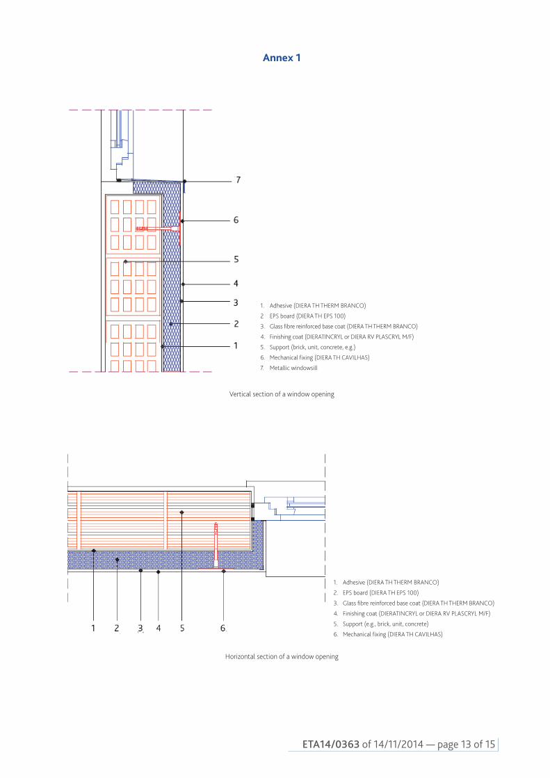
1. Adhesive (DIERA TH THERM BRANCO)
2 EPS board (DIERA TH EPS 100)
3. Glass fibre reinforced base coat (DIERA TH THERM BRANCO)
4. Finishing coat (DIERATINCRYL or DIERA RV PLASCRYL M/F)
5. Support (brick, unit, concrete, e.g.)
6. Mechanical fixing (DIERA TH CAVILHAS)
7. Metallic windowsill
Vertical section of a window opening
1. Adhesive (DIERA TH THERM BRANCO)
2. EPS board (DIERA TH EPS 100)
3. Glass fibre reinforced base coat (DIERA TH THERM BRANCO)
4. Finishing coat (DIERATINCRYL or DIERA RV PLASCRYL M/F)
5. Support (e.g., brick, unit, concrete)
6. Mechanical fixing (DIERA TH CAVILHAS)
Horizontal section of a window opening
Annex 1

ETA 14/0363 of 14/11/2014 — page 14 of 15
1. Adhesive (DIERA TH THERM BRANCO)
2. EPS board (DIERA TH EPS 100)
3. Glass fibre reinforced base coat (DIERA TH THERM BRANCO)
4. Finishing coat (DIERATINCRYL or DIERA RV PLASCRYL M/F)
5. Corner profile (DIERA TH PVC ESQ)
6. Mechanical fixing (DIERA TH CAVILHAS)
7. Support (e.g., brick, unit, concrete)
Horizontal section of corner with profile
Annex 2

ETA14/0363 of 14/11/2014 — page 15 of 15
Annex 3
1. Adhesive (DIERA TH THERM BRANCO)
2. EPS board (DIERA TH EPS 100)
3. Glass fibre reinforced base coat (DIERA TH THERM BRANCO)
4. Finishing coat (DIERATINCRYL or DIERA RV PLASCRYL M/F)
5. Mechanical fixing (DIERA TH CAVILHAS)
6. Support (brick, unit, concrete, e.g.)
7. End profile (DIERA TH ALM)
8. System of waterproofing and protection from ground
Vertical section of ETICS start

Div
isão
de
Div
ulga
ção
Cie
ntífi
ca e
Téc
nica
- LN
EC
Descriptors: Wall coating / External wall / Expanded polystyrene / Thermal insulation / Composite material / / Europe
Descritores: Revestimento de paredes / Parede exterior / Poliestireno expandido / Isolamento térmico / / Material compósito / Europa
CDU 693.695:699.86(4) 692.23:699.86(4)ISSN 2183-3362