european technical assessment eta-11/0027 of...
TRANSCRIPT

ETA-Danmark A/S Göteborg Plads 1 DK-2150 Nordhavn Tel. +45 72 24 59 00 Fax +45 72 24 59 04 Internet www.etadanmark.dk
Authorised and notified according to Article 29 of the Regulation (EU) No 305/2011 of the European Parliament and of the Council of 9 March 2011
MEMBER OF EOTA
European Technical Assessment ETA-11/0027 of 26/10/2016
I General Part Technical Assessment Body issuing the ETA and designated according to Article 29 of the Regulation (EU) No 305/2011: ETA-Danmark A/S Trade name of the construction product:
fischer Power-Fast screws and fischer construction screws
Product family to which the above construction product belongs:
Screws for use in timber constructions
Manufacturer: fischerwerke GmbH & Co. KG
Klaus-Fischer-Str. 1 72178 Waldachtal GERMANY
Manufacturing plant: fischerwerke
This European Technical Assessment contains:
37 pages including 3 annexes which form an integral part of the document
This European Technical Assessment is issued in accordance with Regulation (EU) No 305/2011, on the basis of:
European Assessment document (EAD) no. EAD 130118-00-0603 “Screws for timber constructions”
This version replaces: The previous ETA with the same number issued on
2013-06-26 and expiry on 2018-06-26
Page 2 of 37 of European Technical Assessment no. ETA-11/0027, issued on 2016-10-26
Translations of this European Technical Assessment in other languages shall fully correspond to the original issued document and should be identified as such.
Communication of this European Technical Assessment, including transmission by electronic means, shall be in full (excepted the confidential Annex(es) referred to above). However, partial reproduction may be made, with the written consent of the issuing Technical Assessment Body. Any partial reproduction has to be identified as such.
Page 3 of 37 of European Technical Assessment no. ETA-11/0027, issued on 2016-10-26
II SPECIFIC PART OF THE EUROPEAN TECHNICAL ASSESSMENT
1 Technical description of product and
intended use Technical description of the product “fischer Power-Fast” and “fischer construction screws” are self-tapping screws to be used in timber structures. “fischer Power-Fast” screws shall be threaded over a part or over the full length. “fischer construction screws” shall be threaded over a part of the length. The screws shall be produced from carbon steel wire for nominal diameters of 3,0 mm to 12,0 mm and from stainless steel wire for nominal diameters of 3,0 mm to 8,0 mm. The material specification of the stainless steel screws is deposited with ETA-Danmark. Where corrosion protection is required, the material or coating shall be declared in accordance with the relevant specification given in Annex A of EN 14592.
Geometry and Material The nominal diameter (outer thread diameter), d, shall not be less than 3,0 mm and shall not be greater than 12,0 mm. The overall length, L, of screws shall not be less than 20 mm and shall not be greater than 600 mm. Other dimensions are given in Annex A1 to Annex A18. The ratio of inner thread diameter to outer thread diameter di/d ranges from 0,59 to 0,69. The screws are threaded over a minimum length g of 4,0∙d (i.e. g > 4,0∙d). The lead p (distance between two adjacent thread flanks) ranges from 0,50∙d to 0,67∙d. No breaking of screws shall be observed at a bend angle, , of less than (45/d0,7 + 20) degrees. The material specification of the of the stainless steel screws is deposited with ETA-Danmark. 2 Specification of the intended use in
accordance with the applicable EAD The screws are used for connections in load bearing timber structures between members of solid timber (softwood and hardwood). Furthermore, all kinds of processed timber products (all softwood and hardwood as well), such as glued laminated timber, cross-laminated timber, laminated veneer lumber, similar glued members, wood-based panels or steel.
Furthermore “fischer Power-Fast” screws with diameter of 6 mm, 8 mm, 10 mm and 12 mm may also be used for the fixing of heat insulation on rafters and on vertical facades. Steel plates and wood-based panels except solid wood panels and cross laminated timber shall only be located on the side of the screw head. The following wood-based panels may be used: - Plywood according to EN 636 or ETA - Particleboard according to EN 312 or ETA - Oriented Strand Board, Type OSB/3 and OSB/4
according to EN 300 or ETA - Fibreboard according to EN 622-2 and 622-3 or
ETA (minimum density 650 kg/m³) - Cement bonded particleboard according to ETA - Solid wood panels according to EN 13353 and EN
13986, and cross laminated timber according to ETA
- Laminated Veneer Lumber according to EN 14374 or ETA
- Engineered wood products according to ETA if the ETA of the product includes provisions for the use of self-tapping screws, the provisions of the ETA of the engineered wood product apply
The screws shall be screwed into softwood without pre-drilling or after pre-drilling with a diameter not larger than the inner thread diameter for the length of the threaded part and with a maximum of the smooth shank diameter for the length of the smooth shank. The screws shall be driven into hardwood after pre-drilling with a suitable diameter according to section 3.11.
The screws are intended to be used in timber connections for which requirements for mechanical resistance and stability and safety in use in the sense of the Basic Works Requirements 1 and 4 of Regulation 305/2011 shall be fulfilled.
Form and dimensions of washers are given in Annex A19. Washers must be made of steel.
The design of the connections shall be based on the characteristic load-carrying capacities of the screws. The design capacities shall be derived from the characteristic capacities in accordance with Eurocode 5 or an appropriate national code (e.g. DIN 1052:2008-12). Regarding environmental conditions, national provisions at the building site shall apply.
The screws are intended for use for connections subject to static or quasi static loading.
The zinc-coated screws are for use in timber structures subject to the dry, internal conditions defined by the
Page 4 of 37 of European Technical Assessment no. ETA-11/0027, issued on 2016-10-26
service classes 1 and 2 of EN 1995-1-1:2008 (Eurocode 5). The screws made of stainless steel meet the requirements of Eurocode 5 (EN 1995-1-1:2008), for use in structures subject to the wet conditions defined as service class 3. The scope of the screws regarding resistance to corrosion shall be defined according to national provisions that apply at the installation site considering environmental conditions. The provisions made in this European Technical Assessment are based on an assumed intended working life of the screws of 50 years. The indications given on the working life cannot be interpreted as a guarantee given by the producer or Assessment Body, but are to be regarded only as a means for choosing the right products in relation to the expected economically reasonable working life of the works.
Page 5 of 37 of European Technical Assessment no. ETA-11/0027, issued on 2016-10-26
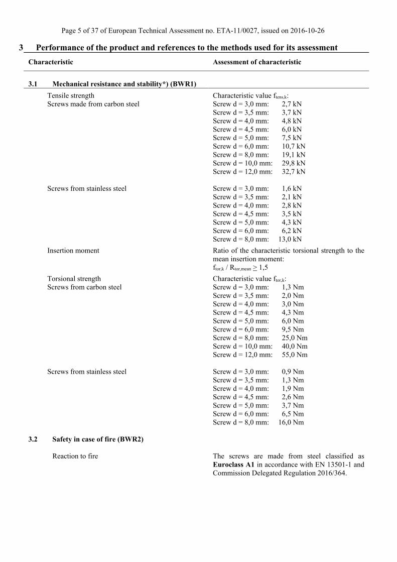
3 Performance of the product and references to the methods used for its assessment
Characteristic Assessment of characteristic
3.1 Mechanical resistance and stability*) (BWR1)
Tensile strength Screws made from carbon steel Screws from stainless steel
Characteristic value ftens,k: Screw d = 3,0 mm: 2,7 kN Screw d = 3,5 mm: 3,7 kN Screw d = 4,0 mm: 4,8 kN Screw d = 4,5 mm: 6,0 kN Screw d = 5,0 mm: 7,5 kN Screw d = 6,0 mm: 10,7 kN Screw d = 8,0 mm: 19,1 kN Screw d = 10,0 mm: 29,8 kN Screw d = 12,0 mm: 32,7 kN Screw d = 3,0 mm: 1,6 kN Screw d = 3,5 mm: 2,1 kN Screw d = 4,0 mm: 2,8 kN Screw d = 4,5 mm: 3,5 kN Screw d = 5,0 mm: 4,3 kN Screw d = 6,0 mm: 6,2 kN Screw d = 8,0 mm: 13,0 kN
Insertion moment Ratio of the characteristic torsional strength to the mean insertion moment: ftor,k / Rtor,mean > 1,5
Torsional strength Screws from carbon steel Screws from stainless steel
Characteristic value ftor,k: Screw d = 3,0 mm: 1,3 Nm Screw d = 3,5 mm: 2,0 Nm Screw d = 4,0 mm: 3,0 Nm Screw d = 4,5 mm: 4,3 Nm Screw d = 5,0 mm: 6,0 Nm Screw d = 6,0 mm: 9,5 Nm Screw d = 8,0 mm: 25,0 Nm Screw d = 10,0 mm: 40,0 Nm Screw d = 12,0 mm: 55,0 Nm Screw d = 3,0 mm: 0,9 Nm Screw d = 3,5 mm: 1,3 Nm Screw d = 4,0 mm: 1,9 Nm Screw d = 4,5 mm: 2,6 Nm Screw d = 5,0 mm: 3,7 Nm Screw d = 6,0 mm: 6,5 Nm Screw d = 8,0 mm: 16,0 Nm
3.2 Safety in case of fire (BWR2)
Reaction to fire
The screws are made from steel classified as Euroclass A1 in accordance with EN 13501-1 and Commission Delegated Regulation 2016/364.

Page 6 of 37 of European Technical Assessment no. ETA-11/0027, issued on 2016-10-26
Characteristic Assessment of characteristic
3.3 Hygiene, health and the environment (BWR3)
Influence on air quality
The product does not contain/release dangerous substances specified in TR 034, dated October 2015 **)
3.7 Sustainable use of natural resources (BR7)
No Performance Assessed
3.8 General aspects related to the performance of the product
The screws have been assessed as having satisfactory durability and serviceability when used in timber structures using the timber species described in Eurocode 5 and subject to the conditions defined by service classes 1, 2 and 3
Identification
See Annex A
*) See additional information in section 3.9 – 3.12. **) In addition to the specific clauses relating to dangerous substances contained in this European technical Assessment, there may be other requirements applicable to the products falling within its scope (e.g. transposed European legislation and national laws, regulations and administrative provisions). In order to meet the provisions of the Construction Products Regulation, these requirements need also to be complied with, when and where they apply.
Page 7 of 37 of European Technical Assessment no. ETA-11/0027, issued on 2016-10-26
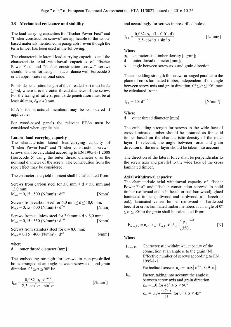
3.9 Mechanical resistance and stability The load-carrying capacities for “fischer Power-Fast” and “fischer construction screws” are applicable to the wood-based materials mentioned in paragraph 1 even though the term timber has been used in the following.
The characteristic lateral load-carrying capacities and the characteristic axial withdrawal capacities of ”fischer Power-Fast” and “fischer construction screws” screws should be used for designs in accordance with Eurocode 5 or an appropriate national code.
Pointside penetration length of the threaded part must be ef > 4∙d, where d is the outer thread diameter of the screw. For the fixing of rafters, point side penetration must be at least 40 mm, ef > 40 mm.
ETA’s for structural members may be considered if applicable.
For wood-based panels the relevant ETAs must be considered where applicable. Lateral load-carrying capacity The characteristic lateral load-carrying capacity of “fischer Power-Fast” and “fischer construction screws” screws shall be calculated according to EN 1995-1-1:2008 (Eurocode 5) using the outer thread diameter d as the nominal diameter of the screw. The contribution from the rope effect may be considered.
The characteristic yield moment shall be calculated from:
Screws from carbon steel for 3,0 mm < d < 5,0 mm and 12,0 mm: My,k = 0,15 ∙ 500 (N/mm²) ∙ d2,6 [Nmm]
Screws from carbon steel for 6,0 mm < d < 10,0 mm: My,k = 0,15 ∙ 600 (N/mm²) ∙ d2,6 [Nmm]
Screws from stainless steel for 3,0 mm < d < 6,0 mm: My,k = 0,15 ∙ 350 (N/mm²) ∙ d2,6 [Nmm]
Screws from stainless steel for d = 8,0 mm: My,k = 0,15 ∙ 400 (N/mm²) ∙ d2,6 [Nmm] where d outer thread diameter [mm] The embedding strength for screws in non-pre-drilled holes arranged at an angle between screw axis and grain direction, 0° ≤ ≤ 90° is:
0,3k
h,k 2 2
0,082 df
2,5 cos sin
[N/mm²]
and accordingly for screws in pre-drilled holes:
kh,k 2 2
0,082 (1 0,01 d)f
2,5 cos sin
[N/mm²]
Where k characteristic timber density [kg/m³]; d outer thread diameter [mm]; angle between screw axis and grain direction. The embedding strength for screws arranged parallel to the plane of cross laminated timber, independent of the angle between screw axis and grain direction, 0° ≤ ≤ 90°, may be calculated from:
0,5h,kf 20 d [N/mm²]
Where d outer thread diameter [mm] The embedding strength for screws in the wide face of cross laminated timber should be assumed as for solid timber based on the characteristic density of the outer layer. If relevant, the angle between force and grain direction of the outer layer should be taken into account. The direction of the lateral force shall be perpendicular to the screw axis and parallel to the wide face of the cross laminated timber. Axial withdrawal capacity The characteristic axial withdrawal capacity of „fischer Power-Fast” and “fischer construction screws” in solid timber (softwood and ash, beech or oak hardwood), glued laminated timber (softwood and hardwood, ash, beech or oak), laminated veneer lumber (softwood or hardwood beech) or cross-laminated timber members at an angle of 0° < < 90° to the grain shall be calculated from:
0,8
kax, ,Rk ef ax ax,k efF n k f d
350
[N]
Where
Fax,,RK Characteristic withdrawal capacity of the connection at an angle to the grain [N]
nef Effective number of screws according to EN 1995-1-1
For inclined screws: 0,9efn max n ; 0,9 n
kax Factor, taking into account the angle between screw axis and grain direction kax = 1,0 for 45° ≤ < 90°
kax = 0,7
0,345
for 0° ≤ < 45°

Page 8 of 37 of European Technical Assessment no. ETA-11/0027, issued on 2016-10-26
fax,k Characteristic withdrawal parameter [N/mm²] screw d = 3,0 mm: fax,k = 13,8 N/mm² screw d = 3,5 mm: fax,k = 13,4 N/mm² screw d = 4,0 mm: fax,k = 13,0 N/mm² screw d = 4,5 mm: fax,k = 12,6 N/mm² screw d = 5,0 mm: fax,k = 12,2 N/mm² screw d = 6,0 mm: fax,k = 11,6 N/mm² screw d ≥ 8,0 mm: fax,k = 10,0 N/mm²
d Outer thread diameter [mm] ef Point side penetration length of the threaded
part according to EN 1995-1-1:2008 [mm] Angle between grain and screw axis [°] k Characteristic density [kg/m³], for hardwoods
the assumed characteristic density shall not exceed 730 kg/m³
For screws arranged under an angle between screw axis and grain direction of less than 90°, the minimum threaded penetration length is: ef ≥ min (4∙d/sin ; 20∙d) For screws penetrating more than one layer of cross laminated timber, the different layers may be taken into account proportionally. The axial withdrawal capacity is limited by the head pull-through capacity and the tensile strength of the screw. For axially loaded screws in tension, where the external force is parallel to the screw axes, the rules in EN 1995-1-1, 8.7.2 (8) should be applied. For inclined screws in timber-to-timber or steel-to-timber shear connections, where the screws are arranged under an angle 30° ≤ ≤ 60° between the shear plane and the screw axis, the effective number of screws nef should be determined as follows: For one row of n screws parallel to the load, the load-carrying capacity should be calculated using the effective number of fasteners nef, where
0,9efn max n ; 0,9 n
and n is the number of inclined screws in a row. If crossed pairs of screws are used in timber-to-timber connections, n is the number of crossed pairs of screws in a row. Note: For inclined screws as fasteners in mechanically
jointed beams or columns or for the fixing of thermal insulation material, nef = n.
Head pull-through capacity The characteristic head pull-through capacity of “fischer Power-Fast” and “fischer construction screws” shall be calculated according to EN 1995-1-1:2008 from:
0,8
2 kax, ,Rk ef head,k hF n f d
350
[N]
where: Fax,,Rk characteristic head pull-through capacity of
the connection at an angle > 30° to the grain [N]
nef effective number of screws according to EN 1995-1-1
For inclined screws: 0,9efn max n ; 0,9 n
(see axial withdrawal capacity) fhead,k characteristic head pull-through parameter
[N/mm²] dh diameter of the screw head [mm] k characteristic density [kg/m³], for wood-
based panels k = 380 kg/m³
Characteristic head pull-through parameter for screws with head diameter ≤ 21 mm in connections with timber and with wood-based panels with thicknesses above 20 mm: fhead,k = 12 N/mm²
Characteristic head pull-through parameter for screws with head diameter 21 mm < dh ≤ 35 mm in connections with timber and with wood-based panels with thicknesses above 20 mm: fhead,k = 10 N/mm²
Characteristic head pull-through parameter for screws in connections with wood-based panels with thicknesses between 12 mm and 20 mm: fhead,k = 8 N/mm²
Screws in connections with wood-based panels with a thickness below 12 mm (minimum thickness of the wood based panels of 1,2∙d with d as outer thread diameter): fhead,k = 8 N/mm² limited to Fax,Rk = 400 N
The head diameter dh shall be greater than 1,8∙ds, where ds is the smooth shank or the wire diameter. Otherwise the characteristic head pull-through capacity Fax,,Rk = 0.
Outer diameter of washers dh > 35 mm shall not be considered.
The minimum thickness of wood-based panels according to the clause 3.9 must be observed.
In steel-to-timber connections the head pull-through capacity is not decisive.
Page 9 of 37 of European Technical Assessment no. ETA-11/0027, issued on 2016-10-26
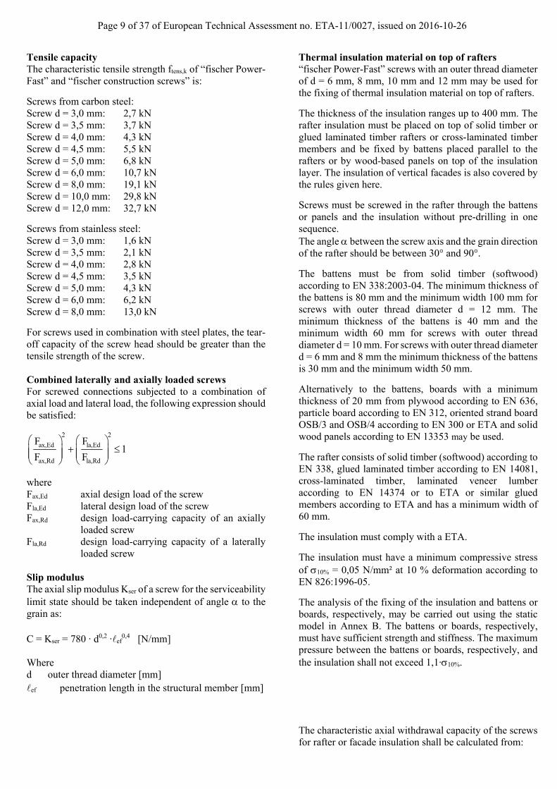
Tensile capacity The characteristic tensile strength ftens,k of “fischer Power-Fast” and “fischer construction screws” is:
Screws from carbon steel: Screw d = 3,0 mm: 2,7 kN Screw d = 3,5 mm: 3,7 kN Screw d = 4,0 mm: 4,3 kN Screw d = 4,5 mm: 5,5 kN Screw d = 5,0 mm: 6,8 kN Screw d = 6,0 mm: 10,7 kN Screw d = 8,0 mm: 19,1 kN Screw d = 10,0 mm: 29,8 kN Screw d = 12,0 mm: 32,7 kN
Screws from stainless steel: Screw d = 3,0 mm: 1,6 kN Screw d = 3,5 mm: 2,1 kN Screw d = 4,0 mm: 2,8 kN Screw d = 4,5 mm: 3,5 kN Screw d = 5,0 mm: 4,3 kN Screw d = 6,0 mm: 6,2 kN Screw d = 8,0 mm: 13,0 kN
For screws used in combination with steel plates, the tear-off capacity of the screw head should be greater than the tensile strength of the screw. Combined laterally and axially loaded screws For screwed connections subjected to a combination of axial load and lateral load, the following expression should be satisfied:
2 2
ax,Ed la,Ed
ax,Rd la,Rd
F F1
F F
where Fax,Ed axial design load of the screw Fla,Ed lateral design load of the screw Fax,Rd design load-carrying capacity of an axially
loaded screw Fla,Rd design load-carrying capacity of a laterally
loaded screw Slip modulus The axial slip modulus Kser of a screw for the serviceability limit state should be taken independent of angle to the grain as: C = Kser = 780 ∙ d0,2 ∙ef
0,4 [N/mm] Where d outer thread diameter [mm] ef penetration length in the structural member [mm]
Thermal insulation material on top of rafters “fischer Power-Fast” screws with an outer thread diameter of d = 6 mm, 8 mm, 10 mm and 12 mm may be used for the fixing of thermal insulation material on top of rafters.
The thickness of the insulation ranges up to 400 mm. The rafter insulation must be placed on top of solid timber or glued laminated timber rafters or cross-laminated timber members and be fixed by battens placed parallel to the rafters or by wood-based panels on top of the insulation layer. The insulation of vertical facades is also covered by the rules given here.
Screws must be screwed in the rafter through the battens or panels and the insulation without pre-drilling in one sequence. The angle between the screw axis and the grain direction of the rafter should be between 30° and 90°.
The battens must be from solid timber (softwood) according to EN 338:2003-04. The minimum thickness of the battens is 80 mm and the minimum width 100 mm for screws with outer thread diameter d = 12 mm. The minimum thickness of the battens is 40 mm and the minimum width 60 mm for screws with outer thread diameter d = 10 mm. For screws with outer thread diameter d = 6 mm and 8 mm the minimum thickness of the battens is 30 mm and the minimum width 50 mm.
Alternatively to the battens, boards with a minimum thickness of 20 mm from plywood according to EN 636, particle board according to EN 312, oriented strand board OSB/3 and OSB/4 according to EN 300 or ETA and solid wood panels according to EN 13353 may be used.
The rafter consists of solid timber (softwood) according to EN 338, glued laminated timber according to EN 14081, cross-laminated timber, laminated veneer lumber according to EN 14374 or to ETA or similar glued members according to ETA and has a minimum width of 60 mm.
The insulation must comply with a ETA.
The insulation must have a minimum compressive stress of 10% = 0,05 N/mm² at 10 % deformation according to EN 826:1996-05.
The analysis of the fixing of the insulation and battens or boards, respectively, may be carried out using the static model in Annex B. The battens or boards, respectively, must have sufficient strength and stiffness. The maximum pressure between the battens or boards, respectively, and the insulation shall not exceed 1,1∙10%.
The characteristic axial withdrawal capacity of the screws for rafter or facade insulation shall be calculated from:

Page 10 of 37 of European Technical Assessment no. ETA-11/0027, issued on 2016-10-26
, ,
∗ , ∗ ∗ ∗ ∗ ∗,
, ∗ ∗,
,
[N]
where Fax,,Rk Characteristic withdrawal capacity of the
connection at an angle to the grain [N] kax Factor, taking into account the angle
between screw axis and grain direction kax = 1,0 for 45° ≤ < 90°
kax = 0,7
0,345
for 0° ≤ < 45°
fax,k Characteristic withdrawal parameter [N/mm²]
d Outer thread diameter [mm] ef Point side penetration length of the threaded
part according to EN 1995-1-1:2008 [mm] Angle between grain and screw axis ( >
30°) k1 min {1; 220/tHI} k2 min {1; 10%/0,12} tHI Thickness of the thermal insulation [mm] 10% Compressive stress of the thermal insulation
under 10 % deformation [N/mm²] 10% ≥ 0,05 N/mm²
fhead,k Characteristic head pull-through parameter [N/mm²]
dh Outer diameter of the screw head [mm] k Characteristic density [kg/m³] ftens,k Characteristic tensile capacity of the screw
[N] Friction forces shall not be considered for the design of the characteristic axial withdrawal capacity of the screws. The anchorage of wind suction forces as well as the bending stresses of the battens or the boards, respectively, shall be considered in design. Additional screws perpendicular to the grain of the rafter (angle = 90°) may be arranged if necessary. Screws for the anchorage of rafter insulation shall be arranged according to Annex B. The maximum screw spacing is eS = 1,75 m. 3.10 Aspects related to the performance of the product 3.10.1 Corrosion protection in service class 1, 2 and 3. The fischer Power-Fast and fischer construction screws are produced from carbon wire. Screws made from carbon steel are electrogalvanised and yellow or blue chromate. The mean thickness of the zinc coating is 5µm. The material specification of the stainless steel screws is deposited with ETA-Danmark.
3.11 General aspects related to the intended use of the product The screws are manufactured in accordance with the provisions of the European Technical Assessment using the automated manufacturing process and laid down in the technical documentation.
The installation shall be carried out in accordance with Eurocode 5 or an appropriate national code unless otherwise is defined in the following. Instructions from fischerwerke GmbH & Co. KG should be considered for installation.
The screws are used for connections in load bearing timber structures between members of solid timber (softwood and hardwood), glued laminated timber (softwood and hardwood), cross-laminated timber (minimum diameter d = 6,0 mm, softwood and hardwood)), laminated veneer lumber (softwood and hardwood), similar glued members (softwood and hardwood), wood-based panels or steel members. The screws may be used for connections in load bearing timber structures with structural members according to an associated ETA, if according to the ETA of the structural member a connection in load bearing timber structures with screws according to an ETA is allowed. Furthermore, the screws with diameters between 6 mm and 12 mm may also be used for the fixing of insulation on top of rafters or at vertical facades. A minimum of two screws should be used for connections in load bearing timber structures. The minimum penetration depth in structural members made of solid, glued or cross-laminated timber is 4∙d. Wood-based panels and steel plates should only be arranged on the side of the screw head. The minimum thickness of wood-based panels should be 1,2∙d. Furthermore, the minimum thickness for following wood-based panels should be: Plywood, Fibreboards: 6 mm Particleboards, OSB, Cement Particleboards: 8 mm Solid wood panels: 12 mm For structural members according to ETA’s the terms of the ETA’s must be considered. If screws with an outer thread diameter d > 8 mm are used in load bearing timber structures, the structural solid or glued laminated timber, laminated veneer lumber and similar glued members must be from spruce, pine or fir. This does not apply for screws in pre-drilled holes.
Page 11 of 37 of European Technical Assessment no. ETA-11/0027, issued on 2016-10-26
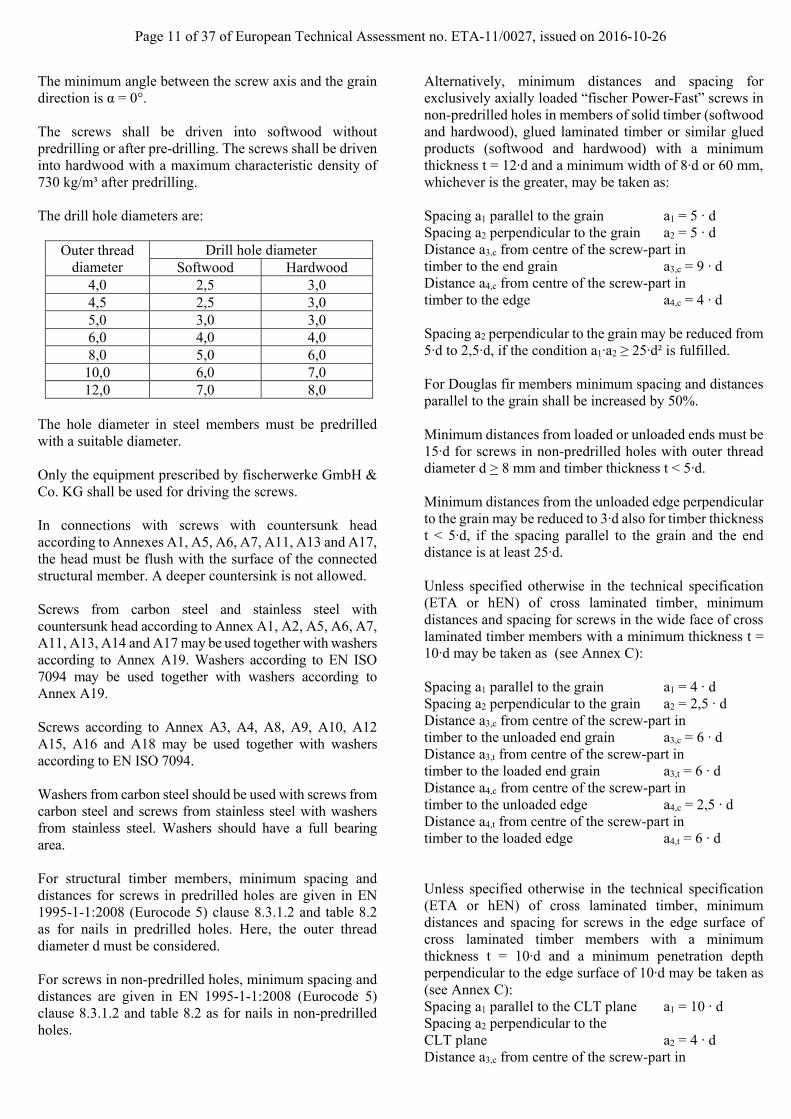
The minimum angle between the screw axis and the grain direction is α = 0°. The screws shall be driven into softwood without predrilling or after pre-drilling. The screws shall be driven into hardwood with a maximum characteristic density of 730 kg/m³ after predrilling. The drill hole diameters are:
Outer thread diameter
Drill hole diameter Softwood Hardwood
4,0 2,5 3,0 4,5 2,5 3,0 5,0 3,0 3,0 6,0 4,0 4,0 8,0 5,0 6,0
10,0 6,0 7,0 12,0 7,0 8,0
The hole diameter in steel members must be predrilled with a suitable diameter. Only the equipment prescribed by fischerwerke GmbH & Co. KG shall be used for driving the screws. In connections with screws with countersunk head according to Annexes A1, A5, A6, A7, A11, A13 and A17, the head must be flush with the surface of the connected structural member. A deeper countersink is not allowed. Screws from carbon steel and stainless steel with countersunk head according to Annex A1, A2, A5, A6, A7, A11, A13, A14 and A17 may be used together with washers according to Annex A19. Washers according to EN ISO 7094 may be used together with washers according to Annex A19. Screws according to Annex A3, A4, A8, A9, A10, A12 A15, A16 and A18 may be used together with washers according to EN ISO 7094. Washers from carbon steel should be used with screws from carbon steel and screws from stainless steel with washers from stainless steel. Washers should have a full bearing area. For structural timber members, minimum spacing and distances for screws in predrilled holes are given in EN 1995-1-1:2008 (Eurocode 5) clause 8.3.1.2 and table 8.2 as for nails in predrilled holes. Here, the outer thread diameter d must be considered. For screws in non-predrilled holes, minimum spacing and distances are given in EN 1995-1-1:2008 (Eurocode 5) clause 8.3.1.2 and table 8.2 as for nails in non-predrilled holes.
Alternatively, minimum distances and spacing for exclusively axially loaded “fischer Power-Fast” screws in non-predrilled holes in members of solid timber (softwood and hardwood), glued laminated timber or similar glued products (softwood and hardwood) with a minimum thickness t = 12∙d and a minimum width of 8∙d or 60 mm, whichever is the greater, may be taken as: Spacing a1 parallel to the grain a1 = 5 ∙ d Spacing a2 perpendicular to the grain a2 = 5 ∙ d Distance a3,c from centre of the screw-part in timber to the end grain a3,c = 9 ∙ d Distance a4,c from centre of the screw-part in timber to the edge a4,c = 4 ∙ d Spacing a2 perpendicular to the grain may be reduced from 5∙d to 2,5∙d, if the condition a1∙a2 ≥ 25∙d² is fulfilled. For Douglas fir members minimum spacing and distances parallel to the grain shall be increased by 50%. Minimum distances from loaded or unloaded ends must be 15∙d for screws in non-predrilled holes with outer thread diameter d > 8 mm and timber thickness t < 5∙d. Minimum distances from the unloaded edge perpendicular to the grain may be reduced to 3∙d also for timber thickness t < 5∙d, if the spacing parallel to the grain and the end distance is at least 25∙d. Unless specified otherwise in the technical specification (ETA or hEN) of cross laminated timber, minimum distances and spacing for screws in the wide face of cross laminated timber members with a minimum thickness t = 10∙d may be taken as (see Annex C): Spacing a1 parallel to the grain a1 = 4 ∙ d Spacing a2 perpendicular to the grain a2 = 2,5 ∙ d Distance a3,c from centre of the screw-part in timber to the unloaded end grain a3,c = 6 ∙ d Distance a3,t from centre of the screw-part in timber to the loaded end grain a3,t = 6 ∙ d Distance a4,c from centre of the screw-part in timber to the unloaded edge a4,c = 2,5 ∙ d Distance a4,t from centre of the screw-part in timber to the loaded edge a4,t = 6 ∙ d Unless specified otherwise in the technical specification (ETA or hEN) of cross laminated timber, minimum distances and spacing for screws in the edge surface of cross laminated timber members with a minimum thickness t = 10∙d and a minimum penetration depth perpendicular to the edge surface of 10∙d may be taken as (see Annex C): Spacing a1 parallel to the CLT plane a1 = 10 ∙ d Spacing a2 perpendicular to the CLT plane a2 = 4 ∙ d Distance a3,c from centre of the screw-part in

Page 12 of 37 of European Technical Assessment no. ETA-11/0027, issued on 2016-10-26
timber to the unloaded end a3,c = 7 ∙ d Distance a3,t from centre of the screw-part in timber to the loaded end a3,t = 12 ∙ d Distance a4,c from centre of the screw-part in timber to the unloaded edge a4,c = 3 ∙ d Distance a4,t from centre of the screw-part in timber to the loaded edge a4,t = 6 ∙ d For a crossed screw couple the minimum spacing between the crossing screws is 1,5∙d. Minimum thickness for structural members is t = 24 mm for screws with outer thread diameter d < 8 mm, t = 30 mm for screws with outer thread diameter d = 8 mm, t = 40 mm for screws with outer thread diameter d = 10 mm and t = 80 mm for screws with outer thread diameter d = 12 mm.

Page 13 of 37 of European Technical Assessment no. ETA-11/0027, issued on 2016-10-26
4 Attestation and verification of constancy
of performance (AVCP) 4.1 AVCP system According to the decision 97/176/EC of the European Commission1, as amended, the system(s) of assessment and verification of constancy of performance (see Annex V to Regulation (EU) No 305/2011) is 3. 5 Technical details necessary for the implementation of the AVCP system, as foreseen in the applicable EAD
Technical details necessary for the implementation of the AVCP system are laid down in the control plan deposited at ETA-Danmark.
Issued in Copenhagen on 2016-10-26 by
Thomas Bruun Managing Director, ETA-Danmark
Page 14 of 37 of European Technical Assessment no. ETA-11/0027, issued on 2016-10-26
fischer Power-Fast and Construction Screws Annex A1 of European Technical Assessment ETA-11/0027
Sizes and Material
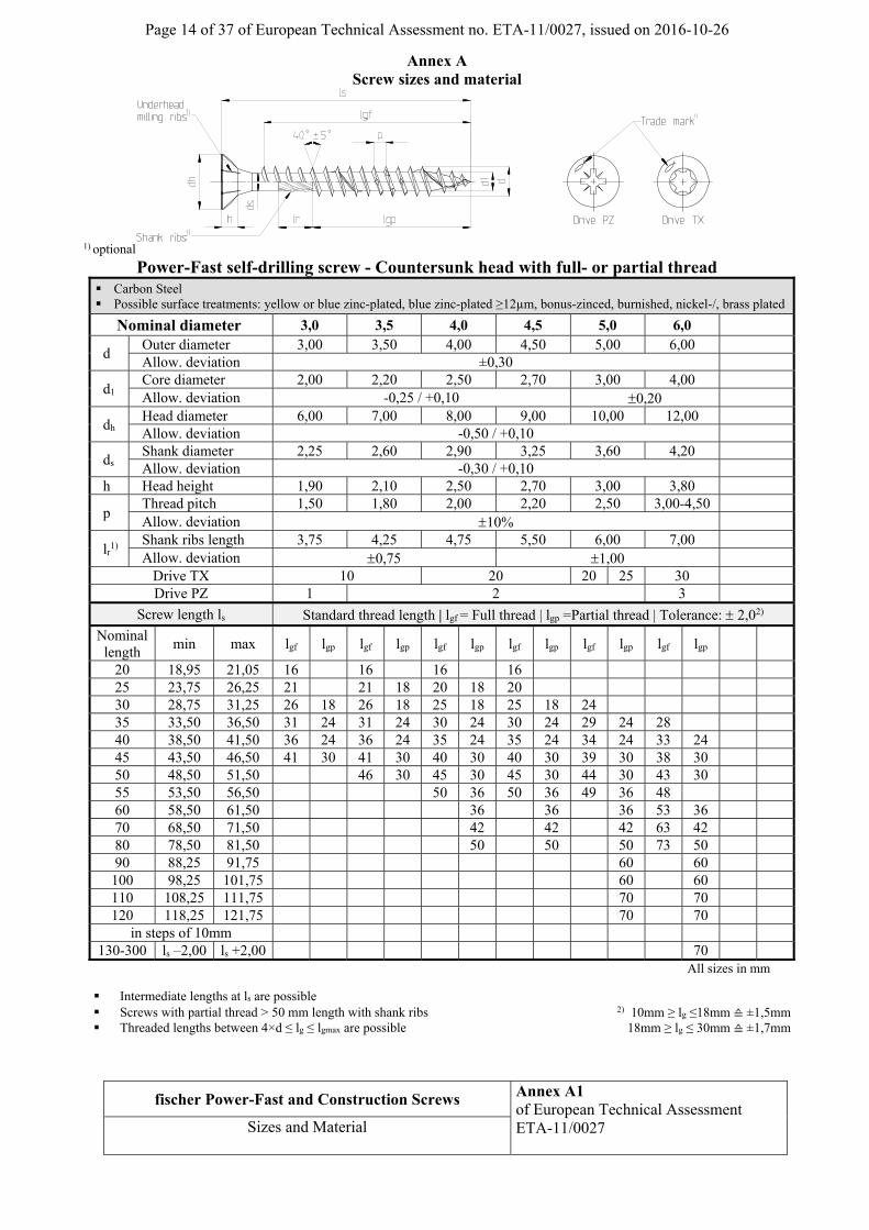
Annex A Screw sizes and material
1) optional
Power-Fast self-drilling screw - Countersunk head with full- or partial thread Carbon Steel Possible surface treatments: yellow or blue zinc-plated, blue zinc-plated ≥12µm, bonus-zinced, burnished, nickel-/, brass plated
Nominal diameter 3,0 3,5 4,0 4,5 5,0 6,0
d Outer diameter 3,00 3,50 4,00 4,50 5,00 6,00
Allow. deviation ±0,30
d1 Core diameter 2,00 2,20 2,50 2,70 3,00 4,00
Allow. deviation -0,25 / +0,10 0,20
dh Head diameter 6,00 7,00 8,00 9,00 10,00 12,00
Allow. deviation -0,50 / +0,10
ds Shank diameter 2,25 2,60 2,90 3,25 3,60 4,20
Allow. deviation -0,30 / +0,10 h Head height 1,90 2,10 2,50 2,70 3,00 3,80
p Thread pitch 1,50 1,80 2,00 2,20 2,50 3,00-4,50
Allow. deviation 10%
lr1)
Shank ribs length 3,75 4,25 4,75 5,50 6,00 7,00
Allow. deviation 0,75 1,00
Drive TX 10 20 20 25 30
Drive PZ 1 2 3
Screw length ls Standard thread length | lgf = Full thread | lgp =Partial thread | Tolerance: 2,02)
Nominal length
min max lgf lgp lgf lgp lgf lgp lgf lgp lgf lgp lgf lgp
20 18,95 21,05 16 16 16 16 25 23,75 26,25 21 21 18 20 18 20 30 28,75 31,25 26 18 26 18 25 18 25 18 24 35 33,50 36,50 31 24 31 24 30 24 30 24 29 24 28 40 38,50 41,50 36 24 36 24 35 24 35 24 34 24 33 24 45 43,50 46,50 41 30 41 30 40 30 40 30 39 30 38 30 50 48,50 51,50 46 30 45 30 45 30 44 30 43 30 55 53,50 56,50 50 36 50 36 49 36 48 60 58,50 61,50 36 36 36 53 36 70 68,50 71,50 42 42 42 63 42 80 78,50 81,50 50 50 50 73 50 90 88,25 91,75 60 60 100 98,25 101,75 60 60 110 108,25 111,75 70 70 120 118,25 121,75 70 70
in steps of 10mm 130-300 ls –2,00 ls +2,00 70
All sizes in mm
Intermediate lengths at ls are possible Screws with partial thread > 50 mm length with shank ribs 2) 10mm ≥ lg ≤18mm ≙ ±1,5mm Threaded lengths between 4×d ≤ lg ≤ lgmax are possible 18mm ≥ lg ≤ 30mm ≙ ±1,7mm
Page 15 of 37 of European Technical Assessment no. ETA-11/0027, issued on 2016-10-26
fischer Power-Fast and Construction Screws Annex A2 of European Technical Assessment ETA-11/0027
Sizes and Material
1) optional
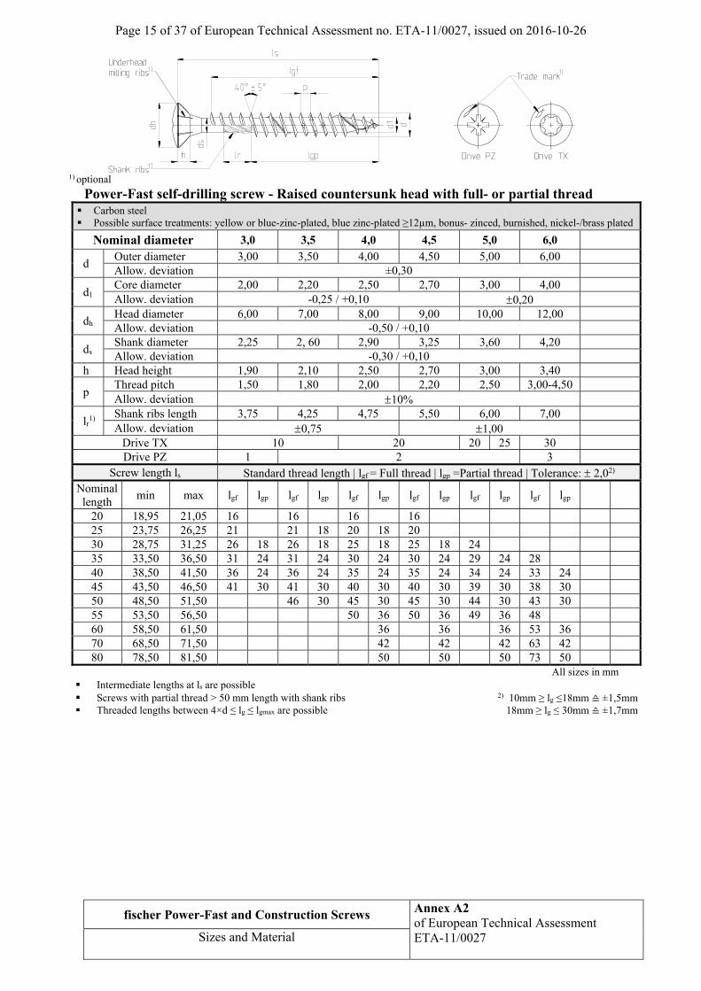
Power-Fast self-drilling screw - Raised countersunk head with full- or partial thread Carbon steel Possible surface treatments: yellow or blue-zinc-plated, blue zinc-plated ≥12µm, bonus- zinced, burnished, nickel-/brass plated
Nominal diameter 3,0 3,5 4,0 4,5 5,0 6,0
d Outer diameter 3,00 3,50 4,00 4,50 5,00 6,00
Allow. deviation ±0,30
d1 Core diameter 2,00 2,20 2,50 2,70 3,00 4,00
Allow. deviation -0,25 / +0,10 0,20
dh Head diameter 6,00 7,00 8,00 9,00 10,00 12,00
Allow. deviation -0,50 / +0,10
ds Shank diameter 2,25 2, 60 2,90 3,25 3,60 4,20
Allow. deviation -0,30 / +0,10
h Head height 1,90 2,10 2,50 2,70 3,00 3,40
p Thread pitch 1,50 1,80 2,00 2,20 2,50 3,00-4,50
Allow. deviation 10%
lr1)
Shank ribs length 3,75 4,25 4,75 5,50 6,00 7,00
Allow. deviation 0,75 1,00
Drive TX 10 20 20 25 30
Drive PZ 1 2 3
Screw length ls Standard thread length | lgf = Full thread | lgp =Partial thread | Tolerance: 2,02) Nominal length
min max lgf lgp lgf lgp lgf lgp lgf lgp lgf lgp lgf lgp
20 18,95 21,05 16 16 16 16
25 23,75 26,25 21 21 18 20 18 20
30 28,75 31,25 26 18 26 18 25 18 25 18 24
35 33,50 36,50 31 24 31 24 30 24 30 24 29 24 28
40 38,50 41,50 36 24 36 24 35 24 35 24 34 24 33 24
45 43,50 46,50 41 30 41 30 40 30 40 30 39 30 38 30
50 48,50 51,50 46 30 45 30 45 30 44 30 43 30
55 53,50 56,50 50 36 50 36 49 36 48
60 58,50 61,50 36 36 36 53 36
70 68,50 71,50 42 42 42 63 42
80 78,50 81,50 50 50 50 73 50
All sizes in mm
Intermediate lengths at ls are possible Screws with partial thread > 50 mm length with shank ribs 2) 10mm ≥ lg ≤18mm ≙ ±1,5mm Threaded lengths between 4×d ≤ lg ≤ lgmax are possible 18mm ≥ lg ≤ 30mm ≙ ±1,7mm
Page 16 of 37 of European Technical Assessment no. ETA-11/0027, issued on 2016-10-26
fischer Power-Fast and Construction Screws Annex A3 of European Technical Assessment ETA-11/0027
Sizes and Material
1) optional
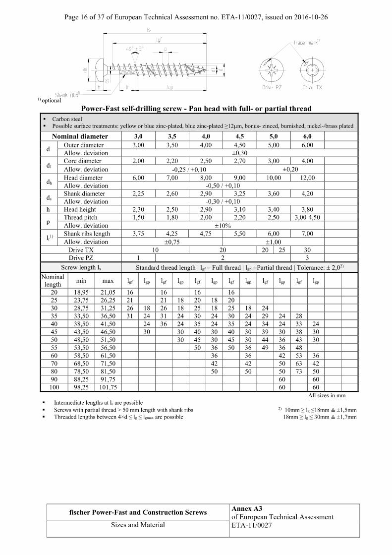
Power-Fast self-drilling screw - Pan head with full- or partial thread Carbon steel Possible surface treatments: yellow or blue zinc-plated, blue zinc-plated ≥12µm, bonus- zinced, burnished, nickel-/brass plated
Nominal diameter 3,0 3,5 4,0 4,5 5,0 6,0
d Outer diameter 3,00 3,50 4,00 4,50 5,00 6,00 Allow. deviation ±0,30
d1 Core diameter 2,00 2,20 2,50 2,70 3,00 4,00 Allow. deviation -0,25 / +0,10 ±0,20
dh Head diameter 6,00 7,00 8,00 9,00 10,00 12,00 Allow. deviation -0,50 / +0,10
ds Shank diameter 2,25 2,60 2,90 3,25 3,60 4,20 Allow. deviation -0,30 / +0,10
h Head height 2,30 2,50 2,90 3,10 3,40 3,80
p Thread pitch 1,50 1,80 2,00 2,20 2,50 3,00-4,50 Allow. deviation 10%
lr1)
Shank ribs length 3,75 4,25 4,75 5,50 6,00 7,00
Allow. deviation 0,75 1,00
Drive TX 10 20 20 25 30 Drive PZ 1 2 3
Screw length ls Standard thread length | lgf = Full thread | lgp =Partial thread | Tolerance: 2,02)
Nominal length
min max lgf lgp lgf lgp lgf lgp lgf lgp lgf lgp lgf lgp
20 18,95 21,05 16 16 16 16 25 23,75 26,25 21 21 18 20 18 20 30 28,75 31,25 26 18 26 18 25 18 25 18 24 35 33,50 36,50 31 24 31 24 30 24 30 24 29 24 28 40 38,50 41,50 24 36 24 35 24 35 24 34 24 33 24 45 43,50 46,50 30 30 40 30 40 30 39 30 38 30 50 48,50 51,50 30 45 30 45 30 44 36 43 30 55 53,50 56,50 50 36 50 36 49 36 48 60 58,50 61,50 36 36 42 53 36 70 68,50 71,50 42 42 50 63 42 80 78,50 81,50 50 50 50 73 50 90 88,25 91,75 60 60 100 98,25 101,75 60 60
All sizes in mm Intermediate lengths at ls are possible Screws with partial thread > 50 mm length with shank ribs 2) 10mm ≥ lg ≤18mm ≙ ±1,5mm Threaded lengths between 4×d ≤ lg ≤ lgmax are possible 18mm ≥ lg ≤ 30mm ≙ ±1,7mm
Page 17 of 37 of European Technical Assessment no. ETA-11/0027, issued on 2016-10-26
fischer Power-Fast and Construction Screws Annex A4 of European Technical Assessment ETA-11/0027
Sizes and Material
1) optional
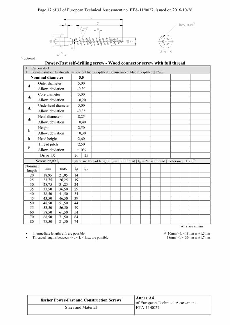
Power-Fast self-drilling screw - Wood connector screw with full thread Carbon steel Possible surface treatments: yellow or blue zinc-plated, Bonus-zinced, blue zinc-plated ≥12µm
Nominal diameter 5,0
d Outer diameter 5,00
Allow. deviation -0,30
d1 Core diameter 3,00
Allow. deviation ±0,20
du Underhead diameter 5,00
Allow. deviation -0,35
dh Head diameter 8,25
Allow. deviation ±0,40
E Height 2,50
Allow. deviation ±0,30
h Head height 2,60
p Thread pitch 2,50
Allow. deviation 10%
Drive TX 20 25
Screw length ls Standard thread length | lgf = Full thread | lgp =Partial thread | Tolerance: 2,02) Nominal length
min max lgf lgp
20 18,95 21,05 14 25 23,75 26,25 19 30 28,75 31,25 24 35 33,50 36,50 29 40 38,50 41,50 34 45 43,50 46,50 39 50 48,50 51,50 44 55 53,50 56,50 49 60 58,50 61,50 54 70 68,50 71,50 64 80 78,50 81,50 74
All sizes in mm
Intermediate lengths at ls are possible 2) 10mm ≥ lg ≤18mm ≙ ±1,5mm Threaded lengths between 4×d ≤ lg ≤ lgmax are possible 18mm ≥ lg ≤ 30mm ≙ ±1,7mm
Page 18 of 37 of European Technical Assessment no. ETA-11/0027, issued on 2016-10-26
fischer Power-Fast and Construction Screws Annex A5 of European Technical Assessment ETA-11/0027
Sizes and Material
1) optional
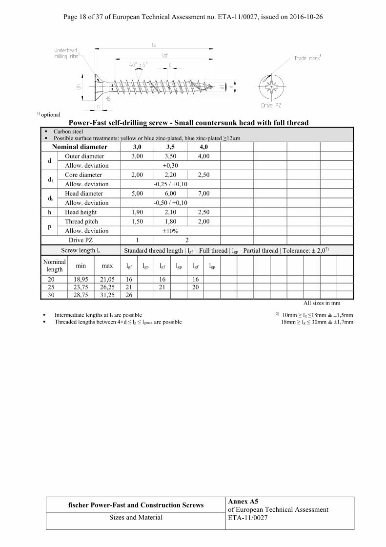
Power-Fast self-drilling screw - Small countersunk head with full thread Carbon steel Possible surface treatments: yellow or blue zinc-plated, blue zinc-plated ≥12µm
Nominal diameter 3,0 3,5 4,0
d Outer diameter 3,00 3,50 4,00
Allow. deviation ±0,30
d1 Core diameter 2,00 2,20 2,50
Allow. deviation -0,25 / +0,10
dh Head diameter 5,00 6,00 7,00
Allow. deviation -0,50 / +0,10
h Head height 1,90 2,10 2,50
p Thread pitch 1,50 1,80 2,00
Allow. deviation 10%
Drive PZ 1 2
Screw length ls Standard thread length | lgf = Full thread | lgp =Partial thread | Tolerance: 2,02)
Nominal length
min max lgf lgp lgf lgp lgf lgp
20 18,95 21,05 16 16 16 25 23,75 26,25 21 21 20 30 28,75 31,25 26
All sizes in mm
Intermediate lengths at ls are possible 2) 10mm ≥ lg ≤18mm ≙ ±1,5mm Threaded lengths between 4×d ≤ lg ≤ lgmax are possible 18mm ≥ lg ≤ 30mm ≙ ±1,7mm

Page 19 of 37 of European Technical Assessment no. ETA-11/0027, issued on 2016-10-26
fischer Power-Fast and Construction Screws Annex A6 of European Technical Assessment ETA-11/0027
Sizes and Material
1) optional
Power-Fast self-drilling screw - Countersunk headhole screw with full thread Carbon steel Possible surface treatments: blue zinc-plated, blue zinc-plated ≥12µm
Nominal diameter 4,0 4,5 5,0 6,0
d Outer diameter 4,00 4,50 5,00 6,00 Allow. deviation ±0,30
d1 Core diameter 2,50 2,70 3,00 4,00 Allow. deviation -0,25 / +0,10 0,20
dh Head diameter 8,00 9,00 10,00 12,00 Allow. deviation -0,50 / +0,10
ds Shank diameter 2,90 3,25 3,60 4,30 Allow. deviation -0,30 / +0,10
h Head height 2,50 2,70 3,00 3,80
p Thread pitch 2,00 2,20 2,50 3,00-4,50 Allow. deviation 10%
ds1 Shank diameter 3,70 3,85 4,50 4,20 Allow. deviation -0,10
Drive PZ 2 3 Screw length ls Standard thread length | lgf = Full thread | lgp =Partial thread | Tolerance: 2,02)
Nominal length
min max lgf lgp lgf lgp lgf lgp lgf lgp
25 23,75 26,25 17,5 27 25,75 28,25 19,5 30 28,75 31,25 22,5 19 35 33,50 36,50 27,5 24 40 38,50 41,50 32,5 29 29 45 43,50 46,50 37,5 34 34 50 48,50 51,50 42,5 39 39 41 55 53,50 56,50 47,5 44 44 46 60 58,50 61,50 50,0 49 49 51 70 68,50 71,50 59 60 60 80 78,50 81,50 59 60 60 90 88,25 91,75 59 60 60
100 98,25 101,75 60 60 All sizes in mm
Intermediate lengths at ls are possible 2) 10mm ≥ lg ≤18mm ≙ ±1,5mm Threaded lengths between 4×d ≤ lg ≤ lgmax are possible 18mm ≥ lg ≤ 30mm ≙ ±1,7mm
Page 20 of 37 of European Technical Assessment no. ETA-11/0027, issued on 2016-10-26
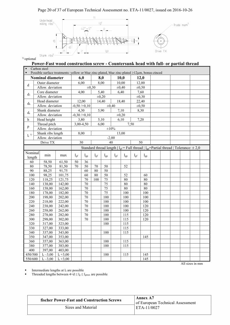
fischer Power-Fast and Construction Screws Annex A7 of European Technical Assessment ETA-11/0027
Sizes and Material
1) optional
Power-Fast wood construction screw - Countersunk head with full- or partial thread Carbon steel Possible surface treatments: yellow or blue zinc-plated, blue zinc-plated ≥12µm, bonus-zinced
Nominal diameter 6,0 8,0 10,0 12,0
d Outer diameter 6,00 8,00 10,00 12,00 Allow. deviation ±0,30 ±0,40 ±0,50
d1 Core diameter 4,00 5,40 6,40 7,60 Allow. deviation ±0,20 ±0,30
dh Head diameter 12,00 14,40 18,40 22,40 Allow. deviation -0,50 /+0,10 ±0,40 ±0,50
ds Shank diameter 4,30 5,90 7,10 8,30 Allow. deviation -0,30 /+0,10 ±0,20
h Head height 3,80 5,10 6,10 7,20
p Thread pitch 3,00-4,50 6,00 7,50 Allow. deviation ±10%
lr 1) Shank ribs length 8,00 13,00 Allow. deviation -2,00
Drive TX 30 40 50
Standard thread length | lgf = Full thread | lgp=Partial thread | Tolerance: 2,0
Nominal length
min max lgf lgp lgf lgp lgf lgp lgf lgp
60 58,50 61,50 50 36 80 78,50 81,50 70 50 70 50 52 90 88,25 91,75 60 80 50
100 98,25 101,75 60 80 50 52 60 120 118,25 121,75 70 100 75 80 80 140 138,00 142,00 70 75 80 80 160 158,00 162,00 70 75 80 80 180 178,00 182,00 70 75 100 100 200 198,00 202,00 70 100 100 100 220 218,00 222,00 70 100 100 100 240 238,00 242,00 70 100 100 120 260 258,00 262,00 70 100 100 120 280 278,00 282,00 70 100 115 120 300 298,00 302,00 70 100 115 120 320 317,00 323,00 100 115 330 327,00 333,00 115 340 337,00 343,00 100 115 350 347,00 353,00 145 360 357,00 363,00 100 115 380 377,00 383,00 100 115 400 397,00 403,00
450/500 ls –3,00 ls +3,00 100 115 145 550/600 ls –3,00 ls +3,00 145
All sizes in mm
Intermediate lengths at ls are possible Threaded lengths between 4×d ≤ lg ≤ lgmax are possible
Page 21 of 37 of European Technical Assessment no. ETA-11/0027, issued on 2016-10-26
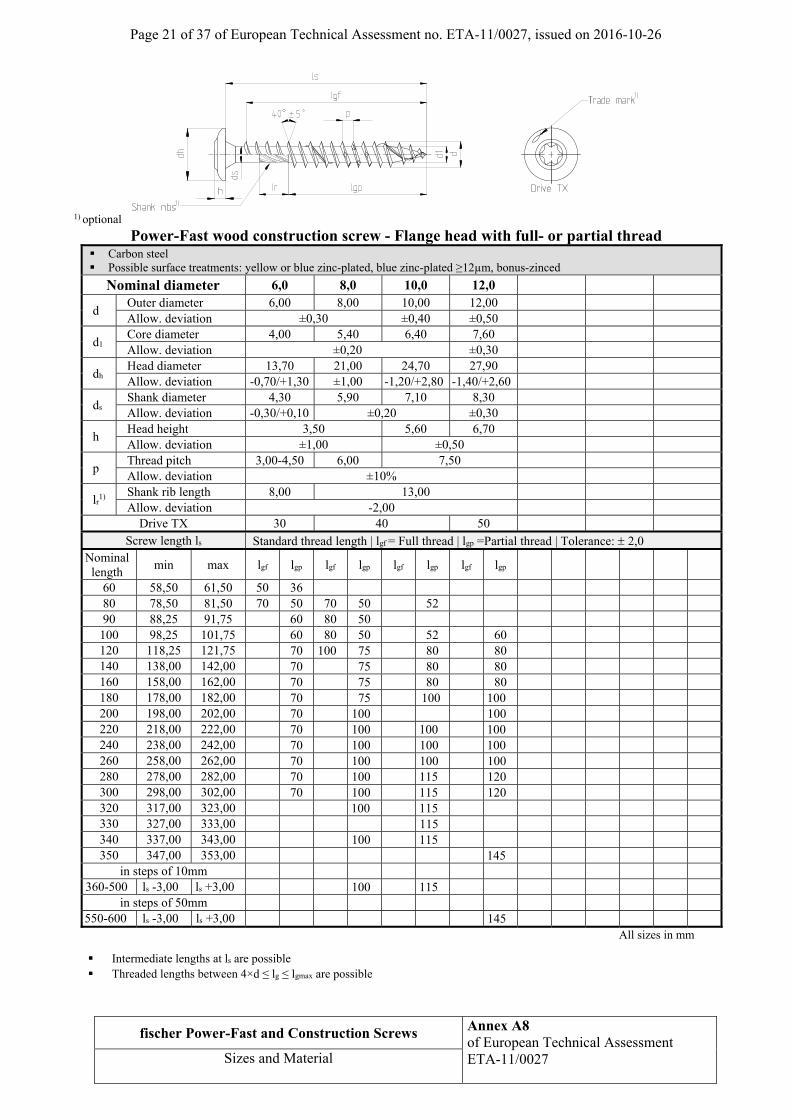
fischer Power-Fast and Construction Screws Annex A8 of European Technical Assessment ETA-11/0027
Sizes and Material
1) optional
Power-Fast wood construction screw - Flange head with full- or partial thread Carbon steel Possible surface treatments: yellow or blue zinc-plated, blue zinc-plated ≥12µm, bonus-zinced
Nominal diameter 6,0 8,0 10,0 12,0
d Outer diameter 6,00 8,00 10,00 12,00 Allow. deviation ±0,30 ±0,40 ±0,50
d1 Core diameter 4,00 5,40 6,40 7,60 Allow. deviation ±0,20 ±0,30
dh Head diameter 13,70 21,00 24,70 27,90 Allow. deviation -0,70/+1,30 ±1,00 -1,20/+2,80 -1,40/+2,60
ds Shank diameter 4,30 5,90 7,10 8,30 Allow. deviation -0,30/+0,10 ±0,20 ±0,30
h Head height 3,50 5,60 6,70 Allow. deviation ±1,00 ±0,50
p Thread pitch 3,00-4,50 6,00 7,50 Allow. deviation ±10%
lr1)
Shank rib length 8,00 13,00 Allow. deviation -2,00
Drive TX 30 40 50 Screw length ls Standard thread length | lgf = Full thread | lgp =Partial thread | Tolerance: 2,0
Nominal length
min max lgf lgp lgf lgp lgf lgp lgf lgp
60 58,50 61,50 50 36 80 78,50 81,50 70 50 70 50 52 90 88,25 91,75 60 80 50
100 98,25 101,75 60 80 50 52 60 120 118,25 121,75 70 100 75 80 80 140 138,00 142,00 70 75 80 80 160 158,00 162,00 70 75 80 80 180 178,00 182,00 70 75 100 100 200 198,00 202,00 70 100 100 220 218,00 222,00 70 100 100 100 240 238,00 242,00 70 100 100 100 260 258,00 262,00 70 100 100 100 280 278,00 282,00 70 100 115 120 300 298,00 302,00 70 100 115 120 320 317,00 323,00 100 115 330 327,00 333,00 115 340 337,00 343,00 100 115 350 347,00 353,00 145
in steps of 10mm 360-500 ls -3,00 ls +3,00 100 115
in steps of 50mm 550-600 ls -3,00 ls +3,00 145
All sizes in mm
Intermediate lengths at ls are possible Threaded lengths between 4×d ≤ lg ≤ lgmax are possible

Page 22 of 37 of European Technical Assessment no. ETA-11/0027, issued on 2016-10-26
fischer Power-Fast and Construction Screws Annex A9 of European Technical Assessment ETA-11/0027
Sizes and Material
1) optional
Power-Fast wood construction screw - Hexagon head with full- or partial thread Carbon steel Possible surface treatments: yellow or blue zinc-plated, blue zinc-plated ≥12µm, bonus-zinced
Nominal diameter 6,0 8,0 10,0 12,0
d Outer diameter 6,00 8,00 10,00 12,00 Allow. deviation ±0,30 ±0,40 ±0,50
d1 Core diameter 4,00 5,40 6,40 7,60 Allow. deviation ±0,20 ±0,30
du Underhead diameter 6,25 8,25 10,30 12,40 Allow. deviation -0,80 -0,90 -1,00
SW Wrench size 9,90 12,80 14,80 16,80 Allow. deviation ±0,30
E Height 2,00 2,10 2,30 3,30 Allow. deviation ±0,50
ds Shank diameter 4,30 5,90 7,10 8,30 Allow. deviation -0,30/+0,10 ±0,20
h Head height 4,00 4,50 5,20 5,70 Allow. deviation ±0,30 ±0,40 ±0,50
p Thread pitch 3,00-4,50 6,00 7,50 Allow. deviation 10%
lr1)
Shank rib length 8,00 13,00 Allow. deviation -2,00
Drive TX 30 40 50
Screw length ls Standard thread length | lgf = Full thread | lgp =Partial thread | Tolerance: 2,02)
Nominal length
min max lgf lgp lgf lgp lgf lgp lgf lgp
60 58,5 61,5 50 30 80 78,5 81,5 70 50 70 50 52 90 88,25 91,75 60 80 50 100 98,25 101,75 60 80 50 52 60 120 118,25 121,75 70 100 75 80 80
140/160 ls –2,00 ls +2,00 70 75 80 80 180 178,00 182,00 70 75 100 100
200/220 ls –2,00 ls +2,00 70 100 100 100 240/260 ls –2,00 ls +2,00 70 100 100 120 280/300 ls –2,00 ls +2,00 70 100 115 120
320 317,00 323,00 100 115 330 327,00 333,00 115 340 337,00 343,00 100 115 350 347,00 353,00 145
360/380 ls –3,00 ls +3,00 100 115 in steps of 50mm
400-500 ls –3,00 ls +3,00 100 115 145 550/600 ls –3,00 ls +3,00 145
All sizes in mm
Intermediate lengths at ls are possible Threaded lengths between 4×d ≤ lg ≤ lgmax are possible 2) 18mm ≥ lg ≤ 30mm ≙ ±1,7mm

Page 23 of 37 of European Technical Assessment no. ETA-11/0027, issued on 2016-10-26
fischer Power-Fast and Construction Screws Annex A10 of European Technical Assessment ETA-11/0027
Sizes and Material
1) optional
Power-Fast wood construction screw - Hexagon head with washer and full- or partial thread Carbon steel Possible surface treatments: yellow or blue zinc-plated, blue zinc-plated ≥12µm, bonus-zinced
Nominal diameter 6,0 8,0 10,0 12,0
d Outer diameter 6,00 8,00 10,00 12,00 Allow. deviation ±0,30 ±0,40 ±0,50
d1 Core diameter 4,00 5,40 6,40 7,60 Allow. deviation ±0,20 ±0,30
dh Head diameter 15,00 18,00 21,50 23,40 Allow. deviation 1,20 1,50
du Underhead diameter 6,25 8,25 10,30 12,40 Allow. deviation -0,80 -0,90 -1,00
SW Wrench size 9,90 12,80 14,80 16,80 Allow. deviation ±0,30
c Washer height 1,80 2,00 2,20 2,50
E Height 2,00 2,10 2,30 3,30 Allow. deviation ±0,50
ds Shank diameter 4,30 5,90 7,10 8,30 Allow. deviation -0,30/+0,10 ±0,20
h Head height 4,00 4,50 5,20 5,70 Allow. deviation ±0,30 ±0,40 ±0,50
p Thread pitch 3,00-4,50 6,00 7,50 Allow. deviation 10%
lr1)
Shank rib length 8,00 13,00 Allow. deviation -2,00
Drive TX 30 40 50 Screw length ls Standard thread length | lgf = Full thread | lgp =Partial thread | Tolerance: 2,02)
Nominal length
min max lgf lgp lgf lgp lgf lgp lgf lgp
60 58,50 61,50 50 30 80 78,50 81,50 70 50 70 50 52 90 88,25 91,75 60 80 50
100 98,25 101,75 60 80 50 52 60 120 118,25 121,75 70 100 75 80 80
140/160 ls –2,00 ls +2,00 70 75 80 80 180 178,00 182,00 70 75 100 100
200/220 ls –2,00 ls +2,00 70 100 100 100 240/260 ls –2,00 ls +2,00 70 100 100 120 280/300 ls –2,00 ls +2,00 70 100 115 120
320 317,00 323,00 100 115 330 327,00 333,00 115 340 337,00 343,00 100 115 350 347,00 353,00 145
360/380 ls –3,00 ls +3,00 100 115 in steps of 50mm
400-500 ls –3,00 ls +3,00 100 115 145 550/600 ls –3,00 ls +3,00 145
All sizes in mm Intermediate lengths at ls are possible Threaded lengths between 4×d ≤ lg ≤ lgmax are possible 2) 18mm ≥ lg ≤ 30mm ≙ ±1,7mm
Page 24 of 37 of European Technical Assessment no. ETA-11/0027, issued on 2016-10-26
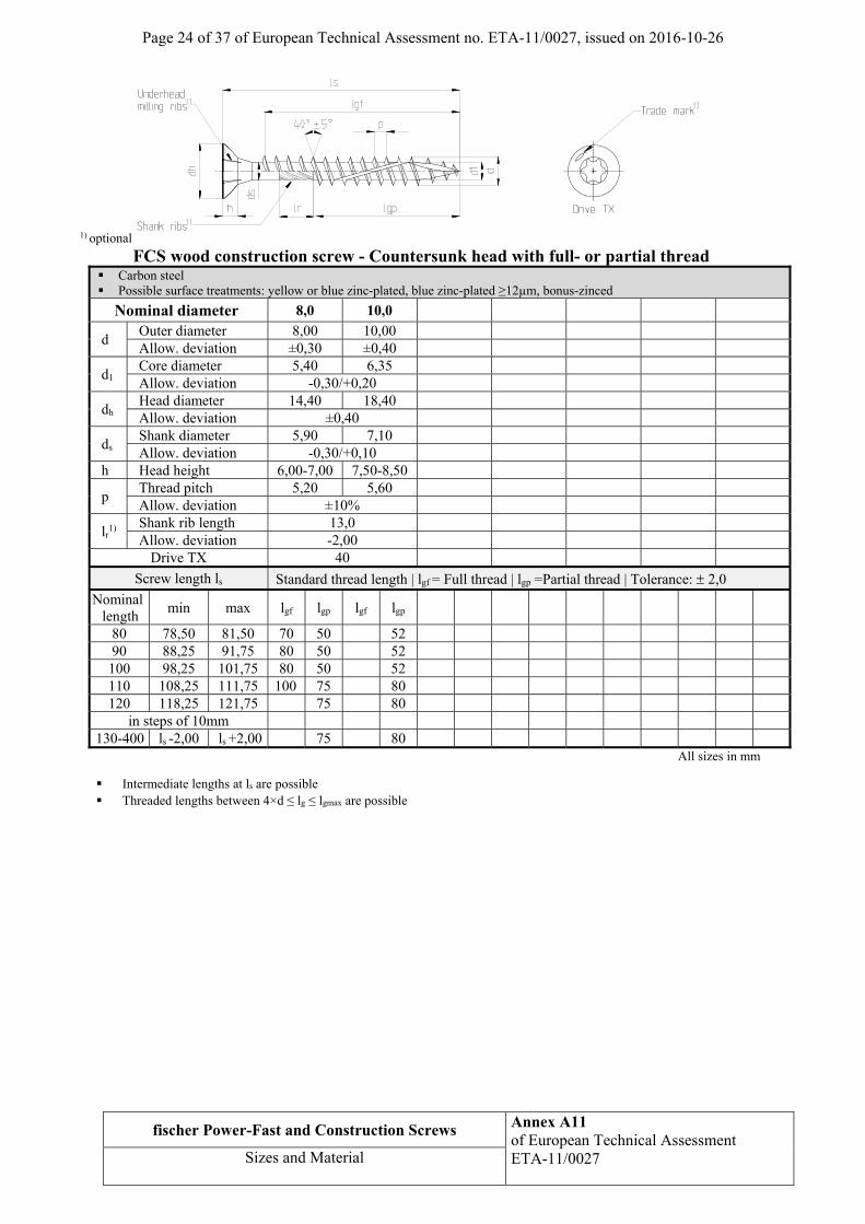
fischer Power-Fast and Construction Screws Annex A11 of European Technical Assessment ETA-11/0027
Sizes and Material
1) optional
FCS wood construction screw - Countersunk head with full- or partial thread Carbon steel Possible surface treatments: yellow or blue zinc-plated, blue zinc-plated ≥12µm, bonus-zinced
Nominal diameter 8,0 10,0
d Outer diameter 8,00 10,00 Allow. deviation ±0,30 ±0,40
d1 Core diameter 5,40 6,35 Allow. deviation -0,30/+0,20
dh Head diameter 14,40 18,40 Allow. deviation ±0,40
ds Shank diameter 5,90 7,10 Allow. deviation -0,30/+0,10
h Head height 6,00-7,00 7,50-8,50
p Thread pitch 5,20 5,60 Allow. deviation ±10%
lr1)
Shank rib length 13,0 Allow. deviation -2,00
Drive TX 40
Screw length ls Standard thread length | lgf = Full thread | lgp =Partial thread | Tolerance: 2,0
Nominal length
min max lgf lgp lgf lgp
80 78,50 81,50 70 50 52 90 88,25 91,75 80 50 52 100 98,25 101,75 80 50 52 110 108,25 111,75 100 75 80 120 118,25 121,75 75 80
in steps of 10mm 130-400 ls -2,00 ls +2,00 75 80
All sizes in mm
Intermediate lengths at ls are possible Threaded lengths between 4×d ≤ lg ≤ lgmax are possible

Page 25 of 37 of European Technical Assessment no. ETA-11/0027, issued on 2016-10-26
fischer Power-Fast and Construction Screws Annex A12 of European Technical Assessment ETA-11/0027
Sizes and Material
1) optional
FCS wood construction screw - Flange head with partial thread Carbon steel Possible surface treatments: yellow or blue zinc-plated, blue zinc-plated ≥12µm
Nominal diameter 8,0 10,0
d Outer diameter 8,00 10,00 Allow. deviation -0,40/+0,30 ±0,40
d1 Core diameter 5,40 6,35 Allow. deviation ±0,30
dh Head diameter 21,00 24,70 Allow. deviation ±1,00 -1,20/+2,80
ds Shank diameter 5,90 7,10 Allow. deviation -0,30/+0,20
h Head height 2,50-4,50 3,70-5,70
p Thread pitch 5,20 5,60 Allow. deviation ±10%
lr1)
Shank rib length 12,00 Allow. deviation ±1,00
Drive TX 40
Screw length ls Standard thread length | lgf = Full thread | lgp =Partial thread | Tolerance: 2,0
Nominal length
min max lgf lgp lgf lgp
80 78,50 81,50 70 50 52 90 88,25 91,75 80 50 52 100 98,25 101,75 80 50 52 110 108,25 111,75 100 75 80 120 118,25 121,75 75 80
in steps pf 10mm 130-400 ls -2,00 ls +2,00 75 80
All sizes in mm
Intermediate lengths at ls are possible Threaded lengths between 4×d ≤ lg ≤ lgmax are possible

Page 26 of 37 of European Technical Assessment no. ETA-11/0027, issued on 2016-10-26
fischer Power-Fast and Construction Screws Annex A13 of European Technical Assessment ETA-11/0027
Sizes and Material
1) optional
Power-Fast self-drilling screw - Countersunk head with full- or partial thread
Stainless steel
Nominal diameter 3,0 3,5 4,0 4,5 5,0 6,0
d Outer diameter 3,00 3,50 4,00 4,50 5,00 6,00 Allow. deviation ±0,30
d1 Core diameter 2,00 2,20 2,50 2,70 3,00 4,00 Allow. deviation -0,25 / +0,10 ±0,20
dh Head diameter 6,00 7,00 8,00 9,00 10,00 12,00 Allow. deviation -0,50 / +0,10
ds Shank diameter 2,25 2,60 2,90 3,25 3,60 4,30 Allow. deviation -0,30 / +0,10
h Head height 1,90 2,10 2,50 2,70 3,00 3,80
p Thread pitch 1,50 1,80 2,00 2,20 2,50 3,00-4,50 Allow. deviation ±10%
lr1)
Shank rib length 3,75 4,25 4,75 5,50 6,00 7,00 Allow. deviation ±0,75 ±1,00
Drive TX 10 20 20 25 30 Drive PZ 1 2 3
Screw length ls Standard thread length | lgf = Full- thread | lgp =Partial thread | Tolerance: 2,02)
Nominal length
min max lgf lgp lgf lgp lgf lgp lgf lgp lgf lgp lgf lgp
20 18,95 21,05 16 16 16 16 25 23,75 26,25 21 21 18 20 18 20 30 28,75 31,25 26 18 26 18 25 18 25 18 24 35 33,50 36,50 31 24 31 24 30 24 30 24 29 24 28 40 38,50 41,50 36 24 36 24 35 24 35 24 34 24 33 24 45 43,50 46,50 41 30 41 30 40 30 40 30 39 30 38 30 50 48,50 51,50 46 30 45 30 45 30 44 30 43 30 55 53,50 56,50 50 36 50 36 49 36 48 60 58,50 61,50 36 36 36 53 36 70 68,50 71,50 42 42 42 63 42 80 78,50 81,50 50 50 50 73 50 90 88,25 91,75 60 60 100 98,25 101,75 60 60 110 108,25 111,75 70 70 120 118,25 121,75 70 70
in steps of 10mm 130-300 ls –2,00 ls +2,00 70
All sizes in mm
Intermediate lengths at ls are possible Screws with partial thread > 50 mm length with shank ribs 2) 10mm ≥ lg ≤18mm ≙ ±1,5mm Threaded lengths between 4×d ≤ lg ≤ lgmax are possible 18mm ≥ lg ≤ 30mm ≙ ±1,7mm
Page 27 of 37 of European Technical Assessment no. ETA-11/0027, issued on 2016-10-26
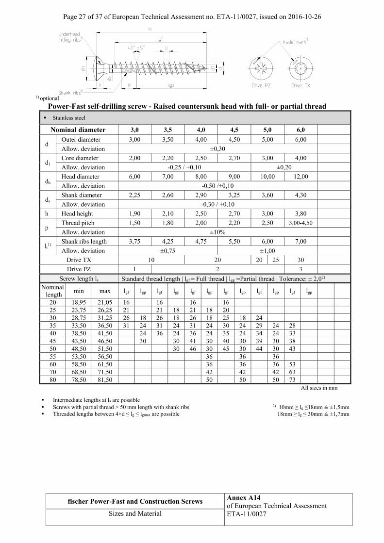
fischer Power-Fast and Construction Screws Annex A14 of European Technical Assessment ETA-11/0027
Sizes and Material
1) optional
Power-Fast self-drilling screw - Raised countersunk head with full- or partial thread
Stainless steel
Nominal diameter 3,0 3,5 4,0 4,5 5,0 6,0
d Outer diameter 3,00 3,50 4,00 4,50 5,00 6,00
Allow. deviation ±0,30
d1 Core diameter 2,00 2,20 2,50 2,70 3,00 4,00
Allow. deviation -0,25 / +0,10 ±0,20
dh Head diameter 6,00 7,00 8,00 9,00 10,00 12,00
Allow. deviation -0,50 /+0,10
ds Shank diameter 2,25 2,60 2,90 3,25 3,60 4,30
Allow. deviation -0,30 / +0,10
h Head height 1,90 2,10 2,50 2,70 3,00 3,80
p Thread pitch 1,50 1,80 2,00 2,20 2,50 3,00-4,50
Allow. deviation ±10%
lr1)
Shank ribs length 3,75 4,25 4,75 5,50 6,00 7,00
Allow. deviation 0,75 1,00
Drive TX 10 20 20 25 30
Drive PZ 1 2 3
Screw length ls Standard thread length | lgf = Full thread | lgp =Partial thread | Tolerance: 2,02) Nominal
length min max lgf lgp lgf lgp lgf lgp lgf lgp lgf lgp lgf lgp
20 18,95 21,05 16 16 16 16 25 23,75 26,25 21 21 18 21 18 20 30 28,75 31,25 26 18 26 18 26 18 25 18 24 35 33,50 36,50 31 24 31 24 31 24 30 24 29 24 28 40 38,50 41,50 24 36 24 36 24 35 24 34 24 33 45 43,50 46,50 30 30 41 30 40 30 39 30 38 50 48,50 51,50 30 46 30 45 30 44 30 43 55 53,50 56,50 36 36 36 60 58,50 61,50 36 36 36 53 70 68,50 71,50 42 42 42 63 80 78,50 81,50 50 50 50 73
All sizes in mm
Intermediate lengths at ls are possible Screws with partial thread > 50 mm length with shank ribs 2) 10mm ≥ lg ≤18mm ≙ ±1,5mm Threaded lengths between 4×d ≤ lg ≤ lgmax are possible 18mm ≥ lg ≤ 30mm ≙ ±1,7mm

Page 28 of 37 of European Technical Assessment no. ETA-11/0027, issued on 2016-10-26
fischer Power-Fast and Construction Screws Annex A15 of European Technical Assessment ETA-11/0027
Sizes and Material
1) optional
Power-Fast self-drilling screw - Pan head with full- or partial thread
Stainless steel
Nominal diameter 3,0 3,5 4,0 4,5 5,0 6,0
d Outer diameter 3,00 3,50 4,00 4,50 5,00 6,00 Allow. deviation ±0,30
d1 Core diameter 2,00 2,20 2,50 2,70 3,00 4,00 Allow. deviation -0,25 / +0,10 ±0,20
dh Head diameter 6,00 7,00 8,00 9,00 10,00 12,00 Allow. deviation -0,50 / +0,10
ds Shank diameter 2,25 2,60 2,90 3,25 3,60 4,30 Allow. deviation -0,30 / +0,10
h Head height 2,30 2,50 2,90 3,10 3,40 3,80
p Thread pitch 1,50 1,80 2,00 2,20 2,50 3,00-4,50 Allow. deviation ±10%
lr1)
Shank ribs length 3,75 4,25 4,75 5,50 6,00 7,00 Allow. deviation 0,75 1,00
Drive TX 10 20 20 25 30
Drive PZ 1 2 3
Screw length ls Standard thread length | lgf = Full thread | lgp =Partial thread | Tolerance: 2,02)
Nominal length
min max lgf lgp lgf lgp lgf lgp lgf lgp lgf lgp lgf lgp
20 18,95 21,05 16 16 16 25 23,75 26,25 21 21 18 20 18 20 30 28,75 31,25 26 18 26 18 25 18 25 18 24 35 33,50 36,50 31 24 31 24 30 24 30 24 29 24 28 40 38,50 41,50 24 36 24 35 24 35 24 34 24 33 24 45 43,50 46,50 30 30 40 30 40 30 39 30 38 30 50 48,50 51,50 30 45 30 45 30 44 36 43 30 55 53,50 56,50 50 36 50 36 49 36 48 60 58,50 61,50 36 36 42 53 36 70 68,50 71,50 42 42 50 63 42 80 78,50 81,50 50 50 50 73 50 90 88,25 91,75 60 60
100 98,25 101,75 60 60 All sizes in mm
Intermediate lengths at ls are possible Screws with partial thread > 50 mm length with shank ribs 2) 10mm ≥ lg ≤18mm ≙ ±1,5mm Threaded lengths between 4×d ≤ lg ≤ lgmax are possible 18mm ≥ lg ≤ 30mm ≙ ±1,7mm
Page 29 of 37 of European Technical Assessment no. ETA-11/0027, issued on 2016-10-26
fischer Power-Fast and Construction Screws Annex A16 of European Technical Assessment ETA-11/0027
Sizes and Material
1) optional
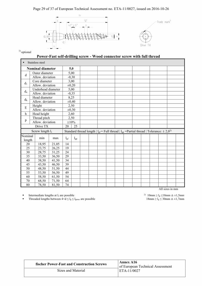
Power-Fast self-drilling screw - Wood connector screw with full thread
Stainless steel
Nominal diameter 5,0
d Outer diameter 5,00 Allow. deviation -0,30
d1 Core diameter 3,00 Allow. deviation ±0,20
du Underhead diameter 5,00 Allow. deviation -0,35
dh Head diameter 8,25 Allow. deviation ±0,40
E Height 2,50 Allow. deviation ±0,30
h Head height 2,60
p Thread pitch 2,50 Allow. deviation 10%
Drive TX 20 25
Screw length ls Standard thread length | lgf = Full thread | lgp =Partial thread | Tolerance: 2,02)
Nominal length
min max lgf lgp
20 18,95 21,05 14 25 23,75 26,25 19 30 28,75 31,25 24 35 33,50 36,50 29 40 38,50 41,50 34 45 43,50 46,50 39 50 48,50 51,50 44 55 53,50 56,50 49 60 58,50 61,50 54 70 68,50 71,50 64 80 78,50 81,50 74
All sizes in mm
Intermediate lengths at ls are possible 2) 10mm ≥ lg ≤18mm ≙ ±1,5mm Threaded lengths between 4×d ≤ lg ≤ lgmax are possible 18mm ≥ lg ≤ 30mm ≙ ±1,7mm
Page 30 of 37 of European Technical Assessment no. ETA-11/0027, issued on 2016-10-26
fischer Power-Fast and Construction Screws Annex A17 of European Technical Assessment ETA-11/0027
Sizes and Material
1) optional
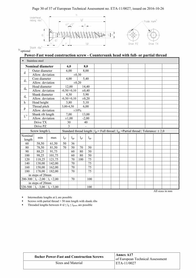
Power-Fast wood construction screw - Countersunk head with full- or partial thread
Stainless steel
Nominal diameter 6,0 8,0
d Outer diameter 6,00 8,00 Allow. deviation ±0,30
d1 Core diameter 4,00 5,40 Allow. deviation ±0,20
dh Head diameter 12,00 14,40 Allow. deviation -0,50/+0,10 ±0,40
ds Shank diameter 4,30 5,90 Allow. deviation -0,30/+0,10 ±0,20
h Head height 3,80 5,10
p Thread pitch 3,00-4,50 6,00 Allow. deviation ±10%
lr1)
Shank rib length 7,00 13,00 Allow. deviation ±1,00 -2,00
Drive TX 30 40 Drive PZ 3 -
Screw length ls Standard thread length | lgf = Full thread | lgp =Partial thread | Tolerance: 2,0
Nominal length
min max lgf lgp lgf lgp
60 58,50 61,50 50 36 80 78,50 81,50 70 50 70 50 90 88,25 91,75 60 80 50
100 98,25 101,75 60 80 50 120 118,25 121,75 70 100 75 140 138,00 142,00 70 75 160 158,00 162,00 70 75 180 178,00 182,00 70 75
in steps of 20mm 200-300 ls –2,00 ls +2,00 70 100
in steps of 20mm 320-500 ls –3,00 ls +3,00 100
All sizes in mm
Intermediate lengths at ls are possible Screws with partial thread > 50 mm length with shank ribs Threaded lengths between 4×d ≤ lg ≤ lgmax are possible

Page 31 of 37 of European Technical Assessment no. ETA-11/0027, issued on 2016-10-26
fischer Power-Fast and Construction Screws Annex A18 of European Technical Assessment ETA-11/0027
Sizes and Material
1) optional
Power-Fast wood construction screw - Flange head with full- or partial thread
Stainless steel
Nominal diameter 6,0 8,0
d Outer diameter 6,00 8,00 Allow. deviation ±0,30
d1 Core diameter 4,00 5,40 Allow. deviation -0,30/+0,20
dh Head diameter 13,70 21,00 Allow. deviation -0,70/+1,30 ±1,00
ds Shank diameter 4,30 5,90 Allow. deviation -0,30/+0,10
h Head height 3,50 Allow. deviation ±1,00
p Thread pitch 3,00-4,50 6,00 Allow. deviation ±10%
lr1)
Shank rib length 8,00 13,00 Allow. deviation -2,00
Drive TX 30 40 Screw length ls Standard thread length | lgf = Full thread | lgp =Partial thread | Tolerance: 2,0
Nominal length
min max lgf lgp lgf lgp
60 58,50 61,50 50 36 80 78,50 81,50 70 50 70 50 90 88,25 91,75 60 80 50 100 98,25 101,75 60 80 50 120 118,25 121,75 70 100 75 140 138,00 142,00 70 75 160 158,00 162,00 70 75 180 178,00 182,00 70 75
in steps of 20mm 200-300 ls –2,00 ls +2,00 70 100
in steps of 20mm 320-500 ls –3,00 ls +3,00 100
All sizes in mm
Intermediate lengths at ls are possible Threaded lengths between 4×d ≤ lg ≤ lgmax are possible

Page 32 of 37 of European Technical Assessment no. ETA-11/0027, issued on 2016-10-26
fischer Power-Fast and Construction Screws Annex A19 of European Technical Assessment ETA-11/0027
Assessories
Washer for Power-Fast and construction screws Carbon Steel - possible surface treatments: yellow or blue zinc-plated, bonus- zinced, ≥12µm blue zinc-plated Stainless steel
Nominal diameter Type 1 Type 2
Size 6 8 10 12 6 8 10
db Inner diameter 6,70 8,70 11,20 6,70 6,70 8,70 11,20 Allow. deviation -0,40
da Outer diameter 21 30 35 43 21 25,50 30,50 Allow. deviation ±2,0
b Height 4,70 5,20 6,20 8,30 4,70 5,20 6,20 Allow. deviation -0,40
h Height 1,50 1,80 2,00 2,20 1,50 1,80 2,00 Allow. deviation -0,15
All sizes in mm

Page 33 of 37 of European Technical Assessment no. ETA-11/0027, issued on 2016-10-26
fischer Power-Fast and Construction Screws Annex B1 of European Technical Assessment ETA-11/0027
Fixing of on-roof insulation system
Annex B Fixing of on-roof insulation system
WS = Wind suction WP = Wind pressure es = Spacing of screws lef = Thread part part of screw in rafter β = Roof inclination α = Angle between axis of screw and axis of rafter
α
Counter batten
Insulation
Rafter
Vapour barrier
Roof boards
Dead load dL and snow load sL
Wind Ws
Wp
Concentrated transfer of pressure within the insulation
Axis of screw, tension load Fz
Pressure transfer within the insulation
Rafter
β
α
lef
es
es
es
β
Axis of counter batten

Page 34 of 37 of European Technical Assessment no. ETA-11/0027, issued on 2016-10-26
fischer Power-Fast and Construction Screws Annex B3 of European Technical Assessment ETA-11/0027
Design
Design of the battens
The bending stresses are calculated as:
b s char(F F )
M4
Where
char = characteristic length
4charef
4 EI
w K
EI = bending stiffness of the batten K = coefficient of subgrade wef = effective width of the heat insulation
Fb = Point loads perpendicular to the battens
Fs = Point loads perpendicular to the battens, load application in the area of the screw heads
The coefficient of subgrade K may be calculated from the modulus of elasticity EHI and the thickness tHI of the heat insulation if the effective width wef of the heat insulation under compression is known. Due to the load extension in the heat insulation the effective width wef is greater than the width of the batten or rafter, respectively. For further calculations, the effective width wef of the heat insulation may be determined according to:
ef HIw w t / 2
where w = minimum width of the batten or rafter, respectively tHI = thickness of the heat insulation
HI
HI
EK
t
The following condition shall be satisfied:
m,d d
m,d m,d
M1
f W f
For the calculation of the section modulus W the net cross section has to be considered.
The shear stresses shall be calculated according to:
b s(F F )V
2
The following condition shall be satisfied:
d d
v,d v,d
1,5 V1
f A f
For the calculation of the cross section area the net cross section has to be considered.
Design of the heat insulation
The compressive stresses in the heat insulation shall be calculated according to:
b s
char
1,5 F F
2 w
The design value of the compressive stress shall not be greater than 110 % of the compressive stress at 10 % deformation calculated according to EN 826.
Page 35 of 37 of European Technical Assessment no. ETA-11/0027, issued on 2016-10-26
fischer Power-Fast and Construction Screws Annex B3 of European Technical Assessment ETA-11/0027
Design
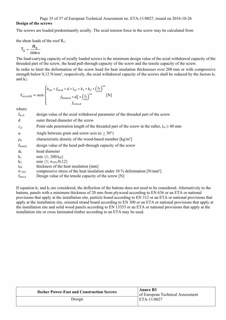
Design of the screws
The screws are loaded predominantly axially. The axial tension force in the screw may be calculated from the shear loads of the roof Rs:
SS
RT
cos
The load-carrying capacity of axially loaded screws is the minimum design value of the axial withdrawal capacity of the threaded part of the screw, the head pull-through capacity of the screw and the tensile capacity of the screw.
In order to limit the deformation of the screw head for heat insulation thicknesses over 200 mm or with compressive strength below 0,12 N/mm², respectively, the axial withdrawal capacity of the screws shall be reduced by the factors k1 and k2:
, ,
∗ , ∗ ∗ ∗ ∗ ∗ρk
350
0,8
, ∗ ∗ρk
350
0,8
,
[N]
where: fax,d design value of the axial withdrawal parameter of the threaded part of the screw
d outer thread diameter of the screw
ef Point side penetration length of the threaded part of the screw in the rafter, lef ≥ 40 mm
Angle between grain and screw axis ( > 30°)
k characteristic density of the wood-based member [kg/m³]
fhead,d design value of the head pull-through capacity of the screw
dh head diameter k1 min {1; 200/tHI} k2 min {1; σ10%/0,12} tHI thickness of the heat insulation [mm] σ 10% compressive stress of the heat insulation under 10 % deformation [N/mm²] ftens,d Design value of the tensile capacity of the screw [N]
If equation k1 and k2 are considered, the deflection of the battens does not need to be considered. Alternatively to the battens, panels with a minimum thickness of 20 mm from plywood according to EN 636 or an ETA or national provisions that apply at the installation site, particle board according to EN 312 or an ETA or national provisions that apply at the installation site, oriented strand board according to EN 300 or an ETA or national provisions that apply at the installation site and solid wood panels according to EN 13353 or an ETA or national provisions that apply at the installation site or cross laminated timber according to an ETA may be used.
Page 36 of 37 of European Technical Assessment no. ETA-11/0027, issued on 2016-10-26
fischer Power-Fast and Construction Screws Annex B4 of European Technical Assessment ETA-11/0027
Design
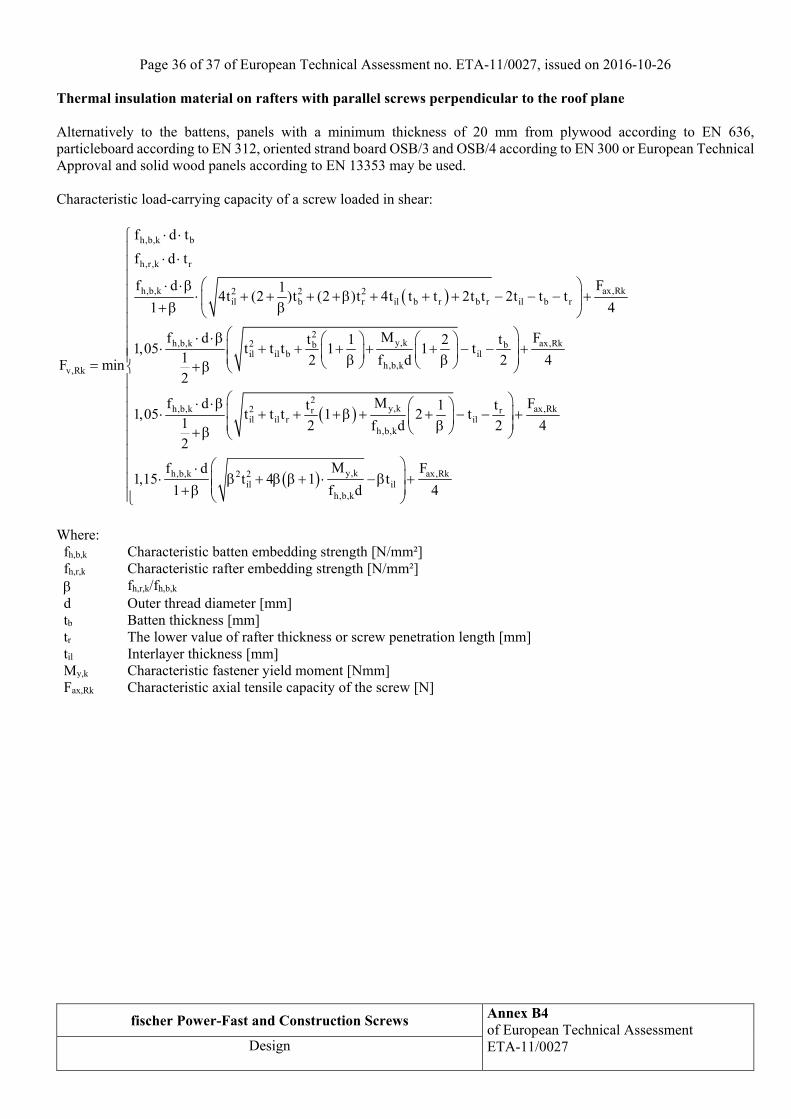
Thermal insulation material on rafters with parallel screws perpendicular to the roof plane Alternatively to the battens, panels with a minimum thickness of 20 mm from plywood according to EN 636, particleboard according to EN 312, oriented strand board OSB/3 and OSB/4 according to EN 300 or European Technical Approval and solid wood panels according to EN 13353 may be used. Characteristic load-carrying capacity of a screw loaded in shear:
h,b,k b
h,r,k r
h,b,k ax,Rk2 2 2il b r il b r b r il b r
2y,kh,b,k ax,Rk2 b b
il il b ilh,b,kv,Rk
f d t
f d t
f d F14t (2 )t (2 )t 4t t t 2t t 2t t t
1 4
Mf d Ft 1 2 t1,05 t t t 1 1 t
1 2 f d 2 4F min2
2y,kh,b,k ax,Rk2 r r
il il r ilh,b,k
y,kh,b,k ax,Rk2 2il il
h,b,k
Mf d Ft 1 t1,05 t t t 1 2 t
1 2 f d 2 42
Mf d F1,15 t 4 1 t
1 f d 4
Where: fh,b,k Characteristic batten embedding strength [N/mm²] fh,r,k Characteristic rafter embedding strength [N/mm²] fh,r,k/fh,b,k d Outer thread diameter [mm] tb Batten thickness [mm] tr The lower value of rafter thickness or screw penetration length [mm] til Interlayer thickness [mm] My,k Characteristic fastener yield moment [Nmm] Fax,Rk Characteristic axial tensile capacity of the screw [N]
Page 37 of 37 of European Technical Assessment no. ETA-11/0027, issued on 2016-10-26
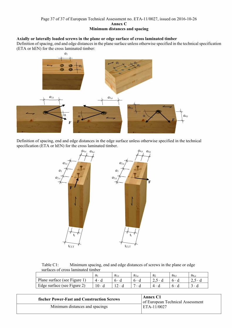
fischer Power-Fast and Construction Screws Annex C1 of European Technical Assessment ETA-11/0027
Minimum distances and spacings
Annex C Minimum distances and spacing
Axially or laterally loaded screws in the plane or edge surface of cross laminated timber Definition of spacing, end and edge distances in the plane surface unless otherwise specified in the technical specification (ETA or hEN) for the cross laminated timber:
Definition of spacing, end and edge distances in the edge surface unless otherwise specified in the technical specification (ETA or hEN) for the cross laminated timber.
Table C1: Minimum spacing, end and edge distances of screws in the plane or edge surfaces of cross laminated timber
a1 a3,t a3,c a2 a4,t a4,c Plane surface (see Figure 1) 4 d 6 d 6 d 2,5 d 6 d 2,5 d Edge surface (see Figure 2) 10 d 12 d 7 d 4 d 6 d 3 d
F a4,t
a4,c
F
a3,c
F
a3,t
a1
a2a2
a2a1
tCLT
F
ti
a3,c
a1
a3,c
a4,c a4,t
tCLT
F
ti
a3,c
a1
a3,t
a4,c a4,c
F