european technical assessment eta-07/0245 of 15/08/2018 · page 3 of 124 of european technical...
TRANSCRIPT

ETA-Danmark A/S Göteborg Plads 1 DK-2150 Nordhavn Tel. +45 72 24 59 00 Fax +45 72 24 59 04 Internet www.etadanmark.dk
Authorised and notified according to Article 29 of the Regulation (EU) No 305/2011 of the European Parliament and of the Council of 9 March 2011
MEMBER OF EOTA
European Technical Assessment ETA-07/0245 of 15/08/2018 I General Part Technical Assessment Body issuing the ETA and designated according to Article 29 of the Regulation (EU) No 305/2011: ETA-Danmark A/S Trade name of the construction product:
SIMPSON STRONG-TIE® Joist End connector
SIMPSON STRONG-TIE® concealed beam hangers Product family to which the above construction product belongs:
Three-dimensional nailing plate (connector for wood to wood connections and wood to concrete or steel connections)
SIMPSON STRONG-TIE A/S Hedegaardsvej 4 – 11, Boulstrup DK-8300 Odder Tel. +45 87 81 74 00 Fax +45 87 81 74 09
Manufacturing plant: SIMPSON STRONG-TIE Manufacturing facilities
This European Technical Assessment contains:
123 pages including 4 annexes which form an integral part of the document
This European Technical Assessment is issued in accordance with Regulation (EU) No 305/2011, on the basis of:
Guideline for European Technical Approval (ETAG) No. 015 Three Dimensional Nailing Plates, April 2013, used as European Assessment Document (EAD).
This version replaces:
The ETA with the same number and issued on 2016-08-10

Page 2 of 124 of European Technical Assessment no. ETA-07/0245, issued on 2018-08-15
Index II SPECIFIC PART OF THE EUROPEAN TECHNICAL ASSESSMENT ..................................................................................4
1 Technical description of product and intended use .............................................................................................................4 2 Specification of the intended use in accordance with the applicable EAD .........................................................................4 3 Performance of the product and references to the methods used for its assessment ...........................................................5
3.1 Mechanical resistance and stability*) (BWR1) ..........................................................................................................5 3.2 Safety in case of fire (BWR2) ......................................................................................................................................5 3.3 Hygiene, health and the environment (BWR3) ..........................................................................................................5 3.7 Sustainable use of natural resources (BWR7) ...........................................................................................................5 3.8 General aspects related to the performance of the product ...................................................................................5 3.9 Mechanical resistance and stability ................................................................................................................................6 3.10 Aspects related to the performance of the product .........................................................................................................6 3.11 General aspects related to the fitness for use of the product ..........................................................................................6
4 Attestation and verification of constancy of performance (AVCP) ....................................................................................7 4.1 AVCP system .................................................................................................................................................................7
5 Technical details necessary for the implementation of the AVCP system, as foreseen in the applicable EAD .................7 Annex A Revision History ...................................................................................................................................................................8 Annex B Typical Installation .............................................................................................................................................................10
B.1 Concealed joist hangers typical installation ......................................................................................................................10 B.2 Typical Installation for ETB, EL, ELS .............................................................................................................................11 B.3 Typical Installation of ICS and ICST: ..............................................................................................................................17 B.4 Typical installation of ETS/ETSN ....................................................................................................................................17 B.5 Typical Installation of ATFN ...........................................................................................................................................21 B.6 Installation for fire justification ........................................................................................................................................23
Annex C Design ...........................................................................................................................................................................27 C.1 Basis of Design .................................................................................................................................................................27 C.2 Definition of force directions ............................................................................................................................................29 C.3 Fastener specification and capacities ................................................................................................................................34
Annex D- Product definition and capacities .................................................................................................................................36 D1 Concealed joist hanger BTN, BT4, BTALU, BTx ...........................................................................................................36 Figure D1-1: Dimension drawing of concealed joist hangers ........................................................................................................36 D2 Concealed joist hanger TU, TUB, TUS, TUBS ................................................................................................................74 D3 Concealed joist hanger ETNM .........................................................................................................................................83 D4 Concealed joist hanger BTCx ...........................................................................................................................................86 D5 ICS ....................................................................................................................................................................................91 D6 ETB ...................................................................................................................................................................................94 D7 EL .....................................................................................................................................................................................96 D8 ELS ...................................................................................................................................................................................99 D9 CBH ................................................................................................................................................................................101 D10 ETS / ETSN ....................................................................................................................................................................106 D11 ICST ................................................................................................................................................................................110 D12 Janebo : JHHU, JHDU, JHGU .......................................................................................................................................112 D13 ATFN ..............................................................................................................................................................................122

Page 3 of 124 of European Technical Assessment no. ETA-07/0245, issued on 2018-08-15
Translations of this European Technical Assessment in other languages shall fully correspond to the original issued document and should be identified as such. Communication of this European Technical Assessment, including transmission by electronic means, shall be in full (excepted the confidential Annex(es) referred to above). However, partial reproduction may be made, with the written consent of the issuing Technical Assessment Body. Any partial reproduction has to be identified as such.
Page 4 of 124 of European Technical Assessment no. ETA-07/0245, issued on 2018-08-15
II SPECIFIC PART OF THE EUROPEAN TECHNICAL ASSESSMENT
1 Technical description of product and intended use
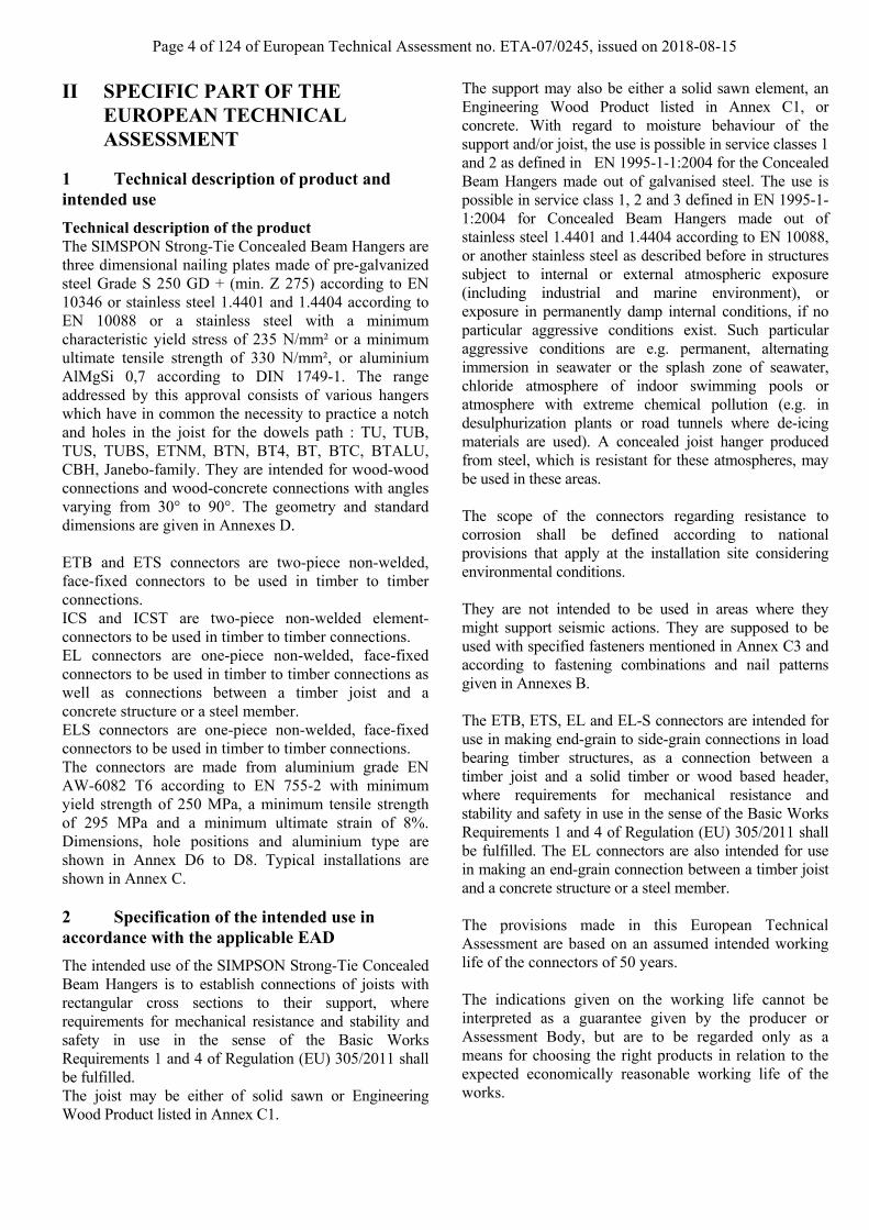
Technical description of the product The SIMSPON Strong-Tie Concealed Beam Hangers are three dimensional nailing plates made of pre-galvanized steel Grade S 250 GD + (min. Z 275) according to EN 10346 or stainless steel 1.4401 and 1.4404 according to EN 10088 or a stainless steel with a minimum characteristic yield stress of 235 N/mm² or a minimum ultimate tensile strength of 330 N/mm², or aluminium AlMgSi 0,7 according to DIN 1749-1. The range addressed by this approval consists of various hangers which have in common the necessity to practice a notch and holes in the joist for the dowels path : TU, TUB, TUS, TUBS, ETNM, BTN, BT4, BT, BTC, BTALU, CBH, Janebo-family. They are intended for wood-wood connections and wood-concrete connections with angles varying from 30° to 90°. The geometry and standard dimensions are given in Annexes D. ETB and ETS connectors are two-piece non-welded, face-fixed connectors to be used in timber to timber connections. ICS and ICST are two-piece non-welded element-connectors to be used in timber to timber connections. EL connectors are one-piece non-welded, face-fixed connectors to be used in timber to timber connections as well as connections between a timber joist and a concrete structure or a steel member. ELS connectors are one-piece non-welded, face-fixed connectors to be used in timber to timber connections. The connectors are made from aluminium grade EN AW-6082 T6 according to EN 755-2 with minimum yield strength of 250 MPa, a minimum tensile strength of 295 MPa and a minimum ultimate strain of 8%. Dimensions, hole positions and aluminium type are shown in Annex D6 to D8. Typical installations are shown in Annex C. 2 Specification of the intended use in accordance with the applicable EAD
The intended use of the SIMPSON Strong-Tie Concealed Beam Hangers is to establish connections of joists with rectangular cross sections to their support, where requirements for mechanical resistance and stability and safety in use in the sense of the Basic Works Requirements 1 and 4 of Regulation (EU) 305/2011 shall be fulfilled. The joist may be either of solid sawn or Engineering Wood Product listed in Annex C1.
The support may also be either a solid sawn element, an Engineering Wood Product listed in Annex C1, or concrete. With regard to moisture behaviour of the support and/or joist, the use is possible in service classes 1 and 2 as defined in EN 1995-1-1:2004 for the Concealed Beam Hangers made out of galvanised steel. The use is possible in service class 1, 2 and 3 defined in EN 1995-1-1:2004 for Concealed Beam Hangers made out of stainless steel 1.4401 and 1.4404 according to EN 10088, or another stainless steel as described before in structures subject to internal or external atmospheric exposure (including industrial and marine environment), or exposure in permanently damp internal conditions, if no particular aggressive conditions exist. Such particular aggressive conditions are e.g. permanent, alternating immersion in seawater or the splash zone of seawater, chloride atmosphere of indoor swimming pools or atmosphere with extreme chemical pollution (e.g. in desulphurization plants or road tunnels where de-icing materials are used). A concealed joist hanger produced from steel, which is resistant for these atmospheres, may be used in these areas. The scope of the connectors regarding resistance to corrosion shall be defined according to national provisions that apply at the installation site considering environmental conditions. They are not intended to be used in areas where they might support seismic actions. They are supposed to be used with specified fasteners mentioned in Annex C3 and according to fastening combinations and nail patterns given in Annexes B. The ETB, ETS, EL and EL-S connectors are intended for use in making end-grain to side-grain connections in load bearing timber structures, as a connection between a timber joist and a solid timber or wood based header, where requirements for mechanical resistance and stability and safety in use in the sense of the Basic Works Requirements 1 and 4 of Regulation (EU) 305/2011 shall be fulfilled. The EL connectors are also intended for use in making an end-grain connection between a timber joist and a concrete structure or a steel member. The provisions made in this European Technical Assessment are based on an assumed intended working life of the connectors of 50 years. The indications given on the working life cannot be interpreted as a guarantee given by the producer or Assessment Body, but are to be regarded only as a means for choosing the right products in relation to the expected economically reasonable working life of the works.

Page 5 of 124 of European Technical Assessment no. ETA-07/0245, issued on 2018-08-15
3 Performance of the product and references to the methods used for its assessment
Characteristic
Assessment of characteristic
3.1 Mechanical resistance and stability*) (BWR1)
Characteristic load-carrying capacity
See Annex D
Stiffness
No performance assessed
Ductility in cyclic testing
No performance assessed
3.2 Safety in case of fire (BWR2)
Reaction to fire
SIMPSON Strong-Tie Concealed Beam Hangers and Joist End connectors are classified as Euro class A1 in accordance with EN 13501-1 and EC decision 96/603/EC, amended by EC Decision 2000/605/EC
3.3 Hygiene, health and the environment (BWR3)
Influence on air quality
The product does not contain/release dangerous substances specified in TR 034, dated March 2012**)
3.7 Sustainable use of natural resources (BWR7)
No Performance Determined
3.8 General aspects related to the performance of the product
The SIMPSON Strong-Tie Concealed Beam Hangers and Joist End connectors have been assessed as having satisfactory durability and serviceability when used in timber structures using the timber species described in Eurocode 5 and subject to the conditions defined by service class 1, 2 and 3
Identification
See Annex A
*) See additional information in section 3.9 – 3.12. **) In addition to the specific clauses relating to dangerous substances contained in this European technical Assessment, there may be other requirements applicable to the products falling within its scope (e.g. transposed European legislation and national laws, regulations and administrative provisions). In order to meet the provisions of the Construction Products Regulation, these requirements need also to be complied with, when and where they apply.

Page 6 of 124 of European Technical Assessment no. ETA-07/0245, issued on 2018-08-15
3.9 Mechanical resistance and stability
See annex D for characteristic load-carrying capacities of the SIMPSON Strong-Tie Concealed Beam Hangers and SIMPSON Strong-Tie Joist End connectors. The mechanical capacities of the concealed beam hangers and Joist End connectors are determined by calculation assisted by testing as described in the EOTA Guideline 015 clause 5.1.2. They should be used for designs in accordance with EN-1995-1-1 (Eurocode 5) or a similar national timber code. The load-bearing capacities given in Annexes D of the concealed beam hangers and Joist End connectors have been determined based on the use of connector nails or 4.0 x 60 in accordance to ETA-04/0013 and screws are described in Annex C3. It is allowed to use connector screws or connector nails 4.0 x 50 or 4.2 x 50 or 4.2 x 60 in accordance to ETA-04/0013. Case by case calculations have to be carried out to determine the load-bearing capacity of the connection. The design also allows the use of threaded nails in accordance to EN 14592 with a diameter in the range 4.0-4.2 mm and a minimum length of 35 mm, assuming a thick steel plate when calculating the lateral nail load-bearing capacity. If no calculations are made a reduction factor equal to the ratio between the characteristic withdrawal capacity of the actual used threaded nail and the characteristic withdrawal capacity of the corresponding connector nail according to table B1 in ETA-04/0013 is applicable for all load-bearing capacities of the connection. No performance has been determined in relation to ductility of a joint under cyclic testing. The contribution to the performance of structures in seismic zones, therefore, has not been assessed 3.10 Aspects related to the performance of the
product
3.10.1 Corrosion protection in service class 1, 2 and 3. The thickness of galvanisation (Z275 according to EN 10143) or the aluminium AlMgSi 0,7 is such that a reasonable durability may be expected in service classes 1 and 2 according to EN 1995-1-1:2004, in the conditions stated in 1.1 above. ZM310 can be used as corrosion protection in service class 3 (applicable for all steel thicknesses). The use of stainless steel 1.4401 and 1.4404 according to EN 10088 extends the scope to service class 3 according to EN 1995-1-1:2004 in the conditions stated in 1.1 above.
The ETB, ETS, EL and EL-S connectors have been assessed as having satisfactory durability and serviceability when used in timber structures using the timber species described in Eurocode 5 and subject to the conditions defined by service class 1 and 2 The ATFN connectors have been assessed as having satisfactory durability and serviceability when used in timber structures using the timber species described in Eurocode 5 and subject to the conditions defined by service class 1 Serviceability of the Concealed Beam Hangers is understood as their ability to resist loads without unacceptable deformations. 3.11 General aspects related to the fitness for use of the product
Concealed Beam Hangers and Joist End connectors are manufactured in accordance with the provisions of this European Technical Assessment using the manufacturing processes as identified in the inspection of the plant by the notified inspection body and laid down in the technical documentation. SIMPSON Strong-Tie Concealed Beam Hangers and Joist End connectors shall be installed on the basis of a specific structural design for each installation, using the load-bearing capacities given in Annexes D and applying the appropriate kmod factor depending on the relevant service class / load duration and the appropriate National partial safety factor for materials. The fixing of the Concealed Beam Hangers and Joist End connectors to the support shall use the appropriate nails or screws in case of solid wood or wood-based support, appropriate CE marked metal anchors for use in concrete in case of concrete support. The load bearing capacities indicated in the Annexes are given provided that the fixing device has been appropriately designed and installed. The Concealed Beam Hangers shall be installed by appropriately qualified personnel, following an installation plan and relevant construction details worked out for each individual building project. The installation plan shall be based on the manufacturers general guide and provisions for installing SIMPSON Strong-Tie connections
Page 7 of 124 of European Technical Assessment no. ETA-07/0245, issued on 2018-08-15
4 Attestation and verification of constancy of performance (AVCP)
4.1 AVCP system
According to the decision 97/638/EC of the European Commission1, as amended, the system(s) of assessment and verification of constancy of performance (see Annex V to Regulation (EU) No 305/2011) is 2+. 5 Technical details necessary for the implementation of the AVCP system, as foreseen in the applicable EAD
Technical details necessary for the implementation of the AVCP system are laid down in the control plan deposited at ETA-Danmark prior to CE marking
Issued in Copenhagen on 2018-08-15 by
Thomas Bruun Managing Director, ETA-Danmark
Page 8 of 124 of European Technical Assessment no. ETA-07/0245, issued on 2018-08-15
Annex A Revision History
Revision History
Issue update
3
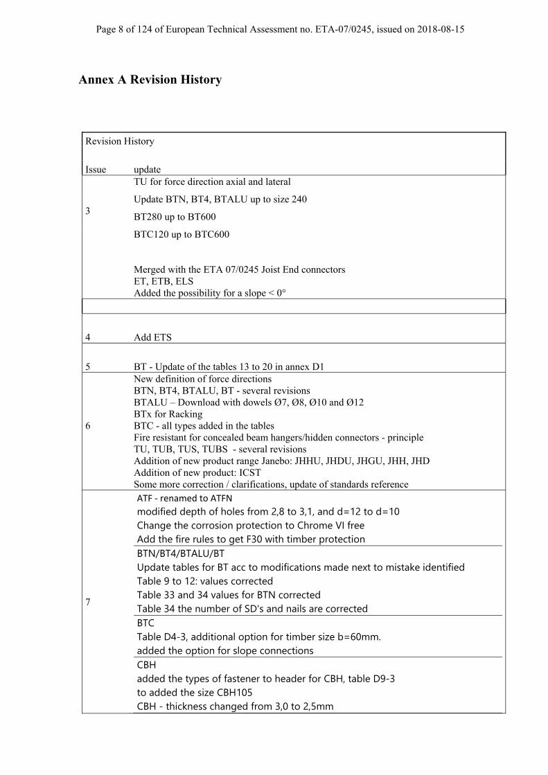
TU for force direction axial and lateral
Update BTN, BT4, BTALU up to size 240
BT280 up to BT600
BTC120 up to BTC600
Merged with the ETA 07/0245 Joist End connectors ET, ETB, ELS Added the possibility for a slope < 0°
4 Add ETS
5 BT - Update of the tables 13 to 20 in annex D1
6
New definition of force directions BTN, BT4, BTALU, BT - several revisions BTALU – Download with dowels Ø7, Ø8, Ø10 and Ø12 BTx for Racking BTC - all types added in the tables Fire resistant for concealed beam hangers/hidden connectors - principle TU, TUB, TUS, TUBS - several revisions Addition of new product range Janebo: JHHU, JHDU, JHGU, JHH, JHD Addition of new product: ICST Some more correction / clarifications, update of standards reference
7
ATF ‐ renamed to ATFN
modified depth of holes from 2,8 to 3,1, and d=12 to d=10 Change the corrosion protection to Chrome VI free Add the fire rules to get F30 with timber protection BTN/BT4/BTALU/BT Update tables for BT acc to modifications made next to mistake identified Table 9 to 12: values corrected Table 33 and 34 values for BTN corrected Table 34 the number of SD's and nails are corrected BTC Table D4-3, additional option for timber size b=60mm. added the option for slope connections CBH added the types of fastener to header for CBH, table D9-3 to added the size CBH105 CBH - thickness changed from 3,0 to 2,5mm

Page 9 of 124 of European Technical Assessment no. ETA-07/0245, issued on 2018-08-15
Janebo correct a typing error in the formula (the index 2 in the box shall be 4) added the product names/sizes for types without uplift hook Correction of some typing errors. to add additional coatings: Z800 and ZM310

Page 10 of 124 of European Technical Assessment no. ETA-07/0245, issued on 2018-08-15
Annex B Typical Installation
B.1 Concealed joist hangers typical installation
header
joist BT
4-row 2-row 4-row 2-rowcolumn column
Nail Pattern
Other nail pattern is described in annex D. Concealed joist hangers (“BT” in the following text)
A BT connection is deemed fit for its intended use under following conditions:
1. BT can be fastened to wood-based members by nails or screws.
2. There shall be nails or screws in all holes or a partial nailing pattern as shown in Annex A and prescribed in Annex B can be used.
3. The characteristic capacity of the BT connection is calculated according to the manufacturer’s technical documentation.
4. The concealed Joist Hangers connection is designed in accordance with Eurocode 5 or an appropriate National Code.
5. The thickness of the beam shall be at least l, where l is the length of the fasteners in the beam. This is in accordance with Eurocode 5.
6. The depth of the Joist shall be so large that the steel dowel has at least a distance of 3d to the edge, where d = the diameter of the steel dowel.
7. The depth of the beam shall be so large that the fasteners have at least a distance according EN 1995-1-1, in relation to the force direction.
slo
t
dowelHb
b N
Nh
header
joist

Page 11 of 124 of European Technical Assessment no. ETA-07/0245, issued on 2018-08-15
8. The slot for the BT in the joist may be t +1/ +2 mm , where t = the thickness of the bar of the BT, for the type TU12, TUS12, TUB12 and TUBS12 the slot may be 6 mm, for the other size of type TU, TUS, TUB and TUBS the slot may be 9-10mm
9. For connection to concrete the anchor bolts shall be mounted according to the approval of the used anchor bolt
10. For connection to steel the bolts shall be mounted according the relevant standard
11. The backside of the BT shall have contact along the full height of the connector.
12. BT made from stainless steel shall only be fastened with fasteners made from suitable stainless steel. Zinc-coated concealed joist hangers shall not be fastened with fasteners of stainless steel.
13. Nails or screws to be used shall have a diameter, which fits to the holes of the BTs. They shall have a diameter which is not smaller than the diameter of the hole minus 1 mm.
14. The execution of the connection shall be in accordance with the approval holder’s technical literature.
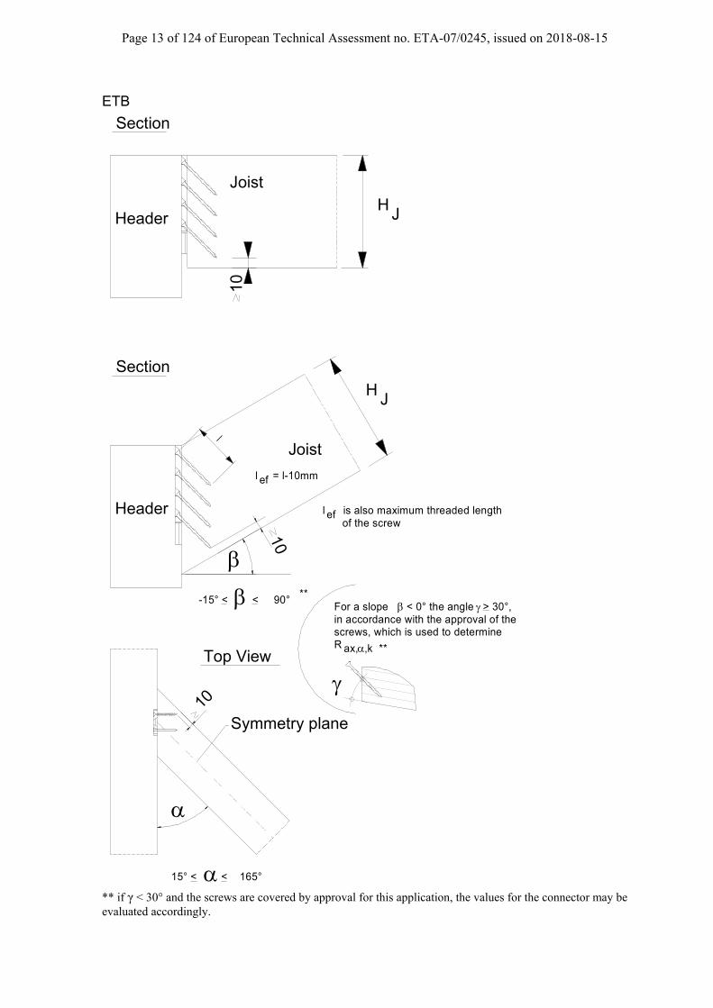
B.2 Typical Installation for ETB, EL, ELS
ETB EL ELS
The connection to the header or the column for the ETB and ELS can be made with Nails or CSA screws and screws only for Type EL. The connection to the end grain of the joist is made with screws Ø5 mm according to the corresponding Annex. The angle between the Joist End connector and the screws is 45°. A slope and a skew is possible in these product ranges.
An ETB, EL and EL-S connection is deemed fit for its intended use provided:
1. The header shall be restrained against rotation. 2. If the connection only has a connector on one side of the header, the eccentricity moment from the
joists shall be considered when verifying the strength of the header. 3. For a header with joists from both sides but with different reaction forces a similar consideration
applies. 4. There shall be nails or screws in all holes or a partial nailing pattern as prescribed in Annex D. 5. For EL connectors fastened to timber frame members as shown in arrangement 1 (see following), only
the thread length in the timber member may be taken into account. 6. For EL connectors fastened to timber frame members as shown in arrangement 2 (see following), the
sheathing (e.g. OSB) must be flush with the header surface. 7. The gap between the side grain of the header and the vertical flap of the hanger shall be limited.
The gap between the side grain of the header and the vertical flap of the connector shall be maximum 3 mm for connections made with the EL connector. For connections made with the ETB and ELS connectors the gap between the member surface and the connector shall be maximum 1 mm.
8. The EL connector shall be in close contact with the concrete or steel over the horizontal flap. 9. For ETB and EL-S connectors the width of the header shall be at least l+4d, where l is the length and d
is the diameter of the nails or screws in the header.

Page 12 of 124 of European Technical Assessment no. ETA-07/0245, issued on 2018-08-15
10. For ETB, EL and EL-S connectors the depth of the joist shall allow an edge distance of at least 10 mm between the screw tip and the adjacent joist surface.
11. The header shall have a plane surface against the whole ETB, EL or EL-S connector. 12. Nails or screws to be used shall have a diameter, which fits the holes of the ETB, EL and EL-S
connectors. 13. Minimum end and edge distance for the nails/screws have to be observed according to the standard or,
if applicable, according to the relevant assessment of the fastener.
Page 13 of 124 of European Technical Assessment no. ETA-07/0245, issued on 2018-08-15
ETB
l
l = l-10mmef
l is also maximum threaded length efof the screw
Joist
Symmetry plane
10
10
HJ
15° < < 165°
Joist
10
HJ
-15° < < 90° **
Top View
Section
Section
in accordance with the approval of the screws, which is used to determineR ax, ,k **
For a slope < 0° the angle > 30°,
Header
Header
** if γ < 30° and the screws are covered by approval for this application, the values for the connector may be evaluated accordingly.
Page 14 of 124 of European Technical Assessment no. ETA-07/0245, issued on 2018-08-15
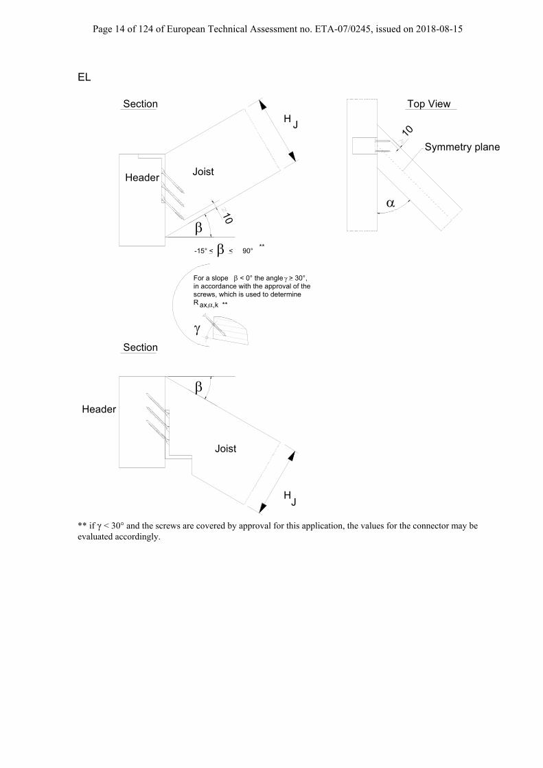
EL
Joist
Symmetry plane
10
10
HJ
Joist
HJ
**-15° < < 90°
Top ViewSection
Section
in accordance with the approval of the screws, which is used to determineR ax, ,k **
For a slope < 0° the angle > 30°,
Header
Header
** if γ < 30° and the screws are covered by approval for this application, the values for the connector may be evaluated accordingly.

Page 15 of 124 of European Technical Assessment no. ETA-07/0245, issued on 2018-08-15
Installations
<10
~10
sheathing e.g. OSB
sheathing e.g. OSB
Arrangement 1 Arrangement 2
fastened to timber frame members
without any embedding
embed in the header and the front of joistembed in the header
Page 16 of 124 of European Technical Assessment no. ETA-07/0245, issued on 2018-08-15
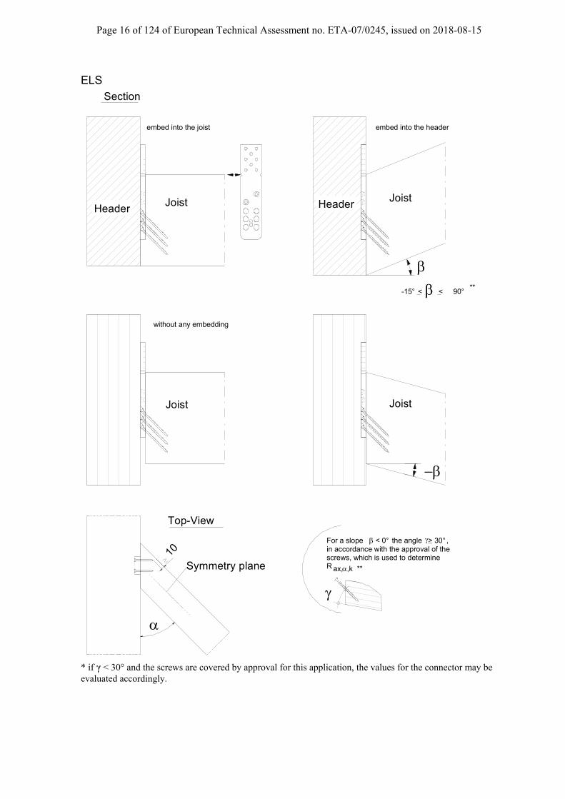
ELS
-15° < < 90°
**
10
Symmetry plane
Top-View
in accordance with the approval of the screws, which is used to determineR ax, ,k **
For a slope < 0° the angle > 30° ,
Section
Joist Joist
JoistJoist
without any embedding
embed into the headerembed into the joist
Header Header
* if γ < 30° and the screws are covered by approval for this application, the values for the connector may be evaluated accordingly.

Page 17 of 124 of European Technical Assessment no. ETA-07/0245, issued on 2018-08-15
B.3 Typical Installation of ICS and ICST:
ICS A 12 mm deep pocket is necessary in each timber element before installing the ICS male and female part. The characteristic capacities given below are only available when the ICS are installed in these pockets. The ICS male part needs to be fixed on the face of the timber element, on top of the 12 mm deep and 40 mm wide pocket as shown below. The pocket must continue at least 80 mm below the male part in order to connect the 2 parts The ICS female part needs to be fixed in the back of the 12 mm deep and 80 mm wide pocket as shown below. The pocket must continue at least 80 mm above the female part in order to connect the 2 parts.
ICST Routing is necessary on 1 side only. This routing should be 15 mm deep, 90 mm wide and 220 mm long as a minimum. The distance between the ICST and the end of the timber elements should be 100 mm as a minimum. ICST is composed of two parts, which will be face to face in final position. The guiding central part of the connector facilitates the timber assembly. The ICST connector is intended in the case of “closed” walls (installation of exterior and interior wall coverings).
9015
220
F3F4
B.4 Typical installation of ETS/ETSN

Page 18 of 124 of European Technical Assessment no. ETA-07/0245, issued on 2018-08-15
The connection to the header for the ETS can be only made with CSA screws. For ETS: The connection to the end grain of the joist is made with screws Ø5 mm according to the corresponding Annex. The angle between the Joist End connector and the screws is 45°. For ETSN: The connection to the end grain of the joist is made with washer head screws Ø6 mm according to the corresponding Annex. A slope and a skew is possible in these product ranges.
An ETS/ETSN connection is deemed fit for its intended use provided:
1. The header shall be restrained against rotation. 2. If the connection only has a connector on one side of the header, the eccentricity moment from the joists
shall be considered when verifying the strength of the header. 3. For a header with joists from both sides but with different reaction forces a similar consideration applies. 4. For ETS, there shall be screws in all tab-aperture, filling the additional Ø5 mm hole is optional. For
ETSN, there shall be one screw for each fastener alignment guide composed of a tab-aperture and an oblong hole.
5. For connections made with the ETS/ETSN connectors the gap between the member surface and the connector shall be maximum 1 mm.
6. For ETS connectors the width of the header shall be at least l+4d, where l is the length and d is the diameter of the nails or screws in the header.
7. For ETS connectors the depth of the joist shall allow an edge distance of at least 10 mm between the screw tip and the adjacent joist surface.
8. For ETSN connectors the depth of the joist shall allow an edge distance of at least 8 mm (for ETSN100) & 10 mm (for ETSN130 & ETSN180) between the screw tip and the adjacent joist surface.
9. The header shall have a plane surface against the whole ETS / ETSN connector. 10. Screws to be used shall have a diameter, which fits the holes of the ETS connectors.

Page 19 of 124 of European Technical Assessment no. ETA-07/0245, issued on 2018-08-15
ETS / ETSN The header must be routed as described below.
Model Dimensions of the routing
A (mm) B (mm) C (mm) ETS100 100 65 12 ETS140 140 65 12 ETS180 180 75 12 ETSN100 100 60 12 ETSN130 130 65 12 ETSN180 180 75 12

Page 20 of 124 of European Technical Assessment no. ETA-07/0245, issued on 2018-08-15
l = l-10mmef
l is also maximum threaded length efof the screw
Joist
Symmetry plane
1010
HJ
**
in accordance with the approval of the screws, which is used to determineR ax, ,k **
For a slope < 0° the angle > 30° ,
Top View
Section
15° < < 165°
-15° (-25° ) < < 90°
l
Header
ETS (ETSN)
** if γ < 30° and the screws are covered by approval for this application, the values for the connector may be evaluated accordingly.
Page 21 of 124 of European Technical Assessment no. ETA-07/0245, issued on 2018-08-15
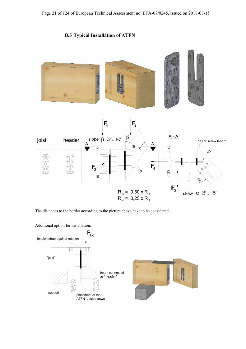
B.5 Typical Installation of ATFN
1F1F
35° ... 145°
4FF3
25° ... 155°
A - A
A A
4R = 0,25 x R1
3R = 0,50 x R13
a a
10
15
10
joist header
2525
15
15
slope
skew
1/3 of screw length
The distances to the border according to the picture above have to be considered. Additional option for installation:
tension strap against rotation 1,dF
beam connected
"joist"
as "header"
placement of the ATFN upside down
support

Page 22 of 124 of European Technical Assessment no. ETA-07/0245, issued on 2018-08-15
1,dF
Header columnwith joist plate
Edge beam with header plate. The beam shall be secured against twisting
support The routing can be made a) in the joist with 10mm, b) in the header with 10mm, or c) in both parts with together ≤ 10mm.
The connection to the header can be made with nails in the case where the header is prevented from rotation. In other cases, the CSA screws have to be installed.
- F < 0,2 x F 1r
F 1l 1l
F 1l 1r
F 1
F
1.kR
F 1l 1r
F
- F > 0,2 x F 1r
F 1l 1l
1F
R 1.k
eHeader is prevented for rotation Header is free to rotate
Page 23 of 124 of European Technical Assessment no. ETA-07/0245, issued on 2018-08-15
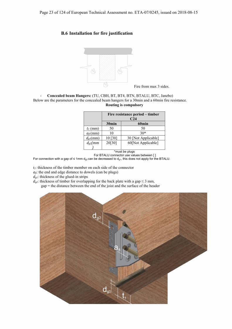
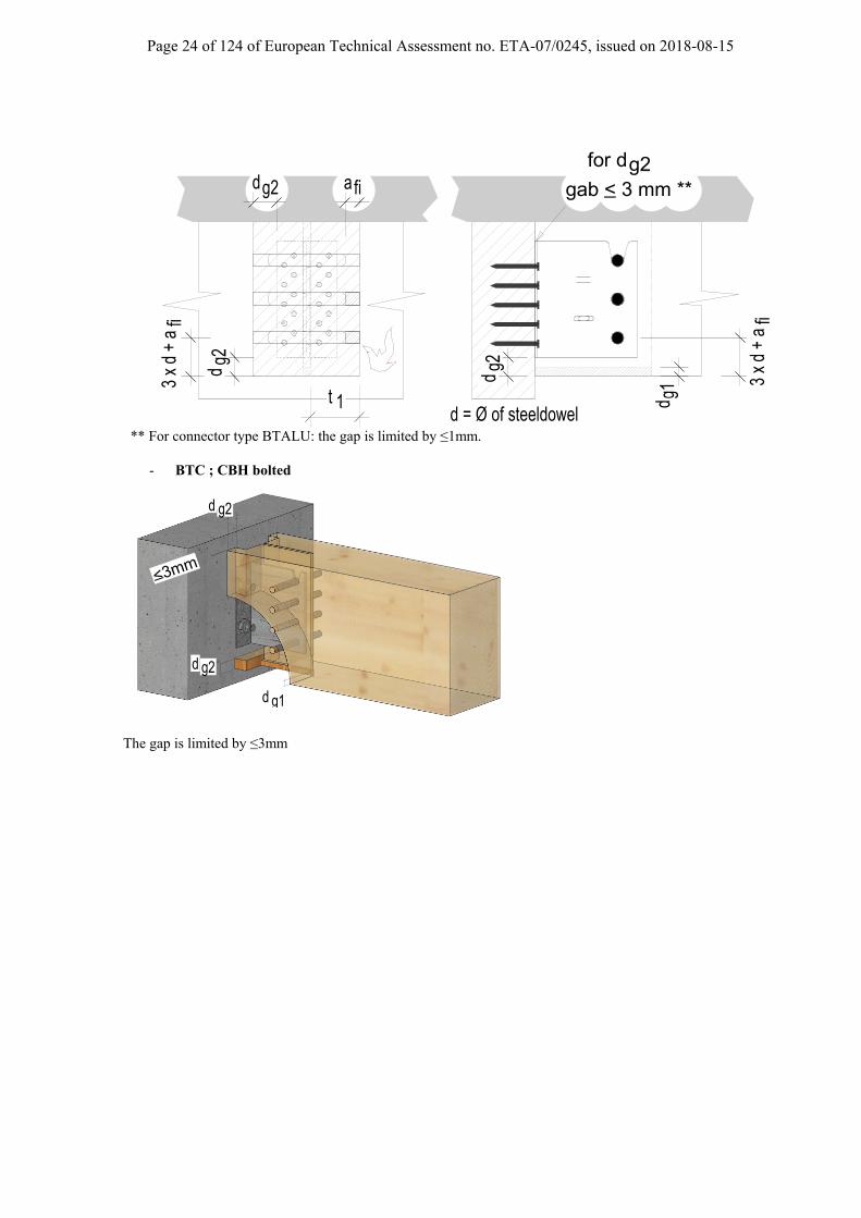
B.6 Installation for fire justification
Fire from max 3 sides.
- Concealed beam Hangers: (TU, CBH, BT, BT4, BTN, BTALU, BTC, Janebo) Below are the parameters for the concealed beam hangers for a 30min and a 60min fire resistance.
Routing is compulsory
Fire resistance period – timber C24
30min 60min t1 (mm) 50 50 afi(mm) 10 30* dg1(mm) 10 [30] 30 [Not Applicable] dg2(mm
)20[30] 60[Not Applicable]
*must be plugs For BTALU connector use values between [ ]
For connection with a gap of ≤ 1mm dg2 can be decreased to dg1, this does not apply for the BTALU.
t1: thickness of the timber member on each side of the connector afi: the end and edge distance to dowels (can be plugs) dg1: thickness of the glued-in strips dg2: thickness of timber for overlapping for the back plate with a gap ≤ 3 mm, gap = the distance between the end of the joist and the surface of the header
Page 24 of 124 of European Technical Assessment no. ETA-07/0245, issued on 2018-08-15
afig2d
g2d
3 x
d +
afi
g1d
3 x
d +
afi
gab < 3 mm **_
t 1d = Ø of steeldowel
for dg2
g2d
** For connector type BTALU: the gap is limited by ≤1mm.
- BTC ; CBH bolted
The gap is limited by ≤3mm
g1
g2d
<3mm_
g2d
d

Page 25 of 124 of European Technical Assessment no. ETA-07/0245, issued on 2018-08-15
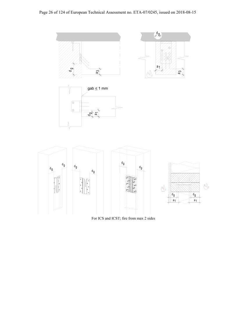
- Hidden connector : (ATFN, ETB, ETS, EL/ELS, ICS, ICST)
Hidden connectors such as ATFN, ETB, ETS, and EL/ELS, ICS, ICST can also be justified by using this solution. In this case, a routing is compulsory. A thickness of timber dg on each side of the connector must be respected.
Fire resistance period – timber C24
30min 60min
dg(mm)
ETS/ETSN ICS, ICST
10 30
ATFN, ETB, EL/ELS 30 - ICS, ICST 10 30
a1(mm)ETS, ETSN,
40 55 ICS, ICST
ATFN, EL/ELS, ETB 40 -
a3(mm)ETS, ETSN, 28 58
ATFN, EL/ELS, ETB 28 -
dg: thickness of the timber protection a1: edge distance of the axis of the fastener a3: edge distance of the point of the fastener The protection of the top of the connector is made with the deck, a timber element, or other protective materials.
Page 26 of 124 of European Technical Assessment no. ETA-07/0245, issued on 2018-08-15
gd
gd
gd
gab < 1 mm_
1a
1a
3a
3a
gd
1a
dg
a 1
gdgd
gdgdgd
gd
For ICS and ICST; fire from max 2 sides

Page 27 of 124 of European Technical Assessment no. ETA-07/0245, issued on 2018-08-15
Annex C Design
C.1 Basis of Design
Characteristic capacities of the concealed joist hangers with nails or screws.
The formulas are applicable for connectors made from stainless steel with a characteristic yield stress of at least 235 Mpa or a characteristic ultimate tensile strength of at least 330 Mpa and for ordinary steel of the quality S250GD + Z275 according to EN 10346 or S235JR according to EN10025, or aluminium AlMgSi 0,7 to DIN 1749-1.
The Joist End connectors are made from aluminium grade EN AW-6082 T6 according to EN 755-2 with minimum yield strength of 250 MPa, a minimum tensile strength of 295 MPa and a minimum ultimate strain of 8 %. The ATFN connector is made from: Plates; S355MC according to EN10149 Pins: steel with a minimum yield strength of 580N/mm² a minimum tensile strength of 610 N/mm² and a minimum ultimate strain of 16%. The pins are connected with the plates by compression strain
Requirements for the header or the joist for the concealed beam hangers:
- The wood members can be of solid timber, glued laminated timber and similar glued members, or wood-based structural members.
- The requirements of the wood members can be fulfilled by using the following materials: - Solid timber classified to C24 or better according to EN 338 - Glued members of timber classified to C24 or better according to EN 338 when structural adhesives
are used. - Glued laminated timber classified to GL24c or better according to EN 1194. - Solid Wood Panels, SWP according to EN 13353. - Laminated Veneer Lumber LVL according to EN 14374 - Plywood according to EN 636 - Other Engineering Wood products classified for their resistance and with certified mechanical
performances for fasteners The characteristic density of the wood members shall be at least 350 kg/m3. Lower densities are applicable but the load bearing capacities shall be reduced by the kdens factor, given by
2
350
k
densk
Where ρk is the characteristic density of the timber in kg/m3. In case of concrete support, concrete shall be specified according to EN 206-1 with a resistance class within the following range : C20/25 to C50/60. The wood members shall have a thickness which is larger than the penetration depth of the fasteners into the members
Requirements for the header or the joist for the Joist End connectors:
For screws or nails in the end grain of the wood (joist) the requirement to the material of the wood members can be fulfilled by using the following materials:
- Solid timber classified to C14-C40 according to EN 338 / EN 14081, - Glued members of timber classified to GL24c or better according to EN 1194 / EN 14080, - Solid Wood Panels, SWP according to EN 13353,

Page 28 of 124 of European Technical Assessment no. ETA-07/0245, issued on 2018-08-15
For nailing in the side of the wood members (header) the requirement to the wood members can be fulfilled by using the following materials:
- Solid timber classified to C14-C40 according to EN 338 / EN 14081, - Glued members of timber classified C14-C40 according to EN 338 / EN 14081 when structural adhesives
are used. - Glued members of timber classified to GL24c or better according to EN 1194 / EN 14080, - Solid Wood Panels, SWP according to EN 13353, - Laminated Veneer Lumber LVL according to EN 14374, - Parallam PSL, - Laminated Strand Lumber LSL e.g. Parallam PSL and Timber Strand, - Oriented Strand Board OSB according to EN 300 - Duo- and Triobalken, - Layered wood plates, - Plywood according to EN 636 - For EWP (Engineered Wood Products), please refer to the manufacturer’s specifications.
The load-carrying formulas stated in Annex B are applicable for a wood density from 290 kg/m3 to 460 kg/m3. It is allowed to use wood with a density up to 500 kg/m3. However, increased load-carrying capacity than that for a density of 460 kg/m3 should not be employed. For density between 420 and 500 kg/m3 pre-drilling of nail and screw holes are necessary.

Page 29 of 124 of European Technical Assessment no. ETA-07/0245, issued on 2018-08-15
C.2 Definition of force directions
The characteristic load-carrying capacities are for the following force directions:
F1 Downward F2 Uplift F3 Lateral – horizontal F4 Axial in the middle of the beam
Concealed joist hangers type BTN, BT4, BTALU, BTx, BTCx
Force direction F1 : These are given in different tables for each connection. “Table for connection with header free from rotation”. Here it is assumed, that the connection has a BT both sides of the header and the difference between the active forces is no more than 20%, or the header is clamped. In this case the calculation for the header may be made separately. “Table for connection with header free to rotate”. Here the eccentricity of the BT is used so the moment is absorbed in the BT – connection. For the capacity for the header with b = 240 mm it is to multiply the values for bHT = 180mm with the factor 0,77. For an uplift force, the upper dowel in the cut-out hole may not be used for the calculation. Force direction F2 : The values for F1 can be used where the number of steel dowel has to reduce by the upper one in the “cut-out” hole. How to use the tables:
Force direction nail patternthe used fastener and size
length of steeldowel
CNA 4,0x50 4-row
nN [kN] nN [kN]
number of 20 18,2 20 19,4steel dowel 44 32,2 44 34,5
28 29,5 28 31,248 43,0 52 46,136 41,9 36 44,356 53,9 60 57,6
capacity for the nails/steel dowelnumber of nails
4
5
80 100Length SD [mm]
R1,k
number of SD
3
Sample: a connection with a BT with 4 Steel dowel with a length of 100mm, the width of joist is min. 100mm, nail pattern = 4-row, and 28 nails 4,0x50 is R1,k = 31,2 kN. for the same connection with 52 nails R1,k = 46,1 kN.
1F 2
F
4F 3
F

Page 30 of 124 of European Technical Assessment no. ETA-07/0245, issued on 2018-08-15
For using another number of nails, it must be between the number of fasteners listed in the table, the capacity may be determined by linear interpolation based on the number of nails. In the sample before the number of nails may be between 28 and 52.
1F
placing of thenails accordingto the drawing
placing of the
to the drawingdowels according
Force direction F3 : These are given in the table, with and without screws. For connections with screws, the screws are inserted perpendicular next to the BT, see following picture. The screws for reinforcement of the joist shall have a length < the width of the joist. The assumed length for the tables in Annex B is width of the joist -20mm. The screws are inserted from both sides. The screws shall be fully threaded.
F 3
2020
h
e
b - 20 = Länge der Schraube
20
b des Nebenträgers
~10
b of joist
b - 20 = length of screws
the screws are placed near to the end of joist hanger
Where screws are inserted from one side, it shall be the side of the applied force. Otherwise the capacity is reduced with the factor 0,8 ; see following picture
F 3
F 3
head sideof screws
Use the table values use the table values x 0,8
Force direction F4 The force is in the direction of joist and in the middle of the joist.
F 4
Page 31 of 124 of European Technical Assessment no. ETA-07/0245, issued on 2018-08-15
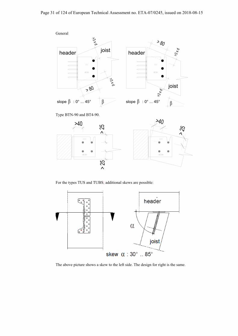
General
>3 x
d
>3 x
d
> 80
slope : 0° ... 45°
header
joist
slope : 0° ... 45°
header joist
>3 x d
> 80
>3 x d
Type BTN-90 and BT4-90.
>40
> 25
> 25
>40
> 25
For the types TUS and TUBS; additional skews are possible:
The above picture shows a skew to the left side. The design for right is the same.

Page 32 of 124 of European Technical Assessment no. ETA-07/0245, issued on 2018-08-15
b > 160
>40 >80 >40
N
Nn 4 Nb 4Nb 2
>10 >20 >10
Nh Hh
header
joist
steel dowel Ø x L
LL
The dowels should be inserted from both sides meeting in the middle of the joist. Connection to concrete / steel
>80
dowel The connection for force direction F1 is with min. 2 anchor bolts, used in the upper holes. For an uplift force, F2 and F3 a minimum of 4 anchor bolts, must be used in the upper and lower holes.
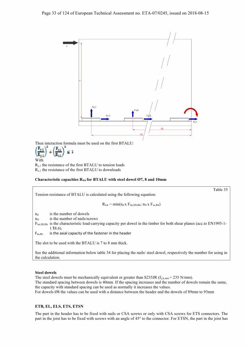
Racking check Due to the high rigidity of CLT wall, the racking load can be transferred to the BTALU at the bottom and decomposed as an axial load and a lateral load.
F=Fx,1+Fx,2+…+Fx,i and Fx,1=Fx,2=…=Fx,i Fy,1 = F x1 y/ (∑(xi2))
Optional : For the other BTALU : Fy,i = xi/x1 Fy,1
The use of formulas provides no gap between wall and floor members. With F the racking load, Y the height of the wall and Xi the distance between the BTALU and the rotation point. It is assume, that the “pressure” area is close to the end of the CLT wall, and the last Connector (it´s the right one in the picture below) doesn´t absorb any axial load.
For installations where the BT connectors are next to each
Page 33 of 124 of European Technical Assessment no. ETA-07/0245, issued on 2018-08-15
Then interaction formula must be used on the first BTALU:
With Ry,1 the resistance of the first BTALU to tension loads Rx,1 the resistance of the first BTALU to downloads Characteristic capacities R4,k for BTALU with steel dowel Ø7, 8 and 10mm
Table 35 Tension resistance of BTALU is calculated using the following equation:
R4,k = min(nd x Flat,SD,Rk; nN x Fax,Rk) nd is the number of dowels nN is the number of nails/screws Flat,SD,Rk is the characteristic load-carrying capacity per dowel in the timber for both shear planes (acc.to EN1995-1-
1 §8.6). Fax,Rk is the axial capacity of the fastener in the header The slot to be used with the BTALU is 7 to 8 mm thick. See the additional information below table 34 for placing the nails/ steel dowel, respectively the number for using in the calculation. Steel dowels The steel dowels must be mechanically equivalent or greater than S235JR (fy,k,min = 235 N/mm). The standard spacing between dowels is 40mm. If the spacing increases and the number of dowels remain the same, the capacity with standard spacing can be used as normally it increases the values. For dowels Ø8 the values can be used with a distance between the header and the dowels of 89mm to 93mm ETB, EL, ELS, ETS, ETSN
The part in the header has to be fixed with nails or CSA screws or only with CSA screws for ETS connectors. The part in the joist has to be fixed with screws with an angle of 45° to the connector. For ETSN, the part in the joist has

Page 34 of 124 of European Technical Assessment no. ETA-07/0245, issued on 2018-08-15
to be fixed with screws with an angle of 35° to the connector. The screws have to have a angle between grain of timber and the screw according the approval of the screws. For the ETB, ETS & ETSN both parts of the connector are to be fixed separately on the header and the joist before assembly of the connection
For the types EL and EL-S the connector has to be fixed to the joist and then connected to the header or the column.
C.3 Fastener specification and capacities
Nail and screw type
Nail and screw size (mm)
Finish According to ETA 04/0013 Annex A drawing 1 and 2
Diameter Length
Connector nail 4 35, 40, 50, 60, 75, 100
Electroplated zinc Connector screw 5 35, 40, 50
Connector nail 4,2 35, 50, 60
Connector nail 4 35, 40, 50, 60, 75, 100 stainless steel as described
Connector screw 5 35, 40, 50
F1 Screws in joist
BH
F1
F4
Joist Screws in joist
Header
BH
Page 35 of 124 of European Technical Assessment no. ETA-07/0245, issued on 2018-08-15
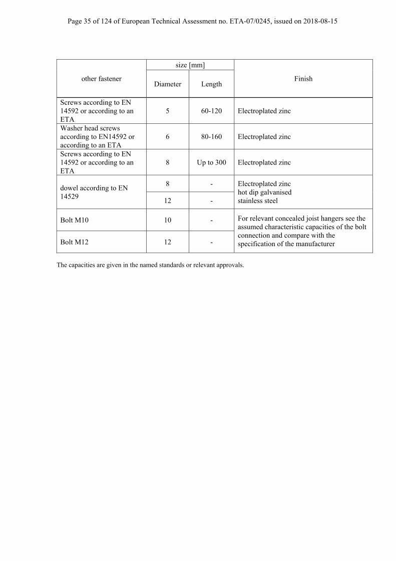
other fastener
size [mm]
Finish Diameter Length
Screws according to EN 14592 or according to an ETA
5 60-120 Electroplated zinc
Washer head screws according to EN14592 or according to an ETA
6 80-160 Electroplated zinc
Screws according to EN 14592 or according to an ETA
8 Up to 300 Electroplated zinc
dowel according to EN 14529
8 - Electroplated zinc hot dip galvanised stainless steel 12 -
Bolt M10 10 - For relevant concealed joist hangers see the assumed characteristic capacities of the bolt connection and compare with the specification of the manufacturer Bolt M12 12 -
The capacities are given in the named standards or relevant approvals.
Page 36 of 124 of European Technical Assessment no. ETA-07/0245, issued on 2018-08-15
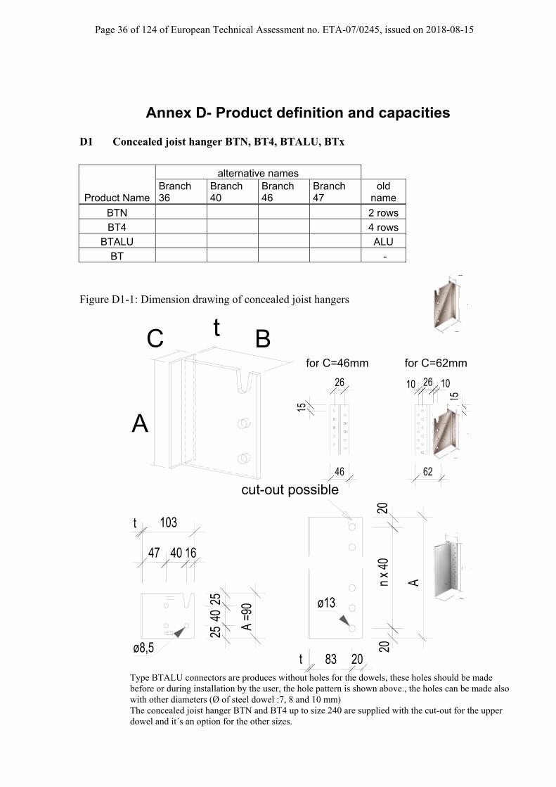
Annex D- Product definition and capacities D1 Concealed joist hanger BTN, BT4, BTALU, BTx
Product Name
alternative names Branch 36
Branch 40
Branch 46
Branch 47
old name
BTN 2 rows
BT4 4 rows
BTALU ALU
BT -
Figure D1-1: Dimension drawing of concealed joist hangers
A
BC t 15
26
15
10 26 10
46 62
for C=46mm for C=62mm
t 83 20
20n
x 40
20
A
t 103
47 40 16
2540
25
A =9
0
ø8,5
ø13
cut-out possible
Type BTALU connectors are produces without holes for the dowels, these holes should be made before or during installation by the user, the hole pattern is shown above., the holes can be made also with other diameters (Ø of steel dowel :7, 8 and 10 mm) The concealed joist hanger BTN and BT4 up to size 240 are supplied with the cut-out for the upper dowel and it´s an option for the other sizes.
C
A
B
B
A
C
A
C
B

Page 37 of 124 of European Technical Assessment no. ETA-07/0245, issued on 2018-08-15
Additional Option for outside using For the types BTALU, up to size 240, and the BT made from stainless steel also up to size 240, it´s allowed to reduce the distance of the steel dowel to the end grain of the joist like the following. In this case, full threaded screws have to be placed as given in the picture. An approval/assessment for the screw and the given distances is necessary. The minimum edge and end distances for the full threaded screws have to be observe according to the approval/ assessment of the used screws. For a construction in this way the load directions F1, F2 and F4 are possible. This application is an option for service class 3, e.g. balcony, where a distance is meaningful for a good aeration. A professional construction for a wood preservation is required.
Page 38 of 124 of European Technical Assessment no. ETA-07/0245, issued on 2018-08-15
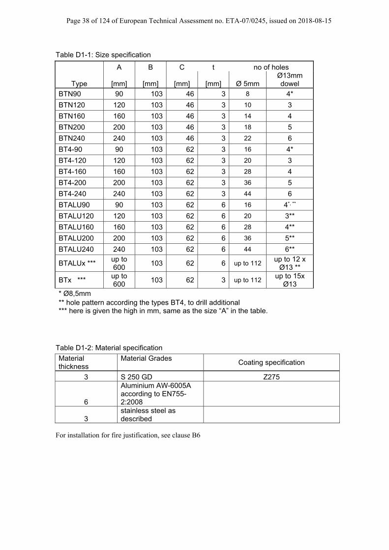
Table D1-1: Size specification
A B C t no of holes
Type [mm] [mm] [mm] [mm] Ø 5mm Ø13mm dowel
BTN90 90 103 46 3 8 4*
BTN120 120 103 46 3 10 3
BTN160 160 103 46 3 14 4
BTN200 200 103 46 3 18 5
BTN240 240 103 46 3 22 6
BT4-90 90 103 62 3 16 4*
BT4-120 120 103 62 3 20 3
BT4-160 160 103 62 3 28 4
BT4-200 200 103 62 3 36 5
BT4-240 240 103 62 3 44 6
BTALU90 90 103 62 6 16 4*, **
BTALU120 120 103 62 6 20 3**
BTALU160 160 103 62 6 28 4**
BTALU200 200 103 62 6 36 5**
BTALU240 240 103 62 6 44 6**
BTALUx *** up to 600
103 62 6 up to 112 up to 12 x
Ø13 **
BTx *** up to 600
103 62 3 up to 112 up to 15x
Ø13 * Ø8,5mm ** hole pattern according the types BT4, to drill additional *** here is given the high in mm, same as the size “A” in the table.
Table D1-2: Material specification
Material thickness
Material Grades
Coating specification
3 S 250 GD Z275
6
Aluminium AW-6005A according to EN755-2:2008
3 stainless steel as described
For installation for fire justification, see clause B6

Page 39 of 124 of European Technical Assessment no. ETA-07/0245, issued on 2018-08-15
Characteristic capacities The tables are based on a timber having a density of 350 kg/m³ and a slope of 0° For other configurations the following modification are necessary:
for different density the values shall be multiplied by: for different slope β
ρk = 380 410 430,0 β 0° 15° 30° 45° factor 1,05 1,10 1,13 factor 1 0,95 0,9 0,85
only for less as 7 SD, for 7 or more SD no reducing is necessary
SD = Steel dowel For using steel dowels with a length of 60mm the values for steel dowel with 80mm may be multiplied by 0,95; only for the types BTN90 and BT4-90 the values for a dowel with l=60mm are given directly.
Characteristic capacity R1,k [kN] for BTN90/ BT4-90 and steel dowel Ø8mm
BTN90 / BT4-90 R1,k [kN] to beam CNA 4,0x50 kg/m³ Timber width = length of steel dowel [mm] nN 60 80 100 ≥ 120 8 8,3 9,2 10,3 11,02 16 10,8 11,8 12,9 13,72
BTN90 / BT4-90 R1,k [kN] to column
CNA 4,0x50 Timber width = length of steel dowel [mm]
nN 60 80 100 ≥ 120
4 7,1 7,9 8,6 8,9 8 9,0 9,9 10,9 11,6
BTN90 / BT4-90 R3,k [kN] to column
CNA 4,0x50
Timber width = length of steel dowel [mm]
nN 60 80 100 ≥ 120
without screws
4 1,2 1,6 2,0 2,4 8 1,5 1,9 2,3 2,7
with screws
4 1,7 3,4 4,7 5,0 8 1,9 3,7 4,7 5,8
BTN90 / BT4-90column nailing
Page 40 of 124 of European Technical Assessment no. ETA-07/0245, issued on 2018-08-15
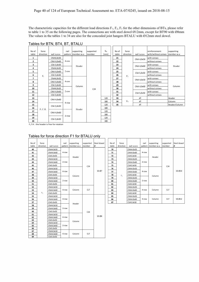
The characteristic capacities for the different load directions F1, F2, F3 for the other dimensions of BTs, please refer to table 1 to 35 on the following pages. The connections are with steel dowel Ø12mm, except for BT90 with Ø8mm The values in the tables 1 to 34 are also for the concealed joist hangers BTALU with Ø12mm steel dowel. Tables for BTN, BT4, BT, BTALU
No of
table
force
direction nail /screwnail
pattern
supporting
member as a
supported
member
bH
[mm]
No of
table
force
direction nail /screwreinforcement:
with/without screws
supporting
member as a
1 CNA4,0x50 21 with screws
2 CNA 4,0x60 22 without screws
3 CSA 5,0x50 23 with screws
4 CNA4,0x50 24 without screws
5 CNA 4,0x60 25 with screws
6 CSA 5,0x50 26 without screws
7 CNA4,0x50 27 with screws
8 CNA 4,0x60 28 without screws
9 CSA 5,0x50 29 with screws
10 CNA4,0x50 30 without screws
11 CNA 4,0x60 31 with screws
12 CSA 5,0x50 32 without screws
13 120 33 all Header
14 180 34 all Column
15 120 35 all Header/Column
16 180
17 120
18 180
19 120
20 180
F1 f.H. : the header is free for rotation
Header
Column
Header
C24
Header
Column
F1
F1 f. H.
4-row
2-row
4-row
2-row
4‐row
2‐row
CNA 4,0x60
CSA 5,0x50
CNA 4,0x60
CSA 5,0x50
CNA 4,0x50
CNA 4,0x60
CSA 5,0x50
CNA 4,0x50
CNA 4,0x60
CSA 5,0x50
F3
F4
Tables for force direction F1 for BTALU only
No of
table
force
direction nail /screwnail
pattern
supporting
member as a
supported
member
Steel dowel
Ø
No of
table
force
direction nail /screwnail
pattern
supporting
member as a
supported
member
Steel dowel
Ø
40 CNA4.0x50 70 CNA4.0x50
41 CNA4.0x60 71 CNA4.0x60
42 CSA5.0x50 72 CSA5.0x50
43 CNA4.0x50 73 CNA4.0x50
44 CNA4.0x60 74 CNA4.0x60
45 CSA5.0x50 75 CSA5.0x50
46 CNA4.0x50 76 CNA4.0x50
47 CNA4.0x60 77 CNA4.0x60
48 CSA5.0x50 78 CSA5.0x50
49 CNA4.0x50 79 CNA4.0x50
50 CNA4.0x60 80 CNA4.0x60
51 CSA5.0x50 81 CSA5.0x50
52 CNA4.0x50 82 CNA4.0x50
53 CNA4.0x60 83 CNA4.0x60
54 CSA5.0x50 84 CSA5.0x50
55 CNA4.0x50 85 CNA4.0x50
56 CNA4.0x60 86 CNA4.0x60
57 CSA5.0x50 87 CSA5.0x50
58 CNA4.0x50
59 CNA4.0x60
60 CSA5.0x50
61 CNA4.0x50
62 CNA4.0x60
63 CSA5.0x50
64 CNA4.0x50
65 CNA4.0x60
66 CSA5.0x50
67 CNA4.0x50
68 CNA4.0x60
69 CSA5.0x50
F1
F1
Column CLT
SD Ø7 SD Ø10
SD Ø12
Column CLT
Column CLT
CLT Column
2‐row
SD Ø8
C24
Header
Column
4‐row
2‐row
4‐row
2‐row
4‐row
4‐row
Header
Column
4‐row
4‐row
Header
C24
C24
2‐row
4‐row
2‐row
4‐row
Column
2‐row
4‐row
4‐row
Page 41 of 124 of European Technical Assessment no. ETA-07/0245, issued on 2018-08-15
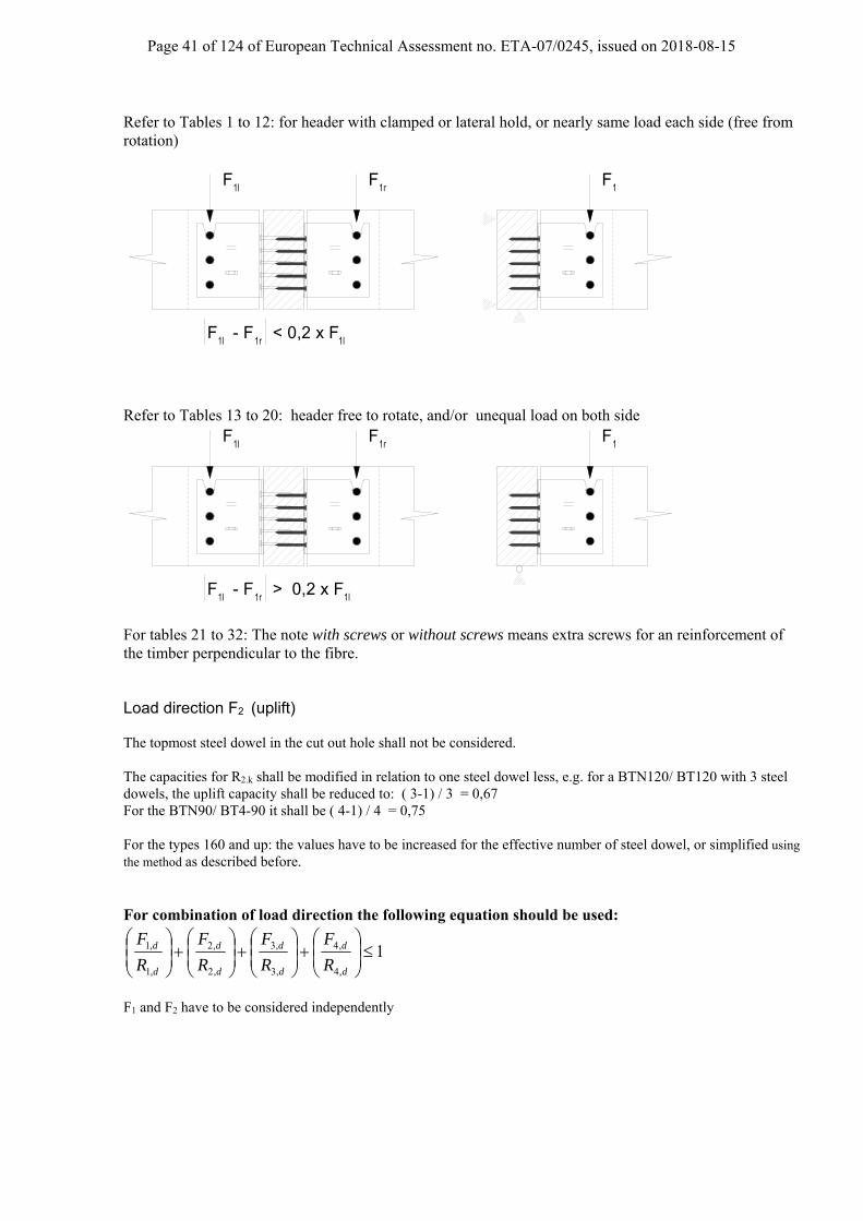
Refer to Tables 1 to 12: for header with clamped or lateral hold, or nearly same load each side (free from rotation)
F 1l 1r
F
- F < 0,2 x F 1r
F 1l 1l
1F
Refer to Tables 13 to 20: header free to rotate, and/or unequal load on both side
F 1l 1r
F
- F > 0,2 x F 1r
F 1l 1l
1F
For tables 21 to 32: The note with screws or without screws means extra screws for an reinforcement of the timber perpendicular to the fibre. Load direction F2 (uplift) The topmost steel dowel in the cut out hole shall not be considered. The capacities for R2.k shall be modified in relation to one steel dowel less, e.g. for a BTN120/ BT120 with 3 steel dowels, the uplift capacity shall be reduced to: ( 3-1) / 3 = 0,67 For the BTN90/ BT4-90 it shall be ( 4-1) / 4 = 0,75 For the types 160 and up: the values have to be increased for the effective number of steel dowel, or simplified using the method as described before. For combination of load direction the following equation should be used:
1,4
,4
,3
,3
,2
,2
,1
,1
d
d
d
d
d
d
d
d
R
F
R
F
R
F
R
F
F1 and F2 have to be considered independently

Page 42 of 124 of European Technical Assessment no. ETA-07/0245, issued on 2018-08-15
R1,k 4-row header C24 table 1
no of SD nN [kN] nN [kN] nN [kN] nN [kN] nN [kN] nN [kN]
20 18,2 20 19,4 20 20,7 20 22,3 20 23,9 20 23,944 32,2 44 34,5 48 37,6 48 41,2 52 45,0 52 49,128 29,5 28 31,2 28 33,3 28 35,7 28 38,2 28 38,548 43,0 52 46,1 56 50,1 56 55,0 60 60,1 64 65,536 41,9 36 44,3 36 47,2 36 50,4 36 53,9 36 54,956 53,9 60 57,6 60 62,7 64 68,7 68 75,1 72 81,944 54,9 44 57,9 44 61,7 44 65,9 44 70,3 44 72,364 64,6 64 69,2 68 75,3 72 82,4 76 90,1 80 98,352 68,0 56 74,4 60 82,0 64 90,3 68 99,1 72 108,368 75,4 72 80,7 76 87,8 80 96,1 84 105,2 88 114,756 78,5 60 85,5 64 93,8 68 103,0 72 112,8 80 125,772 86,2 76 92,3 80 100,5 84 109,9 88 120,2 96 131,264 91,6 68 99,0 72 108,2 76 118,4 80 129,3 88 143,080 97,0 84 103,8 88 113,0 92 123,6 96 135,3 104 147,668 102,2 72 110,3 76 120,2 80 131,4 88 145,5 92 158,084 107,8 88 115,4 92 125,6 96 137,4 104 150,3 108 164,072 112,9 76 121,5 80 132,3 88 146,6 92 159,6 100 175,488 118,6 92 126,9 96 138,1 104 151,2 108 165,3 116 180,476 123,6 80 132,9 88 146,5 92 159,7 100 175,8 100 188,192 129,3 96 138,4 104 150,7 108 164,9 116 180,4 116 195,8
R1,k 4-row header C24 table 2
no of SD nN [kN] nN [kN] nN [kN] nN [kN] nN [kN] nN [kN]
20 19,7 20 20,8 20 22,2 20 23,7 20 25,3 20 25,440 32,2 40 34,5 40 37,6 44 41,1 48 45,0 48 49,128 31,8 28 33,5 28 35,6 28 37,9 28 40,4 28 40,944 43,1 48 46,1 48 50,2 52 54,9 52 60,0 56 65,636 44,9 36 47,2 36 50,2 36 53,4 36 56,8 36 58,152 53,8 52 57,7 56 62,7 60 68,6 60 75,1 64 82,044 58,4 44 61,4 44 65,2 44 69,5 44 73,9 44 76,356 64,6 60 69,2 60 75,3 64 82,5 68 90,2 72 98,444 65,8 48 72,5 52 80,3 56 88,9 60 97,9 64 107,360 75,4 64 80,7 68 87,8 72 96,1 76 105,2 80 114,752 79,5 52 83,8 56 92,4 60 101,8 64 111,8 72 125,268 86,2 68 92,3 72 100,5 76 109,9 80 120,3 88 131,256 90,3 60 98,0 64 107,4 68 117,7 72 128,7 76 140,272 97,0 76 103,8 80 113,0 84 123,6 88 135,3 92 147,660 101,1 64 109,4 68 119,6 72 130,8 76 142,8 84 158,076 107,8 80 115,3 84 125,5 88 137,4 92 150,3 100 164,064 112,0 68 120,9 72 131,8 76 144,0 84 159,6 88 173,180 118,6 84 126,9 88 138,1 92 151,1 100 165,4 104 180,468 122,9 72 132,4 80 146,4 84 159,6 88 173,7 96 190,984 129,4 88 138,5 96 150,7 100 164,9 104 180,4 112 196,8
R1,k 4-row header C24 table 3
no of SD nN [kN] nN [kN] nN [kN] nN [kN] nN [kN] nN [kN]
20 28,2 20 29,2 20 30,5 20 31,9 20 33,3 20 33,824 32,3 28 34,5 28 37,6 28 41,2 32 45,0 32 49,128 42,7 28 44,6 28 46,9 28 49,2 28 51,5 28 52,832 43,0 32 46,1 32 50,2 36 54,9 36 60,1 40 65,536 53,8 36 57,6 36 62,5 36 66,4 36 69,9 36 72,636 53,8 36 57,6 40 62,7 40 68,6 44 75,1 44 81,944 64,6 44 69,2 44 75,3 44 82,3 44 87,9 44 92,440 64,6 40 69,2 44 75,3 48 82,4 48 90,1 52 98,328 60,6 28 63,2 32 71,9 36 81,1 40 90,6 40 92,844 75,4 44 80,8 48 87,8 52 96,1 56 105,2 56 114,732 71,6 32 74,5 36 83,7 40 93,4 44 103,5 48 112,848 86,2 48 92,3 52 100,4 56 109,9 60 120,2 64 131,236 82,6 36 85,7 40 95,4 44 105,6 48 116,0 56 132,852 97,0 52 103,8 56 113,0 60 123,7 64 135,3 72 147,640 93,6 44 102,8 44 106,9 52 123,9 56 135,0 60 145,556 107,8 60 115,3 60 125,5 68 137,4 72 150,3 76 164,044 104,5 48 114,0 52 124,7 56 135,9 60 147,3 68 165,460 118,5 64 126,9 68 138,1 72 151,1 76 165,3 84 180,448 115,3 52 125,2 56 136,3 60 147,7 68 166,2 72 177,764 129,3 68 138,4 72 150,7 76 164,9 84 180,4 88 196,8
10080 120
100
140 160
12
8
6
160 180140
11
80
10
3
4
9
5
120
7
3
4
6
11
5
100
12
7
8
9
9
8
12
11
3
4
5
7
6
180
10
160140120
10
80 180
CNA 4,0x50 SD: Ø 12mm
width of timber = length of the dowels [mm]CSA 5,0x50 SD: Ø 12mm
width of timber = length of the dowels [mm]CNA 4,0x60 SD: Ø 12mm
width of timber = length of the dowels [mm]

Page 43 of 124 of European Technical Assessment no. ETA-07/0245, issued on 2018-08-15
R1,k 2-row header C24 table 4
no of SD nN [kN] nN [kN] nN [kN] nN [kN] nN [kN] nN [kN]
10 14,5 10 15,6 10 16,9 10 18,3 10 19,5 10 19,532 32,2 32 34,6 34 37,6 36 41,1 38 45,0 40 49,114 23,2 14 24,7 14 26,6 14 28,5 14 30,1 14 30,136 43,0 38 46,2 40 50,2 42 55,0 44 60,0 48 65,518 32,7 18 34,7 18 37,0 18 39,1 18 39,9 18 39,942 53,9 44 57,6 46 62,8 48 68,6 52 75,1 54 82,022 42,6 22 45,0 22 47,5 22 48,8 22 48,8 22 48,846 64,6 50 69,2 52 75,3 54 82,4 58 90,2 58 97,044 70,9 46 76,0 48 82,2 50 88,9 50 93,7 50 97,052 75,4 54 80,8 56 87,8 58 95,5 58 101,8 58 107,448 81,4 50 87,0 50 91,9 50 97,0 50 101,9 50 104,456 86,2 58 92,2 58 98,8 58 105,1 58 111,1 58 115,550 90,1 50 94,3 50 99,4 50 104,4 50 108,6 50 110,058 96,2 58 101,3 58 107,4 58 113,6 58 119,3 58 122,750 96,9 50 101,2 50 106,1 50 110,0 50 110,8 50 110,858 104,2 58 109,2 58 115,2 58 121,1 58 126,0 58 127,850 103,2 50 107,3 50 110,6 50 110,8 50 110,8 50 110,858 111,3 58 116,4 58 122,2 58 127,1 58 128,5 58 128,550 108,6 50 110,8 50 110,8 50 110,8 50 110,8 50 110,858 118,0 58 122,8 58 127,5 58 128,5 58 128,5 58 128,5
R1,k 2-row header C24 table 5
no of SD nN [kN] nN [kN] nN [kN] nN [kN] nN [kN] nN [kN]
10 15,2 10 16,3 10 17,6 10 18,9 10 20,1 10 20,128 32,3 30 34,5 30 37,6 32 41,2 34 45,1 36 49,114 24,3 14 25,8 14 27,6 14 29,5 14 31,3 14 31,334 43,0 34 46,1 36 50,2 38 55,0 40 60,1 42 65,518 34,2 18 36,1 18 38,4 18 40,6 18 42,3 18 42,438 53,9 40 57,6 42 62,7 44 68,7 46 75,1 50 81,922 44,5 22 46,8 22 49,4 22 51,6 22 52,0 22 52,042 64,7 44 69,2 46 75,3 50 82,4 52 90,1 56 98,438 68,7 42 76,1 44 82,4 48 91,4 50 98,6 50 102,846 75,4 50 80,7 52 87,9 56 96,1 58 105,2 58 112,444 81,6 46 87,4 48 94,3 50 101,7 50 106,8 50 110,052 86,2 54 92,3 56 100,4 58 109,1 58 116,2 58 122,148 92,4 50 98,6 50 103,9 50 109,2 50 113,8 50 115,956 97,0 58 103,8 58 111,6 58 118,6 58 124,8 58 129,250 101,2 50 105,6 50 110,8 50 115,4 50 118,1 50 118,258 107,5 58 113,4 58 120,1 58 126,5 58 132,0 58 134,850 107,6 50 111,9 50 116,3 50 118,2 50 118,2 50 118,258 115,7 58 121,1 58 127,4 58 133,0 58 136,7 58 137,150 113,3 50 116,8 50 118,2 50 118,2 50 118,2 50 118,258 122,7 58 127,9 58 133,5 58 137,0 58 137,1 58 137,1
R1,k 2-row header C24 table 6
no of SD nN [kN] nN [kN] nN [kN] nN [kN] nN [kN] nN [kN]
10 19,0 10 19,8 10 20,7 10 21,7 10 22,7 10 22,720 32,2 20 34,5 22 37,6 22 41,1 24 45,0 26 49,114 29,3 14 30,4 14 31,6 14 32,8 14 33,9 14 33,924 43,0 24 46,1 26 50,1 28 54,9 30 60,0 32 65,518 40,0 18 41,2 18 42,6 18 43,9 18 44,8 18 44,928 53,8 30 57,6 30 62,7 34 68,6 36 75,1 38 81,922 50,8 22 52,2 22 53,6 22 54,7 22 55,2 22 55,232 64,6 34 69,2 36 75,3 38 82,4 42 90,1 44 98,328 65,2 30 70,5 32 76,2 36 85,9 38 91,9 42 101,636 75,4 38 80,7 40 87,8 44 96,1 46 105,2 50 114,732 76,0 34 81,5 36 87,4 40 97,3 44 107,5 48 117,540 86,2 42 92,2 44 100,4 48 109,9 52 120,2 56 131,236 86,7 38 92,3 42 102,3 46 112,6 50 123,0 50 124,344 97,0 46 103,8 50 113,0 54 123,6 58 135,3 58 141,540 97,3 42 103,0 46 113,2 50 123,6 50 125,1 50 125,548 107,8 50 115,4 54 125,5 58 137,3 58 142,4 58 144,344 107,8 48 117,6 50 124,0 50 125,4 50 125,5 50 125,552 118,5 56 126,9 58 137,9 58 142,8 58 144,9 58 145,548 118,3 50 124,2 50 125,4 50 125,5 50 125,5 50 125,556 129,3 58 138,1 58 142,9 58 145,1 58 145,6 58 145,6
120 140
140 160
100
120
80
12
10
80
7
5
6
11
4
6
7
8
5
3
4
160 180
180
120
8
100
12
11
10
5
7
3
6
9
80
11
100
12
8
9
3
180160140
4
width of timber = length of the dowels [mm]CSA 5,0x50 SD: Ø 12mm
9
10
CNA 4,0x50 SD: Ø 12mm
width of timber = length of the dowels [mm]
width of timber = length of the dowels [mm]CNA 4,0x60 SD: Ø 12mm
2-row
Page 44 of 124 of European Technical Assessment no. ETA-07/0245, issued on 2018-08-15
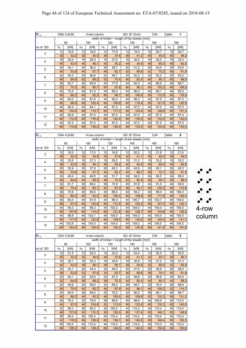
R1,k 4-row column C24 table 7
no of SD nN [kN] nN [kN] nN [kN] nN [kN] nN [kN] nN [kN]
12 15,5 12 16,6 12 17,9 12 19,4 12 20,7 12 20,732 32,2 32 34,5 36 37,6 36 41,2 40 45,0 40 49,216 24,4 16 26,0 16 27,9 16 30,0 16 32,0 16 32,040 43,0 40 46,1 40 50,2 44 54,9 48 60,0 48 65,520 34,1 20 36,2 20 38,7 20 41,2 20 43,4 20 43,544 53,8 44 57,7 48 62,7 52 68,6 52 75,2 56 81,924 44,3 24 46,8 24 49,7 24 52,3 24 53,2 24 53,248 64,6 52 69,2 52 75,4 56 82,4 60 90,1 60 98,036 62,7 40 69,9 44 77,9 44 82,3 44 86,6 44 88,752 75,5 56 80,7 60 87,8 60 96,1 60 103,2 60 109,240 73,4 44 81,0 44 85,4 44 90,0 44 94,1 44 95,556 86,2 60 92,2 60 99,7 60 106,6 60 112,9 60 118,044 84,0 44 87,9 44 92,4 44 96,3 44 97,5 44 97,560 96,9 60 102,4 60 108,9 60 115,4 60 121,5 60 125,544 90,4 44 94,1 44 97,3 44 97,5 44 97,5 44 97,560 105,4 60 110,7 60 117,0 60 123,4 60 128,8 60 131,344 95,8 44 97,5 44 97,5 44 97,5 44 97,5 44 97,560 112,9 60 118,2 60 124,4 60 130,0 60 133,0 60 133,044 97,5 44 97,5 44 97,5 44 97,5 44 97,5 44 97,560 119,8 60 125,0 60 130,5 60 133,0 60 133,0 60 133,0
R1,k 4-row column C24 table 8
no of SD nN [kN] nN [kN] nN [kN] nN [kN] nN [kN] nN [kN]
12 16,5 12 17,5 12 18,8 12 20,2 12 21,6 12 21,628 32,3 32 34,5 32 37,6 32 41,1 36 45,0 36 49,216 25,8 16 27,3 16 29,2 16 31,2 16 33,2 16 33,236 43,0 36 46,1 36 50,2 40 54,9 40 60,0 44 65,520 35,9 20 37,9 20 40,3 20 42,8 20 45,1 20 45,340 53,8 40 57,7 44 62,7 44 68,7 48 75,1 52 81,924 46,4 24 48,8 24 51,7 24 54,5 24 56,5 24 56,644 64,6 44 69,2 48 75,3 52 82,4 56 90,1 56 98,432 61,7 36 69,2 36 72,9 40 81,8 44 91,0 44 93,648 75,4 52 80,7 52 87,9 56 96,1 60 105,2 60 113,836 72,6 40 80,6 44 89,5 44 94,2 44 98,4 44 100,352 86,2 56 92,2 60 100,4 60 109,8 60 117,8 60 124,340 83,4 44 91,9 44 96,4 44 100,7 44 103,7 44 104,056 97,0 60 103,8 60 112,5 60 120,3 60 127,0 60 132,144 94,3 44 98,2 44 102,2 44 104,0 44 104,0 44 104,060 107,8 60 114,5 60 121,8 60 128,7 60 134,8 60 138,244 99,9 44 103,1 44 104,0 44 104,0 44 104,0 44 104,060 117,0 60 122,8 60 129,5 60 135,8 60 140,5 60 141,744 103,8 44 104,0 44 104,0 44 104,0 44 104,0 44 104,060 124,5 60 130,0 60 136,2 60 140,9 60 141,8 60 141,8
R1,k 4-row column C24 table 9
no of SD nN [kN] nN [kN] nN [kN] nN [kN] nN [kN] nN [kN]
12 21,4 12 22,3 12 23,3 12 24,4 12 25,4 12 25,520 32,2 20 34,6 24 37,6 24 41,1 24 45,1 28 49,116 32,1 16 33,3 16 34,6 16 35,9 16 37,2 16 37,424 43,0 28 46,1 28 50,1 28 54,9 32 60,0 32 65,520 43,1 20 44,4 20 46,0 20 47,5 20 48,8 20 49,028 53,8 32 57,6 32 62,7 36 68,6 36 75,1 40 81,924 54,1 24 55,6 24 57,3 24 58,8 24 59,8 24 60,032 64,6 36 69,2 36 75,3 40 82,4 44 90,1 44 98,320 49,9 24 59,0 24 60,0 28 69,7 32 79,4 36 88,636 75,4 40 80,7 40 87,9 44 96,1 48 105,2 52 114,724 60,0 28 69,5 32 79,2 32 80,2 36 90,1 40 99,740 86,2 44 92,2 48 100,4 48 109,9 52 120,3 56 131,228 70,2 32 79,9 36 89,8 40 99,8 44 109,9 44 110,344 97,0 48 103,8 52 113,0 56 123,6 60 135,3 60 145,032 80,3 36 90,2 40 100,2 44 110,3 44 110,4 44 110,448 107,8 52 115,3 56 125,5 60 137,4 60 146,1 60 148,836 90,4 40 100,4 44 110,4 44 110,4 44 110,4 44 110,452 118,5 56 126,9 60 138,1 60 146,5 60 149,4 60 150,340 100,4 44 110,4 44 110,4 44 110,4 44 110,4 44 110,456 129,3 60 138,4 60 146,5 60 149,5 60 150,6 60 150,6
CSA 5,0x50 SD: Ø 12mmwidth of timber = length of the dowels [mm]
CNA 4,0x60 SD: Ø 12mmwidth of timber = length of the dowels [mm]
CNA 4,0x50 SD: Ø 12mmwidth of timber = length of the dowels [mm]
180
5
18080 120100 140 160
4
3
12
10
5
6
3
80 100
4
180160120
6
7
11
12
8
10
9
11
4
3
9
6
7
8
5
7
8
9
10
12
11
140
140 16010080 120
4-rowcolumn

Page 45 of 124 of European Technical Assessment no. ETA-07/0245, issued on 2018-08-15
R1,k 2-row column C24 table 10
no of SD nN [kN] nN [kN] nN [kN] nN [kN] nN [kN] nN [kN]
6 13,0 6 13,3 6 13,3 6 13,3 6 13,3 6 13,324 32,2 26 34,5 26 37,7 28 41,1 30 45,0 30 48,78 17,7 8 17,7 8 17,7 8 17,7 8 17,7 8 17,7
28 43,0 30 46,1 30 49,4 30 51,8 30 53,9 30 55,310 22,2 10 22,2 10 22,2 10 22,2 10 22,2 10 22,230 51,5 30 53,3 30 55,5 30 57,7 30 59,7 30 60,612 26,6 12 26,6 12 26,6 12 26,6 12 26,6 12 26,630 56,6 30 58,4 30 60,6 30 62,8 30 64,6 30 65,022 48,6 22 48,8 22 48,8 22 48,8 22 48,8 22 48,830 61,1 30 62,9 30 64,9 30 66,2 30 66,5 30 66,522 48,8 22 48,8 22 48,8 22 48,8 22 48,8 22 48,830 64,9 30 66,1 30 66,5 30 66,5 30 66,5 30 66,522 48,8 22 48,8 22 48,8 22 48,8 22 48,8 22 48,830 66,5 30 66,5 30 66,5 30 66,5 30 66,5 30 66,522 48,8 22 48,8 22 48,8 22 48,8 22 48,8 22 48,830 66,5 30 66,5 30 66,5 30 66,5 30 66,5 30 66,522 48,8 22 48,8 22 48,8 22 48,8 22 48,8 22 48,830 66,5 30 66,5 30 66,5 30 66,5 30 66,5 30 66,522 48,8 22 48,8 22 48,8 22 48,8 22 48,8 22 48,830 66,5 30 66,5 30 66,5 30 66,5 30 66,5 30 66,5
R1,k 2-row column C24 table 11
no of SD nN [kN] nN [kN] nN [kN] nN [kN] nN [kN] nN [kN]
6 13,0 6 13,8 6 14,2 6 14,2 6 14,2 6 14,222 32,2 22 34,5 24 37,6 26 41,1 28 45,0 28 49,28 18,9 8 18,9 8 18,9 8 18,9 8 18,9 8 18,9
26 43,0 28 46,1 30 50,1 30 54,8 30 57,8 30 59,810 23,6 10 23,6 10 23,6 10 23,6 10 23,6 10 23,630 53,9 30 56,7 30 59,2 30 61,5 30 63,6 30 64,712 28,4 12 28,4 12 28,4 12 28,4 12 28,4 12 28,430 60,2 30 62,1 30 64,3 30 66,4 30 68,3 30 68,822 51,2 22 52,0 22 52,0 22 52,0 22 52,0 22 52,030 64,7 30 66,5 30 68,5 30 70,1 30 70,9 30 70,922 52,0 22 52,0 22 52,0 22 52,0 22 52,0 22 52,030 68,4 30 69,9 30 70,8 30 70,9 30 70,9 30 70,922 52,0 22 52,0 22 52,0 22 52,0 22 52,0 22 52,030 70,7 30 70,9 30 70,9 30 70,9 30 70,9 30 70,922 52,0 22 52,0 22 52,0 22 52,0 22 52,0 22 52,030 70,9 30 70,9 30 70,9 30 70,9 30 70,9 30 70,922 52,0 22 52,0 22 52,0 22 52,0 22 52,0 22 52,030 70,9 30 70,9 30 70,9 30 70,9 30 70,9 30 70,922 52,0 22 52,0 22 52,0 22 52,0 22 52,0 22 52,030 70,9 30 70,9 30 70,9 30 70,9 30 70,9 30 70,9
R1,k 2-row column C24 table 12
no of SD nN [kN] nN [kN] nN [kN] nN [kN] nN [kN] nN [kN]
6 14,2 6 14,7 6 15,0 6 15,1 6 15,1 6 15,116 32,2 18 34,5 18 37,6 20 41,1 22 45,0 22 49,18 20,0 8 20,1 8 20,1 8 20,1 8 20,1 8 20,1
20 43,0 22 46,1 24 50,1 24 55,0 26 60,1 28 65,610 25,1 10 25,1 10 25,1 10 25,1 10 25,1 10 25,124 53,8 26 57,6 28 62,7 30 68,6 30 72,3 30 73,212 30,1 12 30,1 12 30,1 12 30,1 12 30,1 12 30,128 64,6 30 69,2 30 72,4 30 73,5 30 74,3 30 74,522 54,8 22 55,1 22 55,2 22 55,2 22 55,2 22 55,230 72,5 30 73,5 30 74,3 30 74,9 30 75,2 30 75,322 55,2 22 55,2 22 55,2 22 55,2 22 55,2 22 55,230 74,2 30 74,8 30 75,2 30 75,3 30 75,3 30 75,322 55,2 22 55,2 22 55,2 22 55,2 22 55,2 22 55,230 75,1 30 75,3 30 75,3 30 75,3 30 75,3 30 75,322 55,2 22 55,2 22 55,2 22 55,2 22 55,2 22 55,230 75,3 30 75,3 30 75,3 30 75,3 30 75,3 30 75,322 55,2 22 55,2 22 55,2 22 55,2 22 55,2 22 55,230 75,3 30 75,3 30 75,3 30 75,3 30 75,3 30 75,322 55,2 22 55,2 22 55,2 22 55,2 22 55,2 22 55,230 75,3 30 75,3 30 75,3 30 75,3 30 75,3 30 75,3
CSA 5,0x50 SD: Ø 12mmwidth of timber = length of the dowels [mm]
CNA 4,0x60 SD: Ø 12mmwidth of timber = length of the dowels [mm]
CNA 4,0x50 SD: Ø 12mmwidth of timber = length of the dowels [mm]
10080
9
4
5
6
140 160
80
6
5
4
80
10
9
12
9
11
12
3
11
7
8
12
8
10
5
6
3
4
10
11
120
7
3
7
160120 140
100 140 160
180120
180
180100
8
2-rowcolumn
Page 46 of 124 of European Technical Assessment no. ETA-07/0245, issued on 2018-08-15
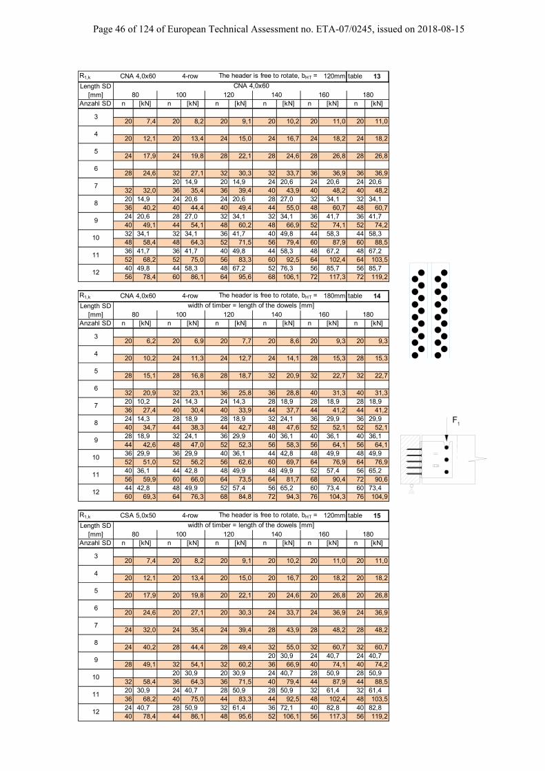
R1,k CNA 4,0x60 4-row The header is free to rotate, bHT = 120mm table 13
Anzahl SD n [kN] n [kN] n [kN] n [kN] n [kN] n [kN]
20 7,4 20 8,2 20 9,1 20 10,2 20 11,0 20 11,0
20 12,1 20 13,4 24 15,0 24 16,7 24 18,2 24 18,2
24 17,9 24 19,8 28 22,1 28 24,6 28 26,8 28 26,8
28 24,6 32 27,1 32 30,3 32 33,7 36 36,9 36 36,920 14,9 20 14,9 24 20,6 24 20,6 24 20,6
32 32,0 36 35,4 36 39,4 40 43,9 40 48,2 40 48,220 14,9 24 20,6 24 20,6 28 27,0 32 34,1 32 34,136 40,2 40 44,4 40 49,4 44 55,0 48 60,7 48 60,724 20,6 28 27,0 32 34,1 32 34,1 36 41,7 36 41,740 49,1 44 54,1 48 60,2 48 66,9 52 74,1 52 74,232 34,1 32 34,1 36 41,7 40 49,8 44 58,3 44 58,348 58,4 48 64,3 52 71,5 56 79,4 60 87,9 60 88,536 41,7 36 41,7 40 49,8 44 58,3 48 67,2 48 67,252 68,2 52 75,0 56 83,3 60 92,5 64 102,4 64 103,540 49,8 44 58,3 48 67,2 52 76,3 56 85,7 56 85,756 78,4 60 86,1 64 95,6 68 106,1 72 117,3 72 119,2
R1,k CNA 4,0x60 4-row The header is free to rotate, bHT = 180mm table 14
Anzahl SD n [kN] n [kN] n [kN] n [kN] n [kN] n [kN]
20 6,2 20 6,9 20 7,7 20 8,6 20 9,3 20 9,3
20 10,2 24 11,3 24 12,7 24 14,1 28 15,3 28 15,3
28 15,1 28 16,8 28 18,7 32 20,9 32 22,7 32 22,7
32 20,9 32 23,1 36 25,8 36 28,8 40 31,3 40 31,320 10,2 24 14,3 24 14,3 28 18,9 28 18,9 28 18,936 27,4 40 30,4 40 33,9 44 37,7 44 41,2 44 41,224 14,3 28 18,9 28 18,9 32 24,1 36 29,9 36 29,940 34,7 44 38,3 44 42,7 48 47,6 52 52,1 52 52,128 18,9 32 24,1 36 29,9 40 36,1 40 36,1 40 36,144 42,6 48 47,0 52 52,3 56 58,3 56 64,1 56 64,136 29,9 36 29,9 40 36,1 44 42,8 48 49,9 48 49,952 51,0 52 56,2 56 62,6 60 69,7 64 76,9 64 76,940 36,1 44 42,8 48 49,9 48 49,9 52 57,4 56 65,256 59,9 60 66,0 64 73,5 64 81,7 68 90,4 72 90,644 42,8 48 49,9 52 57,4 56 65,2 60 73,4 60 73,460 69,3 64 76,3 68 84,8 72 94,3 76 104,3 76 104,9
R1,k CSA 5,0x50 4-row The header is free to rotate, bHT = 120mm table 15
Anzahl SD n [kN] n [kN] n [kN] n [kN] n [kN] n [kN]
20 7,4 20 8,2 20 9,1 20 10,2 20 11,0 20 11,0
20 12,1 20 13,4 20 15,0 20 16,7 20 18,2 20 18,2
20 17,9 20 19,8 20 22,1 20 24,6 20 26,8 20 26,8
20 24,6 20 27,1 20 30,3 24 33,7 24 36,9 24 36,9
24 32,0 24 35,4 24 39,4 28 43,9 28 48,2 28 48,2
24 40,2 28 44,4 28 49,4 32 55,0 32 60,7 32 60,720 30,9 24 40,7 24 40,7
28 49,1 32 54,1 32 60,2 36 66,9 40 74,1 40 74,220 30,9 20 30,9 24 40,7 28 50,9 28 50,9
32 58,4 36 64,3 36 71,5 40 79,4 44 87,9 44 88,520 30,9 24 40,7 28 50,9 28 50,9 32 61,4 32 61,436 68,2 40 75,0 44 83,3 44 92,5 48 102,4 48 103,524 40,7 28 50,9 32 61,4 36 72,1 40 82,8 40 82,840 78,4 44 86,1 48 95,6 52 106,1 56 117,3 56 119,2
160 180
width of timber = length of the dowels [mm]80 100 120 140 160 180
width of timber = length of the dowels [mm]80 100 120 140 160 180
CNA 4,0x60
3
4
5
6
7
80 100 120 140
8
9
10
11
12
3
4
5
6
7
8
9
10
11
12
3
4
5
6
7
8
9
10
11
12
Length SD [mm]
Length SD [mm]
Length SD [mm]
1F

Page 47 of 124 of European Technical Assessment no. ETA-07/0245, issued on 2018-08-15
R1,k CSA 5,0x50 4-row The header is free to rotate, bHT = 180mm table 16
Anzahl SD n [kN] n [kN] n [kN] n [kN] n [kN] n [kN]
20 6,2 20 6,9 20 7,7 20 8,6 20 9,3 20 9,3
20 10,2 20 11,3 20 12,7 20 14,1 20 15,3 20 15,3
20 15,1 20 16,8 20 18,7 20 20,9 20 22,7 20 22,7
20 20,9 20 23,1 24 25,8 24 28,8 24 31,3 24 31,3
24 27,4 24 30,4 28 33,9 28 37,7 32 41,2 32 41,2
28 34,7 28 38,3 32 42,7 32 47,6 36 52,1 36 52,120 23,2 20 23,2 24 31,4 24 31,4
32 42,6 32 47,0 36 52,3 36 58,3 40 64,1 40 64,120 23,2 20 23,2 24 31,4 24 31,4 28 40,4 28 40,436 51,0 36 56,2 40 62,6 40 69,7 44 76,9 44 76,924 31,4 24 31,4 28 40,4 32 49,9 32 49,9 32 49,940 59,9 40 66,0 44 73,5 48 81,7 48 90,4 48 90,624 31,4 28 40,4 32 49,9 36 59,8 40 70,0 40 70,040 69,3 44 76,3 48 84,8 52 94,3 56 104,3 56 104,9
R1,k CNA 4,0x60 2-row The header is free to rotate, bHT = 120mm table 17
Anzahl SD n [kN] n [kN] n [kN] n [kN] n [kN] n [kN]10 7,5 10 7,5 10 7,5 10 7,5 10 7,5
10 7,4 12 8,2 12 9,1 12 10,2 14 11,0 14 11,014 13,5 14 13,5 14 13,5 14 13,5
14 12,1 14 13,4 16 15,0 16 16,7 18 18,2 18 18,218 20,9 18 20,9 18 20,9 18 20,9
18 17,9 18 19,8 20 22,1 20 24,6 22 26,8 22 26,822 29,2 22 29,2 22 29,2 22 29,2
20 24,6 22 27,1 24 30,3 26 33,7 26 36,9 26 36,916 17,0 18 20,9 20 24,9 22 29,2 24 33,6 24 33,624 32,0 26 35,4 28 39,4 30 43,9 32 48,2 32 48,220 24,9 22 29,2 24 33,6 26 38,2 28 42,9 28 42,928 40,2 30 44,4 32 49,4 34 55,0 36 60,7 36 60,724 33,6 26 38,2 28 42,9 30 47,6 34 57,4 34 57,432 49,1 34 54,1 36 60,2 38 66,9 42 74,1 42 74,228 42,9 30 47,6 32 52,5 36 62,4 40 72,5 40 72,536 58,4 38 64,3 40 71,5 44 79,4 48 87,9 48 88,532 52,5 34 57,4 38 67,5 40 72,5 44 82,7 46 87,840 68,2 42 75,0 46 83,3 48 92,5 52 102,4 54 103,536 62,4 38 67,5 42 77,6 46 87,8 50 98,0 50 98,044 78,4 46 86,1 50 95,6 54 106,1 58 117,3 58 118,4
R1,k CNA 4,0x60 2-row The header is free to rotate, bHT = 180mm table 18
Anzahl SD n [kN] n [kN] n [kN] n [kN] n [kN] n [kN]10 5,1 10 5,1 10 5,1 10 5,1 10 5,1 10 5,112 6,2 12 6,9 14 7,7 14 8,6 14 9,3 14 9,314 9,5 14 9,5 14 9,5 14 9,5 14 9,5 14 9,516 10,2 16 11,3 18 12,7 18 14,1 20 15,3 20 15,318 14,9 18 14,9 18 14,9 18 14,9 18 14,9 18 14,920 15,1 20 16,8 22 18,7 22 20,9 24 22,7 24 22,7
22 21,4 22 21,4 22 21,4 22 21,4 22 21,422 20,9 24 23,1 26 25,8 28 28,8 28 31,3 28 31,318 14,9 20 18,1 22 21,4 24 25,0 26 28,7 26 28,726 27,4 28 30,4 30 33,9 32 37,7 34 41,2 34 41,222 21,4 24 25,0 26 28,7 28 32,6 30 36,7 30 36,730 34,7 32 38,3 34 42,7 36 47,6 38 52,1 38 52,126 28,7 28 32,6 30 36,7 32 40,9 36 49,7 36 49,734 42,6 36 47,0 38 52,3 40 58,3 44 64,1 44 64,130 36,7 32 40,9 34 45,3 38 54,3 40 58,9 40 58,938 51,0 40 56,2 42 62,6 46 69,7 48 76,9 48 76,934 45,3 36 49,7 40 58,9 42 63,6 46 73,3 46 73,342 59,9 44 66,0 48 73,5 50 81,7 54 90,4 54 90,638 54,3 40 58,9 44 68,4 48 78,1 50 83,1 50 83,146 69,3 48 76,3 52 84,8 56 94,3 58 103,1 58 103,1
width of timber = length of the dowels [mm]80 100 120 140 160 180
width of timber = length of the dowels [mm]80 100 120 140 160 180
width of timber = length of the dowels [mm]80 100 120 140 160 180
3
4
5
6
7
8
9
10
11
12
3
4
5
6
7
8
9
10
11
12
3
4
5
6
7
8
9
10
11
12
Length SD [mm]
Length SD [mm]
Length SD [mm]
1F
2-row

Page 48 of 124 of European Technical Assessment no. ETA-07/0245, issued on 2018-08-15
R1,k CSA 5,0x50 2-row The header is free to rotate, bHT = 120mm table 19
Anzahl SD n [kN] n [kN] n [kN] n [kN] n [kN] n [kN]
10 7,4 10 8,2 10 9,1 10 10,2 10 11,0 10 11,0
10 12,1 10 13,4 10 15,0 12 16,7 12 18,2 12 18,2
12 17,9 12 19,8 14 22,1 14 24,6 16 26,8 16 26,8
14 24,6 16 27,1 16 30,3 18 33,7 20 36,9 20 36,910 15,5 10 15,5 12 20,4 14 25,5 16 30,7 16 30,718 32,0 18 35,4 20 39,4 22 43,9 24 48,2 24 48,212 20,4 14 25,5 16 30,7 18 36,0 20 41,4 20 41,420 40,2 22 44,4 24 49,4 26 55,0 28 60,7 28 60,716 30,7 18 36,0 20 41,4 22 46,8 26 57,5 26 57,524 49,1 26 54,1 28 60,2 30 66,9 34 74,1 34 74,220 41,4 22 46,8 24 52,1 28 62,9 30 68,2 30 68,228 58,4 30 64,3 32 71,5 36 79,4 38 87,9 38 88,522 46,8 26 57,5 28 62,9 32 73,5 36 84,1 36 84,130 68,2 34 75,0 36 83,3 40 92,5 44 102,4 44 103,526 57,5 30 68,2 34 78,8 38 89,3 42 99,8 42 99,834 78,4 38 86,1 42 95,6 46 106,1 50 117,3 50 119,2
R1,k CSA 5,0x50 2-row The header is free to rotate, bHT = 180mm table 20
Anzahl SD n [kN] n [kN] n [kN] n [kN] n [kN] n [kN]
10 6,2 10 6,9 10 7,7 10 8,6 10 9,3 10 9,3
10 10,2 10 11,3 12 12,7 12 14,1 12 15,3 12 15,3
12 15,1 14 16,8 14 18,7 16 20,9 16 22,7 16 22,7
16 20,9 16 23,1 18 25,8 18 28,8 20 31,3 20 31,310 11,6 12 15,7 12 15,7 14 20,2 16 24,9 16 24,918 27,4 20 30,4 20 33,9 22 37,7 24 41,2 24 41,212 15,7 14 20,2 16 24,9 18 29,9 20 35,0 20 35,020 34,7 22 38,3 24 42,7 26 47,6 28 52,1 28 52,116 24,9 18 29,9 20 35,0 22 40,2 24 45,5 24 45,524 42,6 26 47,0 28 52,3 30 58,3 32 64,1 32 64,120 35,0 20 35,0 24 45,5 26 50,8 28 56,2 28 56,228 51,0 28 56,2 32 62,6 34 69,7 36 76,9 36 76,922 40,2 24 45,5 28 56,2 30 61,6 34 72,4 34 72,430 59,9 32 66,0 36 73,5 38 81,7 42 90,4 42 90,626 50,8 28 56,2 32 67,0 36 77,8 38 83,2 40 88,634 69,3 36 76,3 40 84,8 44 94,3 46 104,3 48 104,9
10
11
12
Length SD [mm]
4
5
6
7
8
9
8
9
10
11
12
3
Length SD [mm]
3
4
5
6
7
width of timber = length of the dowels [mm]80 100 120 140 160 180
width of timber = length of the dowels [mm]80 100 120 140 160 180
1F
2-row

Page 49 of 124 of European Technical Assessment no. ETA-07/0245, issued on 2018-08-15
R3.k beam to beam R3,k CNA 4,0x50 with screws * table 21
number of joist min. Type SD nails b / h [mm] 60 80 100 120 140 160 180
90-2 4 8 ... / 100 1,9 3,7 4,7 5,7 5,7 5,7 5,7120-2 3 10 ... / 160 2,0 3,1 4,8 4,8 4,8 4,8 4,8160-2 4 14 ... / 200 2,7 4,2 6,5 6,5 6,5 6,5 6,5200-2 5 18 ... / 240 3,3 4,7 7,3 8,3 8,3 8,3 8,3240-2 6 22 ... / 280 4,0 5,0 7,7 10,0 10,0 10,0 10,0280-2 7 26 ... / 320 4,6 5,8 8,1 11,7 11,8 11,8 11,8320-2 8 30 ... / 360 5,2 6,5 8,6 12,4 13,6 13,6 13,6360-2 9 34 ... / 400 5,8 7,2 9,1 13,0 15,4 15,4 15,4400-2 10 38 ... / 440 6,5 7,9 9,7 13,7 17,2 17,2 17,2440-2 11 42 ... / 480 7,2 8,7 10,6 14,4 18,8 19,1 19,1480-2 12 46 ... / 520 7,8 9,6 11,4 14,4 19,7 20,9 20,9520-2 12 50 ... / 560 8,5 10,4 12,3 15,2 20,2 22,7 22,7560-2 12 54 ... / 600 9,2 11,3 13,2 15,4 21,1 24,5 24,5600-2 12 58 ... / 640 9,8 12,1 14,1 16,6 21,5 26,4 26,490-4 4 16 ... / 100 1,9 3,7 4,7 5,8 6,8 7,8 8,9
120-4 3 20 ... / 160 2,2 3,1 4,8 6,6 8,3 10,1 10,5160-4 4 28 ... / 200 2,9 4,7 7,3 9,9 12,5 13,7 13,7200-4 5 36 ... / 240 3,5 5,0 8,1 13,0 16,7 17,1 17,1240-4 6 44 ... / 280 4,2 5,4 8,6 13,7 19,7 20,5 20,5280-4 7 52 ... / 320 4,8 6,1 9,1 13,7 21,1 24,0 24,0320-4 8 60 ... / 360 5,5 6,8 9,6 14,4 21,1 27,6 27,6360-4 9 68 ... / 400 6,1 7,6 9,7 14,5 21,8 30,0 31,2400-4 10 76 ... / 440 6,7 8,3 10,3 15,2 22,2 32,0 34,8440-4 11 84 ... / 480 7,3 9,1 11,0 15,2 22,2 32,0 38,4480-4 12 92 ... / 520 7,9 9,8 11,9 16,1 23,2 32,0 41,6520-4 12 100 ... / 560 8,6 10,6 12,8 16,1 23,4 32,0 44,0560-4 12 108 ... / 600 9,2 11,3 13,8 16,9 23,4 33,6 45,1600-4 12 116 ... / 640 9,8 12,1 14,7 17,6 24,2 33,6 46,1
R3,k CNA 4,0x50 without screws * table 22
number of joistType SD nails b / h [mm] 60 80 100 120 140 160 180
90-2 4 8 ... / 100 1,4 1,8 2,2 2,6 3,0 3,4 3,8120-2 3 10 ... / 160 2,0 2,6 3,2 3,8 4,4 4,9 4,8160-2 4 14 ... / 200 2,7 3,4 4,1 4,8 5,6 6,2 6,5200-2 5 18 ... / 240 3,3 4,1 5,1 5,9 6,7 7,7 8,3240-2 6 22 ... / 280 4,0 4,9 5,9 6,9 8,1 8,9 9,9280-2 7 26 ... / 320 4,6 5,8 6,8 8,2 9,2 10,5 11,4320-2 8 30 ... / 360 5,2 6,5 7,9 9,2 10,4 11,8 12,9360-2 9 34 ... / 400 5,8 7,2 8,8 10,2 11,6 13,1 14,6400-2 10 38 ... / 440 6,5 7,9 9,7 11,3 12,9 14,5 16,1440-2 11 42 ... / 480 7,2 8,7 10,6 12,3 14,3 15,8 17,6480-2 12 46 ... / 520 7,8 9,6 11,4 13,3 15,5 17,1 19,0520-2 12 50 ... / 560 8,5 10,4 12,3 14,3 16,7 18,6 20,5560-2 12 54 ... / 600 9,2 11,3 13,2 15,4 17,9 20,0 22,0600-2 12 58 ... / 640 9,8 12,1 14,1 16,6 19,1 21,6 23,490-4 4 16 ... / 100 1,5 1,9 2,3 2,7 3,1 3,6 4,0
120-4 3 20 ... / 160 2,2 2,9 3,5 4,2 4,8 5,6 6,2160-4 4 28 ... / 200 2,9 3,6 4,4 5,3 6,2 7,0 7,7200-4 5 36 ... / 240 3,5 4,4 5,4 6,4 7,4 8,4 9,5240-4 6 44 ... / 280 4,2 5,3 6,4 7,4 8,6 9,8 11,1280-4 7 52 ... / 320 4,8 6,1 7,3 8,5 9,9 11,3 12,7320-4 8 60 ... / 360 5,5 6,8 8,3 9,7 11,1 12,9 14,3360-4 9 68 ... / 400 6,1 7,6 9,2 10,9 12,4 14,4 15,9400-4 10 76 ... / 440 6,7 8,3 10,1 12,1 13,8 15,8 17,5440-4 11 84 ... / 480 7,3 9,1 11,0 13,2 15,2 17,2 19,1480-4 12 92 ... / 520 7,9 9,8 11,9 14,3 16,6 18,7 20,7520-4 12 100 ... / 560 8,6 10,6 12,8 15,4 17,8 20,1 22,2560-4 12 108 ... / 600 9,2 11,3 13,8 16,5 19,1 21,5 23,8600-4 12 116 ... / 640 9,8 12,1 14,7 17,6 20,4 23,0 25,4
width of timber [mm]
width of timber [mm]
* - with / without screws: for reinforcement of the joist, see Annex C2
Type: the first number gives the size of the concealed joisthangers, the second number is given for the nailing - means 2-row or 4-row
F 3
e
~10
screw 6,0x L
number of screws =
with L = b-20mm
number of steel dowel
(for timber with b=60mmuse screws 5,0x50)
F 3
e
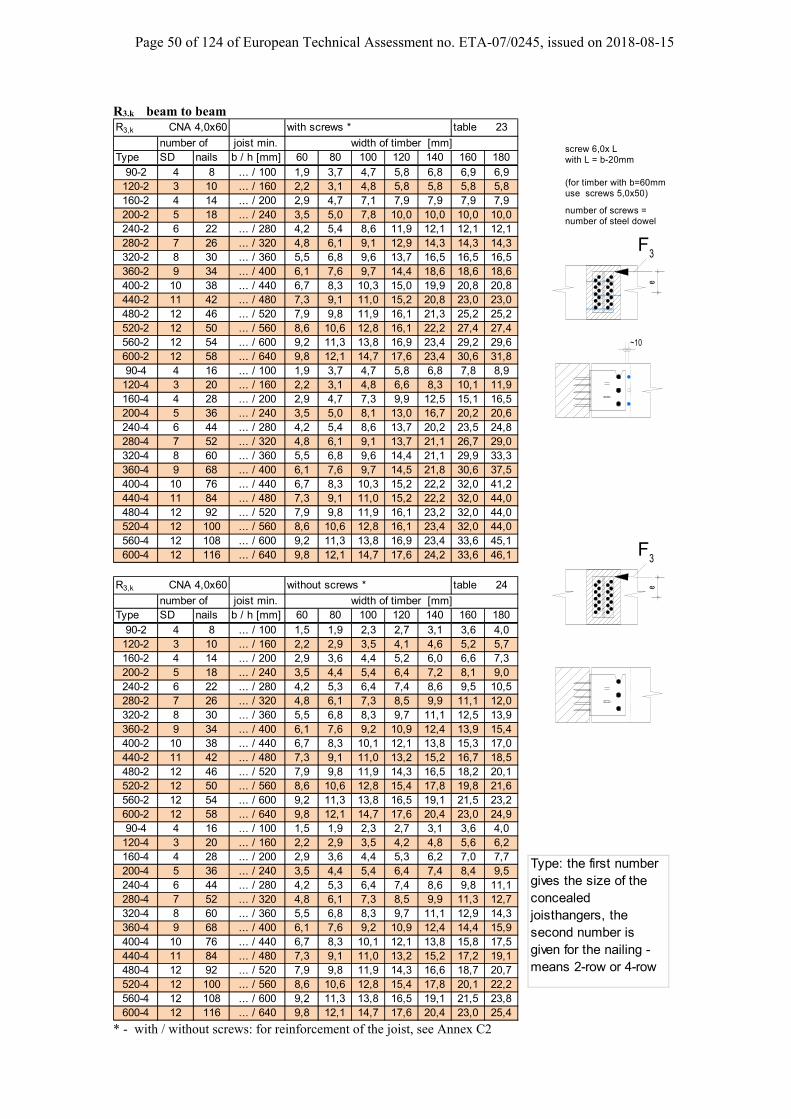
Page 50 of 124 of European Technical Assessment no. ETA-07/0245, issued on 2018-08-15
R3.k beam to beam R3,k CNA 4,0x60 with screws * table 23
number of joist min. Type SD nails b / h [mm] 60 80 100 120 140 160 180
90-2 4 8 ... / 100 1,9 3,7 4,7 5,8 6,8 6,9 6,9120-2 3 10 ... / 160 2,2 3,1 4,8 5,8 5,8 5,8 5,8160-2 4 14 ... / 200 2,9 4,7 7,1 7,9 7,9 7,9 7,9200-2 5 18 ... / 240 3,5 5,0 7,8 10,0 10,0 10,0 10,0240-2 6 22 ... / 280 4,2 5,4 8,6 11,9 12,1 12,1 12,1280-2 7 26 ... / 320 4,8 6,1 9,1 12,9 14,3 14,3 14,3320-2 8 30 ... / 360 5,5 6,8 9,6 13,7 16,5 16,5 16,5360-2 9 34 ... / 400 6,1 7,6 9,7 14,4 18,6 18,6 18,6400-2 10 38 ... / 440 6,7 8,3 10,3 15,0 19,9 20,8 20,8440-2 11 42 ... / 480 7,3 9,1 11,0 15,2 20,8 23,0 23,0480-2 12 46 ... / 520 7,9 9,8 11,9 16,1 21,3 25,2 25,2520-2 12 50 ... / 560 8,6 10,6 12,8 16,1 22,2 27,4 27,4560-2 12 54 ... / 600 9,2 11,3 13,8 16,9 23,4 29,2 29,6600-2 12 58 ... / 640 9,8 12,1 14,7 17,6 23,4 30,6 31,890-4 4 16 ... / 100 1,9 3,7 4,7 5,8 6,8 7,8 8,9
120-4 3 20 ... / 160 2,2 3,1 4,8 6,6 8,3 10,1 11,9160-4 4 28 ... / 200 2,9 4,7 7,3 9,9 12,5 15,1 16,5200-4 5 36 ... / 240 3,5 5,0 8,1 13,0 16,7 20,2 20,6240-4 6 44 ... / 280 4,2 5,4 8,6 13,7 20,2 23,5 24,8280-4 7 52 ... / 320 4,8 6,1 9,1 13,7 21,1 26,7 29,0320-4 8 60 ... / 360 5,5 6,8 9,6 14,4 21,1 29,9 33,3360-4 9 68 ... / 400 6,1 7,6 9,7 14,5 21,8 30,6 37,5400-4 10 76 ... / 440 6,7 8,3 10,3 15,2 22,2 32,0 41,2440-4 11 84 ... / 480 7,3 9,1 11,0 15,2 22,2 32,0 44,0480-4 12 92 ... / 520 7,9 9,8 11,9 16,1 23,2 32,0 44,0520-4 12 100 ... / 560 8,6 10,6 12,8 16,1 23,4 32,0 44,0560-4 12 108 ... / 600 9,2 11,3 13,8 16,9 23,4 33,6 45,1600-4 12 116 ... / 640 9,8 12,1 14,7 17,6 24,2 33,6 46,1
R3,k CNA 4,0x60 without screws * table 24
number of joist min. Type SD nails b / h [mm] 60 80 100 120 140 160 180
90-2 4 8 ... / 100 1,5 1,9 2,3 2,7 3,1 3,6 4,0120-2 3 10 ... / 160 2,2 2,9 3,5 4,1 4,6 5,2 5,7160-2 4 14 ... / 200 2,9 3,6 4,4 5,2 6,0 6,6 7,3200-2 5 18 ... / 240 3,5 4,4 5,4 6,4 7,2 8,1 9,0240-2 6 22 ... / 280 4,2 5,3 6,4 7,4 8,6 9,5 10,5280-2 7 26 ... / 320 4,8 6,1 7,3 8,5 9,9 11,1 12,0320-2 8 30 ... / 360 5,5 6,8 8,3 9,7 11,1 12,5 13,9360-2 9 34 ... / 400 6,1 7,6 9,2 10,9 12,4 13,9 15,4400-2 10 38 ... / 440 6,7 8,3 10,1 12,1 13,8 15,3 17,0440-2 11 42 ... / 480 7,3 9,1 11,0 13,2 15,2 16,7 18,5480-2 12 46 ... / 520 7,9 9,8 11,9 14,3 16,5 18,2 20,1520-2 12 50 ... / 560 8,6 10,6 12,8 15,4 17,8 19,8 21,6560-2 12 54 ... / 600 9,2 11,3 13,8 16,5 19,1 21,5 23,2600-2 12 58 ... / 640 9,8 12,1 14,7 17,6 20,4 23,0 24,990-4 4 16 ... / 100 1,5 1,9 2,3 2,7 3,1 3,6 4,0
120-4 3 20 ... / 160 2,2 2,9 3,5 4,2 4,8 5,6 6,2160-4 4 28 ... / 200 2,9 3,6 4,4 5,3 6,2 7,0 7,7200-4 5 36 ... / 240 3,5 4,4 5,4 6,4 7,4 8,4 9,5240-4 6 44 ... / 280 4,2 5,3 6,4 7,4 8,6 9,8 11,1280-4 7 52 ... / 320 4,8 6,1 7,3 8,5 9,9 11,3 12,7320-4 8 60 ... / 360 5,5 6,8 8,3 9,7 11,1 12,9 14,3360-4 9 68 ... / 400 6,1 7,6 9,2 10,9 12,4 14,4 15,9400-4 10 76 ... / 440 6,7 8,3 10,1 12,1 13,8 15,8 17,5440-4 11 84 ... / 480 7,3 9,1 11,0 13,2 15,2 17,2 19,1480-4 12 92 ... / 520 7,9 9,8 11,9 14,3 16,6 18,7 20,7520-4 12 100 ... / 560 8,6 10,6 12,8 15,4 17,8 20,1 22,2560-4 12 108 ... / 600 9,2 11,3 13,8 16,5 19,1 21,5 23,8600-4 12 116 ... / 640 9,8 12,1 14,7 17,6 20,4 23,0 25,4
width of timber [mm]
width of timber [mm]
* - with / without screws: for reinforcement of the joist, see Annex C2
Type: the first number gives the size of the concealed joisthangers, the second number is given for the nailing - means 2-row or 4-row
F 3
e
~10
screw 6,0x L
number of screws =
with L = b-20mm
number of steel dowel
(for timber with b=60mmuse screws 5,0x50)
F 3
e

Page 51 of 124 of European Technical Assessment no. ETA-07/0245, issued on 2018-08-15
R3.k beam to beam R3,k CSA 5,0x50 with screws * table 25
number of joist min. Type SD nails b / h [mm] 60 80 100 120 140 160 180
90-2 4 8 ... / 100 1,9 3,7 4,7 5,8 6,8 7,3 7,3120-2 3 10 ... / 160 2,2 3,1 4,8 6,2 6,2 6,2 6,2160-2 4 14 ... / 200 2,9 4,7 7,3 8,4 8,4 8,4 8,4200-2 5 18 ... / 240 3,5 5,0 8,1 10,6 10,6 10,6 10,6240-2 6 22 ... / 280 4,2 5,4 8,6 12,4 12,9 12,9 12,9280-2 7 26 ... / 320 4,8 6,1 9,1 13,4 15,2 15,2 15,2320-2 8 30 ... / 360 5,5 6,8 9,6 14,4 17,6 17,6 17,6360-2 9 34 ... / 400 6,1 7,6 9,7 14,5 19,3 19,9 19,9400-2 10 38 ... / 440 6,7 8,3 10,3 15,2 20,6 22,2 22,2440-2 11 42 ... / 480 7,3 9,1 11,0 15,2 21,6 24,6 24,6480-2 12 46 ... / 520 7,9 9,8 11,9 16,1 22,2 26,9 26,9520-2 12 50 ... / 560 8,6 10,6 12,8 16,1 23,4 29,2 29,3560-2 12 54 ... / 600 9,2 11,3 13,8 16,9 23,4 30,6 31,6600-2 12 58 ... / 640 9,8 12,1 14,7 17,6 24,2 31,4 34,090-4 4 16 ... / 100 1,9 3,7 4,7 5,8 6,8 7,8 8,9
120-4 3 20 ... / 160 2,2 3,1 4,8 6,6 8,3 10,1 11,9160-4 4 28 ... / 200 2,9 4,7 7,3 9,9 12,5 15,1 17,6200-4 5 36 ... / 240 3,5 5,0 8,1 13,0 16,7 20,2 22,0240-4 6 44 ... / 280 4,2 5,4 8,6 13,7 20,2 23,5 26,4280-4 7 52 ... / 320 4,8 6,1 9,1 13,7 21,1 26,7 30,2320-4 8 60 ... / 360 5,5 6,8 9,6 14,4 21,1 29,9 33,9360-4 9 68 ... / 400 6,1 7,6 9,7 14,5 21,8 30,6 37,5400-4 10 76 ... / 440 6,7 8,3 10,3 15,2 22,2 32,0 41,2440-4 11 84 ... / 480 7,3 9,1 11,0 15,2 22,2 32,0 44,0480-4 12 92 ... / 520 7,9 9,8 11,9 16,1 23,2 32,0 44,0520-4 12 100 ... / 560 8,6 10,6 12,8 16,1 23,4 32,0 44,0560-4 12 108 ... / 600 9,2 11,3 13,8 16,9 23,4 33,6 45,1600-4 12 116 ... / 640 9,8 12,1 14,7 17,6 24,2 33,6 46,1
R3,k CSA 5,0x50 without screws * table 26
number of joist min. Type SD nails b / h [mm] 60 80 100 120 140 160 180
90-2 4 8 ... / 100 1,5 1,9 2,3 2,7 3,1 3,6 4,0120-2 3 10 ... / 160 2,2 2,9 3,5 4,2 4,8 5,4 5,9160-2 4 14 ... / 200 2,9 3,6 4,4 5,3 6,2 6,9 7,5200-2 5 18 ... / 240 3,5 4,4 5,4 6,4 7,4 8,4 9,3240-2 6 22 ... / 280 4,2 5,3 6,4 7,4 8,6 9,8 10,8280-2 7 26 ... / 320 4,8 6,1 7,3 8,5 9,9 11,3 12,6320-2 8 30 ... / 360 5,5 6,8 8,3 9,7 11,1 12,9 14,3360-2 9 34 ... / 400 6,1 7,6 9,2 10,9 12,4 14,4 15,9400-2 10 38 ... / 440 6,7 8,3 10,1 12,1 13,8 15,8 17,5440-2 11 42 ... / 480 7,3 9,1 11,0 13,2 15,2 17,2 19,1480-2 12 46 ... / 520 7,9 9,8 11,9 14,3 16,6 18,7 20,7520-2 12 50 ... / 560 8,6 10,6 12,8 15,4 17,8 20,1 22,2560-2 12 54 ... / 600 9,2 11,3 13,8 16,5 19,1 21,5 23,8600-2 12 58 ... / 640 9,8 12,1 14,7 17,6 20,4 23,0 25,490-4 4 16 ... / 100 1,5 1,9 2,3 2,7 3,1 3,6 4,0
120-4 3 20 ... / 160 2,2 2,9 3,5 4,2 4,8 5,6 6,2160-4 4 28 ... / 200 2,9 3,6 4,4 5,3 6,2 7,0 7,7200-4 5 36 ... / 240 3,5 4,4 5,4 6,4 7,4 8,4 9,5240-4 6 44 ... / 280 4,2 5,3 6,4 7,4 8,6 9,8 11,1280-4 7 52 ... / 320 4,8 6,1 7,3 8,5 9,9 11,3 12,7320-4 8 60 ... / 360 5,5 6,8 8,3 9,7 11,1 12,9 14,3360-4 9 68 ... / 400 6,1 7,6 9,2 10,9 12,4 14,4 15,9400-4 10 76 ... / 440 6,7 8,3 10,1 12,1 13,8 15,8 17,5440-4 11 84 ... / 480 7,3 9,1 11,0 13,2 15,2 17,2 19,1480-4 12 92 ... / 520 7,9 9,8 11,9 14,3 16,6 18,7 20,7520-4 12 100 ... / 560 8,6 10,6 12,8 15,4 17,8 20,1 22,2560-4 12 108 ... / 600 9,2 11,3 13,8 16,5 19,1 21,5 23,8600-4 12 116 ... / 640 9,8 12,1 14,7 17,6 20,4 23,0 25,4
width of timber [mm]
width of timber [mm]
* - with / without screws: for reinforcement of the joist, see Annex C2
Type: the first number gives the size of the concealed joisthangers, the second number is given for the nailing - means 2-row or 4-row
F 3
e
~10
screw 6,0x L
number of screws =
with L = b-20mm
number of steel dowel
(for timber with b=60mmuse screws 5,0x50)
F 3
e

Page 52 of 124 of European Technical Assessment no. ETA-07/0245, issued on 2018-08-15
R3.k beam to column R3,k CNA 4,0x50 with screws * table 27
number of joist min. Type SD nails b / h [mm] 60 80 100 120 140 160 180
120-2 3 6 ... / 160 1,8 3,1 4,1 4,1 4,1 4,1 4,1160-2 4 8 ... / 200 2,4 3,8 5,3 5,3 5,3 5,3 5,3200-2 5 10 ... / 240 2,9 4,2 6,3 6,3 6,3 6,3 6,3240-2 6 12 ... / 280 3,4 4,4 7,0 7,4 7,4 7,4 7,4280-2 7 14 ... / 320 3,9 5,0 7,3 8,5 8,5 8,5 8,5320-2 8 16 ... / 360 4,4 5,7 7,7 9,6 9,6 9,6 9,6360-2 9 18 ... / 400 5,0 6,3 8,1 10,7 10,7 10,7 10,7400-2 10 20 ... / 440 5,5 6,9 8,6 11,6 11,8 11,8 11,8440-2 11 22 ... / 480 6,1 7,6 9,4 12,2 12,9 12,9 12,9480-2 12 24 ... / 520 6,6 8,3 10,2 12,5 14,0 14,0 14,0520-2 12 26 ... / 560 7,1 9,0 11,0 13,0 15,1 15,1 15,1560-2 12 28 ... / 600 7,6 9,6 11,8 13,9 16,2 16,2 16,2600-2 12 30 ... / 640 8,1 10,3 12,6 14,8 17,3 17,3 17,3120-4 3 12 ... / 160 2,2 3,1 4,8 6,6 8,3 8,8 8,8160-4 4 16 ... / 200 2,9 4,4 7,3 9,9 11,1 11,1 11,1200-4 5 20 ... / 240 3,5 4,4 8,1 12,4 12,9 12,9 12,9240-4 6 24 ... / 280 4,2 5,3 8,6 13,1 15,1 15,1 15,1280-4 7 28 ... / 320 4,8 6,1 9,1 13,7 17,2 17,2 17,2320-4 8 32 ... / 360 5,5 6,8 9,1 14,4 19,3 19,4 19,4360-4 9 36 ... / 400 6,1 7,6 9,2 14,5 20,2 21,5 21,5400-4 10 40 ... / 440 6,7 8,3 10,1 15,2 21,1 23,7 23,7440-4 11 44 ... / 480 7,3 9,1 11,0 15,2 22,2 25,9 25,9480-4 12 48 ... / 520 7,9 9,8 11,9 16,1 23,2 28,1 28,1520-4 12 52 ... / 560 8,6 10,6 12,8 16,1 23,4 29,2 30,3560-4 12 56 ... / 600 9,2 11,3 13,8 16,5 23,4 30,6 32,5600-4 12 60 ... / 640 9,8 12,1 14,7 17,6 24,2 32,0 34,7
R3,k CNA 4,0x50 without screws * table 28
number of joist min. Type SD nails b / h [mm] 60 80 100 120 140 160 180
120-2 3 6 ... / 160 1,8 2,4 3,0 3,6 4,1 4,1 4,1160-2 4 8 ... / 200 2,4 3,1 3,8 4,6 5,2 5,3 5,3200-2 5 10 ... / 240 2,9 3,8 4,6 5,5 6,2 6,3 6,3240-2 6 12 ... / 280 3,4 4,4 5,5 6,5 7,3 7,4 7,4280-2 7 14 ... / 320 3,9 5,0 6,3 7,4 8,3 8,5 8,5320-2 8 16 ... / 360 4,4 5,7 7,1 8,3 9,5 9,6 9,6360-2 9 18 ... / 400 5,0 6,3 7,8 9,3 10,6 10,7 10,7400-2 10 20 ... / 440 5,5 6,9 8,6 10,2 11,6 11,8 11,8440-2 11 22 ... / 480 6,1 7,6 9,4 11,1 12,7 12,9 12,9480-2 12 24 ... / 520 6,6 8,3 10,2 12,1 13,8 14,0 14,0520-2 12 26 ... / 560 7,1 9,0 11,0 13,0 14,8 15,1 15,1560-2 12 28 ... / 600 7,6 9,6 11,8 13,9 15,9 16,2 16,2600-2 12 30 ... / 640 8,1 10,3 12,6 14,8 16,9 17,3 17,3120-4 3 12 ... / 160 2,2 2,9 3,5 4,2 4,8 5,6 6,2160-4 4 16 ... / 200 2,9 3,6 4,4 5,3 6,2 7,0 7,7200-4 5 20 ... / 240 3,5 4,4 5,4 6,4 7,4 8,4 9,5240-4 6 24 ... / 280 4,2 5,3 6,4 7,4 8,6 9,8 11,1280-4 7 28 ... / 320 4,8 6,1 7,3 8,5 9,9 11,3 12,7320-4 8 32 ... / 360 5,5 6,8 8,3 9,7 11,1 12,9 14,3360-4 9 36 ... / 400 6,1 7,6 9,2 10,9 12,4 14,4 15,9400-4 10 40 ... / 440 6,7 8,3 10,1 12,1 13,8 15,8 17,5440-4 11 44 ... / 480 7,3 9,1 11,0 13,2 15,2 17,2 19,1480-4 12 48 ... / 520 7,9 9,8 11,9 14,3 16,6 18,7 20,7520-4 12 52 ... / 560 8,6 10,6 12,8 15,4 17,8 20,1 22,2560-4 12 56 ... / 600 9,2 11,3 13,8 16,5 19,1 21,5 23,8600-4 12 60 ... / 640 9,8 12,1 14,7 17,6 20,4 23,0 25,4
width of timber [mm]
width of timber [mm]
* - with / without screws: for reinforcement of the joist, see Annex C2
Type: the first number gives the size of the concealed joisthangers, the second number is given for the nailing - means 2-row or 4-row
F 3
screw 6,0x L
number of screws =
with L = b-20mm
number of steel dowel
(for timber with b=60mmuse screws 5,0x50)
~10
3F

Page 53 of 124 of European Technical Assessment no. ETA-07/0245, issued on 2018-08-15
R3.k beam to column
R3,k CNA 4,0x60 with screws * table 29
number of joist min. Type SD nails b / h [mm] 60 80 100 120 140 160 180
120-2 3 6 ... / 160 2,0 3,1 4,4 4,4 4,4 4,4 4,4160-2 4 8 ... / 200 2,5 4,0 5,6 5,6 5,6 5,6 5,6200-2 5 10 ... / 240 3,2 4,4 6,6 6,7 6,7 6,7 6,7240-2 6 12 ... / 280 3,8 4,6 7,2 7,9 7,9 7,9 7,9280-2 7 14 ... / 320 4,3 5,4 7,7 9,0 9,0 9,0 9,0320-2 8 16 ... / 360 4,9 6,1 8,1 10,2 10,2 10,2 10,2360-2 9 18 ... / 400 5,4 6,9 8,6 11,4 11,4 11,4 11,4400-2 10 20 ... / 440 5,9 7,6 9,0 12,1 12,6 12,6 12,6440-2 11 22 ... / 480 6,5 8,2 9,8 12,6 13,7 13,7 13,7480-2 12 24 ... / 520 7,0 8,9 10,6 13,0 14,9 14,9 14,9520-2 12 26 ... / 560 7,6 9,6 11,4 13,7 16,1 16,1 16,1560-2 12 28 ... / 600 8,1 10,3 12,2 14,4 17,3 17,3 17,3600-2 12 30 ... / 640 8,7 11,0 13,0 15,3 18,4 18,4 18,4120-4 3 12 ... / 160 2,2 3,1 4,8 6,6 8,3 9,4 9,4160-4 4 16 ... / 200 2,9 4,4 7,3 9,9 11,8 11,8 11,8200-4 5 20 ... / 240 3,5 4,4 8,1 12,8 13,7 13,7 13,7240-4 6 24 ... / 280 4,2 5,3 8,6 13,7 16,1 16,1 16,1280-4 7 28 ... / 320 4,8 6,1 9,1 13,7 18,3 18,3 18,3320-4 8 32 ... / 360 5,5 6,8 9,1 14,4 20,2 20,7 20,7360-4 9 36 ... / 400 6,1 7,6 9,2 14,5 21,1 22,9 22,9400-4 10 40 ... / 440 6,7 8,3 10,1 15,2 22,2 25,3 25,3440-4 11 44 ... / 480 7,3 9,1 11,0 15,2 22,2 27,6 27,6480-4 12 48 ... / 520 7,9 9,8 11,9 16,1 23,2 29,2 30,0520-4 12 52 ... / 560 8,6 10,6 12,8 16,1 23,4 30,6 32,3560-4 12 56 ... / 600 9,2 11,3 13,8 16,5 23,4 32,0 34,6600-4 12 60 ... / 640 9,8 12,1 14,7 17,6 24,2 33,6 37,0
R3,k CNA 4,0x60 without screws * table 30
number of joist min. Type SD nails b / h [mm] 60 80 100 120 140 160 180
120-2 3 6 ... / 160 2,0 2,6 3,1 3,7 4,2 4,4 4,4160-2 4 8 ... / 200 2,5 3,3 4,0 4,7 5,3 5,6 5,6200-2 5 10 ... / 240 3,2 3,9 4,9 5,7 6,4 6,7 6,7240-2 6 12 ... / 280 3,8 4,6 5,7 6,7 7,5 7,9 7,9280-2 7 14 ... / 320 4,3 5,4 6,5 7,7 8,7 9,0 9,0320-2 8 16 ... / 360 4,9 6,1 7,3 8,6 9,8 10,2 10,2360-2 9 18 ... / 400 5,4 6,9 8,1 9,6 10,9 11,4 11,4400-2 10 20 ... / 440 5,9 7,6 9,0 10,5 12,0 12,6 12,6440-2 11 22 ... / 480 6,5 8,2 9,8 11,5 13,1 13,7 13,7480-2 12 24 ... / 520 7,0 8,9 10,6 12,4 14,2 14,9 14,9520-2 12 26 ... / 560 7,6 9,6 11,4 13,4 15,3 16,1 16,1560-2 12 28 ... / 600 8,1 10,3 12,2 14,4 16,3 17,3 17,3600-2 12 30 ... / 640 8,7 11,0 13,0 15,3 17,4 18,4 18,4120-4 3 12 ... / 160 2,2 2,9 3,5 4,2 4,8 5,6 6,2160-4 4 16 ... / 200 2,9 3,6 4,4 5,3 6,2 7,0 7,7200-4 5 20 ... / 240 3,5 4,4 5,4 6,4 7,4 8,4 9,5240-4 6 24 ... / 280 4,2 5,3 6,4 7,4 8,6 9,8 11,1280-4 7 28 ... / 320 4,8 6,1 7,3 8,5 9,9 11,3 12,7320-4 8 32 ... / 360 5,5 6,8 8,3 9,7 11,1 12,9 14,3360-4 9 36 ... / 400 6,1 7,6 9,2 10,9 12,4 14,4 15,9400-4 10 40 ... / 440 6,7 8,3 10,1 12,1 13,8 15,8 17,5440-4 11 44 ... / 480 7,3 9,1 11,0 13,2 15,2 17,2 19,1480-4 12 48 ... / 520 7,9 9,8 11,9 14,3 16,6 18,7 20,7520-4 12 52 ... / 560 8,6 10,6 12,8 15,4 17,8 20,1 22,2560-4 12 56 ... / 600 9,2 11,3 13,8 16,5 19,1 21,5 23,8600-4 12 60 ... / 640 9,8 12,1 14,7 17,6 20,4 23,0 25,4
width of timber [mm]
width of timber [mm]
* - with / without screws: for reinforcement of the joist, see Annex C2
Type: the first number gives the size of the concealed joisthangers, the second number is given for the nailing - means 2-row or 4-row
F 3
screw 6,0x L
number of screws =
with L = b-20mm
number of steel dowel
(for timber with b=60mmuse screws 5,0x50)
~10
3F
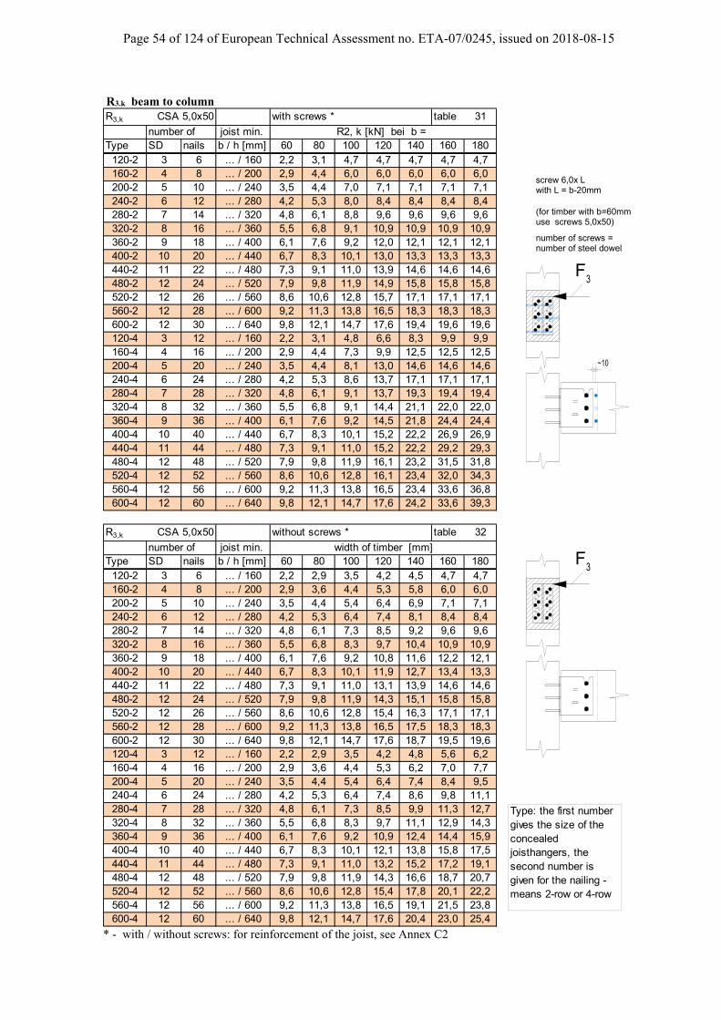
Page 54 of 124 of European Technical Assessment no. ETA-07/0245, issued on 2018-08-15
R3.k beam to column R3,k CSA 5,0x50 with screws * table 31
number of joist min. R2, k [kN] bei b =Type SD nails b / h [mm] 60 80 100 120 140 160 180
120-2 3 6 ... / 160 2,2 3,1 4,7 4,7 4,7 4,7 4,7160-2 4 8 ... / 200 2,9 4,4 6,0 6,0 6,0 6,0 6,0200-2 5 10 ... / 240 3,5 4,4 7,0 7,1 7,1 7,1 7,1240-2 6 12 ... / 280 4,2 5,3 8,0 8,4 8,4 8,4 8,4280-2 7 14 ... / 320 4,8 6,1 8,8 9,6 9,6 9,6 9,6320-2 8 16 ... / 360 5,5 6,8 9,1 10,9 10,9 10,9 10,9360-2 9 18 ... / 400 6,1 7,6 9,2 12,0 12,1 12,1 12,1400-2 10 20 ... / 440 6,7 8,3 10,1 13,0 13,3 13,3 13,3440-2 11 22 ... / 480 7,3 9,1 11,0 13,9 14,6 14,6 14,6480-2 12 24 ... / 520 7,9 9,8 11,9 14,9 15,8 15,8 15,8520-2 12 26 ... / 560 8,6 10,6 12,8 15,7 17,1 17,1 17,1560-2 12 28 ... / 600 9,2 11,3 13,8 16,5 18,3 18,3 18,3600-2 12 30 ... / 640 9,8 12,1 14,7 17,6 19,4 19,6 19,6120-4 3 12 ... / 160 2,2 3,1 4,8 6,6 8,3 9,9 9,9160-4 4 16 ... / 200 2,9 4,4 7,3 9,9 12,5 12,5 12,5200-4 5 20 ... / 240 3,5 4,4 8,1 13,0 14,6 14,6 14,6240-4 6 24 ... / 280 4,2 5,3 8,6 13,7 17,1 17,1 17,1280-4 7 28 ... / 320 4,8 6,1 9,1 13,7 19,3 19,4 19,4320-4 8 32 ... / 360 5,5 6,8 9,1 14,4 21,1 22,0 22,0360-4 9 36 ... / 400 6,1 7,6 9,2 14,5 21,8 24,4 24,4400-4 10 40 ... / 440 6,7 8,3 10,1 15,2 22,2 26,9 26,9440-4 11 44 ... / 480 7,3 9,1 11,0 15,2 22,2 29,2 29,3480-4 12 48 ... / 520 7,9 9,8 11,9 16,1 23,2 31,5 31,8520-4 12 52 ... / 560 8,6 10,6 12,8 16,1 23,4 32,0 34,3560-4 12 56 ... / 600 9,2 11,3 13,8 16,5 23,4 33,6 36,8600-4 12 60 ... / 640 9,8 12,1 14,7 17,6 24,2 33,6 39,3
R3,k CSA 5,0x50 without screws * table 32
number of joist min. Type SD nails b / h [mm] 60 80 100 120 140 160 180
120-2 3 6 ... / 160 2,2 2,9 3,5 4,2 4,5 4,7 4,7160-2 4 8 ... / 200 2,9 3,6 4,4 5,3 5,8 6,0 6,0200-2 5 10 ... / 240 3,5 4,4 5,4 6,4 6,9 7,1 7,1240-2 6 12 ... / 280 4,2 5,3 6,4 7,4 8,1 8,4 8,4280-2 7 14 ... / 320 4,8 6,1 7,3 8,5 9,2 9,6 9,6320-2 8 16 ... / 360 5,5 6,8 8,3 9,7 10,4 10,9 10,9360-2 9 18 ... / 400 6,1 7,6 9,2 10,8 11,6 12,2 12,1400-2 10 20 ... / 440 6,7 8,3 10,1 11,9 12,7 13,4 13,3440-2 11 22 ... / 480 7,3 9,1 11,0 13,1 13,9 14,6 14,6480-2 12 24 ... / 520 7,9 9,8 11,9 14,3 15,1 15,8 15,8520-2 12 26 ... / 560 8,6 10,6 12,8 15,4 16,3 17,1 17,1560-2 12 28 ... / 600 9,2 11,3 13,8 16,5 17,5 18,3 18,3600-2 12 30 ... / 640 9,8 12,1 14,7 17,6 18,7 19,5 19,6120-4 3 12 ... / 160 2,2 2,9 3,5 4,2 4,8 5,6 6,2160-4 4 16 ... / 200 2,9 3,6 4,4 5,3 6,2 7,0 7,7200-4 5 20 ... / 240 3,5 4,4 5,4 6,4 7,4 8,4 9,5240-4 6 24 ... / 280 4,2 5,3 6,4 7,4 8,6 9,8 11,1280-4 7 28 ... / 320 4,8 6,1 7,3 8,5 9,9 11,3 12,7320-4 8 32 ... / 360 5,5 6,8 8,3 9,7 11,1 12,9 14,3360-4 9 36 ... / 400 6,1 7,6 9,2 10,9 12,4 14,4 15,9400-4 10 40 ... / 440 6,7 8,3 10,1 12,1 13,8 15,8 17,5440-4 11 44 ... / 480 7,3 9,1 11,0 13,2 15,2 17,2 19,1480-4 12 48 ... / 520 7,9 9,8 11,9 14,3 16,6 18,7 20,7520-4 12 52 ... / 560 8,6 10,6 12,8 15,4 17,8 20,1 22,2560-4 12 56 ... / 600 9,2 11,3 13,8 16,5 19,1 21,5 23,8600-4 12 60 ... / 640 9,8 12,1 14,7 17,6 20,4 23,0 25,4
width of timber [mm]
* - with / without screws: for reinforcement of the joist, see Annex C2
Type: the first number gives the size of the concealed joisthangers, the second number is given for the nailing - means 2-row or 4-row
F 3
screw 6,0x L
number of screws =
with L = b-20mm
number of steel dowel
(for timber with b=60mmuse screws 5,0x50)
~10
3F
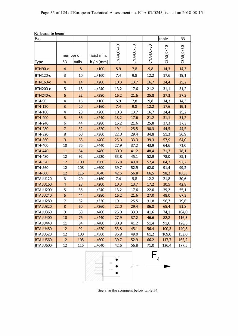
Page 55 of 124 of European Technical Assessment no. ETA-07/0245, issued on 2018-08-15
R4 beam to beam R4,k table 33
joist min.
Type SD nails b / h [mm]
BTN90‐c 4 8 …/100 5,9 7,8 9,8 14,3 14,3
BTN120‐c 3 10 …/160 7,4 9,8 12,2 17,6 19,1
BTN160‐c 4 14 …/200 10,3 13,7 16,7 24,4 25,2
BTN200‐c 5 18 …/240 13,2 17,6 21,2 31,1 31,2
BTN240‐c 6 22 …/280 16,2 21,6 25,8 37,3 37,3
BT4‐90 4 16 …/100 5,9 7,8 9,8 14,3 14,3
BT4‐120 3 20 …/160 7,4 9,8 12,2 17,6 19,1
BT4‐160 4 28 …/200 10,3 13,7 16,7 24,4 25,2
BT4‐200 5 36 …/240 13,2 17,6 21,2 31,1 31,2
BT4‐240 6 44 …/280 16,2 21,6 25,8 37,3 37,3
BT4‐280 7 52 …/320 19,1 25,5 30,3 44,5 44,5
BT4‐320 8 60 …/360 22,0 29,4 34,8 51,2 56,9
BT4‐360 9 68 …/400 25,0 33,3 39,3 57,9 64,0
BT4‐400 10 76 …/440 27,9 37,2 43,9 64,6 71,0
BT4‐440 11 84 …/480 30,9 41,2 48,4 71,3 78,1
BT4‐480 12 92 …/520 33,8 45,1 52,9 78,0 85,1
BT4‐520 12 100 …/560 36,8 49,0 57,4 84,7 92,2
BT4‐560 12 108 …/600 39,7 52,9 62,0 91,4 99,2
BT4‐600 12 116 …/640 42,6 56,8 66,5 98,2 106,3
BTALU120 3 20 …/160 7,4 9,8 12,2 21,8 30,6
BTALU160 4 28 …/200 10,3 13,7 17,2 30,5 42,8
BTALU200 5 36 …/240 13,2 17,6 22,0 39,2 55,1
BTALU240 6 44 …/280 16,2 21,6 27,0 48,0 67,3
BTALU280 7 52 …/320 19,1 25,5 31,8 56,7 79,6
BTALU320 8 60 …/360 22,0 29,4 36,8 65,4 91,8
BTALU360 9 68 …/400 25,0 33,3 41,6 74,1 104,0
BTALU400 10 76 …/440 27,9 37,2 46,6 82,8 116,3
BTALU440 11 84 …/480 30,9 41,2 51,4 91,6 128,5
BTALU480 12 92 …/520 33,8 45,1 56,4 100,3 140,8
BTALU520 12 100 …/560 36,8 49,0 61,2 109,0 153,0
BTALU560 12 108 …/600 39,7 52,9 66,2 117,7 165,2
BTALU600 12 116 …/640 42,6 56,8 71,0 126,4 177,5
number of
CNA4,0x4
0
CNA4,0x5
0
CNA4,0x6
0
CSA
5,0x4
0
CSA
5,0x5
0
.
F 4
See also the comment below table 34
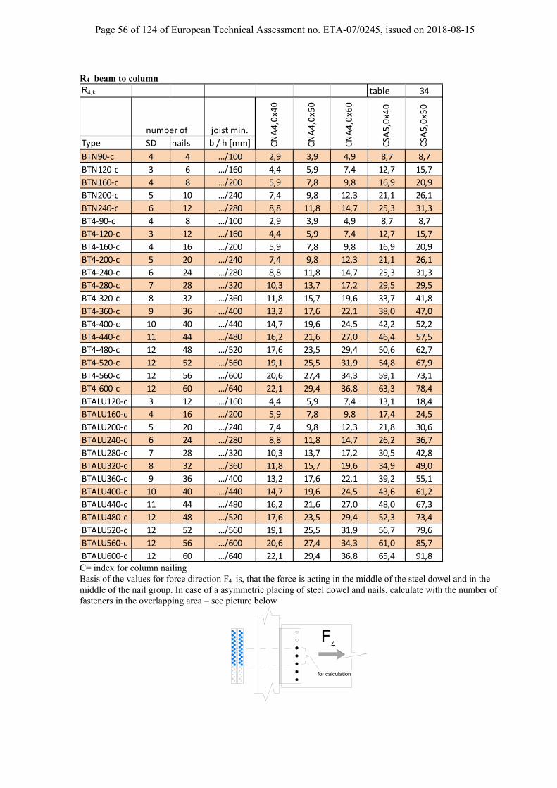
Page 56 of 124 of European Technical Assessment no. ETA-07/0245, issued on 2018-08-15
R4 beam to column R4,k table 34
joist min.
Type SD nails b / h [mm]
BTN90‐c 4 4 …/100 2,9 3,9 4,9 8,7 8,7
BTN120‐c 3 6 …/160 4,4 5,9 7,4 12,7 15,7
BTN160‐c 4 8 …/200 5,9 7,8 9,8 16,9 20,9
BTN200‐c 5 10 …/240 7,4 9,8 12,3 21,1 26,1
BTN240‐c 6 12 …/280 8,8 11,8 14,7 25,3 31,3
BT4‐90‐c 4 8 …/100 2,9 3,9 4,9 8,7 8,7
BT4‐120‐c 3 12 …/160 4,4 5,9 7,4 12,7 15,7
BT4‐160‐c 4 16 …/200 5,9 7,8 9,8 16,9 20,9
BT4‐200‐c 5 20 …/240 7,4 9,8 12,3 21,1 26,1
BT4‐240‐c 6 24 …/280 8,8 11,8 14,7 25,3 31,3
BT4‐280‐c 7 28 …/320 10,3 13,7 17,2 29,5 29,5
BT4‐320‐c 8 32 …/360 11,8 15,7 19,6 33,7 41,8
BT4‐360‐c 9 36 …/400 13,2 17,6 22,1 38,0 47,0
BT4‐400‐c 10 40 …/440 14,7 19,6 24,5 42,2 52,2
BT4‐440‐c 11 44 …/480 16,2 21,6 27,0 46,4 57,5
BT4‐480‐c 12 48 …/520 17,6 23,5 29,4 50,6 62,7
BT4‐520‐c 12 52 …/560 19,1 25,5 31,9 54,8 67,9
BT4‐560‐c 12 56 …/600 20,6 27,4 34,3 59,1 73,1
BT4‐600‐c 12 60 …/640 22,1 29,4 36,8 63,3 78,4
BTALU120‐c 3 12 …/160 4,4 5,9 7,4 13,1 18,4
BTALU160‐c 4 16 …/200 5,9 7,8 9,8 17,4 24,5
BTALU200‐c 5 20 …/240 7,4 9,8 12,3 21,8 30,6
BTALU240‐c 6 24 …/280 8,8 11,8 14,7 26,2 36,7
BTALU280‐c 7 28 …/320 10,3 13,7 17,2 30,5 42,8
BTALU320‐c 8 32 …/360 11,8 15,7 19,6 34,9 49,0
BTALU360‐c 9 36 …/400 13,2 17,6 22,1 39,2 55,1
BTALU400‐c 10 40 …/440 14,7 19,6 24,5 43,6 61,2
BTALU440‐c 11 44 …/480 16,2 21,6 27,0 48,0 67,3
BTALU480‐c 12 48 …/520 17,6 23,5 29,4 52,3 73,4
BTALU520‐c 12 52 …/560 19,1 25,5 31,9 56,7 79,6
BTALU560‐c 12 56 …/600 20,6 27,4 34,3 61,0 85,7
BTALU600‐c 12 60 …/640 22,1 29,4 36,8 65,4 91,8
number of
CNA4,0x4
0
CNA4,0x5
0
CNA4,0x6
0
CSA
5,0x4
0
CSA
5,0x5
0
C= index for column nailing Basis of the values for force direction F4 is, that the force is acting in the middle of the steel dowel and in the middle of the nail group. In case of a asymmetric placing of steel dowel and nails, calculate with the number of fasteners in the overlapping area – see picture below
4F
for calculation

Page 57 of 124 of European Technical Assessment no. ETA-07/0245, issued on 2018-08-15
Force direction F4 Additional information:
- The BTALU can be used with CNA nails of a diameter of Ø4 mm with a length from 35 to 100mm and CSA screws of a diameter of Ø5 mm and a length from 35 to 50mm. Capacity of these fasteners can be found in ETA-04/0013.
- The load is located on the centre of gravity of the dowels - The dowels must be distributed equally across the whole height of the hanger. - The nails must be distributed equally across all around the dowels - For solid timber: The spacing and edge distance to the timber must respect rules given by EUROCODE 5
(EN1995-1-1 §8.6 Table 8.5) - For CLT: the spacing and edge distance to the timber must respect rules from ETA of the CLT
manufacturer. - The minimum distance between the edge of the hangers and the dowels is equal to 1,5d (d is the diameter
of the dowels) - All dowels must have the same diameter, length and yield capacity.

Page 58 of 124 of European Technical Assessment no. ETA-07/0245, issued on 2018-08-15
R1,k CNA4.0x50 4‐Row SD: Ø7 C24 Header
Dowels nails Fk nails Fk nails Fk nails Fk nails Fk nails Fk
20 11,6 20 12,7 20 13,0 20 13,0 20 13,0 20 13,0
32 15,4 32 17,8 36 20,3 36 20,3 36 20,3 36 20,3
20 14,6 20 16,3 24 19,0 24 19,0 24 19,0 24 19,0
36 20,5 36 23,8 40 27,1 40 27,1 40 27,1 40 27,1
24 20,1 24 22,4 28 25,7 28 25,7 28 25,7 28 25,7
40 25,7 40 29,7 44 34,0 44 34,0 44 34,0 44 34,0
28 25,8 32 30,8 32 32,7 32 32,7 32 32,7 32 32,7
44 30,8 48 35,7 48 40,8 48 40,8 48 40,8 48 40,8
32 31,6 32 35,4 36 39,9 36 39,9 36 39,9 36 39,9
48 36,0 48 41,6 52 47,5 52 47,5 52 47,5 52 47,5
32 35,7 36 42,1 40 47,3 40 47,3 40 47,3 40 47,3
48 41,1 52 47,6 56 54,3 56 54,3 56 54,3 56 54,3
36 41,6 40 48,8 44 54,7 44 54,7 44 54,7 44 54,7
52 46,3 56 53,6 60 61,2 60 61,2 60 61,2 60 61,2
40 47,6 44 55,4 48 62,2 48 62,2 48 62,2 48 62,2
56 51,4 60 59,5 64 68,0 64 68,0 64 68,0 64 68,0
44 53,4 48 62,0 52 69,7 52 69,7 52 69,7 52 69,7
60 56,5 64 65,4 68 74,8 68 74,8 68 74,8 68 74,8
44 57,9 52 68,6 56 77,1 56 77,1 56 77,1 56 77,1
60 61,7 68 71,4 72 81,6 72 81,6 72 81,6 72 81,6
R1,k CNA4.0x60 4‐Row SD: Ø7 C24 Header
Dowels nails Fk nails Fk nails Fk nails Fk nails Fk nails Fk
20 14,4 20 14,4 20 14,4 20 14,4 20 14,4 20 14,4
28 19,7 28 19,7 32 20,3 32 20,3 32 20,3 32 20,3
20 18,1 20 18,1 20 18,1 20 18,1 20 18,1 20 18,1
36 26,7 36 26,7 36 27,1 36 27,1 36 27,1 36 27,1
24 24,9 24 24,9 24 24,9 24 24,9 24 24,9 24 24,9
40 33,9 40 33,9 40 33,9 40 33,9 40 33,9 40 33,9
28 32,2 28 32,2 28 32,2 28 32,2 28 32,2 28 32,2
44 40,8 44 40,8 44 40,8 44 40,8 44 40,8 44 40,8
32 39,6 32 39,6 32 39,6 32 39,6 32 39,6 32 39,6
48 47,5 48 47,5 48 47,5 48 47,5 48 47,5 48 47,5
36 47,3 36 47,3 36 47,3 36 47,3 36 47,3 36 47,3
52 54,3 52 54,3 52 54,3 52 54,3 52 54,3 52 54,3
40 54,9 40 54,9 40 54,9 40 54,9 40 54,9 40 54,9
56 61,0 56 61,0 56 61,1 56 61,1 56 61,1 56 61,1
40 60,3 40 60,3 44 62,6 44 62,6 44 62,6 44 62,6
56 67,8 56 67,8 60 67,9 60 67,9 60 67,9 60 67,9
44 68,0 44 68,0 44 68,0 44 68,0 44 68,0 44 68,0
60 74,7 60 74,7 60 74,7 60 74,7 60 74,7 60 74,7
48 75,7 48 75,7 48 75,7 48 75,7 48 75,7 48 75,7
64 81,6 64 81,6 64 81,6 64 81,6 64 81,6 64 81,6
R1,k CSA5.0x50 4‐Row SD: Ø7 C24 Header
Dowels nails Fk nails Fk nails Fk nails Fk nails Fk nails Fk
20 15,4 20 17,8 20 20,3 20 20,3 20 20,3 20 20,3
20 15,4 20 17,8 20 20,3 20 20,3 20 20,3 20 20,3
20 25,3 20 25,3 20 25,3 20 25,3 20 25,3 20 25,3
20 25,3 20 25,3 24 27,1 24 27,1 24 27,1 24 27,1
20 29,1 20 29,1 20 29,1 20 29,1 20 29,1 20 29,1
24 33,1 24 33,1 28 33,9 28 33,9 28 33,9 28 33,9
20 33,1 20 33,1 20 33,1 20 33,1 20 33,1 20 33,1
28 40,6 28 40,6 32 40,7 32 40,7 32 40,7 32 40,7
20 37,4 20 37,4 20 37,4 20 37,4 20 37,4 20 37,4
32 47,6 32 47,6 32 47,6 32 47,6 32 47,6 32 47,6
20 41,7 20 41,7 20 41,7 20 41,7 20 41,7 20 41,7
36 53,5 36 53,5 36 54,3 36 54,3 36 54,3 36 54,3
20 46,0 20 46,0 24 50,3 24 50,3 24 50,3 24 50,3
36 61,0 36 61,0 40 61,1 40 61,1 40 61,1 40 61,1
24 54,7 24 54,7 24 54,7 24 54,7 24 54,7 24 54,7
40 68,0 40 68,0 40 68,0 40 68,0 40 68,0 40 68,0
28 63,3 28 63,3 28 63,3 28 63,3 28 63,3 28 63,3
44 74,2 44 74,2 44 74,7 44 74,7 44 74,7 44 74,7
28 67,4 28 67,4 28 67,4 28 67,4 28 67,4 28 67,4
44 81,5 44 81,5 44 81,5 44 81,5 44 81,5 44 81,5
9 SD
10 SD
11 SD
12 SD
Table 41
Table 40
3 SD
4 SD
5 SD
6 SD
7 SD
Width of the timber = length of the dowels (mm)
80 100 120 140 160 180
12 SD
3 SD
4 SD
5 SD
6 SD
7 SD
8 SD
80 100 120 140 160 180
9 SD
10 SD
11 SD
12 SD
Table 42
9 SD
10 SD
11 SD
Width of the timber = length of the dowels (mm)
3 SD
4 SD
5 SD
6 SD
7 SD
8 SD
Width of the timber = length of the dowels (mm)
80 100 120 140 160 180
8 SD
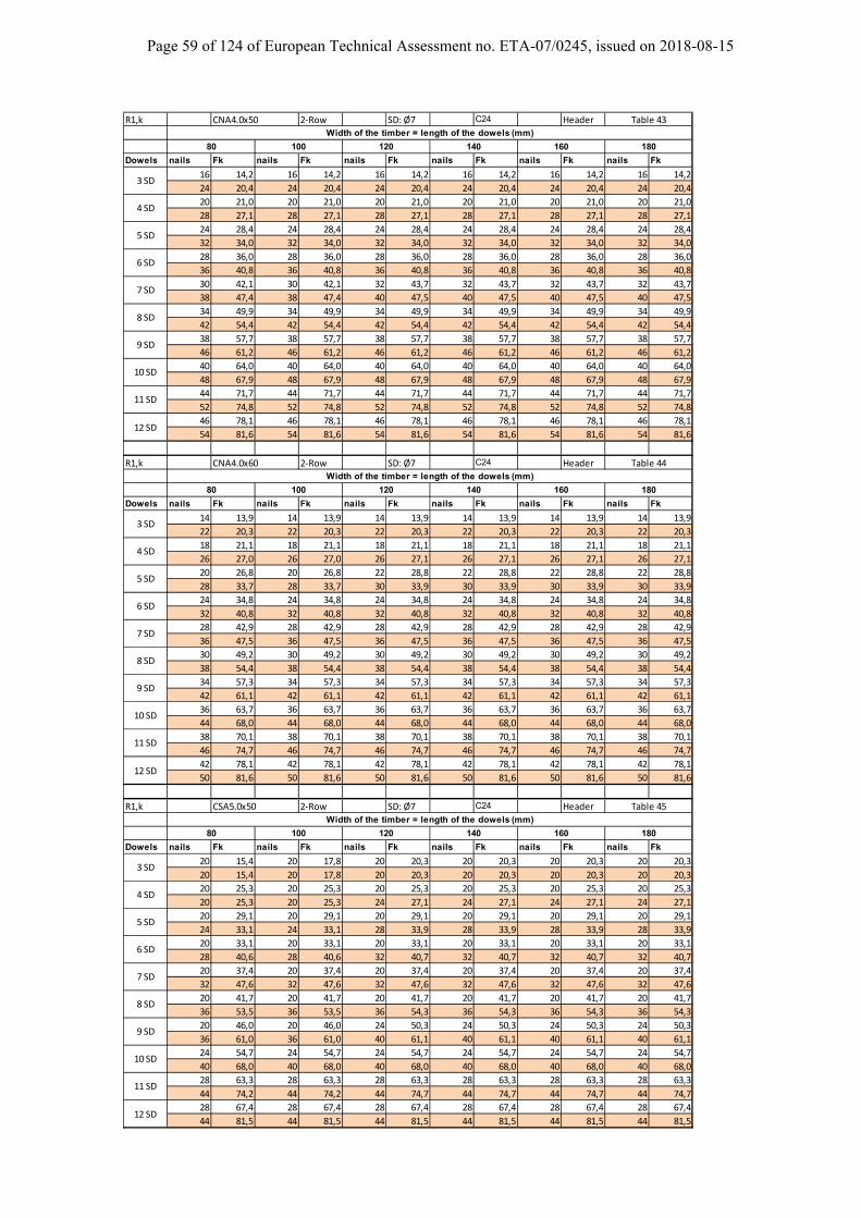
Page 59 of 124 of European Technical Assessment no. ETA-07/0245, issued on 2018-08-15
R1,k CNA4.0x50 2‐Row SD: Ø7 C24 Header
Dowels nails Fk nails Fk nails Fk nails Fk nails Fk nails Fk
16 14,2 16 14,2 16 14,2 16 14,2 16 14,2 16 14,2
24 20,4 24 20,4 24 20,4 24 20,4 24 20,4 24 20,4
20 21,0 20 21,0 20 21,0 20 21,0 20 21,0 20 21,0
28 27,1 28 27,1 28 27,1 28 27,1 28 27,1 28 27,1
24 28,4 24 28,4 24 28,4 24 28,4 24 28,4 24 28,4
32 34,0 32 34,0 32 34,0 32 34,0 32 34,0 32 34,0
28 36,0 28 36,0 28 36,0 28 36,0 28 36,0 28 36,0
36 40,8 36 40,8 36 40,8 36 40,8 36 40,8 36 40,8
30 42,1 30 42,1 32 43,7 32 43,7 32 43,7 32 43,7
38 47,4 38 47,4 40 47,5 40 47,5 40 47,5 40 47,5
34 49,9 34 49,9 34 49,9 34 49,9 34 49,9 34 49,9
42 54,4 42 54,4 42 54,4 42 54,4 42 54,4 42 54,4
38 57,7 38 57,7 38 57,7 38 57,7 38 57,7 38 57,7
46 61,2 46 61,2 46 61,2 46 61,2 46 61,2 46 61,2
40 64,0 40 64,0 40 64,0 40 64,0 40 64,0 40 64,0
48 67,9 48 67,9 48 67,9 48 67,9 48 67,9 48 67,9
44 71,7 44 71,7 44 71,7 44 71,7 44 71,7 44 71,7
52 74,8 52 74,8 52 74,8 52 74,8 52 74,8 52 74,8
46 78,1 46 78,1 46 78,1 46 78,1 46 78,1 46 78,1
54 81,6 54 81,6 54 81,6 54 81,6 54 81,6 54 81,6
R1,k CNA4.0x60 2‐Row SD: Ø7 C24 Header
Dowels nails Fk nails Fk nails Fk nails Fk nails Fk nails Fk
14 13,9 14 13,9 14 13,9 14 13,9 14 13,9 14 13,9
22 20,3 22 20,3 22 20,3 22 20,3 22 20,3 22 20,3
18 21,1 18 21,1 18 21,1 18 21,1 18 21,1 18 21,1
26 27,0 26 27,0 26 27,1 26 27,1 26 27,1 26 27,1
20 26,8 20 26,8 22 28,8 22 28,8 22 28,8 22 28,8
28 33,7 28 33,7 30 33,9 30 33,9 30 33,9 30 33,9
24 34,8 24 34,8 24 34,8 24 34,8 24 34,8 24 34,8
32 40,8 32 40,8 32 40,8 32 40,8 32 40,8 32 40,8
28 42,9 28 42,9 28 42,9 28 42,9 28 42,9 28 42,9
36 47,5 36 47,5 36 47,5 36 47,5 36 47,5 36 47,5
30 49,2 30 49,2 30 49,2 30 49,2 30 49,2 30 49,2
38 54,4 38 54,4 38 54,4 38 54,4 38 54,4 38 54,4
34 57,3 34 57,3 34 57,3 34 57,3 34 57,3 34 57,3
42 61,1 42 61,1 42 61,1 42 61,1 42 61,1 42 61,1
36 63,7 36 63,7 36 63,7 36 63,7 36 63,7 36 63,7
44 68,0 44 68,0 44 68,0 44 68,0 44 68,0 44 68,0
38 70,1 38 70,1 38 70,1 38 70,1 38 70,1 38 70,1
46 74,7 46 74,7 46 74,7 46 74,7 46 74,7 46 74,7
42 78,1 42 78,1 42 78,1 42 78,1 42 78,1 42 78,1
50 81,6 50 81,6 50 81,6 50 81,6 50 81,6 50 81,6
R1,k CSA5.0x50 2‐Row SD: Ø7 C24 Header
Dowels nails Fk nails Fk nails Fk nails Fk nails Fk nails Fk
20 15,4 20 17,8 20 20,3 20 20,3 20 20,3 20 20,3
20 15,4 20 17,8 20 20,3 20 20,3 20 20,3 20 20,3
20 25,3 20 25,3 20 25,3 20 25,3 20 25,3 20 25,3
20 25,3 20 25,3 24 27,1 24 27,1 24 27,1 24 27,1
20 29,1 20 29,1 20 29,1 20 29,1 20 29,1 20 29,1
24 33,1 24 33,1 28 33,9 28 33,9 28 33,9 28 33,9
20 33,1 20 33,1 20 33,1 20 33,1 20 33,1 20 33,1
28 40,6 28 40,6 32 40,7 32 40,7 32 40,7 32 40,7
20 37,4 20 37,4 20 37,4 20 37,4 20 37,4 20 37,4
32 47,6 32 47,6 32 47,6 32 47,6 32 47,6 32 47,6
20 41,7 20 41,7 20 41,7 20 41,7 20 41,7 20 41,7
36 53,5 36 53,5 36 54,3 36 54,3 36 54,3 36 54,3
20 46,0 20 46,0 24 50,3 24 50,3 24 50,3 24 50,3
36 61,0 36 61,0 40 61,1 40 61,1 40 61,1 40 61,1
24 54,7 24 54,7 24 54,7 24 54,7 24 54,7 24 54,7
40 68,0 40 68,0 40 68,0 40 68,0 40 68,0 40 68,0
28 63,3 28 63,3 28 63,3 28 63,3 28 63,3 28 63,3
44 74,2 44 74,2 44 74,7 44 74,7 44 74,7 44 74,7
28 67,4 28 67,4 28 67,4 28 67,4 28 67,4 28 67,4
44 81,5 44 81,5 44 81,5 44 81,5 44 81,5 44 81,5
Table 43
Width of the timber = length of the dowels (mm)
80 100 120 140 160 180
3 SD
4 SD
5 SD
6 SD
Table 44
Width of the timber = length of the dowels (mm)
80 100 120 140 160 180
7 SD
8 SD
9 SD
10 SD
11 SD
12 SD
11 SD
12 SD
Table 45
Width of the timber = length of the dowels (mm)
3 SD
4 SD
5 SD
6 SD
7 SD
8 SD
9 SD
10 SD
11 SD
12 SD
3 SD
4 SD
5 SD
6 SD
7 SD
8 SD
80 100 120 140 160 180
9 SD
10 SD
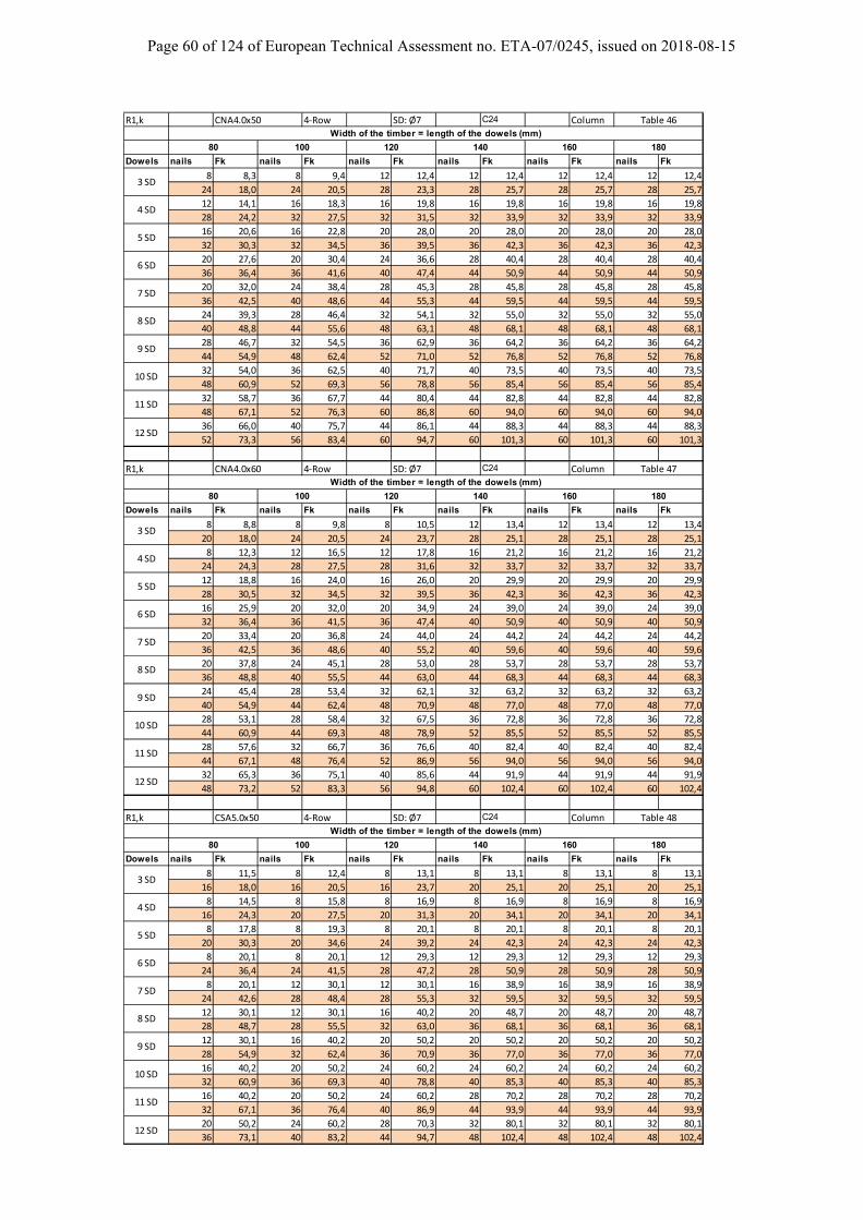
Page 60 of 124 of European Technical Assessment no. ETA-07/0245, issued on 2018-08-15
R1,k CNA4.0x50 4‐Row SD: Ø7 C24 Column
Dowels nails Fk nails Fk nails Fk nails Fk nails Fk nails Fk
8 8,3 8 9,4 12 12,4 12 12,4 12 12,4 12 12,4
24 18,0 24 20,5 28 23,3 28 25,7 28 25,7 28 25,7
12 14,1 16 18,3 16 19,8 16 19,8 16 19,8 16 19,8
28 24,2 32 27,5 32 31,5 32 33,9 32 33,9 32 33,9
16 20,6 16 22,8 20 28,0 20 28,0 20 28,0 20 28,0
32 30,3 32 34,5 36 39,5 36 42,3 36 42,3 36 42,3
20 27,6 20 30,4 24 36,6 28 40,4 28 40,4 28 40,4
36 36,4 36 41,6 40 47,4 44 50,9 44 50,9 44 50,9
20 32,0 24 38,4 28 45,3 28 45,8 28 45,8 28 45,8
36 42,5 40 48,6 44 55,3 44 59,5 44 59,5 44 59,5
24 39,3 28 46,4 32 54,1 32 55,0 32 55,0 32 55,0
40 48,8 44 55,6 48 63,1 48 68,1 48 68,1 48 68,1
28 46,7 32 54,5 36 62,9 36 64,2 36 64,2 36 64,2
44 54,9 48 62,4 52 71,0 52 76,8 52 76,8 52 76,8
32 54,0 36 62,5 40 71,7 40 73,5 40 73,5 40 73,5
48 60,9 52 69,3 56 78,8 56 85,4 56 85,4 56 85,4
32 58,7 36 67,7 44 80,4 44 82,8 44 82,8 44 82,8
48 67,1 52 76,3 60 86,8 60 94,0 60 94,0 60 94,0
36 66,0 40 75,7 44 86,1 44 88,3 44 88,3 44 88,3
52 73,3 56 83,4 60 94,7 60 101,3 60 101,3 60 101,3
R1,k CNA4.0x60 4‐Row SD: Ø7 C24 Column
Dowels nails Fk nails Fk nails Fk nails Fk nails Fk nails Fk
8 8,8 8 9,8 8 10,5 12 13,4 12 13,4 12 13,4
20 18,0 24 20,5 24 23,7 28 25,1 28 25,1 28 25,1
8 12,3 12 16,5 12 17,8 16 21,2 16 21,2 16 21,2
24 24,3 28 27,5 28 31,6 32 33,7 32 33,7 32 33,7
12 18,8 16 24,0 16 26,0 20 29,9 20 29,9 20 29,9
28 30,5 32 34,5 32 39,5 36 42,3 36 42,3 36 42,3
16 25,9 20 32,0 20 34,9 24 39,0 24 39,0 24 39,0
32 36,4 36 41,5 36 47,4 40 50,9 40 50,9 40 50,9
20 33,4 20 36,8 24 44,0 24 44,2 24 44,2 24 44,2
36 42,5 36 48,6 40 55,2 40 59,6 40 59,6 40 59,6
20 37,8 24 45,1 28 53,0 28 53,7 28 53,7 28 53,7
36 48,8 40 55,5 44 63,0 44 68,3 44 68,3 44 68,3
24 45,4 28 53,4 32 62,1 32 63,2 32 63,2 32 63,2
40 54,9 44 62,4 48 70,9 48 77,0 48 77,0 48 77,0
28 53,1 28 58,4 32 67,5 36 72,8 36 72,8 36 72,8
44 60,9 44 69,3 48 78,9 52 85,5 52 85,5 52 85,5
28 57,6 32 66,7 36 76,6 40 82,4 40 82,4 40 82,4
44 67,1 48 76,4 52 86,9 56 94,0 56 94,0 56 94,0
32 65,3 36 75,1 40 85,6 44 91,9 44 91,9 44 91,9
48 73,2 52 83,3 56 94,8 60 102,4 60 102,4 60 102,4
R1,k CSA5.0x50 4‐Row SD: Ø7 C24 Column
Dowels nails Fk nails Fk nails Fk nails Fk nails Fk nails Fk
8 11,5 8 12,4 8 13,1 8 13,1 8 13,1 8 13,1
16 18,0 16 20,5 16 23,7 20 25,1 20 25,1 20 25,1
8 14,5 8 15,8 8 16,9 8 16,9 8 16,9 8 16,9
16 24,3 20 27,5 20 31,3 20 34,1 20 34,1 20 34,1
8 17,8 8 19,3 8 20,1 8 20,1 8 20,1 8 20,1
20 30,3 20 34,6 24 39,2 24 42,3 24 42,3 24 42,3
8 20,1 8 20,1 12 29,3 12 29,3 12 29,3 12 29,3
24 36,4 24 41,5 28 47,2 28 50,9 28 50,9 28 50,9
8 20,1 12 30,1 12 30,1 16 38,9 16 38,9 16 38,9
24 42,6 28 48,4 28 55,3 32 59,5 32 59,5 32 59,5
12 30,1 12 30,1 16 40,2 20 48,7 20 48,7 20 48,7
28 48,7 28 55,5 32 63,0 36 68,1 36 68,1 36 68,1
12 30,1 16 40,2 20 50,2 20 50,2 20 50,2 20 50,2
28 54,9 32 62,4 36 70,9 36 77,0 36 77,0 36 77,0
16 40,2 20 50,2 24 60,2 24 60,2 24 60,2 24 60,2
32 60,9 36 69,3 40 78,8 40 85,3 40 85,3 40 85,3
16 40,2 20 50,2 24 60,2 28 70,2 28 70,2 28 70,2
32 67,1 36 76,4 40 86,9 44 93,9 44 93,9 44 93,9
20 50,2 24 60,2 28 70,3 32 80,1 32 80,1 32 80,1
36 73,1 40 83,2 44 94,7 48 102,4 48 102,4 48 102,4
Table 46
Width of the timber = length of the dowels (mm)
80 100
3 SD
120 140 160 180
4 SD
5 SD
6 SD
10 SD
11 SD
12 SD
7 SD
8 SD
9 SD
Table 47
Width of the timber = length of the dowels (mm)
80 100 120 140 160 180
6 SD
7 SD
8 SD
3 SD
4 SD
5 SD
12 SD
Table 48
Width of the timber = length of the dowels (mm)
9 SD
10 SD
11 SD
80 100 120 140 160 180
7 SD
8 SD
3 SD
4 SD
5 SD
12 SD
9 SD
10 SD
11 SD
6 SD
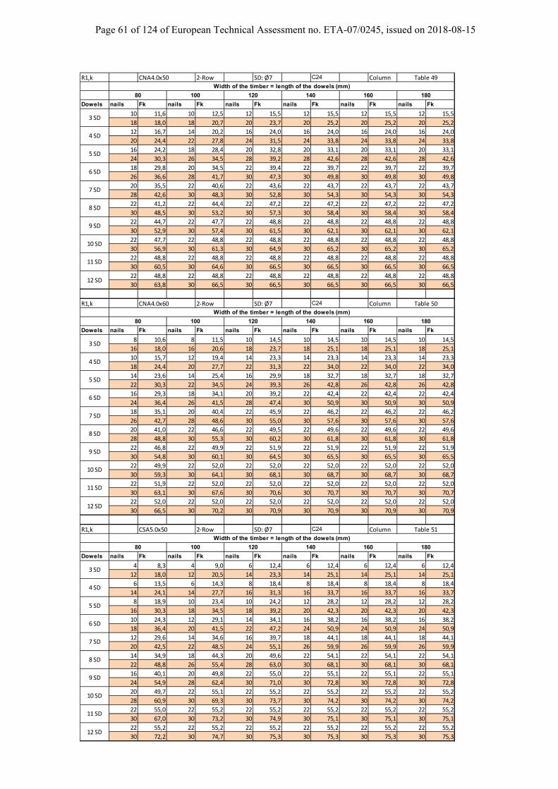
Page 61 of 124 of European Technical Assessment no. ETA-07/0245, issued on 2018-08-15
R1,k CNA4.0x50 2‐Row SD: Ø7 C24 Column
Dowels nails Fk nails Fk nails Fk nails Fk nails Fk nails Fk
10 11,6 10 12,5 12 15,5 12 15,5 12 15,5 12 15,5
18 18,0 18 20,7 20 23,7 20 25,2 20 25,2 20 25,2
12 16,7 14 20,2 16 24,0 16 24,0 16 24,0 16 24,0
20 24,4 22 27,8 24 31,5 24 33,8 24 33,8 24 33,8
16 24,2 18 28,4 20 32,8 20 33,1 20 33,1 20 33,1
24 30,3 26 34,5 28 39,2 28 42,6 28 42,6 28 42,6
18 29,8 20 34,5 22 39,4 22 39,7 22 39,7 22 39,7
26 36,6 28 41,7 30 47,3 30 49,8 30 49,8 30 49,8
20 35,5 22 40,6 22 43,6 22 43,7 22 43,7 22 43,7
28 42,6 30 48,3 30 52,8 30 54,3 30 54,3 30 54,3
22 41,2 22 44,4 22 47,2 22 47,2 22 47,2 22 47,2
30 48,5 30 53,2 30 57,3 30 58,4 30 58,4 30 58,4
22 44,7 22 47,7 22 48,8 22 48,8 22 48,8 22 48,8
30 52,9 30 57,4 30 61,5 30 62,1 30 62,1 30 62,1
22 47,7 22 48,8 22 48,8 22 48,8 22 48,8 22 48,8
30 56,9 30 61,3 30 64,9 30 65,2 30 65,2 30 65,2
22 48,8 22 48,8 22 48,8 22 48,8 22 48,8 22 48,8
30 60,5 30 64,6 30 66,5 30 66,5 30 66,5 30 66,5
22 48,8 22 48,8 22 48,8 22 48,8 22 48,8 22 48,8
30 63,8 30 66,5 30 66,5 30 66,5 30 66,5 30 66,5
R1,k CNA4.0x60 2‐Row SD: Ø7 C24 Column
Dowels nails Fk nails Fk nails Fk nails Fk nails Fk nails Fk
8 10,6 8 11,5 10 14,5 10 14,5 10 14,5 10 14,5
16 18,0 16 20,6 18 23,7 18 25,1 18 25,1 18 25,1
10 15,7 12 19,4 14 23,3 14 23,3 14 23,3 14 23,3
18 24,4 20 27,7 22 31,3 22 34,0 22 34,0 22 34,0
14 23,6 14 25,4 16 29,9 18 32,7 18 32,7 18 32,7
22 30,3 22 34,5 24 39,3 26 42,8 26 42,8 26 42,8
16 29,3 18 34,1 20 39,2 22 42,4 22 42,4 22 42,4
24 36,4 26 41,5 28 47,4 30 50,9 30 50,9 30 50,9
18 35,1 20 40,4 22 45,9 22 46,2 22 46,2 22 46,2
26 42,7 28 48,6 30 55,0 30 57,6 30 57,6 30 57,6
20 41,0 22 46,6 22 49,5 22 49,6 22 49,6 22 49,6
28 48,8 30 55,3 30 60,2 30 61,8 30 61,8 30 61,8
22 46,8 22 49,9 22 51,9 22 51,9 22 51,9 22 51,9
30 54,8 30 60,1 30 64,5 30 65,5 30 65,5 30 65,5
22 49,9 22 52,0 22 52,0 22 52,0 22 52,0 22 52,0
30 59,3 30 64,1 30 68,1 30 68,7 30 68,7 30 68,7
22 51,9 22 52,0 22 52,0 22 52,0 22 52,0 22 52,0
30 63,1 30 67,6 30 70,6 30 70,7 30 70,7 30 70,7
22 52,0 22 52,0 22 52,0 22 52,0 22 52,0 22 52,0
30 66,5 30 70,2 30 70,9 30 70,9 30 70,9 30 70,9
R1,k CSA5.0x50 2‐Row SD: Ø7 C24 Column
Dowels nails Fk nails Fk nails Fk nails Fk nails Fk nails Fk
4 8,3 4 9,0 6 12,4 6 12,4 6 12,4 6 12,4
12 18,0 12 20,5 14 23,3 14 25,1 14 25,1 14 25,1
6 13,5 6 14,3 8 18,4 8 18,4 8 18,4 8 18,4
14 24,1 14 27,7 16 31,3 16 33,7 16 33,7 16 33,7
8 18,9 10 23,4 10 24,2 12 28,2 12 28,2 12 28,2
16 30,3 18 34,5 18 39,2 20 42,3 20 42,3 20 42,3
10 24,3 12 29,1 14 34,1 16 38,2 16 38,2 16 38,2
18 36,4 20 41,5 22 47,2 24 50,9 24 50,9 24 50,9
12 29,6 14 34,6 16 39,7 18 44,1 18 44,1 18 44,1
20 42,5 22 48,5 24 55,1 26 59,9 26 59,9 26 59,9
14 34,9 18 44,3 20 49,6 22 54,1 22 54,1 22 54,1
22 48,8 26 55,4 28 63,0 30 68,1 30 68,1 30 68,1
16 40,1 20 49,8 22 55,0 22 55,1 22 55,1 22 55,1
24 54,9 28 62,4 30 71,0 30 72,8 30 72,8 30 72,8
20 49,7 22 55,1 22 55,2 22 55,2 22 55,2 22 55,2
28 60,9 30 69,3 30 73,7 30 74,2 30 74,2 30 74,2
22 55,0 22 55,2 22 55,2 22 55,2 22 55,2 22 55,2
30 67,0 30 73,2 30 74,9 30 75,1 30 75,1 30 75,1
22 55,2 22 55,2 22 55,2 22 55,2 22 55,2 22 55,2
30 72,2 30 74,7 30 75,3 30 75,3 30 75,3 30 75,3
Table 49Width of the timber = length of the dowels (mm)
180
3 SD
80 100
4 SD
5 SD
6 SD
120 140 160
10 SD
11 SD
12 SD
7 SD
8 SD
9 SD
80 100 120 140 160 180
Table 50
Width of the timber = length of the dowels (mm)
6 SD
7 SD
8 SD
3 SD
4 SD
5 SD
12 SD
Table 51
Width of the timber = length of the dowels (mm)
9 SD
10 SD
11 SD
80 100 120 140 160 180
7 SD
8 SD
3 SD
4 SD
5 SD
12 SD
9 SD
10 SD
11 SD
6 SD

Page 62 of 124 of European Technical Assessment no. ETA-07/0245, issued on 2018-08-15
R1,k CNA4.0x50 4‐Row SD: Ø7 CLT Column
Dowels nails Fk nails Fk nails Fk nails Fk nails Fk nails Fk
8 7,0 8 7,7 12 10,8 12 11,3 12 11,3 12 11,3
24 18,0 24 20,5 28 23,3 28 25,7 28 25,7 28 25,7
12 12,2 16 16,3 16 17,5 16 18,3 16 18,3 16 18,3
28 24,1 32 27,5 32 31,4 32 33,8 32 33,8 32 33,8
16 18,4 16 19,9 20 25,0 20 26,1 20 26,1 20 26,1
32 30,3 32 34,5 36 39,5 36 42,3 36 42,3 36 42,3
20 25,2 20 27,2 24 33,1 28 38,7 28 38,7 28 38,7
36 36,4 36 41,5 40 47,4 44 50,9 44 50,9 44 50,9
24 32,4 24 34,9 28 41,6 32 47,7 32 47,7 32 47,7
40 42,5 40 48,6 44 55,3 48 59,5 48 59,5 48 59,5
24 36,2 28 42,9 32 50,3 36 56,9 36 56,9 36 56,9
40 48,8 44 55,6 48 63,1 52 68,1 52 68,1 52 68,1
28 43,7 32 51,1 36 59,2 36 61,9 36 61,9 36 61,9
44 54,9 48 62,4 52 70,9 52 76,7 52 76,7 52 76,7
32 51,3 36 59,3 40 68,1 40 71,2 40 71,2 40 71,2
48 60,9 52 69,3 56 78,8 56 85,3 56 85,3 56 85,3
32 55,4 36 63,8 44 77,0 44 80,6 44 80,6 44 80,6
48 67,0 52 76,3 60 86,8 60 94,0 60 94,0 60 94,0
36 63,0 40 72,1 44 81,9 44 85,6 44 85,6 44 85,6
52 73,3 56 83,4 60 94,7 60 100,9 60 100,9 60 100,9
R1,k CNA4.0x60 4‐Row SD: Ø7 CLT Column
Dowels nails Fk nails Fk nails Fk nails Fk nails Fk nails Fk
8 7,5 8 8,1 8 8,9 12 12,3 12 12,3 12 12,3
24 18,0 24 20,5 24 23,7 28 25,1 28 25,1 28 25,1
8 10,6 12 14,2 12 15,4 16 19,8 16 19,8 16 19,8
24 24,3 28 27,5 28 31,5 32 33,7 32 33,7 32 33,7
12 16,4 16 21,3 16 23,0 20 28,2 20 28,2 20 28,2
28 30,5 32 34,5 32 39,5 36 42,3 36 42,3 36 42,3
16 23,3 20 29,1 20 31,3 24 37,2 24 37,2 24 37,2
32 36,4 36 41,5 36 47,4 40 50,9 40 50,9 40 50,9
20 30,7 20 33,2 24 40,1 24 41,9 24 41,9 24 41,9
36 42,5 36 48,6 40 55,1 40 59,5 40 59,5 40 59,5
20 34,5 24 41,5 28 49,1 28 51,3 28 51,3 28 51,3
36 48,8 40 55,5 44 63,0 44 68,2 44 68,2 44 68,2
24 42,3 28 49,9 32 58,3 32 60,9 32 60,9 32 60,9
40 54,8 44 62,4 48 70,9 48 76,9 48 76,9 48 76,9
28 50,2 28 54,2 32 62,9 36 70,5 36 70,5 36 70,5
44 60,9 44 69,3 48 78,8 52 85,5 52 85,5 52 85,5
28 54,2 32 62,8 36 72,2 40 80,1 40 80,1 40 80,1
44 67,1 48 76,4 52 86,9 56 94,0 56 94,0 56 94,0
32 62,1 36 71,4 40 81,4 44 89,8 44 89,8 44 89,8
48 73,1 52 83,2 56 94,8 60 102,4 60 102,4 60 102,4
R1,k CSA5.0x50 4‐Row SD: Ø7 CLT Column
Dowels nails Fk nails Fk nails Fk nails Fk nails Fk nails Fk
8 10,5 8 11,1 8 11,8 8 12,2 8 12,2 8 12,2
16 18,0 16 20,5 16 23,7 20 25,1 20 25,1 20 25,1
8 13,0 8 13,9 8 14,9 8 15,5 8 15,5 8 15,5
16 24,2 20 27,5 20 31,3 20 34,1 20 34,1 20 34,1
8 15,7 8 17,8 8 19,8 8 19,8 8 19,8 8 19,8
20 30,3 20 34,5 24 39,2 24 42,3 24 42,3 24 42,3
8 20,1 8 20,1 12 26,9 12 27,8 12 27,8 12 27,8
24 36,4 24 41,5 28 47,2 28 50,9 28 50,9 28 50,9
8 20,1 12 30,1 12 30,1 16 37,4 16 37,4 16 37,4
24 42,5 28 48,4 28 55,3 32 59,5 32 59,5 32 59,5
12 30,1 12 30,1 16 40,2 20 47,2 20 47,2 20 47,2
28 48,7 28 55,5 32 63,0 36 68,1 36 68,1 36 68,1
12 30,1 16 40,2 20 50,2 20 50,2 20 50,2 20 50,2
28 54,9 32 62,4 36 70,9 36 77,0 36 77,0 36 77,0
16 40,2 20 50,2 24 59,1 24 59,4 24 59,4 24 59,4
32 60,9 36 69,3 40 78,8 40 85,3 40 85,3 40 85,3
16 40,2 20 50,2 24 60,2 28 69,3 28 69,3 28 69,3
32 67,0 36 76,4 40 86,9 44 93,9 44 93,9 44 93,9
20 50,2 24 60,2 28 70,3 32 79,3 32 79,3 32 79,3
36 73,1 40 83,2 44 94,7 48 102,4 48 102,4 48 102,4
3 SD
4 SD
5 SD
6 SD
7 SD
8 SD
Table 52Width of the timber = length of the dowels (mm)
80 100 120 140 160 180
140 160 180
9 SD
10 SD
11 SD
12 SD
Table 53Width of the timber = length of the dowels (mm)
3 SD
4 SD
5 SD
6 SD
7 SD
8 SD
80 100 120
80 100 120 140 160 180
9 SD
10 SD
11 SD
12 SD
Table 54Width of the timber = length of the dowels (mm)
9 SD
10 SD
11 SD
12 SD
3 SD
4 SD
5 SD
6 SD
7 SD
8 SD

Page 63 of 124 of European Technical Assessment no. ETA-07/0245, issued on 2018-08-15
R1,k CNA4.0x50 4‐Row SD: Ø8 C24 Header
Dowels nails Fk nails Fk nails Fk nails Fk nails Fk nails Fk
20 12,3 20 13,4 20 14,4 24 16,8 24 16,8 24 16,8
32 18,3 36 20,5 36 23,5 40 25,1 40 25,1 40 25,1
20 15,9 24 19,6 28 23,8 28 23,8 28 23,8 28 23,8
36 24,1 40 27,8 44 31,5 44 34,1 44 34,1 44 34,1
28 24,1 28 26,5 32 31,4 36 34,4 36 34,4 36 34,4
44 30,3 44 34,6 48 39,5 52 42,5 52 42,5 52 42,5
32 30,5 36 35,9 36 39,4 40 42,6 40 42,6 40 42,6
48 36,5 52 41,5 52 47,2 56 51,3 56 51,3 56 51,3
36 37,2 40 43,2 44 49,9 44 51,2 44 51,2 44 51,2
52 42,6 56 48,5 60 55,2 60 59,8 60 59,8 60 59,8
40 43,9 44 50,7 48 58,1 48 59,9 48 59,9 48 59,9
56 48,7 60 55,5 64 63,2 64 68,2 64 68,2 64 68,2
40 48,8 48 58,1 52 66,4 56 71,3 56 71,3 56 71,3
56 54,8 64 62,4 68 71,1 72 76,9 72 76,9 72 76,9
44 55,6 52 65,6 56 74,7 60 80,1 60 80,1 60 80,1
60 61,0 68 69,4 72 79,0 76 85,5 76 85,5 76 85,5
48 62,4 52 71,4 60 83,0 64 88,9 64 88,9 64 88,9
64 67,1 68 76,3 76 86,9 80 94,1 80 94,1 80 94,1
52 69,2 56 78,9 64 91,3 68 97,8 68 97,8 68 97,8
68 73,3 72 83,3 80 94,8 84 102,6 84 102,6 84 102,6
R1,k CNA4.0x60 4‐Row SD: Ø8 C24 Header
Dowels nails Fk nails Fk nails Fk nails Fk nails Fk nails Fk
20 13,6 20 14,7 20 15,7 20 15,7 20 15,7 20 15,7
28 18,1 32 20,5 32 23,5 36 25,1 36 25,1 36 25,1
20 17,1 20 18,7 24 23,0 24 23,0 24 23,0 24 23,0
32 24,1 36 27,8 40 31,3 40 34,2 40 34,2 40 34,2
24 23,4 24 25,8 28 30,9 28 31,1 28 31,1 28 31,1
40 30,3 40 34,7 44 39,5 44 42,4 44 42,4 44 42,4
24 27,7 28 33,2 32 39,2 36 42,7 36 42,7 36 42,7
40 36,4 44 41,6 48 47,4 52 50,9 52 50,9 52 50,9
28 34,6 32 40,8 36 47,6 40 51,5 40 51,5 40 51,5
44 42,6 48 48,6 52 55,3 56 59,8 56 59,8 56 59,8
32 41,7 36 48,6 40 56,2 44 60,5 44 60,5 44 60,5
48 48,8 52 55,5 56 63,2 60 68,4 60 68,4 60 68,4
36 48,7 40 56,4 44 64,8 48 69,5 48 69,5 48 69,5
52 54,9 56 62,5 60 71,1 64 77,0 64 77,0 64 77,0
40 55,8 44 64,1 48 73,3 52 78,7 52 78,7 52 78,7
56 61,0 60 69,5 64 79,0 68 85,5 68 85,5 68 85,5
44 62,7 48 71,8 52 81,9 56 87,8 56 87,8 56 87,8
60 67,1 64 76,4 68 86,9 72 94,1 72 94,1 72 94,1
44 67,9 52 79,5 56 90,4 60 96,9 60 96,9 60 96,9
60 73,2 68 83,3 72 94,8 76 102,6 76 102,6 76 102,6
R1,k CSA5.0x50 4‐Row SD: Ø8 C24 Header
Dowels nails Fk nails Fk nails Fk nails Fk nails Fk nails Fk
20 18,0 20 20,8 20 23,0 20 23,7 20 23,7 20 23,7
20 18,0 20 20,8 24 23,3 24 25,1 24 25,1 24 25,1
20 23,5 20 25,5 20 27,4 20 27,8 20 27,8 20 27,8
24 24,1 24 27,6 28 31,3 28 33,7 28 33,7 28 33,7
20 27,3 20 29,6 20 32,1 20 32,3 20 32,3 20 32,3
24 30,4 28 34,5 28 39,3 32 42,3 32 42,3 32 42,3
20 31,2 20 34,0 20 37,0 20 37,1 20 37,1 20 37,1
28 36,6 32 41,5 32 47,4 36 50,9 36 50,9 36 50,9
20 35,2 20 38,6 20 42,1 20 42,1 20 42,1 20 42,1
32 42,5 32 48,5 36 55,2 36 59,5 36 59,5 36 59,5
20 39,4 20 43,3 24 51,4 24 51,8 24 51,8 24 51,8
32 48,7 36 55,5 40 63,0 40 68,4 40 68,4 40 68,4
20 43,7 24 51,9 28 60,8 28 61,6 28 61,6 28 61,6
36 54,9 40 62,4 44 70,9 44 77,0 44 77,0 44 77,0
24 51,7 24 56,4 28 65,7 32 71,4 32 71,4 32 71,4
40 60,9 40 69,4 44 79,0 48 85,3 48 85,3 48 85,3
24 55,9 28 65,2 32 75,1 36 81,3 36 81,3 36 81,3
40 67,2 44 76,4 48 86,9 52 93,9 52 93,9 52 93,9
28 63,9 32 73,8 36 84,4 36 86,0 36 86,0 36 86,0
44 73,1 48 83,2 52 94,7 52 102,4 52 102,4 52 102,4
Width of the timber = length of the dowels (mm)
80 100 120 140 160 180
Table 55
3 SD
4 SD
5 SD
6 SD
7 SD
8 SD
9 SD
10 SD
Width of the timber = length of the dowels (mm)
11 SD
12 SD
80 100 120 140 160 180
Table 56
3 SD
4 SD
5 SD
6 SD
7 SD
8 SD
9 SD
10 SD
Width of the timber = length of the dowels (mm)
11 SD
12 SD
80 100 120 140 160 180
Table 57
3 SD
4 SD
5 SD
6 SD
7 SD
8 SD
9 SD
10 SD
11 SD
12 SD
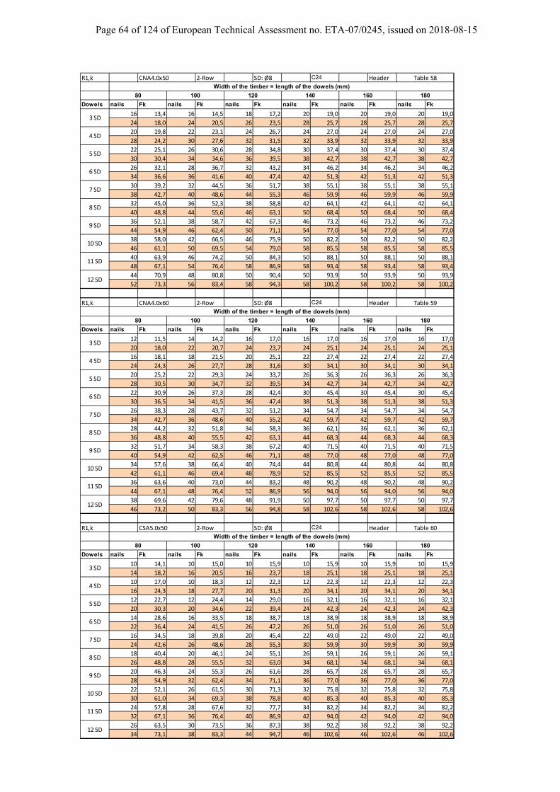
Page 64 of 124 of European Technical Assessment no. ETA-07/0245, issued on 2018-08-15
R1,k CNA4.0x50 2‐Row SD: Ø8 C24 Header
Dowels nails Fk nails Fk nails Fk nails Fk nails Fk nails Fk
16 13,4 16 14,5 18 17,2 20 19,0 20 19,0 20 19,0
24 18,0 24 20,5 26 23,5 28 25,7 28 25,7 28 25,7
20 19,8 22 23,1 24 26,7 24 27,0 24 27,0 24 27,0
28 24,2 30 27,6 32 31,5 32 33,9 32 33,9 32 33,9
22 25,1 26 30,6 28 34,8 30 37,4 30 37,4 30 37,4
30 30,4 34 34,6 36 39,5 38 42,7 38 42,7 38 42,7
26 32,1 28 36,7 32 43,2 34 46,2 34 46,2 34 46,2
34 36,6 36 41,6 40 47,4 42 51,3 42 51,3 42 51,3
30 39,2 32 44,5 36 51,7 38 55,1 38 55,1 38 55,1
38 42,7 40 48,6 44 55,3 46 59,9 46 59,9 46 59,9
32 45,0 36 52,3 38 58,8 42 64,1 42 64,1 42 64,1
40 48,8 44 55,6 46 63,1 50 68,4 50 68,4 50 68,4
36 52,1 38 58,7 42 67,3 46 73,2 46 73,2 46 73,2
44 54,9 46 62,4 50 71,1 54 77,0 54 77,0 54 77,0
38 58,0 42 66,5 46 75,9 50 82,2 50 82,2 50 82,2
46 61,1 50 69,5 54 79,0 58 85,5 58 85,5 58 85,5
40 63,9 46 74,2 50 84,3 50 88,1 50 88,1 50 88,1
48 67,1 54 76,4 58 86,9 58 93,4 58 93,4 58 93,4
44 70,9 48 80,8 50 90,4 50 93,9 50 93,9 50 93,9
52 73,3 56 83,4 58 94,3 58 100,2 58 100,2 58 100,2
R1,k CNA4.0x60 2‐Row SD: Ø8 C24 Header
Dowels nails Fk nails Fk nails Fk nails Fk nails Fk nails Fk
12 11,5 14 14,2 16 17,0 16 17,0 16 17,0 16 17,0
20 18,0 22 20,7 24 23,7 24 25,1 24 25,1 24 25,1
16 18,1 18 21,5 20 25,1 22 27,4 22 27,4 22 27,4
24 24,3 26 27,7 28 31,6 30 34,1 30 34,1 30 34,1
20 25,2 22 29,3 24 33,7 26 36,3 26 36,3 26 36,3
28 30,5 30 34,7 32 39,5 34 42,7 34 42,7 34 42,7
22 30,9 26 37,3 28 42,4 30 45,4 30 45,4 30 45,4
30 36,5 34 41,5 36 47,4 38 51,3 38 51,3 38 51,3
26 38,3 28 43,7 32 51,2 34 54,7 34 54,7 34 54,7
34 42,7 36 48,6 40 55,2 42 59,7 42 59,7 42 59,7
28 44,2 32 51,8 34 58,3 36 62,1 36 62,1 36 62,1
36 48,8 40 55,5 42 63,1 44 68,3 44 68,3 44 68,3
32 51,7 34 58,3 38 67,2 40 71,5 40 71,5 40 71,5
40 54,9 42 62,5 46 71,1 48 77,0 48 77,0 48 77,0
34 57,6 38 66,4 40 74,4 44 80,8 44 80,8 44 80,8
42 61,1 46 69,4 48 78,9 52 85,5 52 85,5 52 85,5
36 63,6 40 73,0 44 83,2 48 90,2 48 90,2 48 90,2
44 67,1 48 76,4 52 86,9 56 94,0 56 94,0 56 94,0
38 69,6 42 79,6 48 91,9 50 97,7 50 97,7 50 97,7
46 73,2 50 83,3 56 94,8 58 102,6 58 102,6 58 102,6
R1,k CSA5.0x50 2‐Row SD: Ø8 C24 Header
Dowels nails Fk nails Fk nails Fk nails Fk nails Fk nails Fk
10 14,1 10 15,0 10 15,9 10 15,9 10 15,9 10 15,9
14 18,2 16 20,5 16 23,7 18 25,1 18 25,1 18 25,1
10 17,0 10 18,3 12 22,3 12 22,3 12 22,3 12 22,3
16 24,3 18 27,7 20 31,3 20 34,1 20 34,1 20 34,1
12 22,7 12 24,4 14 29,0 16 32,1 16 32,1 16 32,1
20 30,3 20 34,6 22 39,4 24 42,3 24 42,3 24 42,3
14 28,6 16 33,5 18 38,7 18 38,9 18 38,9 18 38,9
22 36,4 24 41,5 26 47,2 26 51,0 26 51,0 26 51,0
16 34,5 18 39,8 20 45,4 22 49,0 22 49,0 22 49,0
24 42,6 26 48,6 28 55,3 30 59,9 30 59,9 30 59,9
18 40,4 20 46,1 24 55,1 26 59,1 26 59,1 26 59,1
26 48,8 28 55,5 32 63,0 34 68,1 34 68,1 34 68,1
20 46,3 24 55,3 26 61,6 28 65,7 28 65,7 28 65,7
28 54,9 32 62,4 34 71,1 36 77,0 36 77,0 36 77,0
22 52,1 26 61,5 30 71,3 32 75,8 32 75,8 32 75,8
30 61,0 34 69,3 38 78,8 40 85,3 40 85,3 40 85,3
24 57,8 28 67,6 32 77,7 34 82,2 34 82,2 34 82,2
32 67,1 36 76,4 40 86,9 42 94,0 42 94,0 42 94,0
26 63,5 30 73,5 36 87,3 38 92,2 38 92,2 38 92,2
34 73,1 38 83,3 44 94,7 46 102,6 46 102,6 46 102,6
Width of the timber = length of the dowels (mm)
Table 58
80 100 120 140 160 180
3 SD
4 SD
5 SD
6 SD
7 SD
8 SD
9 SD
10 SD
Width of the timber = length of the dowels (mm)
11 SD
12 SD
Table 59
80 100 120 140 160 180
3 SD
4 SD
5 SD
6 SD
7 SD
8 SD
9 SD
10 SD
Width of the timber = length of the dowels (mm)
11 SD
12 SD
Table 60
80 100 120 140 160 180
3 SD
4 SD
5 SD
6 SD
7 SD
8 SD
9 SD
10 SD
11 SD
12 SD
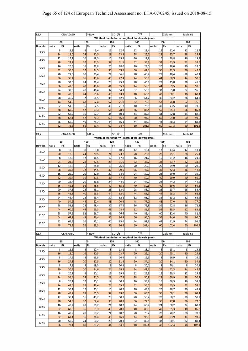
Page 65 of 124 of European Technical Assessment no. ETA-07/0245, issued on 2018-08-15
R1,k CNA4.0x50 4‐Row SD: Ø8 C24 Column
Dowels nails Fk nails Fk nails Fk nails Fk nails Fk nails Fk
8 8,3 8 9,4 12 12,4 12 12,4 12 12,4 12 12,4
24 18,0 24 20,5 28 23,3 28 25,7 28 25,7 28 25,7
12 14,1 16 18,3 16 19,8 16 19,8 16 19,8 16 19,8
28 24,2 32 27,5 32 31,5 32 33,9 32 33,9 32 33,9
16 20,6 16 22,8 20 28,0 20 28,0 20 28,0 20 28,0
32 30,3 32 34,5 36 39,5 36 42,3 36 42,3 36 42,3
20 27,6 20 30,4 24 36,6 28 40,4 28 40,4 28 40,4
36 36,4 36 41,6 40 47,4 44 50,9 44 50,9 44 50,9
20 32,0 24 38,4 28 45,3 28 45,8 28 45,8 28 45,8
36 42,5 40 48,6 44 55,3 44 59,5 44 59,5 44 59,5
24 39,3 28 46,4 32 54,1 32 55,0 32 55,0 32 55,0
40 48,8 44 55,6 48 63,1 48 68,1 48 68,1 48 68,1
28 46,7 32 54,5 36 62,9 36 64,2 36 64,2 36 64,2
44 54,9 48 62,4 52 71,0 52 76,8 52 76,8 52 76,8
32 54,0 36 62,5 40 71,7 40 73,5 40 73,5 40 73,5
48 60,9 52 69,3 56 78,8 56 85,4 56 85,4 56 85,4
32 58,7 36 67,7 44 80,4 44 82,8 44 82,8 44 82,8
48 67,1 52 76,3 60 86,8 60 94,0 60 94,0 60 94,0
36 66,0 40 75,7 44 86,1 44 88,3 44 88,3 44 88,3
52 73,3 56 83,4 60 94,7 60 101,3 60 101,3 60 101,3
R1,k CNA4.0x60 4‐Row SD: Ø8 C24 Column
Dowels nails Fk nails Fk nails Fk nails Fk nails Fk nails Fk
8 8,8 8 9,8 8 10,5 12 13,4 12 13,4 12 13,4
20 18,0 24 20,5 24 23,7 28 25,1 28 25,1 28 25,1
8 12,3 12 16,5 12 17,8 16 21,2 16 21,2 16 21,2
24 24,3 28 27,5 28 31,6 32 33,7 32 33,7 32 33,7
12 18,8 16 24,0 16 26,0 20 29,9 20 29,9 20 29,9
28 30,5 32 34,5 32 39,5 36 42,3 36 42,3 36 42,3
16 25,9 20 32,0 20 34,9 24 39,0 24 39,0 24 39,0
32 36,4 36 41,5 36 47,4 40 50,9 40 50,9 40 50,9
20 33,4 20 36,8 24 44,0 24 44,2 24 44,2 24 44,2
36 42,5 36 48,6 40 55,2 40 59,6 40 59,6 40 59,6
20 37,8 24 45,1 28 53,0 28 53,7 28 53,7 28 53,7
36 48,8 40 55,5 44 63,0 44 68,3 44 68,3 44 68,3
24 45,4 28 53,4 32 62,1 32 63,2 32 63,2 32 63,2
40 54,9 44 62,4 48 70,9 48 77,0 48 77,0 48 77,0
28 53,1 28 58,4 32 67,5 36 72,8 36 72,8 36 72,8
44 60,9 44 69,3 48 78,9 52 85,5 52 85,5 52 85,5
28 57,6 32 66,7 36 76,6 40 82,4 40 82,4 40 82,4
44 67,1 48 76,4 52 86,9 56 94,0 56 94,0 56 94,0
32 65,3 36 75,1 40 85,6 44 91,9 44 91,9 44 91,9
48 73,2 52 83,3 56 94,8 60 102,4 60 102,4 60 102,4
R1,k CSA5.0x50 4‐Row SD: Ø8 C24 Column
Dowels nails Fk nails Fk nails Fk nails Fk nails Fk nails Fk
8 11,5 8 12,4 8 13,1 8 13,1 8 13,1 8 13,1
16 18,0 16 20,5 16 23,7 20 25,1 20 25,1 20 25,1
8 14,5 8 15,8 8 16,9 8 16,9 8 16,9 8 16,9
16 24,3 20 27,5 20 31,3 20 34,1 20 34,1 20 34,1
8 17,8 8 19,3 8 20,1 8 20,1 8 20,1 8 20,1
20 30,3 20 34,6 24 39,2 24 42,3 24 42,3 24 42,3
8 20,1 8 20,1 12 29,3 12 29,3 12 29,3 12 29,3
24 36,4 24 41,5 28 47,2 28 50,9 28 50,9 28 50,9
8 20,1 12 30,1 12 30,1 16 38,9 16 38,9 16 38,9
24 42,6 28 48,4 28 55,3 32 59,5 32 59,5 32 59,5
12 30,1 12 30,1 16 40,2 20 48,7 20 48,7 20 48,7
28 48,7 28 55,5 32 63,0 36 68,1 36 68,1 36 68,1
12 30,1 16 40,2 20 50,2 20 50,2 20 50,2 20 50,2
28 54,9 32 62,4 36 70,9 36 77,0 36 77,0 36 77,0
16 40,2 20 50,2 24 60,2 24 60,2 24 60,2 24 60,2
32 60,9 36 69,3 40 78,8 40 85,3 40 85,3 40 85,3
16 40,2 20 50,2 24 60,2 28 70,2 28 70,2 28 70,2
32 67,1 36 76,4 40 86,9 44 93,9 44 93,9 44 93,9
20 50,2 24 60,2 28 70,3 32 80,1 32 80,1 32 80,1
36 73,1 40 83,2 44 94,7 48 102,4 48 102,4 48 102,4
Width of the timber = length of the dowels (mm)
Table 61
80 100 120 140 160 180
3 SD
4 SD
5 SD
6 SD
7 SD
8 SD
9 SD
10 SD
Width of the timber = length of the dowels (mm)
11 SD
12 SD
Table 62
80 100 120 140 160 180
3 SD
4 SD
5 SD
6 SD
7 SD
8 SD
9 SD
10 SD
Width of the timber = length of the dowels (mm)
11 SD
12 SD
Table 63
80 100 120 140 160 180
3 SD
4 SD
5 SD
6 SD
7 SD
8 SD
9 SD
10 SD
11 SD
12 SD
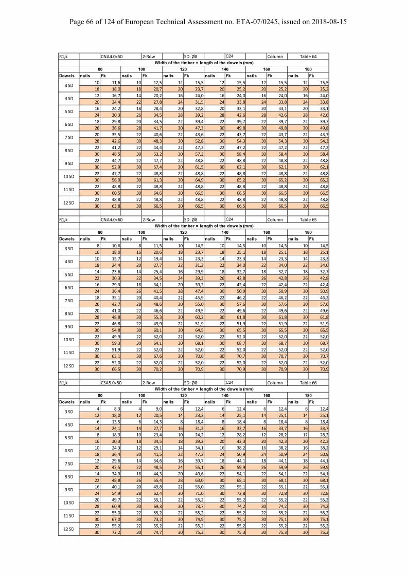
Page 66 of 124 of European Technical Assessment no. ETA-07/0245, issued on 2018-08-15
R1,k CNA4.0x50 2‐Row SD: Ø8 C24 Column
Dowels nails Fk nails Fk nails Fk nails Fk nails Fk nails Fk
10 11,6 10 12,5 12 15,5 12 15,5 12 15,5 12 15,5
18 18,0 18 20,7 20 23,7 20 25,2 20 25,2 20 25,2
12 16,7 14 20,2 16 24,0 16 24,0 16 24,0 16 24,0
20 24,4 22 27,8 24 31,5 24 33,8 24 33,8 24 33,8
16 24,2 18 28,4 20 32,8 20 33,1 20 33,1 20 33,1
24 30,3 26 34,5 28 39,2 28 42,6 28 42,6 28 42,6
18 29,8 20 34,5 22 39,4 22 39,7 22 39,7 22 39,7
26 36,6 28 41,7 30 47,3 30 49,8 30 49,8 30 49,8
20 35,5 22 40,6 22 43,6 22 43,7 22 43,7 22 43,7
28 42,6 30 48,3 30 52,8 30 54,3 30 54,3 30 54,3
22 41,2 22 44,4 22 47,2 22 47,2 22 47,2 22 47,2
30 48,5 30 53,2 30 57,3 30 58,4 30 58,4 30 58,4
22 44,7 22 47,7 22 48,8 22 48,8 22 48,8 22 48,8
30 52,9 30 57,4 30 61,5 30 62,1 30 62,1 30 62,1
22 47,7 22 48,8 22 48,8 22 48,8 22 48,8 22 48,8
30 56,9 30 61,3 30 64,9 30 65,2 30 65,2 30 65,2
22 48,8 22 48,8 22 48,8 22 48,8 22 48,8 22 48,8
30 60,5 30 64,6 30 66,5 30 66,5 30 66,5 30 66,5
22 48,8 22 48,8 22 48,8 22 48,8 22 48,8 22 48,8
30 63,8 30 66,5 30 66,5 30 66,5 30 66,5 30 66,5
R1,k CNA4.0x60 2‐Row SD: Ø8 C24 Column
Dowels nails Fk nails Fk nails Fk nails Fk nails Fk nails Fk
8 10,6 8 11,5 10 14,5 10 14,5 10 14,5 10 14,5
16 18,0 16 20,6 18 23,7 18 25,1 18 25,1 18 25,1
10 15,7 12 19,4 14 23,3 14 23,3 14 23,3 14 23,3
18 24,4 20 27,7 22 31,3 22 34,0 22 34,0 22 34,0
14 23,6 14 25,4 16 29,9 18 32,7 18 32,7 18 32,7
22 30,3 22 34,5 24 39,3 26 42,8 26 42,8 26 42,8
16 29,3 18 34,1 20 39,2 22 42,4 22 42,4 22 42,4
24 36,4 26 41,5 28 47,4 30 50,9 30 50,9 30 50,9
18 35,1 20 40,4 22 45,9 22 46,2 22 46,2 22 46,2
26 42,7 28 48,6 30 55,0 30 57,6 30 57,6 30 57,6
20 41,0 22 46,6 22 49,5 22 49,6 22 49,6 22 49,6
28 48,8 30 55,3 30 60,2 30 61,8 30 61,8 30 61,8
22 46,8 22 49,9 22 51,9 22 51,9 22 51,9 22 51,9
30 54,8 30 60,1 30 64,5 30 65,5 30 65,5 30 65,5
22 49,9 22 52,0 22 52,0 22 52,0 22 52,0 22 52,0
30 59,3 30 64,1 30 68,1 30 68,7 30 68,7 30 68,7
22 51,9 22 52,0 22 52,0 22 52,0 22 52,0 22 52,0
30 63,1 30 67,6 30 70,6 30 70,7 30 70,7 30 70,7
22 52,0 22 52,0 22 52,0 22 52,0 22 52,0 22 52,0
30 66,5 30 70,2 30 70,9 30 70,9 30 70,9 30 70,9
R1,k CSA5.0x50 2‐Row SD: Ø8 C24 Column
Dowels nails Fk nails Fk nails Fk nails Fk nails Fk nails Fk
4 8,3 4 9,0 6 12,4 6 12,4 6 12,4 6 12,4
12 18,0 12 20,5 14 23,3 14 25,1 14 25,1 14 25,1
6 13,5 6 14,3 8 18,4 8 18,4 8 18,4 8 18,4
14 24,1 14 27,7 16 31,3 16 33,7 16 33,7 16 33,7
8 18,9 10 23,4 10 24,2 12 28,2 12 28,2 12 28,2
16 30,3 18 34,5 18 39,2 20 42,3 20 42,3 20 42,3
10 24,3 12 29,1 14 34,1 16 38,2 16 38,2 16 38,2
18 36,4 20 41,5 22 47,2 24 50,9 24 50,9 24 50,9
12 29,6 14 34,6 16 39,7 18 44,1 18 44,1 18 44,1
20 42,5 22 48,5 24 55,1 26 59,9 26 59,9 26 59,9
14 34,9 18 44,3 20 49,6 22 54,1 22 54,1 22 54,1
22 48,8 26 55,4 28 63,0 30 68,1 30 68,1 30 68,1
16 40,1 20 49,8 22 55,0 22 55,1 22 55,1 22 55,1
24 54,9 28 62,4 30 71,0 30 72,8 30 72,8 30 72,8
20 49,7 22 55,1 22 55,2 22 55,2 22 55,2 22 55,2
28 60,9 30 69,3 30 73,7 30 74,2 30 74,2 30 74,2
22 55,0 22 55,2 22 55,2 22 55,2 22 55,2 22 55,2
30 67,0 30 73,2 30 74,9 30 75,1 30 75,1 30 75,1
22 55,2 22 55,2 22 55,2 22 55,2 22 55,2 22 55,2
30 72,2 30 74,7 30 75,3 30 75,3 30 75,3 30 75,3
Table 64Width of the timber = length of the dowels (mm)
80 100 120 140 160 180
3 SD
4 SD
5 SD
6 SD
7 SD
8 SD
9 SD
10 SD
Table 65Width of the timber = length of the dowels (mm)
11 SD
12 SD
80 100 120 140 160 180
3 SD
4 SD
5 SD
6 SD
7 SD
8 SD
9 SD
10 SD
Table 66
Width of the timber = length of the dowels (mm)
11 SD
12 SD
80 100 120 140 160 180
3 SD
4 SD
5 SD
6 SD
7 SD
8 SD
9 SD
10 SD
11 SD
12 SD
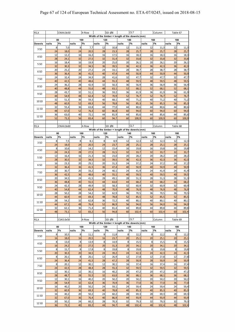
Page 67 of 124 of European Technical Assessment no. ETA-07/0245, issued on 2018-08-15
R1,k CNA4.0x50 4‐Row SD: Ø8 CLT Column
Dowels nails Fk nails Fk nails Fk nails Fk nails Fk nails Fk
8 7,0 8 7,7 12 10,8 12 11,3 12 11,3 12 11,3
24 18,0 24 20,5 28 23,3 28 25,7 28 25,7 28 25,7
12 12,2 16 16,3 16 17,5 16 18,3 16 18,3 16 18,3
28 24,1 32 27,5 32 31,4 32 33,8 32 33,8 32 33,8
16 18,4 16 19,9 20 25,0 20 26,1 20 26,1 20 26,1
32 30,3 32 34,5 36 39,5 36 42,3 36 42,3 36 42,3
20 25,2 20 27,2 24 33,1 28 38,7 28 38,7 28 38,7
36 36,4 36 41,5 40 47,4 44 50,9 44 50,9 44 50,9
24 32,4 24 34,9 28 41,6 32 47,7 32 47,7 32 47,7
40 42,5 40 48,6 44 55,3 48 59,5 48 59,5 48 59,5
24 36,2 28 42,9 32 50,3 36 56,9 36 56,9 36 56,9
40 48,8 44 55,6 48 63,1 52 68,1 52 68,1 52 68,1
28 43,7 32 51,1 36 59,2 36 61,9 36 61,9 36 61,9
44 54,9 48 62,4 52 70,9 52 76,7 52 76,7 52 76,7
32 51,3 36 59,3 40 68,1 40 71,2 40 71,2 40 71,2
48 60,9 52 69,3 56 78,8 56 85,3 56 85,3 56 85,3
32 55,4 36 63,8 44 77,0 44 80,6 44 80,6 44 80,6
48 67,0 52 76,3 60 86,8 60 94,0 60 94,0 60 94,0
36 63,0 40 72,1 44 81,9 44 85,6 44 85,6 44 85,6
52 73,3 56 83,4 60 94,7 60 100,9 60 100,9 60 100,9
R1,k CNA4.0x60 4‐Row SD: Ø8 CLT Column
Dowels nails Fk nails Fk nails Fk nails Fk nails Fk nails Fk
8 7,5 8 8,1 8 8,9 12 12,3 12 12,3 12 12,3
24 18,0 24 20,5 24 23,7 28 25,1 28 25,1 28 25,1
8 10,6 12 14,2 12 15,4 16 19,8 16 19,8 16 19,8
24 24,3 28 27,5 28 31,5 32 33,7 32 33,7 32 33,7
12 16,4 16 21,3 16 23,0 20 28,2 20 28,2 20 28,2
28 30,5 32 34,5 32 39,5 36 42,3 36 42,3 36 42,3
16 23,3 20 29,1 20 31,3 24 37,2 24 37,2 24 37,2
32 36,4 36 41,5 36 47,4 40 50,9 40 50,9 40 50,9
20 30,7 20 33,2 24 40,1 24 41,9 24 41,9 24 41,9
36 42,5 36 48,6 40 55,1 40 59,5 40 59,5 40 59,5
20 34,5 24 41,5 28 49,1 28 51,3 28 51,3 28 51,3
36 48,8 40 55,5 44 63,0 44 68,2 44 68,2 44 68,2
24 42,3 28 49,9 32 58,3 32 60,9 32 60,9 32 60,9
40 54,8 44 62,4 48 70,9 48 76,9 48 76,9 48 76,9
28 50,2 28 54,2 32 62,9 36 70,5 36 70,5 36 70,5
44 60,9 44 69,3 48 78,8 52 85,5 52 85,5 52 85,5
28 54,2 32 62,8 36 72,2 40 80,1 40 80,1 40 80,1
44 67,1 48 76,4 52 86,9 56 94,0 56 94,0 56 94,0
32 62,1 36 71,4 40 81,4 44 89,8 44 89,8 44 89,8
48 73,1 52 83,2 56 94,8 60 102,4 60 102,4 60 102,4
R1,k CSA5.0x50 4‐Row SD: Ø8 CLT Column
Dowels nails Fk nails Fk nails Fk nails Fk nails Fk nails Fk
8 10,5 8 11,1 8 11,8 8 12,2 8 12,2 8 12,2
16 18,0 16 20,5 16 23,7 20 25,1 20 25,1 20 25,1
8 13,0 8 13,9 8 14,9 8 15,5 8 15,5 8 15,5
16 24,2 20 27,5 20 31,3 20 34,1 20 34,1 20 34,1
8 15,7 8 17,8 8 19,8 8 19,8 8 19,8 8 19,8
20 30,3 20 34,5 24 39,2 24 42,3 24 42,3 24 42,3
8 20,1 8 20,1 12 26,9 12 27,8 12 27,8 12 27,8
24 36,4 24 41,5 28 47,2 28 50,9 28 50,9 28 50,9
8 20,1 12 30,1 12 30,1 16 37,4 16 37,4 16 37,4
24 42,5 28 48,4 28 55,3 32 59,5 32 59,5 32 59,5
12 30,1 12 30,1 16 40,2 20 47,2 20 47,2 20 47,2
28 48,7 28 55,5 32 63,0 36 68,1 36 68,1 36 68,1
12 30,1 16 40,2 20 50,2 20 50,2 20 50,2 20 50,2
28 54,9 32 62,4 36 70,9 36 77,0 36 77,0 36 77,0
16 40,2 20 50,2 24 59,1 24 59,4 24 59,4 24 59,4
32 60,9 36 69,3 40 78,8 40 85,3 40 85,3 40 85,3
16 40,2 20 50,2 24 60,2 28 69,3 28 69,3 28 69,3
32 67,0 36 76,4 40 86,9 44 93,9 44 93,9 44 93,9
20 50,2 24 60,2 28 70,3 32 79,3 32 79,3 32 79,3
36 73,1 40 83,2 44 94,7 48 102,4 48 102,4 48 102,4
Table 67
Width of the timber = length of the dowels (mm)
80 100 120 140 160 180
3 SD
4 SD
5 SD
6 SD
7 SD
8 SD
9 SD
10 SD
Table 68
Width of the timber = length of the dowels (mm)
11 SD
12 SD
80 100 120 140 160 180
3 SD
4 SD
5 SD
6 SD
7 SD
8 SD
9 SD
10 SD
Table 69
Width of the timber = length of the dowels (mm)
11 SD
12 SD
80 100 120 140 160 180
3 SD
4 SD
5 SD
6 SD
7 SD
8 SD
9 SD
10 SD
11 SD
12 SD
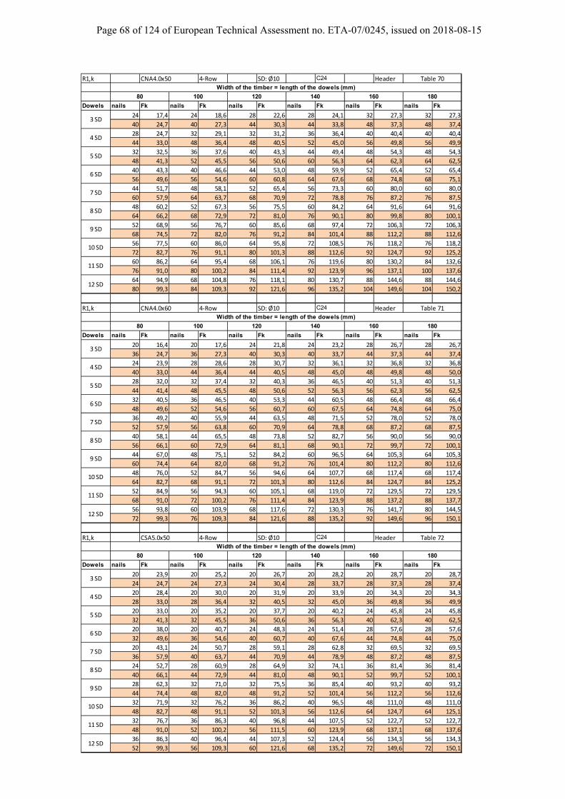
Page 68 of 124 of European Technical Assessment no. ETA-07/0245, issued on 2018-08-15
R1,k CNA4.0x50 4‐Row SD: Ø10 C24 Header
Dowels nails Fk nails Fk nails Fk nails Fk nails Fk nails Fk
24 17,4 24 18,6 28 22,6 28 24,1 32 27,3 32 27,3
40 24,7 40 27,3 44 30,3 44 33,8 48 37,3 48 37,4
28 24,7 32 29,1 32 31,2 36 36,4 40 40,4 40 40,4
44 33,0 48 36,4 48 40,5 52 45,0 56 49,8 56 49,9
32 32,5 36 37,6 40 43,3 44 49,4 48 54,3 48 54,3
48 41,3 52 45,5 56 50,6 60 56,3 64 62,3 64 62,5
40 43,3 40 46,6 44 53,0 48 59,9 52 65,4 52 65,4
56 49,6 56 54,6 60 60,8 64 67,6 68 74,8 68 75,1
44 51,7 48 58,1 52 65,4 56 73,3 60 80,0 60 80,0
60 57,9 64 63,7 68 70,9 72 78,8 76 87,2 76 87,5
48 60,2 52 67,3 56 75,5 60 84,2 64 91,6 64 91,6
64 66,2 68 72,9 72 81,0 76 90,1 80 99,8 80 100,1
52 68,9 56 76,7 60 85,6 68 97,4 72 106,3 72 106,3
68 74,5 72 82,0 76 91,2 84 101,4 88 112,2 88 112,6
56 77,5 60 86,0 64 95,8 72 108,5 76 118,2 76 118,2
72 82,7 76 91,1 80 101,3 88 112,6 92 124,7 92 125,2
60 86,2 64 95,4 68 106,1 76 119,6 80 130,2 84 132,6
76 91,0 80 100,2 84 111,4 92 123,9 96 137,1 100 137,6
64 94,9 68 104,8 76 118,1 80 130,7 88 144,6 88 144,6
80 99,3 84 109,3 92 121,6 96 135,2 104 149,6 104 150,2
R1,k CNA4.0x60 4‐Row SD: Ø10 C24 Header
Dowels nails Fk nails Fk nails Fk nails Fk nails Fk nails Fk
20 16,4 20 17,6 24 21,8 24 23,2 28 26,7 28 26,7
36 24,7 36 27,3 40 30,3 40 33,7 44 37,3 44 37,4
24 23,9 28 28,6 28 30,7 32 36,1 32 36,8 32 36,8
40 33,0 44 36,4 44 40,5 48 45,0 48 49,8 48 50,0
28 32,0 32 37,4 32 40,3 36 46,5 40 51,3 40 51,3
44 41,4 48 45,5 48 50,6 52 56,3 56 62,3 56 62,5
32 40,5 36 46,5 40 53,3 44 60,5 48 66,4 48 66,4
48 49,6 52 54,6 56 60,7 60 67,5 64 74,8 64 75,0
36 49,2 40 55,9 44 63,5 48 71,5 52 78,0 52 78,0
52 57,9 56 63,8 60 70,9 64 78,8 68 87,2 68 87,5
40 58,1 44 65,5 48 73,8 52 82,7 56 90,0 56 90,0
56 66,1 60 72,9 64 81,1 68 90,1 72 99,7 72 100,1
44 67,0 48 75,1 52 84,2 60 96,5 64 105,3 64 105,3
60 74,4 64 82,0 68 91,2 76 101,4 80 112,2 80 112,6
48 76,0 52 84,7 56 94,6 64 107,7 68 117,4 68 117,4
64 82,7 68 91,1 72 101,3 80 112,6 84 124,7 84 125,2
52 84,9 56 94,3 60 105,1 68 119,0 72 129,5 72 129,5
68 91,0 72 100,2 76 111,4 84 123,9 88 137,2 88 137,7
56 93,8 60 103,9 68 117,6 72 130,3 76 141,7 80 144,5
72 99,3 76 109,3 84 121,6 88 135,2 92 149,6 96 150,1
R1,k CSA5.0x50 4‐Row SD: Ø10 C24 Header
Dowels nails Fk nails Fk nails Fk nails Fk nails Fk nails Fk
20 23,9 20 25,2 20 26,7 20 28,2 20 28,7 20 28,7
24 24,7 24 27,3 24 30,4 28 33,7 28 37,3 28 37,4
20 28,4 20 30,0 20 31,9 20 33,9 20 34,3 20 34,3
28 33,0 28 36,4 32 40,5 32 45,0 36 49,8 36 49,9
20 33,0 20 35,2 20 37,7 20 40,2 24 45,8 24 45,8
32 41,3 32 45,5 36 50,6 36 56,3 40 62,3 40 62,5
20 38,0 20 40,7 24 48,3 24 51,4 28 57,6 28 57,6
32 49,6 36 54,6 40 60,7 40 67,6 44 74,8 44 75,0
20 43,1 24 50,7 28 59,1 28 62,8 32 69,5 32 69,5
36 57,9 40 63,7 44 70,9 44 78,9 48 87,2 48 87,5
24 52,7 28 60,9 28 64,9 32 74,1 36 81,4 36 81,4
40 66,1 44 72,9 44 81,0 48 90,1 52 99,7 52 100,1
28 62,3 32 71,0 32 75,5 36 85,4 40 93,2 40 93,2
44 74,4 48 82,0 48 91,2 52 101,4 56 112,2 56 112,6
32 71,9 32 76,2 36 86,2 40 96,5 48 111,0 48 111,0
48 82,7 48 91,1 52 101,3 56 112,6 64 124,7 64 125,1
32 76,7 36 86,3 40 96,8 44 107,5 52 122,7 52 122,7
48 91,0 52 100,2 56 111,5 60 123,9 68 137,1 68 137,6
36 86,3 40 96,4 44 107,3 52 124,4 56 134,3 56 134,3
52 99,3 56 109,3 60 121,6 68 135,2 72 149,6 72 150,1
Width of the timber = length of the dowels (mm)
80 100 120 140 160 180
Table 70
3 SD
4 SD
5 SD
6 SD
7 SD
8 SD
9 SD
10 SD
Width of the timber = length of the dowels (mm)
11 SD
12 SD
80 100 120 140 160 180
Table 71
3 SD
4 SD
5 SD
6 SD
7 SD
8 SD
9 SD
10 SD
Width of the timber = length of the dowels (mm)
11 SD
12 SD
80 100 120 140 160 180
Table 72
3 SD
4 SD
5 SD
6 SD
7 SD
8 SD
9 SD
10 SD
11 SD
12 SD
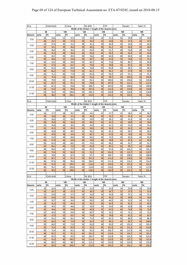
Page 69 of 124 of European Technical Assessment no. ETA-07/0245, issued on 2018-08-15
R1,k CNA4.0x50 2‐Row SD: Ø10 C24 Header
Dowels nails Fk nails Fk nails Fk nails Fk nails Fk nails Fk
20 19,6 22 22,5 22 23,9 24 27,3 26 29,9 26 29,9
28 24,7 30 27,3 30 30,4 32 33,8 34 37,4 34 37,5
24 27,6 26 31,1 28 35,1 30 39,3 32 42,6 32 42,6
32 33,1 34 36,4 36 40,5 38 45,1 40 49,9 40 50,0
28 36,0 30 40,2 32 44,9 36 51,7 38 55,8 38 55,8
36 41,4 38 45,6 40 50,6 44 56,3 46 62,4 46 62,6
32 44,7 34 49,5 38 56,6 40 62,4 44 69,3 44 69,3
40 49,6 42 54,6 46 60,7 48 67,6 52 74,8 52 75,1
36 53,5 38 58,9 42 66,7 46 75,0 48 80,7 50 82,8
44 57,9 46 63,7 50 70,9 54 78,8 56 87,2 58 87,5
40 62,3 44 69,9 46 76,9 50 85,9 50 90,1 50 90,1
48 66,2 52 72,9 54 81,1 58 90,1 58 97,9 58 97,9
44 71,1 46 77,8 50 87,0 50 93,5 50 97,1 50 97,1
52 74,4 54 82,0 58 91,2 58 99,7 58 105,9 58 105,9
48 79,9 50 87,3 50 94,1 50 100,6 50 103,6 50 103,6
56 82,7 58 91,1 58 99,8 58 107,9 58 113,1 58 113,1
50 87,4 50 93,8 50 100,7 50 107,0 50 109,0 50 109,0
58 91,0 58 99,0 58 107,4 58 115,4 58 119,8 58 119,8
50 93,4 50 100,0 50 106,7 50 110,8 50 110,8 50 110,8
58 98,3 58 106,1 58 114,5 58 122,2 58 125,5 58 125,5
R1,k CNA4.0x60 2‐Row SD: Ø10 C24 Header
Dowels nails Fk nails Fk nails Fk nails Fk nails Fk nails Fk
16 17,7 18 20,7 20 24,1 22 27,7 22 28,2 24 30,7
24 24,8 26 27,3 28 30,3 30 33,7 30 37,3 32 37,4
20 26,0 22 29,7 24 33,8 26 38,1 28 41,4 28 41,4
28 33,0 30 36,4 32 40,5 34 45,1 36 49,9 36 50,0
24 34,8 26 39,1 28 43,9 32 51,1 34 55,3 34 55,3
32 41,3 34 45,5 36 50,6 40 56,3 42 62,3 42 62,6
28 43,8 30 48,7 34 56,2 36 62,1 40 69,2 40 69,2
36 49,6 38 54,6 42 60,7 44 67,6 48 74,8 48 75,0
32 52,9 34 58,4 38 66,5 40 73,2 44 81,0 44 81,0
40 57,9 42 63,8 46 70,9 48 78,8 52 87,3 52 87,6
36 62,0 38 68,1 42 76,9 46 86,2 48 92,7 48 92,7
44 66,1 46 72,9 50 81,0 54 90,1 56 99,7 56 100,0
38 69,4 42 77,9 46 87,3 50 97,4 50 102,1 50 102,1
46 74,4 50 82,0 54 91,2 58 101,4 58 110,7 58 110,7
42 78,6 46 87,5 50 97,7 50 104,7 50 108,6 50 108,6
50 82,7 54 91,1 58 101,3 58 111,4 58 118,6 58 118,6
46 87,6 48 95,6 50 104,5 50 111,3 50 114,2 50 114,2
54 91,0 56 100,2 58 110,6 58 119,6 58 125,4 58 125,4
48 95,1 50 103,6 50 110,8 50 116,6 50 117,9 50 117,9
56 99,3 58 108,9 58 118,3 58 126,9 58 131,3 58 131,3
R1,k CSA5.0x50 2‐Row SD: Ø10 C24 Header
Dowels nails Fk nails Fk nails Fk nails Fk nails Fk nails Fk
10 16,5 10 17,4 12 21,4 12 22,4 14 25,8 14 25,8
16 24,7 18 27,3 20 30,3 20 33,7 22 37,3 22 37,4
12 23,0 14 27,3 16 31,9 16 33,4 18 37,1 18 37,1
20 33,0 22 36,4 24 40,5 24 45,1 26 49,8 26 50,0
16 32,7 16 34,3 18 39,3 20 44,5 24 52,3 24 52,3
24 41,3 24 45,5 26 50,7 28 56,3 32 62,3 32 62,5
18 39,5 20 44,6 22 50,0 24 55,6 28 63,8 28 63,8
26 49,6 28 54,6 30 60,8 32 67,5 36 74,8 36 75,0
22 49,4 24 54,9 26 60,7 30 70,1 32 75,1 32 75,1
30 57,9 32 63,7 34 70,9 38 78,8 40 87,2 40 87,5
24 56,1 28 65,1 30 71,3 34 81,1 36 86,3 36 86,3
32 66,2 36 72,9 38 81,0 42 90,1 44 99,7 44 100,0
28 66,0 30 72,0 34 81,8 38 92,0 42 101,4 42 101,4
36 74,4 38 82,0 42 91,2 46 101,4 50 112,2 50 112,6
30 72,4 34 82,1 38 92,3 42 102,7 46 112,3 46 112,3
38 82,7 42 91,1 46 101,3 50 112,6 54 124,7 54 125,1
34 82,3 38 92,2 42 102,7 46 113,4 50 123,2 50 123,2
42 91,0 46 100,2 50 111,4 54 123,9 58 137,1 58 137,4
36 88,5 40 98,7 46 113,1 50 123,9 50 125,0 50 125,0
44 99,3 48 109,3 54 121,6 58 135,2 58 142,1 58 142,1
Width of the timber = length of the dowels (mm)
Table 73
80 100 120 140 160 180
3 SD
4 SD
5 SD
6 SD
7 SD
8 SD
9 SD
10 SD
Width of the timber = length of the dowels (mm)
11 SD
12 SD
Table 74
80 100 120 140 160 180
3 SD
4 SD
5 SD
6 SD
7 SD
8 SD
9 SD
10 SD
Width of the timber = length of the dowels (mm)
11 SD
12 SD
Table 75
80 100 120 140 160 180
3 SD
4 SD
5 SD
6 SD
7 SD
8 SD
9 SD
10 SD
11 SD
12 SD
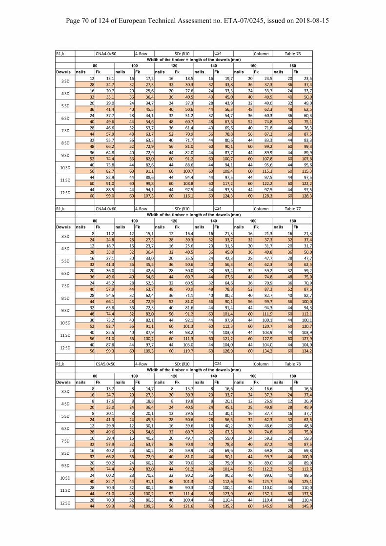
Page 70 of 124 of European Technical Assessment no. ETA-07/0245, issued on 2018-08-15
R1,k CNA4.0x50 4‐Row SD: Ø10 C24 Column
Dowels nails Fk nails Fk nails Fk nails Fk nails Fk nails Fk
12 13,1 16 17,2 16 18,5 16 19,7 20 23,5 20 23,5
28 24,7 32 27,3 32 30,3 32 33,8 36 37,3 36 37,4
16 20,7 20 25,6 20 27,6 24 33,3 24 33,7 24 33,7
32 33,1 36 36,4 36 40,5 40 45,0 40 49,9 40 50,0
20 29,0 24 34,7 24 37,3 28 43,9 32 49,0 32 49,0
36 41,4 40 45,5 40 50,6 44 56,3 48 62,3 48 62,5
24 37,7 28 44,1 32 51,2 32 54,7 36 60,3 36 60,3
40 49,6 44 54,6 48 60,7 48 67,6 52 74,8 52 75,1
28 46,6 32 53,7 36 61,4 40 69,6 40 71,8 44 76,3
44 57,9 48 63,7 52 70,9 56 78,8 56 87,2 60 87,5
32 55,7 36 63,3 40 71,7 44 80,6 44 83,3 44 83,3
48 66,2 52 72,9 56 81,0 60 90,1 60 99,2 60 99,3
36 64,8 40 72,9 44 82,0 44 87,7 44 89,9 44 89,9
52 74,4 56 82,0 60 91,2 60 100,7 60 107,8 60 107,8
40 73,8 44 82,6 44 88,6 44 94,1 44 95,6 44 95,6
56 82,7 60 91,1 60 100,7 60 109,4 60 115,3 60 115,3
44 82,9 44 88,6 44 94,4 44 97,5 44 97,5 44 97,5
60 91,0 60 99,8 60 108,8 60 117,2 60 122,2 60 122,2
44 88,5 44 94,1 44 97,5 44 97,5 44 97,5 44 97,5
60 99,0 60 107,3 60 116,1 60 124,3 60 128,3 60 128,3
R1,k CNA4.0x60 4‐Row SD: Ø10 C24 Column
Dowels nails Fk nails Fk nails Fk nails Fk nails Fk nails Fk
8 11,2 12 15,1 12 16,4 16 21,3 16 21,3 16 21,3
24 24,8 28 27,3 28 30,3 32 33,7 32 37,3 32 37,4
12 18,7 16 23,7 16 25,6 20 31,5 20 31,7 20 31,7
28 33,0 32 36,4 32 40,5 36 45,0 36 49,8 36 50,0
16 27,1 20 33,0 20 35,5 24 42,3 28 47,7 28 47,7
32 41,3 36 45,5 36 50,6 40 56,3 44 62,3 44 62,5
20 36,0 24 42,6 28 50,0 28 53,4 32 59,2 32 59,2
36 49,6 40 54,6 44 60,7 44 67,6 48 74,8 48 75,0
24 45,2 28 52,5 32 60,5 32 64,6 36 70,9 36 70,9
40 57,9 44 63,7 48 70,9 48 78,8 52 87,3 52 87,6
28 54,5 32 62,4 36 71,1 40 80,2 40 82,7 40 82,7
44 66,1 48 72,9 52 81,0 56 90,1 56 99,7 56 100,0
32 63,8 36 72,3 40 81,6 44 91,4 44 94,3 44 94,3
48 74,4 52 82,0 56 91,2 60 101,4 60 111,9 60 112,1
36 73,2 40 82,1 44 92,1 44 97,9 44 100,1 44 100,1
52 82,7 56 91,1 60 101,3 60 112,3 60 120,7 60 120,7
40 82,5 40 87,9 44 98,2 44 103,0 44 103,9 44 103,9
56 91,0 56 100,2 60 111,3 60 121,2 60 127,9 60 127,9
40 87,8 44 97,7 44 103,0 44 104,0 44 104,0 44 104,0
56 99,3 60 109,3 60 119,7 60 128,9 60 134,2 60 134,2
R1,k CSA5.0x50 4‐Row SD: Ø10 C24 Column
Dowels nails Fk nails Fk nails Fk nails Fk nails Fk nails Fk
8 13,7 8 14,7 8 15,7 8 16,6 8 16,6 8 16,6
16 24,7 20 27,3 20 30,3 20 33,7 24 37,3 24 37,4
8 17,6 8 18,8 8 19,8 8 20,1 12 26,9 12 26,9
20 33,0 24 36,4 24 40,5 24 45,1 28 49,8 28 49,9
8 20,1 8 20,1 12 29,5 12 30,1 16 37,7 16 37,7
24 41,3 24 45,5 28 50,6 28 56,3 32 62,3 32 62,5
12 29,9 12 30,1 16 39,6 16 40,2 20 48,6 20 48,6
28 49,6 28 54,6 32 60,7 32 67,5 36 74,8 36 75,0
16 39,4 16 40,2 20 49,7 24 59,0 24 59,3 24 59,3
32 57,9 32 63,7 36 70,9 40 78,8 40 87,2 40 87,5
16 40,2 20 50,2 24 59,9 28 69,6 28 69,8 28 69,8
32 66,2 36 72,9 40 81,0 44 90,1 44 99,7 44 100,0
20 50,2 24 60,2 28 70,0 32 79,9 36 89,0 36 89,0
36 74,4 40 82,0 44 91,2 48 101,4 52 112,2 52 112,6
24 60,2 28 70,2 32 80,2 36 90,2 40 99,6 40 99,6
40 82,7 44 91,1 48 101,3 52 112,6 56 124,7 56 125,1
28 70,3 32 80,2 36 90,3 40 100,4 44 110,0 44 110,0
44 91,0 48 100,2 52 111,4 56 123,9 60 137,1 60 137,6
28 70,3 32 80,3 40 100,4 44 110,4 44 110,4 44 110,4
44 99,3 48 109,3 56 121,6 60 135,2 60 145,9 60 145,9
Width of the timber = length of the dowels (mm)
Table 76
80 100 120 140 160 180
3 SD
4 SD
5 SD
6 SD
7 SD
8 SD
9 SD
10 SD
Width of the timber = length of the dowels (mm)
11 SD
12 SD
Table 77
80 100 120 140 160 180
3 SD
4 SD
5 SD
6 SD
7 SD
8 SD
9 SD
10 SD
Width of the timber = length of the dowels (mm)
11 SD
12 SD
Table 78
80 100 120 140 160 180
3 SD
4 SD
5 SD
6 SD
7 SD
8 SD
9 SD
10 SD
11 SD
12 SD
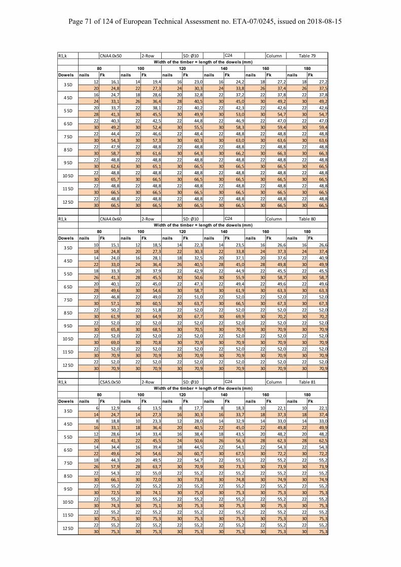
Page 71 of 124 of European Technical Assessment no. ETA-07/0245, issued on 2018-08-15
R1,k CNA4.0x50 2‐Row SD: Ø10 C24 Column
Dowels nails Fk nails Fk nails Fk nails Fk nails Fk nails Fk
12 16,1 14 19,4 16 23,0 16 24,2 18 27,2 18 27,2
20 24,8 22 27,3 24 30,3 24 33,8 26 37,4 26 37,5
16 24,7 18 28,6 20 32,8 22 37,2 22 37,8 22 37,8
24 33,1 26 36,4 28 40,5 30 45,0 30 49,2 30 49,2
20 33,7 22 38,1 22 40,2 22 42,3 22 42,6 22 42,6
28 41,3 30 45,5 30 49,9 30 53,0 30 54,7 30 54,7
22 40,3 22 42,5 22 44,8 22 46,9 22 47,0 22 47,0
30 49,2 30 52,4 30 55,5 30 58,3 30 59,4 30 59,4
22 44,4 22 46,6 22 48,4 22 48,8 22 48,8 22 48,8
30 54,3 30 57,3 30 60,3 30 63,0 30 63,6 30 63,6
22 47,9 22 48,8 22 48,8 22 48,8 22 48,8 22 48,8
30 58,7 30 61,6 30 64,3 30 66,2 30 66,3 30 66,3
22 48,8 22 48,8 22 48,8 22 48,8 22 48,8 22 48,8
30 62,6 30 65,1 30 66,5 30 66,5 30 66,5 30 66,5
22 48,8 22 48,8 22 48,8 22 48,8 22 48,8 22 48,8
30 65,7 30 66,5 30 66,5 30 66,5 30 66,5 30 66,5
22 48,8 22 48,8 22 48,8 22 48,8 22 48,8 22 48,8
30 66,5 30 66,5 30 66,5 30 66,5 30 66,5 30 66,5
22 48,8 22 48,8 22 48,8 22 48,8 22 48,8 22 48,8
30 66,5 30 66,5 30 66,5 30 66,5 30 66,5 30 66,5
R1,k CNA4.0x60 2‐Row SD: Ø10 C24 Column
Dowels nails Fk nails Fk nails Fk nails Fk nails Fk nails Fk
10 15,1 12 18,5 14 22,3 14 23,5 16 26,6 16 26,6
18 24,8 20 27,3 22 30,3 22 33,8 24 37,3 24 37,4
14 24,0 16 28,1 18 32,5 20 37,1 20 37,6 22 40,9
22 33,0 24 36,4 26 40,5 28 45,0 28 49,8 30 49,9
18 33,3 20 37,9 22 42,9 22 44,9 22 45,5 22 45,5
26 41,3 28 45,5 30 50,6 30 55,9 30 58,7 30 58,7
20 40,1 22 45,0 22 47,3 22 49,4 22 49,6 22 49,6
28 49,6 30 54,6 30 58,7 30 61,9 30 63,3 30 63,3
22 46,8 22 49,0 22 51,0 22 52,0 22 52,0 22 52,0
30 57,1 30 60,5 30 63,7 30 66,5 30 67,3 30 67,3
22 50,2 22 51,8 22 52,0 22 52,0 22 52,0 22 52,0
30 61,9 30 64,9 30 67,7 30 69,9 30 70,2 30 70,2
22 52,0 22 52,0 22 52,0 22 52,0 22 52,0 22 52,0
30 65,8 30 68,5 30 70,5 30 70,9 30 70,9 30 70,9
22 52,0 22 52,0 22 52,0 22 52,0 22 52,0 22 52,0
30 69,0 30 70,8 30 70,9 30 70,9 30 70,9 30 70,9
22 52,0 22 52,0 22 52,0 22 52,0 22 52,0 22 52,0
30 70,9 30 70,9 30 70,9 30 70,9 30 70,9 30 70,9
22 52,0 22 52,0 22 52,0 22 52,0 22 52,0 22 52,0
30 70,9 30 70,9 30 70,9 30 70,9 30 70,9 30 70,9
R1,k CSA5.0x50 2‐Row SD: Ø10 C24 Column
Dowels nails Fk nails Fk nails Fk nails Fk nails Fk nails Fk
6 12,9 6 13,5 8 17,7 8 18,3 10 22,1 10 22,1
14 24,7 14 27,3 16 30,3 16 33,7 18 37,3 18 37,4
8 18,8 10 23,3 12 28,0 14 32,9 14 33,0 14 33,0
16 33,1 18 36,4 20 40,5 22 45,0 22 49,8 22 49,9
12 28,6 14 33,4 16 38,4 18 43,5 20 48,2 20 48,2
20 41,3 22 45,5 24 50,6 26 56,3 28 62,3 28 62,5
14 34,4 16 39,4 18 44,5 22 54,1 22 54,3 22 54,3
22 49,6 24 54,6 26 60,7 30 67,5 30 72,2 30 72,2
18 44,3 20 49,5 22 54,7 22 55,1 22 55,2 22 55,2
26 57,9 28 63,7 30 70,9 30 73,3 30 73,9 30 73,9
22 54,3 22 55,0 22 55,2 22 55,2 22 55,2 22 55,2
30 66,1 30 72,0 30 73,8 30 74,8 30 74,9 30 74,9
22 55,2 22 55,2 22 55,2 22 55,2 22 55,2 22 55,2
30 72,5 30 74,1 30 75,0 30 75,3 30 75,3 30 75,3
22 55,2 22 55,2 22 55,2 22 55,2 22 55,2 22 55,2
30 74,3 30 75,1 30 75,3 30 75,3 30 75,3 30 75,3
22 55,2 22 55,2 22 55,2 22 55,2 22 55,2 22 55,2
30 75,1 30 75,3 30 75,3 30 75,3 30 75,3 30 75,3
22 55,2 22 55,2 22 55,2 22 55,2 22 55,2 22 55,2
30 75,3 30 75,3 30 75,3 30 75,3 30 75,3 30 75,3
Table 79Width of the timber = length of the dowels (mm)
80 100 120 140 160 180
3 SD
4 SD
5 SD
6 SD
7 SD
8 SD
9 SD
10 SD
Table 80Width of the timber = length of the dowels (mm)
11 SD
12 SD
80 100 120 140 160 180
3 SD
4 SD
5 SD
6 SD
7 SD
8 SD
9 SD
10 SD
Table 81Width of the timber = length of the dowels (mm)
11 SD
12 SD
80 100 120 140 160 180
3 SD
4 SD
5 SD
6 SD
7 SD
8 SD
9 SD
10 SD
11 SD
12 SD
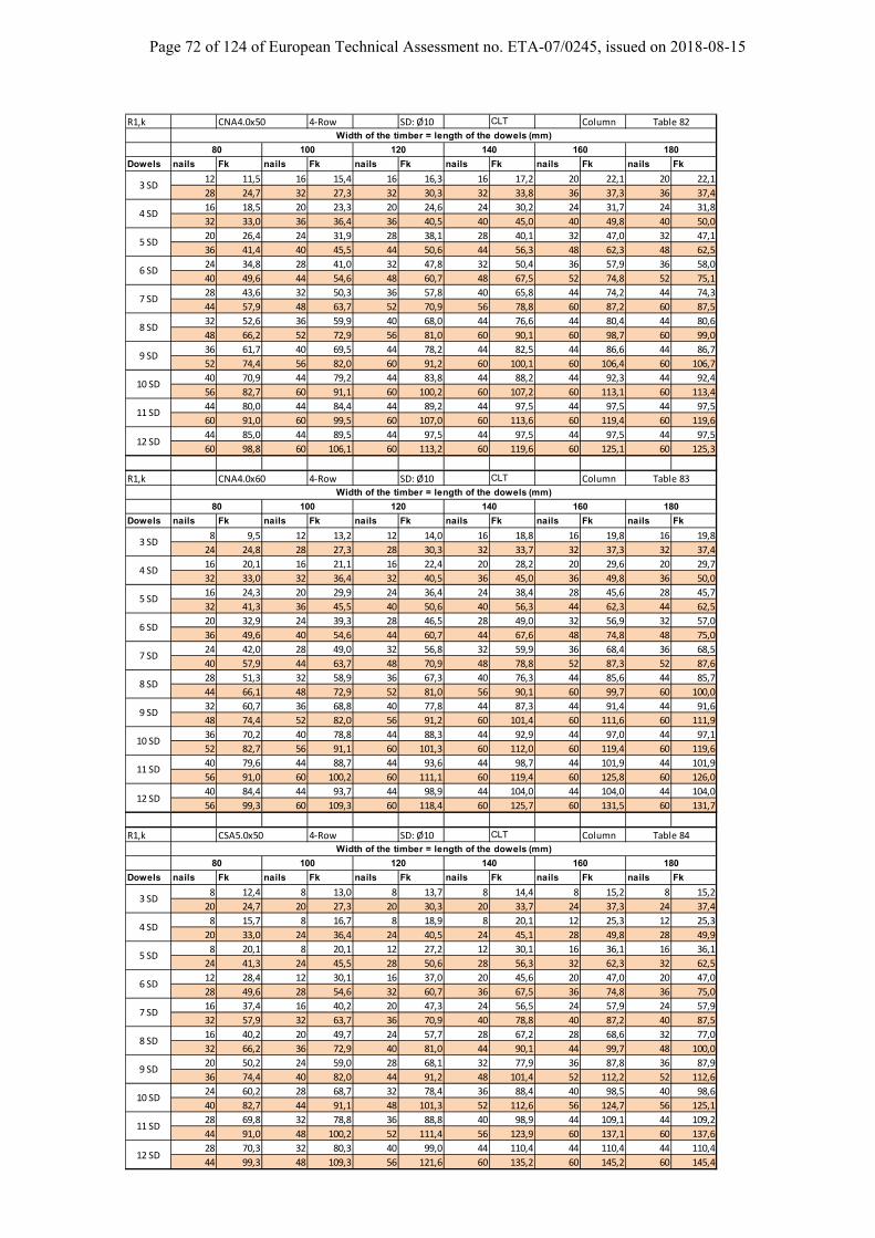
Page 72 of 124 of European Technical Assessment no. ETA-07/0245, issued on 2018-08-15
R1,k CNA4.0x50 4‐Row SD: Ø10 CLT Column
Dowels nails Fk nails Fk nails Fk nails Fk nails Fk nails Fk
12 11,5 16 15,4 16 16,3 16 17,2 20 22,1 20 22,1
28 24,7 32 27,3 32 30,3 32 33,8 36 37,3 36 37,4
16 18,5 20 23,3 20 24,6 24 30,2 24 31,7 24 31,8
32 33,0 36 36,4 36 40,5 40 45,0 40 49,8 40 50,0
20 26,4 24 31,9 28 38,1 28 40,1 32 47,0 32 47,1
36 41,4 40 45,5 44 50,6 44 56,3 48 62,3 48 62,5
24 34,8 28 41,0 32 47,8 32 50,4 36 57,9 36 58,0
40 49,6 44 54,6 48 60,7 48 67,5 52 74,8 52 75,1
28 43,6 32 50,3 36 57,8 40 65,8 44 74,2 44 74,3
44 57,9 48 63,7 52 70,9 56 78,8 60 87,2 60 87,5
32 52,6 36 59,9 40 68,0 44 76,6 44 80,4 44 80,6
48 66,2 52 72,9 56 81,0 60 90,1 60 98,7 60 99,0
36 61,7 40 69,5 44 78,2 44 82,5 44 86,6 44 86,7
52 74,4 56 82,0 60 91,2 60 100,1 60 106,4 60 106,7
40 70,9 44 79,2 44 83,8 44 88,2 44 92,3 44 92,4
56 82,7 60 91,1 60 100,2 60 107,2 60 113,1 60 113,4
44 80,0 44 84,4 44 89,2 44 97,5 44 97,5 44 97,5
60 91,0 60 99,5 60 107,0 60 113,6 60 119,4 60 119,6
44 85,0 44 89,5 44 97,5 44 97,5 44 97,5 44 97,5
60 98,8 60 106,1 60 113,2 60 119,6 60 125,1 60 125,3
R1,k CNA4.0x60 4‐Row SD: Ø10 CLT Column
Dowels nails Fk nails Fk nails Fk nails Fk nails Fk nails Fk
8 9,5 12 13,2 12 14,0 16 18,8 16 19,8 16 19,8
24 24,8 28 27,3 28 30,3 32 33,7 32 37,3 32 37,4
16 20,1 16 21,1 16 22,4 20 28,2 20 29,6 20 29,7
32 33,0 32 36,4 32 40,5 36 45,0 36 49,8 36 50,0
16 24,3 20 29,9 24 36,4 24 38,4 28 45,6 28 45,7
32 41,3 36 45,5 40 50,6 40 56,3 44 62,3 44 62,5
20 32,9 24 39,3 28 46,5 28 49,0 32 56,9 32 57,0
36 49,6 40 54,6 44 60,7 44 67,6 48 74,8 48 75,0
24 42,0 28 49,0 32 56,8 32 59,9 36 68,4 36 68,5
40 57,9 44 63,7 48 70,9 48 78,8 52 87,3 52 87,6
28 51,3 32 58,9 36 67,3 40 76,3 44 85,6 44 85,7
44 66,1 48 72,9 52 81,0 56 90,1 60 99,7 60 100,0
32 60,7 36 68,8 40 77,8 44 87,3 44 91,4 44 91,6
48 74,4 52 82,0 56 91,2 60 101,4 60 111,6 60 111,9
36 70,2 40 78,8 44 88,3 44 92,9 44 97,0 44 97,1
52 82,7 56 91,1 60 101,3 60 112,0 60 119,4 60 119,6
40 79,6 44 88,7 44 93,6 44 98,7 44 101,9 44 101,9
56 91,0 60 100,2 60 111,1 60 119,4 60 125,8 60 126,0
40 84,4 44 93,7 44 98,9 44 104,0 44 104,0 44 104,0
56 99,3 60 109,3 60 118,4 60 125,7 60 131,5 60 131,7
R1,k CSA5.0x50 4‐Row SD: Ø10 CLT Column
Dowels nails Fk nails Fk nails Fk nails Fk nails Fk nails Fk
8 12,4 8 13,0 8 13,7 8 14,4 8 15,2 8 15,2
20 24,7 20 27,3 20 30,3 20 33,7 24 37,3 24 37,4
8 15,7 8 16,7 8 18,9 8 20,1 12 25,3 12 25,3
20 33,0 24 36,4 24 40,5 24 45,1 28 49,8 28 49,9
8 20,1 8 20,1 12 27,2 12 30,1 16 36,1 16 36,1
24 41,3 24 45,5 28 50,6 28 56,3 32 62,3 32 62,5
12 28,4 12 30,1 16 37,0 20 45,6 20 47,0 20 47,0
28 49,6 28 54,6 32 60,7 36 67,5 36 74,8 36 75,0
16 37,4 16 40,2 20 47,3 24 56,5 24 57,9 24 57,9
32 57,9 32 63,7 36 70,9 40 78,8 40 87,2 40 87,5
16 40,2 20 49,7 24 57,7 28 67,2 28 68,6 32 77,0
32 66,2 36 72,9 40 81,0 44 90,1 44 99,7 48 100,0
20 50,2 24 59,0 28 68,1 32 77,9 36 87,8 36 87,9
36 74,4 40 82,0 44 91,2 48 101,4 52 112,2 52 112,6
24 60,2 28 68,7 32 78,4 36 88,4 40 98,5 40 98,6
40 82,7 44 91,1 48 101,3 52 112,6 56 124,7 56 125,1
28 69,8 32 78,8 36 88,8 40 98,9 44 109,1 44 109,2
44 91,0 48 100,2 52 111,4 56 123,9 60 137,1 60 137,6
28 70,3 32 80,3 40 99,0 44 110,4 44 110,4 44 110,4
44 99,3 48 109,3 56 121,6 60 135,2 60 145,2 60 145,4
Table 82
Width of the timber = length of the dowels (mm)
80 100 120 140 160 180
3 SD
4 SD
5 SD
6 SD
7 SD
8 SD
9 SD
10 SD
Table 83
Width of the timber = length of the dowels (mm)
11 SD
12 SD
80 100 120 140 160 180
3 SD
4 SD
5 SD
6 SD
7 SD
8 SD
9 SD
10 SD
Table 84
Width of the timber = length of the dowels (mm)
11 SD
12 SD
80 100 120 140 160 180
3 SD
4 SD
5 SD
6 SD
7 SD
8 SD
9 SD
10 SD
11 SD
12 SD
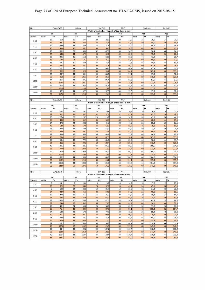
Page 73 of 124 of European Technical Assessment no. ETA-07/0245, issued on 2018-08-15
R1,k CNA4.0x50 4‐Row SD: Ø10 CLT Column
Dowels nails Fk nails Fk nails Fk nails Fk nails Fk nails Fk
16 16,8 16 17,4 20 22,1 20 23,0 24 28,6 24 29,6
32 32,2 32 34,5 36 37,6 36 41,2 40 45,0 40 49,2
24 29,6 24 30,6 24 31,8 28 38,0 32 44,7 32 46,3
40 43,0 40 46,1 40 50,1 44 54,9 48 60,0 48 65,5
28 39,2 28 40,6 32 47,1 36 54,3 36 56,4 40 64,1
44 53,8 44 57,7 48 62,7 52 68,6 52 75,2 56 81,9
32 49,3 36 55,8 36 58,1 40 65,8 44 73,9 44 76,7
48 64,6 52 69,2 52 75,3 56 82,4 60 90,1 60 97,5
36 59,7 40 66,6 44 74,4 44 77,6 44 80,7 44 83,8
52 75,5 56 80,7 60 87,8 60 96,0 60 101,8 60 106,2
40 70,1 44 77,5 44 80,7 44 84,1 44 87,4 44 90,6
56 86,2 60 92,2 60 99,2 60 104,7 60 109,4 60 113,6
44 80,7 44 83,4 44 86,8 44 91,1 44 97,5 44 97,5
60 96,8 60 101,7 60 106,9 60 111,8 60 116,3 60 120,4
44 86,4 44 89,2 44 95,4 44 97,5 44 97,5 44 97,5
60 104,4 60 108,7 60 113,5 60 118,3 60 122,7 60 126,6
44 91,8 44 97,5 44 97,5 44 97,5 44 97,5 44 97,5
60 111,0 60 115,0 60 119,8 60 124,4 60 132,5 60 133,0
44 97,5 44 97,5 44 97,5 44 97,5 44 97,5 44 97,5
60 117,0 60 121,0 60 125,4 60 133,0 60 133,0 60 133,0
R1,k CNA4.0x60 4‐Row SD: Ø10 CLT Column
Dowels nails Fk nails Fk nails Fk nails Fk nails Fk nails Fk
12 14,5 16 19,1 16 19,8 16 20,7 20 26,5 20 27,5
28 32,3 32 34,5 32 37,6 32 41,1 36 45,0 36 49,2
20 27,6 20 28,5 20 29,7 24 36,2 28 43,3 28 44,8
36 43,0 36 46,1 36 50,1 40 54,9 44 60,0 44 65,5
24 37,5 24 38,8 28 45,7 28 47,6 32 55,3 36 63,5
40 53,8 40 57,6 44 62,7 44 68,7 48 75,1 52 81,9
28 47,9 28 49,6 32 57,1 36 65,2 40 73,7 40 76,3
44 64,6 44 69,2 48 75,3 52 82,4 56 90,1 56 98,4
32 58,6 36 66,0 36 68,6 40 77,2 44 86,3 44 89,3
48 75,4 52 80,7 52 87,9 56 96,1 60 105,2 60 113,0
36 69,4 40 77,1 44 85,8 44 89,3 44 92,6 44 95,7
52 86,2 56 92,2 60 100,4 60 109,8 60 116,2 60 121,0
40 80,2 44 88,3 44 91,7 44 95,2 44 100,5 44 104,0
56 97,0 60 103,8 60 112,2 60 118,4 60 123,4 60 127,7
44 91,0 44 93,9 44 97,2 44 104,0 44 104,0 44 104,0
60 107,8 60 114,0 60 119,9 60 125,1 60 129,7 60 133,7
44 96,2 44 99,0 44 104,0 44 104,0 44 104,0 44 104,0
60 116,3 60 121,0 60 126,2 60 131,1 60 135,3 60 139,2
44 101,8 44 104,0 44 104,0 44 104,0 44 104,0 44 104,0
60 122,8 60 127,1 60 131,9 60 136,3 60 141,8 60 141,8
R1,k CSA5.0x50 4‐Row SD: Ø10 CLT Column
Dowels nails Fk nails Fk nails Fk nails Fk nails Fk nails Fk
8 14,1 8 14,6 8 15,2 8 16,2 8 17,7 12 23,5
20 32,2 20 34,6 24 37,6 24 41,1 24 45,1 28 49,1
8 19,0 12 24,5 12 25,4 12 26,3 16 34,2 16 35,2
24 43,0 28 46,1 28 50,1 28 54,9 32 60,0 32 65,5
12 27,6 16 35,1 16 36,2 20 44,7 20 45,8 24 54,9
28 53,8 32 57,6 32 62,7 36 68,6 36 75,1 40 81,9
16 37,8 20 46,0 20 47,1 24 56,1 28 65,5 28 66,7
32 64,6 36 69,2 36 75,3 40 82,4 44 90,1 44 98,3
20 48,1 24 56,8 24 58,0 28 67,3 32 77,0 36 86,8
36 75,4 40 80,7 40 87,9 44 96,1 48 105,2 52 114,7
24 58,5 28 67,6 32 77,1 32 78,3 36 88,2 40 98,1
40 86,2 44 92,2 48 100,4 48 109,9 52 120,3 56 131,2
28 68,9 32 78,2 36 87,9 40 97,9 44 108,0 44 109,1
44 97,0 48 103,8 52 113,0 56 123,6 60 135,3 60 144,2
32 79,3 36 88,8 40 98,6 44 108,7 44 110,4 44 110,4
48 107,8 52 115,3 56 125,5 60 137,4 60 145,0 60 147,2
36 90,4 40 99,2 44 109,2 44 110,4 44 110,4 44 110,4
52 118,5 56 126,9 60 138,1 60 145,4 60 147,7 60 149,1
40 100,4 44 110,4 44 110,4 44 110,4 44 110,4 44 110,4
56 129,3 60 138,4 60 145,5 60 148,0 60 149,5 60 150,6
8 SD
Table 85Width of the timber = length of the dowels (mm)
80 100 120 140 160 180
3 SD
4 SD
5 SD
6 SD
7 SD
160 180
9 SD
10 SD
11 SD
12 SD
Table 86Width of the timber = length of the dowels (mm)
8 SD
80 100 120 140
3 SD
4 SD
5 SD
6 SD
7 SD
180
9 SD
10 SD
11 SD
12 SD
Table 87Width of the timber = length of the dowels (mm)
80 100 120 140 160
9 SD
10 SD
11 SD
12 SD
3 SD
4 SD
5 SD
6 SD
7 SD
8 SD
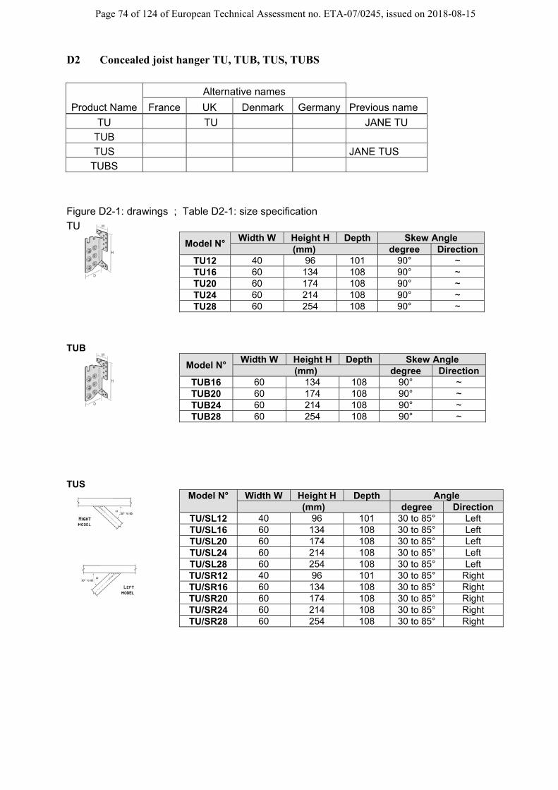
Page 74 of 124 of European Technical Assessment no. ETA-07/0245, issued on 2018-08-15
D2 Concealed joist hanger TU, TUB, TUS, TUBS
Product Name
Alternative names
France UK Denmark Germany Previous name
TU TU JANE TU
TUB
TUS JANE TUS
TUBS
Figure D2-1: drawings ; Table D2-1: size specification
TU
Model N° Width W Height H Depth Skew Angle
(mm) degree Direction TU12 40 96 101 90° ~ TU16 60 134 108 90° ~ TU20 60 174 108 90° ~ TU24 60 214 108 90° ~ TU28 60 254 108 90° ~
TUB Model N°
Width W Height H Depth Skew Angle (mm) degree Direction
TUB16 60 134 108 90° ~ TUB20 60 174 108 90° ~ TUB24 60 214 108 90° ~ TUB28 60 254 108 90° ~
TUS
Model N° Width W Height H Depth Angle (mm) degree Direction
TU/SL12 40 96 101 30 to 85° Left TU/SL16 60 134 108 30 to 85° Left TU/SL20 60 174 108 30 to 85° Left TU/SL24 60 214 108 30 to 85° Left TU/SL28 60 254 108 30 to 85° Left TU/SR12 40 96 101 30 to 85° Right TU/SR16 60 134 108 30 to 85° Right TU/SR20 60 174 108 30 to 85° Right TU/SR24 60 214 108 30 to 85° Right TU/SR28 60 254 108 30 to 85° Right

Page 75 of 124 of European Technical Assessment no. ETA-07/0245, issued on 2018-08-15
TUBS Model N° Width W Height H Depth Angle
(mm) degree Direction TUBSL16 60 134 108 30 to 85° Left TUBSL20 60 174 108 30 to 85° Left TUBSL24 60 214 108 30 to 85° Left TUBSL28 60 254 108 30 to 85° Left TUBSR16 60 134 108 30 to 85° Right TUBSR20 60 174 108 30 to 85° Right TUBSR24 60 214 108 30 to 85° Right TUBSR28 60 254 108 30 to 85° Right
Hanger Type
Header Fasteners Joist Fasteners
Ø4.0 Connector nails Bolt M12 Concrete
screw
Dowels Ø8
Dowels Ø12
TU12 6 ~ 4 ~ TU16 18 ~ ~ 3 TU20 22 ~ ~ 4 TU24 26 ~ ~ 5 TU28 30 ~ ~ 6 TUB16 16 2 ~ 3 TUB20 20 2 ~ 4 TUB24 24 2 ~ 5 TUB28 28 2 ~ 6 TUS 12 6 ~ 4 ~ TUS 16 18 ~ ~ 3 TUS 20 22 ~ ~ 4 TUS 24 26 ~ ~ 5 TUS 28 30 ~ ~ 6 TUBS16 16 2 ~ 3 TUBS20 20 2 ~ 4 TUBS24 24 2 ~ 5 TUBS28 28 2 ~ 6
Table D2-2: Material specification
Material thickness
Material Grades
Coating specification
3 S 250 GD Z275
3 stainless steel as described
For installation for fire justification, see clause B6.
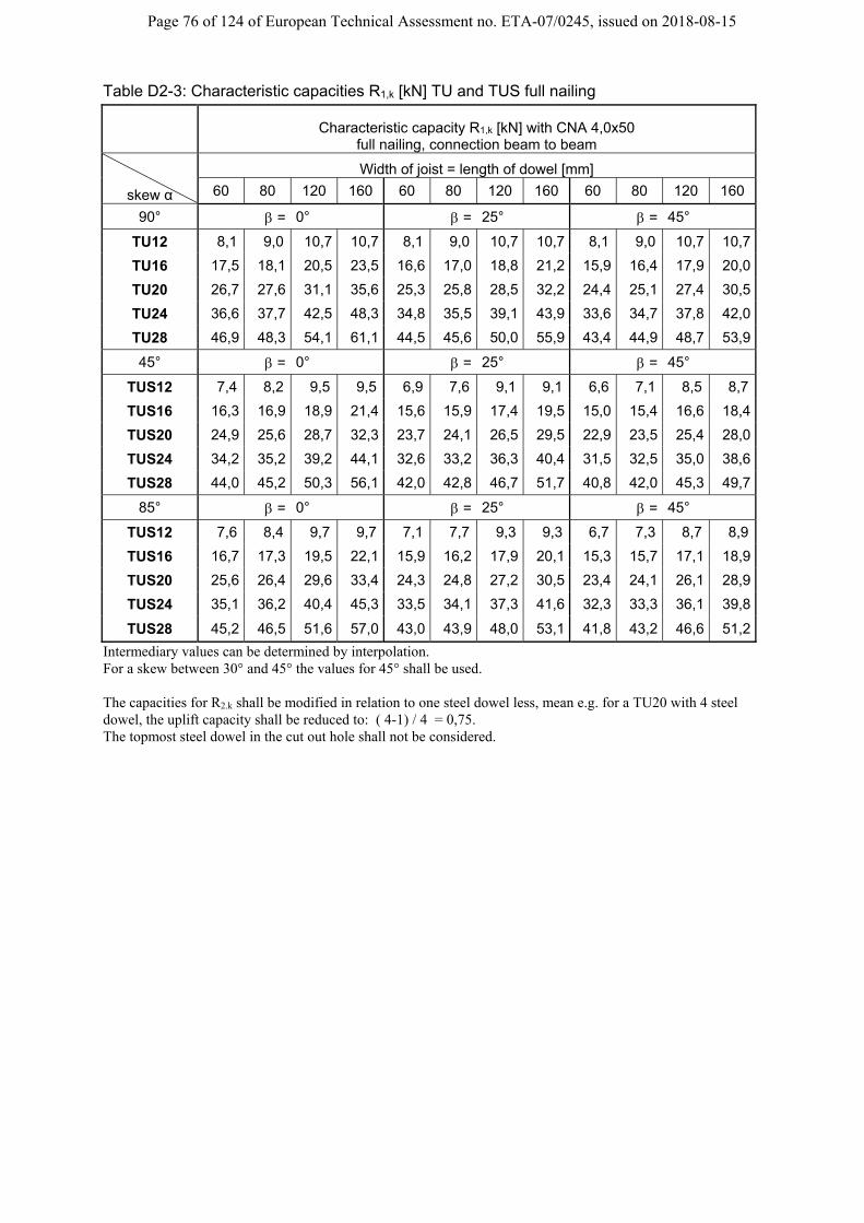
Page 76 of 124 of European Technical Assessment no. ETA-07/0245, issued on 2018-08-15
Table D2-3: Characteristic capacities R1,k [kN] TU and TUS full nailing
Characteristic capacity R1,k [kN] with CNA 4,0x50
full nailing, connection beam to beam
skew α
Width of joist = length of dowel [mm]
60 80 120 160 60 80 120 160 60 80 120 160
90° = 0° = 25° = 45°
TU12 8,1 9,0 10,7 10,7 8,1 9,0 10,7 10,7 8,1 9,0 10,7 10,7
TU16 17,5 18,1 20,5 23,5 16,6 17,0 18,8 21,2 15,9 16,4 17,9 20,0
TU20 26,7 27,6 31,1 35,6 25,3 25,8 28,5 32,2 24,4 25,1 27,4 30,5
TU24 36,6 37,7 42,5 48,3 34,8 35,5 39,1 43,9 33,6 34,7 37,8 42,0
TU28 46,9 48,3 54,1 61,1 44,5 45,6 50,0 55,9 43,4 44,9 48,7 53,9
45° = 0° = 25° = 45°
TUS12 7,4 8,2 9,5 9,5 6,9 7,6 9,1 9,1 6,6 7,1 8,5 8,7
TUS16 16,3 16,9 18,9 21,4 15,6 15,9 17,4 19,5 15,0 15,4 16,6 18,4
TUS20 24,9 25,6 28,7 32,3 23,7 24,1 26,5 29,5 22,9 23,5 25,4 28,0
TUS24 34,2 35,2 39,2 44,1 32,6 33,2 36,3 40,4 31,5 32,5 35,0 38,6
TUS28 44,0 45,2 50,3 56,1 42,0 42,8 46,7 51,7 40,8 42,0 45,3 49,7
85° = 0° = 25° = 45°
TUS12 7,6 8,4 9,7 9,7 7,1 7,7 9,3 9,3 6,7 7,3 8,7 8,9
TUS16 16,7 17,3 19,5 22,1 15,9 16,2 17,9 20,1 15,3 15,7 17,1 18,9
TUS20 25,6 26,4 29,6 33,4 24,3 24,8 27,2 30,5 23,4 24,1 26,1 28,9
TUS24 35,1 36,2 40,4 45,3 33,5 34,1 37,3 41,6 32,3 33,3 36,1 39,8
TUS28 45,2 46,5 51,6 57,0 43,0 43,9 48,0 53,1 41,8 43,2 46,6 51,2
Intermediary values can be determined by interpolation. For a skew between 30° and 45° the values for 45° shall be used. The capacities for R2.k shall be modified in relation to one steel dowel less, mean e.g. for a TU20 with 4 steel dowel, the uplift capacity shall be reduced to: ( 4-1) / 4 = 0,75. The topmost steel dowel in the cut out hole shall not be considered.

Page 77 of 124 of European Technical Assessment no. ETA-07/0245, issued on 2018-08-15
Table D2-4: Characteristic capacities R1,k [kN] TUB and TUBS full nailing
Characteristic capacity R1,k [kN] with CNA 4,0x50 full nailing, connection beam to beam
skew α
Width of joist = length of dowel [mm]
60 80 120 160 60 80 120 160 60 80 120 160
90° = 0° = 25° = 45°
TUB16 16,7 17,3 19,7 22,6 15,7 16,1 17,9 20,4 15,1 15,1 17,0 19,1
TUB20 25,6 26,5 30,0 34,4 24,2 24,7 27,4 31,0 23,3 23,3 26,2 29,3
TUB24 35,3 36,5 41,1 46,8 33,5 34,2 37,7 42,5 32,3 32,3 36,4 40,5
TUB28 45,5 46,9 52,6 59,1 43,1 44,1 48,5 54,3 41,9 41,9 47,1 52,2
45° = 0° = 25° = 45°
TUBS16 15,4 15,9 17,9 20,3 14,6 14,9 16,5 18,5 14,1 14,4 15,6 17,4
TUBS20 23,6 24,4 27,3 30,9 22,4 22,9 25,2 28,2 21,6 22,2 24,1 26,7
TUBS24 32,7 33,7 37,6 42,3 31,1 31,7 34,7 38,7 30,0 30,9 33,4 36,9
TUBS28 42,3 43,5 48,4 53,8 40,4 41,1 44,9 49,8 39,0 40,2 43,4 47,7
85° = 0° = 25° = 45°
TUBS16 15,8 16,4 18,5 21,0 15,0 15,3 17,0 19,1 14,4 14,8 16,1 18,0
TUBS20 24,4 25,2 28,3 31,8 23,1 23,6 26,0 29,1 22,2 22,9 24,9 27,6
TUBS24 33,7 34,8 38,8 43,1 32,1 32,7 35,9 39,9 30,9 31,9 34,6 38,1
TUBS28 43,6 44,8 49,7 53,8 41,5 42,3 46,3 51,0 40,2 41,5 44,9 49,2
Intermediary values can be determined by interpolation. For a skew between 30° and 45° the values for 45° shall be used. The capacities for R2.k shall be modified as described below the table D2-3
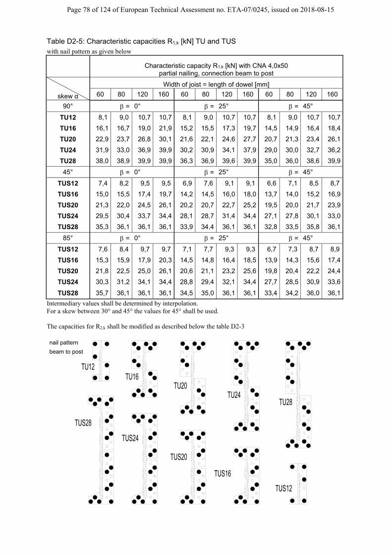
Page 78 of 124 of European Technical Assessment no. ETA-07/0245, issued on 2018-08-15
Table D2-5: Characteristic capacities R1,k [kN] TU and TUS with nail pattern as given below
Characteristic capacity R1,k [kN] with CNA 4,0x50
partial nailing, connection beam to post
skew α
Width of joist = length of dowel [mm]
60 80 120 160 60 80 120 160 60 80 120 160
90° = 0° = 25° = 45°
TU12 8,1 9,0 10,7 10,7 8,1 9,0 10,7 10,7 8,1 9,0 10,7 10,7
TU16 16,1 16,7 19,0 21,9 15,2 15,5 17,3 19,7 14,5 14,9 16,4 18,4
TU20 22,9 23,7 26,8 30,1 21,6 22,1 24,6 27,7 20,7 21,3 23,4 26,1
TU24 31,9 33,0 36,9 39,9 30,2 30,9 34,1 37,9 29,0 30,0 32,7 36,2
TU28 38,0 38,9 39,9 39,9 36,3 36,9 39,6 39,9 35,0 36,0 38,6 39,9
45° = 0° = 25° = 45°
TUS12 7,4 8,2 9,5 9,5 6,9 7,6 9,1 9,1 6,6 7,1 8,5 8,7
TUS16 15,0 15,5 17,4 19,7 14,2 14,5 16,0 18,0 13,7 14,0 15,2 16,9
TUS20 21,3 22,0 24,5 26,1 20,2 20,7 22,7 25,2 19,5 20,0 21,7 23,9
TUS24 29,5 30,4 33,7 34,4 28,1 28,7 31,4 34,4 27,1 27,8 30,1 33,0
TUS28 35,3 36,1 36,1 36,1 33,9 34,4 36,1 36,1 32,8 33,5 35,8 36,1
85° = 0° = 25° = 45°
TUS12 7,6 8,4 9,7 9,7 7,1 7,7 9,3 9,3 6,7 7,3 8,7 8,9
TUS16 15,3 15,9 17,9 20,3 14,5 14,8 16,4 18,5 13,9 14,3 15,6 17,4
TUS20 21,8 22,5 25,0 26,1 20,6 21,1 23,2 25,6 19,8 20,4 22,2 24,4
TUS24 30,3 31,2 34,1 34,4 28,8 29,4 32,1 34,4 27,7 28,5 30,9 33,6
TUS28 35,7 36,1 36,1 36,1 34,5 35,0 36,1 36,1 33,4 34,2 36,0 36,1
Intermediary values shall be determined by interpolation. For a skew between 30° and 45° the values for 45° shall be used. The capacities for R2.k shall be modified as described below the table D2-3
TU24
TU12TU16
TU20
TU28
TUS24
TUS28
TUS12
TUS20
TUS16
beam to post
nail pattern

Page 79 of 124 of European Technical Assessment no. ETA-07/0245, issued on 2018-08-15
Table D2-6: Characteristic capacities R1,k [kN] TUB and TUBS with nail pattern as given below
Characteristic capacity R1,k [kN] with CNA 4,0x50 partial nailing, connection beam to post
skew α
Width of joist = length of dowel [mm]
60 80 120 160 60 80 120 160 60 80 120 160
90° = 0° = 25° = 45°
TUB16 15,2 15,8 18,1 20,8 14,3 14,7 16,4 18,8 13,7 13,7 15,5 17,5
TUB20 21,5 22,3 25,1 26,6 20,3 20,8 23,2 25,8 19,5 19,5 22,0 24,5
TUB24 30,4 31,4 34,8 35,5 28,7 29,4 32,4 35,4 27,5 27,5 31,0 34,1
TUB28 35,3 35,5 35,5 35,5 34,1 34,6 35,5 35,5 33,0 33,0 35,4 35,5
45° = 0° = 25° = 45°
TUBS16 13,9 14,4 16,3 18,5 13,2 13,5 15,0 16,9 12,7 13,0 14,2 15,8
TUBS20 19,8 20,4 22,3 22,3 18,8 19,2 21,1 22,3 18,1 18,5 20,1 22,1
TUBS24 27,7 28,6 30,3 30,3 26,4 26,9 29,5 30,3 25,4 26,1 28,2 30,3
TUBS28 31,9 31,9 31,9 31,9 31,5 31,9 31,9 31,9 30,6 31,2 31,9 31,9
85° = 0° = 25° = 45°
TUBS16 14,3 14,9 16,8 18,9 13,6 13,9 15,5 17,4 13,0 13,3 14,6 16,3
TUBS20 20,2 20,9 22,3 22,3 19,2 19,7 21,5 22,3 18,5 18,9 20,6 22,2
TUBS24 28,4 29,2 30,3 30,3 27,1 27,7 29,9 30,3 26,1 26,8 28,9 30,3
TUBS28 31,9 31,9 31,9 31,9 31,8 31,9 31,9 31,9 31,1 31,6 31,9 31,9
Intermediary values can be determined by interpolation. For a skew between 30° and 45° the values for 45° shall be used. The capacities for R2.k shall be modified as described below the table D2-3
TUB 24
TUB16TUB 20
TUB 28
TUBS24
TUBS28
TUBS20
TUBS16
beam to post
nail pattern

Page 80 of 124 of European Technical Assessment no. ETA-07/0245, issued on 2018-08-15
Table D2-7: Characteristic capacities R3,k [kN] TU
CNA 4,0x40 with screws
number of joist R3, k [kN] for b =
Typ SD nails b / h [mm] 60 80 100 120 140 160 180TU12 4 6 ... / 120 1,6 3,4 4,4 4,4 4,4 4,4 4,4TU16 3 18 ... / 160 1,6 3,1 4,8 6,6 8,3 10,1 11,9TU20 4 22 ... / 200 2,2 3,8 7,0 9,9 12,5 14,9 14,9TU24 5 26 ... / 240 2,7 4,0 7,3 12,0 16,7 16,7 16,7TU28 6 30 ... / 280 3,2 4,4 7,7 12,4 18,6 18,6 18,6
TU12c 4 6 ... / 120 1,6 3,4 4,4 4,4 4,4 4,4 4,4TU16c 3 14 ... / 160 1,6 3,1 4,8 6,6 8,3 10,1 10,7TU20c 4 14 ... / 200 2,2 3,8 7,0 9,9 10,9 10,9 10,9TU24c 5 18 ... / 240 2,7 4,0 7,3 11,9 12,5 12,5 12,5TU28c 6 18 ... / 280 3,2 4,4 7,7 11,9 12,9 12,9 12,9
without screwsTU12 4 6 ... / 120 1,2 1,7 2,2 2,8 3,3 3,8 4,3TU16 3 18 ... / 160 1,6 2,2 2,9 3,6 4,4 5,1 5,7TU20 4 22 ... / 200 2,2 2,9 3,8 4,6 5,6 6,4 7,3TU24 5 26 ... / 240 2,7 3,6 4,7 5,8 6,7 7,9 8,8TU28 6 30 ... / 280 3,2 4,4 5,5 6,7 7,9 9,2 10,3
TU12c 4 6 ... / 120 1,2 1,7 2,2 2,8 3,3 3,8 4,3TU16c 3 14 ... / 160 1,6 2,2 2,9 3,6 4,4 5,1 5,7TU20c 4 14 ... / 200 2,2 2,9 3,8 4,6 5,6 6,4 7,3TU24c 5 18 ... / 240 2,7 3,6 4,7 5,8 6,7 7,9 8,8TU28c 6 18 ... / 280 3,2 4,4 5,5 6,7 7,9 9,2 10,3
CNA 4,0x50 with screws
number of joist R3, k [kN] for b =
Typ SD nails b / h [mm] 60 80 100 120 140 160 180TU12 4 6 ... / 120 1,6 3,4 5,3 5,3 5,3 5,3 5,3TU16 3 18 ... / 160 1,6 3,1 4,8 6,6 8,3 10,1 11,9TU20 4 22 ... / 200 2,2 3,8 7,0 9,9 12,5 15,1 17,8TU24 5 26 ... / 240 2,7 4,0 7,3 12,0 16,7 20,2 20,2TU28 6 30 ... / 280 3,2 4,4 7,7 12,4 19,3 22,5 22,5
TU12c 4 6 ... / 120 1,6 3,4 5,3 5,3 5,3 5,3 5,3TU16c 3 14 ... / 160 1,6 3,1 4,8 6,6 8,3 10,1 11,9TU20c 4 14 ... / 200 2,2 3,8 7,0 9,9 12,5 13,2 13,2TU24c 5 18 ... / 240 2,7 4,0 7,3 12,0 15,1 15,1 15,1TU28c 6 18 ... / 280 3,2 4,4 7,7 12,4 15,6 15,6 15,6
without screwsTU12 4 6 ... / 120 1,2 1,7 2,2 2,8 3,3 3,8 4,3TU16 3 18 ... / 160 1,6 2,2 2,9 3,6 4,4 5,1 5,7TU20 4 22 ... / 200 2,2 2,9 3,8 4,6 5,6 6,4 7,3TU24 5 26 ... / 240 2,7 3,6 4,7 5,8 6,7 7,9 8,8TU28 6 30 ... / 280 3,2 4,4 5,5 6,7 7,9 9,2 10,3
TU12c 4 6 ... / 120 1,2 1,7 2,2 2,8 3,3 3,8 4,3TU16c 3 14 ... / 160 1,6 2,2 2,9 3,6 4,4 5,1 5,7TU20c 4 14 ... / 200 2,2 2,9 3,8 4,6 5,6 6,4 7,3TU24c 5 18 ... / 240 2,7 3,6 4,7 5,8 6,7 7,9 8,8TU28c 6 18 ... / 280 3,2 4,4 5,5 6,7 7,9 9,2 10,3
c = index for column nailing
F 3
screw 6,0x L
number of screws =
with L = b-20mm
number of steel dowel
(for timber with b=60mmuse screws 5,0x50)
F 3
~10
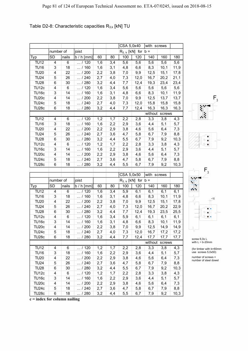
Page 81 of 124 of European Technical Assessment no. ETA-07/0245, issued on 2018-08-15
Table D2-8: Characteristic capacities R3,k [kN] TU
CSA 5,0x40 with screws
number of joist R3, k [kN] for b =
Typ SD nails b / h [mm] 60 80 100 120 140 160 180TU12 4 6 ... / 120 1,6 3,4 5,6 5,6 5,6 5,6 5,6TU16 3 18 ... / 160 1,6 3,1 4,8 6,6 8,3 10,1 11,9TU20 4 22 ... / 200 2,2 3,8 7,0 9,9 12,5 15,1 17,8TU24 5 26 ... / 240 2,7 4,0 7,3 12,0 16,7 20,2 21,1TU28 6 30 ... / 280 3,2 4,4 7,7 12,4 19,3 23,4 23,4
TU12c 4 6 ... / 120 1,6 3,4 5,6 5,6 5,6 5,6 5,6TU16c 3 14 ... / 160 1,6 3,1 4,8 6,6 8,3 10,1 11,9TU20c 4 14 ... / 200 2,2 3,8 7,0 9,9 12,5 13,7 13,7TU24c 5 18 ... / 240 2,7 4,0 7,3 12,0 15,8 15,8 15,8TU28c 6 18 ... / 280 3,2 4,4 7,7 12,4 16,3 16,3 16,3
without screwsTU12 4 6 ... / 120 1,2 1,7 2,2 2,8 3,3 3,8 4,3TU16 3 18 ... / 160 1,6 2,2 2,9 3,6 4,4 5,1 5,7TU20 4 22 ... / 200 2,2 2,9 3,8 4,6 5,6 6,4 7,3TU24 5 26 ... / 240 2,7 3,6 4,7 5,8 6,7 7,9 8,8TU28 6 30 ... / 280 3,2 4,4 5,5 6,7 7,9 9,2 10,3
TU12c 4 6 ... / 120 1,2 1,7 2,2 2,8 3,3 3,8 4,3TU16c 3 14 ... / 160 1,6 2,2 2,9 3,6 4,4 5,1 5,7TU20c 4 14 ... / 200 2,2 2,9 3,8 4,6 5,6 6,4 7,3TU24c 5 18 ... / 240 2,7 3,6 4,7 5,8 6,7 7,9 8,8TU28c 6 18 ... / 280 3,2 4,4 5,5 6,7 7,9 9,2 10,3
CSA 5,0x50 with screws
number of joist R3, k [kN] for b =
Typ SD nails b / h [mm] 60 80 100 120 140 160 180TU12 4 6 ... / 120 1,6 3,4 5,9 6,1 6,1 6,1 6,1TU16 3 18 ... / 160 1,6 3,1 4,8 6,6 8,3 10,1 11,9TU20 4 22 ... / 200 2,2 3,8 7,0 9,9 12,5 15,1 17,8TU24 5 26 ... / 240 2,7 4,0 7,3 12,0 16,7 20,2 22,9TU28 6 30 ... / 280 3,2 4,4 7,7 12,4 19,3 23,5 25,5
TU12c 4 6 ... / 120 1,6 3,4 5,9 6,1 6,1 6,1 6,1TU16c 3 14 ... / 160 1,6 3,1 4,8 6,6 8,3 10,1 11,9TU20c 4 14 ... / 200 2,2 3,8 7,0 9,9 12,5 14,9 14,9TU24c 5 18 ... / 240 2,7 4,0 7,3 12,0 16,7 17,2 17,2TU28c 6 18 ... / 280 3,2 4,4 7,7 12,4 17,7 17,7 17,7
without screwsTU12 4 6 ... / 120 1,2 1,7 2,2 2,8 3,3 3,8 4,3TU16 3 18 ... / 160 1,6 2,2 2,9 3,6 4,4 5,1 5,7TU20 4 22 ... / 200 2,2 2,9 3,8 4,6 5,6 6,4 7,3TU24 5 26 ... / 240 2,7 3,6 4,7 5,8 6,7 7,9 8,8TU28 6 30 ... / 280 3,2 4,4 5,5 6,7 7,9 9,2 10,3
TU12c 4 6 ... / 120 1,2 1,7 2,2 2,8 3,3 3,8 4,3TU16c 3 14 ... / 160 1,6 2,2 2,9 3,6 4,4 5,1 5,7TU20c 4 14 ... / 200 2,2 2,9 3,8 4,6 5,6 6,4 7,3TU24c 5 18 ... / 240 2,7 3,6 4,7 5,8 6,7 7,9 8,8TU28c 6 18 ... / 280 3,2 4,4 5,5 6,7 7,9 9,2 10,3
c = index for column nailing
F 3
screw 6,0x L
number of screws =
with L = b-20mm
number of steel dowel
(for timber with b=60mmuse screws 5,0x50)
F 3
~10

Page 82 of 124 of European Technical Assessment no. ETA-07/0245, issued on 2018-08-15
Table D2-9: Characteristic capacities R4k [kN] TU R4,k [kN] to beam / to column
number of
min. size of
joist
Typ SD nails b / h [mm]
TU12 4 6 …/120 4,1 4,9 5,7 8,4 8,4
TU16 3 18 …/160 6,1 7,5 8,9 11,4 11,4
TU20 4 22 …/200 8,2 9,8 11,5 16,2 16,2
TU24 5 26 …/240 10,2 12,1 14,1 21,0 21,0
TU28 6 30 …/280 11,8 14,4 16,7 25,4 25,8
TU12c 4 6 …/120 4,1 4,9 5,7 8,4 8,4
TU16c 3 14 …/160 5,3 6,4 7,5 11,4 11,4
TU20c 4 14 …/200 5,9 7,6 8,7 13,1 16,2
TU24c 5 18 …/240 7,4 9,8 11,3 16,8 21,0
TU28c 6 18 …/280 7,4 9,8 12,3 17,9 23,0
c = index for column nailing
CNA4,0x4
0
CNA4,0x5
0
CNA4,0x6
0
CSA
5,0x4
0
CSA
5,0x5
0
4F
4F

Page 83 of 124 of European Technical Assessment no. ETA-07/0245, issued on 2018-08-15
D3 Concealed joist hanger ETNM
Product Name
alternative names
France UK Danmark Germany
ETNM ETNM Figure D3-1: drawings Table D3-1: size specification ETNM
Model N°
Width W Height H Depth Angle (mm) degree Direction
ETNM135/130/2 70 135 130 90° ~ ETNM155/130/2 70 155 130 90° ~ ETNM185/130/2 70 185 130 90° ~ ETNM230/130/2 80 230 130 90° ~
Table D3-2 number of fastener
Hanger Type Header Fasteners Joist Fasteners
Ø4.0 connector nails Bolt M12
Concrete screw Dowels
Ø8 Dowels
Ø12 ETNM135/130/2 14 5 ~ 2 ETNM155/130/2 15 6 ~ 2 ETNM185/130/2 18 6 ~ 2 ETNM230/130/2 22 6 ~ 3
Table D3-3: Material specification
Material thickness Material Grades Coating specification
3 S 250 GD Z275
3 stainless steel as described

Page 84 of 124 of European Technical Assessment no. ETA-07/0245, issued on 2018-08-15
Table D3-4: Characteristic capacities ETNM R1,k Beam to beam
Joist width [mm]
Characteristic capacity R1,k [kN] with CNA4,0x50 connection beam to beam
ETNM135 ETNM155 ETNM185 ETNM230
60 11,7 14,4 17,1 26,2
80 12,2 15,0 17,8 27,0
100 13,1 16,0 18,9 28,6
120 14,2 17,2 20,4 30,6
140 15,4 18,6 22,0 32,8
160 16,6 20,0 23,8 35,1
Table D3-5: Characteristic capacities ETNM R1,k Beam to post
Joist width [mm]
Characteristic capacity R1,k [kN] with CNA4,0x50 connection beam to post
ETNM135 ETNM155 ETNM185 ETNM230
60 11,0 13,1 15,5 25,1
80 11,6 13,7 16,2 25,9
100 12,5 14,7 17,3 27,4
120 13,6 15,8 18,7 29,3
140 14,7 17,1 20,3 31,3
160 15,9 18,4 21,9 33,4
1F

Page 85 of 124 of European Technical Assessment no. ETA-07/0245, issued on 2018-08-15
Figure D3-2: Nail pattern ETNM
TYPE BEAM to BEAM BEAM to POST TYPE BEAM to BEAM BEAM to POST
135
14 nails 2 dowels Ø12
11 nails
2 dowels Ø12
185
18 nails 5 dowels Ø2
12 nails 5 dowels Ø12
155
15 nails 2 dowels Ø12
10 nails
2 dowels Ø12
230
22 nails 3 dowels Ø12
18 nails
3 dowels Ø12

Page 86 of 124 of European Technical Assessment no. ETA-07/0245, issued on 2018-08-15
D4 Concealed joist hanger BTCx
Product Name
alternative names
Branch 36
Branch 40
Branch 46
Branch 47
BTCx BTCx Figure D4-1: Dimension drawing of concealed joist hangers
A
BC t
C = 96
27 6 27
60
4040
A
Figure D4-2: Size specification
27 6 27
96
40
A
20n
x 40
20
3 108 20
131
ø13
A1A2
A3
ø1460
cut-out may be possible

Page 87 of 124 of European Technical Assessment no. ETA-07/0245, issued on 2018-08-15
Table D4-1: Size specification
all size in [mm] no of holes
Type A A1 A2 A3 B C t Ø14mm anchor
Ø13mm dowel
BTC120 120 128 96 3 2 3
BTC160 160 80 128 96 3 4 4
BTC200 200 120 128 96 3 4 5
BTC240 240 160 128 96 3 4 6
BTC280 280 100 100 128 96 3 6 7
BTC320 320 120 120 128 96 3 6 8
BTC360 360 140 140 128 96 3 6 9
BTC400 400 120 120 80 128 96 3 8 10
BTC440 440 120 120 120 128 96 3 8 11
BTC480 480 120 120 160 128 96 3 8 12
BTC520 520 160 160 120 128 96 3 8 13
BTC560 560 160 160 160 128 96 3 8 14
BTC600 600 160 160 200 128 96 3 8 15
Table D4-2: Material specification Material thickness
Material Grades
Coating stecification
3 S 250 GD Z275
3 stainless steel as destriped
For installation for fire justification, see clause B6
Table D4-3: Characteristic capacities R1.k and R2.k
The tables are based on a slope of 0° For other configurations the following modification are necessary:
for different slope β
β 0° 15° 30° 45° factor 1 0,95 0,9 0,85
only for less as 7 SD, for 7 or more SD no reducing is necessary
Characteristic capacity R1,k and R2.k [kN]
b 3 SD 4 SD 5 SD 6 SD 7 SD 8 SD 9 SD 10 SD 11 SD 12 SD80 11,5 18,5 26,7 35,8 45,6 56,0 66,8 77,9 89,1 100,5
100 12,7 20,4 29,4 39,4 50,1 61,4 73,1 85,1 97,2 109,5 120 14,2 22,8 32,7 43,8 55,6 68,1 80,9 94,0 107,3 120,7 140 15,8 25,3 36,4 48,6 61,7 75,5 89,6 104,1 118,7 133,4 160 17,2 27,8 40,3 53,8 68,3 83,4 99,0 114,8 130,9 147,0 180 17,2 27,8 40,3 54,3 69,4 85,5 102,2 119,5 133,3 147,0
b = min width [mm] of timber and length of the dowel
The topmost steel dowel in the cut out hole shall not be considered for R2.k For using steel dowels with a length of 60mm the values for steel dowel with 80mm may be multiplied by 0,95.

Page 88 of 124 of European Technical Assessment no. ETA-07/0245, issued on 2018-08-15
The necessary capacity of the bolts should be calculated as:
n
FR d
dlatbolt,1
,,
For the upper bolts additional:
d
FR d
daxbolt
4,14,1,,
With: Rbolt,lat,d design capacity of one anchor bolt for shear load, but max. 14,0 kN Rbolt,ax,d design capacity of one anchor bolt for tension load d height of the BTC -10mm [mm] n number of anchor bolts

Page 89 of 124 of European Technical Assessment no. ETA-07/0245, issued on 2018-08-15
Table D4-4: Characteristic capacities R3.k It is assumed that the force F3 is action at the top of the BTC. For a force F3 with a lower distance to the middle of the BTC, the same capacities may be to use
number of Joist min R3, k [kN] for b = .. [mm] without screws
Type SD bolts b / h [mm] 60 80 100 120 140 160 180
BTC120 3 2 ... / 160 2,6 2,9 3,5 4,0 4,5 5,2 5,3 BTC160 4 4 ... / 200 3,2 3,9 4,4 5,0 5,9 6,5 7,0 BTC200 5 4 ... / 240 4,0 4,9 5,5 6,3 7,2 7,8 8,8 BTC240 6 4 ... / 280 4,8 5,7 6,6 7,5 8,4 9,1 10,4 BTC280 7 6 ... / 320 5,6 6,5 7,6 8,7 9,6 10,4 11,9 BTC320 8 6 ... / 360 6,4 7,3 8,6 9,7 10,8 11,8 13,4 BTC360 9 6 ... / 400 7,2 8,1 9,5 10,8 12,0 13,2 14,9 BTC400 10 8 ... / 440 8,0 8,9 10,5 11,9 13,2 14,7 16,4 BTC440 11 8 ... / 480 8,8 9,7 11,4 13,0 14,4 16,1 17,8 BTC480 12 8 ... / 520 9,6 10,6 12,4 14,1 15,6 17,6 19,3 BTC520 12 8 ... / 560 10,4 11,4 13,3 15,1 16,8 19,1 20,8 BTC560 12 8 ... / 600 11,2 12,3 14,3 16,2 18,0 20,5 22,3 BTC600 12 8 ... / 640 12,0 13,2 15,2 17,3 19,2 22,0 23,8
SD = steel dowel Table D4-5: Characteristic capacities R3.k with screws for reinforcement It is assumed that the force F3 is in action at the top of the BTC. For a force F3 with a lower distance to the middle of the BTC, the same capacities may be to use
number of Joist min R3, k [kN] for b = .. [mm] with screws *
Type SD bolts b / h [mm] 60 80 100 120 140 160 180
BTC120 3 2 ... / 160 2,6 2,9 4,4 5,3 5,3 5,3 5,3
BTC160 4 4 ... / 200 3,2 4,3 6,6 7,0 7,0 7,0 7,0
BTC200 5 4 ... / 240 4,0 5,5 8,6 8,8 8,8 8,8 8,8
BTC240 6 4 ... / 280 4,8 6,3 8,8 10,6 10,6 10,6 10,6
BTC280 7 6 ... / 320 5,6 6,8 9,6 12,3 12,3 12,3 12,3 BTC320 8 6 ... / 360 6,4 7,5 10,1 14,1 14,1 14,1 14,1 BTC360 9 6 ... / 400 7,2 8,1 11,0 15,2 15,8 15,8 15,8 BTC400 10 8 ... / 440 8,0 8,9 11,0 15,2 17,6 17,6 17,6
BTC440 11 8 ... / 480 8,8 9,7 12,1 16,1 19,3 19,3 19,3
BTC480 12 8 ... / 520 9,6 10,6 12,8 17,1 21,1 21,1 21,1
BTC520 12 8 ... / 560 10,4 11,4 13,3 17,1 22,9 22,9 22,9
BTC560 12 8 ... / 600 11,2 12,3 14,3 17,6 24,6 24,6 24,6
BTC600 12 8 ... / 640 12,0 13,2 15,2 18,8 24,6 26,4 26,4 * See clause C.2
screw 6,0x L
number of screws =
with L = b-20mm
number of steel dowel
(for timber with b=60mmuse screws 5,0x50)
~10
F 3
Reinforcement with screws
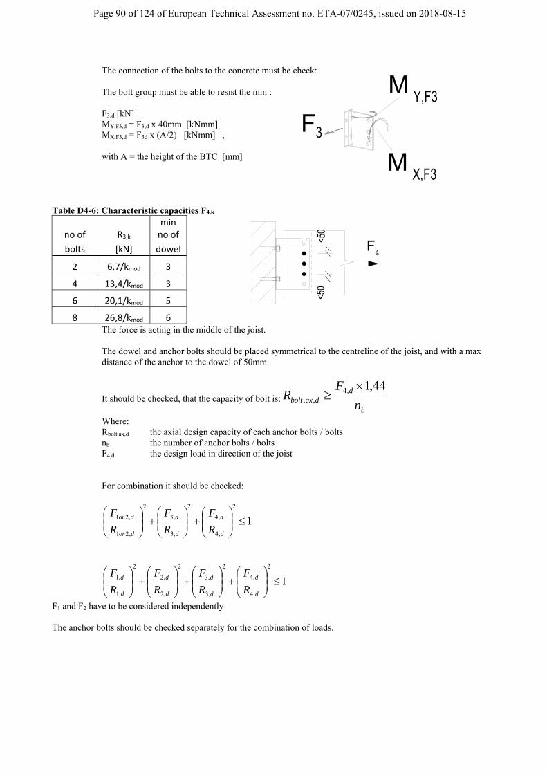
Page 90 of 124 of European Technical Assessment no. ETA-07/0245, issued on 2018-08-15
The connection of the bolts to the concrete must be check: The bolt group must be able to resist the min : F3,d [kN] MY,F3,d = F3,d x 40mm [kNmm] MX,F3,d = F3d x (A/2) [kNmm] ,
with A = the height of the BTC [mm]
Table D4-6: Characteristic capacities F4.k
no of R3,k min no of
bolts [kN] dowel
2 6,7/kmod 3
4 13,4/kmod 3
6 20,1/kmod 5
8 26,8/kmod 6 The force is acting in the middle of the joist. The dowel and anchor bolts should be placed symmetrical to the centreline of the joist, and with a max distance of the anchor to the dowel of 50mm.
It should be checked, that the capacity of bolt is:b
ddaxbolt n
FR
44,1,4,,
Where: Rbolt,ax,d the axial design capacity of each anchor bolts / bolts nb the number of anchor bolts / bolts F4,d the design load in direction of the joist For combination it should be checked:
1
2
,4
,4
2
,3
,3
2
,21
,21
d
d
d
d
dor
dor
R
F
R
F
R
F
1
2
,4
,4
2
,3
,3
2
,2
,2
2
,1
,1
d
d
d
d
d
d
d
d
R
F
R
F
R
F
R
F
F1 and F2 have to be considered independently The anchor bolts should be checked separately for the combination of loads.
X,F3
F 3
Y,F3M
M
<50
<50
F 4
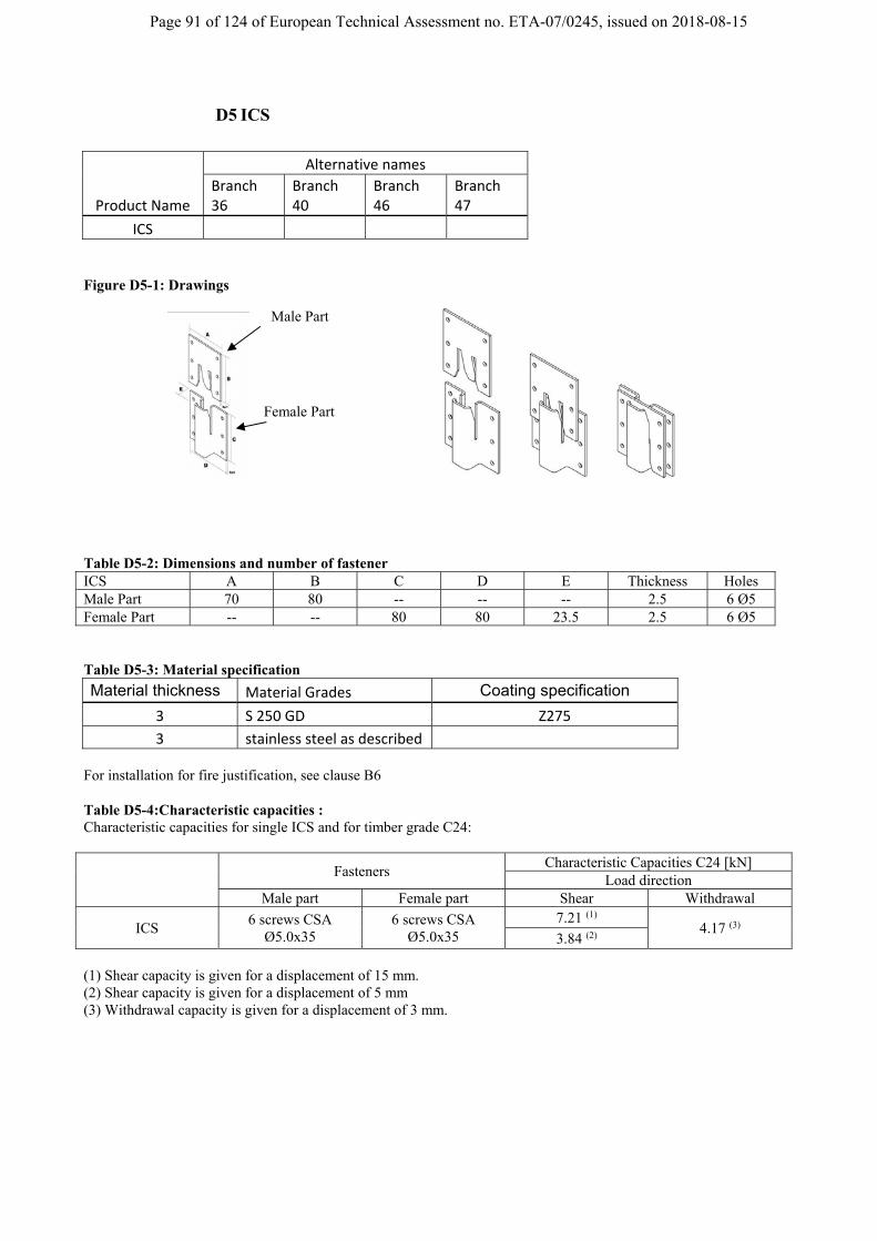
Page 91 of 124 of European Technical Assessment no. ETA-07/0245, issued on 2018-08-15
D5 ICS
Product Name
Alternative names
Branch 36
Branch 40
Branch 46
Branch 47
ICS
Figure D5-1: Drawings
Table D5-2: Dimensions and number of fastener ICS A B C D E Thickness Holes Male Part 70 80 -- -- -- 2.5 6 Ø5 Female Part -- -- 80 80 23.5 2.5 6 Ø5 Table D5-3: Material specification
Material thickness Material Grades Coating specification
3 S 250 GD Z275
3 stainless steel as described For installation for fire justification, see clause B6 Table D5-4:Characteristic capacities : Characteristic capacities for single ICS and for timber grade C24:
Fasteners
Characteristic Capacities C24 [kN] Load direction
Male part Female part Shear Withdrawal
ICS 6 screws CSA
Ø5.0x35 6 screws CSA
Ø5.0x35 7.21 (1)
4.17 (3) 3.84 (2)
(1) Shear capacity is given for a displacement of 15 mm. (2) Shear capacity is given for a displacement of 5 mm (3) Withdrawal capacity is given for a displacement of 3 mm.
Male Part
Female Part

Page 92 of 124 of European Technical Assessment no. ETA-07/0245, issued on 2018-08-15
Figure 1 : Timber element and position of ICS Figure 2: Lateral shear test
Shear
Withdrawal
Timber element 1
Timber element 2
F Lateral shear
Support of the 2 timber
Support of the timber
Position of the ICS
Timber element 1
Timber element 2
340 mm
340 mm
d1
d1
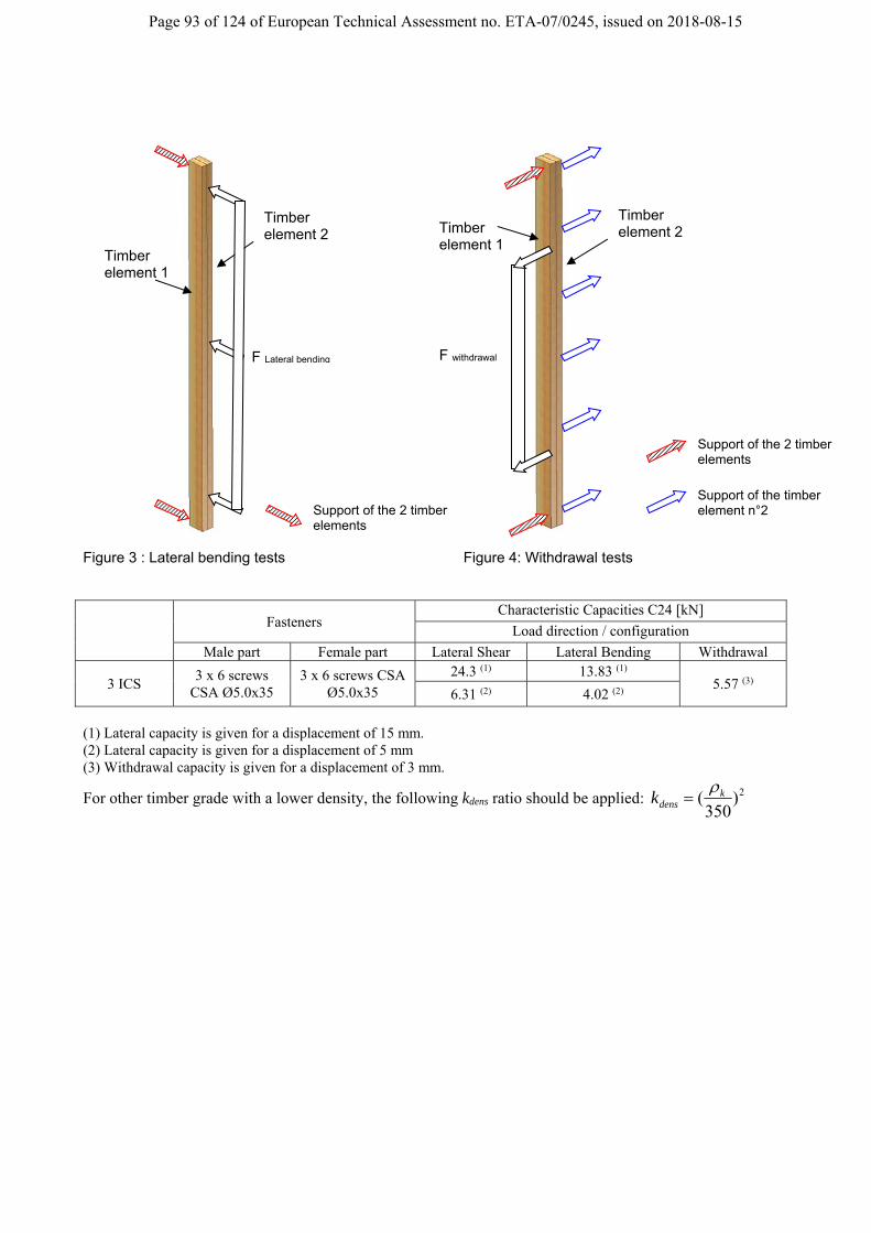
Page 93 of 124 of European Technical Assessment no. ETA-07/0245, issued on 2018-08-15
Figure 3 : Lateral bending tests Figure 4: Withdrawal tests
Fasteners
Characteristic Capacities C24 [kN]
Load direction / configuration
Male part Female part Lateral Shear Lateral Bending Withdrawal
3 ICS 3 x 6 screws
CSA Ø5.0x35 3 x 6 screws CSA
Ø5.0x35
24.3 (1) 13.83 (1) 5.57 (3)
6.31 (2) 4.02 (2)
(1) Lateral capacity is given for a displacement of 15 mm. (2) Lateral capacity is given for a displacement of 5 mm (3) Withdrawal capacity is given for a displacement of 3 mm.
For other timber grade with a lower density, the following kdens ratio should be applied: 2)350
( kdensk
Timber element 1
Timber element 2
F Lateral bending
Support of the 2 timber elements
Support of the 2 timber elements
Support of the timber element n°2
Timber element 1
Timber element 2
F withdrawal

Page 94 of 124 of European Technical Assessment no. ETA-07/0245, issued on 2018-08-15
D6 ETB
Product Name
alternative names
Branch 36
Branch 40
Branch 46
Branch 47
ETB
Figure D6-1: Drawings H2
B
B
H1
H3
t1
t2
ø5
H
female part
male part
23
0
195
121
90
166
ETB90 ETB120 ETB160 ETB190 ETB230
partial nailing or screwing for column connections
for fixing before screwing

Page 95 of 124 of European Technical Assessment no. ETA-07/0245, issued on 2018-08-15
Table D6-1: dimensions and number of fastener
Type sizes [mm] n n
H B H1 H2 H3 t1 / t2 Ø5,4 Ø5
ETB90 90 60 69 58 22,8 10 / 6 4 6
ETB120 121 60 95 85 27,8 10 / 6 6 9
ETB160 166 60 130 95 37,8 10 / 6 8 11
ETB190 195 75 165 138 31,8 10 / 6 11 19
ETB230 230 75 200 138 31,8 10 / 6 14 19 Table D6-2: Material specification Material thickness [mm]
Material Grades
Coating specification
6 Aluminium EN AW-6082 T6 according to EN 755-2
stainless steel as described
10 For installation for fire justification, see clause B6 Table D6-3:Characteristic capacities : ETB connectors - Force downward
klatH
kaxJ
k
Rn
Rn
R
,
,,9,0
,1 2min
nJ number of screws in the joist
nH number of screws or nails in the side grain of the header or column
Rlat,k Characteristic value of the load-carrying-capacity of a laterally loaded header/column nail or screw in single shear in a steel-to-timber connection with a thick steel plate according to EN 1995-1-1 or ETA 04/0013 in N
Rax,α,k characteristic axial load-carrying capacity of the screws in the joist according to EN 1995-1-1:2004:2008+A1:2008(E) in N, for the angle between the fiber of timber and the axis of the screw.

Page 96 of 124 of European Technical Assessment no. ETA-07/0245, issued on 2018-08-15
D7 EL
Product Name
alternative names
Branch 36
Branch 40
Branch 46
Branch 47
EL xx xx = size of EL
Figure D7-1: Drawings
8055 30 40 60 100
0
678297
120
10
b= b= b= b= b=
45°
35
9
45°
EL30 EL40 EL60 EL100
partial screwing
EL80 Table D7-1: dimensions and number of fastener
number of holes Ø5,4mm
type 45° top
EL30 3 1 EL40 6 1 EL60 9 2 EL80 12 3 EL100 15 4
Table D7-2: Material specification Material thickness
Material Grades
Coating specification
6 Aluminium EN AW-6082 T6 according to EN 755-2
stainless steel as described
10 For installation for fire justification, see clause B6

Page 97 of 124 of European Technical Assessment no. ETA-07/0245, issued on 2018-08-15
Table D7-3:Characteristic capacities :
mod
,90,90,
,90,90,
,,9,0
,1
278
38025
25,11
2
min
k
b
Afk
Af
A
bAfk
Rn
Refkcc
kyefckcc
kaxJ
k
klatH
d
k Rn
FR
,
,1
,4
3,0min
nJ number of screws in the joist
nH number of screws in the upper surface of the header
kc,90 Factor according to EN 1995-1-1:A1 taking into account the load configuration, the possibility of splitting and the degree of compressive deformation
fc,90,k Characteristic compressive strength perpendicular to the grain in N/mm²
Aef Effective contact area perpendicular to the grain in mm² according to EN 1995-1-1:A1
A Actual contact area perpendicular to the grain in mm²
b Width of the SIMPSON STRONG-TIE® EL hanger in mm
fy,k Aluminium minimum yield strength in N/mm²; fy,k = 250 N/mm²
F1,d design value of the joist support load perpendicular to the joist axis in N
Rax,α,k characteristic axial load-carrying capacity of the screws in the joist according to EN 1995-1-1:2004:2008+A1:2008(E) in N, for the angle between the fiber of timber and the axis of the screw.
Rlat,k Characteristic value of the load-carrying-capacity of a laterally loaded header nail or screw in N
type A [mm] Aef [mm] Aef /A
EL30 1350 3600 2,67
EL40 1800 4500 2,5
EL60 2700 5400 2
EL80 3600 6300 1,75
EL100 4500 7200 1,6
> 30mm
top plate of EL
header

Page 98 of 124 of European Technical Assessment no. ETA-07/0245, issued on 2018-08-15
The value Aef based on minimum distance of 30mm between the EL and the end of
header.
F2
R ax
uplift force
An uplift force may be adsorbed by an extra screw as shown above.
2)(,
,2Screwkax
k
RR
Rax,k(Screw) Characteristic axial load-carrying capacity of the extra screw as the min of threaded part
and pull through capacity of the head.

Page 99 of 124 of European Technical Assessment no. ETA-07/0245, issued on 2018-08-15
D8 ELS
Product Name
alternative names
Branch 36
Branch 40
Branch 46
Branch 47
ELS xx xx = Size of ELS
Figure D8-1: Drawings b= b= b= b= b=8030 40 60 100
45°
0
125140155
178
84x
10
101010 10
57
151
9
45°
10 20 10 20 20
108 93
partial screwing Table D8-1: dimensions and number of fastener
number of holes Ø5,4 Ø5,0
type 45° top ELS30 3 5 ELS40 6 8 ELS60 9 13 ELS80 12 15 ELS100 15 19
Table D8-2: Material specification Material thickness
Material Grades
Coating Specification
10 Aluminium EN AW-6082 T6
according to EN 755-2 stainless steel as described
For installation for fire justification, see clause B6 Table D8-3:Characteristic capacities :
klatH
kaxJ
k
Rn
Rn
R
,
,,9,0
,1 2min
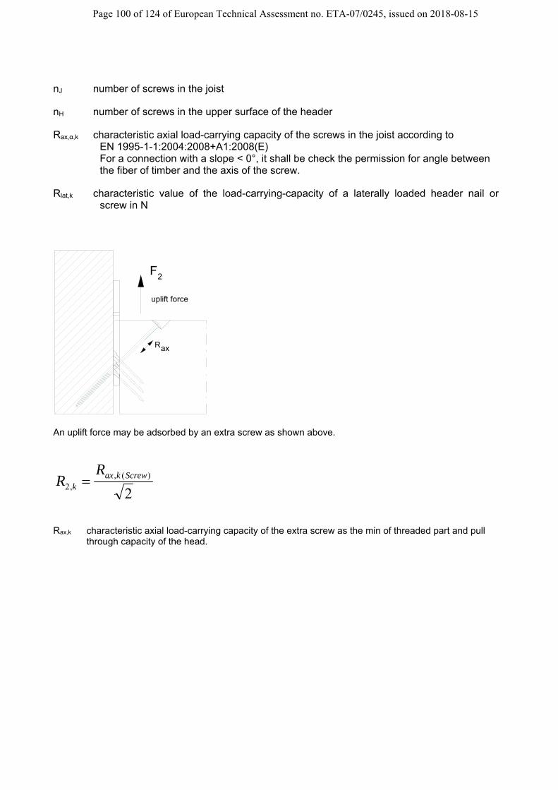
Page 100 of 124 of European Technical Assessment no. ETA-07/0245, issued on 2018-08-15
nJ number of screws in the joist
nH number of screws in the upper surface of the header
Rax,α,k characteristic axial load-carrying capacity of the screws in the joist according to EN 1995-1-1:2004:2008+A1:2008(E) For a connection with a slope < 0°, it shall be check the permission for angle between the fiber of timber and the axis of the screw.
Rlat,k characteristic value of the load-carrying-capacity of a laterally loaded header nail or screw in N
F2
R ax
uplift force
An uplift force may be adsorbed by an extra screw as shown above.
2)(,
,2Screwkax
k
RR
Rax,k characteristic axial load-carrying capacity of the extra screw as the min of threaded part and pull
through capacity of the head.

Page 101 of 124 of European Technical Assessment no. ETA-07/0245, issued on 2018-08-15
D9 CBH
Product Name
alternative names
Branch 36
Branch 40
Branch 46
Branch 47
CBH xxx / 2.5 xxx = size of CBH
Figure D9-1: Drawings
Table D9-1: Dimensions and number of fastener
Model [mm] Angle
Width W Height H Depth D Thickness degree Direction CBH105/2,5 40 105 100 2,5 90° ~ CBH150/2,5 60 150 113,5 2,5 90° ~ CBH180/2,5 60 180 113,5 2,5 90° ~ CBH220/2,5 60 220 113,5 2,5 90° ~
Model
Header Fasteners Joist Fasteners
nails or screws *
Bolts Anchors
Wood screws
Dowel Ø10 acc. To EN
14592
CBH105/2,5 8 2-Ø8 3
CBH150/2,5 14 2-Ø10 5
CBH180/2,5 16 2-Ø10 6
CBH220/2,5 22 2-Ø10 7
* According to ETA 04/0013 or according to EN14592 Washer for a wood/ rigid support connection. The minimum dimension has to be used:
Bolt Ø10 + Washer M10 (Øext = 20 – Øint = 11mm) Bolt Ø8 + Washer M8 (Øext = 16 – Øint = 8,5mm) for CBH105
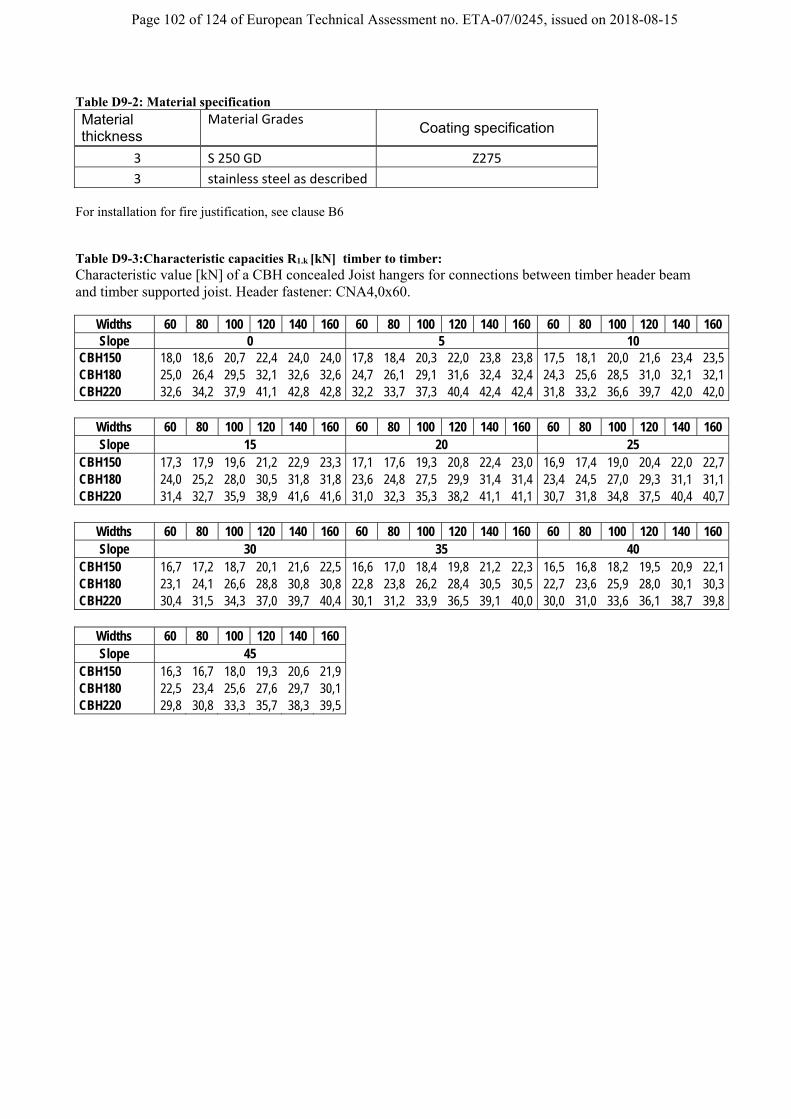
Page 102 of 124 of European Technical Assessment no. ETA-07/0245, issued on 2018-08-15
Table D9-2: Material specification Material thickness
Material Grades
Coating specification
3 S 250 GD Z275
3 stainless steel as described
For installation for fire justification, see clause B6 Table D9-3:Characteristic capacities R1.k [kN] timber to timber: Characteristic value [kN] of a CBH concealed Joist hangers for connections between timber header beam and timber supported joist. Header fastener: CNA4,0x60.
Widths 60 80 100 120 140 160 60 80 100 120 140 160 60 80 100 120 140 160 Slope 0 5 10
CBH150 18,0 18,6 20,7 22,4 24,0 24,0 17,8 18,4 20,3 22,0 23,8 23,8 17,5 18,1 20,0 21,6 23,4 23,5 CBH180 25,0 26,4 29,5 32,1 32,6 32,6 24,7 26,1 29,1 31,6 32,4 32,4 24,3 25,6 28,5 31,0 32,1 32,1 CBH220 32,6 34,2 37,9 41,1 42,8 42,8 32,2 33,7 37,3 40,4 42,4 42,4 31,8 33,2 36,6 39,7 42,0 42,0
Widths 60 80 100 120 140 160 60 80 100 120 140 160 60 80 100 120 140 160 Slope 15 20 25
CBH150 17,3 17,9 19,6 21,2 22,9 23,3 17,1 17,6 19,3 20,8 22,4 23,0 16,9 17,4 19,0 20,4 22,0 22,7 CBH180 24,0 25,2 28,0 30,5 31,8 31,8 23,6 24,8 27,5 29,9 31,4 31,4 23,4 24,5 27,0 29,3 31,1 31,1 CBH220 31,4 32,7 35,9 38,9 41,6 41,6 31,0 32,3 35,3 38,2 41,1 41,1 30,7 31,8 34,8 37,5 40,4 40,7
Widths 60 80 100 120 140 160 60 80 100 120 140 160 60 80 100 120 140 160 Slope 30 35 40
CBH150 16,7 17,2 18,7 20,1 21,6 22,5 16,6 17,0 18,4 19,8 21,2 22,3 16,5 16,8 18,2 19,5 20,9 22,1 CBH180 23,1 24,1 26,6 28,8 30,8 30,8 22,8 23,8 26,2 28,4 30,5 30,5 22,7 23,6 25,9 28,0 30,1 30,3 CBH220 30,4 31,5 34,3 37,0 39,7 40,4 30,1 31,2 33,9 36,5 39,1 40,0 30,0 31,0 33,6 36,1 38,7 39,8
Widths 60 80 100 120 140 160 Slope 45
CBH150 16,3 16,7 18,0 19,3 20,6 21,9 CBH180 22,5 23,4 25,6 27,6 29,7 30,1 CBH220 29,8 30,8 33,3 35,7 38,3 39,5

Page 103 of 124 of European Technical Assessment no. ETA-07/0245, issued on 2018-08-15
Table D9-4:Characteristic capacities R1.k [kN] timber to steel/concrete: Characteristic values [kN] for connection where the CBH joist hanger is bolted to a steel or reinforced concrete structural member and carrying a timber supported joist. 1. Dowel characteristic capacity Fk,dowels
Widths 60 80 100 120 140 160 60 80 100 120 140 160 60 80 100 120 140 160 Slope 0 5 10
CBH150 12,4 13,2 15,6 17,7 19,5 19,5 12,2 13,0 15,2 17,3 19,3 19,3 12,0 12,7 14,9 16,9 19,0 19,0 CBH180 19,3 21,1 25,2 28,8 29,7 29,7 18,9 20,7 24,6 28,1 29,2 29,2 18,5 20,2 23,9 27,4 28,8 28,8 CBH220 23,8 25,9 30,6 34,9 37,1 37,1 23,4 25,4 29,8 34,0 36,6 36,6 22,9 24,8 29,0 33,0 36,0 36,0
Widths 60 80 100 120 140 160 60 80 100 120 140 160 60 80 100 120 140 160 Slope 15 20 25
CBH150 11,7 12,4 14,5 16,4 18,4 18,7 11,5 12,1 14,1 15,9 17,9 18,3 11,3 11,8 13,7 15,4 17,3 18,0 CBH180 18,2 19,7 23,3 26,6 28,3 28,3 17,8 19,2 22,6 25,8 27,8 27,8 17,4 18,8 22,0 25,0 27,3 27,3 CBH220 22,4 24,2 28,2 32,1 35,3 35,3 22,0 23,6 27,4 31,1 34,7 34,7 21,5 23,0 26,7 30,2 34,0 34,1
Widths 60 80 100 120 140 160 60 80 100 120 140 160 60 80 100 120 140 160 Slope 30 35 40
CBH150 11,0 11,6 13,4 15,0 16,8 17,7 10,8 11,3 13,0 14,6 16,3 17,4 10,7 11,1 12,7 14,2 15,9 17,1 CBH180 17,0 18,3 21,4 24,3 26,8 26,8 16,7 17,9 20,9 23,6 26,4 26,4 16,4 17,6 20,4 23,1 26,0 26,0 CBH220 21,1 22,5 26,0 29,4 33,0 33,5 20,7 22,1 25,4 28,6 32,2 33,0 20,4 21,7 24,9 28,0 31,4 32,6
Widths 60 80 100 120 140 160 Slope 45
CBH150 10,5 10,9 12,5 13,9 15,5 16,9 CBH180 16,2 17,3 20,0 22,6 25,4 25,7 CBH220 20,1 21,3 24,4 27,4 30,8 32,2
2. Max characteristic capacity [kN] of the steel part Fk,steel Model Fk,steel
CBH150 15,9 CBH180 23,3 CBH220 26,1
3. Design capacity of the CBH – Fd,CBH
M
steelk
M
dowelsk
CBHd F
kF
F
,
mod,
, min

Page 104 of 124 of European Technical Assessment no. ETA-07/0245, issued on 2018-08-15
Table D9-5: Characteristic capacities timber to timber CBH105/2,5:
R1.k [kN] width of joist = length of steel dowel [mm]
45 50 60
CNA 4,0x40 8,9 8,9 9,2
CNA 4,0x50 9,6 9,6 9,9
CNA 4,0x60 min. of: 10,2 ;
11,2/kmod min. of: 10,3 ;
11,2/kmod min. of: 10,5 ;
11,2/kmod
CSA 5,0x35 min. of: 10,6 ;
11,2/kmod min. of: 10,6 ;
11,2/kmod min. of: 10,8 ;
11,2/kmod
CSA 5,0x40 min. of: 12 ; 11,2/kmod
min. of: 12 ; 11,2/kmod
min. of: 12,2 ; 11,2/kmod
CSA 5,0x50 min. of: 13,6 ;
11,2/kmod min. of: 13,7 ;
11,2/kmod min. of: 13,8 ;
11,2/kmod Table D9-6: Characteristic capacities timber to timber CBH105/2,5:
R2.k [kN] width of joist = length of steel dowel [mm]
45 50 60
CNA 4,0x40 6,4 6,5 6,6
CNA 4,0x50 7,1 7,2 7,3
CNA 4,0x60 7,7 7,8 7,9
CSA 5,0x35 8,4 8,5 8,6
CSA 5,0x40 9,8 9,8 9,9
CSA 5,0x50 min. of: 11,5 ;
11,2/kmod min. of: 11,5 ;
11,2/kmod min. of: 11,6 ;
11,2/kmod Table D9-7: Characteristic capacities timber to steel/concrete CBH105/2,5:
[kN] width of joist = length of steel
dowel [mm]
≥ 45mm
R1.k min. of: 13,6 ; 11,2/kmod
R2.k min. of: 11,5 ; 11,2/kmod

Page 105 of 124 of European Technical Assessment no. ETA-07/0245, issued on 2018-08-15
For sloped connection shall be use the following factors for the values from Table D9-5 to D9-7: for different slope β
β 0° 15° 30° 45° factor 1 0,95 0,9 0,85
slope
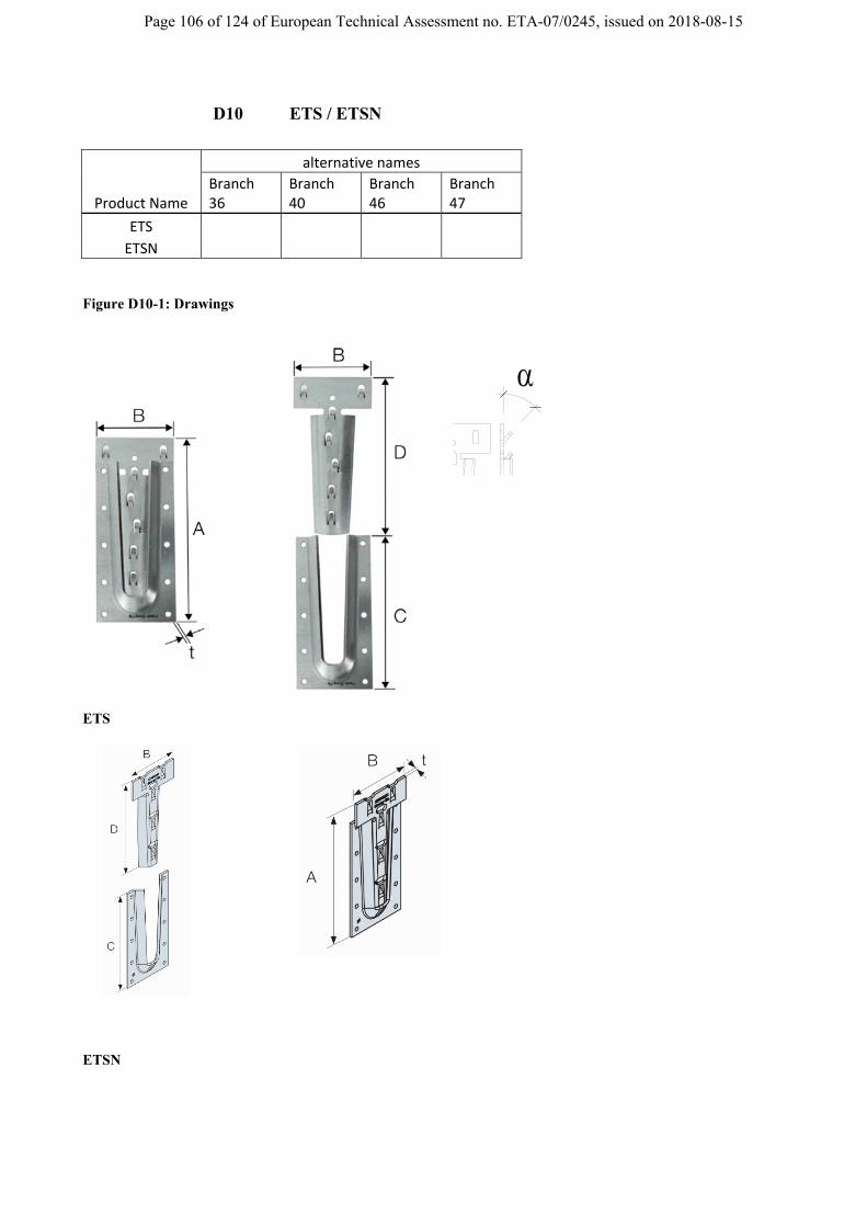
Page 106 of 124 of European Technical Assessment no. ETA-07/0245, issued on 2018-08-15
D10 ETS / ETSN
Product Name
alternative names
Branch 36
Branch 40
Branch 46
Branch 47
ETS
ETSN
Figure D10-1: Drawings
ETS
ETSN
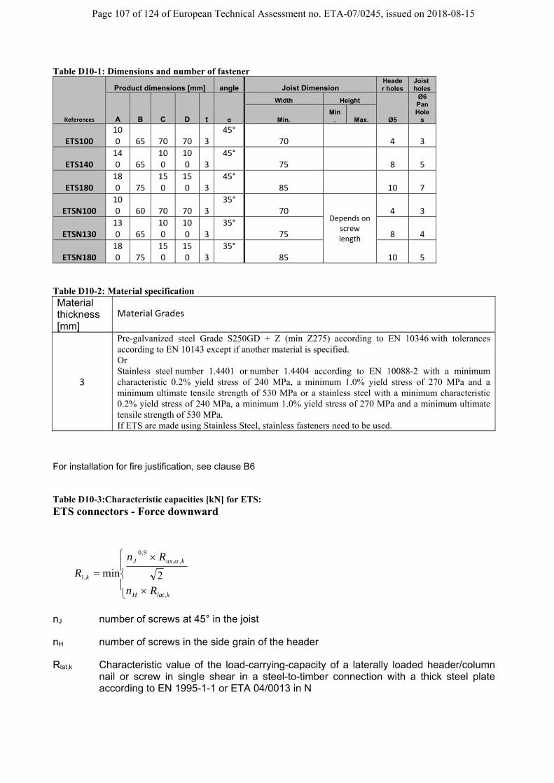
Page 107 of 124 of European Technical Assessment no. ETA-07/0245, issued on 2018-08-15
Table D10-1: Dimensions and number of fastener
References
Product dimensions [mm] angle Joist Dimension Header holes
Joist holes
A B C D t α
Width Height
Ø5
Ø6 Pan Hole
s Min. Min
. Max.
ETS100 100 65 70 70 3
45° 70
4 3
ETS140 140 65
100
100 3
45° 75
8 5
ETS180 180 75
150
150 3
45° 85
10 7
ETSN100 100 60 70 70 3
35° 70
Depends on screw length
4 3
ETSN130 130 65
100
100 3
35° 75 8 4
ETSN180 180 75
150
150 3
35° 85 10 5
Table D10-2: Material specification Material thickness [mm]
Material Grades
3
Pre-galvanized steel Grade S250GD + Z (min Z275) according to EN 10346 with tolerances according to EN 10143 except if another material is specified. Or Stainless steel number 1.4401 or number 1.4404 according to EN 10088-2 with a minimum characteristic 0.2% yield stress of 240 MPa, a minimum 1.0% yield stress of 270 MPa and a minimum ultimate tensile strength of 530 MPa or a stainless steel with a minimum characteristic 0.2% yield stress of 240 MPa, a minimum 1.0% yield stress of 270 MPa and a minimum ultimate tensile strength of 530 MPa. If ETS are made using Stainless Steel, stainless fasteners need to be used.
For installation for fire justification, see clause B6 Table D10-3:Characteristic capacities [kN] for ETS: ETS connectors - Force downward
klatH
kaxJ
k
Rn
Rn
R
,
,,9,0
,1 2min
nJ number of screws at 45° in the joist
nH number of screws in the side grain of the header
Rlat,k Characteristic value of the load-carrying-capacity of a laterally loaded header/column nail or screw in single shear in a steel-to-timber connection with a thick steel plate according to EN 1995-1-1 or ETA 04/0013 in N

Page 108 of 124 of European Technical Assessment no. ETA-07/0245, issued on 2018-08-15
Rax,α,k characteristic axial load-carrying capacity of the screws in the joist according to EN 1995-1-1:2004:2008+A1:2008(E) in N, for the angle between the fiber of timber and the axis of the screw.
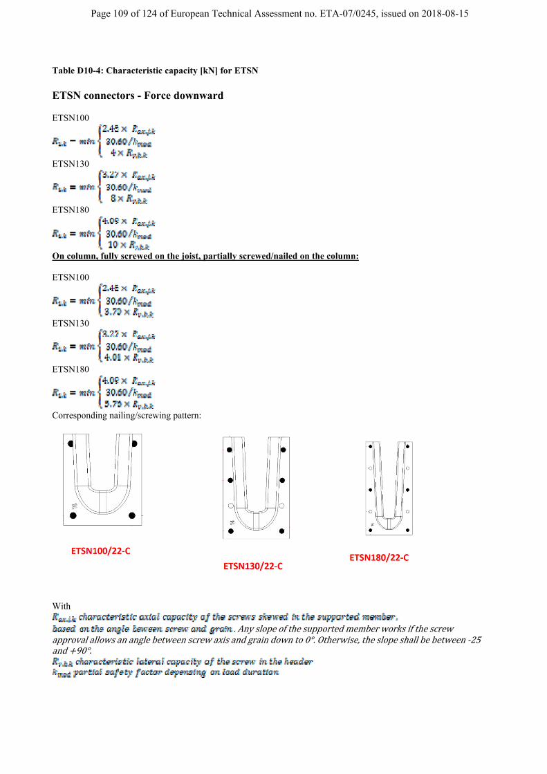
Page 109 of 124 of European Technical Assessment no. ETA-07/0245, issued on 2018-08-15
Table D10-4: Characteristic capacity [kN] for ETSN ETSN connectors - Force downward ETSN100
ETSN130
ETSN180
On column, fully screwed on the joist, partially screwed/nailed on the column: ETSN100
ETSN130
ETSN180
Corresponding nailing/screwing pattern:
With
.Anyslopeofthesupportedmemberworksifthescrew
approvalallowsananglebetweenscrewaxisandgraindownto0°.Otherwise,theslopeshallbebetween‐25and 90°.
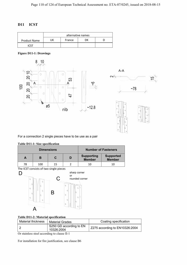
Page 110 of 124 of European Technical Assessment no. ETA-07/0245, issued on 2018-08-15
D11 ICST
Product Name
alternative names
UK France DK D
ICST Figure D11-1: Drawings
100
~78
~12.8
15
2
1020
2020
20
8 10
ø5
4753
~6A A
A-A
rib
For a connection 2 single pieces have to be use as a pair Table D11-1: Size specification
Dimensions Number of Fasteners
A B C D Supporting
Member Supported
Member
78 100 15 2 10 10
The ICST consists of two single pieces
A
B
CD sharp corner
or rounded corner
Table D11-2: Material specification
Material thickness Material Grades Coating specification
2 S250 GD according to EN 10326:2004
Z275 according to EN10326:2004
Or stainless steel according to clause II-1 For installation for fire justification, see clause B6

Page 111 of 124 of European Technical Assessment no. ETA-07/0245, issued on 2018-08-15
Figure D11-2: Nail/screw pattern Full nailing e.g. CNA 4,0xl nails , CSA5,0xl screws Table D11-3: Characteristic capacity [kN]
For one pair of ICST = two single pieces
characteristic capacities [kN] per connection (one pair)
R3,k R4,k
min of: 6,72*Rlat,k
min of: 4 x Rax,k
16,9/kmod 5,35/kmod
With Rlat,k = the lateral capacity of one single used fastener Rax,k = the axial capacity of one single used fastener For connection between timber elements (e.g. two wall elements) multiple ICST may be used. The two single pieces are to place on the “same” high (for example same distance “a” from the top as described below), by the mounting the elements are to fit into each other.
90
220
15
a
a
F3F4

Page 112 of 124 of European Technical Assessment no. ETA-07/0245, issued on 2018-08-15
D12 Janebo : JHHU, JHDU, JHGU, JHH, JHD, JHG
Product Name
alternative names
UK France DK D
JHHxx
JHD1‐xx JHDxx
JHGxx
JHHUxx ‐ ‐ ‐
JHDUxx ‐ ‐ ‐
JHGUxx ‐ ‐ ‐ ‐
Types with the “U” are for products with steel dowel for uplift; Drawings
B
h1
A
30
45
1912
6060
ø13
15
optionalsteel dowel
1249
95 2560
t1=10mm
Figure D12-1: Dimensioned drawings of JHHU
A
391239
C
8 38 44
B
70
t2
ø13
ø5
optional
15
t1
46
19 52 19
h2h1
25
steel dowel
Figure D12-2: Dimensioned drawings of JHDU

Page 113 of 124 of European Technical Assessment no. ETA-07/0245, issued on 2018-08-15
h2
25n
x 60
25
A
63 46 30
B
ø13
15
90steel dowel optional
t1=10mm
Figure D12-3: Dimensioned drawings for JHGU
14
25
ø13
option for the hook
JHH, JHD, JHGJHHU, JHDU, JHGU
steel dowelØ12mm foruplift
Figure D12-4: The hook for all types can be made in two different version, for an uplift force only the left one can be use.
Figure D12-5: example of use, for an uplift force (F2) the steel dowel as shown
in figure D12-4 on the left one has to be installed
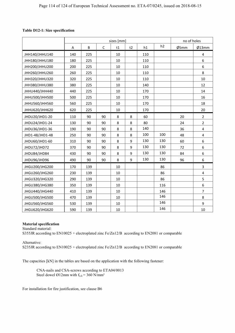
Page 114 of 124 of European Technical Assessment no. ETA-07/0245, issued on 2018-08-15
Table D12-1: Size specification
sizes [mm] no of holes
A B C t1 t2 h1 h2 Ø5mm Ø13mm
JHH140/JHHU140 140 225 10 110 4
JHH180/JHHU180 180 225 10 110 6
JHH200/JHHU200 200 225 10 110 6
JHH260/JHHU260 260 225 10 110 8
JHH320/JHHU320 320 225 10 110 10
JHH380/JHHU380 380 225 10 140 12
JHHU440/JHH440 440 225 10 170 14
JHHU500/JHH500 500 225 10 170 16
JHHU560/JHH560 560 225 10 170 18
JHHU620/JHH620 620 225 10 170 20
JHDU20/JHD1‐20 110 90 90 8 8 60 20 2
JHDU24/JHD1‐24 130 90 90 8 8 80 24 2
JHDU36/JHD1‐36 190 90 90 8 8 140 36 4
JHD1‐48/JHD1‐48 250 90 90 8 8 100 100 48 4
JHDU60/JHD1‐60 310 90 90 8 9 130 130 60 6
JHDU72/JHD72 370 90 90 8 9 130 130 72 6
JHDU84/JHD84 430 90 90 8 9 130 130 84 6
JHDU96/JHD96 490 90 90 8 9 130 130 96 6
JHGU200/JHG200 170 139 10 86 3
JHGU260/JHG260 230 139 10 86 4
JHGU320/JHG320 290 139 10 86 5
JHGU380/JHG380 350 139 10 116 6
JHGU440/JHG440 410 139 10 146 7
JHGU500/JHG500 470 139 10 146 8
JHGU560/JHG560 530 139 10 146 9
JHGU620/JHG620 590 139 10 146 10
Material specification Standard material: S355JR according to EN10025 + electroplated zinc Fe/Zn12/B according to EN2081 or comparable Alternative: S235JR according to EN10025 + electroplated zinc Fe/Zn12/B according to EN2081 or comparable The capacities [kN] in the tables are based on the application with the following fastener:
CNA-nails and CSA-screws according to ETA04/0013 Steel dowel Ø12mm with fu.k = 360 N/mm² For installation for fire justification, see clause B6

Page 115 of 124 of European Technical Assessment no. ETA-07/0245, issued on 2018-08-15
Characteristic capacities The checks below have to be made for both parts of a connection, eg: JHH with JHDU or JHHU with JHGU, the
weakest part is decisive.
R i.jt.k
i=load direction
j=type of JaneboH=JHHUD=JHDUG=JHGU
t = timber baseds = steel based
1 = download2 = uplift4 = axial
k = characteristicd = design
Or for uplift:
The factors k4.j.t and k4.j.s are given in the table for the respective values ηi .
Check:
Or for uplift (only for the types …U/xx):
1F2F
4F
1F2F
4FJHHU
JHGU
JHDU JHHU
bb
Mkjsi
kjtidji kkR
RR /;min modmod
......
Mkjtidjti kRR /mod....
Mkjsidjsi RR /....
djs
dsj R
F..1
.1..1
djt
dtj R
F..1
.1..1
jsdjs
djt
djt
d
dj
d kR
Fandk
R
Fand
R
F.4
..4
.4.4
..4
.4
..1
.1 1
djs
dsj R
F..2
.2..1
djt
dtj R
F..2
.2..1
jsdjs
djt
djt
d
dj
d kR
Fandk
R
Fand
R
F.4
..4
.4.4
..4
.4
..2
.2 1

Page 116 of 124 of European Technical Assessment no. ETA-07/0245, issued on 2018-08-15
For timber elements with a density ρk > 350 kg/m³, values can be increased as shown by the following table:
Ri.jt.k values may be increase:
to ρk [kg/m³]
from ρ 380 410 430
350 1,04 1,08 1,11
The values from the tables D12-2, D12-4 and D12-6 are based on a full nailing, using of all steel dowel holes.
standard connectionto use all nailholes / all holes for steel dowel
JHDUxx JHHUxx JHGUxx
JHD1-xx JHHxx JHGxxJHDxx
The steel based capacities for products, made from the material S235JG, have to be multiply with the factor 0,65 .
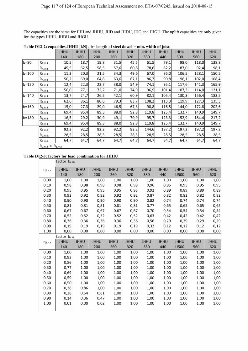
Page 117 of 124 of European Technical Assessment no. ETA-07/0245, issued on 2018-08-15
The capacities are the same for JHH and JHHU, JHD and JHDU, JHG and JHGU. The uplift capacities are only given for the types JHHU, JHDU and JHGU. Table D12-2: capacities JHHU [kN] , b= length of steel dowel = min. width of joist,
JHHU 140
JHHU 180
JHHU 200
JHHU 260
JHHU 320
JHHU 380
JHHU 440
JHHU 500
JHHU 560
JHHU 620
b=80 R1.Ht.k 10,5 18,7 19,8 31,5 45,5 61,5 79,1 98,0 118,0 138,8
R4.Ht.k 45,5 62,5 58,5 57,6 60,8 78,6 82,2 87,0 92,4 98,1
b=100 R1.Ht.k 11,3 20,3 21,5 34,3 49,6 67,0 86,0 106,5 128,1 150,5
R4.Ht.k 50,2 69,0 64,6 63,6 67,1 86,7 90,8 96,1 102,0 108,4
b=120 R1.Ht.k 12,4 22,3 23,7 38,0 54,9 74,1 95,1 117,6 141,3 165,9
R4.Ht.k 56,0 77,1 72,2 71,0 74,9 96,9 101,4 107,3 114,0 121,1
b=140 R1.Ht.k 13,7 24,7 26,2 42,1 60,9 82,1 105,4 130,3 156,4 183,5
R4.Ht.k 62,6 86,1 80,6 79,3 83,7 108,2 113,3 119,9 127,3 135,3
b=160 R1.Ht.k 15,0 27,3 29,0 46,5 67,3 90,8 116,5 144,0 172,8 202,6
R4.Ht.k 69,4 95,4 89,3 88,0 92,8 119,8 125,4 132,7 140,9 149,7
b=180 R1.Ht.k 16,5 29,2 30,9 49,1 70,9 95,7 123,3 152,9 184,4 217,2
R4.Ht.k 69,4 95,4 89,3 88,0 92,8 119,8 125,4 132,7 140,9 149,7
R1.Hs.k 92,2 92,2 92,2 92,2 92,2 144,6 197,2 197,2 197,2 197,2
R2.Hs.k 28,5 28,5 28,5 28,5 28,5 28,5 28,5 28,5 28,5 28,5
R4.Hs.k 64,7 64,7 64,7 64,7 64,7 64,7 64,7 64,7 64,7 64,7
R2.Ht.k = R1.Ht.k
Table D12-3: factors for load combination for JHHU
factor k4.Hs
η1.H.s JHHU 140
JHHU 180
JHHU 200
JHHU 260
JHHU 320
JHHU 380
JHHU 440
JHHU U500
JHHU 560
JHHU 620
0,00 1,00 1,00 1,00 1,00 1,00 1,00 1,00 1,00 1,00 1,00 0,10 0,98 0,98 0,98 0,98 0,98 0,96 0,95 0,95 0,95 0,95 0,20 0,95 0,95 0,95 0,95 0,95 0,92 0,89 0,89 0,89 0,89 0,30 0,92 0,92 0,92 0,92 0,92 0,87 0,82 0,82 0,82 0,82 0,40 0,90 0,90 0,90 0,90 0,90 0,82 0,74 0,74 0,74 0,74 0,50 0,81 0,81 0,81 0,81 0,81 0,77 0,65 0,65 0,65 0,65 0,60 0,67 0,67 0,67 0,67 0,67 0,70 0,54 0,54 0,54 0,54 0,70 0,52 0,52 0,52 0,52 0,52 0,63 0,42 0,42 0,42 0,42 0,80 0,36 0,36 0,36 0,36 0,36 0,56 0,29 0,29 0,29 0,29 0,90 0,19 0,19 0,19 0,19 0,19 0,32 0,12 0,12 0,12 0,12 1,00 0,00 0,00 0,00 0,00 0,00 0,00 0,00 0,00 0,00 0,00
factor k4.Ht η1.H.t JHHU
140 JHHU 180
JHHU 200
JHHU 260
JHHU 320
JHHU 380
JHHU 440
JHHU U500
JHHU 560
JHHU 620
0,00 1,00 1,00 1,00 1,00 1,00 1,00 1,00 1,00 1,00 1,00 0,10 0,93 1,00 1,00 1,00 1,00 1,00 1,00 1,00 1,00 1,00 0,20 0,86 1,00 1,00 1,00 1,00 1,00 1,00 1,00 1,00 1,00 0,30 0,77 1,00 1,00 1,00 1,00 1,00 1,00 1,00 1,00 1,00 0,40 0,69 1,00 1,00 1,00 1,00 1,00 1,00 1,00 1,00 1,00 0,50 0,59 1,00 1,00 1,00 1,00 1,00 1,00 1,00 1,00 1,00 0,60 0,50 1,00 1,00 1,00 1,00 1,00 1,00 1,00 1,00 1,00 0,70 0,38 0,86 1,00 1,00 1,00 1,00 1,00 1,00 1,00 1,00 0,80 0,28 0,64 0,81 1,00 1,00 1,00 1,00 1,00 1,00 1,00 0,90 0,14 0,36 0,47 1,00 1,00 1,00 1,00 1,00 1,00 1,00
1,00 0,01 0,00 0,02 1,00 1,00 1,00 1,00 1,00 1,00 1,00

Page 118 of 124 of European Technical Assessment no. ETA-07/0245, issued on 2018-08-15
Table D12-4: capacities JHDU [kN] R1.Dt.k JHDU
20 JHDU 24
JHDU 36
JHDU 48
JHDU 60
JHDU 72
JHDU 84
JHDU 96
CNA 4,0x40 16,8 23,1 44,2 66,3 88,5 110,3 131,9 153,3CNA 4,0x50 22,0 30,0 56,5 83,8 111,0 137,8 164,2 190,4CNA 4,0x60 26,7 36,2 66,6 97,6 128,3 158,4 188,2 217,7CSA 5,0x50 44,6 56,1 89,6 122,2 154,5 186,5 218,4 250,2CSA 5,0x80 62,8 77,8 121,7 164,7 207,3 249,8 292,1 334,3
R4.Dt.k JHDU 20
JHDU 24
JHDU 36
JHDU48 JHDU60 JHDU72 JHDU84 JHDU96
CNA 4,0x40 14,7 6,5 8,4 10,5 12,6 14,8 17,0 19,2CNA 4,0x50 19,6 8,7 11,2 14,0 16,8 19,7 22,6 25,5CNA 4,0x60 24,5 10,9 14,0 17,5 21,1 24,7 28,3 31,9CSA 5,0x50 64,0 28,5 36,7 45,7 55,0 64,4 73,9 83,4CSA 5,0x80 107,7 47,9 61,7 76,9 92,5 108,4 124,3 140,3
R2.Dt.k JHDU 20
JHDU 24
JHDU 36
JHDU 48
JHDU 60
JHDU 72
JHDU 84
JHDU 96
CNA 4,0x40 9,7 13,8 29,4 48,3 69,1 90,8 112,8 135,0CNA 4,0x50 12,8 18,2 38,4 62,5 88,6 115,6 142,9 170,2CNA 4,0x60 15,9 22,5 46,7 75,1 105,3 136,1 167,1 197,9CSA 5,0x50 33,8 44,9 79,4 113,6 147,1 180,1 212,8 245,2CSA 5,0x80 50,9 66,2 112,1 156,9 200,9 244,3 287,3 330,1
R1.Ds.k 44,0 68,9 134,0 134,0 150,8 150,8 150,8 150,8
R2.Ds.k 22,8 22,8 22,8 22,8 25,7 25,7 25,7 25,7
R4.Ds.k 16,4 17,1 24,0 31,2 38,5 41,5 41,5 41,5
Table D12-5: factors for load combination for JHDU
factor k4.Ds η1.D.s JHDU20 JHDU24 JHDU36 JHDU48 JHDU60 JHDU72 JHDU84 JHDU96
0,00 1,00 1,00 1,00 1,00 1,00 1,00 1,00 1,000,10 0,94 0,96 1,00 1,00 1,00 1,00 1,00 1,000,20 0,88 0,91 1,00 1,00 1,00 1,00 1,00 1,000,30 0,81 0,85 1,00 1,00 1,00 1,00 1,00 1,000,40 0,73 0,78 1,00 1,00 1,00 1,00 1,00 1,000,50 0,64 0,70 1,00 1,00 1,00 1,00 1,00 1,000,60 0,55 0,60 1,00 1,00 1,00 1,00 1,00 1,000,70 0,44 0,50 1,00 1,00 1,00 1,00 1,00 1,000,80 0,31 0,37 1,00 1,00 1,00 1,00 1,00 1,000,90 0,17 0,21 0,65 1,00 1,00 1,00 1,00 1,001,00 0,00 0,00 0,00 0,00 0,00 0,00 0,00 0,00
factor k4.Dt η1.D.t JHDU20 JHDU24 JHDU36 JHDU48 JHDU60 JHDU72 JHDU84 JHDU96
0,00 1,00 1,00 1,00 1,00 1,00 1,00 1,00 1,000,10 0,91 0,92 0,93 0,94 0,95 0,96 0,96 0,970,20 0,82 0,83 0,86 0,88 0,89 0,90 0,91 0,920,30 0,73 0,74 0,78 0,80 0,83 0,84 0,86 0,870,40 0,64 0,65 0,69 0,72 0,75 0,77 0,79 0,800,50 0,54 0,55 0,60 0,64 0,67 0,69 0,71 0,730,60 0,44 0,45 0,50 0,54 0,57 0,60 0,62 0,640,70 0,33 0,35 0,39 0,43 0,46 0,49 0,51 0,530,80 0,23 0,24 0,27 0,31 0,34 0,36 0,38 0,400,90 0,12 0,12 0,14 0,17 0,19 0,21 0,22 0,241,00 0,00 0,00 0,00 0,00 0,00 0,00 0,00 0,00
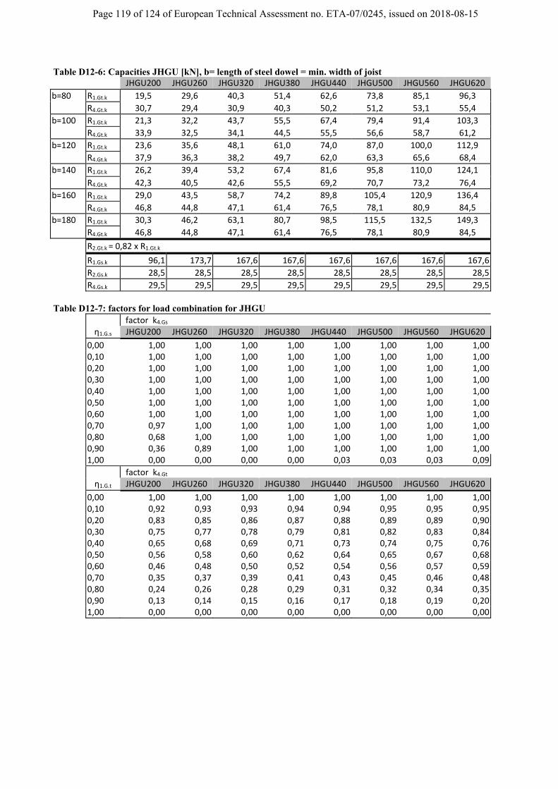
Page 119 of 124 of European Technical Assessment no. ETA-07/0245, issued on 2018-08-15
Table D12-6: Capacities JHGU [kN], b= length of steel dowel = min. width of joist JHGU200 JHGU260 JHGU320 JHGU380 JHGU440 JHGU500 JHGU560 JHGU620
b=80 R1.Gt.k 19,5 29,6 40,3 51,4 62,6 73,8 85,1 96,3
R4.Gt.k 30,7 29,4 30,9 40,3 50,2 51,2 53,1 55,4
b=100 R1.Gt.k 21,3 32,2 43,7 55,5 67,4 79,4 91,4 103,3
R4.Gt.k 33,9 32,5 34,1 44,5 55,5 56,6 58,7 61,2
b=120 R1.Gt.k 23,6 35,6 48,1 61,0 74,0 87,0 100,0 112,9
R4.Gt.k 37,9 36,3 38,2 49,7 62,0 63,3 65,6 68,4
b=140 R1.Gt.k 26,2 39,4 53,2 67,4 81,6 95,8 110,0 124,1
R4.Gt.k 42,3 40,5 42,6 55,5 69,2 70,7 73,2 76,4
b=160 R1.Gt.k 29,0 43,5 58,7 74,2 89,8 105,4 120,9 136,4
R4.Gt.k 46,8 44,8 47,1 61,4 76,5 78,1 80,9 84,5
b=180 R1.Gt.k 30,3 46,2 63,1 80,7 98,5 115,5 132,5 149,3
R4.Gt.k 46,8 44,8 47,1 61,4 76,5 78,1 80,9 84,5
R2.Gt.k = 0,82 x R1.Gt.k
R1.Gs.k 96,1 173,7 167,6 167,6 167,6 167,6 167,6 167,6
R2.Gs.k 28,5 28,5 28,5 28,5 28,5 28,5 28,5 28,5
R4.Gs.k 29,5 29,5 29,5 29,5 29,5 29,5 29,5 29,5
Table D12-7: factors for load combination for JHGU
factor k4.Gs η1.G.s JHGU200 JHGU260 JHGU320 JHGU380 JHGU440 JHGU500 JHGU560 JHGU620
0,00 1,00 1,00 1,00 1,00 1,00 1,00 1,00 1,00 0,10 1,00 1,00 1,00 1,00 1,00 1,00 1,00 1,00 0,20 1,00 1,00 1,00 1,00 1,00 1,00 1,00 1,00 0,30 1,00 1,00 1,00 1,00 1,00 1,00 1,00 1,00 0,40 1,00 1,00 1,00 1,00 1,00 1,00 1,00 1,00 0,50 1,00 1,00 1,00 1,00 1,00 1,00 1,00 1,00 0,60 1,00 1,00 1,00 1,00 1,00 1,00 1,00 1,00 0,70 0,97 1,00 1,00 1,00 1,00 1,00 1,00 1,00 0,80 0,68 1,00 1,00 1,00 1,00 1,00 1,00 1,00 0,90 0,36 0,89 1,00 1,00 1,00 1,00 1,00 1,00 1,00 0,00 0,00 0,00 0,00 0,03 0,03 0,03 0,09
factor k4.Gt η1.G.t JHGU200 JHGU260 JHGU320 JHGU380 JHGU440 JHGU500 JHGU560 JHGU620
0,00 1,00 1,00 1,00 1,00 1,00 1,00 1,00 1,00 0,10 0,92 0,93 0,93 0,94 0,94 0,95 0,95 0,95 0,20 0,83 0,85 0,86 0,87 0,88 0,89 0,89 0,90 0,30 0,75 0,77 0,78 0,79 0,81 0,82 0,83 0,84 0,40 0,65 0,68 0,69 0,71 0,73 0,74 0,75 0,76 0,50 0,56 0,58 0,60 0,62 0,64 0,65 0,67 0,68 0,60 0,46 0,48 0,50 0,52 0,54 0,56 0,57 0,59 0,70 0,35 0,37 0,39 0,41 0,43 0,45 0,46 0,48 0,80 0,24 0,26 0,28 0,29 0,31 0,32 0,34 0,35 0,90 0,13 0,14 0,15 0,16 0,17 0,18 0,19 0,20 1,00 0,00 0,00 0,00 0,00 0,00 0,00 0,00 0,00

Page 120 of 124 of European Technical Assessment no. ETA-07/0245, issued on 2018-08-15
Connection to Column: It´s possible to use the JHDU also for connection to column, in this case it is to use a nail pattern as shown following In this case, the capacity for connection to beam shall be multiply with the factors are given in the following both tables. Table D12-10: Column factors JHDU
factors for "column" nail pattern
for JHDU20 JHDU24 JHDU36 JHDU48 JHDU60 JHDU72 JHDU84 JHDU96
R1.Dt.k 0,61 0,51 0,56 0,50 0,53 0,50 0,52 0,50
R4.Dt.k 0,25 0,57 0,58 0,54 0,55 0,53 0,53 0,52
R2.Dt.k 0,62 0,54 0,56 0,51 0,53 0,50 0,52 0,50
Table Dx-11: Column factors JHHU
factors for "column" dowel pattern
for JHHU 140
JHHU 180
JHHU 200
JHHU 260
JHHU 320
JHHU 380
JHHU 440
JHHU 500
JHHU 560
JHHU 620
R1.Ht.k 0,47 0,51 0,51 0,54 0,56 0,57 0,59 0,61 0,62 0,64
R4.Ht.k 0,78 0,76 0,73 0,64 0,62 0,64 0,62 0,61 0,61 0,60
column / partial connection
star
t nai
ling
in
only
thes
e st
eel d
owel
JHDUxx JHHUxx
the
top
row
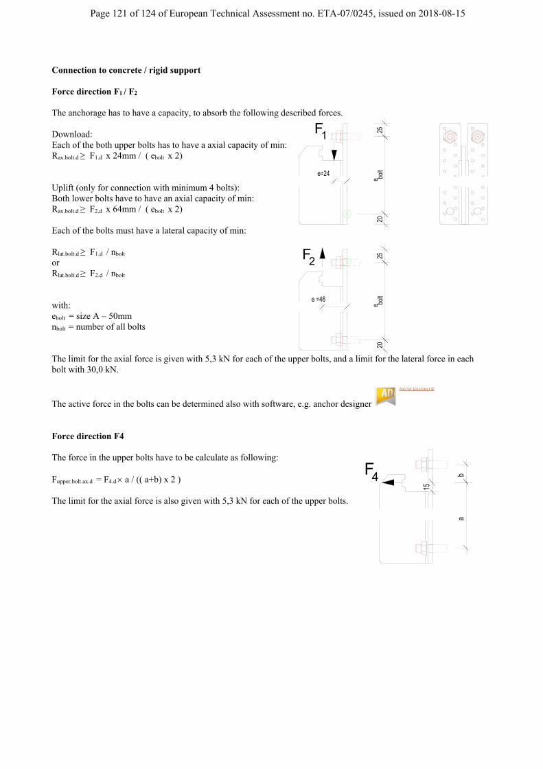
Page 121 of 124 of European Technical Assessment no. ETA-07/0245, issued on 2018-08-15
Connection to concrete / rigid support Force direction F1 / F2 The anchorage has to have a capacity, to absorb the following described forces. Download: Each of the both upper bolts has to have a axial capacity of min: Rax.bolt.d ≥ F1.d x 24mm / ( ebolt x 2) Uplift (only for connection with minimum 4 bolts): Both lower bolts have to have an axial capacity of min: Rax.bolt.d ≥ F2.d x 64mm / ( ebolt x 2) Each of the bolts must have a lateral capacity of min: Rlat.bolt.d ≥ F1.d / nbolt or Rlat.bolt.d ≥ F2.d / nbolt with: ebolt = size A – 50mm nbolt = number of all bolts The limit for the axial force is given with 5,3 kN for each of the upper bolts, and a limit for the lateral force in each bolt with 30,0 kN.
The active force in the bolts can be determined also with software, e.g. anchor designer Force direction F4 The force in the upper bolts have to be calculate as following: Fupper.bolt.ax.d = F4.d a / (( a+b) x 2 ) The limit for the axial force is also given with 5,3 kN for each of the upper bolts.
F1
e bolt
20
e=24
25
F2
bolt
e 20
e =46
25
4F ba
15

Page 122 of 124 of European Technical Assessment no. ETA-07/0245, issued on 2018-08-15
D13 ATFN
Product Name
UK France DK D
ATFN
Drawings
A A
B Ba a
bb
b-b
a-a
t1 t2 5.0
3.1
1.9
Ø10
Ø5
AA
male part
memberto the supported
member
female partto the supporting
Ø5
countersinkØ10mm
B
0,5xB
0,5xB
type
dimension [mm] number of holes
A B t1 t2 female part male part
ATFN55/110 55 110 5 5 8 11
ATFN55/150 55 150 5 5 11 15
ATFN55/190 55 190 5 5 14 21
ATFN75/150 75 150 5 5 17 22
ATFN75/190 75 190 5 5 21 28 Material specification Plates: S355MC according to EN10149 + Fe/Zn12/A or Fe/Zn12/B acc. to EN 2081 Pins: steel with a minimum yield strength of 580N/mm² a minimum tensile strength of 610 N/mm² and a minimum ultimate strain of 16%. The pins are connected with the plates by compression strain Connection to the supporting member: CNA-nails and CSA-screws according to ETA04/0013 Connection to the supported member: CSA-screws according to ETA04/0013 For installation for fire justification, see clause B6
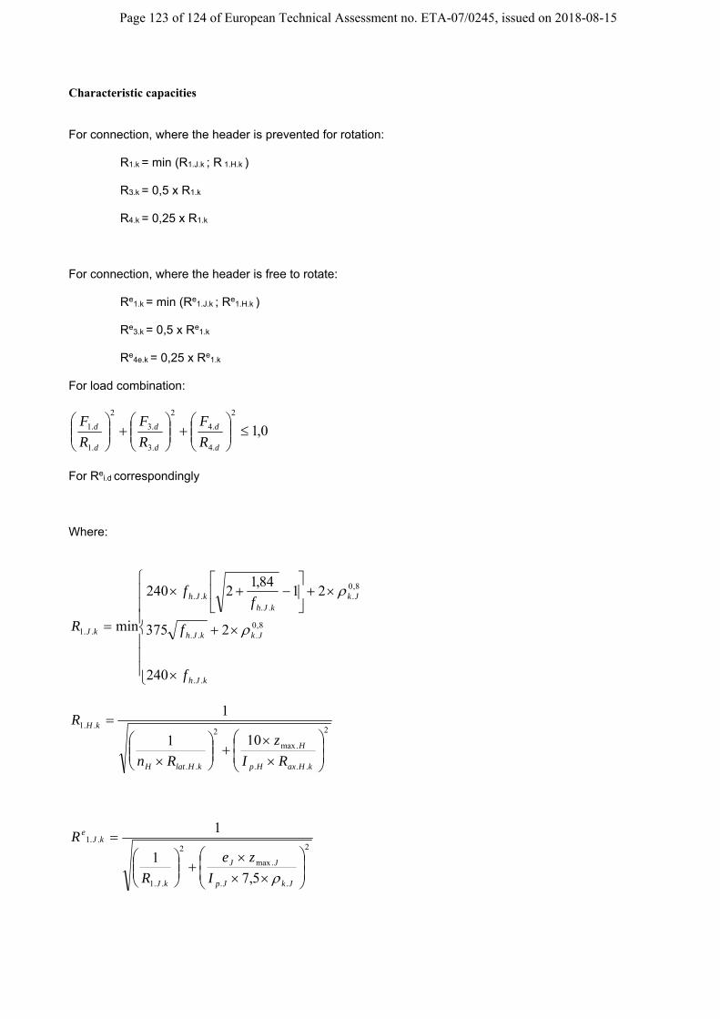
Page 123 of 124 of European Technical Assessment no. ETA-07/0245, issued on 2018-08-15
Characteristic capacities For connection, where the header is prevented for rotation:
R1.k = min (R1.J.k ; R 1.H.k ) R3.k = 0,5 x R1.k
R4.k = 0,25 x R1.k
For connection, where the header is free to rotate:
Re1.k = min (Re
1.J.k ; Re1.H.k )
Re
3.k = 0,5 x Re1.k
Re
4e.k = 0,25 x Re1.k
For load combination:
0,12
.4
.4
2
.3
.3
2
.1
.1
d
d
d
d
d
d
R
F
R
F
R
F
For Re
i.d correspondingly Where:
kJh
JkkJh
JkkJh
kJh
kJ
f
f
ff
R
..
8,0...
8,0.
....
..1
240
2375
2184,1
2240
min
2
...
.max
2
..
..1
101
1
kHaxHp
H
kHlatH
kH
RI
z
Rn
R
2
..
.max
2
..1
..1
5,7
1
1
JkJp
JJ
kJ
kJe
I
ze
R
R
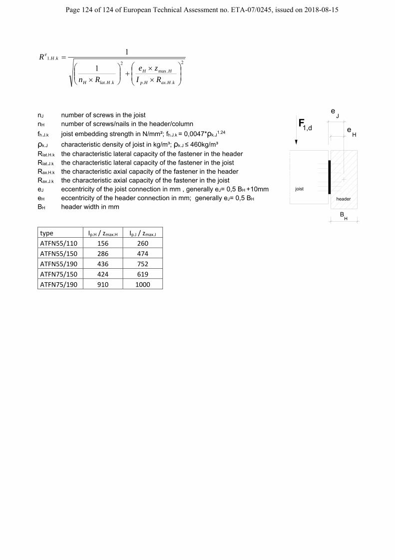
Page 124 of 124 of European Technical Assessment no. ETA-07/0245, issued on 2018-08-15
2
...
.max
2
..
..1
1
1
kHaxHp
HH
kHlatH
kHe
RI
ze
Rn
R
nJ number of screws in the joist nH number of screws/nails in the header/column
fh.J.k joist embedding strength in N/mm²; fh.J.k = 0,0047*ρk.J1.24
ρk.J characteristic density of joist in kg/m³; ρk.J ≤ 460kg/m³
Rlat.H.k the characteristic lateral capacity of the fastener in the header Rlat.J.k the characteristic lateral capacity of the fastener in the joist Rax.H.k the characteristic axial capacity of the fastener in the header Rax.J.k the characteristic axial capacity of the fastener in the joist eJ eccentricity of the joist connection in mm , generally eJ= 0,5 BH +10mm eH eccentricity of the header connection in mm; generally eJ= 0,5 BH
BH header width in mm
type Ip.H / zmax.H Ip.J / zmax.J
ATFN55/110 156 260
ATFN55/150 286 474
ATFN55/190 436 752
ATFN75/150 424 619
ATFN75/190 910 1000
HB
1,dFH
e
Je
header
joist