european new car assessment programme (euro ncap) sled ... · european new car assessment programme...
TRANSCRIPT

EUROPEAN NEW CAR ASSESSMENT PROGRAMME
(Euro NCAP)
SLED TEST PROCEDURE
FOR ASSESSING KNEE IMPACT AREAS
Version 2.7
June 2011

Version 2.7
June 2011
Copyright ©Euro NCAP - This work is the intellectual property of Euro NCAP. Permission is granted
for this material to be shared for non-commercial, educational purposes, provided that this copyright
statement appears on the reproduced materials and notice is given that the copying is by permission
of Euro NCAP. To disseminate otherwise or to republish requires written permission from Euro NCAP.

Version 2.7
June 2011
CONTENTS
1 INTRODUCTION ............................................................................................. 1
2 PREREQUISITES FOR KNEE MAPPING ...................................................... 2
3 HARDWARE SETUP ....................................................................................... 3
4 VALIDATION TEST ........................................................................................ 5
5 MAIN TEST PROGRAMME............................................................................ 7
6 PHOTOGRAPHIC RECORD ......................................................................... 11
7 DATA PROCESSING AND REPORTING .................................................... 12
8 KNEE AIRBAGS ............................................................................................ 12
9 INTERACTION WITH EURO NCAP ............................................................ 14
Appendix I ............................................................................................................... 15
Version 2.7
June 2011 1
1 INTRODUCTION
1.1 Where knee airbags are fitted to a car, it is not possible to carry out an
assessment of the knee contact zone in the normal way. Seat belt systems with
devices such as double pretensioners may also make the conventional
assessment, used by Euro NCAP, inappropriate. In other cases, the judgement
may be marginal and manufacturers may wish to check potentially hazardous
areas dynamically.
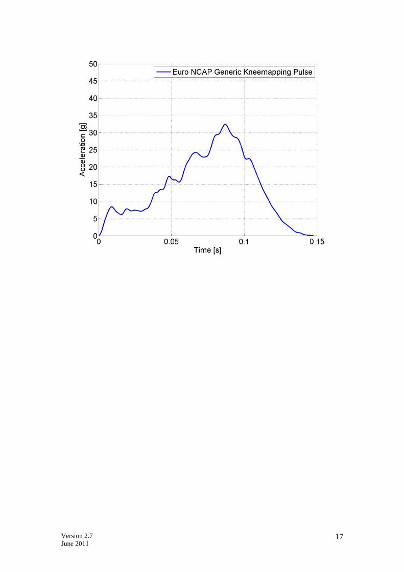
1.2 A generic pulse, determined from a representative batch of LHD and RHD
Euro NCAP ODB 64km/h tests, has been developed which can be used for any
knee mapping tests, either on driver or front passenger seats. The
corresponding acceleration and velocity change curves are attached in
Appendix I.
1.3 Where a manufacturer requests, Euro NCAP would accept a full series of knee
mapping tests to be performed using the pulse from a full scale 64km/h ODB
impact test instead of the generic pulse. ALL knee mapping tests must be done
using the same pulse whether it be the generic or vehicle pulse.
1.4 The manufacturer must demonstrate, for the areas in question, that femur loads
are less than 3.8kN and knee slider values are less than 6mm in order to avoid
knee modifiers. It should be noted that under normal circumstances, where the
variable load modifier is not applied, the concentrated load modifier is also not
applied.
1.5 The Euro NCAP assessment for knee modifiers considers occupants of
larger/smaller stature and weight than the 50th percentile Hybrid III used in
the Euro NCAP full vehicle test. The use of the 95th percentile dummy for
knee mapping ensures that a penetration deeper than that of the 50th percentile
is achieved. Therefore, the full depth of the assessment zone (50th percentile
penetration + 20mm) is covered by the test. Additionally, a 5th
percentile
female dummy may be required to asses those areas where the 95th
dummy leg
is unable to contact the hazards in the facia due to space restrictions.
1.6 In normal circumstances, the tests can be conducted prior to the full vehicle
test based on a Manufacturer’s assessment of the knee inspection zone.
However, there is the possibility that not all hazards are identified beforehand
and additional hazards may be highlighted for assessment in the inspection
report.
1.7 A validation test will be required by Euro NCAP if certain preconditions are
not met (see Section 4.2) to ensure that the test configuration is fully
representative of the full scale Euro NCAP test. Test houses should also be
familiar with the Euro NCAP testing protocols, which are frequently
referenced in this procedure. Details of the validation test requirements are in
Section 4. The components used in the testing must be of the same design,
specification, feature content and quality as those used in the official Euro
NCAP test.
Version 2.7
June 2011 2
2 PREREQUISITES FOR KNEE MAPPING
2.1 Vehicles that show large structural post test distortion are not eligible for knee
mapping. Any of the following post test conditions disqualify the vehicle from
knee mapping for any frontal occupants:
Femur loads >3.8kN in the full vehicle test (driver or passenger)
Knee Slider >6mm in the full vehicle test (driver or passenger)
Vehicles that qualify for the application of a structural modifiers i.e.
Integrity of the passenger compartment and/or footwell rupture
Vehicles with A-pillar displacements above 65mm (using the standard
Euro NCAP measurement)
● Where any frontal impact restraining devices, such as airbags &
pretensioners, deploy incorrectly, knee mapping data may not be accepted
for that occupant
2.2 It is the experience of the Euro NCAP secretariat that in cases where no
additional knee protection technology (e.g. dual pretensioning, collapsible
steering column design knee airbag or other suitable technology) is present,
the knee mapping has been shown to not be successful. However, the presence
of any particular technology to limit knee loads is not a pre-requisite for knee
mapping.
Version 2.7
June 2011 3
3 HARDWARE SETUP
3.1 Sled facility
3.1.1 An acceleration or deceleration based sled rig may be used. A “body in
white” buck of the car model being assessed shall be mounted on the sled. All
features which may influence knee impact protection must be installed in the
body in white.
3.2 Body preparation
3.2.1 The bodyshell should be mounted on the sled such that there will be no
permanent deformation of the body or its mounts, during the test programme.
This is necessary to help ensure good repeatability. The pitch angle of the
bodyshell should be set to 0 degrees, according to the manufacturer’s
specification.
3.2.2 The default yaw angle for the sled shall be 0 degrees. If the vehicle
manufacturer can identify the need for a yaw angle other than 0 degrees in
order to enable a stable contact with an identified hard point, this can be used
throughout the main test program. In no cases, would Euro NCAP allow the
yaw angle to be greater than 30 degrees.
3.2.3 Parts can be removed from the body in white, provided that there is no
question that their removal could influence the performance of the knee
impact area. Any structural or inertial support of the knee impact area should
be fully simulated. This would include the support given by the steering
column or loads transmitted through it.
3.2.4 The doors may be removed and the door aperture reinforced, to provide a clear
view for the cameras. All components added to the bodyshell should be to the
same specification as those used in the Euro NCAP frontal impact test. The
restraint system and any active devices should be replaced for each individual
test.
3.2.5 Intrusion may occur which does not directly affect the knee impact area but
which might provide additional support to structures supporting the knee
impact area. These should be identified in the Euro NCAP inspection. For the
sled tests, it may be acceptable for this type of intrusion to be simulated
statically e.g. wooden spacers.
3.3 Active restraints
3.3.1 Any active components of restraint systems should be identical to those used
in the Euro NCAP frontal impact test. However, it is acceptable for them to be
triggered remotely to match the Euro NCAP frontal impact test firing times
within ± 3ms. Where remote triggering is used, full details of the firing time,
proportion of charge used and any other relevant details should be supplied,
along with a comparison with relevant data from the Euro NCAP frontal
impact test.

Version 2.7
June 2011 4
Version 2.7
June 2011 5
4 VALIDATION TEST
4.1 Exemption from the validation test
4.1.1 Where all of the following test conditions are met by the driver (only) in the
nominated full scale test, a validation test is not required:
A-Pillar displacement below 35mm (using the standard Euro NCAP
measurement)
No significant seat, seat mounting or floor deformation that cannot be
replicated in the main test program.
Driver compressive femur loads below 1.0kN and passenger femur loads
below 2.0kN.
4.2 Sled Acceleration
4.2.1 It needs to be demonstrated that the sled test sufficiently replicates a 64km/h
ODB frontal impact of the subject vehicle. Therefore, the test can either be
conducted with the pulse of the official EuroNCAP crash test or a
representative development test. The vehicle used in the representative full
scale test should be similar to that intended for assessment in the official Euro
NCAP test in terms of engine, transmission and safety equipment. If the
specification of vehicle for the official test is not known, or a different hand of
drive is used, the manufacturer should provide data from a range of at least
three different vehicle specifications. The manufacturer may then choose the
representative test from the various examples provided and use it for the
validation.
4.2.2 The sled acceleration should be measured and compared with that measured,
at the base of the impact side B-pillar, in the representative full scale test
selected by the manufacturer.
4.2.3 The suitability of the correlation between the vehicle and sled pulses will be
checked according to the method detailed in Appendix I.
4.3 Steering column adjustment
4.3.1 The steering column shall be positioned the same as was the case in the Euro
NCAP frontal impact
4.4 Dummy and instrumentation
4.4.1 The validation test should be performed using the driver dummy only
regardless of whether driver or passenger knee mapping is to be performed. A
Hybrid III 50th percentile dummy shall be placed in the driver’s seat.
4.4.2 The dummy shall be instrumented to the same level or greater to that specified
for the Euro NCAP frontal impact test. Although the principal comparisons

Version 2.7
June 2011 6
will be made using knee and femur responses, this additional data can aid
understanding and explain any anomalies.
4.5 Seat position
4.5.1 The seat shall be positioned as in the Euro NCAP frontal impact test.
4.6 Dummy positions
4.6.1 The dummy shall be positioned as in the Euro NCAP frontal impact test, with
extra care taken to ensure that the knee impact areas will be comparable.
4.7 Performance criteria
4.7.1 The knee impact locations and loads should be comparable to those occurring
in the full scale test. To determine that this is so, the femur loads, the knee
slider displacements and the damage to the facia will all need to be compared.
Overall, the severity should be at least as severe as that in the representative
test.
4.7.2 In order to achieve the above, it might be necessary for the structural
deformation to be simulated statically or, where sled test technology allows,
dynamically. Furthermore, it might be necessary to introduce an alternative
yaw angle of the body shell, see Section 3.2.
Version 2.7
June 2011 7
5 MAIN TEST PROGRAMME
5.1 Sled Acceleration
5.1.1 The pulse performed on the sled facility should be at least as severe as the
generic or the representative 64km/h ODB test pulse, whichever is used, and
will be assessed according to the method detailed in Appendix I.
5.2 Steering column adjustment
5.2.1 The angular adjustment shall be positioned fully upwards with the axial
adjustment in the mid position.
5.3 Dummy and instrumentation
5.3.1 A 95th
percentile male Hybrid III dummy shall normally be used. However,
where it is not possible for the 95th
percentile knee to contact the hazard due to
its size, the 5th
percentile female shall be used. The specific dummy to be used
will be confirmed during the Euro NCAP inspection.
5.3.2 Whichever stature of dummy is to be used, it shall be equipped with at least
instrumentation to record femur axial force and knee slider displacement for
both legs. Shoulder belt loads shall also be recorded to demonstrate that the
pre-tensioning and load limiting characteristics of the restraint system are
similar to those in the Euro NCAP frontal impact test.
5.3.3 Additional instrumentation may be necessary in order to establish knee
penetration.
5.4 Driver seat position
5.4.1 For 95th
percentile dummies, adjust the vehicle seat according to the procedure
described in Section 6 of the Euro NCAP frontal crash test protocol.
5.4.2 Use the procedure described under chapter 7.1 or 7.2 respectively of the
frontal crash test protocol to determine the H-point.
5.4.3 Then move the seat rearward by 30mm. If the seat has no locking position
30mm reward choose the next notch forward.
5.4.4 In the event that the dummy is installed in the vehicle and there is insufficient
space between the knee and facia to position the knee in the desired area, then
the H-point should be moved rearward to allow correct position. Should this
be insufficient, the seat should be moved rearward until there is sufficient
space up to the 95th
percentile seating position.
Version 2.7
June 2011 8
5.4.5 For 5th
percentile dummies, the seat shall be positioned to the manufacturers
5th
percentile seating position in the fore/aft direction. All other seat
adjustments should be set to enable a stable knee contact with the target point.
5.5 Driver dummy positioning
5.5.1 The tolerances below detail the standard dummy position in the test
programme. If the point cannot be contacted by the knee after following the
steps detailed below, it may be necessary to deviate from one or all of these
values. In particular, the foot position must be such that the correct knee
impact area will be reached. Care should be taken that deviation from the
original position is as small as possible.
5.5.2 Initial H-point of the HIII 95th:
The HIII 95th dummy H-point shall be within 13mm horizontally of a point
30mm rearward of the H-point measured with the SAE J826 device during seat
adjustment
If the target H-point in the horizontal direction can not be achieved with the
given seat position move the seat one notch in the appropriate direction and try to
position the dummy again.
5.5.3 Pelvic angle:
The pelvic angle measurement gauge should read 22.5° ± 2.5° from the
horizontal.
5.5.4 Head:
The transverse instrumentation platform of the head shall be within 2.5° of
horizontal.
5.5.5 Arms + Hands:
For driver testing, place hands on the steering wheel in a similar fashion to that
of the Euro NCAP test. However, minor adjustments on the arm and hand
positions are allowed if this allows for better camera views of the knee impact
area.
For passenger testing, place the arms as in the Euro NCAP test setup.
5.5.6 Torso:
The torso should line up with the centre of the seat. However, the torso might
have to be twisted to one side to allow for the knees to strike the points indicated
in the Euro NCAP inspection. During twisting it is acceptable for the H-point
location to change.
5.5.7 Legs:
The legs should initially be positioned according to the Euro NCAP frontal test
protocol, but then their position shall be modified laterally so that the main load
bearing knee will come into contact with the potential hard-point as indicated in
the inspection report. The other knee shall be aimed at an area where it would be
expected to receive experience little or no loading. Frequently, this would be
achieved by positioning it laterally where it has the greatest spacing from the
Version 2.7
June 2011 9
facia. The lateral position of the knees can be achieved with a variation of the
knee spread and/or a twist of the torso.
5.5.8 Feet:
The feet should be placed as flat as possible on the toe board parallel to the
centreline of the vehicle. If either of the feet comes into contact with a footrest or
a wheel arch, place the foot fully onto that rest. It is permissible to adjust the foot
position to ensure that the correct knee impact location can be obtained. In order
to ensure a stable knee contact, it may also be necessary to prevent the relevant
foot from moving forwards in the footwell.
5.6 Passenger dummy positioning
5.6.1 The minimum knee penetration required for all of the passenger femur load
tests within main test programme is based on the limit of the inspection zone.
This will be detailed in the inspection report and be based upon the penetration
of the passenger knee obtained in the official Euro NCAP test including an
additional 20mm.
5.6.2 The passenger dummy positioning procedure will follow the procedure
described in Sections 5.4 & 5.5. However, if this seating/dummy position does
not achieve a minimum knee penetration equal to that of the limit of the
inspection zone, the seat and dummy should be adjusted so that this limit is
reached by the knee throughout the main test programme.
5.6.3 The penetration of the passenger knee will be established using high speed
video footage and/or pelvic displacement calculations. Alternative
measurement methods for establishing pelvic displacement will also be
accepted which can be shown to be of equal accuracy as using pelvis
acceleration to establish knee penetration. If the position of the dummy is
limited by the knees contacting the hazard and/or the amount of available seat
travel, that most forward position should be used.
5.6.4 Situations were potential hazards for knee slider are highlighted are treated
equivalent to test for potential knee hazards. The dummy positioning
procedure will follow the procedure described in Sections 5.4 & 5.5. However,
if this seating/dummy position does not achieve a minimum knee displacement
equal to that of the limit of the inspection zone (20mm), the seat and dummy
should be adjusted so that this limit is reached. If knee slider is a concern it
needs to be ensured that there is stable contact between the tibia and potential
hazard. It may be necessary to make small adjustments to the angel of the
Tibia to ensure contact with the correct location.
5.7 Ensuring a stable knee contact to the potential hard point
5.7.1 In order for a knee mapping sled test to be valid, it needs to be ensured that the
main load bearing knee remains in stable contact with the potential hard point
during the impact sequence. If the knee is deflected, the test will not be
accepted as a valid measure of the potential hazard. It is important that the

Version 2.7
June 2011 10
other knee is loaded as little as possible by either not contacting the facia or
impacting the least supported area of the facia.
5.7.2 In order to ensure this it is allowable for the knee spread to be artificially fixed
(i.e. by the application of structural foam or similar, between the legs).
Furthermore, it might be necessary to prevent the feet from moving forward
during crash in order to prevent a dynamic drop of the knee during the impact
sequence.
5.7.3 If a stable contact can not be achieved with artificial knee spreading alone it is
allowable to use an appropriate yaw angle of the sled other than 0 degrees to
assess an individual hard point.
5.7.4 In any case, it is essential to confirm the stable knee contact with the use of
appropriate high speed camera footage.
5.8 Dummy painting
5.8.1 In the absence of acceptable camera evidence, paint or other suitable
alternatives may be used in order to identify that the correct point has been
contacted.
5.9 Performance criteria
5.9.1 In the Euro NCAP inspection, the potential hazards will be identified and it
will be necessary for all of them to be fully explored in the test programme.
5.9.2 The performance criteria used for the assessment will be femur forces below
3.8kN and the knee slider responses shall be less than 6mm. No adjustment to
the performance criteria is made for any change in dummy size.

Version 2.7
June 2011 11
6 PHOTOGRAPHIC RECORD
6.1 High speed film
6.1.1 High speed film is required for ALL knee mapping testing including the
validation test.
6.1.2 Sled mounted high speed cameras should be used to record the whole of the
relevant scene. This would include the seat, seat belt system, facia, steering
column, door aperture and dummy trajectory from both left and right sides. It
should record the knee impact location and provide verification that the knee
was not deflected from the chosen location and that the feet remained stable
on the toe board. This should include a camera view showing the knees and a
camera view that shows the feet for the complete impact sequence. The high
speed camera frame rate should be of the order of 1000 frames per second.
6.2 Still photography
6.2.1 In order for any knee mapping results to be accepted by Euro NCAP, it is
essential that adequate photographic evidence of the test is provided by the
manufacturer.
6.2.2 Pre and post test still photography is required to clearly show the sled set-up
and BIW construction. Still photographs should show the fixings of the body
in white to the sled, in particular the steering column and facia mounting and
the appropriate body reinforcements before and after the series of tests.
Additionally, any structures added to simulate intrusion which could support
the knee impact area should also be recorded.
6.2.3 The structures present in the facia should be clearly visible to provide
evidence that the sled set-up is representative of a production vehicle and that
all required components have been included.
6.2.4 It is essential that the position of the dummy and particularly its knees should
be clearly shown, along with a photographic record of the paint applied to the
knees. After each test, a record should be made of the knee contact area, any
paint transfer marks, and any damage to any of the knee impact area
components.
6.2.5 Any broken, damaged or fatigued components should also be fully recorded
using photographs. In some cases it will be necessary to remove these from the
facia after the tests in order to provide the best view.
6.3 Insufficient high speed or still photography could result in the knee mapping
not being accepted by the Euro NCAP Secretariat.

Version 2.7
June 2011 12
7 DATA PROCESSING AND REPORTING
7.1 Data processing
7.1.1 The test data should be sampled and filtered as specified in the Euro NCAP
frontal impact test protocol.
7.2 Reporting
7.2.1 Full information about the test set up should be supplied to Euro NCAP. This
should include details of any work that has been done to compensate for
supportive intrusion, how the steering column lower mass and attachments
have been simulated and any special arrangements related to dummy
positioning. Anything which could influence the assessment should be fully
reported.
7.2.2 For the validation test, a comparison should be provided to satisfy Euro NCAP
that the test set up and pulse is suitable for the assessment work.
7.2.3 For the main test programme, the locations being investigated should be
detailed and the outcome from each test should be given. In both cases, full
data should be supplied, including graphical plots. A full explanation and
comparative analysis should be supplied.
8 KNEE AIRBAGS
8.1 The test set-up and the assessment criteria described above are also applicable
for vehicles with knee airbags. Knee mapping test data must be provided in
order to avoid the variable load modifier. However, it is assumed that a
properly deploying knee airbag substitutes the function of foam and load
spreader in order to avoid the concentrated load modifier. The presence of a
knee airbag will not automatically lead to the removal of the concentrated load
modifier; knee mapping data will be required to prove the effectiveness of the
system. The presence of a knee airbag will not automatically lead to the
removal of the concentrated load modifier; knee mapping data will be required
to prove the effectiveness of the system.
8.2 Where the measured femur force is less than 3.8kN and the knee slider
displacement is below 6mm, the variable contact and concentrated load
modifiers will not be applied provided that, there is no bottoming out of the
knee airbag.
8.3 It must be clear that there is no risk associated with the presence of the airbag
module or its support structures.
8.4 Where a knee airbag does bottom out in the official ODB test, an additional
sled test with the 50% percentile dummy in the ODB test seating position
(setup as of validation test) is required with an airbag deployment time 10ms

Version 2.7
June 2011 13
later than that used in the official ODB test. Where the femur loads or/and
knee slider displacement exceed the acceptance criteria in Section 8.2, the
variable load modifier will be applied.
8.4.1 Bottoming out of the knee airbag will be identified from the femur traces
using sharp increases in femur load of at least 1kN in 5ms, and an
accompanying increase in pelvis acceleration. There may also be physical
damage to any underlying structures and evidence from high speed film.
8.4.2 If a knee airbag is deemed to have bottomed out in any of the tests and the
femur loads and/or knee slider results exceed the acceptance criteria in Section
8.2, the variable load modifier will be applied.

Version 2.7
June 2011 14
9 INTERACTION WITH EURO NCAP
9.1 Any manufacturer who intends to present knee mapping test results to Euro
NCAP is required to advise the Secretariat when completing the vehicle
matrix.
9.2 Where additional Euro NCAP inspector or Secretariat time or resources are
required to consider knee mapping data or to hold additional meetings, the
costs will have to be funded by the manufacturer.

Version 2.7
June 2011 15
Appendix I
The pulse performed on the sled facility should be close to or more severe as the
generic test pulse. To validate this point, the following process should be used:
Change the orientation to have sled pulse and generic pulse in globally positive
values
Calculate by integration the Delta V from generic pulse DV1(t), setting the initial
velocity to 0
Calculate by integration the Delta V from sled test DV2(t), setting the initial
velocity to 0
Calculate the difference DV = DV1 – DV2
Calculate by integration of DV1 the X displacement from generic pulse DX1(t),
setting the initial value to 0
Calculate by integration of DV2 the X displacement from sled test DX2(t), setting
the initial value to 0
Calculate the difference DX(t) = DX1(t) – DX2(t)
Calculate DX at 120 ms
Requirement #1:
o If all the DV values up to 120 ms are in the zone as shown below,
requirement #1 is OK – check requirement #2
o If some DV values up to 120 ms are outside the zone, requirement #1 is not
OK,
sled test is less severe than the generic or ODB test
pulse and cannot be accepted
Sample pulse showing a sled test that cannot be accepted as parts of DV are outside
the acceptable zone
Accepted
DV = DV(Generic or Vehicle Pulse) – DV(Sled) test)
Not Accepted
Not Accepted
Version 2.7
June 2011 16
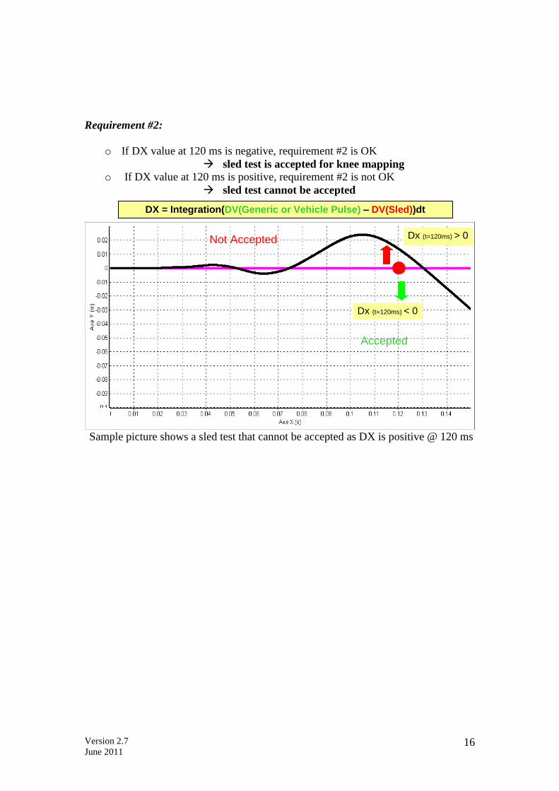
Requirement #2:
o If DX value at 120 ms is negative, requirement #2 is OK
sled test is accepted for knee mapping
o If DX value at 120 ms is positive, requirement #2 is not OK
sled test cannot be accepted
Sample picture shows a sled test that cannot be accepted as DX is positive @ 120 ms
DX = Integration(DV(Generic or Vehicle Pulse) – DV(Sled))dt
Accepted
Not Accepted
Dx (t=120ms) < 0
Dx (t=120ms) > 0
Version 2.7
June 2011 17