european electronic controls catalogue e 05 2000 va-7150
TRANSCRIPT
European Electronic Controls CatalogueSection E
Product Bulletin VA-7150Issue Date 05 2000
© 2000 Johnson Controls, Inc. E 14Order No. 10.736 E
VA-7150Electric Valve Actuator
Introduction
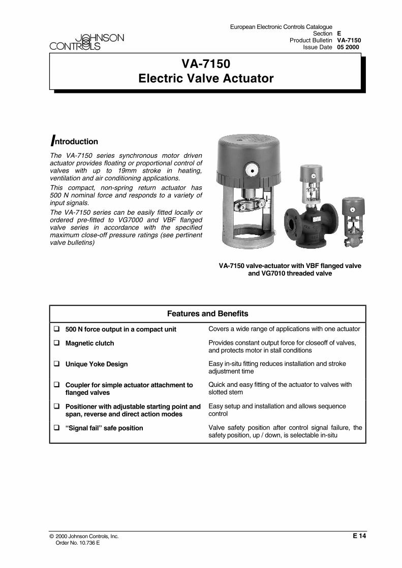
The VA-7150 series synchronous motor drivenactuator provides floating or proportional control ofvalves with up to 19mm stroke in heating,ventilation and air conditioning applications.This compact, non-spring return actuator has500 N nominal force and responds to a variety ofinput signals.The VA-7150 series can be easily fitted locally orordered pre-fitted to VG7000 and VBF flangedvalve series in accordance with the specifiedmaximum close-off pressure ratings (see pertinentvalve bulletins)
VA-7150 valve-actuator with VBF flanged valveand VG7010 threaded valve
Features and Benefits
500 N force output in a compact unit Covers a wide range of applications with one actuator
Magnetic clutch Provides constant output force for closeoff of valves,and protects motor in stall conditions
Unique Yoke Design Easy in-situ fitting reduces installation and strokeadjustment time
Coupler for simple actuator attachment toflanged valves
Quick and easy fitting of the actuator to valves withslotted stem
Positioner with adjustable starting point andspan, reverse and direct action modes
Easy setup and installation and allows sequencecontrol
“Signal fail” safe position Valve safety position after control signal failure, thesafety position, up / down, is selectable in-situ

2 VA-7150
E 14
Ordering data
VA-715 - 0
Voltage supply1 24 VAC, 50 / 60 Hz3 230 VAC, 50 / 60 Hz (only for floating models)
Valve type10 Threaded valves: VG7000, VG7010
82 Flanged valves: VBF PN6 and PN10
Control Type0 Floating
2 Proportional 0…10V
Note: floating models with 2kΩ feedback and auxiliary switches are available onrequest
Ordering procedure
The actuator can be ordered as a separate unit ora factory fitted valve-actuator combination. Shouldthe latter be required, please just add “+M” to theend of the actuator ordering code.
For example:
Item 1 VG7203AT (valve body)
Item 2 VA-7152-1001 (actuator)
Alternatively, to order a factory fitted combination.
Item 1 VG7203AT (valve body)
Item 2 VA-7152-1001+M (actuator)
Repair InformationDo not attempt local repair. For a replacementactuator, contact the nearest Johnson Controlsrepresentative.
Actuator / valve combinations
The VA-7150 can be combined with the followingvalve ranges:
VG7000 and VG7010 seriesVG7 T All body types DN 15…50
VBF series, PN6 and PN10
VBF- 4 -5200 two-way PDTO DN 15…50VBF- 8 -5200 Three-way mixing DN 15…40
For complete ordering information, please refer tothe relevant product bulletin
Operation
The VA-715x Series actuators use a reversiblesynchronous motor and magnetic clutch toaccurately position the valve. The combination canreliably generate 500 N of force in either direction.
When the signal is removed the shut-off force ismaintained until the controller sends signal foractuator stem to retract.
The magnetic clutch maintains a constant load atthe end of travel, which ensures tight valve shutoffand compensates for seat wear.

VA-7150 3
E 14
Floating Control VA-7150
A controller provides 24 VAC to the “extend stem”,“retract stem” and common terminals dependingupon the required valve position. The signalcauses the motor to rotate in the desired direction.The gear train and drive screw extends or retractsthe stem.
When the controller signal ceases, the valve stemposition is maintained until the next control signalis received.
Note: In incremental application, there is no direct correlation between valve position and controller output (0 to 100 %). If correlation is important, use proportional control or actuators that provide position feedback.
Proportional Control VA-7152
The VA-7152 provides a proportional stroke inrelation to the input control signal of 0 to 10, 0 to 5,or 5 to 10 VDC jumper selectable input controlsignals. It also features stroke selection and DirectActing (DA) or Reverse Acting (RA) jumpers.
An electronic controller provides the proportionalinput signal to the VA-7152. The signal iscompared to the actual valve position via internalfeedback potentiometer.
The internal circuit activates the motor, whichrotates in the desired direction. The gear train anddrive screw move the valve stem to the positioncalled for by the input signal.
0Signal Increase
10 VDC
Reverse Acting (RA)
Direct Acting (DA)Actuator stem
Retracted
Extended
M
M
1 9
“Signal Fail” safe position
A signal failure on proportional models will causethe actuator to automatically move the stem to a(via jumper) pre-selected position (completelyextended or completely retracted).
Mounting instructions
When mounting the actuator on a valve, pleasefollow the instructions below:
• It is recommended that the valves be mountedupright in an easily accessible location.
• The actuator must be protected againstdripping water, which could enter the housingand damage the mechanism or motor.
• Do not cover with insulating material.
• Sufficient clearance must be allowed foractuator removal (refer to the “Dimension”drawings).
• The valve must be installed so that the plugseats against the flow, as indicated by thearrows on the valve.
O K
O K

4 VA-7150
E 14
Wiring instructions
• All wiring must be in accordance with localregulations and national electrical codes andshould be carried out by authorised personnelonly.
• Make sure that the line power supply is inaccordance with the power supply specified onthe device.
WARNING
Shock Hazard
Disconnect the power supply before wiringconnections are made to prevent personal injury.
Equipment Damage Hazard
Make and check all wiring connections beforeapplying power to the system. Short circuited orimproperly connected wires may result inpermanent damage to the unit.
Wiring Diagrams:
Floating models 24 VAC
VA-7150-xx01
Floating models 230VAC
VA-7150-xx03
Proportional model 24 VAC
1 2 3 4
Electronicpcb
VA-7152-xx01

VA-7150 5
E 14
Adjustments for proportional models
1 2 3 4
Zero Adjust
D A
RA
D ire ct/ReverseA ction S e lectionJum per
LED
Input Selection Jumper Long/Short
Selection Jumper
Stroke Potentiometer
Fail Position
VA-7152 Components
The setting from the factory is: Direct acting mode,1 to 9 ± 0.5 VDC for use with 0 to 10 VDCcontroller, 19 mm stroke and “signal fail” safeposition jumper is set for fully retracted.
DAR A S
trok
eL
S
Down Up
0-10 V0-5 V
5-10 V
Jumpers
Calibration
1. Set the input selection jumpers to match thedesired operating range:
• Top Jumper = 0 to 10 V
• Center Jumper = 0 to 5 V
• Bottom Jumper = 5 to 10 V
2. Set the short/long stroke selection jumper:
• Short for 13 mm or less
• Long for over 13 mm
3. Set the direct/reverse action jumper so that thevalve stem travels in the desired direction (perchanges in control signal):
• Direct Action DA (Top jumper) = stem extends on signal increase
• Reverse Action RA (Bottom jumper) = stem retracts on signal increase
4. Set the signal fail position jumper to selectdefault position fully retracted or fullyextended. If the signal is lost at the actuator(open connection), the actuator will default tothis pre- designated position.
5. Apply voltage specified by applicationrequirements to drive the actuator stem to thefully retracted position using the followingchart:
Application Values Calibration Values0-10 1-90-5 1-45-10 6-9
Note: Use of the calibration values will ensureproper shutoff throughout the life of thevalve (compensates seat wear).DA: fully retracted (minimum voltage)RA: fully retracted (maximum voltage)
VA-7152 Calibration Values

6 VA-7150
E 14
StrokePotentiometer
Zero Adjust
LED
VA-7152 Adjustments
6. To ensure that the valve stem is in fullyextended position, turn the zero-adjust knobanti-clockwise, until the valve stem reachesthe end of stroke.
7. Slowly turn the zero-adjust knob clockwise andstop as soon as the LED flashes orextinguishes.
Note: The LED will illuminate while the actuator isin operation. The actuator circuit contains a timeout feature. If calibration takes longer than 3 - 10minutes, the LED extinguishes, indicating a falsesatisfied condition. If this occurs, turn off thepower, wait several seconds, turn the power on,and then readjust the zero-adjust knob.
8. Apply the input voltage specified by applicationrequirements to drive the valve stem to thefully retracted position per calibration value.
9. To ensure that the valve stem is in the fullyretracted position, adjust the strokepotentiometer fully clockwise until the valvestem reaches the end of stroke.
10. Slowly turn stroke potentiometer anti-clockwise until LED extinguishes.
11. Adjust voltage to drive actuator to the fullyretracted position. Verify zero adjustment.
12. Check for proper operation using the desiredminimum and maximum operating voltages.Allow the actuator to operate through severalcomplete cycles.
Note: The LED will remain illuminated for 3-10minutes after the actuator has completedoperation cycle.
13. Replace the cover and secure with the screw.The unit is ready for operation.

VA-7150 7
E 14
Dimensions (in mm)
97.5
8015
3
9 7 .5
8015
3
VA-715x-100x VA-715x-820x

8 VA-7150
E 14
Specifications
Models: Floating ProportionalAction / control: Optional 0…10 VDC feedback
Optional 2 kΩ feedbackOptional 1 aux. switch
0…10 VDC
Type of motor: Synchronous / reversible
Supply voltage (50/60 Hz): 230 V ±15% 24 V ± 15% 24 V ± 15%Motor ratings: 2.7 VA 2.7 VA 2.7 VA
Electronic positioner ratings:-
2 VA100 kΩ input impedance
Actuator force: 500 N ± 20%
Stroke: 20 mm maximum
Nominal speed at 50 Hz (60 Hz): 10 (8.5) s/mm
Enclosure protection: IP 40 (IEC 60529)
Materials:Enclosure:
Yoke:Self extinguishing VO-UL 94 ABS + PC
Die cast aluminium
Ambient Operating condition: -5 to +55° C, non condensing
Ambient Storage condition: -20 to +65 °C, non condensing
Electrical connections:Optional pcb:
2.5 mm2
-2.5 mm2
1.5 mm21.5 mm2
1.5 mm2
Net weight: 0.8 kg
Compliance: European Directives:EMC (89 / 336 EEC) according to standard EN 50081-1 and EN 50082-1LVD (73 / 23 EEC) according to standard EN 60335
The performance specifications are nominal and conform to acceptable industrial standards. For application at conditions beyond thesespecifications, consult the local Johnson Controls office.Johnson Controls, Inc. are not liable for damages resulting from misapplication or misuse of its products.
Johnson Controls International, Inc.Headquarters: Milwaukee, WI, USAEuropean Headquarters: Westendhof 8, 45143 Essen, GermanyEuropean Factories: Essen (Germany), Leeuwarden (The Netherlands), Lomagna (Italy)Branch Offices: principal European CitiesThis document is subject to change without notice Printed in Europe