european car may 1995 - welcome to neuspeed & nm ... car may 1995...corrado vr6 oil cooler...
TRANSCRIPT

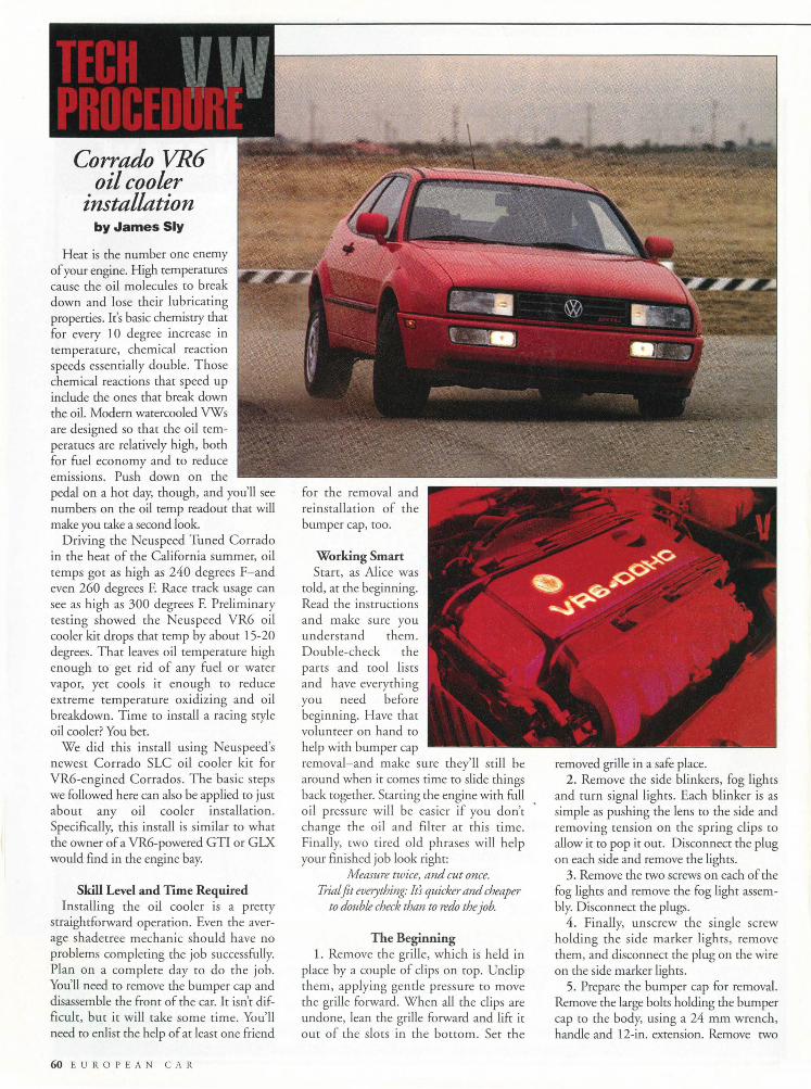
Corrado VR6 oil cooler
installation by James Sly
Heat is the number one enemy of your engine. High temperatures cause the oil molecules to break down and lose their lubricating properties. It's basic chemistry that for every 10 degree increase in temperature, chemical reaction speeds essentially double. Those chemical reactions that speed up include the ones that break down the oil. Modern watercooled VWs are designed so that the oil temperatues are relatively high, both for fuel economy and to reduce emissions. Push down on the pedal on a hot day, though, and you'll see numbers on the oil temp readout that will make you take a second look.
Driving the Neuspeed Tuned Corrado in the heat of the California summer, oil temps got as high as 240 degrees F-and even 260 degrees F. Race track usage can see as high as 300 degrees F. Preliminary testing showed the Neuspeed VR6 oil cooler kit drops that temp by about 15-20 degrees. That leaves oil temperature high enough to get rid of any fuel or water vapor, yet cools it enough to reduce extreme temperature oxidizing and oil breakdown. Time to install a racing style oil cooler? You bet.
We did this install using Neuspeed's newest Corrado SLC oil cooler kit for VR6-engined Corrados. The basic steps we followed here can also be applied to just about any oil cooler installation. Specifically, this install is similar to what the owner of a VR6-powered GTI or GLX would find in the engine bay.
Skill Level and Time Required Installing the oil cooler is a pretty
straightforward operation. Even the average shadetree mechanic should have no problems completing the job successfully. Plan on a complete day to do the job. You'll need to remove the bumper cap and disassemble the front of the car. It isn't difficult, but it will take some time. You'll need to enlist the help of at least one friend
60 EUROPEAN CAR
reinstallation of the bumper cap, too.
Working Smart Start, as Alice was
told, at the beginning. Read the instructions and make sure you understand them. Double-check the parts and tool lists and have everything you need before beginning. Have that volunteer on hand to help with bumper cap removal-and make sure they'll still be around when it comes time to slide things back together. Starting the engine with full oil pressure will be easier if you don't change the oil and filter at this time. Finally, two tired old phrases will help your finished job look right:
Measure twice, and cut once. Trial fit everything: It's quicker and cheaper
to double check than to redo the job.
The Beginning 1. Remove the grille, which is held in
place by a couple of clips on top. Unclip them, applying gentle pressure to move the grille forward. When all the clips are undone, lean the grille forward and lift it out of the slots in the bottom. Set the
removed grille in a safe place. 2. Remove the side blinkers, fog lights
and turn signal lights. Each blinker is as simple as pushing the lens to the side and removing tension on the spring clips to allow it to pop it out. Disconnect the plug on each side and remove the lights.
3. Remove the two screws on each of the fog lights and remove the fog light assembly. Disconnect the plugs.
4. Finally, unscrew the single screw holding the side marker lights, remove them, and disconnect the plug on the wire on the side marker lights.
5. Prepare the bumper cap for removal. Remove the large bolts holding the bumper cap to the body, using a 24 mm wrench, handle and 12-in. extension. Remove two
24 mm bolts on each side. Do not undo the middle, small bolt on the bumper cap mounting.
IMPORTANT: Do not drive the car without the bumper cap mountings in place! They play a major role in holding up the cross frame that supports the engine and transmission.
6. There is a series of M6 bolts along th~ edge of the spoiler. Remove them using a 10mm wrench or socket and the bumper cap is ready to remove. The front bumper cap slides right off, allowing access to the core support where we will mount our oil cooler. With the bumper cap off the car, we need to prepare the oil cooler and lines for mounting.
Prepping Oil Cooler for Mounting 7. The oil cooler has 1/2-in. tapered
pipe fittings, while the AeroQuip lines use a type of fitting call "AN," with a tapered seat. In order to match one to the other an adapter is needed on the cooler inlet and outlet. Wrap Teflon ™ tape around the adapter-or, even better and simpler, use Teflon pipe sealant paste on the threads, and hand-start each adapter. In our instal-!arion, we clamped the faces of the adapter in the vise and threaded the adapter in place in the cooler by turning the cooler
around. Pipe threads are tapered, so proceed carefully; over-tightening the adapter can split the inlets to the oil cooler.
Mounting the Oil Cooler 8. Position the upper inside edge of the
oil cooler next to the mounting bolt located at the center of the core support.
Center punch, and drill a 6mm or 1/4-in. hole. Use a block of wood or a drill stop to prevent damage to the radiator! Use our photo only as a location guide. Do not drill without either of those precautions! Deburr the hole, and protect the
raw edges with touch-up paint. Use the M6 bolt (10mm head) to mount the oil cooler directly to the core support. Bolt the cooler up loosely at this time. Bolt the three brackets loosely to the cooler using the supplied M6 bolts and nylon locking nuts. Th_r drawing in the instructions wi ll tell you which bracket goes where.
9. Have a friend hold the cooler in place approximately level, and swi ng the top bracket up to the core support. Mark a good flat surface on the core support for mounting. Center punch, and drill a 6mm or 1/4-in. hole. AGAIN! Use a block of wood or a drill stop to prevent damage to the radiator! Deburr the hole, and protect the raw edges with touch-up paint. Using the supplied M6 bolt and nylon lock nut to loosely fasten the top of the bracket to the core support. The cooler is now loosely hanging from the core support.
10. With the oil cooler loosely mounted, locate and drill the holes for the oil lines. The lines pass directly below each oil cooler outlet. J(iark each hole, keeping in mind that you will be using a 2-in. hole saw. After marking the holes, slide the cooler out of the way, pushing it back.
Center punch the location, double check the location, and drill a pilot hole. Next, double check the location by inserting the hole saw drill in the pilot hole and making sure that it will fit. If everything's okay, drill the 2-in. hole in the core support for the hose to pass through. Deburr the hole, and prot~t the raw edges with touch-up paint. Mark the second hole and repeat the procedure.
11. Mount the two lower brackets. Swing the brackets into place, just,about straight down. Mark a good flat surface on the core support for mounting. Center punch, and drill an M6 or 114-in. hole. Use a block of wood or a drill stop to prevent damage to the radiator! Deburr the hole, and protect the raw edges with touch-up paint. Use the supplied M6 bolts and nylon lock nut to loosely fasten the end of the bracket to the core support. Repeat for the second bracket.
12. With all the brackets in place, go through and tighten up each of the mounting bolts on the cooler and on the core support.
Trial Fitting the Sandwich Adapter 13. Remove the end cap from the facto
ry water to oil heat exchanger using a 17mm hex wrench. Slide the cap off. The mounting tube is attached to the stock end
M A Y I 9 9 5 61

TECH PROCEDURE VW Ht
The Neuspeed thermostatic oil cooler kit for the Corrado S LC includes a 180° F thermostatic sandwi~h adapter, and a new end cap to use. A 4. 0-in. threaded adapter, not shown, allows the thermostat plate to quickly bolt to the motor.
cap. Remove the entire assembly. Install the Neuspeed-supplied threaded pipe through the factory heat exchanger. Tighten the threaded adapter in place. APS recommends wrapping the tube with a piece of split 3/4-in. i.d. rubber hose to protect the threads and using a pair of slip joint pliers to make sure the adapter is snugly in place.
14. Install the supplied nut and tighten it down on the threaded adapter against the factory heat exchanger. Tightening torque is only 18 lb-ft (25 Nm), so don't overdo it!
15. Temporarily install the sandwich adapter with the outlets pointing downward. If you're custom fitting lines, install a -10 straight end on one end of the hose, trial fit to the sandwich adapter, and then route the hose down, a gentle radius past the transmission, and curve up through the hole to the oil cooler.
16. Double check the routing, mark the required length, remove the hose, wrap with tape and cut using a fine toothed (32 teeth per inch) hacksaw. Use low pressure and let the blade do the cutting to minimize unraveling. Install the 45-degree fitting on the cooler end, following the supplied AeroQuip directions. Blow out the hose with compressed air, making sure that it is clean and trial install the hose.
If everything fits right, repeat for the second hose.
Final Fitting With the hoses cur to length and the
ends installed, all there is left to do is the final installation, testing, and putting the bumper cap back.
17. Remove the trial-fit adapter, noting which line goes where. Install the lines to the sandwich adapter permanently. Tighten the fittings down securely. Slide the assembled thermostatic adapter up in place and install the adapter to the factory heat exchanger, putting a little motor oil on the 0-ring seal. The lines should point
62 E U R 0 P E A N C A R
down. Install the supplied nut and tighten it down on the threaded adapter against the factory heat exchanger. Tightening torque is only 18 lb-ft (25 Nm), so don't overdo it!
18. Install the new end cap, putting a little motor oil on the 0-ring seal. Tighten down in place. Tightening torque is only 18lb-ft (25 Nm), so don't overdo it!
19. Install the lines to the cooler and tighten in place using a pair of wrenches. Professionals often use a special set of aluminum wrenches to tighten down AN fittings. They don't scratch the surface as easily. In a pinch, a pair of adjustable "Crescent" style open-end wrenches and care will also do a good job.
20. In order to keep the hoses in place, they need to be clamped down. One hose is clamped to the factory power steering hose mount on the transmission, and the other hose is tie-wrapped
to it. Use the Adel clamp-the rubber covered clamp supp lied-and add it to the factory power steering hose mount on the trans . The cooler installation is now complete.
Final Checkup 21. Start the car and let it idle, check
ing for leaks. Shut off the car and correct any problems immediately. If none are found, continue to let the car idle until the oil is hot enough to let the thermostat open, about 10 or 15 minutes. Still no leaks? Great: time to reinstall the bumper cap.
AGAIN: Do not drive the car without the bumper cap mounting bolts in place! They play a major role in holding up the cross frame which supports the engine and transmission.·
Reinstalling the Bumper Cap 22. You'll need the help of a friend for
this one. As you slide the bumper cap in place, make sure that the six wire harnesses are each in place, threaded through their appropriate holes. Press the cover and bumper together. Begin at the center of the bumper cap and push together until all of the plastic clips pop into place.
23. Next, plug in the side marker lights, fog lights and turn signals. Check the lights for operation. Everything work? Reinstall each of the lights, clipping in the side blinkers and screwing in the turn signals and fog lamps.
24. Install the bumper bolts on each side and tighten down to about 63lb-ft (85 Nm).
25. Finally, install the M6 bolts along the bottom behind the spoiler, tying the bumper cap to the core support. Replace the grille, placing it in the slots in the bottom and then clipping it in place up above. That's it. You're reading for cool cruising in your Corrado SLC.
The Neuspeed adapter is thermostatically controlled, and the facrory water- · to-oil heat exchanger is retained. Oil temperatures will warm up just as quick- · ly as stock. That's important for reduced engine wear, improved fuel economy and low emissions levels. Under hard, high performance use, the Neuspeed kit adds an additional level of engine protection . ~
AUTOMOTIVE PERFORMANCE SYSTEMS, INC. 3300Col'le Molposo • Camarillo, CA 93012
805.388.7171 tel • 805.388.0030 fox • [email protected] "WWW.NEUSPEED.COM
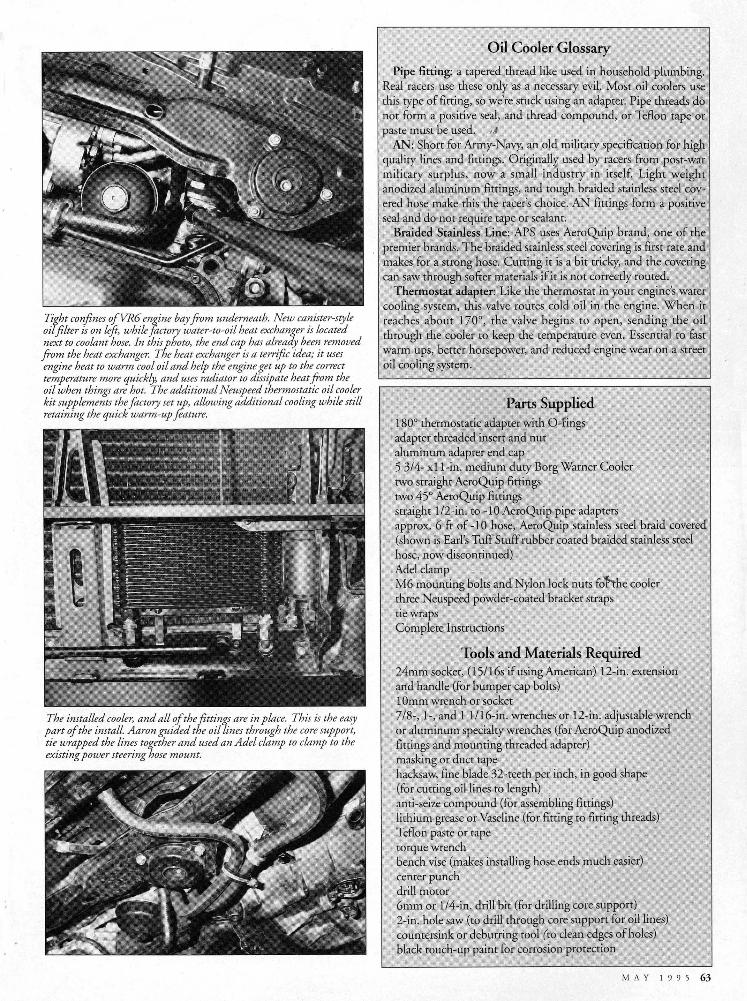
Tight confines ofVR6 en!Iine bay from underneath. New canister-style oil filter is on left, while factory water-to-oil heat exchanger is located next to coolant hose. In this photo, the end cap has already been removed from the heat exchanger. The heat exchanger is a terrific idea; it uses engine heat to warm cool oil and help the engine get up to the correct temperature more quickly, and uses radiator to dissipate heat from the oil when things are hot. The additional Neuspeed thermostatic oil cooler kit supplements the factory set z::p, allowing additional cooling while still retaining the quick warm-up f eature.
The installed cooler, and all of the fittings are in place. This is the easy part of the install. Aaron guided the oil lines through the core support, tie wrapped the lines together and used an Adel clamp to clamp to the existing power steering hose mount.
Oil Cooler Glossary
Pipe fitting: a tapered thread like used in household plumbing. Real racers use these only as a necessary evil. Most oil coolers use this type of fitting, so we're stuck using an adapter. Pipe threads do not form a positive seal, and thread compound, or Teflon tape or paste must be used. 1/
AN: Short for Army-Navy, an old military specification for high quality lines and fittings. Original!~ used by racers from post-war military surplus, now a small industry in itself. Light weight anodized aluminum fittings, and tough braided stainless steel covered hose make this the racer's choice. AN fittings form a positive seal and do not require tape or sealant.
Braided Stainless Line: APS uses AeroQuip brand, one of the premier brands. The braided stainless steel covering is first rate and makes for a strong hose. Cutting it is a bit tricky, and the covering can saw through softer materials if it is not correctly routed.
Thermostat adapter: Like the thermostat in your engine's water cooling system, this valve routes cold oil in the engine. When it reaches about 170°, the valve begins to open, sending the oil through the cooler to keep the temperature even. Essential to fast warm ups, better horsepower, and reduced engine wear on a street oil cooling system.
Parts Supplied 180° thermostatic adapter with 0-fings adapter threaded insert and nut aluminum adapter end cap 5 3/4- x 11-in. medium duty Borg Warner Cooler two straight AeroQuip fittings two 45° AeroQuip fittings straight 1/2-in. to -10 AeroQuip pipe adapters approx. 6 ft of -10 hose, Aero Quip stainless steel braid covered (shown is Earl's Tuff Stuff rubber coated braided stainless steel hose, now discontinued) Adel clamp M6 mounting bolts and Nylon lock nuts fohhe cooler three Neuspeed powder-coated bracket straps tie wraps Complete Instructions
Tools and Materials Required 24mm socket, (15116s if using American) 12-in. extension and handle (for bumper cap bolts) lOmm wrench or socket 718-, 1-, and 1 1/16-in. wrenches or 12-in. adjustable wrench or aluminum specialty wrenches (for AeroQuip anodized fittings and mounting threaded adapter) masking or duct tape hacksaw, fine blade 32-teeth per inch, in good shape (for cutting oil lines to length) anti-seize compound (for assembling fittings) lithium grease or Vaseline (for fitting to fitting threads) Teflon paste or tape torque wrench bench vise (makes installing hose ends much easier) center punch drill motor 6mm or 1/4-in. drill bit (for drilling core support) 2-in. hole saw (to drill through core support for oil lines) countersink or deburring tool (to clean edges of holes) black touch-up paint for corrosion protection
MAY 1995 63