euronite new industrial furnaces of higher thermal ... · furnaces, structural heat losses (i.e.,...
TRANSCRIPT

EEUURROONNIITTEE
New industrial furnaces of higher thermal efficiency through intensification of heat transfer from flames; EURONITE
T. ABBAS AND F. SCOTT
CINAR Ltd 11 Elvaston Place
London SW7 5QG
United Kingdom
Contract JOE3-CT97-0083
Publishable final report
01.01.1998 to 30.9.2000
Research funded in part by THE EUROPEAN COMMISSION
in the framework of the Non Nuclear Energy Programme
JOULE III

1. ABSTRACT The glass industry is one of the major energy intensive sectors. Approximately 45% of energy is utilised in the melting of the glass raw material. In modern regenerative glass furnaces, structural heat losses (i.e., furnace walls) contribute up to 20-25 % of the energy input and flue gases carry another 20-30 % of the energy away. In order to increase the efficiency of these modern glass melting furnaces or design of future energy efficient furnaces, it is important to improve the heat transfer to the glass melt. Detailed numerical calculations show that radiation from the flames and the crown of the glass-melting furnace contributes more than 95% of the heat transfer to the melt. Therefore, it is very important to increase the heat transfer from the flame by increasing the radiating surface of the flame (change of flame shape) and residence time of the combustion products in the furnace. As a result, more intensified combustion with an improved heat transfer and a lower flue gas temperature at the outlet of the furnace chamber and prior to regenerators/recuperator is achieved. Tests carried out to date using oxygen-enriched flames (oxy-fuel burners) and regenerative systems have led to energy saving up to 10% as well as 20% reductions in the CO2 emissions. However, intense combustion and resulting high temperature will increase the emissions of nitrogen oxides. In the open literature, a recent research project has addressed these issues to a certain extent but at substantially lower combustion temperature where the NOx emissions remained low and were not pertinent to glass melting furnaces. The primary aim of the ‘EURONITE’ project was to reduce the size of combustion chamber for reduced heat losses, energy consumption and CO2 production as well as keeping the NOx emissions low through combustion intensification and aerodynamics optimisation. To achieve this, an eight partner consortium from five European Countries was formed, consisting of four academic partners, two industrial partners, one research establishment and a small and medium size enterprise. The approach to the project has been fundamental mathematical modelling and experimental studies, pilot-scale data collection and model validation, and finally extrapolation of the results for industrial applications. The results obtained are very promising in that detailed mathematical models for high temperatures (oxygen-enrichment) and air vitiation conditions have been constructed and laboratory and pilot-scale data related to NOx under oxygen-enrichment and flue gas recirculation have been compiled. Finally, the design of a prototype FLOX burner has been accomplished which will provide a solid foundation for the design of an industrial energy efficient and low-NOx glass furnace. Keywords: Glass melting furnaces, NOx and CO2 reduction, low-NOx burners, Flameless oxidation, oxygen enrichment
2. PARTNERSHIP The following partners were involved in the research activities undertaken for the Euronite Project (JOE-3-CP97-0083): Cinar Ltd (Project Co-ordinator) Address: 11 Elvaston Place London SW7 5 QG Telephone: +44 20 7581 2245 Fax: +44 20 7581 2265 Contact person: Dr. T. Abbas E-mail: [email protected] Technische Universiteit Delft Address: Faculty of Applied Physics, PO Box 5046, Delft 2600, GA Holland Telephone: +31 15 2782477 Fax: +31 15 278 1204 Contact person: Dr. Ir.Th.van der Meer E-mail: [email protected] Faculte Polytechnique de Mons Address: rue de l’Epargne, 56, B-7000 Mons, Belgium Telephone: +32 65 37 4462 Fax: +32 65 37 4400 Contact person: Prof. P. Lybaert E-mail: [email protected] Ruhr Universitat Bochum Address: Universitatsstr. 150, Gebaude IB 3/136, D-44780 Bochum, Germany Telephone: +49 234 700 6333 Fax: +49 234 709 4227 Contact person: Prof. Ing Hans Kremer E-mail: [email protected] Instituto Superior Tecnico Address: Av. Rovisco Pais, 1096 Lisboa Codex, Portugal Telephone: +3501 1 8417372 Fax: +3501 1 8475545 Contact person: Prof. M. C. Carvalho E-mail: [email protected]

WS Warmeprozesstechnik gmbH Address: Dornierstr. 14, Renningen, D-71272, Germany Telephone: +49 7159 16320 Fax: +49 7159 2738 Contact person: Dr. J. G. Wunning E-mail: [email protected] Gaswarme Institut e.V. Address: Hafenstrasse 101, D-45356, Germany Telephone: +49 201 361 8248 Fax: +49 201 361 8238 Contact person: Dr. M. Flamme E-mail: [email protected] Heye Glas Address: Hermann Heye, Lohplatz 1, D-31683 Obernkirchen, Germany Telephone: +49 572 426 430 Fax: +49 572 426 220 Contact person: Dipl. Ing. Portner E-mail: [email protected]

3. OBJECTIVES In glass melting furnaces, the process temperatures and the air preheating temperature are high, which result in the heat losses through the walls and flue gases as well as higher emissions of NOx. Until now there has been no technical solutions on the market to retrofit glass tanks for example with new low-NOx and energy burner units. For NOx control, industry is left with the option of post-formation clean up in order to comply with the legislative emission standards. These techniques generally referred as SCR or SNCR (selective catalytic reduction or selective non-catalytic reduction, respectively) sometimes are inconvenient to apply due to the temperature constraints of the flue gases. However, it is more costly in terms of capital outlay and in terms of operating expenses to reduce NOx emissions by removing the undesirable pollutants after they have been formed. If, for example, the SCR technology has to be installed at glass tanks in order to reduce the NOx limits, the economical situation of the glass industry within the EU would become worse, especially when facing competition from the glass industry in the East-European countries. The aim of the ‘EURONITE’ project was to reduce the size of combustion chambers for reduced heat losses and energy input to CO2 production as well as keeping the NOx emissions low from glass melting furnaces, through combustion intensification and aerodynamics optimisation. In glass melting furnaces the process temperatures and the air preheating temperature are high which result in heat losses through the walls and flue gases as well as higher emissions of NOx. Until now there have been no technical solutions on the market to retrofit glass tanks for example with new low-NOx and energy burner units. For NOx control, industry is left with the option of expensive and complicated post-formation clean up (SCR or SNCR, selective catalytic reduction or selective non-catalytic reduction, respectively) in order to comply with the legislative emission standards. The aim of this project was to provide the vital information related to the heat transfer characteristics and NOx formation through detailed experimental data archive and supporting mathematical modelling results. Upon completion of the project, we think that we have been able to identify burner and furnace design and operating conditions that would lead to low-NOx emissions (through reduced peak flame temperatures) while maintaining the required heat transfer to the load. 4. TECHNICAL DESCRIPTION The focus of this project has been on the intensification of combustion techniques through preheating the combustion air and oxygen enrichment methods in order to enhance the heat transfer to the melt and reduce both CO2 and NOx emissions. The combination of these techniques have mainly been developed through tests in ‘empty’ combustion chambers, since emphasis was put on the combustion process itself. The study of heat transfer to the load both by radiation and convection has up to now received little attention. In recent research projects, water-cooled combustion chambers have been tested with low-NOx and flameless oxidation burners. In these low-temperature processes, the main objective was to increase the heat release per unit volume without enhancing the unburned gases including hydrocarbon and carbon monoxide emissions. The emissions of nitric oxide, due to the lower temperature, were not considered to be an important factor. Another such example is the NADO project in Japan, which has recently been completed. In this project, some preheat and oxygen enrichment techniques were effectively employed where the emphasis again was on the lower temperature industrial process of aluminium manufacturing rather
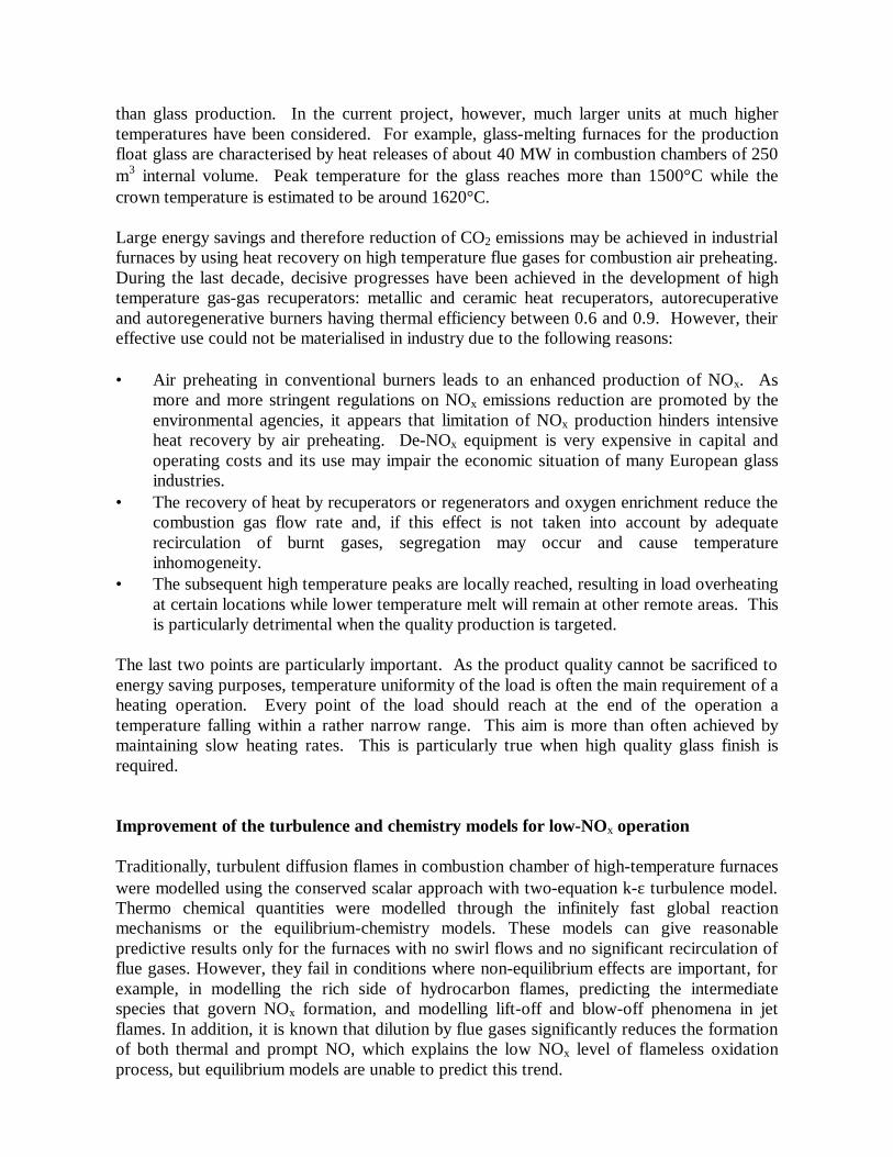
than glass production. In the current project, however, much larger units at much higher temperatures have been considered. For example, glass-melting furnaces for the production float glass are characterised by heat releases of about 40 MW in combustion chambers of 250 m3 internal volume. Peak temperature for the glass reaches more than 1500°C while the crown temperature is estimated to be around 1620°C. Large energy savings and therefore reduction of CO2 emissions may be achieved in industrial furnaces by using heat recovery on high temperature flue gases for combustion air preheating. During the last decade, decisive progresses have been achieved in the development of high temperature gas-gas recuperators: metallic and ceramic heat recuperators, autorecuperative and autoregenerative burners having thermal efficiency between 0.6 and 0.9. However, their effective use could not be materialised in industry due to the following reasons: • Air preheating in conventional burners leads to an enhanced production of NOx. As
more and more stringent regulations on NOx emissions reduction are promoted by the environmental agencies, it appears that limitation of NOx production hinders intensive heat recovery by air preheating. De-NOx equipment is very expensive in capital and operating costs and its use may impair the economic situation of many European glass industries.
• The recovery of heat by recuperators or regenerators and oxygen enrichment reduce the combustion gas flow rate and, if this effect is not taken into account by adequate recirculation of burnt gases, segregation may occur and cause temperature inhomogeneity.
• The subsequent high temperature peaks are locally reached, resulting in load overheating at certain locations while lower temperature melt will remain at other remote areas. This is particularly detrimental when the quality production is targeted.
The last two points are particularly important. As the product quality cannot be sacrificed to energy saving purposes, temperature uniformity of the load is often the main requirement of a heating operation. Every point of the load should reach at the end of the operation a temperature falling within a rather narrow range. This aim is more than often achieved by maintaining slow heating rates. This is particularly true when high quality glass finish is required. Improvement of the turbulence and chemistry models for low-NOx operation Traditionally, turbulent diffusion flames in combustion chamber of high-temperature furnaces were modelled using the conserved scalar approach with two-equation k-ε turbulence model. Thermo chemical quantities were modelled through the infinitely fast global reaction mechanisms or the equilibrium-chemistry models. These models can give reasonable predictive results only for the furnaces with no swirl flows and no significant recirculation of flue gases. However, they fail in conditions where non-equilibrium effects are important, for example, in modelling the rich side of hydrocarbon flames, predicting the intermediate species that govern NOx formation, and modelling lift-off and blow-off phenomena in jet flames. In addition, it is known that dilution by flue gases significantly reduces the formation of both thermal and prompt NO, which explains the low NOx level of flameless oxidation process, but equilibrium models are unable to predict this trend.

To take these effects into account, the flamelet modelling approach is seen as a promising general solution to the problem of detailed non-equilibrium flame chemistry [1], [2] and [3]. The flamelet concept views the turbulent flame as an ensemble of asymptotically thin, laminar, locally one-dimensional layers, called flamelets, or flamelet structures, which are embedded within the turbulent flow field. The flamelet structure can be conveniently presented in mixture fraction space, whereas the "outer" conditions can be described by certain parameters. Once the flamelet structure at the prescribed parameters has been resolved as a function of mixture fraction, and is available in the form of a flamelet library, then all thermo-chemical quantities (i.e., temperature, density, species concentrations and species reaction rates) are known as functions of these parameters and mixture fraction. An example of a flame for which its geometry can be entirely and unambiguously mapped into the mixture fraction space is an opposed-jet diffusion flame. This counter flow diffusion flame in cylindrical geometry can be reduced, via a similarity transformation, to one-dimensional problem, thus representing the flamelet structure itself. Then, to construct a library of flamelets, this 1-D flow for a given set of parameters can be numerically solved with arbitrary complicated transport properties and chemistry (for example, by the OPPDIF program [4]). As a common parameter in the laminar flamelet equations, the strain rate as (which characterizes the magnitude of velocity gradient) is used as the only one parameter characterizing each flamelet. Depending on the imposed boundary conditions, the strain rate may be either prescribed or calculated as an eigenvalue of the problem [2]. With increasing strain rate the flame becomes thinner and the volumetric heat release rate increases right up to the extinction limit. Since in glass melting furnaces the corresponding Damkohler numbers are high, the flamelet regime of combustion within asymptotically thin structures takes place, thus providing validity of this approach. Still till now, the "common" applications of flamelet modelling were mostly the turbulent reacting shear flows, free jet or confined jet flows, etc. Only one parameter (strain rate) of flamelet library was used. However, 3-D furnace aerodynamics is always influenced by the flow recirculation, therefore the effect of additional mixing, or "dilution", of the fuel and air streams with backward streams coming from the post-flame zone becomes essential. More than one parameter of flamelet library is therefore necessary. Development of a Compact Regenerative Burners for High Temperature Unit applications Initially, a large-scale laboratory furnace with a maximum rating of 0.5 MW was selected. The ancillary equipment used to simulate glass melting industrial furnaces, under controlled conditions, is briefly described here. The cylindrical down-fired furnace with an internal diameter of 600 mm consists of ten individual 300 mm high sections. The upper five of which are refractory-lined to represent the radiative part. The bottom five sections are water-cooled only, thus enabling to cool combustion products prior to their recirculation back to the furnace inlet. The primary flame is established using a simple multi-concentric swirl stabilised natural gas burner. The configuration allowed for interchange of fuel/oxygen inlets with various inlet velocities. The data are also useful for economical axi-symmetrical CFD calculations for the validation of the models developed by other project partners. The secondary air was supplied by a paddle-bladed fan and driven by an A.C motor via a speed control ‘task unit’. The ‘task’ driver was controlled through a speed control console. The air supplied from this fan was electrically preheated to the temperature between 200-

300ºC. For this project, a new air heater has been installed which will allow secondary air temperatures to be maintained between 600-800ºC, depending on the thermal load. The secondary airflow rate was measured with a calibrated orifice plat installed at the air intake of the fan. The air was then fed into a variable swirl generator through an octagonal inlet manifold leading to four equidistance radial ports. A controller and two Pt/Pt 13% Rh thermocouples close to the furnace inlet record and control the secondary air temperature. Two flue gas recirculation (FGR) lines are incorporated in the system. The gases are taken from the dry cyclone scrubber and directed to either the primary air compressor or the secondary air fan inlet. For the primary air recirculation, a dedicated positive displacement compressor was installed and its intake especially modified for in-line ‘air’ flow rate. Secondary air recirculation was achieved by taking the exhaust gases out of the top of the dry cyclone scrubber. Two variable port valves and a T-junction with an ambient airport are used to control the level of FGR from 0% i.e., ambient air firing, to 100%, i.e., full secondary air FGR. A permanent dry sampling probe was inserted downstream of the fan to read the secondary air composition and a nickel:chromium/ nickel:aluminium thermocouple was placed near the orifice plate so that the exact flow rate could be calculated by making corrections for the gas temperature and composition. An oxygen injection system has also been installed and tested for Safety by Air Products Ltd. Oxygen was taken from two oxygen mini tanks each containing the liquid equivalent of 133m3 gaseous oxygen at NPT. With the aid of a pressure regulator, the pressure downstream of the tanks was kept at 150 psi. A flow control panel that consisted of a calibrated orifice, a pressure transducer, two in-line pressure gauges and two solenoid valves controlled the gas flow rate through the 1/2” copper pipe-work. A programmable electronic control paned constantly read the signals from the pressure transducer and the two in-line pressure gauges and displayed the current oxygen flow rate and the total amount of oxygen consumed. Three different oxygen injection locations are available using flexible armoured PTFE hoses. Secondary air enrichment was achieved by injecting oxygen into the secondary air stream downstream of the heater through a multi hole injection lance thus ensuring rapid mixing with the air. The flue gas recirculation and oxygen injection systems were tested for a number of standard conditions by the supplier (Air Products) and were handed over for the planned tests. A set of tests were planned and conducted during the December 1998. Gas species measured include oxygen, carbon dioxide, carbon monoxide, nitrogen oxides, furnace wall temperatures and radiation flux. For measurements a new burner arrangement where it was possible to inject pure oxygen either through the burner central tube or through the annular tube was used. Initially, flame stability limits were established in order to define the operational variables. Once the base case conditions were established further flames were studied using the flue gas recirculation with and without oxygen injection. This way, more than 70 flames were established using both burner configurations (APF/CPF) as well as flue gas recirculation (air vitiation levels as low as 12% oxygen in the combustion air) and oxygen enrichment. Significant differences in flame shape, intensity, stability performance and NOx emissions were observed and recorded when various oxygen enrichment levels along with combustion products recirculations were introduced using the two-injection locations of the burners APF ('annular primary fuel', i.e. natural gas through the annular tube) and CPF ('central primary fuel', i.e. natural gas through the central tube). The resulting flame changes were a

manifestation of the influence of each primary air/fuel jet design on the aerodynamics of the Internal Recirculation Zone (IRZ). This region was created immediately downstream of the jet as a result of the influence of the swirling combustion airflow. The APF burner produced a strong recirculation zone as a consequence not only of the swirl level, but also of the effect of the bluff body in the burner gun. This resulted in an IRZ that was attached to the gun and filled a high proportion of the divergent quarl. Primary air penetration into this strong recirculation zone was limited. As a consequence, intense mixing initiated areas of high turbulence, gas temperature and high NOx concentrations. A change to the CPF burner injection, with the same cross-sectional area as compared with the APF, produced a longer, slower mixing flame with lower NOx emissions. The effects of operational conditions, levels of air vitiation, oxygen enrichment on flame stability and NOx are briefly summarised as follows: As expected, the NOx emission of the APF regime remained higher than that of the CPF as the excess air was increased. Secondary air swirl number seemed to have little, if any effect on the APF emission, while NOx increased with swirl in the CPF case as the length of the flame decreased, thereby increasing the intensity of air-fuel mixing, with the resulting higher maximum temperatures leading to increased NOx emissions. The effect of FGR was more pronounced for the APF burner, which became unstable at air vitiation levels where oxygen concentration fell below 18%, while values below 14% have been achieved using the CPF regime. When both oxygen enrichment and FGR were operated simultaneously, for oxygen concentrations up to 18%, the NOx values remained slightly higher for the APF case than that of the CPF, while they increased sharply for the latter above 18% oxygen but not so sharply in the APF case. This reveals, as expected, that direct contact between pure oxygen stream and natural gas, in the flame at higher oxygen concentrations, (above 18%) leads to higher peak temperatures and correspondingly higher NOx emissions. Influence of low NOx conditions and high air preheat on flame radiation to the load Radiation was the dominating heat transfer mode in high temperature furnaces. In case of air preheating, the average flame temperature will increase enhancing radiative heat transfer. The aim of FPM partner was to develop methods able to predict the radiative heat flux to the load as a function of burner design and of process temperatures. Simultaneously, effect of air preheating on NOx production was investigated in relation to burner design. As several other partners have dedicated their efforts to glass melting furnaces, FPM proposed, at the kick-off meeting, to study burner types, which may also be applied to other sectors, and particularly to steel reheating products. The selected burners are: • Burner A : a variable swirl burner with air staging. This type of burner was presently
used in lower zones of walking beam furnaces (discharge temperature 1250°C) and was considered as the state-of-the art in the European steel industry for this application. Current air preheat was 400 to 600°C.
• Burner B: a regenerative burner working in the flameless oxidation mode (also referred as mild combustion). Air preheat may reach 900°C according to furnace operating conditions. Flameless oxidation was based on high flue gas recirculation rate.

This research strategy has been proposed by FPM to follow the main research initiatives of the Japanese NITE programme. Comparison of radiative flux achieved by various types of burners was not straightforward, since working conditions may differ. Therefore, it has also been decided to evaluate measured heat fluxes with respect to those predicted by a simple model: the well-stirred model assuming that radiation was essentially due to CO2-H2O, neglecting soot and other transient species radiation. Development, design and manufacturing of a Proto-Type-FLOX® burner – using Flameless Oxidation Flame stability is a vital feature for combustion to ensure functionality, safety, efficiency and reducing the release of unburned or incomplete burnt fuel. The fuel reacts in relatively thin surfaces of the flame, which could be steady at a location in the case of laminar flames and could be unsteady and in a more chaotic structure in turbulent flames. Main characteristics of combustion in flames are:
• Reaction of fuel and an oxidizer (usually air) at high temperatures • High temperatures at the stabilization point • Visible flame in most cases either yellow, if soot formation takes place, or blue
(typical for natural gas flames) • The majority of fuel was burnt in the thin layer of the flame front. However, the
complete combustion usually takes place downstream, in the invisible post-flame zone.
Two main conditions have to be fulfilled for a flame to establish. The air (or oxygen) / fuel ratio must be within the flammability limits [5] and there must be an ignition source for the reaction to begin with. Once a flame was established, the flame itself usually was the source of ignition for the inflowing fuel and air. Günther states that there must be a balance between flow- and flame-velocity [6]. Pilot burners, hot burner parts and the walls around the burner could also function as ignition source. High temperatures enhance the stability of flames but are also resulting in high levels of thermal NOx formation. The developed burner showed very promising results, especially regarding NOx-emissions, while still being of simple design. The developed prototype burner was installed for Pilot-scale testing at GWI’s furnace to verify the performance under real technical conditions. Pilot-Scale Experiments The research work was focused on the optimisation and intensification of combustion techniques for glass melting furnaces with recuperative air preheating. Energy savings and therefore CO2 emission reduction combined with decreased NOx emissions were the main targets of the project. Different methods of combustion with preheated combustion air and oxygen have been investigated in order to enhance the heat transfer to the load and to improve the furnace efficiency. Improvement of radiative heat flux at suitable wavelength were done by adaptation of spectral radiative characteristics of the flame to the absorption spectrum of

the load. Some fundamental investigation took place in order to facilities the interpretation of the experimental results. Five different burners were investigated, as shown in Figure 1. Starting with a standard burner and a staged burner, which are in industrial operation, a new staged burner, a new flameless oxidation burner and an oxy-fuel burner were tested. As a result, there was extensive data available to characterise the flames and the suitability for different types of glass and glass furnaces. In addition, the experimental results serve as comparison data for mathematical modelling validation.
Heye Standard Burner (800 kW)
fuel gas
preheatedcombustion air
(800 °C)
furnace wall
Heye Staged Burner (800 kW)
fuel gas
preheatedcombustion air
(800 °C)
furnace wall
WS FLOX® Burner (Steel, 740 kW)
fuel gas
preheatedcombustion air
(800 °C)
furnace wall
WS FLOX® Burner (Concrete, 800 kW)
fuel gas
preheatedcombustion air
(800 °C)
furnace wall
WS FLOX® Burner (Ceramic, 740 kW)
fuel gas
preheatedcombustion air
(800 °C)
furnace wall
GWI Staged Burner (670 kW)
fuel gas
preheatedcombustion air
(800 °C)furnace wall
primary air nozzle
secondary air nozzle
Figure 1: Schematic of the tested burners
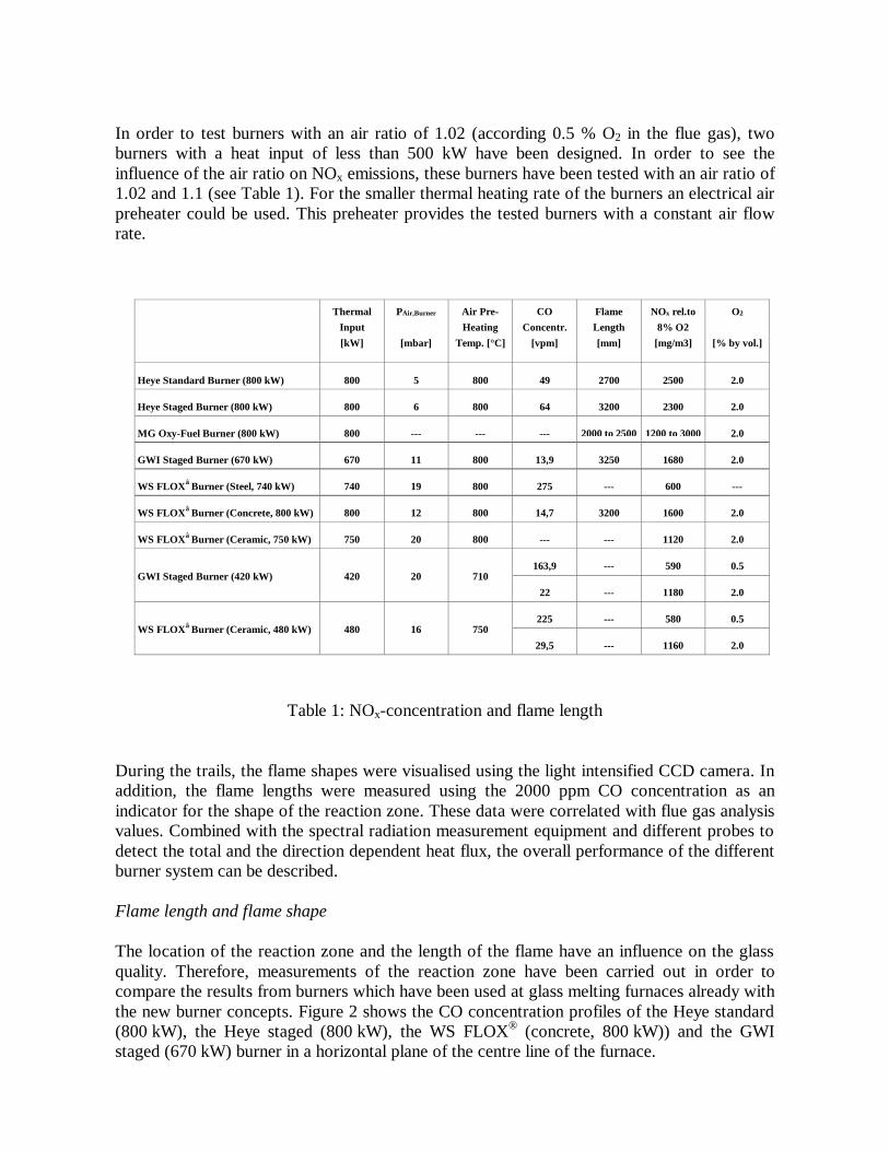
In order to test burners with an air ratio of 1.02 (according 0.5 % O2 in the flue gas), two burners with a heat input of less than 500 kW have been designed. In order to see the influence of the air ratio on NOx emissions, these burners have been tested with an air ratio of 1.02 and 1.1 (see Table 1). For the smaller thermal heating rate of the burners an electrical air preheater could be used. This preheater provides the tested burners with a constant air flow rate.
Table 1: NOx-concentration and flame length
During the trails, the flame shapes were visualised using the light intensified CCD camera. In addition, the flame lengths were measured using the 2000 ppm CO concentration as an indicator for the shape of the reaction zone. These data were correlated with flue gas analysis values. Combined with the spectral radiation measurement equipment and different probes to detect the total and the direction dependent heat flux, the overall performance of the different burner system can be described. Flame length and flame shape The location of the reaction zone and the length of the flame have an influence on the glass quality. Therefore, measurements of the reaction zone have been carried out in order to compare the results from burners which have been used at glass melting furnaces already with the new burner concepts. Figure 2 shows the CO concentration profiles of the Heye standard (800 kW), the Heye staged (800 kW), the WS FLOX® (concrete, 800 kW)) and the GWI staged (670 kW) burner in a horizontal plane of the centre line of the furnace.
ThermalInput[kW]
PAir,Burner
[mbar]
Air Pre-Heating
Temp. [°C]
COConcentr.
[vpm]
FlameLength[mm]
NOx rel.to8% O2
[mg/m3]
O2
[% by vol.]
Heye Standard Burner (800 kW) 800 5 800 49 2700 2500 2.0
Heye Staged Burner (800 kW) 800 6 800 64 3200 2300 2.0
MG Oxy-Fuel Burner (800 kW) 800 --- --- --- 2000 to 2500 1200 to 3000 2.0
GWI Staged Burner (670 kW) 670 11 800 13,9 3250 1680 2.0
WS FLOX Burner (Steel, 740 kW) 740 19 800 275 --- 600 ---
WS FLOX Burner (Concrete, 800 kW) 800 12 800 14,7 3200 1600 2.0
WS FLOX Burner (Ceramic, 750 kW) 750 20 800 --- --- 1120 2.0
163,9 --- 590 0.5GWI Staged Burner (420 kW) 420 20 710
22 --- 1180 2.0
225 --- 580 0.5WS FLOX Burner (Ceramic, 480 kW) 480 16 750
29,5 --- 1160 2.0

The four burners have roughly no big difference in flame length. The flame length varies between 2.7 and 3.24 m. For the staged burners and the FLOX® burner, the reaction zone was located further downstream compared with the standard burner. Therefore, these flames are, slidely longer (about 0.5 m) compared with the standard burner. For the oxy-fuel burner, it was not possible to use the suction pyrometer in the near burner region because of the high temperature in that region. The flame length of this burner was measured with CO concentration measurements further downstream of the mean reaction zone at the center line of the furnace. Depending on the ratio of primary and secondary oxygen, the length of the flame varied between 2 and 2.5 m.
Figure 2: CO concentration profiles for different burners
0 1000 2000 3000 4000 50000
200400600800
1000
0 1000 2000 3000 4000 50000
200400600800
1000
0 1000 2000 3000 4000 50000
200400600800
1000
0 1000 2000 3000 4000 50000
200400600800
1000
9E3 -- 8E3 -- 9E3 7E3 -- 8E3 6E3 -- 7E3 5E3 -- 6E3 4E3 -- 5E3 3E3 -- 4E3 2E3 -- 3E3 1E3 -- 2E3 0E3 -- 1E3
Heye Staged Burner (800 kW)
Heye Standard Burner (800 kW)
WS FLOX Burner (Concrete , 800 kW)
Furnace length [mm]
Furn
ace
wid
th [m
m]
GWI Staged Burner (670 kW)
ppm

Figure 3: Camera recordings of the OH intensity for different flames
Viewport 1 Viewport 2
Heye Staged Burner (800 kW)
WS FLOX Burner (Concrete , 800 kW)
GWI Staged Burner (670 kW)
Heye Standard Burner (800 kW)
MG Oxy-Fuel Burner (800 kW)
roughly 500 mm roughly 500 mmroughly500 mm

For the Heye standard and the Heye staged burner, a bright and large area of radiation from OH radicals (Figure 3) could be detected in the near burner region. That indicates that the combustion intensity was high in that region. One of the reasons for this was the intensive mixing of fuel gas and air within the burner brick. For the flameless oxidation burner, it can be seen clearly that the reaction takes place downstream of the near burner region, whereas for the GWI staged burner the reaction zone was adjusted directly to the burner. Due to higher air and fuel gas velocities, the new burners recirculate higher amounts of flue gas into the reaction zone so that the combustion intensity was smaller than in case of the Heye standard and Heye staged burner. If one compares the OH concentration of the burners with their NOx emissions, it becomes clear that high combustion intensity with higher OH concentration in the reaction zone leads to higher temperatures in the reaction zone and, as a result, a higher formation of thermal NOx in that regions. From the investigations of the flame shape (CO profiles), one can conclude that the flame length was roughly in the same range for all burners. From this point of view, it must be possible to use the new burners in glass furnaces. The OH measurements indicate that the combustion intensity of the new burners was lower compared to the conventional burners. That leads to big differences in NOx emission. If there was an influence of this decrease in combustion intensity on heat transfer, this has to be investigated with heat flux measurement equipment. Extrapolation of heat transfer and NOx formation to industrial furnace configurations As several partners are dedicating their work to glass melting furnaces, it was agreed to study another industrial sector offering many potential applications for intensified combustion techniques, i.e. the iron and steel industry. The steel-reheating furnace has been selected as a test case. The objective was to assess the benefits of using regenerative FLOX burners (burner B) instead of "classical" combustion techniques with central combustion air preheating.
Figure 4: Comparison between a kiln using “classical” burners and a kiln using FLOX burners
Central heat recovery Classical burners
Decentralized recovery autorecuperative burners

A ‘classical’ continuous kiln, with central air preheating, significantly differs from a kiln equipped with autoregenerative, e.g. REGEMAT FLOX burners (Figure 4). In the classical kiln, heat recovery on the flue gases was achieved first by preheating the load in the preheating zone of the furnace and then by preheating combustion air in a single air preheater, while in a kiln equipped with autoregenerative burners, each burner has its own air preheater and heat recovery was mainly achieved by air preheating. The structures of both furnaces are then significantly different. The classical kiln usually consists of a minimum of three sections: • A heat recovery section, with no burners, where load preheating was provided by cooling
of the gases coming from the following section, • A preheating section, equipped with burners, where the load was heated up to the
treatment temperature (or a few tenths degrees lower), • A soaking section, equipped with burners, where the load temperatures are allowed to
equalise. On the other hand, in a kiln equipped with autorecuperative or autoregenerative burners, there was no preheating section and the burners are distributed all along the kiln. This usually results in a shorter kiln. Another important difference was related to flue gas flow. In a "classical " kiln, all the flue gases produced by the burners are flowing longitudinally through the kiln, while in a kiln with autoregenerative burners, 80 to 90 percent of the flue gases generated by each burner are sucked through the burner itself and only a small part of the flue gases (10 to 20 %) was flowing longitudinally through the furnace. This changes significantly convective heat transfer and operation, e.g. control zones set point temperatures, of this kind of furnace. In order to compare both alternatives and to extrapolate the pilot scale experimental results to industrial scale, a simple zonal model of continuous kilns has been developed. The model can then be used to compare the temperature history of the load and the energy consumption of the furnace. It also allows giving information about the design and operation changes that are required on the new furnace to fulfil production constraints (i.e. product temperature history). 5. RESULTS AND CONCLUSIONS Glass making is one of the major energy intensive processes. Approximately 45% of energy is utilised in the melting of the glass raw material. In modern regenerative glass furnaces, structural heat losses (i.e., furnace walls) contribute up to 20-25 % of the energy input and flue gases carry another 20-30 % of the energy to atmosphere. In order to increase the efficiency of these modern glass-melting furnaces or design of future energy efficient furnaces, it is important to improve the heat transfer to the glass melt. In this project, more intensified combustion with an improved heat transfer and a lower flue gas temperature at the outlet of the furnace chamber and prior to regenerators/recuperator was applied. Tests carried out using oxygen-enriched flames (oxy-fuel burners) and regenerative systems have led to the energy saving up to 10% as well as 20% reductions in the CO2 emissions. However, intense combustion and resulting high temperature did increase the emissions of nitrogen oxides,

which were addressed using air staging, flue gas recirculation and combustion optimisation techniques. The above mentioned targets were achieved through reducing size of the glass melting combustion chamber. This concept, based on combustion intensification and aerodynamic optimisation, reduced furnace heat losses and energy input to CO2 production while keeping the NOx emissions low. To achieve this, an eight partner consortium from five European Countries was formed, consisting of four academic partners, two industrial partners, one research establishment and a small and medium size enterprise. The approach to the project has been fundamental mathematical modelling and experimental studies, pilot-scale data collection and model validation, and finally extrapolation of the results for industrial applications. The project objectives have been accomplished in thirty-three months. The results obtained at the end of the thirty three months are very promising in that the design of a prototype type FLOX burner has been accomplished, detailed mathematical model considering high temperatures and air vitiation as well as oxygen-enrichment have been constructed and laboratory and pilot-scale data related to NOx under oxygen-enrichment and flue gas recirculation have been compiled, which will provide a solid foundation for the design of an industrial energy efficient and low-NOx glass furnace. In glass melting furnaces, the process temperatures and the air preheating temperature are high which result in the heat losses through the walls and flue gases as well as higher emissions of NOx. Until now, there have been no technical solutions on the market to retrofit glass furnaces for example with new low-NOx and energy burner units. For NOx control, industry is left with the option of post-formation clean up in order to comply with the legislative emission standards. These techniques generally referred as SCR or SNCR (selective catalytic reduction or selective non-catalytic reduction, respectively) sometimes are inconvenient to apply due to the temperature constraints of the flue gases. However, it is more costly in terms of capital outlay and in terms of operating expenses to reduce NOx emissions by removing the undesirable pollutants after they have formed. If, for example, the SCR technology has to be installed at glass tanks in order to reduce the NOx limits, the economical situation of the glass industry within the EU would become worse, especially when facing competition from the glass industry in the East-European countries. The main findings of the EURONITE project are summarized below:
1. For improved turbulence modelling, an extended flamelet model was developed as a new approach for improved CFD predictions of detailed turbulent combustion in glass-melting furnaces. The features of new model include the capabilities to account for the non-equilibrium chemistry effects in turbulent flames (including NOx and soot formation mechanisms) and the effect of recirculation of flue gases in 3-D furnace domain as well as the radiative and convective heat loss. New detailed chemical kinetic mechanism for oxidation of hydrocarbons up to C4, simultaneously including the prompt and thermal NOx formation mechanisms (in total 59 species, 333 reactions), has been elaborated.
2. The proposed model has been implemented into CFD code FURNACE v.4.0 (TU Delft).
3. Validation of computational results on experimental data obtained from the partners has demonstrated the ability of new flamelet model to predict heat transfer and species of major interest (O2, CO2, CO, OH, soot, etc.) with satisfactory accuracy providing correct qualitative trends. The comparison has also shown that NOx levels were underpredicted.

However, the simulations correctly indicated the trend of decreasing NOx emission with changing the furnace working regime (from Heye standard burner to WS FLOX burner).
4. Detailed data archive in a 0.5MW down-fired furnace was completed subsequent to the
incorporation of facilities for the recirculation of the flue gases and injection of the oxygen. In addition, a compact flame was also achieved with the construction of a dual-fuel burner, namely the annular primary fuel and central primary fuel injection facilities (APF and CPF).
5. This was followed by a detailed flame stability analysis (over 70 flames) in order to
characterise the effect of operational variation on the combustion and NOx emissions. During the second year of the project, data related to another fuel, coal, were analysed for the compact flame producing burner configuration, the APF burner concept. The results are similar to the natural gas-fired case in that the mode of oxygen mixing is the most important factor the NOx formation and emission point of view. The combustion pattern, as determine from the CO, CO2 and O2, is quite similar in terms of flame shape and its length but NOx formation increases when the oxygen is injected from the central tube as compared with the injection of the same amount from the secondary air. This is due to the fact that slower oxygen and fuel mixing takes place when oxygen is injected with the secondary air. The effect of flue gas recirculation is, again, expected to be the same, as was observed for the natural gas flames, in order to reduce the peak flame temperatures and consequently the resulting NOx emissions. This effect was further verified using the CPF mode where only 20% increase was observed for two CPF flames (under identical conditions of APF) as compared with the base case flame.
6. From the convective and radiative experimental and modelling in a bench-scale study,
using the WS FLOX burner it was found that the convective share compared to the radiative increases by using FLOX technology, but it is not higher than 5% of the heat transfer so that it can be neglected. It can be concluded that further parametric studies of both geometrical and physical conditions have the potential for improving furnace efficiency and reducing pollutant emissions. The conversion to real glass melting furnaces is recommendable.
7. Large-scale tests were conducted for two conventional burners (Heye standard burner and Heye staged burner) and compared with new burner concepts (WS FLOX burner and GWI staged burner). In addition, an advanced oxy-fuel burner (MG oxy-fuel burner) has been tested and compared with the air-fuel burners. For glass furnaces, the flame length and the location of the maximum heat transfer within the flame have an important influence on glass quality because they influence the flow distribution within the glass melt. In addition, the total heat transfer and the radiation depending on the wavelength have an important influence. The results clearly indicate that with the new burner technology it is possible to reduce the NOx emission drastically so that the 500 mg/m3 NOx limit could be achieved at glass melting furnaces. With the new burners, it is possible to achieve the same size of flames as compared with conventional burners. With the OH measurement technique, it was possible to locate the zones with high combustion intensity within the reaction zone for the different burners. The results that have been obtained with different heat flux measurement techniques indicate, that the heat flux of the new burners are in the same range like the results for the conventional burner. From these results, one can conclude that the reduced temperature in the reaction zones of the new low NOx burners have no negative influence on heat transfer. This could be explained by the fact that the high temperature region in a reaction zone of a flame has only a small volume

compared with the whole flame and the whole furnace volume. On the other hand, these high temperature regions lead to high thermal NOx formation if the temperature is high. Therefore, it is important to avoid these high temperatures in order to achieve low NOx emissions.
8. The developed industrial-scale burner showed very promising results, especially regarding
NOx-emissions, while still being of simple design. It is planned to install a prototype in a glass tank to verify the performance under real technical conditions.
9. Finally, it was observed that the combined preheating and oxygen enriched combustion
increased the overall fuel savings substantially at relatively low levels of oxygen enrichment, while at high levels of oxygen enrichment, little additional savings can be obtained.
6. EXPLOITATION PLANS 6.1 Benefits The glass industry needs to comply, for new furnaces, which will become necessary in few years time, with 500 mg/m3 of NOx emissions. Currently, glass melting furnaces with recuperative air preheating are operated with air preheating temperatures up to 800°C and furnace wall temperatures of up to 1600°C. Typical NOx concentrations for gas-fired glass melting furnaces with recuperative air preheating are between 1400 and 1600 mg/m3. Industrial glass furnaces, until now have not been able to achieve NOx emissions near 500 mg/m3. Some, low-NOx burners capable of achieving substantially low NOx emissions (100-150 mg/m3) have been designed using oxygen enrichment and flue gas recirculation techniques. However, the glass industry has been somewhat reluctant in employing them due to the enormous technical and financial risks. The aim of this project was to provide the vital information related to the heat transfer characteristics and NO formation through detailed experimental data archive and supporting mathematical modelling results. Upon application of findings of the project, we think that the industry will be able to achieve the lower-NOx emissions while maintaining the required heat transfer to the load. It is expected that the following technical benefits to the industry will be achieved: • CO2 emission reductions between 10 to 25 %. • NOx emission reductions between 40 to 70 %, depending on the process, cost analysis
and compliance with the European emissions levels. The resulting design of the future glass melting furnaces with improved energy efficiency and lower NOx and CO2 emissions will obviously lead to many environmental as well as social benefits, including a cleaner environment, better and low cost production of glass, a more prosperous glass manufacturing sector resulting in job creation and better quality of life. The participation of industrial partners, an SME and together with academics is also an added benefit in that the exploitation of the results and dissemination measured could be effectively achieved. 6.2 Exploitation Plans

In the following table the exploitation intentions of the accomplished results are briefly described. Title of exploitable result
Partners (result owners) involved
Exploitation intention
Improved combustion and turbulence models for glass industry
TUD and IST Consultancy services to burner and glass manufacturers
Experimental data base CINAR, GWI, RUB, FPM
Further R&D and consultancy
Design and manufacturing of improved glass furnaces
WS and HG Further demonstration test and commercialisation in 2003
The improved thermal and emissions performance of the glass melting furnace demonstrated in this project will reduce the costs of glass production, when commercially applied, within European glass manufacturing companies while meeting NOx emission levels. The introduction of this new flameless oxidation principle would also be offered to steel and ceramic industries where intense combustion conditions persist, similar to glass industry, to reap the developed technology’s environmental and economical benefits. 7. REFERENCES 1 N. Peters (1984). Laminar diffusion flamelet models in non-premixed turbulent
combustion. Progr. Energy Combust. Sci., vol.10, pp.319-339
2 K.N. Bray and N. Peters. Laminar Flamelets in Turbulent Flames / In: P.A.Libby and F.A.Williams, eds, Turbulent Reactive Flows, pp. 63-113. Academic Press, N.Y., 1994.
3 R. Ovink Flamelet modelling for partially premixed turbulent jet diffusion flames. Ph.D. thesis / Technische Univ. Eindhoven – 1999.
4 A.E. Lutz, R.J. Kee, J.F. Grcar, and F.M. Rupley. OPPDIF: A FORTRAN Program for Computing Opposed-Flow Diffusion Flames. Sandia National Laboratories Report SAND96-8243, 1997.
5 Zabetakis M.G., Flamability Characteristics of Combustible Gases and Vapours,
Bulletin 627, Bureau of Mines, USA, 1965 6 Günther R., Verbrennung und Feuerungen, Springer Verlag, Berlin, 1974, pp. 173 7. REFERENCES 1 N. Peters (1984). Laminar diffusion flamelet models in non-premixed turbulent
combustion. Progr. Energy Combust. Sci., vol.10, pp.319-339

2 K.N. Bray and N. Peters. Laminar Flamelets in Turbulent Flames / In: P.A.Libby and
F.A.Williams, eds, Turbulent Reactive Flows, pp. 63-113. Academic Press, N.Y., 1994.
3 R. Ovink Flamelet modelling for partially premixed turbulent jet diffusion flames. Ph.D. thesis / Technische Univ. Eindhoven – 1999.
4 A.E. Lutz, R.J. Kee, J.F. Grcar, and F.M. Rupley. OPPDIF: A FORTRAN Program for Computing Opposed-Flow Diffusion Flames. Sandia National Laboratories Report SAND96-8243, 1997.
5 Zabetakis M.G., Flamability Characteristics of Combustible Gases and Vapours,
Bulletin 627, Bureau of Mines, USA, 1965 6 Günther R., Verbrennung und Feuerungen, Springer Verlag, Berlin, 1974, pp. 173