authors.library.caltech.eduauthors.library.caltech.edu/8498/1/selpof07.pdf · an eulerian...
TRANSCRIPT
Characteristics of transitional multicomponent gaseous and drop-ladenmixing layers from direct numerical simulation: Composition effects
L. C. SelleCalifornia Institute of Technology, Pasadena, California 91125
J. Bellana�
California Institute of Technology, Pasadena, California 91125 and Jet Propulsion Laboratory,California Institute of Technology, Pasadena, California 91109-8099
�Received 13 November 2006; accepted 23 March 2007; published online 22 June 2007�
Transitional states are obtained by exercising a model of multicomponent-liquid �MC-liquid� dropevaporation in a three-dimensional mixing layer at larger Reynolds numbers, Re, than in a previousstudy. The gas phase is followed in an Eulerian frame and the multitude of drops is described in aLagrangian frame. Complete dynamic and thermodynamic coupling between phases is included.The liquid composition, initially specified as a single-Gamma �SG� probability distribution function�PDF� depending on the molar mass, is allowed to evolve into a linear combination of two SGPDFs,called the double-Gamma PDF �DGPDF�. The compositions of liquid and vapor emanating from thedrops are calculated through four moments of their PDFs, which are drop-specific andlocation-specific, respectively. The mixing layer is initially excited to promote the double pairing ofits four initial spanwise vortices, resulting into an ultimate vortex in which small scales proliferate.Simulations are performed for four liquids of different compositions, and the effects of the initialmass loading and initial free-stream gas temperature are explored. For reference, simulations arealso performed for gaseous multicomponent mixing layers for which the effect of Re is investigatedin the direct-numerical-simulation–accessible regime. The results encompass examination of theglobal layer characteristics, flow visualizations, and homogeneous-plane statistics at transition.Comparisons are performed with previous pretransitional MC-liquid simulations and withtransitional single-component �SC� liquid-drop-laden mixing layer studies. Contrasting topretransitional MC flows, the vorticity and drop organization depend on the initial gas temperature,this being due to drop/turbulence coupling. The vapor-composition mean molar mass and standarddeviation distributions strongly correlate with the initial liquid-composition PDF. Unlike inpretransitional situations, regions of large composition standard deviation no longer necessarilycoincide with those of large mean molar mass. The rotational and composition characteristics are allliquid-specific and the variation among liquids is amplified with increasing free-stream gastemperature. The classical energy cascade is found to be of similar strength, but the smallest scalescontain orders of magnitude less energy than SC flows, which is confirmed by the larger viscousdissipation for MC flows. The kinetic energy and dissipation are liquid-specific and the variationamong liquids is amplified with increasing free-stream gas temperature. The gas composition, ofwhich the first four moments are calculated, is shown to be close to, but distinct from, a SGPDF.Eulerian and Lagrangian statistics of gas-phase quantities show that the different observationframework may affect the perception of the flow. © 2007 American Institute of Physics.�DOI: 10.1063/1.2734997�
I. INTRODUCTION
Sprays in combustion devices are used as the means toincrease the surface area of the injected liquid and enhanceevaporation and combustion. Virtually all fuels used in suchpractical devices are of petroleum type, being complex mix-tures of hundreds to thousands of chemical species. Whilesome of these species may be present in the liquid in minuteconcentrations, their importance may be totally dispropor-tionate to their concentration with regard to ignition, pollu-tion or deposition, and corrosion. Despite its relevance, the
complete multicomponent aspect of the fuel, beyond thelandmark binary-species model of Landis and Mills1 that wasadopted by many others �too many papers to be cited�, hasnot received the well-deserved attention it merits until re-cently. Realizing the impossibility of accounting for eachindividual species as an element of a discrete set, which wasthe initial approach1 adopted by many investigators, a statis-tical approach has recently been developed—a methodologythat is much more attuned to large ensembles of variables.All MC-liquid statistical approaches have been based oncontinuous thermodynamics �CT� concepts. The CT theory2,3
includes an appropriate representation of the chemical poten-tial for a mixture containing numerous components and in-
a�Telephone: 1-818-354-6959. Fax: 1-818-393-6682. Electronic mail:[email protected]
PHYSICS OF FLUIDS 19, 063301 �2007�
1070-6631/2007/19�6�/063301/33/$23.00 © 2007 American Institute of Physics19, 063301-1
Downloaded 25 Jul 2007 to 131.215.225.175. Redistribution subject to AIP license or copyright, see http://pof.aip.org/pof/copyright.jsp

volves a derivation of the Gibbs function through molecularthermodynamic methods in terms of the probability distribu-tion function �PDF� describing the mixture composition. Theconcepts are fundamental and independent of the physico-chemical model chosen for the chemical potential. From aspecified initial composition PDF, the evolution of the mix-ture is determined by the physics of the situation encapsu-lated into thermodynamic relationships and/or conservationequations. Although the composition PDF generally dependson many variables, it can be tailored to depend on one or arestricted number of variables. For example, it wasshown,2,4–6 with validation, that the single-Gamma PDF�SGPDF� depending on the molar mass, m, can represent anentire homologous species class of hydrocarbons. Cottermanet al.2 have used thermodynamic relations to show that dur-ing evaporation, the same mathematical form of the PDFapplies in the gas phase as in the liquid from where the vapororiginates. The flexibility of the CT approach in terms of thePDF mathematical form and of the choice of the PDF vari-able�s� makes it very attractive.
Tamim and Hallett7 and Hallett8 have pioneered the ap-plication of CT concepts to the study of a MC-liquid dropusing a SGPDF. Their model has been adopted in practicalsimulations of spray combustors,9 in Direct Numerical Simu-lation �DNS� of a transitional mixing layer having a lowerstream initially laden with a large number �e.g., O�106�� ofdrops,10 and even to atmospheric-science hydrocarbon-partitioning studies.11 The SGPDF model has also constitutedthe point of departure for the development of models with anincreasing range of application.12–14 Specifically, Harstad etal.14 have shown that the SGPDF model depending on m,while appropriate for slow evaporation in fuel-unvitiated sur-roundings, cannot describe even qualitatively evaporationunder high-temperature or in fuel-vitiated conditions. In-stead, a double-Gamma PDF �DGPDF� has been proposed,which when exercised for single drops compared excellentlyfor most conditions with the results from a discrete-speciesmodel based on a 32-species representation. The flexibilityof the statistical representation was manifested once more inthe DGPDF model that was shown to fit all three preponder-ant homologous classes of Jet A, RP-1, and JP-7 petroleumfuels with only a single DGPDF when the PDF dependenceis on �m instead of on m.13
The recent pretransitional DGPDF DNS study of LeClercq and Bellan15 expanded on the previous SGPDF studyof Le Clercq and Bellan10 of the same mixing layer configu-ration: the DGPDF representation enables attainment of ahigher evaporation regime, and thus the results have in-creased relevance to the realistic high-temperature regime ofcombustors. Both single component �SC� and SGPDF MC-liquid representations fail in such regime. Compared to pre-vious studies,10,15 the present DNS investigation accesses ahigher-temperature turbulent-gas regime that is closer to thatof real combustors, despite the fact that the initial gas tem-perature, T0 �subscript 0 denotes the initial condition�, is stillvery much lower than in combustors. This lower T0 value isdictated by the requirement to match the drop characteristictime to that of the flow, which in this transitional regime ismuch larger than that of fully turbulent flows, known to be
inaccessible in DNS. The focus of this study is on the effectof the drop/flow interaction, which exists only as long as thedrop has not entirely evaporated. Thus, the interaction char-acteristic time is influenced by the liquid volatility, the initialdrop size, the initial gas composition, the relative differencebetween T0 and the initial drop temperature Td,0, and therelative difference between Td,0 and the liquid boiling tem-perature which for MC-liquid drops evolves with time as theliquid composition changes. To aid the unified understandingof MC turbulent flows, simulations are performed here bothfor single-phase �SP� MC flows, where the effect of the ini-tial Reynolds number, Re0, is investigated in the DNS-accessible regime, and for two-phase �TP� MC flows, wherethe effect of the initial mass loading, ML0, and higher T0 areexplored with the same model.
This investigation is conducted within the framework ofthe DNS methodology wherein all scales of the flow areresolved. Originally devised for SP flows, DNS for TP flowswith particles that are much smaller than the Kolmogorovscale and which have a volumetrically small loading��10−3� was enabled by the results of Boivin et al.16 show-ing that the drops can be treated as point sources of mass,momentum, and energy from the gas-phase perspective. It isthus appropriate to perform TP simulations using a gas-phaseresolution that is adequate for SP flow by following the gasphase in an Eulerian frame and tracking the drops in a La-grangian frame. The terminology DNS, while not strictly ac-curate, is traditionally applied to such simulations, and sev-eral recent studies have used this DNS methodology.16–21
This paper is organized as follows. In Sec. II, the con-servation equations are briefly recalled from the detailedmodel developed by Le Clercq and Bellan.15 Next, the con-figuration, boundary conditions, and the numerics are pre-sented in Sec. III. Section IV is devoted to a description ofthe results, encompassing the global layer characteristics,flow visualizations, homogeneous-plane statistics, drop-ensemble probabilities, and a dissipation analysis. Compari-sons with the SC DNS study of Okong’o and Bellan20 andwith the pretransitional DNS investigation of Le Clercq andBellan15 are also discussed. The results are summarized inSec. V and future study directions are stated.
II. CONSERVATION EQUATIONS
The model of Ref. 15 is adopted wherein the MC liquidcomposition and gas composition in the vicinity of the dropsurface are described by
P�m;�1,�1,�2,�2,�� = �1 − ��f��1� + �f�
�2�, �1�
where f��k�= f��m ;�k ,�k� with integer k=1,2 ,� is a weight-
ing parameter �0���1�, ���P�m�dm=1, and
f��m� =�m − ���−1
������exp�− �m − �
� , �2�
where ���� is the Gamma function and f��m� is a SGPDF.The origin of f is specified by � �P�m ;�1 ,�1 ,�2 ,�2 ,�� wasdeveloped in Ref. 14 with �1=�2=��, and its shape is deter-mined by � and �. At each time t, P�m ;�1 ,�1 ,�2 ,�2 ,�� isdetermined by the vector ���1 ,�1 ,�2 ,�2 ,��. According to
063301-2 L. C. Selle and J. Bellan Phys. Fluids 19, 063301 �2007�
Downloaded 25 Jul 2007 to 131.215.225.175. Redistribution subject to AIP license or copyright, see http://pof.aip.org/pof/copyright.jsp

Harstad et al.,14 P can be determined by an inverse mappingfrom its first four moments, n, where integer n� �1,4�, witha fifth parameter empirically calculated. These moments aredefined as
nl � ��
�
mnPl�m�dm, nv � ��
�
mnPv�m�dm �3�
for integer n�1, where subscripts l and v denote the liquidand vapor, respectively. Although in the vicinity of each dropsurface the vapor composition is represented by Pv accordingto Eq. �1�, away from the drops the mathematical form of Pvis determined by the vapor released from the drops and bygaseous mixing. At each t, Pl describes the liquid-fuel com-position, which is specific of each drop, and Pv describes thevapor composition, which varies with spatial location.Throughout this paper, we adopt the notation ��1 and �2, and the standard deviation of P is calculated as �
=�� −�2�. Also following Ref. 14, one can define nSGPDF as
being the moments of a SGPDF that would have the same 1
and 2 values as a specified P. Thus, “excess moments” of
any PDF P with respect to the SGPDF that has the same �and as P are defined by
n� � n − nSGPDF. �4�
By definition, 1�=2�=0 and a DGPDF then corresponds ton��0 for n�3. Deviation of any PDF from the equivalentSGPDF decreases with decreasing �n� /n
SGPDF�.
A. Gas-phase equations
The gas is followed in an Eulerian frame, and the ge-neric conservation equations for continuity, momentum, en-ergy, species, and PDF first four moments ��v , v ,3v ,4v�representing the composition are
��
�t+
���uj��xj
=�������
�xj+ S , �5�
where
� = c,cmui,cmet,cXv,cXv�v,cXv v,cXv3v,cXv4v� �6�
is the vector of the conservative variables,
���� = �cmD �
�xj�Xv
m�1 −
�v
ma, − p�ij + �ij, − puj + ui�ij + �
�T
�xj+ �1�T�
�
�xj�Xv
m + �2�T�
�
�xj�Xv�v
m
+ �3�
�xj�Xv v
m, cmD �
�xj�Xv
m, cmD �
�xj�Xv�v
m, cmD �
�xj�Xv v
m, cmD �
�xj�Xv3v
m, cmD �
�xj�Xv4v
m� �7�
is the diffusional flux vector corresponding to �, and
S = Smole,Smom,i,Sen,Smole,Smass,S ,S3,S4
� �8�
is the source term vector of components Sr associated with�. In Eqs. �5�–�7�, c is the molar density, xi is the ith spatialcoordinate, u is the mass-averaged velocity, X is the molefraction, m=�vXv+ma�1−Xv� is the molar mass, where ma isthe carrier gas molar mass �subscript a denotes the carriergas�, D is an effective diffusion coefficient defined byHarstad and Bellan13 as the proportionality coefficient be-tween the vapor mass flux and cm� �Xv /m�, p is the pres-sure, �ij is the viscous stress tensor, �ij is the Kroneckersymbol, et=ek+eint=uiui /2+h− p /� is the total energy of thegas, �=mc is the mass density, h is the enthalpy, � is thethermal conductivity, and T is the gas temperature. The lastthree terms in the heat flux of the energy equation are theportion due to transport of species by the molar fluxes; thedetailed expressions for �1�T�, �2�T�, and �3 are presented inthe Appendix. The source vector arises from the coupledinteraction of drops and gas, and is presented in Sec. II C.
The perfect gas equation of state
p = ��RuT�/m = cRuT , �9�
where Ru is the universal gas constant, closes the system ofgas-phase equations.
B. Drop equations
Each drop is individually simulated and the liquid mass-density, �l, is assumed constant although the liquid molar-density, cl, may vary. Because � /�l=O�10−3�, the gas phaseis quasisteady with respect to the liquid phase,22 and due tothe relatively small value of T0 compared to that in combus-tors, the evaporation rate is relatively low �verified in LeClercq and Bellan15� so that the assumption of uniform in-ternal drop properties is justified. The Lagrangian conserva-tion equations for each drop position �, velocity v, energy,mass Md=Vd�l=��lD
3 /6 �V and D represent volume anddiameter, and the subscript d denotes the drop�, and compo-sition are
d�i
dt= vi,
dvi
dt=
Fi
Md, �10�
�11�
md �dMd
dt= −
Sh
3Sc
Md
�dln�1 + B� , �12�
063301-3 Characteristics of transitional multicomponent Phys. Fluids 19, 063301 �2007�
Downloaded 25 Jul 2007 to 131.215.225.175. Redistribution subject to AIP license or copyright, see http://pof.aip.org/pof/copyright.jsp

dnl
dt=
3�l
2BD2
dD2
dt��Xv
m−
Xv�s�
m�s� �1 + B�nl
+Xv
�s�nv�s�
m�s� �1 + B� −Xvnv
m� �13�
for integer n= �1,4�, where the gas phase at the drop loca-tion, interpolated from the Eulerian solution, acts as the dropfar field. Fi= �Md /�d�f1�ui−vi�, where �d=�lD
2 / �18�� is theparticle time constant for Stokes flow; Td is the drop tem-perature; Cl is the liquid heat capacity at constant pressure;A=�D2 is the drop-surface area; � is the viscosity of thecarrier gas; Pr=�Cp / ��m�, where Cp is the gas heat capacityat constant pressure, and Sc�� / ��D� are the Prandtl and theSchmidt numbers, respectively; and �l=cl�l. The Nusselt,Nu, and the Sherwood, Sh, numbers are semiempiricallymodified using the Ranz-Marshall correlations, accountingfor convective heat and mass transfer effects,23 with the simi-larity assumption Nu=2+0.552 Resl
1/2�Pr�1/3 ,Sh=2+0.552 Resl
1/2�Sc�1/3. f1, given in Miller and Bellan,23
f1 =1 + 0.0545 Resl + 0.1 Resl
1/2�1 − 0.03 Resl�1 + a�Reb�b
, �14�
a = 0.09 + 0.077 exp�− 0.4 Resl�,�15�
b = 0.4 + 0.77 exp�− 0.04 Resl�
is an empirical correction to Stokes drag accounting for finitedrop Reynolds numbers using the slip Reynolds numberResl= �usl ��D /�, where usl= �u−v� is the slip velocity, andfor a Reynolds number Reb=Ub�d /� based on the evapora-tion blowing velocity Ub obtained from the mass conserva-tion relation at the drop surface, md=−��D2Ub. The correla-tion of Eq. �14� is valid in the ranges 0�Resl�100 and 0�Reb�10. B= �Yv
�s�−Yv� / �1−Yv�s�� is the Spalding number,
where Yv=Xv�v /m is the vapor mass fraction, Ya=1−Yv, and�1+BT�= �1+B�1/Le with Le being the Lewis number, Lveff isan effective latent heat14 as defined in Appendix A of LeClercq and Bellan,15 and the superscript �s� denotes the dropsurface. At this surface, the classical boundary conditions oftemperature equality and mass, species, momentum, and en-ergy flux conservation apply.22 Under the ideal-mixture as-sumption, Raoult’s law relates the drop and gas PDFs,
Pv�s� =
patm
Xv�s�p
exp� mLv�m�RuTb�m�
�1 −Tb�m�
TdPl
�s�, �16�
where patm=1 atm, and Lv�m� and Tb�m� are the latent heatand the normal boiling point, correlated as functions of m byHarstad et al.14 using Trouton’s law,
�slg = mLv/Tb � 10.6Ru, �17�
and
Tb�m� = Ab + Bbm , �18�
where Ab=241.4 and Bb=1.45 for Tb in K �see Appendix Aof Le Clercq and Bellan15 for more details�.
Thus, the drops move throughout the flow according tothe Lagrangian equations �Eqs. �10�� while heating �Eq.
�11��, losing/gaining mass �Eq. �12��, and changing compo-sition �Eq. �13��. The thermodynamics at each drop surface,i.e., evaporation versus condensation for the species havingmolar mass m, is governed by Raoult’s law, Eq. �16�. That is,during its lifetime, each drop will encounter a gas-phasecomposition that is different from that which would havebeen expected had it remained in the gas resulting from itsown evaporation, and it is this reality that produces the con-densation of certain species onto the drop. No new drops areformed through homogeneous �Ref. 24� or heterogeneousnucleation.
C. Source terms
The source-term-vector components of Eq. �8� are
Sr = − �q=1
Nwq
�Vq��r�q, �19�
� = �dNdt
, Fj +d�N�l�
dtv j, v jFj + Qconv−diff + Qevap
+ md�v jv j
2+ ClTd,
dNdt
,d�N�l�
dt,d�N l�
dt,d�N3l�
dt,d�N4l�
dt� �20�
where N=Md /�l is the number of moles in the drop, N is thenumber of drops, and the summation in Eq. �19� is over alldrops residing within a local numerical discretization vol-ume, �Vq. Following previous methodology,15,20,23 a geomet-ric weighting factor wq distributes the individual drop con-tributions to the nearest eight grid points in proportion totheir distance from the drop location. Le Clercq and Bellan10
explained that because convective effects dominate the spe-cies flux term, differential species diffusivity is negligible forMC flows in species transport from the drop location to thegrid nodes.
III. CONFIGURATION, BOUNDARY AND INITIALCONDITIONS, AND NUMERICS
The three-dimensional �3D� mixing layer configurationis displayed in Fig. 1, where the coordinates �x1 ,x2 ,x3� cor-
. .
.
... .
..
..
..
.
.
.
.
..
X1
X2
X3
-U0
+U0
δ ω,0
...
FIG. 1. Mixing layer configuration.
063301-4 L. C. Selle and J. Bellan Phys. Fluids 19, 063301 �2007�
Downloaded 25 Jul 2007 to 131.215.225.175. Redistribution subject to AIP license or copyright, see http://pof.aip.org/pof/copyright.jsp

respond to the streamwise, cross-stream, and spanwise direc-tions, respectively. The velocity difference across the layer is�U0=2U0 and its mathematical form is prescribed using anerror-function profile23 having a width given by the initialvorticity thickness ��,0=�U0 / ��u1 /�x2� ��� denotes averag-ing over homogeneous �x1 ,x3� planes�. A perturbation is im-posed on the vorticity field to promote roll-up andpairing.23,25,26 The forcing wavelengths in the x1 and x3 di-rections are l1 and l3, and their amplitudes with respect to thecirculation are 10% and 2.25%, respectively. The evolutionof the layer comprises two pairings of the four initial span-wise vortices to form an ultimate vortex in which smallscales may proliferate if the Reynolds number is highenough. The dimensions of the domain are L1
=4l1�=29.16��,0=0.2 m�, L2=1.1L1, and L3=4l3=0.6L1.The gas-phase initial condition is specified by six param-
eters: T0; the free-stream pressure p0; Re0=�a,0�U0��,0 /�,where �a,0 is the initial carrier gas �air� mass-density and � iscalculated from the specified value of Re0; the Mach numberMc,0 based on the carrier gas initial speed of sound aa,0
=�RaT0Cp,a /Cv,a, where Ra=Ru /ma and the specific heats ofthe carrier �Cp,a and Cv,a� are computed as in Ref. 27; thevapor molar fractions in the lower stream, Xv,0
l , and upperstream, Xv,0
u , here specified Xv,0l =Xv,0
u =10−4 for all TP simu-lations �this non-null value is realistic in that it simulatesdrop evaporation in vitiated air, as occurs in engines�; andthe specification of the free-stream vapor composition, whichfor each liquid is found from a single-drop simulation in airat the specified T0 by choosing it to be the first-time-stepsurface-vapor composition. For SP simulations, either Xv,0
l
=Xv,0u , in which case there is no mass flux between streams,
or Xv,0l =10−1 so as to create a vapor mass flux between the
two streams; the value of 10−1 approximately corresponds tothe average lower-stream value encountered at transitional
states in TP simulations. The free-stream velocity U0
=Mc,0aa,0 is calculated from the specified value of Mc,0. Thethermal conductivity and diffusivity �both constant� are com-puted using the value of � and specified values of Pr=Sc,0.696 at T0=375 K and 0.694 at T0=400 K, calculated as inRef. 27. The vapor heat capacity at constant pressure, Cp,v, iscalculated as in Appendix A of Le Clercq and Bellan.15 TableI lists all initial conditions and defines a baseline simulation;in addition to the Re0=500 and 600 simulations performedhere, the table also lists some Re0=200 computation condi-tions of Le Clercq and Bellan,15 as the present results will becompared to those of the listed pretransitional simulations.The initial mass loading, ML0, defined as the ratio of theinitial liquid mass to that of the gas in the lower stream, isnull for SP simulations and 0�ML0�1 for TP simulations.For TP computations, the Re0=500 simulations were close tothe limit of the memory capacity of the computational plat-form �the ML0=0.5 simulation was almost at the memorylimit�, preventing TP simulations at higher Re0.
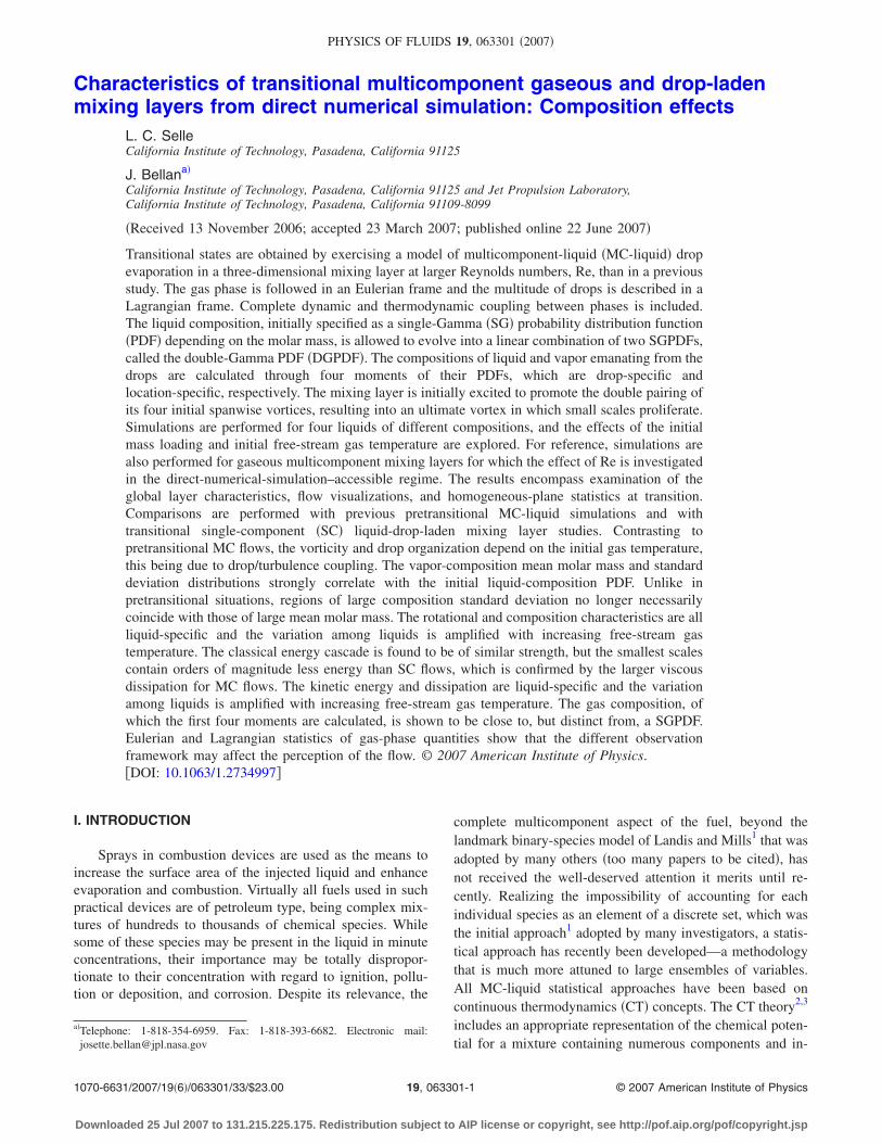
In the TP simulations, only the lower stream of the mix-ing layer �x2�0� is initially laden with drops, which arerandomly distributed with a uniform number density andhave at t=0 a null slip velocity with respect to the gas. Themean drop number density profile is smoothed near the cen-terline, x2=0, using an error-function profile. The initial con-ditions for the drops are specified by Td,0, which is uniform,with Td,0�T0 and a selected value of �T0−Td,0� to ensurethat the drop/flow interaction is captured over the entire layerevolution with a substantial number of drops remaining inthe simulation at all times �for the chosen Td,0=345 K, theseconditions were conservatively satisfied for all liquids whenT0=375 K and 400 K as shown in Sec. IV C�; ML0; theStokes number St0, where St��d�U0 /��,0; �l; and the liquidcomposition shown in Fig. 2, obtained through the selected-
TABLE I. Initial conditions. T0 in K, �l in kg/m3, D0 in m, and mean molar mass and standard deviation inkg/kmol. In all simulations, Mc,0=0.35, ��,0=6.859�10−3m, St0��=3, and �St0− St0���2��1/2=0.5, Td,0
=345 K, Xv,0u =10−4, �=86 kg/kmol for diesel, �=41 kg/kmol for Jet A, and �=93 kg/kmol for RP-1 and
JP-7. For Re0=200 the grid is 200�224�120, for Re0=500 the grid is 360�400�216, and for Re0=600 thegrid is 432�480�260. The baseline case is indicated by a superscript asterisk.
Case Fuel T0 ML0 �l Re0 Xv,0l
D0���105 �l,0 /�l,0 �v,0 /�v,0
N0
�10−3
die375ML0R5 Diesel 375 0 NA 500 Xv,0u NA NA 140.0 / 28.0 NA
die375ML0R5X Diesel 375 0 NA 500 10−1 NA NA 140.0 / 28.0 NA
die375ML0R6 Diesel 375 0 NA 600 Xv,0u NA NA 140.0 / 28.0 NA
die375ML0R6X Diesel 375 0 NA 600 10−1 NA NA 140.0 / 28.0 NA
die375ML2R2 Diesel 375 0.2 828 200 Xv,0u 12.02 185.0 / 43.0 140.0 / 28.0 670
die400ML2R2 Diesel 400 0.2 828 200 Xv,0u 11.64 185.0 / 43.0 140.0 / 28.0 690
die375ML2R5* Diesel 375 0.2 828 500 Xv,0u 7.601 185.0 / 43.0 140.0 / 28.0 2586
die375ML5R5 Diesel 375 0.5 828 500 Xv,0u 7.601 185.0 / 43.0 140.0 / 28.0 6451
die400ML2R5 Diesel 400 0.2 828 500 Xv,0u 7.359 185.0 / 43.0 140.0 / 28.0 2670
jetA375ML2R5 Jet A 375 0.2 800 500 Xv,0u 7.732 161.0 / 29.7 131.4 / 22.4 2543
jetA400ML2R5 Jet A 400 0.2 800 500 Xv,0u 7.487 161.0 / 29.7 131.4 / 22.4 2626
rp1375ML2R5 RP-1 375 0.2 800 500 Xv,0u 7.732 165.2 / 17.7 153.5 / 14.8 2600
rp1400ML2R5 RP-1 400 0.2 800 500 Xv,0u 7.487 165.2 / 17.7 153.5 / 14.8 2626
jp7375ML2R5 JP-7 375 0.2 800 500 Xv,0u 7.732 167.1 / 19.2 153.7 / 15.7 2541
jp7400ML2R5 JP-7 400 0.2 800 500 Xv,0u 7.487 167.1 / 19.2 153.7 / 15.7 2626
063301-5 Characteristics of transitional multicomponent Phys. Fluids 19, 063301 �2007�
Downloaded 25 Jul 2007 to 131.215.225.175. Redistribution subject to AIP license or copyright, see http://pof.aip.org/pof/copyright.jsp
PDF moments. Le Clercq and Bellan15 emphasize that it isnot possible to initialize all computations with the same val-ues of the total number of drops, N0, since �l does not havethe same value for all liquids and � changes with T0. Fol-lowing the well accepted methodology of comparing simula-tions performed with specified nondimensional numbersrather than physical quantities,28 the specification of ML0
and St0 determines for given �l and T0 the value of N0 andD0 �see Table I�. The initial Stokes number is specifiedthrough a Gaussian distribution with mean St0��=3 andstandard deviation � St0
2��− St0��2=0.5, where �� sym-bolizes drop-ensemble averages over all drops. Similarly tothe study of Le Clercq and Bellan,15 four fuels are consid-ered as practically significant examples of liquids, namelydiesel, Jet A, RP-1 and JP-7, whose initial composition,29
provided as a mole fraction versus the carbon number byEdwards,30 was fitted in PDF form by Harstad and Bellan.13
Table I lists the mean and standard deviation of the initialliquid PDF, Pl,0, which is assumed to be a SGPDF to enablethe examination of the potential deviation from its initialSGPDF form.
The boundary conditions in the x1 and x3 directions areperiodic, and adiabatic slip-wall conditions in the x2 direc-tion previously derived31,32 were adapted by Le Clercq andBellan15 to the DGPDF CT model for MC mixtures �seeAppendix B of Le Clercq and Bellan15�. Drops reaching theslip walls are assumed to stick to them and are otherwisefollowed using the drop equations of Sec. II B.
The equations displayed in Sec. II A were solved usingan eighth-order central finite-difference discretization inspace and a fourth-order Runge-Kutta for temporal advance-ment. To mitigate potential numerical instabilities for longCPU time simulations, following Kennedy and Carpenter,33 atenth-order filtering for spatial derivatives was used �exceptin a half-filter-size band located at the lower and upper x2
boundaries� at every time step. This filtering introduces asmall amount of dissipation that serves only to stabilize thecomputations for long-time integrations, but since it actsonly on the shortest waves that can be resolved on the grid, itdoes not act as a turbulence model and thus does not allowunder-resolved computations �see Ref. 20�. The time step
was controlled by the CFL number. The grid size is listed inTable I and scales approximately linearly with Re0.34 Thegrid resolution is approximately 10−3 m, 0.55�10−3 m, and0.46�10−3 m when Re0=200 �DNS of Ref. 15�, 500, and600, respectively. The �10−3 value of Vd0�� /�Vq �com-puted using the values of D0�� in Table I� ensures thatnumerical diffusion induced by distributing the Lagrangiansource terms at the Eulerian nodes is negligible. A fourth-order Lagrange interpolation, I, was used to obtain gas-phase variable values at drop locations. Drops with a massthat decreased below 3% of the initial mass Md,0 were re-moved from the calculation; for the conditions of this study,few drops fell below 3% of Md,0 �at the two extremes arediesel simulations, where no drops disappeared, and RP-1 atT0=400 K, where 9.8% of drops disappeared by transition�and mass was conserved in the system to a maximum rela-tive error of 5�10−5.
IV. RESULTS
A. Global layer evolution
1. Growth and dynamics
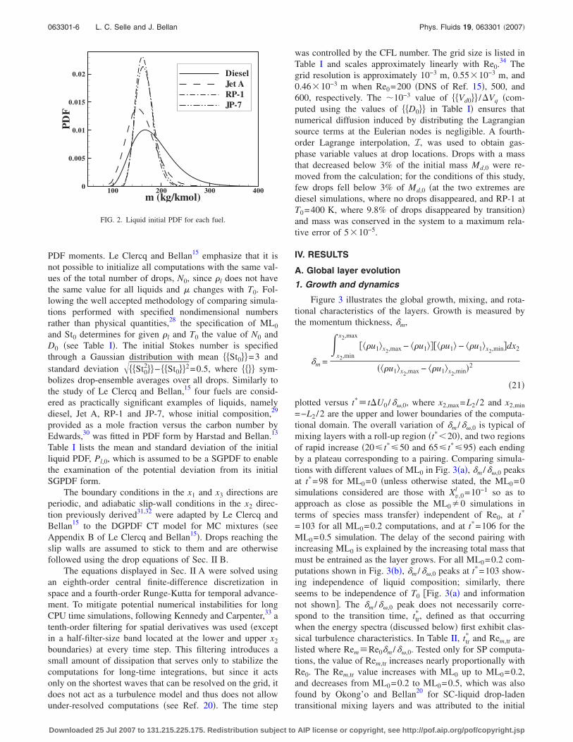
Figure 3 illustrates the global growth, mixing, and rota-tional characteristics of the layers. Growth is measured bythe momentum thickness, �m,
�m =
�x2,min
x2,max
���u1�x2,max − ��u1�����u1� − ��u1�x2,min�dx2
���u1�x2,max − ��u1�x2,min�2
�21�
plotted versus t*� t�U0 /��,0, where x2,max=L2 /2 and x2,min
=−L2 /2 are the upper and lower boundaries of the computa-tional domain. The overall variation of �m /��,0 is typical ofmixing layers with a roll-up region �t*�20�, and two regionsof rapid increase �20� t*�50 and 65� t*�95� each endingby a plateau corresponding to a pairing. Comparing simula-tions with different values of ML0 in Fig. 3�a�, �m /��,0 peaksat t*=98 for ML0=0 �unless otherwise stated, the ML0=0simulations considered are those with Xv,0
l =10−1 so as toapproach as close as possible the ML0�0 simulations interms of species mass transfer� independent of Re0, at t*
=103 for all ML0=0.2 computations, and at t*=106 for theML0=0.5 simulation. The delay of the second pairing withincreasing ML0 is explained by the increasing total mass thatmust be entrained as the layer grows. For all ML0=0.2 com-putations shown in Fig. 3�b�, �m /��,0 peaks at t*=103 show-ing independence of liquid composition; similarly, thereseems to be independence of T0 �Fig. 3�a� and informationnot shown�. The �m /��,0 peak does not necessarily corre-spond to the transition time, ttr
*, defined as that occurringwhen the energy spectra �discussed below� first exhibit clas-sical turbulence characteristics. In Table II, ttr
* and Rem,tr arelisted where Rem�Re0�m /��,0. Tested only for SP computa-tions, the value of Rem,tr increases nearly proportionally withRe0. The Rem,tr value increases with ML0 up to ML0=0.2,and decreases from ML0=0.2 to ML0=0.5, which was alsofound by Okong’o and Bellan20 for SC-liquid drop-ladentransitional mixing layers and was attributed to the initial
m (kg/kmol)
PD
F
100 200 300 4000
0.005
0.01
0.015
0.02 DieselJet ARP-1JP-7
FIG. 2. Liquid initial PDF for each fuel.
063301-6 L. C. Selle and J. Bellan Phys. Fluids 19, 063301 �2007�
Downloaded 25 Jul 2007 to 131.215.225.175. Redistribution subject to AIP license or copyright, see http://pof.aip.org/pof/copyright.jsp

forcing that has a relatively weaker influence on the highestML0 value layers; that is, SP flows do not behave merely asa simple limit of TP flows. Although a small variation, atT0=375 K the value of Rem,tr increases with increasing meanliquid molar mass, which is attributed to the decreased liquidvolatility and consequently to the larger residual drop massthat promotes turbulence through drop/flow interactions. AtT0=400 K, the three kerosenes have similar Rem,tr values,which are distinctively smaller than that for diesel, showingthat liquid-specificity effects increase with larger T0. There-fore, the growth of the layer seems insensitive, but the globaltransitional characteristics seem mildly sensitive to the liquididentity.
The plot of MG /MG,0 in Figs. 3�c� and 3�d�, where MG isthe gas-phase mass, gives a direct measure of global massevolution. Expectably, no change in the initial amount ofvapor occurs when ML0=0, but either an increase in ML0 orin T0 results in an augmentation in MG /MG,0, as shown inFig. 3�c�. The major augmentation occurs before roll-up, af-ter which MG /MG,0 increases more gradually and at gener-ally similar rates for all diesel simulations, independent ofML0 or T0 values. However, the augmentation in MG /MG,0
occurs during the early time before roll-up for the larger ML0
and during the late time before roll-up at the higher T0, and isa much stronger function of T0 than of ML0. The strongestparameter influencing MG /MG,0 is the fuel composition, as
(a) t∆U0/δω,0
δ m/δ
ω,0
0 20 40 60 80 100 1200
1
2
3
(b) t∆U0/δω,0
δ m/δ
ω,0
0 20 40 60 80 100 1200
1
2
3
(c) t∆U0/δω,0
MG/M
G,0
0 50 1001
1.01
1.02
1.03
1.04
1.05
(d) t∆U0/δω,0
MG/M
G,0
0 20 40 60 80 100 1201
1.01
1.02
1.03
1.04
1.05
(e) t∆U0/δω,0
<<
ω3+>
>δ ω
,0/∆
U0
0 20 40 60 80 100 1200
0.05
0.1
0.15
(f) t∆U0/δω,0
<<
ω3+>
>δ ω
,0/∆
U0
0 20 40 60 80 100 1200
0.05
0.1
0.15
(g) t∆U0/δω,0
<<
ωiω
i>>
(δω
,0/∆
U0)
2
0 20 40 60 80 100 1200
0.05
0.1
0.15
0.2
0.25
(h) t∆U0/δω,0
<<
ωiω
i>>
(δω
,0/∆
U0)
2
0 20 40 60 80 100 1200
0.05
0.1
0.15
0.2
0.25
FIG. 3. Global layer characteristics:�a� �m /��,0 for die375ML0R5 —�—,die375ML0R6 —�—, die375ML2R5——, die375ML5R5 — — — anddie400ML2R5 —�—; �b� �m /��,0 fordie375ML2R5, jetA375ML2R5 – – –,rp1375ML2R5 – · – · – andjp7375ML2R5 – ·· – ·· –; �c� MG /MG,0
for all �a� simulations; �d� MG /MG,0
for all �b� simulations; �e����3
+����,0 /�U0 for all �a� simulations;�f� ���3
+����,0 /�U0 for all �b� simula-tions; �g� ���i�i�����,0 /�U0�2 for all�a� simulations; �h� and �g� ���i�i������,0 /�U0�2 for all �b� simulations.
063301-7 Characteristics of transitional multicomponent Phys. Fluids 19, 063301 �2007�
Downloaded 25 Jul 2007 to 131.215.225.175. Redistribution subject to AIP license or copyright, see http://pof.aip.org/pof/copyright.jsp
depicted in Fig. 3�d�. Compared to diesel, the more volatilekerosenes evaporate at a much larger rate during roll-up, andthey continue to increase the vapor in the gas phase at aslightly higher rate than diesel even during the remaininglayer evolution.
Figures 3�e�–3�h� display the rotational characteristics ofthe layer: the positive spanwise vorticity, ���3
+����,0 /�U0,which is initially null and measures the small-scale activity,in Figs. 3�e� and 3�f�, and the enstrophy, ���i�i������,0 /�U0�2, which is related to stretching and tilting andrepresents an important mechanism for turbulenceproduction,35 in Figs. 3�g� and 3�h�; ���� denotes averagingover all grid points. The results show that the variation withRe0 and ML0 of both ���3
+����,0 /�U0 and ���i�i������,0 /�U0�2 emulates the SC-liquid results discussed indetail by Okong’o and Bellan.20 Up to the layer roll-up, cor-responding to t*�20, the enstrophy displays little variation.Entrainment and pairing quickly produce enstrophy, and asteep increase in ���i�i�����,0 /�U0�2 is observed that ismore pronounced with larger Re0 �a larger Re0 naturally pro-duces more flow distortion� and more subdued with increas-ing ML0 �a larger ML0 means that more mass must be en-trained, which delays enstrophy production�. As t* increases,a small plateau in the magnitude of ���i�i�����,0 /�U0�2 isencountered indicative of the first pairing, after which theenstrophy increases again and exhibits a peak at the secondpairing. For ���3
+����,0 /�U0, the time of the major peakseems independent of Re0 for the SP layers; the peak is de-layed with increasing ML0 indicating the well-known stabi-lizing effect of small drops on a flow; and the value at thepeak increases with Re0 and ML0, this being attributed to theenhanced small-scale formation at larger Reynolds numbersand the increased source of vorticity represented by a largerliquid mass �Smom represents a source term in the vorticityequation�, respectively. For all simulations, ���i�i������,0 /�U0�2 exhibits a peak earlier than ���3
+����,0 /�U0,
similar to the observations of Okong’o and Bellan.20 Becausethe transitional time, ttr
*, has similar values for all simulations�100 for all MC TP, 110 and 120 for SP Re0=500 and 600�,and given the peaking delay of TP with respect to SP simu-lations, the enstrophy at ttr
* is reduced in SP cases with re-spect to TP ones. Variation of the enstrophy from its initialvalue is associated with the classical energy cascade that,unlike in two-dimensional flows, occurs in 3D flows,35 andthus the ���i�i�����,0 /�U0�2 relative magnitude with respectto the initial conditions is directly associated with thestrength of the energy cascade. Viewed in this perspective,the fact that for the same initial conditions both SC SP andSC TP results of Okong’o and Bellan20 �their Fig. 3�h�� dis-play a similar magnitude ���i�i�����,0 /�U0�2 peak to thecorresponding MC SP and MC TP simulation means that theenergy cascade is of similar strength for SC and MC flows.Whether for ���3
+����,0 /�U0 in Figs. 3�e� and 3�f� or for���i�i�����,0 /�U0�2 in Figs. 3�g� and 3�h�, T0 and the liquidcomposition seem to have a negligible effect on the globalrotational characteristics.
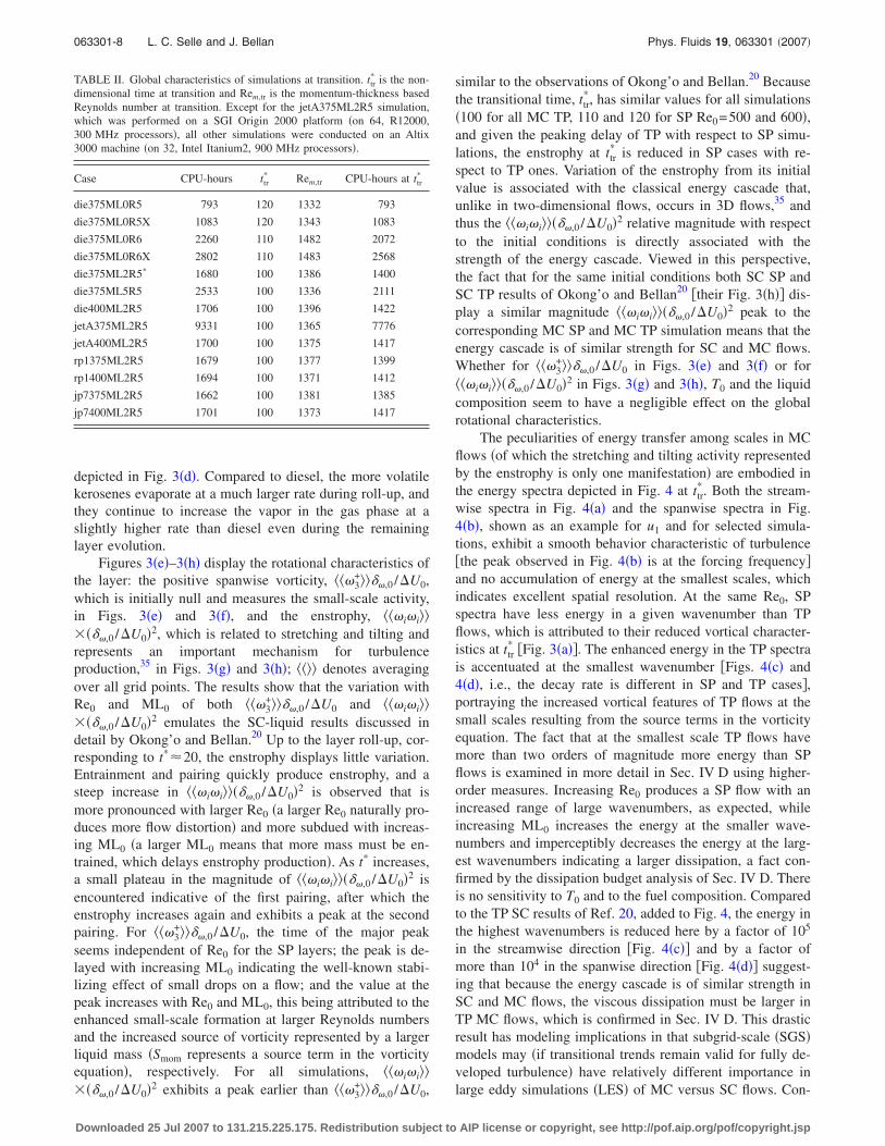
The peculiarities of energy transfer among scales in MCflows �of which the stretching and tilting activity representedby the enstrophy is only one manifestation� are embodied inthe energy spectra depicted in Fig. 4 at ttr
*. Both the stream-wise spectra in Fig. 4�a� and the spanwise spectra in Fig.4�b�, shown as an example for u1 and for selected simula-tions, exhibit a smooth behavior characteristic of turbulence�the peak observed in Fig. 4�b� is at the forcing frequency�and no accumulation of energy at the smallest scales, whichindicates excellent spatial resolution. At the same Re0, SPspectra have less energy in a given wavenumber than TPflows, which is attributed to their reduced vortical character-istics at ttr
* �Fig. 3�a��. The enhanced energy in the TP spectrais accentuated at the smallest wavenumber �Figs. 4�c� and4�d�, i.e., the decay rate is different in SP and TP cases�,portraying the increased vortical features of TP flows at thesmall scales resulting from the source terms in the vorticityequation. The fact that at the smallest scale TP flows havemore than two orders of magnitude more energy than SPflows is examined in more detail in Sec. IV D using higher-order measures. Increasing Re0 produces a SP flow with anincreased range of large wavenumbers, as expected, whileincreasing ML0 increases the energy at the smaller wave-numbers and imperceptibly decreases the energy at the larg-est wavenumbers indicating a larger dissipation, a fact con-firmed by the dissipation budget analysis of Sec. IV D. Thereis no sensitivity to T0 and to the fuel composition. Comparedto the TP SC results of Ref. 20, added to Fig. 4, the energy inthe highest wavenumbers is reduced here by a factor of 105
in the streamwise direction �Fig. 4�c�� and by a factor ofmore than 104 in the spanwise direction �Fig. 4�d�� suggest-ing that because the energy cascade is of similar strength inSC and MC flows, the viscous dissipation must be larger inTP MC flows, which is confirmed in Sec. IV D. This drasticresult has modeling implications in that subgrid-scale �SGS�models may �if transitional trends remain valid for fully de-veloped turbulence� have relatively different importance inlarge eddy simulations �LES� of MC versus SC flows. Con-
TABLE II. Global characteristics of simulations at transition. ttr* is the non-
dimensional time at transition and Rem,tr is the momentum-thickness basedReynolds number at transition. Except for the jetA375ML2R5 simulation,which was performed on a SGI Origin 2000 platform �on 64, R12000,300 MHz processors�, all other simulations were conducted on an Altix3000 machine �on 32, Intel Itanium2, 900 MHz processors�.
Case CPU-hours ttr* Rem,tr CPU-hours at ttr
*
die375ML0R5 793 120 1332 793
die375ML0R5X 1083 120 1343 1083
die375ML0R6 2260 110 1482 2072
die375ML0R6X 2802 110 1483 2568
die375ML2R5* 1680 100 1386 1400
die375ML5R5 2533 100 1336 2111
die400ML2R5 1706 100 1396 1422
jetA375ML2R5 9331 100 1365 7776
jetA400ML2R5 1700 100 1375 1417
rp1375ML2R5 1679 100 1377 1399
rp1400ML2R5 1694 100 1371 1412
jp7375ML2R5 1662 100 1381 1385
jp7400ML2R5 1701 100 1373 1417
063301-8 L. C. Selle and J. Bellan Phys. Fluids 19, 063301 �2007�
Downloaded 25 Jul 2007 to 131.215.225.175. Redistribution subject to AIP license or copyright, see http://pof.aip.org/pof/copyright.jsp
sidering the lack of energy accumulation at the smallestscales in Fig. 4, confidence that the qualitative nature of theabove results is independent of our grid size is provided bythe grid resolution studies of Vreman,36 in which simulationson three different grids provided the relevant flow propertieswithin 2% deviation across grids for an Eulerian-Lagrangianmodel similar to ours.
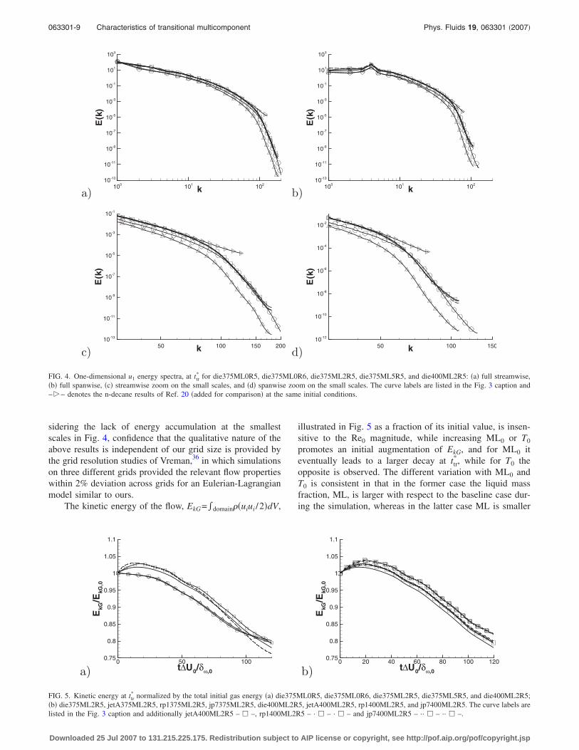
The kinetic energy of the flow, EkG=�domain��uiui /2�dV,
illustrated in Fig. 5 as a fraction of its initial value, is insen-sitive to the Re0 magnitude, while increasing ML0 or T0
promotes an initial augmentation of EkG, and for ML0 iteventually leads to a larger decay at ttr
*, while for T0 theopposite is observed. The different variation with ML0 andT0 is consistent in that in the former case the liquid massfraction, ML, is larger with respect to the baseline case dur-ing the simulation, whereas in the latter case ML is smaller
a) k
E(k
)
100 101 10210-13
10-11
10-9
10-7
10-5
10-3
10-1
101
103
b) k
E(k
)
100 101 10210-13
10-11
10-9
10-7
10-5
10-3
10-1
101
103
c) k
E(k
)
50 100 150 20010-13
10-11
10-9
10-7
10-5
10-3
10-1
d) k
E(k
)
50 100 15010-12
10-10
10-8
10-6
10-4
10-2
FIG. 4. One-dimensional u1 energy spectra, at ttr* for die375ML0R5, die375ML0R6, die375ML2R5, die375ML5R5, and die400ML2R5: �a� full streamwise,
�b� full spanwise, �c� streamwise zoom on the small scales, and �d� spanwise zoom on the small scales. The curve labels are listed in the Fig. 3 caption and−�− denotes the n-decane results of Ref. 20 �added for comparison� at the same initial conditions.
a) t∆U0/δω,0
EkG
/EkG
,0
0 50 1000.75
0.8
0.85
0.9
0.95
1
1.05
1.1
b) t∆U0/δω,0
EkG
/EkG
,0
0 20 40 60 80 100 1200.75
0.8
0.85
0.9
0.95
1
1.05
1.1
FIG. 5. Kinetic energy at ttr* normalized by the total initial gas energy �a� die375ML0R5, die375ML0R6, die375ML2R5, die375ML5R5, and die400ML2R5;
�b� die375ML2R5, jetA375ML2R5, rp1375ML2R5, jp7375ML2R5, die400ML2R5, jetA400ML2R5, rp1400ML2R5, and jp7400ML2R5. The curve labels arelisted in the Fig. 3 caption and additionally jetA400ML2R5 – � –, rp1400ML2R5 – · � – · � – and jp7400ML2R5 – ·· � – ·· � –.
063301-9 Characteristics of transitional multicomponent Phys. Fluids 19, 063301 �2007�
Downloaded 25 Jul 2007 to 131.215.225.175. Redistribution subject to AIP license or copyright, see http://pof.aip.org/pof/copyright.jsp
due to the larger evaporation. Liquid composition effectsshown in Fig. 5�b� are as strong as the ML0 or T0 effects.With increasing liquid volatility, EkG /EkG,0 increases, emu-lating the increased T0 effect, and the rate of decay is slightlyreduced, consistent with the dissipation budget discussed inSec. IV D. At T0=375 K the effect is small, and similar plotsat T0=400 K exhibit a slightly larger difference betweenliquids.
The results show that experiments conducted for MCmodel validation purposes, none of which currently exist,should not focus on global characteristics of the flow, withthe exception of MG /MG,0, because they are not sensitive tothe liquid composition.
2. Drop characteristics
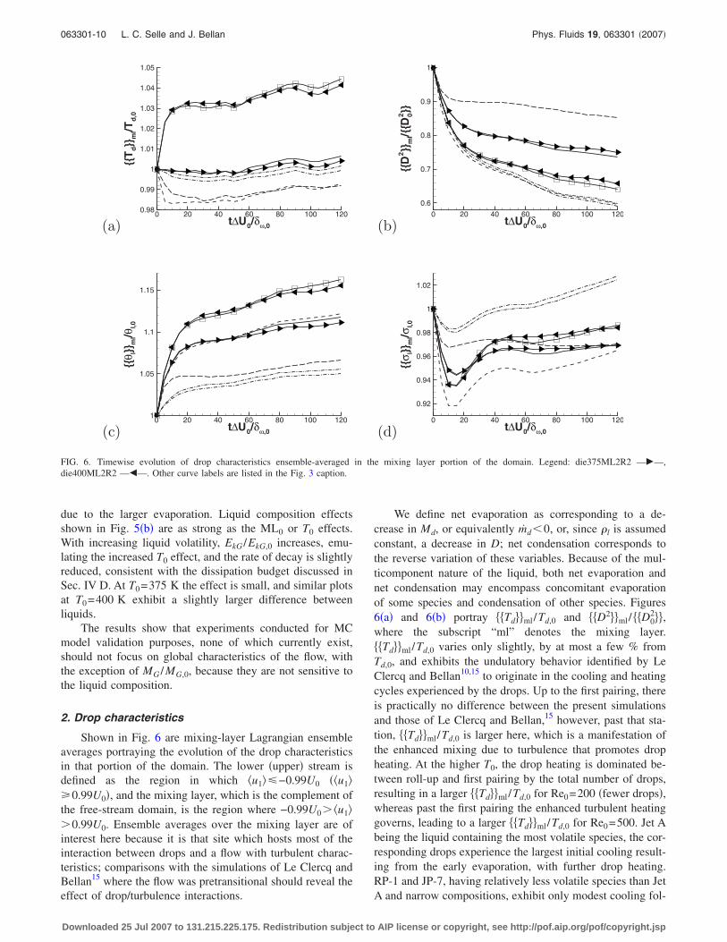
Shown in Fig. 6 are mixing-layer Lagrangian ensembleaverages portraying the evolution of the drop characteristicsin that portion of the domain. The lower �upper� stream isdefined as the region in which �u1��−0.99U0 ��u1��0.99U0�, and the mixing layer, which is the complement ofthe free-stream domain, is the region where −0.99U0� �u1��0.99U0. Ensemble averages over the mixing layer are ofinterest here because it is that site which hosts most of theinteraction between drops and a flow with turbulent charac-teristics; comparisons with the simulations of Le Clercq andBellan15 where the flow was pretransitional should reveal theeffect of drop/turbulence interactions.
We define net evaporation as corresponding to a de-crease in Md, or equivalently md�0, or, since �l is assumedconstant, a decrease in D; net condensation corresponds tothe reverse variation of these variables. Because of the mul-ticomponent nature of the liquid, both net evaporation andnet condensation may encompass concomitant evaporationof some species and condensation of other species. Figures6�a� and 6�b� portray Td��ml/Td,0 and D2��ml/ D0
2��,where the subscript “ml” denotes the mixing layer. Td��ml/Td,0 varies only slightly, by at most a few % fromTd,0, and exhibits the undulatory behavior identified by LeClercq and Bellan10,15 to originate in the cooling and heatingcycles experienced by the drops. Up to the first pairing, thereis practically no difference between the present simulationsand those of Le Clercq and Bellan,15 however, past that sta-tion, Td��ml/Td,0 is larger here, which is a manifestation ofthe enhanced mixing due to turbulence that promotes dropheating. At the higher T0, the drop heating is dominated be-tween roll-up and first pairing by the total number of drops,resulting in a larger Td��ml/Td,0 for Re0=200 �fewer drops�,whereas past the first pairing the enhanced turbulent heatinggoverns, leading to a larger Td��ml/Td,0 for Re0=500. Jet Abeing the liquid containing the most volatile species, the cor-responding drops experience the largest initial cooling result-ing from the early evaporation, with further drop heating.RP-1 and JP-7, having relatively less volatile species than JetA and narrow compositions, exhibit only modest cooling fol-
(a) t∆U0/δω,0
{{T
d}}
ml/T
d,0
0 20 40 60 80 100 1200.98
0.99
1
1.01
1.02
1.03
1.04
1.05
(b) t∆U0/δω,0
{{D
2}}
ml/{
{D2 0}}
0 20 40 60 80 100 120
0.6
0.7
0.8
0.9
1
(c) t∆U0/δω,0
{{θ l}}
ml/θ
l,0
0 20 40 60 80 100 1201
1.05
1.1
1.15
(d) t∆U0/δω,0
{{σ l}}
ml/σ
l,0
0 20 40 60 80 100 120
0.92
0.94
0.96
0.98
1
1.02
FIG. 6. Timewise evolution of drop characteristics ensemble-averaged in the mixing layer portion of the domain. Legend: die375ML2R2 —�—,die400ML2R2 —�—. Other curve labels are listed in the Fig. 3 caption.
063301-10 L. C. Selle and J. Bellan Phys. Fluids 19, 063301 �2007�
Downloaded 25 Jul 2007 to 131.215.225.175. Redistribution subject to AIP license or copyright, see http://pof.aip.org/pof/copyright.jsp

lowed by heating, and the slightly more volatile species inRP-1 lead to a slightly increased cooling with respect toJP-7. A larger ML0 manifests in an enhanced drop coolingthat rivals for diesel at ML0=0.5 the cooling experienced byJet A. For all liquids, however, the small variations in Td��ml/Td,0 translate in considerably larger variations in D2��ml/ D0
2��, with the rapid initial temperature changecorresponding to the steepest decrease in the drop size,which subsides by the end of roll-up. An intermediary rate ofevaporation follows that abates by the middle of the secondpairing, upon reaching a very gradual drop reduction. Thenonconstant rate of D2��ml/ D0
2�� decay is a mark of theensemble averaging, as each individual drop obeys the clas-sical D2 law.14 On going from pretransitional to transitionalflow results, one notes an eventual reduction in D2��ml/ D0
2�� by �5% �Vd by �11%�. Kerosene dropsreach by the end of the simulation �46% of Vd,0 comparedto diesel’s �63%, and an increase in mass loading of a factorof 2.5 leads to a factor of �1.7 increase in Vd by the end ofthe computation. Clearly, within the range of parameters in-vestigated, the fuel identity is the most prominent factor in-fluencing the drop size evolution.
Companion plots of �l��ml/�l,0 and �l��ml/�l,0 are dis-played in Figs. 6�c� and 6�d�. As in results portraying entire-domain ensemble averages from simulations of Le Clercqand Bellan,15 the initial �l��ml/�l,0 surge is accompanied bya drastic reduction in �l��ml/�l,0 as the most volatile spe-cies evaporate, thus reducing the number of species in thedrop. Eventually �l��ml/�l,0 reaches a minimum that coin-cides with a tapering off in the augmentation of �l��ml/�l,0.The interaction of drops with the flow promotes evaporation/condensation, and thus enhances changes in both �l��ml/�l,0
and �l��ml/�l,0. The augmentation in �l��ml/�l,0 indicatesthat condensation occurs, with a local plateau evident by theend of the first pairing; the concomitant increase in �l��ml/�l,0 indicates that, on an ensemble basis, evaporationis more effective than condensation in determining the meanliquid molar mass. Up to the first pairing there is no sensi-tivity to Re0, however, once small scales become preponder-ant �Figs. 3�g� and 3�h��, one can detect not only quantitativebut also qualitative differences between the pretransitionaland transitional results; although �l��ml/�l,0 continues to in-crease in both cases, being larger in the latter situation, �l��ml/�l,0 for transitional computations reaches a mini-mum, then increases, and eventually crosses over the everincreasing �l��ml/�l,0 at Re0=200. The decrease in �l��ml/�l,0 corresponds to a narrower DGPDF, and repre-sents the accelerated release of species due to the drop/turbulence interaction. Eventually, the species evaporationbecomes limited by the value of Td while species condensa-tion again augments �l��ml/�l,0. The lack of �l��ml/�l,0
and �l��ml/�l,0 variation in tandem as a function of Re0
means that the pretransitional simulations do not merely rep-resent an intermediary state to the transitional results becausenot only is the mean molar mass larger here, but the entirecomposition distribution is different due to the simultaneousevaporation and condensation of different species promotedby the turbulent flow transporting drops to various sites ofthe layer. For all liquids at the baseline conditions,
�l��ml/�l,0 continuously increases with t* as evaporation de-pletes increasingly less volatile species, but the rate of aug-mentation is not uniform even after the initial surge. Thisnonuniform rate is consistent with the nonmonotonic evolu-tion of �l��ml/�l,0 representing evaporation when it de-creases and condensation when it increases. At the largerML0, �l��ml/�l,0 no longer increases monotonically and in-stead experiences a minimum about halfway through the firstpairing while �l��ml/�l,0 displays a maximum at the firstpairing; that is, the reduction in Td at the larger ML0 resultsin decreasing evaporation, which, combined with the con-densation of the lighter species, reduces the mean molarmass and further increases the width of the composition dis-tribution. Clearly, as ML0 increases, evaporation becomesgoverned by limitations in drop heating rather than by thedrop/turbulence interaction. At the larger T0, the larger�smaller� �l��ml/�l,0 for Re0=200 than for Re0=500 be-tween roll-up and first pairing �after the first pairing� corre-sponds to the higher �lower� Td��ml/Td,0.
It is noteworthy that, except for the liquids with the nar-rowest composition PDF �i.e. RP-1 and JP-7�, �l��ml/�l,0
does not exceed unity. That is, drops of liquids with a nar-rower composition are more prone to larger changes in thewidth of their composition distribution as each condensingspecies onto a drop makes a larger impact on the composi-tion of the liquid drop. When the liquid composition has aPDF with a larger width, evaporation of species of ever de-creasing volatility dominates the condensation of the lighterspecies within the time span of these simulations, resulting ina reduced composition heterogeneity.
Not surprisingly, the drop size and composition are goodmetrics to distinguish between various fuels and thus futureexperiments geared at model validation should strive to mea-sure these quantities.
3. Vapor composition characteristics
The effect of Re0 and ML0 on the vapor composition isillustrated in Figs. 7�a� and 7�c�, and the influence of liquididentity and T0 is depicted in Figs. 7�b� and 7�d�. Parallelingthe drop ensemble averages of Fig. 6, the volumetric aver-ages of Fig. 7 are also over the mixing layer portion of thedomain. It is noteworthy that the simulation provides onlythe first four moments of the vapor composition, but not themathematical form of its PDF. Indeed, consistent with thecalculation of the source terms at grid nodes, the vapor-composition PDF is at each node the sum, according to Eq.�19�, of all vapor PDFs at the drop surface for drops locatedwithin the grid volume associated with the specified node.The summation of DGPDFs having different values of same-order moments is not necessarily a DGPDF. Only the firsttwo moments of the composition are examined in Fig. 7. ThePDF representation of the vapor composition, including thehigher moments, is addressed in Sec. IV E.
For diesel, independent of the initial conditions,���v��ml/�v,0 experiences a sustained growth from unity, ini-tially representing the combined effect of condensation oflighter species onto drops, as is obvious from the sharp decayin ���v��ml/�v,0, and of species heavier than �v,0 that may
063301-11 Characteristics of transitional multicomponent Phys. Fluids 19, 063301 �2007�
Downloaded 25 Jul 2007 to 131.215.225.175. Redistribution subject to AIP license or copyright, see http://pof.aip.org/pof/copyright.jsp

have been released through drop evaporation. Further in-crease in ���v��ml/�v,0 is accompanied by an augmentation in���v��ml/�v,0, showing that although evaporation of somespecies occurs concomitantly with condensation of other spe-cies, during the remainder of the simulation it is species ad-dition from the liquid phase that dominates the changes inthe vapor composition. In contrast, the kerosenes experiencean immediate increase in ���v��ml/�v,0 due to evaporation, as���v��ml/�v,0 simultaneously increases. Compared to achange in Re0 by a factor of 2.5, a change by the same factorin ML0 produces a much larger effect on ���v��ml/�v,0 and���v��ml/�v,0. The much reduced ���v��ml/�v,0 obtained whenML0=0.5 results from the increased condensation detectedin Fig. 7�c�, reflecting drop-heating relative impediments,and is consistent with the lower Td��ml/Td,0 in Fig. 6�a�.The larger initial decay experienced by ���v��ml/�v,0 at thelower Re0 �Fig. 7�c�� shows that relative to the higher Re0, alarger number of species condenses and because the con-densing species have a smaller molar mass, this process pro-duces a higher ���v��ml/�v,0 from roll-up to the first pairing�Fig. 7�a��. Past the first pairing, the larger Td��ml/Td,0 atthe higher Re0 �Fig. 6�a�� leads to increasing evaporationversus condensation which augments ���v��ml/�v,0 and el-evates ���v��ml/�v,0 through the addition of higher molarmass species.
Mirroring the drop composition characteristics, changesin the vapor composition are smallest for the narrowestcomposition-PDF kerosenes for which the vapor mean molarmass increases �Fig. 7�b�� owing to net evaporation �Fig.7�d��; T0 has only a very modest effect as the species ther-modynamics are quite similar for the narrow compositions.Although initial net evaporation also increases ���v��ml/�v,0
for Jet A, its much wider composition PDF leads to a corre-spondingly greater T0 impact. Finally, as already discussed,diesel is distinct from all other liquids in that the augmenta-tion of ���v��ml/�v,0 is initially due to condensation of lightervapor species onto the drops and also to evaporation ofheavier species from the drops, and its much wider compo-sition PDF makes it prone to the largest influence of T0.
It is noteworthy that the value of ���v�� /�v,0 has a theo-retical maximum limit corresponding to complete dropevaporation. Neglecting the initial amount of vapor �whichhere represents less than 0.53% of the total liquid mass�, ifall liquid were evaporated, the composition of the vaporwould be that of the liquid at t*=0, that is,max����v�� /�v,0�=�l,0 /�v,0. From Table I one finds that�l,0 /�v,0 is 1.32 for diesel, 1.23 for Jet A, 1.076 for RP-1, and1.087 for JP-7. The departure of ���v�� /�v,0 from theseasymptotic limits depends on the amount of vapor alreadyreleased. The impact of T0 is only on the evaporation rate,
(a) t∆U0/δω,0
<<
θ v>>
ml/θ
v,0
0 20 40 60 80 100 1201
1.05
1.1
1.15
(b) t∆U0/δω,0
<<
θ v>>
ml/θ
v,0
0 20 40 60 80 100 1201
1.05
1.1
1.15
(c) t∆U0/δω,0
<<
σ v>>
ml/σ
v,0
0 20 40 60 80 100 1200.9
0.95
1
1.05
1.1
1.15
(d) t∆U0/δω,0
<<
σ v>>
ml/σ
v,0
0 20 40 60 80 100 1200.9
0.95
1
1.05
1.1
1.15
FIG. 7. Timewise evolution of domain-averaged gas characteristics in the mixing layer. ��a� and �c�� die375ML2R2, die375ML2R5, and die375ML5R5; and��b� and �d�� die375ML2R5, die400ML2R5, jetA375ML2R5, jetA400ML2R5, rp1375ML2R5, rp1400ML2R5, jp7375ML2R5, and jp7400ML2R5. Curvelabels are listed in the Figs. 3, 6, and 5 captions.
063301-12 L. C. Selle and J. Bellan Phys. Fluids 19, 063301 �2007�
Downloaded 25 Jul 2007 to 131.215.225.175. Redistribution subject to AIP license or copyright, see http://pof.aip.org/pof/copyright.jsp

and thus on the time needed to reach this asymptotic value.Consequently, the bunching in Fig. 7�b� of ���v�� /�v,0 forRP-1 and JP-7 is consistent with their similar values of�l,0 /�v,0 and evaporation rates �Fig. 6�b��, and curves for JetA and diesel match by happenstance as a result of the com-peting effects between the significantly higher asymptoticlimit for diesel and the much higher evaporation rate for JetA �Fig. 6�b��. These considerations are independent of theactual composition of the initial vapor; however, because theinitial vapor is found here from a single-drop simulation inair at the specified T0 �by choosing it to be the first-time-stepsurface-vapor composition�, this means that �v,0 depends on�l,0 through the width of the liquid-PDF, finally explainingwhy RP-1 and JP-7 on the one hand and diesel and Jet A onthe other hand show similar ���v�� /�v,0.
Clearly, averaged quantities can only give a generalphysical picture of the flow, and detailed visualizations, pre-sented next, are necessary to understand the details of thesituation.
B. Flow visualizations
1. Drop field
The detailed distribution of the drop number density, �n,calculated as an Eulerian field from the Lagrangian distribu-tion
�n = �q=1
Nd wq
�Vq�22�
is presented in Fig. 8. The plots depict the between-the-braidplane x3 /L3=0.5 for selected simulations, each at ttr
*. Allsimulations display an intricate drop organization exhibitinga multitude of scales. The void regions correspond to loca-tions of high vorticity37 and contain no drops as the �n valuebased on one drop per computational volume leads to �n
=5.9�109 m−3. The outline of the void regions correspondsto high-strain locations �Ref. 37; also see Sec. IV C 1� anddisplays large concentrations of drops.
Increasing ML0 �Figs. 8�a� and 8�c�� leads to a moreintricate drop organization exhibiting a larger range ofscales; this is because at the same St0 value, the larger N0
induces more drop/flow interaction, which amplifies localnonuniformities through the drag action. The larger ML0
leads expectably to higher �n values.With increasing T0, diesel �Figs. 8�a� and 8�b�� and JP-7
�Figs. 8�g� and 8�h�� exhibit more heterogeneity in the lowerstream and part of the mixing layer, with void regions thatnow punctuate the rather uniform �n lower stream. Thesenew regions of small �n result from the enhanced drop heat-ing, which promotes evaporation. No such regions are de-tected for Jet A �Figs. 8�e� and 8�f�� within the range ofdisplayed �n, although structural changes with increasing T0
are clearly visible. This dependency of the drop organizationon T0 should be contrasted with the insensitivity to T0 foundin the pretransitional simulations of Le Clercq and Bellan.15
It is thus clear that the coupling between turbulence anddrops creates this T0 dependency.
Composition effects, examined at both T0=375 K �Figs.8�a�, 8�e�, and 8�g�� and 400 K �Figs. 8�b�, 8�d�, 8�e�, and8�h��, show that the complexity of the drop organization de-creases with increased fuel volatility, indicating that by re-ducing the drop size and thus the local drop/flow drag force,early evaporation has a homogenizing effect on the �n struc-ture. Because at T0=400 K all kerosenes have the same N0
and D0�� �see Table I�, the different �n distributions por-trayed in Figs. 8�b�, 8�d�, 8�e�, and 8�h� result solely from thedifferent liquid composition. The global structural organiza-tion for RP-1 and JP-7 �which have similar compositionPDFs� at the same initial conditions is virtually identical,although local differences in the structure of the field andvalue of �n are visible.
Additional insight into the relationship between the dropposition, its temperature, and its composition is achieved byexamining Lagrangian visualizations displayed in Fig. 9 forthe baseline case at ttr
* in the mixing layer portion of thedomain; each sphere in the plot represents a physical drop,the drops are magnified for readability, and there is no rela-tionship between a drop size and its plotted volume. Due tothe viewing angle, the void regions evident in Fig. 8 areobscured. The lower part of the mixing layer is populated bylow-Td drops �Fig. 9�a��, but as the drops penetrate furtherinto the mixing layer, they heat up and form temperature-wise a very heterogeneous drop ensemble. The largest Td isachieved by drops located at the top of the ultimate vortex,as they are in contact with the upper stream carrier gas at T0.The impact of Td on �l is evident in Fig. 9�b�. Both the drophistory and its instantaneous Td determine the value of �l, asnot all drops within a given temperature range have the samecomposition. The drops with the smallest �l are located in thelower part of the mixing layer, and their �l is noticeablyhigher than �l,0 owing to the already evaporated volatiles.The mixing layer contains drops with a great variety of com-positions and the composition diversity is also obvious in theremnant of the initial four spanwise vortices; a quantitativemeasure of the heterogeneous distribution is presented inSec. IV C 1. Drops having �l�245 kg/kmol are primarilylocated at the top of the ultimate vortex. However, not alldrops at that location have �l�245 kg/kmol, as most dropsthere have 235 kg/kmol��l�245 kg/kmol. Moreover,some drops with 235 kg/kmol��l�245 kg/kmol are alsofound embedded deep in the lower part of the ultimate vor-tex. This substantial local variation in �l is premonitory ofwhat could be expected for �v.
2. Flow fielda. Dynamics. To differentiate between SP and TP simu-
lations, the between-the-braid plane �3��,0 /�U0 is first dis-played in Fig. 10 for all ML0=0 computations. In all cases,the complex structure of the flow is apparent with regions ofnegative values, as in the initial condition, interspersed withregions of substantial positive values that are a manifestationof the developed small-scale activity. The maximum�3��,0 /�U0 value increases with Re0, as expected, and de-creases with increasing �Xv,0
l −Xv,0u �, which is attributed to the
correspondingly increasing scalar dissipation, a fact con-firmed in Sec. IV D. The increased scalar dissipation contrib-
063301-13 Characteristics of transitional multicomponent Phys. Fluids 19, 063301 �2007�
Downloaded 25 Jul 2007 to 131.215.225.175. Redistribution subject to AIP license or copyright, see http://pof.aip.org/pof/copyright.jsp

utes to the larger dissipation, and due to the coupling of thedynamics with scalar transport, the viscous dissipationwhose role is the reduction of organized motion also in-creases �Sec. IV D�, which decreases the vorticity.
The ML0�0 spanwise vorticity is illustrated in Fig. 11
for the same simulations shown in Fig. 8. The maximum�3��,0 /�U0 value increases with increasing ML0 when go-ing from null to non-null values �compare with Fig. 10�a��but the opposite occurs when ML0 changes from 0.2 to 0.5,and instead concentrated regions of high vorticity appear,
FIG. 8. Drop number density �m−3� in the between-the-braid plane �x3 /L3=0.5� at ttr*: �a� die375ML2R5, �b� die400ML2R5, �c� die375ML5R5, �d�
rp1400ML2R5, �e� jetA375ML2R5, �f� jetA400ML2R5, �g� jp7375ML2R5, and �h� jp7400ML2R5.
063301-14 L. C. Selle and J. Bellan Phys. Fluids 19, 063301 �2007�
Downloaded 25 Jul 2007 to 131.215.225.175. Redistribution subject to AIP license or copyright, see http://pof.aip.org/pof/copyright.jsp
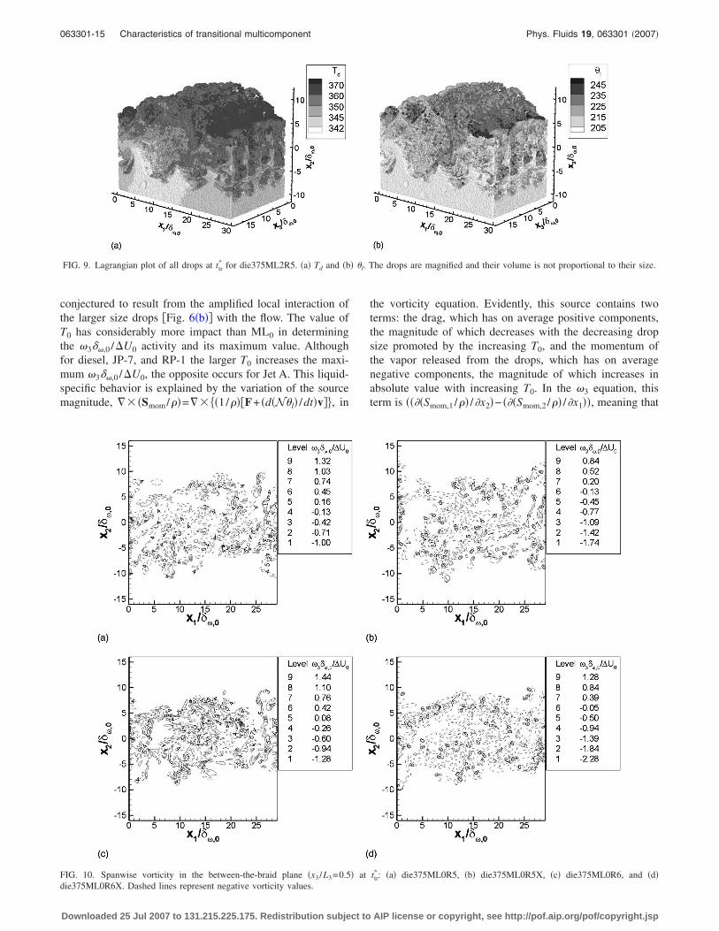
conjectured to result from the amplified local interaction ofthe larger size drops �Fig. 6�b�� with the flow. The value ofT0 has considerably more impact than ML0 in determiningthe �3��,0 /�U0 activity and its maximum value. Althoughfor diesel, JP-7, and RP-1 the larger T0 increases the maxi-mum �3��,0 /�U0, the opposite occurs for Jet A. This liquid-specific behavior is explained by the variation of the sourcemagnitude, �� �Smom/��=�� �1/���F+ �d�N�l� /dt�v��, in
the vorticity equation. Evidently, this source contains twoterms: the drag, which has on average positive components,the magnitude of which decreases with the decreasing dropsize promoted by the increasing T0, and the momentum ofthe vapor released from the drops, which has on averagenegative components, the magnitude of which increases inabsolute value with increasing T0. In the �3 equation, thisterm is ����Smom,1 /�� /�x2�− ���Smom,2 /�� /�x1��, meaning that
FIG. 9. Lagrangian plot of all drops at ttr* for die375ML2R5. �a� Td and �b� �l. The drops are magnified and their volume is not proportional to their size.
FIG. 10. Spanwise vorticity in the between-the-braid plane �x3 /L3=0.5� at ttr*: �a� die375ML0R5, �b� die375ML0R5X, �c� die375ML0R6, and �d�
die375ML0R6X. Dashed lines represent negative vorticity values.
063301-15 Characteristics of transitional multicomponent Phys. Fluids 19, 063301 �2007�
Downloaded 25 Jul 2007 to 131.215.225.175. Redistribution subject to AIP license or copyright, see http://pof.aip.org/pof/copyright.jsp

FIG. 11. Spanwise vorticity in the x3 /L3=0.5 plane at ttr*: �a� die375ML2R5, �b� die400ML2R5, �c� die375ML5R5, �d� rp1400ML2R5, �e� jetA375ML2R5,
�f� jetA400ML2R5, �g� jp7375ML2R5, and �h� jp7400ML2R5. Dashed lines represent negative vorticity values.
063301-16 L. C. Selle and J. Bellan Phys. Fluids 19, 063301 �2007�
Downloaded 25 Jul 2007 to 131.215.225.175. Redistribution subject to AIP license or copyright, see http://pof.aip.org/pof/copyright.jsp

it is not only the sign of each of the two contributions that isimportant, but also their spatial variation that influences thesign of the source term. Although a direct relationship be-tween liquid volatility and the sign of the source term is notimmediately apparent, we note that for a very volatile liquidsuch as Jet A, ��� �Smom/���3 evidently becomes smallerwith increasing T0, whereas for a relatively much less vola-tile liquid, such as diesel, the vorticity source term becomeslarger with increasing T0. Because JP-7 and RP-1 follow thediesel trend, what seems to be the determining factor in thisvariation is the lightest species entering the composition ofthe liquid �see Fig. 2� rather than the width of the composi-tion PDF. This T0 effect on the vortical activity should becontrasted to the insensitivity observed in the pretransitionalsimulations of Le Clercq and Bellan,15 indicating that thisaspect is intimately related to the turbulence productionthrough the drop/flow interaction.
b. Thermodynamics. The Yv contours are shown in Fig.12 for the same simulations illustrated in Fig. 8. The hetero-geneity of the vapor distribution is noteworthy in all cases,with the larger values generally confined to the lower stream.As either T0 or ML0 increases �Figs. 12�a�–12�c��, the maxi-mum Yv increases, but this effect is a much stronger functionof T0 than of ML0 because an augmentation in T0 promotessingle-drop evaporation through enhanced heat transfer,whereas the opposite happens at a more elevated ML0 due tolimitations on heat transfer from a gas phase with a fixedamount of heat. The larger maximum Yv at ML0=0.5 com-pared to ML0=0.2 is thus a consequence of N0, which affectsNm. Examination of the Yv field structure shows increasedheterogeneity with increasing T0 or ML0, with regions of thelargest Yv penetrating well into the mixing layer and reach-ing its boundary adjacent to the upper stream while pocketsof negligible Yv embed deep into the mixing layer. Concomi-tantly, regions of low Yv are now present as isolated pocketsin the lower stream. At fixed T0 and ML0, the maximum Yvincreases with increasing fuel volatility, while the structuralcomplexity of the Yv field decreases, which is attributed tothe earlier evaporation that allows substantial small-scalemixing before the achievement of transition.
To entirely characterize the vapor, composition contoursare displayed for �v in Fig. 13 and for �v in Fig. 14 corre-sponding to the simulations presented in Fig. 12. Comparedto the pretransitional results of Le Clercq and Bellan,15 the �vcontours are considerably more contorted, with multiple lo-cations, rather than a single location, of very high valuesthroughout the mixing layer. With increasing T0, the maxi-mum value of �v increases �Figs. 13�a� and 13�b�; Figs. 13�g�and 13�h�� due to the evaporation of the heavier components;the opposite occurs when ML0 increases �Figs. 13�a� and13�c�� due to the limitation in heat transfer, which preventsthe release of heavier components. Generally, the range of �vvalues mirrors that in the initial liquid composition �Fig. 2�in that a narrow initial PDF range translates into a narrowrange of �v values. For a narrower initial PDF having alarger-m component as its most volatile species �e.g., JP-7,for which �=93 kg/kmol, shown in Fig. 13�g� relative todiesel, for which �=86 kg/kmol, shown in Fig. 13�a��, thelower stream is uniquely composed of very light species due
to the larger time lag necessary for the drops to reach a Td
value at which evaporation may proceed; at the more el-evated ML0, �v is also smaller in the lower stream, this beingattributed to the lower Td, which hinders evaporation of rela-tively less volatile species. The very close association be-tween initial liquid composition and the magnitude and dis-tribution of �v is best highlighted when examining Figs.13�d� and 13�h� representing RP-1 and JP-7 at the same con-ditions: their almost coincidental PDFs of Fig. 2 results invirtually the same contour distribution and magnitude.Whether at T0=375 K �Figs. 13�a�, 13�e�, and 13�g�� or atT0=400 K �Figs. 13�b�, 13�d�, 13�f�, and 13�h��, the hetero-geneity of the �v distribution increases with decreasing PDFwidth.
Parallel contour plots of �v add more details to the in-formation on the vapor composition. For all simulations, �vdisplays a complex distribution with generally small valuesin either stream, and intermediate and high values confinedto the mixing layer. Notable exceptions are the baseline die-sel simulation �Fig. 14�a�� and that with ML0=0.5 �Fig.14�c��, where the upper stream exhibits larger �v than thelower stream, this being a manifestation of the lower streamcondensation rather than implying that the upper stream �v isheterogeneous. Whereas in the pretransitional study of LeClercq and Bellan15 the locations of maximum �v and �ventirely coincided, here this is no longer the case. Althoughthe intersection of the maximum-value �v and �v locations isnot null in corresponding plots of Figs. 13 and 14, there is aconsiderable number of locations of maximum �v value thatdo not correspond to a location of maximum �v value, andvice versa. After substantial evaporation, when only theheavier species remain in a drop, the evolved turbulence isresponsible for transporting that drop in regions where thevapor composition may be relatively uniform, and thus thelocal drop evaporation will result at that location in a large �vbut relatively small �v �e.g., Figs. 13�a�, 13�e�, and 13�g�compared to Figs. 14�a�, 14�e�, and 14�g�, respectively�.Conversely, drops at intermediary stages of evaporation maybe brought by turbulence in a region of strong compositionnonuniformity, thereby creating through evaporation a loca-tion of intermediary �v values and high �v values �i.e., Fig.13�f� compared to Fig. 14�f��. Scrutiny of Figs. 14�d� and14�f� makes it clear that, unlike for �v, here there is no longeras strong a relationship between the initial liquid-composition PDF and the �v magnitude, although the quali-tative aspect and the relative structure of the �v distributionare still closely related to this PDF. Increasing T0 �Figs. 14�a�and 14�b�, Figs. 14�e� and 14�f�, and Figs. 14�g� and 14�h��results in the maximum �v increasing, and this effect isstronger with decreased fuel volatility �diesel versus all kero-senes� because this promotes the release of an increasingrange of heavier components from drops, as seen when com-paring Figs. 13�a� and 13�b�.
The general picture that emerges is that of the impor-tance of both drop/turbulent-flow interaction and initialliquid-composition PDF in determining the vapor distribu-tion and local composition. Both T0 and ML0 couple nonlin-early with that interaction and with the initial liquid-composition PDF.
063301-17 Characteristics of transitional multicomponent Phys. Fluids 19, 063301 �2007�
Downloaded 25 Jul 2007 to 131.215.225.175. Redistribution subject to AIP license or copyright, see http://pof.aip.org/pof/copyright.jsp

FIG. 12. �Color� Vapor mass fraction in the between-the-braid plane �x3 /L3=0.5� at ttr*: �a� die375ML2R5, �b� die400ML2R5, �c� die375ML5R5, �d�
rp1400ML2R5, �e� jetA375ML2R5, �f� jetA400ML2R5, �g� jp7375ML2R5, and �h� jp7400ML2R5.
063301-18 L. C. Selle and J. Bellan Phys. Fluids 19, 063301 �2007�
Downloaded 25 Jul 2007 to 131.215.225.175. Redistribution subject to AIP license or copyright, see http://pof.aip.org/pof/copyright.jsp
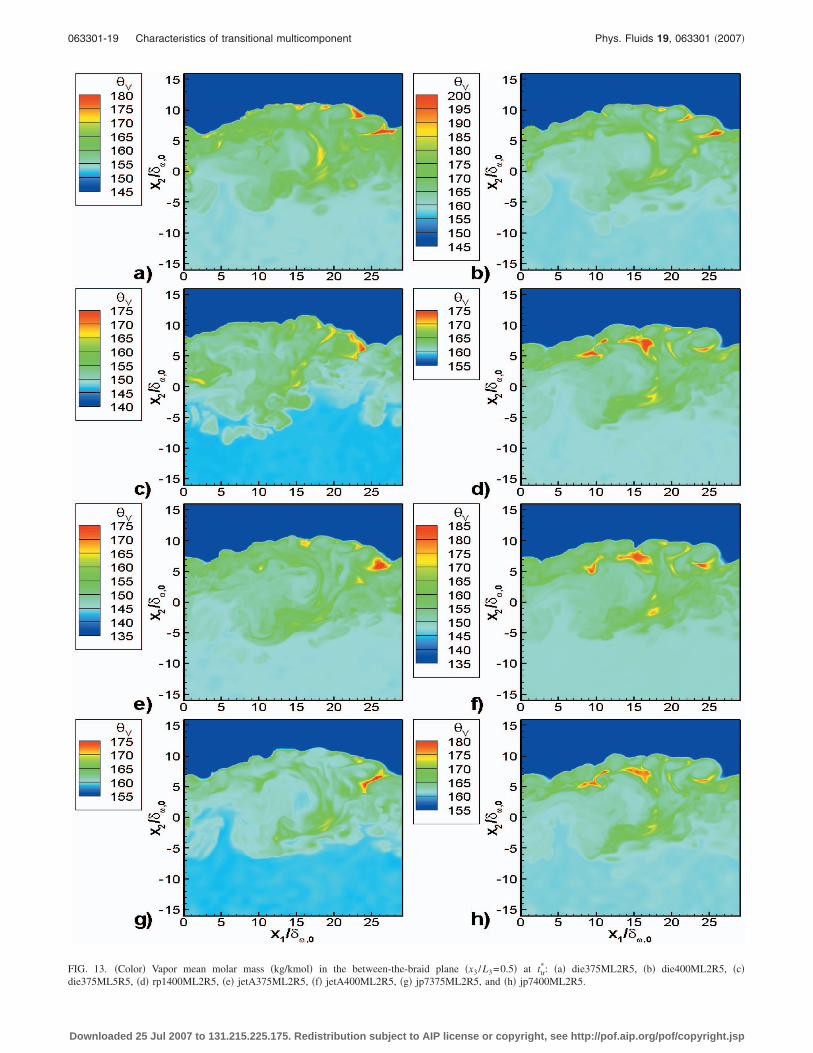
FIG. 13. �Color� Vapor mean molar mass �kg/kmol� in the between-the-braid plane �x3 /L3=0.5� at ttr*: �a� die375ML2R5, �b� die400ML2R5, �c�
die375ML5R5, �d� rp1400ML2R5, �e� jetA375ML2R5, �f� jetA400ML2R5, �g� jp7375ML2R5, and �h� jp7400ML2R5.
063301-19 Characteristics of transitional multicomponent Phys. Fluids 19, 063301 �2007�
Downloaded 25 Jul 2007 to 131.215.225.175. Redistribution subject to AIP license or copyright, see http://pof.aip.org/pof/copyright.jsp

FIG. 14. �Color� Standard deviation of the vapor composition �kg/kmol� in the x3 /L3=0.5 plane at ttr*: �a� die375ML2R5, �b� die400ML2R5, �c�
die375ML5R5, �d� rp1400ML2R5, �e� jetA375ML2R5, �f� jetA400ML2R5, �g� jp7375ML2R5, and �h� jp7400ML2R5.
063301-20 L. C. Selle and J. Bellan Phys. Fluids 19, 063301 �2007�
Downloaded 25 Jul 2007 to 131.215.225.175. Redistribution subject to AIP license or copyright, see http://pof.aip.org/pof/copyright.jsp
C. Liquid and vapor first-order statistics
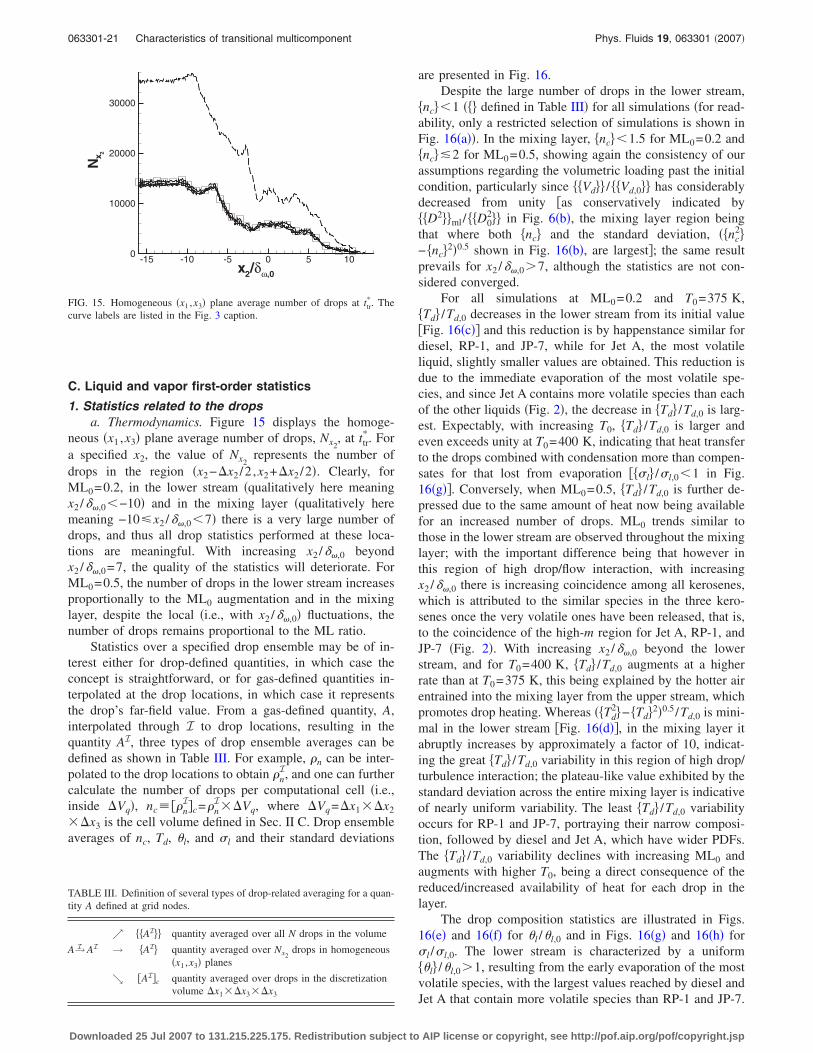
1. Statistics related to the dropsa. Thermodynamics. Figure 15 displays the homoge-
neous �x1 ,x3� plane average number of drops, Nx2, at ttr
*. Fora specified x2, the value of Nx2
represents the number ofdrops in the region �x2−�x2 /2 ,x2+�x2 /2�. Clearly, forML0=0.2, in the lower stream �qualitatively here meaningx2 /��,0�−10� and in the mixing layer �qualitatively heremeaning −10�x2 /��,0�7� there is a very large number ofdrops, and thus all drop statistics performed at these loca-tions are meaningful. With increasing x2 /��,0 beyondx2 /��,0=7, the quality of the statistics will deteriorate. ForML0=0.5, the number of drops in the lower stream increasesproportionally to the ML0 augmentation and in the mixinglayer, despite the local �i.e., with x2 /��,0� fluctuations, thenumber of drops remains proportional to the ML ratio.
Statistics over a specified drop ensemble may be of in-terest either for drop-defined quantities, in which case theconcept is straightforward, or for gas-defined quantities in-terpolated at the drop locations, in which case it representsthe drop’s far-field value. From a gas-defined quantity, A,interpolated through I to drop locations, resulting in thequantity AI, three types of drop ensemble averages can bedefined as shown in Table III. For example, �n can be inter-polated to the drop locations to obtain �n
I, and one can furthercalculate the number of drops per computational cell �i.e.,inside �Vq�, nc���n
I�c=�nI��Vq, where �Vq=�x1��x2
��x3 is the cell volume defined in Sec. II C. Drop ensembleaverages of nc, Td, �l, and �l and their standard deviations
are presented in Fig. 16.Despite the large number of drops in the lower stream,
nc��1 � � defined in Table III� for all simulations �for read-ability, only a restricted selection of simulations is shown inFig. 16�a��. In the mixing layer, nc��1.5 for ML0=0.2 and nc��2 for ML0=0.5, showing again the consistency of ourassumptions regarding the volumetric loading past the initialcondition, particularly since Vd�� / Vd,0�� has considerablydecreased from unity �as conservatively indicated by D2��ml/ D0
2�� in Fig. 6�b�, the mixing layer region beingthat where both nc� and the standard deviation, � nc
2�− nc�2�0.5 shown in Fig. 16�b�, are largest�; the same resultprevails for x2 /��,0�7, although the statistics are not con-sidered converged.
For all simulations at ML0=0.2 and T0=375 K, Td� /Td,0 decreases in the lower stream from its initial value�Fig. 16�c�� and this reduction is by happenstance similar fordiesel, RP-1, and JP-7, while for Jet A, the most volatileliquid, slightly smaller values are obtained. This reduction isdue to the immediate evaporation of the most volatile spe-cies, and since Jet A contains more volatile species than eachof the other liquids �Fig. 2�, the decrease in Td� /Td,0 is larg-est. Expectably, with increasing T0, Td� /Td,0 is larger andeven exceeds unity at T0=400 K, indicating that heat transferto the drops combined with condensation more than compen-sates for that lost from evaporation � �l� /�l,0�1 in Fig.16�g��. Conversely, when ML0=0.5, Td� /Td,0 is further de-pressed due to the same amount of heat now being availablefor an increased number of drops. ML0 trends similar tothose in the lower stream are observed throughout the mixinglayer; with the important difference being that however inthis region of high drop/flow interaction, with increasingx2 /��,0 there is increasing coincidence among all kerosenes,which is attributed to the similar species in the three kero-senes once the very volatile ones have been released, that is,to the coincidence of the high-m region for Jet A, RP-1, andJP-7 �Fig. 2�. With increasing x2 /��,0 beyond the lowerstream, and for T0=400 K, Td� /Td,0 augments at a higherrate than at T0=375 K, this being explained by the hotter airentrained into the mixing layer from the upper stream, whichpromotes drop heating. Whereas � Td
2�− Td�2�0.5 /Td,0 is mini-mal in the lower stream �Fig. 16�d��, in the mixing layer itabruptly increases by approximately a factor of 10, indicat-ing the great Td� /Td,0 variability in this region of high drop/turbulence interaction; the plateau-like value exhibited by thestandard deviation across the entire mixing layer is indicativeof nearly uniform variability. The least Td� /Td,0 variabilityoccurs for RP-1 and JP-7, portraying their narrow composi-tion, followed by diesel and Jet A, which have wider PDFs.The Td� /Td,0 variability declines with increasing ML0 andaugments with higher T0, being a direct consequence of thereduced/increased availability of heat for each drop in thelayer.
The drop composition statistics are illustrated in Figs.16�e� and 16�f� for �l /�l,0 and in Figs. 16�g� and 16�h� for�l /�l,0. The lower stream is characterized by a uniform �l� /�l,0�1, resulting from the early evaporation of the mostvolatile species, with the largest values reached by diesel andJet A that contain more volatile species than RP-1 and JP-7.
x2/δω,0
N
-15 -10 -5 0 5 100
10000
20000
30000x 2
FIG. 15. Homogeneous �x1 ,x3� plane average number of drops at ttr*. The
curve labels are listed in the Fig. 3 caption.
TABLE III. Definition of several types of drop-related averaging for a quan-tity A defined at grid nodes.
↗ AI�� quantity averaged over all N drops in the volume
A→I AI → AI� quantity averaged over Nx2drops in homogeneous
�x1 ,x3� planes
↘ �AI�c quantity averaged over drops in the discretizationvolume �x1��x3��x3
063301-21 Characteristics of transitional multicomponent Phys. Fluids 19, 063301 �2007�
Downloaded 25 Jul 2007 to 131.215.225.175. Redistribution subject to AIP license or copyright, see http://pof.aip.org/pof/copyright.jsp

However, while �l� /�l,0�1 for diesel and Jet A, indicativeof evaporation, �l� /�l,0�1 for RP-1 and JP-7 indicative ofcondensation, both with respect to the initial condition. In-creasing ML0 or T0 has opposite effects on �l� /�l,0 in that itdecreases/increases its value, portraying reduced/enhancedevaporation with respect to the baseline case, whereas it hasa qualitatively similar, increasing effect on �l� /�l,0 with theinfluence of ML0 being much weaker. It is clear that withinthe restricted parametric range investigated, ML0 has in thelower stream a much stronger influence on �l� /�l,0 than on �l� /�l,0, while the opposite is true for T0. Both � �l
2�
− �l�2�0.5 /�l,0 and � �l2�− �l�2�0.5 /�l,0 are minimal within the
lower stream, consistent with the low level of heterogeneityencountered in this region. At ML0=0.2 and T0=375 K, pro-ceeding into the mixing layer, �l� /�l,0 augments with x2 /��,0
at a larger rate for diesel and Jet A than for the other twokerosenes, which is evidence of increased evaporation of themost volatile species in diesel and Jet A that are not part ofthe RP-1 and JP-7 compositions. In contrast to the �l� /�l,0
variation, for �l� /�l,0 two distinct behaviors are apparent:RP-1 and JP-7, which have the narrower compositions, haveexperienced increasing condensation with increasing x2 /��,0
(a) x2/δω,0
{nc}
-15 -10 -5 0 5 10 15
0.5
1
1.5
2
(b) x2/δω,0
({n c2
}-{n
c}2)0.
5
-15 -10 -5 0 5 10 150
0.5
1
1.5
2
2.5
(c) x2/δω,0
{Td}/
Td,
0
-15 -10 -5 0 5 10 15
0.98
1
1.02
1.04
1.06
1.08
1.1
(d) x2/δω,0
({T
d2}-
{Td}
2 )0.5/T
d,0
-15 -10 -5 0 5 10 150
0.005
0.01
0.015
0.02
0.025
(e) x2/δω,0
{θl}/
θ l,0
-15 -10 -5 0 5 10 151
1.05
1.1
1.15
1.2
1.25
1.3
(f) x2/δω,0
({θ l2
}-{θ
l}2 )0.5/θ
l,0
-15 -10 -5 0 5 10 150
0.02
0.04
0.06
0.08
(g) x2/δω,0
{σl}/
σ l,0
-15 -10 -5 0 5 10 150.85
0.9
0.95
1
1.05
(h) x2/δω,0
({σ l2
}-{σ
l}2 )0.5/σ
l,0
-15 -10 -5 0 5 10 150
0.02
0.04
0.06
0.08
0.1
FIG. 16. Homogeneous �x1 ,x3� plane-average drop statistics at ttr
*. Fordie375ML2R5, die375ML5R5, andjetA375ML2R5: �a� and �b�. �a� nc�,�b� � nc
2�− � nc��2�0.5. Fordie375ML2R5, die375ML5R5,die400ML2R5, jetA375ML2R5,rp1375ML2R5, and jp7375ML2R5:�c�–�h�. �c� Td� /Td,0, �d� � Td
2� /Td,02
− � Td� /Td,0�2�0.5, �e� �l� /�l,0, �f�� �l
2� /�l,02 − � �l� /�l,0�2�0.5, �g� �l� /�l,0,
�h� � �l2� /�l,0
2 − � �l� /�l,0�2�0.5. Curvelabels listed in the Fig. 3 caption.
063301-22 L. C. Selle and J. Bellan Phys. Fluids 19, 063301 �2007�
Downloaded 25 Jul 2007 to 131.215.225.175. Redistribution subject to AIP license or copyright, see http://pof.aip.org/pof/copyright.jsp
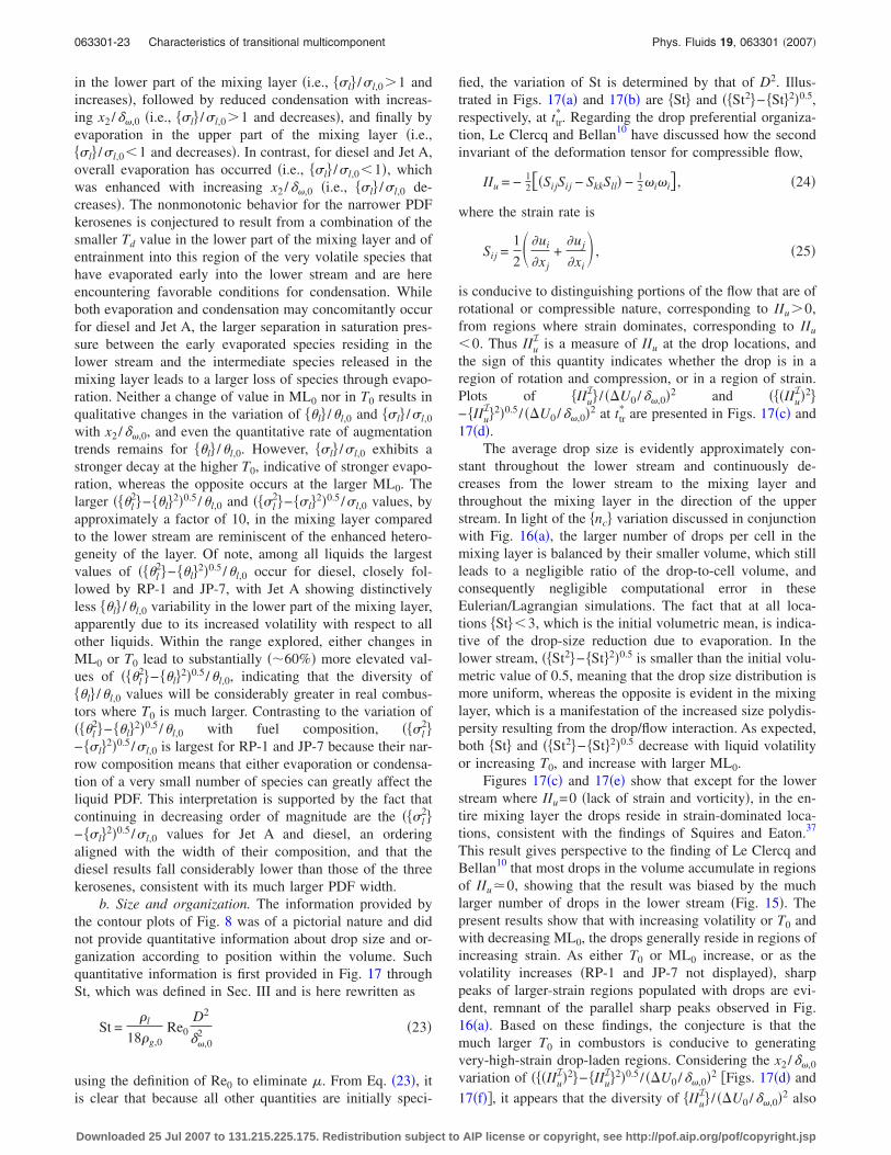
in the lower part of the mixing layer �i.e., �l� /�l,0�1 andincreases�, followed by reduced condensation with increas-ing x2 /��,0 �i.e., �l� /�l,0�1 and decreases�, and finally byevaporation in the upper part of the mixing layer �i.e., �l� /�l,0�1 and decreases�. In contrast, for diesel and Jet A,overall evaporation has occurred �i.e., �l� /�l,0�1�, whichwas enhanced with increasing x2 /��,0 �i.e., �l� /�l,0 de-creases�. The nonmonotonic behavior for the narrower PDFkerosenes is conjectured to result from a combination of thesmaller Td value in the lower part of the mixing layer and ofentrainment into this region of the very volatile species thathave evaporated early into the lower stream and are hereencountering favorable conditions for condensation. Whileboth evaporation and condensation may concomitantly occurfor diesel and Jet A, the larger separation in saturation pres-sure between the early evaporated species residing in thelower stream and the intermediate species released in themixing layer leads to a larger loss of species through evapo-ration. Neither a change of value in ML0 nor in T0 results inqualitative changes in the variation of �l� /�l,0 and �l� /�l,0
with x2 /��,0, and even the quantitative rate of augmentationtrends remains for �l� /�l,0. However, �l� /�l,0 exhibits astronger decay at the higher T0, indicative of stronger evapo-ration, whereas the opposite occurs at the larger ML0. Thelarger � �l
2�− �l�2�0.5 /�l,0 and � �l2�− �l�2�0.5 /�l,0 values, by
approximately a factor of 10, in the mixing layer comparedto the lower stream are reminiscent of the enhanced hetero-geneity of the layer. Of note, among all liquids the largestvalues of � �l
2�− �l�2�0.5 /�l,0 occur for diesel, closely fol-lowed by RP-1 and JP-7, with Jet A showing distinctivelyless �l� /�l,0 variability in the lower part of the mixing layer,apparently due to its increased volatility with respect to allother liquids. Within the range explored, either changes inML0 or T0 lead to substantially ��60%� more elevated val-ues of � �l
2�− �l�2�0.5 /�l,0, indicating that the diversity of �l� /�l,0 values will be considerably greater in real combus-tors where T0 is much larger. Contrasting to the variation of� �l
2�− �l�2�0.5 /�l,0 with fuel composition, � �l2�
− �l�2�0.5 /�l,0 is largest for RP-1 and JP-7 because their nar-row composition means that either evaporation or condensa-tion of a very small number of species can greatly affect theliquid PDF. This interpretation is supported by the fact thatcontinuing in decreasing order of magnitude are the � �l
2�− �l�2�0.5 /�l,0 values for Jet A and diesel, an orderingaligned with the width of their composition, and that thediesel results fall considerably lower than those of the threekerosenes, consistent with its much larger PDF width.
b. Size and organization. The information provided bythe contour plots of Fig. 8 was of a pictorial nature and didnot provide quantitative information about drop size and or-ganization according to position within the volume. Suchquantitative information is first provided in Fig. 17 throughSt, which was defined in Sec. III and is here rewritten as
St =�l
18�g,0Re0
D2
��,02 �23�
using the definition of Re0 to eliminate �. From Eq. �23�, itis clear that because all other quantities are initially speci-
fied, the variation of St is determined by that of D2. Illus-trated in Figs. 17�a� and 17�b� are St� and � St2�− St�2�0.5,respectively, at ttr
*. Regarding the drop preferential organiza-tion, Le Clercq and Bellan10 have discussed how the secondinvariant of the deformation tensor for compressible flow,
IIu = − 12��SijSij − SkkSll� − 1
2�i�i� , �24�
where the strain rate is
Sij =1
2� �ui
�xj+
�uj
�xi , �25�
is conducive to distinguishing portions of the flow that are ofrotational or compressible nature, corresponding to IIu�0,from regions where strain dominates, corresponding to IIu
�0. Thus IIuI is a measure of IIu at the drop locations, and
the sign of this quantity indicates whether the drop is in aregion of rotation and compression, or in a region of strain.Plots of IIu
I� / ��U0 /��,0�2 and � �IIuI�2�
− IIuI�2�0.5 / ��U0 /��,0�2 at ttr
* are presented in Figs. 17�c� and17�d�.
The average drop size is evidently approximately con-stant throughout the lower stream and continuously de-creases from the lower stream to the mixing layer andthroughout the mixing layer in the direction of the upperstream. In light of the nc� variation discussed in conjunctionwith Fig. 16�a�, the larger number of drops per cell in themixing layer is balanced by their smaller volume, which stillleads to a negligible ratio of the drop-to-cell volume, andconsequently negligible computational error in theseEulerian/Lagrangian simulations. The fact that at all loca-tions St��3, which is the initial volumetric mean, is indica-tive of the drop-size reduction due to evaporation. In thelower stream, � St2�− St�2�0.5 is smaller than the initial volu-metric value of 0.5, meaning that the drop size distribution ismore uniform, whereas the opposite is evident in the mixinglayer, which is a manifestation of the increased size polydis-persity resulting from the drop/flow interaction. As expected,both St� and � St2�− St�2�0.5 decrease with liquid volatilityor increasing T0, and increase with larger ML0.
Figures 17�c� and 17�e� show that except for the lowerstream where IIu=0 �lack of strain and vorticity�, in the en-tire mixing layer the drops reside in strain-dominated loca-tions, consistent with the findings of Squires and Eaton.37
This result gives perspective to the finding of Le Clercq andBellan10 that most drops in the volume accumulate in regionsof IIu�0, showing that the result was biased by the muchlarger number of drops in the lower stream �Fig. 15�. Thepresent results show that with increasing volatility or T0 andwith decreasing ML0, the drops generally reside in regions ofincreasing strain. As either T0 or ML0 increase, or as thevolatility increases �RP-1 and JP-7 not displayed�, sharppeaks of larger-strain regions populated with drops are evi-dent, remnant of the parallel sharp peaks observed in Fig.16�a�. Based on these findings, the conjecture is that themuch larger T0 in combustors is conducive to generatingvery-high-strain drop-laden regions. Considering the x2 /��,0
variation of � �IIuI�2�− IIu
I�2�0.5 / ��U0 /��,0�2 �Figs. 17�d� and
17�f��, it appears that the diversity of IIuI� / ��U0 /��,0�2 also
063301-23 Characteristics of transitional multicomponent Phys. Fluids 19, 063301 �2007�
Downloaded 25 Jul 2007 to 131.215.225.175. Redistribution subject to AIP license or copyright, see http://pof.aip.org/pof/copyright.jsp
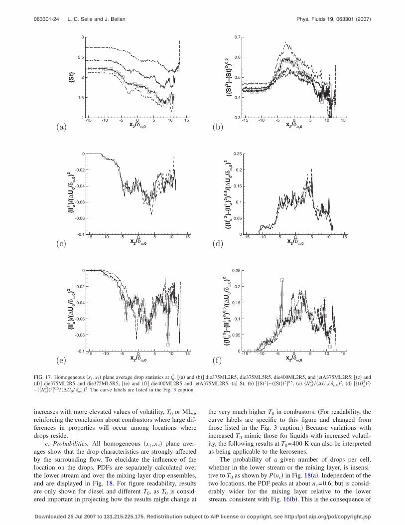
increases with more elevated values of volatility, T0 or ML0,reinforcing the conclusion about combustors where large dif-ferences in properties will occur among locations wheredrops reside.
c. Probabilities. All homogeneous �x1 ,x3� plane aver-ages show that the drop characteristics are strongly affectedby the surrounding flow. To elucidate the influence of thelocation on the drops, PDFs are separately calculated overthe lower stream and over the mixing-layer drop ensembles,and are displayed in Fig. 18. For figure readability, resultsare only shown for diesel and different T0, as T0 is consid-ered important in projecting how the results might change at
the very much higher T0 in combustors. �For readability, thecurve labels are specific to this figure and changed fromthose listed in the Fig. 3 caption.� Because variations withincreased T0 mimic those for liquids with increased volatil-ity, the following results at T0=400 K can also be interpretedas being applicable to the kerosenes.
The probability of a given number of drops per cell,whether in the lower stream or the mixing layer, is insensi-tive to T0 as shown by P�nc� in Fig. 18�a�. Independent of thetwo locations, the PDF peaks at about nc=0.6, but is consid-erably wider for the mixing layer relative to the lowerstream, consistent with Fig. 16�b�. This is the consequence of
(a) x2/δω,0
{St}
-15 -10 -5 0 5 10 151
1.5
2
2.5
3
(b) x2/δω,0
({S
t2}-
{St}
2 )0.5
-15 -10 -5 0 5 10 150.3
0.4
0.5
0.6
0.7
(c) x2/δω,0
{II uΙ
}/(∆
U0/
δ ω,0)2
-15 -10 -5 0 5 10 15-0.1
-0.08
-0.06
-0.04
-0.02
0
(d) x2/δω,0
({II uΙ
2}-
{II uΙ
}2)0
.5/(
∆U0/
δ ω,0)2
-15 -10 -5 0 5 10 150
0.05
0.1
0.15
0.2
0.25
(e) x2/δω,0
{II uΙ
}/(∆
U0/
δ ω,0)2
-15 -10 -5 0 5 10 15-0.1
-0.08
-0.06
-0.04
-0.02
0
(f) x2/δω,0
({II uΙ
2}-
{II uΙ
}2)0
.5/(
∆U0/
δ ω,0)2
-15 -10 -5 0 5 10 150
0.05
0.1
0.15
0.2
0.25
FIG. 17. Homogeneous �x1 ,x3� plane average drop statistics at ttr*. ��a� and �b�� die375ML2R5, die375ML5R5, die400ML2R5, and jetA375ML2R5; ��c� and
�d�� die375ML2R5 and die375ML5R5; ��e� and �f�� die400ML2R5 and jetA375ML2R5. �a� St, �b� � St2�− � St��2�0.5, �c� IIuI� / ��U0 /��,0�2, �d� � �IIu
I�2�− � IIu
I��2�0.5 / ��U0 /��,0�2. The curve labels are listed in the Fig. 3 caption.
063301-24 L. C. Selle and J. Bellan Phys. Fluids 19, 063301 �2007�
Downloaded 25 Jul 2007 to 131.215.225.175. Redistribution subject to AIP license or copyright, see http://pof.aip.org/pof/copyright.jsp

drop segregation in the mixing layer, as seen in Figs. 17�c�and 17�e�. In contrast, P�Td� in Fig. 18�b� exhibits highspecificity both to T0 and to the drop location. Independentof T0, Td has a much larger range of higher values in themixing layer than in the lower stream. Also independent ofT0, in both regions, the PDF displays a major peak and thena minor peak at smaller Td values; although the larger peak isat the same Td value in both regions, in the mixing layer theminor peak is at inferior values than in the lower stream,making the lower-stream PDF wider in the region of mostprobability. The dual Td peak corresponds to regions of rela-tively low T in the central streamwise portion of the domaincaused by the lower p at the center of the final vortex �notshown�, surrounded by regions of higher p and thus larger T.Figure 9�a� clearly depicts the dual Td preferential values inthe lower portion of the mixing layer. The major peak indi-cates a preferential value, which for T0=375 K is in thelower stream slightly inferior to T0. The location of this mi-nor peak, which indicates the lower boundary of the range ofmost probable values, shows that even within these mostprobable values, the mixing layer has more variability thanthe lower stream, consistent with the physical understandingderived from scrutiny of Fig. 16�d�.
The composition information presented in Figs. 18�c�and 18�d� shows that independent of T0, P��l� peaks at thesame �l but is much narrower in the lower stream than in themixing layer, consistent with the similar history of all drops
in the lower stream and the diversity of drop history for themixing layer drops, as clearly seen in Fig. 9�b�. At larger T0,P��l� is translated to the range of larger �l as the more vola-tile species have been released earlier from the drops, and itswidth increases, consistent with the information of Fig. 16�f�.Of note, some drops have a liquid mean molar mass as heavyas 260 kg/kmol, and this value increases to �300 kg/kmolat T0=400 K �not shown�. Thus, for the much larger T0 incombustors, it is expected that the mean molar mass of theliquid will increase from the present values, leading to cokeor cenosphere formation when species as heavy as�500 kg/kmol have a non-negligible presence in thedrop.38–40 Complementary to P��l�, P��l� shows that the pre-ferred value is similar for both lower-stream and mixing-layer regions, and that the location of the peak slightly in-creases with larger T0. Independent of T0, the P��l� width islarger in the mixing layer, consistent with the information inFig. 16�h�.
2. Vapor statistics
Homogeneous-plane averages of �v /�v,0 and �v /�v,0 atttr* are displayed in Fig. 19. For both ��v� /�v,0 and ��v� /�v,0,
the lower stream is characterized by a uniform distribution,with the values increasing into and culminating in the mixinglayer, then decreasing and reaching unity in the upper stream.
(a) nc
P(n
c)
0 2 4 60
0.2
0.4
0.6
0.8
(b) Td
P(T
d)
340 350 360 370 380 3900
0.05
0.1
0.15
0.2
(c) θl
P(θ
l)
200 220 240 2600
0.05
0.1
0.15
0.2
(d) σl
P(σ
l)35 40 45 50
0
0.1
0.2
0.3
FIG. 18. Probabilities computed over the drop ensemble in the lower stream ��� and in the mixing layer ��� for die375ML2R5 and die400ML2R5 at ttr*. The
criterion for defining the lower stream and the mixing layer is that of Sec. IV A 2. The curve labels are changed from those listed in the Fig. 3 caption:die375ML2R5 ——– and die400ML2R5 − − −. �a� P�nc�, �b� P�Td�, �c� P��l� and �d� P��l�.
063301-25 Characteristics of transitional multicomponent Phys. Fluids 19, 063301 �2007�
Downloaded 25 Jul 2007 to 131.215.225.175. Redistribution subject to AIP license or copyright, see http://pof.aip.org/pof/copyright.jsp
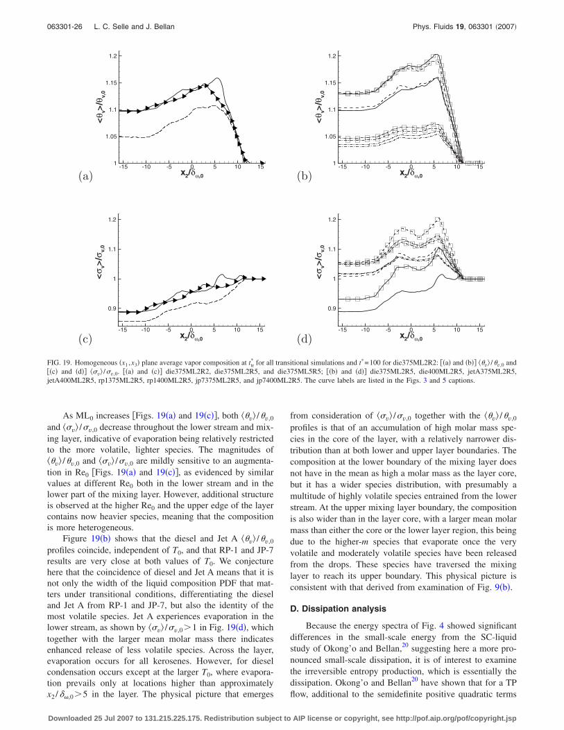
As ML0 increases �Figs. 19�a� and 19�c��, both ��v� /�v,0
and ��v� /�v,0 decrease throughout the lower stream and mix-ing layer, indicative of evaporation being relatively restrictedto the more volatile, lighter species. The magnitudes of��v� /�v,0 and ��v� /�v,0 are mildly sensitive to an augmenta-tion in Re0 �Figs. 19�a� and 19�c��, as evidenced by similarvalues at different Re0 both in the lower stream and in thelower part of the mixing layer. However, additional structureis observed at the higher Re0 and the upper edge of the layercontains now heavier species, meaning that the compositionis more heterogeneous.
Figure 19�b� shows that the diesel and Jet A ��v� /�v,0
profiles coincide, independent of T0, and that RP-1 and JP-7results are very close at both values of T0. We conjecturehere that the coincidence of diesel and Jet A means that it isnot only the width of the liquid composition PDF that mat-ters under transitional conditions, differentiating the dieseland Jet A from RP-1 and JP-7, but also the identity of themost volatile species. Jet A experiences evaporation in thelower stream, as shown by ��v� /�v,0�1 in Fig. 19�d�, whichtogether with the larger mean molar mass there indicatesenhanced release of less volatile species. Across the layer,evaporation occurs for all kerosenes. However, for dieselcondensation occurs except at the larger T0, where evapora-tion prevails only at locations higher than approximatelyx2 /��,0�5 in the layer. The physical picture that emerges
from consideration of ��v� /�v,0 together with the ��v� /�v,0
profiles is that of an accumulation of high molar mass spe-cies in the core of the layer, with a relatively narrower dis-tribution than at both lower and upper layer boundaries. Thecomposition at the lower boundary of the mixing layer doesnot have in the mean as high a molar mass as the layer core,but it has a wider species distribution, with presumably amultitude of highly volatile species entrained from the lowerstream. At the upper mixing layer boundary, the compositionis also wider than in the layer core, with a larger mean molarmass than either the core or the lower layer region, this beingdue to the higher-m species that evaporate once the veryvolatile and moderately volatile species have been releasedfrom the drops. These species have traversed the mixinglayer to reach its upper boundary. This physical picture isconsistent with that derived from examination of Fig. 9�b�.
D. Dissipation analysis
Because the energy spectra of Fig. 4 showed significantdifferences in the small-scale energy from the SC-liquidstudy of Okong’o and Bellan,20 suggesting here a more pro-nounced small-scale dissipation, it is of interest to examinethe irreversible entropy production, which is essentially thedissipation. Okong’o and Bellan20 have shown that for a TPflow, additional to the semidefinite positive quadratic terms
(a) x2/δω,0
<θ v>
/θv,
0
-15 -10 -5 0 5 10 151
1.05
1.1
1.15
1.2
(b) x2/δω,0
<θ v>
/θv,
0
-15 -10 -5 0 5 10 151
1.05
1.1
1.15
1.2
(c) x2/δω,0
<σ v>
/σv,
0
-15 -10 -5 0 5 10 15
0.9
1
1.1
1.2
(d) x2/δω,0
<σ v>
/σv,
0
-15 -10 -5 0 5 10 15
0.9
1
1.1
1.2
FIG. 19. Homogeneous �x1 ,x3� plane average vapor composition at ttr* for all transitional simulations and t*=100 for die375ML2R2: ��a� and �b�� ��v� /�v,0 and
��c� and �d�� ��v� /�v,0. ��a� and �c�� die375ML2R2, die375ML2R5, and die375ML5R5; ��b� and �d�� die375ML2R5, die400ML2R5, jetA375ML2R5,jetA400ML2R5, rp1375ML2R5, rp1400ML2R5, jp7375ML2R5, and jp7400ML2R5. The curve labels are listed in the Figs. 3 and 5 captions.
063301-26 L. C. Selle and J. Bellan Phys. Fluids 19, 063301 �2007�
Downloaded 25 Jul 2007 to 131.215.225.175. Redistribution subject to AIP license or copyright, see http://pof.aip.org/pof/copyright.jsp
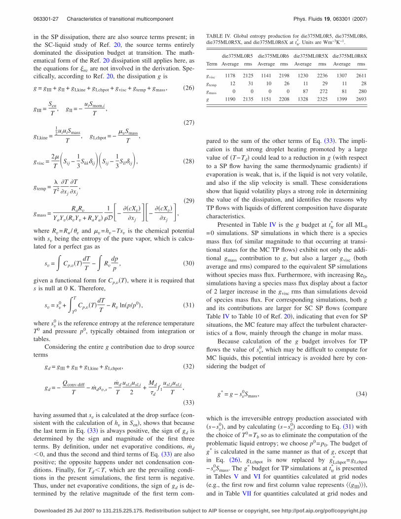
in the SP dissipation, there are also source terms present; inthe SC-liquid study of Ref. 20, the source terms entirelydominated the dissipation budget at transition. The math-ematical form of the Ref. 20 dissipation still applies here, asthe equations for nv are not involved in the derivation. Spe-cifically, according to Ref. 20, the dissipation g is
g = gIII + gII + gI,kine + gI,chpot + gvisc + gtemp + gmass, �26�
gIII =Sen
T, gII = −
uiSmom,i
T,
�27�
gI,kine =12uiuiSmass
T, gI,chpot = −
�vSmass
T,
gvisc =2�
T�Sij −
1
3Skk�ij�Sij −
1
3Sll�ij , �28�
gtemp =�
T2
�T
�xj
�T
�xj,
�29�
gmass =RaRv
YaYv�RvYv + RaYa�1
�D�−��cXv�
�xj�−
��cXv��xj
,
where Rv=Ru /�v and �v=hv−Tsv is the chemical potentialwith sv being the entropy of the pure vapor, which is calcu-lated for a perfect gas as
sv =� Cp,v�T�dT
T−� Rv
dp
p, �30�
given a functional form for Cp,v�T�, where it is required thats is null at 0 K. Therefore,
sv = sv0 + �
T0
T
Cp,v�T�dT
T− Rv ln�p/p0� , �31�
where sv0 is the reference entropy at the reference temperature
T0 and pressure p0, typically obtained from integration ortables.
Considering the entire g contribution due to drop sourceterms
gd = gIII + gII + gI,kine + gI,chpot, �32�
gd = −Qconv-diff
T− mdsv,s −
md
T
usl,iusl,i
2+
Md
�df1
usl,iusl,i
T,
�33�
having assumed that sv is calculated at the drop surface �con-sistent with the calculation of hv in Sen�, shows that becausethe last term in Eq. �33� is always positive, the sign of gd isdetermined by the sign and magnitude of the first threeterms. By definition, under net evaporative conditions, md
�0, and thus the second and third terms of Eq. �33� are alsopositive; the opposite happens under net condensation con-ditions. Finally, for Td�T, which are the prevailing condi-tions in the present simulations, the first term is negative.Thus, under net evaporative conditions, the sign of gd is de-termined by the relative magnitude of the first term com-
pared to the sum of the other terms of Eq. �33�. The impli-cation is that strong droplet heating promoted by a largevalue of �T−Td� could lead to a reduction in g �with respectto a SP flow having the same thermodynamic gradients� ifevaporation is weak, that is, if the liquid is not very volatile,and also if the slip velocity is small. These considerationsshow that liquid volatility plays a strong role in determiningthe value of the dissipation, and identifies the reasons whyTP flows with liquids of different composition have disparatecharacteristics.
Presented in Table IV is the g budget at ttr* for all ML0
=0 simulations. SP simulations in which there is a speciesmass flux �of similar magnitude to that occurring at transi-tional states for the MC TP flows� exhibit not only the addi-tional gmass contribution to g, but also a larger gvisc �bothaverage and rms� compared to the equivalent SP simulationswithout species mass flux. Furthermore, with increasing Re0,simulations having a species mass flux display about a factorof 2 larger increase in the gvisc rms than simulations devoidof species mass flux. For corresponding simulations, both gand its contributions are larger for SC SP flows �compareTable IV to Table 10 of Ref. 20�, indicating that even for SPsituations, the MC feature may affect the turbulent character-istics of a flow, mainly through the change in molar mass.
Because calculation of the g budget involves for TPflows the value of sv
0, which may be difficult to compute forMC liquids, this potential intricacy is avoided here by con-sidering the budget of
g* = g − sv0Smass, �34�
which is the irreversible entropy production associated with�s−sv
0�, and by calculating �s−sv0� according to Eq. �31� with
the choice of T0=Tb so as to eliminate the computation of theproblematic liquid entropy; we choose p0= p0. The budget ofg* is calculated in the same manner as that of g, except thatin Eq. �26�, gI,chpot is now replaced by gI,chpot
* =gI,chpot
−sv0Smass. The g* budget for TP simulations at ttr
* is presentedin Tables V and VI for quantities calculated at grid nodes�e.g., the first row and first column value represents ��gIII���,and in Table VII for quantities calculated at grid nodes and
TABLE IV. Global entropy production for die375ML0R5, die375ML0R6,die375ML0R5X, and die375ML0R6X at ttr
*. Units are Wm−3K−1.
die375ML0R5 die375ML0R6 die375ML0R5X die375ML0R6X
Term Average rms Average rms Average rms Average rms
gvisc 1178 2125 1141 2198 1230 2236 1307 2611
gtemp 12 31 10 26 11 29 11 28
gmass 0 0 0 0 87 272 81 280
g 1190 2135 1151 2208 1328 2325 1399 2693
063301-27 Characteristics of transitional multicomponent Phys. Fluids 19, 063301 �2007�
Downloaded 25 Jul 2007 to 131.215.225.175. Redistribution subject to AIP license or copyright, see http://pof.aip.org/pof/copyright.jsp

then interpolated at the drop location �e.g., the first row andfirst column value represents gIII
I ��, i.e., gIII→I gIIII → gIII
I ���.All tables list averages, rms, and the % of the ensemblewhere positive or negative values occur. The vertical listingof terms in the tables follows that of Ref. 20 �where theywere listed in decreasing order of rms values for the baselinecase� for easy comparison of terms other than gI,chpot
* and g*.It is apparent from Table V that, excluding the noncom-
parable gI,chpot* , the decreasing order of the rms values re-
mains from the SC n-decane study of Ref. 20. However, atthe same initial conditions, gIII is smaller in magnitude,whether average or rms, and this holds for diesel and allkerosenes �Tables V and VI�, with RP-1, the liquid with thenarrowest PDF, approaching n-decane most closely. For die-sel at the �7% relatively� higher T0 �Table V�, gIII is larger by�15% for the average and �23% for the rms confirming theimportant influence of T0 for liquids of low volatility. A simi-lar comparison for Jet A �Table VI� reveals practically novariation with T0, which is attributed to the more modest roleof a such small relative increase in T0 for fuels of highervolatility. Because
sign�gIII� = − sign�v jFj + Qconv-diff + Qevap
+ md�v jv j
2+ ClTd
= − sign�v jFj +�Nu
D
ln�1 + BT�BT
�D2�T − Td�
+ md�Lveff
B+
v jv j
2+ ClTd �35�
it is clear that gIII�0 only if the sum of the first two terms,representing the work due to drag and drop heating, domi-nates the effect of evaporation. Although ��gIII���0 for allsimulations, and in most of the domain gIII�0, there is anon-negligible % �more than 15%� of the volumetric domainwhere its value is negative for all ML0=0.2 simulations, andthis percentage increases at the larger T0. With increasingML0, the % of the domain with gIII�0 decreases, which isattributed to the reduction in md combined with the largerdrag and flow-to-drop heat transfer associated with the muchlarger number of drops. Of note, the percentages of strictly
TABLE VI. Volumetric entropy production for jetA375ML2R5, jetA400ML2R5, and rp1375ML2R5 at ttr*.
Units are Wm−3K−1.
jetA375ML2R5 jetA400ML2R5 rp1375ML2R5
Volumetric Volumetric Volumetric
Term Average rms %�0 %�0 Average rms %�0 %�0 Average rms %�0 %�0
gIII 10018 35523 58 18 10016 37759 56 19 12383 39873 61 15
gI,chpot* −15351 63611 25 51 −14524 64159 26 50 −19090 68136 19 57
gvisc 3288 7310 100 0 3228 7235 100 0 3373 7480 100 0
gII −6 3527 34 41 −95 2744 27 48 −28 3574 31 45
gmass 201 770 100 0 254 942 100 0 197 745 100 0
gtemp 182 577 100 0 294 943 100 0 153 469 100 0
gI,kine 43 297 51 25 38 321 50 26 63 333 57 19
g* −1625 27387 77 23 −1625 27387 77 23 −2949 27565 72 28
TABLE V. Volumetric entropy production for die375ML2R5, die375ML5R5, and die400ML2R5 at ttr*. Units
are Wm−3K−1.
die375ML2R5 die375ML5R5 die400ML2R5
Volumetric Volumetric Volumetric
Term Average rms %�0 %�0 Average rms %�0 %�0 Average rms %�0 %�0
gIII 7307 24695 57 17 16097 42372 70 9 8423 30536 55 22
gI,chpot* −11479 50145 28 47 −23045 89873 28 51 −12203 58544 29 46
gvisc 3296 7248 100 0 3479 7543 100 0 3314 7296 100 0
gII 152 4612 37 38 575 9647 42 37 26 3767 35 39
gmass 122 447 100 0 155 632 100 0 160 601 100 0
gtemp 138 426 100 0 176 599 100 0 240 731 100 0
gI,kine 30 232 47 28 71 365 51 28 27 281 46 29
g* −435 24917 78 22 −2492 45894 72 28 −14 27593 80 20
063301-28 L. C. Selle and J. Bellan Phys. Fluids 19, 063301 �2007�
Downloaded 25 Jul 2007 to 131.215.225.175. Redistribution subject to AIP license or copyright, see http://pof.aip.org/pof/copyright.jsp

positive and strictly negative gIII activity do not necessarilyadd up to 100 because there may be no activity at all in theconsiderable part of the domain represented by the upperstream; in fact, only �74% to 79% of the volume is prone tonon-null gIII activity, and this percentage increases at largerML0 or T0 but is not sensitive to liquid volatility.
For all fuels and under all conditions, ��gI,chpot* �� �0 and
dominates g* in magnitude; similarly, the rms of gI,chpot* is the
largest among all contributions to g*. This means that thecomposition of the fuel has a major impact on the �s−sv
0�production. Both the gI,chpot
* average and rms increase withML0, but slightly less than proportionally, and with T0 orlarger fuel volatility.
In contrast to gIII, the gvisc contribution, whether averageor rms, is larger in magnitude here �by �20%� than in Ref.20, decisively explaining why the smallest scales in the en-ergy spectra of Fig. 4 contain orders of magnitude less en-ergy here than in the equivalent spectra of Ref. 20. None ofthe parameters considered here �ML0,T0 or liquid volatility�affect this conclusion, which seems to be entirely related tothe MC aspect of the flow. Like for all other flux-relateddissipation terms �i.e., gmass and gtemp�, the entire domain hasa positive activity. Relative to the SP budget of Table IV,gvisc is now larger by �35% in average and �29% in rms.Although at first consideration this result may seem contra-dictory to the reduced energy in the small scales for SP flowsevident in Figs. 4�c� and 4�d�, the fact is that the initial en-ergy in SP and TP flows is not the same �because of theadditional energy due to the presence of drops� as shown inFig. 4�b�, and moreover the kinetic energy in TP flows firstincreases with time compared to the decrease experienced bySP flows �Fig. 5�a��, which brings the correct perspective tothis result.
Previously analyzed in detail by Okong’o and Bellan20
in their n-decane study, here ��gII���0 for diesel, but��gII���0 for all kerosenes independent of T0, indicating thatfor diesel it is drag that dominates, whereas for the kerosenesit is evaporation that governs the sign of this term. Confirm-ing this interpretation, ��gII�� becomes increasingly positiveat the larger ML0 and substantially decreases with augment-ing T0; the same variation is apparent for the rms, portrayingthe increased �decreased� heterogeneity in the flow with in-
creasing �decreasing� ML0 �T0�. For diesel, an approximatelysimilar % of the domain experiences positive or negative gII
activity, whereas for all kerosenes there is a larger % ofnegative activity regions. At the larger ML0, the % of regionsof positive activity increases, which results from the in-creased drag on a larger number of drops combined with thedecreased evaporation due to heat-transfer limitations; at thelarger T0 the opposite holds, owing to the increased evapo-ration rate due to promoted heat transfer combined with thedecreased drag on smaller drops.
Both gmass and gtemp are for all liquids more than a factorof 50 smaller than the largest g contribution, and gI,kine iseven smaller. Because
sign�gI,kine� = sign�−d�N�l�
dt �36�
this means that regions of gI,kine�0 �gI,kine�0� correspondto net evaporation �net condensation�. Apparently, indepen-dent of the liquid, ML0 or T0, net evaporation occurs in alarger % of the domain than net condensation. The keroseneswith a narrower composition PDF �i.e., RP-1 and JP-7� areparticularly prone to net evaporation over a larger part of thedomain due to the lack of much more volatile species thanthe mean that could have condensed on the drops. Similarly,the extent of net evaporation regions also becomes more pre-ponderant with increasing ML0, presumably due to the largernumber of drops, which increases the portions of the domainpopulated by drops. The results show almost no sensitivity toT0, however with increasing liquid volatility, gI,kine increases,consistent with the plots of Fig. 5�b�.
Compared to MC SP simulations, the values of all fluxcontributions of g are larger for MC TP flows, whether av-erage or rms; this is similar to the SC results of Ref. 20.However, one noteworthy distinguishing feature is that ingoing from SC to MC flows, ��gvisc�� increases by only halfas much from SP to TP situations, whereas the gvisc rmsaugmentation is a factor of 3 larger than for SC flows, sug-gesting that the MC-liquid phase change suppresses the in-crease in the average and introduces additional variability ingvisc.
Whereas Tables V and VI correspond to the dissipation
TABLE VII. Drop-ensemble-based entropy production for die375ML2R5, die375ML5R5, and jetA375ML2R5at ttr
*. Units are Wm−3K−1.
die375ML2R5 die375ML5R5 jetA375ML2R5
Drop-ensemble Drop-ensemble Drop-ensemble
Term Average rms %�0 %�0 Average rms %�0 %�0 Average rms %�0 %�0
gIII 27210 63584 64 36 42611 97944 82 18 38499 100234 63 37
gI,chpot* −45172 134423 59 41 −59245 209757 60 40 −61279 184177 52 48
gvisc 2308 5808 100 0 2560 6961 100 0 2199 5589 100 0
gII 190 12785 48 52 455 25300 52 48 −155 9413 48 52
gmass 152 543 99 1 152 748 99 1 268 1045 99 1
gtemp 288 848 99 1 280 1156 99 1 385 1190 99 1
gI,kine 99 542 41 59 134 635 40 60 143 731 48 52
g* −14926 66548 66 34 −13053 106403 71 29 −19939 79451 64 36
063301-29 Characteristics of transitional multicomponent Phys. Fluids 19, 063301 �2007�
Downloaded 25 Jul 2007 to 131.215.225.175. Redistribution subject to AIP license or copyright, see http://pof.aip.org/pof/copyright.jsp

in an Eulerian framework, Table VII is an example of the gasdissipation g* at ttr
* as “seen” by the drops, that is, in a La-grangian framework. In this Lagrangian framework, the %regions of positive activity added to the % of negative activ-ity locations yields 100%. A small error is evident in thecomputed values for gmass and gtemp, which, although addingto the expected 100%, show an unphysical 1% region ofnegative activity; the computation error is evidently due tothe operation I. Whereas ���g*��� increases with increasingML0 and decreases with increasing T0 �Table V�, � �g*�I���decreases with increasing ML0 �Table VII� and varies errati-cally with the composition �not shown; it increases for dieseland JP-7 and decreases for Jet A and RP-1�. The variation of���g*��� with increasing fuel volatility, that is, with a smaller� �see Table I�, is nonmonotonic as a decrease is shown fromJet A to diesel �Tables V and VI�, but an increase occurs fromJet A to RP-1 �Table VI�; however, � �g*�I��� increasesmonotonically with � �not shown�. Similar to ��g*��, thenegative value of �g*�I�� represents the dominance ofgI,chpot
* , which is the only negative contribution. For all liq-uids �only diesel and Jet A shown� and for each specifiedsimulation, over the drop ensemble gIII has a much largervalue than over the volume, both average and rms; gI,chpot
* isin average larger in magnitude than volumetrically by a fac-tor of �2.5 to 4.5 for diesel and �4 for kerosenes, and itsrms is larger than volumetrically by a factor of �2 to 3; gvisc
is smaller both in average and rms for all liquids; gII has asimilar average value but a larger rms for diesel, and a muchlarger absolute value �by a factor of 26� and a much largerrms for Jet A �and both other kerosenes; not shown�; for allliquids, gmass and gtemp are 50% to a factor of 2 larger inaverage and rms when calculated over the drop ensemble;and independently of liquid, gI,kine
I �� is larger by a factor of2–3 than ��gI,kine�� with a larger % of gI,kine
I allocated to nega-tive values, corresponding to net condensation, and approxi-mately a factor of 2 larger in rms. For all liquids, the T0
variation of each contribution to �g*�I is consistent with thatseen for the domain statistics. The general picture obtainedwhen scrutinizing g* over the drop ensemble is that althoughthe general conclusions are similar to those obtained for theg* statistics over the volumetric domain, the details may varyconsiderably. This raises the question of how the composi-tion PDF, which according to �16� is a DGPDF for the vaporat the drop surface, evolves in mathematical form from thedrop surface to the grid nodes. This question is addressednext.
E. Vapor-composition PDF representation
The dissipation discussion above raises the possibilitythat given the different “appearance” of the flow in the Eu-lerian or Lagrangian frameworks, the vapor-compositionPDF, which is a DGPDF at drop locations, may not have thesame mathematical form at grid nodes. Le Clercq andBellan15 interpreted their pretransitional simulations to meanthat the vapor composition remained a DGPDF, an approxi-mation that was justified by the relatively lower heterogene-ity in composition relative to the present transitional results.Thus, here we explore the mathematical form of the vapor-
composition PDF through the excess moments nv� of Eq. �4�.That is, we compare the vapor-composition PDF, of whichwe only know the calculated first four moments computed asthe solution of the gas-phase equations, with the SGPDF thathas the same first two moments as the computed PDF; thiscomposition PDF has so far an unknown mathematical form.
Figures 20�a� and 20�b� show �3v� /3vSGPDF� and Figs.
20�c� and 20�d� display �4v� /4vSGPDF�. In all cases, both
�3v� /3vSGPDF� and �4v� /4v
SGPDF� are very small, �O�10−3�, andnegative, although the fourth-order moment tends to havevalues larger by a factor of 5 than the corresponding thirdmoments. The smallest magnitude of �3v� /3v
SGPDF� and�4v� /4v
SGPDF� is in the lower and upper streams, while themixing layer hosts the largest values. The deviation from theSGPDF increases with decreasing ML0 �Figs. 20�a� and20�c�� and with increasing T0 �Figs. 20�b� and 20�d��; atmore elevated Re0, the region of larger departure shifts to-ward the upper stream, and the departure from the SGPDF islarger �Figs. 20�a� and 20�c��. A smaller ML0, larger T0 orhigher Re0 promotes evaporation �as evidenced by D2��ml/ D0
2�� in Fig. 6�b�� and thus the release of speciesthat potentially could condense and could contribute to theformation of a PDF different from the SGPDF. Notably,Harstad et al.14 showed that for the liquid, departures fromthe SGPDF increased at larger evaporation rates and thesedepartures were traced to species condensation on the drops.The departure from the SGPDF decreases in the lowerstream with increasing value of the lowest-m species �Fig. 2�,as vapor evolution in this region is entirely due to the mostvolatile species of the liquid. Because Jet A exhibits consid-erably more evaporation here than diesel and the two otherkerosenes, its Pv displays the largest departure from the SG-PDF �Figs. 20�b� and 20�d��. The mixing layer being a regionof evaporation where a multitude of molar mass species arereleased from the drops, the departures from the SGPDFalign here with the width of Pl,0 because more species areavailable for condensation, and accordingly the vapor ema-nating from the liquid with the largest Pl,0 width—diesel—has the largest departure from the SGPDF.
Finally, �l� �see Eq. �1� for the definition of �l� is illus-trated in Fig. 20�e� at ttr
*, and now assuming that the vapor-composition PDF is of the double-Gamma form, ��v� is por-trayed in Fig. 20�f� also at ttr
*. The jagged aspect of the curvesin Fig. 20�e� is due to ensemble averaging a liquid variableover drops residing in planes. The activity is almost uniquelyconfined to the mixing layer. Clearly, the deviation of thevapor composition from SGPDF is greater by �50% in thevapor than in the liquid, although in both cases the departureis small; according to Harstad et al.,14 however, this smalldeparture is crucial to the physical tenability of the model.Thus, if Pv is a DGPDF, its departure from the equivalentSGPDF is larger than that of Pl from its corresponding SG-PDF. Comparing all liquids according to their composition, arelatively larger departure from the SGPDF in the liquidleads to a relatively smaller departure for the vapor. We in-terpret this opposite variation as being the effect of conden-sation onto the drops, which depresses the minor double-Gamma peak in the vapor and increases it in the liquid. This
063301-30 L. C. Selle and J. Bellan Phys. Fluids 19, 063301 �2007�
Downloaded 25 Jul 2007 to 131.215.225.175. Redistribution subject to AIP license or copyright, see http://pof.aip.org/pof/copyright.jsp
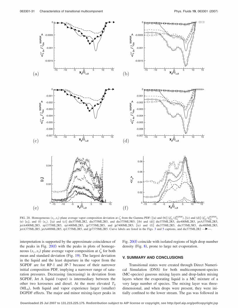
interpretation is supported by the approximate coincidence ofthe peaks in Fig. 20�f� with the peaks in plots of homoge-neous �x1 ,x3� plane average vapor composition at ttr
* for bothmean and standard deviation �Fig. 19�. The largest deviationin the liquid and the least departure in the vapor from theSGPDF are for RP-1 and JP-7 because of their narrowerinitial composition PDF, implying a narrower range of satu-ration pressures. Decreasing �increasing� in deviation fromSGPDF, Jet A liquid �vapor� is intermediary between theother two kerosenes and diesel. At the more elevated T0
�ML0�, both liquid and vapor experience larger �smaller�DGPDF effects. The major and minor mixing-layer peaks in
Fig. 20�f� coincide with isolated regions of high drop numberdensity �Fig. 8�, prone to large net evaporation.
V. SUMMARY AND CONCLUSIONS
Transitional states were created through Direct Numeri-cal Simulation �DNS� for both multicomponent-species�MC-species� gaseous mixing layers and drop-laden mixinglayers where the evaporating liquid is a MC mixture of avery large number of species. The mixing layer was three-dimensional, and when drops were present, they were ini-tially confined to the lower stream. The gas was followed in
(a) x2/δω,0
<ξ’
3v/ξ
3vS
GP
DF>
-15 -10 -5 0 5 10 15
-0.0015
-0.001
-0.0005
0
(b) x2/δω,0
<ξ’
3v/ξ
3vS
GP
DF>
-15 -10 -5 0 5 10 15
-0.0015
-0.001
-0.0005
0
(c) x2/δω,0
<ξ’
4v/ξ
4vS
GP
DF>
-15 -10 -5 0 5 10 15-0.007
-0.006
-0.005
-0.004
-0.003
-0.002
-0.001
0
(d) x2/δω,0
<ξ’
4v/ξ
4vS
GP
DF>
-15 -10 -5 0 5 10 15-0.007
-0.006
-0.005
-0.004
-0.003
-0.002
-0.001
0
(e) x2/δω,0
{εl}
-15 -10 -5 0 5 10 150
0.02
0.04
(f) x2/δω,0
<ε v>
-15 -10 -5 0 5 10 150
0.02
0.04
0.06
0.08
FIG. 20. Homogeneous �x1 ,x3� plane average vapor composition deviation at ttr* from the Gamma PDF: ��a� and �b�� �3v� /3v
SGPDF�, ��c� and �d�� �4v� /4vSGPDF�,
�e� �l�, and �f� ��v�. ��a� and �c�� die375ML2R2, die375ML2R5, and die375ML5R5; ��b� and �d�� die375ML2R5, die400ML2R5, jetA375ML2R5,jetA400ML2R5, rp1375ML2R5, rp1400ML2R5, jp7375ML2R5, and jp7400ML2R5; ��e� and �f�� die375ML2R5, die375ML5R5, die400ML2R5,jetA375ML2R5, jetA400ML2R5, rp1375ML2R5, and jp7375ML2R5. Curve labels are listed in the Figs. 3 and 5 captions, and die375ML2R2 —�—.
063301-31 Characteristics of transitional multicomponent Phys. Fluids 19, 063301 �2007�
Downloaded 25 Jul 2007 to 131.215.225.175. Redistribution subject to AIP license or copyright, see http://pof.aip.org/pof/copyright.jsp

an Eulerian framework, whereas the drops were described ina Lagrangian frame, with complete dynamic and thermody-namic coupling between drops and carrier gas. The liquidand vapor composition resulting from evaporation/condensation was modeled using Continuous Thermody-namic concepts wherein a Probability Distribution Function�PDF�, taken here as a function of the species molar mass,describes each evolving PDF; the gas PDF is a function oftime and location, and the liquid PDF varies with time and isspecific to each drop. The liquid PDF was initially specifiedas a single Gamma PDF �SGPDF� and was allowed to evolveinto a linear combination of two Gamma PDFs �DGPDF�.
For gaseous �i.e., single-phase �SP�� mixing layers, theemphasis was on the characteristics of the transitional statesas a function of the initial Reynolds number and of the initialspecies mass flux between the two streams. For drop-laden�i.e., two-phase �TP�� mixing layers, the emphasis was on thedrop/flow interaction, the influence of the initial mass load-ing the impact of the initial carrier gas temperature and theeffect of the identity of the liquid.
Our conclusions are threefold: first the scrutiny of thepresent MC-liquid transitional simulations allowed the sort-ing of features influenced or not by the initial composition ofthe liquid; then, comparisons of the present findings with thepretransitional DNS solutions of Le Clercq and Bellan15 us-ing the same model as here revealed the impact of small-scale activity; finally, comparisons with the single-component �SC� DNS results of Okong’o and Bellan20 werealso performed to differentiate MC and SC liquids.
Analysis of the present database revealed that the iden-tity of the liquid has a minor influence on the global featuresof the flow such as momentum thickness, positive spanwisevorticity, enstrophy, and even energy spectra. It is thus clearthat these quantities are poor candidates as tests for modelvalidation using experimental results. Quantities such asdroplet temperature and composition or the amount of vaporreleased and its composition proved to be very sensitive tothe nature of the liquid. It was found that not only the initialmean molar mass of the liquid has an impact on the vaporcomposition evolution, but also the variety of species ini-tially present, that is, the width of the initial PDF. In particu-lar, the total mass of vapor proved to be strongly correlatedwith the mean of the composition PDF, whereas the vaporcomposition was more sensitive to the liquid-PDF width.
Comparison with the pretransitional database of LeClercq and Bellan15 showed that the influence of the Rey-nolds number is mostly in the generation of more local het-erogeneity rather that in drastic changes in global quantities.For example, unlike the results of Le Clercq and Bellan,15
regions of high gas mean molar mass no longer entirely co-incided with regions of high vapor composition standard de-viation, which is attributed to the enhanced mixing and drop-let dispersion due to turbulence.
Using the results of Okong’o and Bellan,20 it was foundthat the global evolution of the layer was hardly affected bythe nature of the liquid �i.e., SC versus MC�, again givingstrong indications toward useful diagnostics for experimentalvalidation of the models. However, it was also found thatwith otherwise identical initial conditions, the energy spectra
of MC-liquid and SC-liquid laden mixing layers are differ-ent. The discrepancy occurs at the smallest scales where MCflows have much less energy than their SC counterpart. Theassessment of the dissipation balance at transition showedthat the viscous dissipation here is indeed larger by approxi-mately 20% for diesel �the exact amount is liquid composi-tion dependent� than for the n-decane simulations of Ref. 20,explaining the reduced energy in the smallest scales. For SPflows, it was found that both the total dissipation and each ofits contributions were smaller for MC flows than in corre-sponding SC simulations. Therefore, whether gaseous ordrop-laden flows, the gas composition has an impact on theturbulent characteristics of the flow. Thus, the indication isthat discriminating measurements between SC and MCflows, which are so far unavailable, could initially focus ondissipation aspects. The difference in small-scale behaviorbetween MC and SC cases at otherwise similar flow initialconditions suggests that SGS models in LES may have dif-ferent importance in portraying the flow; this is a subject forfurther investigation.
To summarize, transitional MC flows display significantdistinctive features from transitional SC flows having thesame initial conditions. Not only are there strong vapor and�if applicable� liquid composition nonuniformities in thelayer, but also the turbulent character of the flow is different.The conclusion is that neither experiments nor theory con-ducted with SC flows are good surrogates for a MC flowapplication. As in pretransitional simulations, compositioneffects are amplified with increasing carrier gas temperature,but here additionally the initial carrier gas temperature has asignificant impact on the highest local magnitude of the vor-ticity. Whereas in pretransitional MC TP flows the regions ofhigh-molar-mass vapor species entirely coincided with thoseof high vapor-PDF standard deviation, this is no longer thecase.
The next stage of this study will be devoted to a prioriand a posteriori investigations, so as to reduce the largecomputational time of DNS and replace DNS with computa-tionally efficient large eddy simulations, akin to the studiesof Leboissetier et al.41 Currently, there are no data availablefor MC model validation. The diagnostics for producing ex-perimental data for model validation are still in theirinfancy.42 The present investigation highlighted the experi-mental measurements that would be necessary for meaning-ful comparisons with simulations. Such data should prefer-ably contain all, or at least some, of the following quantities:drops size and composition, vapor composition and dropfield visualizations at different initial gas temperatures, Rey-nolds numbers, and mass loadings.
ACKNOWLEDGMENTS
This study was conducted at the Jet Propulsion Labora-tory �JPL�, California Institute of Technology �Caltech�, un-der the partial sponsorship of the Donors of The PetroleumResearch Fund administered by the American Chemical So-ciety through a grant �to J.B.� for Caltech Post Doctoral Fel-low support and the U.S. Department of Energy under anagreement with the National Aeronautics and Space Admin-
063301-32 L. C. Selle and J. Bellan Phys. Fluids 19, 063301 �2007�
Downloaded 25 Jul 2007 to 131.215.225.175. Redistribution subject to AIP license or copyright, see http://pof.aip.org/pof/copyright.jsp

istration. The authors wish to thank Dr. Kenneth G. Harstadof JPL for useful discussions. Computational resources wereprovided by the supercomputing facility at JPL.
APPENDIX: CALCULATION OF THE HEAT FLUXPORTION DUE TO TRANSPORT OF MOLAR FLUXES
Details of the heat flux in Eq. �7� are as follows:
�1�T� = RuAp�Ab − T� − �slgAb, �A1�
�2�T� = �Cp,a − RuBp�T + Ru�AbBp + AcBb� − �slgBb
− ClAb, �A2�
�3 = Bb�RuBp − Cl� , �A3�
where Cp,a=�ther,aRu / ��ther,a−1�ma �kJ/�kg K�� is the air heatcapacity at constant pressure, ma=29 kg/kmol, �ther,a=1.4 isthe ratio of gas heat capacities, �slg=mLv /Tb, where Lv isthe latent heat and Tb is the normal boiling point, Ru
=8.3142 �kJ/ �kmol K�� and
Cp�m� = �Ap + Bpm�Ru/m in �kJ/�kgK�� �A4�
is the gas heat capacity where Ap=2.465−1.144�10−2Tr
+1.759�10−5Tr2−5.972�10−9Tr
3 and Bp=−0.03561+9.367�10−4Tr−6.030�10−7Tr
2+1.324�10−10Tr3 �see Chou and
Prausnitz4� with the reference temperature Tr being that ofMiller et al.27 Following Tamim and Hallett,7 Cl=2.26−2.94�10−3Tr,d+9.46�10−6Tr,d
2 �kJ/kg K�, where Tr,d=Tr.Constants Ab and Bb are given in Sec. II B.
More details and transport property values are given inAppendix A of Le Clercq and Bellan.15
1R. B. Landis and A. F. Mills, “Effect of internal diffusional resistance onthe evaporation of binary droplets,” 5th International Heat Transfer Con-ference, Tokyo �1974�, Vol. 4, p. 345.
2R. L. Cotterman, R. Bender, and J. M. Prausnitz, “Phase equilibria formixtures containing very many components. Development and applicationof continuous thermodynamics for chemical process design,” Ind. Eng.Chem. Process Des. Dev. 24, 194 �1985�.
3B. Gal-Or, H. T. Cullinan, Jr., and R. Galli, “New thermodynamic-transport theory for systems with continuous component density distribu-tions,” Chem. Eng. Sci. 30, 1085 �1975�.
4G. F. Chou and J. M. Prausnitz, “Adiabatic flash calculations for continu-ous or semicontinuous mixtures using an equation of state,” Fluid PhaseEquilib. 30, 75 �1986�.
5M. T. Rätzsch and H. Kehlen, “Continuous thermodynamics model ofcomplex mixtures,” Fluid Phase Equilib. 14, 225 �1983�.
6C. H. Whitson, “Characterizing hydrocarbon plus fractions,” SPEJ 23,683 �1983�.
7J. Tamim and W. L. H. Hallett, “A continuous thermodynamics model formulticomponent droplet vaporization,” Chem. Eng. Sci. 50, 2933 �1995�.
8W. L. H. Hallett, “A simple model for the vaporization of droplets withlarge numbers of components,” Combust. Flame 121, 334 �2000�.
9A. M. Lippert and R. D. Reitz, “Modeling of multicomponent fuels usingcontinuous distributions with application to droplet evaporation andsprays,” SAE Paper 97FL-468 �1997�.
10P. C. Le Clercq and J. Bellan, “Direct numerical simulation of a transi-tional temporal mixing layer laden with multicomponent-fuel evaporatingdrops using continuous thermodynamics,” Phys. Fluids 16, 1884 �2004�.
11K. Harstad, “Trend analysis for atmospheric hydrocarbon partitioning us-ing continuous thermodynamics,” J. Atmos. Sci. 62, 2977 �2005�
12M. Arias-Zugasti and D. E. Rosner, “Multicomponent fuel droplet vapor-ization and combustion using spectral theory for a continuous mixture,”Combust. Flame 135, 271 �2003�.
13K. Harstad and J. Bellan, “Modeling evaporation of Jet A, JP-7 and RP-1
drops at 1 to 15 bars,” Combust. Flame 137, 163 �2004�.14K. G. Harstad, P. C. Le Clercq, and J. Bellan, “A statistical model of
multicomponent-fuel drop evaporation for many-droplet gas-liquid flowsimulations,” AIAA J. 41, 1858 �2003�.
15P. C. Le Clercq and J. Bellan, “Direct numerical simulation of gaseousmixing layers laden with multicomponent-liquid drops: Liquid-specific ef-fects,” J. Fluid Mech. 533, 57, �2005�.
16M. Boivin, S. Simonin, and K. D. Squires, “Direct numerical simulation ofturbulence modulation by particles in isotropic turbulence,” J. Fluid Mech.375, 235 �1988�.
17F. Mashayek, “Droplet-turbulence interactions in low-Mach-number ho-mogeneous shear two-phase flows,” J. Fluid Mech. 367, 163 �1998�.
18F. Mashayek, “Direct numerical simulations of evaporating droplet disper-sion in forced low-Mach-number turbulence,” Int. J. Heat Mass Transfer41, 2601 �1998�.
19F. Mashayek and F. A. Jaberi, “Particle dispersion in forced isotropiclow-Mach-number turbulence,” Int. J. Heat Mass Transfer 42, 2823�1999�.
20N. A. Okong’o and J. Bellan, “Consistent large eddy simulation of atemporal mixing layer laden with evaporating drops. Part I: Direct numeri-cal simulation, formulation and a priori analysis,” J. Fluid Mech. 499, 1�2004�.
21J. Réveillon and L. Vervisch, “Spray vaporization in nonpremixed turbu-lent combustion modeling: A single drop model,” Combust. Flame 121,75 �2000�.
22F. A. Williams, Combustion Theory �Addison-Wesley, Reading, MA,1965�.
23R. S. Miller and J. Bellan, “Direct numerical simulation of a confinedthree-dimensional gas mixing layer with one evaporating hydrocarbon-droplet laden stream,” J. Fluid Mech. 384, 293 �1999�.
24K. G. Harstad and J. Bellan, “Modeling of multicomponent homogeneousnucleation utilizing continuous thermodynamics,” Combust. Flame 139,252 �2004�.
25R. S. Miller and J. Bellan, “Direct numerical simulation and subgridanalysis of a transitional droplet laden mixing layer,” Phys. Fluids 12, 650�2000�.
26R. D. Moser and M. M. Rogers, “Mixing transition and the cascade tosmall scales in a plane mixing layer,” Phys. Fluids A 3, 1128 �1991�.
27R. S. Miller, K. Harstad, and J. Bellan, “Evaluation of equilibrium andnon-equilibrium evaporation models for many-droplet gas-liquid flowsimulations,” Int. J. Multiphase Flow 24, 1025 �1998�.
28G. K. Batchelor, The Theory of Homogeneous Turbulence �CambridgeUniversity Press, Cambridge, UK, 1967�.
29T. Edwards and L. Q. Maurice, “Surrogate mixtures to represent complexaviation and rocket fuels,” J. Propul. Power 17, 461 �2001�.
30T. Edwards �private communication�.31M. Baum, T. J. Poinsot, and S. K. Lele, “Accurate boundary conditions for
multicomponent reactive flows,” J. Comput. Phys. 116, 247 �1994�.32T. J. Poinsot and S. K. Lele, “Boundary conditions for direct simulations
of compressible viscous flows,” J. Comput. Phys. 101, 104 �1992�.33C. Kennedy and M. Carpenter, “Several new numerical methods for com-
pressible shear layer simulations,” Appl. Numer. Math. 14, 397 �1994�.34H. Tennekes and J. L. Lumley, A First Course in Turbulence �MIT Press,
Cambridge, MA, 1972�.35A. J. Chorin, Vorticity and Turbulence, Applied Mathematics Science Vol.
103 �Springer, Berlin, 1991�.36A. W. Vreman, “Turbulence characteristics of particle-laden pipe flow,” J.
Fluid Mech. 584, 235 �2007�.37K. D. Squires and J. K. Eaton, “Preferential concentration of particles by
turbulence,” Phys. Fluids A 3, 1169 �1991�.38H. L. Goldstein and C. W. Siegmund, “Influence of heavy fuel oil com-
position and boiler combustion conditions on particulate emissions,” En-viron. Sci. Technol. 10, 1109 �1976�.
39H. Groenzin and O. C. Mullins, “Molecular size and structure of asphalt-enes from various sources,” Energy Fuels 14, 677 �2000�.
40E. Y. Sheu, “Petroleum asphaltene—Properties, characterization, and is-sues,” Energy Fuels 16, 74 �2002�.
41A. Leboissetier, N. A. Okong’o, and J. Bellan, “Consistent large eddysimulation of a temporal mixing layer laden with evaporating drops. Part2: A posteriori modeling,” J. Fluid Mech. 523, 37 �2005�.
42Y. Zhao and H. H. Qiu, “Measurements of multicomponent microdropletevaporation by using Rainbow Refractometer and PDA,” Exp. Fluids 40,60 �2006�.
063301-33 Characteristics of transitional multicomponent Phys. Fluids 19, 063301 �2007�
Downloaded 25 Jul 2007 to 131.215.225.175. Redistribution subject to AIP license or copyright, see http://pof.aip.org/pof/copyright.jsp