eu iron production by electrochemical reduction of its
TRANSCRIPT

Iron production by electrochemical reduction of its oxide for high COsup2
mitigation(IERO)
Research and Innovation EUR 28065 EN
ISSN 1831-9424 (PDF)ISSN 1018-5593 (Printed)
EUR 28065
Iron production by electrochemical reduction of its oxide for high CO
sup2 mitigation
EU
Interested in European research
RTD info is our quarterly magazine keeping you in touch with main developments (results programmes events etc) It is available in English French and German A free sample copy or free subscription can be obtained from
Directorate-General for Research and Innovation Information and Communication Unit European Commission 1049 BruxellesBrussel BELGIQUEBELGIEuml Fax +32 229-58220 E-mail researcheceuropaeu Internet httpeceuropaeuresearchrtdinfohtml
EUROPEAN COMMISSION Directorate-General for Research and Innovation Directorate D mdash Key Enabling Technologies Unit D4 mdash Coal and Steel
E-mail rtd-steel-coaleceuropaeu RTD-PUBLICATIONSeceuropaeu
Contact RFCS Publications
European Commission B-1049 Brussels
European Commission
Research Fund for Coal and SteelIron production by electrochemical reduction of its oxide for high CO2
mitigation (IERO)
Herveacute Lavelaine de MaubeugeArcelorMittal Maiziegraveres Research SA
Centre RDMP PO Box 30320 FR-57283 Maiziegraveres-les-Metz France
Sieger Van der LaanTATA Steel Nederland Technology BV
Ijmuiden Technology Centre PO Box 10000 1970 CA IJmuiden Nederland
Alain HitaEacutelectriciteacute de France RampD
Centre des Renardiegraveres Ecuelles FR-77818 Moret-sur-Loing France
Karen OlsenSINTEF Materials and chemistry
Strindveien 4 NO-7465 Trondheim Norway
Moacutenica SernaFundacioacuten TECNALIA Research amp Innovation Foundry and Steelmaking Business Area
C Geldo Edificio 700 ES-48160 Derio Spain
Geir Martin HaarbergNTNU Department of Materials Science and Engineering
Hogskoleringen 1 NO-7491 Trondheim Norway
Jorge FradeUniversidade de Aveiro Ceramics and Glass EngineeringCICECO
Campus Universitario de Santiago PT-3810 193 Aveiro Portugal
Grant Agreement RFSR-CT-2010-00002 1 July 2010 ndash 30 June 2014
Final report
Directorate-General for Research and Innovation2016 EUR 28065 EN
LEGAL NOTICE
Neither the European Commission nor any person acting on behalf of the Commission is responsible for the use which might be made of the following information
The views expressed in this publication are the sole responsibility of the authors and do not necessarily reflect the views of the European Commission
More information on the European Union is available on the Internet (httpeuropaeu) Cataloguing data can be found at the end of this publication Luxembourg Publications Office of the European Union 2016
Print ISBN 978-92-79-61275-6 ISSN 1018-5593 doi102777130511 KI-NA-28-065-EN-C PDF ISBN 978-92-79-61276-3 ISSN 1831-9424 doi102777084034 KI-NA-28-065-EN-N
copy European Union 2016 Reproduction is authorised provided the source is acknowledged Printed in Luxembourg Printed on white chlorine-free paper
Europe Direct is a service to help you find answers to your questions about the European Union
Freephone number ()00 800 6 7 8 9 10 11
() Certain mobile telephone operators do not allow access to 00 800 numbers or these calls may be billed
3
TABLE OF CONTENTS
FINAL SUMMARY 5
WP1 ENERGETIC AND ENVIRONMENTAL PERFORMANCE OF ELECTROCHEMICAL ROUTES FOR STEEL 5
Task 11 Economic aspects of large electricity needs 5
Task 12 Environmental impacts of electrochemical processes 5
WP2 DEVELOPMENT OF THE ULCOWIN PROCESS ELECTROWINNING IRON IN ALKALINE SOLUTION 6
Task 21 Cathode reaction mechanism 6
Task 22 Anode material 6
Task 23 Anode design 7
Task 24 Cathode material 7
Task 25 Intensification of the process 7
Task 26 Proposition to upscale the ULCOWIN process 8
WP3 DEVELOPMENT OF HIGH TEMPERATURE ELECTROLYSIS FOR DIRECT LIQUID STEEL PRODUCTION
FROM ITS ORE 9
Task 31 Iron electrochemistry 9
Task 32 Iron oxide based anode 9
Task 33 Slag system 9
Task 34 Refractory concept 9
Task 35 Proposition to upscale the ULCOLYSIS process 10
SCIENTIFIC AND TECHNICAL DESCRIPTION 11
WP1 ENERGETIC AND ENVIRONMENTAL PERFORMANCE OF ELECTROCHEMICAL ROUTES FOR STEEL 11
Task 11 Economic aspects of large electricity needs 11
Task 12 Environmental impacts of electrochemical processes 16
WP 2 DEVELOPMENT OF THE ULCOWIN PROCESS ELECTROWINNING IRON IN ALKALINE SOLUTION 25
Task 21 Cathode reaction mechanism 27
Task 22 Anode material 32
Task 23 Anode design 37
Task 24 Cathode material 50
Task 25 Intensification of the process 52
Task 26 Proposition to upscale the ULCOWIN process 68
WP 3 DEVELOPMENT OF HIGH TEMPERATURE ELECTROLYSIS FOR DIRECT LIQUID STEEL PRODUCTION
FROM ITS ORE 74
Task 31 Iron electrochemistry 76
Task 32 Iron oxide based anode 81
Task 33 Slag system 85
Task 34 Refractory concept 89
Task 35 Proposition to upscale the ULCOLYSIS process 96
LIST OF FIGURES 99
LIST OF TABLES 103
4
LIST OF ACRONYMS 105
REFERENCES 107
5
FINAL SUMMARY
WP1 Energetic and Environmental performance of Electrochemical routes for
steel
The overall objective of WP1 is to establish the environmental and economic interests of new electricity based steel production process This is based on the modelling of markets equilibriums on the performance of existing processes and on the figures derived from the experimental investigations conducted in WP2 and WP3
Task 11 Economic aspects of large electricity needs
The main objective of this task is to establish economic scenarios of the electricity demand resulting from the development of electricity based steel production processes
An economic model has been developed base on TIMES-MARKAL It takes into account the European capital stock of capacity in Europe (30) its time horizon is 2050 and it takes into account three scenarios for carbon value The electrolysis process are compared to conventional steel routes and to other breakthrough solutions derived from ULCOS such as
smelting reduction
For electrolysis to be the dominant technology of the steel industry the conditions are a
high carbon value of 150eurot-1CO2 a price ratio of electricity on coal lower than three According to the high carbon value scenario this may happen in 2035
Figure 1 Time schedule of the substitution of conventional processes by electrolysis
Task 12 Environmental impacts of electrochemical processes
The main objective of this task is to evaluate the environmental impact of new steel production processes through Life Cycle Analysis and exergy balances
Electrolytic processes can reach a high environmental benefit and high preservation of energy as work provided that they are supplied by low carbon electricity
6
WP2 Development of the ULCOWIN process electrowinning iron in alkaline
solution
The overall objective of WP2 is to establish the conditions of efficient operation at large scale of the ULCOWIN process
Task 21 Cathode reaction mechanism
The objective of this task is to study the influence of the operating parameters on the morphology of the iron deposits The results will indicate the most favourable conditions to reach high Faradaic yield The influence of impurities such as silica and alumina on the quality of the deposited iron and the yield of produced iron will also be studied
The conditions for maximum Faradaic yield have been determined as 40wt of Fe2O3 in 50wt NaOH-H2O at 110degC 1000 rpm and 02 Acm-2 The electric yield reaches 97
The current density window for efficient iron production extends from 01 to 03 Acm-2 This maximum current density means a division by a factor three of a large-scale plant compared to the production rate assumed at the start of the project
Figure 2 Efficiency of iron reduction according to production rate
Task 22 Anode material
The main objective of this task is to develop reliable methods to incorporate a variety of potential electro catalyst compounds in Ni-based electrodes and to test their effects on electrochemical oxygen evolution A related objective is to assess dependence of electro catalytic performance on expected redox processes for different catalyst
The catalysis of the anodic reaction could be obtained with easy to implement solutions such as suspended hematite particles and cobalt metal
The most efficient solution identified during the project is to incorporate cobalt based oxide spinels in a nickel matrix
SKFO
BSCF
Co3O4
Ni
Ni(SKFOb
(51)
0
10
20
30
04 05 06 07 08
E (V
) v
s H
gH
gO
1 M
E vs HgHgO (V)
1 M NaOH 25 ordmC
j
(m
Ac
m-2
)
Figure 3 Co3O4 best material to lower anode potential
7
Task 23 Anode design
The principal target of the anode design is the removal of oxygen gas generated during the process in the gap between anode lamellae as quickly as it is produced By means of CFD simulations the
performance of anode shapes is numerically tested and optimised before being experimentally tested
Two anode systems have been developed they conciliate uniform current distribution on the cathode low Ohmic resistance between the electrodes and recovery of gas bubbles
generated at the anode The simulations methods were inverse current distribution and CFD
Figure 4 Geometry of the cell for CFD simulations
Task 24 Cathode material
The objective of this task is to identify a cathode material compatible with the ULCOWIN process and with the mechanical strength required by the fastening system of an enclosed cell This material
should ease the harvesting of the produced iron plates Its availability and cheapness should be compatible to up scaling for further development of the process
Solutions for cathode material have been identified by a systematic approach three can be selected based on Cupronickel10 magnesium and graphite
Task 25 Intensification of the process
The objective is to operate a laboratory pilot cell that combines the results of the previous tasks The development of a new design of the electrochemical cell should be associated with improved
performance ability to harvest in situ the deposit and lower voltage These developments should be consistent with further up scaling of the process
Process operation of the laboratory pilot cell has been adapted to treat electrochemically slurry based on alkaline solution with suspended ultra-fine particles of iron oxide
The experimental campaigns have produced the following results
a In situ harvesting without cell dismantling
b Massive samples production 3605g
c Straight self-standing and conveyable iron plates
d Thick 43 mm metal deposit with apparent thickness of 6mm
e Compact growth
f Pure iron with 99wt Fe
g Low overall Faradaic efficiency of 72
h Instantaneous efficiencies of 91
8
Figure 5 Harvesting cross section and pictures of iron plates
Task 26 Proposition to upscale the ULCOWIN process
The results from the other tasks will be used in simulations tools to determine the limiting phenomena of the scaling up of an ULCOWIN cell The performance will be deduced and used in the evaluation of the process in WP1
A cheap version of ULCOWIN technology is proposed it may overcome the limitation of expensive capital cost endured by electrolytic process It has been simulated by CFD and it facilitates the counter flow of the gas
Figure 6 Optimised cell
770 mm
9
WP3 Development of high temperature electrolysis for direct liquid steel
production from its ore
The overall objective of WP3 is to determine the conditions of operation at laboratory scale of the high temperature electrolysis of iron ore
Task 31 Iron electrochemistry
The main objective of this task is to determine experimentally the iron electrochemical reactivity in molten salt ndash molten slags based on fundamental study of electrochemistry at high temperature This task addresses the electronic-ionic contributions to electric conduction in these media
The laboratory study of iron electrochemical properties beyond melting have shown that the cathodic reaction is reversible and limited by diffusional transport the overwhelming contributor to the cathodic reaction if ferrous iron and that ionic conduction in the molten slag prevails compared to electronic
Task 32 Iron oxide based anode
The main objective of this task is to develop anode materials and simulate their behaviour in experimental devices operating in the condition of high temperature electrolysis
The results of thermal expansion and electrical conductivity properties at high temperature indicate that the most promising materials for consumable ceramic anodes in
pyroelectrolysis are iron oxide substituted spinels Fe26Al02Mg02O4 and Fe26Ti02Mg02O4 spinels
Task 33 Slag system
The objective is to develop an electrolyte system which guarantees high Faradic yield and facilitates oxygen gas and liquid steel extractions
The optimised composition of the slag is SiO2 66 Al2O3 20 MgO 14 which made possible the liquid reduction of iron It proved also compatible with anode materials which compositions are close to what has been proposed in Task 22
Figure 7 Iron cathode production and anode magnetite stabilisation
Task 34 Refractory concept
The main objective of this task is to propose a refractory solution to carry out high temperature electrochemical steel production
Two refractory solutions have been developed an alumina based and a silica based The heat balance of the complete design of the refractory of the alumina-based solution has been simulated
10
Figure 8 Refractory solutions
Task 35 Proposition to upscale the ULCOLYSIS process
The objectives if this task is to synthesis results obtained from previous tasks in order to propose the design of a self-thermal cell for up scaling this process
The design of a 30cm size electrolytic cell is proposed based on its thermal balance
Figure 9 Pilot cell thermal field
11
SCIENTIFIC AND TECHNICAL DESCRIPTION
The IERO project addresses the greenhouse gases challenge by developing CO2-lean technologies
It is a continuation of the results obtained during the ULCOS project It will confer the steel
industry the technical capacity to produce steel from iron ore without the direct involvement of fossil fuels It is based on the use of electricity which can supply ironmaking processes from energy sources without CO2 emissions To adapt this form of energy and to improve iron making efficiency the following objectives are pursued
1 Determine how new electricity based technologies can insert in the steel and power industries investment time scales
2 Evaluate their efficiency to comply to future carbon constraints
3 Improve scientific knowledge of electrode reactions in the conditions of the ULCOWIN process
4 Increase energy and Faradaic efficiencies and intensify the ULCOWIN process on a pilot cell
5 Establish the condition of production of liquid steel by high temperature electrolysis in small laboratory cells
6 Propose a scale up of high temperature electrolysis
WP1 Energetic and Environmental performance of Electrochemical routes for
steel
The overall objective of WP1 is to establish the environmental and economic interests of new electricity based steel production processes This is based on the modelling of markets equilibriums on the performance of existing processes and on the figures derived from the experimental investigations conducted in WP2 and WP3 To obtain conclusions on the relevance of new processes in the future the following objectives are pursued
A Establishment of economic scenarios of the electricity demand resulting from the development of electricity based steel production processes
B Evaluation of the environmental impact of new steel production processes through Life Cycle Analysis and exergy balances
Task 11 Economic aspects of large electricity needs
Objectives of task 11 for the project
Economical comparison of the different steel production routes including electrolysis and reduction by electrochemically produced hydrogen Evolution of the energy demand according to the possible
scenarios of development of new electricity based processes Study of the influences of the energy price and the carbon constraints
Description of activities and discussion
The main objective of this task is to compare the efficiency of different routes
A TIMES MODEL
Simulations were conducted with the energy prospective TIMES model (The Integrated MARKAL-EFOM System) It is a development of the MARKAL (MARket ALlocation) family model created by
the IEA Energy Technology System Analysis Programme (ETSAP) [1] Like MARKAL TIMES is an economic linear programming model generator for local national or multi-regional energy systems which provides a technology-rich basis for estimating energy dynamics over a long-term multi-period time horizon It is usually applied to analyse the entire energy sector but it may also be applied to study in detail single sectors
In the IERO project it has been applied to the steel industry sector The time horizon chosen for
this study is 2050 a long enough time scale consistent with long-term investments and amortisation times of the steel industry The geographic perimeter of the model corresponds to 30 European countries The steel processing routes investigated are those considered during the ULCOS project [2] Economic energy and CO2 policies scenarios are introduced in the model as exogenous data The simulations start with the existing steel producing capacity and consider its futures evolution
12
B MASS AND ENERGY BALANCES MODELS
The first step has been to inventory the capital stock of steel plants of the European perimeter [3]
Then the energy and mass balances of the ULCOS processing routes have been established The starting point was the contributions of coal gas and electricity to each of the processing routes studied by the ULCOS project [2] They represent the energy needs to produce Hot Rolled Coil from iron ore cf Figure 10 The mass and energy balances were calculated at the level of the unit
process operation the obtained figures were crosschecked with other data sources used in the model such as Odyssee from ENERDATA [4] Steelonthenet [3] and Eurostat [5] The associated CO2 emission of each processing route was deduced
Figure 10 Specific energy consumption of the different processes for steelmaking (Hot Rolled Coil)
C CAPITAL COST MODELS
The next step was to determine the production cost of the processing routes Concerning the conventional processes their cost breakdowns are known [3] Electrolysis are new processes their capital cost is estimated by analogy with other electrolytic based industries A benchmark study compares copper and zinc electrowinning with chlor-alkali and aluminium capital costs [6] [7] [8] cf Figure 11 The first observation is that there is no much scale effect an electrolysis plant cost is
relatively indifferent to the production capacity size Taking into account Faradaic properties of the elements ie the relation between electric charge transfer and metal mass production a bracket of price for iron electrolysis processes is proposed which is between 900-3350 eurot-1
Fe
13
Figure 11 Capital cost of electrolytic processes
The production costs are calculated for all processing routes and compared Figure 12 These costs are broken down into four components energy raw material depreciation of capital expenditure and others The three last categories are slightly dependent on the processing route
Figure 12 Production cost of the different processes for steelmaking (Hot Rolled Coil)
What differentiates the processes is the energy cost Although electrolysis has relatively low energy consumption the relative higher cost of electricity upon coal gives a high-energy cost cf Table I For a unit amount of energy electricity is ten times more expensive than coal
14
Table I Energy Costs (Germany 2005)
Cost (euro2005unit) Cost (euro2005GJ)
Electricity (MWh) 65 17
Gas (MBtu) 95 10
Coal (t) 47 17
D SCENARIOS OF THE MODEL
Three scenarios are considered they have been developed by ENERDATA a French prospective consultant [4] They specify the economic trend with annual steel production the energy prices and the carbon policy cf Table II
Table II Economic Energy and Carbon scenarios
Scenario Steel production Energy Prices Carbon policy
No carbon value 180Mt in 2030 then 120Mt in 2050
electricity +29 in
Francehellip
CO2 emissions are free
EAF share from 40 to 62
gas 20 to 40 euroMWh-1
coal 60 to 131 eurot-1
Low carbon value 190Mt in 2030 then 138Mt in 2050
electricity gt 100 euroMWh-1
CO2 price increases
EAF share from 40 to 62
gas 60 euroMWh-1 From 8euro in 2015 to 80euro in 2050
coal 124 eurot-1
High carbon value 195Mt in 2030 then
140Mt in 2050
electricity 200
euroMWh-1 in Italy hellip
CO2 price increases
EAF share from 40 to 65
gas 100 euroMWh-1 From 20euro in 2015 to 315euro in 2050
coal 122 eurot-1
The evolution of the CO2 price according to the three scenarios is presented on Figure 13
Figure 13 CO2 prices in the three ENERDATA scenarios
15
E MODEL RESULTS CONDITIONS FOR IRON ELECTROLYSIS EMERGING
The results of the model shows that the difference of competitiveness between processes depends on the relative price of electricity compared to coal and to the carbon dioxide emission price If the
coal is cheap and not much pressure is given on the price of CO2 then revamping blast furnaces is the cheapest solution to produce steel As the price of CO2 emissions increases then the Top Gas Recycling blast furnace with CCS is more favourable if the price is increased further then Hisarna with CCS turns as the best-suited solution Electrolysis is interesting if both the price of coal and the price of CO2 are high
The conditions for electrolysis to happen as a steel production process can be drawn from the model results and are the following
1 Price of electricity is low and stays low in the long term This would correspond to the Exceltium or ARENH (Accegraves Reacuteguleacute agrave lEacutelectriciteacute Nucleacuteaire Historique or regulated access to historical nuclear power plants) contracts dedicated to industrial consumer in the French context typically applied for aluminium plants or ArcelorMittal with a price of 43euroMWh-1
2 Scenario corresponds to ldquohigh carbon valuerdquo electrolysis starts with 150eurot-1CO2
3 Price ratio of electricity on coal is lower than three or four cf Figure 14
Figure 14 Prevalence of steel processing route according to price ratio and CO2 price The curve represents the time evolution of the price ratio in the ldquoHigh carbon valuerdquo scenario
If these conditions are met ULCOLYSIS could be the dominant technology in Europe after 2035 cf Figure 15
Figure 15 Time evolution of steel processing routes in France in the ldquoHigh carbon valuerdquo scenario low electricity price and low Electricity to coal price ratio
16
Conclusions
1 An economic model has been developed base on TIMES-MARKAL modelling tool to represent the steel industry evolution It takes into account the existing capital stock of
capacity in Europe (30) draws its evolution until 2050 Three economic-energy-carbon scenarios are considered Steel processing routes including electrolysis are compared to conventional steel routes and to other breakthrough solutions derived from ULCOS such as smelting reduction
2 The capital costs of the ULCOWIN and ULCOLYSIS are deduced by analogy with existing electrolytic industries such copper zinc electrowinning and chlor-alkali
3 The determining parameter for electrolysis to happen as a steel producing technology is the
relative electricity to coal price 4 For electrolysis to be the dominant technology of the steel industry in Europe after 2035
the conditions are a low and permanent electricity price a high carbon value of at least 150eurot-1CO2 and a price ratio of electricity on coal lower than three or four
Task 12 Environmental impacts of electrochemical processes
Objectives of task 12 for the project
The main objective of this task has been to identify supply sources of electricity which could minimise the environmental impact of an electrolysis process
Description of activities and discussion
A FLOW SHEET OF THE STEEL PRODUCING ROUTES
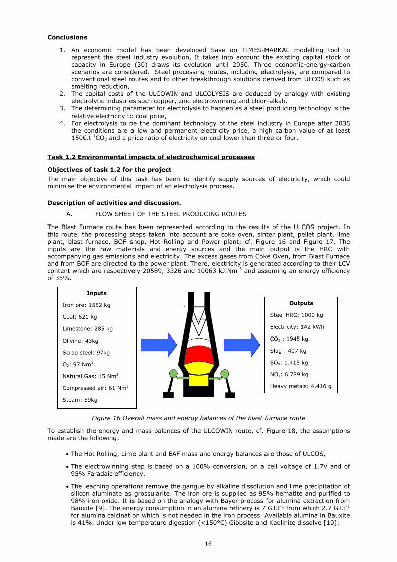
The Blast Furnace route has been represented according to the results of the ULCOS project In this route the processing steps taken into account are coke oven sinter plant pellet plant lime plant blast furnace BOF shop Hot Rolling and Power plant cf Figure 16 and Figure 17 The
inputs are the raw materials and energy sources and the main output is the HRC with accompanying gas emissions and electricity The excess gases from Coke Oven from Blast Furnace and from BOF are directed to the power plant There electricity is generated according to their LCV content which are respectively 20589 3326 and 10063 kJNm-3 and assuming an energy efficiency of 35
Figure 16 Overall mass and energy balances of the blast furnace route
To establish the energy and mass balances of the ULCOWIN route cf Figure 18 the assumptions made are the following
The Hot Rolling Lime plant and EAF mass and energy balances are those of ULCOS
The electrowinning step is based on a 100 conversion on a cell voltage of 17V and of 95 Faradaic efficiency
The leaching operations remove the gangue by alkaline dissolution and lime precipitation of silicon aluminate as grossularite The iron ore is supplied as 95 hematite and purified to 98 iron oxide It is based on the analogy with Bayer process for alumina extraction from Bauxite [9] The energy consumption in an alumina refinery is 7 GJt-1 from which 27 GJt-1
for alumina calcination which is not needed in the iron process Available alumina in Bauxite is 41 Under low temperature digestion (lt150degC) Gibbsite and Kaolinite dissolve [10]
Inputs
Iron ore 1552 kg
Coal 621 kg
Limestone 285 kg
Olivine 43kg
Scrap steel 97kg
O2 97 Nm3
Natural Gas 15 Nm3
Compressed air 61 Nm3
Steam 59kg
Outputs
Steel HRC 1000 kg
Electricity 142 kWh
CO2 1945 kg
Slag 407 kg
SOx 1415 kg
NOx 6789 kg
Heavy metals 4416 g
17
423
2981
980
41OElectrictyyElectricit
leachingleaching= 148 kWht-1
IronOxide = 211 kWht-1IronMetal
Then energy need for this operation is estimated to 200 kWhtHRC-1
3 SiO2 + Al2O3 + 3 CaO Ca3Al2Si3O12
The iron ore is ultra-finely ground from mean oslash50microm pellet feed to oslash10microm Input mineral particle size has the size of Pellet feed approximated by a F80 of 60microm The output mineral
particle size has a P80 between 10microm Ultra-fine grinding is carried out with a vertically stirred mill from Bradkenrsquos Metprotec mill Metsorsquos Detritor mill or Netschrsquos ISA mill [11] The specific electricity need for copper sulphide grinding Electricitysulphide= 45 kWht-1 Work index hematite 1268 kWht-1 Work index copper ore 1313 kWht-1 [12]
sulphideCopper
OreIron
sulphidegrindingWI
WIyElectricityElectricit = 43 kWht-1
Iron Ore = 66 kWht-1IronMetal lt 100 kWht-1
IronMetal
For the ULCOLYSIS route the main assumption is the thermal efficiency of the ULCOLYSIS cell The DC EAF has many common characteristics of a ULCOLYSIS cell it operates at the same temperature level of 1600degC it produces liquid steel it is driven by electricity and it does not involve cooling systems to protect the vessel lining The theoretical need to melts steel from room
temperature is 375 kWht-1liquidsteel on the other hand the energy need of a DC EAF is
conservatively lower than 550 kWht-1liquidsteel The thermal efficiency of 68 for DC EAF is applied
to an ULCOLYSIS cell Then the energy need to produce a unit tonne of liquid steel is 3864kwhtliquid steel
-1 cf Figure 19
18
Figure 17 Flow sheet of Blast Furnace route
19
Figure 18 Flow sheet of the ULCOWIN route and overall mass and energy balances
Outputs
Steel HRC 1000 kg
O2 273 Nm3
CO2 246 kg
Slag 182 kg
SOx 0633 kg
NOx 0 kg
Heavy metals 0 g
Inputs
Iron ore 1590 kg
Electricity 3489 kWh
Coal 28 kg
Limestone 147 kg
Natural Gas 56 Nm3
Compressed air 68 Nm3
Steam 4092 kg
20
Figure 19 Flow sheet of the ULCOLYSIS route and overall mass and energy balances
Inputs
Iron ore 1513 kg
Electricity 4028 kWh
Natural Gas 32 Nm3
Compressed air 41 Nm3
Steam 4092 kg
Outputs
Steel HRC 1000 kg
O2 307 Nm3
CO2 73 kg
Slag 69 kg
SOx 0633 kg
NOx 0 kg
Heavy metals 0 g
21
B LIFE CYCLE ANALYSIS OF THE STEEL PRODUCING ROUTES
The overall mass and energy balances have been used to estimate environmental efficiency of the
processes by Life Cycle Analysis These calculations have been carried out with GaBi [13] software
assuming a CO2 content of electricity of today European mix which amounts to 328gkWh cf Figure 20 European electricity mix
Figure 20 European electricity mix
The calculations give among other parameters the estimates of NOx SOx and CO2 air emissions results are presented in Figure 21
Figure 21 Results from LCA calculations carried out with GaBi software
NOx and SOx air emissions show significant differences between the conventional BFBOF route and the electricity-based ones For the conventional route the main contributors are the sintering plant and the hard coal production step which combine contributions represent more than 90 of the total cf Table III
22
Table III Air emissions from conventional route
Source of emission NOx SOx Comments
Sintering plant 84 74
Stemming from firing sections at the
sinter plant (use of fossil fuels) and combustion of sulphur compounds (from the coke breeze) in the sinter feed
Hard coal production 10 18 Mainly emitted by the transport phase from the mine to the consumer
Iron ore mining 4 4 Use of fossil fuels
Concerning the electrolytic processes namely ULCOWIN and ULCOLISYS NOx SOx and CO2 air emissions are essentially related to electricity generation (EU-27 grid) These figures have to be compared to the direct emissions deduced from the overall mass balances cf Table IV
Table IV Direct CO2 emissions from the processing routes
Direct CO2 emissions (kgCO2tHRC-1)
Conventional route 1945
ULCOWIN 246
ULCOLYSIS 73
These results emphasis that the environmental benefit of the electrolytic processes relies on the availability of low carbon electricity
C EXERGY BALANCE OF THE STEEL PRODUCING ROUTES
From the flow sheet described above it is possible to deduce the exergy balance of these processes The specific exergy content of the different inputs and outputs have been calculated and are represented in Table V Electricity is counted as pure exergy which assumes that it comes from renewable sources and not from the combustion of fossil fuels
Table V Exergy content of inputs and outputs in steel making routes
Input-Output Exergy
content Unit Calculation
Steel scrap iron 6645 MJkg-1Fe frac12Fe2O3rarrFe+32O2
G(25degC)= 6645 MJkg-1Fe
Coal anthracite 32833 MJkg-1C CO2rarrC+O2 G(25degC)=32833
MJkg-1C
Oxygen 0178 MJNm-3O2 pN [T(25degC)TN] ln(1021)
Natural gas methane 36490 MJNm-3CH4 CH4+2O2rarrCO2+2H2O
G(25degC)=818 kJmol-1CH4
Electricity 36 MJkWh-1 Pure exergy
Compressed air (10bars) 0255 MJNm-3 pN [T(25degC)TN] ln(101)
Steam (200degC) 0275 MJkg-1 H-T(25degC)S=275 kJkg-1H2O
Iron ore 0 MJkg-1 pure energy waste
Limestone Olivine slag 0 MJkg-1 pure energy waste
CO2 0 MJkg-1 pure energy waste
The exergy balances have been calculated as a state function depending only on input and output by combining the flow rates given in Figure 16 Figure 18 and Figure 19 by the specific exergy values of Table V The results are presented in Table VI
23
Table VI Results of the exergy balances of the steel making routes
Exergy input
(MJtHRC-1)
Exergy output
(MJtHRC-1)
Exergy balance
(MJtHRC-1)
Conventional route 21639 7155 14484
ULCOWIN 16648 6694 9954
ULCOLYSIS 16832 6700 10132
These results show that the electrochemical base processes have a significantly lower loss of exergy The high exergy losses of the conventional route come from the combustion of the off gas at the power plant There the transformation of the exergy content of carbon-based gases is carried out far from equilibrium which results into a low exergy efficiency If the electricity provided to the electrochemical processes was produced from fossil fuels it would be incurred with
this drawback Electrolytic processes preserve energy resources in their form of work as long as it does not involve a combustion step
Conclusions
A high environmental benefit and preservation of energy as work can be accomplished by electrolytic processes provided that they are supplied by low carbon electricity
24
25
WP 2 Development of the ULCOWIN process electrowinning iron in alkaline
solution
The electrowinning of iron is based on the reaction of decomposition of hematite into iron metal and oxygen by supplying energy as electricity
frac12 Fe2O3(s) Fe(s) + frac34 O2(g)
This reaction is carried out in an aqueous solution composed of sodium hydroxide and water Contrary to conventional electrowinning iron is not reduced as an ion but as a solid cf Figure 22
Figure 22 Reduction of iron oxide into iron metal by the ULCOWIN route
This particular chemical route supposes a specific electrowinning technology which departs significantly from conventional treatment of Ni Cu or Zn cf Table VII
10microm iirroonn ooxxiiddee
iirroonn mmeettaall
26
Table VII Comparison of electrowinning and ULCOWIN electrolysis processes
Electrowinning ULCOWIN
Metal produced Metal plates Metal plates
Cell gas configuration Open air cells with problems of mist dispersion in the atmosphere
Confined electrolyte without direct contact with the atmosphere
Temperature (degC) 60degC 110degC
Electrolyte composition ~1 molL-1 NaOH-H2O + solid particles oslash10microm Fe2O3
Anode material Ti coated with RuO2 Nickel
Inter electrode distance 60mm 10mm
Production rate 0024 Acm-2 (Ni EW) 0100 Acm-2
Cell voltage 35V (Ni EW) 17V
Metal harvesting Multiple electrode displacements starting sheet-stripping-resume deposition
One and quick operation of in-situ harvesting of the iron deposit
Co product No gas recovery Pure oxygen capture
Gas management Large inter electrodes gap for bubbles and separator as diaphragm
Gas bubbles are directed out of the
inter electrode gap by the effect of their buoyancy
Limit of electrode extension Electrode extension limited by bubble screening No extension limit by gas accumulation
Electrical contacts Current intensity limited by resistance in electrical contacts
Static and permanently connected electrodes
27
The overall objective of WP2 is to establish the conditions of efficient operation at large scale of the ULCOWIN process To reach this result the efforts are directed toward the following objectives
1 Improve Faradaic yield of the cathodic reaction by fundamental study of the iron reduction
and hydrogen evolution reactions
2 Study the impact of impurities (silica alumina) on the quality of the deposited iron and the yield of produced iron
3 Improve the yield of produced iron by improving the cell design and the operating electrolysis conditions such that the deposited iron will be harvested and not lost by detachment from the cathode
4 Improve the energetic efficiency of the reaction by decreasing the cell voltage owing to new anode material and design
5 Intensify the process to reach high production rates by incorporating process improvements in a laboratory pilot cell
6 Determine the conditions of scale up and design of industrial cells by simulation and extrapolation of the experimental results
Task 21 Cathode reaction mechanism
Objectives of task 21 for the project
A fundamental electrochemical study of the kinetics of the iron electrodeposition and the hydrogen evolution reaction will be carried out The kinetic parameters of these reactions will be determined
The influence of the main operating parameters such as current density particle diameter agitation and temperature on the Faradaic yield will be investigated The mechanism of growth of the metal plate will be studied in order to predict columnar and dendritic developments The morphology and the adherence of the deposited iron will be studied in detail under controlled laboratory conditions Also the role of impurities (silica alumina) will be investigated
Description of activities and discussion
A LABORATORY STUDY
Electrowinning of iron experiments have been carried out with an alkaline suspension of iron oxide particles in order to determine the effect of the main operating parameters on the efficiency of the
electrochemical reaction A dedicated experimental set up has been devised to produce the conditions of alkaline electrowinning in a small laboratory cell The cathode is a rotating disk that
can produce controlled conditions of convection by adjusting the revolving speed The electrochemical potential of the cathode is continuously measured it gives the thermodynamic driving force that produces the electrochemical reactions The composition of the electrolyte can be varied particularly interesting is the reactant iron oxide concentration
B KINETIC STUDY OF THE IRON AND WATER REDUCTION REACTIONS
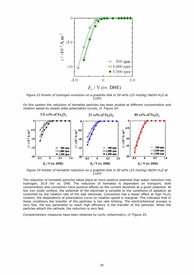
The hydrogen reaction has been suited in the 50 wt (25 molkg) NaOH-H2O electrolyte The cathode is a graphite disk which potential is referred to a platinum electrode This last electrode is termed Dynamic Hydrogen Electrode and defined as the potential corresponding to 1mA cathodic current The measures are obtained by steady state polarisation curve cf Figure 23 They show a slight sensitivity to convection and the start potential of hydrogen evolution at -018 V on graphite disk
28
Figure 23 Kinetic of hydrogen evolution on a graphite disk in 50 wt (25 molkg) NaOH-H2O at 110ordmC
On this system the reduction of hematite particles has been studied at different concentration and rotation speed by steady state polarization curves cf Figure 24
Ec V (vs DHE)
i times
10
3Am
-2
500 rpm
1000 rpm
1500 rpm
-05 0 05 10-20
-10
0
-15
-50
Ec V (vs DHE)
i times
10
3Am
-2
500 rpm
1000 rpm
1500 rpm
500 rpm
1000 rpm
1500 rpm
-05 0 05 10-20
-10
0
-15
-50
50 wt of Fe2O3
Ec V (vs DHE)
i times
10
3Am
-2
500 rpm
1000 rpm
1500 rpm
-05 0 05 10-20
-10
0
-15
-50
Ec V (vs DHE)
i times
10
3Am
-2
500 rpm
1000 rpm
1500 rpm
500 rpm
1000 rpm
1500 rpm
-05 0 05 10-20
-10
0
-15
-50
50 wt of Fe2O3
500 rpm
1000 rpm
1500 rpm
Ec V (vs DHE)
i times
10
3Am
-2
-05 0 05 10-20
-10
0
-15
-50
500 rpm
1000 rpm
1500 rpm
500 rpm
1000 rpm
1500 rpm
Ec V (vs DHE)
i times
10
3Am
-2
-05 0 05 10-20
-10
0
-15
-50
-05 0 05 10-20
-10
0
-15
-50
33 wt of Fe2O3
500 rpm
1000 rpm
1500 rpm
Ec V (vs DHE)
i times
10
3Am
-2
-05 0 05 10-20
-10
0
-15
-50
500 rpm
1000 rpm
1500 rpm
500 rpm
1000 rpm
1500 rpm
Ec V (vs DHE)
i times
10
3Am
-2
-05 0 05 10-20
-10
0
-15
-50
-05 0 05 10-20
-10
0
-15
-50
33 wt of Fe2O3
500 rpm
1000 rpm
1500 rpm
Ec V (vs DHE)
i times
10
3Am
-2
-05 0 05 10-20
-10
0
-15
-50
500 rpm
1000 rpm
1500 rpm
500 rpm
1000 rpm
1500 rpm
Ec V (vs DHE)
i times
10
3Am
-2
-05 0 05 10-20
-10
0
-15
-50
-05 0 05 10-20
-10
0
-15
-50
40 wt of Fe2O3
500 rpm
1000 rpm
1500 rpm
Ec V (vs DHE)
i times
10
3Am
-2
-05 0 05 10-20
-10
0
-15
-50
500 rpm
1000 rpm
1500 rpm
500 rpm
1000 rpm
1500 rpm
Ec V (vs DHE)
i times
10
3Am
-2
-05 0 05 10-20
-10
0
-15
-50
-05 0 05 10-20
-10
0
-15
-50
40 wt of Fe2O3
Figure 24 Kinetic of hematite reduction on a graphite disk in 50 wt (25 molkg) NaOH-H2O at 110ordmC
The reduction of hematite particles takes place at more positive potential than water reduction into hydrogen 359 mV vs DHE The reduction of hematite is dependent on transport both concentration and convection have positive effects on the current densities at a given potential At low iron oxide content the potential of the electrode is sensible to the conditions of agitation as controlled by the rotation rate of the disk electrode Convection has a lesser effect at high Fe2O3 content the dependence of polarization curve on rotation speed is marginal This indicates that in
these conditions the transfer of the particles is not rate limiting The electrochemical process is very fast the key parameter to reach high efficiency is the transfer of the particles When the particles attach the cathode the reduction is very fast
Complementary measures have been obtained by cyclic voltammetry cf Figure 25
29
-10 0 10 20
-10
0
10
100 mVsec
3rd cycle
1000 rpm
i
Am
-2
E V (vs DHE)
A
B
-10 0 10 20
-10
0
10
-10 0 10 20
-10
0
10
100 mVsec
3rd cycle
1000 rpm
i
Am
-2
E V (vs DHE)
A
B
Figure 25 Cyclic voltammetry with 40wt Fe2O3 in 50wt NaOH-H2O at 110degC
Peak A there is no multiplicity of peaks or humps which indicate a single process and then it is identified as direct reduction of Fe2O3 particle on cathode disk
Fe2O3 + 3H2O + 6e- rarr 2Fe + 6OH-
Peak B it is the reversible reaction namely dissolution of Fe in the electrolyte
Peak C it is the only possible anodic reaction which is oxygen evolution
4 OH- O2 + 2 H2O + 4 e-
C INFLUENCE OF OPERATING PARAMETERS
Deposits were produced on the rotating electrode systems the sample were weighted to measure the Faradaic efficiency It is maximal at 97 in conditions of high concentration 40 Fe2O3 and
relatively low current density 02Acm-2 The corresponding films are homogeneous until 03Acm-2 cf Figure 26 The the current density window for iron production is important ranging from 01 to
03 Acm-2 The cell voltage increases with the hematite concentration most probably because of a higher Ohmic drop in the electrolyte although cathodic polarisation decreases but to a much lower magnitude The cell voltage is highly sensible to the current density the cathodic polarisation contributes much to the change of voltage Current efficiency increases with the iron oxide content it reaches values above 95 The efficiency decreases significantly with high rotation speed indicating the detachment of deposit parts The current efficiency is also dependent with current density at high reduction rates the competing hydrogen evolution reaction may explain this loss of efficiency
30
Figure 26 Influence of mass transport concentration and convection on the cathodic efficiency
D MORPHOLOGY OF THE DEPOSITS
The crystal orientation of deposited iron in NaOH-H2O has been studied according to the current
density and to the concentration of iron oxide particles The deposits were produced with the rotating electrode system where the convective conditions were applied with a rotation of 1000 rpm and the resulting samples were analysed by XRD From these results the orientation index was derived according to the following relation
lkhI
hklI
lkhI
hklI
hklM
0
0
Where I (hkl) is the XRD intensity in experimental data
I0 (hkl) XRD intensity in JCPDS card
I (hrsquokrsquolrsquo) sum of intensity of (110) (200) and (211)
The results are presented on Figure 27 they show that all the deposits were -Fe films which
preferred orientation is the (211) plane Furthermore the most ordered Fe crystal is obtained at 40 wt of Fe2O3 for a production rate of 1000 Am-2
31
33 wt of Fe2O3
ordered
0
2
4
6
8
20 40 60
M(h
kl)
(211) plane
(200) plane
(110) plane
i times103 Am-2
33 wt of Fe2O3
ordered
0
2
4
6
8
20 40 60
M(h
kl)
(211) plane
(200) plane
(110) plane
i times103 Am-2
ordered
0
2
4
6
8
20 40 60
i times103 Am-2
M(h
kl)
(211) plane
(200) plane
(110) plane
40 wt of Fe2O3
ordered
0
2
4
6
8
20 40 60
i times103 Am-2
M(h
kl)
(211) plane
(200) plane
(110) plane
40 wt of Fe2O3
Figure 27 Orientation index of the iron deposits obtained from 1000 to 6000 A m-2 at 1000 rpm 33 wt and 40 wt Fe2O3
The iron films have cubic shape caused by -Fe (bcc) with preferred (211) plane direction
E INFLUENCE OF SILICIUM AND ALUMINIUM BASED IMPURITIES
Electrowinning of iron from alkaline solution containing ferric oxide silica and alumina was investigated by constant current electrolysis at 110 degC The deposits were analysed by scanning electron microscope (SEM) coupled with an energy dispersive X-ray spectrometer (EDS) The SEM images demonstrated that there were small gaps between columns which stacked up with six twin
crystals when the electrolyte silica and alumina content was up to 20 wt but EDS results showed that the purity was still high
Figure 28 SEM images of iron deposits with 10 wt SiO2 and 10 wt Al2O3 contents in the electrolyte
The feasibility was established of electrowinning of iron from iron ores containing 10 wt SiO2 and 05-1 wt Al2O3 in alkaline solution without any further solution purification Current efficiencies were typically gt 85 The deposits were column-like crystals and stacked up layer-by-layer
Compared with the previous results without impurities in the electrolyte the deposits were not so compact EDS results indicated that the deposits were of high purity in the bulk and with a small amount of impurities at the surface probably due to the contamination during the post-treatment of the deposits
Conclusions
1 In strongly alkaline solutions and cathodic conditions hydrogen evolution takes place on graphite electrodes Its reaction rate is sensible to agitation
2 Iron metal reduction happens at potentials 54mV more positive than hydrogen Iron reaction is favoured only for kinetic reasons The reaction is enhanced by higher particles concentration and by more intense agitation Voltammetry potential scanning indicates that hematite reacts in one-step to iron metal without intermediate species The electrochemical process is very fast the key parameter to reach high efficiency is the transfer of the particles to the cathode
32
3 Maximum Faradaic yield is obtained with 40wt of Fe2O3 in 50wt NaOH-H2O at 110degC
1000 rpm and 02 Acm-2 it reaches 97 The current density window for efficient iron production extends from 01 to 03 Acm-2
4 The iron films have cubic shape related to -Fe (bcc) structure and they grow as columnar structures toward the preferred (211) plane direction
5 Compact and homogeneous deposits can be obtained with high concentration of particles and low current density
6 Silica and alumina impurities do not compromise the Faradaic yield but loosen the deposits Al2O3 showed stronger influence than SiO2 on iron electrolysis
Exploitation and impact of the research results of task 21 for the project
S H Tang and G M Haarberg Electrowinning of Iron from Alkaline Solution ECS Transactions 28 (6) 309-315 (2010) 10114913367923 copy The Electrochemical Society
M Tokushige OE Kongstein GM Haarberg Abstract 3295 Honolulu PRiME 2012 copy 2012 The Electrochemical Society Crystal Orientation of Iron Produced by Electrodeoxidation of Hematite Particles
Task 22 Anode material
Objectives of task 22 for the project
The main objective is to study oxygen evolution reaction in order to develop reliable material candidates for electro catalyst anode electrodes The deviation from reversibility in the electrolysis
process is maximum for the anodic oxygen evolution reaction Decreasing this overvoltage is the most promising route to improve energy efficiency of the process The developed solutions will be incorporated in the laboratory pilot cell and test them They should be cheap and simple enough to be consistent to up scaling of the process
Description of activities and discussion
A OXYGEN EVOLUTION REACTION CATALYSIS
The anodic reaction of oxygen evolution represents the most important penalty to the energy efficiency of the ULCOWIN process Most of the energetic efficiency improvements are expected to be obtained by refining the anode system In the context of the ULCOS project these materials ought to be from sustainable resources
The main deviation from ideality during iron making by electrochemical route is the synthesis of oxygen gas at the anode The ability to reduce the kinetic resistance for oxygen synthesis is paramount to high-energy efficiencies Indeed most of the energy loss takes place in the anodic
reaction of oxygen evolution Lowering this overpotential represents one of the most important sources of energetic improvement of the ULCOWIN process With nickel anode the overpotential is estimated at ca 04V The reaction of water oxidation in alkaline solution on the anode surface involves the hydroxide anions as reactants NaOH and water are singlet molecules with paired electrons which results in diamagnetic properties while oxygen is a triplet molecules with two unpaired electrons spin parallel and is therefore paramagnetic This means that the progress of the reaction supposes the generation of a magnetic moment However chemical reactions are spin
selective they allow reactions for which magnetic moment should be conserved and more generally symmetry must be conserved in all chemical reactions Then catalysts may decrease this barrier and lower the overvoltage
4 OH- O2 + 2 H2O + 4 e-
There are several possible approaches to develop electrocatalysts
1 Metals such as nickel and cobalt are known to favour the OER They combine
electrochemical durability in alkaline conditions and near the oxygen evolution potential but this may be obtained at potential values well above the thermodynamic stability of the metallic support and relying on electrochemical passivation exerted by oxide or hydroxide scales Thus the true electrocatalytic activity is dependent on the properties of these scales and their redox changes near or slightly above the oxygen evolution potential
2 Metal oxide particles suspended in the electrolyte Since the early beginning of the ULCOS project the hematite particles in suspension have shown to produce a catalytic effect on the oxygen evolving reaction This has been observed for systems where hematite particles are maintained in suspension in the electrolyte and in which the anode is dipped These
33
compounds may be selected according to their redox behaviour having a redox transition just above the OER may be helpful to this reaction
3 Metal oxides incorporated in a metal matrix as cermets In this configuration the metal
oxide catalyst would not be dragged by the electrolyte and would not interfere with the cathode process The direct mechanosynthesis method of plastic deformations was used to incorporate catalysts on Ni or related alloys anode Catalyst and nickel metal particles are firstly mixed and then they are pressed on the nickel anode surface to be incorporated by plastic deformation The electrode is then annealed and polished before electrochemical testing This method was applied to insert Sr09K01FeO3-d PrOx CeO2 The main figure of merit of this technique is to facilitate manufacturing and shorten the time of sample
production Particles such as carbon nano tubes and PrOx can be incorporated by electrochemical deposition of nickel with a composition derived from Wattsrsquos baths
4 Complexing agents which increase the dissolution of iron
B INVESTIGATED SOLUTIONS
Table VIII Solutions for anode materials
Name of candidate compound
Chemical composition
Influence on
oxygen evolution reaction
1 - Metals Nickel metal Ni reference
Cobalt metal Co +
Nickel cobalt alloys 51 wt by electrodeposition
+
2 - Particles in suspension
Micro hematite -Fe2O3 +
Nano maghemite -Fe2O3 +
Nano magnetite Fe3O4 +
Manganese oxide Mn2O3 and MnO2 -
Strontium peroxide SrO2 -
Ceria CeO2 -
Praseodymium peroxide PrOx -
3 -Incorporated
particles in metal matrix by plastic deformation
Hematite -Fe2O3 +
Strontium ferrate Sr09K01FeO3-d +
Praseodymium nickelate Pr2NiO4 =+
Praseodymium oxide PrO2 =
Ceria CeO2 +
Cobalt spinel Co3O4 +
carbon nanotubes CNT +
BSCF Ba05Sr05Co08Fe02O3-d +
4 - Complexing
agent
Triethanolamine C6H15NO3 + on the
anode but - on the
cathode
34
C RESULTS OF THE EXPERIMENTAL INVESTIGATIONS
There is no better metal than an alloy of NiCo 51 wt produced by electrodeposition cf Figure 29
Figure 29 Kinetics of the oxygen evolution reaction according to cobalt content
There is no better metal oxide suspended particles than nano magnetite but hematite efficiency improvement is close cf Figure 30 These results stress that an anode is not just a material that can be developed without considering the chemical environment brought by the electrolyte Compounds present in the electrolyte interact with the anode reaction if properly engineered they can contribute to lower the resistance on the anode interface The iron oxide is electrochemically active on the anode which represents a considerable advantage in terms of lean chemical
inventory This represents a conspicuous aspect of the ULCOWIN process where the main reactant ie iron oxide contributes to lower cell voltage on both electrodes
Figure 30 Kinetics of the oxygen evolution reaction according to iron oxide
Plastic deformation is a versatile approach to incorporate different catalysts in Ni-based anodes As incorporated particles -Fe2O3 Sr09K01FeO3-d (SKFO) CeO2 Pr2NiO4 PrOx Ba05Sr05Co08Fe02O3-d
(BSCF) they give positive results However this may still depend on the conditions of preparation for example SKFO catalysts as shown of the effects of high energy milling used to obtain intimate mixture of the SKFO catalysts with Ni powders before plastic deformation A plausible cause for this may be the partial degradation of the catalyst and onset of NiO during the step of recrystallization after plastic deformation of these NiSKFO electrodes Another reason may be
related to partial leaching of the alkali earth or alkali components even under strongly alkaline conditions Ceria improvement is consistent with the known catalytic activity of ceria in other
10 M NaOH
Fe2O3
(ore)
12 mMHFeO2
-
Fe2O3rarr
maghrarr
Fe3O4
00
02
04
06
08
05 06 07
j (A
cm
2)
E vs HgHgO 6M (V)
0
5
10
15
20
055 060 065 070 075
E vs HgHgO 1M (V)
j (m
Ac
m2)
Ni plate
Ni 100 wt
NiCo 1001 wt
NiCo 201 wt
NiCo 101 wt
NiCo 51 wt
NiCo film (from
electrodeposition
method)
35
electrochemical oxygen processes including the oxygen storage ability of ceria for high
temperature processes When compared to the other catalyst freshly prepared BSCF give the best result However prolonged exposure to anodic conditions degrades the properties
Figure 31 Voltammograms of Ni-based anodes in 10 KOH without or wide Sr09K01FeO3-d (SKFO)
catalyst inclusions Electrodes with references NiSKFO and Ni pellet were obtained by plastic deformation Other electrodes were commercial Ni plates
The most active catalyst at high current density is spinel particles of cobalt as shown on Figure 32
SKFO
BSCF
Co3O4
Ni
Ni(SKFOb
(51)
0
10
20
30
04 05 06 07 08
E (V
) v
s H
gH
gO
1 M
E vs HgHgO (V)
1 M NaOH 25 ordmC
j
(m
Ac
m-2
)
Figure 32 Voltammograms of the anode material candidates prepared by plastic deformation in 1M NaOH at 25ordmC at 1 mVs for NiBa05Sr05Co08Fe02O3-d (BSCF) NiSr09K01FeO3-d (SKFO)
NiCo3O4
Triethanolamine is known to be a good complexant agent of iron in alkaline conditions The addition of this compound has a strong positive effect on the kinetic of oxygen evolution when iron oxide particles are present Another remarkable feature revealed by anodic polarization in simultaneous presence of hematite suspension and TEA is the near vertical up rise of current density almost independently of increase in electrode potential this is confirmed by
measurements at lower temperatures and suggests in-situ activation of active species cf Figure 33 Thus one may assume that Fe-based species responsible for enhanced oxygen evolution in the presence of hematite suspensions are further activated in presence of TEA possibly by complexation
Ni plateNi plate+
10gl CeO2
Ni pellet
NiCeO2
pellet
00
02
04
06
04 05 06 07 08
j A
cm
2
E vs HgHgO (V)
36
Figure 33 Effects of triethanolamine (TEA) on oxygen evolution in Ni anodes with and without Fe2O3 suspensions
However the beneficial effect is associated with a detrimental effect on the Faradaic yield of the cathode reaction cf Figure 34
Figure 34 Effects of TEA and hematite contents on cathodic Faradaic efficiency
C APPLICATION TO THE ULCOWIN VERSION Ndeg2
A practical solution must be deduced to be applied to the ULCOWIN technology The electrocatalytic layer has to check specifications which stem from the ULCOWIN process and from the purpose of efficiency improvement
To implement the electrocatalytic properties the nickel lamella had to be coated with a 20microm of cobalt layer A laboratory electroless operation has been set up The electroless bath composition
has been chosen based on literature and experiment The surface preparation has been adapted to the treatment of nickel substrate with an alkaline degreasing and a strong descaling operation
0
20
40
60
80
100
-11 -09 -07 -05 -03 -01
Cu
rren
t eff
icie
ncy (
)
j (Acm2)
50gl Fe2O3
50gl Fe2O3 + 03M TEA
100 gl Fe2O3 + 01 M TEA
100 gl Fe2O3
90ordmC
10M NaOH90ordmC
100 rpm03M TEA
100gl Fe2O3
20ordmC
50ordmC70ordmC
00
01
02
03
04
05
040 050 060 070 080 090
j (A
cm
2)
E vs HgHgO (V)
Niref
100glFe2O3100gl Fe2O3
+03M TEA
03M TEA
Ni anodes10M NaOH
90ordmC100 rpm
00
01
02
03
04
05
040 050 060 070 080
j (A
cm
2)
E vs HgHgO (V)
37
Figure 35 Electroless plating vessel of the nickel lamellae
Six treatments were necessary to plate the 121 lamella The first three treatments were unable the proper thickness during the following three treatments the accurate choice of composition and temperature delivered cobalt layers of 20microm accordingly to the initial specifications The thickness of the cobalt layer is measured by mass difference assuming a compact deposit The conditions to obtain the right thickness are a temperature maintained at 72degC except at the start of the plating
process where an initial strike may be necessary for nucleation and a hypophosphite concentration ca 05M
Conclusions
1 Suspended hematite particles contribute to lower the anodic overvoltage this effect is already applied in the ULCOWIN technology
2 Metal cobalt is the most readily available catalyst It can be prepared by depositing eleclectroless cobalt on nickel plates This system constitutes the ULCOWIN Version Ndeg2 solution for catalytic anode
3 A more efficient solution would be to incorporate cobalt based oxide spinels in a nickel matrix that be applied in further development of the ULCOWIN technology
Exploitation and impact of the research results of task 22 for the project
JF Monteiro JC Waerenborgh AV Kovalevsky AA Yaremchenko JR Frade Synthesis of Sr09K01FeO3-d electrocatalysts by mechanical activation Journal of Solid State Chemistry 198 (2013) 169ndash175
Yu A Ivanova J F Monteiro A L Horovistiz D K Ivanou D Mata R F Silva J R Frade Electrochemical deposition of Fe and FeCNTs composites from strongly alkaline hematite
suspensions J Appl Electrochem DOI 101007s10800-015-0803-6
Task 23 Anode design
Objectives of task 23 for the project
The principal target of the anode design is the removal of oxygen gas generated during the process in the gap between anode slats as quickly as it is produced By means of CFD simulations the performance of anode shapes is numerically tested and optimised before being experimentally tested The anode system combines gas removal property with unifomity of the current distribution on the cathode It is a key element to improve the energy efficiency of the cell It can contribute to lower the cell voltage by reducing the gap and by limiting the screening effect of the oxygen gas bubbles These
properties determine the maximum current density and therefore the specific production rate Furthermore the solution deduced should be compatible to further upscaling of the process
Description of activities and discussion
The iron making reaction of iron oxide decomposition is based on the separation of oxygen gas
from iron metal Organising an efficient separation is paramount to the efficiency of any iron making process and electrolysis is no exception To this respect the anode is one of the components of the cell which is supposed to contribute to that effect Its main task is to flow electrical current coming from the current leads spread it over the cathode and gather in a single channel the oxygen gas produced on it To carry out this operation with the maximum efficiency the current must be distributed as evenly as possible the gas must be capture as early as possible and electrical charges must be transferred from one electrode to the other with the least
resistance The ULCOWIN technology addresses this task with lamella stacked normal to the cathode
38
A CURRENT DISTRIBUTION SIMULATION OF THE ANODE SYSTEM
A two dimensional symmetric and periodic scheme is assumed as the longitudinal crosscut of the anode The simplest configuration is chosen it is defined by three geometrical parameters ldquoerdquo half
thickness of the lamella ldquolrdquo half wavelength of the scheme and ldquogrdquo the inter-electrode distance cf Figure 36 This resulting lamellar structure is selected to take advantage of the high anodic overpotential A large anodic overpotential tends to level and distribute the current along the anode surface According to the theorem of Buckingham the geometry can be described without loss of generality by two parameters The first is the openness (l-e)l and the second the relative wavelength of the periodic structure ldquolgrdquo
cathode
electrolyte
anode
g
e
l
cathode
electrolyte
anode
g
e
l
Figure 36 Design principle and notation for the anode
The relations relating the geometry to the electrical potential are given by the Schwarz-Christoffel theorem which relates the complex potential ldquordquo to the geometry ldquozrdquo
k|snk
k1
k|ωarcsinFkKikKω 12
hnkk|snarcsinz 2
The figures of merits of this configuration are evaluated according to the deviation from uniformity of the current distribution on the cathode ldquordquo the channelling of the gas ldquoCrdquo and the Ohmic resistance
ldquoRrdquo which can be deduced without calculating the current distribution
The deviation from uniformity on the cathode noted ldquordquo
ds1j
j
l
1
cathode mean
The fraction of current exchanged by the anode on its face normal to the cathode ldquoCrdquo
currentoverall
currentsideC
The Ohmic resistance ldquoRrdquo
meanjg
VR
They can be deduced from the geometric parameters Their constant values curves are drawn on Figure 37 The points are the locations of the performances of the different versions of the ULCOWIN cell The graph shows that the most interesting solutions are located at the upper left part of the diagram There the anode is made of thin lamella
39
Figure 37 Mapping of the non-uniformity conductance and channelling according to the dimensionless geometric parameters of the cell
The solutions are deduced by inverse approach It consists in choosing a performance of the anodic system and to deduce the dimensions of the system to produce these performances
The solutions are checked by direct simulations they are conducted with ELDEP code It is based on finite element method It determines the potential and stream function distributions according to the conduction properties of the media and interfaces The assumptions are the followings
Anode and cathode are equipotential there is no Ohmic loss in the metal phase compared
to the electrolyte
The dimensions those selected previously
The conductivity of the electrolyte is uniform = 15 Scm-1
The anodic kinetic is described by a Tafel ldquotyperdquo kinetic relation with a slope of b= 0045Vdecade-1 and an exchange current density of j0 = 215 10-7 Acm-2
TR
F6891exp10152cmAj 72
Although the secondary current distribution is much different on the anode compared to primary assumptions the results shows that it is not the case on the cathode The ULCOWINv20 anode has been designed to increase the performance of the cell
ULCOWINv1
ULCOWINv20 and v25
ULCOWINv3
40
ULCOWIN version Ndeg2
Figure 38 Primary and secondary current distribution on the ULCOWINv2 anode
primary
40
60
775
225
secondary
41
B CFD SIMULATIONS OF ULCOWIN VERSION Ndeg2 CELL ANODE SYSTEM
CFD simulations have been carried out by Tecnalia for the geometry of the laboratory pilot cell
ULCOWINv2 proposed by ArcelorMittal The cell has an inclination of 45ordm with a plate cathode and
slats anode to help in the particle transport with little accumulation and to obtain the highest buoyancy force for the oxygen bubbles
Due to the symmetry of the geometry only half of the cell is considered for CFD simulations The
generation of oxygen along the anode plates is analysed by considering a bubble size of 100 microns The target of the design is the removal of the oxygen gas generated during the process in the gap between anode plates as quickly as it is produced The coalescence of the bubbles is not considered A general view of ULCOWINv2 geometry is depicted in Figure 39
Figure 39 General view of CFD model of ULCOWIN version Ndeg2
Two phases have been defined the primary phase is the slurry and the secondary phase is the oxygenrsquos bubbles Oxygen generation on anode faces has been determined according to current
distribution The plate height has been divided in four sectors and a constant mass flow rate has
been imposed at each one Regarding the volume fraction of gas at the gas pipe outlet when higher velocities of the slurry at the inlet are considered oxygen bubbles generated at the anode bottom faces are drawn by the slurry towards the outlet and therefore the oxygen volume fraction
at the gas pipe outlet decrease (Table IX)
Table IX Volume fraction of O2 at Slurry Outlet and Gas Pipe Outlet
Volume Fraction of O2 at
Slurry Outlet Gas Pipe Outlet
Bubbles Size 100 microns 100 microns
Velocity at the Inlet
01 ms 112e-5 00609
03 ms 281e-4 00492
05 ms 125e-3 00346
In Figure 40 and Figure 41 are depicted the isosurfaces of volume fraction of gas equal to 01 (blue) 04 (green) and 08 (red) for a velocity inlet of 01 ms It can be observed that lower oxygen volume fractions are obtained at first anode gaps because of the higher velocities at those
42
locations The volume fraction of oxygen in the gas collection pipe decreases when velocity at the
inlet increases Higher volume fractions are achieved at the bottom end of the laboratory pilot cell because the slurry draws bubbles
Figure 40 Contours of volume fraction of oxygen (in red values gt 001) in symmetry plane for v=01ms and oxygen bubbles of 100 microns
Figure 41 Contours of volume fraction of oxygen (in red values gt 001) in symmetry plane for v=03 ms and oxygen bubbles of 100 microns
C DEVELOPMENT OF THE ULCOWIN VERSION Ndeg3 ANODE SYSTEM
As seen by comparing primary and secondary cases cf Figure 42 the amount of current exchanged on the face normal to the cathode is significantly increased from 60 to 944
The ULCOWINv3 anode is expected to provide additional properties that will facilitate the scale up development of this process
In red colour gas vf gt001
01 ms amp 100 microns
In red colour gas vf gt001
03 ms amp 100 microns
43
1 The performance are significantly improved in current distribution uniformity channelling of the gas and conductance of the current
2 A throttling effect of the gas to foster bubble coalescence to increase buoyancy by
throttling in a 3D effect the evolving gas A lower hydraulic residence time of the gas bubble is expected The screening effect of the bubbles toward the electrical flow will be decreased
3 The anode is made in steel to be cheap and subsequently coated with cobalt or a new electrocatalytic material The electroless technique proved that cobalt can be applied on any shape The thin lamella can be machined by Electro discharged Machining
4 The shape of the anode is also designed by constructal method the dimensions are chosen to produce a uniform Joule effect in the anode This is supposed to involve the least amount of matter to perform the distribution of current
44
ULCOWIN version Nordm 3
Figure 42 Primary and secondary current distribution on the ULCOWIN Version ndeg3 anode design
primary
60
40
944
56
secondary
45
D CFD SIMULATIONS OF THE ULCOWIN VERSION Ndeg3 ANODE SYSTEM
CFD simulations have been carried out by Tecnalia to develop the design of version Ndeg3 of the laboratory pilot cell of ULCOWIN The main differences of this previous design are
A new anode geometry
The new current distribution on these anode slates Oxygen generation at anode faces has been determined according to the current distribution data provided by ArcelorMittal for
each anode plate
Chevrons machined in the top cover have the same thickness as the anode to top cover distance so they produce a barrier to the fluid flow
Central channel is enlarged from down to top
The boundary conditions are the same ones used for the ULCOWIN version Ndeg2 It is important to mention in connection with the boundary conditions that the pressure boundary condition at each outlet has been fitted to reproduce the operating conditions at the beginning of each laboratory
test ie to achieve that the slurry does not flow through the gas pipe before the differential potential between electrodes is applied
Four cases have been run two cases are presented for different mean slurry velocities at the inlet (03 ms and 01 ms) In all cases the same O2 bubble size of 100 microns has been considered The ASCoPE project has shown that this diameter of bubbles is close to what is observed on experimental simulation devices Decreasing the mean flow velocity modifies completely the gas flow the buoyancy effect of the bubbles overcomes the dragging effect of the slurry flow and all the gas leaves the cell through the gas outlet The transition between the two flow patterns occurs between 01 and 03 ms
Figure 43 General view of CFD model of ULCOWIN version Ndeg3
46
Upper Part
(upstream)
Middle Part
Lower Part
(downstream)
Figure 44 Volume fraction of O2 Symmetry plane Case 01 ms amp 100 microns (in red colour volume fraction gt 15) for ULCOWIN version Ndeg3
47
Upper Part
(upstream)
Middle Part
Lower Part
(downstream)
Figure 45 Volume fraction of O2 in symmetry plane for case 03 ms amp 100 microns (in red colour volume fraction gt 5) for ULCOWIN version Ndeg3
For the lowest operational velocity analysed (01 ms) all the CFD simulations predict that almost all the oxygen generated escaped through the gas outlet According to the results of CFD simulations the mean velocity of slurry at the inlet is a critical parameter to achieve that the gas generated will be evacuated through the gas pipe Therefore the most obvious consequence is to operate the cell at low velocities
48
Table X Percentage of O2 gas amp slurry at each outlet for ULCOWINv3 with and without chevrons
Geometry Analysis case
Phase Slurry outlet
Gas outlet Vel inlet Bubble size
ULCOWINv3_FINAL
03 ms 100
microns
gas (O2) 6683 3317
slurry 7619 2381
025 ms 100
microns
gas (O2) 1513 8487
slurry 7273 2768
02 ms 100
microns
gas (O2) 453 9547
slurry 7348 2664
01 ms 100
microns
gas (O2) 089 9911
slurry 6953 3047
Conclusions
1 Two anode systems Ndeg2 and Ndeg3 have been drawn to conciliate uniform current distribution on the cathode low Ohmic resistance between the electrodes and recovery of gas bubbles generated at the anode These two solutions are close to what is ideally conceivable
2 The interaction of these two designs with the circulating electrolyte has been tested by CFD simulations The mean slurry velocity at the inlet is a key parameter because it determines the direction of the gas flow generated at the anode plates
Both solutions have been machined and produced They may be upscale to participate in a further development of the process cf
3 Table XI
Exploitation and impact of the research results of the task 23 for the project
Herveacute Lavelaine de Maubeuge Influence of geometric variables on the current distribution uniformity at the edge of parallel plate electrodes Electrochimica Acta 56 (2011) 10603ndash 10611
49
Table XI Anode technology evolution of the ULCOWIN technology
ULCOWIN version Ndeg1
(ULCOS)
ULCOWIN version Ndeg20
(IERO)
ULCOWIN version Ndeg25
(IERO)
ULCOWIN version Ndeg3
(IERO)
Technical drawings
Actual workpieces
50
Task 24 Cathode material
Objectives of task 24 for the project
The objective of this task is to identify a cathode material compatible with the ULCOWIN process and
with the mechanical strength required by the fastening system of an enclosed cell This material should ease the harvesting of the produced iron plates Its availability and cheapness should be compatible to upscaling for further development of the process
Description of activities and discussion
The previous version of the ULCOWIN cell included graphite as the cathode material It proved
unsatisfactory due to its porosity its low mechanical strength and its low electrical conductivity These inadequate properties have conducted to leakage and eventually short-circuiting during operation Alternative materials to improve the performance of the next version of the ULCOWIN cell are investigated To select this material the required specifications of the cathode material have been identified
1 The material should guarantee safe electrolysis operation Particularly no spontaneous and energetic chemical reaction between the cathode and the building materials involved in the cell may happen The insulating material which contribute to the channelling of current
and to the tightness of the cell are made in fluoride plastic
2 It should not alloy with iron in order that the iron deposit does not weld on the cathode The iron deposit must be separated from the cathode substrate without wear
3 It should be electronically conductive in order to ease the flow of current and minimise Ohmic loses
4 It should resist to the high temperature alkaline chemical environment either by immunity or either by passivity Even though the cathodic polarisation protect the metal from
corrosion resistance to oxidation in the electrolyte is necessary during filling and rinsing operations
5 Good adherence with the deposit in order that the deposit does not slip from the cathode during electrolysis
6 Mechanical strength to withstand fastening conditions necessary to tighten the cell
7 High overpotential for hydrogen evolution in order that this competing reaction does not compromise the efficiency at the start of the deposit growth
8 The elements should be naturally available in order not to compromise the environmental efficiency of the process This property is a rough estimate of the sustainability and cheapness of the material
9 The elements should be available in order to not compromise the environmental efficiency of the process
There are a limited number of elements from the classification which check the second criterion Mg La Cu Ag Au In Pb and Bi The fourth criterion is checked by thirteen elements according to Pourbaix diagrams Gold thanks to immunity Silver Osmium and Copper thanks to cathodic immunity alone Niobium Tantalum Hafnium Titanium and Magnesium thanks to passivity alone
Platinum Rhodium Palladium and Bismuth thanks to passivity and cathodic immunity Then Gold Silver Copper Magnesium and Bismuth combine the two criteria The comparison of electrical resistivity indicates that bismuth is far from the performance of the other elements cf Table XII
51
Table XII Electrical resistivity of candidate cathode materials
Element Electrical resistivity (m x10-8)
Mg 405
Cu 1534
Ag 1467
Au 2051
Bi 1068
C 1375
Fe 961
Ni 603
According to corrosion data Mg Cu and Ag are an order of magnitude more resistant than iron but also an order of magnitude less than nickel which represents the reference solution for corrosion resistance in alkaline solutions cf Table XIII
Table XIII Corrosion rate of candidate cathode materials
Element Corrosion rate (mmannum-1) Testing conditions
Mg suitable
Cu 014 NaOH 50 150degC
Ag 013 NaOH 75 480degC
Fe 18 NaOH 73 115degC
Ni 0027 NaOH 50 130degC
CuNi 9010 005 NaOH 73 105degC
By far magnesium is the most abundant conversely silver and gold are scarce cf Table XIV Furthermore plating on a noble metal like gold and silver may compromise the first step of
electrocristallisation The nucleus of iron will be under galvanic coupling with the noble bare metal The intensity of this phenomenon is all the more important that the nucleus is small and it evolve toward the dissolution of iron This could create a barrier at the early start of the deposition process
Table XIV Element abundance in Earthrsquos crust
Element mgkg-1
Iron 563 x 104
Magnesium 233 x 104
Carbon 200 x 102
Nickel 75 x 101
Copper 55 x 101
Silver 7 x 10⁻²
Gold 4 x 10⁻³
The results of the application of the required specifications are copper and magnesium However copper is oxidable in alkaline solution cf Figure 46 The corrosion data indicate that a significant improvement can be obtained with alloying with nickel
52
Figure 46 Pourbaix diagram of carbon magnesium and copper at 25degC
Experimental tests on small laboratory devices have been carried out and show that iron deposits on magnesium and on cupronickel in the conditions of the ULCOWIN process are uniform and compact cf Table XV
Table XV Cathode material solutions
Copper Magnesium Graphite
Tensile strength
~300MPa 220~270 MPa 29 MPa
Experi
menta
l te
sts
Copper-Nickel 30
Cupronickel is more convenient to implement than magnesium Magnesium is chemically reactive toward fluoropolymers like Teflon Mixed as fine powder the reaction is explosive Moreover magnesium corrodes with neutral solution which is used for rinsing and cleaning of the cell The ULCOWINv2 is designed to accept both solutions The cathode is held with a non-reactive thermoplastic such as PEEK and a rinsing circuit has been purposely built to rinse the cell with a slightly alkaline solution
Conclusions
Solutions for cathode material have been identified by a systematic approach three can be selected based on Cupronickel10 magnesium and graphite They all can contribute to the development of the ULCOWIN technology and are tested on the laboratory pilot
Task 25 Intensification of the process
Objectives of task 25 for the project
The development of the process requires to investigate the main controllable parameters which are the concentration of particles in the suspension the temperature of electrolysis the current density the alkalinity of the aqueous medium the time of deposition ie thickness of the iron
deposit the purity of the iron oxide the diameter of the particles and the velocity of the suspension The effect of these parameters on the compactness ie roughness of the deposit the cathodic Faradic efficiency the flatness of the deposits the purity of the iron plates are necessary to estimate a further scale up of the process These results will be obtained by operating a laboratory pilot cell The improvements deduced from ULCOS and from the results of the other tasks will be incorporated in new versions of the pilot cell The conditions of maximum
53
intensification ie low gap high current density length of the cathode will be deduced The results
obtained in the laboratory pilot cell will be complemented with the knowledge provided by CFD simulations of the experimental work
Description of activities and discussion
This Task represents the main effort of the IERO project It is carried out at ArcelorMittal Maiziegraveres where a pilot facility has been devised during the ULCOS project (2004-2010) The objective is to
provide an efficient simple to operate and cheap technology for iron electrowinning It incorporates the results obtained by the other Tasks of the work package The operating conditions are derived from Task 21 the anode material is defined by the University of Aveiro in Task 22 the anode for gas generation and extraction is designed in Task 23 by Tecnalia and Task 24 has identified cathode materials
A LABORATORY PILOT DEVELOPMENT
The ULCOWIN pilot has been modified to accommodate the specific involvement of slurry made of the mixture of iron oxides particles and a liquid sodium hydroxide solution Several improvements of the ULCOWIN pilot have been accomplished
The tightness between the pipes of the electrolyte was leaking To ensure better tightness
the cylindrical joins were changed with conical joins and the screw were wrapped with Teflon tape
An additional circuit has been developed to rinse the cathode without mixing with the electrolyte If magnesium based cathode is involved in the cell then it must be rinsed with alkaline water to limit corrosion of the magnesium A tank has been designed V= 160 L to prepare the solution at the right pH 12 and to flow it in the cell circuit
Pump reliability has been increased by inserting filter and expansion joints both at the
suction and discharge sides The filter protects the pump from incidentally introduced pieces such as cable ties or chunks of iron deposit which may injure the pump shaft The expansion joint gives some clearance for tight bolting of the pipe flanges
Head loss measured by differential pressure is positioned to take into account the settling of particles that could compromise the measurements It is positioned above pressure connections to avoid sedimentation It is equipped with additional valves to insure gas purging and water rinsing
All the stagnation zones of the slurry circuit have been eliminated in order to avoid clogging by particle sedimentation The rinsing circuitry was also clogged by the settling of the iron oxide particles The rinsing circuitry of the pilot is separated from the main flow circuit by a valve This valve is position below the main flow pipe in the short part the particles settle and produce clogging Now the valves are positioned above
The solid deposit also clogged the sampling valve Sampling of the electrolyte is done owing to a small valve positioned at the lowest part of the pilot However it was downward
oriented with subsequent particle settling to overcome this shortcoming it is now positioned upward
The output gas is analysed to measure both its oxygen and hydrogen contents these figures will provide almost instantaneous conditions of electrolytic flow and electrochemical reactions Short circuit or loss of Faradaic efficiency by hydrogen production can be diagnosed
The heat insulation of the cell will be completed with a system based on pieces of polyisocyanurate
A thermal sensor measures the room temperature it completes the necessary data to evaluate the heat balance of the pilot in live
All these modifications are illustrated on Table XVI
54
Table XVI Pilot improvements to accommodate new ULCOWIN cell
Improved pump reliability Elimination of stagnation
zones Sampling and draining of
the electrolyte Additional thermal probe Tightness of pipe joining
Dra
win
gs o
r
pre
vio
us
conditio
ns
Imple
menta
tion
Cathode rinsing system Pressure drop measurement
Gas liquid separator Hydrogen gas analyser Cell heat insulation
Dra
win
gs o
r pre
vio
us
conditio
ns
Imple
menta
tion
55
B ULCOWIN VERSION Ndeg2 TECHNOLOGY
During the ULCOS project (2004-2010) ULCOWIN version Ndeg1 pilot cell has been operated to
produce iron samples During these experiments electrolyte leakage has been observed in
different locations of the cell Particularly detrimental to the process was the loss of tightness at the cathodic current leads with the ensuing suspension flow through them during testing Examination of the cell during disassembling showed that the different workpieces of the cell where not maintained tight This phenomenon is all the more damaging to the process that the electrolyte is conductive Short circuit between the cathode and the overall cell structure may have taken place The settling of conductive iron oxide particles worsen the situation short circuit can turn electronic which is far more efficient to flow current than ionic conduction That could explain the
rather disappointing Faradaic yield and the parasitic metal deposition on the top cover of the cell The ULCOWIN version Ndeg2 is dedicated to develop solutions of the problems encountered during operation of version Ndeg1 and to test design improving the energy efficiency
The new version of the cell has been designed firstly to guarantee steady and safe operations and secondly to overcome the inconsistencies that have been identified during operation of the ULCOWIN version Ndeg1 cell In the following the specifications and the solutions developed are presented they are presented in Table XVII
Dismountable cell
The cell must be a simple arrangement made of the assembling of elementary components This will facilitate the multiplication of individual cells into large groups of cells
The cell is made of two main workpieces a top cover and a half shell they are assembled by insulating bolting on edge flange
Uniform current distribution on the cathode
Controlling the growth of the iron solid phase is one of the main difficulties of this process One of the few mean to achieve this is the uniformity of the reaction rate
A new anode design has been developed by Task 23
Uniform flow of the suspension on the cathode
Closely related to the previous specification is the supply of reactant at the cathode This can be accomplished by maintaining the flow rate of the suspension uniform with a uniform cross section between the electrodes
The smooth and lean flow of the suspension is checked by CFD simulation in this Task
Gravity draining of the cell
Steady operation requires that no accumulation phenomenon takes place The design can incorporate this aspect ensuring that no oxide particle will stay in the cell
Cell comprises settling chambers for self-draining The ability to drain the suspension out of the cell is improved by designing vertical walls even though
it creates stagnation zones The low density suspension in these settling chambers contributes to maintain the concentrated slurry between the electrodes
Uniform extraction of the gas in the inter electrode gap
By the same way no gas accumulation can be guaranteed by a purposely-designed cell
the new anode design developed by Task 23 contributes to the early separation of the oxygen bubbles
Tight cell toward the suspension
The previous cell proved not tight toward the suspension The design must facilitate the incorporation of gaskets that are suited to the conditions of high temperature and high alkalinity
Current leads are maintained tight toward the electrolyte thanks to customised packed gland at anode and cathode The gland is made in Viton A
The edge flange between top cover and the half shell is maintained tight toward the electrolyte with Klinger Top-Chem 2006 and Gore tape in expanded PTFE fibre
56
The gasket for side doors are Teflex-Genuine Viton A FEP encapsulated
The cathodic support is made tight toward the cathode owing to an EPDM O-ring gasket
Configuration suited for iron deposit harvesting by the sides of the cell
The future industrial cell will be operated on batch basis with an interruption of the deposit process The design of the cell will take into account the operation removal of the iron plate should be possible without complete dismantling of the cell
Iron deposit is harvested by the sides of the cell The cell has openings on its
side to accommodate iron plate removal The iron plate can be harvested without dismantling the cell The half shell is opened on both sides to enable the removal of the iron plates During operations they are close with doors made of PEEK The cathode has a slight trapezoidal shape to ease the extraction of the metal plates
Electronic insulation between electrodes
The different material involved in the assembling of the cell combine structural and electrical insulating properties Emphasis was given to the first purpose a more careful assembling and choice must guarantee that the second purpose is obtained
PEEK material is used for side doors cathode support and current leads supports owing to its hardness chemical resistance and mechanical strength
On the anode side VoltalefregPCTFE has the most suited properties in terms of oxygen resistance and electrical insulation
Insulating lining of the metal workpieces
The electrical current flow is channel with insulating materials introduction of bare
conducting metallic materials has created diverting flow paths Eliminating bipolar conditions could improve safety and efficiency of the cell operation
PFA-Ruby red is best suited to protect the top cover thanks to its resistance to
oxygen Halar ECTFE-Green has been chosen to line the half shell because of its property of resistance to incrustation of iron oxide particles related to its hardness and smoothness
Simplified oxygen gas extraction
Previous gas flow circuitry proved inconsistent with the requirement of no dead zones in the cell A simplified design could combine these two requirements
Mounting of the cell was simplified owing to flexible piping
Heat insulation of the cell
The thermal control of the cell has been neglected Owing to the experience gained on this aspect a well-suited arrangement may be possible to achieve steady temperature during electrolysis operation
Heat insulation is accomplished with foam
The cell is made less heat leaking by removing one support to the pilot frame and a plate of Teflon insulates the cell from the two remaining supports
Electrocatalytic anode for oxygen evolution
The main source of energy efficiency is the introduction of cobalt layered anodes This must
be accomplished in a way that facilitate the interpretation of the results and be consistent with the environmental objectives
Task 22 has identified cobalt has an efficient electrocatalytic material the anode preparation has been accomplished through electroless plating of cobalt on nickel lamellas All the lamellas have been coated with a layer of cobalt The last treatments achieve the targeted thick deposit of 20microm to a micron
Metal cathode
The previous cathode material was graphite its chemical properties proved suitable as
expected However its poor structural properties compromised the tightness of the cell New materials have been identified and should be tested for these purposes
57
Task 24 has proposed two materials as cathode materials cupronickel and magnesium
Lower Ohmic drop lower inter electrodes distance
The minimum interelectrode distance will be the results of a compromise between the requirements of accurate alignment of the electrodes growth of the deposit uniform flow of the suspension This can only be determined through experimental investigation This new cell is the opportunity to test lower gap
Inter electrodes distance is reduced to 15mm with millimetre precision
58
Table XVII Solutions developed to fulfil specifications
Improved tightening and electrical insulation
Top cover and half shell parts are lined with
electrically insulating coatings
Cell is thermally insulated with Teflon
plates and PEEK supports
Anode system Packed glands at the anode
and cathode sides Each element is assembled
with a gasket
Cathode enclosed with PEEK which has the
hardness and chemical resistance for smooth
surface
Top cover and half shell are assembled with insulating bolting
Metal cathode in strong Cu-Ni10
Settling chambers drain suspension at the top and
bottom of the cell
Tight assembling technique top cover and half shell are
assembled with an edge flange
Simplified single gas outlet
59
C CFD SIMULATION OF ULCOWIN VERSION Ndeg2
The cell is based on the counter flowing of the gas and the slurry In Task 23 it has been checked
that the gas phase produced at the anode could be collected separately provided that the
suspension flow rate was not too high Here the CFD simulations determine the conditions of flow on the cathode There are based on the geometry of the proposed ULCOWIN version Ndeg2 cf Figure 39
The results of the flow velocity distribution show that recirculation loops exist in the stagnation zones located at the beginning and end of the laboratory pilot cell cf Figure 47 The flow is uniform along the cathode which is perquisite to steady and uniform supply of particles
The mass flow rates between the anode lamella have been calculated cf Figure 48 For a velocity inlet of 01 ms or 03 ms the mass flow rates are always upwardly oriented with higher values at the first and last anode gaps while at intermediate locations the mass flow rate is much smaller The major differences are obtained for the velocity inlet of 05 ms and 100 microns bubble sizes where downward flow back to the anode gaps is observed at intermediate positions This configuration may compromise the separation of the gas from the suspension
Upper part
(upstream)
Lower part
(downstream)
Figure 47 Velocity vectors plot in symmetry plane for case 01 ms-1 and 100 microns for ULCOWIN version Ndeg2
60
Slurry 110ordmC - O2 100microns
Mass Flow Rate at Anode Gaps
0
0005
001
0015
1 4 7 10 13 16 19 22 25 28 31 34 37 40 43 46 49 52 55 58 61 64 67 70 73 76 79 82 85 88 91 94 97 100
103
106
109
112
115
118
121
anode gap
mfr
(kgs
)
v=01ms - inlet
v=01ms - outlet
Slurry 110ordmC - O2 100microns
Mass Flow Rate at Anode Gaps
-001
-0005
0
0005
001
0015
002
0025
003
1 4 7 10 13 16 19 22 25 28 31 34 37 40 43 46 49 52 55 58 61 64 67 70 73 76 79 82 85 88 91 94 97 100
103
106
109
112
115
118
121
anode gap
mfr
(kgs
)
v=03ms - inlet
v=03ms - outlet
Slurry 110ordmC - O2 100microns
Mass Flow Rate at Anode Gaps
-001
-0005
0
0005
001
0015
002
0025
003
0035
004
1 4 7 10 13 16 19 22 25 28 31 34 37 40 43 46 49 52 55 58 61 64 67 70 73 76 79 82 85 88 91 94 97 100
103
106
109
112
115
118
121
anode gap
mfr
(kgs
)
v=05ms - inlet
v=05ms - outlet
Figure 48 Bar charts of mass flow rates (kgs-1) at the outlet of each anode gap for all velocities simulated (01 ms-1 03 ms-1 and 05 ms-1) with oxygen bubbles of 100 microns for ULCOWIN version Ndeg2
61
D OPERATION OF THE ULCOWIN VERSION Ndeg2 CELL
The ULCOWIN cell version Ndeg2 has been designed drawn machined built and operated on the pilot cf Figure 49
Figure 49 Contributions of the different tasks of the WP2 to the development of the ULCOWIN version Ndeg2
The ULCOWIN cell version Ndeg2 was operated eighteen times Each experimental test lasts typically several tens of hours It resulted in the production of weight significant iron samples These experiments contributed to test if the technology developed checked the specifications
Dismountable cell
The cell could mounted and dismounted several times without compromising its specifications and the integrity of its components
Uniform current distribution on the cathode
All the iron plate were macroscopically uniform however deviation could be noticed locally and for thick deposits
Uniform flow of the suspension on the cathode
Steady flow rate could be applied
Gravity draining of the cell
Dismantling of the cell without rinsing confirmed that there was no accumulation of suspension and that the cell is self-draining
Uniform extraction of the gas in the inter electrode gap
This aspect cannot be controlled due to the confinement of the cell
Tight cell toward the suspension
Tightness was checked
Configuration suited for iron deposit harvesting by the sides of the cell
Task 22
cobalted lamellas
Task 24
cathode material
Task 25
CFD simulations
Task 23
anode design
62
Samples could be harvested through the side doors with magnesium cathodes
Electronic insulation between electrodes
Systematic checking of the electrical resistance between the electrodes before experimental tests indicates that electronic insulation was checked
Insulating lining of the metal workpieces
Teflon based coating resisted the conditions of electrolysis and participated in the electrical insulation of the electrodes
Simplified oxygen gas extraction
The steady state conditions shows that there was no accumulation of gases otherwise it would have produce a runaway of potential
Heat insulation of the cell
The steady state thermal conditions of 110degC were easily obtained
Electrocatalytic anode for oxygen evolution
The cobalt anode could be operated in the cell it produced the catalytic effect
during the first two or three experimental tests The higher voltage of the following experimental trials indicates that this effect vanished probably due to the dissolution of cobalt during electrolysis
Metal cathode
The cell could be operated with cupronickel and magnesium cathodes
Lower Ohmic drop is obtained bylowering inter electrodes distance
E CONCLUSIONS ON THE ULCOWIN VERSION Ndeg2 CELL
The first thirteen experiments have provided results that could help to evaluate the efficiency of the ULCOWIN technology The iron plate deposited on magnesium could all be harvested in situ cf Figure 50
Figure 50 Harvesting of the iron plate during experimental test 2
Compact and thick deposits could be produced in conditions of high concentration of particles 31
and relatively slow suspension flow rate 018ms-1 cf test 13 The maximum weight obtained 3605g of iron
63
Electrolysis could last as long as 75h before short circuiting of the deposit with the anode The conditions were the same as those for large thick samples
The samples were all flat however the interface between magnesium and iron is flaky
Figure 51 Straight flat and smooth iron deposit from test 15
The Faradaic efficiency was not as high as expected the maximum was 72 and it corresponds also to high concentration of particles 28 and relatively slow suspension flow 018ms-1 cf test 12 However instantaneous Faradic yield measured by gas analysis gave values of up to 91 derived from oxygen concentrations of 85 during experimental test 14 cf Figure 52
Figure 52 Oxygen and hydrogen concentrations and gas flow rate in the output gas stream during the fourteenth experimental test of the cell version Ndeg2
F IDENTIFIED UNCONSISTENCIES
During the experimental tests several inconsistencies that limit the efficiency of the process have been identified
Edge effect growth of dendrites
One of the most obvious departure from well-controlled conditions of deposit is the growth of dendrites at the edges of the deposit see Figure 53
64
Figure 53 Growth of the deposit at the edge
To overcome this aspect new side doors were developed to guarantee that the current
density be vanishingly low at the edge The new profile has an acute angle with the cathode which guarantees that the current density vanishes at the edge cf Figure 54
Figure 54 Modification of the side door profile deduced by current distribution simulation
The roughening of the bottom part of the plates
The bottom part of the iron plates are rougher than the upper part this indicates that the electrochemical conditions are not the same along the cathode It is assumed that the flow conditions may be different with a deviation of the suspension flow above the anode cf Figure 55
5
65
Figure 55 Uneven growth of the deposit along longitudinal extension
To guarantee that the suspension flow is uniform along the cathode chevrons have been
introduced in the cell The cell has been operated and at the end the electrolyte was drained without rinsing After dismantling it could observe that there was no accumulation or sedimentation cf Figure 56 There was no significant change in the conditions of operation they do not represent an obstacle to the smooth flow of the slurry and of the gas
Figure 56 Anode and top cover of the cell after dismantling without rinsing
Reactivity of magnesium during electrolysis
The graphite and copper based cathode give the steady stable and slowly decrease potential in accordance with the deposit thickness growth The magnesium cathodes
departs significantly from this behaviour the potential after current ramping is stable during several hours and then starts to increase until it stabilises at a high value cf Figure 57 It is all the more surprising that this trend happens when the cathode is entirely covered with iron The interface where the electrochemical reaction takes place is separated from any chemical influence of magnesium A possible explanation is that the radicals hydrogen produced at the cathodic interface diffuse freely in the iron plate and react with magnesium according to the reaction
Mg + 2 H MgH2
6
4
66
Figure 57 Typical voltage signal with magnesium cathode and picture of corroded cathode
The cathode material was switched to graphite in order to have both separation of iron from the cathode and chemical inertness
Graphite cathode
A graphite cathode was used to overcome the problems encountered with magnesium cf Figure 58
Figure 58 Graphite cathode
Anode conductance
The iron deposit were characterised by local higher deposition rates cf Figure 59 There the deposit turns dendritic and correspond to the anodic current leads Then it was supposed that this preferential current flow is related to non-uniform potential of the anode
Figure 59 Iron deposit with local dendritic developments
To improve the conductivity of the anode two nickel wires were welded on the anode
lamella cf Figure 60
Figure 60 Modified anode with two welded nickel wires
11
8 damaged magnesium cathode
67
Longitudinal dendrites
All the experiments have shown that dendrites develop at the edges of the iron plate cf Figure 61 Contrary to the previous one they are parallel to the mean plane of the deposit
and grow on the inlet and outlet edges of the deposit They are not a limiting phenomenon as long as they do not trigger electrical short circuits However they are a loss of efficiency
Figure 61 Longitudinal dendrites grown on the outlet edge of the plate
To limit this dendritic growth the anode tie bars were masked and Teflon sleeves were positioned at the slurry inlet and outlet cf Figure 62
Figure 62 Insulation of tie bars and cell outlet
G OPERATION OF THE ULCOWIN VERSION Ndeg25 CELL
The modifications presented above constitute a new version called ULCOWIN version Ndeg25 Three experimental tests have been conducted with this configuration 15 17 and 18 These experiments have shown that
The iron plate could be harvested from the side doors
The potential signal was smooth indicating chemical inertness of the cathode
The growth of the deposit was uniform along the longitudinal extension
Most of the edge dendrites were eliminated
The smoothness of the plate was improved
However the edge dendrites at the bottom and longitudinal dendrites at the outlet were not eliminated The growth of these dendrites produced early short circuit
Conclusions
1 Process operation of the laboratory pilot cell has been adapted to treat electrochemically slurry based on alkaline solution with suspended ultra-fine particles of iron oxide
2 A new cell design ULCOWIN version Ndeg2 has been developed based on the results of the other Tasks of the Work Package electrocatalytic cobalt anode new designed anode according to current and CFD simulations metal cathode in cupronickel and magnesium
3 CFD simulations have shown that this design guarantee a uniform flow on the cathode
8
68
4 This version checked most of the specifications particularly it was proven that in situ
harvesting of the deposit is possible This is possible on magnesium and graphite cathode but not on cupronickel
5 This version could maintain steady conditions of suspension flow of temperature and of gas flow
6 Straight flat and self-standing iron plates could be produced repeatedly and reproducibly
7 The maximum mass of deposit that could be produced was 3605g corresponding to a thickness of an equivalent compact deposit of 43 mm and an apparent thickness of 6mm which compares to the 5 to 6mm thickness currently practised in electrowinning industry
8 The overall Faradaic yield as measured from the final mass of the deposit were
disappointing low typically 70 for long lasting experiments However instantaneous measurements of the Faradaic yields by hydrogen analysis of the produced gas indicate values of 91 comparable to the laboratory measurement of Task21
9 The operating conditions favourable to high Faradaic yield corresponds to the results of Task 21 high concentration of particles and relatively slow suspension velocity
10 Operating the cell has shown that the cobalt has dissolved after one or two experimental
tests and that the magnesium is reactive probably with the radical hydrogen contained in the iron deposit
11 The growth of the deposit was characterised by edge dendrites and longitudinal dendrites at the input and output of the cell Corrective actions have been able to limit edge dendrites growth however they still represent the limiting phenomenon of the process Furthermore longitudinal dendrites growth could not be reduced and are related to low Faradaic yield
12 A new version of the technology has been developed that takes into account these inconsistencies It is called ULCOWIN version Ndeg25 it relies on nickel anode graphite cathode profiled side doors chevrons channelling the gas and more conductive anode
13 This version has proved to be able to maintain stable and steady electrical parameters in addition to the other process parameters
Task 26 Proposition to upscale the ULCOWIN process
Objectives of task 26 for the project
The results from the other tasks will be used in simulations tools to determine the limiting phenomena of the scaling up of an ULCOWIN cell The performance will be deduced and used in the evaluation of the process in WP1
Description of activities and discussion
An upscalable ULCOWIN version named version Ndeg3 is proposed The ability to upscale this process is related to the cheap investment of an individual cell Then a design is proposed which maximise the cost of the cell In parallel this version derives from the previous one and capitalised on the experience developed when operating the cell It can be noticed that the efforts to improve the efficiency and the cost are mutually consistent They both result in a simpler design
The cell is assembled with components of simpler shape in order to minimise machining costs It is composed in three parts one central part enclosed with two plates by edge flanges
The overall cell thickness is reduced this is related to the smaller anode to the narrower
gap to the simpler gas outlet and to the lean electric connections Extra reduction would compromised the ability to machine thread in the steel frame
Cheaper materials
Frame material is changed from stainless steel to carbon steel coated with 50microm electrolytic nickel
The gaskets are changed from Viton A to epoxy cured EPDM
The insulating material is changed from PEEK to POM copolymers
69
Design is leaner simpler and smaller
A major simplification compared to the previous version has been done to downsize current leads
The cell thickness has been reduced by eliminating packed gland for current leads The frame plates are made conductive to uniformise the electrical potentials at the cathode and anode sides The thickness of the cell is now
limited by fastening systems The central steel frame needs a minimum thickness in order to bolt with enough strength the top cover bottom plates and also the inlet and outlet One of the beneficial consequences of this design is to facilitate to assemble cells in series which is paramount to large scale application
The CuNi cathode thickness is reduced
Fewer pieces
the anode is made of single pieces
anode frame is eliminated
packed glands for current leads are eliminated
The chevrons have round angle to accommodate a layer of nickel plated by electrodeposition The anodes are made of plain nickel and the shape is machined by Electro Discharge Machining The side doors profile has been designed according to our experience on edge dendrites cf Figure 63
The cathode material because cupronickel proved unsuited due to iron sticking and magnesium is hydrogen sensitive Graphite is known to be satisfying from an electrochemical and chemical point of view but not from its mechanical and electrical properties Then to strengthen graphite a combination with stiff cupronickel is proposed by bolting
Figure 63 Side doors profile of ULCOWIN version Ndeg3
70
Figure 64 Main components of the ULCOWIN cell Version Ndeg3
A CFD SIMULATION OF ULCOWIN VERSION Ndeg3
The conditions of slurry flow and oxygen gas collection have been simulated to determine the conditions of flow along the cathode with ANSYS Design Modeler and ANSYS Meshing 150 commercial code The boundary conditions are the same as those used to predict anode efficiency
Simulations have been carried out for oxygen bubbles size of 100 m and different mean slurry
velocities at the inlet The results of the flow velocity distribution show that recirculation loops exist in the stagnation zones located at the beginning and end of the laboratory pilot cell cf Figure 65 The flow is uniform along the cathode which is perquisite to steady and uniform supply of particles
The mass flow rates between the anode lamella have been calculated cf Figure 66 For a velocity inlet from 01 ms-1 to 03 ms-1 the mass flow rates are vanishingly low The low velocities between the anode plates are favourable conditions for buoyancy separation of the gas phase from the slurry
Flexible joint
Gas outlet
Chevrons
Conductive top cover
Conductive bottom plate
Direct bolting
anode side
Direct bolting
cathode side
71
Upper part
(upstream)
Middle part
Lower part
(downstream)
Figure 65Velocity vectors plot in symmetry plane for case 01 ms-1 and 100 microns (in red colour velocity magnitude gt035 ms-1) for ULCOWIN version Ndeg3
72
Figure 66 Bar charts of mass flow rates (kgs) at the outlet of each anode gap for all velocities simulated (01 ms-1 02 ms-1 and 03 ms-1) with oxygen bubbles of 100 microns for ULCOWIN version Ndeg3
73
Conclusions
A cheap version of ULCOWIN technology is proposed it may overcome the limitation of expensive capital cost endured by electrolytic process It has been simulated by CFD and facilitates the
counter flow of the gas
74
WP 3 Development of high temperature electrolysis for direct liquid steel
production from its ore
A REVIEW OF THE HIGH TEMPERATURE ELECTROLYSIS PROCESS
The high temperature electrolysis route is directly inspired by the existing Hall-Heacuteroult process Aluminium metal is exclusively produced by electrolytic reduction of aluminium oxide in a fluoride melt The first attempt to adapt this process has been initiated by Pr D Sadoway at MIT The technological solutions of the Molten Oxide Electrolysis are a basic slag with a high concentration of lime and a chromium anode cf Table XVIII
Liquid metal production all these processes take advantage of fluidic products (liquid metal and gaseous oxygen or carbon dioxide) to propose continuous operation contrary to low temperature electrolysis
Operating temperature the temperature is chosen above the melting point of the metal For iron it means to operate at an unprecedented value for an electrochemical process
Electrolyte composition the electrolyte is chosen to provide electrolytic conduction of current MIT chose a high conductivity electrolyte based on lime that can dissolve a large quantity of iron
oxide ULCOLYSIS process is based on selective speciation of dissolved iron as ferrous iron in a silicate melt It addresses the specific difficulty of iron which is its multivalent ions and emphasises on the need of high Faradic efficiency
Anode material In aluminium production the anode is a consumable carbon anode which produces carbon dioxide MIT chose chromium as a refractory metal that develops a resisting barrier to the electrolyte Chromium may produce volatile hexavalent chromium oxide as do tungsten and molybdenum This may induce hazardous problems ULCOLYSIS process takes into account the endothermic behaviour of the reaction The cooling effect of the reaction maintains a gradient of temperature in the cell where the coolest point is the anode This low temperature
stabilises magnetite phase This self-generation of the anode material simplifies the chemical inventory of the process
The overall objective of WP3 is to determine the conditions of operation at laboratory scale of the high temperature electrolysis of iron ore To reach this result the efforts are directed toward the following objectives
1 Determine experimentally the iron electrochemical reactivity in molten salt-molten-slags based on fundamental study of electrochemistry at high temperature
2 Determine the solubility of iron and the effects of electronic conduction
3 Propose anode materials and simulate their behaviour in experimental devices operating in the condition of high temperature electrolysis
4 Develop an electrolyte system which guarantees high Faradic yield and facilitates oxygen gas and liquid steel extractions
5 Propose a cell design based on methodology developed for high temperature steel processes
75
Table XVIII Comparison of high temperature electrolysis processes
Hall Heacuteroult [14] MIT Molten Oxide Electrolysis [15-19] ULCOLYSIS
anodesself crucible
molten iron
molten slag
current
rectifier
anodesself crucible
molten iron
molten slag
current
rectifier
rectifie
r
e-
e-
liquidsteel
I
I
slag
rectifie
r
e-
e-
liquidsteel
I
I
slag
Liquid metal produced Aluminium Iron Iron
Temperature (degC) 960 1600 1550
Electrolyte composition
NaF-AlF3 CaO423 Al2O3423 MgO 54 Fe3O4 10 SiO266 Al2O320 MgO14
Anode solution Carbon Chromium Magnetite
Specificities Exclusive process for aluminium production
Thermal gradient cell
76
Task 31 Iron electrochemistry
Objectives of task 31 for the project
The main objectives of this task are to study the fundamentals of the electrochemical reactions An electrochemical study of the iron liquid reduction and the oxygen gas evolution will be under taken at a fundamental level An experimental device capitalizing on ULCOS results will be adapted to this study Different electrolyte systems will be investigated ranging from molten salts to molten
slags The kinetic parameters of the reactions will be determined The influence of the operating parameters on the reaction of liquid iron production will be evaluated and explained The solubility of metallic iron in the electrolyte will be determined The magnitude of electronic conductivity in the electrolyte will be determined and the loss in current efficiency due to electronic conduction will be estimated
Description of activities and discussion
A ELECTROCHEMICAL KINETIC STUDIES
Electrochemical experiments have been carried out to determine the electrode kinetics and the
reaction mechanism of iron reduction For this purpose two systems were studied at temperatures ranging from 1400 ordmC to 1550 ordmC The salt system is composed of pure CaF2 and the slag system is composed of SiO2 50 MgO 20 Al2O3 20 CaO 10 with varying amounts of Fe2O3 The electrolysis experiments and electrode kinetic studies were performed in dedicated cells made of a molybdenum crucible lined with silicon nitride
B ELECTRODE KINETIC STUDIES IN THE MOLTEN SALT SYSTEM
The chemical reaction kinetics have been studied by cyclic voltammetry The measurements have been conducted in pure CaF2 and in this medium after addition of Fe2O3 tablets
bull Electrolyte composition CaF2 (300 g)
bull Additions of Fe2O3 032 (039) and 154 (083) wt
bull Working temperatures 1400 plusmn 10 ordmC and 1540deg plusmn 10 ordmC
The chosen temperatures bracket the melting point of iron at 1535degC and the temperature of
decomposition of hematite into magnetite at 1462degC in air 6Fe2O3 = 4Fe3O4 + O2 (g) From the interpretation of these measurements the diffusion coefficients the number of electron exchange ldquonrdquo and the dependence on temperature can be derived
The introduction of iron oxide in the pure salt melt changes dramatically the current response and therefore the electrochemical reactivity of the mixture cf Figure 67
77
Figure 67 Voltammograms obtained at 1400degC with 200mVs-1 scan rate in CaF2
The voltammograms were repeated and the evolution of the peak current could followed cf Figure 68
Figure 68 Voltammograms as a function of time after addition of 032 wt Fe2O3
The peak current density increases with time as more and more Fe2O3 dissolves Then the scan rate of the voltammograms was varied for both concentration of iron oxide cf Figure 69
Figure 69 Voltammograms as a function of scan rate after addition of 032 wt and 154 wt Fe2O3
The current peak is linearly dependent on the square root of the scan rate and linearly dependent on the iron concentration cf Figure 70
78
Figure 70 Interpretation of the current peak according to scan rate and iron concentration
The relation between current peak and scan rate passes rdquodiagnosticrdquo tests for a reversible electron
transfer with soluble product where current peak is proportionate to the square root of scan rate Then Randles-Sevcikrsquos equation applies
2
1
2
1
2
1
2
3
DCTR
Fn44630i Op
From this equation the n value and the diffusion coefficient can be deduced Furthermore the temperature effect can be studied cf Figure 71
Figure 71 Voltammograms as a function of scan rate at 1540degC after addition of 039wt Fe2O3
The results are presented in Table XIX
Table XIX Results of the kinetic study
Concentration of Fe2O3 wt 032 154 039
Temperature degC 1400 1400 1540
Number of exchanged electrons n
255 16 222
DFe(II) diffusion coefficient cm2s-1 513 10-5 135 10-5 783 10-5
These results show that the reduction of iron is a reversible reaction limited by diffusional mass transport Ferric iron is the main cathodic reactant at low temperature and low concentration Conversely ferrous iron is the main reactant at high concentration or high temperature
C STUDIES OF MOLTEN SLAG SYSTEM AT 1400degC
The same approach has been applied to the slag system cf Figure 72 The applied temperature
was below 1410ordmC in order to avoid alloying between Mo and Fe There is a clear cathodic peak However reproducibility of results is problematic The anodic peak is also visible but partly
79
covered by the background current andor oxygen evolving at the working electrode The n-value
number of electrons exchange during the cathodic reaction can be calculated to be 17 No diffusion coefficient can be calculated It means that the overwhelming contributor to the reaction is ferrous iron
Figure 72 Voltammogram in the slag system with 05wt Fe2O3 scan rate 001Vs-1
D ELECTRIC CONDUCTION IN MOLTEN SLAG
An electrochemical cell with electronic blocking conditions has been designed It has been used to carry out electrolysis at 1455ordmC with the slag system cf Figure 73 The electrochemical cell was designed to ensure that the electronic current is blocked by using an ionic conducting yttria
stabilized zirconia (YSZ) container The selected glass composition was 0423SiO2-0374AlO15-0203MgO with additions of 2 mol FeOx The working electrode was a Pt wide polarized cathodically and a much larger counter electrode to minimize the overpotential contribution at the counter electrode A reference electrode at the glassYSZ allows one to account for corresponding Ohmic losses and to monitor eventual changes at the glassYSZ interface
In this configuration the cathode is suspended in the electrolyte and the anode surface is made in yttria stabilised zirconia This last component guarantees that any electronic current is blocked It provides information on the ionic conductivity in molten glasses containing dissolved iron oxide It helps to study in a demonstrative way the occurrence of pyroelectrolytic processes in molten
glasses containing dissolved iron oxide Occurrence of undue electrochemical processes under the prospective conditions of pyroelectrolysis can be analysed
The experiment could produce iron which alloyed with platinum but beyond exhaustion of iron the electrolytic process continued with an unidentified reaction
j [A
cm
-2]
80
Figure 73 Picture and schematic representation of the experimental cell designed for a model study of Fe-pyroelectrolysis
Progress of the pyroelectrolysis experiment was monitored by inspection of the time dependence of
current (cf Figure 74) under an applied cell voltage of 2V between working electrode 1 and counter electrode 3 Periodic interruptions in applied voltage were used to monitor Ohmic and electrode resistance contributions by impedance spectroscopy By integration of current one would expect complete reduction to metallic Fe after about 157 h assuming that iron oxide dissolves as divalent in the glass melt or up to 238 if the trivalent state prevails However one should expect sudden current decay by complete reduction to metallic Fe and thus exhaustion of Fe2+ or Fe3+ as charge carriers In fact current only drops slightly during the time expected for reduction of Fe2+ to metallic Fe and most probably due to electrode kinetic limitations
00 05 10 15 20 25 30 35 40
t h
20
40
60
80
100
Cu
rren
t m
A
1455ordmC
12
3 4
5 67
8
910
1112 13 14
1516
Fe2+ Fe0 Fe3+ Fe0
Figure 74 Dependence of current on time during the pyroelectrolysis experiment
Conclusions
1 An experimental device capitalizing on ULCOS results has been developed to study
electrochemical reactions at very high temperature 2 In both molten salt and molten slag the cathodic reaction is reversible and limited by
diffusional transport 3 In the molten slag CaF2-Fe2O3 system ferric iron is the main cathodic reactant at low
temperature and low concentration Conversely ferrous iron seems to be the main reactant at high concentration or high temperature
4 In molten salt the diffusion coefficient of the iron reacting species has been measured and
it ranges between 5 to 10 10-5 cm2s-1 which are typical values 5 In molten slag the overwhelming contributor to the cathodic reaction isferrous iron 6 An electrochemical cell with electronic blocking conditions has been designed to study
ionic-electronic conduction Results show that ionic conduction in the molten slag SiO2-Al2O3-MgO with additions of 2 mol FeOx prevails
81
Task 32 Iron oxide based anode
Objectives of task 32 for the project
The main objective of this task is to develop consumable anode materials with high refractoriness redox stability and sufficient thermochemical stability and sufficiently high electrical conductivity for prospective use as consumable anodes for pyroelectrolysis The compositions should also be compatible with the expected composition of the molten slag electrolytes in the system SiO2-Al2O3-
MgO-Fe2O3 The properties of these materials are studied in the temperature and oxidative working conditions of electrolysis The mode of electric conduction ionic vs electronic will be determined
Description of activities and discussion
A IDENTIFICATION OF POTENTIAL CANDIDATE MATERIALS
The study conducted in this task addresses the properties of iron-based materials for anode application in high temperature electrolysis These materials have to resist high temperature
favour the flow of electric current and be chemically compatible with molten glasses Highly corrosive nature of high-temperature molten electrolytes raises major questions about prospects to develop stable anode materials able to withstand extreme operation conditions Magnetite-based spinels can be considered as a slowly consumable oxide electrode to tackle this challenge Pure
magnetite combines low cost and occurrence as a major component of natural raw materials with relatively good refractoriness compatibility with molten silicates and high temperature electronic conductivity [20-24] Its chemical composition nicely fits the concept of consumable anode since
the dissolution of Fe3O4 does not lead to contamination of the system and may even account for a fraction of iron oxide raw materials However insufficient redox stability in air below 1667 K and even in inert gas (p(O2) asymp 10 Pa) below 1300-1373 K [25] represents a drawback In addition the melting point of pure magnetite (1811 K) is only slightly above that for metallic iron (1808 K) Thus along with thermodynamic stability further improvement of refractoriness is also desirable Redox stability of magnetite at high temperatures can be substantially enhanced by substitution with magnesium [26-27] which is also attractive due to the low cost natural abundance and
compatibility with molten silicate systems At the same time substitution of iron with Mg2+ shifts the melting point up to 2023 K for MgFe2O4 simultaneously improving the refractoriness Phase diagrams also predict substantially large compositional ranges for stable Fe3-xMgxO4 spinels even in contact with pure oxygen atmosphere However the redox stability is often in trade-off relation with electrical conductivity and partial iron substitution with magnesium significantly reduces the electrical conductivity at 1250-1773 K due to decrease in the concentration of n-type electronic
charge carriers Substitution with redox stable cations of higher valence (eg Al3+) was proved to
have less negative effect on the electronic transport within the phase stability limits whilst the impact on the stability is opposite to that from magnesium [28-31]
Thus the development of new anode material is focused on further composition changes seeking a reasonable compromise between redox stability and high-temperature electrical conductivity in magnetite-based spinel materials taking into account the targets set by requirements for high-temperature electrolytic steelmaking Taking into account the contribution of magnesia to redox stability the selected compositions were substituted magnetite by alumina Fe3-xAlxO4 and Fe26Me02Mg02O4 spinels with additions of transition metal cations differing in redox stability (ie
Me=Ni Mn Cr Ti) The level of iron substitution is selected to retain reasonably high electrical conductivity essential for ceramic anodes in high temperature electrolysis
B PREPARATION OF SAMPLES
The materials were prepared by solid state reaction and sintering at high temperature for 10 h typically 1753-1773 K in Ar atmosphere p(O2)~10-5ndash10-4 atm
Sintering in Ar atmosphere results in single-phase spinel materials (space group mFd 3 ) the data
for Fe26Al02Mg02O4 are shown for comparison As expected sintering in air leads to oxidation and onset of hematite-type phases containing transitional metal or aluminium similar decomposition
processes were observed for (FeAl)3O4 and (FeAlMg)3O4 spinel ceramics Oxidative decomposition of Fe26Ti02Mg02O4 may include formation of Fe9TiO15 phase
82
Figure 74 SEM micrographs of the surface of fractured Fe26Ni02Mg02O4 and Fe26Cr02Mg02O4 samples
X-ray diffraction (XRD) and thermogravimetry (TG) studies were performed on powders after grinding corresponding ceramics in a mortar For the electrical conductivity and thermal expansion measurements the obtained disk samples were cut into rectangular bars (~2312 mm3) Total
electrical conductivity () was measured by 4-probe DC technique at 750 ndash 1773 K in the oxygen
partial pressure p(O2) range from 10-5 to 021 atm in flowing air-Ar mixtures The p(O2) in the gas flow was monitored using an YSZ oxygen sensor Thermal expansion studies were performed on
heating (3 Kmin) up to 1350 K in argon and air atmospheres using a vertical alumina dilatometer Linseis Gmbh Adidi 40
C PROPERTIES OF SAMPLES
Electrical conductivity
The n-type electronic transport in magnetite-based materials occurs via small polaron mechanism by hopping between Fe2+ and Fe3+ cations and is restricted mainly to octahedral sites Substitution by the cations having stable oxidation states decreases the conductivity of magnetite this can be
ascribed to changes in concentrations of Fe2+ and Fe3+ cations Note that the inverse spinel structure of magnetite corresponds to maximum [Fe2+][Fe3+] concentration product in octahedral sublattice yielding highest hopping probability
The conductivity Fe23Al07O4 (cf Figure 75) remains nearly insensitive to changes from Ar to air at
high temperatures but undergo time dependent decrease at 1300ordmC or below The high temperature electrical conductivity (1200 to 1500ordmC) is predominantly n-type electronic with activation energy of 16-26 kJmol and a slight negative dependence on p(O2) In the concentration range 01 x 04 the total conductivity of Fe3-xAlxO4 at 1773 K remains close to the
conductivity of magnetite
0 5 10 15 20 25 30
time h
04
08
12
16
20
log
(
S
cm-1
)
1763 K
1673 K
1573 K
Ar
air
Fe23Al07O4
Figure 75 Changes in conductivity of Fe23Al07O4 on changing from Ar to air at representative temperatures
The influence of temperature and oxidation conditions on the conductivity has been addressed Results are presented on Figure 76 Conductivity is rather insensible to partial pressure of oxygen at high temperature 1500degC but sudden drop at lower temperature suggests phase instability at
(A) (B)
83
1300degC This means that care must be taken not maintain too low and too oxidative conditions on the anode side of the cell
-4 -3 -2 -1 0
log p(O2) (atm)
18
19
20
Fe26Ni02Mg02O4
Fe26Mn02Mg02O4
Fe26Al02Mg02O4
Fe26Cr02Mg02O4
Fe26Ti02Mg02O4
12
14
16
18
20
log
(S
cm-1)
08
12
16
20
1373 K
1573 K
1773 K
Figure 76 Oxygen partial pressure dependencies of the total conductivity of Fe26Me02Mg02O4 ceramic samples Dashed lines correspond to the p(O2) range with onset of oxidative
decomposition
The highest total conductivity is obtained for Fe26Ti02Mg02O4 and Fe26Al02Mg02O4 spinel ceramics while minimum corresponds to Fe26Ni02Mg02O4 The effects exerted by different additives are determined by the changes in fraction of Fe2+ cations affecting the probability of hopping (ie the [Fe2+][Fe3+] product in octahedral positions) The mechanism considers the expected charge
compensation in spinel lattice upon substitution Charge compensation for co-additions of redox stable Ti4+ and Mg2+ cations should compensate each other contributing to maintain the [Fe2+][Fe3+] product close to its maximum Thus highest hopping probability is consistent with the highest conductivity observed for Fe26Ti02Mg02O4 among the studied materials except Fe26Al02Mg02O4 Similarly to the redox behaviour in oxidizing atmosphere the conductivity increases in the sequence Ni2+ lt Mn2+3+ Cr3+ lt Ti4+ in line with the trend for oxidation state of
transition metal cations
84
Thermochemical stability
Redox conditions may have a critical impact on thermochemical expansion as shown in Figure 77 These results show clear differences between the low temperature range and temperatures above
600ordmC probably because redox kinetics is sluggish at low temperatures Note also the effects on changes in atmosphere from Ar to air In this case these dilatometry results also reveal pronounced effects of oxidation and precipitation of secondary phases mainly for the highest fractions of alumina possibly for its structural effects The substituted magnetite by alumina Fe3-xAlxO4 increases their refractoriness with higher aluminium content
200 400 600 800 1000 1200 1400
T K
00
04
08
12
16
L
L0
Fe29Al01O4
Fe26Al04O4
Fe23Al07O4
Figure 77 Dilatometric curves of Fe3-xAlxO4 on heating in Ar (closed symbols) and air (open)
On heating in air massive transformation to hematite-type phases may result even in severe volume changes eg contraction due to oxidation of Fe2+ cation to smaller Fe3+ cf Figure 78
Thus for ceramic anodes in pyroelectrolysis application the tolerance against oxidative decomposition should be further improved by increasing Mg content possibly combined with microstructural engineering to alter interdiffusion paths of cations and consequently oxidation mechanisms in ferrospinel ceramics
Figure 78 Dilatometric curves for as-prepared Fe26Me02Mg02O4 materials in air
85
Conclusions
1 Iron oxide substituted spinels have been studied as possible anode materials They are substituted magnetite compounds with magnesium aluminium titanium chromium
manganese and nickel Their properties as refractory materials and conductive electrodes have been measured
2 The electrical conductivity of these compounds is n-type electronic by hopping between Fe2+ and Fe3+ cations restricted mainly to octahedral sites In inverse spinel structure of magnetite maximum conductivity corresponds to maximum [Fe2+][Fe3+]
3 The results of thermal expansion and electrical conductivity properties at high temperature indicate that the most promising materials for consumable ceramic anodes in
pyroelectrolysis are Fe26Al02Mg02O4 and Fe26Ti02Mg02O4 spinels
Exploitation and impact of the research results of task 32 for the project
JF Monteiro AAL Ferreira I Antunes DP Fagg JR Frade Thermodynamic restrictions on mechano synthesis of strontium titanate Journal of Solid State Chemistry 185 (2012) 143ndash149
Andrei V Kovalevsky Eugene N Naumovich Aleksey A Yaremchenko Jorge R Frade High-
temperature conductivity stability and redox properties of Fe3minusxAlxO4 spinel-type materials Journal of the European Ceramic Society 32 (2012) 3255ndash3263
EM Domingues EV Tsipis AA Yaremchenko FM Figueiredo JC Waerenborgh
AV Kovalevsky JR Frade Redox stability and electrical conductivity of Fe23Mg07O4plusmnδ spinel
prepared by mechanochemical activation Journal of the European Ceramic Society 33 (2013) 1307ndash1315
NM Ferreiraa A Kovalevsky MA Valente FM Costa J Frade Applied Surface Science (2013)ndash Magnetitehematite coreshell fibres grown by laser floating zone method
NM Ferreira AV Kovalevsky EN Naumovich AA Yaremchenko KV Zakharchuk FM Costa JR Frade Journal of the European Ceramic Society Effects of transition metal additives on redox stability and high-temperature electrical conductivity of (FeMg)3O4 spinels
Task 33 Slag system
Objectives of task 33 for the project
The objective is to develop an electrolyte system that guarantees high Faradic yield and facilitates
oxygen gas and liquid steel extractions The experience developed during the ULCOS project has
shown that the slag system has a strong influence on the ability to carry out the electrolysis The slag must be a barrier to electronic conduction in order to insure Faradaic yield it must stabilise the liquid metal interface and must be fluidic enough to remove the oxygen gas produced at the anode These properties will be studied by thermodynamic simulation and by experimental tests conducted in the furnace developed for the ULCOS project From these results the feasibility of continuous operation with continuous supply of iron ore and extraction of liquid metal and oxygen gas will be derived
Description of activities and discussion
A THERMODYNAMICAL SIMULATIONS OF SLAGS PROPERTIES
To design the ULCOLYSIS process the chemical composition of the electrolyte has to be selected The electrolyte represents a separator which maintains an electrical field between two differing oxidation states such as oxygen gas and iron metal It represents also an exchange medium where
electrical charges should flow with the lowest resistance This is accomplished by selecting liquid media made of ions
The main specifications of a candidate electrolyte should be the following it ought to exhibit a melting point significantly below that of iron it should be composed of ionic species it should
favour one of the two valence state of iron ions to limit electrical losses it ought to be composed of chemical species less reducible respectively oxidable than iron respectively oxygen and these chemical species ought to be easily available and cheap Two kinds of electrolytes can be distinguished an acidic medium embodied by silica which forms ionic tetrahedron or a basic medium embodied by lime which decomposes ionically [32] Calculation of the redox ratio of iron at 1600degC in these two media was carried out by CEQCSI [33] This thermodynamic simulator
solves the chemical equilibria in steelmaking slags It calculates the iron redox-ratio as function of iron oxide concentration and oxydo-reduction conditions (PO2) cf Figure 79
86
Figure 79 Iron redox ratio calculated by CEQCSI in silica and lime at 1600 ordmC as function of oxygen partial pressure and iron oxide concentration
The iron redox-ratio is significantly lower in acid chemistry and it is all the lower that iron oxide is more diluted in the melt Conversely basic slags deteriorate the iron redox ratio compared to pure
iron oxide Moreover temperature has a reductive effect which decreases iron redox-ratio Thus the most favourable cathodic conditions to produce a high Faradic efficiency would stipulate a low iron oxide concentration a high temperature and a chemically acid environment Therefore silica seems like an interesting basis to design the electrolyte but the melting point of pure silica is excessively high To lower this melting point more compounds ought to be added such as alumina
and magnesia which do not compromise the acidic properties of the slag In order to guarantee a
fully melted and fluid slag a superheat of 150ordmC would be applied A liquidus temperature of 1400degC was therefore chosen for an iron depleted slag to be liquid the highest concentration in silica that meets this condition has the following composition SiO2 66 Al2O3 20 MgO 14 cf Figure 80 CEQCSI calculations indicate that the addition of iron oxides leads to a similar behaviour as pure silica in the range of 10 to 50 FeOx the redox ratio is barely dependent on iron concentration
Figure 80 Ternary diagram for the system Al2O3-MgO-SiO2 [32] redox ratio of iron in the slag system
The composition corresponds to a low melting point slag with low concentration of iron oxide and with magnetite as the primary solidifying phase
87
Table XX Physico Chemical properties of the slag
Composition wt Temperature Properties of slag Values Unit
SiO2 66 1540degC Viscosity at T [34] 27394 mPas
Al2O3 20 Density at T [35] 2550 kgm3
MgO 14 Interfacial tension at T 393 mNm
Liquidus 1347degC
Primary phase Pyroxene 2SiO22MgO
The slag is highly viscous three orders of magnitude more than water Iron has a very high surface tension indicating that iron will develop as a drop
B LIQUID IRON SAMPLE PRODUCTION
Experiments have now been conducted above the iron melting point at 1550degC on the ULCOLYSIS pilot furnace A 3 V potential is applied The current is then 01 A the exact figure depending of the distance between electrodes The chemical consequence of this current is the production of oxygen The measurement of a non-zero current demonstrates that the electrochemical reaction is indeed taking place Conversely when current flow stops or deteriorates the oxygen signal drops
at the background level The molten slag composition is the same as defined above except that magnetite was added to introduce iron into the system Magnetite is used preferably to hematite to reduce thermal de-composition and the resulting foaming effect
In this experiment the slag was composed from the previously defined system to which the proper amount of magnetite was added to reach 10wt The electrolysis experiment was run during four hours Electrical temperature and chemical measurements were stable
After crushing the crucible an iron sample was recovered at the cathode wire tip The drop and the four millimetres of its platinum connection weighted 330mg SEM-EDX analysis of the surface indicates that it is a 50wt iron-platinum alloy The drop shape of the sample proves that the metal has undergone fusion cf Figure 81
Figure 81 Iron sample production after experiment
C COMPATIBILITY WITH ANODIC MATERIALS
The next experiments are dedicated to test the compatibility of the slag system with an iron oxide
based anode The concentration is maintained at 20wt in order to carry out long lasting experiments It is a first step if the lower temperature reduces the corrosiveness of the slag then iron oxide concentration will be increased The target is 30-35 or higher until anodic deposition of magnetite takes place This is consistent with the imagined large scale process The anode would be in an environment much cooler and much more concentrated in iron oxide The ULCOLYSIS process is highly endothermic and the anodic reaction of oxygen gas production is presumed to be the location of this cooling effect Furthermore the anode is positioned at the top where the
supply of low temperature iron oxide reactant takes place This contributes to both the cooling and large iron oxide concentration
88
The main objective of this experiment is to check that magnetite can be anodically deposited The operating conditions are presented in Table XXI
Table XXI Operating parameters of ULCOLYSIS test
Parameter Values Unit
Temperature 1405 degC
Voltage 40 and 30 V
Ar flow rate 800 Sccmmn-1
Duration 80 h
Initial slag composition
SiO2 33 wt
Al2O3 10 wt
MgO 7 wt
Fe3O4 50 wt
The application of a potential difference produced current flow and oxygen production A significant anode deposit developed on the anode cf Figure 82 it was recovered and analysed by SEM-EDX analysis The results indicate the deposit is made of multiple phases one of them is concentrated in iron and has a composition of a partially substituted magnetite phase
Figure 82 Observations of anode after experiment of February 19th 2013
Conclusions
1 Thermodynamic simulations have been conducted to identify a slag composition that
maximises the relative concentration of ferrous iron The optimised composition is made of SiO2 66 Al2O3 20 MgO 14
2 The experimental tests conducted with this system have shown that liquid iron metal could be produced which proved that it is a barrier to electronic conduction and that it is fluidic enough to remove oxygen This slag system can be applied with a concentration of iron oxide of 20
3 Experimental test conducted with this electrolyte have shown that it is compatible with anode materials which composition are close to what has been proposed in Task 2 These compounds are substituted magnetite or iron oxide spinels
4 Feasibility of continuous operation with continuous supply or iron ore and extraction of liquid metal and oxygen gas is proved possible It is suggested that to conciliate the cathodic and anodic reaction the process be operated with a thermal gradient where cathode operates at 1600degC and anode at 1400degC
anode
89
Task 34 Refractory concept
Objectives of task 34 for the project
Process-demands on the electrolyte will be evaluated with respect to compatibility with different types of chemical systems (eg alumino-silicates mixed metal-oxides halide salts) This activity involves all partners of the project electrolyte compatibility with Fe-oxide anode and molten Fe-metal solubility of Fe-oxides in electrolyte ionic conductivity For selected types of chemical
systems we will search compatible refractory materials evaluating for electrolyte saturation with refractory material at process conditions robustness of refractory choice with respect to redox conditions (pO2=1 bar to pO2 of FeFeO) Refractory options that match the process conditions can be tested experimentally in the laboratory for electrolyte-refractory interaction at process conditions Separate evaluation of chemical and electrochemical wear can be undertaken Microstructural characterisation of extent of interaction Complete design of a refractory concept for
installation will be based on heat-balance requirements for the process Assessment of thermo-mechanical properties of selected materials A thermo-mechanical evaluation of the refractory concept will be carried out by computer simulation Both laboratory scale pilot scale experiments and industrial size installations can benefit from thermo-mechanical design simulations
Description of activities and discussion
A THE FREEZE LINING CONCEPT
The high temperature process needs a suitable refractory containment to perform pyro-electrolysis
on an industrial scale The electrolyte will be shielded from the wall material by the electrolyte itself solidified onto the wall The freeze-lining concept relies on crystalline silicates (solidified electrolyte) which are known to be relatively poor thermal conductors which given an appropriate liquidus temperature will partially solidify on a more conductive outer wall
Until now all trials to produce liquid iron via electrolysis were conducted in externally heated crucibles Therefore the crucible wall was fixed at a high temperature and protection of the wall with a freeze lining could not be achieved The approach of the current experimental study is to avoid this problem by heating the electrolysis cell with induction Hence the metal itself inside the cell will pick-up the needed heat to reach a temperature of above 1538degC
To carry out these experiments at laboratory scale cell heating is applied with an induction furnace By heating the metal initially introduced in the cell the complete interior of the cell is
heated and melted For a fixed heat flux for a given cell the temperature can be controlled by switching the inductive heat input on and off By controlling the cooling of the cell wall the effect of
the freeze lining can be tested for various slag compositions in relation with the thermal conductivity of the cell wall refractory For this purpose the induction heating furnace used in this study is a Dura-Linereg furnace by the company Inductothermreg with a maximum frequency of 2300Hz and a maximum power input of 105 kW was chosen cf Figure 83 Operation of the furnace for these crucibles was found to be straightforward and regulation of the temperature can be achieved in the range of plusmn10deg by adjusting the power input to the induction field
Figure 83 Induction furnace used to heat the pyro electrolysis cell
The first experiments are dedicated to the evaluation of thermal loss and thermal shock performance of refractory Experiments were conducted with different insulating solutions
90
B EXPERIMENTAL TEST OF ALUMINA REFRACTORY
Experiments were conducted with alumina crucible containing variable amounts of silver steel and slag The latter was used in the form of powder sintered powder or as pressed tablets Additionally
magnesia spinel sand had to be used below the insulation to prevent damage to the furnace The insulation material tested were Isofrax wool granulate of a porous insulation alumina brick and a layered mixture of both An argon-flow was added to effectively prevent oxidation of the steel which occurred in experiment 2 Steel oxidation caused a FeOx-slag to evolve which wears out the crucible creating a hole in its wall through which the liquid metal could escape To contain escaping metal an outer cell from porous insulation alumina brick was created around the crucible The outer cell was flushed with an Ar-flow of around 100 ml per min A lid was added and proved
to be a very effective insulation for the cell For the final experiment with an alumina crucible only the lid remained as the porous alumina brick was found to provide insufficient insulation Figure 84 shows the four different insulation setups as used in experiments 4 5 7 and 8
Figure 84 Schematic setup of the experiments
The use of Isofrax wool could provide sufficient insulation to maintain operating temperatures for pyro-electrolysis The main problem with the Isofrax wool is its melting temperature at 1265degC and therefore the loss of insulation at high temperature Since the wool is melting above 1265degC and causes therefore the crucible to sink a brick of porous alumina was placed 5 cm below the crucible
The use of an iron-enriched mullite molten slag did not dissolve the crucible and temperature of liquid iron could be reached cf Figure 85 However the problem remaining with alumina crucibles is its sensitivity to high thermal gradients and failure from thermal shock
Experiment 8
Experiment 5 Experiment 4
Experiment 7
91
Figure 85 Microstructural characterisation of the crucible ndash slag interface between an alumina crucible and an iron-mullite slag
C EXPERIMENTAL TEST OF SILICA REFRACTORY
The alumina crucible was exchanged for a fused silica crucible (SiO2 996 Al2O3 02) with a porosity of 12 to 17 and a bulk density of 195 gcm-3 In contrast to the formerly used alumina crucibles the bottom of the inside is flat On top of the crucible a lid made from IG porous alumina brick with a thickness of 7 cm was placed In addition the position of the crucible in the furnace
(ie with respect to the induction coils) was fixed at 10 cm above the magnesia spinel sand for better reproducibility of the experiments cf Figure 86 A eutectic in the system Al2O3-SiO2-CaO at 1354degC creates a necessity of coating the fused silica crucibles with ZrO2 to prevent melting or sintering of the SLA onto the crucible wall
ldquoSuper lightweight aggregaterdquo (SLA) of Almatis was found to be a suitable insulation material surrounding the crucible This material consists of hollow spheres of calcium-hexaluminate (CA6) and is temperature resistant until 1850degC Because of its micro-porous structure it is able to reduce the heat losses of the cell dramatically in comparison to alternatives tested Until a temperature of ~750degC SLA shows not as good insulating properties as the insulation wool Above
this temperature however insulation made of SLA is able to maintain high temperature inside the
cell with a remarkably lower power input because it prevents radiative losses which become the dominant mode of heat transfer Due to the micro-porous structure the emitted photons are reflectedblocked inside the CA6 and the energy remains in the system Measured thermal conductivities at 1400degC are around 05 WmmiddotK [36]
Figure 86 Schematic drawing of the experimental setup used with the silica crucibles
The use of fused silica as refractory material guided the choice of a suitable molten-oxide
electrolyte composition to avoid refractory wear by corrosion with the slag The chosen electrolyte has to be close to its saturation limit in silica to avoid corrosion and warrant a long-term performance of the cell Fayalite with a melting point of 1200degC low saturation limit in silica and an extremely low ratio of Fe3+Fet shows very promising properties for potential usage as electrolyte [37] The low ratio of Fe3+Fet is of paramount importance for the mode of conduction in the electrolyte Ionic conduction is the major requirement for the process of electrolysis and has to be the dominant mode of electron transfer through the electrolyte This however only is the case if
the ratio Fe3+Fet is below 005 or above 095 In between electron charge hopping ie electronic conduction becomes more favourable As this conduction mode is more efficient by 10 orders of
Slag
Al2O3-crucible
Fe
Mullite
92
magnitude the vast majority of current input to the system will be lost as generated heat This problem is avoided with the choice of a Fayalite electrolyte showing Fe3+Fet-values of ~002 [38]
Figure 87 Microstructural characterisation of the crucible ndash slag interface between a silica crucible and a Fayalite slag
The use of a Fayalite molten slag did not dissolve the crucible and temperature of liquid iron could be reached cf Figure 87
D ELECTROCHEMICAL TEST WITH ALUMINA REFRACTORY
An experimental cell has been developed to test the refractory lining during electrolysis It is placed in the centre of the induction furnace the coil generates the heat within the cell The inner lining is an alumina tube acting and the inner-lining of a silica crucible To prevent heat losses on top of the column a radiation shield made from porous alumina was introduced to the cell and placed directly above the slag layer The initial intention was to use a magnetite anode but problems arose with
sintering of Fe3O4 then platinum tubes were used as anode material The cathode is a pool of molten silver the electrical contact established is with a carbon-rod as Mo disappeared during previous experiments The electrolyte composition had to be changed to accommodate the aluminium refractory It is composed of iron-mullite enriched with 9MgO to lower the melting temperature Liquidus temperature calculated with FactSage is shown together with the composition in Table XXII
Table XXII Starting composition of the electrolyte (in wt)
FeO SiO2 Al2O3 MgO T liquid [degC]
20 40 31 9 1473
radiation shield
carbon rod
platinum tube
iron
slag
cell
Platinum anode
Figure 88 Schematic drawing of the cell developed to test alumina refractory during electrolysis platinum anode and picture of the cell
SiO2 crucible
SiO2
Fe2SiO4
93
At total five experiments were carried out with this set-up It was possible to perform
electrochemical measurements in this Pyro-electrolysis set-up two times However both experiments suffered flawed circumstances as concluded from the cell autopsy after the experiments In experiment 4 temperatures above 1900degC were reached due to underestimation
of the true temperature In experiment 5 the corundum tube broke during heating leading to a levelling of the two columns The carbon electrode was partially oxidized but remained in contact with the slag therefore establishing electrical contact with the anode through the electrolyte which allowed electrochemical measurements
Cyclic voltammetry as well as step potential measurements were performed in both experiments In Figure 89 potential step measurements are shown The sampling time was less than 0003 sec
which is fast enough to observe the dynamic processes in the electrolyte It is obvious that the current signal definitely shows decay with every change of the applied potential
Figure 89 Potential step measurement and cyclic voltammetry performed at 1585degC in the alumina lined cell
In contrary to these potential step measurements cyclic voltammetry shown in Figure 89 clearly indicates Ohmic behaviour of the electrolyte The overall electric resistance measures as the
fraction of steady voltage and current and which represents all the resistances of the electrochemical system (Ohmic resistance of the wires kinetic resistances of the interfaces Ohmic resistance of the electrolyte and the electromotive force of the chemical reaction) is around ~5300ohm conductivity around 25middot10-5 Scm-1 The latter value is far too low compared to literature values of compatible slag systems which are around 02-04 Scm-1 Where this difference derives from cannot be said however compatible values are known from similar electrolysis cell in tube furnaces
E ELECTROCHEMICAL TEST WITH SILICA REFRACTORY
The silica based refractory was also test in conditions of electrolysis The cathode is an iron pool introduced initially in the cell Electrical contact with this pool of molten iron is made by a platinum rod from the top cap Iron is chosen because experiments with silver proofed to be problematic in
terms of evolution of Ag-vapours in contact with a gas phase The cell is a silica fused crucible the anode is made of platinum and the slag is simply Fayalite cf Figure 90
porous brick
Pt-electrodes
Liquid Slag
fused silica crucible
Liquid steel
radiation shield
Ar-gas inlet
Platinum anode
electrolyte
CA6
Figure 90 Schematic drawing of the cell developed to test silica refractory during electrolysis platinum anode and cell after experiment
94
Cyclic voltammetry as well as step potential measurements were performed cf Figure 91 The results show clearly an Ohmic behaviour of the electrolyte
Figure 91 Potential step measurement at cyclic voltammetry performed ~1550degC in the silica-lined cell
During these experiments the crucible eroded less than 3 mm in a 3 hours trial and the refractory shows no signs of cracking after trial
F SIMULATION OF THE LABORATORY SCALE EXPERIMENT
The complete refractory concept is based on heat-balance requirements for the process This may be carried out by simulation of the heat fluxes resulting from the electrochemical reactions and the
Joule heat generation A thermal analysis of the experimental set-up was performed to describe the heat flux and temperature distribution through the materials in the electrolysis cell construction This simulation was performed with the software programme ldquoSolid-Worksrdquo
The boundary conditions of the simulation were based on the measurements of the first experiment conducted with the ldquocombined set-uprdquo They are
A heat flux of -1600 Wm-2 was applied on the external crucible walls (see Figure 92) This value determines the flux from the external crucible wall to the water cooling system of the copper coils
The Ag and Fe layer temperature was fixed at 1650ordmC which was the measured temperature at the electrolysis trial
At the surfaces of the top of the cell (metal cap) a convective flux of 5 Wm2 was applied This value was taken from literature and accounts for the heat flow of an open surface in contact with air
Three radiative fluxes were applied at three different surfaces of the cell [39]
o At the top surfaces of the cell which are radiating to the atmosphere for these the emissivity value were kept at 07 for the ceramic materials and at 02 for the steel lid
o At the molybdenum rod open surface a constant emissivity value of 03 was applied
o At the slag surface with an emissivity value of 05 was used which was an estimate based on many oxides emissivity values at high temperatures
95
Figure 92 Schematic of the experimental cell and boundary conditions applied at the lab cell Solidworks simulation
The temperature distribution inside the cell was calculated and the results are shown in Figure 93 The software programme simulated a temperature inside the CA6 bedrock insulation close to the fused silica crucible and close to its bottom (see point 4 at Figure 93) of 1200-1300ordmC and a
temperature at the top of the slag (see points 2 and 3 at Figure 93) around 1200-1300ordmC During the first electrolysis trial the temperature at the top of the steel lid was measured to be around 80ordmC (see point 1 in Figure 93) the temperature of the Fe-Ag layer to be around 1650ordmC the temperature inside the CA6 bedrock insulation close to the fused silica crucible and close to its
bottom (see point 4 at Figure 93) to be in between 1200-1300ordmC and the temperature at the top of the slag (see points 2 and 3 at Figure 93) also to be around 1200-1300ordmC It is possible to observe that the temperatures related to both Fe-Ag layer CA6 bedrock slag surface and steel lid surface
matched the experimental ones Then such results can be said to be in good agreement with experimental observations
Figure 93 Temperature distribution (ordmC) at a plane that bisects the furnace and cell in the centre
radiation shield
carbon rod
platinum tube
iron
slag
crucible
96
Solidworks can provide values for the dissipated power in the system in order to maintain a steady
state temperature condition In the case of this lab cell the power dissipated was estimated to be around 840 W with the program
Conclusions
1 Two refractory solutions have been developed an alumina based and a silica based
2 The alumina based is made of alumina surrounded by Isofrax wool and alumina bricks It resists an iron-mullite slag with additional magnesia
3 The silica based is made of fused silica surrounded with super lightweight aggregate made of CA6 to contain a Fayalite slag
4 The interaction between the refractories and with their corresponding slags have microstructurally characterised
5 Experimental tests have been conducted in the conditions of liquid steel and in the conditions of electrolysis
6 The heat balance of the complete design of the refractory of the alumina based solution cell could be simulated
Task 35 Proposition to upscale the ULCOLYSIS process
Objectives of task 35 for the project
The objective of this task is to synthesis results obtained from previous tasks in order to propose the design of a self-thermal cell for up-scaling this process
Description of activities and discussion
Proposal for a 30cm Fe electrolysis cell
Based on the previous results a larger lab scale electrolysis cell is proposed The properties taken into account in the scaling calculations are presented in Table XXIII The cell size was chosen at 30cm diameter
Table XXIII References for the thermal conductivity K specific heat Cp and density (ρ) values used in the Solidworks simulations The values are related to the temperatures of 800 to 1700ordmC
Material K (WmK) Cp (JgK) ρ (gcm3)
Liquid Iron 40 - 35 12-13 7
Liquid Silver 360 - 350 07-03 10
Mullite Rich Refractory 168-23 1 -13 29
CA6 Bedrock Insulation 03-07 12-13 07
Steel 12-13 7
Molybdenum 113 -95 031-039 10
Fused Silica 15 -22 1 -145 25
Figure 94 was generated by taking into account the need to heavy supplied magnetite to 1600degC and the requirement to operate the cell at steady state It displays the various power requirements and the total electrical power (voltage times current with voltage fixed at 15V) as a function of
the iron production rate (ton24h) and the electrical current (A) for the electrolysis cell The cell
heat requirements for a 30cm cell were estimated to be at 478kW It is possible to observe that at an electrical current of 8000A (correlated to an iron production rate of 0158ton24h) the total electrical energy given to the cell becomes higher than the other requirements
97
0
2
4
6
8
10
12
14
16
0023 0045 0068 0113 0158 018 0203 0225
Iron Production (tonday)
Po
wer
(kW
)0 2000 4000 6000 8000 10000 12000
Electrical Current (A)
Heat Power for Magnetite
(kW) from 25ordmC
Cell Heat Requirements (Kw)
Electrical Power at 15V
Figure 94 Power requirements for the cell operation and total electrical power produced in the cell
Therefore a specific geometryslag conductivity system is expected to fulfil such requirements at an electrical current of 7000 A The results are presented in Table XXIV
Table XXIV Proposed cell to scale up the high temperature electrolysis
High temperature electrolysis
Size Oslash30cm
Temperature 1550 ordmC
Current 7000 A
Voltage 15 V
Power 95 kW
Electrolyte composition 29-25wt SiO2 in the FeO-SiO2
Slag conductivity 6-7 Scm-1
Anode solution Magnetite
Supply 9 kgday-1
Specificities Thermal gradient cell
Production rate 158 kgday
Conclusions
The main conclusions of the thermo-analysis of the experimental work and the followed up modelling can be summarized to
1 It was possible to determine a scaling law for the power requirements of electrolytic cells of different sizes at a steady state temperature of 1600ordmC in the molten metal layer
98
2 It was also possible to calculate the power dissipated in the slag layer as a function of the
main parameters of the process voltage current layer thickness anode size and slag electrical conductivity
3 It was possible to estimate the production rates of electrolytic iron as a function of the electrical current It was also possible to conclude that the mass production rate of iron through electrolysis is many times superior to that observed in the aluminium production Although in terms of volume production rate the iron process is just slightly more efficient than the aluminium one
4 It was possible to calculate the thermal energy balance for a 30 cm size electrolytic cell The composition of the slag required for the process was also assessed
99
LIST OF FIGURES
Figure 1 Time schedule of the substitution of conventional processes by electrolysis 5
Figure 2 Efficiency of iron reduction according to production rate 6
Figure 3 Co3O4 best material to lower anode potential 6
Figure 4 Geometry of the cell for CFD simulations 7
Figure 5 Harvesting cross section and pictures of iron plates 8
Figure 6 Optimised cell 8
Figure 7 Iron cathode production and anode magnetite stabilisation 9
Figure 8 Refractory solutions 10
Figure 9 Pilot cell thermal field 10
Figure 10 Specific energy consumption of the different processes for steelmaking (Hot Rolled Coil) 12
Figure 11 Capital cost of electrolytic processes 13
Figure 12 Production cost of the different processes for steelmaking (Hot Rolled Coil) 13
Figure 13 CO2 prices in the three ENERDATA scenarios 14
Figure 14 Prevalence of steel processing route according to price ratio and CO2 price The
curve represents the time evolution of the price ratio in the ldquoHigh carbon valuerdquo scenario 15
Figure 15 Time evolution of steel processing routes in France in the ldquoHigh carbon valuerdquo
scenario low electricity price and low Electricity to coal price ratio 15
Figure 16 Overall mass and energy balances of the blast furnace route 16
Figure 17 Flow sheet of Blast Furnace route 18
Figure 18 Flow sheet of the ULCOWIN route and overall mass and energy balances 19
Figure 19 Flow sheet of the ULCOLYSIS route and overall mass and energy balances 20
Figure 20 European electricity mix 21
Figure 21 Results from LCA calculations carried out with GaBi software 21
Figure 22 Reduction of iron oxide into iron metal by the ULCOWIN route 25
Figure 23 Kinetic of hydrogen evolution on a graphite disk in 50 wt (25 molkg) NaOH-
H2O at 110ordmC 28
Figure 24 Kinetic of hematite reduction on a graphite disk in 50 wt (25 molkg) NaOH-
H2O at 110ordmC 28
Figure 25 Cyclic voltammetry with 40wt Fe2O3 in 50wt NaOH-H2O at 110degC 29
Figure 26 Influence of mass transport concentration and convection on the cathodic efficiency 30
Figure 27 Orientation index of the iron deposits obtained from 1000 to 6000 A m-2 at 1000 rpm 33 wt and 40 wt Fe2O3 31
Figure 28 SEM images of iron deposits with 10 wt SiO2 and 10 wt Al2O3 contents in the electrolyte 31
Figure 29 Kinetics of the oxygen evolution reaction according to cobalt content 34
Figure 30 Kinetics of the oxygen evolution reaction according to iron oxide 34
100
Figure 31 Voltammograms of Ni-based anodes in 10 KOH without or wide Sr09K01FeO3-d
(SKFO) catalyst inclusions Electrodes with references NiSKFO and Ni pellet were obtained by plastic deformation Other electrodes were commercial Ni plates35
Figure 32 Voltammograms of the anode material candidates prepared by plastic
deformation in 1M NaOH at 25ordmC at 1 mVs for NiBa05Sr05Co08Fe02O3-d (BSCF) NiSr09K01FeO3-d (SKFO) NiCo3O4 35
Figure 33 Effects of triethanolamine (TEA) on oxygen evolution in Ni anodes with and
without Fe2O3 suspensions 36
Figure 34 Effects of TEA and hematite contents on cathodic Faradaic efficiency 36
Figure 35 Electroless plating vessel of the nickel lamellae 37
Figure 36 Design principle and notation for the anode 38
Figure 37 Mapping of the non-uniformity conductance and channelling according to the
dimensionless geometric parameters of the cell 39
Figure 38 Primary and secondary current distribution on the ULCOWINv2 anode 40
Figure 39 General view of CFD model of ULCOWIN version Ndeg2 41
Figure 40 Contours of volume fraction of oxygen (in red values gt 001) in symmetry plane for v=01ms and oxygen bubbles of 100 microns 42
Figure 41 Contours of volume fraction of oxygen (in red values gt 001) in symmetry plane for v=03 ms and oxygen bubbles of 100 microns 42
Figure 42 Primary and secondary current distribution on the ULCOWIN Version ndeg3 anode design 44
Figure 43 General view of CFD model of ULCOWIN version Ndeg3 45
Figure 44 Volume fraction of O2 Symmetry plane Case 01 ms amp 100 microns (in red colour volume fraction gt 15) for ULCOWIN version Ndeg3 46
Figure 45 Volume fraction of O2 in symmetry plane for case 03 ms amp 100 microns (in
red colour volume fraction gt 5) for ULCOWIN version Ndeg3 47
Figure 46 Pourbaix diagram of carbon magnesium and copper at 25degC 52
Figure 47 Velocity vectors plot in symmetry plane for case 01 ms-1 and 100 microns for ULCOWIN version Ndeg2 59
Figure 48 Bar charts of mass flow rates (kgs-1) at the outlet of each anode gap for all
velocities simulated (01 ms-1 03 ms-1 and 05 ms-1) with oxygen bubbles of 100 microns for ULCOWIN version Ndeg2 60
Figure 49 Contributions of the different tasks of the WP2 to the development of the
ULCOWIN version Ndeg2 61
Figure 50 Harvesting of the iron plate during experimental test 2 62
Figure 51 Straight flat and smooth iron deposit from test 15 63
Figure 52 Oxygen and hydrogen concentrations and gas flow rate in the output gas
stream during the fourteenth experimental test of the cell version Ndeg2 63
Figure 53 Growth of the deposit at the edge 64
Figure 54 Modification of the side door profile deduced by current distribution simulation 64
Figure 55 Uneven growth of the deposit along longitudinal extension 65
Figure 56 Anode and top cover of the cell after dismantling without rinsing 65
101
Figure 57 Typical voltage signal with magnesium cathode and picture of corroded cathode
66
Figure 58 Graphite cathode 66
Figure 59 Iron deposit with local dendritic developments 66
Figure 60 Modified anode with two welded nickel wires 66
Figure 61 Longitudinal dendrites grown on the outlet edge of the plate 67
Figure 62 Insulation of tie bars and cell outlet 67
Figure 63 Side doors profile of ULCOWIN version Ndeg3 69
Figure 64 Main components of the ULCOWIN cell Version Ndeg3 70
Figure 65Velocity vectors plot in symmetry plane for case 01 ms-1 and 100 microns (in
red colour velocity magnitude gt035 ms-1) for ULCOWIN version Ndeg3 71
Figure 66 Bar charts of mass flow rates (kgs) at the outlet of each anode gap for all
velocities simulated (01 ms-1 02 ms-1 and 03 ms-1) with oxygen bubbles of 100 microns for ULCOWIN version Ndeg3 72
Figure 67 Voltammograms obtained at 1400degC with 200mVs-1 scan rate in CaF2 77
Figure 68 Voltammograms as a function of time after addition of 032 wt Fe2O3 77
Figure 69 Voltammograms as a function of scan rate after addition of 032 wt and 154 wt Fe2O3 77
Figure 70 Interpretation of the current peak according to scan rate and iron concentration 78
Figure 71 Voltammograms as a function of scan rate at 1540degC after addition of 039wt
Fe2O3 78
Figure 72 Voltammogram in the slag system with 05wt Fe2O3 scan rate 001Vs-1 79
Figure 73 Picture and schematic representation of the experimental cell designed for a
model study of Fe-pyroelectrolysis 80
Figure 74 Dependence of current on time during the pyroelectrolysis experiment 80
Figure 75 Changes in conductivity of Fe23Al07O4 on changing from Ar to air at representative temperatures 82
Figure 76 Oxygen partial pressure dependencies of the total conductivity of
Fe26Me02Mg02O4 ceramic samples Dashed lines correspond to the p(O2) range with onset of oxidative decomposition 83
Figure 77 Dilatometric curves of Fe3-xAlxO4 on heating in Ar (closed symbols) and air
(open) 84
Figure 78 Dilatometric curves for as-prepared Fe26Me02Mg02O4 materials in air 84
Figure 79 Iron redox ratio calculated by CEQCSI in silica and lime at 1600 ordmC as function of oxygen partial pressure and iron oxide concentration 86
Figure 80 Ternary diagram for the system Al2O3-MgO-SiO2 [32] redox ratio of iron in the slag system 86
Figure 81 Iron sample production after experiment 87
Figure 82 Observations of anode after experiment of February 19th 2013 88
Figure 83 Induction furnace used to heat the pyro electrolysis cell 89
Figure 84 Schematic setup of the experiments 90
102
Figure 85 Microstructural characterisation of the crucible ndash slag interface between an
alumina crucible and an iron-mullite slag 91
Figure 86 Schematic drawing of the experimental setup used with the silica crucibles 91
Figure 87 Microstructural characterisation of the crucible ndash slag interface between a silica crucible and a Fayalite slag 92
Figure 88 Schematic drawing of the cell developed to test alumina refractory during electrolysis platinum anode and picture of the cell 92
Figure 89 Potential step measurement and cyclic voltammetry performed at 1585degC in the alumina lined cell 93
Figure 90 Schematic drawing of the cell developed to test silica refractory during
electrolysis platinum anode and cell after experiment 93
Figure 91 Potential step measurement at cyclic voltammetry performed ~1550degC in the
silica-lined cell 94
Figure 92 Schematic of the experimental cell and boundary conditions applied at the lab cell Solidworks simulation 95
Figure 93 Temperature distribution (ordmC) at a plane that bisects the furnace and cell in the centre 95
Figure 94 Power requirements for the cell operation and total electrical power produced in the cell 97
103
LIST OF TABLES
Table I Energy Costs (Germany 2005) 14
Table II Economic Energy and Carbon scenarios 14
Table III Air emissions from conventional route 22
Table IV Direct CO2 emissions from the processing routes 22
Table V Exergy content of inputs and outputs in steel making routes 22
Table VI Results of the exergy balances of the steel making routes 23
Table VII Comparison of electrowinning and ULCOWIN electrolysis processes 26
Table VIII Solutions for anode materials 33
Table IX Volume fraction of O2 at Slurry Outlet and Gas Pipe Outlet 41
Table X Percentage of O2 gas amp slurry at each outlet for ULCOWINv3 with and without
chevrons 48
Table XI Anode technology evolution of the ULCOWIN technology 49
Table XII Electrical resistivity of candidate cathode materials 51
Table XIII Corrosion rate of candidate cathode materials 51
Table XIV Element abundance in Earthrsquos crust 51
Table XV Cathode material solutions 52
Table XVI Pilot improvements to accommodate new ULCOWIN cell 54
Table XVII Solutions developed to fulfil specifications 58
Table XVIII Comparison of high temperature electrolysis processes 75
Table XIX Results of the kinetic study 78
Table XX Physico Chemical properties of the slag 87
Table XXI Operating parameters of ULCOLYSIS test 88
Table XXII Starting composition of the electrolyte (in wt) 92
Table XXIII References for the thermal conductivity K specific heat Cp and density (ρ)
values used in the Solidworks simulations The values are related to the temperatures of 800 to 1700ordmC 96
Table XXIV Proposed cell to scale up the high temperature electrolysis97
104
105
LIST OF ACRONYMS
ANSYS Commercial code on Computerised Fluid Dynamics
ARENH Accegraves Reacuteguleacute agrave lEacutelectriciteacute Nucleacuteaire Historique or regulated access to
historical nuclear power plants
ASCoPE Acier Sans CO2 Par Electrolyse Agence Nationale de Recherche project on steel without CO2 by electrolysis
BF Blast Furnace
BSCF Ba05Sr05Co08Fe02O3 alloy material for oxygen evolution
BOF Basic Oxygen Furnace
CCS Carbon Capture and Storage
CEQCSI Calcul des EQuilibres Chimique dans la SIdeacuterurgie Themochemical code
on slag chemistry
CFD Computational Fluid Dynamics
CNT Carbon NanoTubes
DHE Dynamic Hydrogen Electrode
EAF Electric Arc Furnace
ECTFE Ethylene-Chlorotrifluoroethylene thermoplastic chlorofluoropolymer
material
EDS Energy Dispersive X-ray Spectrometer
ELDEP ELectroDEPosition finite element method code on potential distribution calculation
EPDM Ethylene Propylene Diene Monomer rubber
ETSAP Energy Technology Systems Analysis Programme of the International Energy Agency
FEP Fluorinated Ethylene Propylene thermoplastic fluoropolymer material
GaBi Life Cycle Assesment software
HISARNA Smelting reduction process initiated by the ULCOS project
HRC Hot Rolled Coil
IEA International Energy Agency
JCPDS International Centre for Diffraction Data
LCA Life Cycle Assesment
MARKAL Technical-economic model by industrial sector
MIT Massachusetts Institute of Technology
OER Oxygen Evolution Reaction
PCTFE PolyChloroTriFluoroEthene thermoplastic chlorofluoropolymer material
PEEK PolyEtherEtherKetone thermoplastic material
PFA PerFluoroalkoxy Alkanes thermoplastic fluoropolymer material
POM PolyOxyMethylen thermoplastic material
PTFE PolyTetraFluoroEthylene thermoplastic fluoropolymer material
106
SEM Scanning Electron Microscope
SKFO Sr09K01FeO3-d alloy material for oxygen evolution
SLA Super Lightweight Aggregate refractory material
TEA Tri Ethanol Amine complexant agent of iron in alkaline conditions
TG ThermoGravimetry
TGR Top Gas Recycling
TIMES The Integrated MARKAL-EFOM System economic equilibrium calculation code
ULCOLYSIS ULCOs pyroeleltroLYSIS high temperature electrolytic process initiated by the ULCOS project
ULCORED Direct reduction process initiated by the ULCOS project
ULCOS Ultra-Low CO2 steelmaking project of FP6 from 2004 to 2011
ULCOWIN ULCOs electrowinning low temperature electrolytic process initiated by
the ULCOS project
XRD X-Ray Diffraction
YSZ Yttria Stabilized Zirconia
107
REFERENCES
WP1
[1] httpwwwiea-etsaporgwebMarkalasp
[2] Jean-Pierre Birat Jean Borleacutee Herveacute Lavelaine Dominique Sert Patrick Neacutegro Koen Meijer Jan van der Stel Peter Sikstrom ULCOS PROGRAM AN UPDATE IN 2012 SCANMET IV 4th International Conference on ProcessDevelopment in Iron and Steelmaking 10-13 June 2012 Lulea Sweden
[3] James F King DATA Base of Iron and Steel Plants February 2008 httpwwwsteelonthenetcom
[4] httpwwwenerdatanetenerdatafr
[5] Eurostat httpeceuropaeueurostat
[6] Best Available Techniques (BAT) Reference Document for the Non-Ferrous Metals Industries Industrial Emissions Directive 201075EU JOINT RESEARCH CENTRE 2014
[7] Iron and Steel
httpwwwiea-etsaporgEnergy_TechnologiesEnergy_DemandIronampSteel_Technologyasp
[8] httpwwworbichemcom
[9] Alessio Angeloo Scarsella Sonia Noaack Edgar Gasafi Cornelis Klett Andreas Koschnick Energy in Alumina Refining Setting new limits Light Metals 2015 131-136
[10] M Authier-Martin G Forteacute S Ostap and J See The Mineralogy of Bauxite for Producing Smelter-Grade Alumina JOM 36-40 December 2001
[11] CM Palmer and GD Johnson The Activoxreg Process Growing Significance in the Nickel Industry JOM July 2005 Volume 57 Issue 7 40-47
[12] Perryrsquos chemical engineers Handbook
[13] httpwwwgabi-softwarecominternationalindex
WP3
[14] J Thonstad P Fellner G M Haarberg J Hives H Kvande A Sterten Aluminium Electrolysis Fundamentals of the Hall-Heacuteroult Process Aluminium Verlag
[15] Sadoway DR New opportunities for metal extraction and waste treatment by electrochemical processing in molten salts J Mater Res 1995 10487-92
[16] Kim H Paramore J Allanore A Sadoway DR The influence of electrolyte basicity on the performance of an iridium anode for the electrolysis of molten iron oxide J Electrochem Soc 2011 158E101-5
[17] Antoine Allanore Lan Yin Donald R Sadoway A new anode material for oxygen evolution in molten oxide electrolysis Nature Volume 497 Pages 353ndash356 May 2013
[18] Antoine Allanore Electrochemical engineering of anodic oxygen evolution in molten oxides Electrochimica Acta 110 (2013) 587ndash 592
[19] Dihua Wang Andrew J Gmitter and Donald R Sadoway Production of Oxygen Gas and Liquid Metal by Electrochemical Decomposition of Molten Iron Oxide Journal of The Electrochemical Society 158 (6) E51-E54 (2011)
[20] Kofstad P Nonstoichiometry Diffusion and electrical conductivity in binary metal oxides New York Wiley-Interscience 1972
[21] Maris G Shklyarevskii O Jdira L Hermsen JGH Speller S One-dimensional structural and electronic properties of magnetite Fe3O4 (110) Surface Sci 2006 6005084-91
[22] Mason TO Bowen HK Electronic conduction and thermopower of magnetite and iron-aluminate spinels J Amer Ceram Soc 1981 64237-42
[23] Yaremchenko AA Kovalevsky AV Naumovich EN Kharton VV Frade JR High-temperature electrical properties of magnesiowustite Mg1-xFexO and spinel Fe3-x-yMgxCryO4 ceramics Solid State Ionics 2011 192252-8
108
[24] Nell J Wood BJ High-temperature electrical measurements and thermodynamic properties of Fe3O4-FeCr2O4-MgCr2O4-FeAl2O4 spinels Amer Miner 1991 76 405-426
[25] Nell J Wood BJ Mason TO High-temperature cation distributions in Fe3O4-MgAl2O4-MgFe2O4-
FeAl2O4 spinels from thermopower and conductivity measurements Amer Miner 1989 74339-51
[26] Charette GG Flengas SN Thermodynamic properties of the oxides of Fe Ni Pb Cu and Mn by EMF measurements J Electrochem Soc 1968 115796-804
[27] Domingues EM Tsipis EV Yaremchenko AA Figueiredo FM Waerenborgh JC Kovalevsky AV Frade JR Redox stability and electrical conductivity of Fe23Mg07O4 spinel prepared by
mechanochemical activation J Eur Ceram Soc 2013 33 1307-1315
[28] Kovalevsky AV Yaremchenko AA Naumovich EN Ferreira NM Mikhalev SM Costa FM Frade JR Redox stability and high-temperature electrical conductivity of magnesium- and aluminium- substituted magnetite J Eur Ceram Soc accepted for publication 2013 doi 101016jjeurceramsoc201304008
[29] Tretyakov YD Thermodynamics of Ferrites Leningrad Khimiya 1967
[30] Jung IH Decterov SA Pelton AD Critical thermodynamic evaluation and optimization of the Fe-Mg-O system J Phys Chem Solids 2004 651683-95
[31] Kovalevsky AV Naumovich EN Yaremchenko AA Frade JR High-temperature conductivity stability and redox properties of Fe3-xAlxO4 spinel-type materials J Eur Ceram Soc 2012 323255-63
[32] Slag atlas 2nd Edition Verlag Stahleisen GmbH (1995)
[33] C Gatellier H Gaye J Lehmann Y Zbaczyniak Des outils thermodynamiques pour la maicirctrise des reacuteactions meacutetal-laitier et le controcircle inclusionnaire des aciers CIT Revue de Meacutetallurgie Octobre 1992 p 887-8
[34] Viscositeacute des principaux meacutetaux et meacutetalloiumldes Louis-Didier LUCAS Techniques de lrsquoIngeacutenieur traiteacute Mateacuteriaux meacutetalliques Form M 66
[35] Masse volumique viscositeacute tension superficielle et interfaciale des meacutetaux alliages et oxydes liquides F Stouvenot - H Gaye RI 95056 Octobre 1995
[36] Van Garsel D Gnauck V Kriechbaum GW Stinneszligen I (1998) New Insulating Raw Material for High Temperature Applications 41 Internatioles Feuerfest-Kolloqium in Aachen Stahleisen
GmbH pp 122-128
[37] Muan A and Osborn EF (1960) Phase equilibrium Diagrams of Oxide Systems Journal of American Ceramic Society
[38] M T Simnad and G Derge Journal of Chemical Physics (1953) 21 pp 933-934
[39] Sully A H Brandes E A and Waterhouse R B Some Measurements of the Total Emissivity of Metals and Pure Refractory Oxides and the Variation of Emissivity with Temperature Brit J Appl Phys vol 3 no 3 March 1952 pp 97-101
HOW TO OBTAIN EU PUBLICATIONS
Free publications bull one copy
via EU Bookshop (httpbookshopeuropaeu)
bull more than one copy or postersmaps from the European Unionrsquos representations (httpeceuropaeurepresent_enhtm) from the delegations in non-EU countries (httpeeaseuropaeudelegationsindex_enhtm) by contacting the Europe Direct service (httpeuropaeueuropedirectindex_enhtm) or calling 00 800 6 7 8 9 10 11 (freephone number from anywhere in the EU) () () The information given is free as are most calls (though some operators phone boxes or hotels may charge you)
Priced publications bull via EU Bookshop (httpbookshopeuropaeu)
IERO project aims at developing a breakthrough technology to produce steel without any direct CO2 emissions
The economic model of this new route shows that the conditions for electrolysis to be the dominant technology of the steel industry in 2035 are a high carbon value of 150eurot-1CO2 and a price ratio of electricity on coal lower than three Its environmental benefit depends on the availability of low carbon energy resources
The low temperature ULCOWIN technology has been studied at laboratory level Results indicate that the electrochemical process is very fast the key parameter to reach high efficiency is the transfer of the particles Among all the catalysts considered for anode the cobalt spinel NiCo3O4 is the most efficient at high current densities
At pilot level an ULCOWIN cell version ndeg2 has been developed with which eighteen experimental tests have been carried out By process improvement the cell technology checks most of the initial specifications Most notably the deposit can be harvested in situ and thick deposits can be obtained Upscalability can be considered with the design of a cheap version of the cell called ULCOWIN version Ndeg3 incorporating the knowhow acquired during production campaigns
The high temperature electrolysis route has been studied at laboratory level Mechanistic studies show that cathodic reaction in salt and slag is limited by transport All the components of a process have been defined anode is a substituted spinel slag is a silicoaluminate fused by addition of magnesia and refractory containment is alumina surrounded with wool
Studies and reports
EUR 28065
Iron production by electrochemical reduction of its oxide for high CO
sup2 mitigation
EU
ISBN 978-92-79-61276-3
doi102777084034
KI-NA-28-065-EN
-N

Interested in European research
RTD info is our quarterly magazine keeping you in touch with main developments (results programmes events etc) It is available in English French and German A free sample copy or free subscription can be obtained from
Directorate-General for Research and Innovation Information and Communication Unit European Commission 1049 BruxellesBrussel BELGIQUEBELGIEuml Fax +32 229-58220 E-mail researcheceuropaeu Internet httpeceuropaeuresearchrtdinfohtml
EUROPEAN COMMISSION Directorate-General for Research and Innovation Directorate D mdash Key Enabling Technologies Unit D4 mdash Coal and Steel
E-mail rtd-steel-coaleceuropaeu RTD-PUBLICATIONSeceuropaeu
Contact RFCS Publications
European Commission B-1049 Brussels
European Commission
Research Fund for Coal and SteelIron production by electrochemical reduction of its oxide for high CO2
mitigation (IERO)
Herveacute Lavelaine de MaubeugeArcelorMittal Maiziegraveres Research SA
Centre RDMP PO Box 30320 FR-57283 Maiziegraveres-les-Metz France
Sieger Van der LaanTATA Steel Nederland Technology BV
Ijmuiden Technology Centre PO Box 10000 1970 CA IJmuiden Nederland
Alain HitaEacutelectriciteacute de France RampD
Centre des Renardiegraveres Ecuelles FR-77818 Moret-sur-Loing France
Karen OlsenSINTEF Materials and chemistry
Strindveien 4 NO-7465 Trondheim Norway
Moacutenica SernaFundacioacuten TECNALIA Research amp Innovation Foundry and Steelmaking Business Area
C Geldo Edificio 700 ES-48160 Derio Spain
Geir Martin HaarbergNTNU Department of Materials Science and Engineering
Hogskoleringen 1 NO-7491 Trondheim Norway
Jorge FradeUniversidade de Aveiro Ceramics and Glass EngineeringCICECO
Campus Universitario de Santiago PT-3810 193 Aveiro Portugal
Grant Agreement RFSR-CT-2010-00002 1 July 2010 ndash 30 June 2014
Final report
Directorate-General for Research and Innovation2016 EUR 28065 EN
LEGAL NOTICE
Neither the European Commission nor any person acting on behalf of the Commission is responsible for the use which might be made of the following information
The views expressed in this publication are the sole responsibility of the authors and do not necessarily reflect the views of the European Commission
More information on the European Union is available on the Internet (httpeuropaeu) Cataloguing data can be found at the end of this publication Luxembourg Publications Office of the European Union 2016
Print ISBN 978-92-79-61275-6 ISSN 1018-5593 doi102777130511 KI-NA-28-065-EN-C PDF ISBN 978-92-79-61276-3 ISSN 1831-9424 doi102777084034 KI-NA-28-065-EN-N
copy European Union 2016 Reproduction is authorised provided the source is acknowledged Printed in Luxembourg Printed on white chlorine-free paper
Europe Direct is a service to help you find answers to your questions about the European Union
Freephone number ()00 800 6 7 8 9 10 11
() Certain mobile telephone operators do not allow access to 00 800 numbers or these calls may be billed
3
TABLE OF CONTENTS
FINAL SUMMARY 5
WP1 ENERGETIC AND ENVIRONMENTAL PERFORMANCE OF ELECTROCHEMICAL ROUTES FOR STEEL 5
Task 11 Economic aspects of large electricity needs 5
Task 12 Environmental impacts of electrochemical processes 5
WP2 DEVELOPMENT OF THE ULCOWIN PROCESS ELECTROWINNING IRON IN ALKALINE SOLUTION 6
Task 21 Cathode reaction mechanism 6
Task 22 Anode material 6
Task 23 Anode design 7
Task 24 Cathode material 7
Task 25 Intensification of the process 7
Task 26 Proposition to upscale the ULCOWIN process 8
WP3 DEVELOPMENT OF HIGH TEMPERATURE ELECTROLYSIS FOR DIRECT LIQUID STEEL PRODUCTION
FROM ITS ORE 9
Task 31 Iron electrochemistry 9
Task 32 Iron oxide based anode 9
Task 33 Slag system 9
Task 34 Refractory concept 9
Task 35 Proposition to upscale the ULCOLYSIS process 10
SCIENTIFIC AND TECHNICAL DESCRIPTION 11
WP1 ENERGETIC AND ENVIRONMENTAL PERFORMANCE OF ELECTROCHEMICAL ROUTES FOR STEEL 11
Task 11 Economic aspects of large electricity needs 11
Task 12 Environmental impacts of electrochemical processes 16
WP 2 DEVELOPMENT OF THE ULCOWIN PROCESS ELECTROWINNING IRON IN ALKALINE SOLUTION 25
Task 21 Cathode reaction mechanism 27
Task 22 Anode material 32
Task 23 Anode design 37
Task 24 Cathode material 50
Task 25 Intensification of the process 52
Task 26 Proposition to upscale the ULCOWIN process 68
WP 3 DEVELOPMENT OF HIGH TEMPERATURE ELECTROLYSIS FOR DIRECT LIQUID STEEL PRODUCTION
FROM ITS ORE 74
Task 31 Iron electrochemistry 76
Task 32 Iron oxide based anode 81
Task 33 Slag system 85
Task 34 Refractory concept 89
Task 35 Proposition to upscale the ULCOLYSIS process 96
LIST OF FIGURES 99
LIST OF TABLES 103
4
LIST OF ACRONYMS 105
REFERENCES 107
5
FINAL SUMMARY
WP1 Energetic and Environmental performance of Electrochemical routes for
steel
The overall objective of WP1 is to establish the environmental and economic interests of new electricity based steel production process This is based on the modelling of markets equilibriums on the performance of existing processes and on the figures derived from the experimental investigations conducted in WP2 and WP3
Task 11 Economic aspects of large electricity needs
The main objective of this task is to establish economic scenarios of the electricity demand resulting from the development of electricity based steel production processes
An economic model has been developed base on TIMES-MARKAL It takes into account the European capital stock of capacity in Europe (30) its time horizon is 2050 and it takes into account three scenarios for carbon value The electrolysis process are compared to conventional steel routes and to other breakthrough solutions derived from ULCOS such as
smelting reduction
For electrolysis to be the dominant technology of the steel industry the conditions are a
high carbon value of 150eurot-1CO2 a price ratio of electricity on coal lower than three According to the high carbon value scenario this may happen in 2035
Figure 1 Time schedule of the substitution of conventional processes by electrolysis
Task 12 Environmental impacts of electrochemical processes
The main objective of this task is to evaluate the environmental impact of new steel production processes through Life Cycle Analysis and exergy balances
Electrolytic processes can reach a high environmental benefit and high preservation of energy as work provided that they are supplied by low carbon electricity
6
WP2 Development of the ULCOWIN process electrowinning iron in alkaline
solution
The overall objective of WP2 is to establish the conditions of efficient operation at large scale of the ULCOWIN process
Task 21 Cathode reaction mechanism
The objective of this task is to study the influence of the operating parameters on the morphology of the iron deposits The results will indicate the most favourable conditions to reach high Faradaic yield The influence of impurities such as silica and alumina on the quality of the deposited iron and the yield of produced iron will also be studied
The conditions for maximum Faradaic yield have been determined as 40wt of Fe2O3 in 50wt NaOH-H2O at 110degC 1000 rpm and 02 Acm-2 The electric yield reaches 97
The current density window for efficient iron production extends from 01 to 03 Acm-2 This maximum current density means a division by a factor three of a large-scale plant compared to the production rate assumed at the start of the project
Figure 2 Efficiency of iron reduction according to production rate
Task 22 Anode material
The main objective of this task is to develop reliable methods to incorporate a variety of potential electro catalyst compounds in Ni-based electrodes and to test their effects on electrochemical oxygen evolution A related objective is to assess dependence of electro catalytic performance on expected redox processes for different catalyst
The catalysis of the anodic reaction could be obtained with easy to implement solutions such as suspended hematite particles and cobalt metal
The most efficient solution identified during the project is to incorporate cobalt based oxide spinels in a nickel matrix
SKFO
BSCF
Co3O4
Ni
Ni(SKFOb
(51)
0
10
20
30
04 05 06 07 08
E (V
) v
s H
gH
gO
1 M
E vs HgHgO (V)
1 M NaOH 25 ordmC
j
(m
Ac
m-2
)
Figure 3 Co3O4 best material to lower anode potential
7
Task 23 Anode design
The principal target of the anode design is the removal of oxygen gas generated during the process in the gap between anode lamellae as quickly as it is produced By means of CFD simulations the
performance of anode shapes is numerically tested and optimised before being experimentally tested
Two anode systems have been developed they conciliate uniform current distribution on the cathode low Ohmic resistance between the electrodes and recovery of gas bubbles
generated at the anode The simulations methods were inverse current distribution and CFD
Figure 4 Geometry of the cell for CFD simulations
Task 24 Cathode material
The objective of this task is to identify a cathode material compatible with the ULCOWIN process and with the mechanical strength required by the fastening system of an enclosed cell This material
should ease the harvesting of the produced iron plates Its availability and cheapness should be compatible to up scaling for further development of the process
Solutions for cathode material have been identified by a systematic approach three can be selected based on Cupronickel10 magnesium and graphite
Task 25 Intensification of the process
The objective is to operate a laboratory pilot cell that combines the results of the previous tasks The development of a new design of the electrochemical cell should be associated with improved
performance ability to harvest in situ the deposit and lower voltage These developments should be consistent with further up scaling of the process
Process operation of the laboratory pilot cell has been adapted to treat electrochemically slurry based on alkaline solution with suspended ultra-fine particles of iron oxide
The experimental campaigns have produced the following results
a In situ harvesting without cell dismantling
b Massive samples production 3605g
c Straight self-standing and conveyable iron plates
d Thick 43 mm metal deposit with apparent thickness of 6mm
e Compact growth
f Pure iron with 99wt Fe
g Low overall Faradaic efficiency of 72
h Instantaneous efficiencies of 91
8
Figure 5 Harvesting cross section and pictures of iron plates
Task 26 Proposition to upscale the ULCOWIN process
The results from the other tasks will be used in simulations tools to determine the limiting phenomena of the scaling up of an ULCOWIN cell The performance will be deduced and used in the evaluation of the process in WP1
A cheap version of ULCOWIN technology is proposed it may overcome the limitation of expensive capital cost endured by electrolytic process It has been simulated by CFD and it facilitates the counter flow of the gas
Figure 6 Optimised cell
770 mm
9
WP3 Development of high temperature electrolysis for direct liquid steel
production from its ore
The overall objective of WP3 is to determine the conditions of operation at laboratory scale of the high temperature electrolysis of iron ore
Task 31 Iron electrochemistry
The main objective of this task is to determine experimentally the iron electrochemical reactivity in molten salt ndash molten slags based on fundamental study of electrochemistry at high temperature This task addresses the electronic-ionic contributions to electric conduction in these media
The laboratory study of iron electrochemical properties beyond melting have shown that the cathodic reaction is reversible and limited by diffusional transport the overwhelming contributor to the cathodic reaction if ferrous iron and that ionic conduction in the molten slag prevails compared to electronic
Task 32 Iron oxide based anode
The main objective of this task is to develop anode materials and simulate their behaviour in experimental devices operating in the condition of high temperature electrolysis
The results of thermal expansion and electrical conductivity properties at high temperature indicate that the most promising materials for consumable ceramic anodes in
pyroelectrolysis are iron oxide substituted spinels Fe26Al02Mg02O4 and Fe26Ti02Mg02O4 spinels
Task 33 Slag system
The objective is to develop an electrolyte system which guarantees high Faradic yield and facilitates oxygen gas and liquid steel extractions
The optimised composition of the slag is SiO2 66 Al2O3 20 MgO 14 which made possible the liquid reduction of iron It proved also compatible with anode materials which compositions are close to what has been proposed in Task 22
Figure 7 Iron cathode production and anode magnetite stabilisation
Task 34 Refractory concept
The main objective of this task is to propose a refractory solution to carry out high temperature electrochemical steel production
Two refractory solutions have been developed an alumina based and a silica based The heat balance of the complete design of the refractory of the alumina-based solution has been simulated
10
Figure 8 Refractory solutions
Task 35 Proposition to upscale the ULCOLYSIS process
The objectives if this task is to synthesis results obtained from previous tasks in order to propose the design of a self-thermal cell for up scaling this process
The design of a 30cm size electrolytic cell is proposed based on its thermal balance
Figure 9 Pilot cell thermal field
11
SCIENTIFIC AND TECHNICAL DESCRIPTION
The IERO project addresses the greenhouse gases challenge by developing CO2-lean technologies
It is a continuation of the results obtained during the ULCOS project It will confer the steel
industry the technical capacity to produce steel from iron ore without the direct involvement of fossil fuels It is based on the use of electricity which can supply ironmaking processes from energy sources without CO2 emissions To adapt this form of energy and to improve iron making efficiency the following objectives are pursued
1 Determine how new electricity based technologies can insert in the steel and power industries investment time scales
2 Evaluate their efficiency to comply to future carbon constraints
3 Improve scientific knowledge of electrode reactions in the conditions of the ULCOWIN process
4 Increase energy and Faradaic efficiencies and intensify the ULCOWIN process on a pilot cell
5 Establish the condition of production of liquid steel by high temperature electrolysis in small laboratory cells
6 Propose a scale up of high temperature electrolysis
WP1 Energetic and Environmental performance of Electrochemical routes for
steel
The overall objective of WP1 is to establish the environmental and economic interests of new electricity based steel production processes This is based on the modelling of markets equilibriums on the performance of existing processes and on the figures derived from the experimental investigations conducted in WP2 and WP3 To obtain conclusions on the relevance of new processes in the future the following objectives are pursued
A Establishment of economic scenarios of the electricity demand resulting from the development of electricity based steel production processes
B Evaluation of the environmental impact of new steel production processes through Life Cycle Analysis and exergy balances
Task 11 Economic aspects of large electricity needs
Objectives of task 11 for the project
Economical comparison of the different steel production routes including electrolysis and reduction by electrochemically produced hydrogen Evolution of the energy demand according to the possible
scenarios of development of new electricity based processes Study of the influences of the energy price and the carbon constraints
Description of activities and discussion
The main objective of this task is to compare the efficiency of different routes
A TIMES MODEL
Simulations were conducted with the energy prospective TIMES model (The Integrated MARKAL-EFOM System) It is a development of the MARKAL (MARket ALlocation) family model created by
the IEA Energy Technology System Analysis Programme (ETSAP) [1] Like MARKAL TIMES is an economic linear programming model generator for local national or multi-regional energy systems which provides a technology-rich basis for estimating energy dynamics over a long-term multi-period time horizon It is usually applied to analyse the entire energy sector but it may also be applied to study in detail single sectors
In the IERO project it has been applied to the steel industry sector The time horizon chosen for
this study is 2050 a long enough time scale consistent with long-term investments and amortisation times of the steel industry The geographic perimeter of the model corresponds to 30 European countries The steel processing routes investigated are those considered during the ULCOS project [2] Economic energy and CO2 policies scenarios are introduced in the model as exogenous data The simulations start with the existing steel producing capacity and consider its futures evolution
12
B MASS AND ENERGY BALANCES MODELS
The first step has been to inventory the capital stock of steel plants of the European perimeter [3]
Then the energy and mass balances of the ULCOS processing routes have been established The starting point was the contributions of coal gas and electricity to each of the processing routes studied by the ULCOS project [2] They represent the energy needs to produce Hot Rolled Coil from iron ore cf Figure 10 The mass and energy balances were calculated at the level of the unit
process operation the obtained figures were crosschecked with other data sources used in the model such as Odyssee from ENERDATA [4] Steelonthenet [3] and Eurostat [5] The associated CO2 emission of each processing route was deduced
Figure 10 Specific energy consumption of the different processes for steelmaking (Hot Rolled Coil)
C CAPITAL COST MODELS
The next step was to determine the production cost of the processing routes Concerning the conventional processes their cost breakdowns are known [3] Electrolysis are new processes their capital cost is estimated by analogy with other electrolytic based industries A benchmark study compares copper and zinc electrowinning with chlor-alkali and aluminium capital costs [6] [7] [8] cf Figure 11 The first observation is that there is no much scale effect an electrolysis plant cost is
relatively indifferent to the production capacity size Taking into account Faradaic properties of the elements ie the relation between electric charge transfer and metal mass production a bracket of price for iron electrolysis processes is proposed which is between 900-3350 eurot-1
Fe
13
Figure 11 Capital cost of electrolytic processes
The production costs are calculated for all processing routes and compared Figure 12 These costs are broken down into four components energy raw material depreciation of capital expenditure and others The three last categories are slightly dependent on the processing route
Figure 12 Production cost of the different processes for steelmaking (Hot Rolled Coil)
What differentiates the processes is the energy cost Although electrolysis has relatively low energy consumption the relative higher cost of electricity upon coal gives a high-energy cost cf Table I For a unit amount of energy electricity is ten times more expensive than coal
14
Table I Energy Costs (Germany 2005)
Cost (euro2005unit) Cost (euro2005GJ)
Electricity (MWh) 65 17
Gas (MBtu) 95 10
Coal (t) 47 17
D SCENARIOS OF THE MODEL
Three scenarios are considered they have been developed by ENERDATA a French prospective consultant [4] They specify the economic trend with annual steel production the energy prices and the carbon policy cf Table II
Table II Economic Energy and Carbon scenarios
Scenario Steel production Energy Prices Carbon policy
No carbon value 180Mt in 2030 then 120Mt in 2050
electricity +29 in
Francehellip
CO2 emissions are free
EAF share from 40 to 62
gas 20 to 40 euroMWh-1
coal 60 to 131 eurot-1
Low carbon value 190Mt in 2030 then 138Mt in 2050
electricity gt 100 euroMWh-1
CO2 price increases
EAF share from 40 to 62
gas 60 euroMWh-1 From 8euro in 2015 to 80euro in 2050
coal 124 eurot-1
High carbon value 195Mt in 2030 then
140Mt in 2050
electricity 200
euroMWh-1 in Italy hellip
CO2 price increases
EAF share from 40 to 65
gas 100 euroMWh-1 From 20euro in 2015 to 315euro in 2050
coal 122 eurot-1
The evolution of the CO2 price according to the three scenarios is presented on Figure 13
Figure 13 CO2 prices in the three ENERDATA scenarios
15
E MODEL RESULTS CONDITIONS FOR IRON ELECTROLYSIS EMERGING
The results of the model shows that the difference of competitiveness between processes depends on the relative price of electricity compared to coal and to the carbon dioxide emission price If the
coal is cheap and not much pressure is given on the price of CO2 then revamping blast furnaces is the cheapest solution to produce steel As the price of CO2 emissions increases then the Top Gas Recycling blast furnace with CCS is more favourable if the price is increased further then Hisarna with CCS turns as the best-suited solution Electrolysis is interesting if both the price of coal and the price of CO2 are high
The conditions for electrolysis to happen as a steel production process can be drawn from the model results and are the following
1 Price of electricity is low and stays low in the long term This would correspond to the Exceltium or ARENH (Accegraves Reacuteguleacute agrave lEacutelectriciteacute Nucleacuteaire Historique or regulated access to historical nuclear power plants) contracts dedicated to industrial consumer in the French context typically applied for aluminium plants or ArcelorMittal with a price of 43euroMWh-1
2 Scenario corresponds to ldquohigh carbon valuerdquo electrolysis starts with 150eurot-1CO2
3 Price ratio of electricity on coal is lower than three or four cf Figure 14
Figure 14 Prevalence of steel processing route according to price ratio and CO2 price The curve represents the time evolution of the price ratio in the ldquoHigh carbon valuerdquo scenario
If these conditions are met ULCOLYSIS could be the dominant technology in Europe after 2035 cf Figure 15
Figure 15 Time evolution of steel processing routes in France in the ldquoHigh carbon valuerdquo scenario low electricity price and low Electricity to coal price ratio
16
Conclusions
1 An economic model has been developed base on TIMES-MARKAL modelling tool to represent the steel industry evolution It takes into account the existing capital stock of
capacity in Europe (30) draws its evolution until 2050 Three economic-energy-carbon scenarios are considered Steel processing routes including electrolysis are compared to conventional steel routes and to other breakthrough solutions derived from ULCOS such as smelting reduction
2 The capital costs of the ULCOWIN and ULCOLYSIS are deduced by analogy with existing electrolytic industries such copper zinc electrowinning and chlor-alkali
3 The determining parameter for electrolysis to happen as a steel producing technology is the
relative electricity to coal price 4 For electrolysis to be the dominant technology of the steel industry in Europe after 2035
the conditions are a low and permanent electricity price a high carbon value of at least 150eurot-1CO2 and a price ratio of electricity on coal lower than three or four
Task 12 Environmental impacts of electrochemical processes
Objectives of task 12 for the project
The main objective of this task has been to identify supply sources of electricity which could minimise the environmental impact of an electrolysis process
Description of activities and discussion
A FLOW SHEET OF THE STEEL PRODUCING ROUTES
The Blast Furnace route has been represented according to the results of the ULCOS project In this route the processing steps taken into account are coke oven sinter plant pellet plant lime plant blast furnace BOF shop Hot Rolling and Power plant cf Figure 16 and Figure 17 The
inputs are the raw materials and energy sources and the main output is the HRC with accompanying gas emissions and electricity The excess gases from Coke Oven from Blast Furnace and from BOF are directed to the power plant There electricity is generated according to their LCV content which are respectively 20589 3326 and 10063 kJNm-3 and assuming an energy efficiency of 35
Figure 16 Overall mass and energy balances of the blast furnace route
To establish the energy and mass balances of the ULCOWIN route cf Figure 18 the assumptions made are the following
The Hot Rolling Lime plant and EAF mass and energy balances are those of ULCOS
The electrowinning step is based on a 100 conversion on a cell voltage of 17V and of 95 Faradaic efficiency
The leaching operations remove the gangue by alkaline dissolution and lime precipitation of silicon aluminate as grossularite The iron ore is supplied as 95 hematite and purified to 98 iron oxide It is based on the analogy with Bayer process for alumina extraction from Bauxite [9] The energy consumption in an alumina refinery is 7 GJt-1 from which 27 GJt-1
for alumina calcination which is not needed in the iron process Available alumina in Bauxite is 41 Under low temperature digestion (lt150degC) Gibbsite and Kaolinite dissolve [10]
Inputs
Iron ore 1552 kg
Coal 621 kg
Limestone 285 kg
Olivine 43kg
Scrap steel 97kg
O2 97 Nm3
Natural Gas 15 Nm3
Compressed air 61 Nm3
Steam 59kg
Outputs
Steel HRC 1000 kg
Electricity 142 kWh
CO2 1945 kg
Slag 407 kg
SOx 1415 kg
NOx 6789 kg
Heavy metals 4416 g
17
423
2981
980
41OElectrictyyElectricit
leachingleaching= 148 kWht-1
IronOxide = 211 kWht-1IronMetal
Then energy need for this operation is estimated to 200 kWhtHRC-1
3 SiO2 + Al2O3 + 3 CaO Ca3Al2Si3O12
The iron ore is ultra-finely ground from mean oslash50microm pellet feed to oslash10microm Input mineral particle size has the size of Pellet feed approximated by a F80 of 60microm The output mineral
particle size has a P80 between 10microm Ultra-fine grinding is carried out with a vertically stirred mill from Bradkenrsquos Metprotec mill Metsorsquos Detritor mill or Netschrsquos ISA mill [11] The specific electricity need for copper sulphide grinding Electricitysulphide= 45 kWht-1 Work index hematite 1268 kWht-1 Work index copper ore 1313 kWht-1 [12]
sulphideCopper
OreIron
sulphidegrindingWI
WIyElectricityElectricit = 43 kWht-1
Iron Ore = 66 kWht-1IronMetal lt 100 kWht-1
IronMetal
For the ULCOLYSIS route the main assumption is the thermal efficiency of the ULCOLYSIS cell The DC EAF has many common characteristics of a ULCOLYSIS cell it operates at the same temperature level of 1600degC it produces liquid steel it is driven by electricity and it does not involve cooling systems to protect the vessel lining The theoretical need to melts steel from room
temperature is 375 kWht-1liquidsteel on the other hand the energy need of a DC EAF is
conservatively lower than 550 kWht-1liquidsteel The thermal efficiency of 68 for DC EAF is applied
to an ULCOLYSIS cell Then the energy need to produce a unit tonne of liquid steel is 3864kwhtliquid steel
-1 cf Figure 19
18
Figure 17 Flow sheet of Blast Furnace route
19
Figure 18 Flow sheet of the ULCOWIN route and overall mass and energy balances
Outputs
Steel HRC 1000 kg
O2 273 Nm3
CO2 246 kg
Slag 182 kg
SOx 0633 kg
NOx 0 kg
Heavy metals 0 g
Inputs
Iron ore 1590 kg
Electricity 3489 kWh
Coal 28 kg
Limestone 147 kg
Natural Gas 56 Nm3
Compressed air 68 Nm3
Steam 4092 kg
20
Figure 19 Flow sheet of the ULCOLYSIS route and overall mass and energy balances
Inputs
Iron ore 1513 kg
Electricity 4028 kWh
Natural Gas 32 Nm3
Compressed air 41 Nm3
Steam 4092 kg
Outputs
Steel HRC 1000 kg
O2 307 Nm3
CO2 73 kg
Slag 69 kg
SOx 0633 kg
NOx 0 kg
Heavy metals 0 g
21
B LIFE CYCLE ANALYSIS OF THE STEEL PRODUCING ROUTES
The overall mass and energy balances have been used to estimate environmental efficiency of the
processes by Life Cycle Analysis These calculations have been carried out with GaBi [13] software
assuming a CO2 content of electricity of today European mix which amounts to 328gkWh cf Figure 20 European electricity mix
Figure 20 European electricity mix
The calculations give among other parameters the estimates of NOx SOx and CO2 air emissions results are presented in Figure 21
Figure 21 Results from LCA calculations carried out with GaBi software
NOx and SOx air emissions show significant differences between the conventional BFBOF route and the electricity-based ones For the conventional route the main contributors are the sintering plant and the hard coal production step which combine contributions represent more than 90 of the total cf Table III
22
Table III Air emissions from conventional route
Source of emission NOx SOx Comments
Sintering plant 84 74
Stemming from firing sections at the
sinter plant (use of fossil fuels) and combustion of sulphur compounds (from the coke breeze) in the sinter feed
Hard coal production 10 18 Mainly emitted by the transport phase from the mine to the consumer
Iron ore mining 4 4 Use of fossil fuels
Concerning the electrolytic processes namely ULCOWIN and ULCOLISYS NOx SOx and CO2 air emissions are essentially related to electricity generation (EU-27 grid) These figures have to be compared to the direct emissions deduced from the overall mass balances cf Table IV
Table IV Direct CO2 emissions from the processing routes
Direct CO2 emissions (kgCO2tHRC-1)
Conventional route 1945
ULCOWIN 246
ULCOLYSIS 73
These results emphasis that the environmental benefit of the electrolytic processes relies on the availability of low carbon electricity
C EXERGY BALANCE OF THE STEEL PRODUCING ROUTES
From the flow sheet described above it is possible to deduce the exergy balance of these processes The specific exergy content of the different inputs and outputs have been calculated and are represented in Table V Electricity is counted as pure exergy which assumes that it comes from renewable sources and not from the combustion of fossil fuels
Table V Exergy content of inputs and outputs in steel making routes
Input-Output Exergy
content Unit Calculation
Steel scrap iron 6645 MJkg-1Fe frac12Fe2O3rarrFe+32O2
G(25degC)= 6645 MJkg-1Fe
Coal anthracite 32833 MJkg-1C CO2rarrC+O2 G(25degC)=32833
MJkg-1C
Oxygen 0178 MJNm-3O2 pN [T(25degC)TN] ln(1021)
Natural gas methane 36490 MJNm-3CH4 CH4+2O2rarrCO2+2H2O
G(25degC)=818 kJmol-1CH4
Electricity 36 MJkWh-1 Pure exergy
Compressed air (10bars) 0255 MJNm-3 pN [T(25degC)TN] ln(101)
Steam (200degC) 0275 MJkg-1 H-T(25degC)S=275 kJkg-1H2O
Iron ore 0 MJkg-1 pure energy waste
Limestone Olivine slag 0 MJkg-1 pure energy waste
CO2 0 MJkg-1 pure energy waste
The exergy balances have been calculated as a state function depending only on input and output by combining the flow rates given in Figure 16 Figure 18 and Figure 19 by the specific exergy values of Table V The results are presented in Table VI
23
Table VI Results of the exergy balances of the steel making routes
Exergy input
(MJtHRC-1)
Exergy output
(MJtHRC-1)
Exergy balance
(MJtHRC-1)
Conventional route 21639 7155 14484
ULCOWIN 16648 6694 9954
ULCOLYSIS 16832 6700 10132
These results show that the electrochemical base processes have a significantly lower loss of exergy The high exergy losses of the conventional route come from the combustion of the off gas at the power plant There the transformation of the exergy content of carbon-based gases is carried out far from equilibrium which results into a low exergy efficiency If the electricity provided to the electrochemical processes was produced from fossil fuels it would be incurred with
this drawback Electrolytic processes preserve energy resources in their form of work as long as it does not involve a combustion step
Conclusions
A high environmental benefit and preservation of energy as work can be accomplished by electrolytic processes provided that they are supplied by low carbon electricity
24
25
WP 2 Development of the ULCOWIN process electrowinning iron in alkaline
solution
The electrowinning of iron is based on the reaction of decomposition of hematite into iron metal and oxygen by supplying energy as electricity
frac12 Fe2O3(s) Fe(s) + frac34 O2(g)
This reaction is carried out in an aqueous solution composed of sodium hydroxide and water Contrary to conventional electrowinning iron is not reduced as an ion but as a solid cf Figure 22
Figure 22 Reduction of iron oxide into iron metal by the ULCOWIN route
This particular chemical route supposes a specific electrowinning technology which departs significantly from conventional treatment of Ni Cu or Zn cf Table VII
10microm iirroonn ooxxiiddee
iirroonn mmeettaall
26
Table VII Comparison of electrowinning and ULCOWIN electrolysis processes
Electrowinning ULCOWIN
Metal produced Metal plates Metal plates
Cell gas configuration Open air cells with problems of mist dispersion in the atmosphere
Confined electrolyte without direct contact with the atmosphere
Temperature (degC) 60degC 110degC
Electrolyte composition ~1 molL-1 NaOH-H2O + solid particles oslash10microm Fe2O3
Anode material Ti coated with RuO2 Nickel
Inter electrode distance 60mm 10mm
Production rate 0024 Acm-2 (Ni EW) 0100 Acm-2
Cell voltage 35V (Ni EW) 17V
Metal harvesting Multiple electrode displacements starting sheet-stripping-resume deposition
One and quick operation of in-situ harvesting of the iron deposit
Co product No gas recovery Pure oxygen capture
Gas management Large inter electrodes gap for bubbles and separator as diaphragm
Gas bubbles are directed out of the
inter electrode gap by the effect of their buoyancy
Limit of electrode extension Electrode extension limited by bubble screening No extension limit by gas accumulation
Electrical contacts Current intensity limited by resistance in electrical contacts
Static and permanently connected electrodes
27
The overall objective of WP2 is to establish the conditions of efficient operation at large scale of the ULCOWIN process To reach this result the efforts are directed toward the following objectives
1 Improve Faradaic yield of the cathodic reaction by fundamental study of the iron reduction
and hydrogen evolution reactions
2 Study the impact of impurities (silica alumina) on the quality of the deposited iron and the yield of produced iron
3 Improve the yield of produced iron by improving the cell design and the operating electrolysis conditions such that the deposited iron will be harvested and not lost by detachment from the cathode
4 Improve the energetic efficiency of the reaction by decreasing the cell voltage owing to new anode material and design
5 Intensify the process to reach high production rates by incorporating process improvements in a laboratory pilot cell
6 Determine the conditions of scale up and design of industrial cells by simulation and extrapolation of the experimental results
Task 21 Cathode reaction mechanism
Objectives of task 21 for the project
A fundamental electrochemical study of the kinetics of the iron electrodeposition and the hydrogen evolution reaction will be carried out The kinetic parameters of these reactions will be determined
The influence of the main operating parameters such as current density particle diameter agitation and temperature on the Faradaic yield will be investigated The mechanism of growth of the metal plate will be studied in order to predict columnar and dendritic developments The morphology and the adherence of the deposited iron will be studied in detail under controlled laboratory conditions Also the role of impurities (silica alumina) will be investigated
Description of activities and discussion
A LABORATORY STUDY
Electrowinning of iron experiments have been carried out with an alkaline suspension of iron oxide particles in order to determine the effect of the main operating parameters on the efficiency of the
electrochemical reaction A dedicated experimental set up has been devised to produce the conditions of alkaline electrowinning in a small laboratory cell The cathode is a rotating disk that
can produce controlled conditions of convection by adjusting the revolving speed The electrochemical potential of the cathode is continuously measured it gives the thermodynamic driving force that produces the electrochemical reactions The composition of the electrolyte can be varied particularly interesting is the reactant iron oxide concentration
B KINETIC STUDY OF THE IRON AND WATER REDUCTION REACTIONS
The hydrogen reaction has been suited in the 50 wt (25 molkg) NaOH-H2O electrolyte The cathode is a graphite disk which potential is referred to a platinum electrode This last electrode is termed Dynamic Hydrogen Electrode and defined as the potential corresponding to 1mA cathodic current The measures are obtained by steady state polarisation curve cf Figure 23 They show a slight sensitivity to convection and the start potential of hydrogen evolution at -018 V on graphite disk
28
Figure 23 Kinetic of hydrogen evolution on a graphite disk in 50 wt (25 molkg) NaOH-H2O at 110ordmC
On this system the reduction of hematite particles has been studied at different concentration and rotation speed by steady state polarization curves cf Figure 24
Ec V (vs DHE)
i times
10
3Am
-2
500 rpm
1000 rpm
1500 rpm
-05 0 05 10-20
-10
0
-15
-50
Ec V (vs DHE)
i times
10
3Am
-2
500 rpm
1000 rpm
1500 rpm
500 rpm
1000 rpm
1500 rpm
-05 0 05 10-20
-10
0
-15
-50
50 wt of Fe2O3
Ec V (vs DHE)
i times
10
3Am
-2
500 rpm
1000 rpm
1500 rpm
-05 0 05 10-20
-10
0
-15
-50
Ec V (vs DHE)
i times
10
3Am
-2
500 rpm
1000 rpm
1500 rpm
500 rpm
1000 rpm
1500 rpm
-05 0 05 10-20
-10
0
-15
-50
50 wt of Fe2O3
500 rpm
1000 rpm
1500 rpm
Ec V (vs DHE)
i times
10
3Am
-2
-05 0 05 10-20
-10
0
-15
-50
500 rpm
1000 rpm
1500 rpm
500 rpm
1000 rpm
1500 rpm
Ec V (vs DHE)
i times
10
3Am
-2
-05 0 05 10-20
-10
0
-15
-50
-05 0 05 10-20
-10
0
-15
-50
33 wt of Fe2O3
500 rpm
1000 rpm
1500 rpm
Ec V (vs DHE)
i times
10
3Am
-2
-05 0 05 10-20
-10
0
-15
-50
500 rpm
1000 rpm
1500 rpm
500 rpm
1000 rpm
1500 rpm
Ec V (vs DHE)
i times
10
3Am
-2
-05 0 05 10-20
-10
0
-15
-50
-05 0 05 10-20
-10
0
-15
-50
33 wt of Fe2O3
500 rpm
1000 rpm
1500 rpm
Ec V (vs DHE)
i times
10
3Am
-2
-05 0 05 10-20
-10
0
-15
-50
500 rpm
1000 rpm
1500 rpm
500 rpm
1000 rpm
1500 rpm
Ec V (vs DHE)
i times
10
3Am
-2
-05 0 05 10-20
-10
0
-15
-50
-05 0 05 10-20
-10
0
-15
-50
40 wt of Fe2O3
500 rpm
1000 rpm
1500 rpm
Ec V (vs DHE)
i times
10
3Am
-2
-05 0 05 10-20
-10
0
-15
-50
500 rpm
1000 rpm
1500 rpm
500 rpm
1000 rpm
1500 rpm
Ec V (vs DHE)
i times
10
3Am
-2
-05 0 05 10-20
-10
0
-15
-50
-05 0 05 10-20
-10
0
-15
-50
40 wt of Fe2O3
Figure 24 Kinetic of hematite reduction on a graphite disk in 50 wt (25 molkg) NaOH-H2O at 110ordmC
The reduction of hematite particles takes place at more positive potential than water reduction into hydrogen 359 mV vs DHE The reduction of hematite is dependent on transport both concentration and convection have positive effects on the current densities at a given potential At low iron oxide content the potential of the electrode is sensible to the conditions of agitation as controlled by the rotation rate of the disk electrode Convection has a lesser effect at high Fe2O3 content the dependence of polarization curve on rotation speed is marginal This indicates that in
these conditions the transfer of the particles is not rate limiting The electrochemical process is very fast the key parameter to reach high efficiency is the transfer of the particles When the particles attach the cathode the reduction is very fast
Complementary measures have been obtained by cyclic voltammetry cf Figure 25
29
-10 0 10 20
-10
0
10
100 mVsec
3rd cycle
1000 rpm
i
Am
-2
E V (vs DHE)
A
B
-10 0 10 20
-10
0
10
-10 0 10 20
-10
0
10
100 mVsec
3rd cycle
1000 rpm
i
Am
-2
E V (vs DHE)
A
B
Figure 25 Cyclic voltammetry with 40wt Fe2O3 in 50wt NaOH-H2O at 110degC
Peak A there is no multiplicity of peaks or humps which indicate a single process and then it is identified as direct reduction of Fe2O3 particle on cathode disk
Fe2O3 + 3H2O + 6e- rarr 2Fe + 6OH-
Peak B it is the reversible reaction namely dissolution of Fe in the electrolyte
Peak C it is the only possible anodic reaction which is oxygen evolution
4 OH- O2 + 2 H2O + 4 e-
C INFLUENCE OF OPERATING PARAMETERS
Deposits were produced on the rotating electrode systems the sample were weighted to measure the Faradaic efficiency It is maximal at 97 in conditions of high concentration 40 Fe2O3 and
relatively low current density 02Acm-2 The corresponding films are homogeneous until 03Acm-2 cf Figure 26 The the current density window for iron production is important ranging from 01 to
03 Acm-2 The cell voltage increases with the hematite concentration most probably because of a higher Ohmic drop in the electrolyte although cathodic polarisation decreases but to a much lower magnitude The cell voltage is highly sensible to the current density the cathodic polarisation contributes much to the change of voltage Current efficiency increases with the iron oxide content it reaches values above 95 The efficiency decreases significantly with high rotation speed indicating the detachment of deposit parts The current efficiency is also dependent with current density at high reduction rates the competing hydrogen evolution reaction may explain this loss of efficiency
30
Figure 26 Influence of mass transport concentration and convection on the cathodic efficiency
D MORPHOLOGY OF THE DEPOSITS
The crystal orientation of deposited iron in NaOH-H2O has been studied according to the current
density and to the concentration of iron oxide particles The deposits were produced with the rotating electrode system where the convective conditions were applied with a rotation of 1000 rpm and the resulting samples were analysed by XRD From these results the orientation index was derived according to the following relation
lkhI
hklI
lkhI
hklI
hklM
0
0
Where I (hkl) is the XRD intensity in experimental data
I0 (hkl) XRD intensity in JCPDS card
I (hrsquokrsquolrsquo) sum of intensity of (110) (200) and (211)
The results are presented on Figure 27 they show that all the deposits were -Fe films which
preferred orientation is the (211) plane Furthermore the most ordered Fe crystal is obtained at 40 wt of Fe2O3 for a production rate of 1000 Am-2
31
33 wt of Fe2O3
ordered
0
2
4
6
8
20 40 60
M(h
kl)
(211) plane
(200) plane
(110) plane
i times103 Am-2
33 wt of Fe2O3
ordered
0
2
4
6
8
20 40 60
M(h
kl)
(211) plane
(200) plane
(110) plane
i times103 Am-2
ordered
0
2
4
6
8
20 40 60
i times103 Am-2
M(h
kl)
(211) plane
(200) plane
(110) plane
40 wt of Fe2O3
ordered
0
2
4
6
8
20 40 60
i times103 Am-2
M(h
kl)
(211) plane
(200) plane
(110) plane
40 wt of Fe2O3
Figure 27 Orientation index of the iron deposits obtained from 1000 to 6000 A m-2 at 1000 rpm 33 wt and 40 wt Fe2O3
The iron films have cubic shape caused by -Fe (bcc) with preferred (211) plane direction
E INFLUENCE OF SILICIUM AND ALUMINIUM BASED IMPURITIES
Electrowinning of iron from alkaline solution containing ferric oxide silica and alumina was investigated by constant current electrolysis at 110 degC The deposits were analysed by scanning electron microscope (SEM) coupled with an energy dispersive X-ray spectrometer (EDS) The SEM images demonstrated that there were small gaps between columns which stacked up with six twin
crystals when the electrolyte silica and alumina content was up to 20 wt but EDS results showed that the purity was still high
Figure 28 SEM images of iron deposits with 10 wt SiO2 and 10 wt Al2O3 contents in the electrolyte
The feasibility was established of electrowinning of iron from iron ores containing 10 wt SiO2 and 05-1 wt Al2O3 in alkaline solution without any further solution purification Current efficiencies were typically gt 85 The deposits were column-like crystals and stacked up layer-by-layer
Compared with the previous results without impurities in the electrolyte the deposits were not so compact EDS results indicated that the deposits were of high purity in the bulk and with a small amount of impurities at the surface probably due to the contamination during the post-treatment of the deposits
Conclusions
1 In strongly alkaline solutions and cathodic conditions hydrogen evolution takes place on graphite electrodes Its reaction rate is sensible to agitation
2 Iron metal reduction happens at potentials 54mV more positive than hydrogen Iron reaction is favoured only for kinetic reasons The reaction is enhanced by higher particles concentration and by more intense agitation Voltammetry potential scanning indicates that hematite reacts in one-step to iron metal without intermediate species The electrochemical process is very fast the key parameter to reach high efficiency is the transfer of the particles to the cathode
32
3 Maximum Faradaic yield is obtained with 40wt of Fe2O3 in 50wt NaOH-H2O at 110degC
1000 rpm and 02 Acm-2 it reaches 97 The current density window for efficient iron production extends from 01 to 03 Acm-2
4 The iron films have cubic shape related to -Fe (bcc) structure and they grow as columnar structures toward the preferred (211) plane direction
5 Compact and homogeneous deposits can be obtained with high concentration of particles and low current density
6 Silica and alumina impurities do not compromise the Faradaic yield but loosen the deposits Al2O3 showed stronger influence than SiO2 on iron electrolysis
Exploitation and impact of the research results of task 21 for the project
S H Tang and G M Haarberg Electrowinning of Iron from Alkaline Solution ECS Transactions 28 (6) 309-315 (2010) 10114913367923 copy The Electrochemical Society
M Tokushige OE Kongstein GM Haarberg Abstract 3295 Honolulu PRiME 2012 copy 2012 The Electrochemical Society Crystal Orientation of Iron Produced by Electrodeoxidation of Hematite Particles
Task 22 Anode material
Objectives of task 22 for the project
The main objective is to study oxygen evolution reaction in order to develop reliable material candidates for electro catalyst anode electrodes The deviation from reversibility in the electrolysis
process is maximum for the anodic oxygen evolution reaction Decreasing this overvoltage is the most promising route to improve energy efficiency of the process The developed solutions will be incorporated in the laboratory pilot cell and test them They should be cheap and simple enough to be consistent to up scaling of the process
Description of activities and discussion
A OXYGEN EVOLUTION REACTION CATALYSIS
The anodic reaction of oxygen evolution represents the most important penalty to the energy efficiency of the ULCOWIN process Most of the energetic efficiency improvements are expected to be obtained by refining the anode system In the context of the ULCOS project these materials ought to be from sustainable resources
The main deviation from ideality during iron making by electrochemical route is the synthesis of oxygen gas at the anode The ability to reduce the kinetic resistance for oxygen synthesis is paramount to high-energy efficiencies Indeed most of the energy loss takes place in the anodic
reaction of oxygen evolution Lowering this overpotential represents one of the most important sources of energetic improvement of the ULCOWIN process With nickel anode the overpotential is estimated at ca 04V The reaction of water oxidation in alkaline solution on the anode surface involves the hydroxide anions as reactants NaOH and water are singlet molecules with paired electrons which results in diamagnetic properties while oxygen is a triplet molecules with two unpaired electrons spin parallel and is therefore paramagnetic This means that the progress of the reaction supposes the generation of a magnetic moment However chemical reactions are spin
selective they allow reactions for which magnetic moment should be conserved and more generally symmetry must be conserved in all chemical reactions Then catalysts may decrease this barrier and lower the overvoltage
4 OH- O2 + 2 H2O + 4 e-
There are several possible approaches to develop electrocatalysts
1 Metals such as nickel and cobalt are known to favour the OER They combine
electrochemical durability in alkaline conditions and near the oxygen evolution potential but this may be obtained at potential values well above the thermodynamic stability of the metallic support and relying on electrochemical passivation exerted by oxide or hydroxide scales Thus the true electrocatalytic activity is dependent on the properties of these scales and their redox changes near or slightly above the oxygen evolution potential
2 Metal oxide particles suspended in the electrolyte Since the early beginning of the ULCOS project the hematite particles in suspension have shown to produce a catalytic effect on the oxygen evolving reaction This has been observed for systems where hematite particles are maintained in suspension in the electrolyte and in which the anode is dipped These
33
compounds may be selected according to their redox behaviour having a redox transition just above the OER may be helpful to this reaction
3 Metal oxides incorporated in a metal matrix as cermets In this configuration the metal
oxide catalyst would not be dragged by the electrolyte and would not interfere with the cathode process The direct mechanosynthesis method of plastic deformations was used to incorporate catalysts on Ni or related alloys anode Catalyst and nickel metal particles are firstly mixed and then they are pressed on the nickel anode surface to be incorporated by plastic deformation The electrode is then annealed and polished before electrochemical testing This method was applied to insert Sr09K01FeO3-d PrOx CeO2 The main figure of merit of this technique is to facilitate manufacturing and shorten the time of sample
production Particles such as carbon nano tubes and PrOx can be incorporated by electrochemical deposition of nickel with a composition derived from Wattsrsquos baths
4 Complexing agents which increase the dissolution of iron
B INVESTIGATED SOLUTIONS
Table VIII Solutions for anode materials
Name of candidate compound
Chemical composition
Influence on
oxygen evolution reaction
1 - Metals Nickel metal Ni reference
Cobalt metal Co +
Nickel cobalt alloys 51 wt by electrodeposition
+
2 - Particles in suspension
Micro hematite -Fe2O3 +
Nano maghemite -Fe2O3 +
Nano magnetite Fe3O4 +
Manganese oxide Mn2O3 and MnO2 -
Strontium peroxide SrO2 -
Ceria CeO2 -
Praseodymium peroxide PrOx -
3 -Incorporated
particles in metal matrix by plastic deformation
Hematite -Fe2O3 +
Strontium ferrate Sr09K01FeO3-d +
Praseodymium nickelate Pr2NiO4 =+
Praseodymium oxide PrO2 =
Ceria CeO2 +
Cobalt spinel Co3O4 +
carbon nanotubes CNT +
BSCF Ba05Sr05Co08Fe02O3-d +
4 - Complexing
agent
Triethanolamine C6H15NO3 + on the
anode but - on the
cathode
34
C RESULTS OF THE EXPERIMENTAL INVESTIGATIONS
There is no better metal than an alloy of NiCo 51 wt produced by electrodeposition cf Figure 29
Figure 29 Kinetics of the oxygen evolution reaction according to cobalt content
There is no better metal oxide suspended particles than nano magnetite but hematite efficiency improvement is close cf Figure 30 These results stress that an anode is not just a material that can be developed without considering the chemical environment brought by the electrolyte Compounds present in the electrolyte interact with the anode reaction if properly engineered they can contribute to lower the resistance on the anode interface The iron oxide is electrochemically active on the anode which represents a considerable advantage in terms of lean chemical
inventory This represents a conspicuous aspect of the ULCOWIN process where the main reactant ie iron oxide contributes to lower cell voltage on both electrodes
Figure 30 Kinetics of the oxygen evolution reaction according to iron oxide
Plastic deformation is a versatile approach to incorporate different catalysts in Ni-based anodes As incorporated particles -Fe2O3 Sr09K01FeO3-d (SKFO) CeO2 Pr2NiO4 PrOx Ba05Sr05Co08Fe02O3-d
(BSCF) they give positive results However this may still depend on the conditions of preparation for example SKFO catalysts as shown of the effects of high energy milling used to obtain intimate mixture of the SKFO catalysts with Ni powders before plastic deformation A plausible cause for this may be the partial degradation of the catalyst and onset of NiO during the step of recrystallization after plastic deformation of these NiSKFO electrodes Another reason may be
related to partial leaching of the alkali earth or alkali components even under strongly alkaline conditions Ceria improvement is consistent with the known catalytic activity of ceria in other
10 M NaOH
Fe2O3
(ore)
12 mMHFeO2
-
Fe2O3rarr
maghrarr
Fe3O4
00
02
04
06
08
05 06 07
j (A
cm
2)
E vs HgHgO 6M (V)
0
5
10
15
20
055 060 065 070 075
E vs HgHgO 1M (V)
j (m
Ac
m2)
Ni plate
Ni 100 wt
NiCo 1001 wt
NiCo 201 wt
NiCo 101 wt
NiCo 51 wt
NiCo film (from
electrodeposition
method)
35
electrochemical oxygen processes including the oxygen storage ability of ceria for high
temperature processes When compared to the other catalyst freshly prepared BSCF give the best result However prolonged exposure to anodic conditions degrades the properties
Figure 31 Voltammograms of Ni-based anodes in 10 KOH without or wide Sr09K01FeO3-d (SKFO)
catalyst inclusions Electrodes with references NiSKFO and Ni pellet were obtained by plastic deformation Other electrodes were commercial Ni plates
The most active catalyst at high current density is spinel particles of cobalt as shown on Figure 32
SKFO
BSCF
Co3O4
Ni
Ni(SKFOb
(51)
0
10
20
30
04 05 06 07 08
E (V
) v
s H
gH
gO
1 M
E vs HgHgO (V)
1 M NaOH 25 ordmC
j
(m
Ac
m-2
)
Figure 32 Voltammograms of the anode material candidates prepared by plastic deformation in 1M NaOH at 25ordmC at 1 mVs for NiBa05Sr05Co08Fe02O3-d (BSCF) NiSr09K01FeO3-d (SKFO)
NiCo3O4
Triethanolamine is known to be a good complexant agent of iron in alkaline conditions The addition of this compound has a strong positive effect on the kinetic of oxygen evolution when iron oxide particles are present Another remarkable feature revealed by anodic polarization in simultaneous presence of hematite suspension and TEA is the near vertical up rise of current density almost independently of increase in electrode potential this is confirmed by
measurements at lower temperatures and suggests in-situ activation of active species cf Figure 33 Thus one may assume that Fe-based species responsible for enhanced oxygen evolution in the presence of hematite suspensions are further activated in presence of TEA possibly by complexation
Ni plateNi plate+
10gl CeO2
Ni pellet
NiCeO2
pellet
00
02
04
06
04 05 06 07 08
j A
cm
2
E vs HgHgO (V)
36
Figure 33 Effects of triethanolamine (TEA) on oxygen evolution in Ni anodes with and without Fe2O3 suspensions
However the beneficial effect is associated with a detrimental effect on the Faradaic yield of the cathode reaction cf Figure 34
Figure 34 Effects of TEA and hematite contents on cathodic Faradaic efficiency
C APPLICATION TO THE ULCOWIN VERSION Ndeg2
A practical solution must be deduced to be applied to the ULCOWIN technology The electrocatalytic layer has to check specifications which stem from the ULCOWIN process and from the purpose of efficiency improvement
To implement the electrocatalytic properties the nickel lamella had to be coated with a 20microm of cobalt layer A laboratory electroless operation has been set up The electroless bath composition
has been chosen based on literature and experiment The surface preparation has been adapted to the treatment of nickel substrate with an alkaline degreasing and a strong descaling operation
0
20
40
60
80
100
-11 -09 -07 -05 -03 -01
Cu
rren
t eff
icie
ncy (
)
j (Acm2)
50gl Fe2O3
50gl Fe2O3 + 03M TEA
100 gl Fe2O3 + 01 M TEA
100 gl Fe2O3
90ordmC
10M NaOH90ordmC
100 rpm03M TEA
100gl Fe2O3
20ordmC
50ordmC70ordmC
00
01
02
03
04
05
040 050 060 070 080 090
j (A
cm
2)
E vs HgHgO (V)
Niref
100glFe2O3100gl Fe2O3
+03M TEA
03M TEA
Ni anodes10M NaOH
90ordmC100 rpm
00
01
02
03
04
05
040 050 060 070 080
j (A
cm
2)
E vs HgHgO (V)
37
Figure 35 Electroless plating vessel of the nickel lamellae
Six treatments were necessary to plate the 121 lamella The first three treatments were unable the proper thickness during the following three treatments the accurate choice of composition and temperature delivered cobalt layers of 20microm accordingly to the initial specifications The thickness of the cobalt layer is measured by mass difference assuming a compact deposit The conditions to obtain the right thickness are a temperature maintained at 72degC except at the start of the plating
process where an initial strike may be necessary for nucleation and a hypophosphite concentration ca 05M
Conclusions
1 Suspended hematite particles contribute to lower the anodic overvoltage this effect is already applied in the ULCOWIN technology
2 Metal cobalt is the most readily available catalyst It can be prepared by depositing eleclectroless cobalt on nickel plates This system constitutes the ULCOWIN Version Ndeg2 solution for catalytic anode
3 A more efficient solution would be to incorporate cobalt based oxide spinels in a nickel matrix that be applied in further development of the ULCOWIN technology
Exploitation and impact of the research results of task 22 for the project
JF Monteiro JC Waerenborgh AV Kovalevsky AA Yaremchenko JR Frade Synthesis of Sr09K01FeO3-d electrocatalysts by mechanical activation Journal of Solid State Chemistry 198 (2013) 169ndash175
Yu A Ivanova J F Monteiro A L Horovistiz D K Ivanou D Mata R F Silva J R Frade Electrochemical deposition of Fe and FeCNTs composites from strongly alkaline hematite
suspensions J Appl Electrochem DOI 101007s10800-015-0803-6
Task 23 Anode design
Objectives of task 23 for the project
The principal target of the anode design is the removal of oxygen gas generated during the process in the gap between anode slats as quickly as it is produced By means of CFD simulations the performance of anode shapes is numerically tested and optimised before being experimentally tested The anode system combines gas removal property with unifomity of the current distribution on the cathode It is a key element to improve the energy efficiency of the cell It can contribute to lower the cell voltage by reducing the gap and by limiting the screening effect of the oxygen gas bubbles These
properties determine the maximum current density and therefore the specific production rate Furthermore the solution deduced should be compatible to further upscaling of the process
Description of activities and discussion
The iron making reaction of iron oxide decomposition is based on the separation of oxygen gas
from iron metal Organising an efficient separation is paramount to the efficiency of any iron making process and electrolysis is no exception To this respect the anode is one of the components of the cell which is supposed to contribute to that effect Its main task is to flow electrical current coming from the current leads spread it over the cathode and gather in a single channel the oxygen gas produced on it To carry out this operation with the maximum efficiency the current must be distributed as evenly as possible the gas must be capture as early as possible and electrical charges must be transferred from one electrode to the other with the least
resistance The ULCOWIN technology addresses this task with lamella stacked normal to the cathode
38
A CURRENT DISTRIBUTION SIMULATION OF THE ANODE SYSTEM
A two dimensional symmetric and periodic scheme is assumed as the longitudinal crosscut of the anode The simplest configuration is chosen it is defined by three geometrical parameters ldquoerdquo half
thickness of the lamella ldquolrdquo half wavelength of the scheme and ldquogrdquo the inter-electrode distance cf Figure 36 This resulting lamellar structure is selected to take advantage of the high anodic overpotential A large anodic overpotential tends to level and distribute the current along the anode surface According to the theorem of Buckingham the geometry can be described without loss of generality by two parameters The first is the openness (l-e)l and the second the relative wavelength of the periodic structure ldquolgrdquo
cathode
electrolyte
anode
g
e
l
cathode
electrolyte
anode
g
e
l
Figure 36 Design principle and notation for the anode
The relations relating the geometry to the electrical potential are given by the Schwarz-Christoffel theorem which relates the complex potential ldquordquo to the geometry ldquozrdquo
k|snk
k1
k|ωarcsinFkKikKω 12
hnkk|snarcsinz 2
The figures of merits of this configuration are evaluated according to the deviation from uniformity of the current distribution on the cathode ldquordquo the channelling of the gas ldquoCrdquo and the Ohmic resistance
ldquoRrdquo which can be deduced without calculating the current distribution
The deviation from uniformity on the cathode noted ldquordquo
ds1j
j
l
1
cathode mean
The fraction of current exchanged by the anode on its face normal to the cathode ldquoCrdquo
currentoverall
currentsideC
The Ohmic resistance ldquoRrdquo
meanjg
VR
They can be deduced from the geometric parameters Their constant values curves are drawn on Figure 37 The points are the locations of the performances of the different versions of the ULCOWIN cell The graph shows that the most interesting solutions are located at the upper left part of the diagram There the anode is made of thin lamella
39
Figure 37 Mapping of the non-uniformity conductance and channelling according to the dimensionless geometric parameters of the cell
The solutions are deduced by inverse approach It consists in choosing a performance of the anodic system and to deduce the dimensions of the system to produce these performances
The solutions are checked by direct simulations they are conducted with ELDEP code It is based on finite element method It determines the potential and stream function distributions according to the conduction properties of the media and interfaces The assumptions are the followings
Anode and cathode are equipotential there is no Ohmic loss in the metal phase compared
to the electrolyte
The dimensions those selected previously
The conductivity of the electrolyte is uniform = 15 Scm-1
The anodic kinetic is described by a Tafel ldquotyperdquo kinetic relation with a slope of b= 0045Vdecade-1 and an exchange current density of j0 = 215 10-7 Acm-2
TR
F6891exp10152cmAj 72
Although the secondary current distribution is much different on the anode compared to primary assumptions the results shows that it is not the case on the cathode The ULCOWINv20 anode has been designed to increase the performance of the cell
ULCOWINv1
ULCOWINv20 and v25
ULCOWINv3
40
ULCOWIN version Ndeg2
Figure 38 Primary and secondary current distribution on the ULCOWINv2 anode
primary
40
60
775
225
secondary
41
B CFD SIMULATIONS OF ULCOWIN VERSION Ndeg2 CELL ANODE SYSTEM
CFD simulations have been carried out by Tecnalia for the geometry of the laboratory pilot cell
ULCOWINv2 proposed by ArcelorMittal The cell has an inclination of 45ordm with a plate cathode and
slats anode to help in the particle transport with little accumulation and to obtain the highest buoyancy force for the oxygen bubbles
Due to the symmetry of the geometry only half of the cell is considered for CFD simulations The
generation of oxygen along the anode plates is analysed by considering a bubble size of 100 microns The target of the design is the removal of the oxygen gas generated during the process in the gap between anode plates as quickly as it is produced The coalescence of the bubbles is not considered A general view of ULCOWINv2 geometry is depicted in Figure 39
Figure 39 General view of CFD model of ULCOWIN version Ndeg2
Two phases have been defined the primary phase is the slurry and the secondary phase is the oxygenrsquos bubbles Oxygen generation on anode faces has been determined according to current
distribution The plate height has been divided in four sectors and a constant mass flow rate has
been imposed at each one Regarding the volume fraction of gas at the gas pipe outlet when higher velocities of the slurry at the inlet are considered oxygen bubbles generated at the anode bottom faces are drawn by the slurry towards the outlet and therefore the oxygen volume fraction
at the gas pipe outlet decrease (Table IX)
Table IX Volume fraction of O2 at Slurry Outlet and Gas Pipe Outlet
Volume Fraction of O2 at
Slurry Outlet Gas Pipe Outlet
Bubbles Size 100 microns 100 microns
Velocity at the Inlet
01 ms 112e-5 00609
03 ms 281e-4 00492
05 ms 125e-3 00346
In Figure 40 and Figure 41 are depicted the isosurfaces of volume fraction of gas equal to 01 (blue) 04 (green) and 08 (red) for a velocity inlet of 01 ms It can be observed that lower oxygen volume fractions are obtained at first anode gaps because of the higher velocities at those
42
locations The volume fraction of oxygen in the gas collection pipe decreases when velocity at the
inlet increases Higher volume fractions are achieved at the bottom end of the laboratory pilot cell because the slurry draws bubbles
Figure 40 Contours of volume fraction of oxygen (in red values gt 001) in symmetry plane for v=01ms and oxygen bubbles of 100 microns
Figure 41 Contours of volume fraction of oxygen (in red values gt 001) in symmetry plane for v=03 ms and oxygen bubbles of 100 microns
C DEVELOPMENT OF THE ULCOWIN VERSION Ndeg3 ANODE SYSTEM
As seen by comparing primary and secondary cases cf Figure 42 the amount of current exchanged on the face normal to the cathode is significantly increased from 60 to 944
The ULCOWINv3 anode is expected to provide additional properties that will facilitate the scale up development of this process
In red colour gas vf gt001
01 ms amp 100 microns
In red colour gas vf gt001
03 ms amp 100 microns
43
1 The performance are significantly improved in current distribution uniformity channelling of the gas and conductance of the current
2 A throttling effect of the gas to foster bubble coalescence to increase buoyancy by
throttling in a 3D effect the evolving gas A lower hydraulic residence time of the gas bubble is expected The screening effect of the bubbles toward the electrical flow will be decreased
3 The anode is made in steel to be cheap and subsequently coated with cobalt or a new electrocatalytic material The electroless technique proved that cobalt can be applied on any shape The thin lamella can be machined by Electro discharged Machining
4 The shape of the anode is also designed by constructal method the dimensions are chosen to produce a uniform Joule effect in the anode This is supposed to involve the least amount of matter to perform the distribution of current
44
ULCOWIN version Nordm 3
Figure 42 Primary and secondary current distribution on the ULCOWIN Version ndeg3 anode design
primary
60
40
944
56
secondary
45
D CFD SIMULATIONS OF THE ULCOWIN VERSION Ndeg3 ANODE SYSTEM
CFD simulations have been carried out by Tecnalia to develop the design of version Ndeg3 of the laboratory pilot cell of ULCOWIN The main differences of this previous design are
A new anode geometry
The new current distribution on these anode slates Oxygen generation at anode faces has been determined according to the current distribution data provided by ArcelorMittal for
each anode plate
Chevrons machined in the top cover have the same thickness as the anode to top cover distance so they produce a barrier to the fluid flow
Central channel is enlarged from down to top
The boundary conditions are the same ones used for the ULCOWIN version Ndeg2 It is important to mention in connection with the boundary conditions that the pressure boundary condition at each outlet has been fitted to reproduce the operating conditions at the beginning of each laboratory
test ie to achieve that the slurry does not flow through the gas pipe before the differential potential between electrodes is applied
Four cases have been run two cases are presented for different mean slurry velocities at the inlet (03 ms and 01 ms) In all cases the same O2 bubble size of 100 microns has been considered The ASCoPE project has shown that this diameter of bubbles is close to what is observed on experimental simulation devices Decreasing the mean flow velocity modifies completely the gas flow the buoyancy effect of the bubbles overcomes the dragging effect of the slurry flow and all the gas leaves the cell through the gas outlet The transition between the two flow patterns occurs between 01 and 03 ms
Figure 43 General view of CFD model of ULCOWIN version Ndeg3
46
Upper Part
(upstream)
Middle Part
Lower Part
(downstream)
Figure 44 Volume fraction of O2 Symmetry plane Case 01 ms amp 100 microns (in red colour volume fraction gt 15) for ULCOWIN version Ndeg3
47
Upper Part
(upstream)
Middle Part
Lower Part
(downstream)
Figure 45 Volume fraction of O2 in symmetry plane for case 03 ms amp 100 microns (in red colour volume fraction gt 5) for ULCOWIN version Ndeg3
For the lowest operational velocity analysed (01 ms) all the CFD simulations predict that almost all the oxygen generated escaped through the gas outlet According to the results of CFD simulations the mean velocity of slurry at the inlet is a critical parameter to achieve that the gas generated will be evacuated through the gas pipe Therefore the most obvious consequence is to operate the cell at low velocities
48
Table X Percentage of O2 gas amp slurry at each outlet for ULCOWINv3 with and without chevrons
Geometry Analysis case
Phase Slurry outlet
Gas outlet Vel inlet Bubble size
ULCOWINv3_FINAL
03 ms 100
microns
gas (O2) 6683 3317
slurry 7619 2381
025 ms 100
microns
gas (O2) 1513 8487
slurry 7273 2768
02 ms 100
microns
gas (O2) 453 9547
slurry 7348 2664
01 ms 100
microns
gas (O2) 089 9911
slurry 6953 3047
Conclusions
1 Two anode systems Ndeg2 and Ndeg3 have been drawn to conciliate uniform current distribution on the cathode low Ohmic resistance between the electrodes and recovery of gas bubbles generated at the anode These two solutions are close to what is ideally conceivable
2 The interaction of these two designs with the circulating electrolyte has been tested by CFD simulations The mean slurry velocity at the inlet is a key parameter because it determines the direction of the gas flow generated at the anode plates
Both solutions have been machined and produced They may be upscale to participate in a further development of the process cf
3 Table XI
Exploitation and impact of the research results of the task 23 for the project
Herveacute Lavelaine de Maubeuge Influence of geometric variables on the current distribution uniformity at the edge of parallel plate electrodes Electrochimica Acta 56 (2011) 10603ndash 10611
49
Table XI Anode technology evolution of the ULCOWIN technology
ULCOWIN version Ndeg1
(ULCOS)
ULCOWIN version Ndeg20
(IERO)
ULCOWIN version Ndeg25
(IERO)
ULCOWIN version Ndeg3
(IERO)
Technical drawings
Actual workpieces
50
Task 24 Cathode material
Objectives of task 24 for the project
The objective of this task is to identify a cathode material compatible with the ULCOWIN process and
with the mechanical strength required by the fastening system of an enclosed cell This material should ease the harvesting of the produced iron plates Its availability and cheapness should be compatible to upscaling for further development of the process
Description of activities and discussion
The previous version of the ULCOWIN cell included graphite as the cathode material It proved
unsatisfactory due to its porosity its low mechanical strength and its low electrical conductivity These inadequate properties have conducted to leakage and eventually short-circuiting during operation Alternative materials to improve the performance of the next version of the ULCOWIN cell are investigated To select this material the required specifications of the cathode material have been identified
1 The material should guarantee safe electrolysis operation Particularly no spontaneous and energetic chemical reaction between the cathode and the building materials involved in the cell may happen The insulating material which contribute to the channelling of current
and to the tightness of the cell are made in fluoride plastic
2 It should not alloy with iron in order that the iron deposit does not weld on the cathode The iron deposit must be separated from the cathode substrate without wear
3 It should be electronically conductive in order to ease the flow of current and minimise Ohmic loses
4 It should resist to the high temperature alkaline chemical environment either by immunity or either by passivity Even though the cathodic polarisation protect the metal from
corrosion resistance to oxidation in the electrolyte is necessary during filling and rinsing operations
5 Good adherence with the deposit in order that the deposit does not slip from the cathode during electrolysis
6 Mechanical strength to withstand fastening conditions necessary to tighten the cell
7 High overpotential for hydrogen evolution in order that this competing reaction does not compromise the efficiency at the start of the deposit growth
8 The elements should be naturally available in order not to compromise the environmental efficiency of the process This property is a rough estimate of the sustainability and cheapness of the material
9 The elements should be available in order to not compromise the environmental efficiency of the process
There are a limited number of elements from the classification which check the second criterion Mg La Cu Ag Au In Pb and Bi The fourth criterion is checked by thirteen elements according to Pourbaix diagrams Gold thanks to immunity Silver Osmium and Copper thanks to cathodic immunity alone Niobium Tantalum Hafnium Titanium and Magnesium thanks to passivity alone
Platinum Rhodium Palladium and Bismuth thanks to passivity and cathodic immunity Then Gold Silver Copper Magnesium and Bismuth combine the two criteria The comparison of electrical resistivity indicates that bismuth is far from the performance of the other elements cf Table XII
51
Table XII Electrical resistivity of candidate cathode materials
Element Electrical resistivity (m x10-8)
Mg 405
Cu 1534
Ag 1467
Au 2051
Bi 1068
C 1375
Fe 961
Ni 603
According to corrosion data Mg Cu and Ag are an order of magnitude more resistant than iron but also an order of magnitude less than nickel which represents the reference solution for corrosion resistance in alkaline solutions cf Table XIII
Table XIII Corrosion rate of candidate cathode materials
Element Corrosion rate (mmannum-1) Testing conditions
Mg suitable
Cu 014 NaOH 50 150degC
Ag 013 NaOH 75 480degC
Fe 18 NaOH 73 115degC
Ni 0027 NaOH 50 130degC
CuNi 9010 005 NaOH 73 105degC
By far magnesium is the most abundant conversely silver and gold are scarce cf Table XIV Furthermore plating on a noble metal like gold and silver may compromise the first step of
electrocristallisation The nucleus of iron will be under galvanic coupling with the noble bare metal The intensity of this phenomenon is all the more important that the nucleus is small and it evolve toward the dissolution of iron This could create a barrier at the early start of the deposition process
Table XIV Element abundance in Earthrsquos crust
Element mgkg-1
Iron 563 x 104
Magnesium 233 x 104
Carbon 200 x 102
Nickel 75 x 101
Copper 55 x 101
Silver 7 x 10⁻²
Gold 4 x 10⁻³
The results of the application of the required specifications are copper and magnesium However copper is oxidable in alkaline solution cf Figure 46 The corrosion data indicate that a significant improvement can be obtained with alloying with nickel
52
Figure 46 Pourbaix diagram of carbon magnesium and copper at 25degC
Experimental tests on small laboratory devices have been carried out and show that iron deposits on magnesium and on cupronickel in the conditions of the ULCOWIN process are uniform and compact cf Table XV
Table XV Cathode material solutions
Copper Magnesium Graphite
Tensile strength
~300MPa 220~270 MPa 29 MPa
Experi
menta
l te
sts
Copper-Nickel 30
Cupronickel is more convenient to implement than magnesium Magnesium is chemically reactive toward fluoropolymers like Teflon Mixed as fine powder the reaction is explosive Moreover magnesium corrodes with neutral solution which is used for rinsing and cleaning of the cell The ULCOWINv2 is designed to accept both solutions The cathode is held with a non-reactive thermoplastic such as PEEK and a rinsing circuit has been purposely built to rinse the cell with a slightly alkaline solution
Conclusions
Solutions for cathode material have been identified by a systematic approach three can be selected based on Cupronickel10 magnesium and graphite They all can contribute to the development of the ULCOWIN technology and are tested on the laboratory pilot
Task 25 Intensification of the process
Objectives of task 25 for the project
The development of the process requires to investigate the main controllable parameters which are the concentration of particles in the suspension the temperature of electrolysis the current density the alkalinity of the aqueous medium the time of deposition ie thickness of the iron
deposit the purity of the iron oxide the diameter of the particles and the velocity of the suspension The effect of these parameters on the compactness ie roughness of the deposit the cathodic Faradic efficiency the flatness of the deposits the purity of the iron plates are necessary to estimate a further scale up of the process These results will be obtained by operating a laboratory pilot cell The improvements deduced from ULCOS and from the results of the other tasks will be incorporated in new versions of the pilot cell The conditions of maximum
53
intensification ie low gap high current density length of the cathode will be deduced The results
obtained in the laboratory pilot cell will be complemented with the knowledge provided by CFD simulations of the experimental work
Description of activities and discussion
This Task represents the main effort of the IERO project It is carried out at ArcelorMittal Maiziegraveres where a pilot facility has been devised during the ULCOS project (2004-2010) The objective is to
provide an efficient simple to operate and cheap technology for iron electrowinning It incorporates the results obtained by the other Tasks of the work package The operating conditions are derived from Task 21 the anode material is defined by the University of Aveiro in Task 22 the anode for gas generation and extraction is designed in Task 23 by Tecnalia and Task 24 has identified cathode materials
A LABORATORY PILOT DEVELOPMENT
The ULCOWIN pilot has been modified to accommodate the specific involvement of slurry made of the mixture of iron oxides particles and a liquid sodium hydroxide solution Several improvements of the ULCOWIN pilot have been accomplished
The tightness between the pipes of the electrolyte was leaking To ensure better tightness
the cylindrical joins were changed with conical joins and the screw were wrapped with Teflon tape
An additional circuit has been developed to rinse the cathode without mixing with the electrolyte If magnesium based cathode is involved in the cell then it must be rinsed with alkaline water to limit corrosion of the magnesium A tank has been designed V= 160 L to prepare the solution at the right pH 12 and to flow it in the cell circuit
Pump reliability has been increased by inserting filter and expansion joints both at the
suction and discharge sides The filter protects the pump from incidentally introduced pieces such as cable ties or chunks of iron deposit which may injure the pump shaft The expansion joint gives some clearance for tight bolting of the pipe flanges
Head loss measured by differential pressure is positioned to take into account the settling of particles that could compromise the measurements It is positioned above pressure connections to avoid sedimentation It is equipped with additional valves to insure gas purging and water rinsing
All the stagnation zones of the slurry circuit have been eliminated in order to avoid clogging by particle sedimentation The rinsing circuitry was also clogged by the settling of the iron oxide particles The rinsing circuitry of the pilot is separated from the main flow circuit by a valve This valve is position below the main flow pipe in the short part the particles settle and produce clogging Now the valves are positioned above
The solid deposit also clogged the sampling valve Sampling of the electrolyte is done owing to a small valve positioned at the lowest part of the pilot However it was downward
oriented with subsequent particle settling to overcome this shortcoming it is now positioned upward
The output gas is analysed to measure both its oxygen and hydrogen contents these figures will provide almost instantaneous conditions of electrolytic flow and electrochemical reactions Short circuit or loss of Faradaic efficiency by hydrogen production can be diagnosed
The heat insulation of the cell will be completed with a system based on pieces of polyisocyanurate
A thermal sensor measures the room temperature it completes the necessary data to evaluate the heat balance of the pilot in live
All these modifications are illustrated on Table XVI
54
Table XVI Pilot improvements to accommodate new ULCOWIN cell
Improved pump reliability Elimination of stagnation
zones Sampling and draining of
the electrolyte Additional thermal probe Tightness of pipe joining
Dra
win
gs o
r
pre
vio
us
conditio
ns
Imple
menta
tion
Cathode rinsing system Pressure drop measurement
Gas liquid separator Hydrogen gas analyser Cell heat insulation
Dra
win
gs o
r pre
vio
us
conditio
ns
Imple
menta
tion
55
B ULCOWIN VERSION Ndeg2 TECHNOLOGY
During the ULCOS project (2004-2010) ULCOWIN version Ndeg1 pilot cell has been operated to
produce iron samples During these experiments electrolyte leakage has been observed in
different locations of the cell Particularly detrimental to the process was the loss of tightness at the cathodic current leads with the ensuing suspension flow through them during testing Examination of the cell during disassembling showed that the different workpieces of the cell where not maintained tight This phenomenon is all the more damaging to the process that the electrolyte is conductive Short circuit between the cathode and the overall cell structure may have taken place The settling of conductive iron oxide particles worsen the situation short circuit can turn electronic which is far more efficient to flow current than ionic conduction That could explain the
rather disappointing Faradaic yield and the parasitic metal deposition on the top cover of the cell The ULCOWIN version Ndeg2 is dedicated to develop solutions of the problems encountered during operation of version Ndeg1 and to test design improving the energy efficiency
The new version of the cell has been designed firstly to guarantee steady and safe operations and secondly to overcome the inconsistencies that have been identified during operation of the ULCOWIN version Ndeg1 cell In the following the specifications and the solutions developed are presented they are presented in Table XVII
Dismountable cell
The cell must be a simple arrangement made of the assembling of elementary components This will facilitate the multiplication of individual cells into large groups of cells
The cell is made of two main workpieces a top cover and a half shell they are assembled by insulating bolting on edge flange
Uniform current distribution on the cathode
Controlling the growth of the iron solid phase is one of the main difficulties of this process One of the few mean to achieve this is the uniformity of the reaction rate
A new anode design has been developed by Task 23
Uniform flow of the suspension on the cathode
Closely related to the previous specification is the supply of reactant at the cathode This can be accomplished by maintaining the flow rate of the suspension uniform with a uniform cross section between the electrodes
The smooth and lean flow of the suspension is checked by CFD simulation in this Task
Gravity draining of the cell
Steady operation requires that no accumulation phenomenon takes place The design can incorporate this aspect ensuring that no oxide particle will stay in the cell
Cell comprises settling chambers for self-draining The ability to drain the suspension out of the cell is improved by designing vertical walls even though
it creates stagnation zones The low density suspension in these settling chambers contributes to maintain the concentrated slurry between the electrodes
Uniform extraction of the gas in the inter electrode gap
By the same way no gas accumulation can be guaranteed by a purposely-designed cell
the new anode design developed by Task 23 contributes to the early separation of the oxygen bubbles
Tight cell toward the suspension
The previous cell proved not tight toward the suspension The design must facilitate the incorporation of gaskets that are suited to the conditions of high temperature and high alkalinity
Current leads are maintained tight toward the electrolyte thanks to customised packed gland at anode and cathode The gland is made in Viton A
The edge flange between top cover and the half shell is maintained tight toward the electrolyte with Klinger Top-Chem 2006 and Gore tape in expanded PTFE fibre
56
The gasket for side doors are Teflex-Genuine Viton A FEP encapsulated
The cathodic support is made tight toward the cathode owing to an EPDM O-ring gasket
Configuration suited for iron deposit harvesting by the sides of the cell
The future industrial cell will be operated on batch basis with an interruption of the deposit process The design of the cell will take into account the operation removal of the iron plate should be possible without complete dismantling of the cell
Iron deposit is harvested by the sides of the cell The cell has openings on its
side to accommodate iron plate removal The iron plate can be harvested without dismantling the cell The half shell is opened on both sides to enable the removal of the iron plates During operations they are close with doors made of PEEK The cathode has a slight trapezoidal shape to ease the extraction of the metal plates
Electronic insulation between electrodes
The different material involved in the assembling of the cell combine structural and electrical insulating properties Emphasis was given to the first purpose a more careful assembling and choice must guarantee that the second purpose is obtained
PEEK material is used for side doors cathode support and current leads supports owing to its hardness chemical resistance and mechanical strength
On the anode side VoltalefregPCTFE has the most suited properties in terms of oxygen resistance and electrical insulation
Insulating lining of the metal workpieces
The electrical current flow is channel with insulating materials introduction of bare
conducting metallic materials has created diverting flow paths Eliminating bipolar conditions could improve safety and efficiency of the cell operation
PFA-Ruby red is best suited to protect the top cover thanks to its resistance to
oxygen Halar ECTFE-Green has been chosen to line the half shell because of its property of resistance to incrustation of iron oxide particles related to its hardness and smoothness
Simplified oxygen gas extraction
Previous gas flow circuitry proved inconsistent with the requirement of no dead zones in the cell A simplified design could combine these two requirements
Mounting of the cell was simplified owing to flexible piping
Heat insulation of the cell
The thermal control of the cell has been neglected Owing to the experience gained on this aspect a well-suited arrangement may be possible to achieve steady temperature during electrolysis operation
Heat insulation is accomplished with foam
The cell is made less heat leaking by removing one support to the pilot frame and a plate of Teflon insulates the cell from the two remaining supports
Electrocatalytic anode for oxygen evolution
The main source of energy efficiency is the introduction of cobalt layered anodes This must
be accomplished in a way that facilitate the interpretation of the results and be consistent with the environmental objectives
Task 22 has identified cobalt has an efficient electrocatalytic material the anode preparation has been accomplished through electroless plating of cobalt on nickel lamellas All the lamellas have been coated with a layer of cobalt The last treatments achieve the targeted thick deposit of 20microm to a micron
Metal cathode
The previous cathode material was graphite its chemical properties proved suitable as
expected However its poor structural properties compromised the tightness of the cell New materials have been identified and should be tested for these purposes
57
Task 24 has proposed two materials as cathode materials cupronickel and magnesium
Lower Ohmic drop lower inter electrodes distance
The minimum interelectrode distance will be the results of a compromise between the requirements of accurate alignment of the electrodes growth of the deposit uniform flow of the suspension This can only be determined through experimental investigation This new cell is the opportunity to test lower gap
Inter electrodes distance is reduced to 15mm with millimetre precision
58
Table XVII Solutions developed to fulfil specifications
Improved tightening and electrical insulation
Top cover and half shell parts are lined with
electrically insulating coatings
Cell is thermally insulated with Teflon
plates and PEEK supports
Anode system Packed glands at the anode
and cathode sides Each element is assembled
with a gasket
Cathode enclosed with PEEK which has the
hardness and chemical resistance for smooth
surface
Top cover and half shell are assembled with insulating bolting
Metal cathode in strong Cu-Ni10
Settling chambers drain suspension at the top and
bottom of the cell
Tight assembling technique top cover and half shell are
assembled with an edge flange
Simplified single gas outlet
59
C CFD SIMULATION OF ULCOWIN VERSION Ndeg2
The cell is based on the counter flowing of the gas and the slurry In Task 23 it has been checked
that the gas phase produced at the anode could be collected separately provided that the
suspension flow rate was not too high Here the CFD simulations determine the conditions of flow on the cathode There are based on the geometry of the proposed ULCOWIN version Ndeg2 cf Figure 39
The results of the flow velocity distribution show that recirculation loops exist in the stagnation zones located at the beginning and end of the laboratory pilot cell cf Figure 47 The flow is uniform along the cathode which is perquisite to steady and uniform supply of particles
The mass flow rates between the anode lamella have been calculated cf Figure 48 For a velocity inlet of 01 ms or 03 ms the mass flow rates are always upwardly oriented with higher values at the first and last anode gaps while at intermediate locations the mass flow rate is much smaller The major differences are obtained for the velocity inlet of 05 ms and 100 microns bubble sizes where downward flow back to the anode gaps is observed at intermediate positions This configuration may compromise the separation of the gas from the suspension
Upper part
(upstream)
Lower part
(downstream)
Figure 47 Velocity vectors plot in symmetry plane for case 01 ms-1 and 100 microns for ULCOWIN version Ndeg2
60
Slurry 110ordmC - O2 100microns
Mass Flow Rate at Anode Gaps
0
0005
001
0015
1 4 7 10 13 16 19 22 25 28 31 34 37 40 43 46 49 52 55 58 61 64 67 70 73 76 79 82 85 88 91 94 97 100
103
106
109
112
115
118
121
anode gap
mfr
(kgs
)
v=01ms - inlet
v=01ms - outlet
Slurry 110ordmC - O2 100microns
Mass Flow Rate at Anode Gaps
-001
-0005
0
0005
001
0015
002
0025
003
1 4 7 10 13 16 19 22 25 28 31 34 37 40 43 46 49 52 55 58 61 64 67 70 73 76 79 82 85 88 91 94 97 100
103
106
109
112
115
118
121
anode gap
mfr
(kgs
)
v=03ms - inlet
v=03ms - outlet
Slurry 110ordmC - O2 100microns
Mass Flow Rate at Anode Gaps
-001
-0005
0
0005
001
0015
002
0025
003
0035
004
1 4 7 10 13 16 19 22 25 28 31 34 37 40 43 46 49 52 55 58 61 64 67 70 73 76 79 82 85 88 91 94 97 100
103
106
109
112
115
118
121
anode gap
mfr
(kgs
)
v=05ms - inlet
v=05ms - outlet
Figure 48 Bar charts of mass flow rates (kgs-1) at the outlet of each anode gap for all velocities simulated (01 ms-1 03 ms-1 and 05 ms-1) with oxygen bubbles of 100 microns for ULCOWIN version Ndeg2
61
D OPERATION OF THE ULCOWIN VERSION Ndeg2 CELL
The ULCOWIN cell version Ndeg2 has been designed drawn machined built and operated on the pilot cf Figure 49
Figure 49 Contributions of the different tasks of the WP2 to the development of the ULCOWIN version Ndeg2
The ULCOWIN cell version Ndeg2 was operated eighteen times Each experimental test lasts typically several tens of hours It resulted in the production of weight significant iron samples These experiments contributed to test if the technology developed checked the specifications
Dismountable cell
The cell could mounted and dismounted several times without compromising its specifications and the integrity of its components
Uniform current distribution on the cathode
All the iron plate were macroscopically uniform however deviation could be noticed locally and for thick deposits
Uniform flow of the suspension on the cathode
Steady flow rate could be applied
Gravity draining of the cell
Dismantling of the cell without rinsing confirmed that there was no accumulation of suspension and that the cell is self-draining
Uniform extraction of the gas in the inter electrode gap
This aspect cannot be controlled due to the confinement of the cell
Tight cell toward the suspension
Tightness was checked
Configuration suited for iron deposit harvesting by the sides of the cell
Task 22
cobalted lamellas
Task 24
cathode material
Task 25
CFD simulations
Task 23
anode design
62
Samples could be harvested through the side doors with magnesium cathodes
Electronic insulation between electrodes
Systematic checking of the electrical resistance between the electrodes before experimental tests indicates that electronic insulation was checked
Insulating lining of the metal workpieces
Teflon based coating resisted the conditions of electrolysis and participated in the electrical insulation of the electrodes
Simplified oxygen gas extraction
The steady state conditions shows that there was no accumulation of gases otherwise it would have produce a runaway of potential
Heat insulation of the cell
The steady state thermal conditions of 110degC were easily obtained
Electrocatalytic anode for oxygen evolution
The cobalt anode could be operated in the cell it produced the catalytic effect
during the first two or three experimental tests The higher voltage of the following experimental trials indicates that this effect vanished probably due to the dissolution of cobalt during electrolysis
Metal cathode
The cell could be operated with cupronickel and magnesium cathodes
Lower Ohmic drop is obtained bylowering inter electrodes distance
E CONCLUSIONS ON THE ULCOWIN VERSION Ndeg2 CELL
The first thirteen experiments have provided results that could help to evaluate the efficiency of the ULCOWIN technology The iron plate deposited on magnesium could all be harvested in situ cf Figure 50
Figure 50 Harvesting of the iron plate during experimental test 2
Compact and thick deposits could be produced in conditions of high concentration of particles 31
and relatively slow suspension flow rate 018ms-1 cf test 13 The maximum weight obtained 3605g of iron
63
Electrolysis could last as long as 75h before short circuiting of the deposit with the anode The conditions were the same as those for large thick samples
The samples were all flat however the interface between magnesium and iron is flaky
Figure 51 Straight flat and smooth iron deposit from test 15
The Faradaic efficiency was not as high as expected the maximum was 72 and it corresponds also to high concentration of particles 28 and relatively slow suspension flow 018ms-1 cf test 12 However instantaneous Faradic yield measured by gas analysis gave values of up to 91 derived from oxygen concentrations of 85 during experimental test 14 cf Figure 52
Figure 52 Oxygen and hydrogen concentrations and gas flow rate in the output gas stream during the fourteenth experimental test of the cell version Ndeg2
F IDENTIFIED UNCONSISTENCIES
During the experimental tests several inconsistencies that limit the efficiency of the process have been identified
Edge effect growth of dendrites
One of the most obvious departure from well-controlled conditions of deposit is the growth of dendrites at the edges of the deposit see Figure 53
64
Figure 53 Growth of the deposit at the edge
To overcome this aspect new side doors were developed to guarantee that the current
density be vanishingly low at the edge The new profile has an acute angle with the cathode which guarantees that the current density vanishes at the edge cf Figure 54
Figure 54 Modification of the side door profile deduced by current distribution simulation
The roughening of the bottom part of the plates
The bottom part of the iron plates are rougher than the upper part this indicates that the electrochemical conditions are not the same along the cathode It is assumed that the flow conditions may be different with a deviation of the suspension flow above the anode cf Figure 55
5
65
Figure 55 Uneven growth of the deposit along longitudinal extension
To guarantee that the suspension flow is uniform along the cathode chevrons have been
introduced in the cell The cell has been operated and at the end the electrolyte was drained without rinsing After dismantling it could observe that there was no accumulation or sedimentation cf Figure 56 There was no significant change in the conditions of operation they do not represent an obstacle to the smooth flow of the slurry and of the gas
Figure 56 Anode and top cover of the cell after dismantling without rinsing
Reactivity of magnesium during electrolysis
The graphite and copper based cathode give the steady stable and slowly decrease potential in accordance with the deposit thickness growth The magnesium cathodes
departs significantly from this behaviour the potential after current ramping is stable during several hours and then starts to increase until it stabilises at a high value cf Figure 57 It is all the more surprising that this trend happens when the cathode is entirely covered with iron The interface where the electrochemical reaction takes place is separated from any chemical influence of magnesium A possible explanation is that the radicals hydrogen produced at the cathodic interface diffuse freely in the iron plate and react with magnesium according to the reaction
Mg + 2 H MgH2
6
4
66
Figure 57 Typical voltage signal with magnesium cathode and picture of corroded cathode
The cathode material was switched to graphite in order to have both separation of iron from the cathode and chemical inertness
Graphite cathode
A graphite cathode was used to overcome the problems encountered with magnesium cf Figure 58
Figure 58 Graphite cathode
Anode conductance
The iron deposit were characterised by local higher deposition rates cf Figure 59 There the deposit turns dendritic and correspond to the anodic current leads Then it was supposed that this preferential current flow is related to non-uniform potential of the anode
Figure 59 Iron deposit with local dendritic developments
To improve the conductivity of the anode two nickel wires were welded on the anode
lamella cf Figure 60
Figure 60 Modified anode with two welded nickel wires
11
8 damaged magnesium cathode
67
Longitudinal dendrites
All the experiments have shown that dendrites develop at the edges of the iron plate cf Figure 61 Contrary to the previous one they are parallel to the mean plane of the deposit
and grow on the inlet and outlet edges of the deposit They are not a limiting phenomenon as long as they do not trigger electrical short circuits However they are a loss of efficiency
Figure 61 Longitudinal dendrites grown on the outlet edge of the plate
To limit this dendritic growth the anode tie bars were masked and Teflon sleeves were positioned at the slurry inlet and outlet cf Figure 62
Figure 62 Insulation of tie bars and cell outlet
G OPERATION OF THE ULCOWIN VERSION Ndeg25 CELL
The modifications presented above constitute a new version called ULCOWIN version Ndeg25 Three experimental tests have been conducted with this configuration 15 17 and 18 These experiments have shown that
The iron plate could be harvested from the side doors
The potential signal was smooth indicating chemical inertness of the cathode
The growth of the deposit was uniform along the longitudinal extension
Most of the edge dendrites were eliminated
The smoothness of the plate was improved
However the edge dendrites at the bottom and longitudinal dendrites at the outlet were not eliminated The growth of these dendrites produced early short circuit
Conclusions
1 Process operation of the laboratory pilot cell has been adapted to treat electrochemically slurry based on alkaline solution with suspended ultra-fine particles of iron oxide
2 A new cell design ULCOWIN version Ndeg2 has been developed based on the results of the other Tasks of the Work Package electrocatalytic cobalt anode new designed anode according to current and CFD simulations metal cathode in cupronickel and magnesium
3 CFD simulations have shown that this design guarantee a uniform flow on the cathode
8
68
4 This version checked most of the specifications particularly it was proven that in situ
harvesting of the deposit is possible This is possible on magnesium and graphite cathode but not on cupronickel
5 This version could maintain steady conditions of suspension flow of temperature and of gas flow
6 Straight flat and self-standing iron plates could be produced repeatedly and reproducibly
7 The maximum mass of deposit that could be produced was 3605g corresponding to a thickness of an equivalent compact deposit of 43 mm and an apparent thickness of 6mm which compares to the 5 to 6mm thickness currently practised in electrowinning industry
8 The overall Faradaic yield as measured from the final mass of the deposit were
disappointing low typically 70 for long lasting experiments However instantaneous measurements of the Faradaic yields by hydrogen analysis of the produced gas indicate values of 91 comparable to the laboratory measurement of Task21
9 The operating conditions favourable to high Faradaic yield corresponds to the results of Task 21 high concentration of particles and relatively slow suspension velocity
10 Operating the cell has shown that the cobalt has dissolved after one or two experimental
tests and that the magnesium is reactive probably with the radical hydrogen contained in the iron deposit
11 The growth of the deposit was characterised by edge dendrites and longitudinal dendrites at the input and output of the cell Corrective actions have been able to limit edge dendrites growth however they still represent the limiting phenomenon of the process Furthermore longitudinal dendrites growth could not be reduced and are related to low Faradaic yield
12 A new version of the technology has been developed that takes into account these inconsistencies It is called ULCOWIN version Ndeg25 it relies on nickel anode graphite cathode profiled side doors chevrons channelling the gas and more conductive anode
13 This version has proved to be able to maintain stable and steady electrical parameters in addition to the other process parameters
Task 26 Proposition to upscale the ULCOWIN process
Objectives of task 26 for the project
The results from the other tasks will be used in simulations tools to determine the limiting phenomena of the scaling up of an ULCOWIN cell The performance will be deduced and used in the evaluation of the process in WP1
Description of activities and discussion
An upscalable ULCOWIN version named version Ndeg3 is proposed The ability to upscale this process is related to the cheap investment of an individual cell Then a design is proposed which maximise the cost of the cell In parallel this version derives from the previous one and capitalised on the experience developed when operating the cell It can be noticed that the efforts to improve the efficiency and the cost are mutually consistent They both result in a simpler design
The cell is assembled with components of simpler shape in order to minimise machining costs It is composed in three parts one central part enclosed with two plates by edge flanges
The overall cell thickness is reduced this is related to the smaller anode to the narrower
gap to the simpler gas outlet and to the lean electric connections Extra reduction would compromised the ability to machine thread in the steel frame
Cheaper materials
Frame material is changed from stainless steel to carbon steel coated with 50microm electrolytic nickel
The gaskets are changed from Viton A to epoxy cured EPDM
The insulating material is changed from PEEK to POM copolymers
69
Design is leaner simpler and smaller
A major simplification compared to the previous version has been done to downsize current leads
The cell thickness has been reduced by eliminating packed gland for current leads The frame plates are made conductive to uniformise the electrical potentials at the cathode and anode sides The thickness of the cell is now
limited by fastening systems The central steel frame needs a minimum thickness in order to bolt with enough strength the top cover bottom plates and also the inlet and outlet One of the beneficial consequences of this design is to facilitate to assemble cells in series which is paramount to large scale application
The CuNi cathode thickness is reduced
Fewer pieces
the anode is made of single pieces
anode frame is eliminated
packed glands for current leads are eliminated
The chevrons have round angle to accommodate a layer of nickel plated by electrodeposition The anodes are made of plain nickel and the shape is machined by Electro Discharge Machining The side doors profile has been designed according to our experience on edge dendrites cf Figure 63
The cathode material because cupronickel proved unsuited due to iron sticking and magnesium is hydrogen sensitive Graphite is known to be satisfying from an electrochemical and chemical point of view but not from its mechanical and electrical properties Then to strengthen graphite a combination with stiff cupronickel is proposed by bolting
Figure 63 Side doors profile of ULCOWIN version Ndeg3
70
Figure 64 Main components of the ULCOWIN cell Version Ndeg3
A CFD SIMULATION OF ULCOWIN VERSION Ndeg3
The conditions of slurry flow and oxygen gas collection have been simulated to determine the conditions of flow along the cathode with ANSYS Design Modeler and ANSYS Meshing 150 commercial code The boundary conditions are the same as those used to predict anode efficiency
Simulations have been carried out for oxygen bubbles size of 100 m and different mean slurry
velocities at the inlet The results of the flow velocity distribution show that recirculation loops exist in the stagnation zones located at the beginning and end of the laboratory pilot cell cf Figure 65 The flow is uniform along the cathode which is perquisite to steady and uniform supply of particles
The mass flow rates between the anode lamella have been calculated cf Figure 66 For a velocity inlet from 01 ms-1 to 03 ms-1 the mass flow rates are vanishingly low The low velocities between the anode plates are favourable conditions for buoyancy separation of the gas phase from the slurry
Flexible joint
Gas outlet
Chevrons
Conductive top cover
Conductive bottom plate
Direct bolting
anode side
Direct bolting
cathode side
71
Upper part
(upstream)
Middle part
Lower part
(downstream)
Figure 65Velocity vectors plot in symmetry plane for case 01 ms-1 and 100 microns (in red colour velocity magnitude gt035 ms-1) for ULCOWIN version Ndeg3
72
Figure 66 Bar charts of mass flow rates (kgs) at the outlet of each anode gap for all velocities simulated (01 ms-1 02 ms-1 and 03 ms-1) with oxygen bubbles of 100 microns for ULCOWIN version Ndeg3
73
Conclusions
A cheap version of ULCOWIN technology is proposed it may overcome the limitation of expensive capital cost endured by electrolytic process It has been simulated by CFD and facilitates the
counter flow of the gas
74
WP 3 Development of high temperature electrolysis for direct liquid steel
production from its ore
A REVIEW OF THE HIGH TEMPERATURE ELECTROLYSIS PROCESS
The high temperature electrolysis route is directly inspired by the existing Hall-Heacuteroult process Aluminium metal is exclusively produced by electrolytic reduction of aluminium oxide in a fluoride melt The first attempt to adapt this process has been initiated by Pr D Sadoway at MIT The technological solutions of the Molten Oxide Electrolysis are a basic slag with a high concentration of lime and a chromium anode cf Table XVIII
Liquid metal production all these processes take advantage of fluidic products (liquid metal and gaseous oxygen or carbon dioxide) to propose continuous operation contrary to low temperature electrolysis
Operating temperature the temperature is chosen above the melting point of the metal For iron it means to operate at an unprecedented value for an electrochemical process
Electrolyte composition the electrolyte is chosen to provide electrolytic conduction of current MIT chose a high conductivity electrolyte based on lime that can dissolve a large quantity of iron
oxide ULCOLYSIS process is based on selective speciation of dissolved iron as ferrous iron in a silicate melt It addresses the specific difficulty of iron which is its multivalent ions and emphasises on the need of high Faradic efficiency
Anode material In aluminium production the anode is a consumable carbon anode which produces carbon dioxide MIT chose chromium as a refractory metal that develops a resisting barrier to the electrolyte Chromium may produce volatile hexavalent chromium oxide as do tungsten and molybdenum This may induce hazardous problems ULCOLYSIS process takes into account the endothermic behaviour of the reaction The cooling effect of the reaction maintains a gradient of temperature in the cell where the coolest point is the anode This low temperature
stabilises magnetite phase This self-generation of the anode material simplifies the chemical inventory of the process
The overall objective of WP3 is to determine the conditions of operation at laboratory scale of the high temperature electrolysis of iron ore To reach this result the efforts are directed toward the following objectives
1 Determine experimentally the iron electrochemical reactivity in molten salt-molten-slags based on fundamental study of electrochemistry at high temperature
2 Determine the solubility of iron and the effects of electronic conduction
3 Propose anode materials and simulate their behaviour in experimental devices operating in the condition of high temperature electrolysis
4 Develop an electrolyte system which guarantees high Faradic yield and facilitates oxygen gas and liquid steel extractions
5 Propose a cell design based on methodology developed for high temperature steel processes
75
Table XVIII Comparison of high temperature electrolysis processes
Hall Heacuteroult [14] MIT Molten Oxide Electrolysis [15-19] ULCOLYSIS
anodesself crucible
molten iron
molten slag
current
rectifier
anodesself crucible
molten iron
molten slag
current
rectifier
rectifie
r
e-
e-
liquidsteel
I
I
slag
rectifie
r
e-
e-
liquidsteel
I
I
slag
Liquid metal produced Aluminium Iron Iron
Temperature (degC) 960 1600 1550
Electrolyte composition
NaF-AlF3 CaO423 Al2O3423 MgO 54 Fe3O4 10 SiO266 Al2O320 MgO14
Anode solution Carbon Chromium Magnetite
Specificities Exclusive process for aluminium production
Thermal gradient cell
76
Task 31 Iron electrochemistry
Objectives of task 31 for the project
The main objectives of this task are to study the fundamentals of the electrochemical reactions An electrochemical study of the iron liquid reduction and the oxygen gas evolution will be under taken at a fundamental level An experimental device capitalizing on ULCOS results will be adapted to this study Different electrolyte systems will be investigated ranging from molten salts to molten
slags The kinetic parameters of the reactions will be determined The influence of the operating parameters on the reaction of liquid iron production will be evaluated and explained The solubility of metallic iron in the electrolyte will be determined The magnitude of electronic conductivity in the electrolyte will be determined and the loss in current efficiency due to electronic conduction will be estimated
Description of activities and discussion
A ELECTROCHEMICAL KINETIC STUDIES
Electrochemical experiments have been carried out to determine the electrode kinetics and the
reaction mechanism of iron reduction For this purpose two systems were studied at temperatures ranging from 1400 ordmC to 1550 ordmC The salt system is composed of pure CaF2 and the slag system is composed of SiO2 50 MgO 20 Al2O3 20 CaO 10 with varying amounts of Fe2O3 The electrolysis experiments and electrode kinetic studies were performed in dedicated cells made of a molybdenum crucible lined with silicon nitride
B ELECTRODE KINETIC STUDIES IN THE MOLTEN SALT SYSTEM
The chemical reaction kinetics have been studied by cyclic voltammetry The measurements have been conducted in pure CaF2 and in this medium after addition of Fe2O3 tablets
bull Electrolyte composition CaF2 (300 g)
bull Additions of Fe2O3 032 (039) and 154 (083) wt
bull Working temperatures 1400 plusmn 10 ordmC and 1540deg plusmn 10 ordmC
The chosen temperatures bracket the melting point of iron at 1535degC and the temperature of
decomposition of hematite into magnetite at 1462degC in air 6Fe2O3 = 4Fe3O4 + O2 (g) From the interpretation of these measurements the diffusion coefficients the number of electron exchange ldquonrdquo and the dependence on temperature can be derived
The introduction of iron oxide in the pure salt melt changes dramatically the current response and therefore the electrochemical reactivity of the mixture cf Figure 67
77
Figure 67 Voltammograms obtained at 1400degC with 200mVs-1 scan rate in CaF2
The voltammograms were repeated and the evolution of the peak current could followed cf Figure 68
Figure 68 Voltammograms as a function of time after addition of 032 wt Fe2O3
The peak current density increases with time as more and more Fe2O3 dissolves Then the scan rate of the voltammograms was varied for both concentration of iron oxide cf Figure 69
Figure 69 Voltammograms as a function of scan rate after addition of 032 wt and 154 wt Fe2O3
The current peak is linearly dependent on the square root of the scan rate and linearly dependent on the iron concentration cf Figure 70
78
Figure 70 Interpretation of the current peak according to scan rate and iron concentration
The relation between current peak and scan rate passes rdquodiagnosticrdquo tests for a reversible electron
transfer with soluble product where current peak is proportionate to the square root of scan rate Then Randles-Sevcikrsquos equation applies
2
1
2
1
2
1
2
3
DCTR
Fn44630i Op
From this equation the n value and the diffusion coefficient can be deduced Furthermore the temperature effect can be studied cf Figure 71
Figure 71 Voltammograms as a function of scan rate at 1540degC after addition of 039wt Fe2O3
The results are presented in Table XIX
Table XIX Results of the kinetic study
Concentration of Fe2O3 wt 032 154 039
Temperature degC 1400 1400 1540
Number of exchanged electrons n
255 16 222
DFe(II) diffusion coefficient cm2s-1 513 10-5 135 10-5 783 10-5
These results show that the reduction of iron is a reversible reaction limited by diffusional mass transport Ferric iron is the main cathodic reactant at low temperature and low concentration Conversely ferrous iron is the main reactant at high concentration or high temperature
C STUDIES OF MOLTEN SLAG SYSTEM AT 1400degC
The same approach has been applied to the slag system cf Figure 72 The applied temperature
was below 1410ordmC in order to avoid alloying between Mo and Fe There is a clear cathodic peak However reproducibility of results is problematic The anodic peak is also visible but partly
79
covered by the background current andor oxygen evolving at the working electrode The n-value
number of electrons exchange during the cathodic reaction can be calculated to be 17 No diffusion coefficient can be calculated It means that the overwhelming contributor to the reaction is ferrous iron
Figure 72 Voltammogram in the slag system with 05wt Fe2O3 scan rate 001Vs-1
D ELECTRIC CONDUCTION IN MOLTEN SLAG
An electrochemical cell with electronic blocking conditions has been designed It has been used to carry out electrolysis at 1455ordmC with the slag system cf Figure 73 The electrochemical cell was designed to ensure that the electronic current is blocked by using an ionic conducting yttria
stabilized zirconia (YSZ) container The selected glass composition was 0423SiO2-0374AlO15-0203MgO with additions of 2 mol FeOx The working electrode was a Pt wide polarized cathodically and a much larger counter electrode to minimize the overpotential contribution at the counter electrode A reference electrode at the glassYSZ allows one to account for corresponding Ohmic losses and to monitor eventual changes at the glassYSZ interface
In this configuration the cathode is suspended in the electrolyte and the anode surface is made in yttria stabilised zirconia This last component guarantees that any electronic current is blocked It provides information on the ionic conductivity in molten glasses containing dissolved iron oxide It helps to study in a demonstrative way the occurrence of pyroelectrolytic processes in molten
glasses containing dissolved iron oxide Occurrence of undue electrochemical processes under the prospective conditions of pyroelectrolysis can be analysed
The experiment could produce iron which alloyed with platinum but beyond exhaustion of iron the electrolytic process continued with an unidentified reaction
j [A
cm
-2]
80
Figure 73 Picture and schematic representation of the experimental cell designed for a model study of Fe-pyroelectrolysis
Progress of the pyroelectrolysis experiment was monitored by inspection of the time dependence of
current (cf Figure 74) under an applied cell voltage of 2V between working electrode 1 and counter electrode 3 Periodic interruptions in applied voltage were used to monitor Ohmic and electrode resistance contributions by impedance spectroscopy By integration of current one would expect complete reduction to metallic Fe after about 157 h assuming that iron oxide dissolves as divalent in the glass melt or up to 238 if the trivalent state prevails However one should expect sudden current decay by complete reduction to metallic Fe and thus exhaustion of Fe2+ or Fe3+ as charge carriers In fact current only drops slightly during the time expected for reduction of Fe2+ to metallic Fe and most probably due to electrode kinetic limitations
00 05 10 15 20 25 30 35 40
t h
20
40
60
80
100
Cu
rren
t m
A
1455ordmC
12
3 4
5 67
8
910
1112 13 14
1516
Fe2+ Fe0 Fe3+ Fe0
Figure 74 Dependence of current on time during the pyroelectrolysis experiment
Conclusions
1 An experimental device capitalizing on ULCOS results has been developed to study
electrochemical reactions at very high temperature 2 In both molten salt and molten slag the cathodic reaction is reversible and limited by
diffusional transport 3 In the molten slag CaF2-Fe2O3 system ferric iron is the main cathodic reactant at low
temperature and low concentration Conversely ferrous iron seems to be the main reactant at high concentration or high temperature
4 In molten salt the diffusion coefficient of the iron reacting species has been measured and
it ranges between 5 to 10 10-5 cm2s-1 which are typical values 5 In molten slag the overwhelming contributor to the cathodic reaction isferrous iron 6 An electrochemical cell with electronic blocking conditions has been designed to study
ionic-electronic conduction Results show that ionic conduction in the molten slag SiO2-Al2O3-MgO with additions of 2 mol FeOx prevails
81
Task 32 Iron oxide based anode
Objectives of task 32 for the project
The main objective of this task is to develop consumable anode materials with high refractoriness redox stability and sufficient thermochemical stability and sufficiently high electrical conductivity for prospective use as consumable anodes for pyroelectrolysis The compositions should also be compatible with the expected composition of the molten slag electrolytes in the system SiO2-Al2O3-
MgO-Fe2O3 The properties of these materials are studied in the temperature and oxidative working conditions of electrolysis The mode of electric conduction ionic vs electronic will be determined
Description of activities and discussion
A IDENTIFICATION OF POTENTIAL CANDIDATE MATERIALS
The study conducted in this task addresses the properties of iron-based materials for anode application in high temperature electrolysis These materials have to resist high temperature
favour the flow of electric current and be chemically compatible with molten glasses Highly corrosive nature of high-temperature molten electrolytes raises major questions about prospects to develop stable anode materials able to withstand extreme operation conditions Magnetite-based spinels can be considered as a slowly consumable oxide electrode to tackle this challenge Pure
magnetite combines low cost and occurrence as a major component of natural raw materials with relatively good refractoriness compatibility with molten silicates and high temperature electronic conductivity [20-24] Its chemical composition nicely fits the concept of consumable anode since
the dissolution of Fe3O4 does not lead to contamination of the system and may even account for a fraction of iron oxide raw materials However insufficient redox stability in air below 1667 K and even in inert gas (p(O2) asymp 10 Pa) below 1300-1373 K [25] represents a drawback In addition the melting point of pure magnetite (1811 K) is only slightly above that for metallic iron (1808 K) Thus along with thermodynamic stability further improvement of refractoriness is also desirable Redox stability of magnetite at high temperatures can be substantially enhanced by substitution with magnesium [26-27] which is also attractive due to the low cost natural abundance and
compatibility with molten silicate systems At the same time substitution of iron with Mg2+ shifts the melting point up to 2023 K for MgFe2O4 simultaneously improving the refractoriness Phase diagrams also predict substantially large compositional ranges for stable Fe3-xMgxO4 spinels even in contact with pure oxygen atmosphere However the redox stability is often in trade-off relation with electrical conductivity and partial iron substitution with magnesium significantly reduces the electrical conductivity at 1250-1773 K due to decrease in the concentration of n-type electronic
charge carriers Substitution with redox stable cations of higher valence (eg Al3+) was proved to
have less negative effect on the electronic transport within the phase stability limits whilst the impact on the stability is opposite to that from magnesium [28-31]
Thus the development of new anode material is focused on further composition changes seeking a reasonable compromise between redox stability and high-temperature electrical conductivity in magnetite-based spinel materials taking into account the targets set by requirements for high-temperature electrolytic steelmaking Taking into account the contribution of magnesia to redox stability the selected compositions were substituted magnetite by alumina Fe3-xAlxO4 and Fe26Me02Mg02O4 spinels with additions of transition metal cations differing in redox stability (ie
Me=Ni Mn Cr Ti) The level of iron substitution is selected to retain reasonably high electrical conductivity essential for ceramic anodes in high temperature electrolysis
B PREPARATION OF SAMPLES
The materials were prepared by solid state reaction and sintering at high temperature for 10 h typically 1753-1773 K in Ar atmosphere p(O2)~10-5ndash10-4 atm
Sintering in Ar atmosphere results in single-phase spinel materials (space group mFd 3 ) the data
for Fe26Al02Mg02O4 are shown for comparison As expected sintering in air leads to oxidation and onset of hematite-type phases containing transitional metal or aluminium similar decomposition
processes were observed for (FeAl)3O4 and (FeAlMg)3O4 spinel ceramics Oxidative decomposition of Fe26Ti02Mg02O4 may include formation of Fe9TiO15 phase
82
Figure 74 SEM micrographs of the surface of fractured Fe26Ni02Mg02O4 and Fe26Cr02Mg02O4 samples
X-ray diffraction (XRD) and thermogravimetry (TG) studies were performed on powders after grinding corresponding ceramics in a mortar For the electrical conductivity and thermal expansion measurements the obtained disk samples were cut into rectangular bars (~2312 mm3) Total
electrical conductivity () was measured by 4-probe DC technique at 750 ndash 1773 K in the oxygen
partial pressure p(O2) range from 10-5 to 021 atm in flowing air-Ar mixtures The p(O2) in the gas flow was monitored using an YSZ oxygen sensor Thermal expansion studies were performed on
heating (3 Kmin) up to 1350 K in argon and air atmospheres using a vertical alumina dilatometer Linseis Gmbh Adidi 40
C PROPERTIES OF SAMPLES
Electrical conductivity
The n-type electronic transport in magnetite-based materials occurs via small polaron mechanism by hopping between Fe2+ and Fe3+ cations and is restricted mainly to octahedral sites Substitution by the cations having stable oxidation states decreases the conductivity of magnetite this can be
ascribed to changes in concentrations of Fe2+ and Fe3+ cations Note that the inverse spinel structure of magnetite corresponds to maximum [Fe2+][Fe3+] concentration product in octahedral sublattice yielding highest hopping probability
The conductivity Fe23Al07O4 (cf Figure 75) remains nearly insensitive to changes from Ar to air at
high temperatures but undergo time dependent decrease at 1300ordmC or below The high temperature electrical conductivity (1200 to 1500ordmC) is predominantly n-type electronic with activation energy of 16-26 kJmol and a slight negative dependence on p(O2) In the concentration range 01 x 04 the total conductivity of Fe3-xAlxO4 at 1773 K remains close to the
conductivity of magnetite
0 5 10 15 20 25 30
time h
04
08
12
16
20
log
(
S
cm-1
)
1763 K
1673 K
1573 K
Ar
air
Fe23Al07O4
Figure 75 Changes in conductivity of Fe23Al07O4 on changing from Ar to air at representative temperatures
The influence of temperature and oxidation conditions on the conductivity has been addressed Results are presented on Figure 76 Conductivity is rather insensible to partial pressure of oxygen at high temperature 1500degC but sudden drop at lower temperature suggests phase instability at
(A) (B)
83
1300degC This means that care must be taken not maintain too low and too oxidative conditions on the anode side of the cell
-4 -3 -2 -1 0
log p(O2) (atm)
18
19
20
Fe26Ni02Mg02O4
Fe26Mn02Mg02O4
Fe26Al02Mg02O4
Fe26Cr02Mg02O4
Fe26Ti02Mg02O4
12
14
16
18
20
log
(S
cm-1)
08
12
16
20
1373 K
1573 K
1773 K
Figure 76 Oxygen partial pressure dependencies of the total conductivity of Fe26Me02Mg02O4 ceramic samples Dashed lines correspond to the p(O2) range with onset of oxidative
decomposition
The highest total conductivity is obtained for Fe26Ti02Mg02O4 and Fe26Al02Mg02O4 spinel ceramics while minimum corresponds to Fe26Ni02Mg02O4 The effects exerted by different additives are determined by the changes in fraction of Fe2+ cations affecting the probability of hopping (ie the [Fe2+][Fe3+] product in octahedral positions) The mechanism considers the expected charge
compensation in spinel lattice upon substitution Charge compensation for co-additions of redox stable Ti4+ and Mg2+ cations should compensate each other contributing to maintain the [Fe2+][Fe3+] product close to its maximum Thus highest hopping probability is consistent with the highest conductivity observed for Fe26Ti02Mg02O4 among the studied materials except Fe26Al02Mg02O4 Similarly to the redox behaviour in oxidizing atmosphere the conductivity increases in the sequence Ni2+ lt Mn2+3+ Cr3+ lt Ti4+ in line with the trend for oxidation state of
transition metal cations
84
Thermochemical stability
Redox conditions may have a critical impact on thermochemical expansion as shown in Figure 77 These results show clear differences between the low temperature range and temperatures above
600ordmC probably because redox kinetics is sluggish at low temperatures Note also the effects on changes in atmosphere from Ar to air In this case these dilatometry results also reveal pronounced effects of oxidation and precipitation of secondary phases mainly for the highest fractions of alumina possibly for its structural effects The substituted magnetite by alumina Fe3-xAlxO4 increases their refractoriness with higher aluminium content
200 400 600 800 1000 1200 1400
T K
00
04
08
12
16
L
L0
Fe29Al01O4
Fe26Al04O4
Fe23Al07O4
Figure 77 Dilatometric curves of Fe3-xAlxO4 on heating in Ar (closed symbols) and air (open)
On heating in air massive transformation to hematite-type phases may result even in severe volume changes eg contraction due to oxidation of Fe2+ cation to smaller Fe3+ cf Figure 78
Thus for ceramic anodes in pyroelectrolysis application the tolerance against oxidative decomposition should be further improved by increasing Mg content possibly combined with microstructural engineering to alter interdiffusion paths of cations and consequently oxidation mechanisms in ferrospinel ceramics
Figure 78 Dilatometric curves for as-prepared Fe26Me02Mg02O4 materials in air
85
Conclusions
1 Iron oxide substituted spinels have been studied as possible anode materials They are substituted magnetite compounds with magnesium aluminium titanium chromium
manganese and nickel Their properties as refractory materials and conductive electrodes have been measured
2 The electrical conductivity of these compounds is n-type electronic by hopping between Fe2+ and Fe3+ cations restricted mainly to octahedral sites In inverse spinel structure of magnetite maximum conductivity corresponds to maximum [Fe2+][Fe3+]
3 The results of thermal expansion and electrical conductivity properties at high temperature indicate that the most promising materials for consumable ceramic anodes in
pyroelectrolysis are Fe26Al02Mg02O4 and Fe26Ti02Mg02O4 spinels
Exploitation and impact of the research results of task 32 for the project
JF Monteiro AAL Ferreira I Antunes DP Fagg JR Frade Thermodynamic restrictions on mechano synthesis of strontium titanate Journal of Solid State Chemistry 185 (2012) 143ndash149
Andrei V Kovalevsky Eugene N Naumovich Aleksey A Yaremchenko Jorge R Frade High-
temperature conductivity stability and redox properties of Fe3minusxAlxO4 spinel-type materials Journal of the European Ceramic Society 32 (2012) 3255ndash3263
EM Domingues EV Tsipis AA Yaremchenko FM Figueiredo JC Waerenborgh
AV Kovalevsky JR Frade Redox stability and electrical conductivity of Fe23Mg07O4plusmnδ spinel
prepared by mechanochemical activation Journal of the European Ceramic Society 33 (2013) 1307ndash1315
NM Ferreiraa A Kovalevsky MA Valente FM Costa J Frade Applied Surface Science (2013)ndash Magnetitehematite coreshell fibres grown by laser floating zone method
NM Ferreira AV Kovalevsky EN Naumovich AA Yaremchenko KV Zakharchuk FM Costa JR Frade Journal of the European Ceramic Society Effects of transition metal additives on redox stability and high-temperature electrical conductivity of (FeMg)3O4 spinels
Task 33 Slag system
Objectives of task 33 for the project
The objective is to develop an electrolyte system that guarantees high Faradic yield and facilitates
oxygen gas and liquid steel extractions The experience developed during the ULCOS project has
shown that the slag system has a strong influence on the ability to carry out the electrolysis The slag must be a barrier to electronic conduction in order to insure Faradaic yield it must stabilise the liquid metal interface and must be fluidic enough to remove the oxygen gas produced at the anode These properties will be studied by thermodynamic simulation and by experimental tests conducted in the furnace developed for the ULCOS project From these results the feasibility of continuous operation with continuous supply of iron ore and extraction of liquid metal and oxygen gas will be derived
Description of activities and discussion
A THERMODYNAMICAL SIMULATIONS OF SLAGS PROPERTIES
To design the ULCOLYSIS process the chemical composition of the electrolyte has to be selected The electrolyte represents a separator which maintains an electrical field between two differing oxidation states such as oxygen gas and iron metal It represents also an exchange medium where
electrical charges should flow with the lowest resistance This is accomplished by selecting liquid media made of ions
The main specifications of a candidate electrolyte should be the following it ought to exhibit a melting point significantly below that of iron it should be composed of ionic species it should
favour one of the two valence state of iron ions to limit electrical losses it ought to be composed of chemical species less reducible respectively oxidable than iron respectively oxygen and these chemical species ought to be easily available and cheap Two kinds of electrolytes can be distinguished an acidic medium embodied by silica which forms ionic tetrahedron or a basic medium embodied by lime which decomposes ionically [32] Calculation of the redox ratio of iron at 1600degC in these two media was carried out by CEQCSI [33] This thermodynamic simulator
solves the chemical equilibria in steelmaking slags It calculates the iron redox-ratio as function of iron oxide concentration and oxydo-reduction conditions (PO2) cf Figure 79
86
Figure 79 Iron redox ratio calculated by CEQCSI in silica and lime at 1600 ordmC as function of oxygen partial pressure and iron oxide concentration
The iron redox-ratio is significantly lower in acid chemistry and it is all the lower that iron oxide is more diluted in the melt Conversely basic slags deteriorate the iron redox ratio compared to pure
iron oxide Moreover temperature has a reductive effect which decreases iron redox-ratio Thus the most favourable cathodic conditions to produce a high Faradic efficiency would stipulate a low iron oxide concentration a high temperature and a chemically acid environment Therefore silica seems like an interesting basis to design the electrolyte but the melting point of pure silica is excessively high To lower this melting point more compounds ought to be added such as alumina
and magnesia which do not compromise the acidic properties of the slag In order to guarantee a
fully melted and fluid slag a superheat of 150ordmC would be applied A liquidus temperature of 1400degC was therefore chosen for an iron depleted slag to be liquid the highest concentration in silica that meets this condition has the following composition SiO2 66 Al2O3 20 MgO 14 cf Figure 80 CEQCSI calculations indicate that the addition of iron oxides leads to a similar behaviour as pure silica in the range of 10 to 50 FeOx the redox ratio is barely dependent on iron concentration
Figure 80 Ternary diagram for the system Al2O3-MgO-SiO2 [32] redox ratio of iron in the slag system
The composition corresponds to a low melting point slag with low concentration of iron oxide and with magnetite as the primary solidifying phase
87
Table XX Physico Chemical properties of the slag
Composition wt Temperature Properties of slag Values Unit
SiO2 66 1540degC Viscosity at T [34] 27394 mPas
Al2O3 20 Density at T [35] 2550 kgm3
MgO 14 Interfacial tension at T 393 mNm
Liquidus 1347degC
Primary phase Pyroxene 2SiO22MgO
The slag is highly viscous three orders of magnitude more than water Iron has a very high surface tension indicating that iron will develop as a drop
B LIQUID IRON SAMPLE PRODUCTION
Experiments have now been conducted above the iron melting point at 1550degC on the ULCOLYSIS pilot furnace A 3 V potential is applied The current is then 01 A the exact figure depending of the distance between electrodes The chemical consequence of this current is the production of oxygen The measurement of a non-zero current demonstrates that the electrochemical reaction is indeed taking place Conversely when current flow stops or deteriorates the oxygen signal drops
at the background level The molten slag composition is the same as defined above except that magnetite was added to introduce iron into the system Magnetite is used preferably to hematite to reduce thermal de-composition and the resulting foaming effect
In this experiment the slag was composed from the previously defined system to which the proper amount of magnetite was added to reach 10wt The electrolysis experiment was run during four hours Electrical temperature and chemical measurements were stable
After crushing the crucible an iron sample was recovered at the cathode wire tip The drop and the four millimetres of its platinum connection weighted 330mg SEM-EDX analysis of the surface indicates that it is a 50wt iron-platinum alloy The drop shape of the sample proves that the metal has undergone fusion cf Figure 81
Figure 81 Iron sample production after experiment
C COMPATIBILITY WITH ANODIC MATERIALS
The next experiments are dedicated to test the compatibility of the slag system with an iron oxide
based anode The concentration is maintained at 20wt in order to carry out long lasting experiments It is a first step if the lower temperature reduces the corrosiveness of the slag then iron oxide concentration will be increased The target is 30-35 or higher until anodic deposition of magnetite takes place This is consistent with the imagined large scale process The anode would be in an environment much cooler and much more concentrated in iron oxide The ULCOLYSIS process is highly endothermic and the anodic reaction of oxygen gas production is presumed to be the location of this cooling effect Furthermore the anode is positioned at the top where the
supply of low temperature iron oxide reactant takes place This contributes to both the cooling and large iron oxide concentration
88
The main objective of this experiment is to check that magnetite can be anodically deposited The operating conditions are presented in Table XXI
Table XXI Operating parameters of ULCOLYSIS test
Parameter Values Unit
Temperature 1405 degC
Voltage 40 and 30 V
Ar flow rate 800 Sccmmn-1
Duration 80 h
Initial slag composition
SiO2 33 wt
Al2O3 10 wt
MgO 7 wt
Fe3O4 50 wt
The application of a potential difference produced current flow and oxygen production A significant anode deposit developed on the anode cf Figure 82 it was recovered and analysed by SEM-EDX analysis The results indicate the deposit is made of multiple phases one of them is concentrated in iron and has a composition of a partially substituted magnetite phase
Figure 82 Observations of anode after experiment of February 19th 2013
Conclusions
1 Thermodynamic simulations have been conducted to identify a slag composition that
maximises the relative concentration of ferrous iron The optimised composition is made of SiO2 66 Al2O3 20 MgO 14
2 The experimental tests conducted with this system have shown that liquid iron metal could be produced which proved that it is a barrier to electronic conduction and that it is fluidic enough to remove oxygen This slag system can be applied with a concentration of iron oxide of 20
3 Experimental test conducted with this electrolyte have shown that it is compatible with anode materials which composition are close to what has been proposed in Task 2 These compounds are substituted magnetite or iron oxide spinels
4 Feasibility of continuous operation with continuous supply or iron ore and extraction of liquid metal and oxygen gas is proved possible It is suggested that to conciliate the cathodic and anodic reaction the process be operated with a thermal gradient where cathode operates at 1600degC and anode at 1400degC
anode
89
Task 34 Refractory concept
Objectives of task 34 for the project
Process-demands on the electrolyte will be evaluated with respect to compatibility with different types of chemical systems (eg alumino-silicates mixed metal-oxides halide salts) This activity involves all partners of the project electrolyte compatibility with Fe-oxide anode and molten Fe-metal solubility of Fe-oxides in electrolyte ionic conductivity For selected types of chemical
systems we will search compatible refractory materials evaluating for electrolyte saturation with refractory material at process conditions robustness of refractory choice with respect to redox conditions (pO2=1 bar to pO2 of FeFeO) Refractory options that match the process conditions can be tested experimentally in the laboratory for electrolyte-refractory interaction at process conditions Separate evaluation of chemical and electrochemical wear can be undertaken Microstructural characterisation of extent of interaction Complete design of a refractory concept for
installation will be based on heat-balance requirements for the process Assessment of thermo-mechanical properties of selected materials A thermo-mechanical evaluation of the refractory concept will be carried out by computer simulation Both laboratory scale pilot scale experiments and industrial size installations can benefit from thermo-mechanical design simulations
Description of activities and discussion
A THE FREEZE LINING CONCEPT
The high temperature process needs a suitable refractory containment to perform pyro-electrolysis
on an industrial scale The electrolyte will be shielded from the wall material by the electrolyte itself solidified onto the wall The freeze-lining concept relies on crystalline silicates (solidified electrolyte) which are known to be relatively poor thermal conductors which given an appropriate liquidus temperature will partially solidify on a more conductive outer wall
Until now all trials to produce liquid iron via electrolysis were conducted in externally heated crucibles Therefore the crucible wall was fixed at a high temperature and protection of the wall with a freeze lining could not be achieved The approach of the current experimental study is to avoid this problem by heating the electrolysis cell with induction Hence the metal itself inside the cell will pick-up the needed heat to reach a temperature of above 1538degC
To carry out these experiments at laboratory scale cell heating is applied with an induction furnace By heating the metal initially introduced in the cell the complete interior of the cell is
heated and melted For a fixed heat flux for a given cell the temperature can be controlled by switching the inductive heat input on and off By controlling the cooling of the cell wall the effect of
the freeze lining can be tested for various slag compositions in relation with the thermal conductivity of the cell wall refractory For this purpose the induction heating furnace used in this study is a Dura-Linereg furnace by the company Inductothermreg with a maximum frequency of 2300Hz and a maximum power input of 105 kW was chosen cf Figure 83 Operation of the furnace for these crucibles was found to be straightforward and regulation of the temperature can be achieved in the range of plusmn10deg by adjusting the power input to the induction field
Figure 83 Induction furnace used to heat the pyro electrolysis cell
The first experiments are dedicated to the evaluation of thermal loss and thermal shock performance of refractory Experiments were conducted with different insulating solutions
90
B EXPERIMENTAL TEST OF ALUMINA REFRACTORY
Experiments were conducted with alumina crucible containing variable amounts of silver steel and slag The latter was used in the form of powder sintered powder or as pressed tablets Additionally
magnesia spinel sand had to be used below the insulation to prevent damage to the furnace The insulation material tested were Isofrax wool granulate of a porous insulation alumina brick and a layered mixture of both An argon-flow was added to effectively prevent oxidation of the steel which occurred in experiment 2 Steel oxidation caused a FeOx-slag to evolve which wears out the crucible creating a hole in its wall through which the liquid metal could escape To contain escaping metal an outer cell from porous insulation alumina brick was created around the crucible The outer cell was flushed with an Ar-flow of around 100 ml per min A lid was added and proved
to be a very effective insulation for the cell For the final experiment with an alumina crucible only the lid remained as the porous alumina brick was found to provide insufficient insulation Figure 84 shows the four different insulation setups as used in experiments 4 5 7 and 8
Figure 84 Schematic setup of the experiments
The use of Isofrax wool could provide sufficient insulation to maintain operating temperatures for pyro-electrolysis The main problem with the Isofrax wool is its melting temperature at 1265degC and therefore the loss of insulation at high temperature Since the wool is melting above 1265degC and causes therefore the crucible to sink a brick of porous alumina was placed 5 cm below the crucible
The use of an iron-enriched mullite molten slag did not dissolve the crucible and temperature of liquid iron could be reached cf Figure 85 However the problem remaining with alumina crucibles is its sensitivity to high thermal gradients and failure from thermal shock
Experiment 8
Experiment 5 Experiment 4
Experiment 7
91
Figure 85 Microstructural characterisation of the crucible ndash slag interface between an alumina crucible and an iron-mullite slag
C EXPERIMENTAL TEST OF SILICA REFRACTORY
The alumina crucible was exchanged for a fused silica crucible (SiO2 996 Al2O3 02) with a porosity of 12 to 17 and a bulk density of 195 gcm-3 In contrast to the formerly used alumina crucibles the bottom of the inside is flat On top of the crucible a lid made from IG porous alumina brick with a thickness of 7 cm was placed In addition the position of the crucible in the furnace
(ie with respect to the induction coils) was fixed at 10 cm above the magnesia spinel sand for better reproducibility of the experiments cf Figure 86 A eutectic in the system Al2O3-SiO2-CaO at 1354degC creates a necessity of coating the fused silica crucibles with ZrO2 to prevent melting or sintering of the SLA onto the crucible wall
ldquoSuper lightweight aggregaterdquo (SLA) of Almatis was found to be a suitable insulation material surrounding the crucible This material consists of hollow spheres of calcium-hexaluminate (CA6) and is temperature resistant until 1850degC Because of its micro-porous structure it is able to reduce the heat losses of the cell dramatically in comparison to alternatives tested Until a temperature of ~750degC SLA shows not as good insulating properties as the insulation wool Above
this temperature however insulation made of SLA is able to maintain high temperature inside the
cell with a remarkably lower power input because it prevents radiative losses which become the dominant mode of heat transfer Due to the micro-porous structure the emitted photons are reflectedblocked inside the CA6 and the energy remains in the system Measured thermal conductivities at 1400degC are around 05 WmmiddotK [36]
Figure 86 Schematic drawing of the experimental setup used with the silica crucibles
The use of fused silica as refractory material guided the choice of a suitable molten-oxide
electrolyte composition to avoid refractory wear by corrosion with the slag The chosen electrolyte has to be close to its saturation limit in silica to avoid corrosion and warrant a long-term performance of the cell Fayalite with a melting point of 1200degC low saturation limit in silica and an extremely low ratio of Fe3+Fet shows very promising properties for potential usage as electrolyte [37] The low ratio of Fe3+Fet is of paramount importance for the mode of conduction in the electrolyte Ionic conduction is the major requirement for the process of electrolysis and has to be the dominant mode of electron transfer through the electrolyte This however only is the case if
the ratio Fe3+Fet is below 005 or above 095 In between electron charge hopping ie electronic conduction becomes more favourable As this conduction mode is more efficient by 10 orders of
Slag
Al2O3-crucible
Fe
Mullite
92
magnitude the vast majority of current input to the system will be lost as generated heat This problem is avoided with the choice of a Fayalite electrolyte showing Fe3+Fet-values of ~002 [38]
Figure 87 Microstructural characterisation of the crucible ndash slag interface between a silica crucible and a Fayalite slag
The use of a Fayalite molten slag did not dissolve the crucible and temperature of liquid iron could be reached cf Figure 87
D ELECTROCHEMICAL TEST WITH ALUMINA REFRACTORY
An experimental cell has been developed to test the refractory lining during electrolysis It is placed in the centre of the induction furnace the coil generates the heat within the cell The inner lining is an alumina tube acting and the inner-lining of a silica crucible To prevent heat losses on top of the column a radiation shield made from porous alumina was introduced to the cell and placed directly above the slag layer The initial intention was to use a magnetite anode but problems arose with
sintering of Fe3O4 then platinum tubes were used as anode material The cathode is a pool of molten silver the electrical contact established is with a carbon-rod as Mo disappeared during previous experiments The electrolyte composition had to be changed to accommodate the aluminium refractory It is composed of iron-mullite enriched with 9MgO to lower the melting temperature Liquidus temperature calculated with FactSage is shown together with the composition in Table XXII
Table XXII Starting composition of the electrolyte (in wt)
FeO SiO2 Al2O3 MgO T liquid [degC]
20 40 31 9 1473
radiation shield
carbon rod
platinum tube
iron
slag
cell
Platinum anode
Figure 88 Schematic drawing of the cell developed to test alumina refractory during electrolysis platinum anode and picture of the cell
SiO2 crucible
SiO2
Fe2SiO4
93
At total five experiments were carried out with this set-up It was possible to perform
electrochemical measurements in this Pyro-electrolysis set-up two times However both experiments suffered flawed circumstances as concluded from the cell autopsy after the experiments In experiment 4 temperatures above 1900degC were reached due to underestimation
of the true temperature In experiment 5 the corundum tube broke during heating leading to a levelling of the two columns The carbon electrode was partially oxidized but remained in contact with the slag therefore establishing electrical contact with the anode through the electrolyte which allowed electrochemical measurements
Cyclic voltammetry as well as step potential measurements were performed in both experiments In Figure 89 potential step measurements are shown The sampling time was less than 0003 sec
which is fast enough to observe the dynamic processes in the electrolyte It is obvious that the current signal definitely shows decay with every change of the applied potential
Figure 89 Potential step measurement and cyclic voltammetry performed at 1585degC in the alumina lined cell
In contrary to these potential step measurements cyclic voltammetry shown in Figure 89 clearly indicates Ohmic behaviour of the electrolyte The overall electric resistance measures as the
fraction of steady voltage and current and which represents all the resistances of the electrochemical system (Ohmic resistance of the wires kinetic resistances of the interfaces Ohmic resistance of the electrolyte and the electromotive force of the chemical reaction) is around ~5300ohm conductivity around 25middot10-5 Scm-1 The latter value is far too low compared to literature values of compatible slag systems which are around 02-04 Scm-1 Where this difference derives from cannot be said however compatible values are known from similar electrolysis cell in tube furnaces
E ELECTROCHEMICAL TEST WITH SILICA REFRACTORY
The silica based refractory was also test in conditions of electrolysis The cathode is an iron pool introduced initially in the cell Electrical contact with this pool of molten iron is made by a platinum rod from the top cap Iron is chosen because experiments with silver proofed to be problematic in
terms of evolution of Ag-vapours in contact with a gas phase The cell is a silica fused crucible the anode is made of platinum and the slag is simply Fayalite cf Figure 90
porous brick
Pt-electrodes
Liquid Slag
fused silica crucible
Liquid steel
radiation shield
Ar-gas inlet
Platinum anode
electrolyte
CA6
Figure 90 Schematic drawing of the cell developed to test silica refractory during electrolysis platinum anode and cell after experiment
94
Cyclic voltammetry as well as step potential measurements were performed cf Figure 91 The results show clearly an Ohmic behaviour of the electrolyte
Figure 91 Potential step measurement at cyclic voltammetry performed ~1550degC in the silica-lined cell
During these experiments the crucible eroded less than 3 mm in a 3 hours trial and the refractory shows no signs of cracking after trial
F SIMULATION OF THE LABORATORY SCALE EXPERIMENT
The complete refractory concept is based on heat-balance requirements for the process This may be carried out by simulation of the heat fluxes resulting from the electrochemical reactions and the
Joule heat generation A thermal analysis of the experimental set-up was performed to describe the heat flux and temperature distribution through the materials in the electrolysis cell construction This simulation was performed with the software programme ldquoSolid-Worksrdquo
The boundary conditions of the simulation were based on the measurements of the first experiment conducted with the ldquocombined set-uprdquo They are
A heat flux of -1600 Wm-2 was applied on the external crucible walls (see Figure 92) This value determines the flux from the external crucible wall to the water cooling system of the copper coils
The Ag and Fe layer temperature was fixed at 1650ordmC which was the measured temperature at the electrolysis trial
At the surfaces of the top of the cell (metal cap) a convective flux of 5 Wm2 was applied This value was taken from literature and accounts for the heat flow of an open surface in contact with air
Three radiative fluxes were applied at three different surfaces of the cell [39]
o At the top surfaces of the cell which are radiating to the atmosphere for these the emissivity value were kept at 07 for the ceramic materials and at 02 for the steel lid
o At the molybdenum rod open surface a constant emissivity value of 03 was applied
o At the slag surface with an emissivity value of 05 was used which was an estimate based on many oxides emissivity values at high temperatures
95
Figure 92 Schematic of the experimental cell and boundary conditions applied at the lab cell Solidworks simulation
The temperature distribution inside the cell was calculated and the results are shown in Figure 93 The software programme simulated a temperature inside the CA6 bedrock insulation close to the fused silica crucible and close to its bottom (see point 4 at Figure 93) of 1200-1300ordmC and a
temperature at the top of the slag (see points 2 and 3 at Figure 93) around 1200-1300ordmC During the first electrolysis trial the temperature at the top of the steel lid was measured to be around 80ordmC (see point 1 in Figure 93) the temperature of the Fe-Ag layer to be around 1650ordmC the temperature inside the CA6 bedrock insulation close to the fused silica crucible and close to its
bottom (see point 4 at Figure 93) to be in between 1200-1300ordmC and the temperature at the top of the slag (see points 2 and 3 at Figure 93) also to be around 1200-1300ordmC It is possible to observe that the temperatures related to both Fe-Ag layer CA6 bedrock slag surface and steel lid surface
matched the experimental ones Then such results can be said to be in good agreement with experimental observations
Figure 93 Temperature distribution (ordmC) at a plane that bisects the furnace and cell in the centre
radiation shield
carbon rod
platinum tube
iron
slag
crucible
96
Solidworks can provide values for the dissipated power in the system in order to maintain a steady
state temperature condition In the case of this lab cell the power dissipated was estimated to be around 840 W with the program
Conclusions
1 Two refractory solutions have been developed an alumina based and a silica based
2 The alumina based is made of alumina surrounded by Isofrax wool and alumina bricks It resists an iron-mullite slag with additional magnesia
3 The silica based is made of fused silica surrounded with super lightweight aggregate made of CA6 to contain a Fayalite slag
4 The interaction between the refractories and with their corresponding slags have microstructurally characterised
5 Experimental tests have been conducted in the conditions of liquid steel and in the conditions of electrolysis
6 The heat balance of the complete design of the refractory of the alumina based solution cell could be simulated
Task 35 Proposition to upscale the ULCOLYSIS process
Objectives of task 35 for the project
The objective of this task is to synthesis results obtained from previous tasks in order to propose the design of a self-thermal cell for up-scaling this process
Description of activities and discussion
Proposal for a 30cm Fe electrolysis cell
Based on the previous results a larger lab scale electrolysis cell is proposed The properties taken into account in the scaling calculations are presented in Table XXIII The cell size was chosen at 30cm diameter
Table XXIII References for the thermal conductivity K specific heat Cp and density (ρ) values used in the Solidworks simulations The values are related to the temperatures of 800 to 1700ordmC
Material K (WmK) Cp (JgK) ρ (gcm3)
Liquid Iron 40 - 35 12-13 7
Liquid Silver 360 - 350 07-03 10
Mullite Rich Refractory 168-23 1 -13 29
CA6 Bedrock Insulation 03-07 12-13 07
Steel 12-13 7
Molybdenum 113 -95 031-039 10
Fused Silica 15 -22 1 -145 25
Figure 94 was generated by taking into account the need to heavy supplied magnetite to 1600degC and the requirement to operate the cell at steady state It displays the various power requirements and the total electrical power (voltage times current with voltage fixed at 15V) as a function of
the iron production rate (ton24h) and the electrical current (A) for the electrolysis cell The cell
heat requirements for a 30cm cell were estimated to be at 478kW It is possible to observe that at an electrical current of 8000A (correlated to an iron production rate of 0158ton24h) the total electrical energy given to the cell becomes higher than the other requirements
97
0
2
4
6
8
10
12
14
16
0023 0045 0068 0113 0158 018 0203 0225
Iron Production (tonday)
Po
wer
(kW
)0 2000 4000 6000 8000 10000 12000
Electrical Current (A)
Heat Power for Magnetite
(kW) from 25ordmC
Cell Heat Requirements (Kw)
Electrical Power at 15V
Figure 94 Power requirements for the cell operation and total electrical power produced in the cell
Therefore a specific geometryslag conductivity system is expected to fulfil such requirements at an electrical current of 7000 A The results are presented in Table XXIV
Table XXIV Proposed cell to scale up the high temperature electrolysis
High temperature electrolysis
Size Oslash30cm
Temperature 1550 ordmC
Current 7000 A
Voltage 15 V
Power 95 kW
Electrolyte composition 29-25wt SiO2 in the FeO-SiO2
Slag conductivity 6-7 Scm-1
Anode solution Magnetite
Supply 9 kgday-1
Specificities Thermal gradient cell
Production rate 158 kgday
Conclusions
The main conclusions of the thermo-analysis of the experimental work and the followed up modelling can be summarized to
1 It was possible to determine a scaling law for the power requirements of electrolytic cells of different sizes at a steady state temperature of 1600ordmC in the molten metal layer
98
2 It was also possible to calculate the power dissipated in the slag layer as a function of the
main parameters of the process voltage current layer thickness anode size and slag electrical conductivity
3 It was possible to estimate the production rates of electrolytic iron as a function of the electrical current It was also possible to conclude that the mass production rate of iron through electrolysis is many times superior to that observed in the aluminium production Although in terms of volume production rate the iron process is just slightly more efficient than the aluminium one
4 It was possible to calculate the thermal energy balance for a 30 cm size electrolytic cell The composition of the slag required for the process was also assessed
99
LIST OF FIGURES
Figure 1 Time schedule of the substitution of conventional processes by electrolysis 5
Figure 2 Efficiency of iron reduction according to production rate 6
Figure 3 Co3O4 best material to lower anode potential 6
Figure 4 Geometry of the cell for CFD simulations 7
Figure 5 Harvesting cross section and pictures of iron plates 8
Figure 6 Optimised cell 8
Figure 7 Iron cathode production and anode magnetite stabilisation 9
Figure 8 Refractory solutions 10
Figure 9 Pilot cell thermal field 10
Figure 10 Specific energy consumption of the different processes for steelmaking (Hot Rolled Coil) 12
Figure 11 Capital cost of electrolytic processes 13
Figure 12 Production cost of the different processes for steelmaking (Hot Rolled Coil) 13
Figure 13 CO2 prices in the three ENERDATA scenarios 14
Figure 14 Prevalence of steel processing route according to price ratio and CO2 price The
curve represents the time evolution of the price ratio in the ldquoHigh carbon valuerdquo scenario 15
Figure 15 Time evolution of steel processing routes in France in the ldquoHigh carbon valuerdquo
scenario low electricity price and low Electricity to coal price ratio 15
Figure 16 Overall mass and energy balances of the blast furnace route 16
Figure 17 Flow sheet of Blast Furnace route 18
Figure 18 Flow sheet of the ULCOWIN route and overall mass and energy balances 19
Figure 19 Flow sheet of the ULCOLYSIS route and overall mass and energy balances 20
Figure 20 European electricity mix 21
Figure 21 Results from LCA calculations carried out with GaBi software 21
Figure 22 Reduction of iron oxide into iron metal by the ULCOWIN route 25
Figure 23 Kinetic of hydrogen evolution on a graphite disk in 50 wt (25 molkg) NaOH-
H2O at 110ordmC 28
Figure 24 Kinetic of hematite reduction on a graphite disk in 50 wt (25 molkg) NaOH-
H2O at 110ordmC 28
Figure 25 Cyclic voltammetry with 40wt Fe2O3 in 50wt NaOH-H2O at 110degC 29
Figure 26 Influence of mass transport concentration and convection on the cathodic efficiency 30
Figure 27 Orientation index of the iron deposits obtained from 1000 to 6000 A m-2 at 1000 rpm 33 wt and 40 wt Fe2O3 31
Figure 28 SEM images of iron deposits with 10 wt SiO2 and 10 wt Al2O3 contents in the electrolyte 31
Figure 29 Kinetics of the oxygen evolution reaction according to cobalt content 34
Figure 30 Kinetics of the oxygen evolution reaction according to iron oxide 34
100
Figure 31 Voltammograms of Ni-based anodes in 10 KOH without or wide Sr09K01FeO3-d
(SKFO) catalyst inclusions Electrodes with references NiSKFO and Ni pellet were obtained by plastic deformation Other electrodes were commercial Ni plates35
Figure 32 Voltammograms of the anode material candidates prepared by plastic
deformation in 1M NaOH at 25ordmC at 1 mVs for NiBa05Sr05Co08Fe02O3-d (BSCF) NiSr09K01FeO3-d (SKFO) NiCo3O4 35
Figure 33 Effects of triethanolamine (TEA) on oxygen evolution in Ni anodes with and
without Fe2O3 suspensions 36
Figure 34 Effects of TEA and hematite contents on cathodic Faradaic efficiency 36
Figure 35 Electroless plating vessel of the nickel lamellae 37
Figure 36 Design principle and notation for the anode 38
Figure 37 Mapping of the non-uniformity conductance and channelling according to the
dimensionless geometric parameters of the cell 39
Figure 38 Primary and secondary current distribution on the ULCOWINv2 anode 40
Figure 39 General view of CFD model of ULCOWIN version Ndeg2 41
Figure 40 Contours of volume fraction of oxygen (in red values gt 001) in symmetry plane for v=01ms and oxygen bubbles of 100 microns 42
Figure 41 Contours of volume fraction of oxygen (in red values gt 001) in symmetry plane for v=03 ms and oxygen bubbles of 100 microns 42
Figure 42 Primary and secondary current distribution on the ULCOWIN Version ndeg3 anode design 44
Figure 43 General view of CFD model of ULCOWIN version Ndeg3 45
Figure 44 Volume fraction of O2 Symmetry plane Case 01 ms amp 100 microns (in red colour volume fraction gt 15) for ULCOWIN version Ndeg3 46
Figure 45 Volume fraction of O2 in symmetry plane for case 03 ms amp 100 microns (in
red colour volume fraction gt 5) for ULCOWIN version Ndeg3 47
Figure 46 Pourbaix diagram of carbon magnesium and copper at 25degC 52
Figure 47 Velocity vectors plot in symmetry plane for case 01 ms-1 and 100 microns for ULCOWIN version Ndeg2 59
Figure 48 Bar charts of mass flow rates (kgs-1) at the outlet of each anode gap for all
velocities simulated (01 ms-1 03 ms-1 and 05 ms-1) with oxygen bubbles of 100 microns for ULCOWIN version Ndeg2 60
Figure 49 Contributions of the different tasks of the WP2 to the development of the
ULCOWIN version Ndeg2 61
Figure 50 Harvesting of the iron plate during experimental test 2 62
Figure 51 Straight flat and smooth iron deposit from test 15 63
Figure 52 Oxygen and hydrogen concentrations and gas flow rate in the output gas
stream during the fourteenth experimental test of the cell version Ndeg2 63
Figure 53 Growth of the deposit at the edge 64
Figure 54 Modification of the side door profile deduced by current distribution simulation 64
Figure 55 Uneven growth of the deposit along longitudinal extension 65
Figure 56 Anode and top cover of the cell after dismantling without rinsing 65
101
Figure 57 Typical voltage signal with magnesium cathode and picture of corroded cathode
66
Figure 58 Graphite cathode 66
Figure 59 Iron deposit with local dendritic developments 66
Figure 60 Modified anode with two welded nickel wires 66
Figure 61 Longitudinal dendrites grown on the outlet edge of the plate 67
Figure 62 Insulation of tie bars and cell outlet 67
Figure 63 Side doors profile of ULCOWIN version Ndeg3 69
Figure 64 Main components of the ULCOWIN cell Version Ndeg3 70
Figure 65Velocity vectors plot in symmetry plane for case 01 ms-1 and 100 microns (in
red colour velocity magnitude gt035 ms-1) for ULCOWIN version Ndeg3 71
Figure 66 Bar charts of mass flow rates (kgs) at the outlet of each anode gap for all
velocities simulated (01 ms-1 02 ms-1 and 03 ms-1) with oxygen bubbles of 100 microns for ULCOWIN version Ndeg3 72
Figure 67 Voltammograms obtained at 1400degC with 200mVs-1 scan rate in CaF2 77
Figure 68 Voltammograms as a function of time after addition of 032 wt Fe2O3 77
Figure 69 Voltammograms as a function of scan rate after addition of 032 wt and 154 wt Fe2O3 77
Figure 70 Interpretation of the current peak according to scan rate and iron concentration 78
Figure 71 Voltammograms as a function of scan rate at 1540degC after addition of 039wt
Fe2O3 78
Figure 72 Voltammogram in the slag system with 05wt Fe2O3 scan rate 001Vs-1 79
Figure 73 Picture and schematic representation of the experimental cell designed for a
model study of Fe-pyroelectrolysis 80
Figure 74 Dependence of current on time during the pyroelectrolysis experiment 80
Figure 75 Changes in conductivity of Fe23Al07O4 on changing from Ar to air at representative temperatures 82
Figure 76 Oxygen partial pressure dependencies of the total conductivity of
Fe26Me02Mg02O4 ceramic samples Dashed lines correspond to the p(O2) range with onset of oxidative decomposition 83
Figure 77 Dilatometric curves of Fe3-xAlxO4 on heating in Ar (closed symbols) and air
(open) 84
Figure 78 Dilatometric curves for as-prepared Fe26Me02Mg02O4 materials in air 84
Figure 79 Iron redox ratio calculated by CEQCSI in silica and lime at 1600 ordmC as function of oxygen partial pressure and iron oxide concentration 86
Figure 80 Ternary diagram for the system Al2O3-MgO-SiO2 [32] redox ratio of iron in the slag system 86
Figure 81 Iron sample production after experiment 87
Figure 82 Observations of anode after experiment of February 19th 2013 88
Figure 83 Induction furnace used to heat the pyro electrolysis cell 89
Figure 84 Schematic setup of the experiments 90
102
Figure 85 Microstructural characterisation of the crucible ndash slag interface between an
alumina crucible and an iron-mullite slag 91
Figure 86 Schematic drawing of the experimental setup used with the silica crucibles 91
Figure 87 Microstructural characterisation of the crucible ndash slag interface between a silica crucible and a Fayalite slag 92
Figure 88 Schematic drawing of the cell developed to test alumina refractory during electrolysis platinum anode and picture of the cell 92
Figure 89 Potential step measurement and cyclic voltammetry performed at 1585degC in the alumina lined cell 93
Figure 90 Schematic drawing of the cell developed to test silica refractory during
electrolysis platinum anode and cell after experiment 93
Figure 91 Potential step measurement at cyclic voltammetry performed ~1550degC in the
silica-lined cell 94
Figure 92 Schematic of the experimental cell and boundary conditions applied at the lab cell Solidworks simulation 95
Figure 93 Temperature distribution (ordmC) at a plane that bisects the furnace and cell in the centre 95
Figure 94 Power requirements for the cell operation and total electrical power produced in the cell 97
103
LIST OF TABLES
Table I Energy Costs (Germany 2005) 14
Table II Economic Energy and Carbon scenarios 14
Table III Air emissions from conventional route 22
Table IV Direct CO2 emissions from the processing routes 22
Table V Exergy content of inputs and outputs in steel making routes 22
Table VI Results of the exergy balances of the steel making routes 23
Table VII Comparison of electrowinning and ULCOWIN electrolysis processes 26
Table VIII Solutions for anode materials 33
Table IX Volume fraction of O2 at Slurry Outlet and Gas Pipe Outlet 41
Table X Percentage of O2 gas amp slurry at each outlet for ULCOWINv3 with and without
chevrons 48
Table XI Anode technology evolution of the ULCOWIN technology 49
Table XII Electrical resistivity of candidate cathode materials 51
Table XIII Corrosion rate of candidate cathode materials 51
Table XIV Element abundance in Earthrsquos crust 51
Table XV Cathode material solutions 52
Table XVI Pilot improvements to accommodate new ULCOWIN cell 54
Table XVII Solutions developed to fulfil specifications 58
Table XVIII Comparison of high temperature electrolysis processes 75
Table XIX Results of the kinetic study 78
Table XX Physico Chemical properties of the slag 87
Table XXI Operating parameters of ULCOLYSIS test 88
Table XXII Starting composition of the electrolyte (in wt) 92
Table XXIII References for the thermal conductivity K specific heat Cp and density (ρ)
values used in the Solidworks simulations The values are related to the temperatures of 800 to 1700ordmC 96
Table XXIV Proposed cell to scale up the high temperature electrolysis97
104
105
LIST OF ACRONYMS
ANSYS Commercial code on Computerised Fluid Dynamics
ARENH Accegraves Reacuteguleacute agrave lEacutelectriciteacute Nucleacuteaire Historique or regulated access to
historical nuclear power plants
ASCoPE Acier Sans CO2 Par Electrolyse Agence Nationale de Recherche project on steel without CO2 by electrolysis
BF Blast Furnace
BSCF Ba05Sr05Co08Fe02O3 alloy material for oxygen evolution
BOF Basic Oxygen Furnace
CCS Carbon Capture and Storage
CEQCSI Calcul des EQuilibres Chimique dans la SIdeacuterurgie Themochemical code
on slag chemistry
CFD Computational Fluid Dynamics
CNT Carbon NanoTubes
DHE Dynamic Hydrogen Electrode
EAF Electric Arc Furnace
ECTFE Ethylene-Chlorotrifluoroethylene thermoplastic chlorofluoropolymer
material
EDS Energy Dispersive X-ray Spectrometer
ELDEP ELectroDEPosition finite element method code on potential distribution calculation
EPDM Ethylene Propylene Diene Monomer rubber
ETSAP Energy Technology Systems Analysis Programme of the International Energy Agency
FEP Fluorinated Ethylene Propylene thermoplastic fluoropolymer material
GaBi Life Cycle Assesment software
HISARNA Smelting reduction process initiated by the ULCOS project
HRC Hot Rolled Coil
IEA International Energy Agency
JCPDS International Centre for Diffraction Data
LCA Life Cycle Assesment
MARKAL Technical-economic model by industrial sector
MIT Massachusetts Institute of Technology
OER Oxygen Evolution Reaction
PCTFE PolyChloroTriFluoroEthene thermoplastic chlorofluoropolymer material
PEEK PolyEtherEtherKetone thermoplastic material
PFA PerFluoroalkoxy Alkanes thermoplastic fluoropolymer material
POM PolyOxyMethylen thermoplastic material
PTFE PolyTetraFluoroEthylene thermoplastic fluoropolymer material
106
SEM Scanning Electron Microscope
SKFO Sr09K01FeO3-d alloy material for oxygen evolution
SLA Super Lightweight Aggregate refractory material
TEA Tri Ethanol Amine complexant agent of iron in alkaline conditions
TG ThermoGravimetry
TGR Top Gas Recycling
TIMES The Integrated MARKAL-EFOM System economic equilibrium calculation code
ULCOLYSIS ULCOs pyroeleltroLYSIS high temperature electrolytic process initiated by the ULCOS project
ULCORED Direct reduction process initiated by the ULCOS project
ULCOS Ultra-Low CO2 steelmaking project of FP6 from 2004 to 2011
ULCOWIN ULCOs electrowinning low temperature electrolytic process initiated by
the ULCOS project
XRD X-Ray Diffraction
YSZ Yttria Stabilized Zirconia
107
REFERENCES
WP1
[1] httpwwwiea-etsaporgwebMarkalasp
[2] Jean-Pierre Birat Jean Borleacutee Herveacute Lavelaine Dominique Sert Patrick Neacutegro Koen Meijer Jan van der Stel Peter Sikstrom ULCOS PROGRAM AN UPDATE IN 2012 SCANMET IV 4th International Conference on ProcessDevelopment in Iron and Steelmaking 10-13 June 2012 Lulea Sweden
[3] James F King DATA Base of Iron and Steel Plants February 2008 httpwwwsteelonthenetcom
[4] httpwwwenerdatanetenerdatafr
[5] Eurostat httpeceuropaeueurostat
[6] Best Available Techniques (BAT) Reference Document for the Non-Ferrous Metals Industries Industrial Emissions Directive 201075EU JOINT RESEARCH CENTRE 2014
[7] Iron and Steel
httpwwwiea-etsaporgEnergy_TechnologiesEnergy_DemandIronampSteel_Technologyasp
[8] httpwwworbichemcom
[9] Alessio Angeloo Scarsella Sonia Noaack Edgar Gasafi Cornelis Klett Andreas Koschnick Energy in Alumina Refining Setting new limits Light Metals 2015 131-136
[10] M Authier-Martin G Forteacute S Ostap and J See The Mineralogy of Bauxite for Producing Smelter-Grade Alumina JOM 36-40 December 2001
[11] CM Palmer and GD Johnson The Activoxreg Process Growing Significance in the Nickel Industry JOM July 2005 Volume 57 Issue 7 40-47
[12] Perryrsquos chemical engineers Handbook
[13] httpwwwgabi-softwarecominternationalindex
WP3
[14] J Thonstad P Fellner G M Haarberg J Hives H Kvande A Sterten Aluminium Electrolysis Fundamentals of the Hall-Heacuteroult Process Aluminium Verlag
[15] Sadoway DR New opportunities for metal extraction and waste treatment by electrochemical processing in molten salts J Mater Res 1995 10487-92
[16] Kim H Paramore J Allanore A Sadoway DR The influence of electrolyte basicity on the performance of an iridium anode for the electrolysis of molten iron oxide J Electrochem Soc 2011 158E101-5
[17] Antoine Allanore Lan Yin Donald R Sadoway A new anode material for oxygen evolution in molten oxide electrolysis Nature Volume 497 Pages 353ndash356 May 2013
[18] Antoine Allanore Electrochemical engineering of anodic oxygen evolution in molten oxides Electrochimica Acta 110 (2013) 587ndash 592
[19] Dihua Wang Andrew J Gmitter and Donald R Sadoway Production of Oxygen Gas and Liquid Metal by Electrochemical Decomposition of Molten Iron Oxide Journal of The Electrochemical Society 158 (6) E51-E54 (2011)
[20] Kofstad P Nonstoichiometry Diffusion and electrical conductivity in binary metal oxides New York Wiley-Interscience 1972
[21] Maris G Shklyarevskii O Jdira L Hermsen JGH Speller S One-dimensional structural and electronic properties of magnetite Fe3O4 (110) Surface Sci 2006 6005084-91
[22] Mason TO Bowen HK Electronic conduction and thermopower of magnetite and iron-aluminate spinels J Amer Ceram Soc 1981 64237-42
[23] Yaremchenko AA Kovalevsky AV Naumovich EN Kharton VV Frade JR High-temperature electrical properties of magnesiowustite Mg1-xFexO and spinel Fe3-x-yMgxCryO4 ceramics Solid State Ionics 2011 192252-8
108
[24] Nell J Wood BJ High-temperature electrical measurements and thermodynamic properties of Fe3O4-FeCr2O4-MgCr2O4-FeAl2O4 spinels Amer Miner 1991 76 405-426
[25] Nell J Wood BJ Mason TO High-temperature cation distributions in Fe3O4-MgAl2O4-MgFe2O4-
FeAl2O4 spinels from thermopower and conductivity measurements Amer Miner 1989 74339-51
[26] Charette GG Flengas SN Thermodynamic properties of the oxides of Fe Ni Pb Cu and Mn by EMF measurements J Electrochem Soc 1968 115796-804
[27] Domingues EM Tsipis EV Yaremchenko AA Figueiredo FM Waerenborgh JC Kovalevsky AV Frade JR Redox stability and electrical conductivity of Fe23Mg07O4 spinel prepared by
mechanochemical activation J Eur Ceram Soc 2013 33 1307-1315
[28] Kovalevsky AV Yaremchenko AA Naumovich EN Ferreira NM Mikhalev SM Costa FM Frade JR Redox stability and high-temperature electrical conductivity of magnesium- and aluminium- substituted magnetite J Eur Ceram Soc accepted for publication 2013 doi 101016jjeurceramsoc201304008
[29] Tretyakov YD Thermodynamics of Ferrites Leningrad Khimiya 1967
[30] Jung IH Decterov SA Pelton AD Critical thermodynamic evaluation and optimization of the Fe-Mg-O system J Phys Chem Solids 2004 651683-95
[31] Kovalevsky AV Naumovich EN Yaremchenko AA Frade JR High-temperature conductivity stability and redox properties of Fe3-xAlxO4 spinel-type materials J Eur Ceram Soc 2012 323255-63
[32] Slag atlas 2nd Edition Verlag Stahleisen GmbH (1995)
[33] C Gatellier H Gaye J Lehmann Y Zbaczyniak Des outils thermodynamiques pour la maicirctrise des reacuteactions meacutetal-laitier et le controcircle inclusionnaire des aciers CIT Revue de Meacutetallurgie Octobre 1992 p 887-8
[34] Viscositeacute des principaux meacutetaux et meacutetalloiumldes Louis-Didier LUCAS Techniques de lrsquoIngeacutenieur traiteacute Mateacuteriaux meacutetalliques Form M 66
[35] Masse volumique viscositeacute tension superficielle et interfaciale des meacutetaux alliages et oxydes liquides F Stouvenot - H Gaye RI 95056 Octobre 1995
[36] Van Garsel D Gnauck V Kriechbaum GW Stinneszligen I (1998) New Insulating Raw Material for High Temperature Applications 41 Internatioles Feuerfest-Kolloqium in Aachen Stahleisen
GmbH pp 122-128
[37] Muan A and Osborn EF (1960) Phase equilibrium Diagrams of Oxide Systems Journal of American Ceramic Society
[38] M T Simnad and G Derge Journal of Chemical Physics (1953) 21 pp 933-934
[39] Sully A H Brandes E A and Waterhouse R B Some Measurements of the Total Emissivity of Metals and Pure Refractory Oxides and the Variation of Emissivity with Temperature Brit J Appl Phys vol 3 no 3 March 1952 pp 97-101
HOW TO OBTAIN EU PUBLICATIONS
Free publications bull one copy
via EU Bookshop (httpbookshopeuropaeu)
bull more than one copy or postersmaps from the European Unionrsquos representations (httpeceuropaeurepresent_enhtm) from the delegations in non-EU countries (httpeeaseuropaeudelegationsindex_enhtm) by contacting the Europe Direct service (httpeuropaeueuropedirectindex_enhtm) or calling 00 800 6 7 8 9 10 11 (freephone number from anywhere in the EU) () () The information given is free as are most calls (though some operators phone boxes or hotels may charge you)
Priced publications bull via EU Bookshop (httpbookshopeuropaeu)
IERO project aims at developing a breakthrough technology to produce steel without any direct CO2 emissions
The economic model of this new route shows that the conditions for electrolysis to be the dominant technology of the steel industry in 2035 are a high carbon value of 150eurot-1CO2 and a price ratio of electricity on coal lower than three Its environmental benefit depends on the availability of low carbon energy resources
The low temperature ULCOWIN technology has been studied at laboratory level Results indicate that the electrochemical process is very fast the key parameter to reach high efficiency is the transfer of the particles Among all the catalysts considered for anode the cobalt spinel NiCo3O4 is the most efficient at high current densities
At pilot level an ULCOWIN cell version ndeg2 has been developed with which eighteen experimental tests have been carried out By process improvement the cell technology checks most of the initial specifications Most notably the deposit can be harvested in situ and thick deposits can be obtained Upscalability can be considered with the design of a cheap version of the cell called ULCOWIN version Ndeg3 incorporating the knowhow acquired during production campaigns
The high temperature electrolysis route has been studied at laboratory level Mechanistic studies show that cathodic reaction in salt and slag is limited by transport All the components of a process have been defined anode is a substituted spinel slag is a silicoaluminate fused by addition of magnesia and refractory containment is alumina surrounded with wool
Studies and reports
EUR 28065
Iron production by electrochemical reduction of its oxide for high CO
sup2 mitigation
EU
ISBN 978-92-79-61276-3
doi102777084034
KI-NA-28-065-EN
-N

3
TABLE OF CONTENTS
FINAL SUMMARY 5
WP1 ENERGETIC AND ENVIRONMENTAL PERFORMANCE OF ELECTROCHEMICAL ROUTES FOR STEEL 5
Task 11 Economic aspects of large electricity needs 5
Task 12 Environmental impacts of electrochemical processes 5
WP2 DEVELOPMENT OF THE ULCOWIN PROCESS ELECTROWINNING IRON IN ALKALINE SOLUTION 6
Task 21 Cathode reaction mechanism 6
Task 22 Anode material 6
Task 23 Anode design 7
Task 24 Cathode material 7
Task 25 Intensification of the process 7
Task 26 Proposition to upscale the ULCOWIN process 8
WP3 DEVELOPMENT OF HIGH TEMPERATURE ELECTROLYSIS FOR DIRECT LIQUID STEEL PRODUCTION
FROM ITS ORE 9
Task 31 Iron electrochemistry 9
Task 32 Iron oxide based anode 9
Task 33 Slag system 9
Task 34 Refractory concept 9
Task 35 Proposition to upscale the ULCOLYSIS process 10
SCIENTIFIC AND TECHNICAL DESCRIPTION 11
WP1 ENERGETIC AND ENVIRONMENTAL PERFORMANCE OF ELECTROCHEMICAL ROUTES FOR STEEL 11
Task 11 Economic aspects of large electricity needs 11
Task 12 Environmental impacts of electrochemical processes 16
WP 2 DEVELOPMENT OF THE ULCOWIN PROCESS ELECTROWINNING IRON IN ALKALINE SOLUTION 25
Task 21 Cathode reaction mechanism 27
Task 22 Anode material 32
Task 23 Anode design 37
Task 24 Cathode material 50
Task 25 Intensification of the process 52
Task 26 Proposition to upscale the ULCOWIN process 68
WP 3 DEVELOPMENT OF HIGH TEMPERATURE ELECTROLYSIS FOR DIRECT LIQUID STEEL PRODUCTION
FROM ITS ORE 74
Task 31 Iron electrochemistry 76
Task 32 Iron oxide based anode 81
Task 33 Slag system 85
Task 34 Refractory concept 89
Task 35 Proposition to upscale the ULCOLYSIS process 96
LIST OF FIGURES 99
LIST OF TABLES 103
4
LIST OF ACRONYMS 105
REFERENCES 107
5
FINAL SUMMARY
WP1 Energetic and Environmental performance of Electrochemical routes for
steel
The overall objective of WP1 is to establish the environmental and economic interests of new electricity based steel production process This is based on the modelling of markets equilibriums on the performance of existing processes and on the figures derived from the experimental investigations conducted in WP2 and WP3
Task 11 Economic aspects of large electricity needs
The main objective of this task is to establish economic scenarios of the electricity demand resulting from the development of electricity based steel production processes
An economic model has been developed base on TIMES-MARKAL It takes into account the European capital stock of capacity in Europe (30) its time horizon is 2050 and it takes into account three scenarios for carbon value The electrolysis process are compared to conventional steel routes and to other breakthrough solutions derived from ULCOS such as
smelting reduction
For electrolysis to be the dominant technology of the steel industry the conditions are a
high carbon value of 150eurot-1CO2 a price ratio of electricity on coal lower than three According to the high carbon value scenario this may happen in 2035
Figure 1 Time schedule of the substitution of conventional processes by electrolysis
Task 12 Environmental impacts of electrochemical processes
The main objective of this task is to evaluate the environmental impact of new steel production processes through Life Cycle Analysis and exergy balances
Electrolytic processes can reach a high environmental benefit and high preservation of energy as work provided that they are supplied by low carbon electricity
6
WP2 Development of the ULCOWIN process electrowinning iron in alkaline
solution
The overall objective of WP2 is to establish the conditions of efficient operation at large scale of the ULCOWIN process
Task 21 Cathode reaction mechanism
The objective of this task is to study the influence of the operating parameters on the morphology of the iron deposits The results will indicate the most favourable conditions to reach high Faradaic yield The influence of impurities such as silica and alumina on the quality of the deposited iron and the yield of produced iron will also be studied
The conditions for maximum Faradaic yield have been determined as 40wt of Fe2O3 in 50wt NaOH-H2O at 110degC 1000 rpm and 02 Acm-2 The electric yield reaches 97
The current density window for efficient iron production extends from 01 to 03 Acm-2 This maximum current density means a division by a factor three of a large-scale plant compared to the production rate assumed at the start of the project
Figure 2 Efficiency of iron reduction according to production rate
Task 22 Anode material
The main objective of this task is to develop reliable methods to incorporate a variety of potential electro catalyst compounds in Ni-based electrodes and to test their effects on electrochemical oxygen evolution A related objective is to assess dependence of electro catalytic performance on expected redox processes for different catalyst
The catalysis of the anodic reaction could be obtained with easy to implement solutions such as suspended hematite particles and cobalt metal
The most efficient solution identified during the project is to incorporate cobalt based oxide spinels in a nickel matrix
SKFO
BSCF
Co3O4
Ni
Ni(SKFOb
(51)
0
10
20
30
04 05 06 07 08
E (V
) v
s H
gH
gO
1 M
E vs HgHgO (V)
1 M NaOH 25 ordmC
j
(m
Ac
m-2
)
Figure 3 Co3O4 best material to lower anode potential
7
Task 23 Anode design
The principal target of the anode design is the removal of oxygen gas generated during the process in the gap between anode lamellae as quickly as it is produced By means of CFD simulations the
performance of anode shapes is numerically tested and optimised before being experimentally tested
Two anode systems have been developed they conciliate uniform current distribution on the cathode low Ohmic resistance between the electrodes and recovery of gas bubbles
generated at the anode The simulations methods were inverse current distribution and CFD
Figure 4 Geometry of the cell for CFD simulations
Task 24 Cathode material
The objective of this task is to identify a cathode material compatible with the ULCOWIN process and with the mechanical strength required by the fastening system of an enclosed cell This material
should ease the harvesting of the produced iron plates Its availability and cheapness should be compatible to up scaling for further development of the process
Solutions for cathode material have been identified by a systematic approach three can be selected based on Cupronickel10 magnesium and graphite
Task 25 Intensification of the process
The objective is to operate a laboratory pilot cell that combines the results of the previous tasks The development of a new design of the electrochemical cell should be associated with improved
performance ability to harvest in situ the deposit and lower voltage These developments should be consistent with further up scaling of the process
Process operation of the laboratory pilot cell has been adapted to treat electrochemically slurry based on alkaline solution with suspended ultra-fine particles of iron oxide
The experimental campaigns have produced the following results
a In situ harvesting without cell dismantling
b Massive samples production 3605g
c Straight self-standing and conveyable iron plates
d Thick 43 mm metal deposit with apparent thickness of 6mm
e Compact growth
f Pure iron with 99wt Fe
g Low overall Faradaic efficiency of 72
h Instantaneous efficiencies of 91
8
Figure 5 Harvesting cross section and pictures of iron plates
Task 26 Proposition to upscale the ULCOWIN process
The results from the other tasks will be used in simulations tools to determine the limiting phenomena of the scaling up of an ULCOWIN cell The performance will be deduced and used in the evaluation of the process in WP1
A cheap version of ULCOWIN technology is proposed it may overcome the limitation of expensive capital cost endured by electrolytic process It has been simulated by CFD and it facilitates the counter flow of the gas
Figure 6 Optimised cell
770 mm
9
WP3 Development of high temperature electrolysis for direct liquid steel
production from its ore
The overall objective of WP3 is to determine the conditions of operation at laboratory scale of the high temperature electrolysis of iron ore
Task 31 Iron electrochemistry
The main objective of this task is to determine experimentally the iron electrochemical reactivity in molten salt ndash molten slags based on fundamental study of electrochemistry at high temperature This task addresses the electronic-ionic contributions to electric conduction in these media
The laboratory study of iron electrochemical properties beyond melting have shown that the cathodic reaction is reversible and limited by diffusional transport the overwhelming contributor to the cathodic reaction if ferrous iron and that ionic conduction in the molten slag prevails compared to electronic
Task 32 Iron oxide based anode
The main objective of this task is to develop anode materials and simulate their behaviour in experimental devices operating in the condition of high temperature electrolysis
The results of thermal expansion and electrical conductivity properties at high temperature indicate that the most promising materials for consumable ceramic anodes in
pyroelectrolysis are iron oxide substituted spinels Fe26Al02Mg02O4 and Fe26Ti02Mg02O4 spinels
Task 33 Slag system
The objective is to develop an electrolyte system which guarantees high Faradic yield and facilitates oxygen gas and liquid steel extractions
The optimised composition of the slag is SiO2 66 Al2O3 20 MgO 14 which made possible the liquid reduction of iron It proved also compatible with anode materials which compositions are close to what has been proposed in Task 22
Figure 7 Iron cathode production and anode magnetite stabilisation
Task 34 Refractory concept
The main objective of this task is to propose a refractory solution to carry out high temperature electrochemical steel production
Two refractory solutions have been developed an alumina based and a silica based The heat balance of the complete design of the refractory of the alumina-based solution has been simulated
10
Figure 8 Refractory solutions
Task 35 Proposition to upscale the ULCOLYSIS process
The objectives if this task is to synthesis results obtained from previous tasks in order to propose the design of a self-thermal cell for up scaling this process
The design of a 30cm size electrolytic cell is proposed based on its thermal balance
Figure 9 Pilot cell thermal field
11
SCIENTIFIC AND TECHNICAL DESCRIPTION
The IERO project addresses the greenhouse gases challenge by developing CO2-lean technologies
It is a continuation of the results obtained during the ULCOS project It will confer the steel
industry the technical capacity to produce steel from iron ore without the direct involvement of fossil fuels It is based on the use of electricity which can supply ironmaking processes from energy sources without CO2 emissions To adapt this form of energy and to improve iron making efficiency the following objectives are pursued
1 Determine how new electricity based technologies can insert in the steel and power industries investment time scales
2 Evaluate their efficiency to comply to future carbon constraints
3 Improve scientific knowledge of electrode reactions in the conditions of the ULCOWIN process
4 Increase energy and Faradaic efficiencies and intensify the ULCOWIN process on a pilot cell
5 Establish the condition of production of liquid steel by high temperature electrolysis in small laboratory cells
6 Propose a scale up of high temperature electrolysis
WP1 Energetic and Environmental performance of Electrochemical routes for
steel
The overall objective of WP1 is to establish the environmental and economic interests of new electricity based steel production processes This is based on the modelling of markets equilibriums on the performance of existing processes and on the figures derived from the experimental investigations conducted in WP2 and WP3 To obtain conclusions on the relevance of new processes in the future the following objectives are pursued
A Establishment of economic scenarios of the electricity demand resulting from the development of electricity based steel production processes
B Evaluation of the environmental impact of new steel production processes through Life Cycle Analysis and exergy balances
Task 11 Economic aspects of large electricity needs
Objectives of task 11 for the project
Economical comparison of the different steel production routes including electrolysis and reduction by electrochemically produced hydrogen Evolution of the energy demand according to the possible
scenarios of development of new electricity based processes Study of the influences of the energy price and the carbon constraints
Description of activities and discussion
The main objective of this task is to compare the efficiency of different routes
A TIMES MODEL
Simulations were conducted with the energy prospective TIMES model (The Integrated MARKAL-EFOM System) It is a development of the MARKAL (MARket ALlocation) family model created by
the IEA Energy Technology System Analysis Programme (ETSAP) [1] Like MARKAL TIMES is an economic linear programming model generator for local national or multi-regional energy systems which provides a technology-rich basis for estimating energy dynamics over a long-term multi-period time horizon It is usually applied to analyse the entire energy sector but it may also be applied to study in detail single sectors
In the IERO project it has been applied to the steel industry sector The time horizon chosen for
this study is 2050 a long enough time scale consistent with long-term investments and amortisation times of the steel industry The geographic perimeter of the model corresponds to 30 European countries The steel processing routes investigated are those considered during the ULCOS project [2] Economic energy and CO2 policies scenarios are introduced in the model as exogenous data The simulations start with the existing steel producing capacity and consider its futures evolution
12
B MASS AND ENERGY BALANCES MODELS
The first step has been to inventory the capital stock of steel plants of the European perimeter [3]
Then the energy and mass balances of the ULCOS processing routes have been established The starting point was the contributions of coal gas and electricity to each of the processing routes studied by the ULCOS project [2] They represent the energy needs to produce Hot Rolled Coil from iron ore cf Figure 10 The mass and energy balances were calculated at the level of the unit
process operation the obtained figures were crosschecked with other data sources used in the model such as Odyssee from ENERDATA [4] Steelonthenet [3] and Eurostat [5] The associated CO2 emission of each processing route was deduced
Figure 10 Specific energy consumption of the different processes for steelmaking (Hot Rolled Coil)
C CAPITAL COST MODELS
The next step was to determine the production cost of the processing routes Concerning the conventional processes their cost breakdowns are known [3] Electrolysis are new processes their capital cost is estimated by analogy with other electrolytic based industries A benchmark study compares copper and zinc electrowinning with chlor-alkali and aluminium capital costs [6] [7] [8] cf Figure 11 The first observation is that there is no much scale effect an electrolysis plant cost is
relatively indifferent to the production capacity size Taking into account Faradaic properties of the elements ie the relation between electric charge transfer and metal mass production a bracket of price for iron electrolysis processes is proposed which is between 900-3350 eurot-1
Fe
13
Figure 11 Capital cost of electrolytic processes
The production costs are calculated for all processing routes and compared Figure 12 These costs are broken down into four components energy raw material depreciation of capital expenditure and others The three last categories are slightly dependent on the processing route
Figure 12 Production cost of the different processes for steelmaking (Hot Rolled Coil)
What differentiates the processes is the energy cost Although electrolysis has relatively low energy consumption the relative higher cost of electricity upon coal gives a high-energy cost cf Table I For a unit amount of energy electricity is ten times more expensive than coal
14
Table I Energy Costs (Germany 2005)
Cost (euro2005unit) Cost (euro2005GJ)
Electricity (MWh) 65 17
Gas (MBtu) 95 10
Coal (t) 47 17
D SCENARIOS OF THE MODEL
Three scenarios are considered they have been developed by ENERDATA a French prospective consultant [4] They specify the economic trend with annual steel production the energy prices and the carbon policy cf Table II
Table II Economic Energy and Carbon scenarios
Scenario Steel production Energy Prices Carbon policy
No carbon value 180Mt in 2030 then 120Mt in 2050
electricity +29 in
Francehellip
CO2 emissions are free
EAF share from 40 to 62
gas 20 to 40 euroMWh-1
coal 60 to 131 eurot-1
Low carbon value 190Mt in 2030 then 138Mt in 2050
electricity gt 100 euroMWh-1
CO2 price increases
EAF share from 40 to 62
gas 60 euroMWh-1 From 8euro in 2015 to 80euro in 2050
coal 124 eurot-1
High carbon value 195Mt in 2030 then
140Mt in 2050
electricity 200
euroMWh-1 in Italy hellip
CO2 price increases
EAF share from 40 to 65
gas 100 euroMWh-1 From 20euro in 2015 to 315euro in 2050
coal 122 eurot-1
The evolution of the CO2 price according to the three scenarios is presented on Figure 13
Figure 13 CO2 prices in the three ENERDATA scenarios
15
E MODEL RESULTS CONDITIONS FOR IRON ELECTROLYSIS EMERGING
The results of the model shows that the difference of competitiveness between processes depends on the relative price of electricity compared to coal and to the carbon dioxide emission price If the
coal is cheap and not much pressure is given on the price of CO2 then revamping blast furnaces is the cheapest solution to produce steel As the price of CO2 emissions increases then the Top Gas Recycling blast furnace with CCS is more favourable if the price is increased further then Hisarna with CCS turns as the best-suited solution Electrolysis is interesting if both the price of coal and the price of CO2 are high
The conditions for electrolysis to happen as a steel production process can be drawn from the model results and are the following
1 Price of electricity is low and stays low in the long term This would correspond to the Exceltium or ARENH (Accegraves Reacuteguleacute agrave lEacutelectriciteacute Nucleacuteaire Historique or regulated access to historical nuclear power plants) contracts dedicated to industrial consumer in the French context typically applied for aluminium plants or ArcelorMittal with a price of 43euroMWh-1
2 Scenario corresponds to ldquohigh carbon valuerdquo electrolysis starts with 150eurot-1CO2
3 Price ratio of electricity on coal is lower than three or four cf Figure 14
Figure 14 Prevalence of steel processing route according to price ratio and CO2 price The curve represents the time evolution of the price ratio in the ldquoHigh carbon valuerdquo scenario
If these conditions are met ULCOLYSIS could be the dominant technology in Europe after 2035 cf Figure 15
Figure 15 Time evolution of steel processing routes in France in the ldquoHigh carbon valuerdquo scenario low electricity price and low Electricity to coal price ratio
16
Conclusions
1 An economic model has been developed base on TIMES-MARKAL modelling tool to represent the steel industry evolution It takes into account the existing capital stock of
capacity in Europe (30) draws its evolution until 2050 Three economic-energy-carbon scenarios are considered Steel processing routes including electrolysis are compared to conventional steel routes and to other breakthrough solutions derived from ULCOS such as smelting reduction
2 The capital costs of the ULCOWIN and ULCOLYSIS are deduced by analogy with existing electrolytic industries such copper zinc electrowinning and chlor-alkali
3 The determining parameter for electrolysis to happen as a steel producing technology is the
relative electricity to coal price 4 For electrolysis to be the dominant technology of the steel industry in Europe after 2035
the conditions are a low and permanent electricity price a high carbon value of at least 150eurot-1CO2 and a price ratio of electricity on coal lower than three or four
Task 12 Environmental impacts of electrochemical processes
Objectives of task 12 for the project
The main objective of this task has been to identify supply sources of electricity which could minimise the environmental impact of an electrolysis process
Description of activities and discussion
A FLOW SHEET OF THE STEEL PRODUCING ROUTES
The Blast Furnace route has been represented according to the results of the ULCOS project In this route the processing steps taken into account are coke oven sinter plant pellet plant lime plant blast furnace BOF shop Hot Rolling and Power plant cf Figure 16 and Figure 17 The
inputs are the raw materials and energy sources and the main output is the HRC with accompanying gas emissions and electricity The excess gases from Coke Oven from Blast Furnace and from BOF are directed to the power plant There electricity is generated according to their LCV content which are respectively 20589 3326 and 10063 kJNm-3 and assuming an energy efficiency of 35
Figure 16 Overall mass and energy balances of the blast furnace route
To establish the energy and mass balances of the ULCOWIN route cf Figure 18 the assumptions made are the following
The Hot Rolling Lime plant and EAF mass and energy balances are those of ULCOS
The electrowinning step is based on a 100 conversion on a cell voltage of 17V and of 95 Faradaic efficiency
The leaching operations remove the gangue by alkaline dissolution and lime precipitation of silicon aluminate as grossularite The iron ore is supplied as 95 hematite and purified to 98 iron oxide It is based on the analogy with Bayer process for alumina extraction from Bauxite [9] The energy consumption in an alumina refinery is 7 GJt-1 from which 27 GJt-1
for alumina calcination which is not needed in the iron process Available alumina in Bauxite is 41 Under low temperature digestion (lt150degC) Gibbsite and Kaolinite dissolve [10]
Inputs
Iron ore 1552 kg
Coal 621 kg
Limestone 285 kg
Olivine 43kg
Scrap steel 97kg
O2 97 Nm3
Natural Gas 15 Nm3
Compressed air 61 Nm3
Steam 59kg
Outputs
Steel HRC 1000 kg
Electricity 142 kWh
CO2 1945 kg
Slag 407 kg
SOx 1415 kg
NOx 6789 kg
Heavy metals 4416 g
17
423
2981
980
41OElectrictyyElectricit
leachingleaching= 148 kWht-1
IronOxide = 211 kWht-1IronMetal
Then energy need for this operation is estimated to 200 kWhtHRC-1
3 SiO2 + Al2O3 + 3 CaO Ca3Al2Si3O12
The iron ore is ultra-finely ground from mean oslash50microm pellet feed to oslash10microm Input mineral particle size has the size of Pellet feed approximated by a F80 of 60microm The output mineral
particle size has a P80 between 10microm Ultra-fine grinding is carried out with a vertically stirred mill from Bradkenrsquos Metprotec mill Metsorsquos Detritor mill or Netschrsquos ISA mill [11] The specific electricity need for copper sulphide grinding Electricitysulphide= 45 kWht-1 Work index hematite 1268 kWht-1 Work index copper ore 1313 kWht-1 [12]
sulphideCopper
OreIron
sulphidegrindingWI
WIyElectricityElectricit = 43 kWht-1
Iron Ore = 66 kWht-1IronMetal lt 100 kWht-1
IronMetal
For the ULCOLYSIS route the main assumption is the thermal efficiency of the ULCOLYSIS cell The DC EAF has many common characteristics of a ULCOLYSIS cell it operates at the same temperature level of 1600degC it produces liquid steel it is driven by electricity and it does not involve cooling systems to protect the vessel lining The theoretical need to melts steel from room
temperature is 375 kWht-1liquidsteel on the other hand the energy need of a DC EAF is
conservatively lower than 550 kWht-1liquidsteel The thermal efficiency of 68 for DC EAF is applied
to an ULCOLYSIS cell Then the energy need to produce a unit tonne of liquid steel is 3864kwhtliquid steel
-1 cf Figure 19
18
Figure 17 Flow sheet of Blast Furnace route
19
Figure 18 Flow sheet of the ULCOWIN route and overall mass and energy balances
Outputs
Steel HRC 1000 kg
O2 273 Nm3
CO2 246 kg
Slag 182 kg
SOx 0633 kg
NOx 0 kg
Heavy metals 0 g
Inputs
Iron ore 1590 kg
Electricity 3489 kWh
Coal 28 kg
Limestone 147 kg
Natural Gas 56 Nm3
Compressed air 68 Nm3
Steam 4092 kg
20
Figure 19 Flow sheet of the ULCOLYSIS route and overall mass and energy balances
Inputs
Iron ore 1513 kg
Electricity 4028 kWh
Natural Gas 32 Nm3
Compressed air 41 Nm3
Steam 4092 kg
Outputs
Steel HRC 1000 kg
O2 307 Nm3
CO2 73 kg
Slag 69 kg
SOx 0633 kg
NOx 0 kg
Heavy metals 0 g
21
B LIFE CYCLE ANALYSIS OF THE STEEL PRODUCING ROUTES
The overall mass and energy balances have been used to estimate environmental efficiency of the
processes by Life Cycle Analysis These calculations have been carried out with GaBi [13] software
assuming a CO2 content of electricity of today European mix which amounts to 328gkWh cf Figure 20 European electricity mix
Figure 20 European electricity mix
The calculations give among other parameters the estimates of NOx SOx and CO2 air emissions results are presented in Figure 21
Figure 21 Results from LCA calculations carried out with GaBi software
NOx and SOx air emissions show significant differences between the conventional BFBOF route and the electricity-based ones For the conventional route the main contributors are the sintering plant and the hard coal production step which combine contributions represent more than 90 of the total cf Table III
22
Table III Air emissions from conventional route
Source of emission NOx SOx Comments
Sintering plant 84 74
Stemming from firing sections at the
sinter plant (use of fossil fuels) and combustion of sulphur compounds (from the coke breeze) in the sinter feed
Hard coal production 10 18 Mainly emitted by the transport phase from the mine to the consumer
Iron ore mining 4 4 Use of fossil fuels
Concerning the electrolytic processes namely ULCOWIN and ULCOLISYS NOx SOx and CO2 air emissions are essentially related to electricity generation (EU-27 grid) These figures have to be compared to the direct emissions deduced from the overall mass balances cf Table IV
Table IV Direct CO2 emissions from the processing routes
Direct CO2 emissions (kgCO2tHRC-1)
Conventional route 1945
ULCOWIN 246
ULCOLYSIS 73
These results emphasis that the environmental benefit of the electrolytic processes relies on the availability of low carbon electricity
C EXERGY BALANCE OF THE STEEL PRODUCING ROUTES
From the flow sheet described above it is possible to deduce the exergy balance of these processes The specific exergy content of the different inputs and outputs have been calculated and are represented in Table V Electricity is counted as pure exergy which assumes that it comes from renewable sources and not from the combustion of fossil fuels
Table V Exergy content of inputs and outputs in steel making routes
Input-Output Exergy
content Unit Calculation
Steel scrap iron 6645 MJkg-1Fe frac12Fe2O3rarrFe+32O2
G(25degC)= 6645 MJkg-1Fe
Coal anthracite 32833 MJkg-1C CO2rarrC+O2 G(25degC)=32833
MJkg-1C
Oxygen 0178 MJNm-3O2 pN [T(25degC)TN] ln(1021)
Natural gas methane 36490 MJNm-3CH4 CH4+2O2rarrCO2+2H2O
G(25degC)=818 kJmol-1CH4
Electricity 36 MJkWh-1 Pure exergy
Compressed air (10bars) 0255 MJNm-3 pN [T(25degC)TN] ln(101)
Steam (200degC) 0275 MJkg-1 H-T(25degC)S=275 kJkg-1H2O
Iron ore 0 MJkg-1 pure energy waste
Limestone Olivine slag 0 MJkg-1 pure energy waste
CO2 0 MJkg-1 pure energy waste
The exergy balances have been calculated as a state function depending only on input and output by combining the flow rates given in Figure 16 Figure 18 and Figure 19 by the specific exergy values of Table V The results are presented in Table VI
23
Table VI Results of the exergy balances of the steel making routes
Exergy input
(MJtHRC-1)
Exergy output
(MJtHRC-1)
Exergy balance
(MJtHRC-1)
Conventional route 21639 7155 14484
ULCOWIN 16648 6694 9954
ULCOLYSIS 16832 6700 10132
These results show that the electrochemical base processes have a significantly lower loss of exergy The high exergy losses of the conventional route come from the combustion of the off gas at the power plant There the transformation of the exergy content of carbon-based gases is carried out far from equilibrium which results into a low exergy efficiency If the electricity provided to the electrochemical processes was produced from fossil fuels it would be incurred with
this drawback Electrolytic processes preserve energy resources in their form of work as long as it does not involve a combustion step
Conclusions
A high environmental benefit and preservation of energy as work can be accomplished by electrolytic processes provided that they are supplied by low carbon electricity
24
25
WP 2 Development of the ULCOWIN process electrowinning iron in alkaline
solution
The electrowinning of iron is based on the reaction of decomposition of hematite into iron metal and oxygen by supplying energy as electricity
frac12 Fe2O3(s) Fe(s) + frac34 O2(g)
This reaction is carried out in an aqueous solution composed of sodium hydroxide and water Contrary to conventional electrowinning iron is not reduced as an ion but as a solid cf Figure 22
Figure 22 Reduction of iron oxide into iron metal by the ULCOWIN route
This particular chemical route supposes a specific electrowinning technology which departs significantly from conventional treatment of Ni Cu or Zn cf Table VII
10microm iirroonn ooxxiiddee
iirroonn mmeettaall
26
Table VII Comparison of electrowinning and ULCOWIN electrolysis processes
Electrowinning ULCOWIN
Metal produced Metal plates Metal plates
Cell gas configuration Open air cells with problems of mist dispersion in the atmosphere
Confined electrolyte without direct contact with the atmosphere
Temperature (degC) 60degC 110degC
Electrolyte composition ~1 molL-1 NaOH-H2O + solid particles oslash10microm Fe2O3
Anode material Ti coated with RuO2 Nickel
Inter electrode distance 60mm 10mm
Production rate 0024 Acm-2 (Ni EW) 0100 Acm-2
Cell voltage 35V (Ni EW) 17V
Metal harvesting Multiple electrode displacements starting sheet-stripping-resume deposition
One and quick operation of in-situ harvesting of the iron deposit
Co product No gas recovery Pure oxygen capture
Gas management Large inter electrodes gap for bubbles and separator as diaphragm
Gas bubbles are directed out of the
inter electrode gap by the effect of their buoyancy
Limit of electrode extension Electrode extension limited by bubble screening No extension limit by gas accumulation
Electrical contacts Current intensity limited by resistance in electrical contacts
Static and permanently connected electrodes
27
The overall objective of WP2 is to establish the conditions of efficient operation at large scale of the ULCOWIN process To reach this result the efforts are directed toward the following objectives
1 Improve Faradaic yield of the cathodic reaction by fundamental study of the iron reduction
and hydrogen evolution reactions
2 Study the impact of impurities (silica alumina) on the quality of the deposited iron and the yield of produced iron
3 Improve the yield of produced iron by improving the cell design and the operating electrolysis conditions such that the deposited iron will be harvested and not lost by detachment from the cathode
4 Improve the energetic efficiency of the reaction by decreasing the cell voltage owing to new anode material and design
5 Intensify the process to reach high production rates by incorporating process improvements in a laboratory pilot cell
6 Determine the conditions of scale up and design of industrial cells by simulation and extrapolation of the experimental results
Task 21 Cathode reaction mechanism
Objectives of task 21 for the project
A fundamental electrochemical study of the kinetics of the iron electrodeposition and the hydrogen evolution reaction will be carried out The kinetic parameters of these reactions will be determined
The influence of the main operating parameters such as current density particle diameter agitation and temperature on the Faradaic yield will be investigated The mechanism of growth of the metal plate will be studied in order to predict columnar and dendritic developments The morphology and the adherence of the deposited iron will be studied in detail under controlled laboratory conditions Also the role of impurities (silica alumina) will be investigated
Description of activities and discussion
A LABORATORY STUDY
Electrowinning of iron experiments have been carried out with an alkaline suspension of iron oxide particles in order to determine the effect of the main operating parameters on the efficiency of the
electrochemical reaction A dedicated experimental set up has been devised to produce the conditions of alkaline electrowinning in a small laboratory cell The cathode is a rotating disk that
can produce controlled conditions of convection by adjusting the revolving speed The electrochemical potential of the cathode is continuously measured it gives the thermodynamic driving force that produces the electrochemical reactions The composition of the electrolyte can be varied particularly interesting is the reactant iron oxide concentration
B KINETIC STUDY OF THE IRON AND WATER REDUCTION REACTIONS
The hydrogen reaction has been suited in the 50 wt (25 molkg) NaOH-H2O electrolyte The cathode is a graphite disk which potential is referred to a platinum electrode This last electrode is termed Dynamic Hydrogen Electrode and defined as the potential corresponding to 1mA cathodic current The measures are obtained by steady state polarisation curve cf Figure 23 They show a slight sensitivity to convection and the start potential of hydrogen evolution at -018 V on graphite disk
28
Figure 23 Kinetic of hydrogen evolution on a graphite disk in 50 wt (25 molkg) NaOH-H2O at 110ordmC
On this system the reduction of hematite particles has been studied at different concentration and rotation speed by steady state polarization curves cf Figure 24
Ec V (vs DHE)
i times
10
3Am
-2
500 rpm
1000 rpm
1500 rpm
-05 0 05 10-20
-10
0
-15
-50
Ec V (vs DHE)
i times
10
3Am
-2
500 rpm
1000 rpm
1500 rpm
500 rpm
1000 rpm
1500 rpm
-05 0 05 10-20
-10
0
-15
-50
50 wt of Fe2O3
Ec V (vs DHE)
i times
10
3Am
-2
500 rpm
1000 rpm
1500 rpm
-05 0 05 10-20
-10
0
-15
-50
Ec V (vs DHE)
i times
10
3Am
-2
500 rpm
1000 rpm
1500 rpm
500 rpm
1000 rpm
1500 rpm
-05 0 05 10-20
-10
0
-15
-50
50 wt of Fe2O3
500 rpm
1000 rpm
1500 rpm
Ec V (vs DHE)
i times
10
3Am
-2
-05 0 05 10-20
-10
0
-15
-50
500 rpm
1000 rpm
1500 rpm
500 rpm
1000 rpm
1500 rpm
Ec V (vs DHE)
i times
10
3Am
-2
-05 0 05 10-20
-10
0
-15
-50
-05 0 05 10-20
-10
0
-15
-50
33 wt of Fe2O3
500 rpm
1000 rpm
1500 rpm
Ec V (vs DHE)
i times
10
3Am
-2
-05 0 05 10-20
-10
0
-15
-50
500 rpm
1000 rpm
1500 rpm
500 rpm
1000 rpm
1500 rpm
Ec V (vs DHE)
i times
10
3Am
-2
-05 0 05 10-20
-10
0
-15
-50
-05 0 05 10-20
-10
0
-15
-50
33 wt of Fe2O3
500 rpm
1000 rpm
1500 rpm
Ec V (vs DHE)
i times
10
3Am
-2
-05 0 05 10-20
-10
0
-15
-50
500 rpm
1000 rpm
1500 rpm
500 rpm
1000 rpm
1500 rpm
Ec V (vs DHE)
i times
10
3Am
-2
-05 0 05 10-20
-10
0
-15
-50
-05 0 05 10-20
-10
0
-15
-50
40 wt of Fe2O3
500 rpm
1000 rpm
1500 rpm
Ec V (vs DHE)
i times
10
3Am
-2
-05 0 05 10-20
-10
0
-15
-50
500 rpm
1000 rpm
1500 rpm
500 rpm
1000 rpm
1500 rpm
Ec V (vs DHE)
i times
10
3Am
-2
-05 0 05 10-20
-10
0
-15
-50
-05 0 05 10-20
-10
0
-15
-50
40 wt of Fe2O3
Figure 24 Kinetic of hematite reduction on a graphite disk in 50 wt (25 molkg) NaOH-H2O at 110ordmC
The reduction of hematite particles takes place at more positive potential than water reduction into hydrogen 359 mV vs DHE The reduction of hematite is dependent on transport both concentration and convection have positive effects on the current densities at a given potential At low iron oxide content the potential of the electrode is sensible to the conditions of agitation as controlled by the rotation rate of the disk electrode Convection has a lesser effect at high Fe2O3 content the dependence of polarization curve on rotation speed is marginal This indicates that in
these conditions the transfer of the particles is not rate limiting The electrochemical process is very fast the key parameter to reach high efficiency is the transfer of the particles When the particles attach the cathode the reduction is very fast
Complementary measures have been obtained by cyclic voltammetry cf Figure 25
29
-10 0 10 20
-10
0
10
100 mVsec
3rd cycle
1000 rpm
i
Am
-2
E V (vs DHE)
A
B
-10 0 10 20
-10
0
10
-10 0 10 20
-10
0
10
100 mVsec
3rd cycle
1000 rpm
i
Am
-2
E V (vs DHE)
A
B
Figure 25 Cyclic voltammetry with 40wt Fe2O3 in 50wt NaOH-H2O at 110degC
Peak A there is no multiplicity of peaks or humps which indicate a single process and then it is identified as direct reduction of Fe2O3 particle on cathode disk
Fe2O3 + 3H2O + 6e- rarr 2Fe + 6OH-
Peak B it is the reversible reaction namely dissolution of Fe in the electrolyte
Peak C it is the only possible anodic reaction which is oxygen evolution
4 OH- O2 + 2 H2O + 4 e-
C INFLUENCE OF OPERATING PARAMETERS
Deposits were produced on the rotating electrode systems the sample were weighted to measure the Faradaic efficiency It is maximal at 97 in conditions of high concentration 40 Fe2O3 and
relatively low current density 02Acm-2 The corresponding films are homogeneous until 03Acm-2 cf Figure 26 The the current density window for iron production is important ranging from 01 to
03 Acm-2 The cell voltage increases with the hematite concentration most probably because of a higher Ohmic drop in the electrolyte although cathodic polarisation decreases but to a much lower magnitude The cell voltage is highly sensible to the current density the cathodic polarisation contributes much to the change of voltage Current efficiency increases with the iron oxide content it reaches values above 95 The efficiency decreases significantly with high rotation speed indicating the detachment of deposit parts The current efficiency is also dependent with current density at high reduction rates the competing hydrogen evolution reaction may explain this loss of efficiency
30
Figure 26 Influence of mass transport concentration and convection on the cathodic efficiency
D MORPHOLOGY OF THE DEPOSITS
The crystal orientation of deposited iron in NaOH-H2O has been studied according to the current
density and to the concentration of iron oxide particles The deposits were produced with the rotating electrode system where the convective conditions were applied with a rotation of 1000 rpm and the resulting samples were analysed by XRD From these results the orientation index was derived according to the following relation
lkhI
hklI
lkhI
hklI
hklM
0
0
Where I (hkl) is the XRD intensity in experimental data
I0 (hkl) XRD intensity in JCPDS card
I (hrsquokrsquolrsquo) sum of intensity of (110) (200) and (211)
The results are presented on Figure 27 they show that all the deposits were -Fe films which
preferred orientation is the (211) plane Furthermore the most ordered Fe crystal is obtained at 40 wt of Fe2O3 for a production rate of 1000 Am-2
31
33 wt of Fe2O3
ordered
0
2
4
6
8
20 40 60
M(h
kl)
(211) plane
(200) plane
(110) plane
i times103 Am-2
33 wt of Fe2O3
ordered
0
2
4
6
8
20 40 60
M(h
kl)
(211) plane
(200) plane
(110) plane
i times103 Am-2
ordered
0
2
4
6
8
20 40 60
i times103 Am-2
M(h
kl)
(211) plane
(200) plane
(110) plane
40 wt of Fe2O3
ordered
0
2
4
6
8
20 40 60
i times103 Am-2
M(h
kl)
(211) plane
(200) plane
(110) plane
40 wt of Fe2O3
Figure 27 Orientation index of the iron deposits obtained from 1000 to 6000 A m-2 at 1000 rpm 33 wt and 40 wt Fe2O3
The iron films have cubic shape caused by -Fe (bcc) with preferred (211) plane direction
E INFLUENCE OF SILICIUM AND ALUMINIUM BASED IMPURITIES
Electrowinning of iron from alkaline solution containing ferric oxide silica and alumina was investigated by constant current electrolysis at 110 degC The deposits were analysed by scanning electron microscope (SEM) coupled with an energy dispersive X-ray spectrometer (EDS) The SEM images demonstrated that there were small gaps between columns which stacked up with six twin
crystals when the electrolyte silica and alumina content was up to 20 wt but EDS results showed that the purity was still high
Figure 28 SEM images of iron deposits with 10 wt SiO2 and 10 wt Al2O3 contents in the electrolyte
The feasibility was established of electrowinning of iron from iron ores containing 10 wt SiO2 and 05-1 wt Al2O3 in alkaline solution without any further solution purification Current efficiencies were typically gt 85 The deposits were column-like crystals and stacked up layer-by-layer
Compared with the previous results without impurities in the electrolyte the deposits were not so compact EDS results indicated that the deposits were of high purity in the bulk and with a small amount of impurities at the surface probably due to the contamination during the post-treatment of the deposits
Conclusions
1 In strongly alkaline solutions and cathodic conditions hydrogen evolution takes place on graphite electrodes Its reaction rate is sensible to agitation
2 Iron metal reduction happens at potentials 54mV more positive than hydrogen Iron reaction is favoured only for kinetic reasons The reaction is enhanced by higher particles concentration and by more intense agitation Voltammetry potential scanning indicates that hematite reacts in one-step to iron metal without intermediate species The electrochemical process is very fast the key parameter to reach high efficiency is the transfer of the particles to the cathode
32
3 Maximum Faradaic yield is obtained with 40wt of Fe2O3 in 50wt NaOH-H2O at 110degC
1000 rpm and 02 Acm-2 it reaches 97 The current density window for efficient iron production extends from 01 to 03 Acm-2
4 The iron films have cubic shape related to -Fe (bcc) structure and they grow as columnar structures toward the preferred (211) plane direction
5 Compact and homogeneous deposits can be obtained with high concentration of particles and low current density
6 Silica and alumina impurities do not compromise the Faradaic yield but loosen the deposits Al2O3 showed stronger influence than SiO2 on iron electrolysis
Exploitation and impact of the research results of task 21 for the project
S H Tang and G M Haarberg Electrowinning of Iron from Alkaline Solution ECS Transactions 28 (6) 309-315 (2010) 10114913367923 copy The Electrochemical Society
M Tokushige OE Kongstein GM Haarberg Abstract 3295 Honolulu PRiME 2012 copy 2012 The Electrochemical Society Crystal Orientation of Iron Produced by Electrodeoxidation of Hematite Particles
Task 22 Anode material
Objectives of task 22 for the project
The main objective is to study oxygen evolution reaction in order to develop reliable material candidates for electro catalyst anode electrodes The deviation from reversibility in the electrolysis
process is maximum for the anodic oxygen evolution reaction Decreasing this overvoltage is the most promising route to improve energy efficiency of the process The developed solutions will be incorporated in the laboratory pilot cell and test them They should be cheap and simple enough to be consistent to up scaling of the process
Description of activities and discussion
A OXYGEN EVOLUTION REACTION CATALYSIS
The anodic reaction of oxygen evolution represents the most important penalty to the energy efficiency of the ULCOWIN process Most of the energetic efficiency improvements are expected to be obtained by refining the anode system In the context of the ULCOS project these materials ought to be from sustainable resources
The main deviation from ideality during iron making by electrochemical route is the synthesis of oxygen gas at the anode The ability to reduce the kinetic resistance for oxygen synthesis is paramount to high-energy efficiencies Indeed most of the energy loss takes place in the anodic
reaction of oxygen evolution Lowering this overpotential represents one of the most important sources of energetic improvement of the ULCOWIN process With nickel anode the overpotential is estimated at ca 04V The reaction of water oxidation in alkaline solution on the anode surface involves the hydroxide anions as reactants NaOH and water are singlet molecules with paired electrons which results in diamagnetic properties while oxygen is a triplet molecules with two unpaired electrons spin parallel and is therefore paramagnetic This means that the progress of the reaction supposes the generation of a magnetic moment However chemical reactions are spin
selective they allow reactions for which magnetic moment should be conserved and more generally symmetry must be conserved in all chemical reactions Then catalysts may decrease this barrier and lower the overvoltage
4 OH- O2 + 2 H2O + 4 e-
There are several possible approaches to develop electrocatalysts
1 Metals such as nickel and cobalt are known to favour the OER They combine
electrochemical durability in alkaline conditions and near the oxygen evolution potential but this may be obtained at potential values well above the thermodynamic stability of the metallic support and relying on electrochemical passivation exerted by oxide or hydroxide scales Thus the true electrocatalytic activity is dependent on the properties of these scales and their redox changes near or slightly above the oxygen evolution potential
2 Metal oxide particles suspended in the electrolyte Since the early beginning of the ULCOS project the hematite particles in suspension have shown to produce a catalytic effect on the oxygen evolving reaction This has been observed for systems where hematite particles are maintained in suspension in the electrolyte and in which the anode is dipped These
33
compounds may be selected according to their redox behaviour having a redox transition just above the OER may be helpful to this reaction
3 Metal oxides incorporated in a metal matrix as cermets In this configuration the metal
oxide catalyst would not be dragged by the electrolyte and would not interfere with the cathode process The direct mechanosynthesis method of plastic deformations was used to incorporate catalysts on Ni or related alloys anode Catalyst and nickel metal particles are firstly mixed and then they are pressed on the nickel anode surface to be incorporated by plastic deformation The electrode is then annealed and polished before electrochemical testing This method was applied to insert Sr09K01FeO3-d PrOx CeO2 The main figure of merit of this technique is to facilitate manufacturing and shorten the time of sample
production Particles such as carbon nano tubes and PrOx can be incorporated by electrochemical deposition of nickel with a composition derived from Wattsrsquos baths
4 Complexing agents which increase the dissolution of iron
B INVESTIGATED SOLUTIONS
Table VIII Solutions for anode materials
Name of candidate compound
Chemical composition
Influence on
oxygen evolution reaction
1 - Metals Nickel metal Ni reference
Cobalt metal Co +
Nickel cobalt alloys 51 wt by electrodeposition
+
2 - Particles in suspension
Micro hematite -Fe2O3 +
Nano maghemite -Fe2O3 +
Nano magnetite Fe3O4 +
Manganese oxide Mn2O3 and MnO2 -
Strontium peroxide SrO2 -
Ceria CeO2 -
Praseodymium peroxide PrOx -
3 -Incorporated
particles in metal matrix by plastic deformation
Hematite -Fe2O3 +
Strontium ferrate Sr09K01FeO3-d +
Praseodymium nickelate Pr2NiO4 =+
Praseodymium oxide PrO2 =
Ceria CeO2 +
Cobalt spinel Co3O4 +
carbon nanotubes CNT +
BSCF Ba05Sr05Co08Fe02O3-d +
4 - Complexing
agent
Triethanolamine C6H15NO3 + on the
anode but - on the
cathode
34
C RESULTS OF THE EXPERIMENTAL INVESTIGATIONS
There is no better metal than an alloy of NiCo 51 wt produced by electrodeposition cf Figure 29
Figure 29 Kinetics of the oxygen evolution reaction according to cobalt content
There is no better metal oxide suspended particles than nano magnetite but hematite efficiency improvement is close cf Figure 30 These results stress that an anode is not just a material that can be developed without considering the chemical environment brought by the electrolyte Compounds present in the electrolyte interact with the anode reaction if properly engineered they can contribute to lower the resistance on the anode interface The iron oxide is electrochemically active on the anode which represents a considerable advantage in terms of lean chemical
inventory This represents a conspicuous aspect of the ULCOWIN process where the main reactant ie iron oxide contributes to lower cell voltage on both electrodes
Figure 30 Kinetics of the oxygen evolution reaction according to iron oxide
Plastic deformation is a versatile approach to incorporate different catalysts in Ni-based anodes As incorporated particles -Fe2O3 Sr09K01FeO3-d (SKFO) CeO2 Pr2NiO4 PrOx Ba05Sr05Co08Fe02O3-d
(BSCF) they give positive results However this may still depend on the conditions of preparation for example SKFO catalysts as shown of the effects of high energy milling used to obtain intimate mixture of the SKFO catalysts with Ni powders before plastic deformation A plausible cause for this may be the partial degradation of the catalyst and onset of NiO during the step of recrystallization after plastic deformation of these NiSKFO electrodes Another reason may be
related to partial leaching of the alkali earth or alkali components even under strongly alkaline conditions Ceria improvement is consistent with the known catalytic activity of ceria in other
10 M NaOH
Fe2O3
(ore)
12 mMHFeO2
-
Fe2O3rarr
maghrarr
Fe3O4
00
02
04
06
08
05 06 07
j (A
cm
2)
E vs HgHgO 6M (V)
0
5
10
15
20
055 060 065 070 075
E vs HgHgO 1M (V)
j (m
Ac
m2)
Ni plate
Ni 100 wt
NiCo 1001 wt
NiCo 201 wt
NiCo 101 wt
NiCo 51 wt
NiCo film (from
electrodeposition
method)
35
electrochemical oxygen processes including the oxygen storage ability of ceria for high
temperature processes When compared to the other catalyst freshly prepared BSCF give the best result However prolonged exposure to anodic conditions degrades the properties
Figure 31 Voltammograms of Ni-based anodes in 10 KOH without or wide Sr09K01FeO3-d (SKFO)
catalyst inclusions Electrodes with references NiSKFO and Ni pellet were obtained by plastic deformation Other electrodes were commercial Ni plates
The most active catalyst at high current density is spinel particles of cobalt as shown on Figure 32
SKFO
BSCF
Co3O4
Ni
Ni(SKFOb
(51)
0
10
20
30
04 05 06 07 08
E (V
) v
s H
gH
gO
1 M
E vs HgHgO (V)
1 M NaOH 25 ordmC
j
(m
Ac
m-2
)
Figure 32 Voltammograms of the anode material candidates prepared by plastic deformation in 1M NaOH at 25ordmC at 1 mVs for NiBa05Sr05Co08Fe02O3-d (BSCF) NiSr09K01FeO3-d (SKFO)
NiCo3O4
Triethanolamine is known to be a good complexant agent of iron in alkaline conditions The addition of this compound has a strong positive effect on the kinetic of oxygen evolution when iron oxide particles are present Another remarkable feature revealed by anodic polarization in simultaneous presence of hematite suspension and TEA is the near vertical up rise of current density almost independently of increase in electrode potential this is confirmed by
measurements at lower temperatures and suggests in-situ activation of active species cf Figure 33 Thus one may assume that Fe-based species responsible for enhanced oxygen evolution in the presence of hematite suspensions are further activated in presence of TEA possibly by complexation
Ni plateNi plate+
10gl CeO2
Ni pellet
NiCeO2
pellet
00
02
04
06
04 05 06 07 08
j A
cm
2
E vs HgHgO (V)
36
Figure 33 Effects of triethanolamine (TEA) on oxygen evolution in Ni anodes with and without Fe2O3 suspensions
However the beneficial effect is associated with a detrimental effect on the Faradaic yield of the cathode reaction cf Figure 34
Figure 34 Effects of TEA and hematite contents on cathodic Faradaic efficiency
C APPLICATION TO THE ULCOWIN VERSION Ndeg2
A practical solution must be deduced to be applied to the ULCOWIN technology The electrocatalytic layer has to check specifications which stem from the ULCOWIN process and from the purpose of efficiency improvement
To implement the electrocatalytic properties the nickel lamella had to be coated with a 20microm of cobalt layer A laboratory electroless operation has been set up The electroless bath composition
has been chosen based on literature and experiment The surface preparation has been adapted to the treatment of nickel substrate with an alkaline degreasing and a strong descaling operation
0
20
40
60
80
100
-11 -09 -07 -05 -03 -01
Cu
rren
t eff
icie
ncy (
)
j (Acm2)
50gl Fe2O3
50gl Fe2O3 + 03M TEA
100 gl Fe2O3 + 01 M TEA
100 gl Fe2O3
90ordmC
10M NaOH90ordmC
100 rpm03M TEA
100gl Fe2O3
20ordmC
50ordmC70ordmC
00
01
02
03
04
05
040 050 060 070 080 090
j (A
cm
2)
E vs HgHgO (V)
Niref
100glFe2O3100gl Fe2O3
+03M TEA
03M TEA
Ni anodes10M NaOH
90ordmC100 rpm
00
01
02
03
04
05
040 050 060 070 080
j (A
cm
2)
E vs HgHgO (V)
37
Figure 35 Electroless plating vessel of the nickel lamellae
Six treatments were necessary to plate the 121 lamella The first three treatments were unable the proper thickness during the following three treatments the accurate choice of composition and temperature delivered cobalt layers of 20microm accordingly to the initial specifications The thickness of the cobalt layer is measured by mass difference assuming a compact deposit The conditions to obtain the right thickness are a temperature maintained at 72degC except at the start of the plating
process where an initial strike may be necessary for nucleation and a hypophosphite concentration ca 05M
Conclusions
1 Suspended hematite particles contribute to lower the anodic overvoltage this effect is already applied in the ULCOWIN technology
2 Metal cobalt is the most readily available catalyst It can be prepared by depositing eleclectroless cobalt on nickel plates This system constitutes the ULCOWIN Version Ndeg2 solution for catalytic anode
3 A more efficient solution would be to incorporate cobalt based oxide spinels in a nickel matrix that be applied in further development of the ULCOWIN technology
Exploitation and impact of the research results of task 22 for the project
JF Monteiro JC Waerenborgh AV Kovalevsky AA Yaremchenko JR Frade Synthesis of Sr09K01FeO3-d electrocatalysts by mechanical activation Journal of Solid State Chemistry 198 (2013) 169ndash175
Yu A Ivanova J F Monteiro A L Horovistiz D K Ivanou D Mata R F Silva J R Frade Electrochemical deposition of Fe and FeCNTs composites from strongly alkaline hematite
suspensions J Appl Electrochem DOI 101007s10800-015-0803-6
Task 23 Anode design
Objectives of task 23 for the project
The principal target of the anode design is the removal of oxygen gas generated during the process in the gap between anode slats as quickly as it is produced By means of CFD simulations the performance of anode shapes is numerically tested and optimised before being experimentally tested The anode system combines gas removal property with unifomity of the current distribution on the cathode It is a key element to improve the energy efficiency of the cell It can contribute to lower the cell voltage by reducing the gap and by limiting the screening effect of the oxygen gas bubbles These
properties determine the maximum current density and therefore the specific production rate Furthermore the solution deduced should be compatible to further upscaling of the process
Description of activities and discussion
The iron making reaction of iron oxide decomposition is based on the separation of oxygen gas
from iron metal Organising an efficient separation is paramount to the efficiency of any iron making process and electrolysis is no exception To this respect the anode is one of the components of the cell which is supposed to contribute to that effect Its main task is to flow electrical current coming from the current leads spread it over the cathode and gather in a single channel the oxygen gas produced on it To carry out this operation with the maximum efficiency the current must be distributed as evenly as possible the gas must be capture as early as possible and electrical charges must be transferred from one electrode to the other with the least
resistance The ULCOWIN technology addresses this task with lamella stacked normal to the cathode
38
A CURRENT DISTRIBUTION SIMULATION OF THE ANODE SYSTEM
A two dimensional symmetric and periodic scheme is assumed as the longitudinal crosscut of the anode The simplest configuration is chosen it is defined by three geometrical parameters ldquoerdquo half
thickness of the lamella ldquolrdquo half wavelength of the scheme and ldquogrdquo the inter-electrode distance cf Figure 36 This resulting lamellar structure is selected to take advantage of the high anodic overpotential A large anodic overpotential tends to level and distribute the current along the anode surface According to the theorem of Buckingham the geometry can be described without loss of generality by two parameters The first is the openness (l-e)l and the second the relative wavelength of the periodic structure ldquolgrdquo
cathode
electrolyte
anode
g
e
l
cathode
electrolyte
anode
g
e
l
Figure 36 Design principle and notation for the anode
The relations relating the geometry to the electrical potential are given by the Schwarz-Christoffel theorem which relates the complex potential ldquordquo to the geometry ldquozrdquo
k|snk
k1
k|ωarcsinFkKikKω 12
hnkk|snarcsinz 2
The figures of merits of this configuration are evaluated according to the deviation from uniformity of the current distribution on the cathode ldquordquo the channelling of the gas ldquoCrdquo and the Ohmic resistance
ldquoRrdquo which can be deduced without calculating the current distribution
The deviation from uniformity on the cathode noted ldquordquo
ds1j
j
l
1
cathode mean
The fraction of current exchanged by the anode on its face normal to the cathode ldquoCrdquo
currentoverall
currentsideC
The Ohmic resistance ldquoRrdquo
meanjg
VR
They can be deduced from the geometric parameters Their constant values curves are drawn on Figure 37 The points are the locations of the performances of the different versions of the ULCOWIN cell The graph shows that the most interesting solutions are located at the upper left part of the diagram There the anode is made of thin lamella
39
Figure 37 Mapping of the non-uniformity conductance and channelling according to the dimensionless geometric parameters of the cell
The solutions are deduced by inverse approach It consists in choosing a performance of the anodic system and to deduce the dimensions of the system to produce these performances
The solutions are checked by direct simulations they are conducted with ELDEP code It is based on finite element method It determines the potential and stream function distributions according to the conduction properties of the media and interfaces The assumptions are the followings
Anode and cathode are equipotential there is no Ohmic loss in the metal phase compared
to the electrolyte
The dimensions those selected previously
The conductivity of the electrolyte is uniform = 15 Scm-1
The anodic kinetic is described by a Tafel ldquotyperdquo kinetic relation with a slope of b= 0045Vdecade-1 and an exchange current density of j0 = 215 10-7 Acm-2
TR
F6891exp10152cmAj 72
Although the secondary current distribution is much different on the anode compared to primary assumptions the results shows that it is not the case on the cathode The ULCOWINv20 anode has been designed to increase the performance of the cell
ULCOWINv1
ULCOWINv20 and v25
ULCOWINv3
40
ULCOWIN version Ndeg2
Figure 38 Primary and secondary current distribution on the ULCOWINv2 anode
primary
40
60
775
225
secondary
41
B CFD SIMULATIONS OF ULCOWIN VERSION Ndeg2 CELL ANODE SYSTEM
CFD simulations have been carried out by Tecnalia for the geometry of the laboratory pilot cell
ULCOWINv2 proposed by ArcelorMittal The cell has an inclination of 45ordm with a plate cathode and
slats anode to help in the particle transport with little accumulation and to obtain the highest buoyancy force for the oxygen bubbles
Due to the symmetry of the geometry only half of the cell is considered for CFD simulations The
generation of oxygen along the anode plates is analysed by considering a bubble size of 100 microns The target of the design is the removal of the oxygen gas generated during the process in the gap between anode plates as quickly as it is produced The coalescence of the bubbles is not considered A general view of ULCOWINv2 geometry is depicted in Figure 39
Figure 39 General view of CFD model of ULCOWIN version Ndeg2
Two phases have been defined the primary phase is the slurry and the secondary phase is the oxygenrsquos bubbles Oxygen generation on anode faces has been determined according to current
distribution The plate height has been divided in four sectors and a constant mass flow rate has
been imposed at each one Regarding the volume fraction of gas at the gas pipe outlet when higher velocities of the slurry at the inlet are considered oxygen bubbles generated at the anode bottom faces are drawn by the slurry towards the outlet and therefore the oxygen volume fraction
at the gas pipe outlet decrease (Table IX)
Table IX Volume fraction of O2 at Slurry Outlet and Gas Pipe Outlet
Volume Fraction of O2 at
Slurry Outlet Gas Pipe Outlet
Bubbles Size 100 microns 100 microns
Velocity at the Inlet
01 ms 112e-5 00609
03 ms 281e-4 00492
05 ms 125e-3 00346
In Figure 40 and Figure 41 are depicted the isosurfaces of volume fraction of gas equal to 01 (blue) 04 (green) and 08 (red) for a velocity inlet of 01 ms It can be observed that lower oxygen volume fractions are obtained at first anode gaps because of the higher velocities at those
42
locations The volume fraction of oxygen in the gas collection pipe decreases when velocity at the
inlet increases Higher volume fractions are achieved at the bottom end of the laboratory pilot cell because the slurry draws bubbles
Figure 40 Contours of volume fraction of oxygen (in red values gt 001) in symmetry plane for v=01ms and oxygen bubbles of 100 microns
Figure 41 Contours of volume fraction of oxygen (in red values gt 001) in symmetry plane for v=03 ms and oxygen bubbles of 100 microns
C DEVELOPMENT OF THE ULCOWIN VERSION Ndeg3 ANODE SYSTEM
As seen by comparing primary and secondary cases cf Figure 42 the amount of current exchanged on the face normal to the cathode is significantly increased from 60 to 944
The ULCOWINv3 anode is expected to provide additional properties that will facilitate the scale up development of this process
In red colour gas vf gt001
01 ms amp 100 microns
In red colour gas vf gt001
03 ms amp 100 microns
43
1 The performance are significantly improved in current distribution uniformity channelling of the gas and conductance of the current
2 A throttling effect of the gas to foster bubble coalescence to increase buoyancy by
throttling in a 3D effect the evolving gas A lower hydraulic residence time of the gas bubble is expected The screening effect of the bubbles toward the electrical flow will be decreased
3 The anode is made in steel to be cheap and subsequently coated with cobalt or a new electrocatalytic material The electroless technique proved that cobalt can be applied on any shape The thin lamella can be machined by Electro discharged Machining
4 The shape of the anode is also designed by constructal method the dimensions are chosen to produce a uniform Joule effect in the anode This is supposed to involve the least amount of matter to perform the distribution of current
44
ULCOWIN version Nordm 3
Figure 42 Primary and secondary current distribution on the ULCOWIN Version ndeg3 anode design
primary
60
40
944
56
secondary
45
D CFD SIMULATIONS OF THE ULCOWIN VERSION Ndeg3 ANODE SYSTEM
CFD simulations have been carried out by Tecnalia to develop the design of version Ndeg3 of the laboratory pilot cell of ULCOWIN The main differences of this previous design are
A new anode geometry
The new current distribution on these anode slates Oxygen generation at anode faces has been determined according to the current distribution data provided by ArcelorMittal for
each anode plate
Chevrons machined in the top cover have the same thickness as the anode to top cover distance so they produce a barrier to the fluid flow
Central channel is enlarged from down to top
The boundary conditions are the same ones used for the ULCOWIN version Ndeg2 It is important to mention in connection with the boundary conditions that the pressure boundary condition at each outlet has been fitted to reproduce the operating conditions at the beginning of each laboratory
test ie to achieve that the slurry does not flow through the gas pipe before the differential potential between electrodes is applied
Four cases have been run two cases are presented for different mean slurry velocities at the inlet (03 ms and 01 ms) In all cases the same O2 bubble size of 100 microns has been considered The ASCoPE project has shown that this diameter of bubbles is close to what is observed on experimental simulation devices Decreasing the mean flow velocity modifies completely the gas flow the buoyancy effect of the bubbles overcomes the dragging effect of the slurry flow and all the gas leaves the cell through the gas outlet The transition between the two flow patterns occurs between 01 and 03 ms
Figure 43 General view of CFD model of ULCOWIN version Ndeg3
46
Upper Part
(upstream)
Middle Part
Lower Part
(downstream)
Figure 44 Volume fraction of O2 Symmetry plane Case 01 ms amp 100 microns (in red colour volume fraction gt 15) for ULCOWIN version Ndeg3
47
Upper Part
(upstream)
Middle Part
Lower Part
(downstream)
Figure 45 Volume fraction of O2 in symmetry plane for case 03 ms amp 100 microns (in red colour volume fraction gt 5) for ULCOWIN version Ndeg3
For the lowest operational velocity analysed (01 ms) all the CFD simulations predict that almost all the oxygen generated escaped through the gas outlet According to the results of CFD simulations the mean velocity of slurry at the inlet is a critical parameter to achieve that the gas generated will be evacuated through the gas pipe Therefore the most obvious consequence is to operate the cell at low velocities
48
Table X Percentage of O2 gas amp slurry at each outlet for ULCOWINv3 with and without chevrons
Geometry Analysis case
Phase Slurry outlet
Gas outlet Vel inlet Bubble size
ULCOWINv3_FINAL
03 ms 100
microns
gas (O2) 6683 3317
slurry 7619 2381
025 ms 100
microns
gas (O2) 1513 8487
slurry 7273 2768
02 ms 100
microns
gas (O2) 453 9547
slurry 7348 2664
01 ms 100
microns
gas (O2) 089 9911
slurry 6953 3047
Conclusions
1 Two anode systems Ndeg2 and Ndeg3 have been drawn to conciliate uniform current distribution on the cathode low Ohmic resistance between the electrodes and recovery of gas bubbles generated at the anode These two solutions are close to what is ideally conceivable
2 The interaction of these two designs with the circulating electrolyte has been tested by CFD simulations The mean slurry velocity at the inlet is a key parameter because it determines the direction of the gas flow generated at the anode plates
Both solutions have been machined and produced They may be upscale to participate in a further development of the process cf
3 Table XI
Exploitation and impact of the research results of the task 23 for the project
Herveacute Lavelaine de Maubeuge Influence of geometric variables on the current distribution uniformity at the edge of parallel plate electrodes Electrochimica Acta 56 (2011) 10603ndash 10611
49
Table XI Anode technology evolution of the ULCOWIN technology
ULCOWIN version Ndeg1
(ULCOS)
ULCOWIN version Ndeg20
(IERO)
ULCOWIN version Ndeg25
(IERO)
ULCOWIN version Ndeg3
(IERO)
Technical drawings
Actual workpieces
50
Task 24 Cathode material
Objectives of task 24 for the project
The objective of this task is to identify a cathode material compatible with the ULCOWIN process and
with the mechanical strength required by the fastening system of an enclosed cell This material should ease the harvesting of the produced iron plates Its availability and cheapness should be compatible to upscaling for further development of the process
Description of activities and discussion
The previous version of the ULCOWIN cell included graphite as the cathode material It proved
unsatisfactory due to its porosity its low mechanical strength and its low electrical conductivity These inadequate properties have conducted to leakage and eventually short-circuiting during operation Alternative materials to improve the performance of the next version of the ULCOWIN cell are investigated To select this material the required specifications of the cathode material have been identified
1 The material should guarantee safe electrolysis operation Particularly no spontaneous and energetic chemical reaction between the cathode and the building materials involved in the cell may happen The insulating material which contribute to the channelling of current
and to the tightness of the cell are made in fluoride plastic
2 It should not alloy with iron in order that the iron deposit does not weld on the cathode The iron deposit must be separated from the cathode substrate without wear
3 It should be electronically conductive in order to ease the flow of current and minimise Ohmic loses
4 It should resist to the high temperature alkaline chemical environment either by immunity or either by passivity Even though the cathodic polarisation protect the metal from
corrosion resistance to oxidation in the electrolyte is necessary during filling and rinsing operations
5 Good adherence with the deposit in order that the deposit does not slip from the cathode during electrolysis
6 Mechanical strength to withstand fastening conditions necessary to tighten the cell
7 High overpotential for hydrogen evolution in order that this competing reaction does not compromise the efficiency at the start of the deposit growth
8 The elements should be naturally available in order not to compromise the environmental efficiency of the process This property is a rough estimate of the sustainability and cheapness of the material
9 The elements should be available in order to not compromise the environmental efficiency of the process
There are a limited number of elements from the classification which check the second criterion Mg La Cu Ag Au In Pb and Bi The fourth criterion is checked by thirteen elements according to Pourbaix diagrams Gold thanks to immunity Silver Osmium and Copper thanks to cathodic immunity alone Niobium Tantalum Hafnium Titanium and Magnesium thanks to passivity alone
Platinum Rhodium Palladium and Bismuth thanks to passivity and cathodic immunity Then Gold Silver Copper Magnesium and Bismuth combine the two criteria The comparison of electrical resistivity indicates that bismuth is far from the performance of the other elements cf Table XII
51
Table XII Electrical resistivity of candidate cathode materials
Element Electrical resistivity (m x10-8)
Mg 405
Cu 1534
Ag 1467
Au 2051
Bi 1068
C 1375
Fe 961
Ni 603
According to corrosion data Mg Cu and Ag are an order of magnitude more resistant than iron but also an order of magnitude less than nickel which represents the reference solution for corrosion resistance in alkaline solutions cf Table XIII
Table XIII Corrosion rate of candidate cathode materials
Element Corrosion rate (mmannum-1) Testing conditions
Mg suitable
Cu 014 NaOH 50 150degC
Ag 013 NaOH 75 480degC
Fe 18 NaOH 73 115degC
Ni 0027 NaOH 50 130degC
CuNi 9010 005 NaOH 73 105degC
By far magnesium is the most abundant conversely silver and gold are scarce cf Table XIV Furthermore plating on a noble metal like gold and silver may compromise the first step of
electrocristallisation The nucleus of iron will be under galvanic coupling with the noble bare metal The intensity of this phenomenon is all the more important that the nucleus is small and it evolve toward the dissolution of iron This could create a barrier at the early start of the deposition process
Table XIV Element abundance in Earthrsquos crust
Element mgkg-1
Iron 563 x 104
Magnesium 233 x 104
Carbon 200 x 102
Nickel 75 x 101
Copper 55 x 101
Silver 7 x 10⁻²
Gold 4 x 10⁻³
The results of the application of the required specifications are copper and magnesium However copper is oxidable in alkaline solution cf Figure 46 The corrosion data indicate that a significant improvement can be obtained with alloying with nickel
52
Figure 46 Pourbaix diagram of carbon magnesium and copper at 25degC
Experimental tests on small laboratory devices have been carried out and show that iron deposits on magnesium and on cupronickel in the conditions of the ULCOWIN process are uniform and compact cf Table XV
Table XV Cathode material solutions
Copper Magnesium Graphite
Tensile strength
~300MPa 220~270 MPa 29 MPa
Experi
menta
l te
sts
Copper-Nickel 30
Cupronickel is more convenient to implement than magnesium Magnesium is chemically reactive toward fluoropolymers like Teflon Mixed as fine powder the reaction is explosive Moreover magnesium corrodes with neutral solution which is used for rinsing and cleaning of the cell The ULCOWINv2 is designed to accept both solutions The cathode is held with a non-reactive thermoplastic such as PEEK and a rinsing circuit has been purposely built to rinse the cell with a slightly alkaline solution
Conclusions
Solutions for cathode material have been identified by a systematic approach three can be selected based on Cupronickel10 magnesium and graphite They all can contribute to the development of the ULCOWIN technology and are tested on the laboratory pilot
Task 25 Intensification of the process
Objectives of task 25 for the project
The development of the process requires to investigate the main controllable parameters which are the concentration of particles in the suspension the temperature of electrolysis the current density the alkalinity of the aqueous medium the time of deposition ie thickness of the iron
deposit the purity of the iron oxide the diameter of the particles and the velocity of the suspension The effect of these parameters on the compactness ie roughness of the deposit the cathodic Faradic efficiency the flatness of the deposits the purity of the iron plates are necessary to estimate a further scale up of the process These results will be obtained by operating a laboratory pilot cell The improvements deduced from ULCOS and from the results of the other tasks will be incorporated in new versions of the pilot cell The conditions of maximum
53
intensification ie low gap high current density length of the cathode will be deduced The results
obtained in the laboratory pilot cell will be complemented with the knowledge provided by CFD simulations of the experimental work
Description of activities and discussion
This Task represents the main effort of the IERO project It is carried out at ArcelorMittal Maiziegraveres where a pilot facility has been devised during the ULCOS project (2004-2010) The objective is to
provide an efficient simple to operate and cheap technology for iron electrowinning It incorporates the results obtained by the other Tasks of the work package The operating conditions are derived from Task 21 the anode material is defined by the University of Aveiro in Task 22 the anode for gas generation and extraction is designed in Task 23 by Tecnalia and Task 24 has identified cathode materials
A LABORATORY PILOT DEVELOPMENT
The ULCOWIN pilot has been modified to accommodate the specific involvement of slurry made of the mixture of iron oxides particles and a liquid sodium hydroxide solution Several improvements of the ULCOWIN pilot have been accomplished
The tightness between the pipes of the electrolyte was leaking To ensure better tightness
the cylindrical joins were changed with conical joins and the screw were wrapped with Teflon tape
An additional circuit has been developed to rinse the cathode without mixing with the electrolyte If magnesium based cathode is involved in the cell then it must be rinsed with alkaline water to limit corrosion of the magnesium A tank has been designed V= 160 L to prepare the solution at the right pH 12 and to flow it in the cell circuit
Pump reliability has been increased by inserting filter and expansion joints both at the
suction and discharge sides The filter protects the pump from incidentally introduced pieces such as cable ties or chunks of iron deposit which may injure the pump shaft The expansion joint gives some clearance for tight bolting of the pipe flanges
Head loss measured by differential pressure is positioned to take into account the settling of particles that could compromise the measurements It is positioned above pressure connections to avoid sedimentation It is equipped with additional valves to insure gas purging and water rinsing
All the stagnation zones of the slurry circuit have been eliminated in order to avoid clogging by particle sedimentation The rinsing circuitry was also clogged by the settling of the iron oxide particles The rinsing circuitry of the pilot is separated from the main flow circuit by a valve This valve is position below the main flow pipe in the short part the particles settle and produce clogging Now the valves are positioned above
The solid deposit also clogged the sampling valve Sampling of the electrolyte is done owing to a small valve positioned at the lowest part of the pilot However it was downward
oriented with subsequent particle settling to overcome this shortcoming it is now positioned upward
The output gas is analysed to measure both its oxygen and hydrogen contents these figures will provide almost instantaneous conditions of electrolytic flow and electrochemical reactions Short circuit or loss of Faradaic efficiency by hydrogen production can be diagnosed
The heat insulation of the cell will be completed with a system based on pieces of polyisocyanurate
A thermal sensor measures the room temperature it completes the necessary data to evaluate the heat balance of the pilot in live
All these modifications are illustrated on Table XVI
54
Table XVI Pilot improvements to accommodate new ULCOWIN cell
Improved pump reliability Elimination of stagnation
zones Sampling and draining of
the electrolyte Additional thermal probe Tightness of pipe joining
Dra
win
gs o
r
pre
vio
us
conditio
ns
Imple
menta
tion
Cathode rinsing system Pressure drop measurement
Gas liquid separator Hydrogen gas analyser Cell heat insulation
Dra
win
gs o
r pre
vio
us
conditio
ns
Imple
menta
tion
55
B ULCOWIN VERSION Ndeg2 TECHNOLOGY
During the ULCOS project (2004-2010) ULCOWIN version Ndeg1 pilot cell has been operated to
produce iron samples During these experiments electrolyte leakage has been observed in
different locations of the cell Particularly detrimental to the process was the loss of tightness at the cathodic current leads with the ensuing suspension flow through them during testing Examination of the cell during disassembling showed that the different workpieces of the cell where not maintained tight This phenomenon is all the more damaging to the process that the electrolyte is conductive Short circuit between the cathode and the overall cell structure may have taken place The settling of conductive iron oxide particles worsen the situation short circuit can turn electronic which is far more efficient to flow current than ionic conduction That could explain the
rather disappointing Faradaic yield and the parasitic metal deposition on the top cover of the cell The ULCOWIN version Ndeg2 is dedicated to develop solutions of the problems encountered during operation of version Ndeg1 and to test design improving the energy efficiency
The new version of the cell has been designed firstly to guarantee steady and safe operations and secondly to overcome the inconsistencies that have been identified during operation of the ULCOWIN version Ndeg1 cell In the following the specifications and the solutions developed are presented they are presented in Table XVII
Dismountable cell
The cell must be a simple arrangement made of the assembling of elementary components This will facilitate the multiplication of individual cells into large groups of cells
The cell is made of two main workpieces a top cover and a half shell they are assembled by insulating bolting on edge flange
Uniform current distribution on the cathode
Controlling the growth of the iron solid phase is one of the main difficulties of this process One of the few mean to achieve this is the uniformity of the reaction rate
A new anode design has been developed by Task 23
Uniform flow of the suspension on the cathode
Closely related to the previous specification is the supply of reactant at the cathode This can be accomplished by maintaining the flow rate of the suspension uniform with a uniform cross section between the electrodes
The smooth and lean flow of the suspension is checked by CFD simulation in this Task
Gravity draining of the cell
Steady operation requires that no accumulation phenomenon takes place The design can incorporate this aspect ensuring that no oxide particle will stay in the cell
Cell comprises settling chambers for self-draining The ability to drain the suspension out of the cell is improved by designing vertical walls even though
it creates stagnation zones The low density suspension in these settling chambers contributes to maintain the concentrated slurry between the electrodes
Uniform extraction of the gas in the inter electrode gap
By the same way no gas accumulation can be guaranteed by a purposely-designed cell
the new anode design developed by Task 23 contributes to the early separation of the oxygen bubbles
Tight cell toward the suspension
The previous cell proved not tight toward the suspension The design must facilitate the incorporation of gaskets that are suited to the conditions of high temperature and high alkalinity
Current leads are maintained tight toward the electrolyte thanks to customised packed gland at anode and cathode The gland is made in Viton A
The edge flange between top cover and the half shell is maintained tight toward the electrolyte with Klinger Top-Chem 2006 and Gore tape in expanded PTFE fibre
56
The gasket for side doors are Teflex-Genuine Viton A FEP encapsulated
The cathodic support is made tight toward the cathode owing to an EPDM O-ring gasket
Configuration suited for iron deposit harvesting by the sides of the cell
The future industrial cell will be operated on batch basis with an interruption of the deposit process The design of the cell will take into account the operation removal of the iron plate should be possible without complete dismantling of the cell
Iron deposit is harvested by the sides of the cell The cell has openings on its
side to accommodate iron plate removal The iron plate can be harvested without dismantling the cell The half shell is opened on both sides to enable the removal of the iron plates During operations they are close with doors made of PEEK The cathode has a slight trapezoidal shape to ease the extraction of the metal plates
Electronic insulation between electrodes
The different material involved in the assembling of the cell combine structural and electrical insulating properties Emphasis was given to the first purpose a more careful assembling and choice must guarantee that the second purpose is obtained
PEEK material is used for side doors cathode support and current leads supports owing to its hardness chemical resistance and mechanical strength
On the anode side VoltalefregPCTFE has the most suited properties in terms of oxygen resistance and electrical insulation
Insulating lining of the metal workpieces
The electrical current flow is channel with insulating materials introduction of bare
conducting metallic materials has created diverting flow paths Eliminating bipolar conditions could improve safety and efficiency of the cell operation
PFA-Ruby red is best suited to protect the top cover thanks to its resistance to
oxygen Halar ECTFE-Green has been chosen to line the half shell because of its property of resistance to incrustation of iron oxide particles related to its hardness and smoothness
Simplified oxygen gas extraction
Previous gas flow circuitry proved inconsistent with the requirement of no dead zones in the cell A simplified design could combine these two requirements
Mounting of the cell was simplified owing to flexible piping
Heat insulation of the cell
The thermal control of the cell has been neglected Owing to the experience gained on this aspect a well-suited arrangement may be possible to achieve steady temperature during electrolysis operation
Heat insulation is accomplished with foam
The cell is made less heat leaking by removing one support to the pilot frame and a plate of Teflon insulates the cell from the two remaining supports
Electrocatalytic anode for oxygen evolution
The main source of energy efficiency is the introduction of cobalt layered anodes This must
be accomplished in a way that facilitate the interpretation of the results and be consistent with the environmental objectives
Task 22 has identified cobalt has an efficient electrocatalytic material the anode preparation has been accomplished through electroless plating of cobalt on nickel lamellas All the lamellas have been coated with a layer of cobalt The last treatments achieve the targeted thick deposit of 20microm to a micron
Metal cathode
The previous cathode material was graphite its chemical properties proved suitable as
expected However its poor structural properties compromised the tightness of the cell New materials have been identified and should be tested for these purposes
57
Task 24 has proposed two materials as cathode materials cupronickel and magnesium
Lower Ohmic drop lower inter electrodes distance
The minimum interelectrode distance will be the results of a compromise between the requirements of accurate alignment of the electrodes growth of the deposit uniform flow of the suspension This can only be determined through experimental investigation This new cell is the opportunity to test lower gap
Inter electrodes distance is reduced to 15mm with millimetre precision
58
Table XVII Solutions developed to fulfil specifications
Improved tightening and electrical insulation
Top cover and half shell parts are lined with
electrically insulating coatings
Cell is thermally insulated with Teflon
plates and PEEK supports
Anode system Packed glands at the anode
and cathode sides Each element is assembled
with a gasket
Cathode enclosed with PEEK which has the
hardness and chemical resistance for smooth
surface
Top cover and half shell are assembled with insulating bolting
Metal cathode in strong Cu-Ni10
Settling chambers drain suspension at the top and
bottom of the cell
Tight assembling technique top cover and half shell are
assembled with an edge flange
Simplified single gas outlet
59
C CFD SIMULATION OF ULCOWIN VERSION Ndeg2
The cell is based on the counter flowing of the gas and the slurry In Task 23 it has been checked
that the gas phase produced at the anode could be collected separately provided that the
suspension flow rate was not too high Here the CFD simulations determine the conditions of flow on the cathode There are based on the geometry of the proposed ULCOWIN version Ndeg2 cf Figure 39
The results of the flow velocity distribution show that recirculation loops exist in the stagnation zones located at the beginning and end of the laboratory pilot cell cf Figure 47 The flow is uniform along the cathode which is perquisite to steady and uniform supply of particles
The mass flow rates between the anode lamella have been calculated cf Figure 48 For a velocity inlet of 01 ms or 03 ms the mass flow rates are always upwardly oriented with higher values at the first and last anode gaps while at intermediate locations the mass flow rate is much smaller The major differences are obtained for the velocity inlet of 05 ms and 100 microns bubble sizes where downward flow back to the anode gaps is observed at intermediate positions This configuration may compromise the separation of the gas from the suspension
Upper part
(upstream)
Lower part
(downstream)
Figure 47 Velocity vectors plot in symmetry plane for case 01 ms-1 and 100 microns for ULCOWIN version Ndeg2
60
Slurry 110ordmC - O2 100microns
Mass Flow Rate at Anode Gaps
0
0005
001
0015
1 4 7 10 13 16 19 22 25 28 31 34 37 40 43 46 49 52 55 58 61 64 67 70 73 76 79 82 85 88 91 94 97 100
103
106
109
112
115
118
121
anode gap
mfr
(kgs
)
v=01ms - inlet
v=01ms - outlet
Slurry 110ordmC - O2 100microns
Mass Flow Rate at Anode Gaps
-001
-0005
0
0005
001
0015
002
0025
003
1 4 7 10 13 16 19 22 25 28 31 34 37 40 43 46 49 52 55 58 61 64 67 70 73 76 79 82 85 88 91 94 97 100
103
106
109
112
115
118
121
anode gap
mfr
(kgs
)
v=03ms - inlet
v=03ms - outlet
Slurry 110ordmC - O2 100microns
Mass Flow Rate at Anode Gaps
-001
-0005
0
0005
001
0015
002
0025
003
0035
004
1 4 7 10 13 16 19 22 25 28 31 34 37 40 43 46 49 52 55 58 61 64 67 70 73 76 79 82 85 88 91 94 97 100
103
106
109
112
115
118
121
anode gap
mfr
(kgs
)
v=05ms - inlet
v=05ms - outlet
Figure 48 Bar charts of mass flow rates (kgs-1) at the outlet of each anode gap for all velocities simulated (01 ms-1 03 ms-1 and 05 ms-1) with oxygen bubbles of 100 microns for ULCOWIN version Ndeg2
61
D OPERATION OF THE ULCOWIN VERSION Ndeg2 CELL
The ULCOWIN cell version Ndeg2 has been designed drawn machined built and operated on the pilot cf Figure 49
Figure 49 Contributions of the different tasks of the WP2 to the development of the ULCOWIN version Ndeg2
The ULCOWIN cell version Ndeg2 was operated eighteen times Each experimental test lasts typically several tens of hours It resulted in the production of weight significant iron samples These experiments contributed to test if the technology developed checked the specifications
Dismountable cell
The cell could mounted and dismounted several times without compromising its specifications and the integrity of its components
Uniform current distribution on the cathode
All the iron plate were macroscopically uniform however deviation could be noticed locally and for thick deposits
Uniform flow of the suspension on the cathode
Steady flow rate could be applied
Gravity draining of the cell
Dismantling of the cell without rinsing confirmed that there was no accumulation of suspension and that the cell is self-draining
Uniform extraction of the gas in the inter electrode gap
This aspect cannot be controlled due to the confinement of the cell
Tight cell toward the suspension
Tightness was checked
Configuration suited for iron deposit harvesting by the sides of the cell
Task 22
cobalted lamellas
Task 24
cathode material
Task 25
CFD simulations
Task 23
anode design
62
Samples could be harvested through the side doors with magnesium cathodes
Electronic insulation between electrodes
Systematic checking of the electrical resistance between the electrodes before experimental tests indicates that electronic insulation was checked
Insulating lining of the metal workpieces
Teflon based coating resisted the conditions of electrolysis and participated in the electrical insulation of the electrodes
Simplified oxygen gas extraction
The steady state conditions shows that there was no accumulation of gases otherwise it would have produce a runaway of potential
Heat insulation of the cell
The steady state thermal conditions of 110degC were easily obtained
Electrocatalytic anode for oxygen evolution
The cobalt anode could be operated in the cell it produced the catalytic effect
during the first two or three experimental tests The higher voltage of the following experimental trials indicates that this effect vanished probably due to the dissolution of cobalt during electrolysis
Metal cathode
The cell could be operated with cupronickel and magnesium cathodes
Lower Ohmic drop is obtained bylowering inter electrodes distance
E CONCLUSIONS ON THE ULCOWIN VERSION Ndeg2 CELL
The first thirteen experiments have provided results that could help to evaluate the efficiency of the ULCOWIN technology The iron plate deposited on magnesium could all be harvested in situ cf Figure 50
Figure 50 Harvesting of the iron plate during experimental test 2
Compact and thick deposits could be produced in conditions of high concentration of particles 31
and relatively slow suspension flow rate 018ms-1 cf test 13 The maximum weight obtained 3605g of iron
63
Electrolysis could last as long as 75h before short circuiting of the deposit with the anode The conditions were the same as those for large thick samples
The samples were all flat however the interface between magnesium and iron is flaky
Figure 51 Straight flat and smooth iron deposit from test 15
The Faradaic efficiency was not as high as expected the maximum was 72 and it corresponds also to high concentration of particles 28 and relatively slow suspension flow 018ms-1 cf test 12 However instantaneous Faradic yield measured by gas analysis gave values of up to 91 derived from oxygen concentrations of 85 during experimental test 14 cf Figure 52
Figure 52 Oxygen and hydrogen concentrations and gas flow rate in the output gas stream during the fourteenth experimental test of the cell version Ndeg2
F IDENTIFIED UNCONSISTENCIES
During the experimental tests several inconsistencies that limit the efficiency of the process have been identified
Edge effect growth of dendrites
One of the most obvious departure from well-controlled conditions of deposit is the growth of dendrites at the edges of the deposit see Figure 53
64
Figure 53 Growth of the deposit at the edge
To overcome this aspect new side doors were developed to guarantee that the current
density be vanishingly low at the edge The new profile has an acute angle with the cathode which guarantees that the current density vanishes at the edge cf Figure 54
Figure 54 Modification of the side door profile deduced by current distribution simulation
The roughening of the bottom part of the plates
The bottom part of the iron plates are rougher than the upper part this indicates that the electrochemical conditions are not the same along the cathode It is assumed that the flow conditions may be different with a deviation of the suspension flow above the anode cf Figure 55
5
65
Figure 55 Uneven growth of the deposit along longitudinal extension
To guarantee that the suspension flow is uniform along the cathode chevrons have been
introduced in the cell The cell has been operated and at the end the electrolyte was drained without rinsing After dismantling it could observe that there was no accumulation or sedimentation cf Figure 56 There was no significant change in the conditions of operation they do not represent an obstacle to the smooth flow of the slurry and of the gas
Figure 56 Anode and top cover of the cell after dismantling without rinsing
Reactivity of magnesium during electrolysis
The graphite and copper based cathode give the steady stable and slowly decrease potential in accordance with the deposit thickness growth The magnesium cathodes
departs significantly from this behaviour the potential after current ramping is stable during several hours and then starts to increase until it stabilises at a high value cf Figure 57 It is all the more surprising that this trend happens when the cathode is entirely covered with iron The interface where the electrochemical reaction takes place is separated from any chemical influence of magnesium A possible explanation is that the radicals hydrogen produced at the cathodic interface diffuse freely in the iron plate and react with magnesium according to the reaction
Mg + 2 H MgH2
6
4
66
Figure 57 Typical voltage signal with magnesium cathode and picture of corroded cathode
The cathode material was switched to graphite in order to have both separation of iron from the cathode and chemical inertness
Graphite cathode
A graphite cathode was used to overcome the problems encountered with magnesium cf Figure 58
Figure 58 Graphite cathode
Anode conductance
The iron deposit were characterised by local higher deposition rates cf Figure 59 There the deposit turns dendritic and correspond to the anodic current leads Then it was supposed that this preferential current flow is related to non-uniform potential of the anode
Figure 59 Iron deposit with local dendritic developments
To improve the conductivity of the anode two nickel wires were welded on the anode
lamella cf Figure 60
Figure 60 Modified anode with two welded nickel wires
11
8 damaged magnesium cathode
67
Longitudinal dendrites
All the experiments have shown that dendrites develop at the edges of the iron plate cf Figure 61 Contrary to the previous one they are parallel to the mean plane of the deposit
and grow on the inlet and outlet edges of the deposit They are not a limiting phenomenon as long as they do not trigger electrical short circuits However they are a loss of efficiency
Figure 61 Longitudinal dendrites grown on the outlet edge of the plate
To limit this dendritic growth the anode tie bars were masked and Teflon sleeves were positioned at the slurry inlet and outlet cf Figure 62
Figure 62 Insulation of tie bars and cell outlet
G OPERATION OF THE ULCOWIN VERSION Ndeg25 CELL
The modifications presented above constitute a new version called ULCOWIN version Ndeg25 Three experimental tests have been conducted with this configuration 15 17 and 18 These experiments have shown that
The iron plate could be harvested from the side doors
The potential signal was smooth indicating chemical inertness of the cathode
The growth of the deposit was uniform along the longitudinal extension
Most of the edge dendrites were eliminated
The smoothness of the plate was improved
However the edge dendrites at the bottom and longitudinal dendrites at the outlet were not eliminated The growth of these dendrites produced early short circuit
Conclusions
1 Process operation of the laboratory pilot cell has been adapted to treat electrochemically slurry based on alkaline solution with suspended ultra-fine particles of iron oxide
2 A new cell design ULCOWIN version Ndeg2 has been developed based on the results of the other Tasks of the Work Package electrocatalytic cobalt anode new designed anode according to current and CFD simulations metal cathode in cupronickel and magnesium
3 CFD simulations have shown that this design guarantee a uniform flow on the cathode
8
68
4 This version checked most of the specifications particularly it was proven that in situ
harvesting of the deposit is possible This is possible on magnesium and graphite cathode but not on cupronickel
5 This version could maintain steady conditions of suspension flow of temperature and of gas flow
6 Straight flat and self-standing iron plates could be produced repeatedly and reproducibly
7 The maximum mass of deposit that could be produced was 3605g corresponding to a thickness of an equivalent compact deposit of 43 mm and an apparent thickness of 6mm which compares to the 5 to 6mm thickness currently practised in electrowinning industry
8 The overall Faradaic yield as measured from the final mass of the deposit were
disappointing low typically 70 for long lasting experiments However instantaneous measurements of the Faradaic yields by hydrogen analysis of the produced gas indicate values of 91 comparable to the laboratory measurement of Task21
9 The operating conditions favourable to high Faradaic yield corresponds to the results of Task 21 high concentration of particles and relatively slow suspension velocity
10 Operating the cell has shown that the cobalt has dissolved after one or two experimental
tests and that the magnesium is reactive probably with the radical hydrogen contained in the iron deposit
11 The growth of the deposit was characterised by edge dendrites and longitudinal dendrites at the input and output of the cell Corrective actions have been able to limit edge dendrites growth however they still represent the limiting phenomenon of the process Furthermore longitudinal dendrites growth could not be reduced and are related to low Faradaic yield
12 A new version of the technology has been developed that takes into account these inconsistencies It is called ULCOWIN version Ndeg25 it relies on nickel anode graphite cathode profiled side doors chevrons channelling the gas and more conductive anode
13 This version has proved to be able to maintain stable and steady electrical parameters in addition to the other process parameters
Task 26 Proposition to upscale the ULCOWIN process
Objectives of task 26 for the project
The results from the other tasks will be used in simulations tools to determine the limiting phenomena of the scaling up of an ULCOWIN cell The performance will be deduced and used in the evaluation of the process in WP1
Description of activities and discussion
An upscalable ULCOWIN version named version Ndeg3 is proposed The ability to upscale this process is related to the cheap investment of an individual cell Then a design is proposed which maximise the cost of the cell In parallel this version derives from the previous one and capitalised on the experience developed when operating the cell It can be noticed that the efforts to improve the efficiency and the cost are mutually consistent They both result in a simpler design
The cell is assembled with components of simpler shape in order to minimise machining costs It is composed in three parts one central part enclosed with two plates by edge flanges
The overall cell thickness is reduced this is related to the smaller anode to the narrower
gap to the simpler gas outlet and to the lean electric connections Extra reduction would compromised the ability to machine thread in the steel frame
Cheaper materials
Frame material is changed from stainless steel to carbon steel coated with 50microm electrolytic nickel
The gaskets are changed from Viton A to epoxy cured EPDM
The insulating material is changed from PEEK to POM copolymers
69
Design is leaner simpler and smaller
A major simplification compared to the previous version has been done to downsize current leads
The cell thickness has been reduced by eliminating packed gland for current leads The frame plates are made conductive to uniformise the electrical potentials at the cathode and anode sides The thickness of the cell is now
limited by fastening systems The central steel frame needs a minimum thickness in order to bolt with enough strength the top cover bottom plates and also the inlet and outlet One of the beneficial consequences of this design is to facilitate to assemble cells in series which is paramount to large scale application
The CuNi cathode thickness is reduced
Fewer pieces
the anode is made of single pieces
anode frame is eliminated
packed glands for current leads are eliminated
The chevrons have round angle to accommodate a layer of nickel plated by electrodeposition The anodes are made of plain nickel and the shape is machined by Electro Discharge Machining The side doors profile has been designed according to our experience on edge dendrites cf Figure 63
The cathode material because cupronickel proved unsuited due to iron sticking and magnesium is hydrogen sensitive Graphite is known to be satisfying from an electrochemical and chemical point of view but not from its mechanical and electrical properties Then to strengthen graphite a combination with stiff cupronickel is proposed by bolting
Figure 63 Side doors profile of ULCOWIN version Ndeg3
70
Figure 64 Main components of the ULCOWIN cell Version Ndeg3
A CFD SIMULATION OF ULCOWIN VERSION Ndeg3
The conditions of slurry flow and oxygen gas collection have been simulated to determine the conditions of flow along the cathode with ANSYS Design Modeler and ANSYS Meshing 150 commercial code The boundary conditions are the same as those used to predict anode efficiency
Simulations have been carried out for oxygen bubbles size of 100 m and different mean slurry
velocities at the inlet The results of the flow velocity distribution show that recirculation loops exist in the stagnation zones located at the beginning and end of the laboratory pilot cell cf Figure 65 The flow is uniform along the cathode which is perquisite to steady and uniform supply of particles
The mass flow rates between the anode lamella have been calculated cf Figure 66 For a velocity inlet from 01 ms-1 to 03 ms-1 the mass flow rates are vanishingly low The low velocities between the anode plates are favourable conditions for buoyancy separation of the gas phase from the slurry
Flexible joint
Gas outlet
Chevrons
Conductive top cover
Conductive bottom plate
Direct bolting
anode side
Direct bolting
cathode side
71
Upper part
(upstream)
Middle part
Lower part
(downstream)
Figure 65Velocity vectors plot in symmetry plane for case 01 ms-1 and 100 microns (in red colour velocity magnitude gt035 ms-1) for ULCOWIN version Ndeg3
72
Figure 66 Bar charts of mass flow rates (kgs) at the outlet of each anode gap for all velocities simulated (01 ms-1 02 ms-1 and 03 ms-1) with oxygen bubbles of 100 microns for ULCOWIN version Ndeg3
73
Conclusions
A cheap version of ULCOWIN technology is proposed it may overcome the limitation of expensive capital cost endured by electrolytic process It has been simulated by CFD and facilitates the
counter flow of the gas
74
WP 3 Development of high temperature electrolysis for direct liquid steel
production from its ore
A REVIEW OF THE HIGH TEMPERATURE ELECTROLYSIS PROCESS
The high temperature electrolysis route is directly inspired by the existing Hall-Heacuteroult process Aluminium metal is exclusively produced by electrolytic reduction of aluminium oxide in a fluoride melt The first attempt to adapt this process has been initiated by Pr D Sadoway at MIT The technological solutions of the Molten Oxide Electrolysis are a basic slag with a high concentration of lime and a chromium anode cf Table XVIII
Liquid metal production all these processes take advantage of fluidic products (liquid metal and gaseous oxygen or carbon dioxide) to propose continuous operation contrary to low temperature electrolysis
Operating temperature the temperature is chosen above the melting point of the metal For iron it means to operate at an unprecedented value for an electrochemical process
Electrolyte composition the electrolyte is chosen to provide electrolytic conduction of current MIT chose a high conductivity electrolyte based on lime that can dissolve a large quantity of iron
oxide ULCOLYSIS process is based on selective speciation of dissolved iron as ferrous iron in a silicate melt It addresses the specific difficulty of iron which is its multivalent ions and emphasises on the need of high Faradic efficiency
Anode material In aluminium production the anode is a consumable carbon anode which produces carbon dioxide MIT chose chromium as a refractory metal that develops a resisting barrier to the electrolyte Chromium may produce volatile hexavalent chromium oxide as do tungsten and molybdenum This may induce hazardous problems ULCOLYSIS process takes into account the endothermic behaviour of the reaction The cooling effect of the reaction maintains a gradient of temperature in the cell where the coolest point is the anode This low temperature
stabilises magnetite phase This self-generation of the anode material simplifies the chemical inventory of the process
The overall objective of WP3 is to determine the conditions of operation at laboratory scale of the high temperature electrolysis of iron ore To reach this result the efforts are directed toward the following objectives
1 Determine experimentally the iron electrochemical reactivity in molten salt-molten-slags based on fundamental study of electrochemistry at high temperature
2 Determine the solubility of iron and the effects of electronic conduction
3 Propose anode materials and simulate their behaviour in experimental devices operating in the condition of high temperature electrolysis
4 Develop an electrolyte system which guarantees high Faradic yield and facilitates oxygen gas and liquid steel extractions
5 Propose a cell design based on methodology developed for high temperature steel processes
75
Table XVIII Comparison of high temperature electrolysis processes
Hall Heacuteroult [14] MIT Molten Oxide Electrolysis [15-19] ULCOLYSIS
anodesself crucible
molten iron
molten slag
current
rectifier
anodesself crucible
molten iron
molten slag
current
rectifier
rectifie
r
e-
e-
liquidsteel
I
I
slag
rectifie
r
e-
e-
liquidsteel
I
I
slag
Liquid metal produced Aluminium Iron Iron
Temperature (degC) 960 1600 1550
Electrolyte composition
NaF-AlF3 CaO423 Al2O3423 MgO 54 Fe3O4 10 SiO266 Al2O320 MgO14
Anode solution Carbon Chromium Magnetite
Specificities Exclusive process for aluminium production
Thermal gradient cell
76
Task 31 Iron electrochemistry
Objectives of task 31 for the project
The main objectives of this task are to study the fundamentals of the electrochemical reactions An electrochemical study of the iron liquid reduction and the oxygen gas evolution will be under taken at a fundamental level An experimental device capitalizing on ULCOS results will be adapted to this study Different electrolyte systems will be investigated ranging from molten salts to molten
slags The kinetic parameters of the reactions will be determined The influence of the operating parameters on the reaction of liquid iron production will be evaluated and explained The solubility of metallic iron in the electrolyte will be determined The magnitude of electronic conductivity in the electrolyte will be determined and the loss in current efficiency due to electronic conduction will be estimated
Description of activities and discussion
A ELECTROCHEMICAL KINETIC STUDIES
Electrochemical experiments have been carried out to determine the electrode kinetics and the
reaction mechanism of iron reduction For this purpose two systems were studied at temperatures ranging from 1400 ordmC to 1550 ordmC The salt system is composed of pure CaF2 and the slag system is composed of SiO2 50 MgO 20 Al2O3 20 CaO 10 with varying amounts of Fe2O3 The electrolysis experiments and electrode kinetic studies were performed in dedicated cells made of a molybdenum crucible lined with silicon nitride
B ELECTRODE KINETIC STUDIES IN THE MOLTEN SALT SYSTEM
The chemical reaction kinetics have been studied by cyclic voltammetry The measurements have been conducted in pure CaF2 and in this medium after addition of Fe2O3 tablets
bull Electrolyte composition CaF2 (300 g)
bull Additions of Fe2O3 032 (039) and 154 (083) wt
bull Working temperatures 1400 plusmn 10 ordmC and 1540deg plusmn 10 ordmC
The chosen temperatures bracket the melting point of iron at 1535degC and the temperature of
decomposition of hematite into magnetite at 1462degC in air 6Fe2O3 = 4Fe3O4 + O2 (g) From the interpretation of these measurements the diffusion coefficients the number of electron exchange ldquonrdquo and the dependence on temperature can be derived
The introduction of iron oxide in the pure salt melt changes dramatically the current response and therefore the electrochemical reactivity of the mixture cf Figure 67
77
Figure 67 Voltammograms obtained at 1400degC with 200mVs-1 scan rate in CaF2
The voltammograms were repeated and the evolution of the peak current could followed cf Figure 68
Figure 68 Voltammograms as a function of time after addition of 032 wt Fe2O3
The peak current density increases with time as more and more Fe2O3 dissolves Then the scan rate of the voltammograms was varied for both concentration of iron oxide cf Figure 69
Figure 69 Voltammograms as a function of scan rate after addition of 032 wt and 154 wt Fe2O3
The current peak is linearly dependent on the square root of the scan rate and linearly dependent on the iron concentration cf Figure 70
78
Figure 70 Interpretation of the current peak according to scan rate and iron concentration
The relation between current peak and scan rate passes rdquodiagnosticrdquo tests for a reversible electron
transfer with soluble product where current peak is proportionate to the square root of scan rate Then Randles-Sevcikrsquos equation applies
2
1
2
1
2
1
2
3
DCTR
Fn44630i Op
From this equation the n value and the diffusion coefficient can be deduced Furthermore the temperature effect can be studied cf Figure 71
Figure 71 Voltammograms as a function of scan rate at 1540degC after addition of 039wt Fe2O3
The results are presented in Table XIX
Table XIX Results of the kinetic study
Concentration of Fe2O3 wt 032 154 039
Temperature degC 1400 1400 1540
Number of exchanged electrons n
255 16 222
DFe(II) diffusion coefficient cm2s-1 513 10-5 135 10-5 783 10-5
These results show that the reduction of iron is a reversible reaction limited by diffusional mass transport Ferric iron is the main cathodic reactant at low temperature and low concentration Conversely ferrous iron is the main reactant at high concentration or high temperature
C STUDIES OF MOLTEN SLAG SYSTEM AT 1400degC
The same approach has been applied to the slag system cf Figure 72 The applied temperature
was below 1410ordmC in order to avoid alloying between Mo and Fe There is a clear cathodic peak However reproducibility of results is problematic The anodic peak is also visible but partly
79
covered by the background current andor oxygen evolving at the working electrode The n-value
number of electrons exchange during the cathodic reaction can be calculated to be 17 No diffusion coefficient can be calculated It means that the overwhelming contributor to the reaction is ferrous iron
Figure 72 Voltammogram in the slag system with 05wt Fe2O3 scan rate 001Vs-1
D ELECTRIC CONDUCTION IN MOLTEN SLAG
An electrochemical cell with electronic blocking conditions has been designed It has been used to carry out electrolysis at 1455ordmC with the slag system cf Figure 73 The electrochemical cell was designed to ensure that the electronic current is blocked by using an ionic conducting yttria
stabilized zirconia (YSZ) container The selected glass composition was 0423SiO2-0374AlO15-0203MgO with additions of 2 mol FeOx The working electrode was a Pt wide polarized cathodically and a much larger counter electrode to minimize the overpotential contribution at the counter electrode A reference electrode at the glassYSZ allows one to account for corresponding Ohmic losses and to monitor eventual changes at the glassYSZ interface
In this configuration the cathode is suspended in the electrolyte and the anode surface is made in yttria stabilised zirconia This last component guarantees that any electronic current is blocked It provides information on the ionic conductivity in molten glasses containing dissolved iron oxide It helps to study in a demonstrative way the occurrence of pyroelectrolytic processes in molten
glasses containing dissolved iron oxide Occurrence of undue electrochemical processes under the prospective conditions of pyroelectrolysis can be analysed
The experiment could produce iron which alloyed with platinum but beyond exhaustion of iron the electrolytic process continued with an unidentified reaction
j [A
cm
-2]
80
Figure 73 Picture and schematic representation of the experimental cell designed for a model study of Fe-pyroelectrolysis
Progress of the pyroelectrolysis experiment was monitored by inspection of the time dependence of
current (cf Figure 74) under an applied cell voltage of 2V between working electrode 1 and counter electrode 3 Periodic interruptions in applied voltage were used to monitor Ohmic and electrode resistance contributions by impedance spectroscopy By integration of current one would expect complete reduction to metallic Fe after about 157 h assuming that iron oxide dissolves as divalent in the glass melt or up to 238 if the trivalent state prevails However one should expect sudden current decay by complete reduction to metallic Fe and thus exhaustion of Fe2+ or Fe3+ as charge carriers In fact current only drops slightly during the time expected for reduction of Fe2+ to metallic Fe and most probably due to electrode kinetic limitations
00 05 10 15 20 25 30 35 40
t h
20
40
60
80
100
Cu
rren
t m
A
1455ordmC
12
3 4
5 67
8
910
1112 13 14
1516
Fe2+ Fe0 Fe3+ Fe0
Figure 74 Dependence of current on time during the pyroelectrolysis experiment
Conclusions
1 An experimental device capitalizing on ULCOS results has been developed to study
electrochemical reactions at very high temperature 2 In both molten salt and molten slag the cathodic reaction is reversible and limited by
diffusional transport 3 In the molten slag CaF2-Fe2O3 system ferric iron is the main cathodic reactant at low
temperature and low concentration Conversely ferrous iron seems to be the main reactant at high concentration or high temperature
4 In molten salt the diffusion coefficient of the iron reacting species has been measured and
it ranges between 5 to 10 10-5 cm2s-1 which are typical values 5 In molten slag the overwhelming contributor to the cathodic reaction isferrous iron 6 An electrochemical cell with electronic blocking conditions has been designed to study
ionic-electronic conduction Results show that ionic conduction in the molten slag SiO2-Al2O3-MgO with additions of 2 mol FeOx prevails
81
Task 32 Iron oxide based anode
Objectives of task 32 for the project
The main objective of this task is to develop consumable anode materials with high refractoriness redox stability and sufficient thermochemical stability and sufficiently high electrical conductivity for prospective use as consumable anodes for pyroelectrolysis The compositions should also be compatible with the expected composition of the molten slag electrolytes in the system SiO2-Al2O3-
MgO-Fe2O3 The properties of these materials are studied in the temperature and oxidative working conditions of electrolysis The mode of electric conduction ionic vs electronic will be determined
Description of activities and discussion
A IDENTIFICATION OF POTENTIAL CANDIDATE MATERIALS
The study conducted in this task addresses the properties of iron-based materials for anode application in high temperature electrolysis These materials have to resist high temperature
favour the flow of electric current and be chemically compatible with molten glasses Highly corrosive nature of high-temperature molten electrolytes raises major questions about prospects to develop stable anode materials able to withstand extreme operation conditions Magnetite-based spinels can be considered as a slowly consumable oxide electrode to tackle this challenge Pure
magnetite combines low cost and occurrence as a major component of natural raw materials with relatively good refractoriness compatibility with molten silicates and high temperature electronic conductivity [20-24] Its chemical composition nicely fits the concept of consumable anode since
the dissolution of Fe3O4 does not lead to contamination of the system and may even account for a fraction of iron oxide raw materials However insufficient redox stability in air below 1667 K and even in inert gas (p(O2) asymp 10 Pa) below 1300-1373 K [25] represents a drawback In addition the melting point of pure magnetite (1811 K) is only slightly above that for metallic iron (1808 K) Thus along with thermodynamic stability further improvement of refractoriness is also desirable Redox stability of magnetite at high temperatures can be substantially enhanced by substitution with magnesium [26-27] which is also attractive due to the low cost natural abundance and
compatibility with molten silicate systems At the same time substitution of iron with Mg2+ shifts the melting point up to 2023 K for MgFe2O4 simultaneously improving the refractoriness Phase diagrams also predict substantially large compositional ranges for stable Fe3-xMgxO4 spinels even in contact with pure oxygen atmosphere However the redox stability is often in trade-off relation with electrical conductivity and partial iron substitution with magnesium significantly reduces the electrical conductivity at 1250-1773 K due to decrease in the concentration of n-type electronic
charge carriers Substitution with redox stable cations of higher valence (eg Al3+) was proved to
have less negative effect on the electronic transport within the phase stability limits whilst the impact on the stability is opposite to that from magnesium [28-31]
Thus the development of new anode material is focused on further composition changes seeking a reasonable compromise between redox stability and high-temperature electrical conductivity in magnetite-based spinel materials taking into account the targets set by requirements for high-temperature electrolytic steelmaking Taking into account the contribution of magnesia to redox stability the selected compositions were substituted magnetite by alumina Fe3-xAlxO4 and Fe26Me02Mg02O4 spinels with additions of transition metal cations differing in redox stability (ie
Me=Ni Mn Cr Ti) The level of iron substitution is selected to retain reasonably high electrical conductivity essential for ceramic anodes in high temperature electrolysis
B PREPARATION OF SAMPLES
The materials were prepared by solid state reaction and sintering at high temperature for 10 h typically 1753-1773 K in Ar atmosphere p(O2)~10-5ndash10-4 atm
Sintering in Ar atmosphere results in single-phase spinel materials (space group mFd 3 ) the data
for Fe26Al02Mg02O4 are shown for comparison As expected sintering in air leads to oxidation and onset of hematite-type phases containing transitional metal or aluminium similar decomposition
processes were observed for (FeAl)3O4 and (FeAlMg)3O4 spinel ceramics Oxidative decomposition of Fe26Ti02Mg02O4 may include formation of Fe9TiO15 phase
82
Figure 74 SEM micrographs of the surface of fractured Fe26Ni02Mg02O4 and Fe26Cr02Mg02O4 samples
X-ray diffraction (XRD) and thermogravimetry (TG) studies were performed on powders after grinding corresponding ceramics in a mortar For the electrical conductivity and thermal expansion measurements the obtained disk samples were cut into rectangular bars (~2312 mm3) Total
electrical conductivity () was measured by 4-probe DC technique at 750 ndash 1773 K in the oxygen
partial pressure p(O2) range from 10-5 to 021 atm in flowing air-Ar mixtures The p(O2) in the gas flow was monitored using an YSZ oxygen sensor Thermal expansion studies were performed on
heating (3 Kmin) up to 1350 K in argon and air atmospheres using a vertical alumina dilatometer Linseis Gmbh Adidi 40
C PROPERTIES OF SAMPLES
Electrical conductivity
The n-type electronic transport in magnetite-based materials occurs via small polaron mechanism by hopping between Fe2+ and Fe3+ cations and is restricted mainly to octahedral sites Substitution by the cations having stable oxidation states decreases the conductivity of magnetite this can be
ascribed to changes in concentrations of Fe2+ and Fe3+ cations Note that the inverse spinel structure of magnetite corresponds to maximum [Fe2+][Fe3+] concentration product in octahedral sublattice yielding highest hopping probability
The conductivity Fe23Al07O4 (cf Figure 75) remains nearly insensitive to changes from Ar to air at
high temperatures but undergo time dependent decrease at 1300ordmC or below The high temperature electrical conductivity (1200 to 1500ordmC) is predominantly n-type electronic with activation energy of 16-26 kJmol and a slight negative dependence on p(O2) In the concentration range 01 x 04 the total conductivity of Fe3-xAlxO4 at 1773 K remains close to the
conductivity of magnetite
0 5 10 15 20 25 30
time h
04
08
12
16
20
log
(
S
cm-1
)
1763 K
1673 K
1573 K
Ar
air
Fe23Al07O4
Figure 75 Changes in conductivity of Fe23Al07O4 on changing from Ar to air at representative temperatures
The influence of temperature and oxidation conditions on the conductivity has been addressed Results are presented on Figure 76 Conductivity is rather insensible to partial pressure of oxygen at high temperature 1500degC but sudden drop at lower temperature suggests phase instability at
(A) (B)
83
1300degC This means that care must be taken not maintain too low and too oxidative conditions on the anode side of the cell
-4 -3 -2 -1 0
log p(O2) (atm)
18
19
20
Fe26Ni02Mg02O4
Fe26Mn02Mg02O4
Fe26Al02Mg02O4
Fe26Cr02Mg02O4
Fe26Ti02Mg02O4
12
14
16
18
20
log
(S
cm-1)
08
12
16
20
1373 K
1573 K
1773 K
Figure 76 Oxygen partial pressure dependencies of the total conductivity of Fe26Me02Mg02O4 ceramic samples Dashed lines correspond to the p(O2) range with onset of oxidative
decomposition
The highest total conductivity is obtained for Fe26Ti02Mg02O4 and Fe26Al02Mg02O4 spinel ceramics while minimum corresponds to Fe26Ni02Mg02O4 The effects exerted by different additives are determined by the changes in fraction of Fe2+ cations affecting the probability of hopping (ie the [Fe2+][Fe3+] product in octahedral positions) The mechanism considers the expected charge
compensation in spinel lattice upon substitution Charge compensation for co-additions of redox stable Ti4+ and Mg2+ cations should compensate each other contributing to maintain the [Fe2+][Fe3+] product close to its maximum Thus highest hopping probability is consistent with the highest conductivity observed for Fe26Ti02Mg02O4 among the studied materials except Fe26Al02Mg02O4 Similarly to the redox behaviour in oxidizing atmosphere the conductivity increases in the sequence Ni2+ lt Mn2+3+ Cr3+ lt Ti4+ in line with the trend for oxidation state of
transition metal cations
84
Thermochemical stability
Redox conditions may have a critical impact on thermochemical expansion as shown in Figure 77 These results show clear differences between the low temperature range and temperatures above
600ordmC probably because redox kinetics is sluggish at low temperatures Note also the effects on changes in atmosphere from Ar to air In this case these dilatometry results also reveal pronounced effects of oxidation and precipitation of secondary phases mainly for the highest fractions of alumina possibly for its structural effects The substituted magnetite by alumina Fe3-xAlxO4 increases their refractoriness with higher aluminium content
200 400 600 800 1000 1200 1400
T K
00
04
08
12
16
L
L0
Fe29Al01O4
Fe26Al04O4
Fe23Al07O4
Figure 77 Dilatometric curves of Fe3-xAlxO4 on heating in Ar (closed symbols) and air (open)
On heating in air massive transformation to hematite-type phases may result even in severe volume changes eg contraction due to oxidation of Fe2+ cation to smaller Fe3+ cf Figure 78
Thus for ceramic anodes in pyroelectrolysis application the tolerance against oxidative decomposition should be further improved by increasing Mg content possibly combined with microstructural engineering to alter interdiffusion paths of cations and consequently oxidation mechanisms in ferrospinel ceramics
Figure 78 Dilatometric curves for as-prepared Fe26Me02Mg02O4 materials in air
85
Conclusions
1 Iron oxide substituted spinels have been studied as possible anode materials They are substituted magnetite compounds with magnesium aluminium titanium chromium
manganese and nickel Their properties as refractory materials and conductive electrodes have been measured
2 The electrical conductivity of these compounds is n-type electronic by hopping between Fe2+ and Fe3+ cations restricted mainly to octahedral sites In inverse spinel structure of magnetite maximum conductivity corresponds to maximum [Fe2+][Fe3+]
3 The results of thermal expansion and electrical conductivity properties at high temperature indicate that the most promising materials for consumable ceramic anodes in
pyroelectrolysis are Fe26Al02Mg02O4 and Fe26Ti02Mg02O4 spinels
Exploitation and impact of the research results of task 32 for the project
JF Monteiro AAL Ferreira I Antunes DP Fagg JR Frade Thermodynamic restrictions on mechano synthesis of strontium titanate Journal of Solid State Chemistry 185 (2012) 143ndash149
Andrei V Kovalevsky Eugene N Naumovich Aleksey A Yaremchenko Jorge R Frade High-
temperature conductivity stability and redox properties of Fe3minusxAlxO4 spinel-type materials Journal of the European Ceramic Society 32 (2012) 3255ndash3263
EM Domingues EV Tsipis AA Yaremchenko FM Figueiredo JC Waerenborgh
AV Kovalevsky JR Frade Redox stability and electrical conductivity of Fe23Mg07O4plusmnδ spinel
prepared by mechanochemical activation Journal of the European Ceramic Society 33 (2013) 1307ndash1315
NM Ferreiraa A Kovalevsky MA Valente FM Costa J Frade Applied Surface Science (2013)ndash Magnetitehematite coreshell fibres grown by laser floating zone method
NM Ferreira AV Kovalevsky EN Naumovich AA Yaremchenko KV Zakharchuk FM Costa JR Frade Journal of the European Ceramic Society Effects of transition metal additives on redox stability and high-temperature electrical conductivity of (FeMg)3O4 spinels
Task 33 Slag system
Objectives of task 33 for the project
The objective is to develop an electrolyte system that guarantees high Faradic yield and facilitates
oxygen gas and liquid steel extractions The experience developed during the ULCOS project has
shown that the slag system has a strong influence on the ability to carry out the electrolysis The slag must be a barrier to electronic conduction in order to insure Faradaic yield it must stabilise the liquid metal interface and must be fluidic enough to remove the oxygen gas produced at the anode These properties will be studied by thermodynamic simulation and by experimental tests conducted in the furnace developed for the ULCOS project From these results the feasibility of continuous operation with continuous supply of iron ore and extraction of liquid metal and oxygen gas will be derived
Description of activities and discussion
A THERMODYNAMICAL SIMULATIONS OF SLAGS PROPERTIES
To design the ULCOLYSIS process the chemical composition of the electrolyte has to be selected The electrolyte represents a separator which maintains an electrical field between two differing oxidation states such as oxygen gas and iron metal It represents also an exchange medium where
electrical charges should flow with the lowest resistance This is accomplished by selecting liquid media made of ions
The main specifications of a candidate electrolyte should be the following it ought to exhibit a melting point significantly below that of iron it should be composed of ionic species it should
favour one of the two valence state of iron ions to limit electrical losses it ought to be composed of chemical species less reducible respectively oxidable than iron respectively oxygen and these chemical species ought to be easily available and cheap Two kinds of electrolytes can be distinguished an acidic medium embodied by silica which forms ionic tetrahedron or a basic medium embodied by lime which decomposes ionically [32] Calculation of the redox ratio of iron at 1600degC in these two media was carried out by CEQCSI [33] This thermodynamic simulator
solves the chemical equilibria in steelmaking slags It calculates the iron redox-ratio as function of iron oxide concentration and oxydo-reduction conditions (PO2) cf Figure 79
86
Figure 79 Iron redox ratio calculated by CEQCSI in silica and lime at 1600 ordmC as function of oxygen partial pressure and iron oxide concentration
The iron redox-ratio is significantly lower in acid chemistry and it is all the lower that iron oxide is more diluted in the melt Conversely basic slags deteriorate the iron redox ratio compared to pure
iron oxide Moreover temperature has a reductive effect which decreases iron redox-ratio Thus the most favourable cathodic conditions to produce a high Faradic efficiency would stipulate a low iron oxide concentration a high temperature and a chemically acid environment Therefore silica seems like an interesting basis to design the electrolyte but the melting point of pure silica is excessively high To lower this melting point more compounds ought to be added such as alumina
and magnesia which do not compromise the acidic properties of the slag In order to guarantee a
fully melted and fluid slag a superheat of 150ordmC would be applied A liquidus temperature of 1400degC was therefore chosen for an iron depleted slag to be liquid the highest concentration in silica that meets this condition has the following composition SiO2 66 Al2O3 20 MgO 14 cf Figure 80 CEQCSI calculations indicate that the addition of iron oxides leads to a similar behaviour as pure silica in the range of 10 to 50 FeOx the redox ratio is barely dependent on iron concentration
Figure 80 Ternary diagram for the system Al2O3-MgO-SiO2 [32] redox ratio of iron in the slag system
The composition corresponds to a low melting point slag with low concentration of iron oxide and with magnetite as the primary solidifying phase
87
Table XX Physico Chemical properties of the slag
Composition wt Temperature Properties of slag Values Unit
SiO2 66 1540degC Viscosity at T [34] 27394 mPas
Al2O3 20 Density at T [35] 2550 kgm3
MgO 14 Interfacial tension at T 393 mNm
Liquidus 1347degC
Primary phase Pyroxene 2SiO22MgO
The slag is highly viscous three orders of magnitude more than water Iron has a very high surface tension indicating that iron will develop as a drop
B LIQUID IRON SAMPLE PRODUCTION
Experiments have now been conducted above the iron melting point at 1550degC on the ULCOLYSIS pilot furnace A 3 V potential is applied The current is then 01 A the exact figure depending of the distance between electrodes The chemical consequence of this current is the production of oxygen The measurement of a non-zero current demonstrates that the electrochemical reaction is indeed taking place Conversely when current flow stops or deteriorates the oxygen signal drops
at the background level The molten slag composition is the same as defined above except that magnetite was added to introduce iron into the system Magnetite is used preferably to hematite to reduce thermal de-composition and the resulting foaming effect
In this experiment the slag was composed from the previously defined system to which the proper amount of magnetite was added to reach 10wt The electrolysis experiment was run during four hours Electrical temperature and chemical measurements were stable
After crushing the crucible an iron sample was recovered at the cathode wire tip The drop and the four millimetres of its platinum connection weighted 330mg SEM-EDX analysis of the surface indicates that it is a 50wt iron-platinum alloy The drop shape of the sample proves that the metal has undergone fusion cf Figure 81
Figure 81 Iron sample production after experiment
C COMPATIBILITY WITH ANODIC MATERIALS
The next experiments are dedicated to test the compatibility of the slag system with an iron oxide
based anode The concentration is maintained at 20wt in order to carry out long lasting experiments It is a first step if the lower temperature reduces the corrosiveness of the slag then iron oxide concentration will be increased The target is 30-35 or higher until anodic deposition of magnetite takes place This is consistent with the imagined large scale process The anode would be in an environment much cooler and much more concentrated in iron oxide The ULCOLYSIS process is highly endothermic and the anodic reaction of oxygen gas production is presumed to be the location of this cooling effect Furthermore the anode is positioned at the top where the
supply of low temperature iron oxide reactant takes place This contributes to both the cooling and large iron oxide concentration
88
The main objective of this experiment is to check that magnetite can be anodically deposited The operating conditions are presented in Table XXI
Table XXI Operating parameters of ULCOLYSIS test
Parameter Values Unit
Temperature 1405 degC
Voltage 40 and 30 V
Ar flow rate 800 Sccmmn-1
Duration 80 h
Initial slag composition
SiO2 33 wt
Al2O3 10 wt
MgO 7 wt
Fe3O4 50 wt
The application of a potential difference produced current flow and oxygen production A significant anode deposit developed on the anode cf Figure 82 it was recovered and analysed by SEM-EDX analysis The results indicate the deposit is made of multiple phases one of them is concentrated in iron and has a composition of a partially substituted magnetite phase
Figure 82 Observations of anode after experiment of February 19th 2013
Conclusions
1 Thermodynamic simulations have been conducted to identify a slag composition that
maximises the relative concentration of ferrous iron The optimised composition is made of SiO2 66 Al2O3 20 MgO 14
2 The experimental tests conducted with this system have shown that liquid iron metal could be produced which proved that it is a barrier to electronic conduction and that it is fluidic enough to remove oxygen This slag system can be applied with a concentration of iron oxide of 20
3 Experimental test conducted with this electrolyte have shown that it is compatible with anode materials which composition are close to what has been proposed in Task 2 These compounds are substituted magnetite or iron oxide spinels
4 Feasibility of continuous operation with continuous supply or iron ore and extraction of liquid metal and oxygen gas is proved possible It is suggested that to conciliate the cathodic and anodic reaction the process be operated with a thermal gradient where cathode operates at 1600degC and anode at 1400degC
anode
89
Task 34 Refractory concept
Objectives of task 34 for the project
Process-demands on the electrolyte will be evaluated with respect to compatibility with different types of chemical systems (eg alumino-silicates mixed metal-oxides halide salts) This activity involves all partners of the project electrolyte compatibility with Fe-oxide anode and molten Fe-metal solubility of Fe-oxides in electrolyte ionic conductivity For selected types of chemical
systems we will search compatible refractory materials evaluating for electrolyte saturation with refractory material at process conditions robustness of refractory choice with respect to redox conditions (pO2=1 bar to pO2 of FeFeO) Refractory options that match the process conditions can be tested experimentally in the laboratory for electrolyte-refractory interaction at process conditions Separate evaluation of chemical and electrochemical wear can be undertaken Microstructural characterisation of extent of interaction Complete design of a refractory concept for
installation will be based on heat-balance requirements for the process Assessment of thermo-mechanical properties of selected materials A thermo-mechanical evaluation of the refractory concept will be carried out by computer simulation Both laboratory scale pilot scale experiments and industrial size installations can benefit from thermo-mechanical design simulations
Description of activities and discussion
A THE FREEZE LINING CONCEPT
The high temperature process needs a suitable refractory containment to perform pyro-electrolysis
on an industrial scale The electrolyte will be shielded from the wall material by the electrolyte itself solidified onto the wall The freeze-lining concept relies on crystalline silicates (solidified electrolyte) which are known to be relatively poor thermal conductors which given an appropriate liquidus temperature will partially solidify on a more conductive outer wall
Until now all trials to produce liquid iron via electrolysis were conducted in externally heated crucibles Therefore the crucible wall was fixed at a high temperature and protection of the wall with a freeze lining could not be achieved The approach of the current experimental study is to avoid this problem by heating the electrolysis cell with induction Hence the metal itself inside the cell will pick-up the needed heat to reach a temperature of above 1538degC
To carry out these experiments at laboratory scale cell heating is applied with an induction furnace By heating the metal initially introduced in the cell the complete interior of the cell is
heated and melted For a fixed heat flux for a given cell the temperature can be controlled by switching the inductive heat input on and off By controlling the cooling of the cell wall the effect of
the freeze lining can be tested for various slag compositions in relation with the thermal conductivity of the cell wall refractory For this purpose the induction heating furnace used in this study is a Dura-Linereg furnace by the company Inductothermreg with a maximum frequency of 2300Hz and a maximum power input of 105 kW was chosen cf Figure 83 Operation of the furnace for these crucibles was found to be straightforward and regulation of the temperature can be achieved in the range of plusmn10deg by adjusting the power input to the induction field
Figure 83 Induction furnace used to heat the pyro electrolysis cell
The first experiments are dedicated to the evaluation of thermal loss and thermal shock performance of refractory Experiments were conducted with different insulating solutions
90
B EXPERIMENTAL TEST OF ALUMINA REFRACTORY
Experiments were conducted with alumina crucible containing variable amounts of silver steel and slag The latter was used in the form of powder sintered powder or as pressed tablets Additionally
magnesia spinel sand had to be used below the insulation to prevent damage to the furnace The insulation material tested were Isofrax wool granulate of a porous insulation alumina brick and a layered mixture of both An argon-flow was added to effectively prevent oxidation of the steel which occurred in experiment 2 Steel oxidation caused a FeOx-slag to evolve which wears out the crucible creating a hole in its wall through which the liquid metal could escape To contain escaping metal an outer cell from porous insulation alumina brick was created around the crucible The outer cell was flushed with an Ar-flow of around 100 ml per min A lid was added and proved
to be a very effective insulation for the cell For the final experiment with an alumina crucible only the lid remained as the porous alumina brick was found to provide insufficient insulation Figure 84 shows the four different insulation setups as used in experiments 4 5 7 and 8
Figure 84 Schematic setup of the experiments
The use of Isofrax wool could provide sufficient insulation to maintain operating temperatures for pyro-electrolysis The main problem with the Isofrax wool is its melting temperature at 1265degC and therefore the loss of insulation at high temperature Since the wool is melting above 1265degC and causes therefore the crucible to sink a brick of porous alumina was placed 5 cm below the crucible
The use of an iron-enriched mullite molten slag did not dissolve the crucible and temperature of liquid iron could be reached cf Figure 85 However the problem remaining with alumina crucibles is its sensitivity to high thermal gradients and failure from thermal shock
Experiment 8
Experiment 5 Experiment 4
Experiment 7
91
Figure 85 Microstructural characterisation of the crucible ndash slag interface between an alumina crucible and an iron-mullite slag
C EXPERIMENTAL TEST OF SILICA REFRACTORY
The alumina crucible was exchanged for a fused silica crucible (SiO2 996 Al2O3 02) with a porosity of 12 to 17 and a bulk density of 195 gcm-3 In contrast to the formerly used alumina crucibles the bottom of the inside is flat On top of the crucible a lid made from IG porous alumina brick with a thickness of 7 cm was placed In addition the position of the crucible in the furnace
(ie with respect to the induction coils) was fixed at 10 cm above the magnesia spinel sand for better reproducibility of the experiments cf Figure 86 A eutectic in the system Al2O3-SiO2-CaO at 1354degC creates a necessity of coating the fused silica crucibles with ZrO2 to prevent melting or sintering of the SLA onto the crucible wall
ldquoSuper lightweight aggregaterdquo (SLA) of Almatis was found to be a suitable insulation material surrounding the crucible This material consists of hollow spheres of calcium-hexaluminate (CA6) and is temperature resistant until 1850degC Because of its micro-porous structure it is able to reduce the heat losses of the cell dramatically in comparison to alternatives tested Until a temperature of ~750degC SLA shows not as good insulating properties as the insulation wool Above
this temperature however insulation made of SLA is able to maintain high temperature inside the
cell with a remarkably lower power input because it prevents radiative losses which become the dominant mode of heat transfer Due to the micro-porous structure the emitted photons are reflectedblocked inside the CA6 and the energy remains in the system Measured thermal conductivities at 1400degC are around 05 WmmiddotK [36]
Figure 86 Schematic drawing of the experimental setup used with the silica crucibles
The use of fused silica as refractory material guided the choice of a suitable molten-oxide
electrolyte composition to avoid refractory wear by corrosion with the slag The chosen electrolyte has to be close to its saturation limit in silica to avoid corrosion and warrant a long-term performance of the cell Fayalite with a melting point of 1200degC low saturation limit in silica and an extremely low ratio of Fe3+Fet shows very promising properties for potential usage as electrolyte [37] The low ratio of Fe3+Fet is of paramount importance for the mode of conduction in the electrolyte Ionic conduction is the major requirement for the process of electrolysis and has to be the dominant mode of electron transfer through the electrolyte This however only is the case if
the ratio Fe3+Fet is below 005 or above 095 In between electron charge hopping ie electronic conduction becomes more favourable As this conduction mode is more efficient by 10 orders of
Slag
Al2O3-crucible
Fe
Mullite
92
magnitude the vast majority of current input to the system will be lost as generated heat This problem is avoided with the choice of a Fayalite electrolyte showing Fe3+Fet-values of ~002 [38]
Figure 87 Microstructural characterisation of the crucible ndash slag interface between a silica crucible and a Fayalite slag
The use of a Fayalite molten slag did not dissolve the crucible and temperature of liquid iron could be reached cf Figure 87
D ELECTROCHEMICAL TEST WITH ALUMINA REFRACTORY
An experimental cell has been developed to test the refractory lining during electrolysis It is placed in the centre of the induction furnace the coil generates the heat within the cell The inner lining is an alumina tube acting and the inner-lining of a silica crucible To prevent heat losses on top of the column a radiation shield made from porous alumina was introduced to the cell and placed directly above the slag layer The initial intention was to use a magnetite anode but problems arose with
sintering of Fe3O4 then platinum tubes were used as anode material The cathode is a pool of molten silver the electrical contact established is with a carbon-rod as Mo disappeared during previous experiments The electrolyte composition had to be changed to accommodate the aluminium refractory It is composed of iron-mullite enriched with 9MgO to lower the melting temperature Liquidus temperature calculated with FactSage is shown together with the composition in Table XXII
Table XXII Starting composition of the electrolyte (in wt)
FeO SiO2 Al2O3 MgO T liquid [degC]
20 40 31 9 1473
radiation shield
carbon rod
platinum tube
iron
slag
cell
Platinum anode
Figure 88 Schematic drawing of the cell developed to test alumina refractory during electrolysis platinum anode and picture of the cell
SiO2 crucible
SiO2
Fe2SiO4
93
At total five experiments were carried out with this set-up It was possible to perform
electrochemical measurements in this Pyro-electrolysis set-up two times However both experiments suffered flawed circumstances as concluded from the cell autopsy after the experiments In experiment 4 temperatures above 1900degC were reached due to underestimation
of the true temperature In experiment 5 the corundum tube broke during heating leading to a levelling of the two columns The carbon electrode was partially oxidized but remained in contact with the slag therefore establishing electrical contact with the anode through the electrolyte which allowed electrochemical measurements
Cyclic voltammetry as well as step potential measurements were performed in both experiments In Figure 89 potential step measurements are shown The sampling time was less than 0003 sec
which is fast enough to observe the dynamic processes in the electrolyte It is obvious that the current signal definitely shows decay with every change of the applied potential
Figure 89 Potential step measurement and cyclic voltammetry performed at 1585degC in the alumina lined cell
In contrary to these potential step measurements cyclic voltammetry shown in Figure 89 clearly indicates Ohmic behaviour of the electrolyte The overall electric resistance measures as the
fraction of steady voltage and current and which represents all the resistances of the electrochemical system (Ohmic resistance of the wires kinetic resistances of the interfaces Ohmic resistance of the electrolyte and the electromotive force of the chemical reaction) is around ~5300ohm conductivity around 25middot10-5 Scm-1 The latter value is far too low compared to literature values of compatible slag systems which are around 02-04 Scm-1 Where this difference derives from cannot be said however compatible values are known from similar electrolysis cell in tube furnaces
E ELECTROCHEMICAL TEST WITH SILICA REFRACTORY
The silica based refractory was also test in conditions of electrolysis The cathode is an iron pool introduced initially in the cell Electrical contact with this pool of molten iron is made by a platinum rod from the top cap Iron is chosen because experiments with silver proofed to be problematic in
terms of evolution of Ag-vapours in contact with a gas phase The cell is a silica fused crucible the anode is made of platinum and the slag is simply Fayalite cf Figure 90
porous brick
Pt-electrodes
Liquid Slag
fused silica crucible
Liquid steel
radiation shield
Ar-gas inlet
Platinum anode
electrolyte
CA6
Figure 90 Schematic drawing of the cell developed to test silica refractory during electrolysis platinum anode and cell after experiment
94
Cyclic voltammetry as well as step potential measurements were performed cf Figure 91 The results show clearly an Ohmic behaviour of the electrolyte
Figure 91 Potential step measurement at cyclic voltammetry performed ~1550degC in the silica-lined cell
During these experiments the crucible eroded less than 3 mm in a 3 hours trial and the refractory shows no signs of cracking after trial
F SIMULATION OF THE LABORATORY SCALE EXPERIMENT
The complete refractory concept is based on heat-balance requirements for the process This may be carried out by simulation of the heat fluxes resulting from the electrochemical reactions and the
Joule heat generation A thermal analysis of the experimental set-up was performed to describe the heat flux and temperature distribution through the materials in the electrolysis cell construction This simulation was performed with the software programme ldquoSolid-Worksrdquo
The boundary conditions of the simulation were based on the measurements of the first experiment conducted with the ldquocombined set-uprdquo They are
A heat flux of -1600 Wm-2 was applied on the external crucible walls (see Figure 92) This value determines the flux from the external crucible wall to the water cooling system of the copper coils
The Ag and Fe layer temperature was fixed at 1650ordmC which was the measured temperature at the electrolysis trial
At the surfaces of the top of the cell (metal cap) a convective flux of 5 Wm2 was applied This value was taken from literature and accounts for the heat flow of an open surface in contact with air
Three radiative fluxes were applied at three different surfaces of the cell [39]
o At the top surfaces of the cell which are radiating to the atmosphere for these the emissivity value were kept at 07 for the ceramic materials and at 02 for the steel lid
o At the molybdenum rod open surface a constant emissivity value of 03 was applied
o At the slag surface with an emissivity value of 05 was used which was an estimate based on many oxides emissivity values at high temperatures
95
Figure 92 Schematic of the experimental cell and boundary conditions applied at the lab cell Solidworks simulation
The temperature distribution inside the cell was calculated and the results are shown in Figure 93 The software programme simulated a temperature inside the CA6 bedrock insulation close to the fused silica crucible and close to its bottom (see point 4 at Figure 93) of 1200-1300ordmC and a
temperature at the top of the slag (see points 2 and 3 at Figure 93) around 1200-1300ordmC During the first electrolysis trial the temperature at the top of the steel lid was measured to be around 80ordmC (see point 1 in Figure 93) the temperature of the Fe-Ag layer to be around 1650ordmC the temperature inside the CA6 bedrock insulation close to the fused silica crucible and close to its
bottom (see point 4 at Figure 93) to be in between 1200-1300ordmC and the temperature at the top of the slag (see points 2 and 3 at Figure 93) also to be around 1200-1300ordmC It is possible to observe that the temperatures related to both Fe-Ag layer CA6 bedrock slag surface and steel lid surface
matched the experimental ones Then such results can be said to be in good agreement with experimental observations
Figure 93 Temperature distribution (ordmC) at a plane that bisects the furnace and cell in the centre
radiation shield
carbon rod
platinum tube
iron
slag
crucible
96
Solidworks can provide values for the dissipated power in the system in order to maintain a steady
state temperature condition In the case of this lab cell the power dissipated was estimated to be around 840 W with the program
Conclusions
1 Two refractory solutions have been developed an alumina based and a silica based
2 The alumina based is made of alumina surrounded by Isofrax wool and alumina bricks It resists an iron-mullite slag with additional magnesia
3 The silica based is made of fused silica surrounded with super lightweight aggregate made of CA6 to contain a Fayalite slag
4 The interaction between the refractories and with their corresponding slags have microstructurally characterised
5 Experimental tests have been conducted in the conditions of liquid steel and in the conditions of electrolysis
6 The heat balance of the complete design of the refractory of the alumina based solution cell could be simulated
Task 35 Proposition to upscale the ULCOLYSIS process
Objectives of task 35 for the project
The objective of this task is to synthesis results obtained from previous tasks in order to propose the design of a self-thermal cell for up-scaling this process
Description of activities and discussion
Proposal for a 30cm Fe electrolysis cell
Based on the previous results a larger lab scale electrolysis cell is proposed The properties taken into account in the scaling calculations are presented in Table XXIII The cell size was chosen at 30cm diameter
Table XXIII References for the thermal conductivity K specific heat Cp and density (ρ) values used in the Solidworks simulations The values are related to the temperatures of 800 to 1700ordmC
Material K (WmK) Cp (JgK) ρ (gcm3)
Liquid Iron 40 - 35 12-13 7
Liquid Silver 360 - 350 07-03 10
Mullite Rich Refractory 168-23 1 -13 29
CA6 Bedrock Insulation 03-07 12-13 07
Steel 12-13 7
Molybdenum 113 -95 031-039 10
Fused Silica 15 -22 1 -145 25
Figure 94 was generated by taking into account the need to heavy supplied magnetite to 1600degC and the requirement to operate the cell at steady state It displays the various power requirements and the total electrical power (voltage times current with voltage fixed at 15V) as a function of
the iron production rate (ton24h) and the electrical current (A) for the electrolysis cell The cell
heat requirements for a 30cm cell were estimated to be at 478kW It is possible to observe that at an electrical current of 8000A (correlated to an iron production rate of 0158ton24h) the total electrical energy given to the cell becomes higher than the other requirements
97
0
2
4
6
8
10
12
14
16
0023 0045 0068 0113 0158 018 0203 0225
Iron Production (tonday)
Po
wer
(kW
)0 2000 4000 6000 8000 10000 12000
Electrical Current (A)
Heat Power for Magnetite
(kW) from 25ordmC
Cell Heat Requirements (Kw)
Electrical Power at 15V
Figure 94 Power requirements for the cell operation and total electrical power produced in the cell
Therefore a specific geometryslag conductivity system is expected to fulfil such requirements at an electrical current of 7000 A The results are presented in Table XXIV
Table XXIV Proposed cell to scale up the high temperature electrolysis
High temperature electrolysis
Size Oslash30cm
Temperature 1550 ordmC
Current 7000 A
Voltage 15 V
Power 95 kW
Electrolyte composition 29-25wt SiO2 in the FeO-SiO2
Slag conductivity 6-7 Scm-1
Anode solution Magnetite
Supply 9 kgday-1
Specificities Thermal gradient cell
Production rate 158 kgday
Conclusions
The main conclusions of the thermo-analysis of the experimental work and the followed up modelling can be summarized to
1 It was possible to determine a scaling law for the power requirements of electrolytic cells of different sizes at a steady state temperature of 1600ordmC in the molten metal layer
98
2 It was also possible to calculate the power dissipated in the slag layer as a function of the
main parameters of the process voltage current layer thickness anode size and slag electrical conductivity
3 It was possible to estimate the production rates of electrolytic iron as a function of the electrical current It was also possible to conclude that the mass production rate of iron through electrolysis is many times superior to that observed in the aluminium production Although in terms of volume production rate the iron process is just slightly more efficient than the aluminium one
4 It was possible to calculate the thermal energy balance for a 30 cm size electrolytic cell The composition of the slag required for the process was also assessed
99
LIST OF FIGURES
Figure 1 Time schedule of the substitution of conventional processes by electrolysis 5
Figure 2 Efficiency of iron reduction according to production rate 6
Figure 3 Co3O4 best material to lower anode potential 6
Figure 4 Geometry of the cell for CFD simulations 7
Figure 5 Harvesting cross section and pictures of iron plates 8
Figure 6 Optimised cell 8
Figure 7 Iron cathode production and anode magnetite stabilisation 9
Figure 8 Refractory solutions 10
Figure 9 Pilot cell thermal field 10
Figure 10 Specific energy consumption of the different processes for steelmaking (Hot Rolled Coil) 12
Figure 11 Capital cost of electrolytic processes 13
Figure 12 Production cost of the different processes for steelmaking (Hot Rolled Coil) 13
Figure 13 CO2 prices in the three ENERDATA scenarios 14
Figure 14 Prevalence of steel processing route according to price ratio and CO2 price The
curve represents the time evolution of the price ratio in the ldquoHigh carbon valuerdquo scenario 15
Figure 15 Time evolution of steel processing routes in France in the ldquoHigh carbon valuerdquo
scenario low electricity price and low Electricity to coal price ratio 15
Figure 16 Overall mass and energy balances of the blast furnace route 16
Figure 17 Flow sheet of Blast Furnace route 18
Figure 18 Flow sheet of the ULCOWIN route and overall mass and energy balances 19
Figure 19 Flow sheet of the ULCOLYSIS route and overall mass and energy balances 20
Figure 20 European electricity mix 21
Figure 21 Results from LCA calculations carried out with GaBi software 21
Figure 22 Reduction of iron oxide into iron metal by the ULCOWIN route 25
Figure 23 Kinetic of hydrogen evolution on a graphite disk in 50 wt (25 molkg) NaOH-
H2O at 110ordmC 28
Figure 24 Kinetic of hematite reduction on a graphite disk in 50 wt (25 molkg) NaOH-
H2O at 110ordmC 28
Figure 25 Cyclic voltammetry with 40wt Fe2O3 in 50wt NaOH-H2O at 110degC 29
Figure 26 Influence of mass transport concentration and convection on the cathodic efficiency 30
Figure 27 Orientation index of the iron deposits obtained from 1000 to 6000 A m-2 at 1000 rpm 33 wt and 40 wt Fe2O3 31
Figure 28 SEM images of iron deposits with 10 wt SiO2 and 10 wt Al2O3 contents in the electrolyte 31
Figure 29 Kinetics of the oxygen evolution reaction according to cobalt content 34
Figure 30 Kinetics of the oxygen evolution reaction according to iron oxide 34
100
Figure 31 Voltammograms of Ni-based anodes in 10 KOH without or wide Sr09K01FeO3-d
(SKFO) catalyst inclusions Electrodes with references NiSKFO and Ni pellet were obtained by plastic deformation Other electrodes were commercial Ni plates35
Figure 32 Voltammograms of the anode material candidates prepared by plastic
deformation in 1M NaOH at 25ordmC at 1 mVs for NiBa05Sr05Co08Fe02O3-d (BSCF) NiSr09K01FeO3-d (SKFO) NiCo3O4 35
Figure 33 Effects of triethanolamine (TEA) on oxygen evolution in Ni anodes with and
without Fe2O3 suspensions 36
Figure 34 Effects of TEA and hematite contents on cathodic Faradaic efficiency 36
Figure 35 Electroless plating vessel of the nickel lamellae 37
Figure 36 Design principle and notation for the anode 38
Figure 37 Mapping of the non-uniformity conductance and channelling according to the
dimensionless geometric parameters of the cell 39
Figure 38 Primary and secondary current distribution on the ULCOWINv2 anode 40
Figure 39 General view of CFD model of ULCOWIN version Ndeg2 41
Figure 40 Contours of volume fraction of oxygen (in red values gt 001) in symmetry plane for v=01ms and oxygen bubbles of 100 microns 42
Figure 41 Contours of volume fraction of oxygen (in red values gt 001) in symmetry plane for v=03 ms and oxygen bubbles of 100 microns 42
Figure 42 Primary and secondary current distribution on the ULCOWIN Version ndeg3 anode design 44
Figure 43 General view of CFD model of ULCOWIN version Ndeg3 45
Figure 44 Volume fraction of O2 Symmetry plane Case 01 ms amp 100 microns (in red colour volume fraction gt 15) for ULCOWIN version Ndeg3 46
Figure 45 Volume fraction of O2 in symmetry plane for case 03 ms amp 100 microns (in
red colour volume fraction gt 5) for ULCOWIN version Ndeg3 47
Figure 46 Pourbaix diagram of carbon magnesium and copper at 25degC 52
Figure 47 Velocity vectors plot in symmetry plane for case 01 ms-1 and 100 microns for ULCOWIN version Ndeg2 59
Figure 48 Bar charts of mass flow rates (kgs-1) at the outlet of each anode gap for all
velocities simulated (01 ms-1 03 ms-1 and 05 ms-1) with oxygen bubbles of 100 microns for ULCOWIN version Ndeg2 60
Figure 49 Contributions of the different tasks of the WP2 to the development of the
ULCOWIN version Ndeg2 61
Figure 50 Harvesting of the iron plate during experimental test 2 62
Figure 51 Straight flat and smooth iron deposit from test 15 63
Figure 52 Oxygen and hydrogen concentrations and gas flow rate in the output gas
stream during the fourteenth experimental test of the cell version Ndeg2 63
Figure 53 Growth of the deposit at the edge 64
Figure 54 Modification of the side door profile deduced by current distribution simulation 64
Figure 55 Uneven growth of the deposit along longitudinal extension 65
Figure 56 Anode and top cover of the cell after dismantling without rinsing 65
101
Figure 57 Typical voltage signal with magnesium cathode and picture of corroded cathode
66
Figure 58 Graphite cathode 66
Figure 59 Iron deposit with local dendritic developments 66
Figure 60 Modified anode with two welded nickel wires 66
Figure 61 Longitudinal dendrites grown on the outlet edge of the plate 67
Figure 62 Insulation of tie bars and cell outlet 67
Figure 63 Side doors profile of ULCOWIN version Ndeg3 69
Figure 64 Main components of the ULCOWIN cell Version Ndeg3 70
Figure 65Velocity vectors plot in symmetry plane for case 01 ms-1 and 100 microns (in
red colour velocity magnitude gt035 ms-1) for ULCOWIN version Ndeg3 71
Figure 66 Bar charts of mass flow rates (kgs) at the outlet of each anode gap for all
velocities simulated (01 ms-1 02 ms-1 and 03 ms-1) with oxygen bubbles of 100 microns for ULCOWIN version Ndeg3 72
Figure 67 Voltammograms obtained at 1400degC with 200mVs-1 scan rate in CaF2 77
Figure 68 Voltammograms as a function of time after addition of 032 wt Fe2O3 77
Figure 69 Voltammograms as a function of scan rate after addition of 032 wt and 154 wt Fe2O3 77
Figure 70 Interpretation of the current peak according to scan rate and iron concentration 78
Figure 71 Voltammograms as a function of scan rate at 1540degC after addition of 039wt
Fe2O3 78
Figure 72 Voltammogram in the slag system with 05wt Fe2O3 scan rate 001Vs-1 79
Figure 73 Picture and schematic representation of the experimental cell designed for a
model study of Fe-pyroelectrolysis 80
Figure 74 Dependence of current on time during the pyroelectrolysis experiment 80
Figure 75 Changes in conductivity of Fe23Al07O4 on changing from Ar to air at representative temperatures 82
Figure 76 Oxygen partial pressure dependencies of the total conductivity of
Fe26Me02Mg02O4 ceramic samples Dashed lines correspond to the p(O2) range with onset of oxidative decomposition 83
Figure 77 Dilatometric curves of Fe3-xAlxO4 on heating in Ar (closed symbols) and air
(open) 84
Figure 78 Dilatometric curves for as-prepared Fe26Me02Mg02O4 materials in air 84
Figure 79 Iron redox ratio calculated by CEQCSI in silica and lime at 1600 ordmC as function of oxygen partial pressure and iron oxide concentration 86
Figure 80 Ternary diagram for the system Al2O3-MgO-SiO2 [32] redox ratio of iron in the slag system 86
Figure 81 Iron sample production after experiment 87
Figure 82 Observations of anode after experiment of February 19th 2013 88
Figure 83 Induction furnace used to heat the pyro electrolysis cell 89
Figure 84 Schematic setup of the experiments 90
102
Figure 85 Microstructural characterisation of the crucible ndash slag interface between an
alumina crucible and an iron-mullite slag 91
Figure 86 Schematic drawing of the experimental setup used with the silica crucibles 91
Figure 87 Microstructural characterisation of the crucible ndash slag interface between a silica crucible and a Fayalite slag 92
Figure 88 Schematic drawing of the cell developed to test alumina refractory during electrolysis platinum anode and picture of the cell 92
Figure 89 Potential step measurement and cyclic voltammetry performed at 1585degC in the alumina lined cell 93
Figure 90 Schematic drawing of the cell developed to test silica refractory during
electrolysis platinum anode and cell after experiment 93
Figure 91 Potential step measurement at cyclic voltammetry performed ~1550degC in the
silica-lined cell 94
Figure 92 Schematic of the experimental cell and boundary conditions applied at the lab cell Solidworks simulation 95
Figure 93 Temperature distribution (ordmC) at a plane that bisects the furnace and cell in the centre 95
Figure 94 Power requirements for the cell operation and total electrical power produced in the cell 97
103
LIST OF TABLES
Table I Energy Costs (Germany 2005) 14
Table II Economic Energy and Carbon scenarios 14
Table III Air emissions from conventional route 22
Table IV Direct CO2 emissions from the processing routes 22
Table V Exergy content of inputs and outputs in steel making routes 22
Table VI Results of the exergy balances of the steel making routes 23
Table VII Comparison of electrowinning and ULCOWIN electrolysis processes 26
Table VIII Solutions for anode materials 33
Table IX Volume fraction of O2 at Slurry Outlet and Gas Pipe Outlet 41
Table X Percentage of O2 gas amp slurry at each outlet for ULCOWINv3 with and without
chevrons 48
Table XI Anode technology evolution of the ULCOWIN technology 49
Table XII Electrical resistivity of candidate cathode materials 51
Table XIII Corrosion rate of candidate cathode materials 51
Table XIV Element abundance in Earthrsquos crust 51
Table XV Cathode material solutions 52
Table XVI Pilot improvements to accommodate new ULCOWIN cell 54
Table XVII Solutions developed to fulfil specifications 58
Table XVIII Comparison of high temperature electrolysis processes 75
Table XIX Results of the kinetic study 78
Table XX Physico Chemical properties of the slag 87
Table XXI Operating parameters of ULCOLYSIS test 88
Table XXII Starting composition of the electrolyte (in wt) 92
Table XXIII References for the thermal conductivity K specific heat Cp and density (ρ)
values used in the Solidworks simulations The values are related to the temperatures of 800 to 1700ordmC 96
Table XXIV Proposed cell to scale up the high temperature electrolysis97
104
105
LIST OF ACRONYMS
ANSYS Commercial code on Computerised Fluid Dynamics
ARENH Accegraves Reacuteguleacute agrave lEacutelectriciteacute Nucleacuteaire Historique or regulated access to
historical nuclear power plants
ASCoPE Acier Sans CO2 Par Electrolyse Agence Nationale de Recherche project on steel without CO2 by electrolysis
BF Blast Furnace
BSCF Ba05Sr05Co08Fe02O3 alloy material for oxygen evolution
BOF Basic Oxygen Furnace
CCS Carbon Capture and Storage
CEQCSI Calcul des EQuilibres Chimique dans la SIdeacuterurgie Themochemical code
on slag chemistry
CFD Computational Fluid Dynamics
CNT Carbon NanoTubes
DHE Dynamic Hydrogen Electrode
EAF Electric Arc Furnace
ECTFE Ethylene-Chlorotrifluoroethylene thermoplastic chlorofluoropolymer
material
EDS Energy Dispersive X-ray Spectrometer
ELDEP ELectroDEPosition finite element method code on potential distribution calculation
EPDM Ethylene Propylene Diene Monomer rubber
ETSAP Energy Technology Systems Analysis Programme of the International Energy Agency
FEP Fluorinated Ethylene Propylene thermoplastic fluoropolymer material
GaBi Life Cycle Assesment software
HISARNA Smelting reduction process initiated by the ULCOS project
HRC Hot Rolled Coil
IEA International Energy Agency
JCPDS International Centre for Diffraction Data
LCA Life Cycle Assesment
MARKAL Technical-economic model by industrial sector
MIT Massachusetts Institute of Technology
OER Oxygen Evolution Reaction
PCTFE PolyChloroTriFluoroEthene thermoplastic chlorofluoropolymer material
PEEK PolyEtherEtherKetone thermoplastic material
PFA PerFluoroalkoxy Alkanes thermoplastic fluoropolymer material
POM PolyOxyMethylen thermoplastic material
PTFE PolyTetraFluoroEthylene thermoplastic fluoropolymer material
106
SEM Scanning Electron Microscope
SKFO Sr09K01FeO3-d alloy material for oxygen evolution
SLA Super Lightweight Aggregate refractory material
TEA Tri Ethanol Amine complexant agent of iron in alkaline conditions
TG ThermoGravimetry
TGR Top Gas Recycling
TIMES The Integrated MARKAL-EFOM System economic equilibrium calculation code
ULCOLYSIS ULCOs pyroeleltroLYSIS high temperature electrolytic process initiated by the ULCOS project
ULCORED Direct reduction process initiated by the ULCOS project
ULCOS Ultra-Low CO2 steelmaking project of FP6 from 2004 to 2011
ULCOWIN ULCOs electrowinning low temperature electrolytic process initiated by
the ULCOS project
XRD X-Ray Diffraction
YSZ Yttria Stabilized Zirconia
107
REFERENCES
WP1
[1] httpwwwiea-etsaporgwebMarkalasp
[2] Jean-Pierre Birat Jean Borleacutee Herveacute Lavelaine Dominique Sert Patrick Neacutegro Koen Meijer Jan van der Stel Peter Sikstrom ULCOS PROGRAM AN UPDATE IN 2012 SCANMET IV 4th International Conference on ProcessDevelopment in Iron and Steelmaking 10-13 June 2012 Lulea Sweden
[3] James F King DATA Base of Iron and Steel Plants February 2008 httpwwwsteelonthenetcom
[4] httpwwwenerdatanetenerdatafr
[5] Eurostat httpeceuropaeueurostat
[6] Best Available Techniques (BAT) Reference Document for the Non-Ferrous Metals Industries Industrial Emissions Directive 201075EU JOINT RESEARCH CENTRE 2014
[7] Iron and Steel
httpwwwiea-etsaporgEnergy_TechnologiesEnergy_DemandIronampSteel_Technologyasp
[8] httpwwworbichemcom
[9] Alessio Angeloo Scarsella Sonia Noaack Edgar Gasafi Cornelis Klett Andreas Koschnick Energy in Alumina Refining Setting new limits Light Metals 2015 131-136
[10] M Authier-Martin G Forteacute S Ostap and J See The Mineralogy of Bauxite for Producing Smelter-Grade Alumina JOM 36-40 December 2001
[11] CM Palmer and GD Johnson The Activoxreg Process Growing Significance in the Nickel Industry JOM July 2005 Volume 57 Issue 7 40-47
[12] Perryrsquos chemical engineers Handbook
[13] httpwwwgabi-softwarecominternationalindex
WP3
[14] J Thonstad P Fellner G M Haarberg J Hives H Kvande A Sterten Aluminium Electrolysis Fundamentals of the Hall-Heacuteroult Process Aluminium Verlag
[15] Sadoway DR New opportunities for metal extraction and waste treatment by electrochemical processing in molten salts J Mater Res 1995 10487-92
[16] Kim H Paramore J Allanore A Sadoway DR The influence of electrolyte basicity on the performance of an iridium anode for the electrolysis of molten iron oxide J Electrochem Soc 2011 158E101-5
[17] Antoine Allanore Lan Yin Donald R Sadoway A new anode material for oxygen evolution in molten oxide electrolysis Nature Volume 497 Pages 353ndash356 May 2013
[18] Antoine Allanore Electrochemical engineering of anodic oxygen evolution in molten oxides Electrochimica Acta 110 (2013) 587ndash 592
[19] Dihua Wang Andrew J Gmitter and Donald R Sadoway Production of Oxygen Gas and Liquid Metal by Electrochemical Decomposition of Molten Iron Oxide Journal of The Electrochemical Society 158 (6) E51-E54 (2011)
[20] Kofstad P Nonstoichiometry Diffusion and electrical conductivity in binary metal oxides New York Wiley-Interscience 1972
[21] Maris G Shklyarevskii O Jdira L Hermsen JGH Speller S One-dimensional structural and electronic properties of magnetite Fe3O4 (110) Surface Sci 2006 6005084-91
[22] Mason TO Bowen HK Electronic conduction and thermopower of magnetite and iron-aluminate spinels J Amer Ceram Soc 1981 64237-42
[23] Yaremchenko AA Kovalevsky AV Naumovich EN Kharton VV Frade JR High-temperature electrical properties of magnesiowustite Mg1-xFexO and spinel Fe3-x-yMgxCryO4 ceramics Solid State Ionics 2011 192252-8
108
[24] Nell J Wood BJ High-temperature electrical measurements and thermodynamic properties of Fe3O4-FeCr2O4-MgCr2O4-FeAl2O4 spinels Amer Miner 1991 76 405-426
[25] Nell J Wood BJ Mason TO High-temperature cation distributions in Fe3O4-MgAl2O4-MgFe2O4-
FeAl2O4 spinels from thermopower and conductivity measurements Amer Miner 1989 74339-51
[26] Charette GG Flengas SN Thermodynamic properties of the oxides of Fe Ni Pb Cu and Mn by EMF measurements J Electrochem Soc 1968 115796-804
[27] Domingues EM Tsipis EV Yaremchenko AA Figueiredo FM Waerenborgh JC Kovalevsky AV Frade JR Redox stability and electrical conductivity of Fe23Mg07O4 spinel prepared by
mechanochemical activation J Eur Ceram Soc 2013 33 1307-1315
[28] Kovalevsky AV Yaremchenko AA Naumovich EN Ferreira NM Mikhalev SM Costa FM Frade JR Redox stability and high-temperature electrical conductivity of magnesium- and aluminium- substituted magnetite J Eur Ceram Soc accepted for publication 2013 doi 101016jjeurceramsoc201304008
[29] Tretyakov YD Thermodynamics of Ferrites Leningrad Khimiya 1967
[30] Jung IH Decterov SA Pelton AD Critical thermodynamic evaluation and optimization of the Fe-Mg-O system J Phys Chem Solids 2004 651683-95
[31] Kovalevsky AV Naumovich EN Yaremchenko AA Frade JR High-temperature conductivity stability and redox properties of Fe3-xAlxO4 spinel-type materials J Eur Ceram Soc 2012 323255-63
[32] Slag atlas 2nd Edition Verlag Stahleisen GmbH (1995)
[33] C Gatellier H Gaye J Lehmann Y Zbaczyniak Des outils thermodynamiques pour la maicirctrise des reacuteactions meacutetal-laitier et le controcircle inclusionnaire des aciers CIT Revue de Meacutetallurgie Octobre 1992 p 887-8
[34] Viscositeacute des principaux meacutetaux et meacutetalloiumldes Louis-Didier LUCAS Techniques de lrsquoIngeacutenieur traiteacute Mateacuteriaux meacutetalliques Form M 66
[35] Masse volumique viscositeacute tension superficielle et interfaciale des meacutetaux alliages et oxydes liquides F Stouvenot - H Gaye RI 95056 Octobre 1995
[36] Van Garsel D Gnauck V Kriechbaum GW Stinneszligen I (1998) New Insulating Raw Material for High Temperature Applications 41 Internatioles Feuerfest-Kolloqium in Aachen Stahleisen
GmbH pp 122-128
[37] Muan A and Osborn EF (1960) Phase equilibrium Diagrams of Oxide Systems Journal of American Ceramic Society
[38] M T Simnad and G Derge Journal of Chemical Physics (1953) 21 pp 933-934
[39] Sully A H Brandes E A and Waterhouse R B Some Measurements of the Total Emissivity of Metals and Pure Refractory Oxides and the Variation of Emissivity with Temperature Brit J Appl Phys vol 3 no 3 March 1952 pp 97-101
HOW TO OBTAIN EU PUBLICATIONS
Free publications bull one copy
via EU Bookshop (httpbookshopeuropaeu)
bull more than one copy or postersmaps from the European Unionrsquos representations (httpeceuropaeurepresent_enhtm) from the delegations in non-EU countries (httpeeaseuropaeudelegationsindex_enhtm) by contacting the Europe Direct service (httpeuropaeueuropedirectindex_enhtm) or calling 00 800 6 7 8 9 10 11 (freephone number from anywhere in the EU) () () The information given is free as are most calls (though some operators phone boxes or hotels may charge you)
Priced publications bull via EU Bookshop (httpbookshopeuropaeu)
IERO project aims at developing a breakthrough technology to produce steel without any direct CO2 emissions
The economic model of this new route shows that the conditions for electrolysis to be the dominant technology of the steel industry in 2035 are a high carbon value of 150eurot-1CO2 and a price ratio of electricity on coal lower than three Its environmental benefit depends on the availability of low carbon energy resources
The low temperature ULCOWIN technology has been studied at laboratory level Results indicate that the electrochemical process is very fast the key parameter to reach high efficiency is the transfer of the particles Among all the catalysts considered for anode the cobalt spinel NiCo3O4 is the most efficient at high current densities
At pilot level an ULCOWIN cell version ndeg2 has been developed with which eighteen experimental tests have been carried out By process improvement the cell technology checks most of the initial specifications Most notably the deposit can be harvested in situ and thick deposits can be obtained Upscalability can be considered with the design of a cheap version of the cell called ULCOWIN version Ndeg3 incorporating the knowhow acquired during production campaigns
The high temperature electrolysis route has been studied at laboratory level Mechanistic studies show that cathodic reaction in salt and slag is limited by transport All the components of a process have been defined anode is a substituted spinel slag is a silicoaluminate fused by addition of magnesia and refractory containment is alumina surrounded with wool
Studies and reports
EUR 28065
Iron production by electrochemical reduction of its oxide for high CO
sup2 mitigation
EU
ISBN 978-92-79-61276-3
doi102777084034
KI-NA-28-065-EN
-N

4
LIST OF ACRONYMS 105
REFERENCES 107
5
FINAL SUMMARY
WP1 Energetic and Environmental performance of Electrochemical routes for
steel
The overall objective of WP1 is to establish the environmental and economic interests of new electricity based steel production process This is based on the modelling of markets equilibriums on the performance of existing processes and on the figures derived from the experimental investigations conducted in WP2 and WP3
Task 11 Economic aspects of large electricity needs
The main objective of this task is to establish economic scenarios of the electricity demand resulting from the development of electricity based steel production processes
An economic model has been developed base on TIMES-MARKAL It takes into account the European capital stock of capacity in Europe (30) its time horizon is 2050 and it takes into account three scenarios for carbon value The electrolysis process are compared to conventional steel routes and to other breakthrough solutions derived from ULCOS such as
smelting reduction
For electrolysis to be the dominant technology of the steel industry the conditions are a
high carbon value of 150eurot-1CO2 a price ratio of electricity on coal lower than three According to the high carbon value scenario this may happen in 2035
Figure 1 Time schedule of the substitution of conventional processes by electrolysis
Task 12 Environmental impacts of electrochemical processes
The main objective of this task is to evaluate the environmental impact of new steel production processes through Life Cycle Analysis and exergy balances
Electrolytic processes can reach a high environmental benefit and high preservation of energy as work provided that they are supplied by low carbon electricity
6
WP2 Development of the ULCOWIN process electrowinning iron in alkaline
solution
The overall objective of WP2 is to establish the conditions of efficient operation at large scale of the ULCOWIN process
Task 21 Cathode reaction mechanism
The objective of this task is to study the influence of the operating parameters on the morphology of the iron deposits The results will indicate the most favourable conditions to reach high Faradaic yield The influence of impurities such as silica and alumina on the quality of the deposited iron and the yield of produced iron will also be studied
The conditions for maximum Faradaic yield have been determined as 40wt of Fe2O3 in 50wt NaOH-H2O at 110degC 1000 rpm and 02 Acm-2 The electric yield reaches 97
The current density window for efficient iron production extends from 01 to 03 Acm-2 This maximum current density means a division by a factor three of a large-scale plant compared to the production rate assumed at the start of the project
Figure 2 Efficiency of iron reduction according to production rate
Task 22 Anode material
The main objective of this task is to develop reliable methods to incorporate a variety of potential electro catalyst compounds in Ni-based electrodes and to test their effects on electrochemical oxygen evolution A related objective is to assess dependence of electro catalytic performance on expected redox processes for different catalyst
The catalysis of the anodic reaction could be obtained with easy to implement solutions such as suspended hematite particles and cobalt metal
The most efficient solution identified during the project is to incorporate cobalt based oxide spinels in a nickel matrix
SKFO
BSCF
Co3O4
Ni
Ni(SKFOb
(51)
0
10
20
30
04 05 06 07 08
E (V
) v
s H
gH
gO
1 M
E vs HgHgO (V)
1 M NaOH 25 ordmC
j
(m
Ac
m-2
)
Figure 3 Co3O4 best material to lower anode potential
7
Task 23 Anode design
The principal target of the anode design is the removal of oxygen gas generated during the process in the gap between anode lamellae as quickly as it is produced By means of CFD simulations the
performance of anode shapes is numerically tested and optimised before being experimentally tested
Two anode systems have been developed they conciliate uniform current distribution on the cathode low Ohmic resistance between the electrodes and recovery of gas bubbles
generated at the anode The simulations methods were inverse current distribution and CFD
Figure 4 Geometry of the cell for CFD simulations
Task 24 Cathode material
The objective of this task is to identify a cathode material compatible with the ULCOWIN process and with the mechanical strength required by the fastening system of an enclosed cell This material
should ease the harvesting of the produced iron plates Its availability and cheapness should be compatible to up scaling for further development of the process
Solutions for cathode material have been identified by a systematic approach three can be selected based on Cupronickel10 magnesium and graphite
Task 25 Intensification of the process
The objective is to operate a laboratory pilot cell that combines the results of the previous tasks The development of a new design of the electrochemical cell should be associated with improved
performance ability to harvest in situ the deposit and lower voltage These developments should be consistent with further up scaling of the process
Process operation of the laboratory pilot cell has been adapted to treat electrochemically slurry based on alkaline solution with suspended ultra-fine particles of iron oxide
The experimental campaigns have produced the following results
a In situ harvesting without cell dismantling
b Massive samples production 3605g
c Straight self-standing and conveyable iron plates
d Thick 43 mm metal deposit with apparent thickness of 6mm
e Compact growth
f Pure iron with 99wt Fe
g Low overall Faradaic efficiency of 72
h Instantaneous efficiencies of 91
8
Figure 5 Harvesting cross section and pictures of iron plates
Task 26 Proposition to upscale the ULCOWIN process
The results from the other tasks will be used in simulations tools to determine the limiting phenomena of the scaling up of an ULCOWIN cell The performance will be deduced and used in the evaluation of the process in WP1
A cheap version of ULCOWIN technology is proposed it may overcome the limitation of expensive capital cost endured by electrolytic process It has been simulated by CFD and it facilitates the counter flow of the gas
Figure 6 Optimised cell
770 mm
9
WP3 Development of high temperature electrolysis for direct liquid steel
production from its ore
The overall objective of WP3 is to determine the conditions of operation at laboratory scale of the high temperature electrolysis of iron ore
Task 31 Iron electrochemistry
The main objective of this task is to determine experimentally the iron electrochemical reactivity in molten salt ndash molten slags based on fundamental study of electrochemistry at high temperature This task addresses the electronic-ionic contributions to electric conduction in these media
The laboratory study of iron electrochemical properties beyond melting have shown that the cathodic reaction is reversible and limited by diffusional transport the overwhelming contributor to the cathodic reaction if ferrous iron and that ionic conduction in the molten slag prevails compared to electronic
Task 32 Iron oxide based anode
The main objective of this task is to develop anode materials and simulate their behaviour in experimental devices operating in the condition of high temperature electrolysis
The results of thermal expansion and electrical conductivity properties at high temperature indicate that the most promising materials for consumable ceramic anodes in
pyroelectrolysis are iron oxide substituted spinels Fe26Al02Mg02O4 and Fe26Ti02Mg02O4 spinels
Task 33 Slag system
The objective is to develop an electrolyte system which guarantees high Faradic yield and facilitates oxygen gas and liquid steel extractions
The optimised composition of the slag is SiO2 66 Al2O3 20 MgO 14 which made possible the liquid reduction of iron It proved also compatible with anode materials which compositions are close to what has been proposed in Task 22
Figure 7 Iron cathode production and anode magnetite stabilisation
Task 34 Refractory concept
The main objective of this task is to propose a refractory solution to carry out high temperature electrochemical steel production
Two refractory solutions have been developed an alumina based and a silica based The heat balance of the complete design of the refractory of the alumina-based solution has been simulated
10
Figure 8 Refractory solutions
Task 35 Proposition to upscale the ULCOLYSIS process
The objectives if this task is to synthesis results obtained from previous tasks in order to propose the design of a self-thermal cell for up scaling this process
The design of a 30cm size electrolytic cell is proposed based on its thermal balance
Figure 9 Pilot cell thermal field
11
SCIENTIFIC AND TECHNICAL DESCRIPTION
The IERO project addresses the greenhouse gases challenge by developing CO2-lean technologies
It is a continuation of the results obtained during the ULCOS project It will confer the steel
industry the technical capacity to produce steel from iron ore without the direct involvement of fossil fuels It is based on the use of electricity which can supply ironmaking processes from energy sources without CO2 emissions To adapt this form of energy and to improve iron making efficiency the following objectives are pursued
1 Determine how new electricity based technologies can insert in the steel and power industries investment time scales
2 Evaluate their efficiency to comply to future carbon constraints
3 Improve scientific knowledge of electrode reactions in the conditions of the ULCOWIN process
4 Increase energy and Faradaic efficiencies and intensify the ULCOWIN process on a pilot cell
5 Establish the condition of production of liquid steel by high temperature electrolysis in small laboratory cells
6 Propose a scale up of high temperature electrolysis
WP1 Energetic and Environmental performance of Electrochemical routes for
steel
The overall objective of WP1 is to establish the environmental and economic interests of new electricity based steel production processes This is based on the modelling of markets equilibriums on the performance of existing processes and on the figures derived from the experimental investigations conducted in WP2 and WP3 To obtain conclusions on the relevance of new processes in the future the following objectives are pursued
A Establishment of economic scenarios of the electricity demand resulting from the development of electricity based steel production processes
B Evaluation of the environmental impact of new steel production processes through Life Cycle Analysis and exergy balances
Task 11 Economic aspects of large electricity needs
Objectives of task 11 for the project
Economical comparison of the different steel production routes including electrolysis and reduction by electrochemically produced hydrogen Evolution of the energy demand according to the possible
scenarios of development of new electricity based processes Study of the influences of the energy price and the carbon constraints
Description of activities and discussion
The main objective of this task is to compare the efficiency of different routes
A TIMES MODEL
Simulations were conducted with the energy prospective TIMES model (The Integrated MARKAL-EFOM System) It is a development of the MARKAL (MARket ALlocation) family model created by
the IEA Energy Technology System Analysis Programme (ETSAP) [1] Like MARKAL TIMES is an economic linear programming model generator for local national or multi-regional energy systems which provides a technology-rich basis for estimating energy dynamics over a long-term multi-period time horizon It is usually applied to analyse the entire energy sector but it may also be applied to study in detail single sectors
In the IERO project it has been applied to the steel industry sector The time horizon chosen for
this study is 2050 a long enough time scale consistent with long-term investments and amortisation times of the steel industry The geographic perimeter of the model corresponds to 30 European countries The steel processing routes investigated are those considered during the ULCOS project [2] Economic energy and CO2 policies scenarios are introduced in the model as exogenous data The simulations start with the existing steel producing capacity and consider its futures evolution
12
B MASS AND ENERGY BALANCES MODELS
The first step has been to inventory the capital stock of steel plants of the European perimeter [3]
Then the energy and mass balances of the ULCOS processing routes have been established The starting point was the contributions of coal gas and electricity to each of the processing routes studied by the ULCOS project [2] They represent the energy needs to produce Hot Rolled Coil from iron ore cf Figure 10 The mass and energy balances were calculated at the level of the unit
process operation the obtained figures were crosschecked with other data sources used in the model such as Odyssee from ENERDATA [4] Steelonthenet [3] and Eurostat [5] The associated CO2 emission of each processing route was deduced
Figure 10 Specific energy consumption of the different processes for steelmaking (Hot Rolled Coil)
C CAPITAL COST MODELS
The next step was to determine the production cost of the processing routes Concerning the conventional processes their cost breakdowns are known [3] Electrolysis are new processes their capital cost is estimated by analogy with other electrolytic based industries A benchmark study compares copper and zinc electrowinning with chlor-alkali and aluminium capital costs [6] [7] [8] cf Figure 11 The first observation is that there is no much scale effect an electrolysis plant cost is
relatively indifferent to the production capacity size Taking into account Faradaic properties of the elements ie the relation between electric charge transfer and metal mass production a bracket of price for iron electrolysis processes is proposed which is between 900-3350 eurot-1
Fe
13
Figure 11 Capital cost of electrolytic processes
The production costs are calculated for all processing routes and compared Figure 12 These costs are broken down into four components energy raw material depreciation of capital expenditure and others The three last categories are slightly dependent on the processing route
Figure 12 Production cost of the different processes for steelmaking (Hot Rolled Coil)
What differentiates the processes is the energy cost Although electrolysis has relatively low energy consumption the relative higher cost of electricity upon coal gives a high-energy cost cf Table I For a unit amount of energy electricity is ten times more expensive than coal
14
Table I Energy Costs (Germany 2005)
Cost (euro2005unit) Cost (euro2005GJ)
Electricity (MWh) 65 17
Gas (MBtu) 95 10
Coal (t) 47 17
D SCENARIOS OF THE MODEL
Three scenarios are considered they have been developed by ENERDATA a French prospective consultant [4] They specify the economic trend with annual steel production the energy prices and the carbon policy cf Table II
Table II Economic Energy and Carbon scenarios
Scenario Steel production Energy Prices Carbon policy
No carbon value 180Mt in 2030 then 120Mt in 2050
electricity +29 in
Francehellip
CO2 emissions are free
EAF share from 40 to 62
gas 20 to 40 euroMWh-1
coal 60 to 131 eurot-1
Low carbon value 190Mt in 2030 then 138Mt in 2050
electricity gt 100 euroMWh-1
CO2 price increases
EAF share from 40 to 62
gas 60 euroMWh-1 From 8euro in 2015 to 80euro in 2050
coal 124 eurot-1
High carbon value 195Mt in 2030 then
140Mt in 2050
electricity 200
euroMWh-1 in Italy hellip
CO2 price increases
EAF share from 40 to 65
gas 100 euroMWh-1 From 20euro in 2015 to 315euro in 2050
coal 122 eurot-1
The evolution of the CO2 price according to the three scenarios is presented on Figure 13
Figure 13 CO2 prices in the three ENERDATA scenarios
15
E MODEL RESULTS CONDITIONS FOR IRON ELECTROLYSIS EMERGING
The results of the model shows that the difference of competitiveness between processes depends on the relative price of electricity compared to coal and to the carbon dioxide emission price If the
coal is cheap and not much pressure is given on the price of CO2 then revamping blast furnaces is the cheapest solution to produce steel As the price of CO2 emissions increases then the Top Gas Recycling blast furnace with CCS is more favourable if the price is increased further then Hisarna with CCS turns as the best-suited solution Electrolysis is interesting if both the price of coal and the price of CO2 are high
The conditions for electrolysis to happen as a steel production process can be drawn from the model results and are the following
1 Price of electricity is low and stays low in the long term This would correspond to the Exceltium or ARENH (Accegraves Reacuteguleacute agrave lEacutelectriciteacute Nucleacuteaire Historique or regulated access to historical nuclear power plants) contracts dedicated to industrial consumer in the French context typically applied for aluminium plants or ArcelorMittal with a price of 43euroMWh-1
2 Scenario corresponds to ldquohigh carbon valuerdquo electrolysis starts with 150eurot-1CO2
3 Price ratio of electricity on coal is lower than three or four cf Figure 14
Figure 14 Prevalence of steel processing route according to price ratio and CO2 price The curve represents the time evolution of the price ratio in the ldquoHigh carbon valuerdquo scenario
If these conditions are met ULCOLYSIS could be the dominant technology in Europe after 2035 cf Figure 15
Figure 15 Time evolution of steel processing routes in France in the ldquoHigh carbon valuerdquo scenario low electricity price and low Electricity to coal price ratio
16
Conclusions
1 An economic model has been developed base on TIMES-MARKAL modelling tool to represent the steel industry evolution It takes into account the existing capital stock of
capacity in Europe (30) draws its evolution until 2050 Three economic-energy-carbon scenarios are considered Steel processing routes including electrolysis are compared to conventional steel routes and to other breakthrough solutions derived from ULCOS such as smelting reduction
2 The capital costs of the ULCOWIN and ULCOLYSIS are deduced by analogy with existing electrolytic industries such copper zinc electrowinning and chlor-alkali
3 The determining parameter for electrolysis to happen as a steel producing technology is the
relative electricity to coal price 4 For electrolysis to be the dominant technology of the steel industry in Europe after 2035
the conditions are a low and permanent electricity price a high carbon value of at least 150eurot-1CO2 and a price ratio of electricity on coal lower than three or four
Task 12 Environmental impacts of electrochemical processes
Objectives of task 12 for the project
The main objective of this task has been to identify supply sources of electricity which could minimise the environmental impact of an electrolysis process
Description of activities and discussion
A FLOW SHEET OF THE STEEL PRODUCING ROUTES
The Blast Furnace route has been represented according to the results of the ULCOS project In this route the processing steps taken into account are coke oven sinter plant pellet plant lime plant blast furnace BOF shop Hot Rolling and Power plant cf Figure 16 and Figure 17 The
inputs are the raw materials and energy sources and the main output is the HRC with accompanying gas emissions and electricity The excess gases from Coke Oven from Blast Furnace and from BOF are directed to the power plant There electricity is generated according to their LCV content which are respectively 20589 3326 and 10063 kJNm-3 and assuming an energy efficiency of 35
Figure 16 Overall mass and energy balances of the blast furnace route
To establish the energy and mass balances of the ULCOWIN route cf Figure 18 the assumptions made are the following
The Hot Rolling Lime plant and EAF mass and energy balances are those of ULCOS
The electrowinning step is based on a 100 conversion on a cell voltage of 17V and of 95 Faradaic efficiency
The leaching operations remove the gangue by alkaline dissolution and lime precipitation of silicon aluminate as grossularite The iron ore is supplied as 95 hematite and purified to 98 iron oxide It is based on the analogy with Bayer process for alumina extraction from Bauxite [9] The energy consumption in an alumina refinery is 7 GJt-1 from which 27 GJt-1
for alumina calcination which is not needed in the iron process Available alumina in Bauxite is 41 Under low temperature digestion (lt150degC) Gibbsite and Kaolinite dissolve [10]
Inputs
Iron ore 1552 kg
Coal 621 kg
Limestone 285 kg
Olivine 43kg
Scrap steel 97kg
O2 97 Nm3
Natural Gas 15 Nm3
Compressed air 61 Nm3
Steam 59kg
Outputs
Steel HRC 1000 kg
Electricity 142 kWh
CO2 1945 kg
Slag 407 kg
SOx 1415 kg
NOx 6789 kg
Heavy metals 4416 g
17
423
2981
980
41OElectrictyyElectricit
leachingleaching= 148 kWht-1
IronOxide = 211 kWht-1IronMetal
Then energy need for this operation is estimated to 200 kWhtHRC-1
3 SiO2 + Al2O3 + 3 CaO Ca3Al2Si3O12
The iron ore is ultra-finely ground from mean oslash50microm pellet feed to oslash10microm Input mineral particle size has the size of Pellet feed approximated by a F80 of 60microm The output mineral
particle size has a P80 between 10microm Ultra-fine grinding is carried out with a vertically stirred mill from Bradkenrsquos Metprotec mill Metsorsquos Detritor mill or Netschrsquos ISA mill [11] The specific electricity need for copper sulphide grinding Electricitysulphide= 45 kWht-1 Work index hematite 1268 kWht-1 Work index copper ore 1313 kWht-1 [12]
sulphideCopper
OreIron
sulphidegrindingWI
WIyElectricityElectricit = 43 kWht-1
Iron Ore = 66 kWht-1IronMetal lt 100 kWht-1
IronMetal
For the ULCOLYSIS route the main assumption is the thermal efficiency of the ULCOLYSIS cell The DC EAF has many common characteristics of a ULCOLYSIS cell it operates at the same temperature level of 1600degC it produces liquid steel it is driven by electricity and it does not involve cooling systems to protect the vessel lining The theoretical need to melts steel from room
temperature is 375 kWht-1liquidsteel on the other hand the energy need of a DC EAF is
conservatively lower than 550 kWht-1liquidsteel The thermal efficiency of 68 for DC EAF is applied
to an ULCOLYSIS cell Then the energy need to produce a unit tonne of liquid steel is 3864kwhtliquid steel
-1 cf Figure 19
18
Figure 17 Flow sheet of Blast Furnace route
19
Figure 18 Flow sheet of the ULCOWIN route and overall mass and energy balances
Outputs
Steel HRC 1000 kg
O2 273 Nm3
CO2 246 kg
Slag 182 kg
SOx 0633 kg
NOx 0 kg
Heavy metals 0 g
Inputs
Iron ore 1590 kg
Electricity 3489 kWh
Coal 28 kg
Limestone 147 kg
Natural Gas 56 Nm3
Compressed air 68 Nm3
Steam 4092 kg
20
Figure 19 Flow sheet of the ULCOLYSIS route and overall mass and energy balances
Inputs
Iron ore 1513 kg
Electricity 4028 kWh
Natural Gas 32 Nm3
Compressed air 41 Nm3
Steam 4092 kg
Outputs
Steel HRC 1000 kg
O2 307 Nm3
CO2 73 kg
Slag 69 kg
SOx 0633 kg
NOx 0 kg
Heavy metals 0 g
21
B LIFE CYCLE ANALYSIS OF THE STEEL PRODUCING ROUTES
The overall mass and energy balances have been used to estimate environmental efficiency of the
processes by Life Cycle Analysis These calculations have been carried out with GaBi [13] software
assuming a CO2 content of electricity of today European mix which amounts to 328gkWh cf Figure 20 European electricity mix
Figure 20 European electricity mix
The calculations give among other parameters the estimates of NOx SOx and CO2 air emissions results are presented in Figure 21
Figure 21 Results from LCA calculations carried out with GaBi software
NOx and SOx air emissions show significant differences between the conventional BFBOF route and the electricity-based ones For the conventional route the main contributors are the sintering plant and the hard coal production step which combine contributions represent more than 90 of the total cf Table III
22
Table III Air emissions from conventional route
Source of emission NOx SOx Comments
Sintering plant 84 74
Stemming from firing sections at the
sinter plant (use of fossil fuels) and combustion of sulphur compounds (from the coke breeze) in the sinter feed
Hard coal production 10 18 Mainly emitted by the transport phase from the mine to the consumer
Iron ore mining 4 4 Use of fossil fuels
Concerning the electrolytic processes namely ULCOWIN and ULCOLISYS NOx SOx and CO2 air emissions are essentially related to electricity generation (EU-27 grid) These figures have to be compared to the direct emissions deduced from the overall mass balances cf Table IV
Table IV Direct CO2 emissions from the processing routes
Direct CO2 emissions (kgCO2tHRC-1)
Conventional route 1945
ULCOWIN 246
ULCOLYSIS 73
These results emphasis that the environmental benefit of the electrolytic processes relies on the availability of low carbon electricity
C EXERGY BALANCE OF THE STEEL PRODUCING ROUTES
From the flow sheet described above it is possible to deduce the exergy balance of these processes The specific exergy content of the different inputs and outputs have been calculated and are represented in Table V Electricity is counted as pure exergy which assumes that it comes from renewable sources and not from the combustion of fossil fuels
Table V Exergy content of inputs and outputs in steel making routes
Input-Output Exergy
content Unit Calculation
Steel scrap iron 6645 MJkg-1Fe frac12Fe2O3rarrFe+32O2
G(25degC)= 6645 MJkg-1Fe
Coal anthracite 32833 MJkg-1C CO2rarrC+O2 G(25degC)=32833
MJkg-1C
Oxygen 0178 MJNm-3O2 pN [T(25degC)TN] ln(1021)
Natural gas methane 36490 MJNm-3CH4 CH4+2O2rarrCO2+2H2O
G(25degC)=818 kJmol-1CH4
Electricity 36 MJkWh-1 Pure exergy
Compressed air (10bars) 0255 MJNm-3 pN [T(25degC)TN] ln(101)
Steam (200degC) 0275 MJkg-1 H-T(25degC)S=275 kJkg-1H2O
Iron ore 0 MJkg-1 pure energy waste
Limestone Olivine slag 0 MJkg-1 pure energy waste
CO2 0 MJkg-1 pure energy waste
The exergy balances have been calculated as a state function depending only on input and output by combining the flow rates given in Figure 16 Figure 18 and Figure 19 by the specific exergy values of Table V The results are presented in Table VI
23
Table VI Results of the exergy balances of the steel making routes
Exergy input
(MJtHRC-1)
Exergy output
(MJtHRC-1)
Exergy balance
(MJtHRC-1)
Conventional route 21639 7155 14484
ULCOWIN 16648 6694 9954
ULCOLYSIS 16832 6700 10132
These results show that the electrochemical base processes have a significantly lower loss of exergy The high exergy losses of the conventional route come from the combustion of the off gas at the power plant There the transformation of the exergy content of carbon-based gases is carried out far from equilibrium which results into a low exergy efficiency If the electricity provided to the electrochemical processes was produced from fossil fuels it would be incurred with
this drawback Electrolytic processes preserve energy resources in their form of work as long as it does not involve a combustion step
Conclusions
A high environmental benefit and preservation of energy as work can be accomplished by electrolytic processes provided that they are supplied by low carbon electricity
24
25
WP 2 Development of the ULCOWIN process electrowinning iron in alkaline
solution
The electrowinning of iron is based on the reaction of decomposition of hematite into iron metal and oxygen by supplying energy as electricity
frac12 Fe2O3(s) Fe(s) + frac34 O2(g)
This reaction is carried out in an aqueous solution composed of sodium hydroxide and water Contrary to conventional electrowinning iron is not reduced as an ion but as a solid cf Figure 22
Figure 22 Reduction of iron oxide into iron metal by the ULCOWIN route
This particular chemical route supposes a specific electrowinning technology which departs significantly from conventional treatment of Ni Cu or Zn cf Table VII
10microm iirroonn ooxxiiddee
iirroonn mmeettaall
26
Table VII Comparison of electrowinning and ULCOWIN electrolysis processes
Electrowinning ULCOWIN
Metal produced Metal plates Metal plates
Cell gas configuration Open air cells with problems of mist dispersion in the atmosphere
Confined electrolyte without direct contact with the atmosphere
Temperature (degC) 60degC 110degC
Electrolyte composition ~1 molL-1 NaOH-H2O + solid particles oslash10microm Fe2O3
Anode material Ti coated with RuO2 Nickel
Inter electrode distance 60mm 10mm
Production rate 0024 Acm-2 (Ni EW) 0100 Acm-2
Cell voltage 35V (Ni EW) 17V
Metal harvesting Multiple electrode displacements starting sheet-stripping-resume deposition
One and quick operation of in-situ harvesting of the iron deposit
Co product No gas recovery Pure oxygen capture
Gas management Large inter electrodes gap for bubbles and separator as diaphragm
Gas bubbles are directed out of the
inter electrode gap by the effect of their buoyancy
Limit of electrode extension Electrode extension limited by bubble screening No extension limit by gas accumulation
Electrical contacts Current intensity limited by resistance in electrical contacts
Static and permanently connected electrodes
27
The overall objective of WP2 is to establish the conditions of efficient operation at large scale of the ULCOWIN process To reach this result the efforts are directed toward the following objectives
1 Improve Faradaic yield of the cathodic reaction by fundamental study of the iron reduction
and hydrogen evolution reactions
2 Study the impact of impurities (silica alumina) on the quality of the deposited iron and the yield of produced iron
3 Improve the yield of produced iron by improving the cell design and the operating electrolysis conditions such that the deposited iron will be harvested and not lost by detachment from the cathode
4 Improve the energetic efficiency of the reaction by decreasing the cell voltage owing to new anode material and design
5 Intensify the process to reach high production rates by incorporating process improvements in a laboratory pilot cell
6 Determine the conditions of scale up and design of industrial cells by simulation and extrapolation of the experimental results
Task 21 Cathode reaction mechanism
Objectives of task 21 for the project
A fundamental electrochemical study of the kinetics of the iron electrodeposition and the hydrogen evolution reaction will be carried out The kinetic parameters of these reactions will be determined
The influence of the main operating parameters such as current density particle diameter agitation and temperature on the Faradaic yield will be investigated The mechanism of growth of the metal plate will be studied in order to predict columnar and dendritic developments The morphology and the adherence of the deposited iron will be studied in detail under controlled laboratory conditions Also the role of impurities (silica alumina) will be investigated
Description of activities and discussion
A LABORATORY STUDY
Electrowinning of iron experiments have been carried out with an alkaline suspension of iron oxide particles in order to determine the effect of the main operating parameters on the efficiency of the
electrochemical reaction A dedicated experimental set up has been devised to produce the conditions of alkaline electrowinning in a small laboratory cell The cathode is a rotating disk that
can produce controlled conditions of convection by adjusting the revolving speed The electrochemical potential of the cathode is continuously measured it gives the thermodynamic driving force that produces the electrochemical reactions The composition of the electrolyte can be varied particularly interesting is the reactant iron oxide concentration
B KINETIC STUDY OF THE IRON AND WATER REDUCTION REACTIONS
The hydrogen reaction has been suited in the 50 wt (25 molkg) NaOH-H2O electrolyte The cathode is a graphite disk which potential is referred to a platinum electrode This last electrode is termed Dynamic Hydrogen Electrode and defined as the potential corresponding to 1mA cathodic current The measures are obtained by steady state polarisation curve cf Figure 23 They show a slight sensitivity to convection and the start potential of hydrogen evolution at -018 V on graphite disk
28
Figure 23 Kinetic of hydrogen evolution on a graphite disk in 50 wt (25 molkg) NaOH-H2O at 110ordmC
On this system the reduction of hematite particles has been studied at different concentration and rotation speed by steady state polarization curves cf Figure 24
Ec V (vs DHE)
i times
10
3Am
-2
500 rpm
1000 rpm
1500 rpm
-05 0 05 10-20
-10
0
-15
-50
Ec V (vs DHE)
i times
10
3Am
-2
500 rpm
1000 rpm
1500 rpm
500 rpm
1000 rpm
1500 rpm
-05 0 05 10-20
-10
0
-15
-50
50 wt of Fe2O3
Ec V (vs DHE)
i times
10
3Am
-2
500 rpm
1000 rpm
1500 rpm
-05 0 05 10-20
-10
0
-15
-50
Ec V (vs DHE)
i times
10
3Am
-2
500 rpm
1000 rpm
1500 rpm
500 rpm
1000 rpm
1500 rpm
-05 0 05 10-20
-10
0
-15
-50
50 wt of Fe2O3
500 rpm
1000 rpm
1500 rpm
Ec V (vs DHE)
i times
10
3Am
-2
-05 0 05 10-20
-10
0
-15
-50
500 rpm
1000 rpm
1500 rpm
500 rpm
1000 rpm
1500 rpm
Ec V (vs DHE)
i times
10
3Am
-2
-05 0 05 10-20
-10
0
-15
-50
-05 0 05 10-20
-10
0
-15
-50
33 wt of Fe2O3
500 rpm
1000 rpm
1500 rpm
Ec V (vs DHE)
i times
10
3Am
-2
-05 0 05 10-20
-10
0
-15
-50
500 rpm
1000 rpm
1500 rpm
500 rpm
1000 rpm
1500 rpm
Ec V (vs DHE)
i times
10
3Am
-2
-05 0 05 10-20
-10
0
-15
-50
-05 0 05 10-20
-10
0
-15
-50
33 wt of Fe2O3
500 rpm
1000 rpm
1500 rpm
Ec V (vs DHE)
i times
10
3Am
-2
-05 0 05 10-20
-10
0
-15
-50
500 rpm
1000 rpm
1500 rpm
500 rpm
1000 rpm
1500 rpm
Ec V (vs DHE)
i times
10
3Am
-2
-05 0 05 10-20
-10
0
-15
-50
-05 0 05 10-20
-10
0
-15
-50
40 wt of Fe2O3
500 rpm
1000 rpm
1500 rpm
Ec V (vs DHE)
i times
10
3Am
-2
-05 0 05 10-20
-10
0
-15
-50
500 rpm
1000 rpm
1500 rpm
500 rpm
1000 rpm
1500 rpm
Ec V (vs DHE)
i times
10
3Am
-2
-05 0 05 10-20
-10
0
-15
-50
-05 0 05 10-20
-10
0
-15
-50
40 wt of Fe2O3
Figure 24 Kinetic of hematite reduction on a graphite disk in 50 wt (25 molkg) NaOH-H2O at 110ordmC
The reduction of hematite particles takes place at more positive potential than water reduction into hydrogen 359 mV vs DHE The reduction of hematite is dependent on transport both concentration and convection have positive effects on the current densities at a given potential At low iron oxide content the potential of the electrode is sensible to the conditions of agitation as controlled by the rotation rate of the disk electrode Convection has a lesser effect at high Fe2O3 content the dependence of polarization curve on rotation speed is marginal This indicates that in
these conditions the transfer of the particles is not rate limiting The electrochemical process is very fast the key parameter to reach high efficiency is the transfer of the particles When the particles attach the cathode the reduction is very fast
Complementary measures have been obtained by cyclic voltammetry cf Figure 25
29
-10 0 10 20
-10
0
10
100 mVsec
3rd cycle
1000 rpm
i
Am
-2
E V (vs DHE)
A
B
-10 0 10 20
-10
0
10
-10 0 10 20
-10
0
10
100 mVsec
3rd cycle
1000 rpm
i
Am
-2
E V (vs DHE)
A
B
Figure 25 Cyclic voltammetry with 40wt Fe2O3 in 50wt NaOH-H2O at 110degC
Peak A there is no multiplicity of peaks or humps which indicate a single process and then it is identified as direct reduction of Fe2O3 particle on cathode disk
Fe2O3 + 3H2O + 6e- rarr 2Fe + 6OH-
Peak B it is the reversible reaction namely dissolution of Fe in the electrolyte
Peak C it is the only possible anodic reaction which is oxygen evolution
4 OH- O2 + 2 H2O + 4 e-
C INFLUENCE OF OPERATING PARAMETERS
Deposits were produced on the rotating electrode systems the sample were weighted to measure the Faradaic efficiency It is maximal at 97 in conditions of high concentration 40 Fe2O3 and
relatively low current density 02Acm-2 The corresponding films are homogeneous until 03Acm-2 cf Figure 26 The the current density window for iron production is important ranging from 01 to
03 Acm-2 The cell voltage increases with the hematite concentration most probably because of a higher Ohmic drop in the electrolyte although cathodic polarisation decreases but to a much lower magnitude The cell voltage is highly sensible to the current density the cathodic polarisation contributes much to the change of voltage Current efficiency increases with the iron oxide content it reaches values above 95 The efficiency decreases significantly with high rotation speed indicating the detachment of deposit parts The current efficiency is also dependent with current density at high reduction rates the competing hydrogen evolution reaction may explain this loss of efficiency
30
Figure 26 Influence of mass transport concentration and convection on the cathodic efficiency
D MORPHOLOGY OF THE DEPOSITS
The crystal orientation of deposited iron in NaOH-H2O has been studied according to the current
density and to the concentration of iron oxide particles The deposits were produced with the rotating electrode system where the convective conditions were applied with a rotation of 1000 rpm and the resulting samples were analysed by XRD From these results the orientation index was derived according to the following relation
lkhI
hklI
lkhI
hklI
hklM
0
0
Where I (hkl) is the XRD intensity in experimental data
I0 (hkl) XRD intensity in JCPDS card
I (hrsquokrsquolrsquo) sum of intensity of (110) (200) and (211)
The results are presented on Figure 27 they show that all the deposits were -Fe films which
preferred orientation is the (211) plane Furthermore the most ordered Fe crystal is obtained at 40 wt of Fe2O3 for a production rate of 1000 Am-2
31
33 wt of Fe2O3
ordered
0
2
4
6
8
20 40 60
M(h
kl)
(211) plane
(200) plane
(110) plane
i times103 Am-2
33 wt of Fe2O3
ordered
0
2
4
6
8
20 40 60
M(h
kl)
(211) plane
(200) plane
(110) plane
i times103 Am-2
ordered
0
2
4
6
8
20 40 60
i times103 Am-2
M(h
kl)
(211) plane
(200) plane
(110) plane
40 wt of Fe2O3
ordered
0
2
4
6
8
20 40 60
i times103 Am-2
M(h
kl)
(211) plane
(200) plane
(110) plane
40 wt of Fe2O3
Figure 27 Orientation index of the iron deposits obtained from 1000 to 6000 A m-2 at 1000 rpm 33 wt and 40 wt Fe2O3
The iron films have cubic shape caused by -Fe (bcc) with preferred (211) plane direction
E INFLUENCE OF SILICIUM AND ALUMINIUM BASED IMPURITIES
Electrowinning of iron from alkaline solution containing ferric oxide silica and alumina was investigated by constant current electrolysis at 110 degC The deposits were analysed by scanning electron microscope (SEM) coupled with an energy dispersive X-ray spectrometer (EDS) The SEM images demonstrated that there were small gaps between columns which stacked up with six twin
crystals when the electrolyte silica and alumina content was up to 20 wt but EDS results showed that the purity was still high
Figure 28 SEM images of iron deposits with 10 wt SiO2 and 10 wt Al2O3 contents in the electrolyte
The feasibility was established of electrowinning of iron from iron ores containing 10 wt SiO2 and 05-1 wt Al2O3 in alkaline solution without any further solution purification Current efficiencies were typically gt 85 The deposits were column-like crystals and stacked up layer-by-layer
Compared with the previous results without impurities in the electrolyte the deposits were not so compact EDS results indicated that the deposits were of high purity in the bulk and with a small amount of impurities at the surface probably due to the contamination during the post-treatment of the deposits
Conclusions
1 In strongly alkaline solutions and cathodic conditions hydrogen evolution takes place on graphite electrodes Its reaction rate is sensible to agitation
2 Iron metal reduction happens at potentials 54mV more positive than hydrogen Iron reaction is favoured only for kinetic reasons The reaction is enhanced by higher particles concentration and by more intense agitation Voltammetry potential scanning indicates that hematite reacts in one-step to iron metal without intermediate species The electrochemical process is very fast the key parameter to reach high efficiency is the transfer of the particles to the cathode
32
3 Maximum Faradaic yield is obtained with 40wt of Fe2O3 in 50wt NaOH-H2O at 110degC
1000 rpm and 02 Acm-2 it reaches 97 The current density window for efficient iron production extends from 01 to 03 Acm-2
4 The iron films have cubic shape related to -Fe (bcc) structure and they grow as columnar structures toward the preferred (211) plane direction
5 Compact and homogeneous deposits can be obtained with high concentration of particles and low current density
6 Silica and alumina impurities do not compromise the Faradaic yield but loosen the deposits Al2O3 showed stronger influence than SiO2 on iron electrolysis
Exploitation and impact of the research results of task 21 for the project
S H Tang and G M Haarberg Electrowinning of Iron from Alkaline Solution ECS Transactions 28 (6) 309-315 (2010) 10114913367923 copy The Electrochemical Society
M Tokushige OE Kongstein GM Haarberg Abstract 3295 Honolulu PRiME 2012 copy 2012 The Electrochemical Society Crystal Orientation of Iron Produced by Electrodeoxidation of Hematite Particles
Task 22 Anode material
Objectives of task 22 for the project
The main objective is to study oxygen evolution reaction in order to develop reliable material candidates for electro catalyst anode electrodes The deviation from reversibility in the electrolysis
process is maximum for the anodic oxygen evolution reaction Decreasing this overvoltage is the most promising route to improve energy efficiency of the process The developed solutions will be incorporated in the laboratory pilot cell and test them They should be cheap and simple enough to be consistent to up scaling of the process
Description of activities and discussion
A OXYGEN EVOLUTION REACTION CATALYSIS
The anodic reaction of oxygen evolution represents the most important penalty to the energy efficiency of the ULCOWIN process Most of the energetic efficiency improvements are expected to be obtained by refining the anode system In the context of the ULCOS project these materials ought to be from sustainable resources
The main deviation from ideality during iron making by electrochemical route is the synthesis of oxygen gas at the anode The ability to reduce the kinetic resistance for oxygen synthesis is paramount to high-energy efficiencies Indeed most of the energy loss takes place in the anodic
reaction of oxygen evolution Lowering this overpotential represents one of the most important sources of energetic improvement of the ULCOWIN process With nickel anode the overpotential is estimated at ca 04V The reaction of water oxidation in alkaline solution on the anode surface involves the hydroxide anions as reactants NaOH and water are singlet molecules with paired electrons which results in diamagnetic properties while oxygen is a triplet molecules with two unpaired electrons spin parallel and is therefore paramagnetic This means that the progress of the reaction supposes the generation of a magnetic moment However chemical reactions are spin
selective they allow reactions for which magnetic moment should be conserved and more generally symmetry must be conserved in all chemical reactions Then catalysts may decrease this barrier and lower the overvoltage
4 OH- O2 + 2 H2O + 4 e-
There are several possible approaches to develop electrocatalysts
1 Metals such as nickel and cobalt are known to favour the OER They combine
electrochemical durability in alkaline conditions and near the oxygen evolution potential but this may be obtained at potential values well above the thermodynamic stability of the metallic support and relying on electrochemical passivation exerted by oxide or hydroxide scales Thus the true electrocatalytic activity is dependent on the properties of these scales and their redox changes near or slightly above the oxygen evolution potential
2 Metal oxide particles suspended in the electrolyte Since the early beginning of the ULCOS project the hematite particles in suspension have shown to produce a catalytic effect on the oxygen evolving reaction This has been observed for systems where hematite particles are maintained in suspension in the electrolyte and in which the anode is dipped These
33
compounds may be selected according to their redox behaviour having a redox transition just above the OER may be helpful to this reaction
3 Metal oxides incorporated in a metal matrix as cermets In this configuration the metal
oxide catalyst would not be dragged by the electrolyte and would not interfere with the cathode process The direct mechanosynthesis method of plastic deformations was used to incorporate catalysts on Ni or related alloys anode Catalyst and nickel metal particles are firstly mixed and then they are pressed on the nickel anode surface to be incorporated by plastic deformation The electrode is then annealed and polished before electrochemical testing This method was applied to insert Sr09K01FeO3-d PrOx CeO2 The main figure of merit of this technique is to facilitate manufacturing and shorten the time of sample
production Particles such as carbon nano tubes and PrOx can be incorporated by electrochemical deposition of nickel with a composition derived from Wattsrsquos baths
4 Complexing agents which increase the dissolution of iron
B INVESTIGATED SOLUTIONS
Table VIII Solutions for anode materials
Name of candidate compound
Chemical composition
Influence on
oxygen evolution reaction
1 - Metals Nickel metal Ni reference
Cobalt metal Co +
Nickel cobalt alloys 51 wt by electrodeposition
+
2 - Particles in suspension
Micro hematite -Fe2O3 +
Nano maghemite -Fe2O3 +
Nano magnetite Fe3O4 +
Manganese oxide Mn2O3 and MnO2 -
Strontium peroxide SrO2 -
Ceria CeO2 -
Praseodymium peroxide PrOx -
3 -Incorporated
particles in metal matrix by plastic deformation
Hematite -Fe2O3 +
Strontium ferrate Sr09K01FeO3-d +
Praseodymium nickelate Pr2NiO4 =+
Praseodymium oxide PrO2 =
Ceria CeO2 +
Cobalt spinel Co3O4 +
carbon nanotubes CNT +
BSCF Ba05Sr05Co08Fe02O3-d +
4 - Complexing
agent
Triethanolamine C6H15NO3 + on the
anode but - on the
cathode
34
C RESULTS OF THE EXPERIMENTAL INVESTIGATIONS
There is no better metal than an alloy of NiCo 51 wt produced by electrodeposition cf Figure 29
Figure 29 Kinetics of the oxygen evolution reaction according to cobalt content
There is no better metal oxide suspended particles than nano magnetite but hematite efficiency improvement is close cf Figure 30 These results stress that an anode is not just a material that can be developed without considering the chemical environment brought by the electrolyte Compounds present in the electrolyte interact with the anode reaction if properly engineered they can contribute to lower the resistance on the anode interface The iron oxide is electrochemically active on the anode which represents a considerable advantage in terms of lean chemical
inventory This represents a conspicuous aspect of the ULCOWIN process where the main reactant ie iron oxide contributes to lower cell voltage on both electrodes
Figure 30 Kinetics of the oxygen evolution reaction according to iron oxide
Plastic deformation is a versatile approach to incorporate different catalysts in Ni-based anodes As incorporated particles -Fe2O3 Sr09K01FeO3-d (SKFO) CeO2 Pr2NiO4 PrOx Ba05Sr05Co08Fe02O3-d
(BSCF) they give positive results However this may still depend on the conditions of preparation for example SKFO catalysts as shown of the effects of high energy milling used to obtain intimate mixture of the SKFO catalysts with Ni powders before plastic deformation A plausible cause for this may be the partial degradation of the catalyst and onset of NiO during the step of recrystallization after plastic deformation of these NiSKFO electrodes Another reason may be
related to partial leaching of the alkali earth or alkali components even under strongly alkaline conditions Ceria improvement is consistent with the known catalytic activity of ceria in other
10 M NaOH
Fe2O3
(ore)
12 mMHFeO2
-
Fe2O3rarr
maghrarr
Fe3O4
00
02
04
06
08
05 06 07
j (A
cm
2)
E vs HgHgO 6M (V)
0
5
10
15
20
055 060 065 070 075
E vs HgHgO 1M (V)
j (m
Ac
m2)
Ni plate
Ni 100 wt
NiCo 1001 wt
NiCo 201 wt
NiCo 101 wt
NiCo 51 wt
NiCo film (from
electrodeposition
method)
35
electrochemical oxygen processes including the oxygen storage ability of ceria for high
temperature processes When compared to the other catalyst freshly prepared BSCF give the best result However prolonged exposure to anodic conditions degrades the properties
Figure 31 Voltammograms of Ni-based anodes in 10 KOH without or wide Sr09K01FeO3-d (SKFO)
catalyst inclusions Electrodes with references NiSKFO and Ni pellet were obtained by plastic deformation Other electrodes were commercial Ni plates
The most active catalyst at high current density is spinel particles of cobalt as shown on Figure 32
SKFO
BSCF
Co3O4
Ni
Ni(SKFOb
(51)
0
10
20
30
04 05 06 07 08
E (V
) v
s H
gH
gO
1 M
E vs HgHgO (V)
1 M NaOH 25 ordmC
j
(m
Ac
m-2
)
Figure 32 Voltammograms of the anode material candidates prepared by plastic deformation in 1M NaOH at 25ordmC at 1 mVs for NiBa05Sr05Co08Fe02O3-d (BSCF) NiSr09K01FeO3-d (SKFO)
NiCo3O4
Triethanolamine is known to be a good complexant agent of iron in alkaline conditions The addition of this compound has a strong positive effect on the kinetic of oxygen evolution when iron oxide particles are present Another remarkable feature revealed by anodic polarization in simultaneous presence of hematite suspension and TEA is the near vertical up rise of current density almost independently of increase in electrode potential this is confirmed by
measurements at lower temperatures and suggests in-situ activation of active species cf Figure 33 Thus one may assume that Fe-based species responsible for enhanced oxygen evolution in the presence of hematite suspensions are further activated in presence of TEA possibly by complexation
Ni plateNi plate+
10gl CeO2
Ni pellet
NiCeO2
pellet
00
02
04
06
04 05 06 07 08
j A
cm
2
E vs HgHgO (V)
36
Figure 33 Effects of triethanolamine (TEA) on oxygen evolution in Ni anodes with and without Fe2O3 suspensions
However the beneficial effect is associated with a detrimental effect on the Faradaic yield of the cathode reaction cf Figure 34
Figure 34 Effects of TEA and hematite contents on cathodic Faradaic efficiency
C APPLICATION TO THE ULCOWIN VERSION Ndeg2
A practical solution must be deduced to be applied to the ULCOWIN technology The electrocatalytic layer has to check specifications which stem from the ULCOWIN process and from the purpose of efficiency improvement
To implement the electrocatalytic properties the nickel lamella had to be coated with a 20microm of cobalt layer A laboratory electroless operation has been set up The electroless bath composition
has been chosen based on literature and experiment The surface preparation has been adapted to the treatment of nickel substrate with an alkaline degreasing and a strong descaling operation
0
20
40
60
80
100
-11 -09 -07 -05 -03 -01
Cu
rren
t eff
icie
ncy (
)
j (Acm2)
50gl Fe2O3
50gl Fe2O3 + 03M TEA
100 gl Fe2O3 + 01 M TEA
100 gl Fe2O3
90ordmC
10M NaOH90ordmC
100 rpm03M TEA
100gl Fe2O3
20ordmC
50ordmC70ordmC
00
01
02
03
04
05
040 050 060 070 080 090
j (A
cm
2)
E vs HgHgO (V)
Niref
100glFe2O3100gl Fe2O3
+03M TEA
03M TEA
Ni anodes10M NaOH
90ordmC100 rpm
00
01
02
03
04
05
040 050 060 070 080
j (A
cm
2)
E vs HgHgO (V)
37
Figure 35 Electroless plating vessel of the nickel lamellae
Six treatments were necessary to plate the 121 lamella The first three treatments were unable the proper thickness during the following three treatments the accurate choice of composition and temperature delivered cobalt layers of 20microm accordingly to the initial specifications The thickness of the cobalt layer is measured by mass difference assuming a compact deposit The conditions to obtain the right thickness are a temperature maintained at 72degC except at the start of the plating
process where an initial strike may be necessary for nucleation and a hypophosphite concentration ca 05M
Conclusions
1 Suspended hematite particles contribute to lower the anodic overvoltage this effect is already applied in the ULCOWIN technology
2 Metal cobalt is the most readily available catalyst It can be prepared by depositing eleclectroless cobalt on nickel plates This system constitutes the ULCOWIN Version Ndeg2 solution for catalytic anode
3 A more efficient solution would be to incorporate cobalt based oxide spinels in a nickel matrix that be applied in further development of the ULCOWIN technology
Exploitation and impact of the research results of task 22 for the project
JF Monteiro JC Waerenborgh AV Kovalevsky AA Yaremchenko JR Frade Synthesis of Sr09K01FeO3-d electrocatalysts by mechanical activation Journal of Solid State Chemistry 198 (2013) 169ndash175
Yu A Ivanova J F Monteiro A L Horovistiz D K Ivanou D Mata R F Silva J R Frade Electrochemical deposition of Fe and FeCNTs composites from strongly alkaline hematite
suspensions J Appl Electrochem DOI 101007s10800-015-0803-6
Task 23 Anode design
Objectives of task 23 for the project
The principal target of the anode design is the removal of oxygen gas generated during the process in the gap between anode slats as quickly as it is produced By means of CFD simulations the performance of anode shapes is numerically tested and optimised before being experimentally tested The anode system combines gas removal property with unifomity of the current distribution on the cathode It is a key element to improve the energy efficiency of the cell It can contribute to lower the cell voltage by reducing the gap and by limiting the screening effect of the oxygen gas bubbles These
properties determine the maximum current density and therefore the specific production rate Furthermore the solution deduced should be compatible to further upscaling of the process
Description of activities and discussion
The iron making reaction of iron oxide decomposition is based on the separation of oxygen gas
from iron metal Organising an efficient separation is paramount to the efficiency of any iron making process and electrolysis is no exception To this respect the anode is one of the components of the cell which is supposed to contribute to that effect Its main task is to flow electrical current coming from the current leads spread it over the cathode and gather in a single channel the oxygen gas produced on it To carry out this operation with the maximum efficiency the current must be distributed as evenly as possible the gas must be capture as early as possible and electrical charges must be transferred from one electrode to the other with the least
resistance The ULCOWIN technology addresses this task with lamella stacked normal to the cathode
38
A CURRENT DISTRIBUTION SIMULATION OF THE ANODE SYSTEM
A two dimensional symmetric and periodic scheme is assumed as the longitudinal crosscut of the anode The simplest configuration is chosen it is defined by three geometrical parameters ldquoerdquo half
thickness of the lamella ldquolrdquo half wavelength of the scheme and ldquogrdquo the inter-electrode distance cf Figure 36 This resulting lamellar structure is selected to take advantage of the high anodic overpotential A large anodic overpotential tends to level and distribute the current along the anode surface According to the theorem of Buckingham the geometry can be described without loss of generality by two parameters The first is the openness (l-e)l and the second the relative wavelength of the periodic structure ldquolgrdquo
cathode
electrolyte
anode
g
e
l
cathode
electrolyte
anode
g
e
l
Figure 36 Design principle and notation for the anode
The relations relating the geometry to the electrical potential are given by the Schwarz-Christoffel theorem which relates the complex potential ldquordquo to the geometry ldquozrdquo
k|snk
k1
k|ωarcsinFkKikKω 12
hnkk|snarcsinz 2
The figures of merits of this configuration are evaluated according to the deviation from uniformity of the current distribution on the cathode ldquordquo the channelling of the gas ldquoCrdquo and the Ohmic resistance
ldquoRrdquo which can be deduced without calculating the current distribution
The deviation from uniformity on the cathode noted ldquordquo
ds1j
j
l
1
cathode mean
The fraction of current exchanged by the anode on its face normal to the cathode ldquoCrdquo
currentoverall
currentsideC
The Ohmic resistance ldquoRrdquo
meanjg
VR
They can be deduced from the geometric parameters Their constant values curves are drawn on Figure 37 The points are the locations of the performances of the different versions of the ULCOWIN cell The graph shows that the most interesting solutions are located at the upper left part of the diagram There the anode is made of thin lamella
39
Figure 37 Mapping of the non-uniformity conductance and channelling according to the dimensionless geometric parameters of the cell
The solutions are deduced by inverse approach It consists in choosing a performance of the anodic system and to deduce the dimensions of the system to produce these performances
The solutions are checked by direct simulations they are conducted with ELDEP code It is based on finite element method It determines the potential and stream function distributions according to the conduction properties of the media and interfaces The assumptions are the followings
Anode and cathode are equipotential there is no Ohmic loss in the metal phase compared
to the electrolyte
The dimensions those selected previously
The conductivity of the electrolyte is uniform = 15 Scm-1
The anodic kinetic is described by a Tafel ldquotyperdquo kinetic relation with a slope of b= 0045Vdecade-1 and an exchange current density of j0 = 215 10-7 Acm-2
TR
F6891exp10152cmAj 72
Although the secondary current distribution is much different on the anode compared to primary assumptions the results shows that it is not the case on the cathode The ULCOWINv20 anode has been designed to increase the performance of the cell
ULCOWINv1
ULCOWINv20 and v25
ULCOWINv3
40
ULCOWIN version Ndeg2
Figure 38 Primary and secondary current distribution on the ULCOWINv2 anode
primary
40
60
775
225
secondary
41
B CFD SIMULATIONS OF ULCOWIN VERSION Ndeg2 CELL ANODE SYSTEM
CFD simulations have been carried out by Tecnalia for the geometry of the laboratory pilot cell
ULCOWINv2 proposed by ArcelorMittal The cell has an inclination of 45ordm with a plate cathode and
slats anode to help in the particle transport with little accumulation and to obtain the highest buoyancy force for the oxygen bubbles
Due to the symmetry of the geometry only half of the cell is considered for CFD simulations The
generation of oxygen along the anode plates is analysed by considering a bubble size of 100 microns The target of the design is the removal of the oxygen gas generated during the process in the gap between anode plates as quickly as it is produced The coalescence of the bubbles is not considered A general view of ULCOWINv2 geometry is depicted in Figure 39
Figure 39 General view of CFD model of ULCOWIN version Ndeg2
Two phases have been defined the primary phase is the slurry and the secondary phase is the oxygenrsquos bubbles Oxygen generation on anode faces has been determined according to current
distribution The plate height has been divided in four sectors and a constant mass flow rate has
been imposed at each one Regarding the volume fraction of gas at the gas pipe outlet when higher velocities of the slurry at the inlet are considered oxygen bubbles generated at the anode bottom faces are drawn by the slurry towards the outlet and therefore the oxygen volume fraction
at the gas pipe outlet decrease (Table IX)
Table IX Volume fraction of O2 at Slurry Outlet and Gas Pipe Outlet
Volume Fraction of O2 at
Slurry Outlet Gas Pipe Outlet
Bubbles Size 100 microns 100 microns
Velocity at the Inlet
01 ms 112e-5 00609
03 ms 281e-4 00492
05 ms 125e-3 00346
In Figure 40 and Figure 41 are depicted the isosurfaces of volume fraction of gas equal to 01 (blue) 04 (green) and 08 (red) for a velocity inlet of 01 ms It can be observed that lower oxygen volume fractions are obtained at first anode gaps because of the higher velocities at those
42
locations The volume fraction of oxygen in the gas collection pipe decreases when velocity at the
inlet increases Higher volume fractions are achieved at the bottom end of the laboratory pilot cell because the slurry draws bubbles
Figure 40 Contours of volume fraction of oxygen (in red values gt 001) in symmetry plane for v=01ms and oxygen bubbles of 100 microns
Figure 41 Contours of volume fraction of oxygen (in red values gt 001) in symmetry plane for v=03 ms and oxygen bubbles of 100 microns
C DEVELOPMENT OF THE ULCOWIN VERSION Ndeg3 ANODE SYSTEM
As seen by comparing primary and secondary cases cf Figure 42 the amount of current exchanged on the face normal to the cathode is significantly increased from 60 to 944
The ULCOWINv3 anode is expected to provide additional properties that will facilitate the scale up development of this process
In red colour gas vf gt001
01 ms amp 100 microns
In red colour gas vf gt001
03 ms amp 100 microns
43
1 The performance are significantly improved in current distribution uniformity channelling of the gas and conductance of the current
2 A throttling effect of the gas to foster bubble coalescence to increase buoyancy by
throttling in a 3D effect the evolving gas A lower hydraulic residence time of the gas bubble is expected The screening effect of the bubbles toward the electrical flow will be decreased
3 The anode is made in steel to be cheap and subsequently coated with cobalt or a new electrocatalytic material The electroless technique proved that cobalt can be applied on any shape The thin lamella can be machined by Electro discharged Machining
4 The shape of the anode is also designed by constructal method the dimensions are chosen to produce a uniform Joule effect in the anode This is supposed to involve the least amount of matter to perform the distribution of current
44
ULCOWIN version Nordm 3
Figure 42 Primary and secondary current distribution on the ULCOWIN Version ndeg3 anode design
primary
60
40
944
56
secondary
45
D CFD SIMULATIONS OF THE ULCOWIN VERSION Ndeg3 ANODE SYSTEM
CFD simulations have been carried out by Tecnalia to develop the design of version Ndeg3 of the laboratory pilot cell of ULCOWIN The main differences of this previous design are
A new anode geometry
The new current distribution on these anode slates Oxygen generation at anode faces has been determined according to the current distribution data provided by ArcelorMittal for
each anode plate
Chevrons machined in the top cover have the same thickness as the anode to top cover distance so they produce a barrier to the fluid flow
Central channel is enlarged from down to top
The boundary conditions are the same ones used for the ULCOWIN version Ndeg2 It is important to mention in connection with the boundary conditions that the pressure boundary condition at each outlet has been fitted to reproduce the operating conditions at the beginning of each laboratory
test ie to achieve that the slurry does not flow through the gas pipe before the differential potential between electrodes is applied
Four cases have been run two cases are presented for different mean slurry velocities at the inlet (03 ms and 01 ms) In all cases the same O2 bubble size of 100 microns has been considered The ASCoPE project has shown that this diameter of bubbles is close to what is observed on experimental simulation devices Decreasing the mean flow velocity modifies completely the gas flow the buoyancy effect of the bubbles overcomes the dragging effect of the slurry flow and all the gas leaves the cell through the gas outlet The transition between the two flow patterns occurs between 01 and 03 ms
Figure 43 General view of CFD model of ULCOWIN version Ndeg3
46
Upper Part
(upstream)
Middle Part
Lower Part
(downstream)
Figure 44 Volume fraction of O2 Symmetry plane Case 01 ms amp 100 microns (in red colour volume fraction gt 15) for ULCOWIN version Ndeg3
47
Upper Part
(upstream)
Middle Part
Lower Part
(downstream)
Figure 45 Volume fraction of O2 in symmetry plane for case 03 ms amp 100 microns (in red colour volume fraction gt 5) for ULCOWIN version Ndeg3
For the lowest operational velocity analysed (01 ms) all the CFD simulations predict that almost all the oxygen generated escaped through the gas outlet According to the results of CFD simulations the mean velocity of slurry at the inlet is a critical parameter to achieve that the gas generated will be evacuated through the gas pipe Therefore the most obvious consequence is to operate the cell at low velocities
48
Table X Percentage of O2 gas amp slurry at each outlet for ULCOWINv3 with and without chevrons
Geometry Analysis case
Phase Slurry outlet
Gas outlet Vel inlet Bubble size
ULCOWINv3_FINAL
03 ms 100
microns
gas (O2) 6683 3317
slurry 7619 2381
025 ms 100
microns
gas (O2) 1513 8487
slurry 7273 2768
02 ms 100
microns
gas (O2) 453 9547
slurry 7348 2664
01 ms 100
microns
gas (O2) 089 9911
slurry 6953 3047
Conclusions
1 Two anode systems Ndeg2 and Ndeg3 have been drawn to conciliate uniform current distribution on the cathode low Ohmic resistance between the electrodes and recovery of gas bubbles generated at the anode These two solutions are close to what is ideally conceivable
2 The interaction of these two designs with the circulating electrolyte has been tested by CFD simulations The mean slurry velocity at the inlet is a key parameter because it determines the direction of the gas flow generated at the anode plates
Both solutions have been machined and produced They may be upscale to participate in a further development of the process cf
3 Table XI
Exploitation and impact of the research results of the task 23 for the project
Herveacute Lavelaine de Maubeuge Influence of geometric variables on the current distribution uniformity at the edge of parallel plate electrodes Electrochimica Acta 56 (2011) 10603ndash 10611
49
Table XI Anode technology evolution of the ULCOWIN technology
ULCOWIN version Ndeg1
(ULCOS)
ULCOWIN version Ndeg20
(IERO)
ULCOWIN version Ndeg25
(IERO)
ULCOWIN version Ndeg3
(IERO)
Technical drawings
Actual workpieces
50
Task 24 Cathode material
Objectives of task 24 for the project
The objective of this task is to identify a cathode material compatible with the ULCOWIN process and
with the mechanical strength required by the fastening system of an enclosed cell This material should ease the harvesting of the produced iron plates Its availability and cheapness should be compatible to upscaling for further development of the process
Description of activities and discussion
The previous version of the ULCOWIN cell included graphite as the cathode material It proved
unsatisfactory due to its porosity its low mechanical strength and its low electrical conductivity These inadequate properties have conducted to leakage and eventually short-circuiting during operation Alternative materials to improve the performance of the next version of the ULCOWIN cell are investigated To select this material the required specifications of the cathode material have been identified
1 The material should guarantee safe electrolysis operation Particularly no spontaneous and energetic chemical reaction between the cathode and the building materials involved in the cell may happen The insulating material which contribute to the channelling of current
and to the tightness of the cell are made in fluoride plastic
2 It should not alloy with iron in order that the iron deposit does not weld on the cathode The iron deposit must be separated from the cathode substrate without wear
3 It should be electronically conductive in order to ease the flow of current and minimise Ohmic loses
4 It should resist to the high temperature alkaline chemical environment either by immunity or either by passivity Even though the cathodic polarisation protect the metal from
corrosion resistance to oxidation in the electrolyte is necessary during filling and rinsing operations
5 Good adherence with the deposit in order that the deposit does not slip from the cathode during electrolysis
6 Mechanical strength to withstand fastening conditions necessary to tighten the cell
7 High overpotential for hydrogen evolution in order that this competing reaction does not compromise the efficiency at the start of the deposit growth
8 The elements should be naturally available in order not to compromise the environmental efficiency of the process This property is a rough estimate of the sustainability and cheapness of the material
9 The elements should be available in order to not compromise the environmental efficiency of the process
There are a limited number of elements from the classification which check the second criterion Mg La Cu Ag Au In Pb and Bi The fourth criterion is checked by thirteen elements according to Pourbaix diagrams Gold thanks to immunity Silver Osmium and Copper thanks to cathodic immunity alone Niobium Tantalum Hafnium Titanium and Magnesium thanks to passivity alone
Platinum Rhodium Palladium and Bismuth thanks to passivity and cathodic immunity Then Gold Silver Copper Magnesium and Bismuth combine the two criteria The comparison of electrical resistivity indicates that bismuth is far from the performance of the other elements cf Table XII
51
Table XII Electrical resistivity of candidate cathode materials
Element Electrical resistivity (m x10-8)
Mg 405
Cu 1534
Ag 1467
Au 2051
Bi 1068
C 1375
Fe 961
Ni 603
According to corrosion data Mg Cu and Ag are an order of magnitude more resistant than iron but also an order of magnitude less than nickel which represents the reference solution for corrosion resistance in alkaline solutions cf Table XIII
Table XIII Corrosion rate of candidate cathode materials
Element Corrosion rate (mmannum-1) Testing conditions
Mg suitable
Cu 014 NaOH 50 150degC
Ag 013 NaOH 75 480degC
Fe 18 NaOH 73 115degC
Ni 0027 NaOH 50 130degC
CuNi 9010 005 NaOH 73 105degC
By far magnesium is the most abundant conversely silver and gold are scarce cf Table XIV Furthermore plating on a noble metal like gold and silver may compromise the first step of
electrocristallisation The nucleus of iron will be under galvanic coupling with the noble bare metal The intensity of this phenomenon is all the more important that the nucleus is small and it evolve toward the dissolution of iron This could create a barrier at the early start of the deposition process
Table XIV Element abundance in Earthrsquos crust
Element mgkg-1
Iron 563 x 104
Magnesium 233 x 104
Carbon 200 x 102
Nickel 75 x 101
Copper 55 x 101
Silver 7 x 10⁻²
Gold 4 x 10⁻³
The results of the application of the required specifications are copper and magnesium However copper is oxidable in alkaline solution cf Figure 46 The corrosion data indicate that a significant improvement can be obtained with alloying with nickel
52
Figure 46 Pourbaix diagram of carbon magnesium and copper at 25degC
Experimental tests on small laboratory devices have been carried out and show that iron deposits on magnesium and on cupronickel in the conditions of the ULCOWIN process are uniform and compact cf Table XV
Table XV Cathode material solutions
Copper Magnesium Graphite
Tensile strength
~300MPa 220~270 MPa 29 MPa
Experi
menta
l te
sts
Copper-Nickel 30
Cupronickel is more convenient to implement than magnesium Magnesium is chemically reactive toward fluoropolymers like Teflon Mixed as fine powder the reaction is explosive Moreover magnesium corrodes with neutral solution which is used for rinsing and cleaning of the cell The ULCOWINv2 is designed to accept both solutions The cathode is held with a non-reactive thermoplastic such as PEEK and a rinsing circuit has been purposely built to rinse the cell with a slightly alkaline solution
Conclusions
Solutions for cathode material have been identified by a systematic approach three can be selected based on Cupronickel10 magnesium and graphite They all can contribute to the development of the ULCOWIN technology and are tested on the laboratory pilot
Task 25 Intensification of the process
Objectives of task 25 for the project
The development of the process requires to investigate the main controllable parameters which are the concentration of particles in the suspension the temperature of electrolysis the current density the alkalinity of the aqueous medium the time of deposition ie thickness of the iron
deposit the purity of the iron oxide the diameter of the particles and the velocity of the suspension The effect of these parameters on the compactness ie roughness of the deposit the cathodic Faradic efficiency the flatness of the deposits the purity of the iron plates are necessary to estimate a further scale up of the process These results will be obtained by operating a laboratory pilot cell The improvements deduced from ULCOS and from the results of the other tasks will be incorporated in new versions of the pilot cell The conditions of maximum
53
intensification ie low gap high current density length of the cathode will be deduced The results
obtained in the laboratory pilot cell will be complemented with the knowledge provided by CFD simulations of the experimental work
Description of activities and discussion
This Task represents the main effort of the IERO project It is carried out at ArcelorMittal Maiziegraveres where a pilot facility has been devised during the ULCOS project (2004-2010) The objective is to
provide an efficient simple to operate and cheap technology for iron electrowinning It incorporates the results obtained by the other Tasks of the work package The operating conditions are derived from Task 21 the anode material is defined by the University of Aveiro in Task 22 the anode for gas generation and extraction is designed in Task 23 by Tecnalia and Task 24 has identified cathode materials
A LABORATORY PILOT DEVELOPMENT
The ULCOWIN pilot has been modified to accommodate the specific involvement of slurry made of the mixture of iron oxides particles and a liquid sodium hydroxide solution Several improvements of the ULCOWIN pilot have been accomplished
The tightness between the pipes of the electrolyte was leaking To ensure better tightness
the cylindrical joins were changed with conical joins and the screw were wrapped with Teflon tape
An additional circuit has been developed to rinse the cathode without mixing with the electrolyte If magnesium based cathode is involved in the cell then it must be rinsed with alkaline water to limit corrosion of the magnesium A tank has been designed V= 160 L to prepare the solution at the right pH 12 and to flow it in the cell circuit
Pump reliability has been increased by inserting filter and expansion joints both at the
suction and discharge sides The filter protects the pump from incidentally introduced pieces such as cable ties or chunks of iron deposit which may injure the pump shaft The expansion joint gives some clearance for tight bolting of the pipe flanges
Head loss measured by differential pressure is positioned to take into account the settling of particles that could compromise the measurements It is positioned above pressure connections to avoid sedimentation It is equipped with additional valves to insure gas purging and water rinsing
All the stagnation zones of the slurry circuit have been eliminated in order to avoid clogging by particle sedimentation The rinsing circuitry was also clogged by the settling of the iron oxide particles The rinsing circuitry of the pilot is separated from the main flow circuit by a valve This valve is position below the main flow pipe in the short part the particles settle and produce clogging Now the valves are positioned above
The solid deposit also clogged the sampling valve Sampling of the electrolyte is done owing to a small valve positioned at the lowest part of the pilot However it was downward
oriented with subsequent particle settling to overcome this shortcoming it is now positioned upward
The output gas is analysed to measure both its oxygen and hydrogen contents these figures will provide almost instantaneous conditions of electrolytic flow and electrochemical reactions Short circuit or loss of Faradaic efficiency by hydrogen production can be diagnosed
The heat insulation of the cell will be completed with a system based on pieces of polyisocyanurate
A thermal sensor measures the room temperature it completes the necessary data to evaluate the heat balance of the pilot in live
All these modifications are illustrated on Table XVI
54
Table XVI Pilot improvements to accommodate new ULCOWIN cell
Improved pump reliability Elimination of stagnation
zones Sampling and draining of
the electrolyte Additional thermal probe Tightness of pipe joining
Dra
win
gs o
r
pre
vio
us
conditio
ns
Imple
menta
tion
Cathode rinsing system Pressure drop measurement
Gas liquid separator Hydrogen gas analyser Cell heat insulation
Dra
win
gs o
r pre
vio
us
conditio
ns
Imple
menta
tion
55
B ULCOWIN VERSION Ndeg2 TECHNOLOGY
During the ULCOS project (2004-2010) ULCOWIN version Ndeg1 pilot cell has been operated to
produce iron samples During these experiments electrolyte leakage has been observed in
different locations of the cell Particularly detrimental to the process was the loss of tightness at the cathodic current leads with the ensuing suspension flow through them during testing Examination of the cell during disassembling showed that the different workpieces of the cell where not maintained tight This phenomenon is all the more damaging to the process that the electrolyte is conductive Short circuit between the cathode and the overall cell structure may have taken place The settling of conductive iron oxide particles worsen the situation short circuit can turn electronic which is far more efficient to flow current than ionic conduction That could explain the
rather disappointing Faradaic yield and the parasitic metal deposition on the top cover of the cell The ULCOWIN version Ndeg2 is dedicated to develop solutions of the problems encountered during operation of version Ndeg1 and to test design improving the energy efficiency
The new version of the cell has been designed firstly to guarantee steady and safe operations and secondly to overcome the inconsistencies that have been identified during operation of the ULCOWIN version Ndeg1 cell In the following the specifications and the solutions developed are presented they are presented in Table XVII
Dismountable cell
The cell must be a simple arrangement made of the assembling of elementary components This will facilitate the multiplication of individual cells into large groups of cells
The cell is made of two main workpieces a top cover and a half shell they are assembled by insulating bolting on edge flange
Uniform current distribution on the cathode
Controlling the growth of the iron solid phase is one of the main difficulties of this process One of the few mean to achieve this is the uniformity of the reaction rate
A new anode design has been developed by Task 23
Uniform flow of the suspension on the cathode
Closely related to the previous specification is the supply of reactant at the cathode This can be accomplished by maintaining the flow rate of the suspension uniform with a uniform cross section between the electrodes
The smooth and lean flow of the suspension is checked by CFD simulation in this Task
Gravity draining of the cell
Steady operation requires that no accumulation phenomenon takes place The design can incorporate this aspect ensuring that no oxide particle will stay in the cell
Cell comprises settling chambers for self-draining The ability to drain the suspension out of the cell is improved by designing vertical walls even though
it creates stagnation zones The low density suspension in these settling chambers contributes to maintain the concentrated slurry between the electrodes
Uniform extraction of the gas in the inter electrode gap
By the same way no gas accumulation can be guaranteed by a purposely-designed cell
the new anode design developed by Task 23 contributes to the early separation of the oxygen bubbles
Tight cell toward the suspension
The previous cell proved not tight toward the suspension The design must facilitate the incorporation of gaskets that are suited to the conditions of high temperature and high alkalinity
Current leads are maintained tight toward the electrolyte thanks to customised packed gland at anode and cathode The gland is made in Viton A
The edge flange between top cover and the half shell is maintained tight toward the electrolyte with Klinger Top-Chem 2006 and Gore tape in expanded PTFE fibre
56
The gasket for side doors are Teflex-Genuine Viton A FEP encapsulated
The cathodic support is made tight toward the cathode owing to an EPDM O-ring gasket
Configuration suited for iron deposit harvesting by the sides of the cell
The future industrial cell will be operated on batch basis with an interruption of the deposit process The design of the cell will take into account the operation removal of the iron plate should be possible without complete dismantling of the cell
Iron deposit is harvested by the sides of the cell The cell has openings on its
side to accommodate iron plate removal The iron plate can be harvested without dismantling the cell The half shell is opened on both sides to enable the removal of the iron plates During operations they are close with doors made of PEEK The cathode has a slight trapezoidal shape to ease the extraction of the metal plates
Electronic insulation between electrodes
The different material involved in the assembling of the cell combine structural and electrical insulating properties Emphasis was given to the first purpose a more careful assembling and choice must guarantee that the second purpose is obtained
PEEK material is used for side doors cathode support and current leads supports owing to its hardness chemical resistance and mechanical strength
On the anode side VoltalefregPCTFE has the most suited properties in terms of oxygen resistance and electrical insulation
Insulating lining of the metal workpieces
The electrical current flow is channel with insulating materials introduction of bare
conducting metallic materials has created diverting flow paths Eliminating bipolar conditions could improve safety and efficiency of the cell operation
PFA-Ruby red is best suited to protect the top cover thanks to its resistance to
oxygen Halar ECTFE-Green has been chosen to line the half shell because of its property of resistance to incrustation of iron oxide particles related to its hardness and smoothness
Simplified oxygen gas extraction
Previous gas flow circuitry proved inconsistent with the requirement of no dead zones in the cell A simplified design could combine these two requirements
Mounting of the cell was simplified owing to flexible piping
Heat insulation of the cell
The thermal control of the cell has been neglected Owing to the experience gained on this aspect a well-suited arrangement may be possible to achieve steady temperature during electrolysis operation
Heat insulation is accomplished with foam
The cell is made less heat leaking by removing one support to the pilot frame and a plate of Teflon insulates the cell from the two remaining supports
Electrocatalytic anode for oxygen evolution
The main source of energy efficiency is the introduction of cobalt layered anodes This must
be accomplished in a way that facilitate the interpretation of the results and be consistent with the environmental objectives
Task 22 has identified cobalt has an efficient electrocatalytic material the anode preparation has been accomplished through electroless plating of cobalt on nickel lamellas All the lamellas have been coated with a layer of cobalt The last treatments achieve the targeted thick deposit of 20microm to a micron
Metal cathode
The previous cathode material was graphite its chemical properties proved suitable as
expected However its poor structural properties compromised the tightness of the cell New materials have been identified and should be tested for these purposes
57
Task 24 has proposed two materials as cathode materials cupronickel and magnesium
Lower Ohmic drop lower inter electrodes distance
The minimum interelectrode distance will be the results of a compromise between the requirements of accurate alignment of the electrodes growth of the deposit uniform flow of the suspension This can only be determined through experimental investigation This new cell is the opportunity to test lower gap
Inter electrodes distance is reduced to 15mm with millimetre precision
58
Table XVII Solutions developed to fulfil specifications
Improved tightening and electrical insulation
Top cover and half shell parts are lined with
electrically insulating coatings
Cell is thermally insulated with Teflon
plates and PEEK supports
Anode system Packed glands at the anode
and cathode sides Each element is assembled
with a gasket
Cathode enclosed with PEEK which has the
hardness and chemical resistance for smooth
surface
Top cover and half shell are assembled with insulating bolting
Metal cathode in strong Cu-Ni10
Settling chambers drain suspension at the top and
bottom of the cell
Tight assembling technique top cover and half shell are
assembled with an edge flange
Simplified single gas outlet
59
C CFD SIMULATION OF ULCOWIN VERSION Ndeg2
The cell is based on the counter flowing of the gas and the slurry In Task 23 it has been checked
that the gas phase produced at the anode could be collected separately provided that the
suspension flow rate was not too high Here the CFD simulations determine the conditions of flow on the cathode There are based on the geometry of the proposed ULCOWIN version Ndeg2 cf Figure 39
The results of the flow velocity distribution show that recirculation loops exist in the stagnation zones located at the beginning and end of the laboratory pilot cell cf Figure 47 The flow is uniform along the cathode which is perquisite to steady and uniform supply of particles
The mass flow rates between the anode lamella have been calculated cf Figure 48 For a velocity inlet of 01 ms or 03 ms the mass flow rates are always upwardly oriented with higher values at the first and last anode gaps while at intermediate locations the mass flow rate is much smaller The major differences are obtained for the velocity inlet of 05 ms and 100 microns bubble sizes where downward flow back to the anode gaps is observed at intermediate positions This configuration may compromise the separation of the gas from the suspension
Upper part
(upstream)
Lower part
(downstream)
Figure 47 Velocity vectors plot in symmetry plane for case 01 ms-1 and 100 microns for ULCOWIN version Ndeg2
60
Slurry 110ordmC - O2 100microns
Mass Flow Rate at Anode Gaps
0
0005
001
0015
1 4 7 10 13 16 19 22 25 28 31 34 37 40 43 46 49 52 55 58 61 64 67 70 73 76 79 82 85 88 91 94 97 100
103
106
109
112
115
118
121
anode gap
mfr
(kgs
)
v=01ms - inlet
v=01ms - outlet
Slurry 110ordmC - O2 100microns
Mass Flow Rate at Anode Gaps
-001
-0005
0
0005
001
0015
002
0025
003
1 4 7 10 13 16 19 22 25 28 31 34 37 40 43 46 49 52 55 58 61 64 67 70 73 76 79 82 85 88 91 94 97 100
103
106
109
112
115
118
121
anode gap
mfr
(kgs
)
v=03ms - inlet
v=03ms - outlet
Slurry 110ordmC - O2 100microns
Mass Flow Rate at Anode Gaps
-001
-0005
0
0005
001
0015
002
0025
003
0035
004
1 4 7 10 13 16 19 22 25 28 31 34 37 40 43 46 49 52 55 58 61 64 67 70 73 76 79 82 85 88 91 94 97 100
103
106
109
112
115
118
121
anode gap
mfr
(kgs
)
v=05ms - inlet
v=05ms - outlet
Figure 48 Bar charts of mass flow rates (kgs-1) at the outlet of each anode gap for all velocities simulated (01 ms-1 03 ms-1 and 05 ms-1) with oxygen bubbles of 100 microns for ULCOWIN version Ndeg2
61
D OPERATION OF THE ULCOWIN VERSION Ndeg2 CELL
The ULCOWIN cell version Ndeg2 has been designed drawn machined built and operated on the pilot cf Figure 49
Figure 49 Contributions of the different tasks of the WP2 to the development of the ULCOWIN version Ndeg2
The ULCOWIN cell version Ndeg2 was operated eighteen times Each experimental test lasts typically several tens of hours It resulted in the production of weight significant iron samples These experiments contributed to test if the technology developed checked the specifications
Dismountable cell
The cell could mounted and dismounted several times without compromising its specifications and the integrity of its components
Uniform current distribution on the cathode
All the iron plate were macroscopically uniform however deviation could be noticed locally and for thick deposits
Uniform flow of the suspension on the cathode
Steady flow rate could be applied
Gravity draining of the cell
Dismantling of the cell without rinsing confirmed that there was no accumulation of suspension and that the cell is self-draining
Uniform extraction of the gas in the inter electrode gap
This aspect cannot be controlled due to the confinement of the cell
Tight cell toward the suspension
Tightness was checked
Configuration suited for iron deposit harvesting by the sides of the cell
Task 22
cobalted lamellas
Task 24
cathode material
Task 25
CFD simulations
Task 23
anode design
62
Samples could be harvested through the side doors with magnesium cathodes
Electronic insulation between electrodes
Systematic checking of the electrical resistance between the electrodes before experimental tests indicates that electronic insulation was checked
Insulating lining of the metal workpieces
Teflon based coating resisted the conditions of electrolysis and participated in the electrical insulation of the electrodes
Simplified oxygen gas extraction
The steady state conditions shows that there was no accumulation of gases otherwise it would have produce a runaway of potential
Heat insulation of the cell
The steady state thermal conditions of 110degC were easily obtained
Electrocatalytic anode for oxygen evolution
The cobalt anode could be operated in the cell it produced the catalytic effect
during the first two or three experimental tests The higher voltage of the following experimental trials indicates that this effect vanished probably due to the dissolution of cobalt during electrolysis
Metal cathode
The cell could be operated with cupronickel and magnesium cathodes
Lower Ohmic drop is obtained bylowering inter electrodes distance
E CONCLUSIONS ON THE ULCOWIN VERSION Ndeg2 CELL
The first thirteen experiments have provided results that could help to evaluate the efficiency of the ULCOWIN technology The iron plate deposited on magnesium could all be harvested in situ cf Figure 50
Figure 50 Harvesting of the iron plate during experimental test 2
Compact and thick deposits could be produced in conditions of high concentration of particles 31
and relatively slow suspension flow rate 018ms-1 cf test 13 The maximum weight obtained 3605g of iron
63
Electrolysis could last as long as 75h before short circuiting of the deposit with the anode The conditions were the same as those for large thick samples
The samples were all flat however the interface between magnesium and iron is flaky
Figure 51 Straight flat and smooth iron deposit from test 15
The Faradaic efficiency was not as high as expected the maximum was 72 and it corresponds also to high concentration of particles 28 and relatively slow suspension flow 018ms-1 cf test 12 However instantaneous Faradic yield measured by gas analysis gave values of up to 91 derived from oxygen concentrations of 85 during experimental test 14 cf Figure 52
Figure 52 Oxygen and hydrogen concentrations and gas flow rate in the output gas stream during the fourteenth experimental test of the cell version Ndeg2
F IDENTIFIED UNCONSISTENCIES
During the experimental tests several inconsistencies that limit the efficiency of the process have been identified
Edge effect growth of dendrites
One of the most obvious departure from well-controlled conditions of deposit is the growth of dendrites at the edges of the deposit see Figure 53
64
Figure 53 Growth of the deposit at the edge
To overcome this aspect new side doors were developed to guarantee that the current
density be vanishingly low at the edge The new profile has an acute angle with the cathode which guarantees that the current density vanishes at the edge cf Figure 54
Figure 54 Modification of the side door profile deduced by current distribution simulation
The roughening of the bottom part of the plates
The bottom part of the iron plates are rougher than the upper part this indicates that the electrochemical conditions are not the same along the cathode It is assumed that the flow conditions may be different with a deviation of the suspension flow above the anode cf Figure 55
5
65
Figure 55 Uneven growth of the deposit along longitudinal extension
To guarantee that the suspension flow is uniform along the cathode chevrons have been
introduced in the cell The cell has been operated and at the end the electrolyte was drained without rinsing After dismantling it could observe that there was no accumulation or sedimentation cf Figure 56 There was no significant change in the conditions of operation they do not represent an obstacle to the smooth flow of the slurry and of the gas
Figure 56 Anode and top cover of the cell after dismantling without rinsing
Reactivity of magnesium during electrolysis
The graphite and copper based cathode give the steady stable and slowly decrease potential in accordance with the deposit thickness growth The magnesium cathodes
departs significantly from this behaviour the potential after current ramping is stable during several hours and then starts to increase until it stabilises at a high value cf Figure 57 It is all the more surprising that this trend happens when the cathode is entirely covered with iron The interface where the electrochemical reaction takes place is separated from any chemical influence of magnesium A possible explanation is that the radicals hydrogen produced at the cathodic interface diffuse freely in the iron plate and react with magnesium according to the reaction
Mg + 2 H MgH2
6
4
66
Figure 57 Typical voltage signal with magnesium cathode and picture of corroded cathode
The cathode material was switched to graphite in order to have both separation of iron from the cathode and chemical inertness
Graphite cathode
A graphite cathode was used to overcome the problems encountered with magnesium cf Figure 58
Figure 58 Graphite cathode
Anode conductance
The iron deposit were characterised by local higher deposition rates cf Figure 59 There the deposit turns dendritic and correspond to the anodic current leads Then it was supposed that this preferential current flow is related to non-uniform potential of the anode
Figure 59 Iron deposit with local dendritic developments
To improve the conductivity of the anode two nickel wires were welded on the anode
lamella cf Figure 60
Figure 60 Modified anode with two welded nickel wires
11
8 damaged magnesium cathode
67
Longitudinal dendrites
All the experiments have shown that dendrites develop at the edges of the iron plate cf Figure 61 Contrary to the previous one they are parallel to the mean plane of the deposit
and grow on the inlet and outlet edges of the deposit They are not a limiting phenomenon as long as they do not trigger electrical short circuits However they are a loss of efficiency
Figure 61 Longitudinal dendrites grown on the outlet edge of the plate
To limit this dendritic growth the anode tie bars were masked and Teflon sleeves were positioned at the slurry inlet and outlet cf Figure 62
Figure 62 Insulation of tie bars and cell outlet
G OPERATION OF THE ULCOWIN VERSION Ndeg25 CELL
The modifications presented above constitute a new version called ULCOWIN version Ndeg25 Three experimental tests have been conducted with this configuration 15 17 and 18 These experiments have shown that
The iron plate could be harvested from the side doors
The potential signal was smooth indicating chemical inertness of the cathode
The growth of the deposit was uniform along the longitudinal extension
Most of the edge dendrites were eliminated
The smoothness of the plate was improved
However the edge dendrites at the bottom and longitudinal dendrites at the outlet were not eliminated The growth of these dendrites produced early short circuit
Conclusions
1 Process operation of the laboratory pilot cell has been adapted to treat electrochemically slurry based on alkaline solution with suspended ultra-fine particles of iron oxide
2 A new cell design ULCOWIN version Ndeg2 has been developed based on the results of the other Tasks of the Work Package electrocatalytic cobalt anode new designed anode according to current and CFD simulations metal cathode in cupronickel and magnesium
3 CFD simulations have shown that this design guarantee a uniform flow on the cathode
8
68
4 This version checked most of the specifications particularly it was proven that in situ
harvesting of the deposit is possible This is possible on magnesium and graphite cathode but not on cupronickel
5 This version could maintain steady conditions of suspension flow of temperature and of gas flow
6 Straight flat and self-standing iron plates could be produced repeatedly and reproducibly
7 The maximum mass of deposit that could be produced was 3605g corresponding to a thickness of an equivalent compact deposit of 43 mm and an apparent thickness of 6mm which compares to the 5 to 6mm thickness currently practised in electrowinning industry
8 The overall Faradaic yield as measured from the final mass of the deposit were
disappointing low typically 70 for long lasting experiments However instantaneous measurements of the Faradaic yields by hydrogen analysis of the produced gas indicate values of 91 comparable to the laboratory measurement of Task21
9 The operating conditions favourable to high Faradaic yield corresponds to the results of Task 21 high concentration of particles and relatively slow suspension velocity
10 Operating the cell has shown that the cobalt has dissolved after one or two experimental
tests and that the magnesium is reactive probably with the radical hydrogen contained in the iron deposit
11 The growth of the deposit was characterised by edge dendrites and longitudinal dendrites at the input and output of the cell Corrective actions have been able to limit edge dendrites growth however they still represent the limiting phenomenon of the process Furthermore longitudinal dendrites growth could not be reduced and are related to low Faradaic yield
12 A new version of the technology has been developed that takes into account these inconsistencies It is called ULCOWIN version Ndeg25 it relies on nickel anode graphite cathode profiled side doors chevrons channelling the gas and more conductive anode
13 This version has proved to be able to maintain stable and steady electrical parameters in addition to the other process parameters
Task 26 Proposition to upscale the ULCOWIN process
Objectives of task 26 for the project
The results from the other tasks will be used in simulations tools to determine the limiting phenomena of the scaling up of an ULCOWIN cell The performance will be deduced and used in the evaluation of the process in WP1
Description of activities and discussion
An upscalable ULCOWIN version named version Ndeg3 is proposed The ability to upscale this process is related to the cheap investment of an individual cell Then a design is proposed which maximise the cost of the cell In parallel this version derives from the previous one and capitalised on the experience developed when operating the cell It can be noticed that the efforts to improve the efficiency and the cost are mutually consistent They both result in a simpler design
The cell is assembled with components of simpler shape in order to minimise machining costs It is composed in three parts one central part enclosed with two plates by edge flanges
The overall cell thickness is reduced this is related to the smaller anode to the narrower
gap to the simpler gas outlet and to the lean electric connections Extra reduction would compromised the ability to machine thread in the steel frame
Cheaper materials
Frame material is changed from stainless steel to carbon steel coated with 50microm electrolytic nickel
The gaskets are changed from Viton A to epoxy cured EPDM
The insulating material is changed from PEEK to POM copolymers
69
Design is leaner simpler and smaller
A major simplification compared to the previous version has been done to downsize current leads
The cell thickness has been reduced by eliminating packed gland for current leads The frame plates are made conductive to uniformise the electrical potentials at the cathode and anode sides The thickness of the cell is now
limited by fastening systems The central steel frame needs a minimum thickness in order to bolt with enough strength the top cover bottom plates and also the inlet and outlet One of the beneficial consequences of this design is to facilitate to assemble cells in series which is paramount to large scale application
The CuNi cathode thickness is reduced
Fewer pieces
the anode is made of single pieces
anode frame is eliminated
packed glands for current leads are eliminated
The chevrons have round angle to accommodate a layer of nickel plated by electrodeposition The anodes are made of plain nickel and the shape is machined by Electro Discharge Machining The side doors profile has been designed according to our experience on edge dendrites cf Figure 63
The cathode material because cupronickel proved unsuited due to iron sticking and magnesium is hydrogen sensitive Graphite is known to be satisfying from an electrochemical and chemical point of view but not from its mechanical and electrical properties Then to strengthen graphite a combination with stiff cupronickel is proposed by bolting
Figure 63 Side doors profile of ULCOWIN version Ndeg3
70
Figure 64 Main components of the ULCOWIN cell Version Ndeg3
A CFD SIMULATION OF ULCOWIN VERSION Ndeg3
The conditions of slurry flow and oxygen gas collection have been simulated to determine the conditions of flow along the cathode with ANSYS Design Modeler and ANSYS Meshing 150 commercial code The boundary conditions are the same as those used to predict anode efficiency
Simulations have been carried out for oxygen bubbles size of 100 m and different mean slurry
velocities at the inlet The results of the flow velocity distribution show that recirculation loops exist in the stagnation zones located at the beginning and end of the laboratory pilot cell cf Figure 65 The flow is uniform along the cathode which is perquisite to steady and uniform supply of particles
The mass flow rates between the anode lamella have been calculated cf Figure 66 For a velocity inlet from 01 ms-1 to 03 ms-1 the mass flow rates are vanishingly low The low velocities between the anode plates are favourable conditions for buoyancy separation of the gas phase from the slurry
Flexible joint
Gas outlet
Chevrons
Conductive top cover
Conductive bottom plate
Direct bolting
anode side
Direct bolting
cathode side
71
Upper part
(upstream)
Middle part
Lower part
(downstream)
Figure 65Velocity vectors plot in symmetry plane for case 01 ms-1 and 100 microns (in red colour velocity magnitude gt035 ms-1) for ULCOWIN version Ndeg3
72
Figure 66 Bar charts of mass flow rates (kgs) at the outlet of each anode gap for all velocities simulated (01 ms-1 02 ms-1 and 03 ms-1) with oxygen bubbles of 100 microns for ULCOWIN version Ndeg3
73
Conclusions
A cheap version of ULCOWIN technology is proposed it may overcome the limitation of expensive capital cost endured by electrolytic process It has been simulated by CFD and facilitates the
counter flow of the gas
74
WP 3 Development of high temperature electrolysis for direct liquid steel
production from its ore
A REVIEW OF THE HIGH TEMPERATURE ELECTROLYSIS PROCESS
The high temperature electrolysis route is directly inspired by the existing Hall-Heacuteroult process Aluminium metal is exclusively produced by electrolytic reduction of aluminium oxide in a fluoride melt The first attempt to adapt this process has been initiated by Pr D Sadoway at MIT The technological solutions of the Molten Oxide Electrolysis are a basic slag with a high concentration of lime and a chromium anode cf Table XVIII
Liquid metal production all these processes take advantage of fluidic products (liquid metal and gaseous oxygen or carbon dioxide) to propose continuous operation contrary to low temperature electrolysis
Operating temperature the temperature is chosen above the melting point of the metal For iron it means to operate at an unprecedented value for an electrochemical process
Electrolyte composition the electrolyte is chosen to provide electrolytic conduction of current MIT chose a high conductivity electrolyte based on lime that can dissolve a large quantity of iron
oxide ULCOLYSIS process is based on selective speciation of dissolved iron as ferrous iron in a silicate melt It addresses the specific difficulty of iron which is its multivalent ions and emphasises on the need of high Faradic efficiency
Anode material In aluminium production the anode is a consumable carbon anode which produces carbon dioxide MIT chose chromium as a refractory metal that develops a resisting barrier to the electrolyte Chromium may produce volatile hexavalent chromium oxide as do tungsten and molybdenum This may induce hazardous problems ULCOLYSIS process takes into account the endothermic behaviour of the reaction The cooling effect of the reaction maintains a gradient of temperature in the cell where the coolest point is the anode This low temperature
stabilises magnetite phase This self-generation of the anode material simplifies the chemical inventory of the process
The overall objective of WP3 is to determine the conditions of operation at laboratory scale of the high temperature electrolysis of iron ore To reach this result the efforts are directed toward the following objectives
1 Determine experimentally the iron electrochemical reactivity in molten salt-molten-slags based on fundamental study of electrochemistry at high temperature
2 Determine the solubility of iron and the effects of electronic conduction
3 Propose anode materials and simulate their behaviour in experimental devices operating in the condition of high temperature electrolysis
4 Develop an electrolyte system which guarantees high Faradic yield and facilitates oxygen gas and liquid steel extractions
5 Propose a cell design based on methodology developed for high temperature steel processes
75
Table XVIII Comparison of high temperature electrolysis processes
Hall Heacuteroult [14] MIT Molten Oxide Electrolysis [15-19] ULCOLYSIS
anodesself crucible
molten iron
molten slag
current
rectifier
anodesself crucible
molten iron
molten slag
current
rectifier
rectifie
r
e-
e-
liquidsteel
I
I
slag
rectifie
r
e-
e-
liquidsteel
I
I
slag
Liquid metal produced Aluminium Iron Iron
Temperature (degC) 960 1600 1550
Electrolyte composition
NaF-AlF3 CaO423 Al2O3423 MgO 54 Fe3O4 10 SiO266 Al2O320 MgO14
Anode solution Carbon Chromium Magnetite
Specificities Exclusive process for aluminium production
Thermal gradient cell
76
Task 31 Iron electrochemistry
Objectives of task 31 for the project
The main objectives of this task are to study the fundamentals of the electrochemical reactions An electrochemical study of the iron liquid reduction and the oxygen gas evolution will be under taken at a fundamental level An experimental device capitalizing on ULCOS results will be adapted to this study Different electrolyte systems will be investigated ranging from molten salts to molten
slags The kinetic parameters of the reactions will be determined The influence of the operating parameters on the reaction of liquid iron production will be evaluated and explained The solubility of metallic iron in the electrolyte will be determined The magnitude of electronic conductivity in the electrolyte will be determined and the loss in current efficiency due to electronic conduction will be estimated
Description of activities and discussion
A ELECTROCHEMICAL KINETIC STUDIES
Electrochemical experiments have been carried out to determine the electrode kinetics and the
reaction mechanism of iron reduction For this purpose two systems were studied at temperatures ranging from 1400 ordmC to 1550 ordmC The salt system is composed of pure CaF2 and the slag system is composed of SiO2 50 MgO 20 Al2O3 20 CaO 10 with varying amounts of Fe2O3 The electrolysis experiments and electrode kinetic studies were performed in dedicated cells made of a molybdenum crucible lined with silicon nitride
B ELECTRODE KINETIC STUDIES IN THE MOLTEN SALT SYSTEM
The chemical reaction kinetics have been studied by cyclic voltammetry The measurements have been conducted in pure CaF2 and in this medium after addition of Fe2O3 tablets
bull Electrolyte composition CaF2 (300 g)
bull Additions of Fe2O3 032 (039) and 154 (083) wt
bull Working temperatures 1400 plusmn 10 ordmC and 1540deg plusmn 10 ordmC
The chosen temperatures bracket the melting point of iron at 1535degC and the temperature of
decomposition of hematite into magnetite at 1462degC in air 6Fe2O3 = 4Fe3O4 + O2 (g) From the interpretation of these measurements the diffusion coefficients the number of electron exchange ldquonrdquo and the dependence on temperature can be derived
The introduction of iron oxide in the pure salt melt changes dramatically the current response and therefore the electrochemical reactivity of the mixture cf Figure 67
77
Figure 67 Voltammograms obtained at 1400degC with 200mVs-1 scan rate in CaF2
The voltammograms were repeated and the evolution of the peak current could followed cf Figure 68
Figure 68 Voltammograms as a function of time after addition of 032 wt Fe2O3
The peak current density increases with time as more and more Fe2O3 dissolves Then the scan rate of the voltammograms was varied for both concentration of iron oxide cf Figure 69
Figure 69 Voltammograms as a function of scan rate after addition of 032 wt and 154 wt Fe2O3
The current peak is linearly dependent on the square root of the scan rate and linearly dependent on the iron concentration cf Figure 70
78
Figure 70 Interpretation of the current peak according to scan rate and iron concentration
The relation between current peak and scan rate passes rdquodiagnosticrdquo tests for a reversible electron
transfer with soluble product where current peak is proportionate to the square root of scan rate Then Randles-Sevcikrsquos equation applies
2
1
2
1
2
1
2
3
DCTR
Fn44630i Op
From this equation the n value and the diffusion coefficient can be deduced Furthermore the temperature effect can be studied cf Figure 71
Figure 71 Voltammograms as a function of scan rate at 1540degC after addition of 039wt Fe2O3
The results are presented in Table XIX
Table XIX Results of the kinetic study
Concentration of Fe2O3 wt 032 154 039
Temperature degC 1400 1400 1540
Number of exchanged electrons n
255 16 222
DFe(II) diffusion coefficient cm2s-1 513 10-5 135 10-5 783 10-5
These results show that the reduction of iron is a reversible reaction limited by diffusional mass transport Ferric iron is the main cathodic reactant at low temperature and low concentration Conversely ferrous iron is the main reactant at high concentration or high temperature
C STUDIES OF MOLTEN SLAG SYSTEM AT 1400degC
The same approach has been applied to the slag system cf Figure 72 The applied temperature
was below 1410ordmC in order to avoid alloying between Mo and Fe There is a clear cathodic peak However reproducibility of results is problematic The anodic peak is also visible but partly
79
covered by the background current andor oxygen evolving at the working electrode The n-value
number of electrons exchange during the cathodic reaction can be calculated to be 17 No diffusion coefficient can be calculated It means that the overwhelming contributor to the reaction is ferrous iron
Figure 72 Voltammogram in the slag system with 05wt Fe2O3 scan rate 001Vs-1
D ELECTRIC CONDUCTION IN MOLTEN SLAG
An electrochemical cell with electronic blocking conditions has been designed It has been used to carry out electrolysis at 1455ordmC with the slag system cf Figure 73 The electrochemical cell was designed to ensure that the electronic current is blocked by using an ionic conducting yttria
stabilized zirconia (YSZ) container The selected glass composition was 0423SiO2-0374AlO15-0203MgO with additions of 2 mol FeOx The working electrode was a Pt wide polarized cathodically and a much larger counter electrode to minimize the overpotential contribution at the counter electrode A reference electrode at the glassYSZ allows one to account for corresponding Ohmic losses and to monitor eventual changes at the glassYSZ interface
In this configuration the cathode is suspended in the electrolyte and the anode surface is made in yttria stabilised zirconia This last component guarantees that any electronic current is blocked It provides information on the ionic conductivity in molten glasses containing dissolved iron oxide It helps to study in a demonstrative way the occurrence of pyroelectrolytic processes in molten
glasses containing dissolved iron oxide Occurrence of undue electrochemical processes under the prospective conditions of pyroelectrolysis can be analysed
The experiment could produce iron which alloyed with platinum but beyond exhaustion of iron the electrolytic process continued with an unidentified reaction
j [A
cm
-2]
80
Figure 73 Picture and schematic representation of the experimental cell designed for a model study of Fe-pyroelectrolysis
Progress of the pyroelectrolysis experiment was monitored by inspection of the time dependence of
current (cf Figure 74) under an applied cell voltage of 2V between working electrode 1 and counter electrode 3 Periodic interruptions in applied voltage were used to monitor Ohmic and electrode resistance contributions by impedance spectroscopy By integration of current one would expect complete reduction to metallic Fe after about 157 h assuming that iron oxide dissolves as divalent in the glass melt or up to 238 if the trivalent state prevails However one should expect sudden current decay by complete reduction to metallic Fe and thus exhaustion of Fe2+ or Fe3+ as charge carriers In fact current only drops slightly during the time expected for reduction of Fe2+ to metallic Fe and most probably due to electrode kinetic limitations
00 05 10 15 20 25 30 35 40
t h
20
40
60
80
100
Cu
rren
t m
A
1455ordmC
12
3 4
5 67
8
910
1112 13 14
1516
Fe2+ Fe0 Fe3+ Fe0
Figure 74 Dependence of current on time during the pyroelectrolysis experiment
Conclusions
1 An experimental device capitalizing on ULCOS results has been developed to study
electrochemical reactions at very high temperature 2 In both molten salt and molten slag the cathodic reaction is reversible and limited by
diffusional transport 3 In the molten slag CaF2-Fe2O3 system ferric iron is the main cathodic reactant at low
temperature and low concentration Conversely ferrous iron seems to be the main reactant at high concentration or high temperature
4 In molten salt the diffusion coefficient of the iron reacting species has been measured and
it ranges between 5 to 10 10-5 cm2s-1 which are typical values 5 In molten slag the overwhelming contributor to the cathodic reaction isferrous iron 6 An electrochemical cell with electronic blocking conditions has been designed to study
ionic-electronic conduction Results show that ionic conduction in the molten slag SiO2-Al2O3-MgO with additions of 2 mol FeOx prevails
81
Task 32 Iron oxide based anode
Objectives of task 32 for the project
The main objective of this task is to develop consumable anode materials with high refractoriness redox stability and sufficient thermochemical stability and sufficiently high electrical conductivity for prospective use as consumable anodes for pyroelectrolysis The compositions should also be compatible with the expected composition of the molten slag electrolytes in the system SiO2-Al2O3-
MgO-Fe2O3 The properties of these materials are studied in the temperature and oxidative working conditions of electrolysis The mode of electric conduction ionic vs electronic will be determined
Description of activities and discussion
A IDENTIFICATION OF POTENTIAL CANDIDATE MATERIALS
The study conducted in this task addresses the properties of iron-based materials for anode application in high temperature electrolysis These materials have to resist high temperature
favour the flow of electric current and be chemically compatible with molten glasses Highly corrosive nature of high-temperature molten electrolytes raises major questions about prospects to develop stable anode materials able to withstand extreme operation conditions Magnetite-based spinels can be considered as a slowly consumable oxide electrode to tackle this challenge Pure
magnetite combines low cost and occurrence as a major component of natural raw materials with relatively good refractoriness compatibility with molten silicates and high temperature electronic conductivity [20-24] Its chemical composition nicely fits the concept of consumable anode since
the dissolution of Fe3O4 does not lead to contamination of the system and may even account for a fraction of iron oxide raw materials However insufficient redox stability in air below 1667 K and even in inert gas (p(O2) asymp 10 Pa) below 1300-1373 K [25] represents a drawback In addition the melting point of pure magnetite (1811 K) is only slightly above that for metallic iron (1808 K) Thus along with thermodynamic stability further improvement of refractoriness is also desirable Redox stability of magnetite at high temperatures can be substantially enhanced by substitution with magnesium [26-27] which is also attractive due to the low cost natural abundance and
compatibility with molten silicate systems At the same time substitution of iron with Mg2+ shifts the melting point up to 2023 K for MgFe2O4 simultaneously improving the refractoriness Phase diagrams also predict substantially large compositional ranges for stable Fe3-xMgxO4 spinels even in contact with pure oxygen atmosphere However the redox stability is often in trade-off relation with electrical conductivity and partial iron substitution with magnesium significantly reduces the electrical conductivity at 1250-1773 K due to decrease in the concentration of n-type electronic
charge carriers Substitution with redox stable cations of higher valence (eg Al3+) was proved to
have less negative effect on the electronic transport within the phase stability limits whilst the impact on the stability is opposite to that from magnesium [28-31]
Thus the development of new anode material is focused on further composition changes seeking a reasonable compromise between redox stability and high-temperature electrical conductivity in magnetite-based spinel materials taking into account the targets set by requirements for high-temperature electrolytic steelmaking Taking into account the contribution of magnesia to redox stability the selected compositions were substituted magnetite by alumina Fe3-xAlxO4 and Fe26Me02Mg02O4 spinels with additions of transition metal cations differing in redox stability (ie
Me=Ni Mn Cr Ti) The level of iron substitution is selected to retain reasonably high electrical conductivity essential for ceramic anodes in high temperature electrolysis
B PREPARATION OF SAMPLES
The materials were prepared by solid state reaction and sintering at high temperature for 10 h typically 1753-1773 K in Ar atmosphere p(O2)~10-5ndash10-4 atm
Sintering in Ar atmosphere results in single-phase spinel materials (space group mFd 3 ) the data
for Fe26Al02Mg02O4 are shown for comparison As expected sintering in air leads to oxidation and onset of hematite-type phases containing transitional metal or aluminium similar decomposition
processes were observed for (FeAl)3O4 and (FeAlMg)3O4 spinel ceramics Oxidative decomposition of Fe26Ti02Mg02O4 may include formation of Fe9TiO15 phase
82
Figure 74 SEM micrographs of the surface of fractured Fe26Ni02Mg02O4 and Fe26Cr02Mg02O4 samples
X-ray diffraction (XRD) and thermogravimetry (TG) studies were performed on powders after grinding corresponding ceramics in a mortar For the electrical conductivity and thermal expansion measurements the obtained disk samples were cut into rectangular bars (~2312 mm3) Total
electrical conductivity () was measured by 4-probe DC technique at 750 ndash 1773 K in the oxygen
partial pressure p(O2) range from 10-5 to 021 atm in flowing air-Ar mixtures The p(O2) in the gas flow was monitored using an YSZ oxygen sensor Thermal expansion studies were performed on
heating (3 Kmin) up to 1350 K in argon and air atmospheres using a vertical alumina dilatometer Linseis Gmbh Adidi 40
C PROPERTIES OF SAMPLES
Electrical conductivity
The n-type electronic transport in magnetite-based materials occurs via small polaron mechanism by hopping between Fe2+ and Fe3+ cations and is restricted mainly to octahedral sites Substitution by the cations having stable oxidation states decreases the conductivity of magnetite this can be
ascribed to changes in concentrations of Fe2+ and Fe3+ cations Note that the inverse spinel structure of magnetite corresponds to maximum [Fe2+][Fe3+] concentration product in octahedral sublattice yielding highest hopping probability
The conductivity Fe23Al07O4 (cf Figure 75) remains nearly insensitive to changes from Ar to air at
high temperatures but undergo time dependent decrease at 1300ordmC or below The high temperature electrical conductivity (1200 to 1500ordmC) is predominantly n-type electronic with activation energy of 16-26 kJmol and a slight negative dependence on p(O2) In the concentration range 01 x 04 the total conductivity of Fe3-xAlxO4 at 1773 K remains close to the
conductivity of magnetite
0 5 10 15 20 25 30
time h
04
08
12
16
20
log
(
S
cm-1
)
1763 K
1673 K
1573 K
Ar
air
Fe23Al07O4
Figure 75 Changes in conductivity of Fe23Al07O4 on changing from Ar to air at representative temperatures
The influence of temperature and oxidation conditions on the conductivity has been addressed Results are presented on Figure 76 Conductivity is rather insensible to partial pressure of oxygen at high temperature 1500degC but sudden drop at lower temperature suggests phase instability at
(A) (B)
83
1300degC This means that care must be taken not maintain too low and too oxidative conditions on the anode side of the cell
-4 -3 -2 -1 0
log p(O2) (atm)
18
19
20
Fe26Ni02Mg02O4
Fe26Mn02Mg02O4
Fe26Al02Mg02O4
Fe26Cr02Mg02O4
Fe26Ti02Mg02O4
12
14
16
18
20
log
(S
cm-1)
08
12
16
20
1373 K
1573 K
1773 K
Figure 76 Oxygen partial pressure dependencies of the total conductivity of Fe26Me02Mg02O4 ceramic samples Dashed lines correspond to the p(O2) range with onset of oxidative
decomposition
The highest total conductivity is obtained for Fe26Ti02Mg02O4 and Fe26Al02Mg02O4 spinel ceramics while minimum corresponds to Fe26Ni02Mg02O4 The effects exerted by different additives are determined by the changes in fraction of Fe2+ cations affecting the probability of hopping (ie the [Fe2+][Fe3+] product in octahedral positions) The mechanism considers the expected charge
compensation in spinel lattice upon substitution Charge compensation for co-additions of redox stable Ti4+ and Mg2+ cations should compensate each other contributing to maintain the [Fe2+][Fe3+] product close to its maximum Thus highest hopping probability is consistent with the highest conductivity observed for Fe26Ti02Mg02O4 among the studied materials except Fe26Al02Mg02O4 Similarly to the redox behaviour in oxidizing atmosphere the conductivity increases in the sequence Ni2+ lt Mn2+3+ Cr3+ lt Ti4+ in line with the trend for oxidation state of
transition metal cations
84
Thermochemical stability
Redox conditions may have a critical impact on thermochemical expansion as shown in Figure 77 These results show clear differences between the low temperature range and temperatures above
600ordmC probably because redox kinetics is sluggish at low temperatures Note also the effects on changes in atmosphere from Ar to air In this case these dilatometry results also reveal pronounced effects of oxidation and precipitation of secondary phases mainly for the highest fractions of alumina possibly for its structural effects The substituted magnetite by alumina Fe3-xAlxO4 increases their refractoriness with higher aluminium content
200 400 600 800 1000 1200 1400
T K
00
04
08
12
16
L
L0
Fe29Al01O4
Fe26Al04O4
Fe23Al07O4
Figure 77 Dilatometric curves of Fe3-xAlxO4 on heating in Ar (closed symbols) and air (open)
On heating in air massive transformation to hematite-type phases may result even in severe volume changes eg contraction due to oxidation of Fe2+ cation to smaller Fe3+ cf Figure 78
Thus for ceramic anodes in pyroelectrolysis application the tolerance against oxidative decomposition should be further improved by increasing Mg content possibly combined with microstructural engineering to alter interdiffusion paths of cations and consequently oxidation mechanisms in ferrospinel ceramics
Figure 78 Dilatometric curves for as-prepared Fe26Me02Mg02O4 materials in air
85
Conclusions
1 Iron oxide substituted spinels have been studied as possible anode materials They are substituted magnetite compounds with magnesium aluminium titanium chromium
manganese and nickel Their properties as refractory materials and conductive electrodes have been measured
2 The electrical conductivity of these compounds is n-type electronic by hopping between Fe2+ and Fe3+ cations restricted mainly to octahedral sites In inverse spinel structure of magnetite maximum conductivity corresponds to maximum [Fe2+][Fe3+]
3 The results of thermal expansion and electrical conductivity properties at high temperature indicate that the most promising materials for consumable ceramic anodes in
pyroelectrolysis are Fe26Al02Mg02O4 and Fe26Ti02Mg02O4 spinels
Exploitation and impact of the research results of task 32 for the project
JF Monteiro AAL Ferreira I Antunes DP Fagg JR Frade Thermodynamic restrictions on mechano synthesis of strontium titanate Journal of Solid State Chemistry 185 (2012) 143ndash149
Andrei V Kovalevsky Eugene N Naumovich Aleksey A Yaremchenko Jorge R Frade High-
temperature conductivity stability and redox properties of Fe3minusxAlxO4 spinel-type materials Journal of the European Ceramic Society 32 (2012) 3255ndash3263
EM Domingues EV Tsipis AA Yaremchenko FM Figueiredo JC Waerenborgh
AV Kovalevsky JR Frade Redox stability and electrical conductivity of Fe23Mg07O4plusmnδ spinel
prepared by mechanochemical activation Journal of the European Ceramic Society 33 (2013) 1307ndash1315
NM Ferreiraa A Kovalevsky MA Valente FM Costa J Frade Applied Surface Science (2013)ndash Magnetitehematite coreshell fibres grown by laser floating zone method
NM Ferreira AV Kovalevsky EN Naumovich AA Yaremchenko KV Zakharchuk FM Costa JR Frade Journal of the European Ceramic Society Effects of transition metal additives on redox stability and high-temperature electrical conductivity of (FeMg)3O4 spinels
Task 33 Slag system
Objectives of task 33 for the project
The objective is to develop an electrolyte system that guarantees high Faradic yield and facilitates
oxygen gas and liquid steel extractions The experience developed during the ULCOS project has
shown that the slag system has a strong influence on the ability to carry out the electrolysis The slag must be a barrier to electronic conduction in order to insure Faradaic yield it must stabilise the liquid metal interface and must be fluidic enough to remove the oxygen gas produced at the anode These properties will be studied by thermodynamic simulation and by experimental tests conducted in the furnace developed for the ULCOS project From these results the feasibility of continuous operation with continuous supply of iron ore and extraction of liquid metal and oxygen gas will be derived
Description of activities and discussion
A THERMODYNAMICAL SIMULATIONS OF SLAGS PROPERTIES
To design the ULCOLYSIS process the chemical composition of the electrolyte has to be selected The electrolyte represents a separator which maintains an electrical field between two differing oxidation states such as oxygen gas and iron metal It represents also an exchange medium where
electrical charges should flow with the lowest resistance This is accomplished by selecting liquid media made of ions
The main specifications of a candidate electrolyte should be the following it ought to exhibit a melting point significantly below that of iron it should be composed of ionic species it should
favour one of the two valence state of iron ions to limit electrical losses it ought to be composed of chemical species less reducible respectively oxidable than iron respectively oxygen and these chemical species ought to be easily available and cheap Two kinds of electrolytes can be distinguished an acidic medium embodied by silica which forms ionic tetrahedron or a basic medium embodied by lime which decomposes ionically [32] Calculation of the redox ratio of iron at 1600degC in these two media was carried out by CEQCSI [33] This thermodynamic simulator
solves the chemical equilibria in steelmaking slags It calculates the iron redox-ratio as function of iron oxide concentration and oxydo-reduction conditions (PO2) cf Figure 79
86
Figure 79 Iron redox ratio calculated by CEQCSI in silica and lime at 1600 ordmC as function of oxygen partial pressure and iron oxide concentration
The iron redox-ratio is significantly lower in acid chemistry and it is all the lower that iron oxide is more diluted in the melt Conversely basic slags deteriorate the iron redox ratio compared to pure
iron oxide Moreover temperature has a reductive effect which decreases iron redox-ratio Thus the most favourable cathodic conditions to produce a high Faradic efficiency would stipulate a low iron oxide concentration a high temperature and a chemically acid environment Therefore silica seems like an interesting basis to design the electrolyte but the melting point of pure silica is excessively high To lower this melting point more compounds ought to be added such as alumina
and magnesia which do not compromise the acidic properties of the slag In order to guarantee a
fully melted and fluid slag a superheat of 150ordmC would be applied A liquidus temperature of 1400degC was therefore chosen for an iron depleted slag to be liquid the highest concentration in silica that meets this condition has the following composition SiO2 66 Al2O3 20 MgO 14 cf Figure 80 CEQCSI calculations indicate that the addition of iron oxides leads to a similar behaviour as pure silica in the range of 10 to 50 FeOx the redox ratio is barely dependent on iron concentration
Figure 80 Ternary diagram for the system Al2O3-MgO-SiO2 [32] redox ratio of iron in the slag system
The composition corresponds to a low melting point slag with low concentration of iron oxide and with magnetite as the primary solidifying phase
87
Table XX Physico Chemical properties of the slag
Composition wt Temperature Properties of slag Values Unit
SiO2 66 1540degC Viscosity at T [34] 27394 mPas
Al2O3 20 Density at T [35] 2550 kgm3
MgO 14 Interfacial tension at T 393 mNm
Liquidus 1347degC
Primary phase Pyroxene 2SiO22MgO
The slag is highly viscous three orders of magnitude more than water Iron has a very high surface tension indicating that iron will develop as a drop
B LIQUID IRON SAMPLE PRODUCTION
Experiments have now been conducted above the iron melting point at 1550degC on the ULCOLYSIS pilot furnace A 3 V potential is applied The current is then 01 A the exact figure depending of the distance between electrodes The chemical consequence of this current is the production of oxygen The measurement of a non-zero current demonstrates that the electrochemical reaction is indeed taking place Conversely when current flow stops or deteriorates the oxygen signal drops
at the background level The molten slag composition is the same as defined above except that magnetite was added to introduce iron into the system Magnetite is used preferably to hematite to reduce thermal de-composition and the resulting foaming effect
In this experiment the slag was composed from the previously defined system to which the proper amount of magnetite was added to reach 10wt The electrolysis experiment was run during four hours Electrical temperature and chemical measurements were stable
After crushing the crucible an iron sample was recovered at the cathode wire tip The drop and the four millimetres of its platinum connection weighted 330mg SEM-EDX analysis of the surface indicates that it is a 50wt iron-platinum alloy The drop shape of the sample proves that the metal has undergone fusion cf Figure 81
Figure 81 Iron sample production after experiment
C COMPATIBILITY WITH ANODIC MATERIALS
The next experiments are dedicated to test the compatibility of the slag system with an iron oxide
based anode The concentration is maintained at 20wt in order to carry out long lasting experiments It is a first step if the lower temperature reduces the corrosiveness of the slag then iron oxide concentration will be increased The target is 30-35 or higher until anodic deposition of magnetite takes place This is consistent with the imagined large scale process The anode would be in an environment much cooler and much more concentrated in iron oxide The ULCOLYSIS process is highly endothermic and the anodic reaction of oxygen gas production is presumed to be the location of this cooling effect Furthermore the anode is positioned at the top where the
supply of low temperature iron oxide reactant takes place This contributes to both the cooling and large iron oxide concentration
88
The main objective of this experiment is to check that magnetite can be anodically deposited The operating conditions are presented in Table XXI
Table XXI Operating parameters of ULCOLYSIS test
Parameter Values Unit
Temperature 1405 degC
Voltage 40 and 30 V
Ar flow rate 800 Sccmmn-1
Duration 80 h
Initial slag composition
SiO2 33 wt
Al2O3 10 wt
MgO 7 wt
Fe3O4 50 wt
The application of a potential difference produced current flow and oxygen production A significant anode deposit developed on the anode cf Figure 82 it was recovered and analysed by SEM-EDX analysis The results indicate the deposit is made of multiple phases one of them is concentrated in iron and has a composition of a partially substituted magnetite phase
Figure 82 Observations of anode after experiment of February 19th 2013
Conclusions
1 Thermodynamic simulations have been conducted to identify a slag composition that
maximises the relative concentration of ferrous iron The optimised composition is made of SiO2 66 Al2O3 20 MgO 14
2 The experimental tests conducted with this system have shown that liquid iron metal could be produced which proved that it is a barrier to electronic conduction and that it is fluidic enough to remove oxygen This slag system can be applied with a concentration of iron oxide of 20
3 Experimental test conducted with this electrolyte have shown that it is compatible with anode materials which composition are close to what has been proposed in Task 2 These compounds are substituted magnetite or iron oxide spinels
4 Feasibility of continuous operation with continuous supply or iron ore and extraction of liquid metal and oxygen gas is proved possible It is suggested that to conciliate the cathodic and anodic reaction the process be operated with a thermal gradient where cathode operates at 1600degC and anode at 1400degC
anode
89
Task 34 Refractory concept
Objectives of task 34 for the project
Process-demands on the electrolyte will be evaluated with respect to compatibility with different types of chemical systems (eg alumino-silicates mixed metal-oxides halide salts) This activity involves all partners of the project electrolyte compatibility with Fe-oxide anode and molten Fe-metal solubility of Fe-oxides in electrolyte ionic conductivity For selected types of chemical
systems we will search compatible refractory materials evaluating for electrolyte saturation with refractory material at process conditions robustness of refractory choice with respect to redox conditions (pO2=1 bar to pO2 of FeFeO) Refractory options that match the process conditions can be tested experimentally in the laboratory for electrolyte-refractory interaction at process conditions Separate evaluation of chemical and electrochemical wear can be undertaken Microstructural characterisation of extent of interaction Complete design of a refractory concept for
installation will be based on heat-balance requirements for the process Assessment of thermo-mechanical properties of selected materials A thermo-mechanical evaluation of the refractory concept will be carried out by computer simulation Both laboratory scale pilot scale experiments and industrial size installations can benefit from thermo-mechanical design simulations
Description of activities and discussion
A THE FREEZE LINING CONCEPT
The high temperature process needs a suitable refractory containment to perform pyro-electrolysis
on an industrial scale The electrolyte will be shielded from the wall material by the electrolyte itself solidified onto the wall The freeze-lining concept relies on crystalline silicates (solidified electrolyte) which are known to be relatively poor thermal conductors which given an appropriate liquidus temperature will partially solidify on a more conductive outer wall
Until now all trials to produce liquid iron via electrolysis were conducted in externally heated crucibles Therefore the crucible wall was fixed at a high temperature and protection of the wall with a freeze lining could not be achieved The approach of the current experimental study is to avoid this problem by heating the electrolysis cell with induction Hence the metal itself inside the cell will pick-up the needed heat to reach a temperature of above 1538degC
To carry out these experiments at laboratory scale cell heating is applied with an induction furnace By heating the metal initially introduced in the cell the complete interior of the cell is
heated and melted For a fixed heat flux for a given cell the temperature can be controlled by switching the inductive heat input on and off By controlling the cooling of the cell wall the effect of
the freeze lining can be tested for various slag compositions in relation with the thermal conductivity of the cell wall refractory For this purpose the induction heating furnace used in this study is a Dura-Linereg furnace by the company Inductothermreg with a maximum frequency of 2300Hz and a maximum power input of 105 kW was chosen cf Figure 83 Operation of the furnace for these crucibles was found to be straightforward and regulation of the temperature can be achieved in the range of plusmn10deg by adjusting the power input to the induction field
Figure 83 Induction furnace used to heat the pyro electrolysis cell
The first experiments are dedicated to the evaluation of thermal loss and thermal shock performance of refractory Experiments were conducted with different insulating solutions
90
B EXPERIMENTAL TEST OF ALUMINA REFRACTORY
Experiments were conducted with alumina crucible containing variable amounts of silver steel and slag The latter was used in the form of powder sintered powder or as pressed tablets Additionally
magnesia spinel sand had to be used below the insulation to prevent damage to the furnace The insulation material tested were Isofrax wool granulate of a porous insulation alumina brick and a layered mixture of both An argon-flow was added to effectively prevent oxidation of the steel which occurred in experiment 2 Steel oxidation caused a FeOx-slag to evolve which wears out the crucible creating a hole in its wall through which the liquid metal could escape To contain escaping metal an outer cell from porous insulation alumina brick was created around the crucible The outer cell was flushed with an Ar-flow of around 100 ml per min A lid was added and proved
to be a very effective insulation for the cell For the final experiment with an alumina crucible only the lid remained as the porous alumina brick was found to provide insufficient insulation Figure 84 shows the four different insulation setups as used in experiments 4 5 7 and 8
Figure 84 Schematic setup of the experiments
The use of Isofrax wool could provide sufficient insulation to maintain operating temperatures for pyro-electrolysis The main problem with the Isofrax wool is its melting temperature at 1265degC and therefore the loss of insulation at high temperature Since the wool is melting above 1265degC and causes therefore the crucible to sink a brick of porous alumina was placed 5 cm below the crucible
The use of an iron-enriched mullite molten slag did not dissolve the crucible and temperature of liquid iron could be reached cf Figure 85 However the problem remaining with alumina crucibles is its sensitivity to high thermal gradients and failure from thermal shock
Experiment 8
Experiment 5 Experiment 4
Experiment 7
91
Figure 85 Microstructural characterisation of the crucible ndash slag interface between an alumina crucible and an iron-mullite slag
C EXPERIMENTAL TEST OF SILICA REFRACTORY
The alumina crucible was exchanged for a fused silica crucible (SiO2 996 Al2O3 02) with a porosity of 12 to 17 and a bulk density of 195 gcm-3 In contrast to the formerly used alumina crucibles the bottom of the inside is flat On top of the crucible a lid made from IG porous alumina brick with a thickness of 7 cm was placed In addition the position of the crucible in the furnace
(ie with respect to the induction coils) was fixed at 10 cm above the magnesia spinel sand for better reproducibility of the experiments cf Figure 86 A eutectic in the system Al2O3-SiO2-CaO at 1354degC creates a necessity of coating the fused silica crucibles with ZrO2 to prevent melting or sintering of the SLA onto the crucible wall
ldquoSuper lightweight aggregaterdquo (SLA) of Almatis was found to be a suitable insulation material surrounding the crucible This material consists of hollow spheres of calcium-hexaluminate (CA6) and is temperature resistant until 1850degC Because of its micro-porous structure it is able to reduce the heat losses of the cell dramatically in comparison to alternatives tested Until a temperature of ~750degC SLA shows not as good insulating properties as the insulation wool Above
this temperature however insulation made of SLA is able to maintain high temperature inside the
cell with a remarkably lower power input because it prevents radiative losses which become the dominant mode of heat transfer Due to the micro-porous structure the emitted photons are reflectedblocked inside the CA6 and the energy remains in the system Measured thermal conductivities at 1400degC are around 05 WmmiddotK [36]
Figure 86 Schematic drawing of the experimental setup used with the silica crucibles
The use of fused silica as refractory material guided the choice of a suitable molten-oxide
electrolyte composition to avoid refractory wear by corrosion with the slag The chosen electrolyte has to be close to its saturation limit in silica to avoid corrosion and warrant a long-term performance of the cell Fayalite with a melting point of 1200degC low saturation limit in silica and an extremely low ratio of Fe3+Fet shows very promising properties for potential usage as electrolyte [37] The low ratio of Fe3+Fet is of paramount importance for the mode of conduction in the electrolyte Ionic conduction is the major requirement for the process of electrolysis and has to be the dominant mode of electron transfer through the electrolyte This however only is the case if
the ratio Fe3+Fet is below 005 or above 095 In between electron charge hopping ie electronic conduction becomes more favourable As this conduction mode is more efficient by 10 orders of
Slag
Al2O3-crucible
Fe
Mullite
92
magnitude the vast majority of current input to the system will be lost as generated heat This problem is avoided with the choice of a Fayalite electrolyte showing Fe3+Fet-values of ~002 [38]
Figure 87 Microstructural characterisation of the crucible ndash slag interface between a silica crucible and a Fayalite slag
The use of a Fayalite molten slag did not dissolve the crucible and temperature of liquid iron could be reached cf Figure 87
D ELECTROCHEMICAL TEST WITH ALUMINA REFRACTORY
An experimental cell has been developed to test the refractory lining during electrolysis It is placed in the centre of the induction furnace the coil generates the heat within the cell The inner lining is an alumina tube acting and the inner-lining of a silica crucible To prevent heat losses on top of the column a radiation shield made from porous alumina was introduced to the cell and placed directly above the slag layer The initial intention was to use a magnetite anode but problems arose with
sintering of Fe3O4 then platinum tubes were used as anode material The cathode is a pool of molten silver the electrical contact established is with a carbon-rod as Mo disappeared during previous experiments The electrolyte composition had to be changed to accommodate the aluminium refractory It is composed of iron-mullite enriched with 9MgO to lower the melting temperature Liquidus temperature calculated with FactSage is shown together with the composition in Table XXII
Table XXII Starting composition of the electrolyte (in wt)
FeO SiO2 Al2O3 MgO T liquid [degC]
20 40 31 9 1473
radiation shield
carbon rod
platinum tube
iron
slag
cell
Platinum anode
Figure 88 Schematic drawing of the cell developed to test alumina refractory during electrolysis platinum anode and picture of the cell
SiO2 crucible
SiO2
Fe2SiO4
93
At total five experiments were carried out with this set-up It was possible to perform
electrochemical measurements in this Pyro-electrolysis set-up two times However both experiments suffered flawed circumstances as concluded from the cell autopsy after the experiments In experiment 4 temperatures above 1900degC were reached due to underestimation
of the true temperature In experiment 5 the corundum tube broke during heating leading to a levelling of the two columns The carbon electrode was partially oxidized but remained in contact with the slag therefore establishing electrical contact with the anode through the electrolyte which allowed electrochemical measurements
Cyclic voltammetry as well as step potential measurements were performed in both experiments In Figure 89 potential step measurements are shown The sampling time was less than 0003 sec
which is fast enough to observe the dynamic processes in the electrolyte It is obvious that the current signal definitely shows decay with every change of the applied potential
Figure 89 Potential step measurement and cyclic voltammetry performed at 1585degC in the alumina lined cell
In contrary to these potential step measurements cyclic voltammetry shown in Figure 89 clearly indicates Ohmic behaviour of the electrolyte The overall electric resistance measures as the
fraction of steady voltage and current and which represents all the resistances of the electrochemical system (Ohmic resistance of the wires kinetic resistances of the interfaces Ohmic resistance of the electrolyte and the electromotive force of the chemical reaction) is around ~5300ohm conductivity around 25middot10-5 Scm-1 The latter value is far too low compared to literature values of compatible slag systems which are around 02-04 Scm-1 Where this difference derives from cannot be said however compatible values are known from similar electrolysis cell in tube furnaces
E ELECTROCHEMICAL TEST WITH SILICA REFRACTORY
The silica based refractory was also test in conditions of electrolysis The cathode is an iron pool introduced initially in the cell Electrical contact with this pool of molten iron is made by a platinum rod from the top cap Iron is chosen because experiments with silver proofed to be problematic in
terms of evolution of Ag-vapours in contact with a gas phase The cell is a silica fused crucible the anode is made of platinum and the slag is simply Fayalite cf Figure 90
porous brick
Pt-electrodes
Liquid Slag
fused silica crucible
Liquid steel
radiation shield
Ar-gas inlet
Platinum anode
electrolyte
CA6
Figure 90 Schematic drawing of the cell developed to test silica refractory during electrolysis platinum anode and cell after experiment
94
Cyclic voltammetry as well as step potential measurements were performed cf Figure 91 The results show clearly an Ohmic behaviour of the electrolyte
Figure 91 Potential step measurement at cyclic voltammetry performed ~1550degC in the silica-lined cell
During these experiments the crucible eroded less than 3 mm in a 3 hours trial and the refractory shows no signs of cracking after trial
F SIMULATION OF THE LABORATORY SCALE EXPERIMENT
The complete refractory concept is based on heat-balance requirements for the process This may be carried out by simulation of the heat fluxes resulting from the electrochemical reactions and the
Joule heat generation A thermal analysis of the experimental set-up was performed to describe the heat flux and temperature distribution through the materials in the electrolysis cell construction This simulation was performed with the software programme ldquoSolid-Worksrdquo
The boundary conditions of the simulation were based on the measurements of the first experiment conducted with the ldquocombined set-uprdquo They are
A heat flux of -1600 Wm-2 was applied on the external crucible walls (see Figure 92) This value determines the flux from the external crucible wall to the water cooling system of the copper coils
The Ag and Fe layer temperature was fixed at 1650ordmC which was the measured temperature at the electrolysis trial
At the surfaces of the top of the cell (metal cap) a convective flux of 5 Wm2 was applied This value was taken from literature and accounts for the heat flow of an open surface in contact with air
Three radiative fluxes were applied at three different surfaces of the cell [39]
o At the top surfaces of the cell which are radiating to the atmosphere for these the emissivity value were kept at 07 for the ceramic materials and at 02 for the steel lid
o At the molybdenum rod open surface a constant emissivity value of 03 was applied
o At the slag surface with an emissivity value of 05 was used which was an estimate based on many oxides emissivity values at high temperatures
95
Figure 92 Schematic of the experimental cell and boundary conditions applied at the lab cell Solidworks simulation
The temperature distribution inside the cell was calculated and the results are shown in Figure 93 The software programme simulated a temperature inside the CA6 bedrock insulation close to the fused silica crucible and close to its bottom (see point 4 at Figure 93) of 1200-1300ordmC and a
temperature at the top of the slag (see points 2 and 3 at Figure 93) around 1200-1300ordmC During the first electrolysis trial the temperature at the top of the steel lid was measured to be around 80ordmC (see point 1 in Figure 93) the temperature of the Fe-Ag layer to be around 1650ordmC the temperature inside the CA6 bedrock insulation close to the fused silica crucible and close to its
bottom (see point 4 at Figure 93) to be in between 1200-1300ordmC and the temperature at the top of the slag (see points 2 and 3 at Figure 93) also to be around 1200-1300ordmC It is possible to observe that the temperatures related to both Fe-Ag layer CA6 bedrock slag surface and steel lid surface
matched the experimental ones Then such results can be said to be in good agreement with experimental observations
Figure 93 Temperature distribution (ordmC) at a plane that bisects the furnace and cell in the centre
radiation shield
carbon rod
platinum tube
iron
slag
crucible
96
Solidworks can provide values for the dissipated power in the system in order to maintain a steady
state temperature condition In the case of this lab cell the power dissipated was estimated to be around 840 W with the program
Conclusions
1 Two refractory solutions have been developed an alumina based and a silica based
2 The alumina based is made of alumina surrounded by Isofrax wool and alumina bricks It resists an iron-mullite slag with additional magnesia
3 The silica based is made of fused silica surrounded with super lightweight aggregate made of CA6 to contain a Fayalite slag
4 The interaction between the refractories and with their corresponding slags have microstructurally characterised
5 Experimental tests have been conducted in the conditions of liquid steel and in the conditions of electrolysis
6 The heat balance of the complete design of the refractory of the alumina based solution cell could be simulated
Task 35 Proposition to upscale the ULCOLYSIS process
Objectives of task 35 for the project
The objective of this task is to synthesis results obtained from previous tasks in order to propose the design of a self-thermal cell for up-scaling this process
Description of activities and discussion
Proposal for a 30cm Fe electrolysis cell
Based on the previous results a larger lab scale electrolysis cell is proposed The properties taken into account in the scaling calculations are presented in Table XXIII The cell size was chosen at 30cm diameter
Table XXIII References for the thermal conductivity K specific heat Cp and density (ρ) values used in the Solidworks simulations The values are related to the temperatures of 800 to 1700ordmC
Material K (WmK) Cp (JgK) ρ (gcm3)
Liquid Iron 40 - 35 12-13 7
Liquid Silver 360 - 350 07-03 10
Mullite Rich Refractory 168-23 1 -13 29
CA6 Bedrock Insulation 03-07 12-13 07
Steel 12-13 7
Molybdenum 113 -95 031-039 10
Fused Silica 15 -22 1 -145 25
Figure 94 was generated by taking into account the need to heavy supplied magnetite to 1600degC and the requirement to operate the cell at steady state It displays the various power requirements and the total electrical power (voltage times current with voltage fixed at 15V) as a function of
the iron production rate (ton24h) and the electrical current (A) for the electrolysis cell The cell
heat requirements for a 30cm cell were estimated to be at 478kW It is possible to observe that at an electrical current of 8000A (correlated to an iron production rate of 0158ton24h) the total electrical energy given to the cell becomes higher than the other requirements
97
0
2
4
6
8
10
12
14
16
0023 0045 0068 0113 0158 018 0203 0225
Iron Production (tonday)
Po
wer
(kW
)0 2000 4000 6000 8000 10000 12000
Electrical Current (A)
Heat Power for Magnetite
(kW) from 25ordmC
Cell Heat Requirements (Kw)
Electrical Power at 15V
Figure 94 Power requirements for the cell operation and total electrical power produced in the cell
Therefore a specific geometryslag conductivity system is expected to fulfil such requirements at an electrical current of 7000 A The results are presented in Table XXIV
Table XXIV Proposed cell to scale up the high temperature electrolysis
High temperature electrolysis
Size Oslash30cm
Temperature 1550 ordmC
Current 7000 A
Voltage 15 V
Power 95 kW
Electrolyte composition 29-25wt SiO2 in the FeO-SiO2
Slag conductivity 6-7 Scm-1
Anode solution Magnetite
Supply 9 kgday-1
Specificities Thermal gradient cell
Production rate 158 kgday
Conclusions
The main conclusions of the thermo-analysis of the experimental work and the followed up modelling can be summarized to
1 It was possible to determine a scaling law for the power requirements of electrolytic cells of different sizes at a steady state temperature of 1600ordmC in the molten metal layer
98
2 It was also possible to calculate the power dissipated in the slag layer as a function of the
main parameters of the process voltage current layer thickness anode size and slag electrical conductivity
3 It was possible to estimate the production rates of electrolytic iron as a function of the electrical current It was also possible to conclude that the mass production rate of iron through electrolysis is many times superior to that observed in the aluminium production Although in terms of volume production rate the iron process is just slightly more efficient than the aluminium one
4 It was possible to calculate the thermal energy balance for a 30 cm size electrolytic cell The composition of the slag required for the process was also assessed
99
LIST OF FIGURES
Figure 1 Time schedule of the substitution of conventional processes by electrolysis 5
Figure 2 Efficiency of iron reduction according to production rate 6
Figure 3 Co3O4 best material to lower anode potential 6
Figure 4 Geometry of the cell for CFD simulations 7
Figure 5 Harvesting cross section and pictures of iron plates 8
Figure 6 Optimised cell 8
Figure 7 Iron cathode production and anode magnetite stabilisation 9
Figure 8 Refractory solutions 10
Figure 9 Pilot cell thermal field 10
Figure 10 Specific energy consumption of the different processes for steelmaking (Hot Rolled Coil) 12
Figure 11 Capital cost of electrolytic processes 13
Figure 12 Production cost of the different processes for steelmaking (Hot Rolled Coil) 13
Figure 13 CO2 prices in the three ENERDATA scenarios 14
Figure 14 Prevalence of steel processing route according to price ratio and CO2 price The
curve represents the time evolution of the price ratio in the ldquoHigh carbon valuerdquo scenario 15
Figure 15 Time evolution of steel processing routes in France in the ldquoHigh carbon valuerdquo
scenario low electricity price and low Electricity to coal price ratio 15
Figure 16 Overall mass and energy balances of the blast furnace route 16
Figure 17 Flow sheet of Blast Furnace route 18
Figure 18 Flow sheet of the ULCOWIN route and overall mass and energy balances 19
Figure 19 Flow sheet of the ULCOLYSIS route and overall mass and energy balances 20
Figure 20 European electricity mix 21
Figure 21 Results from LCA calculations carried out with GaBi software 21
Figure 22 Reduction of iron oxide into iron metal by the ULCOWIN route 25
Figure 23 Kinetic of hydrogen evolution on a graphite disk in 50 wt (25 molkg) NaOH-
H2O at 110ordmC 28
Figure 24 Kinetic of hematite reduction on a graphite disk in 50 wt (25 molkg) NaOH-
H2O at 110ordmC 28
Figure 25 Cyclic voltammetry with 40wt Fe2O3 in 50wt NaOH-H2O at 110degC 29
Figure 26 Influence of mass transport concentration and convection on the cathodic efficiency 30
Figure 27 Orientation index of the iron deposits obtained from 1000 to 6000 A m-2 at 1000 rpm 33 wt and 40 wt Fe2O3 31
Figure 28 SEM images of iron deposits with 10 wt SiO2 and 10 wt Al2O3 contents in the electrolyte 31
Figure 29 Kinetics of the oxygen evolution reaction according to cobalt content 34
Figure 30 Kinetics of the oxygen evolution reaction according to iron oxide 34
100
Figure 31 Voltammograms of Ni-based anodes in 10 KOH without or wide Sr09K01FeO3-d
(SKFO) catalyst inclusions Electrodes with references NiSKFO and Ni pellet were obtained by plastic deformation Other electrodes were commercial Ni plates35
Figure 32 Voltammograms of the anode material candidates prepared by plastic
deformation in 1M NaOH at 25ordmC at 1 mVs for NiBa05Sr05Co08Fe02O3-d (BSCF) NiSr09K01FeO3-d (SKFO) NiCo3O4 35
Figure 33 Effects of triethanolamine (TEA) on oxygen evolution in Ni anodes with and
without Fe2O3 suspensions 36
Figure 34 Effects of TEA and hematite contents on cathodic Faradaic efficiency 36
Figure 35 Electroless plating vessel of the nickel lamellae 37
Figure 36 Design principle and notation for the anode 38
Figure 37 Mapping of the non-uniformity conductance and channelling according to the
dimensionless geometric parameters of the cell 39
Figure 38 Primary and secondary current distribution on the ULCOWINv2 anode 40
Figure 39 General view of CFD model of ULCOWIN version Ndeg2 41
Figure 40 Contours of volume fraction of oxygen (in red values gt 001) in symmetry plane for v=01ms and oxygen bubbles of 100 microns 42
Figure 41 Contours of volume fraction of oxygen (in red values gt 001) in symmetry plane for v=03 ms and oxygen bubbles of 100 microns 42
Figure 42 Primary and secondary current distribution on the ULCOWIN Version ndeg3 anode design 44
Figure 43 General view of CFD model of ULCOWIN version Ndeg3 45
Figure 44 Volume fraction of O2 Symmetry plane Case 01 ms amp 100 microns (in red colour volume fraction gt 15) for ULCOWIN version Ndeg3 46
Figure 45 Volume fraction of O2 in symmetry plane for case 03 ms amp 100 microns (in
red colour volume fraction gt 5) for ULCOWIN version Ndeg3 47
Figure 46 Pourbaix diagram of carbon magnesium and copper at 25degC 52
Figure 47 Velocity vectors plot in symmetry plane for case 01 ms-1 and 100 microns for ULCOWIN version Ndeg2 59
Figure 48 Bar charts of mass flow rates (kgs-1) at the outlet of each anode gap for all
velocities simulated (01 ms-1 03 ms-1 and 05 ms-1) with oxygen bubbles of 100 microns for ULCOWIN version Ndeg2 60
Figure 49 Contributions of the different tasks of the WP2 to the development of the
ULCOWIN version Ndeg2 61
Figure 50 Harvesting of the iron plate during experimental test 2 62
Figure 51 Straight flat and smooth iron deposit from test 15 63
Figure 52 Oxygen and hydrogen concentrations and gas flow rate in the output gas
stream during the fourteenth experimental test of the cell version Ndeg2 63
Figure 53 Growth of the deposit at the edge 64
Figure 54 Modification of the side door profile deduced by current distribution simulation 64
Figure 55 Uneven growth of the deposit along longitudinal extension 65
Figure 56 Anode and top cover of the cell after dismantling without rinsing 65
101
Figure 57 Typical voltage signal with magnesium cathode and picture of corroded cathode
66
Figure 58 Graphite cathode 66
Figure 59 Iron deposit with local dendritic developments 66
Figure 60 Modified anode with two welded nickel wires 66
Figure 61 Longitudinal dendrites grown on the outlet edge of the plate 67
Figure 62 Insulation of tie bars and cell outlet 67
Figure 63 Side doors profile of ULCOWIN version Ndeg3 69
Figure 64 Main components of the ULCOWIN cell Version Ndeg3 70
Figure 65Velocity vectors plot in symmetry plane for case 01 ms-1 and 100 microns (in
red colour velocity magnitude gt035 ms-1) for ULCOWIN version Ndeg3 71
Figure 66 Bar charts of mass flow rates (kgs) at the outlet of each anode gap for all
velocities simulated (01 ms-1 02 ms-1 and 03 ms-1) with oxygen bubbles of 100 microns for ULCOWIN version Ndeg3 72
Figure 67 Voltammograms obtained at 1400degC with 200mVs-1 scan rate in CaF2 77
Figure 68 Voltammograms as a function of time after addition of 032 wt Fe2O3 77
Figure 69 Voltammograms as a function of scan rate after addition of 032 wt and 154 wt Fe2O3 77
Figure 70 Interpretation of the current peak according to scan rate and iron concentration 78
Figure 71 Voltammograms as a function of scan rate at 1540degC after addition of 039wt
Fe2O3 78
Figure 72 Voltammogram in the slag system with 05wt Fe2O3 scan rate 001Vs-1 79
Figure 73 Picture and schematic representation of the experimental cell designed for a
model study of Fe-pyroelectrolysis 80
Figure 74 Dependence of current on time during the pyroelectrolysis experiment 80
Figure 75 Changes in conductivity of Fe23Al07O4 on changing from Ar to air at representative temperatures 82
Figure 76 Oxygen partial pressure dependencies of the total conductivity of
Fe26Me02Mg02O4 ceramic samples Dashed lines correspond to the p(O2) range with onset of oxidative decomposition 83
Figure 77 Dilatometric curves of Fe3-xAlxO4 on heating in Ar (closed symbols) and air
(open) 84
Figure 78 Dilatometric curves for as-prepared Fe26Me02Mg02O4 materials in air 84
Figure 79 Iron redox ratio calculated by CEQCSI in silica and lime at 1600 ordmC as function of oxygen partial pressure and iron oxide concentration 86
Figure 80 Ternary diagram for the system Al2O3-MgO-SiO2 [32] redox ratio of iron in the slag system 86
Figure 81 Iron sample production after experiment 87
Figure 82 Observations of anode after experiment of February 19th 2013 88
Figure 83 Induction furnace used to heat the pyro electrolysis cell 89
Figure 84 Schematic setup of the experiments 90
102
Figure 85 Microstructural characterisation of the crucible ndash slag interface between an
alumina crucible and an iron-mullite slag 91
Figure 86 Schematic drawing of the experimental setup used with the silica crucibles 91
Figure 87 Microstructural characterisation of the crucible ndash slag interface between a silica crucible and a Fayalite slag 92
Figure 88 Schematic drawing of the cell developed to test alumina refractory during electrolysis platinum anode and picture of the cell 92
Figure 89 Potential step measurement and cyclic voltammetry performed at 1585degC in the alumina lined cell 93
Figure 90 Schematic drawing of the cell developed to test silica refractory during
electrolysis platinum anode and cell after experiment 93
Figure 91 Potential step measurement at cyclic voltammetry performed ~1550degC in the
silica-lined cell 94
Figure 92 Schematic of the experimental cell and boundary conditions applied at the lab cell Solidworks simulation 95
Figure 93 Temperature distribution (ordmC) at a plane that bisects the furnace and cell in the centre 95
Figure 94 Power requirements for the cell operation and total electrical power produced in the cell 97
103
LIST OF TABLES
Table I Energy Costs (Germany 2005) 14
Table II Economic Energy and Carbon scenarios 14
Table III Air emissions from conventional route 22
Table IV Direct CO2 emissions from the processing routes 22
Table V Exergy content of inputs and outputs in steel making routes 22
Table VI Results of the exergy balances of the steel making routes 23
Table VII Comparison of electrowinning and ULCOWIN electrolysis processes 26
Table VIII Solutions for anode materials 33
Table IX Volume fraction of O2 at Slurry Outlet and Gas Pipe Outlet 41
Table X Percentage of O2 gas amp slurry at each outlet for ULCOWINv3 with and without
chevrons 48
Table XI Anode technology evolution of the ULCOWIN technology 49
Table XII Electrical resistivity of candidate cathode materials 51
Table XIII Corrosion rate of candidate cathode materials 51
Table XIV Element abundance in Earthrsquos crust 51
Table XV Cathode material solutions 52
Table XVI Pilot improvements to accommodate new ULCOWIN cell 54
Table XVII Solutions developed to fulfil specifications 58
Table XVIII Comparison of high temperature electrolysis processes 75
Table XIX Results of the kinetic study 78
Table XX Physico Chemical properties of the slag 87
Table XXI Operating parameters of ULCOLYSIS test 88
Table XXII Starting composition of the electrolyte (in wt) 92
Table XXIII References for the thermal conductivity K specific heat Cp and density (ρ)
values used in the Solidworks simulations The values are related to the temperatures of 800 to 1700ordmC 96
Table XXIV Proposed cell to scale up the high temperature electrolysis97
104
105
LIST OF ACRONYMS
ANSYS Commercial code on Computerised Fluid Dynamics
ARENH Accegraves Reacuteguleacute agrave lEacutelectriciteacute Nucleacuteaire Historique or regulated access to
historical nuclear power plants
ASCoPE Acier Sans CO2 Par Electrolyse Agence Nationale de Recherche project on steel without CO2 by electrolysis
BF Blast Furnace
BSCF Ba05Sr05Co08Fe02O3 alloy material for oxygen evolution
BOF Basic Oxygen Furnace
CCS Carbon Capture and Storage
CEQCSI Calcul des EQuilibres Chimique dans la SIdeacuterurgie Themochemical code
on slag chemistry
CFD Computational Fluid Dynamics
CNT Carbon NanoTubes
DHE Dynamic Hydrogen Electrode
EAF Electric Arc Furnace
ECTFE Ethylene-Chlorotrifluoroethylene thermoplastic chlorofluoropolymer
material
EDS Energy Dispersive X-ray Spectrometer
ELDEP ELectroDEPosition finite element method code on potential distribution calculation
EPDM Ethylene Propylene Diene Monomer rubber
ETSAP Energy Technology Systems Analysis Programme of the International Energy Agency
FEP Fluorinated Ethylene Propylene thermoplastic fluoropolymer material
GaBi Life Cycle Assesment software
HISARNA Smelting reduction process initiated by the ULCOS project
HRC Hot Rolled Coil
IEA International Energy Agency
JCPDS International Centre for Diffraction Data
LCA Life Cycle Assesment
MARKAL Technical-economic model by industrial sector
MIT Massachusetts Institute of Technology
OER Oxygen Evolution Reaction
PCTFE PolyChloroTriFluoroEthene thermoplastic chlorofluoropolymer material
PEEK PolyEtherEtherKetone thermoplastic material
PFA PerFluoroalkoxy Alkanes thermoplastic fluoropolymer material
POM PolyOxyMethylen thermoplastic material
PTFE PolyTetraFluoroEthylene thermoplastic fluoropolymer material
106
SEM Scanning Electron Microscope
SKFO Sr09K01FeO3-d alloy material for oxygen evolution
SLA Super Lightweight Aggregate refractory material
TEA Tri Ethanol Amine complexant agent of iron in alkaline conditions
TG ThermoGravimetry
TGR Top Gas Recycling
TIMES The Integrated MARKAL-EFOM System economic equilibrium calculation code
ULCOLYSIS ULCOs pyroeleltroLYSIS high temperature electrolytic process initiated by the ULCOS project
ULCORED Direct reduction process initiated by the ULCOS project
ULCOS Ultra-Low CO2 steelmaking project of FP6 from 2004 to 2011
ULCOWIN ULCOs electrowinning low temperature electrolytic process initiated by
the ULCOS project
XRD X-Ray Diffraction
YSZ Yttria Stabilized Zirconia
107
REFERENCES
WP1
[1] httpwwwiea-etsaporgwebMarkalasp
[2] Jean-Pierre Birat Jean Borleacutee Herveacute Lavelaine Dominique Sert Patrick Neacutegro Koen Meijer Jan van der Stel Peter Sikstrom ULCOS PROGRAM AN UPDATE IN 2012 SCANMET IV 4th International Conference on ProcessDevelopment in Iron and Steelmaking 10-13 June 2012 Lulea Sweden
[3] James F King DATA Base of Iron and Steel Plants February 2008 httpwwwsteelonthenetcom
[4] httpwwwenerdatanetenerdatafr
[5] Eurostat httpeceuropaeueurostat
[6] Best Available Techniques (BAT) Reference Document for the Non-Ferrous Metals Industries Industrial Emissions Directive 201075EU JOINT RESEARCH CENTRE 2014
[7] Iron and Steel
httpwwwiea-etsaporgEnergy_TechnologiesEnergy_DemandIronampSteel_Technologyasp
[8] httpwwworbichemcom
[9] Alessio Angeloo Scarsella Sonia Noaack Edgar Gasafi Cornelis Klett Andreas Koschnick Energy in Alumina Refining Setting new limits Light Metals 2015 131-136
[10] M Authier-Martin G Forteacute S Ostap and J See The Mineralogy of Bauxite for Producing Smelter-Grade Alumina JOM 36-40 December 2001
[11] CM Palmer and GD Johnson The Activoxreg Process Growing Significance in the Nickel Industry JOM July 2005 Volume 57 Issue 7 40-47
[12] Perryrsquos chemical engineers Handbook
[13] httpwwwgabi-softwarecominternationalindex
WP3
[14] J Thonstad P Fellner G M Haarberg J Hives H Kvande A Sterten Aluminium Electrolysis Fundamentals of the Hall-Heacuteroult Process Aluminium Verlag
[15] Sadoway DR New opportunities for metal extraction and waste treatment by electrochemical processing in molten salts J Mater Res 1995 10487-92
[16] Kim H Paramore J Allanore A Sadoway DR The influence of electrolyte basicity on the performance of an iridium anode for the electrolysis of molten iron oxide J Electrochem Soc 2011 158E101-5
[17] Antoine Allanore Lan Yin Donald R Sadoway A new anode material for oxygen evolution in molten oxide electrolysis Nature Volume 497 Pages 353ndash356 May 2013
[18] Antoine Allanore Electrochemical engineering of anodic oxygen evolution in molten oxides Electrochimica Acta 110 (2013) 587ndash 592
[19] Dihua Wang Andrew J Gmitter and Donald R Sadoway Production of Oxygen Gas and Liquid Metal by Electrochemical Decomposition of Molten Iron Oxide Journal of The Electrochemical Society 158 (6) E51-E54 (2011)
[20] Kofstad P Nonstoichiometry Diffusion and electrical conductivity in binary metal oxides New York Wiley-Interscience 1972
[21] Maris G Shklyarevskii O Jdira L Hermsen JGH Speller S One-dimensional structural and electronic properties of magnetite Fe3O4 (110) Surface Sci 2006 6005084-91
[22] Mason TO Bowen HK Electronic conduction and thermopower of magnetite and iron-aluminate spinels J Amer Ceram Soc 1981 64237-42
[23] Yaremchenko AA Kovalevsky AV Naumovich EN Kharton VV Frade JR High-temperature electrical properties of magnesiowustite Mg1-xFexO and spinel Fe3-x-yMgxCryO4 ceramics Solid State Ionics 2011 192252-8
108
[24] Nell J Wood BJ High-temperature electrical measurements and thermodynamic properties of Fe3O4-FeCr2O4-MgCr2O4-FeAl2O4 spinels Amer Miner 1991 76 405-426
[25] Nell J Wood BJ Mason TO High-temperature cation distributions in Fe3O4-MgAl2O4-MgFe2O4-
FeAl2O4 spinels from thermopower and conductivity measurements Amer Miner 1989 74339-51
[26] Charette GG Flengas SN Thermodynamic properties of the oxides of Fe Ni Pb Cu and Mn by EMF measurements J Electrochem Soc 1968 115796-804
[27] Domingues EM Tsipis EV Yaremchenko AA Figueiredo FM Waerenborgh JC Kovalevsky AV Frade JR Redox stability and electrical conductivity of Fe23Mg07O4 spinel prepared by
mechanochemical activation J Eur Ceram Soc 2013 33 1307-1315
[28] Kovalevsky AV Yaremchenko AA Naumovich EN Ferreira NM Mikhalev SM Costa FM Frade JR Redox stability and high-temperature electrical conductivity of magnesium- and aluminium- substituted magnetite J Eur Ceram Soc accepted for publication 2013 doi 101016jjeurceramsoc201304008
[29] Tretyakov YD Thermodynamics of Ferrites Leningrad Khimiya 1967
[30] Jung IH Decterov SA Pelton AD Critical thermodynamic evaluation and optimization of the Fe-Mg-O system J Phys Chem Solids 2004 651683-95
[31] Kovalevsky AV Naumovich EN Yaremchenko AA Frade JR High-temperature conductivity stability and redox properties of Fe3-xAlxO4 spinel-type materials J Eur Ceram Soc 2012 323255-63
[32] Slag atlas 2nd Edition Verlag Stahleisen GmbH (1995)
[33] C Gatellier H Gaye J Lehmann Y Zbaczyniak Des outils thermodynamiques pour la maicirctrise des reacuteactions meacutetal-laitier et le controcircle inclusionnaire des aciers CIT Revue de Meacutetallurgie Octobre 1992 p 887-8
[34] Viscositeacute des principaux meacutetaux et meacutetalloiumldes Louis-Didier LUCAS Techniques de lrsquoIngeacutenieur traiteacute Mateacuteriaux meacutetalliques Form M 66
[35] Masse volumique viscositeacute tension superficielle et interfaciale des meacutetaux alliages et oxydes liquides F Stouvenot - H Gaye RI 95056 Octobre 1995
[36] Van Garsel D Gnauck V Kriechbaum GW Stinneszligen I (1998) New Insulating Raw Material for High Temperature Applications 41 Internatioles Feuerfest-Kolloqium in Aachen Stahleisen
GmbH pp 122-128
[37] Muan A and Osborn EF (1960) Phase equilibrium Diagrams of Oxide Systems Journal of American Ceramic Society
[38] M T Simnad and G Derge Journal of Chemical Physics (1953) 21 pp 933-934
[39] Sully A H Brandes E A and Waterhouse R B Some Measurements of the Total Emissivity of Metals and Pure Refractory Oxides and the Variation of Emissivity with Temperature Brit J Appl Phys vol 3 no 3 March 1952 pp 97-101
HOW TO OBTAIN EU PUBLICATIONS
Free publications bull one copy
via EU Bookshop (httpbookshopeuropaeu)
bull more than one copy or postersmaps from the European Unionrsquos representations (httpeceuropaeurepresent_enhtm) from the delegations in non-EU countries (httpeeaseuropaeudelegationsindex_enhtm) by contacting the Europe Direct service (httpeuropaeueuropedirectindex_enhtm) or calling 00 800 6 7 8 9 10 11 (freephone number from anywhere in the EU) () () The information given is free as are most calls (though some operators phone boxes or hotels may charge you)
Priced publications bull via EU Bookshop (httpbookshopeuropaeu)
IERO project aims at developing a breakthrough technology to produce steel without any direct CO2 emissions
The economic model of this new route shows that the conditions for electrolysis to be the dominant technology of the steel industry in 2035 are a high carbon value of 150eurot-1CO2 and a price ratio of electricity on coal lower than three Its environmental benefit depends on the availability of low carbon energy resources
The low temperature ULCOWIN technology has been studied at laboratory level Results indicate that the electrochemical process is very fast the key parameter to reach high efficiency is the transfer of the particles Among all the catalysts considered for anode the cobalt spinel NiCo3O4 is the most efficient at high current densities
At pilot level an ULCOWIN cell version ndeg2 has been developed with which eighteen experimental tests have been carried out By process improvement the cell technology checks most of the initial specifications Most notably the deposit can be harvested in situ and thick deposits can be obtained Upscalability can be considered with the design of a cheap version of the cell called ULCOWIN version Ndeg3 incorporating the knowhow acquired during production campaigns
The high temperature electrolysis route has been studied at laboratory level Mechanistic studies show that cathodic reaction in salt and slag is limited by transport All the components of a process have been defined anode is a substituted spinel slag is a silicoaluminate fused by addition of magnesia and refractory containment is alumina surrounded with wool
Studies and reports
EUR 28065
Iron production by electrochemical reduction of its oxide for high CO
sup2 mitigation
EU
ISBN 978-92-79-61276-3
doi102777084034
KI-NA-28-065-EN
-N

5
FINAL SUMMARY
WP1 Energetic and Environmental performance of Electrochemical routes for
steel
The overall objective of WP1 is to establish the environmental and economic interests of new electricity based steel production process This is based on the modelling of markets equilibriums on the performance of existing processes and on the figures derived from the experimental investigations conducted in WP2 and WP3
Task 11 Economic aspects of large electricity needs
The main objective of this task is to establish economic scenarios of the electricity demand resulting from the development of electricity based steel production processes
An economic model has been developed base on TIMES-MARKAL It takes into account the European capital stock of capacity in Europe (30) its time horizon is 2050 and it takes into account three scenarios for carbon value The electrolysis process are compared to conventional steel routes and to other breakthrough solutions derived from ULCOS such as
smelting reduction
For electrolysis to be the dominant technology of the steel industry the conditions are a
high carbon value of 150eurot-1CO2 a price ratio of electricity on coal lower than three According to the high carbon value scenario this may happen in 2035
Figure 1 Time schedule of the substitution of conventional processes by electrolysis
Task 12 Environmental impacts of electrochemical processes
The main objective of this task is to evaluate the environmental impact of new steel production processes through Life Cycle Analysis and exergy balances
Electrolytic processes can reach a high environmental benefit and high preservation of energy as work provided that they are supplied by low carbon electricity
6
WP2 Development of the ULCOWIN process electrowinning iron in alkaline
solution
The overall objective of WP2 is to establish the conditions of efficient operation at large scale of the ULCOWIN process
Task 21 Cathode reaction mechanism
The objective of this task is to study the influence of the operating parameters on the morphology of the iron deposits The results will indicate the most favourable conditions to reach high Faradaic yield The influence of impurities such as silica and alumina on the quality of the deposited iron and the yield of produced iron will also be studied
The conditions for maximum Faradaic yield have been determined as 40wt of Fe2O3 in 50wt NaOH-H2O at 110degC 1000 rpm and 02 Acm-2 The electric yield reaches 97
The current density window for efficient iron production extends from 01 to 03 Acm-2 This maximum current density means a division by a factor three of a large-scale plant compared to the production rate assumed at the start of the project
Figure 2 Efficiency of iron reduction according to production rate
Task 22 Anode material
The main objective of this task is to develop reliable methods to incorporate a variety of potential electro catalyst compounds in Ni-based electrodes and to test their effects on electrochemical oxygen evolution A related objective is to assess dependence of electro catalytic performance on expected redox processes for different catalyst
The catalysis of the anodic reaction could be obtained with easy to implement solutions such as suspended hematite particles and cobalt metal
The most efficient solution identified during the project is to incorporate cobalt based oxide spinels in a nickel matrix
SKFO
BSCF
Co3O4
Ni
Ni(SKFOb
(51)
0
10
20
30
04 05 06 07 08
E (V
) v
s H
gH
gO
1 M
E vs HgHgO (V)
1 M NaOH 25 ordmC
j
(m
Ac
m-2
)
Figure 3 Co3O4 best material to lower anode potential
7
Task 23 Anode design
The principal target of the anode design is the removal of oxygen gas generated during the process in the gap between anode lamellae as quickly as it is produced By means of CFD simulations the
performance of anode shapes is numerically tested and optimised before being experimentally tested
Two anode systems have been developed they conciliate uniform current distribution on the cathode low Ohmic resistance between the electrodes and recovery of gas bubbles
generated at the anode The simulations methods were inverse current distribution and CFD
Figure 4 Geometry of the cell for CFD simulations
Task 24 Cathode material
The objective of this task is to identify a cathode material compatible with the ULCOWIN process and with the mechanical strength required by the fastening system of an enclosed cell This material
should ease the harvesting of the produced iron plates Its availability and cheapness should be compatible to up scaling for further development of the process
Solutions for cathode material have been identified by a systematic approach three can be selected based on Cupronickel10 magnesium and graphite
Task 25 Intensification of the process
The objective is to operate a laboratory pilot cell that combines the results of the previous tasks The development of a new design of the electrochemical cell should be associated with improved
performance ability to harvest in situ the deposit and lower voltage These developments should be consistent with further up scaling of the process
Process operation of the laboratory pilot cell has been adapted to treat electrochemically slurry based on alkaline solution with suspended ultra-fine particles of iron oxide
The experimental campaigns have produced the following results
a In situ harvesting without cell dismantling
b Massive samples production 3605g
c Straight self-standing and conveyable iron plates
d Thick 43 mm metal deposit with apparent thickness of 6mm
e Compact growth
f Pure iron with 99wt Fe
g Low overall Faradaic efficiency of 72
h Instantaneous efficiencies of 91
8
Figure 5 Harvesting cross section and pictures of iron plates
Task 26 Proposition to upscale the ULCOWIN process
The results from the other tasks will be used in simulations tools to determine the limiting phenomena of the scaling up of an ULCOWIN cell The performance will be deduced and used in the evaluation of the process in WP1
A cheap version of ULCOWIN technology is proposed it may overcome the limitation of expensive capital cost endured by electrolytic process It has been simulated by CFD and it facilitates the counter flow of the gas
Figure 6 Optimised cell
770 mm
9
WP3 Development of high temperature electrolysis for direct liquid steel
production from its ore
The overall objective of WP3 is to determine the conditions of operation at laboratory scale of the high temperature electrolysis of iron ore
Task 31 Iron electrochemistry
The main objective of this task is to determine experimentally the iron electrochemical reactivity in molten salt ndash molten slags based on fundamental study of electrochemistry at high temperature This task addresses the electronic-ionic contributions to electric conduction in these media
The laboratory study of iron electrochemical properties beyond melting have shown that the cathodic reaction is reversible and limited by diffusional transport the overwhelming contributor to the cathodic reaction if ferrous iron and that ionic conduction in the molten slag prevails compared to electronic
Task 32 Iron oxide based anode
The main objective of this task is to develop anode materials and simulate their behaviour in experimental devices operating in the condition of high temperature electrolysis
The results of thermal expansion and electrical conductivity properties at high temperature indicate that the most promising materials for consumable ceramic anodes in
pyroelectrolysis are iron oxide substituted spinels Fe26Al02Mg02O4 and Fe26Ti02Mg02O4 spinels
Task 33 Slag system
The objective is to develop an electrolyte system which guarantees high Faradic yield and facilitates oxygen gas and liquid steel extractions
The optimised composition of the slag is SiO2 66 Al2O3 20 MgO 14 which made possible the liquid reduction of iron It proved also compatible with anode materials which compositions are close to what has been proposed in Task 22
Figure 7 Iron cathode production and anode magnetite stabilisation
Task 34 Refractory concept
The main objective of this task is to propose a refractory solution to carry out high temperature electrochemical steel production
Two refractory solutions have been developed an alumina based and a silica based The heat balance of the complete design of the refractory of the alumina-based solution has been simulated
10
Figure 8 Refractory solutions
Task 35 Proposition to upscale the ULCOLYSIS process
The objectives if this task is to synthesis results obtained from previous tasks in order to propose the design of a self-thermal cell for up scaling this process
The design of a 30cm size electrolytic cell is proposed based on its thermal balance
Figure 9 Pilot cell thermal field
11
SCIENTIFIC AND TECHNICAL DESCRIPTION
The IERO project addresses the greenhouse gases challenge by developing CO2-lean technologies
It is a continuation of the results obtained during the ULCOS project It will confer the steel
industry the technical capacity to produce steel from iron ore without the direct involvement of fossil fuels It is based on the use of electricity which can supply ironmaking processes from energy sources without CO2 emissions To adapt this form of energy and to improve iron making efficiency the following objectives are pursued
1 Determine how new electricity based technologies can insert in the steel and power industries investment time scales
2 Evaluate their efficiency to comply to future carbon constraints
3 Improve scientific knowledge of electrode reactions in the conditions of the ULCOWIN process
4 Increase energy and Faradaic efficiencies and intensify the ULCOWIN process on a pilot cell
5 Establish the condition of production of liquid steel by high temperature electrolysis in small laboratory cells
6 Propose a scale up of high temperature electrolysis
WP1 Energetic and Environmental performance of Electrochemical routes for
steel
The overall objective of WP1 is to establish the environmental and economic interests of new electricity based steel production processes This is based on the modelling of markets equilibriums on the performance of existing processes and on the figures derived from the experimental investigations conducted in WP2 and WP3 To obtain conclusions on the relevance of new processes in the future the following objectives are pursued
A Establishment of economic scenarios of the electricity demand resulting from the development of electricity based steel production processes
B Evaluation of the environmental impact of new steel production processes through Life Cycle Analysis and exergy balances
Task 11 Economic aspects of large electricity needs
Objectives of task 11 for the project
Economical comparison of the different steel production routes including electrolysis and reduction by electrochemically produced hydrogen Evolution of the energy demand according to the possible
scenarios of development of new electricity based processes Study of the influences of the energy price and the carbon constraints
Description of activities and discussion
The main objective of this task is to compare the efficiency of different routes
A TIMES MODEL
Simulations were conducted with the energy prospective TIMES model (The Integrated MARKAL-EFOM System) It is a development of the MARKAL (MARket ALlocation) family model created by
the IEA Energy Technology System Analysis Programme (ETSAP) [1] Like MARKAL TIMES is an economic linear programming model generator for local national or multi-regional energy systems which provides a technology-rich basis for estimating energy dynamics over a long-term multi-period time horizon It is usually applied to analyse the entire energy sector but it may also be applied to study in detail single sectors
In the IERO project it has been applied to the steel industry sector The time horizon chosen for
this study is 2050 a long enough time scale consistent with long-term investments and amortisation times of the steel industry The geographic perimeter of the model corresponds to 30 European countries The steel processing routes investigated are those considered during the ULCOS project [2] Economic energy and CO2 policies scenarios are introduced in the model as exogenous data The simulations start with the existing steel producing capacity and consider its futures evolution
12
B MASS AND ENERGY BALANCES MODELS
The first step has been to inventory the capital stock of steel plants of the European perimeter [3]
Then the energy and mass balances of the ULCOS processing routes have been established The starting point was the contributions of coal gas and electricity to each of the processing routes studied by the ULCOS project [2] They represent the energy needs to produce Hot Rolled Coil from iron ore cf Figure 10 The mass and energy balances were calculated at the level of the unit
process operation the obtained figures were crosschecked with other data sources used in the model such as Odyssee from ENERDATA [4] Steelonthenet [3] and Eurostat [5] The associated CO2 emission of each processing route was deduced
Figure 10 Specific energy consumption of the different processes for steelmaking (Hot Rolled Coil)
C CAPITAL COST MODELS
The next step was to determine the production cost of the processing routes Concerning the conventional processes their cost breakdowns are known [3] Electrolysis are new processes their capital cost is estimated by analogy with other electrolytic based industries A benchmark study compares copper and zinc electrowinning with chlor-alkali and aluminium capital costs [6] [7] [8] cf Figure 11 The first observation is that there is no much scale effect an electrolysis plant cost is
relatively indifferent to the production capacity size Taking into account Faradaic properties of the elements ie the relation between electric charge transfer and metal mass production a bracket of price for iron electrolysis processes is proposed which is between 900-3350 eurot-1
Fe
13
Figure 11 Capital cost of electrolytic processes
The production costs are calculated for all processing routes and compared Figure 12 These costs are broken down into four components energy raw material depreciation of capital expenditure and others The three last categories are slightly dependent on the processing route
Figure 12 Production cost of the different processes for steelmaking (Hot Rolled Coil)
What differentiates the processes is the energy cost Although electrolysis has relatively low energy consumption the relative higher cost of electricity upon coal gives a high-energy cost cf Table I For a unit amount of energy electricity is ten times more expensive than coal
14
Table I Energy Costs (Germany 2005)
Cost (euro2005unit) Cost (euro2005GJ)
Electricity (MWh) 65 17
Gas (MBtu) 95 10
Coal (t) 47 17
D SCENARIOS OF THE MODEL
Three scenarios are considered they have been developed by ENERDATA a French prospective consultant [4] They specify the economic trend with annual steel production the energy prices and the carbon policy cf Table II
Table II Economic Energy and Carbon scenarios
Scenario Steel production Energy Prices Carbon policy
No carbon value 180Mt in 2030 then 120Mt in 2050
electricity +29 in
Francehellip
CO2 emissions are free
EAF share from 40 to 62
gas 20 to 40 euroMWh-1
coal 60 to 131 eurot-1
Low carbon value 190Mt in 2030 then 138Mt in 2050
electricity gt 100 euroMWh-1
CO2 price increases
EAF share from 40 to 62
gas 60 euroMWh-1 From 8euro in 2015 to 80euro in 2050
coal 124 eurot-1
High carbon value 195Mt in 2030 then
140Mt in 2050
electricity 200
euroMWh-1 in Italy hellip
CO2 price increases
EAF share from 40 to 65
gas 100 euroMWh-1 From 20euro in 2015 to 315euro in 2050
coal 122 eurot-1
The evolution of the CO2 price according to the three scenarios is presented on Figure 13
Figure 13 CO2 prices in the three ENERDATA scenarios
15
E MODEL RESULTS CONDITIONS FOR IRON ELECTROLYSIS EMERGING
The results of the model shows that the difference of competitiveness between processes depends on the relative price of electricity compared to coal and to the carbon dioxide emission price If the
coal is cheap and not much pressure is given on the price of CO2 then revamping blast furnaces is the cheapest solution to produce steel As the price of CO2 emissions increases then the Top Gas Recycling blast furnace with CCS is more favourable if the price is increased further then Hisarna with CCS turns as the best-suited solution Electrolysis is interesting if both the price of coal and the price of CO2 are high
The conditions for electrolysis to happen as a steel production process can be drawn from the model results and are the following
1 Price of electricity is low and stays low in the long term This would correspond to the Exceltium or ARENH (Accegraves Reacuteguleacute agrave lEacutelectriciteacute Nucleacuteaire Historique or regulated access to historical nuclear power plants) contracts dedicated to industrial consumer in the French context typically applied for aluminium plants or ArcelorMittal with a price of 43euroMWh-1
2 Scenario corresponds to ldquohigh carbon valuerdquo electrolysis starts with 150eurot-1CO2
3 Price ratio of electricity on coal is lower than three or four cf Figure 14
Figure 14 Prevalence of steel processing route according to price ratio and CO2 price The curve represents the time evolution of the price ratio in the ldquoHigh carbon valuerdquo scenario
If these conditions are met ULCOLYSIS could be the dominant technology in Europe after 2035 cf Figure 15
Figure 15 Time evolution of steel processing routes in France in the ldquoHigh carbon valuerdquo scenario low electricity price and low Electricity to coal price ratio
16
Conclusions
1 An economic model has been developed base on TIMES-MARKAL modelling tool to represent the steel industry evolution It takes into account the existing capital stock of
capacity in Europe (30) draws its evolution until 2050 Three economic-energy-carbon scenarios are considered Steel processing routes including electrolysis are compared to conventional steel routes and to other breakthrough solutions derived from ULCOS such as smelting reduction
2 The capital costs of the ULCOWIN and ULCOLYSIS are deduced by analogy with existing electrolytic industries such copper zinc electrowinning and chlor-alkali
3 The determining parameter for electrolysis to happen as a steel producing technology is the
relative electricity to coal price 4 For electrolysis to be the dominant technology of the steel industry in Europe after 2035
the conditions are a low and permanent electricity price a high carbon value of at least 150eurot-1CO2 and a price ratio of electricity on coal lower than three or four
Task 12 Environmental impacts of electrochemical processes
Objectives of task 12 for the project
The main objective of this task has been to identify supply sources of electricity which could minimise the environmental impact of an electrolysis process
Description of activities and discussion
A FLOW SHEET OF THE STEEL PRODUCING ROUTES
The Blast Furnace route has been represented according to the results of the ULCOS project In this route the processing steps taken into account are coke oven sinter plant pellet plant lime plant blast furnace BOF shop Hot Rolling and Power plant cf Figure 16 and Figure 17 The
inputs are the raw materials and energy sources and the main output is the HRC with accompanying gas emissions and electricity The excess gases from Coke Oven from Blast Furnace and from BOF are directed to the power plant There electricity is generated according to their LCV content which are respectively 20589 3326 and 10063 kJNm-3 and assuming an energy efficiency of 35
Figure 16 Overall mass and energy balances of the blast furnace route
To establish the energy and mass balances of the ULCOWIN route cf Figure 18 the assumptions made are the following
The Hot Rolling Lime plant and EAF mass and energy balances are those of ULCOS
The electrowinning step is based on a 100 conversion on a cell voltage of 17V and of 95 Faradaic efficiency
The leaching operations remove the gangue by alkaline dissolution and lime precipitation of silicon aluminate as grossularite The iron ore is supplied as 95 hematite and purified to 98 iron oxide It is based on the analogy with Bayer process for alumina extraction from Bauxite [9] The energy consumption in an alumina refinery is 7 GJt-1 from which 27 GJt-1
for alumina calcination which is not needed in the iron process Available alumina in Bauxite is 41 Under low temperature digestion (lt150degC) Gibbsite and Kaolinite dissolve [10]
Inputs
Iron ore 1552 kg
Coal 621 kg
Limestone 285 kg
Olivine 43kg
Scrap steel 97kg
O2 97 Nm3
Natural Gas 15 Nm3
Compressed air 61 Nm3
Steam 59kg
Outputs
Steel HRC 1000 kg
Electricity 142 kWh
CO2 1945 kg
Slag 407 kg
SOx 1415 kg
NOx 6789 kg
Heavy metals 4416 g
17
423
2981
980
41OElectrictyyElectricit
leachingleaching= 148 kWht-1
IronOxide = 211 kWht-1IronMetal
Then energy need for this operation is estimated to 200 kWhtHRC-1
3 SiO2 + Al2O3 + 3 CaO Ca3Al2Si3O12
The iron ore is ultra-finely ground from mean oslash50microm pellet feed to oslash10microm Input mineral particle size has the size of Pellet feed approximated by a F80 of 60microm The output mineral
particle size has a P80 between 10microm Ultra-fine grinding is carried out with a vertically stirred mill from Bradkenrsquos Metprotec mill Metsorsquos Detritor mill or Netschrsquos ISA mill [11] The specific electricity need for copper sulphide grinding Electricitysulphide= 45 kWht-1 Work index hematite 1268 kWht-1 Work index copper ore 1313 kWht-1 [12]
sulphideCopper
OreIron
sulphidegrindingWI
WIyElectricityElectricit = 43 kWht-1
Iron Ore = 66 kWht-1IronMetal lt 100 kWht-1
IronMetal
For the ULCOLYSIS route the main assumption is the thermal efficiency of the ULCOLYSIS cell The DC EAF has many common characteristics of a ULCOLYSIS cell it operates at the same temperature level of 1600degC it produces liquid steel it is driven by electricity and it does not involve cooling systems to protect the vessel lining The theoretical need to melts steel from room
temperature is 375 kWht-1liquidsteel on the other hand the energy need of a DC EAF is
conservatively lower than 550 kWht-1liquidsteel The thermal efficiency of 68 for DC EAF is applied
to an ULCOLYSIS cell Then the energy need to produce a unit tonne of liquid steel is 3864kwhtliquid steel
-1 cf Figure 19
18
Figure 17 Flow sheet of Blast Furnace route
19
Figure 18 Flow sheet of the ULCOWIN route and overall mass and energy balances
Outputs
Steel HRC 1000 kg
O2 273 Nm3
CO2 246 kg
Slag 182 kg
SOx 0633 kg
NOx 0 kg
Heavy metals 0 g
Inputs
Iron ore 1590 kg
Electricity 3489 kWh
Coal 28 kg
Limestone 147 kg
Natural Gas 56 Nm3
Compressed air 68 Nm3
Steam 4092 kg
20
Figure 19 Flow sheet of the ULCOLYSIS route and overall mass and energy balances
Inputs
Iron ore 1513 kg
Electricity 4028 kWh
Natural Gas 32 Nm3
Compressed air 41 Nm3
Steam 4092 kg
Outputs
Steel HRC 1000 kg
O2 307 Nm3
CO2 73 kg
Slag 69 kg
SOx 0633 kg
NOx 0 kg
Heavy metals 0 g
21
B LIFE CYCLE ANALYSIS OF THE STEEL PRODUCING ROUTES
The overall mass and energy balances have been used to estimate environmental efficiency of the
processes by Life Cycle Analysis These calculations have been carried out with GaBi [13] software
assuming a CO2 content of electricity of today European mix which amounts to 328gkWh cf Figure 20 European electricity mix
Figure 20 European electricity mix
The calculations give among other parameters the estimates of NOx SOx and CO2 air emissions results are presented in Figure 21
Figure 21 Results from LCA calculations carried out with GaBi software
NOx and SOx air emissions show significant differences between the conventional BFBOF route and the electricity-based ones For the conventional route the main contributors are the sintering plant and the hard coal production step which combine contributions represent more than 90 of the total cf Table III
22
Table III Air emissions from conventional route
Source of emission NOx SOx Comments
Sintering plant 84 74
Stemming from firing sections at the
sinter plant (use of fossil fuels) and combustion of sulphur compounds (from the coke breeze) in the sinter feed
Hard coal production 10 18 Mainly emitted by the transport phase from the mine to the consumer
Iron ore mining 4 4 Use of fossil fuels
Concerning the electrolytic processes namely ULCOWIN and ULCOLISYS NOx SOx and CO2 air emissions are essentially related to electricity generation (EU-27 grid) These figures have to be compared to the direct emissions deduced from the overall mass balances cf Table IV
Table IV Direct CO2 emissions from the processing routes
Direct CO2 emissions (kgCO2tHRC-1)
Conventional route 1945
ULCOWIN 246
ULCOLYSIS 73
These results emphasis that the environmental benefit of the electrolytic processes relies on the availability of low carbon electricity
C EXERGY BALANCE OF THE STEEL PRODUCING ROUTES
From the flow sheet described above it is possible to deduce the exergy balance of these processes The specific exergy content of the different inputs and outputs have been calculated and are represented in Table V Electricity is counted as pure exergy which assumes that it comes from renewable sources and not from the combustion of fossil fuels
Table V Exergy content of inputs and outputs in steel making routes
Input-Output Exergy
content Unit Calculation
Steel scrap iron 6645 MJkg-1Fe frac12Fe2O3rarrFe+32O2
G(25degC)= 6645 MJkg-1Fe
Coal anthracite 32833 MJkg-1C CO2rarrC+O2 G(25degC)=32833
MJkg-1C
Oxygen 0178 MJNm-3O2 pN [T(25degC)TN] ln(1021)
Natural gas methane 36490 MJNm-3CH4 CH4+2O2rarrCO2+2H2O
G(25degC)=818 kJmol-1CH4
Electricity 36 MJkWh-1 Pure exergy
Compressed air (10bars) 0255 MJNm-3 pN [T(25degC)TN] ln(101)
Steam (200degC) 0275 MJkg-1 H-T(25degC)S=275 kJkg-1H2O
Iron ore 0 MJkg-1 pure energy waste
Limestone Olivine slag 0 MJkg-1 pure energy waste
CO2 0 MJkg-1 pure energy waste
The exergy balances have been calculated as a state function depending only on input and output by combining the flow rates given in Figure 16 Figure 18 and Figure 19 by the specific exergy values of Table V The results are presented in Table VI
23
Table VI Results of the exergy balances of the steel making routes
Exergy input
(MJtHRC-1)
Exergy output
(MJtHRC-1)
Exergy balance
(MJtHRC-1)
Conventional route 21639 7155 14484
ULCOWIN 16648 6694 9954
ULCOLYSIS 16832 6700 10132
These results show that the electrochemical base processes have a significantly lower loss of exergy The high exergy losses of the conventional route come from the combustion of the off gas at the power plant There the transformation of the exergy content of carbon-based gases is carried out far from equilibrium which results into a low exergy efficiency If the electricity provided to the electrochemical processes was produced from fossil fuels it would be incurred with
this drawback Electrolytic processes preserve energy resources in their form of work as long as it does not involve a combustion step
Conclusions
A high environmental benefit and preservation of energy as work can be accomplished by electrolytic processes provided that they are supplied by low carbon electricity
24
25
WP 2 Development of the ULCOWIN process electrowinning iron in alkaline
solution
The electrowinning of iron is based on the reaction of decomposition of hematite into iron metal and oxygen by supplying energy as electricity
frac12 Fe2O3(s) Fe(s) + frac34 O2(g)
This reaction is carried out in an aqueous solution composed of sodium hydroxide and water Contrary to conventional electrowinning iron is not reduced as an ion but as a solid cf Figure 22
Figure 22 Reduction of iron oxide into iron metal by the ULCOWIN route
This particular chemical route supposes a specific electrowinning technology which departs significantly from conventional treatment of Ni Cu or Zn cf Table VII
10microm iirroonn ooxxiiddee
iirroonn mmeettaall
26
Table VII Comparison of electrowinning and ULCOWIN electrolysis processes
Electrowinning ULCOWIN
Metal produced Metal plates Metal plates
Cell gas configuration Open air cells with problems of mist dispersion in the atmosphere
Confined electrolyte without direct contact with the atmosphere
Temperature (degC) 60degC 110degC
Electrolyte composition ~1 molL-1 NaOH-H2O + solid particles oslash10microm Fe2O3
Anode material Ti coated with RuO2 Nickel
Inter electrode distance 60mm 10mm
Production rate 0024 Acm-2 (Ni EW) 0100 Acm-2
Cell voltage 35V (Ni EW) 17V
Metal harvesting Multiple electrode displacements starting sheet-stripping-resume deposition
One and quick operation of in-situ harvesting of the iron deposit
Co product No gas recovery Pure oxygen capture
Gas management Large inter electrodes gap for bubbles and separator as diaphragm
Gas bubbles are directed out of the
inter electrode gap by the effect of their buoyancy
Limit of electrode extension Electrode extension limited by bubble screening No extension limit by gas accumulation
Electrical contacts Current intensity limited by resistance in electrical contacts
Static and permanently connected electrodes
27
The overall objective of WP2 is to establish the conditions of efficient operation at large scale of the ULCOWIN process To reach this result the efforts are directed toward the following objectives
1 Improve Faradaic yield of the cathodic reaction by fundamental study of the iron reduction
and hydrogen evolution reactions
2 Study the impact of impurities (silica alumina) on the quality of the deposited iron and the yield of produced iron
3 Improve the yield of produced iron by improving the cell design and the operating electrolysis conditions such that the deposited iron will be harvested and not lost by detachment from the cathode
4 Improve the energetic efficiency of the reaction by decreasing the cell voltage owing to new anode material and design
5 Intensify the process to reach high production rates by incorporating process improvements in a laboratory pilot cell
6 Determine the conditions of scale up and design of industrial cells by simulation and extrapolation of the experimental results
Task 21 Cathode reaction mechanism
Objectives of task 21 for the project
A fundamental electrochemical study of the kinetics of the iron electrodeposition and the hydrogen evolution reaction will be carried out The kinetic parameters of these reactions will be determined
The influence of the main operating parameters such as current density particle diameter agitation and temperature on the Faradaic yield will be investigated The mechanism of growth of the metal plate will be studied in order to predict columnar and dendritic developments The morphology and the adherence of the deposited iron will be studied in detail under controlled laboratory conditions Also the role of impurities (silica alumina) will be investigated
Description of activities and discussion
A LABORATORY STUDY
Electrowinning of iron experiments have been carried out with an alkaline suspension of iron oxide particles in order to determine the effect of the main operating parameters on the efficiency of the
electrochemical reaction A dedicated experimental set up has been devised to produce the conditions of alkaline electrowinning in a small laboratory cell The cathode is a rotating disk that
can produce controlled conditions of convection by adjusting the revolving speed The electrochemical potential of the cathode is continuously measured it gives the thermodynamic driving force that produces the electrochemical reactions The composition of the electrolyte can be varied particularly interesting is the reactant iron oxide concentration
B KINETIC STUDY OF THE IRON AND WATER REDUCTION REACTIONS
The hydrogen reaction has been suited in the 50 wt (25 molkg) NaOH-H2O electrolyte The cathode is a graphite disk which potential is referred to a platinum electrode This last electrode is termed Dynamic Hydrogen Electrode and defined as the potential corresponding to 1mA cathodic current The measures are obtained by steady state polarisation curve cf Figure 23 They show a slight sensitivity to convection and the start potential of hydrogen evolution at -018 V on graphite disk
28
Figure 23 Kinetic of hydrogen evolution on a graphite disk in 50 wt (25 molkg) NaOH-H2O at 110ordmC
On this system the reduction of hematite particles has been studied at different concentration and rotation speed by steady state polarization curves cf Figure 24
Ec V (vs DHE)
i times
10
3Am
-2
500 rpm
1000 rpm
1500 rpm
-05 0 05 10-20
-10
0
-15
-50
Ec V (vs DHE)
i times
10
3Am
-2
500 rpm
1000 rpm
1500 rpm
500 rpm
1000 rpm
1500 rpm
-05 0 05 10-20
-10
0
-15
-50
50 wt of Fe2O3
Ec V (vs DHE)
i times
10
3Am
-2
500 rpm
1000 rpm
1500 rpm
-05 0 05 10-20
-10
0
-15
-50
Ec V (vs DHE)
i times
10
3Am
-2
500 rpm
1000 rpm
1500 rpm
500 rpm
1000 rpm
1500 rpm
-05 0 05 10-20
-10
0
-15
-50
50 wt of Fe2O3
500 rpm
1000 rpm
1500 rpm
Ec V (vs DHE)
i times
10
3Am
-2
-05 0 05 10-20
-10
0
-15
-50
500 rpm
1000 rpm
1500 rpm
500 rpm
1000 rpm
1500 rpm
Ec V (vs DHE)
i times
10
3Am
-2
-05 0 05 10-20
-10
0
-15
-50
-05 0 05 10-20
-10
0
-15
-50
33 wt of Fe2O3
500 rpm
1000 rpm
1500 rpm
Ec V (vs DHE)
i times
10
3Am
-2
-05 0 05 10-20
-10
0
-15
-50
500 rpm
1000 rpm
1500 rpm
500 rpm
1000 rpm
1500 rpm
Ec V (vs DHE)
i times
10
3Am
-2
-05 0 05 10-20
-10
0
-15
-50
-05 0 05 10-20
-10
0
-15
-50
33 wt of Fe2O3
500 rpm
1000 rpm
1500 rpm
Ec V (vs DHE)
i times
10
3Am
-2
-05 0 05 10-20
-10
0
-15
-50
500 rpm
1000 rpm
1500 rpm
500 rpm
1000 rpm
1500 rpm
Ec V (vs DHE)
i times
10
3Am
-2
-05 0 05 10-20
-10
0
-15
-50
-05 0 05 10-20
-10
0
-15
-50
40 wt of Fe2O3
500 rpm
1000 rpm
1500 rpm
Ec V (vs DHE)
i times
10
3Am
-2
-05 0 05 10-20
-10
0
-15
-50
500 rpm
1000 rpm
1500 rpm
500 rpm
1000 rpm
1500 rpm
Ec V (vs DHE)
i times
10
3Am
-2
-05 0 05 10-20
-10
0
-15
-50
-05 0 05 10-20
-10
0
-15
-50
40 wt of Fe2O3
Figure 24 Kinetic of hematite reduction on a graphite disk in 50 wt (25 molkg) NaOH-H2O at 110ordmC
The reduction of hematite particles takes place at more positive potential than water reduction into hydrogen 359 mV vs DHE The reduction of hematite is dependent on transport both concentration and convection have positive effects on the current densities at a given potential At low iron oxide content the potential of the electrode is sensible to the conditions of agitation as controlled by the rotation rate of the disk electrode Convection has a lesser effect at high Fe2O3 content the dependence of polarization curve on rotation speed is marginal This indicates that in
these conditions the transfer of the particles is not rate limiting The electrochemical process is very fast the key parameter to reach high efficiency is the transfer of the particles When the particles attach the cathode the reduction is very fast
Complementary measures have been obtained by cyclic voltammetry cf Figure 25
29
-10 0 10 20
-10
0
10
100 mVsec
3rd cycle
1000 rpm
i
Am
-2
E V (vs DHE)
A
B
-10 0 10 20
-10
0
10
-10 0 10 20
-10
0
10
100 mVsec
3rd cycle
1000 rpm
i
Am
-2
E V (vs DHE)
A
B
Figure 25 Cyclic voltammetry with 40wt Fe2O3 in 50wt NaOH-H2O at 110degC
Peak A there is no multiplicity of peaks or humps which indicate a single process and then it is identified as direct reduction of Fe2O3 particle on cathode disk
Fe2O3 + 3H2O + 6e- rarr 2Fe + 6OH-
Peak B it is the reversible reaction namely dissolution of Fe in the electrolyte
Peak C it is the only possible anodic reaction which is oxygen evolution
4 OH- O2 + 2 H2O + 4 e-
C INFLUENCE OF OPERATING PARAMETERS
Deposits were produced on the rotating electrode systems the sample were weighted to measure the Faradaic efficiency It is maximal at 97 in conditions of high concentration 40 Fe2O3 and
relatively low current density 02Acm-2 The corresponding films are homogeneous until 03Acm-2 cf Figure 26 The the current density window for iron production is important ranging from 01 to
03 Acm-2 The cell voltage increases with the hematite concentration most probably because of a higher Ohmic drop in the electrolyte although cathodic polarisation decreases but to a much lower magnitude The cell voltage is highly sensible to the current density the cathodic polarisation contributes much to the change of voltage Current efficiency increases with the iron oxide content it reaches values above 95 The efficiency decreases significantly with high rotation speed indicating the detachment of deposit parts The current efficiency is also dependent with current density at high reduction rates the competing hydrogen evolution reaction may explain this loss of efficiency
30
Figure 26 Influence of mass transport concentration and convection on the cathodic efficiency
D MORPHOLOGY OF THE DEPOSITS
The crystal orientation of deposited iron in NaOH-H2O has been studied according to the current
density and to the concentration of iron oxide particles The deposits were produced with the rotating electrode system where the convective conditions were applied with a rotation of 1000 rpm and the resulting samples were analysed by XRD From these results the orientation index was derived according to the following relation
lkhI
hklI
lkhI
hklI
hklM
0
0
Where I (hkl) is the XRD intensity in experimental data
I0 (hkl) XRD intensity in JCPDS card
I (hrsquokrsquolrsquo) sum of intensity of (110) (200) and (211)
The results are presented on Figure 27 they show that all the deposits were -Fe films which
preferred orientation is the (211) plane Furthermore the most ordered Fe crystal is obtained at 40 wt of Fe2O3 for a production rate of 1000 Am-2
31
33 wt of Fe2O3
ordered
0
2
4
6
8
20 40 60
M(h
kl)
(211) plane
(200) plane
(110) plane
i times103 Am-2
33 wt of Fe2O3
ordered
0
2
4
6
8
20 40 60
M(h
kl)
(211) plane
(200) plane
(110) plane
i times103 Am-2
ordered
0
2
4
6
8
20 40 60
i times103 Am-2
M(h
kl)
(211) plane
(200) plane
(110) plane
40 wt of Fe2O3
ordered
0
2
4
6
8
20 40 60
i times103 Am-2
M(h
kl)
(211) plane
(200) plane
(110) plane
40 wt of Fe2O3
Figure 27 Orientation index of the iron deposits obtained from 1000 to 6000 A m-2 at 1000 rpm 33 wt and 40 wt Fe2O3
The iron films have cubic shape caused by -Fe (bcc) with preferred (211) plane direction
E INFLUENCE OF SILICIUM AND ALUMINIUM BASED IMPURITIES
Electrowinning of iron from alkaline solution containing ferric oxide silica and alumina was investigated by constant current electrolysis at 110 degC The deposits were analysed by scanning electron microscope (SEM) coupled with an energy dispersive X-ray spectrometer (EDS) The SEM images demonstrated that there were small gaps between columns which stacked up with six twin
crystals when the electrolyte silica and alumina content was up to 20 wt but EDS results showed that the purity was still high
Figure 28 SEM images of iron deposits with 10 wt SiO2 and 10 wt Al2O3 contents in the electrolyte
The feasibility was established of electrowinning of iron from iron ores containing 10 wt SiO2 and 05-1 wt Al2O3 in alkaline solution without any further solution purification Current efficiencies were typically gt 85 The deposits were column-like crystals and stacked up layer-by-layer
Compared with the previous results without impurities in the electrolyte the deposits were not so compact EDS results indicated that the deposits were of high purity in the bulk and with a small amount of impurities at the surface probably due to the contamination during the post-treatment of the deposits
Conclusions
1 In strongly alkaline solutions and cathodic conditions hydrogen evolution takes place on graphite electrodes Its reaction rate is sensible to agitation
2 Iron metal reduction happens at potentials 54mV more positive than hydrogen Iron reaction is favoured only for kinetic reasons The reaction is enhanced by higher particles concentration and by more intense agitation Voltammetry potential scanning indicates that hematite reacts in one-step to iron metal without intermediate species The electrochemical process is very fast the key parameter to reach high efficiency is the transfer of the particles to the cathode
32
3 Maximum Faradaic yield is obtained with 40wt of Fe2O3 in 50wt NaOH-H2O at 110degC
1000 rpm and 02 Acm-2 it reaches 97 The current density window for efficient iron production extends from 01 to 03 Acm-2
4 The iron films have cubic shape related to -Fe (bcc) structure and they grow as columnar structures toward the preferred (211) plane direction
5 Compact and homogeneous deposits can be obtained with high concentration of particles and low current density
6 Silica and alumina impurities do not compromise the Faradaic yield but loosen the deposits Al2O3 showed stronger influence than SiO2 on iron electrolysis
Exploitation and impact of the research results of task 21 for the project
S H Tang and G M Haarberg Electrowinning of Iron from Alkaline Solution ECS Transactions 28 (6) 309-315 (2010) 10114913367923 copy The Electrochemical Society
M Tokushige OE Kongstein GM Haarberg Abstract 3295 Honolulu PRiME 2012 copy 2012 The Electrochemical Society Crystal Orientation of Iron Produced by Electrodeoxidation of Hematite Particles
Task 22 Anode material
Objectives of task 22 for the project
The main objective is to study oxygen evolution reaction in order to develop reliable material candidates for electro catalyst anode electrodes The deviation from reversibility in the electrolysis
process is maximum for the anodic oxygen evolution reaction Decreasing this overvoltage is the most promising route to improve energy efficiency of the process The developed solutions will be incorporated in the laboratory pilot cell and test them They should be cheap and simple enough to be consistent to up scaling of the process
Description of activities and discussion
A OXYGEN EVOLUTION REACTION CATALYSIS
The anodic reaction of oxygen evolution represents the most important penalty to the energy efficiency of the ULCOWIN process Most of the energetic efficiency improvements are expected to be obtained by refining the anode system In the context of the ULCOS project these materials ought to be from sustainable resources
The main deviation from ideality during iron making by electrochemical route is the synthesis of oxygen gas at the anode The ability to reduce the kinetic resistance for oxygen synthesis is paramount to high-energy efficiencies Indeed most of the energy loss takes place in the anodic
reaction of oxygen evolution Lowering this overpotential represents one of the most important sources of energetic improvement of the ULCOWIN process With nickel anode the overpotential is estimated at ca 04V The reaction of water oxidation in alkaline solution on the anode surface involves the hydroxide anions as reactants NaOH and water are singlet molecules with paired electrons which results in diamagnetic properties while oxygen is a triplet molecules with two unpaired electrons spin parallel and is therefore paramagnetic This means that the progress of the reaction supposes the generation of a magnetic moment However chemical reactions are spin
selective they allow reactions for which magnetic moment should be conserved and more generally symmetry must be conserved in all chemical reactions Then catalysts may decrease this barrier and lower the overvoltage
4 OH- O2 + 2 H2O + 4 e-
There are several possible approaches to develop electrocatalysts
1 Metals such as nickel and cobalt are known to favour the OER They combine
electrochemical durability in alkaline conditions and near the oxygen evolution potential but this may be obtained at potential values well above the thermodynamic stability of the metallic support and relying on electrochemical passivation exerted by oxide or hydroxide scales Thus the true electrocatalytic activity is dependent on the properties of these scales and their redox changes near or slightly above the oxygen evolution potential
2 Metal oxide particles suspended in the electrolyte Since the early beginning of the ULCOS project the hematite particles in suspension have shown to produce a catalytic effect on the oxygen evolving reaction This has been observed for systems where hematite particles are maintained in suspension in the electrolyte and in which the anode is dipped These
33
compounds may be selected according to their redox behaviour having a redox transition just above the OER may be helpful to this reaction
3 Metal oxides incorporated in a metal matrix as cermets In this configuration the metal
oxide catalyst would not be dragged by the electrolyte and would not interfere with the cathode process The direct mechanosynthesis method of plastic deformations was used to incorporate catalysts on Ni or related alloys anode Catalyst and nickel metal particles are firstly mixed and then they are pressed on the nickel anode surface to be incorporated by plastic deformation The electrode is then annealed and polished before electrochemical testing This method was applied to insert Sr09K01FeO3-d PrOx CeO2 The main figure of merit of this technique is to facilitate manufacturing and shorten the time of sample
production Particles such as carbon nano tubes and PrOx can be incorporated by electrochemical deposition of nickel with a composition derived from Wattsrsquos baths
4 Complexing agents which increase the dissolution of iron
B INVESTIGATED SOLUTIONS
Table VIII Solutions for anode materials
Name of candidate compound
Chemical composition
Influence on
oxygen evolution reaction
1 - Metals Nickel metal Ni reference
Cobalt metal Co +
Nickel cobalt alloys 51 wt by electrodeposition
+
2 - Particles in suspension
Micro hematite -Fe2O3 +
Nano maghemite -Fe2O3 +
Nano magnetite Fe3O4 +
Manganese oxide Mn2O3 and MnO2 -
Strontium peroxide SrO2 -
Ceria CeO2 -
Praseodymium peroxide PrOx -
3 -Incorporated
particles in metal matrix by plastic deformation
Hematite -Fe2O3 +
Strontium ferrate Sr09K01FeO3-d +
Praseodymium nickelate Pr2NiO4 =+
Praseodymium oxide PrO2 =
Ceria CeO2 +
Cobalt spinel Co3O4 +
carbon nanotubes CNT +
BSCF Ba05Sr05Co08Fe02O3-d +
4 - Complexing
agent
Triethanolamine C6H15NO3 + on the
anode but - on the
cathode
34
C RESULTS OF THE EXPERIMENTAL INVESTIGATIONS
There is no better metal than an alloy of NiCo 51 wt produced by electrodeposition cf Figure 29
Figure 29 Kinetics of the oxygen evolution reaction according to cobalt content
There is no better metal oxide suspended particles than nano magnetite but hematite efficiency improvement is close cf Figure 30 These results stress that an anode is not just a material that can be developed without considering the chemical environment brought by the electrolyte Compounds present in the electrolyte interact with the anode reaction if properly engineered they can contribute to lower the resistance on the anode interface The iron oxide is electrochemically active on the anode which represents a considerable advantage in terms of lean chemical
inventory This represents a conspicuous aspect of the ULCOWIN process where the main reactant ie iron oxide contributes to lower cell voltage on both electrodes
Figure 30 Kinetics of the oxygen evolution reaction according to iron oxide
Plastic deformation is a versatile approach to incorporate different catalysts in Ni-based anodes As incorporated particles -Fe2O3 Sr09K01FeO3-d (SKFO) CeO2 Pr2NiO4 PrOx Ba05Sr05Co08Fe02O3-d
(BSCF) they give positive results However this may still depend on the conditions of preparation for example SKFO catalysts as shown of the effects of high energy milling used to obtain intimate mixture of the SKFO catalysts with Ni powders before plastic deformation A plausible cause for this may be the partial degradation of the catalyst and onset of NiO during the step of recrystallization after plastic deformation of these NiSKFO electrodes Another reason may be
related to partial leaching of the alkali earth or alkali components even under strongly alkaline conditions Ceria improvement is consistent with the known catalytic activity of ceria in other
10 M NaOH
Fe2O3
(ore)
12 mMHFeO2
-
Fe2O3rarr
maghrarr
Fe3O4
00
02
04
06
08
05 06 07
j (A
cm
2)
E vs HgHgO 6M (V)
0
5
10
15
20
055 060 065 070 075
E vs HgHgO 1M (V)
j (m
Ac
m2)
Ni plate
Ni 100 wt
NiCo 1001 wt
NiCo 201 wt
NiCo 101 wt
NiCo 51 wt
NiCo film (from
electrodeposition
method)
35
electrochemical oxygen processes including the oxygen storage ability of ceria for high
temperature processes When compared to the other catalyst freshly prepared BSCF give the best result However prolonged exposure to anodic conditions degrades the properties
Figure 31 Voltammograms of Ni-based anodes in 10 KOH without or wide Sr09K01FeO3-d (SKFO)
catalyst inclusions Electrodes with references NiSKFO and Ni pellet were obtained by plastic deformation Other electrodes were commercial Ni plates
The most active catalyst at high current density is spinel particles of cobalt as shown on Figure 32
SKFO
BSCF
Co3O4
Ni
Ni(SKFOb
(51)
0
10
20
30
04 05 06 07 08
E (V
) v
s H
gH
gO
1 M
E vs HgHgO (V)
1 M NaOH 25 ordmC
j
(m
Ac
m-2
)
Figure 32 Voltammograms of the anode material candidates prepared by plastic deformation in 1M NaOH at 25ordmC at 1 mVs for NiBa05Sr05Co08Fe02O3-d (BSCF) NiSr09K01FeO3-d (SKFO)
NiCo3O4
Triethanolamine is known to be a good complexant agent of iron in alkaline conditions The addition of this compound has a strong positive effect on the kinetic of oxygen evolution when iron oxide particles are present Another remarkable feature revealed by anodic polarization in simultaneous presence of hematite suspension and TEA is the near vertical up rise of current density almost independently of increase in electrode potential this is confirmed by
measurements at lower temperatures and suggests in-situ activation of active species cf Figure 33 Thus one may assume that Fe-based species responsible for enhanced oxygen evolution in the presence of hematite suspensions are further activated in presence of TEA possibly by complexation
Ni plateNi plate+
10gl CeO2
Ni pellet
NiCeO2
pellet
00
02
04
06
04 05 06 07 08
j A
cm
2
E vs HgHgO (V)
36
Figure 33 Effects of triethanolamine (TEA) on oxygen evolution in Ni anodes with and without Fe2O3 suspensions
However the beneficial effect is associated with a detrimental effect on the Faradaic yield of the cathode reaction cf Figure 34
Figure 34 Effects of TEA and hematite contents on cathodic Faradaic efficiency
C APPLICATION TO THE ULCOWIN VERSION Ndeg2
A practical solution must be deduced to be applied to the ULCOWIN technology The electrocatalytic layer has to check specifications which stem from the ULCOWIN process and from the purpose of efficiency improvement
To implement the electrocatalytic properties the nickel lamella had to be coated with a 20microm of cobalt layer A laboratory electroless operation has been set up The electroless bath composition
has been chosen based on literature and experiment The surface preparation has been adapted to the treatment of nickel substrate with an alkaline degreasing and a strong descaling operation
0
20
40
60
80
100
-11 -09 -07 -05 -03 -01
Cu
rren
t eff
icie
ncy (
)
j (Acm2)
50gl Fe2O3
50gl Fe2O3 + 03M TEA
100 gl Fe2O3 + 01 M TEA
100 gl Fe2O3
90ordmC
10M NaOH90ordmC
100 rpm03M TEA
100gl Fe2O3
20ordmC
50ordmC70ordmC
00
01
02
03
04
05
040 050 060 070 080 090
j (A
cm
2)
E vs HgHgO (V)
Niref
100glFe2O3100gl Fe2O3
+03M TEA
03M TEA
Ni anodes10M NaOH
90ordmC100 rpm
00
01
02
03
04
05
040 050 060 070 080
j (A
cm
2)
E vs HgHgO (V)
37
Figure 35 Electroless plating vessel of the nickel lamellae
Six treatments were necessary to plate the 121 lamella The first three treatments were unable the proper thickness during the following three treatments the accurate choice of composition and temperature delivered cobalt layers of 20microm accordingly to the initial specifications The thickness of the cobalt layer is measured by mass difference assuming a compact deposit The conditions to obtain the right thickness are a temperature maintained at 72degC except at the start of the plating
process where an initial strike may be necessary for nucleation and a hypophosphite concentration ca 05M
Conclusions
1 Suspended hematite particles contribute to lower the anodic overvoltage this effect is already applied in the ULCOWIN technology
2 Metal cobalt is the most readily available catalyst It can be prepared by depositing eleclectroless cobalt on nickel plates This system constitutes the ULCOWIN Version Ndeg2 solution for catalytic anode
3 A more efficient solution would be to incorporate cobalt based oxide spinels in a nickel matrix that be applied in further development of the ULCOWIN technology
Exploitation and impact of the research results of task 22 for the project
JF Monteiro JC Waerenborgh AV Kovalevsky AA Yaremchenko JR Frade Synthesis of Sr09K01FeO3-d electrocatalysts by mechanical activation Journal of Solid State Chemistry 198 (2013) 169ndash175
Yu A Ivanova J F Monteiro A L Horovistiz D K Ivanou D Mata R F Silva J R Frade Electrochemical deposition of Fe and FeCNTs composites from strongly alkaline hematite
suspensions J Appl Electrochem DOI 101007s10800-015-0803-6
Task 23 Anode design
Objectives of task 23 for the project
The principal target of the anode design is the removal of oxygen gas generated during the process in the gap between anode slats as quickly as it is produced By means of CFD simulations the performance of anode shapes is numerically tested and optimised before being experimentally tested The anode system combines gas removal property with unifomity of the current distribution on the cathode It is a key element to improve the energy efficiency of the cell It can contribute to lower the cell voltage by reducing the gap and by limiting the screening effect of the oxygen gas bubbles These
properties determine the maximum current density and therefore the specific production rate Furthermore the solution deduced should be compatible to further upscaling of the process
Description of activities and discussion
The iron making reaction of iron oxide decomposition is based on the separation of oxygen gas
from iron metal Organising an efficient separation is paramount to the efficiency of any iron making process and electrolysis is no exception To this respect the anode is one of the components of the cell which is supposed to contribute to that effect Its main task is to flow electrical current coming from the current leads spread it over the cathode and gather in a single channel the oxygen gas produced on it To carry out this operation with the maximum efficiency the current must be distributed as evenly as possible the gas must be capture as early as possible and electrical charges must be transferred from one electrode to the other with the least
resistance The ULCOWIN technology addresses this task with lamella stacked normal to the cathode
38
A CURRENT DISTRIBUTION SIMULATION OF THE ANODE SYSTEM
A two dimensional symmetric and periodic scheme is assumed as the longitudinal crosscut of the anode The simplest configuration is chosen it is defined by three geometrical parameters ldquoerdquo half
thickness of the lamella ldquolrdquo half wavelength of the scheme and ldquogrdquo the inter-electrode distance cf Figure 36 This resulting lamellar structure is selected to take advantage of the high anodic overpotential A large anodic overpotential tends to level and distribute the current along the anode surface According to the theorem of Buckingham the geometry can be described without loss of generality by two parameters The first is the openness (l-e)l and the second the relative wavelength of the periodic structure ldquolgrdquo
cathode
electrolyte
anode
g
e
l
cathode
electrolyte
anode
g
e
l
Figure 36 Design principle and notation for the anode
The relations relating the geometry to the electrical potential are given by the Schwarz-Christoffel theorem which relates the complex potential ldquordquo to the geometry ldquozrdquo
k|snk
k1
k|ωarcsinFkKikKω 12
hnkk|snarcsinz 2
The figures of merits of this configuration are evaluated according to the deviation from uniformity of the current distribution on the cathode ldquordquo the channelling of the gas ldquoCrdquo and the Ohmic resistance
ldquoRrdquo which can be deduced without calculating the current distribution
The deviation from uniformity on the cathode noted ldquordquo
ds1j
j
l
1
cathode mean
The fraction of current exchanged by the anode on its face normal to the cathode ldquoCrdquo
currentoverall
currentsideC
The Ohmic resistance ldquoRrdquo
meanjg
VR
They can be deduced from the geometric parameters Their constant values curves are drawn on Figure 37 The points are the locations of the performances of the different versions of the ULCOWIN cell The graph shows that the most interesting solutions are located at the upper left part of the diagram There the anode is made of thin lamella
39
Figure 37 Mapping of the non-uniformity conductance and channelling according to the dimensionless geometric parameters of the cell
The solutions are deduced by inverse approach It consists in choosing a performance of the anodic system and to deduce the dimensions of the system to produce these performances
The solutions are checked by direct simulations they are conducted with ELDEP code It is based on finite element method It determines the potential and stream function distributions according to the conduction properties of the media and interfaces The assumptions are the followings
Anode and cathode are equipotential there is no Ohmic loss in the metal phase compared
to the electrolyte
The dimensions those selected previously
The conductivity of the electrolyte is uniform = 15 Scm-1
The anodic kinetic is described by a Tafel ldquotyperdquo kinetic relation with a slope of b= 0045Vdecade-1 and an exchange current density of j0 = 215 10-7 Acm-2
TR
F6891exp10152cmAj 72
Although the secondary current distribution is much different on the anode compared to primary assumptions the results shows that it is not the case on the cathode The ULCOWINv20 anode has been designed to increase the performance of the cell
ULCOWINv1
ULCOWINv20 and v25
ULCOWINv3
40
ULCOWIN version Ndeg2
Figure 38 Primary and secondary current distribution on the ULCOWINv2 anode
primary
40
60
775
225
secondary
41
B CFD SIMULATIONS OF ULCOWIN VERSION Ndeg2 CELL ANODE SYSTEM
CFD simulations have been carried out by Tecnalia for the geometry of the laboratory pilot cell
ULCOWINv2 proposed by ArcelorMittal The cell has an inclination of 45ordm with a plate cathode and
slats anode to help in the particle transport with little accumulation and to obtain the highest buoyancy force for the oxygen bubbles
Due to the symmetry of the geometry only half of the cell is considered for CFD simulations The
generation of oxygen along the anode plates is analysed by considering a bubble size of 100 microns The target of the design is the removal of the oxygen gas generated during the process in the gap between anode plates as quickly as it is produced The coalescence of the bubbles is not considered A general view of ULCOWINv2 geometry is depicted in Figure 39
Figure 39 General view of CFD model of ULCOWIN version Ndeg2
Two phases have been defined the primary phase is the slurry and the secondary phase is the oxygenrsquos bubbles Oxygen generation on anode faces has been determined according to current
distribution The plate height has been divided in four sectors and a constant mass flow rate has
been imposed at each one Regarding the volume fraction of gas at the gas pipe outlet when higher velocities of the slurry at the inlet are considered oxygen bubbles generated at the anode bottom faces are drawn by the slurry towards the outlet and therefore the oxygen volume fraction
at the gas pipe outlet decrease (Table IX)
Table IX Volume fraction of O2 at Slurry Outlet and Gas Pipe Outlet
Volume Fraction of O2 at
Slurry Outlet Gas Pipe Outlet
Bubbles Size 100 microns 100 microns
Velocity at the Inlet
01 ms 112e-5 00609
03 ms 281e-4 00492
05 ms 125e-3 00346
In Figure 40 and Figure 41 are depicted the isosurfaces of volume fraction of gas equal to 01 (blue) 04 (green) and 08 (red) for a velocity inlet of 01 ms It can be observed that lower oxygen volume fractions are obtained at first anode gaps because of the higher velocities at those
42
locations The volume fraction of oxygen in the gas collection pipe decreases when velocity at the
inlet increases Higher volume fractions are achieved at the bottom end of the laboratory pilot cell because the slurry draws bubbles
Figure 40 Contours of volume fraction of oxygen (in red values gt 001) in symmetry plane for v=01ms and oxygen bubbles of 100 microns
Figure 41 Contours of volume fraction of oxygen (in red values gt 001) in symmetry plane for v=03 ms and oxygen bubbles of 100 microns
C DEVELOPMENT OF THE ULCOWIN VERSION Ndeg3 ANODE SYSTEM
As seen by comparing primary and secondary cases cf Figure 42 the amount of current exchanged on the face normal to the cathode is significantly increased from 60 to 944
The ULCOWINv3 anode is expected to provide additional properties that will facilitate the scale up development of this process
In red colour gas vf gt001
01 ms amp 100 microns
In red colour gas vf gt001
03 ms amp 100 microns
43
1 The performance are significantly improved in current distribution uniformity channelling of the gas and conductance of the current
2 A throttling effect of the gas to foster bubble coalescence to increase buoyancy by
throttling in a 3D effect the evolving gas A lower hydraulic residence time of the gas bubble is expected The screening effect of the bubbles toward the electrical flow will be decreased
3 The anode is made in steel to be cheap and subsequently coated with cobalt or a new electrocatalytic material The electroless technique proved that cobalt can be applied on any shape The thin lamella can be machined by Electro discharged Machining
4 The shape of the anode is also designed by constructal method the dimensions are chosen to produce a uniform Joule effect in the anode This is supposed to involve the least amount of matter to perform the distribution of current
44
ULCOWIN version Nordm 3
Figure 42 Primary and secondary current distribution on the ULCOWIN Version ndeg3 anode design
primary
60
40
944
56
secondary
45
D CFD SIMULATIONS OF THE ULCOWIN VERSION Ndeg3 ANODE SYSTEM
CFD simulations have been carried out by Tecnalia to develop the design of version Ndeg3 of the laboratory pilot cell of ULCOWIN The main differences of this previous design are
A new anode geometry
The new current distribution on these anode slates Oxygen generation at anode faces has been determined according to the current distribution data provided by ArcelorMittal for
each anode plate
Chevrons machined in the top cover have the same thickness as the anode to top cover distance so they produce a barrier to the fluid flow
Central channel is enlarged from down to top
The boundary conditions are the same ones used for the ULCOWIN version Ndeg2 It is important to mention in connection with the boundary conditions that the pressure boundary condition at each outlet has been fitted to reproduce the operating conditions at the beginning of each laboratory
test ie to achieve that the slurry does not flow through the gas pipe before the differential potential between electrodes is applied
Four cases have been run two cases are presented for different mean slurry velocities at the inlet (03 ms and 01 ms) In all cases the same O2 bubble size of 100 microns has been considered The ASCoPE project has shown that this diameter of bubbles is close to what is observed on experimental simulation devices Decreasing the mean flow velocity modifies completely the gas flow the buoyancy effect of the bubbles overcomes the dragging effect of the slurry flow and all the gas leaves the cell through the gas outlet The transition between the two flow patterns occurs between 01 and 03 ms
Figure 43 General view of CFD model of ULCOWIN version Ndeg3
46
Upper Part
(upstream)
Middle Part
Lower Part
(downstream)
Figure 44 Volume fraction of O2 Symmetry plane Case 01 ms amp 100 microns (in red colour volume fraction gt 15) for ULCOWIN version Ndeg3
47
Upper Part
(upstream)
Middle Part
Lower Part
(downstream)
Figure 45 Volume fraction of O2 in symmetry plane for case 03 ms amp 100 microns (in red colour volume fraction gt 5) for ULCOWIN version Ndeg3
For the lowest operational velocity analysed (01 ms) all the CFD simulations predict that almost all the oxygen generated escaped through the gas outlet According to the results of CFD simulations the mean velocity of slurry at the inlet is a critical parameter to achieve that the gas generated will be evacuated through the gas pipe Therefore the most obvious consequence is to operate the cell at low velocities
48
Table X Percentage of O2 gas amp slurry at each outlet for ULCOWINv3 with and without chevrons
Geometry Analysis case
Phase Slurry outlet
Gas outlet Vel inlet Bubble size
ULCOWINv3_FINAL
03 ms 100
microns
gas (O2) 6683 3317
slurry 7619 2381
025 ms 100
microns
gas (O2) 1513 8487
slurry 7273 2768
02 ms 100
microns
gas (O2) 453 9547
slurry 7348 2664
01 ms 100
microns
gas (O2) 089 9911
slurry 6953 3047
Conclusions
1 Two anode systems Ndeg2 and Ndeg3 have been drawn to conciliate uniform current distribution on the cathode low Ohmic resistance between the electrodes and recovery of gas bubbles generated at the anode These two solutions are close to what is ideally conceivable
2 The interaction of these two designs with the circulating electrolyte has been tested by CFD simulations The mean slurry velocity at the inlet is a key parameter because it determines the direction of the gas flow generated at the anode plates
Both solutions have been machined and produced They may be upscale to participate in a further development of the process cf
3 Table XI
Exploitation and impact of the research results of the task 23 for the project
Herveacute Lavelaine de Maubeuge Influence of geometric variables on the current distribution uniformity at the edge of parallel plate electrodes Electrochimica Acta 56 (2011) 10603ndash 10611
49
Table XI Anode technology evolution of the ULCOWIN technology
ULCOWIN version Ndeg1
(ULCOS)
ULCOWIN version Ndeg20
(IERO)
ULCOWIN version Ndeg25
(IERO)
ULCOWIN version Ndeg3
(IERO)
Technical drawings
Actual workpieces
50
Task 24 Cathode material
Objectives of task 24 for the project
The objective of this task is to identify a cathode material compatible with the ULCOWIN process and
with the mechanical strength required by the fastening system of an enclosed cell This material should ease the harvesting of the produced iron plates Its availability and cheapness should be compatible to upscaling for further development of the process
Description of activities and discussion
The previous version of the ULCOWIN cell included graphite as the cathode material It proved
unsatisfactory due to its porosity its low mechanical strength and its low electrical conductivity These inadequate properties have conducted to leakage and eventually short-circuiting during operation Alternative materials to improve the performance of the next version of the ULCOWIN cell are investigated To select this material the required specifications of the cathode material have been identified
1 The material should guarantee safe electrolysis operation Particularly no spontaneous and energetic chemical reaction between the cathode and the building materials involved in the cell may happen The insulating material which contribute to the channelling of current
and to the tightness of the cell are made in fluoride plastic
2 It should not alloy with iron in order that the iron deposit does not weld on the cathode The iron deposit must be separated from the cathode substrate without wear
3 It should be electronically conductive in order to ease the flow of current and minimise Ohmic loses
4 It should resist to the high temperature alkaline chemical environment either by immunity or either by passivity Even though the cathodic polarisation protect the metal from
corrosion resistance to oxidation in the electrolyte is necessary during filling and rinsing operations
5 Good adherence with the deposit in order that the deposit does not slip from the cathode during electrolysis
6 Mechanical strength to withstand fastening conditions necessary to tighten the cell
7 High overpotential for hydrogen evolution in order that this competing reaction does not compromise the efficiency at the start of the deposit growth
8 The elements should be naturally available in order not to compromise the environmental efficiency of the process This property is a rough estimate of the sustainability and cheapness of the material
9 The elements should be available in order to not compromise the environmental efficiency of the process
There are a limited number of elements from the classification which check the second criterion Mg La Cu Ag Au In Pb and Bi The fourth criterion is checked by thirteen elements according to Pourbaix diagrams Gold thanks to immunity Silver Osmium and Copper thanks to cathodic immunity alone Niobium Tantalum Hafnium Titanium and Magnesium thanks to passivity alone
Platinum Rhodium Palladium and Bismuth thanks to passivity and cathodic immunity Then Gold Silver Copper Magnesium and Bismuth combine the two criteria The comparison of electrical resistivity indicates that bismuth is far from the performance of the other elements cf Table XII
51
Table XII Electrical resistivity of candidate cathode materials
Element Electrical resistivity (m x10-8)
Mg 405
Cu 1534
Ag 1467
Au 2051
Bi 1068
C 1375
Fe 961
Ni 603
According to corrosion data Mg Cu and Ag are an order of magnitude more resistant than iron but also an order of magnitude less than nickel which represents the reference solution for corrosion resistance in alkaline solutions cf Table XIII
Table XIII Corrosion rate of candidate cathode materials
Element Corrosion rate (mmannum-1) Testing conditions
Mg suitable
Cu 014 NaOH 50 150degC
Ag 013 NaOH 75 480degC
Fe 18 NaOH 73 115degC
Ni 0027 NaOH 50 130degC
CuNi 9010 005 NaOH 73 105degC
By far magnesium is the most abundant conversely silver and gold are scarce cf Table XIV Furthermore plating on a noble metal like gold and silver may compromise the first step of
electrocristallisation The nucleus of iron will be under galvanic coupling with the noble bare metal The intensity of this phenomenon is all the more important that the nucleus is small and it evolve toward the dissolution of iron This could create a barrier at the early start of the deposition process
Table XIV Element abundance in Earthrsquos crust
Element mgkg-1
Iron 563 x 104
Magnesium 233 x 104
Carbon 200 x 102
Nickel 75 x 101
Copper 55 x 101
Silver 7 x 10⁻²
Gold 4 x 10⁻³
The results of the application of the required specifications are copper and magnesium However copper is oxidable in alkaline solution cf Figure 46 The corrosion data indicate that a significant improvement can be obtained with alloying with nickel
52
Figure 46 Pourbaix diagram of carbon magnesium and copper at 25degC
Experimental tests on small laboratory devices have been carried out and show that iron deposits on magnesium and on cupronickel in the conditions of the ULCOWIN process are uniform and compact cf Table XV
Table XV Cathode material solutions
Copper Magnesium Graphite
Tensile strength
~300MPa 220~270 MPa 29 MPa
Experi
menta
l te
sts
Copper-Nickel 30
Cupronickel is more convenient to implement than magnesium Magnesium is chemically reactive toward fluoropolymers like Teflon Mixed as fine powder the reaction is explosive Moreover magnesium corrodes with neutral solution which is used for rinsing and cleaning of the cell The ULCOWINv2 is designed to accept both solutions The cathode is held with a non-reactive thermoplastic such as PEEK and a rinsing circuit has been purposely built to rinse the cell with a slightly alkaline solution
Conclusions
Solutions for cathode material have been identified by a systematic approach three can be selected based on Cupronickel10 magnesium and graphite They all can contribute to the development of the ULCOWIN technology and are tested on the laboratory pilot
Task 25 Intensification of the process
Objectives of task 25 for the project
The development of the process requires to investigate the main controllable parameters which are the concentration of particles in the suspension the temperature of electrolysis the current density the alkalinity of the aqueous medium the time of deposition ie thickness of the iron
deposit the purity of the iron oxide the diameter of the particles and the velocity of the suspension The effect of these parameters on the compactness ie roughness of the deposit the cathodic Faradic efficiency the flatness of the deposits the purity of the iron plates are necessary to estimate a further scale up of the process These results will be obtained by operating a laboratory pilot cell The improvements deduced from ULCOS and from the results of the other tasks will be incorporated in new versions of the pilot cell The conditions of maximum
53
intensification ie low gap high current density length of the cathode will be deduced The results
obtained in the laboratory pilot cell will be complemented with the knowledge provided by CFD simulations of the experimental work
Description of activities and discussion
This Task represents the main effort of the IERO project It is carried out at ArcelorMittal Maiziegraveres where a pilot facility has been devised during the ULCOS project (2004-2010) The objective is to
provide an efficient simple to operate and cheap technology for iron electrowinning It incorporates the results obtained by the other Tasks of the work package The operating conditions are derived from Task 21 the anode material is defined by the University of Aveiro in Task 22 the anode for gas generation and extraction is designed in Task 23 by Tecnalia and Task 24 has identified cathode materials
A LABORATORY PILOT DEVELOPMENT
The ULCOWIN pilot has been modified to accommodate the specific involvement of slurry made of the mixture of iron oxides particles and a liquid sodium hydroxide solution Several improvements of the ULCOWIN pilot have been accomplished
The tightness between the pipes of the electrolyte was leaking To ensure better tightness
the cylindrical joins were changed with conical joins and the screw were wrapped with Teflon tape
An additional circuit has been developed to rinse the cathode without mixing with the electrolyte If magnesium based cathode is involved in the cell then it must be rinsed with alkaline water to limit corrosion of the magnesium A tank has been designed V= 160 L to prepare the solution at the right pH 12 and to flow it in the cell circuit
Pump reliability has been increased by inserting filter and expansion joints both at the
suction and discharge sides The filter protects the pump from incidentally introduced pieces such as cable ties or chunks of iron deposit which may injure the pump shaft The expansion joint gives some clearance for tight bolting of the pipe flanges
Head loss measured by differential pressure is positioned to take into account the settling of particles that could compromise the measurements It is positioned above pressure connections to avoid sedimentation It is equipped with additional valves to insure gas purging and water rinsing
All the stagnation zones of the slurry circuit have been eliminated in order to avoid clogging by particle sedimentation The rinsing circuitry was also clogged by the settling of the iron oxide particles The rinsing circuitry of the pilot is separated from the main flow circuit by a valve This valve is position below the main flow pipe in the short part the particles settle and produce clogging Now the valves are positioned above
The solid deposit also clogged the sampling valve Sampling of the electrolyte is done owing to a small valve positioned at the lowest part of the pilot However it was downward
oriented with subsequent particle settling to overcome this shortcoming it is now positioned upward
The output gas is analysed to measure both its oxygen and hydrogen contents these figures will provide almost instantaneous conditions of electrolytic flow and electrochemical reactions Short circuit or loss of Faradaic efficiency by hydrogen production can be diagnosed
The heat insulation of the cell will be completed with a system based on pieces of polyisocyanurate
A thermal sensor measures the room temperature it completes the necessary data to evaluate the heat balance of the pilot in live
All these modifications are illustrated on Table XVI
54
Table XVI Pilot improvements to accommodate new ULCOWIN cell
Improved pump reliability Elimination of stagnation
zones Sampling and draining of
the electrolyte Additional thermal probe Tightness of pipe joining
Dra
win
gs o
r
pre
vio
us
conditio
ns
Imple
menta
tion
Cathode rinsing system Pressure drop measurement
Gas liquid separator Hydrogen gas analyser Cell heat insulation
Dra
win
gs o
r pre
vio
us
conditio
ns
Imple
menta
tion
55
B ULCOWIN VERSION Ndeg2 TECHNOLOGY
During the ULCOS project (2004-2010) ULCOWIN version Ndeg1 pilot cell has been operated to
produce iron samples During these experiments electrolyte leakage has been observed in
different locations of the cell Particularly detrimental to the process was the loss of tightness at the cathodic current leads with the ensuing suspension flow through them during testing Examination of the cell during disassembling showed that the different workpieces of the cell where not maintained tight This phenomenon is all the more damaging to the process that the electrolyte is conductive Short circuit between the cathode and the overall cell structure may have taken place The settling of conductive iron oxide particles worsen the situation short circuit can turn electronic which is far more efficient to flow current than ionic conduction That could explain the
rather disappointing Faradaic yield and the parasitic metal deposition on the top cover of the cell The ULCOWIN version Ndeg2 is dedicated to develop solutions of the problems encountered during operation of version Ndeg1 and to test design improving the energy efficiency
The new version of the cell has been designed firstly to guarantee steady and safe operations and secondly to overcome the inconsistencies that have been identified during operation of the ULCOWIN version Ndeg1 cell In the following the specifications and the solutions developed are presented they are presented in Table XVII
Dismountable cell
The cell must be a simple arrangement made of the assembling of elementary components This will facilitate the multiplication of individual cells into large groups of cells
The cell is made of two main workpieces a top cover and a half shell they are assembled by insulating bolting on edge flange
Uniform current distribution on the cathode
Controlling the growth of the iron solid phase is one of the main difficulties of this process One of the few mean to achieve this is the uniformity of the reaction rate
A new anode design has been developed by Task 23
Uniform flow of the suspension on the cathode
Closely related to the previous specification is the supply of reactant at the cathode This can be accomplished by maintaining the flow rate of the suspension uniform with a uniform cross section between the electrodes
The smooth and lean flow of the suspension is checked by CFD simulation in this Task
Gravity draining of the cell
Steady operation requires that no accumulation phenomenon takes place The design can incorporate this aspect ensuring that no oxide particle will stay in the cell
Cell comprises settling chambers for self-draining The ability to drain the suspension out of the cell is improved by designing vertical walls even though
it creates stagnation zones The low density suspension in these settling chambers contributes to maintain the concentrated slurry between the electrodes
Uniform extraction of the gas in the inter electrode gap
By the same way no gas accumulation can be guaranteed by a purposely-designed cell
the new anode design developed by Task 23 contributes to the early separation of the oxygen bubbles
Tight cell toward the suspension
The previous cell proved not tight toward the suspension The design must facilitate the incorporation of gaskets that are suited to the conditions of high temperature and high alkalinity
Current leads are maintained tight toward the electrolyte thanks to customised packed gland at anode and cathode The gland is made in Viton A
The edge flange between top cover and the half shell is maintained tight toward the electrolyte with Klinger Top-Chem 2006 and Gore tape in expanded PTFE fibre
56
The gasket for side doors are Teflex-Genuine Viton A FEP encapsulated
The cathodic support is made tight toward the cathode owing to an EPDM O-ring gasket
Configuration suited for iron deposit harvesting by the sides of the cell
The future industrial cell will be operated on batch basis with an interruption of the deposit process The design of the cell will take into account the operation removal of the iron plate should be possible without complete dismantling of the cell
Iron deposit is harvested by the sides of the cell The cell has openings on its
side to accommodate iron plate removal The iron plate can be harvested without dismantling the cell The half shell is opened on both sides to enable the removal of the iron plates During operations they are close with doors made of PEEK The cathode has a slight trapezoidal shape to ease the extraction of the metal plates
Electronic insulation between electrodes
The different material involved in the assembling of the cell combine structural and electrical insulating properties Emphasis was given to the first purpose a more careful assembling and choice must guarantee that the second purpose is obtained
PEEK material is used for side doors cathode support and current leads supports owing to its hardness chemical resistance and mechanical strength
On the anode side VoltalefregPCTFE has the most suited properties in terms of oxygen resistance and electrical insulation
Insulating lining of the metal workpieces
The electrical current flow is channel with insulating materials introduction of bare
conducting metallic materials has created diverting flow paths Eliminating bipolar conditions could improve safety and efficiency of the cell operation
PFA-Ruby red is best suited to protect the top cover thanks to its resistance to
oxygen Halar ECTFE-Green has been chosen to line the half shell because of its property of resistance to incrustation of iron oxide particles related to its hardness and smoothness
Simplified oxygen gas extraction
Previous gas flow circuitry proved inconsistent with the requirement of no dead zones in the cell A simplified design could combine these two requirements
Mounting of the cell was simplified owing to flexible piping
Heat insulation of the cell
The thermal control of the cell has been neglected Owing to the experience gained on this aspect a well-suited arrangement may be possible to achieve steady temperature during electrolysis operation
Heat insulation is accomplished with foam
The cell is made less heat leaking by removing one support to the pilot frame and a plate of Teflon insulates the cell from the two remaining supports
Electrocatalytic anode for oxygen evolution
The main source of energy efficiency is the introduction of cobalt layered anodes This must
be accomplished in a way that facilitate the interpretation of the results and be consistent with the environmental objectives
Task 22 has identified cobalt has an efficient electrocatalytic material the anode preparation has been accomplished through electroless plating of cobalt on nickel lamellas All the lamellas have been coated with a layer of cobalt The last treatments achieve the targeted thick deposit of 20microm to a micron
Metal cathode
The previous cathode material was graphite its chemical properties proved suitable as
expected However its poor structural properties compromised the tightness of the cell New materials have been identified and should be tested for these purposes
57
Task 24 has proposed two materials as cathode materials cupronickel and magnesium
Lower Ohmic drop lower inter electrodes distance
The minimum interelectrode distance will be the results of a compromise between the requirements of accurate alignment of the electrodes growth of the deposit uniform flow of the suspension This can only be determined through experimental investigation This new cell is the opportunity to test lower gap
Inter electrodes distance is reduced to 15mm with millimetre precision
58
Table XVII Solutions developed to fulfil specifications
Improved tightening and electrical insulation
Top cover and half shell parts are lined with
electrically insulating coatings
Cell is thermally insulated with Teflon
plates and PEEK supports
Anode system Packed glands at the anode
and cathode sides Each element is assembled
with a gasket
Cathode enclosed with PEEK which has the
hardness and chemical resistance for smooth
surface
Top cover and half shell are assembled with insulating bolting
Metal cathode in strong Cu-Ni10
Settling chambers drain suspension at the top and
bottom of the cell
Tight assembling technique top cover and half shell are
assembled with an edge flange
Simplified single gas outlet
59
C CFD SIMULATION OF ULCOWIN VERSION Ndeg2
The cell is based on the counter flowing of the gas and the slurry In Task 23 it has been checked
that the gas phase produced at the anode could be collected separately provided that the
suspension flow rate was not too high Here the CFD simulations determine the conditions of flow on the cathode There are based on the geometry of the proposed ULCOWIN version Ndeg2 cf Figure 39
The results of the flow velocity distribution show that recirculation loops exist in the stagnation zones located at the beginning and end of the laboratory pilot cell cf Figure 47 The flow is uniform along the cathode which is perquisite to steady and uniform supply of particles
The mass flow rates between the anode lamella have been calculated cf Figure 48 For a velocity inlet of 01 ms or 03 ms the mass flow rates are always upwardly oriented with higher values at the first and last anode gaps while at intermediate locations the mass flow rate is much smaller The major differences are obtained for the velocity inlet of 05 ms and 100 microns bubble sizes where downward flow back to the anode gaps is observed at intermediate positions This configuration may compromise the separation of the gas from the suspension
Upper part
(upstream)
Lower part
(downstream)
Figure 47 Velocity vectors plot in symmetry plane for case 01 ms-1 and 100 microns for ULCOWIN version Ndeg2
60
Slurry 110ordmC - O2 100microns
Mass Flow Rate at Anode Gaps
0
0005
001
0015
1 4 7 10 13 16 19 22 25 28 31 34 37 40 43 46 49 52 55 58 61 64 67 70 73 76 79 82 85 88 91 94 97 100
103
106
109
112
115
118
121
anode gap
mfr
(kgs
)
v=01ms - inlet
v=01ms - outlet
Slurry 110ordmC - O2 100microns
Mass Flow Rate at Anode Gaps
-001
-0005
0
0005
001
0015
002
0025
003
1 4 7 10 13 16 19 22 25 28 31 34 37 40 43 46 49 52 55 58 61 64 67 70 73 76 79 82 85 88 91 94 97 100
103
106
109
112
115
118
121
anode gap
mfr
(kgs
)
v=03ms - inlet
v=03ms - outlet
Slurry 110ordmC - O2 100microns
Mass Flow Rate at Anode Gaps
-001
-0005
0
0005
001
0015
002
0025
003
0035
004
1 4 7 10 13 16 19 22 25 28 31 34 37 40 43 46 49 52 55 58 61 64 67 70 73 76 79 82 85 88 91 94 97 100
103
106
109
112
115
118
121
anode gap
mfr
(kgs
)
v=05ms - inlet
v=05ms - outlet
Figure 48 Bar charts of mass flow rates (kgs-1) at the outlet of each anode gap for all velocities simulated (01 ms-1 03 ms-1 and 05 ms-1) with oxygen bubbles of 100 microns for ULCOWIN version Ndeg2
61
D OPERATION OF THE ULCOWIN VERSION Ndeg2 CELL
The ULCOWIN cell version Ndeg2 has been designed drawn machined built and operated on the pilot cf Figure 49
Figure 49 Contributions of the different tasks of the WP2 to the development of the ULCOWIN version Ndeg2
The ULCOWIN cell version Ndeg2 was operated eighteen times Each experimental test lasts typically several tens of hours It resulted in the production of weight significant iron samples These experiments contributed to test if the technology developed checked the specifications
Dismountable cell
The cell could mounted and dismounted several times without compromising its specifications and the integrity of its components
Uniform current distribution on the cathode
All the iron plate were macroscopically uniform however deviation could be noticed locally and for thick deposits
Uniform flow of the suspension on the cathode
Steady flow rate could be applied
Gravity draining of the cell
Dismantling of the cell without rinsing confirmed that there was no accumulation of suspension and that the cell is self-draining
Uniform extraction of the gas in the inter electrode gap
This aspect cannot be controlled due to the confinement of the cell
Tight cell toward the suspension
Tightness was checked
Configuration suited for iron deposit harvesting by the sides of the cell
Task 22
cobalted lamellas
Task 24
cathode material
Task 25
CFD simulations
Task 23
anode design
62
Samples could be harvested through the side doors with magnesium cathodes
Electronic insulation between electrodes
Systematic checking of the electrical resistance between the electrodes before experimental tests indicates that electronic insulation was checked
Insulating lining of the metal workpieces
Teflon based coating resisted the conditions of electrolysis and participated in the electrical insulation of the electrodes
Simplified oxygen gas extraction
The steady state conditions shows that there was no accumulation of gases otherwise it would have produce a runaway of potential
Heat insulation of the cell
The steady state thermal conditions of 110degC were easily obtained
Electrocatalytic anode for oxygen evolution
The cobalt anode could be operated in the cell it produced the catalytic effect
during the first two or three experimental tests The higher voltage of the following experimental trials indicates that this effect vanished probably due to the dissolution of cobalt during electrolysis
Metal cathode
The cell could be operated with cupronickel and magnesium cathodes
Lower Ohmic drop is obtained bylowering inter electrodes distance
E CONCLUSIONS ON THE ULCOWIN VERSION Ndeg2 CELL
The first thirteen experiments have provided results that could help to evaluate the efficiency of the ULCOWIN technology The iron plate deposited on magnesium could all be harvested in situ cf Figure 50
Figure 50 Harvesting of the iron plate during experimental test 2
Compact and thick deposits could be produced in conditions of high concentration of particles 31
and relatively slow suspension flow rate 018ms-1 cf test 13 The maximum weight obtained 3605g of iron
63
Electrolysis could last as long as 75h before short circuiting of the deposit with the anode The conditions were the same as those for large thick samples
The samples were all flat however the interface between magnesium and iron is flaky
Figure 51 Straight flat and smooth iron deposit from test 15
The Faradaic efficiency was not as high as expected the maximum was 72 and it corresponds also to high concentration of particles 28 and relatively slow suspension flow 018ms-1 cf test 12 However instantaneous Faradic yield measured by gas analysis gave values of up to 91 derived from oxygen concentrations of 85 during experimental test 14 cf Figure 52
Figure 52 Oxygen and hydrogen concentrations and gas flow rate in the output gas stream during the fourteenth experimental test of the cell version Ndeg2
F IDENTIFIED UNCONSISTENCIES
During the experimental tests several inconsistencies that limit the efficiency of the process have been identified
Edge effect growth of dendrites
One of the most obvious departure from well-controlled conditions of deposit is the growth of dendrites at the edges of the deposit see Figure 53
64
Figure 53 Growth of the deposit at the edge
To overcome this aspect new side doors were developed to guarantee that the current
density be vanishingly low at the edge The new profile has an acute angle with the cathode which guarantees that the current density vanishes at the edge cf Figure 54
Figure 54 Modification of the side door profile deduced by current distribution simulation
The roughening of the bottom part of the plates
The bottom part of the iron plates are rougher than the upper part this indicates that the electrochemical conditions are not the same along the cathode It is assumed that the flow conditions may be different with a deviation of the suspension flow above the anode cf Figure 55
5
65
Figure 55 Uneven growth of the deposit along longitudinal extension
To guarantee that the suspension flow is uniform along the cathode chevrons have been
introduced in the cell The cell has been operated and at the end the electrolyte was drained without rinsing After dismantling it could observe that there was no accumulation or sedimentation cf Figure 56 There was no significant change in the conditions of operation they do not represent an obstacle to the smooth flow of the slurry and of the gas
Figure 56 Anode and top cover of the cell after dismantling without rinsing
Reactivity of magnesium during electrolysis
The graphite and copper based cathode give the steady stable and slowly decrease potential in accordance with the deposit thickness growth The magnesium cathodes
departs significantly from this behaviour the potential after current ramping is stable during several hours and then starts to increase until it stabilises at a high value cf Figure 57 It is all the more surprising that this trend happens when the cathode is entirely covered with iron The interface where the electrochemical reaction takes place is separated from any chemical influence of magnesium A possible explanation is that the radicals hydrogen produced at the cathodic interface diffuse freely in the iron plate and react with magnesium according to the reaction
Mg + 2 H MgH2
6
4
66
Figure 57 Typical voltage signal with magnesium cathode and picture of corroded cathode
The cathode material was switched to graphite in order to have both separation of iron from the cathode and chemical inertness
Graphite cathode
A graphite cathode was used to overcome the problems encountered with magnesium cf Figure 58
Figure 58 Graphite cathode
Anode conductance
The iron deposit were characterised by local higher deposition rates cf Figure 59 There the deposit turns dendritic and correspond to the anodic current leads Then it was supposed that this preferential current flow is related to non-uniform potential of the anode
Figure 59 Iron deposit with local dendritic developments
To improve the conductivity of the anode two nickel wires were welded on the anode
lamella cf Figure 60
Figure 60 Modified anode with two welded nickel wires
11
8 damaged magnesium cathode
67
Longitudinal dendrites
All the experiments have shown that dendrites develop at the edges of the iron plate cf Figure 61 Contrary to the previous one they are parallel to the mean plane of the deposit
and grow on the inlet and outlet edges of the deposit They are not a limiting phenomenon as long as they do not trigger electrical short circuits However they are a loss of efficiency
Figure 61 Longitudinal dendrites grown on the outlet edge of the plate
To limit this dendritic growth the anode tie bars were masked and Teflon sleeves were positioned at the slurry inlet and outlet cf Figure 62
Figure 62 Insulation of tie bars and cell outlet
G OPERATION OF THE ULCOWIN VERSION Ndeg25 CELL
The modifications presented above constitute a new version called ULCOWIN version Ndeg25 Three experimental tests have been conducted with this configuration 15 17 and 18 These experiments have shown that
The iron plate could be harvested from the side doors
The potential signal was smooth indicating chemical inertness of the cathode
The growth of the deposit was uniform along the longitudinal extension
Most of the edge dendrites were eliminated
The smoothness of the plate was improved
However the edge dendrites at the bottom and longitudinal dendrites at the outlet were not eliminated The growth of these dendrites produced early short circuit
Conclusions
1 Process operation of the laboratory pilot cell has been adapted to treat electrochemically slurry based on alkaline solution with suspended ultra-fine particles of iron oxide
2 A new cell design ULCOWIN version Ndeg2 has been developed based on the results of the other Tasks of the Work Package electrocatalytic cobalt anode new designed anode according to current and CFD simulations metal cathode in cupronickel and magnesium
3 CFD simulations have shown that this design guarantee a uniform flow on the cathode
8
68
4 This version checked most of the specifications particularly it was proven that in situ
harvesting of the deposit is possible This is possible on magnesium and graphite cathode but not on cupronickel
5 This version could maintain steady conditions of suspension flow of temperature and of gas flow
6 Straight flat and self-standing iron plates could be produced repeatedly and reproducibly
7 The maximum mass of deposit that could be produced was 3605g corresponding to a thickness of an equivalent compact deposit of 43 mm and an apparent thickness of 6mm which compares to the 5 to 6mm thickness currently practised in electrowinning industry
8 The overall Faradaic yield as measured from the final mass of the deposit were
disappointing low typically 70 for long lasting experiments However instantaneous measurements of the Faradaic yields by hydrogen analysis of the produced gas indicate values of 91 comparable to the laboratory measurement of Task21
9 The operating conditions favourable to high Faradaic yield corresponds to the results of Task 21 high concentration of particles and relatively slow suspension velocity
10 Operating the cell has shown that the cobalt has dissolved after one or two experimental
tests and that the magnesium is reactive probably with the radical hydrogen contained in the iron deposit
11 The growth of the deposit was characterised by edge dendrites and longitudinal dendrites at the input and output of the cell Corrective actions have been able to limit edge dendrites growth however they still represent the limiting phenomenon of the process Furthermore longitudinal dendrites growth could not be reduced and are related to low Faradaic yield
12 A new version of the technology has been developed that takes into account these inconsistencies It is called ULCOWIN version Ndeg25 it relies on nickel anode graphite cathode profiled side doors chevrons channelling the gas and more conductive anode
13 This version has proved to be able to maintain stable and steady electrical parameters in addition to the other process parameters
Task 26 Proposition to upscale the ULCOWIN process
Objectives of task 26 for the project
The results from the other tasks will be used in simulations tools to determine the limiting phenomena of the scaling up of an ULCOWIN cell The performance will be deduced and used in the evaluation of the process in WP1
Description of activities and discussion
An upscalable ULCOWIN version named version Ndeg3 is proposed The ability to upscale this process is related to the cheap investment of an individual cell Then a design is proposed which maximise the cost of the cell In parallel this version derives from the previous one and capitalised on the experience developed when operating the cell It can be noticed that the efforts to improve the efficiency and the cost are mutually consistent They both result in a simpler design
The cell is assembled with components of simpler shape in order to minimise machining costs It is composed in three parts one central part enclosed with two plates by edge flanges
The overall cell thickness is reduced this is related to the smaller anode to the narrower
gap to the simpler gas outlet and to the lean electric connections Extra reduction would compromised the ability to machine thread in the steel frame
Cheaper materials
Frame material is changed from stainless steel to carbon steel coated with 50microm electrolytic nickel
The gaskets are changed from Viton A to epoxy cured EPDM
The insulating material is changed from PEEK to POM copolymers
69
Design is leaner simpler and smaller
A major simplification compared to the previous version has been done to downsize current leads
The cell thickness has been reduced by eliminating packed gland for current leads The frame plates are made conductive to uniformise the electrical potentials at the cathode and anode sides The thickness of the cell is now
limited by fastening systems The central steel frame needs a minimum thickness in order to bolt with enough strength the top cover bottom plates and also the inlet and outlet One of the beneficial consequences of this design is to facilitate to assemble cells in series which is paramount to large scale application
The CuNi cathode thickness is reduced
Fewer pieces
the anode is made of single pieces
anode frame is eliminated
packed glands for current leads are eliminated
The chevrons have round angle to accommodate a layer of nickel plated by electrodeposition The anodes are made of plain nickel and the shape is machined by Electro Discharge Machining The side doors profile has been designed according to our experience on edge dendrites cf Figure 63
The cathode material because cupronickel proved unsuited due to iron sticking and magnesium is hydrogen sensitive Graphite is known to be satisfying from an electrochemical and chemical point of view but not from its mechanical and electrical properties Then to strengthen graphite a combination with stiff cupronickel is proposed by bolting
Figure 63 Side doors profile of ULCOWIN version Ndeg3
70
Figure 64 Main components of the ULCOWIN cell Version Ndeg3
A CFD SIMULATION OF ULCOWIN VERSION Ndeg3
The conditions of slurry flow and oxygen gas collection have been simulated to determine the conditions of flow along the cathode with ANSYS Design Modeler and ANSYS Meshing 150 commercial code The boundary conditions are the same as those used to predict anode efficiency
Simulations have been carried out for oxygen bubbles size of 100 m and different mean slurry
velocities at the inlet The results of the flow velocity distribution show that recirculation loops exist in the stagnation zones located at the beginning and end of the laboratory pilot cell cf Figure 65 The flow is uniform along the cathode which is perquisite to steady and uniform supply of particles
The mass flow rates between the anode lamella have been calculated cf Figure 66 For a velocity inlet from 01 ms-1 to 03 ms-1 the mass flow rates are vanishingly low The low velocities between the anode plates are favourable conditions for buoyancy separation of the gas phase from the slurry
Flexible joint
Gas outlet
Chevrons
Conductive top cover
Conductive bottom plate
Direct bolting
anode side
Direct bolting
cathode side
71
Upper part
(upstream)
Middle part
Lower part
(downstream)
Figure 65Velocity vectors plot in symmetry plane for case 01 ms-1 and 100 microns (in red colour velocity magnitude gt035 ms-1) for ULCOWIN version Ndeg3
72
Figure 66 Bar charts of mass flow rates (kgs) at the outlet of each anode gap for all velocities simulated (01 ms-1 02 ms-1 and 03 ms-1) with oxygen bubbles of 100 microns for ULCOWIN version Ndeg3
73
Conclusions
A cheap version of ULCOWIN technology is proposed it may overcome the limitation of expensive capital cost endured by electrolytic process It has been simulated by CFD and facilitates the
counter flow of the gas
74
WP 3 Development of high temperature electrolysis for direct liquid steel
production from its ore
A REVIEW OF THE HIGH TEMPERATURE ELECTROLYSIS PROCESS
The high temperature electrolysis route is directly inspired by the existing Hall-Heacuteroult process Aluminium metal is exclusively produced by electrolytic reduction of aluminium oxide in a fluoride melt The first attempt to adapt this process has been initiated by Pr D Sadoway at MIT The technological solutions of the Molten Oxide Electrolysis are a basic slag with a high concentration of lime and a chromium anode cf Table XVIII
Liquid metal production all these processes take advantage of fluidic products (liquid metal and gaseous oxygen or carbon dioxide) to propose continuous operation contrary to low temperature electrolysis
Operating temperature the temperature is chosen above the melting point of the metal For iron it means to operate at an unprecedented value for an electrochemical process
Electrolyte composition the electrolyte is chosen to provide electrolytic conduction of current MIT chose a high conductivity electrolyte based on lime that can dissolve a large quantity of iron
oxide ULCOLYSIS process is based on selective speciation of dissolved iron as ferrous iron in a silicate melt It addresses the specific difficulty of iron which is its multivalent ions and emphasises on the need of high Faradic efficiency
Anode material In aluminium production the anode is a consumable carbon anode which produces carbon dioxide MIT chose chromium as a refractory metal that develops a resisting barrier to the electrolyte Chromium may produce volatile hexavalent chromium oxide as do tungsten and molybdenum This may induce hazardous problems ULCOLYSIS process takes into account the endothermic behaviour of the reaction The cooling effect of the reaction maintains a gradient of temperature in the cell where the coolest point is the anode This low temperature
stabilises magnetite phase This self-generation of the anode material simplifies the chemical inventory of the process
The overall objective of WP3 is to determine the conditions of operation at laboratory scale of the high temperature electrolysis of iron ore To reach this result the efforts are directed toward the following objectives
1 Determine experimentally the iron electrochemical reactivity in molten salt-molten-slags based on fundamental study of electrochemistry at high temperature
2 Determine the solubility of iron and the effects of electronic conduction
3 Propose anode materials and simulate their behaviour in experimental devices operating in the condition of high temperature electrolysis
4 Develop an electrolyte system which guarantees high Faradic yield and facilitates oxygen gas and liquid steel extractions
5 Propose a cell design based on methodology developed for high temperature steel processes
75
Table XVIII Comparison of high temperature electrolysis processes
Hall Heacuteroult [14] MIT Molten Oxide Electrolysis [15-19] ULCOLYSIS
anodesself crucible
molten iron
molten slag
current
rectifier
anodesself crucible
molten iron
molten slag
current
rectifier
rectifie
r
e-
e-
liquidsteel
I
I
slag
rectifie
r
e-
e-
liquidsteel
I
I
slag
Liquid metal produced Aluminium Iron Iron
Temperature (degC) 960 1600 1550
Electrolyte composition
NaF-AlF3 CaO423 Al2O3423 MgO 54 Fe3O4 10 SiO266 Al2O320 MgO14
Anode solution Carbon Chromium Magnetite
Specificities Exclusive process for aluminium production
Thermal gradient cell
76
Task 31 Iron electrochemistry
Objectives of task 31 for the project
The main objectives of this task are to study the fundamentals of the electrochemical reactions An electrochemical study of the iron liquid reduction and the oxygen gas evolution will be under taken at a fundamental level An experimental device capitalizing on ULCOS results will be adapted to this study Different electrolyte systems will be investigated ranging from molten salts to molten
slags The kinetic parameters of the reactions will be determined The influence of the operating parameters on the reaction of liquid iron production will be evaluated and explained The solubility of metallic iron in the electrolyte will be determined The magnitude of electronic conductivity in the electrolyte will be determined and the loss in current efficiency due to electronic conduction will be estimated
Description of activities and discussion
A ELECTROCHEMICAL KINETIC STUDIES
Electrochemical experiments have been carried out to determine the electrode kinetics and the
reaction mechanism of iron reduction For this purpose two systems were studied at temperatures ranging from 1400 ordmC to 1550 ordmC The salt system is composed of pure CaF2 and the slag system is composed of SiO2 50 MgO 20 Al2O3 20 CaO 10 with varying amounts of Fe2O3 The electrolysis experiments and electrode kinetic studies were performed in dedicated cells made of a molybdenum crucible lined with silicon nitride
B ELECTRODE KINETIC STUDIES IN THE MOLTEN SALT SYSTEM
The chemical reaction kinetics have been studied by cyclic voltammetry The measurements have been conducted in pure CaF2 and in this medium after addition of Fe2O3 tablets
bull Electrolyte composition CaF2 (300 g)
bull Additions of Fe2O3 032 (039) and 154 (083) wt
bull Working temperatures 1400 plusmn 10 ordmC and 1540deg plusmn 10 ordmC
The chosen temperatures bracket the melting point of iron at 1535degC and the temperature of
decomposition of hematite into magnetite at 1462degC in air 6Fe2O3 = 4Fe3O4 + O2 (g) From the interpretation of these measurements the diffusion coefficients the number of electron exchange ldquonrdquo and the dependence on temperature can be derived
The introduction of iron oxide in the pure salt melt changes dramatically the current response and therefore the electrochemical reactivity of the mixture cf Figure 67
77
Figure 67 Voltammograms obtained at 1400degC with 200mVs-1 scan rate in CaF2
The voltammograms were repeated and the evolution of the peak current could followed cf Figure 68
Figure 68 Voltammograms as a function of time after addition of 032 wt Fe2O3
The peak current density increases with time as more and more Fe2O3 dissolves Then the scan rate of the voltammograms was varied for both concentration of iron oxide cf Figure 69
Figure 69 Voltammograms as a function of scan rate after addition of 032 wt and 154 wt Fe2O3
The current peak is linearly dependent on the square root of the scan rate and linearly dependent on the iron concentration cf Figure 70
78
Figure 70 Interpretation of the current peak according to scan rate and iron concentration
The relation between current peak and scan rate passes rdquodiagnosticrdquo tests for a reversible electron
transfer with soluble product where current peak is proportionate to the square root of scan rate Then Randles-Sevcikrsquos equation applies
2
1
2
1
2
1
2
3
DCTR
Fn44630i Op
From this equation the n value and the diffusion coefficient can be deduced Furthermore the temperature effect can be studied cf Figure 71
Figure 71 Voltammograms as a function of scan rate at 1540degC after addition of 039wt Fe2O3
The results are presented in Table XIX
Table XIX Results of the kinetic study
Concentration of Fe2O3 wt 032 154 039
Temperature degC 1400 1400 1540
Number of exchanged electrons n
255 16 222
DFe(II) diffusion coefficient cm2s-1 513 10-5 135 10-5 783 10-5
These results show that the reduction of iron is a reversible reaction limited by diffusional mass transport Ferric iron is the main cathodic reactant at low temperature and low concentration Conversely ferrous iron is the main reactant at high concentration or high temperature
C STUDIES OF MOLTEN SLAG SYSTEM AT 1400degC
The same approach has been applied to the slag system cf Figure 72 The applied temperature
was below 1410ordmC in order to avoid alloying between Mo and Fe There is a clear cathodic peak However reproducibility of results is problematic The anodic peak is also visible but partly
79
covered by the background current andor oxygen evolving at the working electrode The n-value
number of electrons exchange during the cathodic reaction can be calculated to be 17 No diffusion coefficient can be calculated It means that the overwhelming contributor to the reaction is ferrous iron
Figure 72 Voltammogram in the slag system with 05wt Fe2O3 scan rate 001Vs-1
D ELECTRIC CONDUCTION IN MOLTEN SLAG
An electrochemical cell with electronic blocking conditions has been designed It has been used to carry out electrolysis at 1455ordmC with the slag system cf Figure 73 The electrochemical cell was designed to ensure that the electronic current is blocked by using an ionic conducting yttria
stabilized zirconia (YSZ) container The selected glass composition was 0423SiO2-0374AlO15-0203MgO with additions of 2 mol FeOx The working electrode was a Pt wide polarized cathodically and a much larger counter electrode to minimize the overpotential contribution at the counter electrode A reference electrode at the glassYSZ allows one to account for corresponding Ohmic losses and to monitor eventual changes at the glassYSZ interface
In this configuration the cathode is suspended in the electrolyte and the anode surface is made in yttria stabilised zirconia This last component guarantees that any electronic current is blocked It provides information on the ionic conductivity in molten glasses containing dissolved iron oxide It helps to study in a demonstrative way the occurrence of pyroelectrolytic processes in molten
glasses containing dissolved iron oxide Occurrence of undue electrochemical processes under the prospective conditions of pyroelectrolysis can be analysed
The experiment could produce iron which alloyed with platinum but beyond exhaustion of iron the electrolytic process continued with an unidentified reaction
j [A
cm
-2]
80
Figure 73 Picture and schematic representation of the experimental cell designed for a model study of Fe-pyroelectrolysis
Progress of the pyroelectrolysis experiment was monitored by inspection of the time dependence of
current (cf Figure 74) under an applied cell voltage of 2V between working electrode 1 and counter electrode 3 Periodic interruptions in applied voltage were used to monitor Ohmic and electrode resistance contributions by impedance spectroscopy By integration of current one would expect complete reduction to metallic Fe after about 157 h assuming that iron oxide dissolves as divalent in the glass melt or up to 238 if the trivalent state prevails However one should expect sudden current decay by complete reduction to metallic Fe and thus exhaustion of Fe2+ or Fe3+ as charge carriers In fact current only drops slightly during the time expected for reduction of Fe2+ to metallic Fe and most probably due to electrode kinetic limitations
00 05 10 15 20 25 30 35 40
t h
20
40
60
80
100
Cu
rren
t m
A
1455ordmC
12
3 4
5 67
8
910
1112 13 14
1516
Fe2+ Fe0 Fe3+ Fe0
Figure 74 Dependence of current on time during the pyroelectrolysis experiment
Conclusions
1 An experimental device capitalizing on ULCOS results has been developed to study
electrochemical reactions at very high temperature 2 In both molten salt and molten slag the cathodic reaction is reversible and limited by
diffusional transport 3 In the molten slag CaF2-Fe2O3 system ferric iron is the main cathodic reactant at low
temperature and low concentration Conversely ferrous iron seems to be the main reactant at high concentration or high temperature
4 In molten salt the diffusion coefficient of the iron reacting species has been measured and
it ranges between 5 to 10 10-5 cm2s-1 which are typical values 5 In molten slag the overwhelming contributor to the cathodic reaction isferrous iron 6 An electrochemical cell with electronic blocking conditions has been designed to study
ionic-electronic conduction Results show that ionic conduction in the molten slag SiO2-Al2O3-MgO with additions of 2 mol FeOx prevails
81
Task 32 Iron oxide based anode
Objectives of task 32 for the project
The main objective of this task is to develop consumable anode materials with high refractoriness redox stability and sufficient thermochemical stability and sufficiently high electrical conductivity for prospective use as consumable anodes for pyroelectrolysis The compositions should also be compatible with the expected composition of the molten slag electrolytes in the system SiO2-Al2O3-
MgO-Fe2O3 The properties of these materials are studied in the temperature and oxidative working conditions of electrolysis The mode of electric conduction ionic vs electronic will be determined
Description of activities and discussion
A IDENTIFICATION OF POTENTIAL CANDIDATE MATERIALS
The study conducted in this task addresses the properties of iron-based materials for anode application in high temperature electrolysis These materials have to resist high temperature
favour the flow of electric current and be chemically compatible with molten glasses Highly corrosive nature of high-temperature molten electrolytes raises major questions about prospects to develop stable anode materials able to withstand extreme operation conditions Magnetite-based spinels can be considered as a slowly consumable oxide electrode to tackle this challenge Pure
magnetite combines low cost and occurrence as a major component of natural raw materials with relatively good refractoriness compatibility with molten silicates and high temperature electronic conductivity [20-24] Its chemical composition nicely fits the concept of consumable anode since
the dissolution of Fe3O4 does not lead to contamination of the system and may even account for a fraction of iron oxide raw materials However insufficient redox stability in air below 1667 K and even in inert gas (p(O2) asymp 10 Pa) below 1300-1373 K [25] represents a drawback In addition the melting point of pure magnetite (1811 K) is only slightly above that for metallic iron (1808 K) Thus along with thermodynamic stability further improvement of refractoriness is also desirable Redox stability of magnetite at high temperatures can be substantially enhanced by substitution with magnesium [26-27] which is also attractive due to the low cost natural abundance and
compatibility with molten silicate systems At the same time substitution of iron with Mg2+ shifts the melting point up to 2023 K for MgFe2O4 simultaneously improving the refractoriness Phase diagrams also predict substantially large compositional ranges for stable Fe3-xMgxO4 spinels even in contact with pure oxygen atmosphere However the redox stability is often in trade-off relation with electrical conductivity and partial iron substitution with magnesium significantly reduces the electrical conductivity at 1250-1773 K due to decrease in the concentration of n-type electronic
charge carriers Substitution with redox stable cations of higher valence (eg Al3+) was proved to
have less negative effect on the electronic transport within the phase stability limits whilst the impact on the stability is opposite to that from magnesium [28-31]
Thus the development of new anode material is focused on further composition changes seeking a reasonable compromise between redox stability and high-temperature electrical conductivity in magnetite-based spinel materials taking into account the targets set by requirements for high-temperature electrolytic steelmaking Taking into account the contribution of magnesia to redox stability the selected compositions were substituted magnetite by alumina Fe3-xAlxO4 and Fe26Me02Mg02O4 spinels with additions of transition metal cations differing in redox stability (ie
Me=Ni Mn Cr Ti) The level of iron substitution is selected to retain reasonably high electrical conductivity essential for ceramic anodes in high temperature electrolysis
B PREPARATION OF SAMPLES
The materials were prepared by solid state reaction and sintering at high temperature for 10 h typically 1753-1773 K in Ar atmosphere p(O2)~10-5ndash10-4 atm
Sintering in Ar atmosphere results in single-phase spinel materials (space group mFd 3 ) the data
for Fe26Al02Mg02O4 are shown for comparison As expected sintering in air leads to oxidation and onset of hematite-type phases containing transitional metal or aluminium similar decomposition
processes were observed for (FeAl)3O4 and (FeAlMg)3O4 spinel ceramics Oxidative decomposition of Fe26Ti02Mg02O4 may include formation of Fe9TiO15 phase
82
Figure 74 SEM micrographs of the surface of fractured Fe26Ni02Mg02O4 and Fe26Cr02Mg02O4 samples
X-ray diffraction (XRD) and thermogravimetry (TG) studies were performed on powders after grinding corresponding ceramics in a mortar For the electrical conductivity and thermal expansion measurements the obtained disk samples were cut into rectangular bars (~2312 mm3) Total
electrical conductivity () was measured by 4-probe DC technique at 750 ndash 1773 K in the oxygen
partial pressure p(O2) range from 10-5 to 021 atm in flowing air-Ar mixtures The p(O2) in the gas flow was monitored using an YSZ oxygen sensor Thermal expansion studies were performed on
heating (3 Kmin) up to 1350 K in argon and air atmospheres using a vertical alumina dilatometer Linseis Gmbh Adidi 40
C PROPERTIES OF SAMPLES
Electrical conductivity
The n-type electronic transport in magnetite-based materials occurs via small polaron mechanism by hopping between Fe2+ and Fe3+ cations and is restricted mainly to octahedral sites Substitution by the cations having stable oxidation states decreases the conductivity of magnetite this can be
ascribed to changes in concentrations of Fe2+ and Fe3+ cations Note that the inverse spinel structure of magnetite corresponds to maximum [Fe2+][Fe3+] concentration product in octahedral sublattice yielding highest hopping probability
The conductivity Fe23Al07O4 (cf Figure 75) remains nearly insensitive to changes from Ar to air at
high temperatures but undergo time dependent decrease at 1300ordmC or below The high temperature electrical conductivity (1200 to 1500ordmC) is predominantly n-type electronic with activation energy of 16-26 kJmol and a slight negative dependence on p(O2) In the concentration range 01 x 04 the total conductivity of Fe3-xAlxO4 at 1773 K remains close to the
conductivity of magnetite
0 5 10 15 20 25 30
time h
04
08
12
16
20
log
(
S
cm-1
)
1763 K
1673 K
1573 K
Ar
air
Fe23Al07O4
Figure 75 Changes in conductivity of Fe23Al07O4 on changing from Ar to air at representative temperatures
The influence of temperature and oxidation conditions on the conductivity has been addressed Results are presented on Figure 76 Conductivity is rather insensible to partial pressure of oxygen at high temperature 1500degC but sudden drop at lower temperature suggests phase instability at
(A) (B)
83
1300degC This means that care must be taken not maintain too low and too oxidative conditions on the anode side of the cell
-4 -3 -2 -1 0
log p(O2) (atm)
18
19
20
Fe26Ni02Mg02O4
Fe26Mn02Mg02O4
Fe26Al02Mg02O4
Fe26Cr02Mg02O4
Fe26Ti02Mg02O4
12
14
16
18
20
log
(S
cm-1)
08
12
16
20
1373 K
1573 K
1773 K
Figure 76 Oxygen partial pressure dependencies of the total conductivity of Fe26Me02Mg02O4 ceramic samples Dashed lines correspond to the p(O2) range with onset of oxidative
decomposition
The highest total conductivity is obtained for Fe26Ti02Mg02O4 and Fe26Al02Mg02O4 spinel ceramics while minimum corresponds to Fe26Ni02Mg02O4 The effects exerted by different additives are determined by the changes in fraction of Fe2+ cations affecting the probability of hopping (ie the [Fe2+][Fe3+] product in octahedral positions) The mechanism considers the expected charge
compensation in spinel lattice upon substitution Charge compensation for co-additions of redox stable Ti4+ and Mg2+ cations should compensate each other contributing to maintain the [Fe2+][Fe3+] product close to its maximum Thus highest hopping probability is consistent with the highest conductivity observed for Fe26Ti02Mg02O4 among the studied materials except Fe26Al02Mg02O4 Similarly to the redox behaviour in oxidizing atmosphere the conductivity increases in the sequence Ni2+ lt Mn2+3+ Cr3+ lt Ti4+ in line with the trend for oxidation state of
transition metal cations
84
Thermochemical stability
Redox conditions may have a critical impact on thermochemical expansion as shown in Figure 77 These results show clear differences between the low temperature range and temperatures above
600ordmC probably because redox kinetics is sluggish at low temperatures Note also the effects on changes in atmosphere from Ar to air In this case these dilatometry results also reveal pronounced effects of oxidation and precipitation of secondary phases mainly for the highest fractions of alumina possibly for its structural effects The substituted magnetite by alumina Fe3-xAlxO4 increases their refractoriness with higher aluminium content
200 400 600 800 1000 1200 1400
T K
00
04
08
12
16
L
L0
Fe29Al01O4
Fe26Al04O4
Fe23Al07O4
Figure 77 Dilatometric curves of Fe3-xAlxO4 on heating in Ar (closed symbols) and air (open)
On heating in air massive transformation to hematite-type phases may result even in severe volume changes eg contraction due to oxidation of Fe2+ cation to smaller Fe3+ cf Figure 78
Thus for ceramic anodes in pyroelectrolysis application the tolerance against oxidative decomposition should be further improved by increasing Mg content possibly combined with microstructural engineering to alter interdiffusion paths of cations and consequently oxidation mechanisms in ferrospinel ceramics
Figure 78 Dilatometric curves for as-prepared Fe26Me02Mg02O4 materials in air
85
Conclusions
1 Iron oxide substituted spinels have been studied as possible anode materials They are substituted magnetite compounds with magnesium aluminium titanium chromium
manganese and nickel Their properties as refractory materials and conductive electrodes have been measured
2 The electrical conductivity of these compounds is n-type electronic by hopping between Fe2+ and Fe3+ cations restricted mainly to octahedral sites In inverse spinel structure of magnetite maximum conductivity corresponds to maximum [Fe2+][Fe3+]
3 The results of thermal expansion and electrical conductivity properties at high temperature indicate that the most promising materials for consumable ceramic anodes in
pyroelectrolysis are Fe26Al02Mg02O4 and Fe26Ti02Mg02O4 spinels
Exploitation and impact of the research results of task 32 for the project
JF Monteiro AAL Ferreira I Antunes DP Fagg JR Frade Thermodynamic restrictions on mechano synthesis of strontium titanate Journal of Solid State Chemistry 185 (2012) 143ndash149
Andrei V Kovalevsky Eugene N Naumovich Aleksey A Yaremchenko Jorge R Frade High-
temperature conductivity stability and redox properties of Fe3minusxAlxO4 spinel-type materials Journal of the European Ceramic Society 32 (2012) 3255ndash3263
EM Domingues EV Tsipis AA Yaremchenko FM Figueiredo JC Waerenborgh
AV Kovalevsky JR Frade Redox stability and electrical conductivity of Fe23Mg07O4plusmnδ spinel
prepared by mechanochemical activation Journal of the European Ceramic Society 33 (2013) 1307ndash1315
NM Ferreiraa A Kovalevsky MA Valente FM Costa J Frade Applied Surface Science (2013)ndash Magnetitehematite coreshell fibres grown by laser floating zone method
NM Ferreira AV Kovalevsky EN Naumovich AA Yaremchenko KV Zakharchuk FM Costa JR Frade Journal of the European Ceramic Society Effects of transition metal additives on redox stability and high-temperature electrical conductivity of (FeMg)3O4 spinels
Task 33 Slag system
Objectives of task 33 for the project
The objective is to develop an electrolyte system that guarantees high Faradic yield and facilitates
oxygen gas and liquid steel extractions The experience developed during the ULCOS project has
shown that the slag system has a strong influence on the ability to carry out the electrolysis The slag must be a barrier to electronic conduction in order to insure Faradaic yield it must stabilise the liquid metal interface and must be fluidic enough to remove the oxygen gas produced at the anode These properties will be studied by thermodynamic simulation and by experimental tests conducted in the furnace developed for the ULCOS project From these results the feasibility of continuous operation with continuous supply of iron ore and extraction of liquid metal and oxygen gas will be derived
Description of activities and discussion
A THERMODYNAMICAL SIMULATIONS OF SLAGS PROPERTIES
To design the ULCOLYSIS process the chemical composition of the electrolyte has to be selected The electrolyte represents a separator which maintains an electrical field between two differing oxidation states such as oxygen gas and iron metal It represents also an exchange medium where
electrical charges should flow with the lowest resistance This is accomplished by selecting liquid media made of ions
The main specifications of a candidate electrolyte should be the following it ought to exhibit a melting point significantly below that of iron it should be composed of ionic species it should
favour one of the two valence state of iron ions to limit electrical losses it ought to be composed of chemical species less reducible respectively oxidable than iron respectively oxygen and these chemical species ought to be easily available and cheap Two kinds of electrolytes can be distinguished an acidic medium embodied by silica which forms ionic tetrahedron or a basic medium embodied by lime which decomposes ionically [32] Calculation of the redox ratio of iron at 1600degC in these two media was carried out by CEQCSI [33] This thermodynamic simulator
solves the chemical equilibria in steelmaking slags It calculates the iron redox-ratio as function of iron oxide concentration and oxydo-reduction conditions (PO2) cf Figure 79
86
Figure 79 Iron redox ratio calculated by CEQCSI in silica and lime at 1600 ordmC as function of oxygen partial pressure and iron oxide concentration
The iron redox-ratio is significantly lower in acid chemistry and it is all the lower that iron oxide is more diluted in the melt Conversely basic slags deteriorate the iron redox ratio compared to pure
iron oxide Moreover temperature has a reductive effect which decreases iron redox-ratio Thus the most favourable cathodic conditions to produce a high Faradic efficiency would stipulate a low iron oxide concentration a high temperature and a chemically acid environment Therefore silica seems like an interesting basis to design the electrolyte but the melting point of pure silica is excessively high To lower this melting point more compounds ought to be added such as alumina
and magnesia which do not compromise the acidic properties of the slag In order to guarantee a
fully melted and fluid slag a superheat of 150ordmC would be applied A liquidus temperature of 1400degC was therefore chosen for an iron depleted slag to be liquid the highest concentration in silica that meets this condition has the following composition SiO2 66 Al2O3 20 MgO 14 cf Figure 80 CEQCSI calculations indicate that the addition of iron oxides leads to a similar behaviour as pure silica in the range of 10 to 50 FeOx the redox ratio is barely dependent on iron concentration
Figure 80 Ternary diagram for the system Al2O3-MgO-SiO2 [32] redox ratio of iron in the slag system
The composition corresponds to a low melting point slag with low concentration of iron oxide and with magnetite as the primary solidifying phase
87
Table XX Physico Chemical properties of the slag
Composition wt Temperature Properties of slag Values Unit
SiO2 66 1540degC Viscosity at T [34] 27394 mPas
Al2O3 20 Density at T [35] 2550 kgm3
MgO 14 Interfacial tension at T 393 mNm
Liquidus 1347degC
Primary phase Pyroxene 2SiO22MgO
The slag is highly viscous three orders of magnitude more than water Iron has a very high surface tension indicating that iron will develop as a drop
B LIQUID IRON SAMPLE PRODUCTION
Experiments have now been conducted above the iron melting point at 1550degC on the ULCOLYSIS pilot furnace A 3 V potential is applied The current is then 01 A the exact figure depending of the distance between electrodes The chemical consequence of this current is the production of oxygen The measurement of a non-zero current demonstrates that the electrochemical reaction is indeed taking place Conversely when current flow stops or deteriorates the oxygen signal drops
at the background level The molten slag composition is the same as defined above except that magnetite was added to introduce iron into the system Magnetite is used preferably to hematite to reduce thermal de-composition and the resulting foaming effect
In this experiment the slag was composed from the previously defined system to which the proper amount of magnetite was added to reach 10wt The electrolysis experiment was run during four hours Electrical temperature and chemical measurements were stable
After crushing the crucible an iron sample was recovered at the cathode wire tip The drop and the four millimetres of its platinum connection weighted 330mg SEM-EDX analysis of the surface indicates that it is a 50wt iron-platinum alloy The drop shape of the sample proves that the metal has undergone fusion cf Figure 81
Figure 81 Iron sample production after experiment
C COMPATIBILITY WITH ANODIC MATERIALS
The next experiments are dedicated to test the compatibility of the slag system with an iron oxide
based anode The concentration is maintained at 20wt in order to carry out long lasting experiments It is a first step if the lower temperature reduces the corrosiveness of the slag then iron oxide concentration will be increased The target is 30-35 or higher until anodic deposition of magnetite takes place This is consistent with the imagined large scale process The anode would be in an environment much cooler and much more concentrated in iron oxide The ULCOLYSIS process is highly endothermic and the anodic reaction of oxygen gas production is presumed to be the location of this cooling effect Furthermore the anode is positioned at the top where the
supply of low temperature iron oxide reactant takes place This contributes to both the cooling and large iron oxide concentration
88
The main objective of this experiment is to check that magnetite can be anodically deposited The operating conditions are presented in Table XXI
Table XXI Operating parameters of ULCOLYSIS test
Parameter Values Unit
Temperature 1405 degC
Voltage 40 and 30 V
Ar flow rate 800 Sccmmn-1
Duration 80 h
Initial slag composition
SiO2 33 wt
Al2O3 10 wt
MgO 7 wt
Fe3O4 50 wt
The application of a potential difference produced current flow and oxygen production A significant anode deposit developed on the anode cf Figure 82 it was recovered and analysed by SEM-EDX analysis The results indicate the deposit is made of multiple phases one of them is concentrated in iron and has a composition of a partially substituted magnetite phase
Figure 82 Observations of anode after experiment of February 19th 2013
Conclusions
1 Thermodynamic simulations have been conducted to identify a slag composition that
maximises the relative concentration of ferrous iron The optimised composition is made of SiO2 66 Al2O3 20 MgO 14
2 The experimental tests conducted with this system have shown that liquid iron metal could be produced which proved that it is a barrier to electronic conduction and that it is fluidic enough to remove oxygen This slag system can be applied with a concentration of iron oxide of 20
3 Experimental test conducted with this electrolyte have shown that it is compatible with anode materials which composition are close to what has been proposed in Task 2 These compounds are substituted magnetite or iron oxide spinels
4 Feasibility of continuous operation with continuous supply or iron ore and extraction of liquid metal and oxygen gas is proved possible It is suggested that to conciliate the cathodic and anodic reaction the process be operated with a thermal gradient where cathode operates at 1600degC and anode at 1400degC
anode
89
Task 34 Refractory concept
Objectives of task 34 for the project
Process-demands on the electrolyte will be evaluated with respect to compatibility with different types of chemical systems (eg alumino-silicates mixed metal-oxides halide salts) This activity involves all partners of the project electrolyte compatibility with Fe-oxide anode and molten Fe-metal solubility of Fe-oxides in electrolyte ionic conductivity For selected types of chemical
systems we will search compatible refractory materials evaluating for electrolyte saturation with refractory material at process conditions robustness of refractory choice with respect to redox conditions (pO2=1 bar to pO2 of FeFeO) Refractory options that match the process conditions can be tested experimentally in the laboratory for electrolyte-refractory interaction at process conditions Separate evaluation of chemical and electrochemical wear can be undertaken Microstructural characterisation of extent of interaction Complete design of a refractory concept for
installation will be based on heat-balance requirements for the process Assessment of thermo-mechanical properties of selected materials A thermo-mechanical evaluation of the refractory concept will be carried out by computer simulation Both laboratory scale pilot scale experiments and industrial size installations can benefit from thermo-mechanical design simulations
Description of activities and discussion
A THE FREEZE LINING CONCEPT
The high temperature process needs a suitable refractory containment to perform pyro-electrolysis
on an industrial scale The electrolyte will be shielded from the wall material by the electrolyte itself solidified onto the wall The freeze-lining concept relies on crystalline silicates (solidified electrolyte) which are known to be relatively poor thermal conductors which given an appropriate liquidus temperature will partially solidify on a more conductive outer wall
Until now all trials to produce liquid iron via electrolysis were conducted in externally heated crucibles Therefore the crucible wall was fixed at a high temperature and protection of the wall with a freeze lining could not be achieved The approach of the current experimental study is to avoid this problem by heating the electrolysis cell with induction Hence the metal itself inside the cell will pick-up the needed heat to reach a temperature of above 1538degC
To carry out these experiments at laboratory scale cell heating is applied with an induction furnace By heating the metal initially introduced in the cell the complete interior of the cell is
heated and melted For a fixed heat flux for a given cell the temperature can be controlled by switching the inductive heat input on and off By controlling the cooling of the cell wall the effect of
the freeze lining can be tested for various slag compositions in relation with the thermal conductivity of the cell wall refractory For this purpose the induction heating furnace used in this study is a Dura-Linereg furnace by the company Inductothermreg with a maximum frequency of 2300Hz and a maximum power input of 105 kW was chosen cf Figure 83 Operation of the furnace for these crucibles was found to be straightforward and regulation of the temperature can be achieved in the range of plusmn10deg by adjusting the power input to the induction field
Figure 83 Induction furnace used to heat the pyro electrolysis cell
The first experiments are dedicated to the evaluation of thermal loss and thermal shock performance of refractory Experiments were conducted with different insulating solutions
90
B EXPERIMENTAL TEST OF ALUMINA REFRACTORY
Experiments were conducted with alumina crucible containing variable amounts of silver steel and slag The latter was used in the form of powder sintered powder or as pressed tablets Additionally
magnesia spinel sand had to be used below the insulation to prevent damage to the furnace The insulation material tested were Isofrax wool granulate of a porous insulation alumina brick and a layered mixture of both An argon-flow was added to effectively prevent oxidation of the steel which occurred in experiment 2 Steel oxidation caused a FeOx-slag to evolve which wears out the crucible creating a hole in its wall through which the liquid metal could escape To contain escaping metal an outer cell from porous insulation alumina brick was created around the crucible The outer cell was flushed with an Ar-flow of around 100 ml per min A lid was added and proved
to be a very effective insulation for the cell For the final experiment with an alumina crucible only the lid remained as the porous alumina brick was found to provide insufficient insulation Figure 84 shows the four different insulation setups as used in experiments 4 5 7 and 8
Figure 84 Schematic setup of the experiments
The use of Isofrax wool could provide sufficient insulation to maintain operating temperatures for pyro-electrolysis The main problem with the Isofrax wool is its melting temperature at 1265degC and therefore the loss of insulation at high temperature Since the wool is melting above 1265degC and causes therefore the crucible to sink a brick of porous alumina was placed 5 cm below the crucible
The use of an iron-enriched mullite molten slag did not dissolve the crucible and temperature of liquid iron could be reached cf Figure 85 However the problem remaining with alumina crucibles is its sensitivity to high thermal gradients and failure from thermal shock
Experiment 8
Experiment 5 Experiment 4
Experiment 7
91
Figure 85 Microstructural characterisation of the crucible ndash slag interface between an alumina crucible and an iron-mullite slag
C EXPERIMENTAL TEST OF SILICA REFRACTORY
The alumina crucible was exchanged for a fused silica crucible (SiO2 996 Al2O3 02) with a porosity of 12 to 17 and a bulk density of 195 gcm-3 In contrast to the formerly used alumina crucibles the bottom of the inside is flat On top of the crucible a lid made from IG porous alumina brick with a thickness of 7 cm was placed In addition the position of the crucible in the furnace
(ie with respect to the induction coils) was fixed at 10 cm above the magnesia spinel sand for better reproducibility of the experiments cf Figure 86 A eutectic in the system Al2O3-SiO2-CaO at 1354degC creates a necessity of coating the fused silica crucibles with ZrO2 to prevent melting or sintering of the SLA onto the crucible wall
ldquoSuper lightweight aggregaterdquo (SLA) of Almatis was found to be a suitable insulation material surrounding the crucible This material consists of hollow spheres of calcium-hexaluminate (CA6) and is temperature resistant until 1850degC Because of its micro-porous structure it is able to reduce the heat losses of the cell dramatically in comparison to alternatives tested Until a temperature of ~750degC SLA shows not as good insulating properties as the insulation wool Above
this temperature however insulation made of SLA is able to maintain high temperature inside the
cell with a remarkably lower power input because it prevents radiative losses which become the dominant mode of heat transfer Due to the micro-porous structure the emitted photons are reflectedblocked inside the CA6 and the energy remains in the system Measured thermal conductivities at 1400degC are around 05 WmmiddotK [36]
Figure 86 Schematic drawing of the experimental setup used with the silica crucibles
The use of fused silica as refractory material guided the choice of a suitable molten-oxide
electrolyte composition to avoid refractory wear by corrosion with the slag The chosen electrolyte has to be close to its saturation limit in silica to avoid corrosion and warrant a long-term performance of the cell Fayalite with a melting point of 1200degC low saturation limit in silica and an extremely low ratio of Fe3+Fet shows very promising properties for potential usage as electrolyte [37] The low ratio of Fe3+Fet is of paramount importance for the mode of conduction in the electrolyte Ionic conduction is the major requirement for the process of electrolysis and has to be the dominant mode of electron transfer through the electrolyte This however only is the case if
the ratio Fe3+Fet is below 005 or above 095 In between electron charge hopping ie electronic conduction becomes more favourable As this conduction mode is more efficient by 10 orders of
Slag
Al2O3-crucible
Fe
Mullite
92
magnitude the vast majority of current input to the system will be lost as generated heat This problem is avoided with the choice of a Fayalite electrolyte showing Fe3+Fet-values of ~002 [38]
Figure 87 Microstructural characterisation of the crucible ndash slag interface between a silica crucible and a Fayalite slag
The use of a Fayalite molten slag did not dissolve the crucible and temperature of liquid iron could be reached cf Figure 87
D ELECTROCHEMICAL TEST WITH ALUMINA REFRACTORY
An experimental cell has been developed to test the refractory lining during electrolysis It is placed in the centre of the induction furnace the coil generates the heat within the cell The inner lining is an alumina tube acting and the inner-lining of a silica crucible To prevent heat losses on top of the column a radiation shield made from porous alumina was introduced to the cell and placed directly above the slag layer The initial intention was to use a magnetite anode but problems arose with
sintering of Fe3O4 then platinum tubes were used as anode material The cathode is a pool of molten silver the electrical contact established is with a carbon-rod as Mo disappeared during previous experiments The electrolyte composition had to be changed to accommodate the aluminium refractory It is composed of iron-mullite enriched with 9MgO to lower the melting temperature Liquidus temperature calculated with FactSage is shown together with the composition in Table XXII
Table XXII Starting composition of the electrolyte (in wt)
FeO SiO2 Al2O3 MgO T liquid [degC]
20 40 31 9 1473
radiation shield
carbon rod
platinum tube
iron
slag
cell
Platinum anode
Figure 88 Schematic drawing of the cell developed to test alumina refractory during electrolysis platinum anode and picture of the cell
SiO2 crucible
SiO2
Fe2SiO4
93
At total five experiments were carried out with this set-up It was possible to perform
electrochemical measurements in this Pyro-electrolysis set-up two times However both experiments suffered flawed circumstances as concluded from the cell autopsy after the experiments In experiment 4 temperatures above 1900degC were reached due to underestimation
of the true temperature In experiment 5 the corundum tube broke during heating leading to a levelling of the two columns The carbon electrode was partially oxidized but remained in contact with the slag therefore establishing electrical contact with the anode through the electrolyte which allowed electrochemical measurements
Cyclic voltammetry as well as step potential measurements were performed in both experiments In Figure 89 potential step measurements are shown The sampling time was less than 0003 sec
which is fast enough to observe the dynamic processes in the electrolyte It is obvious that the current signal definitely shows decay with every change of the applied potential
Figure 89 Potential step measurement and cyclic voltammetry performed at 1585degC in the alumina lined cell
In contrary to these potential step measurements cyclic voltammetry shown in Figure 89 clearly indicates Ohmic behaviour of the electrolyte The overall electric resistance measures as the
fraction of steady voltage and current and which represents all the resistances of the electrochemical system (Ohmic resistance of the wires kinetic resistances of the interfaces Ohmic resistance of the electrolyte and the electromotive force of the chemical reaction) is around ~5300ohm conductivity around 25middot10-5 Scm-1 The latter value is far too low compared to literature values of compatible slag systems which are around 02-04 Scm-1 Where this difference derives from cannot be said however compatible values are known from similar electrolysis cell in tube furnaces
E ELECTROCHEMICAL TEST WITH SILICA REFRACTORY
The silica based refractory was also test in conditions of electrolysis The cathode is an iron pool introduced initially in the cell Electrical contact with this pool of molten iron is made by a platinum rod from the top cap Iron is chosen because experiments with silver proofed to be problematic in
terms of evolution of Ag-vapours in contact with a gas phase The cell is a silica fused crucible the anode is made of platinum and the slag is simply Fayalite cf Figure 90
porous brick
Pt-electrodes
Liquid Slag
fused silica crucible
Liquid steel
radiation shield
Ar-gas inlet
Platinum anode
electrolyte
CA6
Figure 90 Schematic drawing of the cell developed to test silica refractory during electrolysis platinum anode and cell after experiment
94
Cyclic voltammetry as well as step potential measurements were performed cf Figure 91 The results show clearly an Ohmic behaviour of the electrolyte
Figure 91 Potential step measurement at cyclic voltammetry performed ~1550degC in the silica-lined cell
During these experiments the crucible eroded less than 3 mm in a 3 hours trial and the refractory shows no signs of cracking after trial
F SIMULATION OF THE LABORATORY SCALE EXPERIMENT
The complete refractory concept is based on heat-balance requirements for the process This may be carried out by simulation of the heat fluxes resulting from the electrochemical reactions and the
Joule heat generation A thermal analysis of the experimental set-up was performed to describe the heat flux and temperature distribution through the materials in the electrolysis cell construction This simulation was performed with the software programme ldquoSolid-Worksrdquo
The boundary conditions of the simulation were based on the measurements of the first experiment conducted with the ldquocombined set-uprdquo They are
A heat flux of -1600 Wm-2 was applied on the external crucible walls (see Figure 92) This value determines the flux from the external crucible wall to the water cooling system of the copper coils
The Ag and Fe layer temperature was fixed at 1650ordmC which was the measured temperature at the electrolysis trial
At the surfaces of the top of the cell (metal cap) a convective flux of 5 Wm2 was applied This value was taken from literature and accounts for the heat flow of an open surface in contact with air
Three radiative fluxes were applied at three different surfaces of the cell [39]
o At the top surfaces of the cell which are radiating to the atmosphere for these the emissivity value were kept at 07 for the ceramic materials and at 02 for the steel lid
o At the molybdenum rod open surface a constant emissivity value of 03 was applied
o At the slag surface with an emissivity value of 05 was used which was an estimate based on many oxides emissivity values at high temperatures
95
Figure 92 Schematic of the experimental cell and boundary conditions applied at the lab cell Solidworks simulation
The temperature distribution inside the cell was calculated and the results are shown in Figure 93 The software programme simulated a temperature inside the CA6 bedrock insulation close to the fused silica crucible and close to its bottom (see point 4 at Figure 93) of 1200-1300ordmC and a
temperature at the top of the slag (see points 2 and 3 at Figure 93) around 1200-1300ordmC During the first electrolysis trial the temperature at the top of the steel lid was measured to be around 80ordmC (see point 1 in Figure 93) the temperature of the Fe-Ag layer to be around 1650ordmC the temperature inside the CA6 bedrock insulation close to the fused silica crucible and close to its
bottom (see point 4 at Figure 93) to be in between 1200-1300ordmC and the temperature at the top of the slag (see points 2 and 3 at Figure 93) also to be around 1200-1300ordmC It is possible to observe that the temperatures related to both Fe-Ag layer CA6 bedrock slag surface and steel lid surface
matched the experimental ones Then such results can be said to be in good agreement with experimental observations
Figure 93 Temperature distribution (ordmC) at a plane that bisects the furnace and cell in the centre
radiation shield
carbon rod
platinum tube
iron
slag
crucible
96
Solidworks can provide values for the dissipated power in the system in order to maintain a steady
state temperature condition In the case of this lab cell the power dissipated was estimated to be around 840 W with the program
Conclusions
1 Two refractory solutions have been developed an alumina based and a silica based
2 The alumina based is made of alumina surrounded by Isofrax wool and alumina bricks It resists an iron-mullite slag with additional magnesia
3 The silica based is made of fused silica surrounded with super lightweight aggregate made of CA6 to contain a Fayalite slag
4 The interaction between the refractories and with their corresponding slags have microstructurally characterised
5 Experimental tests have been conducted in the conditions of liquid steel and in the conditions of electrolysis
6 The heat balance of the complete design of the refractory of the alumina based solution cell could be simulated
Task 35 Proposition to upscale the ULCOLYSIS process
Objectives of task 35 for the project
The objective of this task is to synthesis results obtained from previous tasks in order to propose the design of a self-thermal cell for up-scaling this process
Description of activities and discussion
Proposal for a 30cm Fe electrolysis cell
Based on the previous results a larger lab scale electrolysis cell is proposed The properties taken into account in the scaling calculations are presented in Table XXIII The cell size was chosen at 30cm diameter
Table XXIII References for the thermal conductivity K specific heat Cp and density (ρ) values used in the Solidworks simulations The values are related to the temperatures of 800 to 1700ordmC
Material K (WmK) Cp (JgK) ρ (gcm3)
Liquid Iron 40 - 35 12-13 7
Liquid Silver 360 - 350 07-03 10
Mullite Rich Refractory 168-23 1 -13 29
CA6 Bedrock Insulation 03-07 12-13 07
Steel 12-13 7
Molybdenum 113 -95 031-039 10
Fused Silica 15 -22 1 -145 25
Figure 94 was generated by taking into account the need to heavy supplied magnetite to 1600degC and the requirement to operate the cell at steady state It displays the various power requirements and the total electrical power (voltage times current with voltage fixed at 15V) as a function of
the iron production rate (ton24h) and the electrical current (A) for the electrolysis cell The cell
heat requirements for a 30cm cell were estimated to be at 478kW It is possible to observe that at an electrical current of 8000A (correlated to an iron production rate of 0158ton24h) the total electrical energy given to the cell becomes higher than the other requirements
97
0
2
4
6
8
10
12
14
16
0023 0045 0068 0113 0158 018 0203 0225
Iron Production (tonday)
Po
wer
(kW
)0 2000 4000 6000 8000 10000 12000
Electrical Current (A)
Heat Power for Magnetite
(kW) from 25ordmC
Cell Heat Requirements (Kw)
Electrical Power at 15V
Figure 94 Power requirements for the cell operation and total electrical power produced in the cell
Therefore a specific geometryslag conductivity system is expected to fulfil such requirements at an electrical current of 7000 A The results are presented in Table XXIV
Table XXIV Proposed cell to scale up the high temperature electrolysis
High temperature electrolysis
Size Oslash30cm
Temperature 1550 ordmC
Current 7000 A
Voltage 15 V
Power 95 kW
Electrolyte composition 29-25wt SiO2 in the FeO-SiO2
Slag conductivity 6-7 Scm-1
Anode solution Magnetite
Supply 9 kgday-1
Specificities Thermal gradient cell
Production rate 158 kgday
Conclusions
The main conclusions of the thermo-analysis of the experimental work and the followed up modelling can be summarized to
1 It was possible to determine a scaling law for the power requirements of electrolytic cells of different sizes at a steady state temperature of 1600ordmC in the molten metal layer
98
2 It was also possible to calculate the power dissipated in the slag layer as a function of the
main parameters of the process voltage current layer thickness anode size and slag electrical conductivity
3 It was possible to estimate the production rates of electrolytic iron as a function of the electrical current It was also possible to conclude that the mass production rate of iron through electrolysis is many times superior to that observed in the aluminium production Although in terms of volume production rate the iron process is just slightly more efficient than the aluminium one
4 It was possible to calculate the thermal energy balance for a 30 cm size electrolytic cell The composition of the slag required for the process was also assessed
99
LIST OF FIGURES
Figure 1 Time schedule of the substitution of conventional processes by electrolysis 5
Figure 2 Efficiency of iron reduction according to production rate 6
Figure 3 Co3O4 best material to lower anode potential 6
Figure 4 Geometry of the cell for CFD simulations 7
Figure 5 Harvesting cross section and pictures of iron plates 8
Figure 6 Optimised cell 8
Figure 7 Iron cathode production and anode magnetite stabilisation 9
Figure 8 Refractory solutions 10
Figure 9 Pilot cell thermal field 10
Figure 10 Specific energy consumption of the different processes for steelmaking (Hot Rolled Coil) 12
Figure 11 Capital cost of electrolytic processes 13
Figure 12 Production cost of the different processes for steelmaking (Hot Rolled Coil) 13
Figure 13 CO2 prices in the three ENERDATA scenarios 14
Figure 14 Prevalence of steel processing route according to price ratio and CO2 price The
curve represents the time evolution of the price ratio in the ldquoHigh carbon valuerdquo scenario 15
Figure 15 Time evolution of steel processing routes in France in the ldquoHigh carbon valuerdquo
scenario low electricity price and low Electricity to coal price ratio 15
Figure 16 Overall mass and energy balances of the blast furnace route 16
Figure 17 Flow sheet of Blast Furnace route 18
Figure 18 Flow sheet of the ULCOWIN route and overall mass and energy balances 19
Figure 19 Flow sheet of the ULCOLYSIS route and overall mass and energy balances 20
Figure 20 European electricity mix 21
Figure 21 Results from LCA calculations carried out with GaBi software 21
Figure 22 Reduction of iron oxide into iron metal by the ULCOWIN route 25
Figure 23 Kinetic of hydrogen evolution on a graphite disk in 50 wt (25 molkg) NaOH-
H2O at 110ordmC 28
Figure 24 Kinetic of hematite reduction on a graphite disk in 50 wt (25 molkg) NaOH-
H2O at 110ordmC 28
Figure 25 Cyclic voltammetry with 40wt Fe2O3 in 50wt NaOH-H2O at 110degC 29
Figure 26 Influence of mass transport concentration and convection on the cathodic efficiency 30
Figure 27 Orientation index of the iron deposits obtained from 1000 to 6000 A m-2 at 1000 rpm 33 wt and 40 wt Fe2O3 31
Figure 28 SEM images of iron deposits with 10 wt SiO2 and 10 wt Al2O3 contents in the electrolyte 31
Figure 29 Kinetics of the oxygen evolution reaction according to cobalt content 34
Figure 30 Kinetics of the oxygen evolution reaction according to iron oxide 34
100
Figure 31 Voltammograms of Ni-based anodes in 10 KOH without or wide Sr09K01FeO3-d
(SKFO) catalyst inclusions Electrodes with references NiSKFO and Ni pellet were obtained by plastic deformation Other electrodes were commercial Ni plates35
Figure 32 Voltammograms of the anode material candidates prepared by plastic
deformation in 1M NaOH at 25ordmC at 1 mVs for NiBa05Sr05Co08Fe02O3-d (BSCF) NiSr09K01FeO3-d (SKFO) NiCo3O4 35
Figure 33 Effects of triethanolamine (TEA) on oxygen evolution in Ni anodes with and
without Fe2O3 suspensions 36
Figure 34 Effects of TEA and hematite contents on cathodic Faradaic efficiency 36
Figure 35 Electroless plating vessel of the nickel lamellae 37
Figure 36 Design principle and notation for the anode 38
Figure 37 Mapping of the non-uniformity conductance and channelling according to the
dimensionless geometric parameters of the cell 39
Figure 38 Primary and secondary current distribution on the ULCOWINv2 anode 40
Figure 39 General view of CFD model of ULCOWIN version Ndeg2 41
Figure 40 Contours of volume fraction of oxygen (in red values gt 001) in symmetry plane for v=01ms and oxygen bubbles of 100 microns 42
Figure 41 Contours of volume fraction of oxygen (in red values gt 001) in symmetry plane for v=03 ms and oxygen bubbles of 100 microns 42
Figure 42 Primary and secondary current distribution on the ULCOWIN Version ndeg3 anode design 44
Figure 43 General view of CFD model of ULCOWIN version Ndeg3 45
Figure 44 Volume fraction of O2 Symmetry plane Case 01 ms amp 100 microns (in red colour volume fraction gt 15) for ULCOWIN version Ndeg3 46
Figure 45 Volume fraction of O2 in symmetry plane for case 03 ms amp 100 microns (in
red colour volume fraction gt 5) for ULCOWIN version Ndeg3 47
Figure 46 Pourbaix diagram of carbon magnesium and copper at 25degC 52
Figure 47 Velocity vectors plot in symmetry plane for case 01 ms-1 and 100 microns for ULCOWIN version Ndeg2 59
Figure 48 Bar charts of mass flow rates (kgs-1) at the outlet of each anode gap for all
velocities simulated (01 ms-1 03 ms-1 and 05 ms-1) with oxygen bubbles of 100 microns for ULCOWIN version Ndeg2 60
Figure 49 Contributions of the different tasks of the WP2 to the development of the
ULCOWIN version Ndeg2 61
Figure 50 Harvesting of the iron plate during experimental test 2 62
Figure 51 Straight flat and smooth iron deposit from test 15 63
Figure 52 Oxygen and hydrogen concentrations and gas flow rate in the output gas
stream during the fourteenth experimental test of the cell version Ndeg2 63
Figure 53 Growth of the deposit at the edge 64
Figure 54 Modification of the side door profile deduced by current distribution simulation 64
Figure 55 Uneven growth of the deposit along longitudinal extension 65
Figure 56 Anode and top cover of the cell after dismantling without rinsing 65
101
Figure 57 Typical voltage signal with magnesium cathode and picture of corroded cathode
66
Figure 58 Graphite cathode 66
Figure 59 Iron deposit with local dendritic developments 66
Figure 60 Modified anode with two welded nickel wires 66
Figure 61 Longitudinal dendrites grown on the outlet edge of the plate 67
Figure 62 Insulation of tie bars and cell outlet 67
Figure 63 Side doors profile of ULCOWIN version Ndeg3 69
Figure 64 Main components of the ULCOWIN cell Version Ndeg3 70
Figure 65Velocity vectors plot in symmetry plane for case 01 ms-1 and 100 microns (in
red colour velocity magnitude gt035 ms-1) for ULCOWIN version Ndeg3 71
Figure 66 Bar charts of mass flow rates (kgs) at the outlet of each anode gap for all
velocities simulated (01 ms-1 02 ms-1 and 03 ms-1) with oxygen bubbles of 100 microns for ULCOWIN version Ndeg3 72
Figure 67 Voltammograms obtained at 1400degC with 200mVs-1 scan rate in CaF2 77
Figure 68 Voltammograms as a function of time after addition of 032 wt Fe2O3 77
Figure 69 Voltammograms as a function of scan rate after addition of 032 wt and 154 wt Fe2O3 77
Figure 70 Interpretation of the current peak according to scan rate and iron concentration 78
Figure 71 Voltammograms as a function of scan rate at 1540degC after addition of 039wt
Fe2O3 78
Figure 72 Voltammogram in the slag system with 05wt Fe2O3 scan rate 001Vs-1 79
Figure 73 Picture and schematic representation of the experimental cell designed for a
model study of Fe-pyroelectrolysis 80
Figure 74 Dependence of current on time during the pyroelectrolysis experiment 80
Figure 75 Changes in conductivity of Fe23Al07O4 on changing from Ar to air at representative temperatures 82
Figure 76 Oxygen partial pressure dependencies of the total conductivity of
Fe26Me02Mg02O4 ceramic samples Dashed lines correspond to the p(O2) range with onset of oxidative decomposition 83
Figure 77 Dilatometric curves of Fe3-xAlxO4 on heating in Ar (closed symbols) and air
(open) 84
Figure 78 Dilatometric curves for as-prepared Fe26Me02Mg02O4 materials in air 84
Figure 79 Iron redox ratio calculated by CEQCSI in silica and lime at 1600 ordmC as function of oxygen partial pressure and iron oxide concentration 86
Figure 80 Ternary diagram for the system Al2O3-MgO-SiO2 [32] redox ratio of iron in the slag system 86
Figure 81 Iron sample production after experiment 87
Figure 82 Observations of anode after experiment of February 19th 2013 88
Figure 83 Induction furnace used to heat the pyro electrolysis cell 89
Figure 84 Schematic setup of the experiments 90
102
Figure 85 Microstructural characterisation of the crucible ndash slag interface between an
alumina crucible and an iron-mullite slag 91
Figure 86 Schematic drawing of the experimental setup used with the silica crucibles 91
Figure 87 Microstructural characterisation of the crucible ndash slag interface between a silica crucible and a Fayalite slag 92
Figure 88 Schematic drawing of the cell developed to test alumina refractory during electrolysis platinum anode and picture of the cell 92
Figure 89 Potential step measurement and cyclic voltammetry performed at 1585degC in the alumina lined cell 93
Figure 90 Schematic drawing of the cell developed to test silica refractory during
electrolysis platinum anode and cell after experiment 93
Figure 91 Potential step measurement at cyclic voltammetry performed ~1550degC in the
silica-lined cell 94
Figure 92 Schematic of the experimental cell and boundary conditions applied at the lab cell Solidworks simulation 95
Figure 93 Temperature distribution (ordmC) at a plane that bisects the furnace and cell in the centre 95
Figure 94 Power requirements for the cell operation and total electrical power produced in the cell 97
103
LIST OF TABLES
Table I Energy Costs (Germany 2005) 14
Table II Economic Energy and Carbon scenarios 14
Table III Air emissions from conventional route 22
Table IV Direct CO2 emissions from the processing routes 22
Table V Exergy content of inputs and outputs in steel making routes 22
Table VI Results of the exergy balances of the steel making routes 23
Table VII Comparison of electrowinning and ULCOWIN electrolysis processes 26
Table VIII Solutions for anode materials 33
Table IX Volume fraction of O2 at Slurry Outlet and Gas Pipe Outlet 41
Table X Percentage of O2 gas amp slurry at each outlet for ULCOWINv3 with and without
chevrons 48
Table XI Anode technology evolution of the ULCOWIN technology 49
Table XII Electrical resistivity of candidate cathode materials 51
Table XIII Corrosion rate of candidate cathode materials 51
Table XIV Element abundance in Earthrsquos crust 51
Table XV Cathode material solutions 52
Table XVI Pilot improvements to accommodate new ULCOWIN cell 54
Table XVII Solutions developed to fulfil specifications 58
Table XVIII Comparison of high temperature electrolysis processes 75
Table XIX Results of the kinetic study 78
Table XX Physico Chemical properties of the slag 87
Table XXI Operating parameters of ULCOLYSIS test 88
Table XXII Starting composition of the electrolyte (in wt) 92
Table XXIII References for the thermal conductivity K specific heat Cp and density (ρ)
values used in the Solidworks simulations The values are related to the temperatures of 800 to 1700ordmC 96
Table XXIV Proposed cell to scale up the high temperature electrolysis97
104
105
LIST OF ACRONYMS
ANSYS Commercial code on Computerised Fluid Dynamics
ARENH Accegraves Reacuteguleacute agrave lEacutelectriciteacute Nucleacuteaire Historique or regulated access to
historical nuclear power plants
ASCoPE Acier Sans CO2 Par Electrolyse Agence Nationale de Recherche project on steel without CO2 by electrolysis
BF Blast Furnace
BSCF Ba05Sr05Co08Fe02O3 alloy material for oxygen evolution
BOF Basic Oxygen Furnace
CCS Carbon Capture and Storage
CEQCSI Calcul des EQuilibres Chimique dans la SIdeacuterurgie Themochemical code
on slag chemistry
CFD Computational Fluid Dynamics
CNT Carbon NanoTubes
DHE Dynamic Hydrogen Electrode
EAF Electric Arc Furnace
ECTFE Ethylene-Chlorotrifluoroethylene thermoplastic chlorofluoropolymer
material
EDS Energy Dispersive X-ray Spectrometer
ELDEP ELectroDEPosition finite element method code on potential distribution calculation
EPDM Ethylene Propylene Diene Monomer rubber
ETSAP Energy Technology Systems Analysis Programme of the International Energy Agency
FEP Fluorinated Ethylene Propylene thermoplastic fluoropolymer material
GaBi Life Cycle Assesment software
HISARNA Smelting reduction process initiated by the ULCOS project
HRC Hot Rolled Coil
IEA International Energy Agency
JCPDS International Centre for Diffraction Data
LCA Life Cycle Assesment
MARKAL Technical-economic model by industrial sector
MIT Massachusetts Institute of Technology
OER Oxygen Evolution Reaction
PCTFE PolyChloroTriFluoroEthene thermoplastic chlorofluoropolymer material
PEEK PolyEtherEtherKetone thermoplastic material
PFA PerFluoroalkoxy Alkanes thermoplastic fluoropolymer material
POM PolyOxyMethylen thermoplastic material
PTFE PolyTetraFluoroEthylene thermoplastic fluoropolymer material
106
SEM Scanning Electron Microscope
SKFO Sr09K01FeO3-d alloy material for oxygen evolution
SLA Super Lightweight Aggregate refractory material
TEA Tri Ethanol Amine complexant agent of iron in alkaline conditions
TG ThermoGravimetry
TGR Top Gas Recycling
TIMES The Integrated MARKAL-EFOM System economic equilibrium calculation code
ULCOLYSIS ULCOs pyroeleltroLYSIS high temperature electrolytic process initiated by the ULCOS project
ULCORED Direct reduction process initiated by the ULCOS project
ULCOS Ultra-Low CO2 steelmaking project of FP6 from 2004 to 2011
ULCOWIN ULCOs electrowinning low temperature electrolytic process initiated by
the ULCOS project
XRD X-Ray Diffraction
YSZ Yttria Stabilized Zirconia
107
REFERENCES
WP1
[1] httpwwwiea-etsaporgwebMarkalasp
[2] Jean-Pierre Birat Jean Borleacutee Herveacute Lavelaine Dominique Sert Patrick Neacutegro Koen Meijer Jan van der Stel Peter Sikstrom ULCOS PROGRAM AN UPDATE IN 2012 SCANMET IV 4th International Conference on ProcessDevelopment in Iron and Steelmaking 10-13 June 2012 Lulea Sweden
[3] James F King DATA Base of Iron and Steel Plants February 2008 httpwwwsteelonthenetcom
[4] httpwwwenerdatanetenerdatafr
[5] Eurostat httpeceuropaeueurostat
[6] Best Available Techniques (BAT) Reference Document for the Non-Ferrous Metals Industries Industrial Emissions Directive 201075EU JOINT RESEARCH CENTRE 2014
[7] Iron and Steel
httpwwwiea-etsaporgEnergy_TechnologiesEnergy_DemandIronampSteel_Technologyasp
[8] httpwwworbichemcom
[9] Alessio Angeloo Scarsella Sonia Noaack Edgar Gasafi Cornelis Klett Andreas Koschnick Energy in Alumina Refining Setting new limits Light Metals 2015 131-136
[10] M Authier-Martin G Forteacute S Ostap and J See The Mineralogy of Bauxite for Producing Smelter-Grade Alumina JOM 36-40 December 2001
[11] CM Palmer and GD Johnson The Activoxreg Process Growing Significance in the Nickel Industry JOM July 2005 Volume 57 Issue 7 40-47
[12] Perryrsquos chemical engineers Handbook
[13] httpwwwgabi-softwarecominternationalindex
WP3
[14] J Thonstad P Fellner G M Haarberg J Hives H Kvande A Sterten Aluminium Electrolysis Fundamentals of the Hall-Heacuteroult Process Aluminium Verlag
[15] Sadoway DR New opportunities for metal extraction and waste treatment by electrochemical processing in molten salts J Mater Res 1995 10487-92
[16] Kim H Paramore J Allanore A Sadoway DR The influence of electrolyte basicity on the performance of an iridium anode for the electrolysis of molten iron oxide J Electrochem Soc 2011 158E101-5
[17] Antoine Allanore Lan Yin Donald R Sadoway A new anode material for oxygen evolution in molten oxide electrolysis Nature Volume 497 Pages 353ndash356 May 2013
[18] Antoine Allanore Electrochemical engineering of anodic oxygen evolution in molten oxides Electrochimica Acta 110 (2013) 587ndash 592
[19] Dihua Wang Andrew J Gmitter and Donald R Sadoway Production of Oxygen Gas and Liquid Metal by Electrochemical Decomposition of Molten Iron Oxide Journal of The Electrochemical Society 158 (6) E51-E54 (2011)
[20] Kofstad P Nonstoichiometry Diffusion and electrical conductivity in binary metal oxides New York Wiley-Interscience 1972
[21] Maris G Shklyarevskii O Jdira L Hermsen JGH Speller S One-dimensional structural and electronic properties of magnetite Fe3O4 (110) Surface Sci 2006 6005084-91
[22] Mason TO Bowen HK Electronic conduction and thermopower of magnetite and iron-aluminate spinels J Amer Ceram Soc 1981 64237-42
[23] Yaremchenko AA Kovalevsky AV Naumovich EN Kharton VV Frade JR High-temperature electrical properties of magnesiowustite Mg1-xFexO and spinel Fe3-x-yMgxCryO4 ceramics Solid State Ionics 2011 192252-8
108
[24] Nell J Wood BJ High-temperature electrical measurements and thermodynamic properties of Fe3O4-FeCr2O4-MgCr2O4-FeAl2O4 spinels Amer Miner 1991 76 405-426
[25] Nell J Wood BJ Mason TO High-temperature cation distributions in Fe3O4-MgAl2O4-MgFe2O4-
FeAl2O4 spinels from thermopower and conductivity measurements Amer Miner 1989 74339-51
[26] Charette GG Flengas SN Thermodynamic properties of the oxides of Fe Ni Pb Cu and Mn by EMF measurements J Electrochem Soc 1968 115796-804
[27] Domingues EM Tsipis EV Yaremchenko AA Figueiredo FM Waerenborgh JC Kovalevsky AV Frade JR Redox stability and electrical conductivity of Fe23Mg07O4 spinel prepared by
mechanochemical activation J Eur Ceram Soc 2013 33 1307-1315
[28] Kovalevsky AV Yaremchenko AA Naumovich EN Ferreira NM Mikhalev SM Costa FM Frade JR Redox stability and high-temperature electrical conductivity of magnesium- and aluminium- substituted magnetite J Eur Ceram Soc accepted for publication 2013 doi 101016jjeurceramsoc201304008
[29] Tretyakov YD Thermodynamics of Ferrites Leningrad Khimiya 1967
[30] Jung IH Decterov SA Pelton AD Critical thermodynamic evaluation and optimization of the Fe-Mg-O system J Phys Chem Solids 2004 651683-95
[31] Kovalevsky AV Naumovich EN Yaremchenko AA Frade JR High-temperature conductivity stability and redox properties of Fe3-xAlxO4 spinel-type materials J Eur Ceram Soc 2012 323255-63
[32] Slag atlas 2nd Edition Verlag Stahleisen GmbH (1995)
[33] C Gatellier H Gaye J Lehmann Y Zbaczyniak Des outils thermodynamiques pour la maicirctrise des reacuteactions meacutetal-laitier et le controcircle inclusionnaire des aciers CIT Revue de Meacutetallurgie Octobre 1992 p 887-8
[34] Viscositeacute des principaux meacutetaux et meacutetalloiumldes Louis-Didier LUCAS Techniques de lrsquoIngeacutenieur traiteacute Mateacuteriaux meacutetalliques Form M 66
[35] Masse volumique viscositeacute tension superficielle et interfaciale des meacutetaux alliages et oxydes liquides F Stouvenot - H Gaye RI 95056 Octobre 1995
[36] Van Garsel D Gnauck V Kriechbaum GW Stinneszligen I (1998) New Insulating Raw Material for High Temperature Applications 41 Internatioles Feuerfest-Kolloqium in Aachen Stahleisen
GmbH pp 122-128
[37] Muan A and Osborn EF (1960) Phase equilibrium Diagrams of Oxide Systems Journal of American Ceramic Society
[38] M T Simnad and G Derge Journal of Chemical Physics (1953) 21 pp 933-934
[39] Sully A H Brandes E A and Waterhouse R B Some Measurements of the Total Emissivity of Metals and Pure Refractory Oxides and the Variation of Emissivity with Temperature Brit J Appl Phys vol 3 no 3 March 1952 pp 97-101
HOW TO OBTAIN EU PUBLICATIONS
Free publications bull one copy
via EU Bookshop (httpbookshopeuropaeu)
bull more than one copy or postersmaps from the European Unionrsquos representations (httpeceuropaeurepresent_enhtm) from the delegations in non-EU countries (httpeeaseuropaeudelegationsindex_enhtm) by contacting the Europe Direct service (httpeuropaeueuropedirectindex_enhtm) or calling 00 800 6 7 8 9 10 11 (freephone number from anywhere in the EU) () () The information given is free as are most calls (though some operators phone boxes or hotels may charge you)
Priced publications bull via EU Bookshop (httpbookshopeuropaeu)
IERO project aims at developing a breakthrough technology to produce steel without any direct CO2 emissions
The economic model of this new route shows that the conditions for electrolysis to be the dominant technology of the steel industry in 2035 are a high carbon value of 150eurot-1CO2 and a price ratio of electricity on coal lower than three Its environmental benefit depends on the availability of low carbon energy resources
The low temperature ULCOWIN technology has been studied at laboratory level Results indicate that the electrochemical process is very fast the key parameter to reach high efficiency is the transfer of the particles Among all the catalysts considered for anode the cobalt spinel NiCo3O4 is the most efficient at high current densities
At pilot level an ULCOWIN cell version ndeg2 has been developed with which eighteen experimental tests have been carried out By process improvement the cell technology checks most of the initial specifications Most notably the deposit can be harvested in situ and thick deposits can be obtained Upscalability can be considered with the design of a cheap version of the cell called ULCOWIN version Ndeg3 incorporating the knowhow acquired during production campaigns
The high temperature electrolysis route has been studied at laboratory level Mechanistic studies show that cathodic reaction in salt and slag is limited by transport All the components of a process have been defined anode is a substituted spinel slag is a silicoaluminate fused by addition of magnesia and refractory containment is alumina surrounded with wool
Studies and reports
EUR 28065
Iron production by electrochemical reduction of its oxide for high CO
sup2 mitigation
EU
ISBN 978-92-79-61276-3
doi102777084034
KI-NA-28-065-EN
-N

6
WP2 Development of the ULCOWIN process electrowinning iron in alkaline
solution
The overall objective of WP2 is to establish the conditions of efficient operation at large scale of the ULCOWIN process
Task 21 Cathode reaction mechanism
The objective of this task is to study the influence of the operating parameters on the morphology of the iron deposits The results will indicate the most favourable conditions to reach high Faradaic yield The influence of impurities such as silica and alumina on the quality of the deposited iron and the yield of produced iron will also be studied
The conditions for maximum Faradaic yield have been determined as 40wt of Fe2O3 in 50wt NaOH-H2O at 110degC 1000 rpm and 02 Acm-2 The electric yield reaches 97
The current density window for efficient iron production extends from 01 to 03 Acm-2 This maximum current density means a division by a factor three of a large-scale plant compared to the production rate assumed at the start of the project
Figure 2 Efficiency of iron reduction according to production rate
Task 22 Anode material
The main objective of this task is to develop reliable methods to incorporate a variety of potential electro catalyst compounds in Ni-based electrodes and to test their effects on electrochemical oxygen evolution A related objective is to assess dependence of electro catalytic performance on expected redox processes for different catalyst
The catalysis of the anodic reaction could be obtained with easy to implement solutions such as suspended hematite particles and cobalt metal
The most efficient solution identified during the project is to incorporate cobalt based oxide spinels in a nickel matrix
SKFO
BSCF
Co3O4
Ni
Ni(SKFOb
(51)
0
10
20
30
04 05 06 07 08
E (V
) v
s H
gH
gO
1 M
E vs HgHgO (V)
1 M NaOH 25 ordmC
j
(m
Ac
m-2
)
Figure 3 Co3O4 best material to lower anode potential
7
Task 23 Anode design
The principal target of the anode design is the removal of oxygen gas generated during the process in the gap between anode lamellae as quickly as it is produced By means of CFD simulations the
performance of anode shapes is numerically tested and optimised before being experimentally tested
Two anode systems have been developed they conciliate uniform current distribution on the cathode low Ohmic resistance between the electrodes and recovery of gas bubbles
generated at the anode The simulations methods were inverse current distribution and CFD
Figure 4 Geometry of the cell for CFD simulations
Task 24 Cathode material
The objective of this task is to identify a cathode material compatible with the ULCOWIN process and with the mechanical strength required by the fastening system of an enclosed cell This material
should ease the harvesting of the produced iron plates Its availability and cheapness should be compatible to up scaling for further development of the process
Solutions for cathode material have been identified by a systematic approach three can be selected based on Cupronickel10 magnesium and graphite
Task 25 Intensification of the process
The objective is to operate a laboratory pilot cell that combines the results of the previous tasks The development of a new design of the electrochemical cell should be associated with improved
performance ability to harvest in situ the deposit and lower voltage These developments should be consistent with further up scaling of the process
Process operation of the laboratory pilot cell has been adapted to treat electrochemically slurry based on alkaline solution with suspended ultra-fine particles of iron oxide
The experimental campaigns have produced the following results
a In situ harvesting without cell dismantling
b Massive samples production 3605g
c Straight self-standing and conveyable iron plates
d Thick 43 mm metal deposit with apparent thickness of 6mm
e Compact growth
f Pure iron with 99wt Fe
g Low overall Faradaic efficiency of 72
h Instantaneous efficiencies of 91
8
Figure 5 Harvesting cross section and pictures of iron plates
Task 26 Proposition to upscale the ULCOWIN process
The results from the other tasks will be used in simulations tools to determine the limiting phenomena of the scaling up of an ULCOWIN cell The performance will be deduced and used in the evaluation of the process in WP1
A cheap version of ULCOWIN technology is proposed it may overcome the limitation of expensive capital cost endured by electrolytic process It has been simulated by CFD and it facilitates the counter flow of the gas
Figure 6 Optimised cell
770 mm
9
WP3 Development of high temperature electrolysis for direct liquid steel
production from its ore
The overall objective of WP3 is to determine the conditions of operation at laboratory scale of the high temperature electrolysis of iron ore
Task 31 Iron electrochemistry
The main objective of this task is to determine experimentally the iron electrochemical reactivity in molten salt ndash molten slags based on fundamental study of electrochemistry at high temperature This task addresses the electronic-ionic contributions to electric conduction in these media
The laboratory study of iron electrochemical properties beyond melting have shown that the cathodic reaction is reversible and limited by diffusional transport the overwhelming contributor to the cathodic reaction if ferrous iron and that ionic conduction in the molten slag prevails compared to electronic
Task 32 Iron oxide based anode
The main objective of this task is to develop anode materials and simulate their behaviour in experimental devices operating in the condition of high temperature electrolysis
The results of thermal expansion and electrical conductivity properties at high temperature indicate that the most promising materials for consumable ceramic anodes in
pyroelectrolysis are iron oxide substituted spinels Fe26Al02Mg02O4 and Fe26Ti02Mg02O4 spinels
Task 33 Slag system
The objective is to develop an electrolyte system which guarantees high Faradic yield and facilitates oxygen gas and liquid steel extractions
The optimised composition of the slag is SiO2 66 Al2O3 20 MgO 14 which made possible the liquid reduction of iron It proved also compatible with anode materials which compositions are close to what has been proposed in Task 22
Figure 7 Iron cathode production and anode magnetite stabilisation
Task 34 Refractory concept
The main objective of this task is to propose a refractory solution to carry out high temperature electrochemical steel production
Two refractory solutions have been developed an alumina based and a silica based The heat balance of the complete design of the refractory of the alumina-based solution has been simulated
10
Figure 8 Refractory solutions
Task 35 Proposition to upscale the ULCOLYSIS process
The objectives if this task is to synthesis results obtained from previous tasks in order to propose the design of a self-thermal cell for up scaling this process
The design of a 30cm size electrolytic cell is proposed based on its thermal balance
Figure 9 Pilot cell thermal field
11
SCIENTIFIC AND TECHNICAL DESCRIPTION
The IERO project addresses the greenhouse gases challenge by developing CO2-lean technologies
It is a continuation of the results obtained during the ULCOS project It will confer the steel
industry the technical capacity to produce steel from iron ore without the direct involvement of fossil fuels It is based on the use of electricity which can supply ironmaking processes from energy sources without CO2 emissions To adapt this form of energy and to improve iron making efficiency the following objectives are pursued
1 Determine how new electricity based technologies can insert in the steel and power industries investment time scales
2 Evaluate their efficiency to comply to future carbon constraints
3 Improve scientific knowledge of electrode reactions in the conditions of the ULCOWIN process
4 Increase energy and Faradaic efficiencies and intensify the ULCOWIN process on a pilot cell
5 Establish the condition of production of liquid steel by high temperature electrolysis in small laboratory cells
6 Propose a scale up of high temperature electrolysis
WP1 Energetic and Environmental performance of Electrochemical routes for
steel
The overall objective of WP1 is to establish the environmental and economic interests of new electricity based steel production processes This is based on the modelling of markets equilibriums on the performance of existing processes and on the figures derived from the experimental investigations conducted in WP2 and WP3 To obtain conclusions on the relevance of new processes in the future the following objectives are pursued
A Establishment of economic scenarios of the electricity demand resulting from the development of electricity based steel production processes
B Evaluation of the environmental impact of new steel production processes through Life Cycle Analysis and exergy balances
Task 11 Economic aspects of large electricity needs
Objectives of task 11 for the project
Economical comparison of the different steel production routes including electrolysis and reduction by electrochemically produced hydrogen Evolution of the energy demand according to the possible
scenarios of development of new electricity based processes Study of the influences of the energy price and the carbon constraints
Description of activities and discussion
The main objective of this task is to compare the efficiency of different routes
A TIMES MODEL
Simulations were conducted with the energy prospective TIMES model (The Integrated MARKAL-EFOM System) It is a development of the MARKAL (MARket ALlocation) family model created by
the IEA Energy Technology System Analysis Programme (ETSAP) [1] Like MARKAL TIMES is an economic linear programming model generator for local national or multi-regional energy systems which provides a technology-rich basis for estimating energy dynamics over a long-term multi-period time horizon It is usually applied to analyse the entire energy sector but it may also be applied to study in detail single sectors
In the IERO project it has been applied to the steel industry sector The time horizon chosen for
this study is 2050 a long enough time scale consistent with long-term investments and amortisation times of the steel industry The geographic perimeter of the model corresponds to 30 European countries The steel processing routes investigated are those considered during the ULCOS project [2] Economic energy and CO2 policies scenarios are introduced in the model as exogenous data The simulations start with the existing steel producing capacity and consider its futures evolution
12
B MASS AND ENERGY BALANCES MODELS
The first step has been to inventory the capital stock of steel plants of the European perimeter [3]
Then the energy and mass balances of the ULCOS processing routes have been established The starting point was the contributions of coal gas and electricity to each of the processing routes studied by the ULCOS project [2] They represent the energy needs to produce Hot Rolled Coil from iron ore cf Figure 10 The mass and energy balances were calculated at the level of the unit
process operation the obtained figures were crosschecked with other data sources used in the model such as Odyssee from ENERDATA [4] Steelonthenet [3] and Eurostat [5] The associated CO2 emission of each processing route was deduced
Figure 10 Specific energy consumption of the different processes for steelmaking (Hot Rolled Coil)
C CAPITAL COST MODELS
The next step was to determine the production cost of the processing routes Concerning the conventional processes their cost breakdowns are known [3] Electrolysis are new processes their capital cost is estimated by analogy with other electrolytic based industries A benchmark study compares copper and zinc electrowinning with chlor-alkali and aluminium capital costs [6] [7] [8] cf Figure 11 The first observation is that there is no much scale effect an electrolysis plant cost is
relatively indifferent to the production capacity size Taking into account Faradaic properties of the elements ie the relation between electric charge transfer and metal mass production a bracket of price for iron electrolysis processes is proposed which is between 900-3350 eurot-1
Fe
13
Figure 11 Capital cost of electrolytic processes
The production costs are calculated for all processing routes and compared Figure 12 These costs are broken down into four components energy raw material depreciation of capital expenditure and others The three last categories are slightly dependent on the processing route
Figure 12 Production cost of the different processes for steelmaking (Hot Rolled Coil)
What differentiates the processes is the energy cost Although electrolysis has relatively low energy consumption the relative higher cost of electricity upon coal gives a high-energy cost cf Table I For a unit amount of energy electricity is ten times more expensive than coal
14
Table I Energy Costs (Germany 2005)
Cost (euro2005unit) Cost (euro2005GJ)
Electricity (MWh) 65 17
Gas (MBtu) 95 10
Coal (t) 47 17
D SCENARIOS OF THE MODEL
Three scenarios are considered they have been developed by ENERDATA a French prospective consultant [4] They specify the economic trend with annual steel production the energy prices and the carbon policy cf Table II
Table II Economic Energy and Carbon scenarios
Scenario Steel production Energy Prices Carbon policy
No carbon value 180Mt in 2030 then 120Mt in 2050
electricity +29 in
Francehellip
CO2 emissions are free
EAF share from 40 to 62
gas 20 to 40 euroMWh-1
coal 60 to 131 eurot-1
Low carbon value 190Mt in 2030 then 138Mt in 2050
electricity gt 100 euroMWh-1
CO2 price increases
EAF share from 40 to 62
gas 60 euroMWh-1 From 8euro in 2015 to 80euro in 2050
coal 124 eurot-1
High carbon value 195Mt in 2030 then
140Mt in 2050
electricity 200
euroMWh-1 in Italy hellip
CO2 price increases
EAF share from 40 to 65
gas 100 euroMWh-1 From 20euro in 2015 to 315euro in 2050
coal 122 eurot-1
The evolution of the CO2 price according to the three scenarios is presented on Figure 13
Figure 13 CO2 prices in the three ENERDATA scenarios
15
E MODEL RESULTS CONDITIONS FOR IRON ELECTROLYSIS EMERGING
The results of the model shows that the difference of competitiveness between processes depends on the relative price of electricity compared to coal and to the carbon dioxide emission price If the
coal is cheap and not much pressure is given on the price of CO2 then revamping blast furnaces is the cheapest solution to produce steel As the price of CO2 emissions increases then the Top Gas Recycling blast furnace with CCS is more favourable if the price is increased further then Hisarna with CCS turns as the best-suited solution Electrolysis is interesting if both the price of coal and the price of CO2 are high
The conditions for electrolysis to happen as a steel production process can be drawn from the model results and are the following
1 Price of electricity is low and stays low in the long term This would correspond to the Exceltium or ARENH (Accegraves Reacuteguleacute agrave lEacutelectriciteacute Nucleacuteaire Historique or regulated access to historical nuclear power plants) contracts dedicated to industrial consumer in the French context typically applied for aluminium plants or ArcelorMittal with a price of 43euroMWh-1
2 Scenario corresponds to ldquohigh carbon valuerdquo electrolysis starts with 150eurot-1CO2
3 Price ratio of electricity on coal is lower than three or four cf Figure 14
Figure 14 Prevalence of steel processing route according to price ratio and CO2 price The curve represents the time evolution of the price ratio in the ldquoHigh carbon valuerdquo scenario
If these conditions are met ULCOLYSIS could be the dominant technology in Europe after 2035 cf Figure 15
Figure 15 Time evolution of steel processing routes in France in the ldquoHigh carbon valuerdquo scenario low electricity price and low Electricity to coal price ratio
16
Conclusions
1 An economic model has been developed base on TIMES-MARKAL modelling tool to represent the steel industry evolution It takes into account the existing capital stock of
capacity in Europe (30) draws its evolution until 2050 Three economic-energy-carbon scenarios are considered Steel processing routes including electrolysis are compared to conventional steel routes and to other breakthrough solutions derived from ULCOS such as smelting reduction
2 The capital costs of the ULCOWIN and ULCOLYSIS are deduced by analogy with existing electrolytic industries such copper zinc electrowinning and chlor-alkali
3 The determining parameter for electrolysis to happen as a steel producing technology is the
relative electricity to coal price 4 For electrolysis to be the dominant technology of the steel industry in Europe after 2035
the conditions are a low and permanent electricity price a high carbon value of at least 150eurot-1CO2 and a price ratio of electricity on coal lower than three or four
Task 12 Environmental impacts of electrochemical processes
Objectives of task 12 for the project
The main objective of this task has been to identify supply sources of electricity which could minimise the environmental impact of an electrolysis process
Description of activities and discussion
A FLOW SHEET OF THE STEEL PRODUCING ROUTES
The Blast Furnace route has been represented according to the results of the ULCOS project In this route the processing steps taken into account are coke oven sinter plant pellet plant lime plant blast furnace BOF shop Hot Rolling and Power plant cf Figure 16 and Figure 17 The
inputs are the raw materials and energy sources and the main output is the HRC with accompanying gas emissions and electricity The excess gases from Coke Oven from Blast Furnace and from BOF are directed to the power plant There electricity is generated according to their LCV content which are respectively 20589 3326 and 10063 kJNm-3 and assuming an energy efficiency of 35
Figure 16 Overall mass and energy balances of the blast furnace route
To establish the energy and mass balances of the ULCOWIN route cf Figure 18 the assumptions made are the following
The Hot Rolling Lime plant and EAF mass and energy balances are those of ULCOS
The electrowinning step is based on a 100 conversion on a cell voltage of 17V and of 95 Faradaic efficiency
The leaching operations remove the gangue by alkaline dissolution and lime precipitation of silicon aluminate as grossularite The iron ore is supplied as 95 hematite and purified to 98 iron oxide It is based on the analogy with Bayer process for alumina extraction from Bauxite [9] The energy consumption in an alumina refinery is 7 GJt-1 from which 27 GJt-1
for alumina calcination which is not needed in the iron process Available alumina in Bauxite is 41 Under low temperature digestion (lt150degC) Gibbsite and Kaolinite dissolve [10]
Inputs
Iron ore 1552 kg
Coal 621 kg
Limestone 285 kg
Olivine 43kg
Scrap steel 97kg
O2 97 Nm3
Natural Gas 15 Nm3
Compressed air 61 Nm3
Steam 59kg
Outputs
Steel HRC 1000 kg
Electricity 142 kWh
CO2 1945 kg
Slag 407 kg
SOx 1415 kg
NOx 6789 kg
Heavy metals 4416 g
17
423
2981
980
41OElectrictyyElectricit
leachingleaching= 148 kWht-1
IronOxide = 211 kWht-1IronMetal
Then energy need for this operation is estimated to 200 kWhtHRC-1
3 SiO2 + Al2O3 + 3 CaO Ca3Al2Si3O12
The iron ore is ultra-finely ground from mean oslash50microm pellet feed to oslash10microm Input mineral particle size has the size of Pellet feed approximated by a F80 of 60microm The output mineral
particle size has a P80 between 10microm Ultra-fine grinding is carried out with a vertically stirred mill from Bradkenrsquos Metprotec mill Metsorsquos Detritor mill or Netschrsquos ISA mill [11] The specific electricity need for copper sulphide grinding Electricitysulphide= 45 kWht-1 Work index hematite 1268 kWht-1 Work index copper ore 1313 kWht-1 [12]
sulphideCopper
OreIron
sulphidegrindingWI
WIyElectricityElectricit = 43 kWht-1
Iron Ore = 66 kWht-1IronMetal lt 100 kWht-1
IronMetal
For the ULCOLYSIS route the main assumption is the thermal efficiency of the ULCOLYSIS cell The DC EAF has many common characteristics of a ULCOLYSIS cell it operates at the same temperature level of 1600degC it produces liquid steel it is driven by electricity and it does not involve cooling systems to protect the vessel lining The theoretical need to melts steel from room
temperature is 375 kWht-1liquidsteel on the other hand the energy need of a DC EAF is
conservatively lower than 550 kWht-1liquidsteel The thermal efficiency of 68 for DC EAF is applied
to an ULCOLYSIS cell Then the energy need to produce a unit tonne of liquid steel is 3864kwhtliquid steel
-1 cf Figure 19
18
Figure 17 Flow sheet of Blast Furnace route
19
Figure 18 Flow sheet of the ULCOWIN route and overall mass and energy balances
Outputs
Steel HRC 1000 kg
O2 273 Nm3
CO2 246 kg
Slag 182 kg
SOx 0633 kg
NOx 0 kg
Heavy metals 0 g
Inputs
Iron ore 1590 kg
Electricity 3489 kWh
Coal 28 kg
Limestone 147 kg
Natural Gas 56 Nm3
Compressed air 68 Nm3
Steam 4092 kg
20
Figure 19 Flow sheet of the ULCOLYSIS route and overall mass and energy balances
Inputs
Iron ore 1513 kg
Electricity 4028 kWh
Natural Gas 32 Nm3
Compressed air 41 Nm3
Steam 4092 kg
Outputs
Steel HRC 1000 kg
O2 307 Nm3
CO2 73 kg
Slag 69 kg
SOx 0633 kg
NOx 0 kg
Heavy metals 0 g
21
B LIFE CYCLE ANALYSIS OF THE STEEL PRODUCING ROUTES
The overall mass and energy balances have been used to estimate environmental efficiency of the
processes by Life Cycle Analysis These calculations have been carried out with GaBi [13] software
assuming a CO2 content of electricity of today European mix which amounts to 328gkWh cf Figure 20 European electricity mix
Figure 20 European electricity mix
The calculations give among other parameters the estimates of NOx SOx and CO2 air emissions results are presented in Figure 21
Figure 21 Results from LCA calculations carried out with GaBi software
NOx and SOx air emissions show significant differences between the conventional BFBOF route and the electricity-based ones For the conventional route the main contributors are the sintering plant and the hard coal production step which combine contributions represent more than 90 of the total cf Table III
22
Table III Air emissions from conventional route
Source of emission NOx SOx Comments
Sintering plant 84 74
Stemming from firing sections at the
sinter plant (use of fossil fuels) and combustion of sulphur compounds (from the coke breeze) in the sinter feed
Hard coal production 10 18 Mainly emitted by the transport phase from the mine to the consumer
Iron ore mining 4 4 Use of fossil fuels
Concerning the electrolytic processes namely ULCOWIN and ULCOLISYS NOx SOx and CO2 air emissions are essentially related to electricity generation (EU-27 grid) These figures have to be compared to the direct emissions deduced from the overall mass balances cf Table IV
Table IV Direct CO2 emissions from the processing routes
Direct CO2 emissions (kgCO2tHRC-1)
Conventional route 1945
ULCOWIN 246
ULCOLYSIS 73
These results emphasis that the environmental benefit of the electrolytic processes relies on the availability of low carbon electricity
C EXERGY BALANCE OF THE STEEL PRODUCING ROUTES
From the flow sheet described above it is possible to deduce the exergy balance of these processes The specific exergy content of the different inputs and outputs have been calculated and are represented in Table V Electricity is counted as pure exergy which assumes that it comes from renewable sources and not from the combustion of fossil fuels
Table V Exergy content of inputs and outputs in steel making routes
Input-Output Exergy
content Unit Calculation
Steel scrap iron 6645 MJkg-1Fe frac12Fe2O3rarrFe+32O2
G(25degC)= 6645 MJkg-1Fe
Coal anthracite 32833 MJkg-1C CO2rarrC+O2 G(25degC)=32833
MJkg-1C
Oxygen 0178 MJNm-3O2 pN [T(25degC)TN] ln(1021)
Natural gas methane 36490 MJNm-3CH4 CH4+2O2rarrCO2+2H2O
G(25degC)=818 kJmol-1CH4
Electricity 36 MJkWh-1 Pure exergy
Compressed air (10bars) 0255 MJNm-3 pN [T(25degC)TN] ln(101)
Steam (200degC) 0275 MJkg-1 H-T(25degC)S=275 kJkg-1H2O
Iron ore 0 MJkg-1 pure energy waste
Limestone Olivine slag 0 MJkg-1 pure energy waste
CO2 0 MJkg-1 pure energy waste
The exergy balances have been calculated as a state function depending only on input and output by combining the flow rates given in Figure 16 Figure 18 and Figure 19 by the specific exergy values of Table V The results are presented in Table VI
23
Table VI Results of the exergy balances of the steel making routes
Exergy input
(MJtHRC-1)
Exergy output
(MJtHRC-1)
Exergy balance
(MJtHRC-1)
Conventional route 21639 7155 14484
ULCOWIN 16648 6694 9954
ULCOLYSIS 16832 6700 10132
These results show that the electrochemical base processes have a significantly lower loss of exergy The high exergy losses of the conventional route come from the combustion of the off gas at the power plant There the transformation of the exergy content of carbon-based gases is carried out far from equilibrium which results into a low exergy efficiency If the electricity provided to the electrochemical processes was produced from fossil fuels it would be incurred with
this drawback Electrolytic processes preserve energy resources in their form of work as long as it does not involve a combustion step
Conclusions
A high environmental benefit and preservation of energy as work can be accomplished by electrolytic processes provided that they are supplied by low carbon electricity
24
25
WP 2 Development of the ULCOWIN process electrowinning iron in alkaline
solution
The electrowinning of iron is based on the reaction of decomposition of hematite into iron metal and oxygen by supplying energy as electricity
frac12 Fe2O3(s) Fe(s) + frac34 O2(g)
This reaction is carried out in an aqueous solution composed of sodium hydroxide and water Contrary to conventional electrowinning iron is not reduced as an ion but as a solid cf Figure 22
Figure 22 Reduction of iron oxide into iron metal by the ULCOWIN route
This particular chemical route supposes a specific electrowinning technology which departs significantly from conventional treatment of Ni Cu or Zn cf Table VII
10microm iirroonn ooxxiiddee
iirroonn mmeettaall
26
Table VII Comparison of electrowinning and ULCOWIN electrolysis processes
Electrowinning ULCOWIN
Metal produced Metal plates Metal plates
Cell gas configuration Open air cells with problems of mist dispersion in the atmosphere
Confined electrolyte without direct contact with the atmosphere
Temperature (degC) 60degC 110degC
Electrolyte composition ~1 molL-1 NaOH-H2O + solid particles oslash10microm Fe2O3
Anode material Ti coated with RuO2 Nickel
Inter electrode distance 60mm 10mm
Production rate 0024 Acm-2 (Ni EW) 0100 Acm-2
Cell voltage 35V (Ni EW) 17V
Metal harvesting Multiple electrode displacements starting sheet-stripping-resume deposition
One and quick operation of in-situ harvesting of the iron deposit
Co product No gas recovery Pure oxygen capture
Gas management Large inter electrodes gap for bubbles and separator as diaphragm
Gas bubbles are directed out of the
inter electrode gap by the effect of their buoyancy
Limit of electrode extension Electrode extension limited by bubble screening No extension limit by gas accumulation
Electrical contacts Current intensity limited by resistance in electrical contacts
Static and permanently connected electrodes
27
The overall objective of WP2 is to establish the conditions of efficient operation at large scale of the ULCOWIN process To reach this result the efforts are directed toward the following objectives
1 Improve Faradaic yield of the cathodic reaction by fundamental study of the iron reduction
and hydrogen evolution reactions
2 Study the impact of impurities (silica alumina) on the quality of the deposited iron and the yield of produced iron
3 Improve the yield of produced iron by improving the cell design and the operating electrolysis conditions such that the deposited iron will be harvested and not lost by detachment from the cathode
4 Improve the energetic efficiency of the reaction by decreasing the cell voltage owing to new anode material and design
5 Intensify the process to reach high production rates by incorporating process improvements in a laboratory pilot cell
6 Determine the conditions of scale up and design of industrial cells by simulation and extrapolation of the experimental results
Task 21 Cathode reaction mechanism
Objectives of task 21 for the project
A fundamental electrochemical study of the kinetics of the iron electrodeposition and the hydrogen evolution reaction will be carried out The kinetic parameters of these reactions will be determined
The influence of the main operating parameters such as current density particle diameter agitation and temperature on the Faradaic yield will be investigated The mechanism of growth of the metal plate will be studied in order to predict columnar and dendritic developments The morphology and the adherence of the deposited iron will be studied in detail under controlled laboratory conditions Also the role of impurities (silica alumina) will be investigated
Description of activities and discussion
A LABORATORY STUDY
Electrowinning of iron experiments have been carried out with an alkaline suspension of iron oxide particles in order to determine the effect of the main operating parameters on the efficiency of the
electrochemical reaction A dedicated experimental set up has been devised to produce the conditions of alkaline electrowinning in a small laboratory cell The cathode is a rotating disk that
can produce controlled conditions of convection by adjusting the revolving speed The electrochemical potential of the cathode is continuously measured it gives the thermodynamic driving force that produces the electrochemical reactions The composition of the electrolyte can be varied particularly interesting is the reactant iron oxide concentration
B KINETIC STUDY OF THE IRON AND WATER REDUCTION REACTIONS
The hydrogen reaction has been suited in the 50 wt (25 molkg) NaOH-H2O electrolyte The cathode is a graphite disk which potential is referred to a platinum electrode This last electrode is termed Dynamic Hydrogen Electrode and defined as the potential corresponding to 1mA cathodic current The measures are obtained by steady state polarisation curve cf Figure 23 They show a slight sensitivity to convection and the start potential of hydrogen evolution at -018 V on graphite disk
28
Figure 23 Kinetic of hydrogen evolution on a graphite disk in 50 wt (25 molkg) NaOH-H2O at 110ordmC
On this system the reduction of hematite particles has been studied at different concentration and rotation speed by steady state polarization curves cf Figure 24
Ec V (vs DHE)
i times
10
3Am
-2
500 rpm
1000 rpm
1500 rpm
-05 0 05 10-20
-10
0
-15
-50
Ec V (vs DHE)
i times
10
3Am
-2
500 rpm
1000 rpm
1500 rpm
500 rpm
1000 rpm
1500 rpm
-05 0 05 10-20
-10
0
-15
-50
50 wt of Fe2O3
Ec V (vs DHE)
i times
10
3Am
-2
500 rpm
1000 rpm
1500 rpm
-05 0 05 10-20
-10
0
-15
-50
Ec V (vs DHE)
i times
10
3Am
-2
500 rpm
1000 rpm
1500 rpm
500 rpm
1000 rpm
1500 rpm
-05 0 05 10-20
-10
0
-15
-50
50 wt of Fe2O3
500 rpm
1000 rpm
1500 rpm
Ec V (vs DHE)
i times
10
3Am
-2
-05 0 05 10-20
-10
0
-15
-50
500 rpm
1000 rpm
1500 rpm
500 rpm
1000 rpm
1500 rpm
Ec V (vs DHE)
i times
10
3Am
-2
-05 0 05 10-20
-10
0
-15
-50
-05 0 05 10-20
-10
0
-15
-50
33 wt of Fe2O3
500 rpm
1000 rpm
1500 rpm
Ec V (vs DHE)
i times
10
3Am
-2
-05 0 05 10-20
-10
0
-15
-50
500 rpm
1000 rpm
1500 rpm
500 rpm
1000 rpm
1500 rpm
Ec V (vs DHE)
i times
10
3Am
-2
-05 0 05 10-20
-10
0
-15
-50
-05 0 05 10-20
-10
0
-15
-50
33 wt of Fe2O3
500 rpm
1000 rpm
1500 rpm
Ec V (vs DHE)
i times
10
3Am
-2
-05 0 05 10-20
-10
0
-15
-50
500 rpm
1000 rpm
1500 rpm
500 rpm
1000 rpm
1500 rpm
Ec V (vs DHE)
i times
10
3Am
-2
-05 0 05 10-20
-10
0
-15
-50
-05 0 05 10-20
-10
0
-15
-50
40 wt of Fe2O3
500 rpm
1000 rpm
1500 rpm
Ec V (vs DHE)
i times
10
3Am
-2
-05 0 05 10-20
-10
0
-15
-50
500 rpm
1000 rpm
1500 rpm
500 rpm
1000 rpm
1500 rpm
Ec V (vs DHE)
i times
10
3Am
-2
-05 0 05 10-20
-10
0
-15
-50
-05 0 05 10-20
-10
0
-15
-50
40 wt of Fe2O3
Figure 24 Kinetic of hematite reduction on a graphite disk in 50 wt (25 molkg) NaOH-H2O at 110ordmC
The reduction of hematite particles takes place at more positive potential than water reduction into hydrogen 359 mV vs DHE The reduction of hematite is dependent on transport both concentration and convection have positive effects on the current densities at a given potential At low iron oxide content the potential of the electrode is sensible to the conditions of agitation as controlled by the rotation rate of the disk electrode Convection has a lesser effect at high Fe2O3 content the dependence of polarization curve on rotation speed is marginal This indicates that in
these conditions the transfer of the particles is not rate limiting The electrochemical process is very fast the key parameter to reach high efficiency is the transfer of the particles When the particles attach the cathode the reduction is very fast
Complementary measures have been obtained by cyclic voltammetry cf Figure 25
29
-10 0 10 20
-10
0
10
100 mVsec
3rd cycle
1000 rpm
i
Am
-2
E V (vs DHE)
A
B
-10 0 10 20
-10
0
10
-10 0 10 20
-10
0
10
100 mVsec
3rd cycle
1000 rpm
i
Am
-2
E V (vs DHE)
A
B
Figure 25 Cyclic voltammetry with 40wt Fe2O3 in 50wt NaOH-H2O at 110degC
Peak A there is no multiplicity of peaks or humps which indicate a single process and then it is identified as direct reduction of Fe2O3 particle on cathode disk
Fe2O3 + 3H2O + 6e- rarr 2Fe + 6OH-
Peak B it is the reversible reaction namely dissolution of Fe in the electrolyte
Peak C it is the only possible anodic reaction which is oxygen evolution
4 OH- O2 + 2 H2O + 4 e-
C INFLUENCE OF OPERATING PARAMETERS
Deposits were produced on the rotating electrode systems the sample were weighted to measure the Faradaic efficiency It is maximal at 97 in conditions of high concentration 40 Fe2O3 and
relatively low current density 02Acm-2 The corresponding films are homogeneous until 03Acm-2 cf Figure 26 The the current density window for iron production is important ranging from 01 to
03 Acm-2 The cell voltage increases with the hematite concentration most probably because of a higher Ohmic drop in the electrolyte although cathodic polarisation decreases but to a much lower magnitude The cell voltage is highly sensible to the current density the cathodic polarisation contributes much to the change of voltage Current efficiency increases with the iron oxide content it reaches values above 95 The efficiency decreases significantly with high rotation speed indicating the detachment of deposit parts The current efficiency is also dependent with current density at high reduction rates the competing hydrogen evolution reaction may explain this loss of efficiency
30
Figure 26 Influence of mass transport concentration and convection on the cathodic efficiency
D MORPHOLOGY OF THE DEPOSITS
The crystal orientation of deposited iron in NaOH-H2O has been studied according to the current
density and to the concentration of iron oxide particles The deposits were produced with the rotating electrode system where the convective conditions were applied with a rotation of 1000 rpm and the resulting samples were analysed by XRD From these results the orientation index was derived according to the following relation
lkhI
hklI
lkhI
hklI
hklM
0
0
Where I (hkl) is the XRD intensity in experimental data
I0 (hkl) XRD intensity in JCPDS card
I (hrsquokrsquolrsquo) sum of intensity of (110) (200) and (211)
The results are presented on Figure 27 they show that all the deposits were -Fe films which
preferred orientation is the (211) plane Furthermore the most ordered Fe crystal is obtained at 40 wt of Fe2O3 for a production rate of 1000 Am-2
31
33 wt of Fe2O3
ordered
0
2
4
6
8
20 40 60
M(h
kl)
(211) plane
(200) plane
(110) plane
i times103 Am-2
33 wt of Fe2O3
ordered
0
2
4
6
8
20 40 60
M(h
kl)
(211) plane
(200) plane
(110) plane
i times103 Am-2
ordered
0
2
4
6
8
20 40 60
i times103 Am-2
M(h
kl)
(211) plane
(200) plane
(110) plane
40 wt of Fe2O3
ordered
0
2
4
6
8
20 40 60
i times103 Am-2
M(h
kl)
(211) plane
(200) plane
(110) plane
40 wt of Fe2O3
Figure 27 Orientation index of the iron deposits obtained from 1000 to 6000 A m-2 at 1000 rpm 33 wt and 40 wt Fe2O3
The iron films have cubic shape caused by -Fe (bcc) with preferred (211) plane direction
E INFLUENCE OF SILICIUM AND ALUMINIUM BASED IMPURITIES
Electrowinning of iron from alkaline solution containing ferric oxide silica and alumina was investigated by constant current electrolysis at 110 degC The deposits were analysed by scanning electron microscope (SEM) coupled with an energy dispersive X-ray spectrometer (EDS) The SEM images demonstrated that there were small gaps between columns which stacked up with six twin
crystals when the electrolyte silica and alumina content was up to 20 wt but EDS results showed that the purity was still high
Figure 28 SEM images of iron deposits with 10 wt SiO2 and 10 wt Al2O3 contents in the electrolyte
The feasibility was established of electrowinning of iron from iron ores containing 10 wt SiO2 and 05-1 wt Al2O3 in alkaline solution without any further solution purification Current efficiencies were typically gt 85 The deposits were column-like crystals and stacked up layer-by-layer
Compared with the previous results without impurities in the electrolyte the deposits were not so compact EDS results indicated that the deposits were of high purity in the bulk and with a small amount of impurities at the surface probably due to the contamination during the post-treatment of the deposits
Conclusions
1 In strongly alkaline solutions and cathodic conditions hydrogen evolution takes place on graphite electrodes Its reaction rate is sensible to agitation
2 Iron metal reduction happens at potentials 54mV more positive than hydrogen Iron reaction is favoured only for kinetic reasons The reaction is enhanced by higher particles concentration and by more intense agitation Voltammetry potential scanning indicates that hematite reacts in one-step to iron metal without intermediate species The electrochemical process is very fast the key parameter to reach high efficiency is the transfer of the particles to the cathode
32
3 Maximum Faradaic yield is obtained with 40wt of Fe2O3 in 50wt NaOH-H2O at 110degC
1000 rpm and 02 Acm-2 it reaches 97 The current density window for efficient iron production extends from 01 to 03 Acm-2
4 The iron films have cubic shape related to -Fe (bcc) structure and they grow as columnar structures toward the preferred (211) plane direction
5 Compact and homogeneous deposits can be obtained with high concentration of particles and low current density
6 Silica and alumina impurities do not compromise the Faradaic yield but loosen the deposits Al2O3 showed stronger influence than SiO2 on iron electrolysis
Exploitation and impact of the research results of task 21 for the project
S H Tang and G M Haarberg Electrowinning of Iron from Alkaline Solution ECS Transactions 28 (6) 309-315 (2010) 10114913367923 copy The Electrochemical Society
M Tokushige OE Kongstein GM Haarberg Abstract 3295 Honolulu PRiME 2012 copy 2012 The Electrochemical Society Crystal Orientation of Iron Produced by Electrodeoxidation of Hematite Particles
Task 22 Anode material
Objectives of task 22 for the project
The main objective is to study oxygen evolution reaction in order to develop reliable material candidates for electro catalyst anode electrodes The deviation from reversibility in the electrolysis
process is maximum for the anodic oxygen evolution reaction Decreasing this overvoltage is the most promising route to improve energy efficiency of the process The developed solutions will be incorporated in the laboratory pilot cell and test them They should be cheap and simple enough to be consistent to up scaling of the process
Description of activities and discussion
A OXYGEN EVOLUTION REACTION CATALYSIS
The anodic reaction of oxygen evolution represents the most important penalty to the energy efficiency of the ULCOWIN process Most of the energetic efficiency improvements are expected to be obtained by refining the anode system In the context of the ULCOS project these materials ought to be from sustainable resources
The main deviation from ideality during iron making by electrochemical route is the synthesis of oxygen gas at the anode The ability to reduce the kinetic resistance for oxygen synthesis is paramount to high-energy efficiencies Indeed most of the energy loss takes place in the anodic
reaction of oxygen evolution Lowering this overpotential represents one of the most important sources of energetic improvement of the ULCOWIN process With nickel anode the overpotential is estimated at ca 04V The reaction of water oxidation in alkaline solution on the anode surface involves the hydroxide anions as reactants NaOH and water are singlet molecules with paired electrons which results in diamagnetic properties while oxygen is a triplet molecules with two unpaired electrons spin parallel and is therefore paramagnetic This means that the progress of the reaction supposes the generation of a magnetic moment However chemical reactions are spin
selective they allow reactions for which magnetic moment should be conserved and more generally symmetry must be conserved in all chemical reactions Then catalysts may decrease this barrier and lower the overvoltage
4 OH- O2 + 2 H2O + 4 e-
There are several possible approaches to develop electrocatalysts
1 Metals such as nickel and cobalt are known to favour the OER They combine
electrochemical durability in alkaline conditions and near the oxygen evolution potential but this may be obtained at potential values well above the thermodynamic stability of the metallic support and relying on electrochemical passivation exerted by oxide or hydroxide scales Thus the true electrocatalytic activity is dependent on the properties of these scales and their redox changes near or slightly above the oxygen evolution potential
2 Metal oxide particles suspended in the electrolyte Since the early beginning of the ULCOS project the hematite particles in suspension have shown to produce a catalytic effect on the oxygen evolving reaction This has been observed for systems where hematite particles are maintained in suspension in the electrolyte and in which the anode is dipped These
33
compounds may be selected according to their redox behaviour having a redox transition just above the OER may be helpful to this reaction
3 Metal oxides incorporated in a metal matrix as cermets In this configuration the metal
oxide catalyst would not be dragged by the electrolyte and would not interfere with the cathode process The direct mechanosynthesis method of plastic deformations was used to incorporate catalysts on Ni or related alloys anode Catalyst and nickel metal particles are firstly mixed and then they are pressed on the nickel anode surface to be incorporated by plastic deformation The electrode is then annealed and polished before electrochemical testing This method was applied to insert Sr09K01FeO3-d PrOx CeO2 The main figure of merit of this technique is to facilitate manufacturing and shorten the time of sample
production Particles such as carbon nano tubes and PrOx can be incorporated by electrochemical deposition of nickel with a composition derived from Wattsrsquos baths
4 Complexing agents which increase the dissolution of iron
B INVESTIGATED SOLUTIONS
Table VIII Solutions for anode materials
Name of candidate compound
Chemical composition
Influence on
oxygen evolution reaction
1 - Metals Nickel metal Ni reference
Cobalt metal Co +
Nickel cobalt alloys 51 wt by electrodeposition
+
2 - Particles in suspension
Micro hematite -Fe2O3 +
Nano maghemite -Fe2O3 +
Nano magnetite Fe3O4 +
Manganese oxide Mn2O3 and MnO2 -
Strontium peroxide SrO2 -
Ceria CeO2 -
Praseodymium peroxide PrOx -
3 -Incorporated
particles in metal matrix by plastic deformation
Hematite -Fe2O3 +
Strontium ferrate Sr09K01FeO3-d +
Praseodymium nickelate Pr2NiO4 =+
Praseodymium oxide PrO2 =
Ceria CeO2 +
Cobalt spinel Co3O4 +
carbon nanotubes CNT +
BSCF Ba05Sr05Co08Fe02O3-d +
4 - Complexing
agent
Triethanolamine C6H15NO3 + on the
anode but - on the
cathode
34
C RESULTS OF THE EXPERIMENTAL INVESTIGATIONS
There is no better metal than an alloy of NiCo 51 wt produced by electrodeposition cf Figure 29
Figure 29 Kinetics of the oxygen evolution reaction according to cobalt content
There is no better metal oxide suspended particles than nano magnetite but hematite efficiency improvement is close cf Figure 30 These results stress that an anode is not just a material that can be developed without considering the chemical environment brought by the electrolyte Compounds present in the electrolyte interact with the anode reaction if properly engineered they can contribute to lower the resistance on the anode interface The iron oxide is electrochemically active on the anode which represents a considerable advantage in terms of lean chemical
inventory This represents a conspicuous aspect of the ULCOWIN process where the main reactant ie iron oxide contributes to lower cell voltage on both electrodes
Figure 30 Kinetics of the oxygen evolution reaction according to iron oxide
Plastic deformation is a versatile approach to incorporate different catalysts in Ni-based anodes As incorporated particles -Fe2O3 Sr09K01FeO3-d (SKFO) CeO2 Pr2NiO4 PrOx Ba05Sr05Co08Fe02O3-d
(BSCF) they give positive results However this may still depend on the conditions of preparation for example SKFO catalysts as shown of the effects of high energy milling used to obtain intimate mixture of the SKFO catalysts with Ni powders before plastic deformation A plausible cause for this may be the partial degradation of the catalyst and onset of NiO during the step of recrystallization after plastic deformation of these NiSKFO electrodes Another reason may be
related to partial leaching of the alkali earth or alkali components even under strongly alkaline conditions Ceria improvement is consistent with the known catalytic activity of ceria in other
10 M NaOH
Fe2O3
(ore)
12 mMHFeO2
-
Fe2O3rarr
maghrarr
Fe3O4
00
02
04
06
08
05 06 07
j (A
cm
2)
E vs HgHgO 6M (V)
0
5
10
15
20
055 060 065 070 075
E vs HgHgO 1M (V)
j (m
Ac
m2)
Ni plate
Ni 100 wt
NiCo 1001 wt
NiCo 201 wt
NiCo 101 wt
NiCo 51 wt
NiCo film (from
electrodeposition
method)
35
electrochemical oxygen processes including the oxygen storage ability of ceria for high
temperature processes When compared to the other catalyst freshly prepared BSCF give the best result However prolonged exposure to anodic conditions degrades the properties
Figure 31 Voltammograms of Ni-based anodes in 10 KOH without or wide Sr09K01FeO3-d (SKFO)
catalyst inclusions Electrodes with references NiSKFO and Ni pellet were obtained by plastic deformation Other electrodes were commercial Ni plates
The most active catalyst at high current density is spinel particles of cobalt as shown on Figure 32
SKFO
BSCF
Co3O4
Ni
Ni(SKFOb
(51)
0
10
20
30
04 05 06 07 08
E (V
) v
s H
gH
gO
1 M
E vs HgHgO (V)
1 M NaOH 25 ordmC
j
(m
Ac
m-2
)
Figure 32 Voltammograms of the anode material candidates prepared by plastic deformation in 1M NaOH at 25ordmC at 1 mVs for NiBa05Sr05Co08Fe02O3-d (BSCF) NiSr09K01FeO3-d (SKFO)
NiCo3O4
Triethanolamine is known to be a good complexant agent of iron in alkaline conditions The addition of this compound has a strong positive effect on the kinetic of oxygen evolution when iron oxide particles are present Another remarkable feature revealed by anodic polarization in simultaneous presence of hematite suspension and TEA is the near vertical up rise of current density almost independently of increase in electrode potential this is confirmed by
measurements at lower temperatures and suggests in-situ activation of active species cf Figure 33 Thus one may assume that Fe-based species responsible for enhanced oxygen evolution in the presence of hematite suspensions are further activated in presence of TEA possibly by complexation
Ni plateNi plate+
10gl CeO2
Ni pellet
NiCeO2
pellet
00
02
04
06
04 05 06 07 08
j A
cm
2
E vs HgHgO (V)
36
Figure 33 Effects of triethanolamine (TEA) on oxygen evolution in Ni anodes with and without Fe2O3 suspensions
However the beneficial effect is associated with a detrimental effect on the Faradaic yield of the cathode reaction cf Figure 34
Figure 34 Effects of TEA and hematite contents on cathodic Faradaic efficiency
C APPLICATION TO THE ULCOWIN VERSION Ndeg2
A practical solution must be deduced to be applied to the ULCOWIN technology The electrocatalytic layer has to check specifications which stem from the ULCOWIN process and from the purpose of efficiency improvement
To implement the electrocatalytic properties the nickel lamella had to be coated with a 20microm of cobalt layer A laboratory electroless operation has been set up The electroless bath composition
has been chosen based on literature and experiment The surface preparation has been adapted to the treatment of nickel substrate with an alkaline degreasing and a strong descaling operation
0
20
40
60
80
100
-11 -09 -07 -05 -03 -01
Cu
rren
t eff
icie
ncy (
)
j (Acm2)
50gl Fe2O3
50gl Fe2O3 + 03M TEA
100 gl Fe2O3 + 01 M TEA
100 gl Fe2O3
90ordmC
10M NaOH90ordmC
100 rpm03M TEA
100gl Fe2O3
20ordmC
50ordmC70ordmC
00
01
02
03
04
05
040 050 060 070 080 090
j (A
cm
2)
E vs HgHgO (V)
Niref
100glFe2O3100gl Fe2O3
+03M TEA
03M TEA
Ni anodes10M NaOH
90ordmC100 rpm
00
01
02
03
04
05
040 050 060 070 080
j (A
cm
2)
E vs HgHgO (V)
37
Figure 35 Electroless plating vessel of the nickel lamellae
Six treatments were necessary to plate the 121 lamella The first three treatments were unable the proper thickness during the following three treatments the accurate choice of composition and temperature delivered cobalt layers of 20microm accordingly to the initial specifications The thickness of the cobalt layer is measured by mass difference assuming a compact deposit The conditions to obtain the right thickness are a temperature maintained at 72degC except at the start of the plating
process where an initial strike may be necessary for nucleation and a hypophosphite concentration ca 05M
Conclusions
1 Suspended hematite particles contribute to lower the anodic overvoltage this effect is already applied in the ULCOWIN technology
2 Metal cobalt is the most readily available catalyst It can be prepared by depositing eleclectroless cobalt on nickel plates This system constitutes the ULCOWIN Version Ndeg2 solution for catalytic anode
3 A more efficient solution would be to incorporate cobalt based oxide spinels in a nickel matrix that be applied in further development of the ULCOWIN technology
Exploitation and impact of the research results of task 22 for the project
JF Monteiro JC Waerenborgh AV Kovalevsky AA Yaremchenko JR Frade Synthesis of Sr09K01FeO3-d electrocatalysts by mechanical activation Journal of Solid State Chemistry 198 (2013) 169ndash175
Yu A Ivanova J F Monteiro A L Horovistiz D K Ivanou D Mata R F Silva J R Frade Electrochemical deposition of Fe and FeCNTs composites from strongly alkaline hematite
suspensions J Appl Electrochem DOI 101007s10800-015-0803-6
Task 23 Anode design
Objectives of task 23 for the project
The principal target of the anode design is the removal of oxygen gas generated during the process in the gap between anode slats as quickly as it is produced By means of CFD simulations the performance of anode shapes is numerically tested and optimised before being experimentally tested The anode system combines gas removal property with unifomity of the current distribution on the cathode It is a key element to improve the energy efficiency of the cell It can contribute to lower the cell voltage by reducing the gap and by limiting the screening effect of the oxygen gas bubbles These
properties determine the maximum current density and therefore the specific production rate Furthermore the solution deduced should be compatible to further upscaling of the process
Description of activities and discussion
The iron making reaction of iron oxide decomposition is based on the separation of oxygen gas
from iron metal Organising an efficient separation is paramount to the efficiency of any iron making process and electrolysis is no exception To this respect the anode is one of the components of the cell which is supposed to contribute to that effect Its main task is to flow electrical current coming from the current leads spread it over the cathode and gather in a single channel the oxygen gas produced on it To carry out this operation with the maximum efficiency the current must be distributed as evenly as possible the gas must be capture as early as possible and electrical charges must be transferred from one electrode to the other with the least
resistance The ULCOWIN technology addresses this task with lamella stacked normal to the cathode
38
A CURRENT DISTRIBUTION SIMULATION OF THE ANODE SYSTEM
A two dimensional symmetric and periodic scheme is assumed as the longitudinal crosscut of the anode The simplest configuration is chosen it is defined by three geometrical parameters ldquoerdquo half
thickness of the lamella ldquolrdquo half wavelength of the scheme and ldquogrdquo the inter-electrode distance cf Figure 36 This resulting lamellar structure is selected to take advantage of the high anodic overpotential A large anodic overpotential tends to level and distribute the current along the anode surface According to the theorem of Buckingham the geometry can be described without loss of generality by two parameters The first is the openness (l-e)l and the second the relative wavelength of the periodic structure ldquolgrdquo
cathode
electrolyte
anode
g
e
l
cathode
electrolyte
anode
g
e
l
Figure 36 Design principle and notation for the anode
The relations relating the geometry to the electrical potential are given by the Schwarz-Christoffel theorem which relates the complex potential ldquordquo to the geometry ldquozrdquo
k|snk
k1
k|ωarcsinFkKikKω 12
hnkk|snarcsinz 2
The figures of merits of this configuration are evaluated according to the deviation from uniformity of the current distribution on the cathode ldquordquo the channelling of the gas ldquoCrdquo and the Ohmic resistance
ldquoRrdquo which can be deduced without calculating the current distribution
The deviation from uniformity on the cathode noted ldquordquo
ds1j
j
l
1
cathode mean
The fraction of current exchanged by the anode on its face normal to the cathode ldquoCrdquo
currentoverall
currentsideC
The Ohmic resistance ldquoRrdquo
meanjg
VR
They can be deduced from the geometric parameters Their constant values curves are drawn on Figure 37 The points are the locations of the performances of the different versions of the ULCOWIN cell The graph shows that the most interesting solutions are located at the upper left part of the diagram There the anode is made of thin lamella
39
Figure 37 Mapping of the non-uniformity conductance and channelling according to the dimensionless geometric parameters of the cell
The solutions are deduced by inverse approach It consists in choosing a performance of the anodic system and to deduce the dimensions of the system to produce these performances
The solutions are checked by direct simulations they are conducted with ELDEP code It is based on finite element method It determines the potential and stream function distributions according to the conduction properties of the media and interfaces The assumptions are the followings
Anode and cathode are equipotential there is no Ohmic loss in the metal phase compared
to the electrolyte
The dimensions those selected previously
The conductivity of the electrolyte is uniform = 15 Scm-1
The anodic kinetic is described by a Tafel ldquotyperdquo kinetic relation with a slope of b= 0045Vdecade-1 and an exchange current density of j0 = 215 10-7 Acm-2
TR
F6891exp10152cmAj 72
Although the secondary current distribution is much different on the anode compared to primary assumptions the results shows that it is not the case on the cathode The ULCOWINv20 anode has been designed to increase the performance of the cell
ULCOWINv1
ULCOWINv20 and v25
ULCOWINv3
40
ULCOWIN version Ndeg2
Figure 38 Primary and secondary current distribution on the ULCOWINv2 anode
primary
40
60
775
225
secondary
41
B CFD SIMULATIONS OF ULCOWIN VERSION Ndeg2 CELL ANODE SYSTEM
CFD simulations have been carried out by Tecnalia for the geometry of the laboratory pilot cell
ULCOWINv2 proposed by ArcelorMittal The cell has an inclination of 45ordm with a plate cathode and
slats anode to help in the particle transport with little accumulation and to obtain the highest buoyancy force for the oxygen bubbles
Due to the symmetry of the geometry only half of the cell is considered for CFD simulations The
generation of oxygen along the anode plates is analysed by considering a bubble size of 100 microns The target of the design is the removal of the oxygen gas generated during the process in the gap between anode plates as quickly as it is produced The coalescence of the bubbles is not considered A general view of ULCOWINv2 geometry is depicted in Figure 39
Figure 39 General view of CFD model of ULCOWIN version Ndeg2
Two phases have been defined the primary phase is the slurry and the secondary phase is the oxygenrsquos bubbles Oxygen generation on anode faces has been determined according to current
distribution The plate height has been divided in four sectors and a constant mass flow rate has
been imposed at each one Regarding the volume fraction of gas at the gas pipe outlet when higher velocities of the slurry at the inlet are considered oxygen bubbles generated at the anode bottom faces are drawn by the slurry towards the outlet and therefore the oxygen volume fraction
at the gas pipe outlet decrease (Table IX)
Table IX Volume fraction of O2 at Slurry Outlet and Gas Pipe Outlet
Volume Fraction of O2 at
Slurry Outlet Gas Pipe Outlet
Bubbles Size 100 microns 100 microns
Velocity at the Inlet
01 ms 112e-5 00609
03 ms 281e-4 00492
05 ms 125e-3 00346
In Figure 40 and Figure 41 are depicted the isosurfaces of volume fraction of gas equal to 01 (blue) 04 (green) and 08 (red) for a velocity inlet of 01 ms It can be observed that lower oxygen volume fractions are obtained at first anode gaps because of the higher velocities at those
42
locations The volume fraction of oxygen in the gas collection pipe decreases when velocity at the
inlet increases Higher volume fractions are achieved at the bottom end of the laboratory pilot cell because the slurry draws bubbles
Figure 40 Contours of volume fraction of oxygen (in red values gt 001) in symmetry plane for v=01ms and oxygen bubbles of 100 microns
Figure 41 Contours of volume fraction of oxygen (in red values gt 001) in symmetry plane for v=03 ms and oxygen bubbles of 100 microns
C DEVELOPMENT OF THE ULCOWIN VERSION Ndeg3 ANODE SYSTEM
As seen by comparing primary and secondary cases cf Figure 42 the amount of current exchanged on the face normal to the cathode is significantly increased from 60 to 944
The ULCOWINv3 anode is expected to provide additional properties that will facilitate the scale up development of this process
In red colour gas vf gt001
01 ms amp 100 microns
In red colour gas vf gt001
03 ms amp 100 microns
43
1 The performance are significantly improved in current distribution uniformity channelling of the gas and conductance of the current
2 A throttling effect of the gas to foster bubble coalescence to increase buoyancy by
throttling in a 3D effect the evolving gas A lower hydraulic residence time of the gas bubble is expected The screening effect of the bubbles toward the electrical flow will be decreased
3 The anode is made in steel to be cheap and subsequently coated with cobalt or a new electrocatalytic material The electroless technique proved that cobalt can be applied on any shape The thin lamella can be machined by Electro discharged Machining
4 The shape of the anode is also designed by constructal method the dimensions are chosen to produce a uniform Joule effect in the anode This is supposed to involve the least amount of matter to perform the distribution of current
44
ULCOWIN version Nordm 3
Figure 42 Primary and secondary current distribution on the ULCOWIN Version ndeg3 anode design
primary
60
40
944
56
secondary
45
D CFD SIMULATIONS OF THE ULCOWIN VERSION Ndeg3 ANODE SYSTEM
CFD simulations have been carried out by Tecnalia to develop the design of version Ndeg3 of the laboratory pilot cell of ULCOWIN The main differences of this previous design are
A new anode geometry
The new current distribution on these anode slates Oxygen generation at anode faces has been determined according to the current distribution data provided by ArcelorMittal for
each anode plate
Chevrons machined in the top cover have the same thickness as the anode to top cover distance so they produce a barrier to the fluid flow
Central channel is enlarged from down to top
The boundary conditions are the same ones used for the ULCOWIN version Ndeg2 It is important to mention in connection with the boundary conditions that the pressure boundary condition at each outlet has been fitted to reproduce the operating conditions at the beginning of each laboratory
test ie to achieve that the slurry does not flow through the gas pipe before the differential potential between electrodes is applied
Four cases have been run two cases are presented for different mean slurry velocities at the inlet (03 ms and 01 ms) In all cases the same O2 bubble size of 100 microns has been considered The ASCoPE project has shown that this diameter of bubbles is close to what is observed on experimental simulation devices Decreasing the mean flow velocity modifies completely the gas flow the buoyancy effect of the bubbles overcomes the dragging effect of the slurry flow and all the gas leaves the cell through the gas outlet The transition between the two flow patterns occurs between 01 and 03 ms
Figure 43 General view of CFD model of ULCOWIN version Ndeg3
46
Upper Part
(upstream)
Middle Part
Lower Part
(downstream)
Figure 44 Volume fraction of O2 Symmetry plane Case 01 ms amp 100 microns (in red colour volume fraction gt 15) for ULCOWIN version Ndeg3
47
Upper Part
(upstream)
Middle Part
Lower Part
(downstream)
Figure 45 Volume fraction of O2 in symmetry plane for case 03 ms amp 100 microns (in red colour volume fraction gt 5) for ULCOWIN version Ndeg3
For the lowest operational velocity analysed (01 ms) all the CFD simulations predict that almost all the oxygen generated escaped through the gas outlet According to the results of CFD simulations the mean velocity of slurry at the inlet is a critical parameter to achieve that the gas generated will be evacuated through the gas pipe Therefore the most obvious consequence is to operate the cell at low velocities
48
Table X Percentage of O2 gas amp slurry at each outlet for ULCOWINv3 with and without chevrons
Geometry Analysis case
Phase Slurry outlet
Gas outlet Vel inlet Bubble size
ULCOWINv3_FINAL
03 ms 100
microns
gas (O2) 6683 3317
slurry 7619 2381
025 ms 100
microns
gas (O2) 1513 8487
slurry 7273 2768
02 ms 100
microns
gas (O2) 453 9547
slurry 7348 2664
01 ms 100
microns
gas (O2) 089 9911
slurry 6953 3047
Conclusions
1 Two anode systems Ndeg2 and Ndeg3 have been drawn to conciliate uniform current distribution on the cathode low Ohmic resistance between the electrodes and recovery of gas bubbles generated at the anode These two solutions are close to what is ideally conceivable
2 The interaction of these two designs with the circulating electrolyte has been tested by CFD simulations The mean slurry velocity at the inlet is a key parameter because it determines the direction of the gas flow generated at the anode plates
Both solutions have been machined and produced They may be upscale to participate in a further development of the process cf
3 Table XI
Exploitation and impact of the research results of the task 23 for the project
Herveacute Lavelaine de Maubeuge Influence of geometric variables on the current distribution uniformity at the edge of parallel plate electrodes Electrochimica Acta 56 (2011) 10603ndash 10611
49
Table XI Anode technology evolution of the ULCOWIN technology
ULCOWIN version Ndeg1
(ULCOS)
ULCOWIN version Ndeg20
(IERO)
ULCOWIN version Ndeg25
(IERO)
ULCOWIN version Ndeg3
(IERO)
Technical drawings
Actual workpieces
50
Task 24 Cathode material
Objectives of task 24 for the project
The objective of this task is to identify a cathode material compatible with the ULCOWIN process and
with the mechanical strength required by the fastening system of an enclosed cell This material should ease the harvesting of the produced iron plates Its availability and cheapness should be compatible to upscaling for further development of the process
Description of activities and discussion
The previous version of the ULCOWIN cell included graphite as the cathode material It proved
unsatisfactory due to its porosity its low mechanical strength and its low electrical conductivity These inadequate properties have conducted to leakage and eventually short-circuiting during operation Alternative materials to improve the performance of the next version of the ULCOWIN cell are investigated To select this material the required specifications of the cathode material have been identified
1 The material should guarantee safe electrolysis operation Particularly no spontaneous and energetic chemical reaction between the cathode and the building materials involved in the cell may happen The insulating material which contribute to the channelling of current
and to the tightness of the cell are made in fluoride plastic
2 It should not alloy with iron in order that the iron deposit does not weld on the cathode The iron deposit must be separated from the cathode substrate without wear
3 It should be electronically conductive in order to ease the flow of current and minimise Ohmic loses
4 It should resist to the high temperature alkaline chemical environment either by immunity or either by passivity Even though the cathodic polarisation protect the metal from
corrosion resistance to oxidation in the electrolyte is necessary during filling and rinsing operations
5 Good adherence with the deposit in order that the deposit does not slip from the cathode during electrolysis
6 Mechanical strength to withstand fastening conditions necessary to tighten the cell
7 High overpotential for hydrogen evolution in order that this competing reaction does not compromise the efficiency at the start of the deposit growth
8 The elements should be naturally available in order not to compromise the environmental efficiency of the process This property is a rough estimate of the sustainability and cheapness of the material
9 The elements should be available in order to not compromise the environmental efficiency of the process
There are a limited number of elements from the classification which check the second criterion Mg La Cu Ag Au In Pb and Bi The fourth criterion is checked by thirteen elements according to Pourbaix diagrams Gold thanks to immunity Silver Osmium and Copper thanks to cathodic immunity alone Niobium Tantalum Hafnium Titanium and Magnesium thanks to passivity alone
Platinum Rhodium Palladium and Bismuth thanks to passivity and cathodic immunity Then Gold Silver Copper Magnesium and Bismuth combine the two criteria The comparison of electrical resistivity indicates that bismuth is far from the performance of the other elements cf Table XII
51
Table XII Electrical resistivity of candidate cathode materials
Element Electrical resistivity (m x10-8)
Mg 405
Cu 1534
Ag 1467
Au 2051
Bi 1068
C 1375
Fe 961
Ni 603
According to corrosion data Mg Cu and Ag are an order of magnitude more resistant than iron but also an order of magnitude less than nickel which represents the reference solution for corrosion resistance in alkaline solutions cf Table XIII
Table XIII Corrosion rate of candidate cathode materials
Element Corrosion rate (mmannum-1) Testing conditions
Mg suitable
Cu 014 NaOH 50 150degC
Ag 013 NaOH 75 480degC
Fe 18 NaOH 73 115degC
Ni 0027 NaOH 50 130degC
CuNi 9010 005 NaOH 73 105degC
By far magnesium is the most abundant conversely silver and gold are scarce cf Table XIV Furthermore plating on a noble metal like gold and silver may compromise the first step of
electrocristallisation The nucleus of iron will be under galvanic coupling with the noble bare metal The intensity of this phenomenon is all the more important that the nucleus is small and it evolve toward the dissolution of iron This could create a barrier at the early start of the deposition process
Table XIV Element abundance in Earthrsquos crust
Element mgkg-1
Iron 563 x 104
Magnesium 233 x 104
Carbon 200 x 102
Nickel 75 x 101
Copper 55 x 101
Silver 7 x 10⁻²
Gold 4 x 10⁻³
The results of the application of the required specifications are copper and magnesium However copper is oxidable in alkaline solution cf Figure 46 The corrosion data indicate that a significant improvement can be obtained with alloying with nickel
52
Figure 46 Pourbaix diagram of carbon magnesium and copper at 25degC
Experimental tests on small laboratory devices have been carried out and show that iron deposits on magnesium and on cupronickel in the conditions of the ULCOWIN process are uniform and compact cf Table XV
Table XV Cathode material solutions
Copper Magnesium Graphite
Tensile strength
~300MPa 220~270 MPa 29 MPa
Experi
menta
l te
sts
Copper-Nickel 30
Cupronickel is more convenient to implement than magnesium Magnesium is chemically reactive toward fluoropolymers like Teflon Mixed as fine powder the reaction is explosive Moreover magnesium corrodes with neutral solution which is used for rinsing and cleaning of the cell The ULCOWINv2 is designed to accept both solutions The cathode is held with a non-reactive thermoplastic such as PEEK and a rinsing circuit has been purposely built to rinse the cell with a slightly alkaline solution
Conclusions
Solutions for cathode material have been identified by a systematic approach three can be selected based on Cupronickel10 magnesium and graphite They all can contribute to the development of the ULCOWIN technology and are tested on the laboratory pilot
Task 25 Intensification of the process
Objectives of task 25 for the project
The development of the process requires to investigate the main controllable parameters which are the concentration of particles in the suspension the temperature of electrolysis the current density the alkalinity of the aqueous medium the time of deposition ie thickness of the iron
deposit the purity of the iron oxide the diameter of the particles and the velocity of the suspension The effect of these parameters on the compactness ie roughness of the deposit the cathodic Faradic efficiency the flatness of the deposits the purity of the iron plates are necessary to estimate a further scale up of the process These results will be obtained by operating a laboratory pilot cell The improvements deduced from ULCOS and from the results of the other tasks will be incorporated in new versions of the pilot cell The conditions of maximum
53
intensification ie low gap high current density length of the cathode will be deduced The results
obtained in the laboratory pilot cell will be complemented with the knowledge provided by CFD simulations of the experimental work
Description of activities and discussion
This Task represents the main effort of the IERO project It is carried out at ArcelorMittal Maiziegraveres where a pilot facility has been devised during the ULCOS project (2004-2010) The objective is to
provide an efficient simple to operate and cheap technology for iron electrowinning It incorporates the results obtained by the other Tasks of the work package The operating conditions are derived from Task 21 the anode material is defined by the University of Aveiro in Task 22 the anode for gas generation and extraction is designed in Task 23 by Tecnalia and Task 24 has identified cathode materials
A LABORATORY PILOT DEVELOPMENT
The ULCOWIN pilot has been modified to accommodate the specific involvement of slurry made of the mixture of iron oxides particles and a liquid sodium hydroxide solution Several improvements of the ULCOWIN pilot have been accomplished
The tightness between the pipes of the electrolyte was leaking To ensure better tightness
the cylindrical joins were changed with conical joins and the screw were wrapped with Teflon tape
An additional circuit has been developed to rinse the cathode without mixing with the electrolyte If magnesium based cathode is involved in the cell then it must be rinsed with alkaline water to limit corrosion of the magnesium A tank has been designed V= 160 L to prepare the solution at the right pH 12 and to flow it in the cell circuit
Pump reliability has been increased by inserting filter and expansion joints both at the
suction and discharge sides The filter protects the pump from incidentally introduced pieces such as cable ties or chunks of iron deposit which may injure the pump shaft The expansion joint gives some clearance for tight bolting of the pipe flanges
Head loss measured by differential pressure is positioned to take into account the settling of particles that could compromise the measurements It is positioned above pressure connections to avoid sedimentation It is equipped with additional valves to insure gas purging and water rinsing
All the stagnation zones of the slurry circuit have been eliminated in order to avoid clogging by particle sedimentation The rinsing circuitry was also clogged by the settling of the iron oxide particles The rinsing circuitry of the pilot is separated from the main flow circuit by a valve This valve is position below the main flow pipe in the short part the particles settle and produce clogging Now the valves are positioned above
The solid deposit also clogged the sampling valve Sampling of the electrolyte is done owing to a small valve positioned at the lowest part of the pilot However it was downward
oriented with subsequent particle settling to overcome this shortcoming it is now positioned upward
The output gas is analysed to measure both its oxygen and hydrogen contents these figures will provide almost instantaneous conditions of electrolytic flow and electrochemical reactions Short circuit or loss of Faradaic efficiency by hydrogen production can be diagnosed
The heat insulation of the cell will be completed with a system based on pieces of polyisocyanurate
A thermal sensor measures the room temperature it completes the necessary data to evaluate the heat balance of the pilot in live
All these modifications are illustrated on Table XVI
54
Table XVI Pilot improvements to accommodate new ULCOWIN cell
Improved pump reliability Elimination of stagnation
zones Sampling and draining of
the electrolyte Additional thermal probe Tightness of pipe joining
Dra
win
gs o
r
pre
vio
us
conditio
ns
Imple
menta
tion
Cathode rinsing system Pressure drop measurement
Gas liquid separator Hydrogen gas analyser Cell heat insulation
Dra
win
gs o
r pre
vio
us
conditio
ns
Imple
menta
tion
55
B ULCOWIN VERSION Ndeg2 TECHNOLOGY
During the ULCOS project (2004-2010) ULCOWIN version Ndeg1 pilot cell has been operated to
produce iron samples During these experiments electrolyte leakage has been observed in
different locations of the cell Particularly detrimental to the process was the loss of tightness at the cathodic current leads with the ensuing suspension flow through them during testing Examination of the cell during disassembling showed that the different workpieces of the cell where not maintained tight This phenomenon is all the more damaging to the process that the electrolyte is conductive Short circuit between the cathode and the overall cell structure may have taken place The settling of conductive iron oxide particles worsen the situation short circuit can turn electronic which is far more efficient to flow current than ionic conduction That could explain the
rather disappointing Faradaic yield and the parasitic metal deposition on the top cover of the cell The ULCOWIN version Ndeg2 is dedicated to develop solutions of the problems encountered during operation of version Ndeg1 and to test design improving the energy efficiency
The new version of the cell has been designed firstly to guarantee steady and safe operations and secondly to overcome the inconsistencies that have been identified during operation of the ULCOWIN version Ndeg1 cell In the following the specifications and the solutions developed are presented they are presented in Table XVII
Dismountable cell
The cell must be a simple arrangement made of the assembling of elementary components This will facilitate the multiplication of individual cells into large groups of cells
The cell is made of two main workpieces a top cover and a half shell they are assembled by insulating bolting on edge flange
Uniform current distribution on the cathode
Controlling the growth of the iron solid phase is one of the main difficulties of this process One of the few mean to achieve this is the uniformity of the reaction rate
A new anode design has been developed by Task 23
Uniform flow of the suspension on the cathode
Closely related to the previous specification is the supply of reactant at the cathode This can be accomplished by maintaining the flow rate of the suspension uniform with a uniform cross section between the electrodes
The smooth and lean flow of the suspension is checked by CFD simulation in this Task
Gravity draining of the cell
Steady operation requires that no accumulation phenomenon takes place The design can incorporate this aspect ensuring that no oxide particle will stay in the cell
Cell comprises settling chambers for self-draining The ability to drain the suspension out of the cell is improved by designing vertical walls even though
it creates stagnation zones The low density suspension in these settling chambers contributes to maintain the concentrated slurry between the electrodes
Uniform extraction of the gas in the inter electrode gap
By the same way no gas accumulation can be guaranteed by a purposely-designed cell
the new anode design developed by Task 23 contributes to the early separation of the oxygen bubbles
Tight cell toward the suspension
The previous cell proved not tight toward the suspension The design must facilitate the incorporation of gaskets that are suited to the conditions of high temperature and high alkalinity
Current leads are maintained tight toward the electrolyte thanks to customised packed gland at anode and cathode The gland is made in Viton A
The edge flange between top cover and the half shell is maintained tight toward the electrolyte with Klinger Top-Chem 2006 and Gore tape in expanded PTFE fibre
56
The gasket for side doors are Teflex-Genuine Viton A FEP encapsulated
The cathodic support is made tight toward the cathode owing to an EPDM O-ring gasket
Configuration suited for iron deposit harvesting by the sides of the cell
The future industrial cell will be operated on batch basis with an interruption of the deposit process The design of the cell will take into account the operation removal of the iron plate should be possible without complete dismantling of the cell
Iron deposit is harvested by the sides of the cell The cell has openings on its
side to accommodate iron plate removal The iron plate can be harvested without dismantling the cell The half shell is opened on both sides to enable the removal of the iron plates During operations they are close with doors made of PEEK The cathode has a slight trapezoidal shape to ease the extraction of the metal plates
Electronic insulation between electrodes
The different material involved in the assembling of the cell combine structural and electrical insulating properties Emphasis was given to the first purpose a more careful assembling and choice must guarantee that the second purpose is obtained
PEEK material is used for side doors cathode support and current leads supports owing to its hardness chemical resistance and mechanical strength
On the anode side VoltalefregPCTFE has the most suited properties in terms of oxygen resistance and electrical insulation
Insulating lining of the metal workpieces
The electrical current flow is channel with insulating materials introduction of bare
conducting metallic materials has created diverting flow paths Eliminating bipolar conditions could improve safety and efficiency of the cell operation
PFA-Ruby red is best suited to protect the top cover thanks to its resistance to
oxygen Halar ECTFE-Green has been chosen to line the half shell because of its property of resistance to incrustation of iron oxide particles related to its hardness and smoothness
Simplified oxygen gas extraction
Previous gas flow circuitry proved inconsistent with the requirement of no dead zones in the cell A simplified design could combine these two requirements
Mounting of the cell was simplified owing to flexible piping
Heat insulation of the cell
The thermal control of the cell has been neglected Owing to the experience gained on this aspect a well-suited arrangement may be possible to achieve steady temperature during electrolysis operation
Heat insulation is accomplished with foam
The cell is made less heat leaking by removing one support to the pilot frame and a plate of Teflon insulates the cell from the two remaining supports
Electrocatalytic anode for oxygen evolution
The main source of energy efficiency is the introduction of cobalt layered anodes This must
be accomplished in a way that facilitate the interpretation of the results and be consistent with the environmental objectives
Task 22 has identified cobalt has an efficient electrocatalytic material the anode preparation has been accomplished through electroless plating of cobalt on nickel lamellas All the lamellas have been coated with a layer of cobalt The last treatments achieve the targeted thick deposit of 20microm to a micron
Metal cathode
The previous cathode material was graphite its chemical properties proved suitable as
expected However its poor structural properties compromised the tightness of the cell New materials have been identified and should be tested for these purposes
57
Task 24 has proposed two materials as cathode materials cupronickel and magnesium
Lower Ohmic drop lower inter electrodes distance
The minimum interelectrode distance will be the results of a compromise between the requirements of accurate alignment of the electrodes growth of the deposit uniform flow of the suspension This can only be determined through experimental investigation This new cell is the opportunity to test lower gap
Inter electrodes distance is reduced to 15mm with millimetre precision
58
Table XVII Solutions developed to fulfil specifications
Improved tightening and electrical insulation
Top cover and half shell parts are lined with
electrically insulating coatings
Cell is thermally insulated with Teflon
plates and PEEK supports
Anode system Packed glands at the anode
and cathode sides Each element is assembled
with a gasket
Cathode enclosed with PEEK which has the
hardness and chemical resistance for smooth
surface
Top cover and half shell are assembled with insulating bolting
Metal cathode in strong Cu-Ni10
Settling chambers drain suspension at the top and
bottom of the cell
Tight assembling technique top cover and half shell are
assembled with an edge flange
Simplified single gas outlet
59
C CFD SIMULATION OF ULCOWIN VERSION Ndeg2
The cell is based on the counter flowing of the gas and the slurry In Task 23 it has been checked
that the gas phase produced at the anode could be collected separately provided that the
suspension flow rate was not too high Here the CFD simulations determine the conditions of flow on the cathode There are based on the geometry of the proposed ULCOWIN version Ndeg2 cf Figure 39
The results of the flow velocity distribution show that recirculation loops exist in the stagnation zones located at the beginning and end of the laboratory pilot cell cf Figure 47 The flow is uniform along the cathode which is perquisite to steady and uniform supply of particles
The mass flow rates between the anode lamella have been calculated cf Figure 48 For a velocity inlet of 01 ms or 03 ms the mass flow rates are always upwardly oriented with higher values at the first and last anode gaps while at intermediate locations the mass flow rate is much smaller The major differences are obtained for the velocity inlet of 05 ms and 100 microns bubble sizes where downward flow back to the anode gaps is observed at intermediate positions This configuration may compromise the separation of the gas from the suspension
Upper part
(upstream)
Lower part
(downstream)
Figure 47 Velocity vectors plot in symmetry plane for case 01 ms-1 and 100 microns for ULCOWIN version Ndeg2
60
Slurry 110ordmC - O2 100microns
Mass Flow Rate at Anode Gaps
0
0005
001
0015
1 4 7 10 13 16 19 22 25 28 31 34 37 40 43 46 49 52 55 58 61 64 67 70 73 76 79 82 85 88 91 94 97 100
103
106
109
112
115
118
121
anode gap
mfr
(kgs
)
v=01ms - inlet
v=01ms - outlet
Slurry 110ordmC - O2 100microns
Mass Flow Rate at Anode Gaps
-001
-0005
0
0005
001
0015
002
0025
003
1 4 7 10 13 16 19 22 25 28 31 34 37 40 43 46 49 52 55 58 61 64 67 70 73 76 79 82 85 88 91 94 97 100
103
106
109
112
115
118
121
anode gap
mfr
(kgs
)
v=03ms - inlet
v=03ms - outlet
Slurry 110ordmC - O2 100microns
Mass Flow Rate at Anode Gaps
-001
-0005
0
0005
001
0015
002
0025
003
0035
004
1 4 7 10 13 16 19 22 25 28 31 34 37 40 43 46 49 52 55 58 61 64 67 70 73 76 79 82 85 88 91 94 97 100
103
106
109
112
115
118
121
anode gap
mfr
(kgs
)
v=05ms - inlet
v=05ms - outlet
Figure 48 Bar charts of mass flow rates (kgs-1) at the outlet of each anode gap for all velocities simulated (01 ms-1 03 ms-1 and 05 ms-1) with oxygen bubbles of 100 microns for ULCOWIN version Ndeg2
61
D OPERATION OF THE ULCOWIN VERSION Ndeg2 CELL
The ULCOWIN cell version Ndeg2 has been designed drawn machined built and operated on the pilot cf Figure 49
Figure 49 Contributions of the different tasks of the WP2 to the development of the ULCOWIN version Ndeg2
The ULCOWIN cell version Ndeg2 was operated eighteen times Each experimental test lasts typically several tens of hours It resulted in the production of weight significant iron samples These experiments contributed to test if the technology developed checked the specifications
Dismountable cell
The cell could mounted and dismounted several times without compromising its specifications and the integrity of its components
Uniform current distribution on the cathode
All the iron plate were macroscopically uniform however deviation could be noticed locally and for thick deposits
Uniform flow of the suspension on the cathode
Steady flow rate could be applied
Gravity draining of the cell
Dismantling of the cell without rinsing confirmed that there was no accumulation of suspension and that the cell is self-draining
Uniform extraction of the gas in the inter electrode gap
This aspect cannot be controlled due to the confinement of the cell
Tight cell toward the suspension
Tightness was checked
Configuration suited for iron deposit harvesting by the sides of the cell
Task 22
cobalted lamellas
Task 24
cathode material
Task 25
CFD simulations
Task 23
anode design
62
Samples could be harvested through the side doors with magnesium cathodes
Electronic insulation between electrodes
Systematic checking of the electrical resistance between the electrodes before experimental tests indicates that electronic insulation was checked
Insulating lining of the metal workpieces
Teflon based coating resisted the conditions of electrolysis and participated in the electrical insulation of the electrodes
Simplified oxygen gas extraction
The steady state conditions shows that there was no accumulation of gases otherwise it would have produce a runaway of potential
Heat insulation of the cell
The steady state thermal conditions of 110degC were easily obtained
Electrocatalytic anode for oxygen evolution
The cobalt anode could be operated in the cell it produced the catalytic effect
during the first two or three experimental tests The higher voltage of the following experimental trials indicates that this effect vanished probably due to the dissolution of cobalt during electrolysis
Metal cathode
The cell could be operated with cupronickel and magnesium cathodes
Lower Ohmic drop is obtained bylowering inter electrodes distance
E CONCLUSIONS ON THE ULCOWIN VERSION Ndeg2 CELL
The first thirteen experiments have provided results that could help to evaluate the efficiency of the ULCOWIN technology The iron plate deposited on magnesium could all be harvested in situ cf Figure 50
Figure 50 Harvesting of the iron plate during experimental test 2
Compact and thick deposits could be produced in conditions of high concentration of particles 31
and relatively slow suspension flow rate 018ms-1 cf test 13 The maximum weight obtained 3605g of iron
63
Electrolysis could last as long as 75h before short circuiting of the deposit with the anode The conditions were the same as those for large thick samples
The samples were all flat however the interface between magnesium and iron is flaky
Figure 51 Straight flat and smooth iron deposit from test 15
The Faradaic efficiency was not as high as expected the maximum was 72 and it corresponds also to high concentration of particles 28 and relatively slow suspension flow 018ms-1 cf test 12 However instantaneous Faradic yield measured by gas analysis gave values of up to 91 derived from oxygen concentrations of 85 during experimental test 14 cf Figure 52
Figure 52 Oxygen and hydrogen concentrations and gas flow rate in the output gas stream during the fourteenth experimental test of the cell version Ndeg2
F IDENTIFIED UNCONSISTENCIES
During the experimental tests several inconsistencies that limit the efficiency of the process have been identified
Edge effect growth of dendrites
One of the most obvious departure from well-controlled conditions of deposit is the growth of dendrites at the edges of the deposit see Figure 53
64
Figure 53 Growth of the deposit at the edge
To overcome this aspect new side doors were developed to guarantee that the current
density be vanishingly low at the edge The new profile has an acute angle with the cathode which guarantees that the current density vanishes at the edge cf Figure 54
Figure 54 Modification of the side door profile deduced by current distribution simulation
The roughening of the bottom part of the plates
The bottom part of the iron plates are rougher than the upper part this indicates that the electrochemical conditions are not the same along the cathode It is assumed that the flow conditions may be different with a deviation of the suspension flow above the anode cf Figure 55
5
65
Figure 55 Uneven growth of the deposit along longitudinal extension
To guarantee that the suspension flow is uniform along the cathode chevrons have been
introduced in the cell The cell has been operated and at the end the electrolyte was drained without rinsing After dismantling it could observe that there was no accumulation or sedimentation cf Figure 56 There was no significant change in the conditions of operation they do not represent an obstacle to the smooth flow of the slurry and of the gas
Figure 56 Anode and top cover of the cell after dismantling without rinsing
Reactivity of magnesium during electrolysis
The graphite and copper based cathode give the steady stable and slowly decrease potential in accordance with the deposit thickness growth The magnesium cathodes
departs significantly from this behaviour the potential after current ramping is stable during several hours and then starts to increase until it stabilises at a high value cf Figure 57 It is all the more surprising that this trend happens when the cathode is entirely covered with iron The interface where the electrochemical reaction takes place is separated from any chemical influence of magnesium A possible explanation is that the radicals hydrogen produced at the cathodic interface diffuse freely in the iron plate and react with magnesium according to the reaction
Mg + 2 H MgH2
6
4
66
Figure 57 Typical voltage signal with magnesium cathode and picture of corroded cathode
The cathode material was switched to graphite in order to have both separation of iron from the cathode and chemical inertness
Graphite cathode
A graphite cathode was used to overcome the problems encountered with magnesium cf Figure 58
Figure 58 Graphite cathode
Anode conductance
The iron deposit were characterised by local higher deposition rates cf Figure 59 There the deposit turns dendritic and correspond to the anodic current leads Then it was supposed that this preferential current flow is related to non-uniform potential of the anode
Figure 59 Iron deposit with local dendritic developments
To improve the conductivity of the anode two nickel wires were welded on the anode
lamella cf Figure 60
Figure 60 Modified anode with two welded nickel wires
11
8 damaged magnesium cathode
67
Longitudinal dendrites
All the experiments have shown that dendrites develop at the edges of the iron plate cf Figure 61 Contrary to the previous one they are parallel to the mean plane of the deposit
and grow on the inlet and outlet edges of the deposit They are not a limiting phenomenon as long as they do not trigger electrical short circuits However they are a loss of efficiency
Figure 61 Longitudinal dendrites grown on the outlet edge of the plate
To limit this dendritic growth the anode tie bars were masked and Teflon sleeves were positioned at the slurry inlet and outlet cf Figure 62
Figure 62 Insulation of tie bars and cell outlet
G OPERATION OF THE ULCOWIN VERSION Ndeg25 CELL
The modifications presented above constitute a new version called ULCOWIN version Ndeg25 Three experimental tests have been conducted with this configuration 15 17 and 18 These experiments have shown that
The iron plate could be harvested from the side doors
The potential signal was smooth indicating chemical inertness of the cathode
The growth of the deposit was uniform along the longitudinal extension
Most of the edge dendrites were eliminated
The smoothness of the plate was improved
However the edge dendrites at the bottom and longitudinal dendrites at the outlet were not eliminated The growth of these dendrites produced early short circuit
Conclusions
1 Process operation of the laboratory pilot cell has been adapted to treat electrochemically slurry based on alkaline solution with suspended ultra-fine particles of iron oxide
2 A new cell design ULCOWIN version Ndeg2 has been developed based on the results of the other Tasks of the Work Package electrocatalytic cobalt anode new designed anode according to current and CFD simulations metal cathode in cupronickel and magnesium
3 CFD simulations have shown that this design guarantee a uniform flow on the cathode
8
68
4 This version checked most of the specifications particularly it was proven that in situ
harvesting of the deposit is possible This is possible on magnesium and graphite cathode but not on cupronickel
5 This version could maintain steady conditions of suspension flow of temperature and of gas flow
6 Straight flat and self-standing iron plates could be produced repeatedly and reproducibly
7 The maximum mass of deposit that could be produced was 3605g corresponding to a thickness of an equivalent compact deposit of 43 mm and an apparent thickness of 6mm which compares to the 5 to 6mm thickness currently practised in electrowinning industry
8 The overall Faradaic yield as measured from the final mass of the deposit were
disappointing low typically 70 for long lasting experiments However instantaneous measurements of the Faradaic yields by hydrogen analysis of the produced gas indicate values of 91 comparable to the laboratory measurement of Task21
9 The operating conditions favourable to high Faradaic yield corresponds to the results of Task 21 high concentration of particles and relatively slow suspension velocity
10 Operating the cell has shown that the cobalt has dissolved after one or two experimental
tests and that the magnesium is reactive probably with the radical hydrogen contained in the iron deposit
11 The growth of the deposit was characterised by edge dendrites and longitudinal dendrites at the input and output of the cell Corrective actions have been able to limit edge dendrites growth however they still represent the limiting phenomenon of the process Furthermore longitudinal dendrites growth could not be reduced and are related to low Faradaic yield
12 A new version of the technology has been developed that takes into account these inconsistencies It is called ULCOWIN version Ndeg25 it relies on nickel anode graphite cathode profiled side doors chevrons channelling the gas and more conductive anode
13 This version has proved to be able to maintain stable and steady electrical parameters in addition to the other process parameters
Task 26 Proposition to upscale the ULCOWIN process
Objectives of task 26 for the project
The results from the other tasks will be used in simulations tools to determine the limiting phenomena of the scaling up of an ULCOWIN cell The performance will be deduced and used in the evaluation of the process in WP1
Description of activities and discussion
An upscalable ULCOWIN version named version Ndeg3 is proposed The ability to upscale this process is related to the cheap investment of an individual cell Then a design is proposed which maximise the cost of the cell In parallel this version derives from the previous one and capitalised on the experience developed when operating the cell It can be noticed that the efforts to improve the efficiency and the cost are mutually consistent They both result in a simpler design
The cell is assembled with components of simpler shape in order to minimise machining costs It is composed in three parts one central part enclosed with two plates by edge flanges
The overall cell thickness is reduced this is related to the smaller anode to the narrower
gap to the simpler gas outlet and to the lean electric connections Extra reduction would compromised the ability to machine thread in the steel frame
Cheaper materials
Frame material is changed from stainless steel to carbon steel coated with 50microm electrolytic nickel
The gaskets are changed from Viton A to epoxy cured EPDM
The insulating material is changed from PEEK to POM copolymers
69
Design is leaner simpler and smaller
A major simplification compared to the previous version has been done to downsize current leads
The cell thickness has been reduced by eliminating packed gland for current leads The frame plates are made conductive to uniformise the electrical potentials at the cathode and anode sides The thickness of the cell is now
limited by fastening systems The central steel frame needs a minimum thickness in order to bolt with enough strength the top cover bottom plates and also the inlet and outlet One of the beneficial consequences of this design is to facilitate to assemble cells in series which is paramount to large scale application
The CuNi cathode thickness is reduced
Fewer pieces
the anode is made of single pieces
anode frame is eliminated
packed glands for current leads are eliminated
The chevrons have round angle to accommodate a layer of nickel plated by electrodeposition The anodes are made of plain nickel and the shape is machined by Electro Discharge Machining The side doors profile has been designed according to our experience on edge dendrites cf Figure 63
The cathode material because cupronickel proved unsuited due to iron sticking and magnesium is hydrogen sensitive Graphite is known to be satisfying from an electrochemical and chemical point of view but not from its mechanical and electrical properties Then to strengthen graphite a combination with stiff cupronickel is proposed by bolting
Figure 63 Side doors profile of ULCOWIN version Ndeg3
70
Figure 64 Main components of the ULCOWIN cell Version Ndeg3
A CFD SIMULATION OF ULCOWIN VERSION Ndeg3
The conditions of slurry flow and oxygen gas collection have been simulated to determine the conditions of flow along the cathode with ANSYS Design Modeler and ANSYS Meshing 150 commercial code The boundary conditions are the same as those used to predict anode efficiency
Simulations have been carried out for oxygen bubbles size of 100 m and different mean slurry
velocities at the inlet The results of the flow velocity distribution show that recirculation loops exist in the stagnation zones located at the beginning and end of the laboratory pilot cell cf Figure 65 The flow is uniform along the cathode which is perquisite to steady and uniform supply of particles
The mass flow rates between the anode lamella have been calculated cf Figure 66 For a velocity inlet from 01 ms-1 to 03 ms-1 the mass flow rates are vanishingly low The low velocities between the anode plates are favourable conditions for buoyancy separation of the gas phase from the slurry
Flexible joint
Gas outlet
Chevrons
Conductive top cover
Conductive bottom plate
Direct bolting
anode side
Direct bolting
cathode side
71
Upper part
(upstream)
Middle part
Lower part
(downstream)
Figure 65Velocity vectors plot in symmetry plane for case 01 ms-1 and 100 microns (in red colour velocity magnitude gt035 ms-1) for ULCOWIN version Ndeg3
72
Figure 66 Bar charts of mass flow rates (kgs) at the outlet of each anode gap for all velocities simulated (01 ms-1 02 ms-1 and 03 ms-1) with oxygen bubbles of 100 microns for ULCOWIN version Ndeg3
73
Conclusions
A cheap version of ULCOWIN technology is proposed it may overcome the limitation of expensive capital cost endured by electrolytic process It has been simulated by CFD and facilitates the
counter flow of the gas
74
WP 3 Development of high temperature electrolysis for direct liquid steel
production from its ore
A REVIEW OF THE HIGH TEMPERATURE ELECTROLYSIS PROCESS
The high temperature electrolysis route is directly inspired by the existing Hall-Heacuteroult process Aluminium metal is exclusively produced by electrolytic reduction of aluminium oxide in a fluoride melt The first attempt to adapt this process has been initiated by Pr D Sadoway at MIT The technological solutions of the Molten Oxide Electrolysis are a basic slag with a high concentration of lime and a chromium anode cf Table XVIII
Liquid metal production all these processes take advantage of fluidic products (liquid metal and gaseous oxygen or carbon dioxide) to propose continuous operation contrary to low temperature electrolysis
Operating temperature the temperature is chosen above the melting point of the metal For iron it means to operate at an unprecedented value for an electrochemical process
Electrolyte composition the electrolyte is chosen to provide electrolytic conduction of current MIT chose a high conductivity electrolyte based on lime that can dissolve a large quantity of iron
oxide ULCOLYSIS process is based on selective speciation of dissolved iron as ferrous iron in a silicate melt It addresses the specific difficulty of iron which is its multivalent ions and emphasises on the need of high Faradic efficiency
Anode material In aluminium production the anode is a consumable carbon anode which produces carbon dioxide MIT chose chromium as a refractory metal that develops a resisting barrier to the electrolyte Chromium may produce volatile hexavalent chromium oxide as do tungsten and molybdenum This may induce hazardous problems ULCOLYSIS process takes into account the endothermic behaviour of the reaction The cooling effect of the reaction maintains a gradient of temperature in the cell where the coolest point is the anode This low temperature
stabilises magnetite phase This self-generation of the anode material simplifies the chemical inventory of the process
The overall objective of WP3 is to determine the conditions of operation at laboratory scale of the high temperature electrolysis of iron ore To reach this result the efforts are directed toward the following objectives
1 Determine experimentally the iron electrochemical reactivity in molten salt-molten-slags based on fundamental study of electrochemistry at high temperature
2 Determine the solubility of iron and the effects of electronic conduction
3 Propose anode materials and simulate their behaviour in experimental devices operating in the condition of high temperature electrolysis
4 Develop an electrolyte system which guarantees high Faradic yield and facilitates oxygen gas and liquid steel extractions
5 Propose a cell design based on methodology developed for high temperature steel processes
75
Table XVIII Comparison of high temperature electrolysis processes
Hall Heacuteroult [14] MIT Molten Oxide Electrolysis [15-19] ULCOLYSIS
anodesself crucible
molten iron
molten slag
current
rectifier
anodesself crucible
molten iron
molten slag
current
rectifier
rectifie
r
e-
e-
liquidsteel
I
I
slag
rectifie
r
e-
e-
liquidsteel
I
I
slag
Liquid metal produced Aluminium Iron Iron
Temperature (degC) 960 1600 1550
Electrolyte composition
NaF-AlF3 CaO423 Al2O3423 MgO 54 Fe3O4 10 SiO266 Al2O320 MgO14
Anode solution Carbon Chromium Magnetite
Specificities Exclusive process for aluminium production
Thermal gradient cell
76
Task 31 Iron electrochemistry
Objectives of task 31 for the project
The main objectives of this task are to study the fundamentals of the electrochemical reactions An electrochemical study of the iron liquid reduction and the oxygen gas evolution will be under taken at a fundamental level An experimental device capitalizing on ULCOS results will be adapted to this study Different electrolyte systems will be investigated ranging from molten salts to molten
slags The kinetic parameters of the reactions will be determined The influence of the operating parameters on the reaction of liquid iron production will be evaluated and explained The solubility of metallic iron in the electrolyte will be determined The magnitude of electronic conductivity in the electrolyte will be determined and the loss in current efficiency due to electronic conduction will be estimated
Description of activities and discussion
A ELECTROCHEMICAL KINETIC STUDIES
Electrochemical experiments have been carried out to determine the electrode kinetics and the
reaction mechanism of iron reduction For this purpose two systems were studied at temperatures ranging from 1400 ordmC to 1550 ordmC The salt system is composed of pure CaF2 and the slag system is composed of SiO2 50 MgO 20 Al2O3 20 CaO 10 with varying amounts of Fe2O3 The electrolysis experiments and electrode kinetic studies were performed in dedicated cells made of a molybdenum crucible lined with silicon nitride
B ELECTRODE KINETIC STUDIES IN THE MOLTEN SALT SYSTEM
The chemical reaction kinetics have been studied by cyclic voltammetry The measurements have been conducted in pure CaF2 and in this medium after addition of Fe2O3 tablets
bull Electrolyte composition CaF2 (300 g)
bull Additions of Fe2O3 032 (039) and 154 (083) wt
bull Working temperatures 1400 plusmn 10 ordmC and 1540deg plusmn 10 ordmC
The chosen temperatures bracket the melting point of iron at 1535degC and the temperature of
decomposition of hematite into magnetite at 1462degC in air 6Fe2O3 = 4Fe3O4 + O2 (g) From the interpretation of these measurements the diffusion coefficients the number of electron exchange ldquonrdquo and the dependence on temperature can be derived
The introduction of iron oxide in the pure salt melt changes dramatically the current response and therefore the electrochemical reactivity of the mixture cf Figure 67
77
Figure 67 Voltammograms obtained at 1400degC with 200mVs-1 scan rate in CaF2
The voltammograms were repeated and the evolution of the peak current could followed cf Figure 68
Figure 68 Voltammograms as a function of time after addition of 032 wt Fe2O3
The peak current density increases with time as more and more Fe2O3 dissolves Then the scan rate of the voltammograms was varied for both concentration of iron oxide cf Figure 69
Figure 69 Voltammograms as a function of scan rate after addition of 032 wt and 154 wt Fe2O3
The current peak is linearly dependent on the square root of the scan rate and linearly dependent on the iron concentration cf Figure 70
78
Figure 70 Interpretation of the current peak according to scan rate and iron concentration
The relation between current peak and scan rate passes rdquodiagnosticrdquo tests for a reversible electron
transfer with soluble product where current peak is proportionate to the square root of scan rate Then Randles-Sevcikrsquos equation applies
2
1
2
1
2
1
2
3
DCTR
Fn44630i Op
From this equation the n value and the diffusion coefficient can be deduced Furthermore the temperature effect can be studied cf Figure 71
Figure 71 Voltammograms as a function of scan rate at 1540degC after addition of 039wt Fe2O3
The results are presented in Table XIX
Table XIX Results of the kinetic study
Concentration of Fe2O3 wt 032 154 039
Temperature degC 1400 1400 1540
Number of exchanged electrons n
255 16 222
DFe(II) diffusion coefficient cm2s-1 513 10-5 135 10-5 783 10-5
These results show that the reduction of iron is a reversible reaction limited by diffusional mass transport Ferric iron is the main cathodic reactant at low temperature and low concentration Conversely ferrous iron is the main reactant at high concentration or high temperature
C STUDIES OF MOLTEN SLAG SYSTEM AT 1400degC
The same approach has been applied to the slag system cf Figure 72 The applied temperature
was below 1410ordmC in order to avoid alloying between Mo and Fe There is a clear cathodic peak However reproducibility of results is problematic The anodic peak is also visible but partly
79
covered by the background current andor oxygen evolving at the working electrode The n-value
number of electrons exchange during the cathodic reaction can be calculated to be 17 No diffusion coefficient can be calculated It means that the overwhelming contributor to the reaction is ferrous iron
Figure 72 Voltammogram in the slag system with 05wt Fe2O3 scan rate 001Vs-1
D ELECTRIC CONDUCTION IN MOLTEN SLAG
An electrochemical cell with electronic blocking conditions has been designed It has been used to carry out electrolysis at 1455ordmC with the slag system cf Figure 73 The electrochemical cell was designed to ensure that the electronic current is blocked by using an ionic conducting yttria
stabilized zirconia (YSZ) container The selected glass composition was 0423SiO2-0374AlO15-0203MgO with additions of 2 mol FeOx The working electrode was a Pt wide polarized cathodically and a much larger counter electrode to minimize the overpotential contribution at the counter electrode A reference electrode at the glassYSZ allows one to account for corresponding Ohmic losses and to monitor eventual changes at the glassYSZ interface
In this configuration the cathode is suspended in the electrolyte and the anode surface is made in yttria stabilised zirconia This last component guarantees that any electronic current is blocked It provides information on the ionic conductivity in molten glasses containing dissolved iron oxide It helps to study in a demonstrative way the occurrence of pyroelectrolytic processes in molten
glasses containing dissolved iron oxide Occurrence of undue electrochemical processes under the prospective conditions of pyroelectrolysis can be analysed
The experiment could produce iron which alloyed with platinum but beyond exhaustion of iron the electrolytic process continued with an unidentified reaction
j [A
cm
-2]
80
Figure 73 Picture and schematic representation of the experimental cell designed for a model study of Fe-pyroelectrolysis
Progress of the pyroelectrolysis experiment was monitored by inspection of the time dependence of
current (cf Figure 74) under an applied cell voltage of 2V between working electrode 1 and counter electrode 3 Periodic interruptions in applied voltage were used to monitor Ohmic and electrode resistance contributions by impedance spectroscopy By integration of current one would expect complete reduction to metallic Fe after about 157 h assuming that iron oxide dissolves as divalent in the glass melt or up to 238 if the trivalent state prevails However one should expect sudden current decay by complete reduction to metallic Fe and thus exhaustion of Fe2+ or Fe3+ as charge carriers In fact current only drops slightly during the time expected for reduction of Fe2+ to metallic Fe and most probably due to electrode kinetic limitations
00 05 10 15 20 25 30 35 40
t h
20
40
60
80
100
Cu
rren
t m
A
1455ordmC
12
3 4
5 67
8
910
1112 13 14
1516
Fe2+ Fe0 Fe3+ Fe0
Figure 74 Dependence of current on time during the pyroelectrolysis experiment
Conclusions
1 An experimental device capitalizing on ULCOS results has been developed to study
electrochemical reactions at very high temperature 2 In both molten salt and molten slag the cathodic reaction is reversible and limited by
diffusional transport 3 In the molten slag CaF2-Fe2O3 system ferric iron is the main cathodic reactant at low
temperature and low concentration Conversely ferrous iron seems to be the main reactant at high concentration or high temperature
4 In molten salt the diffusion coefficient of the iron reacting species has been measured and
it ranges between 5 to 10 10-5 cm2s-1 which are typical values 5 In molten slag the overwhelming contributor to the cathodic reaction isferrous iron 6 An electrochemical cell with electronic blocking conditions has been designed to study
ionic-electronic conduction Results show that ionic conduction in the molten slag SiO2-Al2O3-MgO with additions of 2 mol FeOx prevails
81
Task 32 Iron oxide based anode
Objectives of task 32 for the project
The main objective of this task is to develop consumable anode materials with high refractoriness redox stability and sufficient thermochemical stability and sufficiently high electrical conductivity for prospective use as consumable anodes for pyroelectrolysis The compositions should also be compatible with the expected composition of the molten slag electrolytes in the system SiO2-Al2O3-
MgO-Fe2O3 The properties of these materials are studied in the temperature and oxidative working conditions of electrolysis The mode of electric conduction ionic vs electronic will be determined
Description of activities and discussion
A IDENTIFICATION OF POTENTIAL CANDIDATE MATERIALS
The study conducted in this task addresses the properties of iron-based materials for anode application in high temperature electrolysis These materials have to resist high temperature
favour the flow of electric current and be chemically compatible with molten glasses Highly corrosive nature of high-temperature molten electrolytes raises major questions about prospects to develop stable anode materials able to withstand extreme operation conditions Magnetite-based spinels can be considered as a slowly consumable oxide electrode to tackle this challenge Pure
magnetite combines low cost and occurrence as a major component of natural raw materials with relatively good refractoriness compatibility with molten silicates and high temperature electronic conductivity [20-24] Its chemical composition nicely fits the concept of consumable anode since
the dissolution of Fe3O4 does not lead to contamination of the system and may even account for a fraction of iron oxide raw materials However insufficient redox stability in air below 1667 K and even in inert gas (p(O2) asymp 10 Pa) below 1300-1373 K [25] represents a drawback In addition the melting point of pure magnetite (1811 K) is only slightly above that for metallic iron (1808 K) Thus along with thermodynamic stability further improvement of refractoriness is also desirable Redox stability of magnetite at high temperatures can be substantially enhanced by substitution with magnesium [26-27] which is also attractive due to the low cost natural abundance and
compatibility with molten silicate systems At the same time substitution of iron with Mg2+ shifts the melting point up to 2023 K for MgFe2O4 simultaneously improving the refractoriness Phase diagrams also predict substantially large compositional ranges for stable Fe3-xMgxO4 spinels even in contact with pure oxygen atmosphere However the redox stability is often in trade-off relation with electrical conductivity and partial iron substitution with magnesium significantly reduces the electrical conductivity at 1250-1773 K due to decrease in the concentration of n-type electronic
charge carriers Substitution with redox stable cations of higher valence (eg Al3+) was proved to
have less negative effect on the electronic transport within the phase stability limits whilst the impact on the stability is opposite to that from magnesium [28-31]
Thus the development of new anode material is focused on further composition changes seeking a reasonable compromise between redox stability and high-temperature electrical conductivity in magnetite-based spinel materials taking into account the targets set by requirements for high-temperature electrolytic steelmaking Taking into account the contribution of magnesia to redox stability the selected compositions were substituted magnetite by alumina Fe3-xAlxO4 and Fe26Me02Mg02O4 spinels with additions of transition metal cations differing in redox stability (ie
Me=Ni Mn Cr Ti) The level of iron substitution is selected to retain reasonably high electrical conductivity essential for ceramic anodes in high temperature electrolysis
B PREPARATION OF SAMPLES
The materials were prepared by solid state reaction and sintering at high temperature for 10 h typically 1753-1773 K in Ar atmosphere p(O2)~10-5ndash10-4 atm
Sintering in Ar atmosphere results in single-phase spinel materials (space group mFd 3 ) the data
for Fe26Al02Mg02O4 are shown for comparison As expected sintering in air leads to oxidation and onset of hematite-type phases containing transitional metal or aluminium similar decomposition
processes were observed for (FeAl)3O4 and (FeAlMg)3O4 spinel ceramics Oxidative decomposition of Fe26Ti02Mg02O4 may include formation of Fe9TiO15 phase
82
Figure 74 SEM micrographs of the surface of fractured Fe26Ni02Mg02O4 and Fe26Cr02Mg02O4 samples
X-ray diffraction (XRD) and thermogravimetry (TG) studies were performed on powders after grinding corresponding ceramics in a mortar For the electrical conductivity and thermal expansion measurements the obtained disk samples were cut into rectangular bars (~2312 mm3) Total
electrical conductivity () was measured by 4-probe DC technique at 750 ndash 1773 K in the oxygen
partial pressure p(O2) range from 10-5 to 021 atm in flowing air-Ar mixtures The p(O2) in the gas flow was monitored using an YSZ oxygen sensor Thermal expansion studies were performed on
heating (3 Kmin) up to 1350 K in argon and air atmospheres using a vertical alumina dilatometer Linseis Gmbh Adidi 40
C PROPERTIES OF SAMPLES
Electrical conductivity
The n-type electronic transport in magnetite-based materials occurs via small polaron mechanism by hopping between Fe2+ and Fe3+ cations and is restricted mainly to octahedral sites Substitution by the cations having stable oxidation states decreases the conductivity of magnetite this can be
ascribed to changes in concentrations of Fe2+ and Fe3+ cations Note that the inverse spinel structure of magnetite corresponds to maximum [Fe2+][Fe3+] concentration product in octahedral sublattice yielding highest hopping probability
The conductivity Fe23Al07O4 (cf Figure 75) remains nearly insensitive to changes from Ar to air at
high temperatures but undergo time dependent decrease at 1300ordmC or below The high temperature electrical conductivity (1200 to 1500ordmC) is predominantly n-type electronic with activation energy of 16-26 kJmol and a slight negative dependence on p(O2) In the concentration range 01 x 04 the total conductivity of Fe3-xAlxO4 at 1773 K remains close to the
conductivity of magnetite
0 5 10 15 20 25 30
time h
04
08
12
16
20
log
(
S
cm-1
)
1763 K
1673 K
1573 K
Ar
air
Fe23Al07O4
Figure 75 Changes in conductivity of Fe23Al07O4 on changing from Ar to air at representative temperatures
The influence of temperature and oxidation conditions on the conductivity has been addressed Results are presented on Figure 76 Conductivity is rather insensible to partial pressure of oxygen at high temperature 1500degC but sudden drop at lower temperature suggests phase instability at
(A) (B)
83
1300degC This means that care must be taken not maintain too low and too oxidative conditions on the anode side of the cell
-4 -3 -2 -1 0
log p(O2) (atm)
18
19
20
Fe26Ni02Mg02O4
Fe26Mn02Mg02O4
Fe26Al02Mg02O4
Fe26Cr02Mg02O4
Fe26Ti02Mg02O4
12
14
16
18
20
log
(S
cm-1)
08
12
16
20
1373 K
1573 K
1773 K
Figure 76 Oxygen partial pressure dependencies of the total conductivity of Fe26Me02Mg02O4 ceramic samples Dashed lines correspond to the p(O2) range with onset of oxidative
decomposition
The highest total conductivity is obtained for Fe26Ti02Mg02O4 and Fe26Al02Mg02O4 spinel ceramics while minimum corresponds to Fe26Ni02Mg02O4 The effects exerted by different additives are determined by the changes in fraction of Fe2+ cations affecting the probability of hopping (ie the [Fe2+][Fe3+] product in octahedral positions) The mechanism considers the expected charge
compensation in spinel lattice upon substitution Charge compensation for co-additions of redox stable Ti4+ and Mg2+ cations should compensate each other contributing to maintain the [Fe2+][Fe3+] product close to its maximum Thus highest hopping probability is consistent with the highest conductivity observed for Fe26Ti02Mg02O4 among the studied materials except Fe26Al02Mg02O4 Similarly to the redox behaviour in oxidizing atmosphere the conductivity increases in the sequence Ni2+ lt Mn2+3+ Cr3+ lt Ti4+ in line with the trend for oxidation state of
transition metal cations
84
Thermochemical stability
Redox conditions may have a critical impact on thermochemical expansion as shown in Figure 77 These results show clear differences between the low temperature range and temperatures above
600ordmC probably because redox kinetics is sluggish at low temperatures Note also the effects on changes in atmosphere from Ar to air In this case these dilatometry results also reveal pronounced effects of oxidation and precipitation of secondary phases mainly for the highest fractions of alumina possibly for its structural effects The substituted magnetite by alumina Fe3-xAlxO4 increases their refractoriness with higher aluminium content
200 400 600 800 1000 1200 1400
T K
00
04
08
12
16
L
L0
Fe29Al01O4
Fe26Al04O4
Fe23Al07O4
Figure 77 Dilatometric curves of Fe3-xAlxO4 on heating in Ar (closed symbols) and air (open)
On heating in air massive transformation to hematite-type phases may result even in severe volume changes eg contraction due to oxidation of Fe2+ cation to smaller Fe3+ cf Figure 78
Thus for ceramic anodes in pyroelectrolysis application the tolerance against oxidative decomposition should be further improved by increasing Mg content possibly combined with microstructural engineering to alter interdiffusion paths of cations and consequently oxidation mechanisms in ferrospinel ceramics
Figure 78 Dilatometric curves for as-prepared Fe26Me02Mg02O4 materials in air
85
Conclusions
1 Iron oxide substituted spinels have been studied as possible anode materials They are substituted magnetite compounds with magnesium aluminium titanium chromium
manganese and nickel Their properties as refractory materials and conductive electrodes have been measured
2 The electrical conductivity of these compounds is n-type electronic by hopping between Fe2+ and Fe3+ cations restricted mainly to octahedral sites In inverse spinel structure of magnetite maximum conductivity corresponds to maximum [Fe2+][Fe3+]
3 The results of thermal expansion and electrical conductivity properties at high temperature indicate that the most promising materials for consumable ceramic anodes in
pyroelectrolysis are Fe26Al02Mg02O4 and Fe26Ti02Mg02O4 spinels
Exploitation and impact of the research results of task 32 for the project
JF Monteiro AAL Ferreira I Antunes DP Fagg JR Frade Thermodynamic restrictions on mechano synthesis of strontium titanate Journal of Solid State Chemistry 185 (2012) 143ndash149
Andrei V Kovalevsky Eugene N Naumovich Aleksey A Yaremchenko Jorge R Frade High-
temperature conductivity stability and redox properties of Fe3minusxAlxO4 spinel-type materials Journal of the European Ceramic Society 32 (2012) 3255ndash3263
EM Domingues EV Tsipis AA Yaremchenko FM Figueiredo JC Waerenborgh
AV Kovalevsky JR Frade Redox stability and electrical conductivity of Fe23Mg07O4plusmnδ spinel
prepared by mechanochemical activation Journal of the European Ceramic Society 33 (2013) 1307ndash1315
NM Ferreiraa A Kovalevsky MA Valente FM Costa J Frade Applied Surface Science (2013)ndash Magnetitehematite coreshell fibres grown by laser floating zone method
NM Ferreira AV Kovalevsky EN Naumovich AA Yaremchenko KV Zakharchuk FM Costa JR Frade Journal of the European Ceramic Society Effects of transition metal additives on redox stability and high-temperature electrical conductivity of (FeMg)3O4 spinels
Task 33 Slag system
Objectives of task 33 for the project
The objective is to develop an electrolyte system that guarantees high Faradic yield and facilitates
oxygen gas and liquid steel extractions The experience developed during the ULCOS project has
shown that the slag system has a strong influence on the ability to carry out the electrolysis The slag must be a barrier to electronic conduction in order to insure Faradaic yield it must stabilise the liquid metal interface and must be fluidic enough to remove the oxygen gas produced at the anode These properties will be studied by thermodynamic simulation and by experimental tests conducted in the furnace developed for the ULCOS project From these results the feasibility of continuous operation with continuous supply of iron ore and extraction of liquid metal and oxygen gas will be derived
Description of activities and discussion
A THERMODYNAMICAL SIMULATIONS OF SLAGS PROPERTIES
To design the ULCOLYSIS process the chemical composition of the electrolyte has to be selected The electrolyte represents a separator which maintains an electrical field between two differing oxidation states such as oxygen gas and iron metal It represents also an exchange medium where
electrical charges should flow with the lowest resistance This is accomplished by selecting liquid media made of ions
The main specifications of a candidate electrolyte should be the following it ought to exhibit a melting point significantly below that of iron it should be composed of ionic species it should
favour one of the two valence state of iron ions to limit electrical losses it ought to be composed of chemical species less reducible respectively oxidable than iron respectively oxygen and these chemical species ought to be easily available and cheap Two kinds of electrolytes can be distinguished an acidic medium embodied by silica which forms ionic tetrahedron or a basic medium embodied by lime which decomposes ionically [32] Calculation of the redox ratio of iron at 1600degC in these two media was carried out by CEQCSI [33] This thermodynamic simulator
solves the chemical equilibria in steelmaking slags It calculates the iron redox-ratio as function of iron oxide concentration and oxydo-reduction conditions (PO2) cf Figure 79
86
Figure 79 Iron redox ratio calculated by CEQCSI in silica and lime at 1600 ordmC as function of oxygen partial pressure and iron oxide concentration
The iron redox-ratio is significantly lower in acid chemistry and it is all the lower that iron oxide is more diluted in the melt Conversely basic slags deteriorate the iron redox ratio compared to pure
iron oxide Moreover temperature has a reductive effect which decreases iron redox-ratio Thus the most favourable cathodic conditions to produce a high Faradic efficiency would stipulate a low iron oxide concentration a high temperature and a chemically acid environment Therefore silica seems like an interesting basis to design the electrolyte but the melting point of pure silica is excessively high To lower this melting point more compounds ought to be added such as alumina
and magnesia which do not compromise the acidic properties of the slag In order to guarantee a
fully melted and fluid slag a superheat of 150ordmC would be applied A liquidus temperature of 1400degC was therefore chosen for an iron depleted slag to be liquid the highest concentration in silica that meets this condition has the following composition SiO2 66 Al2O3 20 MgO 14 cf Figure 80 CEQCSI calculations indicate that the addition of iron oxides leads to a similar behaviour as pure silica in the range of 10 to 50 FeOx the redox ratio is barely dependent on iron concentration
Figure 80 Ternary diagram for the system Al2O3-MgO-SiO2 [32] redox ratio of iron in the slag system
The composition corresponds to a low melting point slag with low concentration of iron oxide and with magnetite as the primary solidifying phase
87
Table XX Physico Chemical properties of the slag
Composition wt Temperature Properties of slag Values Unit
SiO2 66 1540degC Viscosity at T [34] 27394 mPas
Al2O3 20 Density at T [35] 2550 kgm3
MgO 14 Interfacial tension at T 393 mNm
Liquidus 1347degC
Primary phase Pyroxene 2SiO22MgO
The slag is highly viscous three orders of magnitude more than water Iron has a very high surface tension indicating that iron will develop as a drop
B LIQUID IRON SAMPLE PRODUCTION
Experiments have now been conducted above the iron melting point at 1550degC on the ULCOLYSIS pilot furnace A 3 V potential is applied The current is then 01 A the exact figure depending of the distance between electrodes The chemical consequence of this current is the production of oxygen The measurement of a non-zero current demonstrates that the electrochemical reaction is indeed taking place Conversely when current flow stops or deteriorates the oxygen signal drops
at the background level The molten slag composition is the same as defined above except that magnetite was added to introduce iron into the system Magnetite is used preferably to hematite to reduce thermal de-composition and the resulting foaming effect
In this experiment the slag was composed from the previously defined system to which the proper amount of magnetite was added to reach 10wt The electrolysis experiment was run during four hours Electrical temperature and chemical measurements were stable
After crushing the crucible an iron sample was recovered at the cathode wire tip The drop and the four millimetres of its platinum connection weighted 330mg SEM-EDX analysis of the surface indicates that it is a 50wt iron-platinum alloy The drop shape of the sample proves that the metal has undergone fusion cf Figure 81
Figure 81 Iron sample production after experiment
C COMPATIBILITY WITH ANODIC MATERIALS
The next experiments are dedicated to test the compatibility of the slag system with an iron oxide
based anode The concentration is maintained at 20wt in order to carry out long lasting experiments It is a first step if the lower temperature reduces the corrosiveness of the slag then iron oxide concentration will be increased The target is 30-35 or higher until anodic deposition of magnetite takes place This is consistent with the imagined large scale process The anode would be in an environment much cooler and much more concentrated in iron oxide The ULCOLYSIS process is highly endothermic and the anodic reaction of oxygen gas production is presumed to be the location of this cooling effect Furthermore the anode is positioned at the top where the
supply of low temperature iron oxide reactant takes place This contributes to both the cooling and large iron oxide concentration
88
The main objective of this experiment is to check that magnetite can be anodically deposited The operating conditions are presented in Table XXI
Table XXI Operating parameters of ULCOLYSIS test
Parameter Values Unit
Temperature 1405 degC
Voltage 40 and 30 V
Ar flow rate 800 Sccmmn-1
Duration 80 h
Initial slag composition
SiO2 33 wt
Al2O3 10 wt
MgO 7 wt
Fe3O4 50 wt
The application of a potential difference produced current flow and oxygen production A significant anode deposit developed on the anode cf Figure 82 it was recovered and analysed by SEM-EDX analysis The results indicate the deposit is made of multiple phases one of them is concentrated in iron and has a composition of a partially substituted magnetite phase
Figure 82 Observations of anode after experiment of February 19th 2013
Conclusions
1 Thermodynamic simulations have been conducted to identify a slag composition that
maximises the relative concentration of ferrous iron The optimised composition is made of SiO2 66 Al2O3 20 MgO 14
2 The experimental tests conducted with this system have shown that liquid iron metal could be produced which proved that it is a barrier to electronic conduction and that it is fluidic enough to remove oxygen This slag system can be applied with a concentration of iron oxide of 20
3 Experimental test conducted with this electrolyte have shown that it is compatible with anode materials which composition are close to what has been proposed in Task 2 These compounds are substituted magnetite or iron oxide spinels
4 Feasibility of continuous operation with continuous supply or iron ore and extraction of liquid metal and oxygen gas is proved possible It is suggested that to conciliate the cathodic and anodic reaction the process be operated with a thermal gradient where cathode operates at 1600degC and anode at 1400degC
anode
89
Task 34 Refractory concept
Objectives of task 34 for the project
Process-demands on the electrolyte will be evaluated with respect to compatibility with different types of chemical systems (eg alumino-silicates mixed metal-oxides halide salts) This activity involves all partners of the project electrolyte compatibility with Fe-oxide anode and molten Fe-metal solubility of Fe-oxides in electrolyte ionic conductivity For selected types of chemical
systems we will search compatible refractory materials evaluating for electrolyte saturation with refractory material at process conditions robustness of refractory choice with respect to redox conditions (pO2=1 bar to pO2 of FeFeO) Refractory options that match the process conditions can be tested experimentally in the laboratory for electrolyte-refractory interaction at process conditions Separate evaluation of chemical and electrochemical wear can be undertaken Microstructural characterisation of extent of interaction Complete design of a refractory concept for
installation will be based on heat-balance requirements for the process Assessment of thermo-mechanical properties of selected materials A thermo-mechanical evaluation of the refractory concept will be carried out by computer simulation Both laboratory scale pilot scale experiments and industrial size installations can benefit from thermo-mechanical design simulations
Description of activities and discussion
A THE FREEZE LINING CONCEPT
The high temperature process needs a suitable refractory containment to perform pyro-electrolysis
on an industrial scale The electrolyte will be shielded from the wall material by the electrolyte itself solidified onto the wall The freeze-lining concept relies on crystalline silicates (solidified electrolyte) which are known to be relatively poor thermal conductors which given an appropriate liquidus temperature will partially solidify on a more conductive outer wall
Until now all trials to produce liquid iron via electrolysis were conducted in externally heated crucibles Therefore the crucible wall was fixed at a high temperature and protection of the wall with a freeze lining could not be achieved The approach of the current experimental study is to avoid this problem by heating the electrolysis cell with induction Hence the metal itself inside the cell will pick-up the needed heat to reach a temperature of above 1538degC
To carry out these experiments at laboratory scale cell heating is applied with an induction furnace By heating the metal initially introduced in the cell the complete interior of the cell is
heated and melted For a fixed heat flux for a given cell the temperature can be controlled by switching the inductive heat input on and off By controlling the cooling of the cell wall the effect of
the freeze lining can be tested for various slag compositions in relation with the thermal conductivity of the cell wall refractory For this purpose the induction heating furnace used in this study is a Dura-Linereg furnace by the company Inductothermreg with a maximum frequency of 2300Hz and a maximum power input of 105 kW was chosen cf Figure 83 Operation of the furnace for these crucibles was found to be straightforward and regulation of the temperature can be achieved in the range of plusmn10deg by adjusting the power input to the induction field
Figure 83 Induction furnace used to heat the pyro electrolysis cell
The first experiments are dedicated to the evaluation of thermal loss and thermal shock performance of refractory Experiments were conducted with different insulating solutions
90
B EXPERIMENTAL TEST OF ALUMINA REFRACTORY
Experiments were conducted with alumina crucible containing variable amounts of silver steel and slag The latter was used in the form of powder sintered powder or as pressed tablets Additionally
magnesia spinel sand had to be used below the insulation to prevent damage to the furnace The insulation material tested were Isofrax wool granulate of a porous insulation alumina brick and a layered mixture of both An argon-flow was added to effectively prevent oxidation of the steel which occurred in experiment 2 Steel oxidation caused a FeOx-slag to evolve which wears out the crucible creating a hole in its wall through which the liquid metal could escape To contain escaping metal an outer cell from porous insulation alumina brick was created around the crucible The outer cell was flushed with an Ar-flow of around 100 ml per min A lid was added and proved
to be a very effective insulation for the cell For the final experiment with an alumina crucible only the lid remained as the porous alumina brick was found to provide insufficient insulation Figure 84 shows the four different insulation setups as used in experiments 4 5 7 and 8
Figure 84 Schematic setup of the experiments
The use of Isofrax wool could provide sufficient insulation to maintain operating temperatures for pyro-electrolysis The main problem with the Isofrax wool is its melting temperature at 1265degC and therefore the loss of insulation at high temperature Since the wool is melting above 1265degC and causes therefore the crucible to sink a brick of porous alumina was placed 5 cm below the crucible
The use of an iron-enriched mullite molten slag did not dissolve the crucible and temperature of liquid iron could be reached cf Figure 85 However the problem remaining with alumina crucibles is its sensitivity to high thermal gradients and failure from thermal shock
Experiment 8
Experiment 5 Experiment 4
Experiment 7
91
Figure 85 Microstructural characterisation of the crucible ndash slag interface between an alumina crucible and an iron-mullite slag
C EXPERIMENTAL TEST OF SILICA REFRACTORY
The alumina crucible was exchanged for a fused silica crucible (SiO2 996 Al2O3 02) with a porosity of 12 to 17 and a bulk density of 195 gcm-3 In contrast to the formerly used alumina crucibles the bottom of the inside is flat On top of the crucible a lid made from IG porous alumina brick with a thickness of 7 cm was placed In addition the position of the crucible in the furnace
(ie with respect to the induction coils) was fixed at 10 cm above the magnesia spinel sand for better reproducibility of the experiments cf Figure 86 A eutectic in the system Al2O3-SiO2-CaO at 1354degC creates a necessity of coating the fused silica crucibles with ZrO2 to prevent melting or sintering of the SLA onto the crucible wall
ldquoSuper lightweight aggregaterdquo (SLA) of Almatis was found to be a suitable insulation material surrounding the crucible This material consists of hollow spheres of calcium-hexaluminate (CA6) and is temperature resistant until 1850degC Because of its micro-porous structure it is able to reduce the heat losses of the cell dramatically in comparison to alternatives tested Until a temperature of ~750degC SLA shows not as good insulating properties as the insulation wool Above
this temperature however insulation made of SLA is able to maintain high temperature inside the
cell with a remarkably lower power input because it prevents radiative losses which become the dominant mode of heat transfer Due to the micro-porous structure the emitted photons are reflectedblocked inside the CA6 and the energy remains in the system Measured thermal conductivities at 1400degC are around 05 WmmiddotK [36]
Figure 86 Schematic drawing of the experimental setup used with the silica crucibles
The use of fused silica as refractory material guided the choice of a suitable molten-oxide
electrolyte composition to avoid refractory wear by corrosion with the slag The chosen electrolyte has to be close to its saturation limit in silica to avoid corrosion and warrant a long-term performance of the cell Fayalite with a melting point of 1200degC low saturation limit in silica and an extremely low ratio of Fe3+Fet shows very promising properties for potential usage as electrolyte [37] The low ratio of Fe3+Fet is of paramount importance for the mode of conduction in the electrolyte Ionic conduction is the major requirement for the process of electrolysis and has to be the dominant mode of electron transfer through the electrolyte This however only is the case if
the ratio Fe3+Fet is below 005 or above 095 In between electron charge hopping ie electronic conduction becomes more favourable As this conduction mode is more efficient by 10 orders of
Slag
Al2O3-crucible
Fe
Mullite
92
magnitude the vast majority of current input to the system will be lost as generated heat This problem is avoided with the choice of a Fayalite electrolyte showing Fe3+Fet-values of ~002 [38]
Figure 87 Microstructural characterisation of the crucible ndash slag interface between a silica crucible and a Fayalite slag
The use of a Fayalite molten slag did not dissolve the crucible and temperature of liquid iron could be reached cf Figure 87
D ELECTROCHEMICAL TEST WITH ALUMINA REFRACTORY
An experimental cell has been developed to test the refractory lining during electrolysis It is placed in the centre of the induction furnace the coil generates the heat within the cell The inner lining is an alumina tube acting and the inner-lining of a silica crucible To prevent heat losses on top of the column a radiation shield made from porous alumina was introduced to the cell and placed directly above the slag layer The initial intention was to use a magnetite anode but problems arose with
sintering of Fe3O4 then platinum tubes were used as anode material The cathode is a pool of molten silver the electrical contact established is with a carbon-rod as Mo disappeared during previous experiments The electrolyte composition had to be changed to accommodate the aluminium refractory It is composed of iron-mullite enriched with 9MgO to lower the melting temperature Liquidus temperature calculated with FactSage is shown together with the composition in Table XXII
Table XXII Starting composition of the electrolyte (in wt)
FeO SiO2 Al2O3 MgO T liquid [degC]
20 40 31 9 1473
radiation shield
carbon rod
platinum tube
iron
slag
cell
Platinum anode
Figure 88 Schematic drawing of the cell developed to test alumina refractory during electrolysis platinum anode and picture of the cell
SiO2 crucible
SiO2
Fe2SiO4
93
At total five experiments were carried out with this set-up It was possible to perform
electrochemical measurements in this Pyro-electrolysis set-up two times However both experiments suffered flawed circumstances as concluded from the cell autopsy after the experiments In experiment 4 temperatures above 1900degC were reached due to underestimation
of the true temperature In experiment 5 the corundum tube broke during heating leading to a levelling of the two columns The carbon electrode was partially oxidized but remained in contact with the slag therefore establishing electrical contact with the anode through the electrolyte which allowed electrochemical measurements
Cyclic voltammetry as well as step potential measurements were performed in both experiments In Figure 89 potential step measurements are shown The sampling time was less than 0003 sec
which is fast enough to observe the dynamic processes in the electrolyte It is obvious that the current signal definitely shows decay with every change of the applied potential
Figure 89 Potential step measurement and cyclic voltammetry performed at 1585degC in the alumina lined cell
In contrary to these potential step measurements cyclic voltammetry shown in Figure 89 clearly indicates Ohmic behaviour of the electrolyte The overall electric resistance measures as the
fraction of steady voltage and current and which represents all the resistances of the electrochemical system (Ohmic resistance of the wires kinetic resistances of the interfaces Ohmic resistance of the electrolyte and the electromotive force of the chemical reaction) is around ~5300ohm conductivity around 25middot10-5 Scm-1 The latter value is far too low compared to literature values of compatible slag systems which are around 02-04 Scm-1 Where this difference derives from cannot be said however compatible values are known from similar electrolysis cell in tube furnaces
E ELECTROCHEMICAL TEST WITH SILICA REFRACTORY
The silica based refractory was also test in conditions of electrolysis The cathode is an iron pool introduced initially in the cell Electrical contact with this pool of molten iron is made by a platinum rod from the top cap Iron is chosen because experiments with silver proofed to be problematic in
terms of evolution of Ag-vapours in contact with a gas phase The cell is a silica fused crucible the anode is made of platinum and the slag is simply Fayalite cf Figure 90
porous brick
Pt-electrodes
Liquid Slag
fused silica crucible
Liquid steel
radiation shield
Ar-gas inlet
Platinum anode
electrolyte
CA6
Figure 90 Schematic drawing of the cell developed to test silica refractory during electrolysis platinum anode and cell after experiment
94
Cyclic voltammetry as well as step potential measurements were performed cf Figure 91 The results show clearly an Ohmic behaviour of the electrolyte
Figure 91 Potential step measurement at cyclic voltammetry performed ~1550degC in the silica-lined cell
During these experiments the crucible eroded less than 3 mm in a 3 hours trial and the refractory shows no signs of cracking after trial
F SIMULATION OF THE LABORATORY SCALE EXPERIMENT
The complete refractory concept is based on heat-balance requirements for the process This may be carried out by simulation of the heat fluxes resulting from the electrochemical reactions and the
Joule heat generation A thermal analysis of the experimental set-up was performed to describe the heat flux and temperature distribution through the materials in the electrolysis cell construction This simulation was performed with the software programme ldquoSolid-Worksrdquo
The boundary conditions of the simulation were based on the measurements of the first experiment conducted with the ldquocombined set-uprdquo They are
A heat flux of -1600 Wm-2 was applied on the external crucible walls (see Figure 92) This value determines the flux from the external crucible wall to the water cooling system of the copper coils
The Ag and Fe layer temperature was fixed at 1650ordmC which was the measured temperature at the electrolysis trial
At the surfaces of the top of the cell (metal cap) a convective flux of 5 Wm2 was applied This value was taken from literature and accounts for the heat flow of an open surface in contact with air
Three radiative fluxes were applied at three different surfaces of the cell [39]
o At the top surfaces of the cell which are radiating to the atmosphere for these the emissivity value were kept at 07 for the ceramic materials and at 02 for the steel lid
o At the molybdenum rod open surface a constant emissivity value of 03 was applied
o At the slag surface with an emissivity value of 05 was used which was an estimate based on many oxides emissivity values at high temperatures
95
Figure 92 Schematic of the experimental cell and boundary conditions applied at the lab cell Solidworks simulation
The temperature distribution inside the cell was calculated and the results are shown in Figure 93 The software programme simulated a temperature inside the CA6 bedrock insulation close to the fused silica crucible and close to its bottom (see point 4 at Figure 93) of 1200-1300ordmC and a
temperature at the top of the slag (see points 2 and 3 at Figure 93) around 1200-1300ordmC During the first electrolysis trial the temperature at the top of the steel lid was measured to be around 80ordmC (see point 1 in Figure 93) the temperature of the Fe-Ag layer to be around 1650ordmC the temperature inside the CA6 bedrock insulation close to the fused silica crucible and close to its
bottom (see point 4 at Figure 93) to be in between 1200-1300ordmC and the temperature at the top of the slag (see points 2 and 3 at Figure 93) also to be around 1200-1300ordmC It is possible to observe that the temperatures related to both Fe-Ag layer CA6 bedrock slag surface and steel lid surface
matched the experimental ones Then such results can be said to be in good agreement with experimental observations
Figure 93 Temperature distribution (ordmC) at a plane that bisects the furnace and cell in the centre
radiation shield
carbon rod
platinum tube
iron
slag
crucible
96
Solidworks can provide values for the dissipated power in the system in order to maintain a steady
state temperature condition In the case of this lab cell the power dissipated was estimated to be around 840 W with the program
Conclusions
1 Two refractory solutions have been developed an alumina based and a silica based
2 The alumina based is made of alumina surrounded by Isofrax wool and alumina bricks It resists an iron-mullite slag with additional magnesia
3 The silica based is made of fused silica surrounded with super lightweight aggregate made of CA6 to contain a Fayalite slag
4 The interaction between the refractories and with their corresponding slags have microstructurally characterised
5 Experimental tests have been conducted in the conditions of liquid steel and in the conditions of electrolysis
6 The heat balance of the complete design of the refractory of the alumina based solution cell could be simulated
Task 35 Proposition to upscale the ULCOLYSIS process
Objectives of task 35 for the project
The objective of this task is to synthesis results obtained from previous tasks in order to propose the design of a self-thermal cell for up-scaling this process
Description of activities and discussion
Proposal for a 30cm Fe electrolysis cell
Based on the previous results a larger lab scale electrolysis cell is proposed The properties taken into account in the scaling calculations are presented in Table XXIII The cell size was chosen at 30cm diameter
Table XXIII References for the thermal conductivity K specific heat Cp and density (ρ) values used in the Solidworks simulations The values are related to the temperatures of 800 to 1700ordmC
Material K (WmK) Cp (JgK) ρ (gcm3)
Liquid Iron 40 - 35 12-13 7
Liquid Silver 360 - 350 07-03 10
Mullite Rich Refractory 168-23 1 -13 29
CA6 Bedrock Insulation 03-07 12-13 07
Steel 12-13 7
Molybdenum 113 -95 031-039 10
Fused Silica 15 -22 1 -145 25
Figure 94 was generated by taking into account the need to heavy supplied magnetite to 1600degC and the requirement to operate the cell at steady state It displays the various power requirements and the total electrical power (voltage times current with voltage fixed at 15V) as a function of
the iron production rate (ton24h) and the electrical current (A) for the electrolysis cell The cell
heat requirements for a 30cm cell were estimated to be at 478kW It is possible to observe that at an electrical current of 8000A (correlated to an iron production rate of 0158ton24h) the total electrical energy given to the cell becomes higher than the other requirements
97
0
2
4
6
8
10
12
14
16
0023 0045 0068 0113 0158 018 0203 0225
Iron Production (tonday)
Po
wer
(kW
)0 2000 4000 6000 8000 10000 12000
Electrical Current (A)
Heat Power for Magnetite
(kW) from 25ordmC
Cell Heat Requirements (Kw)
Electrical Power at 15V
Figure 94 Power requirements for the cell operation and total electrical power produced in the cell
Therefore a specific geometryslag conductivity system is expected to fulfil such requirements at an electrical current of 7000 A The results are presented in Table XXIV
Table XXIV Proposed cell to scale up the high temperature electrolysis
High temperature electrolysis
Size Oslash30cm
Temperature 1550 ordmC
Current 7000 A
Voltage 15 V
Power 95 kW
Electrolyte composition 29-25wt SiO2 in the FeO-SiO2
Slag conductivity 6-7 Scm-1
Anode solution Magnetite
Supply 9 kgday-1
Specificities Thermal gradient cell
Production rate 158 kgday
Conclusions
The main conclusions of the thermo-analysis of the experimental work and the followed up modelling can be summarized to
1 It was possible to determine a scaling law for the power requirements of electrolytic cells of different sizes at a steady state temperature of 1600ordmC in the molten metal layer
98
2 It was also possible to calculate the power dissipated in the slag layer as a function of the
main parameters of the process voltage current layer thickness anode size and slag electrical conductivity
3 It was possible to estimate the production rates of electrolytic iron as a function of the electrical current It was also possible to conclude that the mass production rate of iron through electrolysis is many times superior to that observed in the aluminium production Although in terms of volume production rate the iron process is just slightly more efficient than the aluminium one
4 It was possible to calculate the thermal energy balance for a 30 cm size electrolytic cell The composition of the slag required for the process was also assessed
99
LIST OF FIGURES
Figure 1 Time schedule of the substitution of conventional processes by electrolysis 5
Figure 2 Efficiency of iron reduction according to production rate 6
Figure 3 Co3O4 best material to lower anode potential 6
Figure 4 Geometry of the cell for CFD simulations 7
Figure 5 Harvesting cross section and pictures of iron plates 8
Figure 6 Optimised cell 8
Figure 7 Iron cathode production and anode magnetite stabilisation 9
Figure 8 Refractory solutions 10
Figure 9 Pilot cell thermal field 10
Figure 10 Specific energy consumption of the different processes for steelmaking (Hot Rolled Coil) 12
Figure 11 Capital cost of electrolytic processes 13
Figure 12 Production cost of the different processes for steelmaking (Hot Rolled Coil) 13
Figure 13 CO2 prices in the three ENERDATA scenarios 14
Figure 14 Prevalence of steel processing route according to price ratio and CO2 price The
curve represents the time evolution of the price ratio in the ldquoHigh carbon valuerdquo scenario 15
Figure 15 Time evolution of steel processing routes in France in the ldquoHigh carbon valuerdquo
scenario low electricity price and low Electricity to coal price ratio 15
Figure 16 Overall mass and energy balances of the blast furnace route 16
Figure 17 Flow sheet of Blast Furnace route 18
Figure 18 Flow sheet of the ULCOWIN route and overall mass and energy balances 19
Figure 19 Flow sheet of the ULCOLYSIS route and overall mass and energy balances 20
Figure 20 European electricity mix 21
Figure 21 Results from LCA calculations carried out with GaBi software 21
Figure 22 Reduction of iron oxide into iron metal by the ULCOWIN route 25
Figure 23 Kinetic of hydrogen evolution on a graphite disk in 50 wt (25 molkg) NaOH-
H2O at 110ordmC 28
Figure 24 Kinetic of hematite reduction on a graphite disk in 50 wt (25 molkg) NaOH-
H2O at 110ordmC 28
Figure 25 Cyclic voltammetry with 40wt Fe2O3 in 50wt NaOH-H2O at 110degC 29
Figure 26 Influence of mass transport concentration and convection on the cathodic efficiency 30
Figure 27 Orientation index of the iron deposits obtained from 1000 to 6000 A m-2 at 1000 rpm 33 wt and 40 wt Fe2O3 31
Figure 28 SEM images of iron deposits with 10 wt SiO2 and 10 wt Al2O3 contents in the electrolyte 31
Figure 29 Kinetics of the oxygen evolution reaction according to cobalt content 34
Figure 30 Kinetics of the oxygen evolution reaction according to iron oxide 34
100
Figure 31 Voltammograms of Ni-based anodes in 10 KOH without or wide Sr09K01FeO3-d
(SKFO) catalyst inclusions Electrodes with references NiSKFO and Ni pellet were obtained by plastic deformation Other electrodes were commercial Ni plates35
Figure 32 Voltammograms of the anode material candidates prepared by plastic
deformation in 1M NaOH at 25ordmC at 1 mVs for NiBa05Sr05Co08Fe02O3-d (BSCF) NiSr09K01FeO3-d (SKFO) NiCo3O4 35
Figure 33 Effects of triethanolamine (TEA) on oxygen evolution in Ni anodes with and
without Fe2O3 suspensions 36
Figure 34 Effects of TEA and hematite contents on cathodic Faradaic efficiency 36
Figure 35 Electroless plating vessel of the nickel lamellae 37
Figure 36 Design principle and notation for the anode 38
Figure 37 Mapping of the non-uniformity conductance and channelling according to the
dimensionless geometric parameters of the cell 39
Figure 38 Primary and secondary current distribution on the ULCOWINv2 anode 40
Figure 39 General view of CFD model of ULCOWIN version Ndeg2 41
Figure 40 Contours of volume fraction of oxygen (in red values gt 001) in symmetry plane for v=01ms and oxygen bubbles of 100 microns 42
Figure 41 Contours of volume fraction of oxygen (in red values gt 001) in symmetry plane for v=03 ms and oxygen bubbles of 100 microns 42
Figure 42 Primary and secondary current distribution on the ULCOWIN Version ndeg3 anode design 44
Figure 43 General view of CFD model of ULCOWIN version Ndeg3 45
Figure 44 Volume fraction of O2 Symmetry plane Case 01 ms amp 100 microns (in red colour volume fraction gt 15) for ULCOWIN version Ndeg3 46
Figure 45 Volume fraction of O2 in symmetry plane for case 03 ms amp 100 microns (in
red colour volume fraction gt 5) for ULCOWIN version Ndeg3 47
Figure 46 Pourbaix diagram of carbon magnesium and copper at 25degC 52
Figure 47 Velocity vectors plot in symmetry plane for case 01 ms-1 and 100 microns for ULCOWIN version Ndeg2 59
Figure 48 Bar charts of mass flow rates (kgs-1) at the outlet of each anode gap for all
velocities simulated (01 ms-1 03 ms-1 and 05 ms-1) with oxygen bubbles of 100 microns for ULCOWIN version Ndeg2 60
Figure 49 Contributions of the different tasks of the WP2 to the development of the
ULCOWIN version Ndeg2 61
Figure 50 Harvesting of the iron plate during experimental test 2 62
Figure 51 Straight flat and smooth iron deposit from test 15 63
Figure 52 Oxygen and hydrogen concentrations and gas flow rate in the output gas
stream during the fourteenth experimental test of the cell version Ndeg2 63
Figure 53 Growth of the deposit at the edge 64
Figure 54 Modification of the side door profile deduced by current distribution simulation 64
Figure 55 Uneven growth of the deposit along longitudinal extension 65
Figure 56 Anode and top cover of the cell after dismantling without rinsing 65
101
Figure 57 Typical voltage signal with magnesium cathode and picture of corroded cathode
66
Figure 58 Graphite cathode 66
Figure 59 Iron deposit with local dendritic developments 66
Figure 60 Modified anode with two welded nickel wires 66
Figure 61 Longitudinal dendrites grown on the outlet edge of the plate 67
Figure 62 Insulation of tie bars and cell outlet 67
Figure 63 Side doors profile of ULCOWIN version Ndeg3 69
Figure 64 Main components of the ULCOWIN cell Version Ndeg3 70
Figure 65Velocity vectors plot in symmetry plane for case 01 ms-1 and 100 microns (in
red colour velocity magnitude gt035 ms-1) for ULCOWIN version Ndeg3 71
Figure 66 Bar charts of mass flow rates (kgs) at the outlet of each anode gap for all
velocities simulated (01 ms-1 02 ms-1 and 03 ms-1) with oxygen bubbles of 100 microns for ULCOWIN version Ndeg3 72
Figure 67 Voltammograms obtained at 1400degC with 200mVs-1 scan rate in CaF2 77
Figure 68 Voltammograms as a function of time after addition of 032 wt Fe2O3 77
Figure 69 Voltammograms as a function of scan rate after addition of 032 wt and 154 wt Fe2O3 77
Figure 70 Interpretation of the current peak according to scan rate and iron concentration 78
Figure 71 Voltammograms as a function of scan rate at 1540degC after addition of 039wt
Fe2O3 78
Figure 72 Voltammogram in the slag system with 05wt Fe2O3 scan rate 001Vs-1 79
Figure 73 Picture and schematic representation of the experimental cell designed for a
model study of Fe-pyroelectrolysis 80
Figure 74 Dependence of current on time during the pyroelectrolysis experiment 80
Figure 75 Changes in conductivity of Fe23Al07O4 on changing from Ar to air at representative temperatures 82
Figure 76 Oxygen partial pressure dependencies of the total conductivity of
Fe26Me02Mg02O4 ceramic samples Dashed lines correspond to the p(O2) range with onset of oxidative decomposition 83
Figure 77 Dilatometric curves of Fe3-xAlxO4 on heating in Ar (closed symbols) and air
(open) 84
Figure 78 Dilatometric curves for as-prepared Fe26Me02Mg02O4 materials in air 84
Figure 79 Iron redox ratio calculated by CEQCSI in silica and lime at 1600 ordmC as function of oxygen partial pressure and iron oxide concentration 86
Figure 80 Ternary diagram for the system Al2O3-MgO-SiO2 [32] redox ratio of iron in the slag system 86
Figure 81 Iron sample production after experiment 87
Figure 82 Observations of anode after experiment of February 19th 2013 88
Figure 83 Induction furnace used to heat the pyro electrolysis cell 89
Figure 84 Schematic setup of the experiments 90
102
Figure 85 Microstructural characterisation of the crucible ndash slag interface between an
alumina crucible and an iron-mullite slag 91
Figure 86 Schematic drawing of the experimental setup used with the silica crucibles 91
Figure 87 Microstructural characterisation of the crucible ndash slag interface between a silica crucible and a Fayalite slag 92
Figure 88 Schematic drawing of the cell developed to test alumina refractory during electrolysis platinum anode and picture of the cell 92
Figure 89 Potential step measurement and cyclic voltammetry performed at 1585degC in the alumina lined cell 93
Figure 90 Schematic drawing of the cell developed to test silica refractory during
electrolysis platinum anode and cell after experiment 93
Figure 91 Potential step measurement at cyclic voltammetry performed ~1550degC in the
silica-lined cell 94
Figure 92 Schematic of the experimental cell and boundary conditions applied at the lab cell Solidworks simulation 95
Figure 93 Temperature distribution (ordmC) at a plane that bisects the furnace and cell in the centre 95
Figure 94 Power requirements for the cell operation and total electrical power produced in the cell 97
103
LIST OF TABLES
Table I Energy Costs (Germany 2005) 14
Table II Economic Energy and Carbon scenarios 14
Table III Air emissions from conventional route 22
Table IV Direct CO2 emissions from the processing routes 22
Table V Exergy content of inputs and outputs in steel making routes 22
Table VI Results of the exergy balances of the steel making routes 23
Table VII Comparison of electrowinning and ULCOWIN electrolysis processes 26
Table VIII Solutions for anode materials 33
Table IX Volume fraction of O2 at Slurry Outlet and Gas Pipe Outlet 41
Table X Percentage of O2 gas amp slurry at each outlet for ULCOWINv3 with and without
chevrons 48
Table XI Anode technology evolution of the ULCOWIN technology 49
Table XII Electrical resistivity of candidate cathode materials 51
Table XIII Corrosion rate of candidate cathode materials 51
Table XIV Element abundance in Earthrsquos crust 51
Table XV Cathode material solutions 52
Table XVI Pilot improvements to accommodate new ULCOWIN cell 54
Table XVII Solutions developed to fulfil specifications 58
Table XVIII Comparison of high temperature electrolysis processes 75
Table XIX Results of the kinetic study 78
Table XX Physico Chemical properties of the slag 87
Table XXI Operating parameters of ULCOLYSIS test 88
Table XXII Starting composition of the electrolyte (in wt) 92
Table XXIII References for the thermal conductivity K specific heat Cp and density (ρ)
values used in the Solidworks simulations The values are related to the temperatures of 800 to 1700ordmC 96
Table XXIV Proposed cell to scale up the high temperature electrolysis97
104
105
LIST OF ACRONYMS
ANSYS Commercial code on Computerised Fluid Dynamics
ARENH Accegraves Reacuteguleacute agrave lEacutelectriciteacute Nucleacuteaire Historique or regulated access to
historical nuclear power plants
ASCoPE Acier Sans CO2 Par Electrolyse Agence Nationale de Recherche project on steel without CO2 by electrolysis
BF Blast Furnace
BSCF Ba05Sr05Co08Fe02O3 alloy material for oxygen evolution
BOF Basic Oxygen Furnace
CCS Carbon Capture and Storage
CEQCSI Calcul des EQuilibres Chimique dans la SIdeacuterurgie Themochemical code
on slag chemistry
CFD Computational Fluid Dynamics
CNT Carbon NanoTubes
DHE Dynamic Hydrogen Electrode
EAF Electric Arc Furnace
ECTFE Ethylene-Chlorotrifluoroethylene thermoplastic chlorofluoropolymer
material
EDS Energy Dispersive X-ray Spectrometer
ELDEP ELectroDEPosition finite element method code on potential distribution calculation
EPDM Ethylene Propylene Diene Monomer rubber
ETSAP Energy Technology Systems Analysis Programme of the International Energy Agency
FEP Fluorinated Ethylene Propylene thermoplastic fluoropolymer material
GaBi Life Cycle Assesment software
HISARNA Smelting reduction process initiated by the ULCOS project
HRC Hot Rolled Coil
IEA International Energy Agency
JCPDS International Centre for Diffraction Data
LCA Life Cycle Assesment
MARKAL Technical-economic model by industrial sector
MIT Massachusetts Institute of Technology
OER Oxygen Evolution Reaction
PCTFE PolyChloroTriFluoroEthene thermoplastic chlorofluoropolymer material
PEEK PolyEtherEtherKetone thermoplastic material
PFA PerFluoroalkoxy Alkanes thermoplastic fluoropolymer material
POM PolyOxyMethylen thermoplastic material
PTFE PolyTetraFluoroEthylene thermoplastic fluoropolymer material
106
SEM Scanning Electron Microscope
SKFO Sr09K01FeO3-d alloy material for oxygen evolution
SLA Super Lightweight Aggregate refractory material
TEA Tri Ethanol Amine complexant agent of iron in alkaline conditions
TG ThermoGravimetry
TGR Top Gas Recycling
TIMES The Integrated MARKAL-EFOM System economic equilibrium calculation code
ULCOLYSIS ULCOs pyroeleltroLYSIS high temperature electrolytic process initiated by the ULCOS project
ULCORED Direct reduction process initiated by the ULCOS project
ULCOS Ultra-Low CO2 steelmaking project of FP6 from 2004 to 2011
ULCOWIN ULCOs electrowinning low temperature electrolytic process initiated by
the ULCOS project
XRD X-Ray Diffraction
YSZ Yttria Stabilized Zirconia
107
REFERENCES
WP1
[1] httpwwwiea-etsaporgwebMarkalasp
[2] Jean-Pierre Birat Jean Borleacutee Herveacute Lavelaine Dominique Sert Patrick Neacutegro Koen Meijer Jan van der Stel Peter Sikstrom ULCOS PROGRAM AN UPDATE IN 2012 SCANMET IV 4th International Conference on ProcessDevelopment in Iron and Steelmaking 10-13 June 2012 Lulea Sweden
[3] James F King DATA Base of Iron and Steel Plants February 2008 httpwwwsteelonthenetcom
[4] httpwwwenerdatanetenerdatafr
[5] Eurostat httpeceuropaeueurostat
[6] Best Available Techniques (BAT) Reference Document for the Non-Ferrous Metals Industries Industrial Emissions Directive 201075EU JOINT RESEARCH CENTRE 2014
[7] Iron and Steel
httpwwwiea-etsaporgEnergy_TechnologiesEnergy_DemandIronampSteel_Technologyasp
[8] httpwwworbichemcom
[9] Alessio Angeloo Scarsella Sonia Noaack Edgar Gasafi Cornelis Klett Andreas Koschnick Energy in Alumina Refining Setting new limits Light Metals 2015 131-136
[10] M Authier-Martin G Forteacute S Ostap and J See The Mineralogy of Bauxite for Producing Smelter-Grade Alumina JOM 36-40 December 2001
[11] CM Palmer and GD Johnson The Activoxreg Process Growing Significance in the Nickel Industry JOM July 2005 Volume 57 Issue 7 40-47
[12] Perryrsquos chemical engineers Handbook
[13] httpwwwgabi-softwarecominternationalindex
WP3
[14] J Thonstad P Fellner G M Haarberg J Hives H Kvande A Sterten Aluminium Electrolysis Fundamentals of the Hall-Heacuteroult Process Aluminium Verlag
[15] Sadoway DR New opportunities for metal extraction and waste treatment by electrochemical processing in molten salts J Mater Res 1995 10487-92
[16] Kim H Paramore J Allanore A Sadoway DR The influence of electrolyte basicity on the performance of an iridium anode for the electrolysis of molten iron oxide J Electrochem Soc 2011 158E101-5
[17] Antoine Allanore Lan Yin Donald R Sadoway A new anode material for oxygen evolution in molten oxide electrolysis Nature Volume 497 Pages 353ndash356 May 2013
[18] Antoine Allanore Electrochemical engineering of anodic oxygen evolution in molten oxides Electrochimica Acta 110 (2013) 587ndash 592
[19] Dihua Wang Andrew J Gmitter and Donald R Sadoway Production of Oxygen Gas and Liquid Metal by Electrochemical Decomposition of Molten Iron Oxide Journal of The Electrochemical Society 158 (6) E51-E54 (2011)
[20] Kofstad P Nonstoichiometry Diffusion and electrical conductivity in binary metal oxides New York Wiley-Interscience 1972
[21] Maris G Shklyarevskii O Jdira L Hermsen JGH Speller S One-dimensional structural and electronic properties of magnetite Fe3O4 (110) Surface Sci 2006 6005084-91
[22] Mason TO Bowen HK Electronic conduction and thermopower of magnetite and iron-aluminate spinels J Amer Ceram Soc 1981 64237-42
[23] Yaremchenko AA Kovalevsky AV Naumovich EN Kharton VV Frade JR High-temperature electrical properties of magnesiowustite Mg1-xFexO and spinel Fe3-x-yMgxCryO4 ceramics Solid State Ionics 2011 192252-8
108
[24] Nell J Wood BJ High-temperature electrical measurements and thermodynamic properties of Fe3O4-FeCr2O4-MgCr2O4-FeAl2O4 spinels Amer Miner 1991 76 405-426
[25] Nell J Wood BJ Mason TO High-temperature cation distributions in Fe3O4-MgAl2O4-MgFe2O4-
FeAl2O4 spinels from thermopower and conductivity measurements Amer Miner 1989 74339-51
[26] Charette GG Flengas SN Thermodynamic properties of the oxides of Fe Ni Pb Cu and Mn by EMF measurements J Electrochem Soc 1968 115796-804
[27] Domingues EM Tsipis EV Yaremchenko AA Figueiredo FM Waerenborgh JC Kovalevsky AV Frade JR Redox stability and electrical conductivity of Fe23Mg07O4 spinel prepared by
mechanochemical activation J Eur Ceram Soc 2013 33 1307-1315
[28] Kovalevsky AV Yaremchenko AA Naumovich EN Ferreira NM Mikhalev SM Costa FM Frade JR Redox stability and high-temperature electrical conductivity of magnesium- and aluminium- substituted magnetite J Eur Ceram Soc accepted for publication 2013 doi 101016jjeurceramsoc201304008
[29] Tretyakov YD Thermodynamics of Ferrites Leningrad Khimiya 1967
[30] Jung IH Decterov SA Pelton AD Critical thermodynamic evaluation and optimization of the Fe-Mg-O system J Phys Chem Solids 2004 651683-95
[31] Kovalevsky AV Naumovich EN Yaremchenko AA Frade JR High-temperature conductivity stability and redox properties of Fe3-xAlxO4 spinel-type materials J Eur Ceram Soc 2012 323255-63
[32] Slag atlas 2nd Edition Verlag Stahleisen GmbH (1995)
[33] C Gatellier H Gaye J Lehmann Y Zbaczyniak Des outils thermodynamiques pour la maicirctrise des reacuteactions meacutetal-laitier et le controcircle inclusionnaire des aciers CIT Revue de Meacutetallurgie Octobre 1992 p 887-8
[34] Viscositeacute des principaux meacutetaux et meacutetalloiumldes Louis-Didier LUCAS Techniques de lrsquoIngeacutenieur traiteacute Mateacuteriaux meacutetalliques Form M 66
[35] Masse volumique viscositeacute tension superficielle et interfaciale des meacutetaux alliages et oxydes liquides F Stouvenot - H Gaye RI 95056 Octobre 1995
[36] Van Garsel D Gnauck V Kriechbaum GW Stinneszligen I (1998) New Insulating Raw Material for High Temperature Applications 41 Internatioles Feuerfest-Kolloqium in Aachen Stahleisen
GmbH pp 122-128
[37] Muan A and Osborn EF (1960) Phase equilibrium Diagrams of Oxide Systems Journal of American Ceramic Society
[38] M T Simnad and G Derge Journal of Chemical Physics (1953) 21 pp 933-934
[39] Sully A H Brandes E A and Waterhouse R B Some Measurements of the Total Emissivity of Metals and Pure Refractory Oxides and the Variation of Emissivity with Temperature Brit J Appl Phys vol 3 no 3 March 1952 pp 97-101
HOW TO OBTAIN EU PUBLICATIONS
Free publications bull one copy
via EU Bookshop (httpbookshopeuropaeu)
bull more than one copy or postersmaps from the European Unionrsquos representations (httpeceuropaeurepresent_enhtm) from the delegations in non-EU countries (httpeeaseuropaeudelegationsindex_enhtm) by contacting the Europe Direct service (httpeuropaeueuropedirectindex_enhtm) or calling 00 800 6 7 8 9 10 11 (freephone number from anywhere in the EU) () () The information given is free as are most calls (though some operators phone boxes or hotels may charge you)
Priced publications bull via EU Bookshop (httpbookshopeuropaeu)
IERO project aims at developing a breakthrough technology to produce steel without any direct CO2 emissions
The economic model of this new route shows that the conditions for electrolysis to be the dominant technology of the steel industry in 2035 are a high carbon value of 150eurot-1CO2 and a price ratio of electricity on coal lower than three Its environmental benefit depends on the availability of low carbon energy resources
The low temperature ULCOWIN technology has been studied at laboratory level Results indicate that the electrochemical process is very fast the key parameter to reach high efficiency is the transfer of the particles Among all the catalysts considered for anode the cobalt spinel NiCo3O4 is the most efficient at high current densities
At pilot level an ULCOWIN cell version ndeg2 has been developed with which eighteen experimental tests have been carried out By process improvement the cell technology checks most of the initial specifications Most notably the deposit can be harvested in situ and thick deposits can be obtained Upscalability can be considered with the design of a cheap version of the cell called ULCOWIN version Ndeg3 incorporating the knowhow acquired during production campaigns
The high temperature electrolysis route has been studied at laboratory level Mechanistic studies show that cathodic reaction in salt and slag is limited by transport All the components of a process have been defined anode is a substituted spinel slag is a silicoaluminate fused by addition of magnesia and refractory containment is alumina surrounded with wool
Studies and reports
EUR 28065
Iron production by electrochemical reduction of its oxide for high CO
sup2 mitigation
EU
ISBN 978-92-79-61276-3
doi102777084034
KI-NA-28-065-EN
-N

8
Figure 5 Harvesting cross section and pictures of iron plates
Task 26 Proposition to upscale the ULCOWIN process
The results from the other tasks will be used in simulations tools to determine the limiting phenomena of the scaling up of an ULCOWIN cell The performance will be deduced and used in the evaluation of the process in WP1
A cheap version of ULCOWIN technology is proposed it may overcome the limitation of expensive capital cost endured by electrolytic process It has been simulated by CFD and it facilitates the counter flow of the gas
Figure 6 Optimised cell
770 mm
9
WP3 Development of high temperature electrolysis for direct liquid steel
production from its ore
The overall objective of WP3 is to determine the conditions of operation at laboratory scale of the high temperature electrolysis of iron ore
Task 31 Iron electrochemistry
The main objective of this task is to determine experimentally the iron electrochemical reactivity in molten salt ndash molten slags based on fundamental study of electrochemistry at high temperature This task addresses the electronic-ionic contributions to electric conduction in these media
The laboratory study of iron electrochemical properties beyond melting have shown that the cathodic reaction is reversible and limited by diffusional transport the overwhelming contributor to the cathodic reaction if ferrous iron and that ionic conduction in the molten slag prevails compared to electronic
Task 32 Iron oxide based anode
The main objective of this task is to develop anode materials and simulate their behaviour in experimental devices operating in the condition of high temperature electrolysis
The results of thermal expansion and electrical conductivity properties at high temperature indicate that the most promising materials for consumable ceramic anodes in
pyroelectrolysis are iron oxide substituted spinels Fe26Al02Mg02O4 and Fe26Ti02Mg02O4 spinels
Task 33 Slag system
The objective is to develop an electrolyte system which guarantees high Faradic yield and facilitates oxygen gas and liquid steel extractions
The optimised composition of the slag is SiO2 66 Al2O3 20 MgO 14 which made possible the liquid reduction of iron It proved also compatible with anode materials which compositions are close to what has been proposed in Task 22
Figure 7 Iron cathode production and anode magnetite stabilisation
Task 34 Refractory concept
The main objective of this task is to propose a refractory solution to carry out high temperature electrochemical steel production
Two refractory solutions have been developed an alumina based and a silica based The heat balance of the complete design of the refractory of the alumina-based solution has been simulated
10
Figure 8 Refractory solutions
Task 35 Proposition to upscale the ULCOLYSIS process
The objectives if this task is to synthesis results obtained from previous tasks in order to propose the design of a self-thermal cell for up scaling this process
The design of a 30cm size electrolytic cell is proposed based on its thermal balance
Figure 9 Pilot cell thermal field
11
SCIENTIFIC AND TECHNICAL DESCRIPTION
The IERO project addresses the greenhouse gases challenge by developing CO2-lean technologies
It is a continuation of the results obtained during the ULCOS project It will confer the steel
industry the technical capacity to produce steel from iron ore without the direct involvement of fossil fuels It is based on the use of electricity which can supply ironmaking processes from energy sources without CO2 emissions To adapt this form of energy and to improve iron making efficiency the following objectives are pursued
1 Determine how new electricity based technologies can insert in the steel and power industries investment time scales
2 Evaluate their efficiency to comply to future carbon constraints
3 Improve scientific knowledge of electrode reactions in the conditions of the ULCOWIN process
4 Increase energy and Faradaic efficiencies and intensify the ULCOWIN process on a pilot cell
5 Establish the condition of production of liquid steel by high temperature electrolysis in small laboratory cells
6 Propose a scale up of high temperature electrolysis
WP1 Energetic and Environmental performance of Electrochemical routes for
steel
The overall objective of WP1 is to establish the environmental and economic interests of new electricity based steel production processes This is based on the modelling of markets equilibriums on the performance of existing processes and on the figures derived from the experimental investigations conducted in WP2 and WP3 To obtain conclusions on the relevance of new processes in the future the following objectives are pursued
A Establishment of economic scenarios of the electricity demand resulting from the development of electricity based steel production processes
B Evaluation of the environmental impact of new steel production processes through Life Cycle Analysis and exergy balances
Task 11 Economic aspects of large electricity needs
Objectives of task 11 for the project
Economical comparison of the different steel production routes including electrolysis and reduction by electrochemically produced hydrogen Evolution of the energy demand according to the possible
scenarios of development of new electricity based processes Study of the influences of the energy price and the carbon constraints
Description of activities and discussion
The main objective of this task is to compare the efficiency of different routes
A TIMES MODEL
Simulations were conducted with the energy prospective TIMES model (The Integrated MARKAL-EFOM System) It is a development of the MARKAL (MARket ALlocation) family model created by
the IEA Energy Technology System Analysis Programme (ETSAP) [1] Like MARKAL TIMES is an economic linear programming model generator for local national or multi-regional energy systems which provides a technology-rich basis for estimating energy dynamics over a long-term multi-period time horizon It is usually applied to analyse the entire energy sector but it may also be applied to study in detail single sectors
In the IERO project it has been applied to the steel industry sector The time horizon chosen for
this study is 2050 a long enough time scale consistent with long-term investments and amortisation times of the steel industry The geographic perimeter of the model corresponds to 30 European countries The steel processing routes investigated are those considered during the ULCOS project [2] Economic energy and CO2 policies scenarios are introduced in the model as exogenous data The simulations start with the existing steel producing capacity and consider its futures evolution
12
B MASS AND ENERGY BALANCES MODELS
The first step has been to inventory the capital stock of steel plants of the European perimeter [3]
Then the energy and mass balances of the ULCOS processing routes have been established The starting point was the contributions of coal gas and electricity to each of the processing routes studied by the ULCOS project [2] They represent the energy needs to produce Hot Rolled Coil from iron ore cf Figure 10 The mass and energy balances were calculated at the level of the unit
process operation the obtained figures were crosschecked with other data sources used in the model such as Odyssee from ENERDATA [4] Steelonthenet [3] and Eurostat [5] The associated CO2 emission of each processing route was deduced
Figure 10 Specific energy consumption of the different processes for steelmaking (Hot Rolled Coil)
C CAPITAL COST MODELS
The next step was to determine the production cost of the processing routes Concerning the conventional processes their cost breakdowns are known [3] Electrolysis are new processes their capital cost is estimated by analogy with other electrolytic based industries A benchmark study compares copper and zinc electrowinning with chlor-alkali and aluminium capital costs [6] [7] [8] cf Figure 11 The first observation is that there is no much scale effect an electrolysis plant cost is
relatively indifferent to the production capacity size Taking into account Faradaic properties of the elements ie the relation between electric charge transfer and metal mass production a bracket of price for iron electrolysis processes is proposed which is between 900-3350 eurot-1
Fe
13
Figure 11 Capital cost of electrolytic processes
The production costs are calculated for all processing routes and compared Figure 12 These costs are broken down into four components energy raw material depreciation of capital expenditure and others The three last categories are slightly dependent on the processing route
Figure 12 Production cost of the different processes for steelmaking (Hot Rolled Coil)
What differentiates the processes is the energy cost Although electrolysis has relatively low energy consumption the relative higher cost of electricity upon coal gives a high-energy cost cf Table I For a unit amount of energy electricity is ten times more expensive than coal
14
Table I Energy Costs (Germany 2005)
Cost (euro2005unit) Cost (euro2005GJ)
Electricity (MWh) 65 17
Gas (MBtu) 95 10
Coal (t) 47 17
D SCENARIOS OF THE MODEL
Three scenarios are considered they have been developed by ENERDATA a French prospective consultant [4] They specify the economic trend with annual steel production the energy prices and the carbon policy cf Table II
Table II Economic Energy and Carbon scenarios
Scenario Steel production Energy Prices Carbon policy
No carbon value 180Mt in 2030 then 120Mt in 2050
electricity +29 in
Francehellip
CO2 emissions are free
EAF share from 40 to 62
gas 20 to 40 euroMWh-1
coal 60 to 131 eurot-1
Low carbon value 190Mt in 2030 then 138Mt in 2050
electricity gt 100 euroMWh-1
CO2 price increases
EAF share from 40 to 62
gas 60 euroMWh-1 From 8euro in 2015 to 80euro in 2050
coal 124 eurot-1
High carbon value 195Mt in 2030 then
140Mt in 2050
electricity 200
euroMWh-1 in Italy hellip
CO2 price increases
EAF share from 40 to 65
gas 100 euroMWh-1 From 20euro in 2015 to 315euro in 2050
coal 122 eurot-1
The evolution of the CO2 price according to the three scenarios is presented on Figure 13
Figure 13 CO2 prices in the three ENERDATA scenarios
15
E MODEL RESULTS CONDITIONS FOR IRON ELECTROLYSIS EMERGING
The results of the model shows that the difference of competitiveness between processes depends on the relative price of electricity compared to coal and to the carbon dioxide emission price If the
coal is cheap and not much pressure is given on the price of CO2 then revamping blast furnaces is the cheapest solution to produce steel As the price of CO2 emissions increases then the Top Gas Recycling blast furnace with CCS is more favourable if the price is increased further then Hisarna with CCS turns as the best-suited solution Electrolysis is interesting if both the price of coal and the price of CO2 are high
The conditions for electrolysis to happen as a steel production process can be drawn from the model results and are the following
1 Price of electricity is low and stays low in the long term This would correspond to the Exceltium or ARENH (Accegraves Reacuteguleacute agrave lEacutelectriciteacute Nucleacuteaire Historique or regulated access to historical nuclear power plants) contracts dedicated to industrial consumer in the French context typically applied for aluminium plants or ArcelorMittal with a price of 43euroMWh-1
2 Scenario corresponds to ldquohigh carbon valuerdquo electrolysis starts with 150eurot-1CO2
3 Price ratio of electricity on coal is lower than three or four cf Figure 14
Figure 14 Prevalence of steel processing route according to price ratio and CO2 price The curve represents the time evolution of the price ratio in the ldquoHigh carbon valuerdquo scenario
If these conditions are met ULCOLYSIS could be the dominant technology in Europe after 2035 cf Figure 15
Figure 15 Time evolution of steel processing routes in France in the ldquoHigh carbon valuerdquo scenario low electricity price and low Electricity to coal price ratio
16
Conclusions
1 An economic model has been developed base on TIMES-MARKAL modelling tool to represent the steel industry evolution It takes into account the existing capital stock of
capacity in Europe (30) draws its evolution until 2050 Three economic-energy-carbon scenarios are considered Steel processing routes including electrolysis are compared to conventional steel routes and to other breakthrough solutions derived from ULCOS such as smelting reduction
2 The capital costs of the ULCOWIN and ULCOLYSIS are deduced by analogy with existing electrolytic industries such copper zinc electrowinning and chlor-alkali
3 The determining parameter for electrolysis to happen as a steel producing technology is the
relative electricity to coal price 4 For electrolysis to be the dominant technology of the steel industry in Europe after 2035
the conditions are a low and permanent electricity price a high carbon value of at least 150eurot-1CO2 and a price ratio of electricity on coal lower than three or four
Task 12 Environmental impacts of electrochemical processes
Objectives of task 12 for the project
The main objective of this task has been to identify supply sources of electricity which could minimise the environmental impact of an electrolysis process
Description of activities and discussion
A FLOW SHEET OF THE STEEL PRODUCING ROUTES
The Blast Furnace route has been represented according to the results of the ULCOS project In this route the processing steps taken into account are coke oven sinter plant pellet plant lime plant blast furnace BOF shop Hot Rolling and Power plant cf Figure 16 and Figure 17 The
inputs are the raw materials and energy sources and the main output is the HRC with accompanying gas emissions and electricity The excess gases from Coke Oven from Blast Furnace and from BOF are directed to the power plant There electricity is generated according to their LCV content which are respectively 20589 3326 and 10063 kJNm-3 and assuming an energy efficiency of 35
Figure 16 Overall mass and energy balances of the blast furnace route
To establish the energy and mass balances of the ULCOWIN route cf Figure 18 the assumptions made are the following
The Hot Rolling Lime plant and EAF mass and energy balances are those of ULCOS
The electrowinning step is based on a 100 conversion on a cell voltage of 17V and of 95 Faradaic efficiency
The leaching operations remove the gangue by alkaline dissolution and lime precipitation of silicon aluminate as grossularite The iron ore is supplied as 95 hematite and purified to 98 iron oxide It is based on the analogy with Bayer process for alumina extraction from Bauxite [9] The energy consumption in an alumina refinery is 7 GJt-1 from which 27 GJt-1
for alumina calcination which is not needed in the iron process Available alumina in Bauxite is 41 Under low temperature digestion (lt150degC) Gibbsite and Kaolinite dissolve [10]
Inputs
Iron ore 1552 kg
Coal 621 kg
Limestone 285 kg
Olivine 43kg
Scrap steel 97kg
O2 97 Nm3
Natural Gas 15 Nm3
Compressed air 61 Nm3
Steam 59kg
Outputs
Steel HRC 1000 kg
Electricity 142 kWh
CO2 1945 kg
Slag 407 kg
SOx 1415 kg
NOx 6789 kg
Heavy metals 4416 g
17
423
2981
980
41OElectrictyyElectricit
leachingleaching= 148 kWht-1
IronOxide = 211 kWht-1IronMetal
Then energy need for this operation is estimated to 200 kWhtHRC-1
3 SiO2 + Al2O3 + 3 CaO Ca3Al2Si3O12
The iron ore is ultra-finely ground from mean oslash50microm pellet feed to oslash10microm Input mineral particle size has the size of Pellet feed approximated by a F80 of 60microm The output mineral
particle size has a P80 between 10microm Ultra-fine grinding is carried out with a vertically stirred mill from Bradkenrsquos Metprotec mill Metsorsquos Detritor mill or Netschrsquos ISA mill [11] The specific electricity need for copper sulphide grinding Electricitysulphide= 45 kWht-1 Work index hematite 1268 kWht-1 Work index copper ore 1313 kWht-1 [12]
sulphideCopper
OreIron
sulphidegrindingWI
WIyElectricityElectricit = 43 kWht-1
Iron Ore = 66 kWht-1IronMetal lt 100 kWht-1
IronMetal
For the ULCOLYSIS route the main assumption is the thermal efficiency of the ULCOLYSIS cell The DC EAF has many common characteristics of a ULCOLYSIS cell it operates at the same temperature level of 1600degC it produces liquid steel it is driven by electricity and it does not involve cooling systems to protect the vessel lining The theoretical need to melts steel from room
temperature is 375 kWht-1liquidsteel on the other hand the energy need of a DC EAF is
conservatively lower than 550 kWht-1liquidsteel The thermal efficiency of 68 for DC EAF is applied
to an ULCOLYSIS cell Then the energy need to produce a unit tonne of liquid steel is 3864kwhtliquid steel
-1 cf Figure 19
18
Figure 17 Flow sheet of Blast Furnace route
19
Figure 18 Flow sheet of the ULCOWIN route and overall mass and energy balances
Outputs
Steel HRC 1000 kg
O2 273 Nm3
CO2 246 kg
Slag 182 kg
SOx 0633 kg
NOx 0 kg
Heavy metals 0 g
Inputs
Iron ore 1590 kg
Electricity 3489 kWh
Coal 28 kg
Limestone 147 kg
Natural Gas 56 Nm3
Compressed air 68 Nm3
Steam 4092 kg
20
Figure 19 Flow sheet of the ULCOLYSIS route and overall mass and energy balances
Inputs
Iron ore 1513 kg
Electricity 4028 kWh
Natural Gas 32 Nm3
Compressed air 41 Nm3
Steam 4092 kg
Outputs
Steel HRC 1000 kg
O2 307 Nm3
CO2 73 kg
Slag 69 kg
SOx 0633 kg
NOx 0 kg
Heavy metals 0 g
21
B LIFE CYCLE ANALYSIS OF THE STEEL PRODUCING ROUTES
The overall mass and energy balances have been used to estimate environmental efficiency of the
processes by Life Cycle Analysis These calculations have been carried out with GaBi [13] software
assuming a CO2 content of electricity of today European mix which amounts to 328gkWh cf Figure 20 European electricity mix
Figure 20 European electricity mix
The calculations give among other parameters the estimates of NOx SOx and CO2 air emissions results are presented in Figure 21
Figure 21 Results from LCA calculations carried out with GaBi software
NOx and SOx air emissions show significant differences between the conventional BFBOF route and the electricity-based ones For the conventional route the main contributors are the sintering plant and the hard coal production step which combine contributions represent more than 90 of the total cf Table III
22
Table III Air emissions from conventional route
Source of emission NOx SOx Comments
Sintering plant 84 74
Stemming from firing sections at the
sinter plant (use of fossil fuels) and combustion of sulphur compounds (from the coke breeze) in the sinter feed
Hard coal production 10 18 Mainly emitted by the transport phase from the mine to the consumer
Iron ore mining 4 4 Use of fossil fuels
Concerning the electrolytic processes namely ULCOWIN and ULCOLISYS NOx SOx and CO2 air emissions are essentially related to electricity generation (EU-27 grid) These figures have to be compared to the direct emissions deduced from the overall mass balances cf Table IV
Table IV Direct CO2 emissions from the processing routes
Direct CO2 emissions (kgCO2tHRC-1)
Conventional route 1945
ULCOWIN 246
ULCOLYSIS 73
These results emphasis that the environmental benefit of the electrolytic processes relies on the availability of low carbon electricity
C EXERGY BALANCE OF THE STEEL PRODUCING ROUTES
From the flow sheet described above it is possible to deduce the exergy balance of these processes The specific exergy content of the different inputs and outputs have been calculated and are represented in Table V Electricity is counted as pure exergy which assumes that it comes from renewable sources and not from the combustion of fossil fuels
Table V Exergy content of inputs and outputs in steel making routes
Input-Output Exergy
content Unit Calculation
Steel scrap iron 6645 MJkg-1Fe frac12Fe2O3rarrFe+32O2
G(25degC)= 6645 MJkg-1Fe
Coal anthracite 32833 MJkg-1C CO2rarrC+O2 G(25degC)=32833
MJkg-1C
Oxygen 0178 MJNm-3O2 pN [T(25degC)TN] ln(1021)
Natural gas methane 36490 MJNm-3CH4 CH4+2O2rarrCO2+2H2O
G(25degC)=818 kJmol-1CH4
Electricity 36 MJkWh-1 Pure exergy
Compressed air (10bars) 0255 MJNm-3 pN [T(25degC)TN] ln(101)
Steam (200degC) 0275 MJkg-1 H-T(25degC)S=275 kJkg-1H2O
Iron ore 0 MJkg-1 pure energy waste
Limestone Olivine slag 0 MJkg-1 pure energy waste
CO2 0 MJkg-1 pure energy waste
The exergy balances have been calculated as a state function depending only on input and output by combining the flow rates given in Figure 16 Figure 18 and Figure 19 by the specific exergy values of Table V The results are presented in Table VI
23
Table VI Results of the exergy balances of the steel making routes
Exergy input
(MJtHRC-1)
Exergy output
(MJtHRC-1)
Exergy balance
(MJtHRC-1)
Conventional route 21639 7155 14484
ULCOWIN 16648 6694 9954
ULCOLYSIS 16832 6700 10132
These results show that the electrochemical base processes have a significantly lower loss of exergy The high exergy losses of the conventional route come from the combustion of the off gas at the power plant There the transformation of the exergy content of carbon-based gases is carried out far from equilibrium which results into a low exergy efficiency If the electricity provided to the electrochemical processes was produced from fossil fuels it would be incurred with
this drawback Electrolytic processes preserve energy resources in their form of work as long as it does not involve a combustion step
Conclusions
A high environmental benefit and preservation of energy as work can be accomplished by electrolytic processes provided that they are supplied by low carbon electricity
24
25
WP 2 Development of the ULCOWIN process electrowinning iron in alkaline
solution
The electrowinning of iron is based on the reaction of decomposition of hematite into iron metal and oxygen by supplying energy as electricity
frac12 Fe2O3(s) Fe(s) + frac34 O2(g)
This reaction is carried out in an aqueous solution composed of sodium hydroxide and water Contrary to conventional electrowinning iron is not reduced as an ion but as a solid cf Figure 22
Figure 22 Reduction of iron oxide into iron metal by the ULCOWIN route
This particular chemical route supposes a specific electrowinning technology which departs significantly from conventional treatment of Ni Cu or Zn cf Table VII
10microm iirroonn ooxxiiddee
iirroonn mmeettaall
26
Table VII Comparison of electrowinning and ULCOWIN electrolysis processes
Electrowinning ULCOWIN
Metal produced Metal plates Metal plates
Cell gas configuration Open air cells with problems of mist dispersion in the atmosphere
Confined electrolyte without direct contact with the atmosphere
Temperature (degC) 60degC 110degC
Electrolyte composition ~1 molL-1 NaOH-H2O + solid particles oslash10microm Fe2O3
Anode material Ti coated with RuO2 Nickel
Inter electrode distance 60mm 10mm
Production rate 0024 Acm-2 (Ni EW) 0100 Acm-2
Cell voltage 35V (Ni EW) 17V
Metal harvesting Multiple electrode displacements starting sheet-stripping-resume deposition
One and quick operation of in-situ harvesting of the iron deposit
Co product No gas recovery Pure oxygen capture
Gas management Large inter electrodes gap for bubbles and separator as diaphragm
Gas bubbles are directed out of the
inter electrode gap by the effect of their buoyancy
Limit of electrode extension Electrode extension limited by bubble screening No extension limit by gas accumulation
Electrical contacts Current intensity limited by resistance in electrical contacts
Static and permanently connected electrodes
27
The overall objective of WP2 is to establish the conditions of efficient operation at large scale of the ULCOWIN process To reach this result the efforts are directed toward the following objectives
1 Improve Faradaic yield of the cathodic reaction by fundamental study of the iron reduction
and hydrogen evolution reactions
2 Study the impact of impurities (silica alumina) on the quality of the deposited iron and the yield of produced iron
3 Improve the yield of produced iron by improving the cell design and the operating electrolysis conditions such that the deposited iron will be harvested and not lost by detachment from the cathode
4 Improve the energetic efficiency of the reaction by decreasing the cell voltage owing to new anode material and design
5 Intensify the process to reach high production rates by incorporating process improvements in a laboratory pilot cell
6 Determine the conditions of scale up and design of industrial cells by simulation and extrapolation of the experimental results
Task 21 Cathode reaction mechanism
Objectives of task 21 for the project
A fundamental electrochemical study of the kinetics of the iron electrodeposition and the hydrogen evolution reaction will be carried out The kinetic parameters of these reactions will be determined
The influence of the main operating parameters such as current density particle diameter agitation and temperature on the Faradaic yield will be investigated The mechanism of growth of the metal plate will be studied in order to predict columnar and dendritic developments The morphology and the adherence of the deposited iron will be studied in detail under controlled laboratory conditions Also the role of impurities (silica alumina) will be investigated
Description of activities and discussion
A LABORATORY STUDY
Electrowinning of iron experiments have been carried out with an alkaline suspension of iron oxide particles in order to determine the effect of the main operating parameters on the efficiency of the
electrochemical reaction A dedicated experimental set up has been devised to produce the conditions of alkaline electrowinning in a small laboratory cell The cathode is a rotating disk that
can produce controlled conditions of convection by adjusting the revolving speed The electrochemical potential of the cathode is continuously measured it gives the thermodynamic driving force that produces the electrochemical reactions The composition of the electrolyte can be varied particularly interesting is the reactant iron oxide concentration
B KINETIC STUDY OF THE IRON AND WATER REDUCTION REACTIONS
The hydrogen reaction has been suited in the 50 wt (25 molkg) NaOH-H2O electrolyte The cathode is a graphite disk which potential is referred to a platinum electrode This last electrode is termed Dynamic Hydrogen Electrode and defined as the potential corresponding to 1mA cathodic current The measures are obtained by steady state polarisation curve cf Figure 23 They show a slight sensitivity to convection and the start potential of hydrogen evolution at -018 V on graphite disk
28
Figure 23 Kinetic of hydrogen evolution on a graphite disk in 50 wt (25 molkg) NaOH-H2O at 110ordmC
On this system the reduction of hematite particles has been studied at different concentration and rotation speed by steady state polarization curves cf Figure 24
Ec V (vs DHE)
i times
10
3Am
-2
500 rpm
1000 rpm
1500 rpm
-05 0 05 10-20
-10
0
-15
-50
Ec V (vs DHE)
i times
10
3Am
-2
500 rpm
1000 rpm
1500 rpm
500 rpm
1000 rpm
1500 rpm
-05 0 05 10-20
-10
0
-15
-50
50 wt of Fe2O3
Ec V (vs DHE)
i times
10
3Am
-2
500 rpm
1000 rpm
1500 rpm
-05 0 05 10-20
-10
0
-15
-50
Ec V (vs DHE)
i times
10
3Am
-2
500 rpm
1000 rpm
1500 rpm
500 rpm
1000 rpm
1500 rpm
-05 0 05 10-20
-10
0
-15
-50
50 wt of Fe2O3
500 rpm
1000 rpm
1500 rpm
Ec V (vs DHE)
i times
10
3Am
-2
-05 0 05 10-20
-10
0
-15
-50
500 rpm
1000 rpm
1500 rpm
500 rpm
1000 rpm
1500 rpm
Ec V (vs DHE)
i times
10
3Am
-2
-05 0 05 10-20
-10
0
-15
-50
-05 0 05 10-20
-10
0
-15
-50
33 wt of Fe2O3
500 rpm
1000 rpm
1500 rpm
Ec V (vs DHE)
i times
10
3Am
-2
-05 0 05 10-20
-10
0
-15
-50
500 rpm
1000 rpm
1500 rpm
500 rpm
1000 rpm
1500 rpm
Ec V (vs DHE)
i times
10
3Am
-2
-05 0 05 10-20
-10
0
-15
-50
-05 0 05 10-20
-10
0
-15
-50
33 wt of Fe2O3
500 rpm
1000 rpm
1500 rpm
Ec V (vs DHE)
i times
10
3Am
-2
-05 0 05 10-20
-10
0
-15
-50
500 rpm
1000 rpm
1500 rpm
500 rpm
1000 rpm
1500 rpm
Ec V (vs DHE)
i times
10
3Am
-2
-05 0 05 10-20
-10
0
-15
-50
-05 0 05 10-20
-10
0
-15
-50
40 wt of Fe2O3
500 rpm
1000 rpm
1500 rpm
Ec V (vs DHE)
i times
10
3Am
-2
-05 0 05 10-20
-10
0
-15
-50
500 rpm
1000 rpm
1500 rpm
500 rpm
1000 rpm
1500 rpm
Ec V (vs DHE)
i times
10
3Am
-2
-05 0 05 10-20
-10
0
-15
-50
-05 0 05 10-20
-10
0
-15
-50
40 wt of Fe2O3
Figure 24 Kinetic of hematite reduction on a graphite disk in 50 wt (25 molkg) NaOH-H2O at 110ordmC
The reduction of hematite particles takes place at more positive potential than water reduction into hydrogen 359 mV vs DHE The reduction of hematite is dependent on transport both concentration and convection have positive effects on the current densities at a given potential At low iron oxide content the potential of the electrode is sensible to the conditions of agitation as controlled by the rotation rate of the disk electrode Convection has a lesser effect at high Fe2O3 content the dependence of polarization curve on rotation speed is marginal This indicates that in
these conditions the transfer of the particles is not rate limiting The electrochemical process is very fast the key parameter to reach high efficiency is the transfer of the particles When the particles attach the cathode the reduction is very fast
Complementary measures have been obtained by cyclic voltammetry cf Figure 25
29
-10 0 10 20
-10
0
10
100 mVsec
3rd cycle
1000 rpm
i
Am
-2
E V (vs DHE)
A
B
-10 0 10 20
-10
0
10
-10 0 10 20
-10
0
10
100 mVsec
3rd cycle
1000 rpm
i
Am
-2
E V (vs DHE)
A
B
Figure 25 Cyclic voltammetry with 40wt Fe2O3 in 50wt NaOH-H2O at 110degC
Peak A there is no multiplicity of peaks or humps which indicate a single process and then it is identified as direct reduction of Fe2O3 particle on cathode disk
Fe2O3 + 3H2O + 6e- rarr 2Fe + 6OH-
Peak B it is the reversible reaction namely dissolution of Fe in the electrolyte
Peak C it is the only possible anodic reaction which is oxygen evolution
4 OH- O2 + 2 H2O + 4 e-
C INFLUENCE OF OPERATING PARAMETERS
Deposits were produced on the rotating electrode systems the sample were weighted to measure the Faradaic efficiency It is maximal at 97 in conditions of high concentration 40 Fe2O3 and
relatively low current density 02Acm-2 The corresponding films are homogeneous until 03Acm-2 cf Figure 26 The the current density window for iron production is important ranging from 01 to
03 Acm-2 The cell voltage increases with the hematite concentration most probably because of a higher Ohmic drop in the electrolyte although cathodic polarisation decreases but to a much lower magnitude The cell voltage is highly sensible to the current density the cathodic polarisation contributes much to the change of voltage Current efficiency increases with the iron oxide content it reaches values above 95 The efficiency decreases significantly with high rotation speed indicating the detachment of deposit parts The current efficiency is also dependent with current density at high reduction rates the competing hydrogen evolution reaction may explain this loss of efficiency
30
Figure 26 Influence of mass transport concentration and convection on the cathodic efficiency
D MORPHOLOGY OF THE DEPOSITS
The crystal orientation of deposited iron in NaOH-H2O has been studied according to the current
density and to the concentration of iron oxide particles The deposits were produced with the rotating electrode system where the convective conditions were applied with a rotation of 1000 rpm and the resulting samples were analysed by XRD From these results the orientation index was derived according to the following relation
lkhI
hklI
lkhI
hklI
hklM
0
0
Where I (hkl) is the XRD intensity in experimental data
I0 (hkl) XRD intensity in JCPDS card
I (hrsquokrsquolrsquo) sum of intensity of (110) (200) and (211)
The results are presented on Figure 27 they show that all the deposits were -Fe films which
preferred orientation is the (211) plane Furthermore the most ordered Fe crystal is obtained at 40 wt of Fe2O3 for a production rate of 1000 Am-2
31
33 wt of Fe2O3
ordered
0
2
4
6
8
20 40 60
M(h
kl)
(211) plane
(200) plane
(110) plane
i times103 Am-2
33 wt of Fe2O3
ordered
0
2
4
6
8
20 40 60
M(h
kl)
(211) plane
(200) plane
(110) plane
i times103 Am-2
ordered
0
2
4
6
8
20 40 60
i times103 Am-2
M(h
kl)
(211) plane
(200) plane
(110) plane
40 wt of Fe2O3
ordered
0
2
4
6
8
20 40 60
i times103 Am-2
M(h
kl)
(211) plane
(200) plane
(110) plane
40 wt of Fe2O3
Figure 27 Orientation index of the iron deposits obtained from 1000 to 6000 A m-2 at 1000 rpm 33 wt and 40 wt Fe2O3
The iron films have cubic shape caused by -Fe (bcc) with preferred (211) plane direction
E INFLUENCE OF SILICIUM AND ALUMINIUM BASED IMPURITIES
Electrowinning of iron from alkaline solution containing ferric oxide silica and alumina was investigated by constant current electrolysis at 110 degC The deposits were analysed by scanning electron microscope (SEM) coupled with an energy dispersive X-ray spectrometer (EDS) The SEM images demonstrated that there were small gaps between columns which stacked up with six twin
crystals when the electrolyte silica and alumina content was up to 20 wt but EDS results showed that the purity was still high
Figure 28 SEM images of iron deposits with 10 wt SiO2 and 10 wt Al2O3 contents in the electrolyte
The feasibility was established of electrowinning of iron from iron ores containing 10 wt SiO2 and 05-1 wt Al2O3 in alkaline solution without any further solution purification Current efficiencies were typically gt 85 The deposits were column-like crystals and stacked up layer-by-layer
Compared with the previous results without impurities in the electrolyte the deposits were not so compact EDS results indicated that the deposits were of high purity in the bulk and with a small amount of impurities at the surface probably due to the contamination during the post-treatment of the deposits
Conclusions
1 In strongly alkaline solutions and cathodic conditions hydrogen evolution takes place on graphite electrodes Its reaction rate is sensible to agitation
2 Iron metal reduction happens at potentials 54mV more positive than hydrogen Iron reaction is favoured only for kinetic reasons The reaction is enhanced by higher particles concentration and by more intense agitation Voltammetry potential scanning indicates that hematite reacts in one-step to iron metal without intermediate species The electrochemical process is very fast the key parameter to reach high efficiency is the transfer of the particles to the cathode
32
3 Maximum Faradaic yield is obtained with 40wt of Fe2O3 in 50wt NaOH-H2O at 110degC
1000 rpm and 02 Acm-2 it reaches 97 The current density window for efficient iron production extends from 01 to 03 Acm-2
4 The iron films have cubic shape related to -Fe (bcc) structure and they grow as columnar structures toward the preferred (211) plane direction
5 Compact and homogeneous deposits can be obtained with high concentration of particles and low current density
6 Silica and alumina impurities do not compromise the Faradaic yield but loosen the deposits Al2O3 showed stronger influence than SiO2 on iron electrolysis
Exploitation and impact of the research results of task 21 for the project
S H Tang and G M Haarberg Electrowinning of Iron from Alkaline Solution ECS Transactions 28 (6) 309-315 (2010) 10114913367923 copy The Electrochemical Society
M Tokushige OE Kongstein GM Haarberg Abstract 3295 Honolulu PRiME 2012 copy 2012 The Electrochemical Society Crystal Orientation of Iron Produced by Electrodeoxidation of Hematite Particles
Task 22 Anode material
Objectives of task 22 for the project
The main objective is to study oxygen evolution reaction in order to develop reliable material candidates for electro catalyst anode electrodes The deviation from reversibility in the electrolysis
process is maximum for the anodic oxygen evolution reaction Decreasing this overvoltage is the most promising route to improve energy efficiency of the process The developed solutions will be incorporated in the laboratory pilot cell and test them They should be cheap and simple enough to be consistent to up scaling of the process
Description of activities and discussion
A OXYGEN EVOLUTION REACTION CATALYSIS
The anodic reaction of oxygen evolution represents the most important penalty to the energy efficiency of the ULCOWIN process Most of the energetic efficiency improvements are expected to be obtained by refining the anode system In the context of the ULCOS project these materials ought to be from sustainable resources
The main deviation from ideality during iron making by electrochemical route is the synthesis of oxygen gas at the anode The ability to reduce the kinetic resistance for oxygen synthesis is paramount to high-energy efficiencies Indeed most of the energy loss takes place in the anodic
reaction of oxygen evolution Lowering this overpotential represents one of the most important sources of energetic improvement of the ULCOWIN process With nickel anode the overpotential is estimated at ca 04V The reaction of water oxidation in alkaline solution on the anode surface involves the hydroxide anions as reactants NaOH and water are singlet molecules with paired electrons which results in diamagnetic properties while oxygen is a triplet molecules with two unpaired electrons spin parallel and is therefore paramagnetic This means that the progress of the reaction supposes the generation of a magnetic moment However chemical reactions are spin
selective they allow reactions for which magnetic moment should be conserved and more generally symmetry must be conserved in all chemical reactions Then catalysts may decrease this barrier and lower the overvoltage
4 OH- O2 + 2 H2O + 4 e-
There are several possible approaches to develop electrocatalysts
1 Metals such as nickel and cobalt are known to favour the OER They combine
electrochemical durability in alkaline conditions and near the oxygen evolution potential but this may be obtained at potential values well above the thermodynamic stability of the metallic support and relying on electrochemical passivation exerted by oxide or hydroxide scales Thus the true electrocatalytic activity is dependent on the properties of these scales and their redox changes near or slightly above the oxygen evolution potential
2 Metal oxide particles suspended in the electrolyte Since the early beginning of the ULCOS project the hematite particles in suspension have shown to produce a catalytic effect on the oxygen evolving reaction This has been observed for systems where hematite particles are maintained in suspension in the electrolyte and in which the anode is dipped These
33
compounds may be selected according to their redox behaviour having a redox transition just above the OER may be helpful to this reaction
3 Metal oxides incorporated in a metal matrix as cermets In this configuration the metal
oxide catalyst would not be dragged by the electrolyte and would not interfere with the cathode process The direct mechanosynthesis method of plastic deformations was used to incorporate catalysts on Ni or related alloys anode Catalyst and nickel metal particles are firstly mixed and then they are pressed on the nickel anode surface to be incorporated by plastic deformation The electrode is then annealed and polished before electrochemical testing This method was applied to insert Sr09K01FeO3-d PrOx CeO2 The main figure of merit of this technique is to facilitate manufacturing and shorten the time of sample
production Particles such as carbon nano tubes and PrOx can be incorporated by electrochemical deposition of nickel with a composition derived from Wattsrsquos baths
4 Complexing agents which increase the dissolution of iron
B INVESTIGATED SOLUTIONS
Table VIII Solutions for anode materials
Name of candidate compound
Chemical composition
Influence on
oxygen evolution reaction
1 - Metals Nickel metal Ni reference
Cobalt metal Co +
Nickel cobalt alloys 51 wt by electrodeposition
+
2 - Particles in suspension
Micro hematite -Fe2O3 +
Nano maghemite -Fe2O3 +
Nano magnetite Fe3O4 +
Manganese oxide Mn2O3 and MnO2 -
Strontium peroxide SrO2 -
Ceria CeO2 -
Praseodymium peroxide PrOx -
3 -Incorporated
particles in metal matrix by plastic deformation
Hematite -Fe2O3 +
Strontium ferrate Sr09K01FeO3-d +
Praseodymium nickelate Pr2NiO4 =+
Praseodymium oxide PrO2 =
Ceria CeO2 +
Cobalt spinel Co3O4 +
carbon nanotubes CNT +
BSCF Ba05Sr05Co08Fe02O3-d +
4 - Complexing
agent
Triethanolamine C6H15NO3 + on the
anode but - on the
cathode
34
C RESULTS OF THE EXPERIMENTAL INVESTIGATIONS
There is no better metal than an alloy of NiCo 51 wt produced by electrodeposition cf Figure 29
Figure 29 Kinetics of the oxygen evolution reaction according to cobalt content
There is no better metal oxide suspended particles than nano magnetite but hematite efficiency improvement is close cf Figure 30 These results stress that an anode is not just a material that can be developed without considering the chemical environment brought by the electrolyte Compounds present in the electrolyte interact with the anode reaction if properly engineered they can contribute to lower the resistance on the anode interface The iron oxide is electrochemically active on the anode which represents a considerable advantage in terms of lean chemical
inventory This represents a conspicuous aspect of the ULCOWIN process where the main reactant ie iron oxide contributes to lower cell voltage on both electrodes
Figure 30 Kinetics of the oxygen evolution reaction according to iron oxide
Plastic deformation is a versatile approach to incorporate different catalysts in Ni-based anodes As incorporated particles -Fe2O3 Sr09K01FeO3-d (SKFO) CeO2 Pr2NiO4 PrOx Ba05Sr05Co08Fe02O3-d
(BSCF) they give positive results However this may still depend on the conditions of preparation for example SKFO catalysts as shown of the effects of high energy milling used to obtain intimate mixture of the SKFO catalysts with Ni powders before plastic deformation A plausible cause for this may be the partial degradation of the catalyst and onset of NiO during the step of recrystallization after plastic deformation of these NiSKFO electrodes Another reason may be
related to partial leaching of the alkali earth or alkali components even under strongly alkaline conditions Ceria improvement is consistent with the known catalytic activity of ceria in other
10 M NaOH
Fe2O3
(ore)
12 mMHFeO2
-
Fe2O3rarr
maghrarr
Fe3O4
00
02
04
06
08
05 06 07
j (A
cm
2)
E vs HgHgO 6M (V)
0
5
10
15
20
055 060 065 070 075
E vs HgHgO 1M (V)
j (m
Ac
m2)
Ni plate
Ni 100 wt
NiCo 1001 wt
NiCo 201 wt
NiCo 101 wt
NiCo 51 wt
NiCo film (from
electrodeposition
method)
35
electrochemical oxygen processes including the oxygen storage ability of ceria for high
temperature processes When compared to the other catalyst freshly prepared BSCF give the best result However prolonged exposure to anodic conditions degrades the properties
Figure 31 Voltammograms of Ni-based anodes in 10 KOH without or wide Sr09K01FeO3-d (SKFO)
catalyst inclusions Electrodes with references NiSKFO and Ni pellet were obtained by plastic deformation Other electrodes were commercial Ni plates
The most active catalyst at high current density is spinel particles of cobalt as shown on Figure 32
SKFO
BSCF
Co3O4
Ni
Ni(SKFOb
(51)
0
10
20
30
04 05 06 07 08
E (V
) v
s H
gH
gO
1 M
E vs HgHgO (V)
1 M NaOH 25 ordmC
j
(m
Ac
m-2
)
Figure 32 Voltammograms of the anode material candidates prepared by plastic deformation in 1M NaOH at 25ordmC at 1 mVs for NiBa05Sr05Co08Fe02O3-d (BSCF) NiSr09K01FeO3-d (SKFO)
NiCo3O4
Triethanolamine is known to be a good complexant agent of iron in alkaline conditions The addition of this compound has a strong positive effect on the kinetic of oxygen evolution when iron oxide particles are present Another remarkable feature revealed by anodic polarization in simultaneous presence of hematite suspension and TEA is the near vertical up rise of current density almost independently of increase in electrode potential this is confirmed by
measurements at lower temperatures and suggests in-situ activation of active species cf Figure 33 Thus one may assume that Fe-based species responsible for enhanced oxygen evolution in the presence of hematite suspensions are further activated in presence of TEA possibly by complexation
Ni plateNi plate+
10gl CeO2
Ni pellet
NiCeO2
pellet
00
02
04
06
04 05 06 07 08
j A
cm
2
E vs HgHgO (V)
36
Figure 33 Effects of triethanolamine (TEA) on oxygen evolution in Ni anodes with and without Fe2O3 suspensions
However the beneficial effect is associated with a detrimental effect on the Faradaic yield of the cathode reaction cf Figure 34
Figure 34 Effects of TEA and hematite contents on cathodic Faradaic efficiency
C APPLICATION TO THE ULCOWIN VERSION Ndeg2
A practical solution must be deduced to be applied to the ULCOWIN technology The electrocatalytic layer has to check specifications which stem from the ULCOWIN process and from the purpose of efficiency improvement
To implement the electrocatalytic properties the nickel lamella had to be coated with a 20microm of cobalt layer A laboratory electroless operation has been set up The electroless bath composition
has been chosen based on literature and experiment The surface preparation has been adapted to the treatment of nickel substrate with an alkaline degreasing and a strong descaling operation
0
20
40
60
80
100
-11 -09 -07 -05 -03 -01
Cu
rren
t eff
icie
ncy (
)
j (Acm2)
50gl Fe2O3
50gl Fe2O3 + 03M TEA
100 gl Fe2O3 + 01 M TEA
100 gl Fe2O3
90ordmC
10M NaOH90ordmC
100 rpm03M TEA
100gl Fe2O3
20ordmC
50ordmC70ordmC
00
01
02
03
04
05
040 050 060 070 080 090
j (A
cm
2)
E vs HgHgO (V)
Niref
100glFe2O3100gl Fe2O3
+03M TEA
03M TEA
Ni anodes10M NaOH
90ordmC100 rpm
00
01
02
03
04
05
040 050 060 070 080
j (A
cm
2)
E vs HgHgO (V)
37
Figure 35 Electroless plating vessel of the nickel lamellae
Six treatments were necessary to plate the 121 lamella The first three treatments were unable the proper thickness during the following three treatments the accurate choice of composition and temperature delivered cobalt layers of 20microm accordingly to the initial specifications The thickness of the cobalt layer is measured by mass difference assuming a compact deposit The conditions to obtain the right thickness are a temperature maintained at 72degC except at the start of the plating
process where an initial strike may be necessary for nucleation and a hypophosphite concentration ca 05M
Conclusions
1 Suspended hematite particles contribute to lower the anodic overvoltage this effect is already applied in the ULCOWIN technology
2 Metal cobalt is the most readily available catalyst It can be prepared by depositing eleclectroless cobalt on nickel plates This system constitutes the ULCOWIN Version Ndeg2 solution for catalytic anode
3 A more efficient solution would be to incorporate cobalt based oxide spinels in a nickel matrix that be applied in further development of the ULCOWIN technology
Exploitation and impact of the research results of task 22 for the project
JF Monteiro JC Waerenborgh AV Kovalevsky AA Yaremchenko JR Frade Synthesis of Sr09K01FeO3-d electrocatalysts by mechanical activation Journal of Solid State Chemistry 198 (2013) 169ndash175
Yu A Ivanova J F Monteiro A L Horovistiz D K Ivanou D Mata R F Silva J R Frade Electrochemical deposition of Fe and FeCNTs composites from strongly alkaline hematite
suspensions J Appl Electrochem DOI 101007s10800-015-0803-6
Task 23 Anode design
Objectives of task 23 for the project
The principal target of the anode design is the removal of oxygen gas generated during the process in the gap between anode slats as quickly as it is produced By means of CFD simulations the performance of anode shapes is numerically tested and optimised before being experimentally tested The anode system combines gas removal property with unifomity of the current distribution on the cathode It is a key element to improve the energy efficiency of the cell It can contribute to lower the cell voltage by reducing the gap and by limiting the screening effect of the oxygen gas bubbles These
properties determine the maximum current density and therefore the specific production rate Furthermore the solution deduced should be compatible to further upscaling of the process
Description of activities and discussion
The iron making reaction of iron oxide decomposition is based on the separation of oxygen gas
from iron metal Organising an efficient separation is paramount to the efficiency of any iron making process and electrolysis is no exception To this respect the anode is one of the components of the cell which is supposed to contribute to that effect Its main task is to flow electrical current coming from the current leads spread it over the cathode and gather in a single channel the oxygen gas produced on it To carry out this operation with the maximum efficiency the current must be distributed as evenly as possible the gas must be capture as early as possible and electrical charges must be transferred from one electrode to the other with the least
resistance The ULCOWIN technology addresses this task with lamella stacked normal to the cathode
38
A CURRENT DISTRIBUTION SIMULATION OF THE ANODE SYSTEM
A two dimensional symmetric and periodic scheme is assumed as the longitudinal crosscut of the anode The simplest configuration is chosen it is defined by three geometrical parameters ldquoerdquo half
thickness of the lamella ldquolrdquo half wavelength of the scheme and ldquogrdquo the inter-electrode distance cf Figure 36 This resulting lamellar structure is selected to take advantage of the high anodic overpotential A large anodic overpotential tends to level and distribute the current along the anode surface According to the theorem of Buckingham the geometry can be described without loss of generality by two parameters The first is the openness (l-e)l and the second the relative wavelength of the periodic structure ldquolgrdquo
cathode
electrolyte
anode
g
e
l
cathode
electrolyte
anode
g
e
l
Figure 36 Design principle and notation for the anode
The relations relating the geometry to the electrical potential are given by the Schwarz-Christoffel theorem which relates the complex potential ldquordquo to the geometry ldquozrdquo
k|snk
k1
k|ωarcsinFkKikKω 12
hnkk|snarcsinz 2
The figures of merits of this configuration are evaluated according to the deviation from uniformity of the current distribution on the cathode ldquordquo the channelling of the gas ldquoCrdquo and the Ohmic resistance
ldquoRrdquo which can be deduced without calculating the current distribution
The deviation from uniformity on the cathode noted ldquordquo
ds1j
j
l
1
cathode mean
The fraction of current exchanged by the anode on its face normal to the cathode ldquoCrdquo
currentoverall
currentsideC
The Ohmic resistance ldquoRrdquo
meanjg
VR
They can be deduced from the geometric parameters Their constant values curves are drawn on Figure 37 The points are the locations of the performances of the different versions of the ULCOWIN cell The graph shows that the most interesting solutions are located at the upper left part of the diagram There the anode is made of thin lamella
39
Figure 37 Mapping of the non-uniformity conductance and channelling according to the dimensionless geometric parameters of the cell
The solutions are deduced by inverse approach It consists in choosing a performance of the anodic system and to deduce the dimensions of the system to produce these performances
The solutions are checked by direct simulations they are conducted with ELDEP code It is based on finite element method It determines the potential and stream function distributions according to the conduction properties of the media and interfaces The assumptions are the followings
Anode and cathode are equipotential there is no Ohmic loss in the metal phase compared
to the electrolyte
The dimensions those selected previously
The conductivity of the electrolyte is uniform = 15 Scm-1
The anodic kinetic is described by a Tafel ldquotyperdquo kinetic relation with a slope of b= 0045Vdecade-1 and an exchange current density of j0 = 215 10-7 Acm-2
TR
F6891exp10152cmAj 72
Although the secondary current distribution is much different on the anode compared to primary assumptions the results shows that it is not the case on the cathode The ULCOWINv20 anode has been designed to increase the performance of the cell
ULCOWINv1
ULCOWINv20 and v25
ULCOWINv3
40
ULCOWIN version Ndeg2
Figure 38 Primary and secondary current distribution on the ULCOWINv2 anode
primary
40
60
775
225
secondary
41
B CFD SIMULATIONS OF ULCOWIN VERSION Ndeg2 CELL ANODE SYSTEM
CFD simulations have been carried out by Tecnalia for the geometry of the laboratory pilot cell
ULCOWINv2 proposed by ArcelorMittal The cell has an inclination of 45ordm with a plate cathode and
slats anode to help in the particle transport with little accumulation and to obtain the highest buoyancy force for the oxygen bubbles
Due to the symmetry of the geometry only half of the cell is considered for CFD simulations The
generation of oxygen along the anode plates is analysed by considering a bubble size of 100 microns The target of the design is the removal of the oxygen gas generated during the process in the gap between anode plates as quickly as it is produced The coalescence of the bubbles is not considered A general view of ULCOWINv2 geometry is depicted in Figure 39
Figure 39 General view of CFD model of ULCOWIN version Ndeg2
Two phases have been defined the primary phase is the slurry and the secondary phase is the oxygenrsquos bubbles Oxygen generation on anode faces has been determined according to current
distribution The plate height has been divided in four sectors and a constant mass flow rate has
been imposed at each one Regarding the volume fraction of gas at the gas pipe outlet when higher velocities of the slurry at the inlet are considered oxygen bubbles generated at the anode bottom faces are drawn by the slurry towards the outlet and therefore the oxygen volume fraction
at the gas pipe outlet decrease (Table IX)
Table IX Volume fraction of O2 at Slurry Outlet and Gas Pipe Outlet
Volume Fraction of O2 at
Slurry Outlet Gas Pipe Outlet
Bubbles Size 100 microns 100 microns
Velocity at the Inlet
01 ms 112e-5 00609
03 ms 281e-4 00492
05 ms 125e-3 00346
In Figure 40 and Figure 41 are depicted the isosurfaces of volume fraction of gas equal to 01 (blue) 04 (green) and 08 (red) for a velocity inlet of 01 ms It can be observed that lower oxygen volume fractions are obtained at first anode gaps because of the higher velocities at those
42
locations The volume fraction of oxygen in the gas collection pipe decreases when velocity at the
inlet increases Higher volume fractions are achieved at the bottom end of the laboratory pilot cell because the slurry draws bubbles
Figure 40 Contours of volume fraction of oxygen (in red values gt 001) in symmetry plane for v=01ms and oxygen bubbles of 100 microns
Figure 41 Contours of volume fraction of oxygen (in red values gt 001) in symmetry plane for v=03 ms and oxygen bubbles of 100 microns
C DEVELOPMENT OF THE ULCOWIN VERSION Ndeg3 ANODE SYSTEM
As seen by comparing primary and secondary cases cf Figure 42 the amount of current exchanged on the face normal to the cathode is significantly increased from 60 to 944
The ULCOWINv3 anode is expected to provide additional properties that will facilitate the scale up development of this process
In red colour gas vf gt001
01 ms amp 100 microns
In red colour gas vf gt001
03 ms amp 100 microns
43
1 The performance are significantly improved in current distribution uniformity channelling of the gas and conductance of the current
2 A throttling effect of the gas to foster bubble coalescence to increase buoyancy by
throttling in a 3D effect the evolving gas A lower hydraulic residence time of the gas bubble is expected The screening effect of the bubbles toward the electrical flow will be decreased
3 The anode is made in steel to be cheap and subsequently coated with cobalt or a new electrocatalytic material The electroless technique proved that cobalt can be applied on any shape The thin lamella can be machined by Electro discharged Machining
4 The shape of the anode is also designed by constructal method the dimensions are chosen to produce a uniform Joule effect in the anode This is supposed to involve the least amount of matter to perform the distribution of current
44
ULCOWIN version Nordm 3
Figure 42 Primary and secondary current distribution on the ULCOWIN Version ndeg3 anode design
primary
60
40
944
56
secondary
45
D CFD SIMULATIONS OF THE ULCOWIN VERSION Ndeg3 ANODE SYSTEM
CFD simulations have been carried out by Tecnalia to develop the design of version Ndeg3 of the laboratory pilot cell of ULCOWIN The main differences of this previous design are
A new anode geometry
The new current distribution on these anode slates Oxygen generation at anode faces has been determined according to the current distribution data provided by ArcelorMittal for
each anode plate
Chevrons machined in the top cover have the same thickness as the anode to top cover distance so they produce a barrier to the fluid flow
Central channel is enlarged from down to top
The boundary conditions are the same ones used for the ULCOWIN version Ndeg2 It is important to mention in connection with the boundary conditions that the pressure boundary condition at each outlet has been fitted to reproduce the operating conditions at the beginning of each laboratory
test ie to achieve that the slurry does not flow through the gas pipe before the differential potential between electrodes is applied
Four cases have been run two cases are presented for different mean slurry velocities at the inlet (03 ms and 01 ms) In all cases the same O2 bubble size of 100 microns has been considered The ASCoPE project has shown that this diameter of bubbles is close to what is observed on experimental simulation devices Decreasing the mean flow velocity modifies completely the gas flow the buoyancy effect of the bubbles overcomes the dragging effect of the slurry flow and all the gas leaves the cell through the gas outlet The transition between the two flow patterns occurs between 01 and 03 ms
Figure 43 General view of CFD model of ULCOWIN version Ndeg3
46
Upper Part
(upstream)
Middle Part
Lower Part
(downstream)
Figure 44 Volume fraction of O2 Symmetry plane Case 01 ms amp 100 microns (in red colour volume fraction gt 15) for ULCOWIN version Ndeg3
47
Upper Part
(upstream)
Middle Part
Lower Part
(downstream)
Figure 45 Volume fraction of O2 in symmetry plane for case 03 ms amp 100 microns (in red colour volume fraction gt 5) for ULCOWIN version Ndeg3
For the lowest operational velocity analysed (01 ms) all the CFD simulations predict that almost all the oxygen generated escaped through the gas outlet According to the results of CFD simulations the mean velocity of slurry at the inlet is a critical parameter to achieve that the gas generated will be evacuated through the gas pipe Therefore the most obvious consequence is to operate the cell at low velocities
48
Table X Percentage of O2 gas amp slurry at each outlet for ULCOWINv3 with and without chevrons
Geometry Analysis case
Phase Slurry outlet
Gas outlet Vel inlet Bubble size
ULCOWINv3_FINAL
03 ms 100
microns
gas (O2) 6683 3317
slurry 7619 2381
025 ms 100
microns
gas (O2) 1513 8487
slurry 7273 2768
02 ms 100
microns
gas (O2) 453 9547
slurry 7348 2664
01 ms 100
microns
gas (O2) 089 9911
slurry 6953 3047
Conclusions
1 Two anode systems Ndeg2 and Ndeg3 have been drawn to conciliate uniform current distribution on the cathode low Ohmic resistance between the electrodes and recovery of gas bubbles generated at the anode These two solutions are close to what is ideally conceivable
2 The interaction of these two designs with the circulating electrolyte has been tested by CFD simulations The mean slurry velocity at the inlet is a key parameter because it determines the direction of the gas flow generated at the anode plates
Both solutions have been machined and produced They may be upscale to participate in a further development of the process cf
3 Table XI
Exploitation and impact of the research results of the task 23 for the project
Herveacute Lavelaine de Maubeuge Influence of geometric variables on the current distribution uniformity at the edge of parallel plate electrodes Electrochimica Acta 56 (2011) 10603ndash 10611
49
Table XI Anode technology evolution of the ULCOWIN technology
ULCOWIN version Ndeg1
(ULCOS)
ULCOWIN version Ndeg20
(IERO)
ULCOWIN version Ndeg25
(IERO)
ULCOWIN version Ndeg3
(IERO)
Technical drawings
Actual workpieces
50
Task 24 Cathode material
Objectives of task 24 for the project
The objective of this task is to identify a cathode material compatible with the ULCOWIN process and
with the mechanical strength required by the fastening system of an enclosed cell This material should ease the harvesting of the produced iron plates Its availability and cheapness should be compatible to upscaling for further development of the process
Description of activities and discussion
The previous version of the ULCOWIN cell included graphite as the cathode material It proved
unsatisfactory due to its porosity its low mechanical strength and its low electrical conductivity These inadequate properties have conducted to leakage and eventually short-circuiting during operation Alternative materials to improve the performance of the next version of the ULCOWIN cell are investigated To select this material the required specifications of the cathode material have been identified
1 The material should guarantee safe electrolysis operation Particularly no spontaneous and energetic chemical reaction between the cathode and the building materials involved in the cell may happen The insulating material which contribute to the channelling of current
and to the tightness of the cell are made in fluoride plastic
2 It should not alloy with iron in order that the iron deposit does not weld on the cathode The iron deposit must be separated from the cathode substrate without wear
3 It should be electronically conductive in order to ease the flow of current and minimise Ohmic loses
4 It should resist to the high temperature alkaline chemical environment either by immunity or either by passivity Even though the cathodic polarisation protect the metal from
corrosion resistance to oxidation in the electrolyte is necessary during filling and rinsing operations
5 Good adherence with the deposit in order that the deposit does not slip from the cathode during electrolysis
6 Mechanical strength to withstand fastening conditions necessary to tighten the cell
7 High overpotential for hydrogen evolution in order that this competing reaction does not compromise the efficiency at the start of the deposit growth
8 The elements should be naturally available in order not to compromise the environmental efficiency of the process This property is a rough estimate of the sustainability and cheapness of the material
9 The elements should be available in order to not compromise the environmental efficiency of the process
There are a limited number of elements from the classification which check the second criterion Mg La Cu Ag Au In Pb and Bi The fourth criterion is checked by thirteen elements according to Pourbaix diagrams Gold thanks to immunity Silver Osmium and Copper thanks to cathodic immunity alone Niobium Tantalum Hafnium Titanium and Magnesium thanks to passivity alone
Platinum Rhodium Palladium and Bismuth thanks to passivity and cathodic immunity Then Gold Silver Copper Magnesium and Bismuth combine the two criteria The comparison of electrical resistivity indicates that bismuth is far from the performance of the other elements cf Table XII
51
Table XII Electrical resistivity of candidate cathode materials
Element Electrical resistivity (m x10-8)
Mg 405
Cu 1534
Ag 1467
Au 2051
Bi 1068
C 1375
Fe 961
Ni 603
According to corrosion data Mg Cu and Ag are an order of magnitude more resistant than iron but also an order of magnitude less than nickel which represents the reference solution for corrosion resistance in alkaline solutions cf Table XIII
Table XIII Corrosion rate of candidate cathode materials
Element Corrosion rate (mmannum-1) Testing conditions
Mg suitable
Cu 014 NaOH 50 150degC
Ag 013 NaOH 75 480degC
Fe 18 NaOH 73 115degC
Ni 0027 NaOH 50 130degC
CuNi 9010 005 NaOH 73 105degC
By far magnesium is the most abundant conversely silver and gold are scarce cf Table XIV Furthermore plating on a noble metal like gold and silver may compromise the first step of
electrocristallisation The nucleus of iron will be under galvanic coupling with the noble bare metal The intensity of this phenomenon is all the more important that the nucleus is small and it evolve toward the dissolution of iron This could create a barrier at the early start of the deposition process
Table XIV Element abundance in Earthrsquos crust
Element mgkg-1
Iron 563 x 104
Magnesium 233 x 104
Carbon 200 x 102
Nickel 75 x 101
Copper 55 x 101
Silver 7 x 10⁻²
Gold 4 x 10⁻³
The results of the application of the required specifications are copper and magnesium However copper is oxidable in alkaline solution cf Figure 46 The corrosion data indicate that a significant improvement can be obtained with alloying with nickel
52
Figure 46 Pourbaix diagram of carbon magnesium and copper at 25degC
Experimental tests on small laboratory devices have been carried out and show that iron deposits on magnesium and on cupronickel in the conditions of the ULCOWIN process are uniform and compact cf Table XV
Table XV Cathode material solutions
Copper Magnesium Graphite
Tensile strength
~300MPa 220~270 MPa 29 MPa
Experi
menta
l te
sts
Copper-Nickel 30
Cupronickel is more convenient to implement than magnesium Magnesium is chemically reactive toward fluoropolymers like Teflon Mixed as fine powder the reaction is explosive Moreover magnesium corrodes with neutral solution which is used for rinsing and cleaning of the cell The ULCOWINv2 is designed to accept both solutions The cathode is held with a non-reactive thermoplastic such as PEEK and a rinsing circuit has been purposely built to rinse the cell with a slightly alkaline solution
Conclusions
Solutions for cathode material have been identified by a systematic approach three can be selected based on Cupronickel10 magnesium and graphite They all can contribute to the development of the ULCOWIN technology and are tested on the laboratory pilot
Task 25 Intensification of the process
Objectives of task 25 for the project
The development of the process requires to investigate the main controllable parameters which are the concentration of particles in the suspension the temperature of electrolysis the current density the alkalinity of the aqueous medium the time of deposition ie thickness of the iron
deposit the purity of the iron oxide the diameter of the particles and the velocity of the suspension The effect of these parameters on the compactness ie roughness of the deposit the cathodic Faradic efficiency the flatness of the deposits the purity of the iron plates are necessary to estimate a further scale up of the process These results will be obtained by operating a laboratory pilot cell The improvements deduced from ULCOS and from the results of the other tasks will be incorporated in new versions of the pilot cell The conditions of maximum
53
intensification ie low gap high current density length of the cathode will be deduced The results
obtained in the laboratory pilot cell will be complemented with the knowledge provided by CFD simulations of the experimental work
Description of activities and discussion
This Task represents the main effort of the IERO project It is carried out at ArcelorMittal Maiziegraveres where a pilot facility has been devised during the ULCOS project (2004-2010) The objective is to
provide an efficient simple to operate and cheap technology for iron electrowinning It incorporates the results obtained by the other Tasks of the work package The operating conditions are derived from Task 21 the anode material is defined by the University of Aveiro in Task 22 the anode for gas generation and extraction is designed in Task 23 by Tecnalia and Task 24 has identified cathode materials
A LABORATORY PILOT DEVELOPMENT
The ULCOWIN pilot has been modified to accommodate the specific involvement of slurry made of the mixture of iron oxides particles and a liquid sodium hydroxide solution Several improvements of the ULCOWIN pilot have been accomplished
The tightness between the pipes of the electrolyte was leaking To ensure better tightness
the cylindrical joins were changed with conical joins and the screw were wrapped with Teflon tape
An additional circuit has been developed to rinse the cathode without mixing with the electrolyte If magnesium based cathode is involved in the cell then it must be rinsed with alkaline water to limit corrosion of the magnesium A tank has been designed V= 160 L to prepare the solution at the right pH 12 and to flow it in the cell circuit
Pump reliability has been increased by inserting filter and expansion joints both at the
suction and discharge sides The filter protects the pump from incidentally introduced pieces such as cable ties or chunks of iron deposit which may injure the pump shaft The expansion joint gives some clearance for tight bolting of the pipe flanges
Head loss measured by differential pressure is positioned to take into account the settling of particles that could compromise the measurements It is positioned above pressure connections to avoid sedimentation It is equipped with additional valves to insure gas purging and water rinsing
All the stagnation zones of the slurry circuit have been eliminated in order to avoid clogging by particle sedimentation The rinsing circuitry was also clogged by the settling of the iron oxide particles The rinsing circuitry of the pilot is separated from the main flow circuit by a valve This valve is position below the main flow pipe in the short part the particles settle and produce clogging Now the valves are positioned above
The solid deposit also clogged the sampling valve Sampling of the electrolyte is done owing to a small valve positioned at the lowest part of the pilot However it was downward
oriented with subsequent particle settling to overcome this shortcoming it is now positioned upward
The output gas is analysed to measure both its oxygen and hydrogen contents these figures will provide almost instantaneous conditions of electrolytic flow and electrochemical reactions Short circuit or loss of Faradaic efficiency by hydrogen production can be diagnosed
The heat insulation of the cell will be completed with a system based on pieces of polyisocyanurate
A thermal sensor measures the room temperature it completes the necessary data to evaluate the heat balance of the pilot in live
All these modifications are illustrated on Table XVI
54
Table XVI Pilot improvements to accommodate new ULCOWIN cell
Improved pump reliability Elimination of stagnation
zones Sampling and draining of
the electrolyte Additional thermal probe Tightness of pipe joining
Dra
win
gs o
r
pre
vio
us
conditio
ns
Imple
menta
tion
Cathode rinsing system Pressure drop measurement
Gas liquid separator Hydrogen gas analyser Cell heat insulation
Dra
win
gs o
r pre
vio
us
conditio
ns
Imple
menta
tion
55
B ULCOWIN VERSION Ndeg2 TECHNOLOGY
During the ULCOS project (2004-2010) ULCOWIN version Ndeg1 pilot cell has been operated to
produce iron samples During these experiments electrolyte leakage has been observed in
different locations of the cell Particularly detrimental to the process was the loss of tightness at the cathodic current leads with the ensuing suspension flow through them during testing Examination of the cell during disassembling showed that the different workpieces of the cell where not maintained tight This phenomenon is all the more damaging to the process that the electrolyte is conductive Short circuit between the cathode and the overall cell structure may have taken place The settling of conductive iron oxide particles worsen the situation short circuit can turn electronic which is far more efficient to flow current than ionic conduction That could explain the
rather disappointing Faradaic yield and the parasitic metal deposition on the top cover of the cell The ULCOWIN version Ndeg2 is dedicated to develop solutions of the problems encountered during operation of version Ndeg1 and to test design improving the energy efficiency
The new version of the cell has been designed firstly to guarantee steady and safe operations and secondly to overcome the inconsistencies that have been identified during operation of the ULCOWIN version Ndeg1 cell In the following the specifications and the solutions developed are presented they are presented in Table XVII
Dismountable cell
The cell must be a simple arrangement made of the assembling of elementary components This will facilitate the multiplication of individual cells into large groups of cells
The cell is made of two main workpieces a top cover and a half shell they are assembled by insulating bolting on edge flange
Uniform current distribution on the cathode
Controlling the growth of the iron solid phase is one of the main difficulties of this process One of the few mean to achieve this is the uniformity of the reaction rate
A new anode design has been developed by Task 23
Uniform flow of the suspension on the cathode
Closely related to the previous specification is the supply of reactant at the cathode This can be accomplished by maintaining the flow rate of the suspension uniform with a uniform cross section between the electrodes
The smooth and lean flow of the suspension is checked by CFD simulation in this Task
Gravity draining of the cell
Steady operation requires that no accumulation phenomenon takes place The design can incorporate this aspect ensuring that no oxide particle will stay in the cell
Cell comprises settling chambers for self-draining The ability to drain the suspension out of the cell is improved by designing vertical walls even though
it creates stagnation zones The low density suspension in these settling chambers contributes to maintain the concentrated slurry between the electrodes
Uniform extraction of the gas in the inter electrode gap
By the same way no gas accumulation can be guaranteed by a purposely-designed cell
the new anode design developed by Task 23 contributes to the early separation of the oxygen bubbles
Tight cell toward the suspension
The previous cell proved not tight toward the suspension The design must facilitate the incorporation of gaskets that are suited to the conditions of high temperature and high alkalinity
Current leads are maintained tight toward the electrolyte thanks to customised packed gland at anode and cathode The gland is made in Viton A
The edge flange between top cover and the half shell is maintained tight toward the electrolyte with Klinger Top-Chem 2006 and Gore tape in expanded PTFE fibre
56
The gasket for side doors are Teflex-Genuine Viton A FEP encapsulated
The cathodic support is made tight toward the cathode owing to an EPDM O-ring gasket
Configuration suited for iron deposit harvesting by the sides of the cell
The future industrial cell will be operated on batch basis with an interruption of the deposit process The design of the cell will take into account the operation removal of the iron plate should be possible without complete dismantling of the cell
Iron deposit is harvested by the sides of the cell The cell has openings on its
side to accommodate iron plate removal The iron plate can be harvested without dismantling the cell The half shell is opened on both sides to enable the removal of the iron plates During operations they are close with doors made of PEEK The cathode has a slight trapezoidal shape to ease the extraction of the metal plates
Electronic insulation between electrodes
The different material involved in the assembling of the cell combine structural and electrical insulating properties Emphasis was given to the first purpose a more careful assembling and choice must guarantee that the second purpose is obtained
PEEK material is used for side doors cathode support and current leads supports owing to its hardness chemical resistance and mechanical strength
On the anode side VoltalefregPCTFE has the most suited properties in terms of oxygen resistance and electrical insulation
Insulating lining of the metal workpieces
The electrical current flow is channel with insulating materials introduction of bare
conducting metallic materials has created diverting flow paths Eliminating bipolar conditions could improve safety and efficiency of the cell operation
PFA-Ruby red is best suited to protect the top cover thanks to its resistance to
oxygen Halar ECTFE-Green has been chosen to line the half shell because of its property of resistance to incrustation of iron oxide particles related to its hardness and smoothness
Simplified oxygen gas extraction
Previous gas flow circuitry proved inconsistent with the requirement of no dead zones in the cell A simplified design could combine these two requirements
Mounting of the cell was simplified owing to flexible piping
Heat insulation of the cell
The thermal control of the cell has been neglected Owing to the experience gained on this aspect a well-suited arrangement may be possible to achieve steady temperature during electrolysis operation
Heat insulation is accomplished with foam
The cell is made less heat leaking by removing one support to the pilot frame and a plate of Teflon insulates the cell from the two remaining supports
Electrocatalytic anode for oxygen evolution
The main source of energy efficiency is the introduction of cobalt layered anodes This must
be accomplished in a way that facilitate the interpretation of the results and be consistent with the environmental objectives
Task 22 has identified cobalt has an efficient electrocatalytic material the anode preparation has been accomplished through electroless plating of cobalt on nickel lamellas All the lamellas have been coated with a layer of cobalt The last treatments achieve the targeted thick deposit of 20microm to a micron
Metal cathode
The previous cathode material was graphite its chemical properties proved suitable as
expected However its poor structural properties compromised the tightness of the cell New materials have been identified and should be tested for these purposes
57
Task 24 has proposed two materials as cathode materials cupronickel and magnesium
Lower Ohmic drop lower inter electrodes distance
The minimum interelectrode distance will be the results of a compromise between the requirements of accurate alignment of the electrodes growth of the deposit uniform flow of the suspension This can only be determined through experimental investigation This new cell is the opportunity to test lower gap
Inter electrodes distance is reduced to 15mm with millimetre precision
58
Table XVII Solutions developed to fulfil specifications
Improved tightening and electrical insulation
Top cover and half shell parts are lined with
electrically insulating coatings
Cell is thermally insulated with Teflon
plates and PEEK supports
Anode system Packed glands at the anode
and cathode sides Each element is assembled
with a gasket
Cathode enclosed with PEEK which has the
hardness and chemical resistance for smooth
surface
Top cover and half shell are assembled with insulating bolting
Metal cathode in strong Cu-Ni10
Settling chambers drain suspension at the top and
bottom of the cell
Tight assembling technique top cover and half shell are
assembled with an edge flange
Simplified single gas outlet
59
C CFD SIMULATION OF ULCOWIN VERSION Ndeg2
The cell is based on the counter flowing of the gas and the slurry In Task 23 it has been checked
that the gas phase produced at the anode could be collected separately provided that the
suspension flow rate was not too high Here the CFD simulations determine the conditions of flow on the cathode There are based on the geometry of the proposed ULCOWIN version Ndeg2 cf Figure 39
The results of the flow velocity distribution show that recirculation loops exist in the stagnation zones located at the beginning and end of the laboratory pilot cell cf Figure 47 The flow is uniform along the cathode which is perquisite to steady and uniform supply of particles
The mass flow rates between the anode lamella have been calculated cf Figure 48 For a velocity inlet of 01 ms or 03 ms the mass flow rates are always upwardly oriented with higher values at the first and last anode gaps while at intermediate locations the mass flow rate is much smaller The major differences are obtained for the velocity inlet of 05 ms and 100 microns bubble sizes where downward flow back to the anode gaps is observed at intermediate positions This configuration may compromise the separation of the gas from the suspension
Upper part
(upstream)
Lower part
(downstream)
Figure 47 Velocity vectors plot in symmetry plane for case 01 ms-1 and 100 microns for ULCOWIN version Ndeg2
60
Slurry 110ordmC - O2 100microns
Mass Flow Rate at Anode Gaps
0
0005
001
0015
1 4 7 10 13 16 19 22 25 28 31 34 37 40 43 46 49 52 55 58 61 64 67 70 73 76 79 82 85 88 91 94 97 100
103
106
109
112
115
118
121
anode gap
mfr
(kgs
)
v=01ms - inlet
v=01ms - outlet
Slurry 110ordmC - O2 100microns
Mass Flow Rate at Anode Gaps
-001
-0005
0
0005
001
0015
002
0025
003
1 4 7 10 13 16 19 22 25 28 31 34 37 40 43 46 49 52 55 58 61 64 67 70 73 76 79 82 85 88 91 94 97 100
103
106
109
112
115
118
121
anode gap
mfr
(kgs
)
v=03ms - inlet
v=03ms - outlet
Slurry 110ordmC - O2 100microns
Mass Flow Rate at Anode Gaps
-001
-0005
0
0005
001
0015
002
0025
003
0035
004
1 4 7 10 13 16 19 22 25 28 31 34 37 40 43 46 49 52 55 58 61 64 67 70 73 76 79 82 85 88 91 94 97 100
103
106
109
112
115
118
121
anode gap
mfr
(kgs
)
v=05ms - inlet
v=05ms - outlet
Figure 48 Bar charts of mass flow rates (kgs-1) at the outlet of each anode gap for all velocities simulated (01 ms-1 03 ms-1 and 05 ms-1) with oxygen bubbles of 100 microns for ULCOWIN version Ndeg2
61
D OPERATION OF THE ULCOWIN VERSION Ndeg2 CELL
The ULCOWIN cell version Ndeg2 has been designed drawn machined built and operated on the pilot cf Figure 49
Figure 49 Contributions of the different tasks of the WP2 to the development of the ULCOWIN version Ndeg2
The ULCOWIN cell version Ndeg2 was operated eighteen times Each experimental test lasts typically several tens of hours It resulted in the production of weight significant iron samples These experiments contributed to test if the technology developed checked the specifications
Dismountable cell
The cell could mounted and dismounted several times without compromising its specifications and the integrity of its components
Uniform current distribution on the cathode
All the iron plate were macroscopically uniform however deviation could be noticed locally and for thick deposits
Uniform flow of the suspension on the cathode
Steady flow rate could be applied
Gravity draining of the cell
Dismantling of the cell without rinsing confirmed that there was no accumulation of suspension and that the cell is self-draining
Uniform extraction of the gas in the inter electrode gap
This aspect cannot be controlled due to the confinement of the cell
Tight cell toward the suspension
Tightness was checked
Configuration suited for iron deposit harvesting by the sides of the cell
Task 22
cobalted lamellas
Task 24
cathode material
Task 25
CFD simulations
Task 23
anode design
62
Samples could be harvested through the side doors with magnesium cathodes
Electronic insulation between electrodes
Systematic checking of the electrical resistance between the electrodes before experimental tests indicates that electronic insulation was checked
Insulating lining of the metal workpieces
Teflon based coating resisted the conditions of electrolysis and participated in the electrical insulation of the electrodes
Simplified oxygen gas extraction
The steady state conditions shows that there was no accumulation of gases otherwise it would have produce a runaway of potential
Heat insulation of the cell
The steady state thermal conditions of 110degC were easily obtained
Electrocatalytic anode for oxygen evolution
The cobalt anode could be operated in the cell it produced the catalytic effect
during the first two or three experimental tests The higher voltage of the following experimental trials indicates that this effect vanished probably due to the dissolution of cobalt during electrolysis
Metal cathode
The cell could be operated with cupronickel and magnesium cathodes
Lower Ohmic drop is obtained bylowering inter electrodes distance
E CONCLUSIONS ON THE ULCOWIN VERSION Ndeg2 CELL
The first thirteen experiments have provided results that could help to evaluate the efficiency of the ULCOWIN technology The iron plate deposited on magnesium could all be harvested in situ cf Figure 50
Figure 50 Harvesting of the iron plate during experimental test 2
Compact and thick deposits could be produced in conditions of high concentration of particles 31
and relatively slow suspension flow rate 018ms-1 cf test 13 The maximum weight obtained 3605g of iron
63
Electrolysis could last as long as 75h before short circuiting of the deposit with the anode The conditions were the same as those for large thick samples
The samples were all flat however the interface between magnesium and iron is flaky
Figure 51 Straight flat and smooth iron deposit from test 15
The Faradaic efficiency was not as high as expected the maximum was 72 and it corresponds also to high concentration of particles 28 and relatively slow suspension flow 018ms-1 cf test 12 However instantaneous Faradic yield measured by gas analysis gave values of up to 91 derived from oxygen concentrations of 85 during experimental test 14 cf Figure 52
Figure 52 Oxygen and hydrogen concentrations and gas flow rate in the output gas stream during the fourteenth experimental test of the cell version Ndeg2
F IDENTIFIED UNCONSISTENCIES
During the experimental tests several inconsistencies that limit the efficiency of the process have been identified
Edge effect growth of dendrites
One of the most obvious departure from well-controlled conditions of deposit is the growth of dendrites at the edges of the deposit see Figure 53
64
Figure 53 Growth of the deposit at the edge
To overcome this aspect new side doors were developed to guarantee that the current
density be vanishingly low at the edge The new profile has an acute angle with the cathode which guarantees that the current density vanishes at the edge cf Figure 54
Figure 54 Modification of the side door profile deduced by current distribution simulation
The roughening of the bottom part of the plates
The bottom part of the iron plates are rougher than the upper part this indicates that the electrochemical conditions are not the same along the cathode It is assumed that the flow conditions may be different with a deviation of the suspension flow above the anode cf Figure 55
5
65
Figure 55 Uneven growth of the deposit along longitudinal extension
To guarantee that the suspension flow is uniform along the cathode chevrons have been
introduced in the cell The cell has been operated and at the end the electrolyte was drained without rinsing After dismantling it could observe that there was no accumulation or sedimentation cf Figure 56 There was no significant change in the conditions of operation they do not represent an obstacle to the smooth flow of the slurry and of the gas
Figure 56 Anode and top cover of the cell after dismantling without rinsing
Reactivity of magnesium during electrolysis
The graphite and copper based cathode give the steady stable and slowly decrease potential in accordance with the deposit thickness growth The magnesium cathodes
departs significantly from this behaviour the potential after current ramping is stable during several hours and then starts to increase until it stabilises at a high value cf Figure 57 It is all the more surprising that this trend happens when the cathode is entirely covered with iron The interface where the electrochemical reaction takes place is separated from any chemical influence of magnesium A possible explanation is that the radicals hydrogen produced at the cathodic interface diffuse freely in the iron plate and react with magnesium according to the reaction
Mg + 2 H MgH2
6
4
66
Figure 57 Typical voltage signal with magnesium cathode and picture of corroded cathode
The cathode material was switched to graphite in order to have both separation of iron from the cathode and chemical inertness
Graphite cathode
A graphite cathode was used to overcome the problems encountered with magnesium cf Figure 58
Figure 58 Graphite cathode
Anode conductance
The iron deposit were characterised by local higher deposition rates cf Figure 59 There the deposit turns dendritic and correspond to the anodic current leads Then it was supposed that this preferential current flow is related to non-uniform potential of the anode
Figure 59 Iron deposit with local dendritic developments
To improve the conductivity of the anode two nickel wires were welded on the anode
lamella cf Figure 60
Figure 60 Modified anode with two welded nickel wires
11
8 damaged magnesium cathode
67
Longitudinal dendrites
All the experiments have shown that dendrites develop at the edges of the iron plate cf Figure 61 Contrary to the previous one they are parallel to the mean plane of the deposit
and grow on the inlet and outlet edges of the deposit They are not a limiting phenomenon as long as they do not trigger electrical short circuits However they are a loss of efficiency
Figure 61 Longitudinal dendrites grown on the outlet edge of the plate
To limit this dendritic growth the anode tie bars were masked and Teflon sleeves were positioned at the slurry inlet and outlet cf Figure 62
Figure 62 Insulation of tie bars and cell outlet
G OPERATION OF THE ULCOWIN VERSION Ndeg25 CELL
The modifications presented above constitute a new version called ULCOWIN version Ndeg25 Three experimental tests have been conducted with this configuration 15 17 and 18 These experiments have shown that
The iron plate could be harvested from the side doors
The potential signal was smooth indicating chemical inertness of the cathode
The growth of the deposit was uniform along the longitudinal extension
Most of the edge dendrites were eliminated
The smoothness of the plate was improved
However the edge dendrites at the bottom and longitudinal dendrites at the outlet were not eliminated The growth of these dendrites produced early short circuit
Conclusions
1 Process operation of the laboratory pilot cell has been adapted to treat electrochemically slurry based on alkaline solution with suspended ultra-fine particles of iron oxide
2 A new cell design ULCOWIN version Ndeg2 has been developed based on the results of the other Tasks of the Work Package electrocatalytic cobalt anode new designed anode according to current and CFD simulations metal cathode in cupronickel and magnesium
3 CFD simulations have shown that this design guarantee a uniform flow on the cathode
8
68
4 This version checked most of the specifications particularly it was proven that in situ
harvesting of the deposit is possible This is possible on magnesium and graphite cathode but not on cupronickel
5 This version could maintain steady conditions of suspension flow of temperature and of gas flow
6 Straight flat and self-standing iron plates could be produced repeatedly and reproducibly
7 The maximum mass of deposit that could be produced was 3605g corresponding to a thickness of an equivalent compact deposit of 43 mm and an apparent thickness of 6mm which compares to the 5 to 6mm thickness currently practised in electrowinning industry
8 The overall Faradaic yield as measured from the final mass of the deposit were
disappointing low typically 70 for long lasting experiments However instantaneous measurements of the Faradaic yields by hydrogen analysis of the produced gas indicate values of 91 comparable to the laboratory measurement of Task21
9 The operating conditions favourable to high Faradaic yield corresponds to the results of Task 21 high concentration of particles and relatively slow suspension velocity
10 Operating the cell has shown that the cobalt has dissolved after one or two experimental
tests and that the magnesium is reactive probably with the radical hydrogen contained in the iron deposit
11 The growth of the deposit was characterised by edge dendrites and longitudinal dendrites at the input and output of the cell Corrective actions have been able to limit edge dendrites growth however they still represent the limiting phenomenon of the process Furthermore longitudinal dendrites growth could not be reduced and are related to low Faradaic yield
12 A new version of the technology has been developed that takes into account these inconsistencies It is called ULCOWIN version Ndeg25 it relies on nickel anode graphite cathode profiled side doors chevrons channelling the gas and more conductive anode
13 This version has proved to be able to maintain stable and steady electrical parameters in addition to the other process parameters
Task 26 Proposition to upscale the ULCOWIN process
Objectives of task 26 for the project
The results from the other tasks will be used in simulations tools to determine the limiting phenomena of the scaling up of an ULCOWIN cell The performance will be deduced and used in the evaluation of the process in WP1
Description of activities and discussion
An upscalable ULCOWIN version named version Ndeg3 is proposed The ability to upscale this process is related to the cheap investment of an individual cell Then a design is proposed which maximise the cost of the cell In parallel this version derives from the previous one and capitalised on the experience developed when operating the cell It can be noticed that the efforts to improve the efficiency and the cost are mutually consistent They both result in a simpler design
The cell is assembled with components of simpler shape in order to minimise machining costs It is composed in three parts one central part enclosed with two plates by edge flanges
The overall cell thickness is reduced this is related to the smaller anode to the narrower
gap to the simpler gas outlet and to the lean electric connections Extra reduction would compromised the ability to machine thread in the steel frame
Cheaper materials
Frame material is changed from stainless steel to carbon steel coated with 50microm electrolytic nickel
The gaskets are changed from Viton A to epoxy cured EPDM
The insulating material is changed from PEEK to POM copolymers
69
Design is leaner simpler and smaller
A major simplification compared to the previous version has been done to downsize current leads
The cell thickness has been reduced by eliminating packed gland for current leads The frame plates are made conductive to uniformise the electrical potentials at the cathode and anode sides The thickness of the cell is now
limited by fastening systems The central steel frame needs a minimum thickness in order to bolt with enough strength the top cover bottom plates and also the inlet and outlet One of the beneficial consequences of this design is to facilitate to assemble cells in series which is paramount to large scale application
The CuNi cathode thickness is reduced
Fewer pieces
the anode is made of single pieces
anode frame is eliminated
packed glands for current leads are eliminated
The chevrons have round angle to accommodate a layer of nickel plated by electrodeposition The anodes are made of plain nickel and the shape is machined by Electro Discharge Machining The side doors profile has been designed according to our experience on edge dendrites cf Figure 63
The cathode material because cupronickel proved unsuited due to iron sticking and magnesium is hydrogen sensitive Graphite is known to be satisfying from an electrochemical and chemical point of view but not from its mechanical and electrical properties Then to strengthen graphite a combination with stiff cupronickel is proposed by bolting
Figure 63 Side doors profile of ULCOWIN version Ndeg3
70
Figure 64 Main components of the ULCOWIN cell Version Ndeg3
A CFD SIMULATION OF ULCOWIN VERSION Ndeg3
The conditions of slurry flow and oxygen gas collection have been simulated to determine the conditions of flow along the cathode with ANSYS Design Modeler and ANSYS Meshing 150 commercial code The boundary conditions are the same as those used to predict anode efficiency
Simulations have been carried out for oxygen bubbles size of 100 m and different mean slurry
velocities at the inlet The results of the flow velocity distribution show that recirculation loops exist in the stagnation zones located at the beginning and end of the laboratory pilot cell cf Figure 65 The flow is uniform along the cathode which is perquisite to steady and uniform supply of particles
The mass flow rates between the anode lamella have been calculated cf Figure 66 For a velocity inlet from 01 ms-1 to 03 ms-1 the mass flow rates are vanishingly low The low velocities between the anode plates are favourable conditions for buoyancy separation of the gas phase from the slurry
Flexible joint
Gas outlet
Chevrons
Conductive top cover
Conductive bottom plate
Direct bolting
anode side
Direct bolting
cathode side
71
Upper part
(upstream)
Middle part
Lower part
(downstream)
Figure 65Velocity vectors plot in symmetry plane for case 01 ms-1 and 100 microns (in red colour velocity magnitude gt035 ms-1) for ULCOWIN version Ndeg3
72
Figure 66 Bar charts of mass flow rates (kgs) at the outlet of each anode gap for all velocities simulated (01 ms-1 02 ms-1 and 03 ms-1) with oxygen bubbles of 100 microns for ULCOWIN version Ndeg3
73
Conclusions
A cheap version of ULCOWIN technology is proposed it may overcome the limitation of expensive capital cost endured by electrolytic process It has been simulated by CFD and facilitates the
counter flow of the gas
74
WP 3 Development of high temperature electrolysis for direct liquid steel
production from its ore
A REVIEW OF THE HIGH TEMPERATURE ELECTROLYSIS PROCESS
The high temperature electrolysis route is directly inspired by the existing Hall-Heacuteroult process Aluminium metal is exclusively produced by electrolytic reduction of aluminium oxide in a fluoride melt The first attempt to adapt this process has been initiated by Pr D Sadoway at MIT The technological solutions of the Molten Oxide Electrolysis are a basic slag with a high concentration of lime and a chromium anode cf Table XVIII
Liquid metal production all these processes take advantage of fluidic products (liquid metal and gaseous oxygen or carbon dioxide) to propose continuous operation contrary to low temperature electrolysis
Operating temperature the temperature is chosen above the melting point of the metal For iron it means to operate at an unprecedented value for an electrochemical process
Electrolyte composition the electrolyte is chosen to provide electrolytic conduction of current MIT chose a high conductivity electrolyte based on lime that can dissolve a large quantity of iron
oxide ULCOLYSIS process is based on selective speciation of dissolved iron as ferrous iron in a silicate melt It addresses the specific difficulty of iron which is its multivalent ions and emphasises on the need of high Faradic efficiency
Anode material In aluminium production the anode is a consumable carbon anode which produces carbon dioxide MIT chose chromium as a refractory metal that develops a resisting barrier to the electrolyte Chromium may produce volatile hexavalent chromium oxide as do tungsten and molybdenum This may induce hazardous problems ULCOLYSIS process takes into account the endothermic behaviour of the reaction The cooling effect of the reaction maintains a gradient of temperature in the cell where the coolest point is the anode This low temperature
stabilises magnetite phase This self-generation of the anode material simplifies the chemical inventory of the process
The overall objective of WP3 is to determine the conditions of operation at laboratory scale of the high temperature electrolysis of iron ore To reach this result the efforts are directed toward the following objectives
1 Determine experimentally the iron electrochemical reactivity in molten salt-molten-slags based on fundamental study of electrochemistry at high temperature
2 Determine the solubility of iron and the effects of electronic conduction
3 Propose anode materials and simulate their behaviour in experimental devices operating in the condition of high temperature electrolysis
4 Develop an electrolyte system which guarantees high Faradic yield and facilitates oxygen gas and liquid steel extractions
5 Propose a cell design based on methodology developed for high temperature steel processes
75
Table XVIII Comparison of high temperature electrolysis processes
Hall Heacuteroult [14] MIT Molten Oxide Electrolysis [15-19] ULCOLYSIS
anodesself crucible
molten iron
molten slag
current
rectifier
anodesself crucible
molten iron
molten slag
current
rectifier
rectifie
r
e-
e-
liquidsteel
I
I
slag
rectifie
r
e-
e-
liquidsteel
I
I
slag
Liquid metal produced Aluminium Iron Iron
Temperature (degC) 960 1600 1550
Electrolyte composition
NaF-AlF3 CaO423 Al2O3423 MgO 54 Fe3O4 10 SiO266 Al2O320 MgO14
Anode solution Carbon Chromium Magnetite
Specificities Exclusive process for aluminium production
Thermal gradient cell
76
Task 31 Iron electrochemistry
Objectives of task 31 for the project
The main objectives of this task are to study the fundamentals of the electrochemical reactions An electrochemical study of the iron liquid reduction and the oxygen gas evolution will be under taken at a fundamental level An experimental device capitalizing on ULCOS results will be adapted to this study Different electrolyte systems will be investigated ranging from molten salts to molten
slags The kinetic parameters of the reactions will be determined The influence of the operating parameters on the reaction of liquid iron production will be evaluated and explained The solubility of metallic iron in the electrolyte will be determined The magnitude of electronic conductivity in the electrolyte will be determined and the loss in current efficiency due to electronic conduction will be estimated
Description of activities and discussion
A ELECTROCHEMICAL KINETIC STUDIES
Electrochemical experiments have been carried out to determine the electrode kinetics and the
reaction mechanism of iron reduction For this purpose two systems were studied at temperatures ranging from 1400 ordmC to 1550 ordmC The salt system is composed of pure CaF2 and the slag system is composed of SiO2 50 MgO 20 Al2O3 20 CaO 10 with varying amounts of Fe2O3 The electrolysis experiments and electrode kinetic studies were performed in dedicated cells made of a molybdenum crucible lined with silicon nitride
B ELECTRODE KINETIC STUDIES IN THE MOLTEN SALT SYSTEM
The chemical reaction kinetics have been studied by cyclic voltammetry The measurements have been conducted in pure CaF2 and in this medium after addition of Fe2O3 tablets
bull Electrolyte composition CaF2 (300 g)
bull Additions of Fe2O3 032 (039) and 154 (083) wt
bull Working temperatures 1400 plusmn 10 ordmC and 1540deg plusmn 10 ordmC
The chosen temperatures bracket the melting point of iron at 1535degC and the temperature of
decomposition of hematite into magnetite at 1462degC in air 6Fe2O3 = 4Fe3O4 + O2 (g) From the interpretation of these measurements the diffusion coefficients the number of electron exchange ldquonrdquo and the dependence on temperature can be derived
The introduction of iron oxide in the pure salt melt changes dramatically the current response and therefore the electrochemical reactivity of the mixture cf Figure 67
77
Figure 67 Voltammograms obtained at 1400degC with 200mVs-1 scan rate in CaF2
The voltammograms were repeated and the evolution of the peak current could followed cf Figure 68
Figure 68 Voltammograms as a function of time after addition of 032 wt Fe2O3
The peak current density increases with time as more and more Fe2O3 dissolves Then the scan rate of the voltammograms was varied for both concentration of iron oxide cf Figure 69
Figure 69 Voltammograms as a function of scan rate after addition of 032 wt and 154 wt Fe2O3
The current peak is linearly dependent on the square root of the scan rate and linearly dependent on the iron concentration cf Figure 70
78
Figure 70 Interpretation of the current peak according to scan rate and iron concentration
The relation between current peak and scan rate passes rdquodiagnosticrdquo tests for a reversible electron
transfer with soluble product where current peak is proportionate to the square root of scan rate Then Randles-Sevcikrsquos equation applies
2
1
2
1
2
1
2
3
DCTR
Fn44630i Op
From this equation the n value and the diffusion coefficient can be deduced Furthermore the temperature effect can be studied cf Figure 71
Figure 71 Voltammograms as a function of scan rate at 1540degC after addition of 039wt Fe2O3
The results are presented in Table XIX
Table XIX Results of the kinetic study
Concentration of Fe2O3 wt 032 154 039
Temperature degC 1400 1400 1540
Number of exchanged electrons n
255 16 222
DFe(II) diffusion coefficient cm2s-1 513 10-5 135 10-5 783 10-5
These results show that the reduction of iron is a reversible reaction limited by diffusional mass transport Ferric iron is the main cathodic reactant at low temperature and low concentration Conversely ferrous iron is the main reactant at high concentration or high temperature
C STUDIES OF MOLTEN SLAG SYSTEM AT 1400degC
The same approach has been applied to the slag system cf Figure 72 The applied temperature
was below 1410ordmC in order to avoid alloying between Mo and Fe There is a clear cathodic peak However reproducibility of results is problematic The anodic peak is also visible but partly
79
covered by the background current andor oxygen evolving at the working electrode The n-value
number of electrons exchange during the cathodic reaction can be calculated to be 17 No diffusion coefficient can be calculated It means that the overwhelming contributor to the reaction is ferrous iron
Figure 72 Voltammogram in the slag system with 05wt Fe2O3 scan rate 001Vs-1
D ELECTRIC CONDUCTION IN MOLTEN SLAG
An electrochemical cell with electronic blocking conditions has been designed It has been used to carry out electrolysis at 1455ordmC with the slag system cf Figure 73 The electrochemical cell was designed to ensure that the electronic current is blocked by using an ionic conducting yttria
stabilized zirconia (YSZ) container The selected glass composition was 0423SiO2-0374AlO15-0203MgO with additions of 2 mol FeOx The working electrode was a Pt wide polarized cathodically and a much larger counter electrode to minimize the overpotential contribution at the counter electrode A reference electrode at the glassYSZ allows one to account for corresponding Ohmic losses and to monitor eventual changes at the glassYSZ interface
In this configuration the cathode is suspended in the electrolyte and the anode surface is made in yttria stabilised zirconia This last component guarantees that any electronic current is blocked It provides information on the ionic conductivity in molten glasses containing dissolved iron oxide It helps to study in a demonstrative way the occurrence of pyroelectrolytic processes in molten
glasses containing dissolved iron oxide Occurrence of undue electrochemical processes under the prospective conditions of pyroelectrolysis can be analysed
The experiment could produce iron which alloyed with platinum but beyond exhaustion of iron the electrolytic process continued with an unidentified reaction
j [A
cm
-2]
80
Figure 73 Picture and schematic representation of the experimental cell designed for a model study of Fe-pyroelectrolysis
Progress of the pyroelectrolysis experiment was monitored by inspection of the time dependence of
current (cf Figure 74) under an applied cell voltage of 2V between working electrode 1 and counter electrode 3 Periodic interruptions in applied voltage were used to monitor Ohmic and electrode resistance contributions by impedance spectroscopy By integration of current one would expect complete reduction to metallic Fe after about 157 h assuming that iron oxide dissolves as divalent in the glass melt or up to 238 if the trivalent state prevails However one should expect sudden current decay by complete reduction to metallic Fe and thus exhaustion of Fe2+ or Fe3+ as charge carriers In fact current only drops slightly during the time expected for reduction of Fe2+ to metallic Fe and most probably due to electrode kinetic limitations
00 05 10 15 20 25 30 35 40
t h
20
40
60
80
100
Cu
rren
t m
A
1455ordmC
12
3 4
5 67
8
910
1112 13 14
1516
Fe2+ Fe0 Fe3+ Fe0
Figure 74 Dependence of current on time during the pyroelectrolysis experiment
Conclusions
1 An experimental device capitalizing on ULCOS results has been developed to study
electrochemical reactions at very high temperature 2 In both molten salt and molten slag the cathodic reaction is reversible and limited by
diffusional transport 3 In the molten slag CaF2-Fe2O3 system ferric iron is the main cathodic reactant at low
temperature and low concentration Conversely ferrous iron seems to be the main reactant at high concentration or high temperature
4 In molten salt the diffusion coefficient of the iron reacting species has been measured and
it ranges between 5 to 10 10-5 cm2s-1 which are typical values 5 In molten slag the overwhelming contributor to the cathodic reaction isferrous iron 6 An electrochemical cell with electronic blocking conditions has been designed to study
ionic-electronic conduction Results show that ionic conduction in the molten slag SiO2-Al2O3-MgO with additions of 2 mol FeOx prevails
81
Task 32 Iron oxide based anode
Objectives of task 32 for the project
The main objective of this task is to develop consumable anode materials with high refractoriness redox stability and sufficient thermochemical stability and sufficiently high electrical conductivity for prospective use as consumable anodes for pyroelectrolysis The compositions should also be compatible with the expected composition of the molten slag electrolytes in the system SiO2-Al2O3-
MgO-Fe2O3 The properties of these materials are studied in the temperature and oxidative working conditions of electrolysis The mode of electric conduction ionic vs electronic will be determined
Description of activities and discussion
A IDENTIFICATION OF POTENTIAL CANDIDATE MATERIALS
The study conducted in this task addresses the properties of iron-based materials for anode application in high temperature electrolysis These materials have to resist high temperature
favour the flow of electric current and be chemically compatible with molten glasses Highly corrosive nature of high-temperature molten electrolytes raises major questions about prospects to develop stable anode materials able to withstand extreme operation conditions Magnetite-based spinels can be considered as a slowly consumable oxide electrode to tackle this challenge Pure
magnetite combines low cost and occurrence as a major component of natural raw materials with relatively good refractoriness compatibility with molten silicates and high temperature electronic conductivity [20-24] Its chemical composition nicely fits the concept of consumable anode since
the dissolution of Fe3O4 does not lead to contamination of the system and may even account for a fraction of iron oxide raw materials However insufficient redox stability in air below 1667 K and even in inert gas (p(O2) asymp 10 Pa) below 1300-1373 K [25] represents a drawback In addition the melting point of pure magnetite (1811 K) is only slightly above that for metallic iron (1808 K) Thus along with thermodynamic stability further improvement of refractoriness is also desirable Redox stability of magnetite at high temperatures can be substantially enhanced by substitution with magnesium [26-27] which is also attractive due to the low cost natural abundance and
compatibility with molten silicate systems At the same time substitution of iron with Mg2+ shifts the melting point up to 2023 K for MgFe2O4 simultaneously improving the refractoriness Phase diagrams also predict substantially large compositional ranges for stable Fe3-xMgxO4 spinels even in contact with pure oxygen atmosphere However the redox stability is often in trade-off relation with electrical conductivity and partial iron substitution with magnesium significantly reduces the electrical conductivity at 1250-1773 K due to decrease in the concentration of n-type electronic
charge carriers Substitution with redox stable cations of higher valence (eg Al3+) was proved to
have less negative effect on the electronic transport within the phase stability limits whilst the impact on the stability is opposite to that from magnesium [28-31]
Thus the development of new anode material is focused on further composition changes seeking a reasonable compromise between redox stability and high-temperature electrical conductivity in magnetite-based spinel materials taking into account the targets set by requirements for high-temperature electrolytic steelmaking Taking into account the contribution of magnesia to redox stability the selected compositions were substituted magnetite by alumina Fe3-xAlxO4 and Fe26Me02Mg02O4 spinels with additions of transition metal cations differing in redox stability (ie
Me=Ni Mn Cr Ti) The level of iron substitution is selected to retain reasonably high electrical conductivity essential for ceramic anodes in high temperature electrolysis
B PREPARATION OF SAMPLES
The materials were prepared by solid state reaction and sintering at high temperature for 10 h typically 1753-1773 K in Ar atmosphere p(O2)~10-5ndash10-4 atm
Sintering in Ar atmosphere results in single-phase spinel materials (space group mFd 3 ) the data
for Fe26Al02Mg02O4 are shown for comparison As expected sintering in air leads to oxidation and onset of hematite-type phases containing transitional metal or aluminium similar decomposition
processes were observed for (FeAl)3O4 and (FeAlMg)3O4 spinel ceramics Oxidative decomposition of Fe26Ti02Mg02O4 may include formation of Fe9TiO15 phase
82
Figure 74 SEM micrographs of the surface of fractured Fe26Ni02Mg02O4 and Fe26Cr02Mg02O4 samples
X-ray diffraction (XRD) and thermogravimetry (TG) studies were performed on powders after grinding corresponding ceramics in a mortar For the electrical conductivity and thermal expansion measurements the obtained disk samples were cut into rectangular bars (~2312 mm3) Total
electrical conductivity () was measured by 4-probe DC technique at 750 ndash 1773 K in the oxygen
partial pressure p(O2) range from 10-5 to 021 atm in flowing air-Ar mixtures The p(O2) in the gas flow was monitored using an YSZ oxygen sensor Thermal expansion studies were performed on
heating (3 Kmin) up to 1350 K in argon and air atmospheres using a vertical alumina dilatometer Linseis Gmbh Adidi 40
C PROPERTIES OF SAMPLES
Electrical conductivity
The n-type electronic transport in magnetite-based materials occurs via small polaron mechanism by hopping between Fe2+ and Fe3+ cations and is restricted mainly to octahedral sites Substitution by the cations having stable oxidation states decreases the conductivity of magnetite this can be
ascribed to changes in concentrations of Fe2+ and Fe3+ cations Note that the inverse spinel structure of magnetite corresponds to maximum [Fe2+][Fe3+] concentration product in octahedral sublattice yielding highest hopping probability
The conductivity Fe23Al07O4 (cf Figure 75) remains nearly insensitive to changes from Ar to air at
high temperatures but undergo time dependent decrease at 1300ordmC or below The high temperature electrical conductivity (1200 to 1500ordmC) is predominantly n-type electronic with activation energy of 16-26 kJmol and a slight negative dependence on p(O2) In the concentration range 01 x 04 the total conductivity of Fe3-xAlxO4 at 1773 K remains close to the
conductivity of magnetite
0 5 10 15 20 25 30
time h
04
08
12
16
20
log
(
S
cm-1
)
1763 K
1673 K
1573 K
Ar
air
Fe23Al07O4
Figure 75 Changes in conductivity of Fe23Al07O4 on changing from Ar to air at representative temperatures
The influence of temperature and oxidation conditions on the conductivity has been addressed Results are presented on Figure 76 Conductivity is rather insensible to partial pressure of oxygen at high temperature 1500degC but sudden drop at lower temperature suggests phase instability at
(A) (B)
83
1300degC This means that care must be taken not maintain too low and too oxidative conditions on the anode side of the cell
-4 -3 -2 -1 0
log p(O2) (atm)
18
19
20
Fe26Ni02Mg02O4
Fe26Mn02Mg02O4
Fe26Al02Mg02O4
Fe26Cr02Mg02O4
Fe26Ti02Mg02O4
12
14
16
18
20
log
(S
cm-1)
08
12
16
20
1373 K
1573 K
1773 K
Figure 76 Oxygen partial pressure dependencies of the total conductivity of Fe26Me02Mg02O4 ceramic samples Dashed lines correspond to the p(O2) range with onset of oxidative
decomposition
The highest total conductivity is obtained for Fe26Ti02Mg02O4 and Fe26Al02Mg02O4 spinel ceramics while minimum corresponds to Fe26Ni02Mg02O4 The effects exerted by different additives are determined by the changes in fraction of Fe2+ cations affecting the probability of hopping (ie the [Fe2+][Fe3+] product in octahedral positions) The mechanism considers the expected charge
compensation in spinel lattice upon substitution Charge compensation for co-additions of redox stable Ti4+ and Mg2+ cations should compensate each other contributing to maintain the [Fe2+][Fe3+] product close to its maximum Thus highest hopping probability is consistent with the highest conductivity observed for Fe26Ti02Mg02O4 among the studied materials except Fe26Al02Mg02O4 Similarly to the redox behaviour in oxidizing atmosphere the conductivity increases in the sequence Ni2+ lt Mn2+3+ Cr3+ lt Ti4+ in line with the trend for oxidation state of
transition metal cations
84
Thermochemical stability
Redox conditions may have a critical impact on thermochemical expansion as shown in Figure 77 These results show clear differences between the low temperature range and temperatures above
600ordmC probably because redox kinetics is sluggish at low temperatures Note also the effects on changes in atmosphere from Ar to air In this case these dilatometry results also reveal pronounced effects of oxidation and precipitation of secondary phases mainly for the highest fractions of alumina possibly for its structural effects The substituted magnetite by alumina Fe3-xAlxO4 increases their refractoriness with higher aluminium content
200 400 600 800 1000 1200 1400
T K
00
04
08
12
16
L
L0
Fe29Al01O4
Fe26Al04O4
Fe23Al07O4
Figure 77 Dilatometric curves of Fe3-xAlxO4 on heating in Ar (closed symbols) and air (open)
On heating in air massive transformation to hematite-type phases may result even in severe volume changes eg contraction due to oxidation of Fe2+ cation to smaller Fe3+ cf Figure 78
Thus for ceramic anodes in pyroelectrolysis application the tolerance against oxidative decomposition should be further improved by increasing Mg content possibly combined with microstructural engineering to alter interdiffusion paths of cations and consequently oxidation mechanisms in ferrospinel ceramics
Figure 78 Dilatometric curves for as-prepared Fe26Me02Mg02O4 materials in air
85
Conclusions
1 Iron oxide substituted spinels have been studied as possible anode materials They are substituted magnetite compounds with magnesium aluminium titanium chromium
manganese and nickel Their properties as refractory materials and conductive electrodes have been measured
2 The electrical conductivity of these compounds is n-type electronic by hopping between Fe2+ and Fe3+ cations restricted mainly to octahedral sites In inverse spinel structure of magnetite maximum conductivity corresponds to maximum [Fe2+][Fe3+]
3 The results of thermal expansion and electrical conductivity properties at high temperature indicate that the most promising materials for consumable ceramic anodes in
pyroelectrolysis are Fe26Al02Mg02O4 and Fe26Ti02Mg02O4 spinels
Exploitation and impact of the research results of task 32 for the project
JF Monteiro AAL Ferreira I Antunes DP Fagg JR Frade Thermodynamic restrictions on mechano synthesis of strontium titanate Journal of Solid State Chemistry 185 (2012) 143ndash149
Andrei V Kovalevsky Eugene N Naumovich Aleksey A Yaremchenko Jorge R Frade High-
temperature conductivity stability and redox properties of Fe3minusxAlxO4 spinel-type materials Journal of the European Ceramic Society 32 (2012) 3255ndash3263
EM Domingues EV Tsipis AA Yaremchenko FM Figueiredo JC Waerenborgh
AV Kovalevsky JR Frade Redox stability and electrical conductivity of Fe23Mg07O4plusmnδ spinel
prepared by mechanochemical activation Journal of the European Ceramic Society 33 (2013) 1307ndash1315
NM Ferreiraa A Kovalevsky MA Valente FM Costa J Frade Applied Surface Science (2013)ndash Magnetitehematite coreshell fibres grown by laser floating zone method
NM Ferreira AV Kovalevsky EN Naumovich AA Yaremchenko KV Zakharchuk FM Costa JR Frade Journal of the European Ceramic Society Effects of transition metal additives on redox stability and high-temperature electrical conductivity of (FeMg)3O4 spinels
Task 33 Slag system
Objectives of task 33 for the project
The objective is to develop an electrolyte system that guarantees high Faradic yield and facilitates
oxygen gas and liquid steel extractions The experience developed during the ULCOS project has
shown that the slag system has a strong influence on the ability to carry out the electrolysis The slag must be a barrier to electronic conduction in order to insure Faradaic yield it must stabilise the liquid metal interface and must be fluidic enough to remove the oxygen gas produced at the anode These properties will be studied by thermodynamic simulation and by experimental tests conducted in the furnace developed for the ULCOS project From these results the feasibility of continuous operation with continuous supply of iron ore and extraction of liquid metal and oxygen gas will be derived
Description of activities and discussion
A THERMODYNAMICAL SIMULATIONS OF SLAGS PROPERTIES
To design the ULCOLYSIS process the chemical composition of the electrolyte has to be selected The electrolyte represents a separator which maintains an electrical field between two differing oxidation states such as oxygen gas and iron metal It represents also an exchange medium where
electrical charges should flow with the lowest resistance This is accomplished by selecting liquid media made of ions
The main specifications of a candidate electrolyte should be the following it ought to exhibit a melting point significantly below that of iron it should be composed of ionic species it should
favour one of the two valence state of iron ions to limit electrical losses it ought to be composed of chemical species less reducible respectively oxidable than iron respectively oxygen and these chemical species ought to be easily available and cheap Two kinds of electrolytes can be distinguished an acidic medium embodied by silica which forms ionic tetrahedron or a basic medium embodied by lime which decomposes ionically [32] Calculation of the redox ratio of iron at 1600degC in these two media was carried out by CEQCSI [33] This thermodynamic simulator
solves the chemical equilibria in steelmaking slags It calculates the iron redox-ratio as function of iron oxide concentration and oxydo-reduction conditions (PO2) cf Figure 79
86
Figure 79 Iron redox ratio calculated by CEQCSI in silica and lime at 1600 ordmC as function of oxygen partial pressure and iron oxide concentration
The iron redox-ratio is significantly lower in acid chemistry and it is all the lower that iron oxide is more diluted in the melt Conversely basic slags deteriorate the iron redox ratio compared to pure
iron oxide Moreover temperature has a reductive effect which decreases iron redox-ratio Thus the most favourable cathodic conditions to produce a high Faradic efficiency would stipulate a low iron oxide concentration a high temperature and a chemically acid environment Therefore silica seems like an interesting basis to design the electrolyte but the melting point of pure silica is excessively high To lower this melting point more compounds ought to be added such as alumina
and magnesia which do not compromise the acidic properties of the slag In order to guarantee a
fully melted and fluid slag a superheat of 150ordmC would be applied A liquidus temperature of 1400degC was therefore chosen for an iron depleted slag to be liquid the highest concentration in silica that meets this condition has the following composition SiO2 66 Al2O3 20 MgO 14 cf Figure 80 CEQCSI calculations indicate that the addition of iron oxides leads to a similar behaviour as pure silica in the range of 10 to 50 FeOx the redox ratio is barely dependent on iron concentration
Figure 80 Ternary diagram for the system Al2O3-MgO-SiO2 [32] redox ratio of iron in the slag system
The composition corresponds to a low melting point slag with low concentration of iron oxide and with magnetite as the primary solidifying phase
87
Table XX Physico Chemical properties of the slag
Composition wt Temperature Properties of slag Values Unit
SiO2 66 1540degC Viscosity at T [34] 27394 mPas
Al2O3 20 Density at T [35] 2550 kgm3
MgO 14 Interfacial tension at T 393 mNm
Liquidus 1347degC
Primary phase Pyroxene 2SiO22MgO
The slag is highly viscous three orders of magnitude more than water Iron has a very high surface tension indicating that iron will develop as a drop
B LIQUID IRON SAMPLE PRODUCTION
Experiments have now been conducted above the iron melting point at 1550degC on the ULCOLYSIS pilot furnace A 3 V potential is applied The current is then 01 A the exact figure depending of the distance between electrodes The chemical consequence of this current is the production of oxygen The measurement of a non-zero current demonstrates that the electrochemical reaction is indeed taking place Conversely when current flow stops or deteriorates the oxygen signal drops
at the background level The molten slag composition is the same as defined above except that magnetite was added to introduce iron into the system Magnetite is used preferably to hematite to reduce thermal de-composition and the resulting foaming effect
In this experiment the slag was composed from the previously defined system to which the proper amount of magnetite was added to reach 10wt The electrolysis experiment was run during four hours Electrical temperature and chemical measurements were stable
After crushing the crucible an iron sample was recovered at the cathode wire tip The drop and the four millimetres of its platinum connection weighted 330mg SEM-EDX analysis of the surface indicates that it is a 50wt iron-platinum alloy The drop shape of the sample proves that the metal has undergone fusion cf Figure 81
Figure 81 Iron sample production after experiment
C COMPATIBILITY WITH ANODIC MATERIALS
The next experiments are dedicated to test the compatibility of the slag system with an iron oxide
based anode The concentration is maintained at 20wt in order to carry out long lasting experiments It is a first step if the lower temperature reduces the corrosiveness of the slag then iron oxide concentration will be increased The target is 30-35 or higher until anodic deposition of magnetite takes place This is consistent with the imagined large scale process The anode would be in an environment much cooler and much more concentrated in iron oxide The ULCOLYSIS process is highly endothermic and the anodic reaction of oxygen gas production is presumed to be the location of this cooling effect Furthermore the anode is positioned at the top where the
supply of low temperature iron oxide reactant takes place This contributes to both the cooling and large iron oxide concentration
88
The main objective of this experiment is to check that magnetite can be anodically deposited The operating conditions are presented in Table XXI
Table XXI Operating parameters of ULCOLYSIS test
Parameter Values Unit
Temperature 1405 degC
Voltage 40 and 30 V
Ar flow rate 800 Sccmmn-1
Duration 80 h
Initial slag composition
SiO2 33 wt
Al2O3 10 wt
MgO 7 wt
Fe3O4 50 wt
The application of a potential difference produced current flow and oxygen production A significant anode deposit developed on the anode cf Figure 82 it was recovered and analysed by SEM-EDX analysis The results indicate the deposit is made of multiple phases one of them is concentrated in iron and has a composition of a partially substituted magnetite phase
Figure 82 Observations of anode after experiment of February 19th 2013
Conclusions
1 Thermodynamic simulations have been conducted to identify a slag composition that
maximises the relative concentration of ferrous iron The optimised composition is made of SiO2 66 Al2O3 20 MgO 14
2 The experimental tests conducted with this system have shown that liquid iron metal could be produced which proved that it is a barrier to electronic conduction and that it is fluidic enough to remove oxygen This slag system can be applied with a concentration of iron oxide of 20
3 Experimental test conducted with this electrolyte have shown that it is compatible with anode materials which composition are close to what has been proposed in Task 2 These compounds are substituted magnetite or iron oxide spinels
4 Feasibility of continuous operation with continuous supply or iron ore and extraction of liquid metal and oxygen gas is proved possible It is suggested that to conciliate the cathodic and anodic reaction the process be operated with a thermal gradient where cathode operates at 1600degC and anode at 1400degC
anode
89
Task 34 Refractory concept
Objectives of task 34 for the project
Process-demands on the electrolyte will be evaluated with respect to compatibility with different types of chemical systems (eg alumino-silicates mixed metal-oxides halide salts) This activity involves all partners of the project electrolyte compatibility with Fe-oxide anode and molten Fe-metal solubility of Fe-oxides in electrolyte ionic conductivity For selected types of chemical
systems we will search compatible refractory materials evaluating for electrolyte saturation with refractory material at process conditions robustness of refractory choice with respect to redox conditions (pO2=1 bar to pO2 of FeFeO) Refractory options that match the process conditions can be tested experimentally in the laboratory for electrolyte-refractory interaction at process conditions Separate evaluation of chemical and electrochemical wear can be undertaken Microstructural characterisation of extent of interaction Complete design of a refractory concept for
installation will be based on heat-balance requirements for the process Assessment of thermo-mechanical properties of selected materials A thermo-mechanical evaluation of the refractory concept will be carried out by computer simulation Both laboratory scale pilot scale experiments and industrial size installations can benefit from thermo-mechanical design simulations
Description of activities and discussion
A THE FREEZE LINING CONCEPT
The high temperature process needs a suitable refractory containment to perform pyro-electrolysis
on an industrial scale The electrolyte will be shielded from the wall material by the electrolyte itself solidified onto the wall The freeze-lining concept relies on crystalline silicates (solidified electrolyte) which are known to be relatively poor thermal conductors which given an appropriate liquidus temperature will partially solidify on a more conductive outer wall
Until now all trials to produce liquid iron via electrolysis were conducted in externally heated crucibles Therefore the crucible wall was fixed at a high temperature and protection of the wall with a freeze lining could not be achieved The approach of the current experimental study is to avoid this problem by heating the electrolysis cell with induction Hence the metal itself inside the cell will pick-up the needed heat to reach a temperature of above 1538degC
To carry out these experiments at laboratory scale cell heating is applied with an induction furnace By heating the metal initially introduced in the cell the complete interior of the cell is
heated and melted For a fixed heat flux for a given cell the temperature can be controlled by switching the inductive heat input on and off By controlling the cooling of the cell wall the effect of
the freeze lining can be tested for various slag compositions in relation with the thermal conductivity of the cell wall refractory For this purpose the induction heating furnace used in this study is a Dura-Linereg furnace by the company Inductothermreg with a maximum frequency of 2300Hz and a maximum power input of 105 kW was chosen cf Figure 83 Operation of the furnace for these crucibles was found to be straightforward and regulation of the temperature can be achieved in the range of plusmn10deg by adjusting the power input to the induction field
Figure 83 Induction furnace used to heat the pyro electrolysis cell
The first experiments are dedicated to the evaluation of thermal loss and thermal shock performance of refractory Experiments were conducted with different insulating solutions
90
B EXPERIMENTAL TEST OF ALUMINA REFRACTORY
Experiments were conducted with alumina crucible containing variable amounts of silver steel and slag The latter was used in the form of powder sintered powder or as pressed tablets Additionally
magnesia spinel sand had to be used below the insulation to prevent damage to the furnace The insulation material tested were Isofrax wool granulate of a porous insulation alumina brick and a layered mixture of both An argon-flow was added to effectively prevent oxidation of the steel which occurred in experiment 2 Steel oxidation caused a FeOx-slag to evolve which wears out the crucible creating a hole in its wall through which the liquid metal could escape To contain escaping metal an outer cell from porous insulation alumina brick was created around the crucible The outer cell was flushed with an Ar-flow of around 100 ml per min A lid was added and proved
to be a very effective insulation for the cell For the final experiment with an alumina crucible only the lid remained as the porous alumina brick was found to provide insufficient insulation Figure 84 shows the four different insulation setups as used in experiments 4 5 7 and 8
Figure 84 Schematic setup of the experiments
The use of Isofrax wool could provide sufficient insulation to maintain operating temperatures for pyro-electrolysis The main problem with the Isofrax wool is its melting temperature at 1265degC and therefore the loss of insulation at high temperature Since the wool is melting above 1265degC and causes therefore the crucible to sink a brick of porous alumina was placed 5 cm below the crucible
The use of an iron-enriched mullite molten slag did not dissolve the crucible and temperature of liquid iron could be reached cf Figure 85 However the problem remaining with alumina crucibles is its sensitivity to high thermal gradients and failure from thermal shock
Experiment 8
Experiment 5 Experiment 4
Experiment 7
91
Figure 85 Microstructural characterisation of the crucible ndash slag interface between an alumina crucible and an iron-mullite slag
C EXPERIMENTAL TEST OF SILICA REFRACTORY
The alumina crucible was exchanged for a fused silica crucible (SiO2 996 Al2O3 02) with a porosity of 12 to 17 and a bulk density of 195 gcm-3 In contrast to the formerly used alumina crucibles the bottom of the inside is flat On top of the crucible a lid made from IG porous alumina brick with a thickness of 7 cm was placed In addition the position of the crucible in the furnace
(ie with respect to the induction coils) was fixed at 10 cm above the magnesia spinel sand for better reproducibility of the experiments cf Figure 86 A eutectic in the system Al2O3-SiO2-CaO at 1354degC creates a necessity of coating the fused silica crucibles with ZrO2 to prevent melting or sintering of the SLA onto the crucible wall
ldquoSuper lightweight aggregaterdquo (SLA) of Almatis was found to be a suitable insulation material surrounding the crucible This material consists of hollow spheres of calcium-hexaluminate (CA6) and is temperature resistant until 1850degC Because of its micro-porous structure it is able to reduce the heat losses of the cell dramatically in comparison to alternatives tested Until a temperature of ~750degC SLA shows not as good insulating properties as the insulation wool Above
this temperature however insulation made of SLA is able to maintain high temperature inside the
cell with a remarkably lower power input because it prevents radiative losses which become the dominant mode of heat transfer Due to the micro-porous structure the emitted photons are reflectedblocked inside the CA6 and the energy remains in the system Measured thermal conductivities at 1400degC are around 05 WmmiddotK [36]
Figure 86 Schematic drawing of the experimental setup used with the silica crucibles
The use of fused silica as refractory material guided the choice of a suitable molten-oxide
electrolyte composition to avoid refractory wear by corrosion with the slag The chosen electrolyte has to be close to its saturation limit in silica to avoid corrosion and warrant a long-term performance of the cell Fayalite with a melting point of 1200degC low saturation limit in silica and an extremely low ratio of Fe3+Fet shows very promising properties for potential usage as electrolyte [37] The low ratio of Fe3+Fet is of paramount importance for the mode of conduction in the electrolyte Ionic conduction is the major requirement for the process of electrolysis and has to be the dominant mode of electron transfer through the electrolyte This however only is the case if
the ratio Fe3+Fet is below 005 or above 095 In between electron charge hopping ie electronic conduction becomes more favourable As this conduction mode is more efficient by 10 orders of
Slag
Al2O3-crucible
Fe
Mullite
92
magnitude the vast majority of current input to the system will be lost as generated heat This problem is avoided with the choice of a Fayalite electrolyte showing Fe3+Fet-values of ~002 [38]
Figure 87 Microstructural characterisation of the crucible ndash slag interface between a silica crucible and a Fayalite slag
The use of a Fayalite molten slag did not dissolve the crucible and temperature of liquid iron could be reached cf Figure 87
D ELECTROCHEMICAL TEST WITH ALUMINA REFRACTORY
An experimental cell has been developed to test the refractory lining during electrolysis It is placed in the centre of the induction furnace the coil generates the heat within the cell The inner lining is an alumina tube acting and the inner-lining of a silica crucible To prevent heat losses on top of the column a radiation shield made from porous alumina was introduced to the cell and placed directly above the slag layer The initial intention was to use a magnetite anode but problems arose with
sintering of Fe3O4 then platinum tubes were used as anode material The cathode is a pool of molten silver the electrical contact established is with a carbon-rod as Mo disappeared during previous experiments The electrolyte composition had to be changed to accommodate the aluminium refractory It is composed of iron-mullite enriched with 9MgO to lower the melting temperature Liquidus temperature calculated with FactSage is shown together with the composition in Table XXII
Table XXII Starting composition of the electrolyte (in wt)
FeO SiO2 Al2O3 MgO T liquid [degC]
20 40 31 9 1473
radiation shield
carbon rod
platinum tube
iron
slag
cell
Platinum anode
Figure 88 Schematic drawing of the cell developed to test alumina refractory during electrolysis platinum anode and picture of the cell
SiO2 crucible
SiO2
Fe2SiO4
93
At total five experiments were carried out with this set-up It was possible to perform
electrochemical measurements in this Pyro-electrolysis set-up two times However both experiments suffered flawed circumstances as concluded from the cell autopsy after the experiments In experiment 4 temperatures above 1900degC were reached due to underestimation
of the true temperature In experiment 5 the corundum tube broke during heating leading to a levelling of the two columns The carbon electrode was partially oxidized but remained in contact with the slag therefore establishing electrical contact with the anode through the electrolyte which allowed electrochemical measurements
Cyclic voltammetry as well as step potential measurements were performed in both experiments In Figure 89 potential step measurements are shown The sampling time was less than 0003 sec
which is fast enough to observe the dynamic processes in the electrolyte It is obvious that the current signal definitely shows decay with every change of the applied potential
Figure 89 Potential step measurement and cyclic voltammetry performed at 1585degC in the alumina lined cell
In contrary to these potential step measurements cyclic voltammetry shown in Figure 89 clearly indicates Ohmic behaviour of the electrolyte The overall electric resistance measures as the
fraction of steady voltage and current and which represents all the resistances of the electrochemical system (Ohmic resistance of the wires kinetic resistances of the interfaces Ohmic resistance of the electrolyte and the electromotive force of the chemical reaction) is around ~5300ohm conductivity around 25middot10-5 Scm-1 The latter value is far too low compared to literature values of compatible slag systems which are around 02-04 Scm-1 Where this difference derives from cannot be said however compatible values are known from similar electrolysis cell in tube furnaces
E ELECTROCHEMICAL TEST WITH SILICA REFRACTORY
The silica based refractory was also test in conditions of electrolysis The cathode is an iron pool introduced initially in the cell Electrical contact with this pool of molten iron is made by a platinum rod from the top cap Iron is chosen because experiments with silver proofed to be problematic in
terms of evolution of Ag-vapours in contact with a gas phase The cell is a silica fused crucible the anode is made of platinum and the slag is simply Fayalite cf Figure 90
porous brick
Pt-electrodes
Liquid Slag
fused silica crucible
Liquid steel
radiation shield
Ar-gas inlet
Platinum anode
electrolyte
CA6
Figure 90 Schematic drawing of the cell developed to test silica refractory during electrolysis platinum anode and cell after experiment
94
Cyclic voltammetry as well as step potential measurements were performed cf Figure 91 The results show clearly an Ohmic behaviour of the electrolyte
Figure 91 Potential step measurement at cyclic voltammetry performed ~1550degC in the silica-lined cell
During these experiments the crucible eroded less than 3 mm in a 3 hours trial and the refractory shows no signs of cracking after trial
F SIMULATION OF THE LABORATORY SCALE EXPERIMENT
The complete refractory concept is based on heat-balance requirements for the process This may be carried out by simulation of the heat fluxes resulting from the electrochemical reactions and the
Joule heat generation A thermal analysis of the experimental set-up was performed to describe the heat flux and temperature distribution through the materials in the electrolysis cell construction This simulation was performed with the software programme ldquoSolid-Worksrdquo
The boundary conditions of the simulation were based on the measurements of the first experiment conducted with the ldquocombined set-uprdquo They are
A heat flux of -1600 Wm-2 was applied on the external crucible walls (see Figure 92) This value determines the flux from the external crucible wall to the water cooling system of the copper coils
The Ag and Fe layer temperature was fixed at 1650ordmC which was the measured temperature at the electrolysis trial
At the surfaces of the top of the cell (metal cap) a convective flux of 5 Wm2 was applied This value was taken from literature and accounts for the heat flow of an open surface in contact with air
Three radiative fluxes were applied at three different surfaces of the cell [39]
o At the top surfaces of the cell which are radiating to the atmosphere for these the emissivity value were kept at 07 for the ceramic materials and at 02 for the steel lid
o At the molybdenum rod open surface a constant emissivity value of 03 was applied
o At the slag surface with an emissivity value of 05 was used which was an estimate based on many oxides emissivity values at high temperatures
95
Figure 92 Schematic of the experimental cell and boundary conditions applied at the lab cell Solidworks simulation
The temperature distribution inside the cell was calculated and the results are shown in Figure 93 The software programme simulated a temperature inside the CA6 bedrock insulation close to the fused silica crucible and close to its bottom (see point 4 at Figure 93) of 1200-1300ordmC and a
temperature at the top of the slag (see points 2 and 3 at Figure 93) around 1200-1300ordmC During the first electrolysis trial the temperature at the top of the steel lid was measured to be around 80ordmC (see point 1 in Figure 93) the temperature of the Fe-Ag layer to be around 1650ordmC the temperature inside the CA6 bedrock insulation close to the fused silica crucible and close to its
bottom (see point 4 at Figure 93) to be in between 1200-1300ordmC and the temperature at the top of the slag (see points 2 and 3 at Figure 93) also to be around 1200-1300ordmC It is possible to observe that the temperatures related to both Fe-Ag layer CA6 bedrock slag surface and steel lid surface
matched the experimental ones Then such results can be said to be in good agreement with experimental observations
Figure 93 Temperature distribution (ordmC) at a plane that bisects the furnace and cell in the centre
radiation shield
carbon rod
platinum tube
iron
slag
crucible
96
Solidworks can provide values for the dissipated power in the system in order to maintain a steady
state temperature condition In the case of this lab cell the power dissipated was estimated to be around 840 W with the program
Conclusions
1 Two refractory solutions have been developed an alumina based and a silica based
2 The alumina based is made of alumina surrounded by Isofrax wool and alumina bricks It resists an iron-mullite slag with additional magnesia
3 The silica based is made of fused silica surrounded with super lightweight aggregate made of CA6 to contain a Fayalite slag
4 The interaction between the refractories and with their corresponding slags have microstructurally characterised
5 Experimental tests have been conducted in the conditions of liquid steel and in the conditions of electrolysis
6 The heat balance of the complete design of the refractory of the alumina based solution cell could be simulated
Task 35 Proposition to upscale the ULCOLYSIS process
Objectives of task 35 for the project
The objective of this task is to synthesis results obtained from previous tasks in order to propose the design of a self-thermal cell for up-scaling this process
Description of activities and discussion
Proposal for a 30cm Fe electrolysis cell
Based on the previous results a larger lab scale electrolysis cell is proposed The properties taken into account in the scaling calculations are presented in Table XXIII The cell size was chosen at 30cm diameter
Table XXIII References for the thermal conductivity K specific heat Cp and density (ρ) values used in the Solidworks simulations The values are related to the temperatures of 800 to 1700ordmC
Material K (WmK) Cp (JgK) ρ (gcm3)
Liquid Iron 40 - 35 12-13 7
Liquid Silver 360 - 350 07-03 10
Mullite Rich Refractory 168-23 1 -13 29
CA6 Bedrock Insulation 03-07 12-13 07
Steel 12-13 7
Molybdenum 113 -95 031-039 10
Fused Silica 15 -22 1 -145 25
Figure 94 was generated by taking into account the need to heavy supplied magnetite to 1600degC and the requirement to operate the cell at steady state It displays the various power requirements and the total electrical power (voltage times current with voltage fixed at 15V) as a function of
the iron production rate (ton24h) and the electrical current (A) for the electrolysis cell The cell
heat requirements for a 30cm cell were estimated to be at 478kW It is possible to observe that at an electrical current of 8000A (correlated to an iron production rate of 0158ton24h) the total electrical energy given to the cell becomes higher than the other requirements
97
0
2
4
6
8
10
12
14
16
0023 0045 0068 0113 0158 018 0203 0225
Iron Production (tonday)
Po
wer
(kW
)0 2000 4000 6000 8000 10000 12000
Electrical Current (A)
Heat Power for Magnetite
(kW) from 25ordmC
Cell Heat Requirements (Kw)
Electrical Power at 15V
Figure 94 Power requirements for the cell operation and total electrical power produced in the cell
Therefore a specific geometryslag conductivity system is expected to fulfil such requirements at an electrical current of 7000 A The results are presented in Table XXIV
Table XXIV Proposed cell to scale up the high temperature electrolysis
High temperature electrolysis
Size Oslash30cm
Temperature 1550 ordmC
Current 7000 A
Voltage 15 V
Power 95 kW
Electrolyte composition 29-25wt SiO2 in the FeO-SiO2
Slag conductivity 6-7 Scm-1
Anode solution Magnetite
Supply 9 kgday-1
Specificities Thermal gradient cell
Production rate 158 kgday
Conclusions
The main conclusions of the thermo-analysis of the experimental work and the followed up modelling can be summarized to
1 It was possible to determine a scaling law for the power requirements of electrolytic cells of different sizes at a steady state temperature of 1600ordmC in the molten metal layer
98
2 It was also possible to calculate the power dissipated in the slag layer as a function of the
main parameters of the process voltage current layer thickness anode size and slag electrical conductivity
3 It was possible to estimate the production rates of electrolytic iron as a function of the electrical current It was also possible to conclude that the mass production rate of iron through electrolysis is many times superior to that observed in the aluminium production Although in terms of volume production rate the iron process is just slightly more efficient than the aluminium one
4 It was possible to calculate the thermal energy balance for a 30 cm size electrolytic cell The composition of the slag required for the process was also assessed
99
LIST OF FIGURES
Figure 1 Time schedule of the substitution of conventional processes by electrolysis 5
Figure 2 Efficiency of iron reduction according to production rate 6
Figure 3 Co3O4 best material to lower anode potential 6
Figure 4 Geometry of the cell for CFD simulations 7
Figure 5 Harvesting cross section and pictures of iron plates 8
Figure 6 Optimised cell 8
Figure 7 Iron cathode production and anode magnetite stabilisation 9
Figure 8 Refractory solutions 10
Figure 9 Pilot cell thermal field 10
Figure 10 Specific energy consumption of the different processes for steelmaking (Hot Rolled Coil) 12
Figure 11 Capital cost of electrolytic processes 13
Figure 12 Production cost of the different processes for steelmaking (Hot Rolled Coil) 13
Figure 13 CO2 prices in the three ENERDATA scenarios 14
Figure 14 Prevalence of steel processing route according to price ratio and CO2 price The
curve represents the time evolution of the price ratio in the ldquoHigh carbon valuerdquo scenario 15
Figure 15 Time evolution of steel processing routes in France in the ldquoHigh carbon valuerdquo
scenario low electricity price and low Electricity to coal price ratio 15
Figure 16 Overall mass and energy balances of the blast furnace route 16
Figure 17 Flow sheet of Blast Furnace route 18
Figure 18 Flow sheet of the ULCOWIN route and overall mass and energy balances 19
Figure 19 Flow sheet of the ULCOLYSIS route and overall mass and energy balances 20
Figure 20 European electricity mix 21
Figure 21 Results from LCA calculations carried out with GaBi software 21
Figure 22 Reduction of iron oxide into iron metal by the ULCOWIN route 25
Figure 23 Kinetic of hydrogen evolution on a graphite disk in 50 wt (25 molkg) NaOH-
H2O at 110ordmC 28
Figure 24 Kinetic of hematite reduction on a graphite disk in 50 wt (25 molkg) NaOH-
H2O at 110ordmC 28
Figure 25 Cyclic voltammetry with 40wt Fe2O3 in 50wt NaOH-H2O at 110degC 29
Figure 26 Influence of mass transport concentration and convection on the cathodic efficiency 30
Figure 27 Orientation index of the iron deposits obtained from 1000 to 6000 A m-2 at 1000 rpm 33 wt and 40 wt Fe2O3 31
Figure 28 SEM images of iron deposits with 10 wt SiO2 and 10 wt Al2O3 contents in the electrolyte 31
Figure 29 Kinetics of the oxygen evolution reaction according to cobalt content 34
Figure 30 Kinetics of the oxygen evolution reaction according to iron oxide 34
100
Figure 31 Voltammograms of Ni-based anodes in 10 KOH without or wide Sr09K01FeO3-d
(SKFO) catalyst inclusions Electrodes with references NiSKFO and Ni pellet were obtained by plastic deformation Other electrodes were commercial Ni plates35
Figure 32 Voltammograms of the anode material candidates prepared by plastic
deformation in 1M NaOH at 25ordmC at 1 mVs for NiBa05Sr05Co08Fe02O3-d (BSCF) NiSr09K01FeO3-d (SKFO) NiCo3O4 35
Figure 33 Effects of triethanolamine (TEA) on oxygen evolution in Ni anodes with and
without Fe2O3 suspensions 36
Figure 34 Effects of TEA and hematite contents on cathodic Faradaic efficiency 36
Figure 35 Electroless plating vessel of the nickel lamellae 37
Figure 36 Design principle and notation for the anode 38
Figure 37 Mapping of the non-uniformity conductance and channelling according to the
dimensionless geometric parameters of the cell 39
Figure 38 Primary and secondary current distribution on the ULCOWINv2 anode 40
Figure 39 General view of CFD model of ULCOWIN version Ndeg2 41
Figure 40 Contours of volume fraction of oxygen (in red values gt 001) in symmetry plane for v=01ms and oxygen bubbles of 100 microns 42
Figure 41 Contours of volume fraction of oxygen (in red values gt 001) in symmetry plane for v=03 ms and oxygen bubbles of 100 microns 42
Figure 42 Primary and secondary current distribution on the ULCOWIN Version ndeg3 anode design 44
Figure 43 General view of CFD model of ULCOWIN version Ndeg3 45
Figure 44 Volume fraction of O2 Symmetry plane Case 01 ms amp 100 microns (in red colour volume fraction gt 15) for ULCOWIN version Ndeg3 46
Figure 45 Volume fraction of O2 in symmetry plane for case 03 ms amp 100 microns (in
red colour volume fraction gt 5) for ULCOWIN version Ndeg3 47
Figure 46 Pourbaix diagram of carbon magnesium and copper at 25degC 52
Figure 47 Velocity vectors plot in symmetry plane for case 01 ms-1 and 100 microns for ULCOWIN version Ndeg2 59
Figure 48 Bar charts of mass flow rates (kgs-1) at the outlet of each anode gap for all
velocities simulated (01 ms-1 03 ms-1 and 05 ms-1) with oxygen bubbles of 100 microns for ULCOWIN version Ndeg2 60
Figure 49 Contributions of the different tasks of the WP2 to the development of the
ULCOWIN version Ndeg2 61
Figure 50 Harvesting of the iron plate during experimental test 2 62
Figure 51 Straight flat and smooth iron deposit from test 15 63
Figure 52 Oxygen and hydrogen concentrations and gas flow rate in the output gas
stream during the fourteenth experimental test of the cell version Ndeg2 63
Figure 53 Growth of the deposit at the edge 64
Figure 54 Modification of the side door profile deduced by current distribution simulation 64
Figure 55 Uneven growth of the deposit along longitudinal extension 65
Figure 56 Anode and top cover of the cell after dismantling without rinsing 65
101
Figure 57 Typical voltage signal with magnesium cathode and picture of corroded cathode
66
Figure 58 Graphite cathode 66
Figure 59 Iron deposit with local dendritic developments 66
Figure 60 Modified anode with two welded nickel wires 66
Figure 61 Longitudinal dendrites grown on the outlet edge of the plate 67
Figure 62 Insulation of tie bars and cell outlet 67
Figure 63 Side doors profile of ULCOWIN version Ndeg3 69
Figure 64 Main components of the ULCOWIN cell Version Ndeg3 70
Figure 65Velocity vectors plot in symmetry plane for case 01 ms-1 and 100 microns (in
red colour velocity magnitude gt035 ms-1) for ULCOWIN version Ndeg3 71
Figure 66 Bar charts of mass flow rates (kgs) at the outlet of each anode gap for all
velocities simulated (01 ms-1 02 ms-1 and 03 ms-1) with oxygen bubbles of 100 microns for ULCOWIN version Ndeg3 72
Figure 67 Voltammograms obtained at 1400degC with 200mVs-1 scan rate in CaF2 77
Figure 68 Voltammograms as a function of time after addition of 032 wt Fe2O3 77
Figure 69 Voltammograms as a function of scan rate after addition of 032 wt and 154 wt Fe2O3 77
Figure 70 Interpretation of the current peak according to scan rate and iron concentration 78
Figure 71 Voltammograms as a function of scan rate at 1540degC after addition of 039wt
Fe2O3 78
Figure 72 Voltammogram in the slag system with 05wt Fe2O3 scan rate 001Vs-1 79
Figure 73 Picture and schematic representation of the experimental cell designed for a
model study of Fe-pyroelectrolysis 80
Figure 74 Dependence of current on time during the pyroelectrolysis experiment 80
Figure 75 Changes in conductivity of Fe23Al07O4 on changing from Ar to air at representative temperatures 82
Figure 76 Oxygen partial pressure dependencies of the total conductivity of
Fe26Me02Mg02O4 ceramic samples Dashed lines correspond to the p(O2) range with onset of oxidative decomposition 83
Figure 77 Dilatometric curves of Fe3-xAlxO4 on heating in Ar (closed symbols) and air
(open) 84
Figure 78 Dilatometric curves for as-prepared Fe26Me02Mg02O4 materials in air 84
Figure 79 Iron redox ratio calculated by CEQCSI in silica and lime at 1600 ordmC as function of oxygen partial pressure and iron oxide concentration 86
Figure 80 Ternary diagram for the system Al2O3-MgO-SiO2 [32] redox ratio of iron in the slag system 86
Figure 81 Iron sample production after experiment 87
Figure 82 Observations of anode after experiment of February 19th 2013 88
Figure 83 Induction furnace used to heat the pyro electrolysis cell 89
Figure 84 Schematic setup of the experiments 90
102
Figure 85 Microstructural characterisation of the crucible ndash slag interface between an
alumina crucible and an iron-mullite slag 91
Figure 86 Schematic drawing of the experimental setup used with the silica crucibles 91
Figure 87 Microstructural characterisation of the crucible ndash slag interface between a silica crucible and a Fayalite slag 92
Figure 88 Schematic drawing of the cell developed to test alumina refractory during electrolysis platinum anode and picture of the cell 92
Figure 89 Potential step measurement and cyclic voltammetry performed at 1585degC in the alumina lined cell 93
Figure 90 Schematic drawing of the cell developed to test silica refractory during
electrolysis platinum anode and cell after experiment 93
Figure 91 Potential step measurement at cyclic voltammetry performed ~1550degC in the
silica-lined cell 94
Figure 92 Schematic of the experimental cell and boundary conditions applied at the lab cell Solidworks simulation 95
Figure 93 Temperature distribution (ordmC) at a plane that bisects the furnace and cell in the centre 95
Figure 94 Power requirements for the cell operation and total electrical power produced in the cell 97
103
LIST OF TABLES
Table I Energy Costs (Germany 2005) 14
Table II Economic Energy and Carbon scenarios 14
Table III Air emissions from conventional route 22
Table IV Direct CO2 emissions from the processing routes 22
Table V Exergy content of inputs and outputs in steel making routes 22
Table VI Results of the exergy balances of the steel making routes 23
Table VII Comparison of electrowinning and ULCOWIN electrolysis processes 26
Table VIII Solutions for anode materials 33
Table IX Volume fraction of O2 at Slurry Outlet and Gas Pipe Outlet 41
Table X Percentage of O2 gas amp slurry at each outlet for ULCOWINv3 with and without
chevrons 48
Table XI Anode technology evolution of the ULCOWIN technology 49
Table XII Electrical resistivity of candidate cathode materials 51
Table XIII Corrosion rate of candidate cathode materials 51
Table XIV Element abundance in Earthrsquos crust 51
Table XV Cathode material solutions 52
Table XVI Pilot improvements to accommodate new ULCOWIN cell 54
Table XVII Solutions developed to fulfil specifications 58
Table XVIII Comparison of high temperature electrolysis processes 75
Table XIX Results of the kinetic study 78
Table XX Physico Chemical properties of the slag 87
Table XXI Operating parameters of ULCOLYSIS test 88
Table XXII Starting composition of the electrolyte (in wt) 92
Table XXIII References for the thermal conductivity K specific heat Cp and density (ρ)
values used in the Solidworks simulations The values are related to the temperatures of 800 to 1700ordmC 96
Table XXIV Proposed cell to scale up the high temperature electrolysis97
104
105
LIST OF ACRONYMS
ANSYS Commercial code on Computerised Fluid Dynamics
ARENH Accegraves Reacuteguleacute agrave lEacutelectriciteacute Nucleacuteaire Historique or regulated access to
historical nuclear power plants
ASCoPE Acier Sans CO2 Par Electrolyse Agence Nationale de Recherche project on steel without CO2 by electrolysis
BF Blast Furnace
BSCF Ba05Sr05Co08Fe02O3 alloy material for oxygen evolution
BOF Basic Oxygen Furnace
CCS Carbon Capture and Storage
CEQCSI Calcul des EQuilibres Chimique dans la SIdeacuterurgie Themochemical code
on slag chemistry
CFD Computational Fluid Dynamics
CNT Carbon NanoTubes
DHE Dynamic Hydrogen Electrode
EAF Electric Arc Furnace
ECTFE Ethylene-Chlorotrifluoroethylene thermoplastic chlorofluoropolymer
material
EDS Energy Dispersive X-ray Spectrometer
ELDEP ELectroDEPosition finite element method code on potential distribution calculation
EPDM Ethylene Propylene Diene Monomer rubber
ETSAP Energy Technology Systems Analysis Programme of the International Energy Agency
FEP Fluorinated Ethylene Propylene thermoplastic fluoropolymer material
GaBi Life Cycle Assesment software
HISARNA Smelting reduction process initiated by the ULCOS project
HRC Hot Rolled Coil
IEA International Energy Agency
JCPDS International Centre for Diffraction Data
LCA Life Cycle Assesment
MARKAL Technical-economic model by industrial sector
MIT Massachusetts Institute of Technology
OER Oxygen Evolution Reaction
PCTFE PolyChloroTriFluoroEthene thermoplastic chlorofluoropolymer material
PEEK PolyEtherEtherKetone thermoplastic material
PFA PerFluoroalkoxy Alkanes thermoplastic fluoropolymer material
POM PolyOxyMethylen thermoplastic material
PTFE PolyTetraFluoroEthylene thermoplastic fluoropolymer material
106
SEM Scanning Electron Microscope
SKFO Sr09K01FeO3-d alloy material for oxygen evolution
SLA Super Lightweight Aggregate refractory material
TEA Tri Ethanol Amine complexant agent of iron in alkaline conditions
TG ThermoGravimetry
TGR Top Gas Recycling
TIMES The Integrated MARKAL-EFOM System economic equilibrium calculation code
ULCOLYSIS ULCOs pyroeleltroLYSIS high temperature electrolytic process initiated by the ULCOS project
ULCORED Direct reduction process initiated by the ULCOS project
ULCOS Ultra-Low CO2 steelmaking project of FP6 from 2004 to 2011
ULCOWIN ULCOs electrowinning low temperature electrolytic process initiated by
the ULCOS project
XRD X-Ray Diffraction
YSZ Yttria Stabilized Zirconia
107
REFERENCES
WP1
[1] httpwwwiea-etsaporgwebMarkalasp
[2] Jean-Pierre Birat Jean Borleacutee Herveacute Lavelaine Dominique Sert Patrick Neacutegro Koen Meijer Jan van der Stel Peter Sikstrom ULCOS PROGRAM AN UPDATE IN 2012 SCANMET IV 4th International Conference on ProcessDevelopment in Iron and Steelmaking 10-13 June 2012 Lulea Sweden
[3] James F King DATA Base of Iron and Steel Plants February 2008 httpwwwsteelonthenetcom
[4] httpwwwenerdatanetenerdatafr
[5] Eurostat httpeceuropaeueurostat
[6] Best Available Techniques (BAT) Reference Document for the Non-Ferrous Metals Industries Industrial Emissions Directive 201075EU JOINT RESEARCH CENTRE 2014
[7] Iron and Steel
httpwwwiea-etsaporgEnergy_TechnologiesEnergy_DemandIronampSteel_Technologyasp
[8] httpwwworbichemcom
[9] Alessio Angeloo Scarsella Sonia Noaack Edgar Gasafi Cornelis Klett Andreas Koschnick Energy in Alumina Refining Setting new limits Light Metals 2015 131-136
[10] M Authier-Martin G Forteacute S Ostap and J See The Mineralogy of Bauxite for Producing Smelter-Grade Alumina JOM 36-40 December 2001
[11] CM Palmer and GD Johnson The Activoxreg Process Growing Significance in the Nickel Industry JOM July 2005 Volume 57 Issue 7 40-47
[12] Perryrsquos chemical engineers Handbook
[13] httpwwwgabi-softwarecominternationalindex
WP3
[14] J Thonstad P Fellner G M Haarberg J Hives H Kvande A Sterten Aluminium Electrolysis Fundamentals of the Hall-Heacuteroult Process Aluminium Verlag
[15] Sadoway DR New opportunities for metal extraction and waste treatment by electrochemical processing in molten salts J Mater Res 1995 10487-92
[16] Kim H Paramore J Allanore A Sadoway DR The influence of electrolyte basicity on the performance of an iridium anode for the electrolysis of molten iron oxide J Electrochem Soc 2011 158E101-5
[17] Antoine Allanore Lan Yin Donald R Sadoway A new anode material for oxygen evolution in molten oxide electrolysis Nature Volume 497 Pages 353ndash356 May 2013
[18] Antoine Allanore Electrochemical engineering of anodic oxygen evolution in molten oxides Electrochimica Acta 110 (2013) 587ndash 592
[19] Dihua Wang Andrew J Gmitter and Donald R Sadoway Production of Oxygen Gas and Liquid Metal by Electrochemical Decomposition of Molten Iron Oxide Journal of The Electrochemical Society 158 (6) E51-E54 (2011)
[20] Kofstad P Nonstoichiometry Diffusion and electrical conductivity in binary metal oxides New York Wiley-Interscience 1972
[21] Maris G Shklyarevskii O Jdira L Hermsen JGH Speller S One-dimensional structural and electronic properties of magnetite Fe3O4 (110) Surface Sci 2006 6005084-91
[22] Mason TO Bowen HK Electronic conduction and thermopower of magnetite and iron-aluminate spinels J Amer Ceram Soc 1981 64237-42
[23] Yaremchenko AA Kovalevsky AV Naumovich EN Kharton VV Frade JR High-temperature electrical properties of magnesiowustite Mg1-xFexO and spinel Fe3-x-yMgxCryO4 ceramics Solid State Ionics 2011 192252-8
108
[24] Nell J Wood BJ High-temperature electrical measurements and thermodynamic properties of Fe3O4-FeCr2O4-MgCr2O4-FeAl2O4 spinels Amer Miner 1991 76 405-426
[25] Nell J Wood BJ Mason TO High-temperature cation distributions in Fe3O4-MgAl2O4-MgFe2O4-
FeAl2O4 spinels from thermopower and conductivity measurements Amer Miner 1989 74339-51
[26] Charette GG Flengas SN Thermodynamic properties of the oxides of Fe Ni Pb Cu and Mn by EMF measurements J Electrochem Soc 1968 115796-804
[27] Domingues EM Tsipis EV Yaremchenko AA Figueiredo FM Waerenborgh JC Kovalevsky AV Frade JR Redox stability and electrical conductivity of Fe23Mg07O4 spinel prepared by
mechanochemical activation J Eur Ceram Soc 2013 33 1307-1315
[28] Kovalevsky AV Yaremchenko AA Naumovich EN Ferreira NM Mikhalev SM Costa FM Frade JR Redox stability and high-temperature electrical conductivity of magnesium- and aluminium- substituted magnetite J Eur Ceram Soc accepted for publication 2013 doi 101016jjeurceramsoc201304008
[29] Tretyakov YD Thermodynamics of Ferrites Leningrad Khimiya 1967
[30] Jung IH Decterov SA Pelton AD Critical thermodynamic evaluation and optimization of the Fe-Mg-O system J Phys Chem Solids 2004 651683-95
[31] Kovalevsky AV Naumovich EN Yaremchenko AA Frade JR High-temperature conductivity stability and redox properties of Fe3-xAlxO4 spinel-type materials J Eur Ceram Soc 2012 323255-63
[32] Slag atlas 2nd Edition Verlag Stahleisen GmbH (1995)
[33] C Gatellier H Gaye J Lehmann Y Zbaczyniak Des outils thermodynamiques pour la maicirctrise des reacuteactions meacutetal-laitier et le controcircle inclusionnaire des aciers CIT Revue de Meacutetallurgie Octobre 1992 p 887-8
[34] Viscositeacute des principaux meacutetaux et meacutetalloiumldes Louis-Didier LUCAS Techniques de lrsquoIngeacutenieur traiteacute Mateacuteriaux meacutetalliques Form M 66
[35] Masse volumique viscositeacute tension superficielle et interfaciale des meacutetaux alliages et oxydes liquides F Stouvenot - H Gaye RI 95056 Octobre 1995
[36] Van Garsel D Gnauck V Kriechbaum GW Stinneszligen I (1998) New Insulating Raw Material for High Temperature Applications 41 Internatioles Feuerfest-Kolloqium in Aachen Stahleisen
GmbH pp 122-128
[37] Muan A and Osborn EF (1960) Phase equilibrium Diagrams of Oxide Systems Journal of American Ceramic Society
[38] M T Simnad and G Derge Journal of Chemical Physics (1953) 21 pp 933-934
[39] Sully A H Brandes E A and Waterhouse R B Some Measurements of the Total Emissivity of Metals and Pure Refractory Oxides and the Variation of Emissivity with Temperature Brit J Appl Phys vol 3 no 3 March 1952 pp 97-101
HOW TO OBTAIN EU PUBLICATIONS
Free publications bull one copy
via EU Bookshop (httpbookshopeuropaeu)
bull more than one copy or postersmaps from the European Unionrsquos representations (httpeceuropaeurepresent_enhtm) from the delegations in non-EU countries (httpeeaseuropaeudelegationsindex_enhtm) by contacting the Europe Direct service (httpeuropaeueuropedirectindex_enhtm) or calling 00 800 6 7 8 9 10 11 (freephone number from anywhere in the EU) () () The information given is free as are most calls (though some operators phone boxes or hotels may charge you)
Priced publications bull via EU Bookshop (httpbookshopeuropaeu)
IERO project aims at developing a breakthrough technology to produce steel without any direct CO2 emissions
The economic model of this new route shows that the conditions for electrolysis to be the dominant technology of the steel industry in 2035 are a high carbon value of 150eurot-1CO2 and a price ratio of electricity on coal lower than three Its environmental benefit depends on the availability of low carbon energy resources
The low temperature ULCOWIN technology has been studied at laboratory level Results indicate that the electrochemical process is very fast the key parameter to reach high efficiency is the transfer of the particles Among all the catalysts considered for anode the cobalt spinel NiCo3O4 is the most efficient at high current densities
At pilot level an ULCOWIN cell version ndeg2 has been developed with which eighteen experimental tests have been carried out By process improvement the cell technology checks most of the initial specifications Most notably the deposit can be harvested in situ and thick deposits can be obtained Upscalability can be considered with the design of a cheap version of the cell called ULCOWIN version Ndeg3 incorporating the knowhow acquired during production campaigns
The high temperature electrolysis route has been studied at laboratory level Mechanistic studies show that cathodic reaction in salt and slag is limited by transport All the components of a process have been defined anode is a substituted spinel slag is a silicoaluminate fused by addition of magnesia and refractory containment is alumina surrounded with wool
Studies and reports
EUR 28065
Iron production by electrochemical reduction of its oxide for high CO
sup2 mitigation
EU
ISBN 978-92-79-61276-3
doi102777084034
KI-NA-28-065-EN
-N