etsi gs afi 001 v1.1 etsi gs afi 001 v1.1.1 ... 5.1 use case & scenario template ......
TRANSCRIPT

ETSI GS AFI 001 V1.1.1 (2011-06)
Group Specification
Autonomic network engineering forthe self-managing Future Internet (AFI);
Scenarios, Use Cases and Requirements forAutonomic/Self-Managing Future Internet
Disclaimer
This document has been produced and approved by the Autonomic network engineering for the self-managing Future Internet (AFI) ETSI Industry Specification Group (ISG) and represents the views of those members who participated in this ISG. It does
not necessarily represent the views of the entire ETSI membership.
ETSI
ETSI GS AFI 001 V1.1.1 (2011-06) 2
Reference DGS/AFI-0001
Keywords Autonomic Networking, Cognition, OAM, ontology,
Self-Management
ETSI
650 Route des Lucioles F-06921 Sophia Antipolis Cedex - FRANCE
Tel.: +33 4 92 94 42 00 Fax: +33 4 93 65 47 16
Siret N° 348 623 562 00017 - NAF 742 C
Association à but non lucratif enregistrée à la Sous-Préfecture de Grasse (06) N° 7803/88
Important notice
Individual copies of the present document can be downloaded from: http://www.etsi.org
The present document may be made available in more than one electronic version or in print. In any case of existing or perceived difference in contents between such versions, the reference version is the Portable Document Format (PDF).
In case of dispute, the reference shall be the printing on ETSI printers of the PDF version kept on a specific network drive within ETSI Secretariat.
Users of the present document should be aware that the document may be subject to revision or change of status. Information on the current status of this and other ETSI documents is available at
http://portal.etsi.org/tb/status/status.asp
If you find errors in the present document, please send your comment to one of the following services: http://portal.etsi.org/chaircor/ETSI_support.asp
Copyright Notification
No part may be reproduced except as authorized by written permission. The copyright and the foregoing restriction extend to reproduction in all media.
© European Telecommunications Standards Institute 2011.
All rights reserved.
DECTTM, PLUGTESTSTM, UMTSTM and the ETSI logo are Trade Marks of ETSI registered for the benefit of its Members. 3GPPTM and LTE™ are Trade Marks of ETSI registered for the benefit of its Members and
of the 3GPP Organizational Partners. GSM® and the GSM logo are Trade Marks registered and owned by the GSM Association.

ETSI
ETSI GS AFI 001 V1.1.1 (2011-06) 3
Contents
Intellectual Property Rights ................................................................................................................................ 4
Foreword ............................................................................................................................................................. 4
1 Scope ........................................................................................................................................................ 5
1.1 Global description background........................................................................................................................... 5
1.2 AFI Methodology ............................................................................................................................................... 6
1.3 AFI Process & Roadmap .................................................................................................................................... 7
1.3.1 AFI Process ................................................................................................................................................... 7
1.3.2 AFI Roadmap................................................................................................................................................ 7
2 References ................................................................................................................................................ 8
2.1 Normative references ......................................................................................................................................... 8
2.2 Informative references ........................................................................................................................................ 8
3 Definitions and abbreviations ................................................................................................................... 9
3.1 Definitions .......................................................................................................................................................... 9
3.2 Abbreviations ................................................................................................................................................... 11
4 AFI's Requirements for an Autonomic Network .................................................................................... 12
4.1 Current NGN network ...................................................................................................................................... 12
4.2 Future network vision ....................................................................................................................................... 13
4.3 Operator's requirements .................................................................................................................................... 13
4.4 Management requirements ............................................................................................................................... 14
4.4.1 Network management driven by players .................................................................................................... 14
4.4.2 Requirement framework for a Policy- based management ......................................................................... 16
4.4.3 Operator's Policy-based autonomics network vertical framework (cross-layer) ......................................... 18
4.4.4 Operator's Policy-based autonomics network horizontal framework (cross-domain)................................. 21
4.5 AFI Requirement template ............................................................................................................................... 22
4.6 AFI high level Requirements............................................................................................................................ 23
5 Use Case & Scenarios ............................................................................................................................ 37
5.1 Use Case & Scenario Template ........................................................................................................................ 37
5.2 Autonomic in legacy network (NGN) .............................................................................................................. 38
5.3 Auto-Configuration of Routers using Routing Profiles in a Fixed Network Environment .............................. 39
5.4 Self-Management of Coverage and Capacity in Future Internet Wireless Systems ......................................... 40
5.5 Cognitive event management (Fault/Anomaly/Intrusion Detection) ................................................................ 42
5.6 Coordination of Self-* mechanisms in autonomic networks ............................................................................ 44
5.7 Autonomic Network Monitoring ...................................................................................................................... 45
5.8 Scenarios Overlay Virtual Network Service Breakdown ................................................................................. 47
5.9 Scenarios Overlay Virtual Network Service Quality Degradation ................................................................... 50
5.10 Monitoring in Carrier Grade Wireless Mesh Networks .................................................................................... 53
5.11 Network self-management based on capabilities of network behaviours as described to the overlying OSS processes .................................................................................................................................................. 55
5.12 Scenarios, requirements and references relationship ........................................................................................ 56
Annex A (informative): Authors & contributors ................................................................................. 57
Annex B (informative): Acknowledgements ........................................................................................ 58
Annex C (informative): Bibliography ................................................................................................... 59
History .............................................................................................................................................................. 60

ETSI
ETSI GS AFI 001 V1.1.1 (2011-06) 4
Intellectual Property Rights IPRs essential or potentially essential to the present document may have been declared to ETSI. The information pertaining to these essential IPRs, if any, is publicly available for ETSI members and non-members, and can be found in ETSI SR 000 314: "Intellectual Property Rights (IPRs); Essential, or potentially Essential, IPRs notified to ETSI in respect of ETSI standards", which is available from the ETSI Secretariat. Latest updates are available on the ETSI Web server (http://ipr.etsi.org).
Pursuant to the ETSI IPR Policy, no investigation, including IPR searches, has been carried out by ETSI. No guarantee can be given as to the existence of other IPRs not referenced in ETSI SR 000 314 (or the updates on the ETSI Web server) which are, or may be, or may become, essential to the present document.
Foreword This Group Specification (GS) has been produced by ETSI Industry Specification Group Autonomic network engineering for the self-managing Future Internet (AFI).

ETSI
ETSI GS AFI 001 V1.1.1 (2011-06) 5
1 Scope The present document contains a description of scenarios, use cases, and definition of requirements for the autonomic/self-managing future internet based on a Top-down & Bottom-up methodology and related master templates we defined as a dedicated tool. Scenarios and use cases selected in the present document reflect real-world problems which can benefit from the application of autonomic/self-management principles. This list will be enriched and extended with new set of scenarios and use cases in the next release.
1.1 Global description background As network operators need to address numerous issues such as deregulated markets, open competition, explosion of digital services, converged fixed-mobile services, converged IT-Network (Virtualisation, Clouds) and operation efficiency, they are facing new business and technical challenges. Consequently, they are striving to build a new ecosystem comprising end-to-end solutions, created through strategic alliances within the telecommunications sector including third parties MVNO/MVNEs, competitors becoming partners (Radio infrastructure sharing or "RAN Sharing" agreement, for instance), Clouds Services Providers, Virtual Network Providers, consumers becoming content producers, outsourcing partners, integrators. For this reason the networks they are operating and the associated OSS (Operations Support System) must be intelligent, agile, open, secure, flexible and autonomic (i.e. operating with minimum human intervention).
As driving forces from the network evolution perspective, we can highlight the deployment of key emerging technologies such as IP Multimedia Subsystem (IMS) / Next Generation Network (NGN), Long Term Evolution (LTE) / Evolved Packet Core (EPC), Future Internet, Internet of Things, Machine to Machine, IaaS/NaaS/CaaS (Infrastructure, Network, Communication as a Service) etc. The underlying network architectures, so called "flat architecture" will increase the amount of equipments required while at the same time the major operators' requirement is to lower operating costs (OPEX).
That means, some level of the notion of being "autonomics" should be embedded into network equipment and OSS at a first phase for the configuration purpose, but Future Network infrastructure should incorporate more and more autonomic features in order to maintain operational costs under control when it comes to a large scale deployment phase. The same should be also applicable during the "operation phase" and "optimisation phase", all lifelong of the network. This needs embedding Self-optimisation, Self-Healing features. In this context, requirements aiming at building Trust & Confidence on these Self-functions, in one hand, and the coordination of interaction of various Autonomics functions in the other hand, must be implemented in order to ensure a global optimum while targeting a local optimum per Autonomics function activated through the same optimisation parameter. Without this coordination, we could not prevent the fact that some parameters can lead to the optimisation of one Autonomics function while at the same time, it negatively impacts another Autonomics function. This results in an unstable behaviour of the network. That means, the coordination of interaction of Autonomics functions deployed in a network is a major requirement as well from operators' perspective. In case of failure of an Autonomics function, a process must be specified and designed to allow the operator to keep control of the management of the network through its OSS and related tools by desactivating a given autonomics function as long as a solid Trust & confidence has not being built.
Currently, there is a lot of work being carried out on autonomics, mostly conducted by the research community but from the operational point of view there is little common understanding on how autonomic technologies can help and how they will impact current operation models of the operators. There is a need to build a new management environment that can definitely contribute to the efficiency of business units and reduce OPEX. Autonomics and Self-Management related technologies are envisioned as the solution for a player to control its own environment and at the same time assuring the end to end view, which emerges from the individual behaviors of all the players.
Work Item 1 focuses on the set of requirements for Autonomic and Self-Managing Future Networks to efficiently help the operator to face new market realities and on the definition of the operational requirements for operators to take advantage of such advanced infrastructure. The Operational Model is far beyond the classical centralized management approaches, looking for innovative methods for controlling and managing distributed decision making functions embedded in an autonomous and intelligent infrastructures.
Work Item 1 establishes a framework for "Scenarios, Use Cases and Requirements for the Self-Managing Future Networks" contributed by Network Operators and other players such as content providers, etc into this AFI Specifications. This framework is based on Templates and Tables.

ETSI
ETSI GS AFI 001 V1.1.1 (2011-06) 6
1.2 AFI Methodology Figure 1 depicts the AFI Top-Down & Bottom-up Methodology. This methodology is composed of two horizontal layers, high level "operators' requirements, use cases and scenarios" at the bottom and "Generic Autonomic Network Architecture" (GANA), interconnected at the top, with each other to show that some input flows from one process to the other.
A vertical layer provides inputs and enablers in terms of "Use Cases" for the bottom layer and "GANA" for the top layer. In this vertical layer we gather outcome provided by the AFI's stakeholders (research community, operators' experience, vendors' experience, customer quality of experience, etc.
The outcome will be the definition of an "Implementable Autonomic Network Architecture" (IANA) composed of Autonomic functional blocks, reference points, Info Models/Data Models and associated implementation neutral specifications.
Figure 1: AFI Top-Down & Bottom-up Methodology
In order to meet the operators requirements will be defined, we need to instantiate this "Generic Autonomic Network Architecture" by applying its prescribing "generic autonomicity and self-management concepts and principles" into an existing network architecture such as the NGN architecture. The result of this instantiation of GANA is an "Implementable Autonomic Network Architecture" (IANA) as a production network in the short-term, and evolves into the mid-term and then long-term.
To achieve this goal, the inclusion of operators' operation requirements in this "GANA" is required. That means, which reference point should or shall be translated into interface. And which Information Models and Policy Frameworks should be translated into related rules, data models and protocols (syntax, semantic) from implementation point of view. This is linked to the choice of the right and cost effective ones from integration point of view in the OA&M/OSS systems.
This results in the "AFI pre-standard" based in what we named "Implementable Autonomic Network Architecture" as the major AFI deliverable.
Besides, this instantiation will map the "GANA" on to the hierarchical management architecture at network level, service level and policy management level of an existing architecture, will result in an "Autonomic architecture" when the "generic autonomicity and self-management concepts and principles" prescribed by the GANA are applied by fusion with an existing architecture in use by the industry.
ETSI
ETSI GS AFI 001 V1.1.1 (2011-06) 7
These instantiations or mappings must be driven by operators' use cases. The industry (Equipment suppliers, the OSS vendors) will play a major role as well.
In this context, end to end inter-domain issues are also treated when it comes to deliver end to end service through numerous networks or sub-networks (in the case of partioning). Besides, building trust and confidence on the "Implementable Autonomic Network Architecture" by designing test and validation framework is a major topic of this AFI Methodology.
1.3 AFI Process & Roadmap
1.3.1 AFI Process
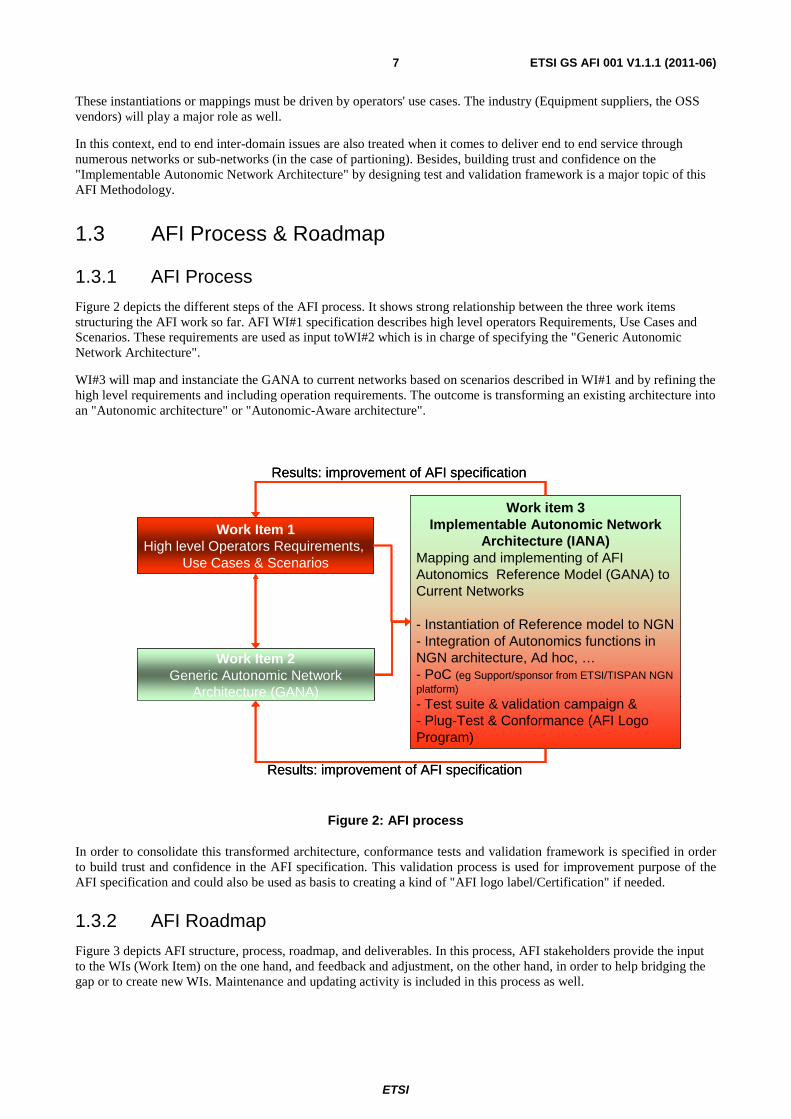
Figure 2 depicts the different steps of the AFI process. It shows strong relationship between the three work items structuring the AFI work so far. AFI WI#1 specification describes high level operators Requirements, Use Cases and Scenarios. These requirements are used as input toWI#2 which is in charge of specifying the "Generic Autonomic Network Architecture".
WI#3 will map and instanciate the GANA to current networks based on scenarios described in WI#1 and by refining the high level requirements and including operation requirements. The outcome is transforming an existing architecture into an "Autonomic architecture" or "Autonomic-Aware architecture".
Figure 2: AFI process
In order to consolidate this transformed architecture, conformance tests and validation framework is specified in order to build trust and confidence in the AFI specification. This validation process is used for improvement purpose of the AFI specification and could also be used as basis to creating a kind of "AFI logo label/Certification" if needed.
1.3.2 AFI Roadmap
Figure 3 depicts AFI structure, process, roadmap, and deliverables. In this process, AFI stakeholders provide the input to the WIs (Work Item) on the one hand, and feedback and adjustment, on the other hand, in order to help bridging the gap or to create new WIs. Maintenance and updating activity is included in this process as well.
Work Item 1High level Operators Requirements,
Use Cases & Scenarios
Work Item 2Generic Autonomic Network
Architecture (GANA)
Work item 3Implementable Autonomic Network
Architecture (IANA)Mapping and implementing of AFI Autonomics Reference Model (GANA) to Current Networks
- Instantiation of Reference model to NGN - Integration of Autonomics functions in NGN architecture, Ad hoc, …- PoC (eg Support/sponsor from ETSI/TISPAN NGN platform)
- Test suite & validation campaign & - Plug-Test & Conformance (AFI Logo Program)
Results: improvement of AFI specification
Results: improvement of AFI specification

ETSI
ETSI GS AFI 001 V1.1.1 (2011-06) 8
Figure 3: Depicts AFI structure, process, methodology, roadmap, and deliverables
2 References References are either specific (identified by date of publication and/or edition number or version number) or non-specific. For specific references, only the cited version applies. For non-specific references, the latest version of the reference document (including any amendments) applies.
Referenced documents which are not found to be publicly available in the expected location might be found at http://docbox.etsi.org/Reference.
NOTE: While any hyperlinks included in this clause were valid at the time of publication ETSI cannot guarantee their long term validity.
2.1 Normative references Not applicable.
2.2 Informative references The following referenced documents are not necessary for the application of the present document but they assist the user with regard to a particular subject area.
[i.1] P. Horn. Autonomic Computing: "IBM's perspective on the State of Information Technology" http://www.research.ibm.com/autonomic/, Oct 2001, IBM Corp.
[i.2] IBM: "An architectural blueprint for autonomic computing". Technical report, IBM White paper (June 2005).
[i.3] J.L. Crowley, D. Hall, R. Emonet: "Autonomic computer vision systems" in J. Blanc-Talon (Ed.), IE EE Advanced Concepts for Intelligent Vision Systems ICIVS 2007.
[i.4] ITU-T Recommendation M.3060/Y.2401 (03/2006): "Principles for the Management of Next Generation Networks".
[i.5] ETSI TS 188 001 (V1.1.1): "Telecommunications and Internet Converged Services and Protocols for Advanced Networking (TISPAN); NGN management; Operations Support Systems Architecture".
[i.6] TeleManagement Forum TR133-REQ V1.2: "NGN Management Strategy: Policy Paper".
AFI
DeliverablesAFI and its
stakeholders
WI 1 Requirements
Use Cases
Scenarios
WI 2Translation into
WI 3
Feedback/Adjustment
AFI
DeliverablesAFI and its
stakeholders
WI 1 (2009)
Requirements
Use Cases
Scenarios
WI 2(2010)
Translation into (2011)
Update- Maintenance
Feedback/Adjustment
IANAGANA
AFI
DeliverablesAFI and its
stakeholders
WI 1 Requirements
Use Cases
Scenarios
WI 2Translation into
WI 3
Feedback/Adjustment
AFI
DeliverablesAFI and its
stakeholders
WI 1 (2009)
Requirements
Use Cases
Scenarios
WI 2(2010)
Translation into (2011)
Update- Maintenance
Feedback/Adjustment
IANAGANA
ETSI
ETSI GS AFI 001 V1.1.1 (2011-06) 9
[i.7] "White Paper MUSE Business Model in BB Access" Multi Service Access Everywhere FP6 project http://www.ist-muse.org/Deliverables/WhitePapers/White-Paper-Business-roles.pdf.
[i.8] EC funded FP7 EFIPSANS Project: Exposing the Features in IP version Six protocols http://www.efipsans.org/.
[i.9] EC funded FP7 CARMEN Project: "CARrier grade MEsh Networks" http://www.ict-carmen.eu/.
[i.10] A Requirement Specification by the NGMN Alliance NGMN Recommendation on SON and O&M Requirements, NGMN alliance, (2008) http://www.ngmn.org/uploads/media/NGMN-Recommendation-on-SON-and-O-M-Requirements.pdf.
[i.11] EC Funded Autonomic Computing and Networking: "The operators' vision on technologies, opportunities, risks and adoption roadmap" P1855 Eurescom.
[i.12] Next Generation Mobile Networks Use Cases related to Self Organising Network, Overall Description, NGMN alliance, 2007.
[i.13] Autonomic Communication, White Paper, Fraunhofer FOKUS November 2004.
[i.14] IEEE 802.11: "IEEE Standard for Information technology - Telecommunications and information exchange between systems - Local and metropolitan area networks - Specific requirements - Part 11: Wireless LAN Medium Access Control (MAC) and Physical Layer (PHY) Specifications".
[i.15] ETSI GS AFI 002: "Autonomic network engineering for the self-managing Future Internet (AFI); Generic Autonomic Network Architecture".
3 Definitions and abbreviations
3.1 Definitions For the purposes of the present document, the following terms and definitions apply:
Autonomic Behaviour (AB): It is linked to understanding how desired element's behaviours are learned, influenced or changed, and how, in turn, these affect other elements, groups and network [i.13].
autonomic manager element: functional entity that drives a control-loop meant to configure and adapt (i.e. regulate) the behaviour of a managed resource e.g. a protocol module or some other type of a managed entity such as a component, by processing sensory information from the managed resource and from other types of required information sources and reacting to observed conditions by effecting a change in the behaviour of the managed resource to achieve some goal
autonomic networking: "new networking paradigm" that involves the design of network devices and the overall network architecture in such a way as to embed "control-loops and feedback mechanisms" that enable the individual devices and the networked systems as a whole, to exhibit the so-called self-managing properties, namely: auto-discovery, self-configuration(auto-configration), self-diagnosing, self-repair (self-healing), self-optimization, etc.
NOTE: The term autonomic comes from the autonomic nervous system, which controls many organs and muscles in the human body. Usually, we are unaware of its workings because it functions in an involuntary, reflexive manner - for example, we do not notice when our heart beats faster or our blood vessels change size in response to temperature, posture, food intake, stressful experiences and other changes to which we are exposed. And our autonomic nervous system is always working [i.2] Alan Ganek, VP Autonomic Computing, IBM.
context awareness: property of an autonomic application/system that enables it to be aware of its execution environment and be able to react to changes in the environment [i.1]
ETSI
ETSI GS AFI 001 V1.1.1 (2011-06) 10
Decision Element (DE): ETSI GS AFI 002 [i.15] produced by WI#2 defines in more detail so-called Decision-Making-Elements (DMEs) referred in short as Decision Elements (DEs) that fulfil the role of Autonomic Manager Elements, each of which is designed and assigned to autonomically manage and control some Managed Entities (MEs) assigned to be managed and controlled by a concrete DE. An ME is a protocol or a mechanism implemented by some functional entity. A Decision Element (DE) in an "Autonomic Manager Element" implements the logic that drives a control-loop over the "management interfaces" of its assigned Managed Entities (MEs). Therefore, in AFI, self-* functionalities are functionalities implemented by Decision Element(s).
GANA (Generic Autonomic Network Architecture): Conceptual Architectural Reference Model for Autonomic Network Engineering, Cognition and Self-Management, whose purpose is to serve as a "blueprint model" that prescribes design and operational principles of "autonomic decision-making manager elements" responsible for "autonomic" and "cognitive" management and control of resources (e.g. individual protocols, stacks and mechanisms)
NOTE: It is not an implementation architecture per se. Refer to ETSI GS AFI 002 [i.15] produced by WI#2 for more details.
Managed Entity (ME): protocol or mechanism implemented by some functional entity that does a specific job for which it is designed to perform and can be managed by an Autonomic Manager Element (i.e. a Decision Element) in terms its orchestration, configuration and re-configuration through parameter settings
overlay: logical network that runs on top of another network
EXAMPLE: Peer-to-peer networks are overlay networks on the Internet. They use their own addressing system for determining how files are distributed and accessed, which provides a layer on top of the Internet's IP addressing.
self-advertise: An autonomic entity should be able to advertise its self-model, capability description model, or some information signalling message (such as IPv6 routing advertisement) to the network in order to allow communication with it or to allow other entities to know whatever is being advertised.
self awareness: autonomic application/system which "knows itself" and is aware of its state and its behaviors [i.1]
NOTE: Knowledge about "self" is described by a "self-model".
self configuration: autonomic application/system should be able to configure and reconfigure itself under varying and unpredictable conditions [i.1]
self-descriptive: ability of a component or system to provide a description of its self-model, capabilities and internal state [i.3]
self healing: autonomic application/system should be able to detect and recover from potential problems and continue to function smoothly [i.1]
self-monitoring: ability of a component or system to observe its internal state, for example, including such quality-of-service metrics as reliability, precision, rapidity, or throughput [i.3]
self optimisation: autonomic application/system should be able to detect suboptimal behaviors and optimize itself to improve its execution [i.1]
self organizing: self-organising function in network includes processes which require minimum manual intervention [i.12]
self partioning: introducing level of automation within the partioning process
self protecting: autonomic application/system should be capable of detecting and protecting its resources from both internal and external attack and maintaining overall system security and integrity [i.1]
self-regulation: ability of a component or system to regulate its internal parameters so as to assure a quality-of-service metric such as reliability, precision, rapidity, or throughput [i.3]

ETSI
ETSI GS AFI 001 V1.1.1 (2011-06) 11
3.2 Abbreviations For the purposes of the present document, the following abbreviations apply:
AB Autonomic Behaviour ABGet Available Bandwidth Get AC ME Admission Control Managed Entity AF Autonomic Function AFI Autonomic network engineering for the self-managing Future Internet AP Access Point API Application Protocol Interface App_DE Application Decision Element BS Base Station BSS Business Support System CLI Command-Line Interface DE Decision Element DHT Distributed Hash Tables DME Decision Making Element E2E End to End EMS Element Management System EPC Evolved Packet Core GANA Generic Autonomic Network Architecture HAN Home Area Network IaaS Infrastructure as a Service IANA Implementable Autonomic Network Architecture IDS Intrusion Detection Systems IMS IP Multimedia SubSystem IPv4/IPv6 Internet Protocol version 4 or 6 ISP Internet Service Provider KPI Knowledge Plane Information LTE Long Term Evolution MANET Mobile Ad-hoc NETworks ME Managed Entity NE Network Element NGN Next Generation Network NGOSS New Generation Operations System and Software NMS Network Management System NO Network Operator OAM Operating and Maintenance OPEX OPeration EXpediture OSS Operation Support System OTT Over The Top OVN Overlay Virtual Network P2P Peer to Peer QoE Quality of Experience QoS Quality of Services QoS_DE Quality of Service Decision Element Saas Service as a service SLA Service Level Agreement SMS Short Message Service SOHO Small Office Home Office SON Self Organising Network TSPEC Traffic Specification VNO Virtual Network Operator WI Work Item

ETSI
ETSI GS AFI 001 V1.1.1 (2011-06) 12
4 AFI's Requirements for an Autonomic Network Figure 4 depicts the global diagram describing the process and tools used by AFI Work Item 1 for designing "AFI requirements".
The starting point is capturing autonomic issues and global context from top level in order to shape the current and Future network vision. This serves as input to formulate operators' requirements from operation view point. The result is shaping AFI high level requirements thanks to a dedicated template as tool.
From the bottom level, this AFI requirement template is refined by inputs coming from AFI Use Cases & Scenarios structured within appropriate template as tool.
Figure 4: AFI process and tools for designing requirements & scenarios
4.1 Current NGN network Next Generation Network (NGN) is a network architecture that almost all operators are deploying. Within NGN, the core network is based on IP and multiple access technologies and devices that may coexist alongside this IP core network. IP connectivity among users is a must. IP Multimedia subsystem (IMS) is the first distributed control service architecture for fixed/wired and mobile access network. It is deployed to facilitate service convergence.
NGN is the current network architecture for operators to fulfil the requirements that arise from new market realities:
• Open competition (especially in terms of new services deployment, to provide the best QoS, to reduce prices/costs/OPEX)
• Deregulation of markets (e.g. separation between network and service planes)
• Explosion of digital traffic
• Convergence (fixed/mobile)
• Mobility (inside converged networks, between several networks (Web services))
AFI captured autonomics Issues and global context
Current NGN network Future network vision
Operator's & other Requirements
AFI requirements(AFI requirement template)
AFI Use Case & Scenarios(AFI template Use Case & Scenarios)
4.1 4.2
4.2 4.3 4.4
4.6
AFI Use Case & Scenarios(AFI template Use Case & Scenarios)AFI Use Case & Scenarios
(AFI template Use Case & Scenarios)
AFI requirements(AFI requirement template) AFI requirements
(AFI requirement template) AFI Requirements(AFI requirement template)
AFI Use Case & Scenarios(AFI Use Case & Scenarios template)
5

ETSI
ETSI GS AFI 001 V1.1.1 (2011-06) 13
Next Generation Network (NGN) is defined by ITU-T as a layered network and services architecture using a packet-based transport network and a unified control layer that is able to provide telecommunication services with QoS over different broadband access networks [i.4]. NGN supports generalized mobility/nomadic functions allowing consistent and ubiquitous access to services.
Figure 5: NGN Architecture overview
Network and service decoupling is one of the main NGN concepts. Such decoupling is reflected in the NGN architecture. As it can be viewed in figure 5, there is a clear separation between Service and Transport layers. NGN covers different access networks through a common IP core. For NGN, it is necessary to have IP connectivity among users.
4.2 Future network vision In the future, processing, storage and communication services will be highly pervasive, intertwined and strongly related to each other. What we expect is that people, smart objects, machines and the surrounding space will all be embedded with devices such as sensors, RFID tags, etc., defining highly decentralized dynamic network environments of virtual resources interconnected by wired and wireless connectivity. Overlay networks will be the major means to organize and aggregate these highly dynamic communication environments.
Virtualization of resources (from networking to processing to storage, etc) will be a key characteristic of future networks. As a consequence, autonomic features should support functions such as the creation and maintenance of overlay networks of virtual resources (for instance autonomic features might be integrated with hypervisors'/VMM's capabilities).
Networks will evolve towards a broader perspective to include not only connectivity resources but also other types of resources such as processing, storage and things (e.g. terminals, sensors, actuators, etc.). This is a more holistic and future proof vision of the network environment (useful for analysing various scenarios/use-cases: from zero-configuration Home to Cloud Computing, to Content Delivery Networks, etc.).
4.3 Operator's requirements The scope in this clause is mainly focused on end to end services management from user perspective within an evolved network. Besides, some operators have to deal with the legacy network that is why we need to seek how to adapt TISPAN, 3GPP, IMS architectures in order to make the introduction of autonomic functions easier and smoother in physical, virtualized, distributed centralized resources. Therefore, in addition to user's requirements, a set of technical and management requirements for operators to deal with an autonomic network have also been captured.
DEVICES ACCCESS
TRANSPORT CONTROL
SERVICES
Core Network
WLAN
UMTS
GPRS
FIXED
Internet
DEVICES ACCCESS
TRANSPORT CONTROL
SERVICES
Core Network
WLAN
UMTS
GPRS
FIXED
Internet
ETSI
ETSI GS AFI 001 V1.1.1 (2011-06) 14
The first step is to introduce a "knowledge plane" in the network taking into account the legacy network on the one hand, and services (IMS), access (TISPAN, 3GPP,) and home access networks (Broadband Forum reference architecture, "Authone: Autonomic Home Networking" project, for instance), on the other hand. This knowledge plane must take into account the constraints of all the actors and security concerns. Data in the knowledge plane must be up to date and granted. Information from different actors could be shared by context defined by an ontology.
Autonomic features would decide locally based on knowledge retrieved from analysed information of the global network. Based on such knowledge, local decisions would be taken in respect of end to end or global views, e.g. configuration of network elements from end to end constraints actors view point, mobility control between different heterogeneous access network (WiFi, Wimax, 2G/3G/LTE), services adapted to user context.
The following set of requirements defines a set of operational requirements for an operator to control an Autonomic and Self-Managing Future Network. The requirements have implications on the operational principles of autonomic components of an autonomic network e.g. federation requirements, information sharing, and other types of desired behaviours in networks (as described later with figure 7) which illustrate a Policy Management framework.
In this context two views need to be highlighted: "cross layers autonomic views" within an operator's network in one hand, and "cross domain autonomic view" through various domains in this other hand. (By domain, we mean here "players" as described later with figure 6).
Indeed, from "cross layers autonomic views", an upper layer "cognition function" is able to retrieve from local views a situated view of its environment. At a lower layer which embeds an Autonomic Function it becomes possible to retrieve objectives from upper layers in order to make a decision locally with a global objective, to different layers (as described later with figure 8).
Regarding "cross domain autonomic view", the cognition functions are used here with the goal to disseminate the knowledge through various domains (as described later with figure 9). Indeed, each "Autonomic Function" will use this "cognition function" to react locally with a common objective, to different domains. This horizontal autonomics architecture is required in order to manage end to end services autonomously if needed (players' agreements, regulation constraints, etc.).
4.4 Management requirements This clause gathers the set of operational and management requirements for an operator to deal with an autonomic network. Starting from users' requirements, a set of operational and maintenance requirements are captured for an operator to fulfil the quality expectations of users. This work is aligned with the NGN management requirements that can be found in [i.6] and [i.5] where a first level of requirements (level 0) is composed by:
• Customer centric requirements
• Business vision requirements
• Technology requirements
• Operational requirements
• Regulatory requirements
These requirements were studied in order to understand what is needed for the operation of NGN infrastructures and how an autonomic network can help to simplify such operation. In fact only the Technology and Operational requirements are covered here.
The first set of requirements in table 2 is user oriented. Users want to have access to adapted services that they choose with a guarantee of security & quality. This implies requirements from operators' perspective: OAM requirements.
4.4.1 Network management driven by players
In order to translate end user requirements into technical requirements within the operators' networks, the following template is used as a guideline. It contains the following fields:
• Players
• Network environment
ETSI
ETSI GS AFI 001 V1.1.1 (2011-06) 15
• Scenario
• What is the requirement
• What need to be automated (this field is more linked to WI 2. It is here only to better understand the technical requirement)
In order to better capture operators' requirements and map them to the relevant scenarios, the methodology used here is the partioning of the network of operator we named "Network Environment".
Following is an instantiation of this Network environment concept:
• home area network (SOHO network)
• access network
• regional network
• service platform
• content platform
• ad hoc
• IT platform
• User Network
• Other, etc.
Some of the definitions related to the "player" in the present document are derived from the "Muse" project.
Following is an instantiation of this "Player" concept:
• User Network
• User Service
• Subscriber [i.7]
• Application service provider [i.7]
• Multimedia content provider [i.7]
• Multimedia service provider
• Network connectivity provider [i.7]
• Access network provider [i.7]
• Regional network provider [i.7]
• Network service provider [i.7]
• Internet service provider [i.7]
• Packager [i.7] (operators with different players or make the link with different players (VNO))
• Third party
• Identity provider
• Government (regulator)
• Application developer
• OTT: Over The Top (e.g. Google, Apple, Microsoft, etc.)
ETSI
ETSI GS AFI 001 V1.1.1 (2011-06) 16
• Network outsource actor
• Service outsource actor
• User content provider
• Community service provider
• Network community stakeholder
• Social network stakeholder, etc.
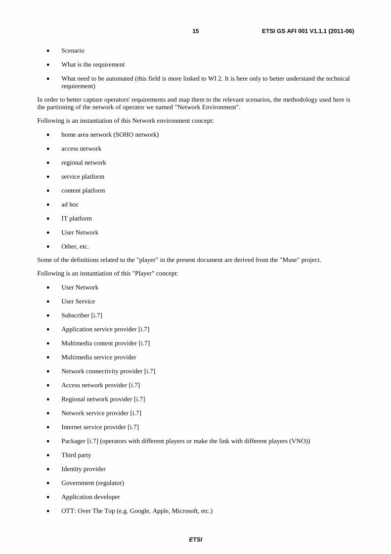
Figure 6 shows player dependencies from a network environment point of view. Network environment management is driven by the different players of the network. There is no longer one operator that owns the whole network, but a web of players that offer service and network interfaces to others [i.7]. Autonomic technologies must guarantee that a player to control their own environment and at the same time assure the end to end view, which emerges from the individual behaviors of all the players.
Figure 6: Network environment management driven by players
4.4.2 Requirement framework for a Policy- based management
This framework illustrates the evolution of the network management in order to become intelligent, open, flexible, Autonomous, secure, Context-Aware, Policy-based, Business-driven and SLA-driven. It is structured through the 4 following requirements from an operator perspective. In order to better understand the description of this requirement, alongside describing these requirements themselves, we mapped them with regards to a high level operator's network.
Strategic requirements
This requirement is focusing on business intelligence and associated partnerships necessary to implement this strategy.
• Minimize OPEX/CAPEX
• Maximize user satisfaction
… Service Provider
User Network
Fixed accessNetwork (TISPAN)
AS Network
Hotspot
Mobile AccessNetwork (3GPP)
IMS
CoreNetwork
Ad Hoc
Home AreaNetwork
ApplicationServer
Multimedia Service ProviderTelephony Service
ProviderApplication ServiceProviderVirtual Service (Xaas,
Cloud)ProviderInternet ServiceProviderNetwork ServiceProviderTriple play Service
ProviderMultimedias Content
Provider
Third Partyprovider
… Network provider
Hotspot access NetworkproviderMobile access NetworkproviderFixed access Network
providerVirtual NetworkproviderEnterprise Network
providerWholesaler accessproviderOperation outsousrcing
Provider
Players
Network Environment
…
User Network
Network outsourcing
WLAN
UTRANEDGE
FTTH
XDSL
POTSLAN
Connectivity Provider
Network community stakeholderUser content providerService
outsourcing
User Service
Social Network stakeholderCommunity Service
ProviderOn the Top

ETSI
ETSI GS AFI 001 V1.1.1 (2011-06) 17
• Minimize carbon footprint
• Maximize revenues
In this context, we illustrated this partnership from stakeholders and partners' viewpoint by a high level (abstraction) layered architecture composed of two main domains, Operator's domain and Vendors' domain.
At the top level, we depicted the operator's domain which includes 3 layers: Business Policy, Service objective, Operator's OSS. At the bottom level, we can see vendors' domain which includes the network and its associated Management System.
Governance requirements
For the purpose of this network governance, an interface is needed to allow the operator to adjust the features of the demanded service/infrastructure. The reason why, a business level language is required to help the operator to express what it is needed from the network. Such business language must be semantics-oriented and may be modelled by the use of ontology to add semantics and enable machine reasoning on the goals.
Indeed, the operators and services providers are expecting benefits & usability of ontologies in their service strategies within highly competitive and fast moving Internet market environment with strong Time-To-Market constraints. Ontologies capture the semantics of information from various sources is a powerful tool in services design, service composition (service logic) and service personalization through specific user profiles in a dynamic way. At the same time, current oriented-object information models specified by various SDOs (SID from TMF and CIM from DMTF or IRP from 3GPP F, etc.) are less flexible to meet this objective. This requirement has a direct impact on existing BSS/OSS information models. The immediate integration path of the legacy can be achieved by encapsulating.
Such a Business Policy level description eases the automation of "Edition - Translation - Execution" of Policies. This leads to the translation into "Service Profiles" at Service level and into "Network Profiles" at Network level.
Finally, after translation phase the distribution process of Service Profiles & Network Profiles is performed in order to prepare the execution and enforcement. The last phase of this process is the "Policy & Rule Enforcement & Execution" by the Network part (NEs) in the vendor's domain as depicted in figure 7.
This approach for network governance gives the operator a mechanism for controlling the network.
Operational requirements
This requirement aims at improving operation efficiency (reduce OPEX). One way to achieve this goal is to harmonize BSS/OSS, Data Models and deploy of a standardized northbound management interface. Such a harmonization is vital in the context of fixed-Mobile network & services management.
From management architecture perspective, figure 7 maps these "Operational requirements" to the real operator architecture which will handle the implementation. The network environment (Vendors' domain in the figure) will be managed by business objective which will drive the service objective. The service objective will be then translated into policy rules which will be enforced in the operator's network through the operator's Network Management System (NMS). The policy enforcement will be then executed by the different vendor's Element Management System (EMS) and the Network Elements (NE) forming the operator's network. Each layer of the whole architecture will take into account its intrinsic constraints.
Autonomous & Cognition requirements
This requirement aims at taken advantage from introducing Self-Awareness, Learning, and Reasoning capabilities and mechanisms. It also includes gathering information, transforming it into knowledge & distributing it to various needs. There is also a need to building and ensuring Trust & Confidence as well as Stability in Autonomics loops and in the network.
From management architecture perspective, figure 7 maps these "Autonomous & Cognition requirements" to the real management architecture.
The cognition aspect is shown by "cognition module" (purple boxes) in the right part of the figure. These cognition modules are used to retrieve relevant knowledge from data/information and it allows the cross-control loop interactions accordingly. These cognition modules can also be seen as "brokers" where various knowledge sources store the knowledge in a controlled and secured way, while, the users of these knowledge retrieve required and relevant knowledge through a subscription model. In this context, a dissemination plane is used to disseminate knowledge and decision.
ETSI
ETSI GS AFI 001 V1.1.1 (2011-06) 18
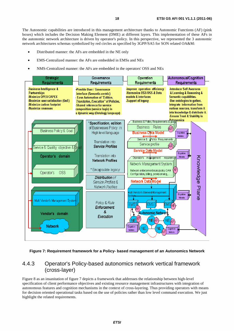
The Autonomic capabilities are introduced in this management architecture thanks to Autonomic Functions (AF) (pink boxes) which includes the Decision Making Element (DME) at different layers. This implementation of these AFs in the autonomic network architecture is driven by operator's policy. In this perspective, we represented the 3 autonomic network architectures schemas symbolized by red circles as specified by 3GPP/SA5 for SON related OA&M:
• Distributed manner: the AFs are embedded in the NE only
• EMS-Centralized manner: the AFs are embedded in EMSs and NEs
• NMS-Centralized manner: the AFs are embedded in the operators' OSS and NEs
Figure 7: Requirement framework for a Policy- based management of an Autonomics Network
4.4.3 Operator's Policy-based autonomics network vertical framework (cross-layer)
Figure 8 as an insanitation of figure 7 depicts a framework that addresses the relationship between high-level specification of client performance objectives and existing resource management infrastructures with integration of autonomous features and cognition mechanisms in the context of cross-layering. Thus providing operators with means for decision oriented operational tasks based on the use of policies rather than low level command execution. We just highlight the related requirements.

ETSI
ETSI GS AFI 001 V1.1.1 (2011-06) 19
Strategic requirements
• Business Intelligence & Partnerships with E2E view
• Minimize OPEX/CAPEX
• Maximize user satisfaction (QoE)
• Minimize carbon footprint
• Maximize revenues
Governance requirements
• Cross-layer User / Governance interface (Semantic-centric)
• Ease Automation of "Edition, Translation, Execution" of Policies
• Shared reference for service composition (service logic) in a dynamic way (Ontology language)
Operation requirements
• Improve operation efficiency
• Harmonize BSS/OSS & Data models & interfaces in cross-layer model
• Support of legacy
Autonomous & Cognition requirements
• Introduce Self Awareness & Learning & Reasoning & Semantic capabilities
• Use ontologies to gather, integrate information from various sources, transform it into knowledge & distribute it in cross-domain model
• Ensure Trust & Stability in Autonomics

ETSI
ETSI GS AFI 001 V1.1.1 (2011-06) 20
Figure 8: Operator's Policy-based autonomics network vertical framework
From cognition perspective, an upper layer "cognition module" (purple boxes) is able to retrieve from local views a situated view of its environment. From autonomous point of view, these layers are connected through the red loops. Indeed, an Autonomous Function (AF) (pink boxes) located in bottom layer can retrieve objectives from upper layers in order to make a decision locally with a global objective.
The cognition interaction is required in order to gather and disseminate the knowledge produced at a knowledge/ dissemination plane through "cognition function" for the red loop process purpose and it allows the cross-control loop interactions accordingly.

ETSI
ETSI GS AFI 001 V1.1.1 (2011-06) 21
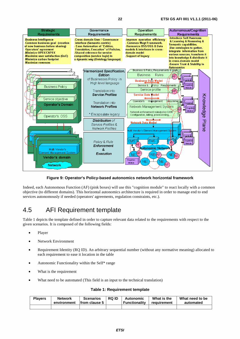
4.4.4 Operator's Policy-based autonomics network horizontal framework (cross-domain)
The aim of Operator's Policy-based autonomics network horizontal framework is to describe the cross-domain interaction from autonomics and cognition perspective. It is also an instantiation of figure 7. We just highlight the related requirements.
Strategic requirements
• Business Intelligence
• Common business goal (creation of new business before sharing) Operators' agreement
• Minimize OPEX/CAPEX
• Maximize user satisfaction (QoE)
• Minimize carbon footprint
• Maximize revenues
Governance requirements
• Cross-domain User / Governance interface (Semantic-centric)
• Ease Automation of "Edition, Translation, Execution" of Policies
• Shared reference for service composition (service logic) in a dynamic way (Ontological language)
Operation requirements
• Improve operation efficiencY
• Common Management Framework
• Harmonize BSS/OSS & Data models & interfaces in cross-domain model
• Support of legacy
Autonomous & Cognition requirements
• Introduce Self-Awareness & Learning & Reasoning & Semantic capabilities
• Use ontology to gather, integrate information from various sources, transform it into knowledge & distribute it in cross-domain model
• Ensure Trust & Stability in Autonomics
The cognition modules (purple boxes) are used here with the goal to disseminate the knowledge through various domains. By domain, we mean here an operator network or an administrative view of a global operator network (Access or Backhaul or Core). It corresponds to a partitioning of a global network. These cognition modules as "brokers" where various knowledge from various operators store their knowledge in a controlled and secured way, while, the users (belonging to various players) of these knowledge retrieve required and relevant knowledge they need through a subscription model This approach gives the operators a mechanism for controlling the knowledge they provide in this cross-domain autonomic management.
ETSI
ETSI GS AFI 001 V1.1.1 (2011-06) 22
Figure 9: Operator's Policy-based autonomics network horizontal framework
Indeed, each Autonomous Function (AF) (pink boxes) will use this "cognition module" to react locally with a common objective (to different domains). This horizontal autonomics architecture is required in order to manage end to end services autonomously if needed (operators' agreements, regulation constraints, etc.).
4.5 AFI Requirement template Table 1 depicts the template defined in order to capture relevant data related to the requirements with respect to the given scenarios. It is composed of the following fields:
• Player
• Network Environment
• Requirement Identity (RQ ID). An arbitrary sequential number (without any normative meaning) allocated to each requirement to ease it location in the table
• Autonomic Functionality within the Self* range
• What is the requirement
• What need to be automated (This field is an input to the technical translation)
Table 1: Requirement template
Players Network environment
Scenarios from clause 5
RQ ID Autonomic Functionality
What is the requirement
What need to be automated

ETSI
ETSI GS AFI 001 V1.1.1 (2011-06) 23
4.6 AFI high level Requirements Categorization of the requirements
Based on the master template of the table 1, tables 2 to 7 are the instantiations of this template to relevant scenarios identified in the present document. This list will be enriched and extended with new set of scenarios and use cases in the next release.
This classification is Players-oriented:
• User player requirement (table 2)
• Manufacturer requirement (table 3)
• Access Network requirement (table 4)
• Access and Core Network players requirements (table 5)
• Services players requirements (table 6)
• Access network / core network / Services players requirements (table 7)
• Content player requirement (table 8)
• Cross-players requirements (table 9)
Each of the following tables below contains set of requirements organized primarily by the player involved in the requirement. Furthermore, from a management point of view, the requirements can be classified by the autonomic functionality needed. Namely:
• Self-configuration
• Self-optimization
• Self-monitoring
• Self-diagnose
• Self-healing
• Self-protection
• Self-management

ETSI
ETSI GS AFI 001 V1.1.1 (2011-06) 24
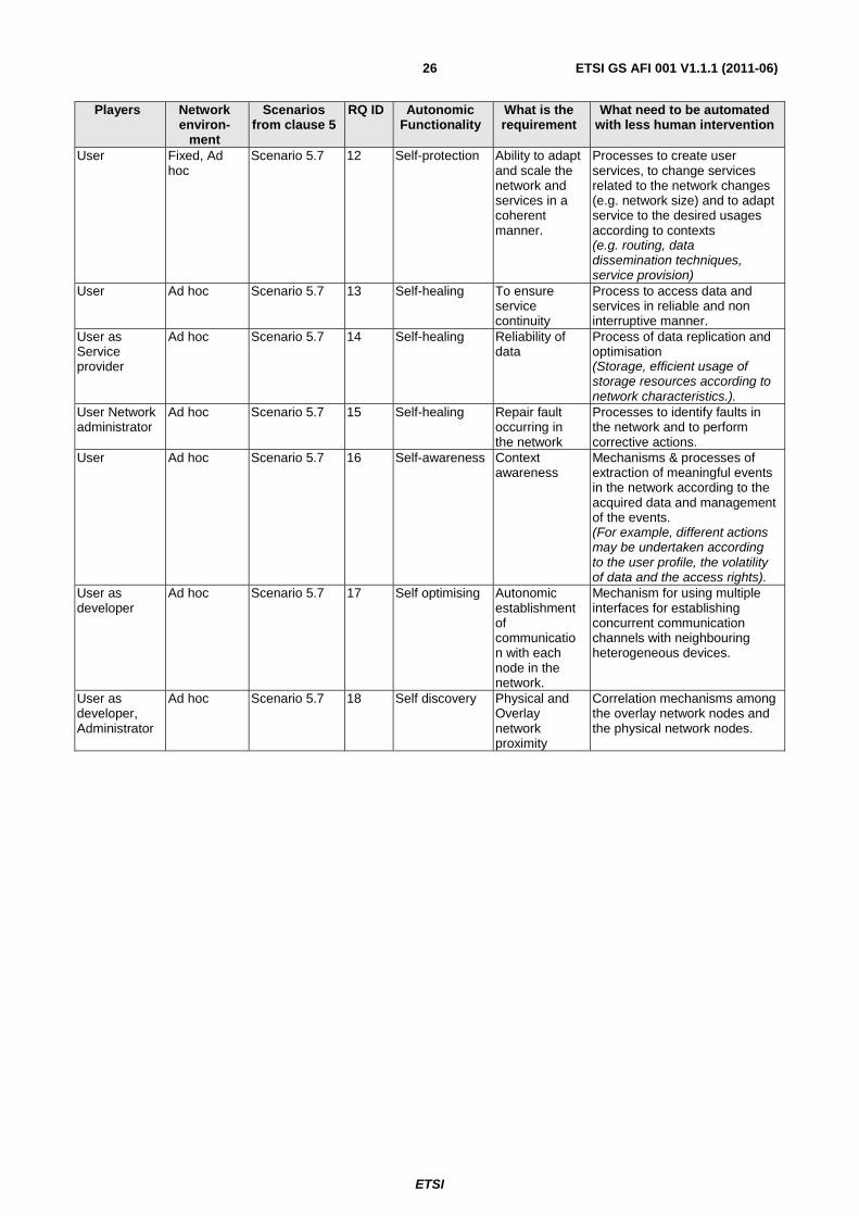
Table 2: User player requirement
Players Network environ-
ment
Scenarios from clause 5
RQ ID Autonomic Functionality
What is the requirement
What need to be automated with less human intervention
User Ad hoc Scenario 5.7 1 Self-organising User equipment must be able to attach itself to the ad-hoc network and participate in self organizing of the network in a given context
Network organising process through network element (Each network node may be able to connect to the ad-hoc network and establish communication with neighbouring nodes as well as other network nodes without the need for any centralized element.)
User as network operator and developer
Ad hoc Scenarios 5.4, 5.7
2 Auto-Discovery and Self configuration
Autonomic establishment of communication with each node in the network.
Network discovery process through network element (A node joins the network and is able to recognize its neighbours and communicate with them. Through the application of a proper routing protocol, it is also able to communicate with any other node. Multi-hop communication must be established autonomically).
User Ad hoc Scenario 5.7 3 Self-configuration
Zero configuration in order to connect to the existing infrastructure
Network configuration process through network element (The node, upon identification of its neighbours, is able to join the network and self-configure itself and connect to the "gateway". There is no need for existence of a centralized or predefined entity in order to provide specific configuration files or guidelines to each new participant node).
User Ad hoc Scenario 5.7 4 Self-awareness Ability to gather knowledge in order to be available
Process of gathering knowledge form the network (The overlay network plays the role of a distributed repository for all network nodes. According to the stored information, virtual communities may be created in the overlay network by sharing specific data on it and permitting access to part of its members).
User Home area network
Scenario 5.2 5 Self-Configuration
The user must be able to configure, add equipment and services, control and optimise the home network
Home Area network configuration Process under the control of the human (Zero configuration: Home Area Network configuration should take into account user context (user equipment, profile subscription, preferences, user services, etc.) regardless of the access network)

ETSI
ETSI GS AFI 001 V1.1.1 (2011-06) 25
Players Network environ-
ment
Scenarios from clause 5
RQ ID Autonomic Functionality
What is the requirement
What need to be automated with less human intervention
User as network, developer
Ad hoc Scenario 5.7 6 Self-configuration
Autonomic bootstrapping of devices in the network and Autonomic bootstrapping of networks as well
Bootstrapping process of network element and the network (The network must be established automatically without the need of any existing infrastructure).
User as network, , developer
Ad hoc Scenario 5.7 7 Self-configuration
To build a registration knowledge plane without human intervention (Decentralized registration for special data. Specific nodes in the network can be selected as registration entities. Registration related roles can be allocated dynamically according to predefined criteria).
Process to build a knowledge plane (The network must be established automatically with knowledge without the need of any existing infrastructure).
User as network administrator
Ad hoc Scenario 5.7 8 Self-configuration
Retrieve, analyse, process (reason, learn) data and transforming it into knowledge to be used by authorised requesters
Process to organise knowledge.
User All Scenario 5.2 9 Self-provisioning
Provision services with users context
Process to provision services according to the information authorised by users.
User Ad hoc Scenario 5.2 10 Self-protection Player (e.g. user enterprise, residential user, etc.) could provide, add and create services
-Mechanisms to Select the needed functionality to provide advanced and secure services on user requirement basis. -Process to propose/publish services to authorised users. -Process to build services. (to create, publish, access, control, bill, QoS manage the services provided by the players (e.g. user))
User all Scenario 5.7 11 Self discovery Protection of User data.
Process to access user data in secure manner
ETSI
ETSI GS AFI 001 V1.1.1 (2011-06) 26
Players Network environ-
ment
Scenarios from clause 5
RQ ID Autonomic Functionality
What is the requirement
What need to be automated with less human intervention
User Fixed, Ad hoc
Scenario 5.7 12 Self-protection Ability to adapt and scale the network and services in a coherent manner.
Processes to create user services, to change services related to the network changes (e.g. network size) and to adapt service to the desired usages according to contexts (e.g. routing, data dissemination techniques, service provision)
User Ad hoc Scenario 5.7 13 Self-healing To ensure service continuity
Process to access data and services in reliable and non interruptive manner.
User as Service provider
Ad hoc Scenario 5.7 14 Self-healing Reliability of data
Process of data replication and optimisation (Storage, efficient usage of storage resources according to network characteristics.).
User Network administrator
Ad hoc Scenario 5.7 15 Self-healing Repair fault occurring in the network
Processes to identify faults in the network and to perform corrective actions.
User Ad hoc Scenario 5.7 16 Self-awareness Context awareness
Mechanisms & processes of extraction of meaningful events in the network according to the acquired data and management of the events. (For example, different actions may be undertaken according to the user profile, the volatility of data and the access rights).
User as developer
Ad hoc Scenario 5.7 17 Self optimising Autonomic establishment of communication with each node in the network.
Mechanism for using multiple interfaces for establishing concurrent communication channels with neighbouring heterogeneous devices.
User as developer, Administrator
Ad hoc Scenario 5.7 18 Self discovery Physical and Overlay network proximity
Correlation mechanisms among the overlay network nodes and the physical network nodes.
ETSI
ETSI GS AFI 001 V1.1.1 (2011-06) 27
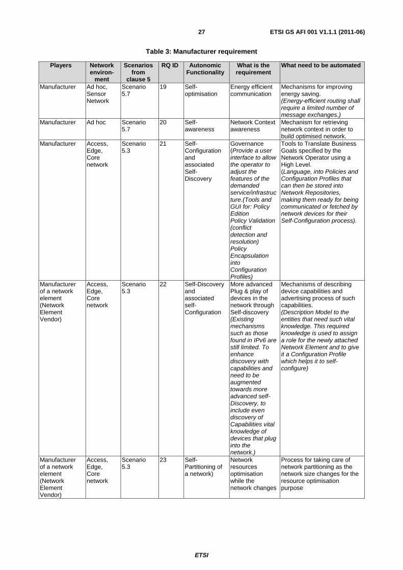
Table 3: Manufacturer requirement
Players Network environ-
ment
Scenarios from
clause 5
RQ ID Autonomic Functionality
What is the requirement
What need to be automated
Manufacturer Ad hoc, Sensor Network
Scenario 5.7
19 Self-optimisation
Energy efficient communication
Mechanisms for improving energy saving. (Energy-efficient routing shall require a limited number of message exchanges.)
Manufacturer Ad hoc Scenario 5.7
20 Self-awareness
Network Context awareness
Mechanism for retrieving network context in order to build optimised network.
Manufacturer Access, Edge, Core network
Scenario 5.3
21 Self-Configuration and associated Self- Discovery
Governance (Provide a user interface to allow the operator to adjust the features of the demanded service/infrastructure.(Tools and GUI for: Policy Edition Policy Validation (conflict detection and resolution) Policy Encapsulation into Configuration Profiles)
Tools to Translate Business Goals specified by the Network Operator using a High Level. (Language, into Policies and Configuration Profiles that can then be stored into Network Repositories, making them ready for being communicated or fetched by network devices for their Self-Configuration process).
Manufacturer of a network element (Network Element Vendor)
Access, Edge, Core network
Scenario 5.3
22 Self-Discovery and associated self-Configuration
More advanced Plug & play of devices in the network through Self-discovery (Existing mechanisms such as those found in IPv6 are still limited. To enhance discovery with capabilities and need to be augmented towards more advanced self-Discovery, to include even discovery of Capabilities vital knowledge of devices that plug into the network.)
Mechanisms of describing device capabilities and advertising process of such capabilities. (Description Model to the entities that need such vital knowledge. This required knowledge is used to assign a role for the newly attached Network Element and to give it a Configuration Profile which helps it to self-configure)
Manufacturer of a network element (Network Element Vendor)
Access, Edge, Core network
Scenario 5.3
23 Self-Partitioning of a network)
Network resources optimisation while the network changes
Process for taking care of network partitioning as the network size changes for the resource optimisation purpose

ETSI
ETSI GS AFI 001 V1.1.1 (2011-06) 28
Table 4: Access Network requirement
Players Network environ-
ment
Scenarios from
clause 5
RQ ID
Autonomic Functionality
What is the requirement
What need to be automated
Access network provider
Home area network
Scenarios 5.2, 5.4
24 Self-configuration
Zero configuration for Home Area Network
-Authentication, attachment, configuration, security processes of devices according to users subscription within a multi-player agreement. (for IP and non IP devices, for services and for users devices (home or nomadic) within the Home Area Network).
Access network provider
HAN, access network
Scenario 5.2 25 Self-configuration
User online subscription
Provisioning and configuration processes of user equipment to implement new services. with notification to the different players with the new subscription.
Access network provider
Home area network
Scenario 5.2 26 Self-diagnose Access network provider must diagnose home network. in order to reduce human intervention
Processes to diagnose HAN and to notify the necessary result to the access network player (-to retrieve data from sensors (statistics event) necessary to fault qualification, based not only on local view alone but also through neighbours. -to Analyze data to identify the fault cause (for already known fault type). -to define the test to identify the fault. - to continuously discover new faults. (i.e. learning method, data analysis in order to identify new fault cause) - to define the test to identify and validate new faults. - to elaborate an end to end diagnosis chain. (identification of neighbours, players or equipment involved in this global diagnose including the agreement between those actors)

ETSI
ETSI GS AFI 001 V1.1.1 (2011-06) 29
Players Network environ-
ment
Scenarios from
clause 5
RQ ID
Autonomic Functionality
What is the requirement
What need to be automated
Access network provider
Home area network/ Access network
Scenarios 5.2, 5.4
27 Self-healing Each failure happening must be repaired in order to guarantee service delivery
Healing process Based on the diagnose report received from the different players. - Notify the player administrator (owner) the method used and the equipment healed - if it is not self-heal notify in case the system could not be repaired remotely - the player, owner (administrator) must be able to validate the method used to repair each fault. -Define methods for protection and restoration - Identification of new path for services. - Protection mechanism in real time.
Access Network provider
Home area network
Scenarios 5.2, 5.4
28 Self-Monitoring Self- Optimisation
The home area network needs to be monitored on a service level and network level
Monitoring process of HAN services (HAN must examine its own traffic load/type parameters (available bandwidth, packet loss, QoS) in order to ensure a reliable and efficient network. - Mechanisms achieving this goal must be done through multi player environment requirements and allow players retrieving monitoring information)
Access network provider
Wireless Mesh Network
Scenario 5.10
29 Self-configuration
Mesh nodes must automatically connect to the network
Mechanisms of recognition of physical network topology (neighbour identification, and utilization of heterogeneous network technologies)
Access network provider
Wireless Mesh Network
Scenario 5.10
30 Self-optimization
to ensure availability of maximum capacity
Process of selecting radio technologies and their configuration according to current radio/traffic conditions (channel, rate selection)
Access network provider
Wireless Mesh Network
Scenario 5.10
31 Self-healing Network must be robust to changes of topology and radio conditions
Monitoring presence of neighbouring nodes and reaction to network events (e.g. link failure)

ETSI
ETSI GS AFI 001 V1.1.1 (2011-06) 30
Table 5: Access and Network players requirements
Players Network environ-
ment
Scenarios from
clause 5
RQ ID
Autonomic Functionality
What is the requirement
What need to be automated
Access and Core Networks provider
Access and Core Networks
Scenario 5.2
32 Self-configuration
Perform network configuration according to user context
Overall network configuration process according to the user context / player context and current local and global context (The overall network configuration including the last mile, regardless of the access technology (wired or wireless), equipment, user and services)
Access and Core Networks provider
Access and Core Networks
Scenarios 5.2, 5.3
33 Self-configuration
Configuration of the network elements in a multiplayers / multiservices context
Management and control process of access, core network and services in a multiplayer, multiservice context
Access and Core networks provider
Access and Core Networks
Scenarios 5.2, 5.4, 5.5
34 Self-monitoring Ensure an efficient node monitoring: with less impact on the performance of the network.
Monitoring process of network fitting the needs requested
Access and Core Networks provider
Access and Core Networks
Scenarios 5.2, 5.4
35 Self-healing Improve fault management
Healing process (Locating the root cause of a fault, which has occurred in the network, correcting this fault and testing the resources of network, regardless of the last mile technology, the services used and the home access. (Detects and repairs IP connectivity). Advertise services and network (end 2 end management))
Access and Core networks provider
Access and Core Networks
Scenarios 5.2, 5.4
36 Self-optimization
Improve Performance
End to end network Node performance process (Network Node must be able to adapt and tune its own performance parameters in order to make proper decisions (self-optimization) with a user, network and services context. Decision must be sent to the player for decision)
Access and Core Networks provider
Access, Core Networks, services (IMS) , content server (Application server)
Scenarios 5.2, 5.4
37 Self-healing Improve Performance
Process of detecting and eliminating congestion. (Define resources element that are under-utilised. Define the functionality needed to be added in the network. Add new functionality in the network with no services disruptions.)
ETSI
ETSI GS AFI 001 V1.1.1 (2011-06) 31
Players Network environ-
ment
Scenarios from
clause 5
RQ ID
Autonomic Functionality
What is the requirement
What need to be automated
Access network and network provider
Access and Core Networks
Scenario 5.2
38 Self-protection Secure network & services
Security mechanisms to protect services and data with appropriate mechanisms from malicious attacks and unauthorized terminals/users. (It can anticipate problems within the network. Functionality distributed in the Home network access and for services layer control)
Network provider
All Scenarios 5.2, 5.3
39 Self -Discovery A new device on the network must be able to Discover its neighbours Inherit routing tables and other information (as today) Inherit Policies Learn its context and enhance Initialise its configuration settings
Discovery mechanisms
Network provider
All Scenario 5.2
40 Self-adaptation Backward compatibility (An autonomic network must be able to perform all of the functionality currently available in today's networks)
Integration process of legacy network & services
Network provider
All Scenario 5.2
41 Self-provisioning
-Authorised user(s) must be able to create/edit/activate/deactivate business policies. -Activated business policies must be communicated to all relevant network devices. -All network devices should adapt their configurations and operations to meet these business policies as best they can.
User interface towards Business Policy Manager

ETSI
ETSI GS AFI 001 V1.1.1 (2011-06) 32
Players Network environ-
ment
Scenarios from
clause 5
RQ ID
Autonomic Functionality
What is the requirement
What need to be automated
Network operator
All Scenario 5.2
42 Self-configuration
Authorised user(s) must be able to override the configuration of a device that has been autonomically set.
User interface towards configuration process
Network provider
All Scenario 5.2
43 Self-Monitoring The autonomic system must have the ability to report all activity including: Currently active policies Current devices configurations and the reasons for those configurations. The reasons should include the relevant policy and the relevant context parameters. Recent autonomic configuration changes and the reasons for these changes.
Monitoring process related to policy, resource configuration and context

ETSI
ETSI GS AFI 001 V1.1.1 (2011-06) 33
Table 6: Services players requirements
Players Network environ-
ment
Scenarios from
clause 5
RQ ID
Autonomic Functionality
What is the requirement
What need to be automated
Service provider
IMS application server Content server
Scenario 5.2 44 Self-protection Protect user privacy and ensure security
Mechanisms of accessing and controlling user data (user data must be sent under user agreement).
Service provider
IMS application server Content server User
Scenario 5.2 45 Self-protection Provide secure services access
Secure negotiation process to access services (User must always be authenticated. -An authorised user is able to access to the services under player's control. -Authentication server must be distributed and duplicated. (in case of authentication server falls down) - Third party authentication to be granted by previous authentication in a secure way. - An authorised user is able to negotiate access to services.)
Service Provider
Ad hoc, Sensor Network
Scenario 5.7 46 Self-optimization
Service support in mobility context
Mechanism to access user services in case of mobility (Common services are provided to authorise mobile user and any other authorised user).
Table 7: Access network / core network / Services players requirements
Players Network environ-
ment
Scenarios from
clause 5
RQ ID
Autonomic Functionality
What is the requirement
What need to be automated
Access network/ core network Services provider
Access network/ core network Services
Scenario 5.2 47 Self-optimization
Provide service for mobile user
Mechanism to select the best access network for mobile user with associated services in use.
Access network / core network Services provider
Access network / core network
Scenario 5.2 48 Self-optimization
Adapt service to user context
Mechanisms to select the best way to deliver services with user context. (change access, prioritised services, etc.)
Service Provider, Network Operator
Ad hoc Scenarios 5.7, 5.4
49 Self-optimisation
Stability Mechanisms to adapt network changes. (The designed mechanisms must not cause inconsistencies in the network or possible deadlocks.)
Service provider Network Operator
Ad hoc Scenario 5.7 50 Self care
Provision, authentication and authorization of private and public services
Provisioning, authorization and authentication mechanisms of public & private services (The network infrastructure has to support the provision of private services, in addition to the public ones).

ETSI
ETSI GS AFI 001 V1.1.1 (2011-06) 34
Table 8: Content player requirement
Players Network environ-
ment
Scenarios from
clause 5
RQ ID Autonomic Functionality
What is the requirement
What need to be automated
Content provider
Application server
Scenario 5.2
51 Self-optimization
SLA guarantee with regard to the provisioning & configuration
Translation mechanisms of user requirements (SLA user profile service profile) into technical requirements within the network (QoS). (Define the resources needed and the functionality needed to provide the (new) services).
Content providerServices
Service provider (IMS, ISP), content provider Home area network
Scenario 5.2
52 Self-optimization
Prevent the drawbacks of interaction between services
Mechanism of selecting a given service without impacting another active one (Interaction between services for advanced services. Adapt services with new services activated or closed by user. Identified the prioritised services. Identify the adaptations needed).
In order to operate Future Networks, knowledge and information are key issue. Table 9 contains a set of requirements on the information and knowledge model needed to build and operate future networks. It is indeed, cross-layer and cross-network environment oriented.

ETSI
ETSI GS AFI 001 V1.1.1 (2011-06) 35
Table 9: All players requirements
Players Network environment
Scenarios from
clause 5
RQ ID
Autonomic Functionality
What is the requirement
What need to be automated
All All Scenarios 5.2, 5.4, 5.5
53 Self-monitoring Agreements monitoring
Monitoring mechanisms towards assuring SLA agreements between different players (deployed at the borders in order to identify responsibilities and provide network interoperability)
All All Scenarios 5.2, 5.4, 5.5
54 Self awareness Provide needed knowledge to players or network elements without human support
-Process to describe, to retrieve and to learn knowledge -Process to adapt, to evolve) to the evolution of the network. (Cognitive (function) information could be used to retrieve context.) -Process to translate high level business goals into specific orders on the infrastructure. -Process to retrieve control/secure/authenticate and encrypt. information to be sent to another player. -Process to retrieve knowledge from statistics, estimation and information.
All All Scenarios 5.2, 5.4, 5.5
55 Self awareness Information exchange must be done upon an agreement in secured manner and adapted to the requester
Process of exchanging information within agreement in secured manner and adapted to the requester. (Information exchanges are ruled by specific agreements in secured manner and up to date, certified by the sender Information exchange must be adapted to the requester)
All All Scenario 5.2 56 Self awareness The knowledge must be described in such a way to be understood by the community
Mechanisms and process to describe and specify knowledge. (Context information must be defined in standardized way)
All All Scenario 5.2 57 Self management
To manage virtualised resources, allocated to players
Process to manage virtualised resource (communication, processing, storage, etc.) (supervision, creation, maintenance, allocation, optimization of (overlays) virtual resources)
All All Scenarios 5.2, 5.4, 5.5
58 Self-management
Administrator must control close loop (decision entity)
The management process in the shared decision schema involving administrator. (Mapping between classical management architecture and autonomic management)

ETSI
ETSI GS AFI 001 V1.1.1 (2011-06) 36
Players Network environment
Scenarios from
clause 5
RQ ID
Autonomic Functionality
What is the requirement
What need to be automated
All All Scenario 5.2 59 Self-monitoring Operator need to build trust and confidence on the autonomic function (Administrator must trust, validate autonomic loop)
Monitoring process of control loop in the network
All All Scenarios 5.2, 5.4, 5.5
60 Self-awareness Administrator should be able to configure the network with business objective (Operator's policy)
Instantiation, enforcement and execution processes of operator policy in the network
All All Scenario 5.2 61 Self-management
Backward compatibility of network management (The legacy management process should be integrated)
-Process of integrating legacy management and autonomic management -Process of mapping legacy management and autonomic management
All All Scenarios 5.2, 5.4
62 Self testing Level of compliancy to the standard of a given solution (To assess the implementation with regards to the standard)
The conformance tooling
All All Scenarios 5.2, 5.4, 5.5
63 Self configuration (plug and play)
Autonomic functions shall be designed in a way to ensure multi player implementation support (open interface)
Interface design process
all all Scenario 5.2 64 Self-configuration
Provide universal services (Emergency services, lawful interception)
Universal services integration process (Up to date granted location data must be provided to the service. It is used to control nomadic user, and geo-localised services like emergency services and Universal services Lawful interception must be applied in an efficient way by the different players in charge of services or connectivity).

ETSI
ETSI GS AFI 001 V1.1.1 (2011-06) 37
5 Use Case & Scenarios
5.1 Use Case & Scenario Template Template
Table 10 depicts the template defined in order to capture relevant data related to the AFI Use Case & Scenarios. It is composed of the following fields:
• Title
• Description/Story
• Network Environment(s)
• Problems
• Functions Impacted
• Systems Involved
• Indicators / Evaluation criteria /Metrics
• Players
• Beneficiaries and the Benefits
This Use Case & Scenario Template is linked to the Requirements Template (table 1 column "Scenarios"). Indeed, both share two fields "Player" and "Network Environment".
Table 10: Use case & Scenarios Template
Title <Scenario Title> Description/Story Use Case
<steps / scenes>
Network Environment(s)
Problems <be accurate, specific, user-facing> Functions Impacted <system view> Systems Involved Indicators / Evaluation criteria / Metrics
Players Network Operator: Content Provider: Vendors/ Manufacturers: Application Developers: End User:
Beneficiaries and the Benefits
Categorization of the Use Cases & Scenarios
Based on the master Template of table 10, the following tables are the instantiations of this template to relevant Use Cases and Scenarios. Ten Use Case and Scenarios (one per sub-section) are selected in order to illustrate this AFI approach. These Use Cases and Scenarios are listed without any consideration of categorisation or classification.
This list could be extended to other Use Cases & Scenarios within the AFI scope.

ETSI
ETSI GS AFI 001 V1.1.1 (2011-06) 38
5.2 Autonomic in legacy network (NGN)
Table 11: Autonomic in legacy network (NGN)
Title Autonomic in legacy network Description/Story Use Case
The legacy network is composed of a panel of players which need to cooperate in order to provide user services with associated QoS and security as prerequisite for launching a service. The number of equipment and players is continuously increasing in order to cope with the development of new services and to satisfy new demands/customers, while the manageability of this legacy infrastructure and cooperation among these players is reaching the limits of human capacity. Adding new service needs is challenging. Indeed, more and more strong cooperation between all the players even the user is required in order to provide these new services. This multilateral cooperation is handled manually without automatic process, because the case by case manner needed to address the particular constraints of each player. Information exchange provides the context, of the user, network and service The Service Provider is expecting a service delivery through an ubiquitous infrastructure as well as a transparent management through this multi-player infrastructure, such as overlays of virtualised resources (communication, processing, storage, etc.). The major shift here is the dynamic provisioning whatever the underlying physical resources. Users are not techno aware. They just want plug & play services with no configuration and they want to select/use services existing in the marketplace [i.11], [i.10].
Network Environment(s)
All
Problems Current Management practices: Within the current network management practices, a network administrator needs to manually interact with infrastructure and players. Incoherence in the management could happen between the different agreements: Services interactions conflict are manually resolved Equipment must be manually configured by users/administrators in order to connect to the infrastructure. Infrastructure is not updatable, optimisable, etc. End to end management needs the involvement of numerous experts at each level of the operation organisation (vertical layers and horizontal domains) because monitoring information is provided with no coherence and no consistency. Detect congestion or adapt the performance node is difficult to realise between players. Seamless continuity of services is difficult to deliver, because services are statistically configured for a type of access network and for a set of users. Service continuity needs to analyse the user environment in real time (whatever the state of network is) in order to reconfigure the network and provide adaptable services continuity.
Functions Impacted Management, control, transport, Applications Systems Involved Management system
Control system Media transport system
Indicators / Evaluation criteria / Metrics
Zero configuration for users' equipments connected to the Home area network with IP connectivity through Self configuration mechanisms SLA agreements for commercial services and universal services must be met within multi-player environment thanks to network interoperability and monitoring mechanisms. These mechanisms must be able to identify responsibilities of each player in case of degradation or deviation from the SLA agreement. It can be achieved through Self monitoring mechanisms. Level of human involvement in the network management: A control plane and the management plane must orchestrate self-optimisation of different resources (nodes, virtualised nodes, overlay functions, last mile, etc.) of the network belonging to different players with coherence, consistency, security in order to provide service continuity adapted to user environment with less human intervention under confidence and trust conditions. It can be achieved through Self organising mechanisms. Improvement of processes: delivery time, level of security quantity and relevance of alarms reported with less human intervention. These 4 indicators need a decision provided in global coherence with situated and appropriate view. Indeed, information exchanged between players should provide knowledge with guarantee of security, integrity, privacy and described within a common language. This knowledge must be adaptable, up to date, consistent, etc.
Players Network operator

ETSI
ETSI GS AFI 001 V1.1.1 (2011-06) 39
Title Autonomic in legacy network Beneficiaries, and the Benefits
Operator: Reduction of OPEX by minimizing the time and effort needed for managing network devices by the network management personnel (i.e. administrators). Manufacturer: by updating existing products and developing and selling new product lines embedding new and advanced features interoperable Users and other players: could use plug and play infrastructure
5.3 Auto-Configuration of Routers using Routing Profiles in a Fixed Network Environment
Table 12: Auto-Configuration of Routers using Routing Profiles in a Fixed Network Environment
Title Auto-Configuration of Routers using Routing Profiles in a Fixed Network Environment Description/Story Use Case
The network operator, network provider, or an enterprise, an ISP or simply a actor/player who wants to build a network from scratch, has just purchased routers designed following GANA principles (see ETSI GS AFI 002 [i.15]) and has been advised by the manufacturer (consults the device manual) as to what minimal manual settings user (the player purchasing the equipment e.g. operator) needs to configure on the new router before initializing the router on a link. What he/she has learnt also, is that user needs not worry anymore about the following (as it is the case today): - Thinking of dividing and when to divide his/her network into Routing Areas while taking into
account the Capabilities of routing devices. - Sitting in front of each router, configuring the router by activating a Configuration Profile via
the Command-Line Interface (CLI). User (the player purchasing the equipment) has been told that from the moment user builds the network from scratch, provided that user deploys first the following systems required for supporting the plug&play of the "autonomic" routers: - A System that supports publish/subscribe, query and find type of services for
Information/Knowledge such as Capabilities of network elements, Profiles, Goals and Policies of the autonomic network, pointers to resources and Data, and other types of Information/Knowledge.
- Network-Level Autonomic Manager Elements (referred to as Network-Level-Decision-Elements in GANA (see ETSI GS AFI 002 [i.15])).
The "User" only needs to do the minimal manual settings to initialize a router on a link, since the GANA based network would start automatically taking care of performing full configuration the routers into service as well as network partitioning as the network grows.
Network Environment(s)
Access, Edge & core network
Problems Current Configuration practices: With the current network management practices, a network administrator needs to initialize a router on a link after the purchase, and manually create a configuration profile for the router while at the same time think how to assign the router to a routing area (talking about large ISPs) when taking care of network expansion and the benefits of dividing a network into areas. Current Configuration technology: (A): With current technology that comes with a router (as manufactured by the manufacturer), the device can only activate factory settings upon initialization on a link(s) while requiring the operator to manually configure its interfaces and routing protocols. (B): On the other hand, with current network management technologies, though some limited remote configuration management commands/data can be issued/communicated to a router, this can only be done after a human has done some initial configuration of the device e.g. IP interfaces (especially the management interface) has been configured. The configuration commands or data do not cover complete or partially complete configuration profiles for the device. Current Discovery Capabilities and technology: The current technology that comes with a router does not enable the router to discover entities such as Autonomic Manager Elements (i.e. Network-Level-DEs in the GANA Model) in the network that are tasked with providing each routing node/device with a Configuration Profile that tells it the role the router should play (whether to play the role of an access/edge, core or area-border router, etc) as well as the interfaces for which it should configure some routing protocols and their parameters. Though IPv6 brings some aspects of neighbour discovery allowing on-link neighbouring nodes to discover each other and some basic parameters for auto-configuration, these enabling IPv6 mechanisms are still limited and need to be augmented towards more advanced Auto-Discovery, to include even discovery of Capabilities of devices that plug into the network.

ETSI
ETSI GS AFI 001 V1.1.1 (2011-06) 40
Title Auto-Configuration of Routers using Routing Profiles in a Fixed Network Environment Current Capabilities in relation to Device Description & Advertisement technology: The current technology that comes with a router does not enable the router to self-describe its Capabilities as a device in order to then self-advertise the Capabilities Description Model to the entities that need such vital knowledge such as the Network-Level-DEs (Decision Element) that require such knowledge in order to assign a role for the newly attached router and to give it a Configuration Profile which must be used by the router to self-configure.
Functions Impacted <system view> Systems Involved Core Routers
Edge Routers Access Routers
Indicators / Evaluation criteria / Metrics
Players Network operator Beneficiaries, and the Benefits
Operator: Reduces OPEX by minimizing the time and effort requirements needed for configuring network devices by the network management personnel (i.e. administrators). Manufacturer: Need not explicitly provide own management software tools for configuration of each type of the network devices, and by designing GANA conformant devices, interoperability with other GANA conformant devices is guaranteed.
5.4 Self-Management of Coverage and Capacity in Future Internet Wireless Systems
Table 13: Self-Management of Coverage and Capacity in Future Internet Wireless Systems
Title Self-Management of Coverage and Capacity in Future Internet Wireless Systems Description/Story Use Case
In a wireless infrastructure, network management and, in particular network planning, becomes a challenging task because of the volatile and unpredictable nature of the wireless medium and the mobility patterns of terminal devices. Due to the strong demand for efficient wireless resources utilization, wireless network planning and management is a sophisticated task, which, more often than not, requires expert knowledge, especially in a dense urban environment. In cases where homogeneous and heterogeneous wireless networks operating under different administrations reside in the same geographical area, the complex problem of efficient wireless resource management arises, under several constraints. Network nodes (i.e. access points) that have several configuration capabilities and observe their local operational status should coordinate for network management. A centralized approach is not effective due to scalability and complexity issues. Thus, a more localised and distributed architecture is necessary for the orchestration of various heterogeneous or homogenous access points (APs) or base stations (BSs). This use case presents the steps taken by self-manageable APs or BSsin a wireless network: a) to make deductions about its operational status b) to proactively react to internal/external triggers and c) implement the necessary actions based on its decision mechanism, thus seizing the need for human intervention.
Network Environment(s) Wireless Access Network Problems Autonomic and localised management of variable capacity and coverage requirements as well
as of the configuration actions for the identified symptoms in the wireless medium e.g. high load, interference. Some, management problems that will be addressed: a) Efficient channel allocation among homogeneous Radio access technologies (RATS
(e.g. IEEE 802.11 [i.14]) by making better use of the channel allocation conflicts, b) Activation or de-activation of access points/base stations (e.g. IEEE 802.11 [i.14])
assessing the specific characteristics of the specific network area, c) Base stations-assisted user equipment handover (vertical, horizontal)
ETSI
ETSI GS AFI 001 V1.1.1 (2011-06) 41
Title Self-Management of Coverage and Capacity in Future Internet Wireless Systems Functions Impacted The following autonomic functionalities are provided:
• Self-optimisation of APs/BSs capacity and coverage features during their operational state in order to proactively and autonomously configure them according to local and global requirements.
• Self-configuration of APs/BSs in the context of their pre-operational state and autonomous selection of execution options during their operational state.
• Self-organisation: In a distributed and collaborative way the network nodes (APs/BSs) decide the optimal formations according to their knowledge models and policy rules/SLAs that are locally stored and updated or provided by the respective network operators.
• Self-awareness: Access points by sensing the wireless medium and communicating with neighbouring network nodes exchange knowledge data, KPIs as well as policy rules in order to develop their situation awareness for the next nodes. User devices are also used as monitoring points from the respective APs/BSs.
Systems Involved Wireless access points or base stations as well as user devices (e.g. mobile devices) are the main systems of this use case
Indicators / Evaluation criteria / Metrics
• Measure wireless resources (or capacity) usage improvement (cells load, cell throughput) juxtaposed with communicational or computational load (e.g. transmission overhead) due to the introduced mechanisms.
• Pattern recognition and knowledge extraction processes will be evaluated with respect to their classification ability, i.e. how well they can identify a problematic situation and its corresponding solution.
• The applicability of the dynamic combination of rules will be evaluated with respect to the computational resources it will require and compared against the baseline approach (application of static rules)
• Optimise the induced solutions and minimise delay. Players Network Operator
Manufacturer End user
Beneficiaries Network Operator: will minimize the cost related to network management and maintenance (OPEX), while having the ability to identify optimisation opportunities and handle proactively alarms. More efficient usage of the available resources means less energy cost and better Quality of Service Manufacturer: will develop and update the software for self-manageable APs/BSs. Improved product portfolio with optimised performance status. End user: will be benefited by receiving better QoS features as well as fewer disruptions.

ETSI
ETSI GS AFI 001 V1.1.1 (2011-06) 42
5.5 Cognitive event management (Fault/Anomaly/Intrusion Detection)
Table 14: Cognitive event management (Fault/Anomaly/Intrusion Detection)
Title Cognitive event management (Fault/Anomaly/Intrusion Detection)
Description/Story Use Case
Advantages in telecommunication networks have fuelled the rapid growth of new services. User mobility has become an important factor in the quality of service provision for every network operator. Current network management requires specific human intervention to oversee network behavior and ensure that they deliver services requested. Every day running tasks include the ongoing detection of unusual or undesirable behaviors in order to address issues like fault diagnosis and problem resolution. The achievement of these goals is extremely difficult in distributed wireless environments where it is necessary to correlate information from different network levels and network elements. Typical problems like anomaly detection, fault prediction or intrusion detection can be addressed through the identification of unusual behaviors. The idea is based on the fact that the occurrence of faults notification and alarms should follows patterns, which, upon recognition, can be used to predict the fault's occurrence. The last one ensures the remedial actions that can be taken beforehand in order to achieve the system functioning without interruptions. The above processes should be automated by an autonomic core network and human intervention should be minimised, thus providing a viable solution for self-healing in wireless networks. Thus, when an anomaly is discovered, the involved network elements can use alternative setting profiles or configurations. The scenario is realised in the following specific steps: 1) Continuous monitoring of selected features in the prediction model will provide at each
given time a view of the element's internal functions as well as its environment. This information will serve as the current situation input to the fault prediction model (a model which is able to proactively detect fault and instability in the network, this model could learn on the fault which could happen according to within the prediction model.
2) Monitoring data is classified into three categories based on the source: network sources, system sources and application sources (e.g. IP packets, syslogs, application logs, MIBs).
3) Appropriate mechanisms take part to associate the current situation with the patterns recognised and depicted in the prediction model.
4) In case the association results point to an imminent fault or anomaly, preventive measures are undertaken and selected by a pool, where symptoms and measures are paired. The measures might point to an alternative configuration, traffic rerouting, load balancing, node isolation, etc.
5) A feedback loop with the knowledge base is also envisaged to update and improve the prediction model on a regular basis.
6) Moreover, artificial intelligence methods (e.g. unsupervised) will contribute to the training process by identified unknown alarms or attacks. This enables the cognitive capability of detecting previously "unseen" attacks or faults. This enables the network to assess the threat earlier than traditional mechanisms.
7) In addition, the decision mechanisms ensure that an event based on monitoring data and existing knowledge can be characterized as an alert or possible alert.
8) In execution step, the actual reconfiguration takes place. Parameters are tweaked or alternative preventive measures are taken in order to avoid the imminent fault or attack.
9) The execution process is realized in activation of planned processes or information dissemination about the current status of intrusion detection or anomaly detection to other nodes.
Network Environment(s) Wireless access Environment

ETSI
ETSI GS AFI 001 V1.1.1 (2011-06) 43
Title Cognitive event management (Fault/Anomaly/Intrusion Detection)
Problems The dynamic wireless networking environment and the mobility of the devices give off problems that increase the network management complexity. The emergence of common problems can affect a much larger number of users and services. Therefore, the cognitive deduction for event management can improve current network management procedures and some problems that will be addressed include: Anomaly detection, as the realization of unusual or undesirable situations. For example, detection of the nature of traffic anomalies in a wireless network is a vital problem, because of the volatile and unpredictable nature of the wireless medium and the resource constraints of mobile devices. Available TCP mechanisms cannot discern timeouts caused by short scale fluctuations in the wireless medium status from delays due to congestion or any other cause e.g. environmental factors, interference. Usually, traffic anomalies can create congestion in the wireless links and stress resource utilization, which makes early detection crucial from an operational standpoint. Of course, a non detectable anomaly event at one network level could be easy to detect using monitoring data from different networking levels. In a real distributed environment, the challenge point is the collection of appropriate statistics at the local level and the pool of these at the regional level to detect these patterns following a bi-directional reasoning. Moreover, the task of anomaly detection can be useful for fault isolation and identification. Another problem that can be addressed is the enhancement of the existing intrusion detection mechanisms. Most current network "intrusion detection systems" (IDS) make use of techniques which rely on labelled training data (e.g. data mining-based or signature-based). This approach has shortcomings, such as the expensive production of training data or the difficulty in detecting new types of attack. Moreover, the cognitive mechanisms of anomaly detection, which rely on unsupervised methods, can help the network be trained with unlabelled data. This enables the cognitive capability of detecting previously "unseen" attacks. In this way, the network assesses the threat earlier than traditional IDS mechanisms.
Functions Impacted The self-awareness autonomic functionalities are provided to facilitate self-protection and self-healing: • self-awareness, as continuous knowledge building process to assess operational status
and finding of patterns • self-protection, proactively compensating/overcoming foreseen events • self-healing, reactively responding to unplanned events (e.g. failures) and providing
corrective actions Systems Involved Wireless Access Points, Routes, Firewalls, IDS Indicators / Evaluation criteria / Metrics
• Precision (as the ratio of correctly identified failures to the number of all predicted failures). This ratio refers to the number of true positives prediction to the total number of predicted positives analysed by the prediction model, against the detection rate which are predicted, i.e. the proportion of total true anomalies that are detected
• Recall (as the ratio of correctly predicted failures to the number of true failures) • Precision/Recall-Curve (as mechanism to precision over recall for various threshold levels • In case of statistical approaches, the performance of the statistical algorithms can be
expressed in terms of the prediction time and the mean time between false alarms Players • End user
• Network operator • Manufacturer • Service Provider
Beneficiaries End user: satisfied users (enjoy better services), thus they assess positively the network and services Network Operator: reducing human intervention Manufacturer: feedback from specific network management events may lead to better product development Service Provider: convergence to achieve the desired QoS

ETSI
ETSI GS AFI 001 V1.1.1 (2011-06) 44
5.6 Coordination of Self-* mechanisms in autonomic networks
Table 15: Coordination of Self-* mechanisms in autonomic networks
Title Coordination of Self-* mechanisms in objectives autonomic networks Description/Story Use Case
The goal of this scenario is to capture the requirements stemming from the introduction of various Self-* mechanisms in to the network elements. In particular, it highlights the need for proper coordination among the Self-* functions and control loops of each individual network element, which may have the same or different objectives.
Network Environment(s)
Any network element (fixed/wireless) equipped with one or more Self-* mechanisms Network Operator (NO) Mobile devices (in case of mobile networks, assisting role)
Problems Each autonomic element performs a self management in a selfish manner, by executing its own control loop independently of the others. Will provide Performance deterioration (due to uncontrollable behaviour of Self-* mechanisms) as perceived by the monitored, preset KPIs. Interactions between controls loops could redefine the action of an equipment with no coherence and crash the system.
Functions Impacted <system view> Systems Involved Indicators / Evaluation criteria / Metrics
The performance of the network converges at a desirable operating point e.g. in terms of achieved throughput: The network converges to a desirable and stabilized operating point. Functionality in management/control planes for coordinating simultaneously running Self-* functions/control loops. Advanced knowledge sharing mechanisms. Efficient KPI management. Proper selection of speed, convergence and stability criteria. Interactions of control loop involved in the reaction of an equipment must be analysed. A control loop not stable must be deactivated.
Players Network Operator: Content Provider: Vendors/ Manufacturers: Application Developers: End Users:
Beneficiaries Manufacturer: provide a manageable autonomic system Operator: - Could control loops and deactivate it (them) if they do not reach the stability objective. - Could control Interaction between control loops of different manufacturers could be managed.
ETSI
ETSI GS AFI 001 V1.1.1 (2011-06) 45
5.7 Autonomic Network Monitoring
Table 16: Autonomic Network Monitoring
Title Autonomic Network Monitoring Scenario Description/Story Use Case
The scenario refers to autonomic network monitoring in a dynamic environment. Other services may also be deployed following similar principles, as discussed below (see also figure 1). In the following scenario, the network administrator desires to have a complete view of the network topology and to be able to assess network conditions, e.g. calculate various performance metrics. An overlay network is automatically set up by participating nodes, which (overlay network) hide any details of the underlying infrastructure, such as links established or torn down, failure of nodes, mobility of nodes, etc. Any (monitoring) service may now be built on top of a small set of well-defined abstract APIs, which allow interactions between nodes and the rest of the overlay network. There is no need for centralised control or infrastructure in order to set up new services. All the necessary functionality is shared by peers in the network. Some functions are delegated to more than one node for higher reliability. Moreover, the overlay network is designed to be established autonomously with minimal end-host configuration and human intervention. Thus, it could be argued that rapid deployment of new functionality may be achieved in the network. The network monitoring scenario is realised in the following specific steps: 1) An autonomic node initially searches for neighbours in its proximity, and if successful,
joins an ad-hoc network.
2) After being able to communicate with neighbours at the physical layer, it participates in a peer-to-peer overlay network by using pre-installed software. An overlay topology (e.g. ring) is formulated by all participating nodes in the ad-hoc network. While nodes join or leave the network, the overlay ring is autonomously updated by applying specific ring maintenance protocols.
3) Any nodes connected to the p2p network are able to store or retrieve information related to the services using a small set of functions that are based on Distributed Hash Tables (DHT). Autonomicity is derived by the fact that nodes do not need to address network topology changes, e.g. due to node failures.
4) When an autonomic node wants to provide a new service to its peers, it should retrieve the necessary data from the network. Data is stored beforehand by peering nodes in the overlay network using predefined keys, as discussed in the following examples. Therefore, each service is implemented through the cooperation of a large number of autonomic entities that interact by storing and retrieving meaningful keys across the overlay topology. In this way, we can achieve autonomic functionality that emerges in a decentralized manner without explicit action or control.
EXAMPLE A: The provision of a visualisation service for an (ad-hoc) network requires knowledge of all the operational nodes/links/functions in the network. In an autonomic scenario, all the network nodes store topology data to one location which may be a network node. This storage location may be dynamically chosen. A common key, included in the pre-installed p2p software, is used for this operation. If necessary, data redundancy is achieved automatically by the selected peer to peer protocols without any intervention from the administrator or the network nodes. Consequently, all topology information is available to any node aiming to provide a new service.
EXAMPLE B: The provision of a performance monitoring service for all the links in an (ad-hoc) network is based on similar techniques as in the previous example. The difference in this example compared to the previous one is that multiple keys are now necessary for storing monitoring information for each operational link in the overlay network. A simple function on the IP addresses of the nodes terminating a link may be used for generating necessary keys. This function is included in the pre-installed software of each node.
Network Environment(s)
Mobile Ad-hoc Networks –MANETs (dynamic topology, unreliable operation of nodes and links, lose control of nodes) The scenario may also be applied in other environments such as fixed/wireless networks.
Problems In a dynamic environment with frequent topology changes and link failures, centralized approaches suffer from low service operational quality –e.g. performance is reduced when connectivity is not feasible to the central node-, have limited scalability (e.g. data is stored in a single node and service degradation is expected by increasing the incoming requests)), and resilience (e.g. the central node is a single point of failure).

ETSI
ETSI GS AFI 001 V1.1.1 (2011-06) 46
Title Autonomic Network Monitoring Scenario The creation of overlay networks is proposed as a decentralized solution for designing and providing (monitoring) services. These overlay networks are based on p2p protocols and provide storage and retrieval functionalities. Resources may be combined in a distributed manner and the following characteristics may be supported: scalability, decentralization, high availability of the provided services, fault-tolerance. However, p2p protocols are capable of handling dynamic incoming / outgoing nodes and registration / deregistration of resources but still under the assumption of a fixed topology and minimum uncertainty. Thus, specific mechanisms for topology formulation and maintenance have to be applied. These mechanisms have to be able to converge after network changes and not to impose high operational burden to the overlay network.
Functions Impacted The following autonomic functionalities are provided: • Self-configuration of the autonomic node. Each autonomic node recognizes its neighbours,
joins the overlay network and is able to store and retrieve data autonomously. • Self-organization of the network – establishment of the network and the communication
links. Join and leave node requests are handled autonomously. • Self-optimisation – data and services are distributed uniformly among the participating
nodes. The established overlay topology is maintained and updated after changes in the network.
Systems Involved Core/Edge Routers End Systems connected in a wireless infrastructure
Indicators / Evaluation criteria / Metrics
Network Bootstrapping: 1) How many messages are exchanged in order to achieve stabilization in conjunction with
the network size & the network density? Storage and Querying: 1) What is the average cost (in messages) order to store specific amount of data in
conjunction with the network size and the network density?
2) What is the average querying cost of a key? Reaction to topology changes: 1) How many messages are exchanged in order to achieve stabilization in conjunction with
the network size and the network density?
2) How many messages are exchanged in order to achieve DHT stabilization in conjunction with the network size and the network density?
One node chooses to query all Z keys. How many keys are unreachable? How is the redundancy ratio connected to the failure percentage?
Players End users Network operator Manufacturer Service provider
Beneficiaries, and the Benefits
System Administrators: Responsible for network monitoring and management. Monitoring services are automatically adapted to network changes. Vendors: Implement necessary functionality to core/edge routers. Network infrastructure has to support necessary functionality for supporting autonomic services. Application Developers: Build new services without addressing any challenges regarding the underlying network infrastructure. Manufacturers: Design personal devices able to connect to any autonomic network with minimum software pre-installed. End Users: Accessing services provided by other peers with minimum user intervention and any support from (centralized) infrastructure.

ETSI
ETSI GS AFI 001 V1.1.1 (2011-06) 47
5.8 Scenarios Overlay Virtual Network Service Breakdown
Table 17: Scenarios Overlay Virtual Network (OVN) Service Breakdown
Title Overlay Virtual Network (OVN) Service Breakdown Description/Story Use Case
This scene focuses on how a network can react to problems disrupting the consumption of a given OVN service, for example photo sharing (an OVN is a virtual network allowing users to access services and content and located on top of the physical network).The OVN targets connectivity problems or equipment failures that can result in a full service outage. Once this situation has taken place, the OVN will first try to diagnose the root cause and eventually re-establish the service by automatically performing some configuration actions. In case automatic recovery is not feasible, the problem will be communicated to the customer and/or the service operator so manual interventions can be performed. The following paragraphs describe in detail the different scene steps, considering a photo sharing service. Note that the same concepts can be applied to other OVN services like video streaming. Bob, or an agent acting on behalf of him (hosted on the management device on Bob's side), detects connectivity problems. The agent will try to diagnose the cause of the problem locally with the information it has, which can be enlarged by conducting available tests. If the problem is not local, agents in Alan's HAN or in the ISP's access network will be contacted for further diagnosis. In the latter case the agent may, if necessary, use services provided by the OSS belonging to the ISP to perform a set of additional tests to retrieve relevant information about network configuration and status. Once the diagnosis results are available, the agent will try to solve the problem by executing the appropriate actions based on the diagnosis results and corresponding management policies. For example, it may try to reset the residential Home Gateway, re-establish its configuration parameters, or assign a free wireless channel to a disconnected device, etc. In the case where self healing is not possible, the agent may request some action from Bob, such as manually resetting his router. This will require some means of communication with him, like the PC or TV screen, an SMS message sent to his mobile, etc. Such a communication would also be useful in the case where the root problem lies outside the HAN, and the operator / service provider is already working to resolve it ("OVN service temporarily down due to XYZ. Your service will be available again in 15 minutes"). Note that for some types of problems a smart communication concept will be required, e.g. sending an SMS message in case of a complete outage of the xDSL line. Eventually Bob may need to call the helpdesk. In this case, the diagnosis report generated automatically will guide the technician and reduce the time needed to solve the problem. A trouble ticket will be also automatically opened and passed on to the relevant OSS in case it is required to solve the problem. Since, sometimes, the same problem may be affecting different HANs, the OVN will temporarily store diagnosis results, including local HAN diagnosis, to aggregate problems and detect common causes. Feedback from the results of corrective actions taken would also enable self learning and tuning of the diagnosis process.
Network Environment(s)
Wired and wireless: • Home Area Networks (HAN) • Small Office Home Office (SOHO)
ETSI
ETSI GS AFI 001 V1.1.1 (2011-06) 48
Title Overlay Virtual Network (OVN) Service Breakdown Problems 1) Distributed diagnosis. Different mechanisms to perform distributed diagnosis should be
analysed. These mechanisms should be flexible enough to smoothly include new diagnosis cases. It must also be possible to share diagnosis information between different HANs and ISP networks.
2) Accessing all relevant events and context information. In addition to the above, it should be ensured that all relevant information for the diagnosis is accessible. This includes the intelligent processing of events issued from any devices inside the home environment, from the OSS/BSS infrastructure of the operator, and from a variety of other possible sources.
3) Interaction with the user. Although autonomics prefers to foster a zero touch approach, sometimes it may be necessary to request the user to perform simple actions himself. User friendly ways to communicate with the customer should therefore be studied. Depending on the type of the problem being diagnosed, the proper channel for information and interaction must be selected.
4) Self learning. Being able to automatically improve the diagnosis algorithms by incorporating the experience from past corrective actions, even from unsuccessful ones, is a very interesting challenge since it would allow the network to automatically adapt to changing situations and shares this knowledge among multiple HANs.
5) Self healing. Automatic problem correction should follow operator's policies and lead the system to a stable state.
With reference to the "Service Breakdown" diagram below (figure 10), once the node has detected (1) a violation of some monitored function or (2) a fault on the network and / or device, then the Fault-Detection-ME (see definition of Managed Entity (ME) in ETSI GS AFI 002 [i.15]) will liaise with the Fault-Diagnosing-DE (see definition of a Decision Element (DE) in ETSI GS AFI 002 [i.15]) to determine the root cause. Where a root cause and solution are deduced, the network will try to conclude the next step in terms of healing itself. If a solution is not known or cannot be calculated, then it is possible that some manual intervention is required. In such instances, then management agents should learn the resolution of this fault for future reference (figure 10).
Functions Impacted The following autonomic functionalities are impacted: • Self-configuration of the autonomic agent. Each node recognises its neighbours, joins the
overlay network and is able to store and retrieve data autonomously. • Self-organisation of the network – establishment of the network and the communication
links. Join and leave node requests are handled autonomously. • Self-healing – reactively responding to unplanned events (e.g. failures) and providing
corrective actions. Systems Involved Operators ISP
Source and Destination access networks Core/Edge Routers HAN devices – Home Gateway, End User Devices
Indicators / Evaluation criteria / Metrics
1) How to connect the components deployed in different IP addressing spaces?
2) How to send configuration commands to the different HAN devices and retrieve management information from them? How does this fit into existing device management solutions currently used by operators (mainly based on TR-069 and related standards)?
3) Initial modelling of the probabilistic network (decision trees) for each possible use case.
4) How the agents will identify and authenticate in the OVN?
5) How to handle problems that have been resolved either automatically or by interaction with the end-user only? What amount of information is relevant for the administrator?
Players Network Operator; Vendors/ Manufacturers; End Users
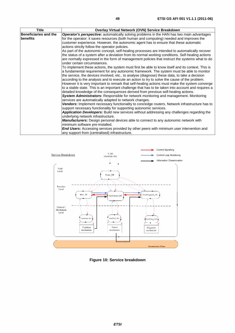
ETSI
ETSI GS AFI 001 V1.1.1 (2011-06) 49
Title Overlay Virtual Network (OVN) Service Breakdown Beneficiaries and the benefits
Operator's perspective: automatically solving problems in the HAN has two main advantages for the operator: it saves resources (both human and computing) needed and improves the customer experience. However, the autonomic agent has to ensure that these automatic actions strictly follow the operator policies. As part of the autonomic concept, self-healing processes are intended to automatically recover the status of a system after a deviation from its normal working conditions. Self-healing actions are normally expressed in the form of management policies that instruct the systems what to do under certain circumstances. To implement these actions, the system must first be able to know itself and its context. This is a fundamental requirement for any autonomic framework. The system must be able to monitor the service, the devices involved, etc., to analyse (diagnose) these data, to take a decision according to the analysis and to execute an action to try to solve the cause of the problem. However it is very important to remark that self-healing actions must make the system converge to a stable state. This is an important challenge that has to be taken into account and requires a detailed knowledge of the consequences derived from previous self-healing actions. System Administrators: Responsible for network monitoring and management. Monitoring services are automatically adapted to network changes. Vendors: Implement necessary functionality to core/edge routers. Network infrastructure has to support necessary functionality for supporting autonomic services. Application Developers: Build new services without addressing any challenges regarding the underlying network infrastructure. Manufacturers: Design personal devices able to connect to any autonomic network with minimum software pre-installed. End Users: Accessing services provided by other peers with minimum user intervention and any support from (centralised) infrastructure.
Figure 10: Service breakdown

ETSI
ETSI GS AFI 001 V1.1.1 (2011-06) 50
5.9 Scenarios Overlay Virtual Network Service Quality Degradation
Table 18: Scenarios Overlay Virtual Network Service Quality Degradation
Title Overlay Virtual Network Service Quality Degradation Description/Story Use Case
As Alan travels, he wants to access content from his HAN, for example video content from his video database. He typically wants to see this content at a particular quality level. This quality level is set in the management policy in the HAN/SOHO Management Device and can be made known to each of the devices in the HAN. When Alan attempts to download information from his HAN to his laptop, the admission control (AC) mechanism (see "Problems" section below for further issues relating to AC) will either prompt Alan or try to enforce conditions predefined in the management policy set up on Alan's HAN. The quality of the end-to-end communication will be iteratively monitored on the source side (period to be configured) and QoS parameters including packet delay, packets dropped, jitter (and others) will be monitored. It is envisaged that an intelligent management application will be deployed in the HAN. The functionality of this application will be responsible for deciding what action to take if/when the communication parameters drop below predetermined thresholds. Note that initial admission control will use only bandwidth as a determining fact; however, iterative monitoring of the link will use available bandwidth along with other QoS connection parameters such as the ones given above. As part of its context aware nature, the autonomic application should sample these parameters more frequently when the QoS is close to one of its thresholds. As well as solving the problem for the viewer at that moment, the management application should try to solve the underlying problem and report any bigger issues to the user. The following cases can be diagnosed: • Congestion in the OVN user HAN, i.e. destination hotel network. In this case, the
management application detects any errors within the hotel network caused by interference between incoming video traffic and other traffic sources (mainly Internet and intra-hotel traffic).
• Congestion in the content source HAN i.e. Alan's HAN. In this case, the management application detects errors within Alan's network due to excessive outgoing traffic caused by the interference between video and other types of traffic.
• The impact on the source HAN of multiple subscriptions to OVN services and the consequent increase in HAN traffic should be taken into account. At the content source HAN, there should be a mechanism to detect if poor QoS within the HAN is caused by the fact that the OVN service is being used. If that was the case, a proper action should be taken (for instance, stopping temporarily the OVN service). This is a very important issue because, it may impact the quality of experience related to the OVN service. Therefore, it may be convenient to split this case into a different scene on its own.
• QoS degradation at the access network. This use case is meant to detect QoS deficiencies in the access network caused by excessive traffic or access network malfunctioning.
• Lack of sufficient available end to end bandwidth. Since several ISP networks can be involved in delivering the OVN service, it might happen that, due to problems in any of these ISPs, the available end to end bandwidth drops below the required threshold.
• Degraded video signal received from the video server. In this case the management application will detect that the video server is delivering a low quality video signal.
Network Environment(s)
Home Area Networks (HAN) Small Office Home Office (SOHO)

ETSI
ETSI GS AFI 001 V1.1.1 (2011-06) 51
Title Overlay Virtual Network Service Quality Degradation Problems Admission Control will primarily be used as a decision making component, which the main role
is to admit or reject a new session trying to access content in the HAN. The Admission Control Managed Entity (AC_ME) (see definition of Managed Entity(ME)) will receive input from the QoS decision element (QoS_DE) (see definition of Decision Element (DE)), which exchanges information with the Application Decision Element (App_DE) in order to define the requirements for a particular session. A tailored AC mechanism decides whether or not a HAN device should accept a new session. Such decision must be concerned basically on two issues: a) Short-term issue: Can the HAN gateway device and the host afford a new session and its
respective requested QoS? Is there enough initial end-to-end (E2E) available bandwidth for transporting a new session? (figure 11)
b) Long-term issue: Will the new session affect the current QoS levels already being held and committed by the HAN gateway? (figure 12)
Information exchange will be kept simple between the AC_ME and its correlated components. Fundamentally, AC_ME needs to receive a traffic specification (TSPEC) for the requested session and will return a reply informing whether such session will be allowed to be initiated, an offer for an alternative QoS level (normally, with less strict QoS requirements), or a direct rejection. TSPECs may follow any standard format, such as TSPECs for Integrated Services or for IEEE 802.11e [i.14]. AC_ME may also follow an interactive negotiation strategy or different parameter description of traffic. In other words, appropriate TSPECs are required from new sessions and the AC_ME will admit only the traffic that satisfies the TSPECs, offer a different TSPEC or reject the connection. AC_ME will be then a mix of traffic descriptor-based and measurement-based AC. After a TSPEC is provided by the QoS_DE for each new session prior to its establishment, a fast E2E available bandwidth technique must be launched in order to have a current view of the network path condition between the content provider host in the HAN and a user device that joined the OVN. Particularly, AC_ME will rely on accurate techniques for estimating the current E2E available bandwidth, such as Pathload, ABGet or IMR-Pathload. This information is then disseminated to the AC_ME where it can make AC decisions to allow the service to proceed as requested. Additional attention may be given to bandwidth fluctuation over multiple time scales (i.e. when the traffic profile shows long-range dependency) in order to avoid overestimation or underestimation of TSPECs, which could lead to QoS degradation, poor HAN resources utilization, or high rate of refused session admission.
Functions Impacted The following autonomic functions are impacted: • Self-optimisation – data and services are distributed uniformly among the participating
nodes. The established overlay topology is maintained and updated after changes in the network.
Systems Involved Operators ISP Source and Destination access networks Core/Edge Routers HAN devices – Home Gateway, End User Devices
Indicators / Evaluation criteria / Metrics
1) How is the autonomic application installed and updated on the HAN Management Device?
2) How are the control mechanisms installed and updated on the other HAN Devices such as the travelling laptop?
3) Will content providers be willing to provide available bandwidth information to end-user applications in their networks? What agreement needs to be set up to allow the user to get this information?
4) Availability and cost of probes inside the HAN.
5) Performance of QoS monitoring components deployed in HAN devices.
6) Privacy issues when accessing customers' traffic. Players Network Operator; Vendors/ Manufacturers; End Users Beneficiaries and the benefits
Operator's perspective: Being able to proactively diagnose and solve QoS problems in the HAN would be a very good way to increase customer satisfaction. This has to be balanced with the cost of deploying QoS monitoring components inside the HAN. This scene directly involves the operator. The admission control mechanism extends from the HAN/SOHO Management Device to the User device. The operator is required to carry the bandwidth determination criteria and the control packets (as well as the content). The control packets will allow the user device (in this case, the laptop) to inform the HAN/SOHO Management Device in an ongoing manner of the video quality being received.
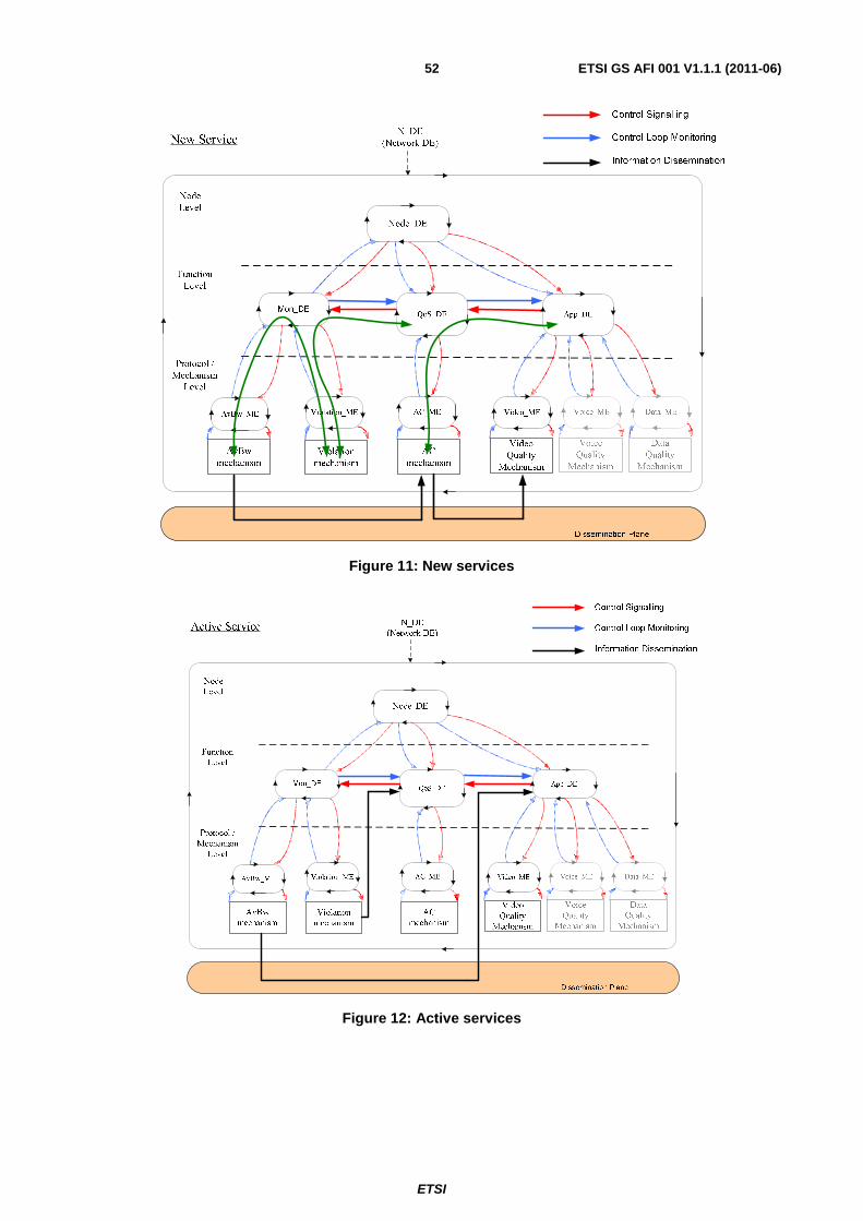
ETSI
ETSI GS AFI 001 V1.1.1 (2011-06) 52
Figure 11: New services
Figure 12: Active services

ETSI
ETSI GS AFI 001 V1.1.1 (2011-06) 53
5.10 Monitoring in Carrier Grade Wireless Mesh Networks
Table 19: Monitoring in Carrier Grade Wireless Mesh Networks
Title Monitoring in Carrier Grade Wireless Mesh Networks (CARMEN) Description/Story Use Case
Mesh networking technology provides a cost effective and efficient alternative for realising backhaul networks to provide mobile users with high quality services. Wireless mesh networks are dynamically self-organised and self-configured, which ultimately results in reduced deployment costs and lower network maintenance costs for the operator. We focus on mesh networks which provide carrier grade services with low operational maintenance, low cost and high flexibility in deployment. Furthermore, we focus on continuous monitoring features, which allow self-configuration and self-healing properties reducing the maintenance cost of the infrastructure. The monitoring system plays a critical role in supporting the self-* functionality. The main role of the monitoring system is to supply other modules with accurate and timely information regarding the status of the network in both a technology-dependent and technology–independent manner. Specifically this requires measurement, aggregation, correlation and statistical analysis of the raw data. The reports from the monitoring system are not only crucial for self-configuration and planning functions, but also important for dynamic resource management, such as routing updates or admission control decisions. Steps: 1) After a mesh node is activated, the node starts discovering its radio neighbourhood as
seen by each of its multiple radio interfaces of different technologies. This is based on passive scanning by the monitoring function and facilitates the discovery of the mesh gateway node.
2) The monitoring function supplies the necessary information to create a view of the physical network topology. This view describes which radio interfaces can be used by two neighbouring mesh nodes to communicate with each other.
3) The monitoring function gathers information on the level of potential interference between radio links as well as interference resulting from external sources.
4) This information drives other mesh network functionalities, such as network planning, radio resource management, routing, mobility management, etc.
5) During the operation of the network, the monitoring function continuously measures network performance characteristics and reports any deviation so that corrective action can be taken.
EXAMPLE: City coverage scenario – a wireless mesh network is deployed in selected areas of a city centre to provide users access to the operator's services. The mesh network consists of a small group of nodes which are connected into the operator's wired infrastructure and a larger number of wireless nodes. The self-configuration functionality allows easy network deployment and extendibility. Constant monitoring assures an accurate view of the physical network topology and aids in radio management, especially in dense urban environments.
Network Environment(s)
Wireless mesh network (heterogeneous, multi-hop, robust topology with dedicated mesh routers), support for carrier grade services
Problems 1) Determining network capacity (e.g. available radio channels)
2) Determining link quality (e.g. bandwidth, delay)
3) Detecting neighbouring nodes (passively)
4) Allowing prompt reaction to network events (e.g. link failure)
5) Utilizing heterogeneous network technologies Functions Impacted The following autonomic functionalities are provided:
1) Self-configuration of the mesh nodes. Each mesh node recognizes the physical network topology, identifies its neighbours, and utilizes heterogeneous network technologies. This is performed in particular during the initial bootstrapping phase.
2) Self-organization of the network. The whole network and all communication links between mesh nodes are established.
3) Self-healing. The network is robust to changes of topology and radio conditions. Systems Involved Core/edge wireless mesh routers

ETSI
ETSI GS AFI 001 V1.1.1 (2011-06) 54
Title Monitoring in Carrier Grade Wireless Mesh Networks (CARMEN) Indicators / Evaluation criteria / Metrics
1) How much resource (in terms of memory, interfaces, computational power) does monitoring require?
2) How long should monitoring data be stored at a node?
3) How long does it take to notice link changes?
4) What is the accuracy of a link failure prediction?
5) How long does it take to detect neighbouring nodes? Players Network Operators: deploy wireless mesh networks
Vendors/Manufacturers: provide equipment supporting carrier grade services in wireless mesh networks
Beneficiaries Network Operators: can easily deploy new networks, extend existing networks, and assure QoS to meet users' expectations at a reduced cost End-users: gain access to triple-play services (with a required level of QoS) through a ubiquitous wireless network

ETSI
ETSI GS AFI 001 V1.1.1 (2011-06) 55
5.11 Network self-management based on capabilities of network behaviours as described to the overlying OSS processes
Table 20: Network self-management based on capabilities of network behaviours as described to the overlying OSS processes
Title Network self-management based on capabilities of network behaviours as described to the overlying OSS processes
Description/Story Use Case
Nowadays, the technologies often run far ahead of the ability to manage them. This may result in complex networked systems requiring manual configuration and dedicated management provided by very expensive experts. Such a model is obviously cost ineffective and it cannot scale. For this reason there is an urgent need for automation in terms of planning, configuring and assuring network behaviours. Next generation Operations Support Systems (OSS) need to be able to manage a diverse set of network devices offering different capabilities and exposing various behaviours. In particular some of the devices might be equipped with capabilities allowing for certain cooperative and non-cooperative behaviours. Currently developed next generation networks often assume the possibility of having devices able to route data in a cooperative manner to increase the QoS offered by the system. Such devices are preliminarily to be deployed by network operators as fixed, movable and mobile ones, while the mobile relay nodes may be also user devices on a longer perspective. It puts then certain requirements on the system to be able to discover the capabilities of distinct devices and use the acquired information for the purposes of exploiting these behaviours whenever beneficiary for the overall performance. This task involves other OSS level routines such as inventory management and service assurance.
Network Environment(s)
Wireless mobile networks
Problems One of the aspects that seems to be missing in terms of the desirable behaviours is any consideration of what is the cost of ownership of a given behaviour in the context of planning, fulfilling/configuring and assuring this behaviour in the end to end system. It is very easy to create a network feature that is bespoke and therefore difficult to integrate and from an OSS point of view the need would be to understand how the capabilities of network behaviours can be described in a common standardised way that makes them easy to integrate and describe to the overlying OSS processes. The aforementioned cooperative behaviour can be highly beneficial from the system performance perspective, however, it comes at a certain cost. This cost may result from the fact that either: • additional network operator devices may need to be deployed so they can be
automatically configured to expose cooperative behaviours when there is a need, • user devices may be needed to instantiate cooperation and in that case users may want to
trade what they can offer for some other privileges or benefits. There is then a need for a logic that would be able to analyse applicability of such a behaviour for specific deployment and in given circumstances (longer term perspective) and consequently make use of them by imposing certain policies. It might turn out that in some cases cooperative behaviours can be translated into revenue, as well as they can add to service assurance. In different circumstances different cooperative behaviours may be exposed: - Base Station/Access Point can instantiate cooperation with Relay Node(s), - Relay Nodes can instantiate cooperation among themselves. Otherwise non-cooperative behaviour may be advantageous.
Functions Impacted Service assurance Inventory management
Systems Involved OSS Indicators / Evaluation criteria / Metrics
Cost of ownership of a behaviour – how capabilities of network behaviours can be described in a common standardised way that makes them easy to integrate and describe to the overlying OSS processes.
Players Software solutions providers Service providers
Beneficiaries Network operators (in terms of service provision) End users (in terms of the QoS offered)

ETSI
ETSI GS AFI 001 V1.1.1 (2011-06) 56
5.12 Scenarios, requirements and references relationship To sum up, table 21 lists the relationships between Scenarios and derived requirements. It also mentions the references (European Research projects, SDOs) if any.
Table 21: Use cases, Scenarios and references relationships
Scenarios Requirement Identifier: RQ ID Reference Agreed AFI #04 meeting
Scenario 5.2 Autonomics in NGN
5, 9, 10, 24, 25, 26, 27, 28, 32, 33, 34, 35, 36, 37, 38, 39, 40, 41, 42, 43, 44, 45, 47, 48, 51, 52, 53, 54, 55, 56, 57, 58, 59, 60, 61, 62, 63, 64
[i.11], [i.10], [i.12] 3 operators
Scenario 5.3 Auto-configuration of Routers
21, 22, 23, 33, 39 [i.8]
Scenario 5.4 Self-Management of Coverage/Capacity in Wireless systems
2, 24, 27, 28, 34, 35, 36, 37, 49, 53, 54, 55, 58, 60, 62, 63
Scenario 5.5 Cognitive event management
34, 53, 54, 55, 58, 59, 60, 61, 63
Scenario 5.6 Coordination of Self *
Scenario 5.7 Autonomic network monitoring
1, 2, 3, 4, 6, 7, 8, 11, 12, 13, 14, 15, 16, 17, 18, 19, 20, 46, 49, 50 21, 22, 23, 25, 26, 27, 28, 29, 30, 34, 35, 36, 64, 67, 68, 69
Scenario 5.8 Overlay Virtual Network (Service Breakdown)
[i.8]
Scenario 5.9 Overlay Virtual Network (Service quality degradation)
[i.8]
Scenario 5.10 Monitoring in Carrier Grade Wireless Mesh networks
29, 30, 31 [i.9]
Scenario 5.11 Network Self-management by Overlying OSS processes

ETSI
ETSI GS AFI 001 V1.1.1 (2011-06) 57
Annex A (informative): Authors & contributors The following people have contributed to the present document.
Rapporteur: Tayeb Ben Meriem, Orange / France Telecom Other contributors:
First Name Last Name Company Benoit Radier Orange / France Telecom José Antonio Lozano López Telefonica Juan Manuel González Muñoz Telefonica Ranganai Chaparadza Fokus, Fraunhofer Antonio Manzalini Telecom Italia (TI) Corrado Moiso Telecom Italia (TI) Michał Wódczak Telcordia Technologies Szymon Szott AGH University of Science and Technology Katarzyna Kosek-Szott AGH University of Science and Technology Marek Natkaniec AGH University of Science and Technology Brian Lee Athlone Institute of Technology Kevin Quinn Waterford Institute of Technology Laurent Ciavaglia Alcatel-Lucent Jesse Kielthy Waterford Institute of Technology Maurice Duault Cisco systems Athanassios Liakopoulos GRNET Anastasios Zafeiropoulos GRNET Panagiotis Gouvas GRNET/ UBITECH Nancy Alonistioti NKUA, University of Athens Apostolos Kousaridas NKUA, University of Athens, University of Athens Tilemachos Raptis NKUA, University of Athens Vangelis Gazis NKUA, University of Athens Panagiotis Demestichas UPRC Kostas Tsagkaris UPRC Maria Akezidou UPRC Marios Logothetis UPRC

ETSI
ETSI GS AFI 001 V1.1.1 (2011-06) 58
Annex B (informative): Acknowledgements The AFI very much acknowledges the European Commission (EC), which is funding a number of FP7 projects under the umbrella "Network of the Future" like EFIPSANS http://www.efipsans.org (some partners of which founded AFI together with some non-EFIPSANS partners), and many other FP7 projects that are represented in AFI and are making contributions to AFI, such as Self-NET http://www.ict-selfnet.eu/, E3 https://www.ict-e3.eu, CARMEN project (http://www.ist-carmen.eu/, UNIVERSELF project. http://www.ict-univerself.eu). Also, non-EC funded projects contributing to AFI are acknowledged.

ETSI
ETSI GS AFI 001 V1.1.1 (2011-06) 59
Annex C (informative): Bibliography Heylighen F. (2009): "Complexity and Self-organization", in Encyclopaedia of Library and Information Sciences, eds. M. J. Bates & M. N. Maack (CRC Press).
V. Poladian et al,: "Dynamic Configuration of Resource-Aware Services" Proc. 24th Int. Conf. Software Engineering, pp. 604-613, May 2004.
http://en.wikipedia.org/wiki/Autonomic-Networking.
J. O. Kephart, D. M. Chess: "The Vision of Autonomic Computing", January 2003 http://www.research.ibm.com/autonomic/research/papers/AC-Vision-Computer-Jan-2003.pdf.
ETSI TS 188 003 (V1.1.1): "Telecommunications and Internet Converged Services and Protocols for Advanced Networking (TISPAN); OSS requirements; OSS definition of requirements and priorities for further network management specifications for NGNOSS definition of requirements and priorities for further network management specifications for NGN".
EC Funded Self-NET Project: "Self-Management of Cognitive Future InterNET Elements" https://www.ict-selfnet.eu/ http://cordis.europa.eu/fetch?CALLER=PROJ-ICT&ACTION=D&CAT=PROJ&RCN=86636.
EC funded FP7 E3 Project: "End-to-End Efficiency" https://ict-e3.eu/.
EC funded FP7 SOCRATES Project: "Self-Optimisation and self-ConfiguRATion in wirelEss network" http://www.fp7-socrates.org/.
EC funded FP7 4WARD Project http://www.4ward-project.eu/.
EC Funded FP7 ANA Project: "Autonomic Network Architecture" http://www.ana-project.org/.
ETSI TS 132 500 (V10.1.0): "Universal Mobile Telecommunications System (UMTS); LTE; Telecommunication management; Self-Organizing Networks (SON); Concepts and requirements (3GPP TS 32.500 version 10.1.0 Release 10)".

ETSI
ETSI GS AFI 001 V1.1.1 (2011-06) 60
History
Document history
V1.1.1 June 2011 Publication