ethernet/ip for grundfos pumpsnet.grundfos.com/appl/ccmsservices/public/literature/...• cim/ciu...
TRANSCRIPT
EtherNet/IP for Grundfos pumpsCIM/CIU 500 Ethernet
Functional profile and user manual
GRUNDFOS INSTRUCTIONS
En
glis
h (G
B)
English (GB) Functional profile and user manual
Original functional profile and user manual.
This functional profile describes Grundfos EtherNet/IP for pumps.
CONTENTSPage
1. General information
1.1 Hazard statements
The symbols and hazard statements below may appear in Grundfos installation and operating instructions, safety instructions and service instructions.
The hazard statements are structured in the following way:
1.2 Notes
The symbols and notes below may appear in Grundfos installation and operating instructions, safety instructions and service instructions.
1. General information 21.1 Hazard statements 21.2 Notes 2
2. Introduction 32.1 About this functional profile 32.2 EDS file 32.3 Assumptions 32.4 Definitions and abbreviations 3
3. System description 3
4. Specifications 44.1 CIM module 44.2 CIM 500 Ethernet 44.3 EtherNet/IP 5
5. EtherNet/IP, CIM 500 setup 65.1 Connecting the Ethernet cable 65.2 Selection of Industrial Ethernet protocol 65.3 Setting the IP addresses 65.4 Establishing a connection to the webserver 75.5 Status LEDs 75.6 DATA and LINK LEDs 7
6. Detailed description of data parameters 86.1 Connection and assembly overview 86.2 Control parameters, output assembly 11 96.3 Configuration parameters, Input/Output explicit
messaging 136.4 Dynamic status parameters, input assembly 2 136.5 Illustration of closed-loop control 166.6 Alarms and warnings 176.7 Static status parameters, input assembly 3 186.8 Measured parameters, input assembly 4 196.9 Sensor-dependent measurements 216.10 Special parameter, input explicit messaging 22
7. Product simulation 22
8. Fault finding the product 238.1 EtherNet/IP 23
9. Disposing of the product 23
Read this document before installing the product. Installation and operation must comply with local regulations and accepted codes of good practice.
DANGER
Indicates a hazardous situation which, if not avoided, will result in death or serious personal injury.
WARNING
Indicates a hazardous situation which, if not avoided, could result in death or serious personal injury.
CAUTION
Indicates a hazardous situation which, if not avoided, could result in minor or moderate personal injury.
SIGNAL WORD
Description of hazard
Consequence of ignoring the warning.- Action to avoid the hazard.
Observe these instructions for explosion-proof products.
A blue or grey circle with a white graphical symbol indicates that an action must be taken.
A red or grey circle with a diagonal bar, possibly with a black graphical symbol, indicates that an action must not be taken or must be stopped.
If these instructions are not observed, it may result in malfunction or damage to the equipment.
Tips and advice that make the work easier.
2
En
gli
sh
(G
B)
2. Introduction2.1 About this functional profile
This functional profile describes the following modules and units:
• CIM/CIU 500 Ethernet for EtherNet/IP.
This functional profile applies to the following Grundfos products:
• Grundfos CRE/CRNE/CRIE, MTRE, CHIE, CME
• Grundfos TPE, TPE Series 2000, TPE3, NBE/NKE
• Grundfos CUE drive
• Grundfos MAGNA3.
In the following, the supported products are referred to as "E-pump".
Grundfos cannot be held responsible for any problems caused directly or indirectly by using information in this functional profile.
2.2 EDS file
For this product, an associated Electronic Data Sheet file (Grundfos_EIP_Pump_Adapter_EDS.eds) can be downloaded from the Grundfos Product Center.
2.3 Assumptions
This functional profile assumes that the reader is familiar with commissioning and programming of EtherNet/IP devices.
2.4 Definitions and abbreviations
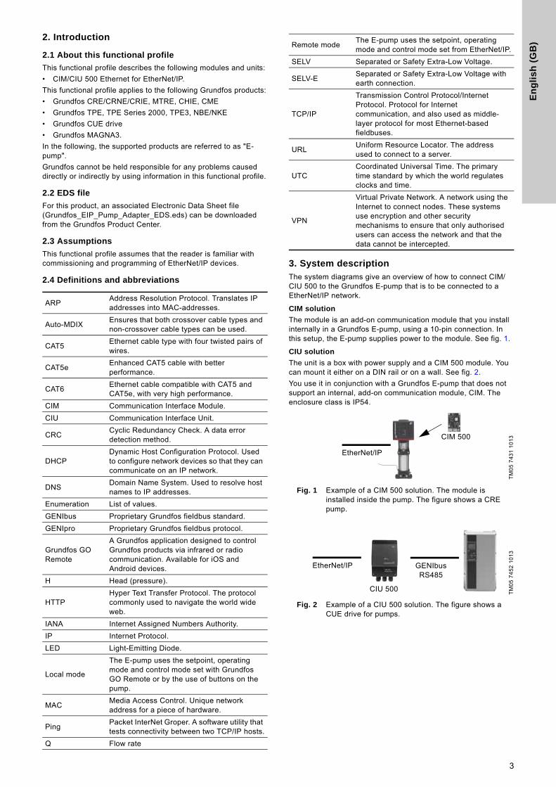
3. System descriptionThe system diagrams give an overview of how to connect CIM/CIU 500 to the Grundfos E-pump that is to be connected to a EtherNet/IP network.
CIM solution
The module is an add-on communication module that you install internally in a Grundfos E-pump, using a 10-pin connection. In this setup, the E-pump supplies power to the module. See fig. 1.
CIU solution
The unit is a box with power supply and a CIM 500 module. You can mount it either on a DIN rail or on a wall. See fig. 2.
You use it in conjunction with a Grundfos E-pump that does not support an internal, add-on communication module, CIM. The enclosure class is IP54.
Fig. 1 Example of a CIM 500 solution. The module is installed inside the pump. The figure shows a CRE pump.
Fig. 2 Example of a CIU 500 solution. The figure shows a CUE drive for pumps.
ARPAddress Resolution Protocol. Translates IP addresses into MAC-addresses.
Auto-MDIXEnsures that both crossover cable types and non-crossover cable types can be used.
CAT5Ethernet cable type with four twisted pairs of wires.
CAT5eEnhanced CAT5 cable with better performance.
CAT6Ethernet cable compatible with CAT5 and CAT5e, with very high performance.
CIM Communication Interface Module.
CIU Communication Interface Unit.
CRCCyclic Redundancy Check. A data error detection method.
DHCPDynamic Host Configuration Protocol. Used to configure network devices so that they can communicate on an IP network.
DNSDomain Name System. Used to resolve host names to IP addresses.
Enumeration List of values.
GENIbus Proprietary Grundfos fieldbus standard.
GENIpro Proprietary Grundfos fieldbus protocol.
Grundfos GO Remote
A Grundfos application designed to control Grundfos products via infrared or radio communication. Available for iOS and Android devices.
H Head (pressure).
HTTPHyper Text Transfer Protocol. The protocol commonly used to navigate the world wide web.
IANA Internet Assigned Numbers Authority.
IP Internet Protocol.
LED Light-Emitting Diode.
Local mode
The E-pump uses the setpoint, operating mode and control mode set with Grundfos GO Remote or by the use of buttons on the pump.
MACMedia Access Control. Unique network address for a piece of hardware.
PingPacket InterNet Groper. A software utility that tests connectivity between two TCP/IP hosts.
Q Flow rate
Remote modeThe E-pump uses the setpoint, operating mode and control mode set from EtherNet/IP.
SELV Separated or Safety Extra-Low Voltage.
SELV-ESeparated or Safety Extra-Low Voltage with earth connection.
TCP/IP
Transmission Control Protocol/Internet Protocol. Protocol for Internet communication, and also used as middle-layer protocol for most Ethernet-based fieldbuses.
URLUniform Resource Locator. The address used to connect to a server.
UTCCoordinated Universal Time. The primary time standard by which the world regulates clocks and time.
VPN
Virtual Private Network. A network using the Internet to connect nodes. These systems use encryption and other security mechanisms to ensure that only authorised users can access the network and that the data cannot be intercepted.
TM
05
74
31
10
13
TM
05
74
52
10
13
EtherNet/IP
CIM 500
EtherNet/IP GENIbus RS485
CIU 500
3
En
glis
h (G
B)
4. Specifications
4.1 CIM module
4.2 CIM 500 Ethernet
General data Description Comments
Ambient humidity 30-95 % Relative, non-condensing.
Operating temperature -20 to +45 °C
Storage temperature -25 to +70 °C
GENIbus visual diagnostics LED2
The LED will be in one of these states:Off, permanently green, flashing red, permanently red.See section 5.5 Status LEDs.
Power supply (CIU) 24-240 V Integrated in the unit.
GENIbus connection type (CIU) RS-485, 3-wire + screen Conductors: A, B and Y.
CIU box enclosure class IP54
CIU box dimensions (H x W x D) 182 x 108 x 82 mm
CIM 500 Ethernet specifications Description Comments
Application layerDHCP, HTTP, Ping, FTP, SMTP, SNTP, fieldbus protocols
Transport layer TCP
Internet layer Internet protocol V4 (IPv4)
Link layer ARP, Media Access Control (Ethernet)
Ethernet cable CAT5, CAT5e or CAT6Supports auto cable-crossover detecting (Auto-MDIX).
Maximum cable length 100 metres at 10/100 Mbits/s Corresponds to 328 feet.
Transmission speed 10 Mbits/s, 100 Mbits/s Auto-detected.
Industrial Ethernet fieldbus protocolsPROFINET IO, Modbus TCP, BACnet IP, EtherNet/IP, GRM IP, Grundfos iSolutions Cloud
Selected with rotary switch. See section 5.2 Selection of Industrial Ethernet protocol.
4
En
gli
sh
(G
B)
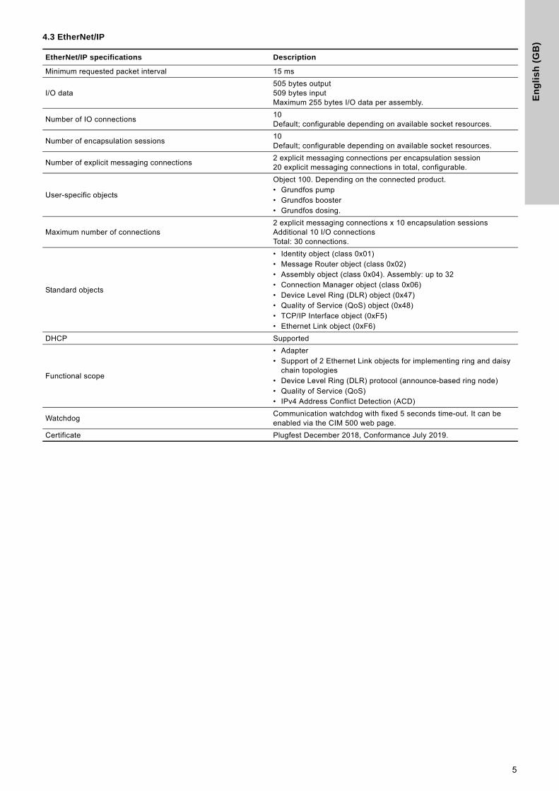
4.3 EtherNet/IP
EtherNet/IP specifications Description
Minimum requested packet interval 15 ms
I/O data505 bytes output509 bytes inputMaximum 255 bytes I/O data per assembly.
Number of IO connections10 Default; configurable depending on available socket resources.
Number of encapsulation sessions10 Default; configurable depending on available socket resources.
Number of explicit messaging connections2 explicit messaging connections per encapsulation session20 explicit messaging connections in total, configurable.
User-specific objects
Object 100. Depending on the connected product.• Grundfos pump• Grundfos booster• Grundfos dosing.
Maximum number of connections2 explicit messaging connections x 10 encapsulation sessionsAdditional 10 I/O connectionsTotal: 30 connections.
Standard objects
• Identity object (class 0x01)• Message Router object (class 0x02) • Assembly object (class 0x04). Assembly: up to 32• Connection Manager object (class 0x06)• Device Level Ring (DLR) object (0x47)• Quality of Service (QoS) object (0x48)• TCP/IP Interface object (0xF5)• Ethernet Link object (0xF6)
DHCP Supported
Functional scope
• Adapter• Support of 2 Ethernet Link objects for implementing ring and daisy
chain topologies• Device Level Ring (DLR) protocol (announce-based ring node)• Quality of Service (QoS)• IPv4 Address Conflict Detection (ACD)
WatchdogCommunication watchdog with fixed 5 seconds time-out. It can be enabled via the CIM 500 web page.
Certificate Plugfest December 2018, Conformance July 2019.
5
En
glis
h (G
B)
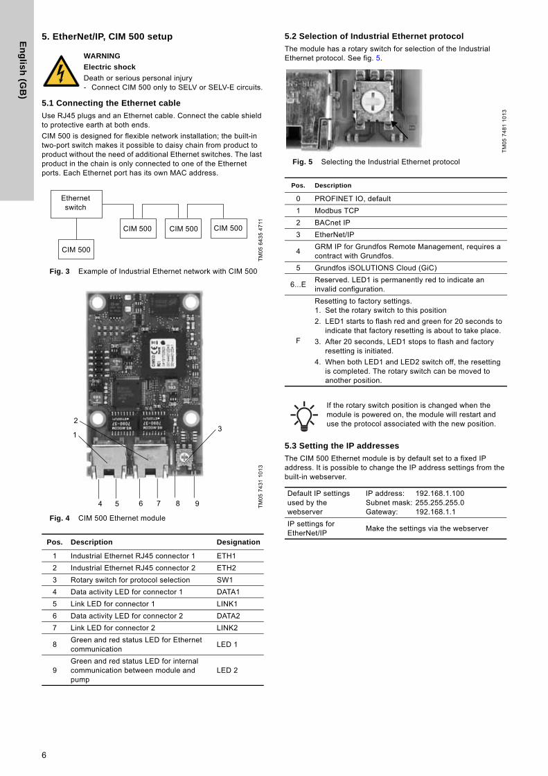
5. EtherNet/IP, CIM 500 setup
5.1 Connecting the Ethernet cable
Use RJ45 plugs and an Ethernet cable. Connect the cable shield to protective earth at both ends.
CIM 500 is designed for flexible network installation; the built-in two-port switch makes it possible to daisy chain from product to product without the need of additional Ethernet switches. The last product in the chain is only connected to one of the Ethernet ports. Each Ethernet port has its own MAC address.
Fig. 3 Example of Industrial Ethernet network with CIM 500
Fig. 4 CIM 500 Ethernet module
5.2 Selection of Industrial Ethernet protocol
The module has a rotary switch for selection of the Industrial Ethernet protocol. See fig. 5.
Fig. 5 Selecting the Industrial Ethernet protocol
5.3 Setting the IP addresses
The CIM 500 Ethernet module is by default set to a fixed IP address. It is possible to change the IP address settings from the built-in webserver.
WARNING
Electric shock
Death or serious personal injury- Connect CIM 500 only to SELV or SELV-E circuits.
TM
05
64
35
47
11T
M0
5 7
43
1 1
01
3
Pos. Description Designation
1 Industrial Ethernet RJ45 connector 1 ETH1
2 Industrial Ethernet RJ45 connector 2 ETH2
3 Rotary switch for protocol selection SW1
4 Data activity LED for connector 1 DATA1
5 Link LED for connector 1 LINK1
6 Data activity LED for connector 2 DATA2
7 Link LED for connector 2 LINK2
8Green and red status LED for Ethernet communication
LED 1
9Green and red status LED for internal communication between module and pump
LED 2
Ethernet switch
CIM 500 CIM 500 CIM 500
CIM 500
1
23
8 94 75 6T
M0
5 7
48
1 1
01
3
Pos. Description
0 PROFINET IO, default
1 Modbus TCP
2 BACnet IP
3 EtherNet/IP
4GRM IP for Grundfos Remote Management, requires a contract with Grundfos.
5 Grundfos iSOLUTIONS Cloud (GiC)
6...EReserved. LED1 is permanently red to indicate an invalid configuration.
F
Resetting to factory settings.1. Set the rotary switch to this position
2. LED1 starts to flash red and green for 20 seconds to indicate that factory resetting is about to take place.
3. After 20 seconds, LED1 stops to flash and factory resetting is initiated.
4. When both LED1 and LED2 switch off, the resetting is completed. The rotary switch can be moved to another position.
If the rotary switch position is changed when the module is powered on, the module will restart and use the protocol associated with the new position.
Default IP settings used by the webserver
IP address: 192.168.1.100Subnet mask: 255.255.255.0Gateway: 192.168.1.1
IP settings for EtherNet/IP
Make the settings via the webserver
6
En
gli
sh
(G
B)
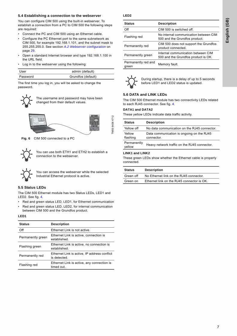
5.4 Establishing a connection to the webserver
You can configure CIM 500 using the built-in webserver. To establish a connection from a PC to CIM 500 the following steps are required:
• Connect the PC and CIM 500 using an Ethernet cable.
• Configure the PC Ethernet port to the same subnetwork as CIM 500, for example 192.168.1.101, and the subnet mask to 255.255.255.0. See section A.2 Webserver configuration on page 29.
• Open a standard Internet browser and type 192.168.1.100 in the URL field.
• Log in to the webserver using the following:
The first time you log in, you will be asked to change the password.
Fig. 6 CIM 500 connected to a PC
5.5 Status LEDs
The CIM 500 Ethernet module has two Status LEDs, LED1 and LED2. See fig. 4.
• Red and green status LED, LED1, for Ethernet communication
• Red and green status LED, LED2, for internal communication between CIM 500 and the Grundfos product.
LED1
LED2
5.6 DATA and LINK LEDs
The CIM 500 Ethernet module has two connectivity LEDs related to each RJ45 connector. See fig. 4.
DATA1 and DATA2
These yellow LEDs indicate data traffic activity.
LINK1 and LINK2
These green LEDs show whether the Ethernet cable is properly connected.
User admin (default)
Password Grundfos (default)
The username and password may have been changed from their default values.
TM
05
64
36
47
12
You can use both ETH1 and ETH2 to establish a connection to the webserver.
You can access the webserver while the selected Industrial Ethernet protocol is active.
Status Description
Off Ethernet Link is not active.
Permanently greenEthernet Link is active, connection is established.
Flashing greenEthernet Link is active, no connection is established.
Permanently redEthernet Link is active, IP address conflict is detected.
Flashing redEthernet Link is active, any connection is timed out.
Status Description
Off CIM 500 is switched off.
Flashing redNo internal communication between CIM 500 and the Grundfos product.
Permanently redCIM 500 does not support the Grundfos product connected.
Permanently greenInternal communication between CIM 500 and the Grundfos product is OK.
Permanently red and green
Memory fault.
During startup, there is a delay of up to 5 seconds before LED1 and LED2 status is updated.
Status Description
Yellow off No data communication on the RJ45 connector.
Yellow flashing
Data communication is ongoing on the RJ45 connector.
Permanently yellow
Heavy network traffic on the RJ45 connector.
Status Description
Green off No Ethernet link on the RJ45 connector.
Green on Ethernet link on the RJ45 connector is OK.
7
En
glis
h (G
B)
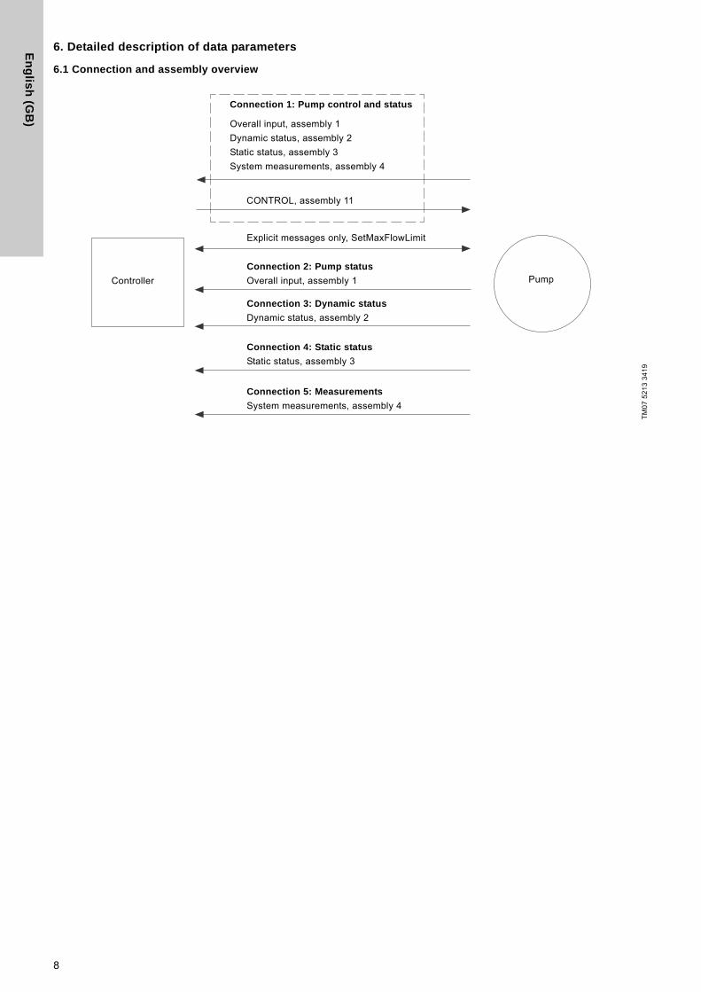
6. Detailed description of data parameters
6.1 Connection and assembly overview
TM
07
52
13
34
19
Pump
Connection 1: Pump control and status
Overall input, assembly 1
Dynamic status, assembly 2
Static status, assembly 3
System measurements, assembly 4
Explicit messages only, SetMaxFlowLimit
Connection 2: Pump status
Overall input, assembly 1
Connection 3: Dynamic status
Dynamic status, assembly 2
Connection 4: Static status
Static status, assembly 3
Connection 5: Measurements
System measurements, assembly 4
CONTROL, assembly 11
Controller
8
En
gli
sh
(G
B)
6.2 Control parameters, output assembly 11
Table legend
CUE: Pumps with CUE drive only.
MGE: Pumps with MGE motor only.
H: Only available on model H and later versions.
S: Sensor required.
●: Always available.
*: If the E-pump is a TPE3 or a TPE Series 2000, the value is estimated and always available.
Pa
ram
ete
r Name Data type ScalingRange/Resolution Description
MG
E 0
.25
- 7
.5 k
W
MG
E 1
1-2
2 k
W
+ C
UE
MA
GN
A3
1 SetRemoteLocal SINT8, 0xC2 Bool (state)0, 1
Setting of Remote/Local state ● ● ●
2 SetOnOff SINT8, 0xC2 Bool (state) 0, 1 Setting of On/Off state ● ● ●3 SetCopyToLocal SINT8, 0xC2 Bool (state) 0, 1 Setting of Copy to local state H CUE ●4 SetRelayOutput1 SINT8, 0xC2 Bool (state) 0, 1 Setting of Relay output 1 ● ● -
5 SetRelayOutput2 SINT8, 0xC2 Bool (state) 0, 1 Setting of Relay output 2 ● ● -
6 SetRelayOutput3 SINT8, 0xC2 Bool (state) 0, 1 Setting of Relay output 3 H - -
7 SetRelayOutput4 SINT8, 0xC2 Bool (state) 0, 1 Setting of Relay output 4 H - -
8 TrigResetAlarm SINT8, 0xC2 Bool (event) ↑ 1 (edge)Command: Triggers alarms reset ● ● ●
9 SetReserved1 SINT8, 0xC2 Bool 0, 1 Reserved - - -
10 SetReserved2 SINT8, 0xC2 Bool 0, 1 Reserved - - -
20 SetControlMode SINT16, 0xC3 Enum 0-255
Select Control mode
0: Constant Speed ● ● ●1: Constant Frequency ● ● ●3: Constant Head S S ●4: Constant Pressure S S ●5: Constant Diff. Pressure H+S - -
6: Proportional Pressure S S ●7: Constant Flow H+S* - ●8: Constant Temperature H+S - ●9: Constant Temp. Difference H+S - S
10: Constant Level H+S - -
128: Auto-Adaption S MGE ●129: Flow Adaption H+S - ●130: Closed Loop Sensor Control
H+S - -
21 SetOperatingMode SINT16, 0xC3 Enum 0-255
Select Operating mode
0: AutoControl ● ● ●4: Minimum ● ● ●6: Maximum ● ● ●
30 SetSetpoint SINT16, 0xC3 0.01 % 0 - 327.67 % Setting of SetSetpoint ● ● ●40 SetRTCValue SINT32, 0xC4 Unix time 0 - (231-1) s Setting of Real Time Clock H - ●
9
En
glis
h (G
B)
6.2.1 Explanation to event trigger
Rising edge
Control bits with a rising-edge event trigger behave like a command that is executed when a bit transition from "0" to "1" occurs. Each of them has a corresponding acknowledge bit in parameter 100, which is set when the command is executed, and cleared when the control bit is written back to "0".
State
Control bits with a state event trigger behave like a "state" that is forced upon the E-pump. In the CIM 500 module, the "actual state" of the E-pump is continuously compared with the "requested" state in the control bits, and the module writes the appropriate GENIbus command to the E-pump to make the two states correspond to each other. Due to state restrictions or priorities, this might not always be possible, see the explanation to the bit in question.
6.2.2 Explanation to control bits
SetRemoteLocal
Control bit for setting the E-pump in remote mode (controlled from the bus), or in local mode (controlled from the operating panel or Grundfos GO Remote):
However, certain commands from other control sources, for example Stop or Max. from a local source or external Stop from a digital input, have a higher priority and overrule the control from the bus. The RemoteLocal status bit will have the value "0" if this is the case. See section 6.4.1 Explanation to the dynamic status parameters.
SetOnOff
Control bit used to start and stop the E-pump:
SetCopyToLocal
Control bit for making the E-pump copy its remote settings for the operating mode, setpoint and control mode to its local settings. Whenever this bit is set, switching the E-pump from remote to local, like the EtherNet/IP watchdog does, will not influence the behaviour of the E-pump.
Copy of Control Context, which is Control mode, Operating mode, On/Off and SetSetpoint, from the remote settings to the local settings takes place when CopyToLocal has been enabled, but only during a Remote->Local transition.It is necessary to introduce such a transition whenever the user wants the local setting to be updated and stored in the EEPROM in the E-pump.
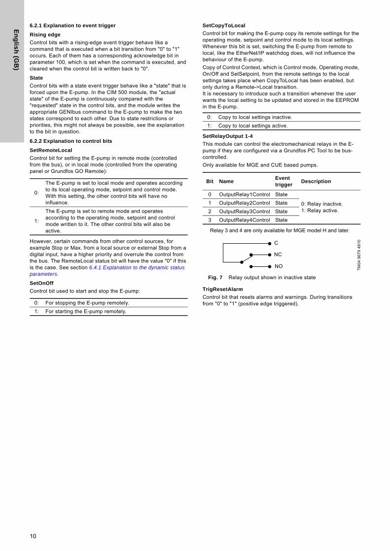
SetRelayOutput 1-4
This module can control the electromechanical relays in the E-pump if they are configured via a Grundfos PC Tool to be bus-controlled.
Only available for MGE and CUE based pumps.
Relay 3 and 4 are only available for MGE model H and later.
Fig. 7 Relay output shown in inactive state
TrigResetAlarm
Control bit that resets alarms and warnings. During transitions from "0" to "1" (positive edge triggered).
0:
The E-pump is set to local mode and operates according to its local operating mode, setpoint and control mode. With this setting, the other control bits will have no influence.
1:
The E-pump is set to remote mode and operates according to the operating mode, setpoint and control mode written to it. The other control bits will also be active.
0: For stopping the E-pump remotely.
1: For starting the E-pump remotely.
0: Copy to local settings inactive.
1: Copy to local settings active.
Bit NameEvent trigger
Description
0 OutputRelay1Control State
0: Relay inactive.1: Relay active.
1 OutputRelay2Control State
2 OutputRelay3Control State
3 OutputRelay4Control State
TM
04
96
79
49
10C
NC
NO
10
En
gli
sh
(G
B)
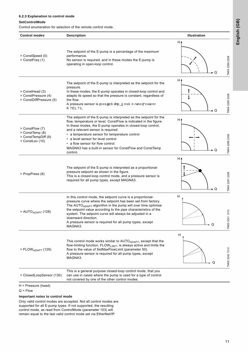
6.2.3 Explanation to control mode
SetControlMode
Control enumeration for selection of the remote control mode.
H = Pressure (head)
Q = Flow
Important notes to control mode
Only valid control modes are accepted. Not all control modes are supported for all E-pump types. If not supported, the resulting control mode, as read from ControlMode (parameter 103) will remain equal to the last valid control mode set via EtherNet/IP.
Control modes Description Illustration
> ConstSpeed (0)> ConstFreq (1)
The setpoint of the E-pump is a percentage of the maximum performance.No sensor is required, and in these modes the E-pump is operating in open-loop control.
TM
04
22
89
22
08
> ConstHead (3)> ConstPressure (4)> ConstDiffPressure (5)
The setpoint of the E-pump is interpreted as the setpoint for the pressure.In these modes, the E-pump operates in closed-loop control and adapts its speed so that the pressure is constant, regardless of the flow.A pressure sensor is required for all pump types, except MAGNA3.
TM
04
22
90
22
08
> ConstFlow (7)> ConstTemp (8)> ConstTempDiff (9)> ConstLev (10)
The setpoint of the E-pump is interpreted as the setpoint for the flow, temperature or level. ConstFlow is indicated in the figure.In these modes, the E-pump operates in closed-loop control, and a relevant sensor is required: • a temperature sensor for temperature control • a level sensor for level control • a flow sensor for flow control.MAGNA3 has a built-in sensor for ConstFlow and ConstTemp control. T
M0
4 2
28
8 2
20
8
> PropPress (6)
The setpoint of the E-pump is interpreted as a proportional-pressure setpoint as shown in the figure.This is a closed-loop control mode, and a pressure sensor is required for all pump types, except MAGNA3.
TM
04
22
91
22
08
> AUTOADAPT (128)
In this control mode, the setpoint curve is a proportional-pressure curve where the setpoint has been set from factory. The AUTOADAPT algorithm in the pump will over time optimise the setpoint value according to the pipe characteristics of the system. The setpoint curve will always be adjusted in a downward direction.A pressure sensor is required for all pump types, except MAGNA3.
TM
05
32
41
10
12
> FLOWADAPT (129)
This control mode works similar to AUTOADAPT, except that the flow-limiting function, FLOWLIMIT, is always active and limits the flow to the value of SetMaxFlowLimit (parameter 50).A pressure sensor is required for all pump types, except MAGNA3.
TM
05
32
42
10
12
> ClosedLoopSensor (130)This is a general purpose closed-loop control mode, that you can use in cases where the pump is used for a type of control not covered by one of the other control modes.
H
Q
H
Q
H
Q
H
Q
Q
H
H
Q
11
En
glis
h (G
B)
6.2.4 Explanation to operating mode
Control enumeration for selection of the remote operating mode.
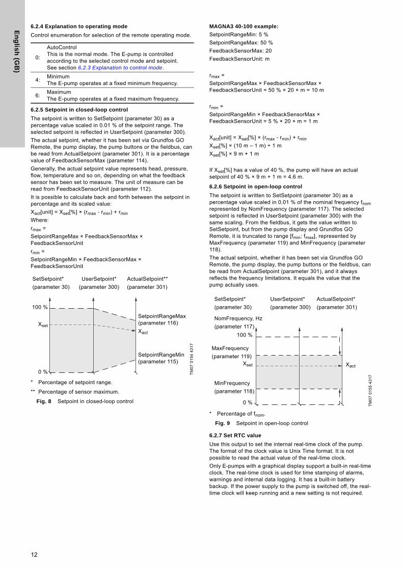
6.2.5 Setpoint in closed-loop control
The setpoint is written to SetSetpoint (parameter 30) as a percentage value scaled in 0.01 % of the setpoint range. The selected setpoint is reflected in UserSetpoint (parameter 300).
The actual setpoint, whether it has been set via Grundfos GO Remote, the pump display, the pump buttons or the fieldbus, can be read from ActualSetpoint (parameter 301). It is a percentage value of FeedbackSensorMax (parameter 114).
Generally, the actual setpoint value represents head, pressure, flow, temperature and so on, depending on what the feedback sensor has been set to measure. The unit of measure can be read from FeedbackSensorUnit (parameter 112).
It is possible to calculate back and forth between the setpoint in percentage and its scaled value:
Xact[unit] = Xset[%] × (rmax - rmin) + rmin
Where:
rmax =
SetpointRangeMax × FeedbackSensorMax × FeedbackSensorUnit
rmin =
SetpointRangeMin × FeedbackSensorMax × FeedbackSensorUnit
* Percentage of setpoint range.
** Percentage of sensor maximum.
Fig. 8 Setpoint in closed-loop control
MAGNA3 40-100 example:
SetpointRangeMin: 5 %
SetpointRangeMax: 50 %
FeedbackSensorMax: 20
FeedbackSensorUnit: m
rmax =
SetpointRangeMax × FeedbackSensorMax × FeedbackSensorUnit = 50 % × 20 × m = 10 m
rmin =
SetpointRangeMin × FeedbackSensorMax × FeedbackSensorUnit = 5 % × 20 × m = 1 m
Xact[unit] = Xset[%] × (rmax - rmin) + rmin
Xset[%] × (10 m – 1 m) + 1 m
Xset[%] × 9 m + 1 m
If Xset[%] has a value of 40 %, the pump will have an actual setpoint of 40 % × 9 m + 1 m = 4.6 m.
6.2.6 Setpoint in open-loop control
The setpoint is written to SetSetpoint (parameter 30) as a percentage value scaled in 0.01 % of the nominal frequency fnom represented by NomFrequency (parameter 117). The selected setpoint is reflected in UserSetpoint (parameter 300) with the same scaling. From the fieldbus, it gets the value written to SetSetpoint, but from the pump display and Grundfos GO Remote, it is truncated to range [fmin; fmax], represented by MaxFrequency (parameter 119) and MinFrequency (parameter 118).
The actual setpoint, whether it has been set via Grundfos GO Remote, the pump display, the pump buttons or the fieldbus, can be read from ActualSetpoint (parameter 301), and it always reflects the frequency limitations. It equals the value that the pump actually uses.
* Percentage of fnom.
Fig. 9 Setpoint in open-loop control
6.2.7 Set RTC value
Use this output to set the internal real-time clock of the pump. The format of the clock value is Unix Time format. It is not possible to read the actual value of the real-time clock.
Only E-pumps with a graphical display support a built-in real-time clock. The real-time clock is used for time stamping of alarms, warnings and internal data logging. It has a built-in battery backup. If the power supply to the pump is switched off, the real-time clock will keep running and a new setting is not required.
0:
AutoControlThis is the normal mode. The E-pump is controlled according to the selected control mode and setpoint. See section 6.2.3 Explanation to control mode.
4:MinimumThe E-pump operates at a fixed minimum frequency.
6:MaximumThe E-pump operates at a fixed maximum frequency.
TM
07
01
54
43
17
Xset
0 %
100 %
Xact
SetpointRangeMax (parameter 116)
SetSetpoint*
(parameter 30)
UserSetpoint*
(parameter 300)
ActualSetpoint**
(parameter 301)
SetpointRangeMin (parameter 115)
TM
07
01
55
43
17
Xset Xact
100 %
MaxFrequency
(parameter 119)
MinFrequency
(parameter 118)
NomFrequency, Hz
(parameter 117)
0 %
SetSetpoint*
(parameter 30)
UserSetpoint*
(parameter 300)
ActualSetpoint*
(parameter 301)
12
En
gli
sh
(G
B)
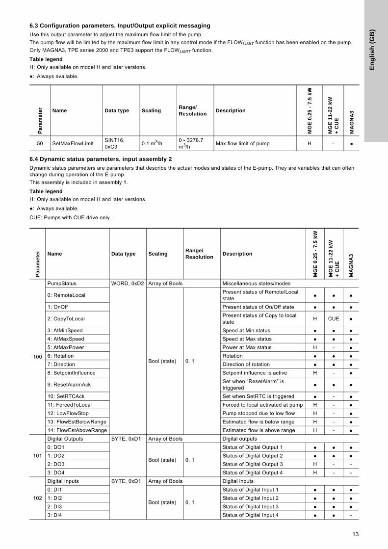
6.3 Configuration parameters, Input/Output explicit messaging
Use this output parameter to adjust the maximum flow limit of the pump.
The pump flow will be limited by the maximum flow limit in any control mode if the FLOWLIMIT function has been enabled on the pump.
Only MAGNA3, TPE series 2000 and TPE3 support the FLOWLIMIT function.
Table legend
H: Only available on model H and later versions.
●: Always available.
6.4 Dynamic status parameters, input assembly 2
Dynamic status parameters are parameters that describe the actual modes and states of the E-pump. They are variables that can often change during operation of the E-pump.
This assembly is included in assembly 1.
Table legend
H: Only available on model H and later versions.
●: Always available.
CUE: Pumps with CUE drive only.
Pa
ram
ete
r Name Data type ScalingRange/Resolution
Description
MG
E 0
.25
- 7
.5 k
W
MG
E 1
1-2
2 k
W
+ C
UE
MA
GN
A3
50 SetMaxFlowLimitSINT16, 0xC3
0.1 m3/h0 - 3276.7 m3/h
Max flow limit of pump H - ●
Pa
ram
ete
r Name Data type ScalingRange/Resolution
Description
MG
E 0
.25
- 7
.5 k
W
MG
E 1
1-2
2 k
W
+ C
UE
MA
GN
A3
100
PumpStatus WORD, 0xD2 Array of Bools Miscellaneous states/modes
0: RemoteLocal
Bool (state) 0, 1
Present status of Remote/Local state ● ● ●
1: OnOff Present status of On/Off state ● ● ●
2: CopyToLocalPresent status of Copy to local state
H CUE ●
3: AtMinSpeed Speed at Min status ● ● ●4: AtMaxSpeed Speed at Max status ● ● ●5: AtMaxPower Power at Max status H - ●6: Rotation Rotation ● ● ●7: Direction Direction of rotation ● ● ●8: SetpointInfluence Setpoint influence is active H - ●
9: ResetAlarmAckSet when “ResetAlarm” is triggered ● ● ●
10: SetRTCAck Set when SetRTC is triggered ● - ●11: ForcedToLocal Forced to local activated at pump H - ●12: LowFlowStop Pump stopped due to low flow H - ●13: FlowEstBelowRange Estimated flow is below range H - ●14: FlowEstAboveRange Estimated flow is above range H - ●
101
Digital Outputs BYTE, 0xD1 Array of Bools Digital outputs
0: DO1
Bool (state) 0, 1
Status of Digital Output 1 ● ● ●1: DO2 Status of Digital Output 2 ● ● ●2: DO3 Status of Digital Output 3 H - -
3: DO4 Status of Digital Output 4 H - -
102
Digital Inputs BYTE, 0xD1 Array of Bools Digital inputs
0: DI1
Bool (state) 0, 1
Status of Digital Input 1 ● ● ●1: DI2 Status of Digital Input 2 ● ● ●2: DI3 Status of Digital Input 3 ● ● ●3: DI4 Status of Digital Input 4 ● ● -
13
En
glis
h (G
B)
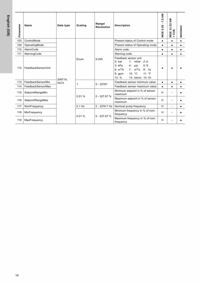
103 ControlMode
SINT16, 0xC3
Enum 0-255
Present status of Control mode ● ● ●104 OperatingMode Present status of Operating mode ● ● ●110 AlarmCode Alarm code ● ● ●111 WarningCode Warning code ● ● ●
112 FeedbackSensorUnit
Feedback sensor unit0: bar 1: mbar 2:m
3: kPa 4: psi 5: ft.
6: m3/h 7: m3/s 8: l/s
9: gpm 10: °C 11: °F
12: % 13: kelvin 14: l/h
● ● ●
113 FeedbackSensorMin1 0 - 32767
Feedback sensor minimum value ● ● ●114 FeedbackSensorMax Feedback sensor maximum value ● ● ●
115 SetpointRangeMin
0.01 % 0 - 327.67 %
Minimum setpoint in % of sensor maximum
H - ●
116 SetpointRangeMaxMaximum setpoint in % of sensor maximum
H - ●
117 NomFrequency 0.1 Hz 0 - 3276.7 Hz Nominal pump frequency H - ●
118 MinFrequency
0.01 % 0 - 327.67 %
Minimum frequency in % of nom. frequency
H - ●
119 MaxFrequencyMaximum frequency in % of nom. frequency
H - ●
Pa
ram
ete
r Name Data type ScalingRange/Resolution
Description
MG
E 0
.25
- 7
.5 k
W
MG
E 1
1-2
2 k
W
+ C
UE
MA
GN
A3
14
En
gli
sh
(G
B)
6.4.1 Explanation to the dynamic status parameters
RemoteLocal
Status bit indicating whether the E-pump is controlled from the bus or from some other control source.
To allow the E-pump to be controlled from the bus, the SetRemoteLocal control bit must be set to "1". However, certain commands from other control sources, for example Stop or Max. from a local source or external Stop from a digital input, have a higher priority. If active RemoteLocal bit reads "0", it indicates that the actual control source is not the bus.
OnOff
Status bit indicating whether the E-pump is started or stopped.
The E-pump can be started and stopped from the bus by using the OnOff control bit SetOnOff.
"Started" does not necessarily indicate that the E-pump is pumping as it might be in a "low-flow stop" condition.
CopyToLocal
Indicates if the remote settings of setpoint operating mode, control mode and OnOff state must be automatically copied to local settings.
AtMinSpeed
Status bit indicating that the E-pump is running at minimum speed.
AtMaxSpeed
Status bit indicating that the E-pump is running at maximum speed.
Only available on MAGNA3 and MGE model H and later.
AtMaxPower
Status bit indicating that the E-pump is running at maximum power limit.
Only available on MAGNA3 and MGE model H and later.
Rotation
Status bit indicating that the motor is rotating (consuming power).
Direction
Status bit indicating the direction of rotation of the E-pump as seen from ventilator side.
SetPointInfluence
Status bit indicating if the setpoint is influenced, for example by analog input or by temperature. If influenced, the ActualSetpoint (parameter 301) will differ from the UserSetpoint (parameter 300).
Only available on MAGNA3 and MGE model H and later.
ResetAlarmAck
Acknowledge bit belonging to the ResetAlarm control bit. It will be set when the control bit is set and the command has been executed. It will be cleared when the control bit is cleared.
SetRTCAck
Acknowledge bit belonging to the SetRTCValue. It is set when the real-time clock is updated.
ForcedToLocal
Status bit indicating that the E-pump has been "Forced to local mode" from display or from Grundfos GO Remote.
Only available on MAGNA3 and MGE model H and later.
LowFlowStop
Status bit indicating that the E-pump has stopped due to low flow.
Only available on MAGNA3 and MGE model H and later.
FlowEstimateBelowRange
The flow estimation is below its normal minimum range and a higher inaccuracy can be expected.
Only available on MAGNA3 and MGE model H and later.
FlowEstimateAboveRange
The flow estimation is above its normal maximum range and a higher inaccuracy can be expected.
Only available on MAGNA3 and MGE model H and later.
ControlMode
Status enumeration showing the actual E-pump control mode.
See section 6.2.3 Explanation to control mode for detailed explanation to the various control modes.
OperatingMode
Status enumeration showing the actual E-pump operating mode.
See section 6.2.4 Explanation to operating mode for detailed explanation to the various operating modes.
0:The E-pump is controlled from a local source, buttons or Grundfos GO Remote or from an external digital input
1: The E-pump is controlled from EtherNet/IP, remotely
0: The E-pump is stopped
1: The E-pump is started
0: Copying disabled
1: Copying enabled
0: The E-pump is not running at minimum speed
1: The E-pump is running at minimum speed
0: The E-pump is not running at maximum speed
1: The E-pump is running at maximum speed
0: The E-pump is not running at maximum power limit
1: The E-pump is running at maximum power limit
0: No rotation
1: Rotation
0: Clockwise (CW)
1: Counterclockwise (CCW)
0: No setpoint influence
1: The setpoint is influenced
0: The E-pump has not been "forced to local"
1: The E-pump has been "forced to local"
0: Low Flow Stop not activated
1: Low Flow Stop activated
0: The flow estimation is not below its normal range
1: The flow estimation is below its normal range
0: The flow estimation is not above its normal range
1: The flow estimation is above its normal range
15
En
glis
h (G
B)
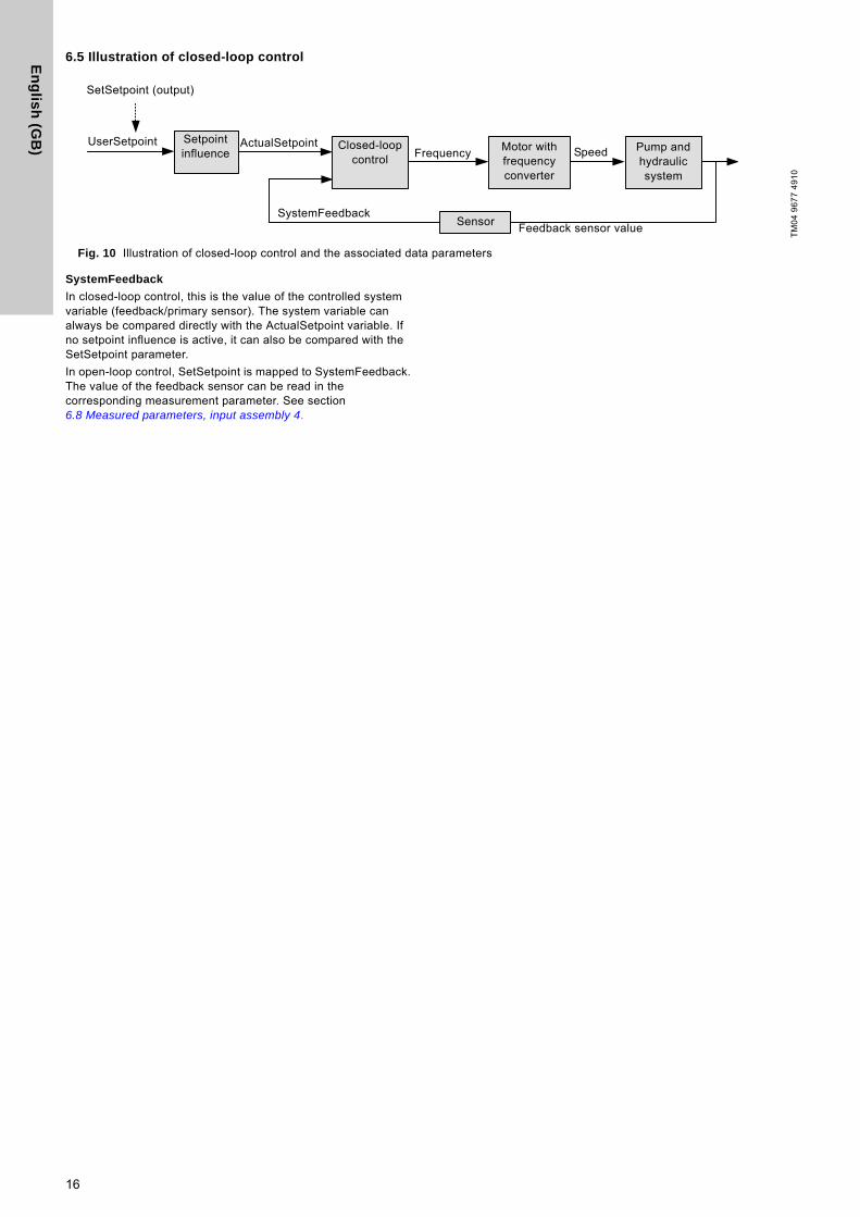
6.5 Illustration of closed-loop control
Fig. 10 Illustration of closed-loop control and the associated data parameters
SystemFeedback
In closed-loop control, this is the value of the controlled system variable (feedback/primary sensor). The system variable can always be compared directly with the ActualSetpoint variable. If no setpoint influence is active, it can also be compared with the SetSetpoint parameter.
In open-loop control, SetSetpoint is mapped to SystemFeedback. The value of the feedback sensor can be read in the corresponding measurement parameter. See section 6.8 Measured parameters, input assembly 4.
TM
04
96
77
49
10
SetSetpoint (output)
UserSetpoint Setpoint influence
ActualSetpoint Closed-loop control
Motor with frequency converter
Pump and hydraulic system
Sensor
Frequency Speed
SystemFeedbackFeedback sensor value
16
En
gli
sh
(G
B)
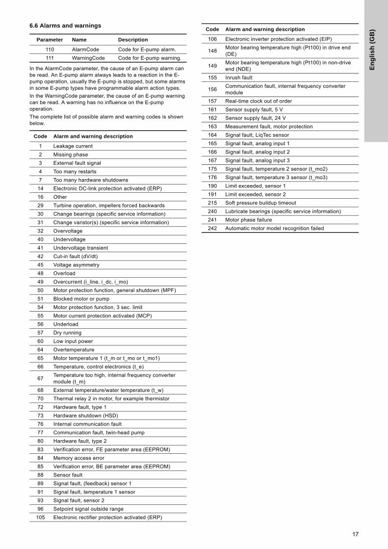
6.6 Alarms and warnings
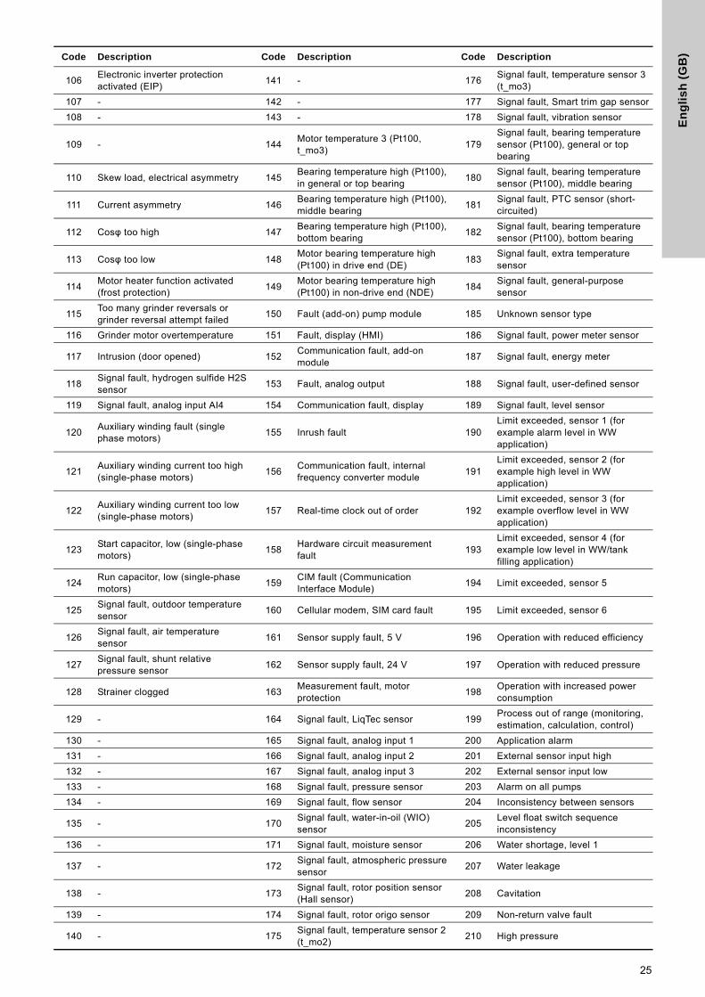
In the AlarmCode parameter, the cause of an E-pump alarm can be read. An E-pump alarm always leads to a reaction in the E-pump operation, usually the E-pump is stopped, but some alarms in some E-pump types have programmable alarm action types.
In the WarningCode parameter, the cause of an E-pump warning can be read. A warning has no influence on the E-pump operation.
The complete list of possible alarm and warning codes is shown below.
Parameter Name Description
110 AlarmCode Code for E-pump alarm.
111 WarningCode Code for E-pump warning.
Code Alarm and warning description
1 Leakage current
2 Missing phase
3 External fault signal
4 Too many restarts
7 Too many hardware shutdowns
14 Electronic DC-link protection activated (ERP)
16 Other
29 Turbine operation, impellers forced backwards
30 Change bearings (specific service information)
31 Change varistor(s) (specific service information)
32 Overvoltage
40 Undervoltage
41 Undervoltage transient
42 Cut-in fault (dV/dt)
45 Voltage asymmetry
48 Overload
49 Overcurrent (i_line, i_dc, i_mo)
50 Motor protection function, general shutdown (MPF)
51 Blocked motor or pump
54 Motor protection function, 3 sec. limit
55 Motor current protection activated (MCP)
56 Underload
57 Dry running
60 Low input power
64 Overtemperature
65 Motor temperature 1 (t_m or t_mo or t_mo1)
66 Temperature, control electronics (t_e)
67Temperature too high, internal frequency converter module (t_m)
68 External temperature/water temperature (t_w)
70 Thermal relay 2 in motor, for example thermistor
72 Hardware fault, type 1
73 Hardware shutdown (HSD)
76 Internal communication fault
77 Communication fault, twin-head pump
80 Hardware fault, type 2
83 Verification error, FE parameter area (EEPROM)
84 Memory access error
85 Verification error, BE parameter area (EEPROM)
88 Sensor fault
89 Signal fault, (feedback) sensor 1
91 Signal fault, temperature 1 sensor
93 Signal fault, sensor 2
96 Setpoint signal outside range
105 Electronic rectifier protection activated (ERP)
106 Electronic inverter protection activated (EIP)
148Motor bearing temperature high (Pt100) in drive end (DE)
149Motor bearing temperature high (Pt100) in non-drive end (NDE)
155 Inrush fault
156Communication fault, internal frequency converter module
157 Real-time clock out of order
161 Sensor supply fault, 5 V
162 Sensor supply fault, 24 V
163 Measurement fault, motor protection
164 Signal fault, LiqTec sensor
165 Signal fault, analog input 1
166 Signal fault, analog input 2
167 Signal fault, analog input 3
175 Signal fault, temperature 2 sensor (t_mo2)
176 Signal fault, temperature 3 sensor (t_mo3)
190 Limit exceeded, sensor 1
191 Limit exceeded, sensor 2
215 Soft pressure buildup timeout
240 Lubricate bearings (specific service information)
241 Motor phase failure
242 Automatic motor model recognition failed
Code Alarm and warning description
17
En
glis
h (G
B)
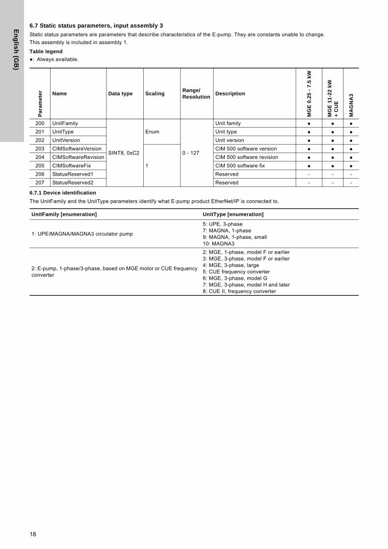
6.7 Static status parameters, input assembly 3
Static status parameters are parameters that describe characteristics of the E-pump. They are constants unable to change.
This assembly is included in assembly 1.
Table legend
●: Always available.
6.7.1 Device identification
The UnitFamily and the UnitType parameters identify what E-pump product EtherNet/IP is connected to.
Pa
ram
ete
r Name Data type ScalingRange/Resolution
Description
MG
E 0
.25
- 7
.5 k
W
MG
E 1
1-2
2 k
W
+ C
UE
MA
GN
A3
200 UnitFamily
SINT8, 0xC2
Enum
0 - 127
Unit family ● ● ●201 UnitType Unit type ● ● ●202 UnitVersion Unit version ● ● ●203 CIMSoftwareVersion
1
CIM 500 software version ● ● ●204 CIMSoftwareRevision CIM 500 software revision ● ● ●205 CIMSoftwareFix CIM 500 software fix ● ● ●206 StatusReserved1 Reserved - - -
207 StatusReserved2 Reserved - - -
UnitFamily [enumeration] UnitType [enumeration]
1: UPE/MAGNA/MAGNA3 circulator pump
5: UPE, 3-phase7: MAGNA, 1-phase9: MAGNA, 1-phase, small10: MAGNA3
2: E-pump, 1-phase/3-phase, based on MGE motor or CUE frequency converter
2: MGE, 1-phase, model F or earlier3: MGE, 3-phase, model F or earlier4: MGE, 3-phase, large5: CUE frequency converter6: MGE, 3-phase, model G7: MGE, 3-phase, model H and later8: CUE II, frequency converter
18
En
gli
sh
(G
B)
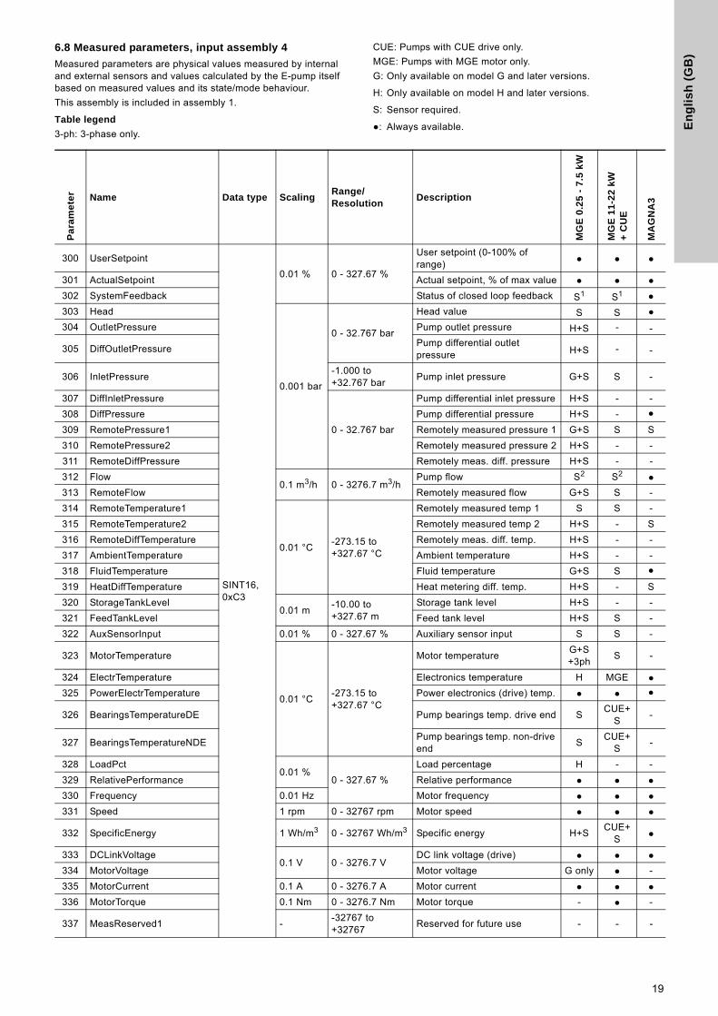
6.8 Measured parameters, input assembly 4
Measured parameters are physical values measured by internal and external sensors and values calculated by the E-pump itself based on measured values and its state/mode behaviour.
This assembly is included in assembly 1.
Table legend
3-ph: 3-phase only.
CUE: Pumps with CUE drive only.
MGE: Pumps with MGE motor only.
G: Only available on model G and later versions.
H: Only available on model H and later versions.
S: Sensor required.
●: Always available.
Pa
ram
ete
r Name Data type ScalingRange/Resolution
Description
MG
E 0
.25
- 7
.5 k
W
MG
E 1
1-2
2 k
W
+ C
UE
MA
GN
A3
300 UserSetpoint
SINT16, 0xC3
0.01 % 0 - 327.67 %
User setpoint (0-100% of range) ● ● ●
301 ActualSetpoint Actual setpoint, % of max value ● ● ●302 SystemFeedback Status of closed loop feedback S1 S1 ●303 Head
0.001 bar
0 - 32.767 bar
Head value S S ●304 OutletPressure Pump outlet pressure H+S - -
305 DiffOutletPressurePump differential outlet pressure H+S - -
306 InletPressure-1.000 to +32.767 bar
Pump inlet pressure G+S S -
307 DiffInletPressure
0 - 32.767 bar
Pump differential inlet pressure H+S - -
308 DiffPressure Pump differential pressure H+S - ●309 RemotePressure1 Remotely measured pressure 1 G+S S S
310 RemotePressure2 Remotely measured pressure 2 H+S - -
311 RemoteDiffPressure Remotely meas. diff. pressure H+S - -
312 Flow0.1 m3/h 0 - 3276.7 m3/h
Pump flow S2 S2 ●313 RemoteFlow Remotely measured flow G+S S -
314 RemoteTemperature1
0.01 °C-273.15 to +327.67 °C
Remotely measured temp 1 S S -
315 RemoteTemperature2 Remotely measured temp 2 H+S - S
316 RemoteDiffTemperature Remotely meas. diff. temp. H+S - -
317 AmbientTemperature Ambient temperature H+S - -
318 FluidTemperature Fluid temperature G+S S ●319 HeatDiffTemperature Heat metering diff. temp. H+S - S
320 StorageTankLevel0.01 m
-10.00 to +327.67 m
Storage tank level H+S - -
321 FeedTankLevel Feed tank level H+S S -
322 AuxSensorInput 0.01 % 0 - 327.67 % Auxiliary sensor input S S -
323 MotorTemperature
0.01 °C-273.15 to +327.67 °C
Motor temperatureG+S+3ph
S -
324 ElectrTemperature Electronics temperature H MGE ●325 PowerElectrTemperature Power electronics (drive) temp. ● ● ●
326 BearingsTemperatureDE Pump bearings temp. drive end SCUE+
S-
327 BearingsTemperatureNDEPump bearings temp. non-drive end
SCUE+
S-
328 LoadPct0.01 %
0 - 327.67 %
Load percentage H - -
329 RelativePerformance Relative performance ● ● ●330 Frequency 0.01 Hz Motor frequency ● ● ●331 Speed 1 rpm 0 - 32767 rpm Motor speed ● ● ●
332 SpecificEnergy 1 Wh/m3 0 - 32767 Wh/m3 Specific energy H+SCUE+
S ●
333 DCLinkVoltage0.1 V 0 - 3276.7 V
DC link voltage (drive) ● ● ●334 MotorVoltage Motor voltage G only ● -
335 MotorCurrent 0.1 A 0 - 3276.7 A Motor current ● ● ●336 MotorTorque 0.1 Nm 0 - 3276.7 Nm Motor torque - ● -
337 MeasReserved1 --32767 to +32767
Reserved for future use - - -
19
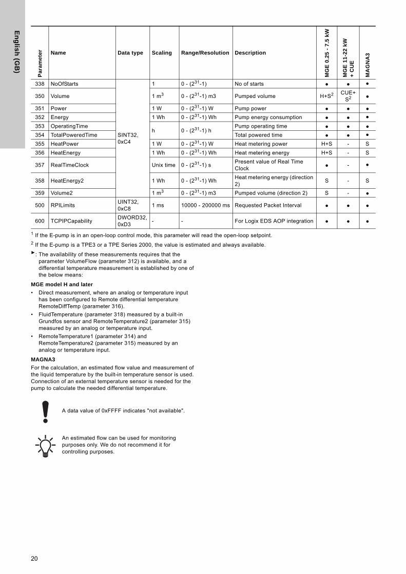
En
glis
h (G
B)
1 If the E-pump is in an open-loop control mode, this parameter will read the open-loop setpoint.2 If the E-pump is a TPE3 or a TPE Series 2000, the value is estimated and always available.►: The availability of these measurements requires that the
parameter VolumeFlow (parameter 312) is available, and a differential temperature measurement is established by one of the below means:
MGE model H and later
• Direct measurement, where an analog or temperature input has been configured to Remote differential temperature RemoteDiffTemp (parameter 316).
• FluidTemperature (parameter 318) measured by a built-in Grundfos sensor and RemoteTemperature2 (parameter 315) measured by an analog or temperature input.
• RemoteTemperature1 (parameter 314) and RemoteTemperature2 (parameter 315) measured by an analog or temperature input.
MAGNA3
For the calculation, an estimated flow value and measurement of the liquid temperature by the built-in temperature sensor is used. Connection of an external temperature sensor is needed for the pump to calculate the needed differential temperature.
Pa
ram
ete
r Name Data type Scaling Range/Resolution Description
MG
E 0
.25
- 7
.5 k
W
MG
E 1
1-2
2 k
W
+ C
UE
MA
GN
A3
338 NoOfStarts
SINT32, 0xC4
1 0 - (231-1) No of starts ● ● ●
350 Volume 1 m3 0 - (231-1) m3 Pumped volume H+S2 CUE+S2 ●
351 Power 1 W 0 - (231-1) W Pump power ● ● ●352 Energy 1 Wh 0 - (231-1) Wh Pump energy consumption ● ● ●353 OperatingTime
h 0 - (231-1) hPump operating time ● ● ●
354 TotalPoweredTime Total powered time ● ● ●355 HeatPower 1 W 0 - (231-1) W Heat metering power H+S - S
356 HeatEnergy 1 Wh 0 - (231-1) Wh Heat metering energy H+S - S
357 RealTimeClock Unix time 0 - (231-1) sPresent value of Real Time Clock ● - ●
358 HeatEnergy2 1 Wh 0 - (231-1) WhHeat metering energy (direction 2)
S - S
359 Volume2 1 m3 0 - (231-1) m3 Pumped volume (direction 2) S - ●
500 RPILimitsUINT32, 0xC8
1 ms 10000 - 200000 ms Requested Packet Interval ● ● ●
600 TCPIPCapabilityDWORD32, 0xD3
- - For Logix EDS AOP integration ● ● ●
A data value of 0xFFFF indicates "not available".
An estimated flow can be used for monitoring purposes only. We do not recommend it for controlling purposes.
20
En
gli
sh
(G
B)
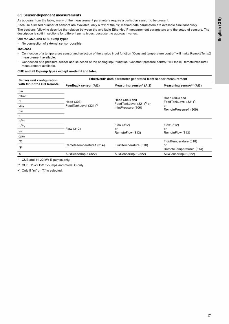
6.9 Sensor-dependent measurements
As appears from the table, many of the measurement parameters require a particular sensor to be present.
Because a limited number of sensors are available, only a few of the "S" marked data parameters are available simultaneously.
The sections following describe the relation between the available EtherNet/IP measurement parameters and the setup of sensors. The description is split in sections for different pump types, because the approach varies.
Old MAGNA and UPE pump types
• No connection of external sensor possible.
MAGNA3
• Connection of a temperature sensor and selection of the analog input function "Constant temperature control" will make RemoteTemp2 measurement available.
• Connection of a pressure sensor and selection of the analog input function "Constant pressure control" will make RemotePressure1 measurement available.
CUE and all E-pump types except model H and later.
* CUE and 11-22 kW E-pumps only.
** CUE, 11-22 kW E-pumps and model G only.
+) Only if "m" or "ft" is selected.
Sensor unit configuration with Grundfos GO Remote
EtherNet/IP data parameter generated from sensor measurement
Feedback sensor (AI1) Measuring sensor* (AI2) Measuring sensor** (AI3)
bar
Head (303)FeedTankLevel (321)+)
Head (303) andFeedTankLevel (321)+) or InletPressure (306)
Head (303) andFeedTankLevel (321)+)
or RemotePressure1 (309)
mbar
m
kPa
psi
ft
m3/h
Flow (312)Flow (312)or RemoteFlow (313)
Flow (312)or RemoteFlow (313)
m3/s
l/s
gpm
°CRemoteTemperature1 (314) FluidTemperature (318)
FluidTemperature (318)orRemoteTemperature1 (314)°F
% AuxSensorInput (322) AuxSensorInput (322) AuxSensorInput (322)
21
En
glis
h (G
B)
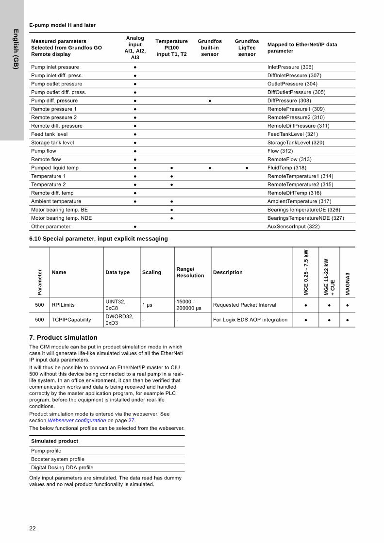
E-pump model H and later
6.10 Special parameter, input explicit messaging
7. Product simulationThe CIM module can be put in product simulation mode in which case it will generate life-like simulated values of all the EtherNet/IP input data parameters.
It will thus be possible to connect an EtherNet/IP master to CIU 500 without this device being connected to a real pump in a real-life system. In an office environment, it can then be verified that communication works and data is being received and handled correctly by the master application program, for example PLC program, before the equipment is installed under real-life conditions.
Product simulation mode is entered via the webserver. See section Webserver configuration on page 27.
The below functional profiles can be selected from the webserver.
Only input parameters are simulated. The data read has dummy values and no real product functionality is simulated.
Measured parametersSelected from Grundfos GO Remote display
Analog input
AI1, AI2, AI3
Temperature Pt100
input T1, T2
Grundfos built-in sensor
Grundfos LiqTec sensor
Mapped to EtherNet/IP data parameter
Pump inlet pressure ● InletPressure (306)
Pump inlet diff. press. ● DiffInletPressure (307)
Pump outlet pressure ● OutletPressure (304)
Pump outlet diff. press. ● DiffOutletPressure (305)
Pump diff. pressure ● ● DiffPressure (308)
Remote pressure 1 ● RemotePressure1 (309)
Remote pressure 2 ● RemotePressure2 (310)
Remote diff. pressure ● RemoteDiffPressure (311)
Feed tank level ● FeedTankLevel (321)
Storage tank level ● StorageTankLevel (320)
Pump flow ● Flow (312)
Remote flow ● RemoteFlow (313)
Pumped liquid temp ● ● ● ● FluidTemp (318)
Temperature 1 ● ● RemoteTemperature1 (314)
Temperature 2 ● ● RemoteTemperature2 (315)
Remote diff. temp ● RemoteDiffTemp (316)
Ambient temperature ● ● AmbientTemperature (317)
Motor bearing temp. BE ● BearingsTemperatureDE (326)
Motor bearing temp. NDE ● BearingsTemperatureNDE (327)
Other parameter ● AuxSensorInput (322)
Pa
ram
ete
r Name Data type ScalingRange/Resolution
Description
MG
E 0
.25
- 7
.5 k
W
MG
E 1
1-2
2 k
W
+ C
UE
MA
GN
A3
500 RPILimitsUINT32, 0xC8
1 μs15000 - 200000 μs
Requested Packet Interval ● ● ●
500 TCPIPCapabilityDWORD32, 0xD3
- - For Logix EDS AOP integration ● ● ●
Simulated product
Pump profile
Booster system profile
Digital Dosing DDA profile
22
En
gli
sh
(G
B)
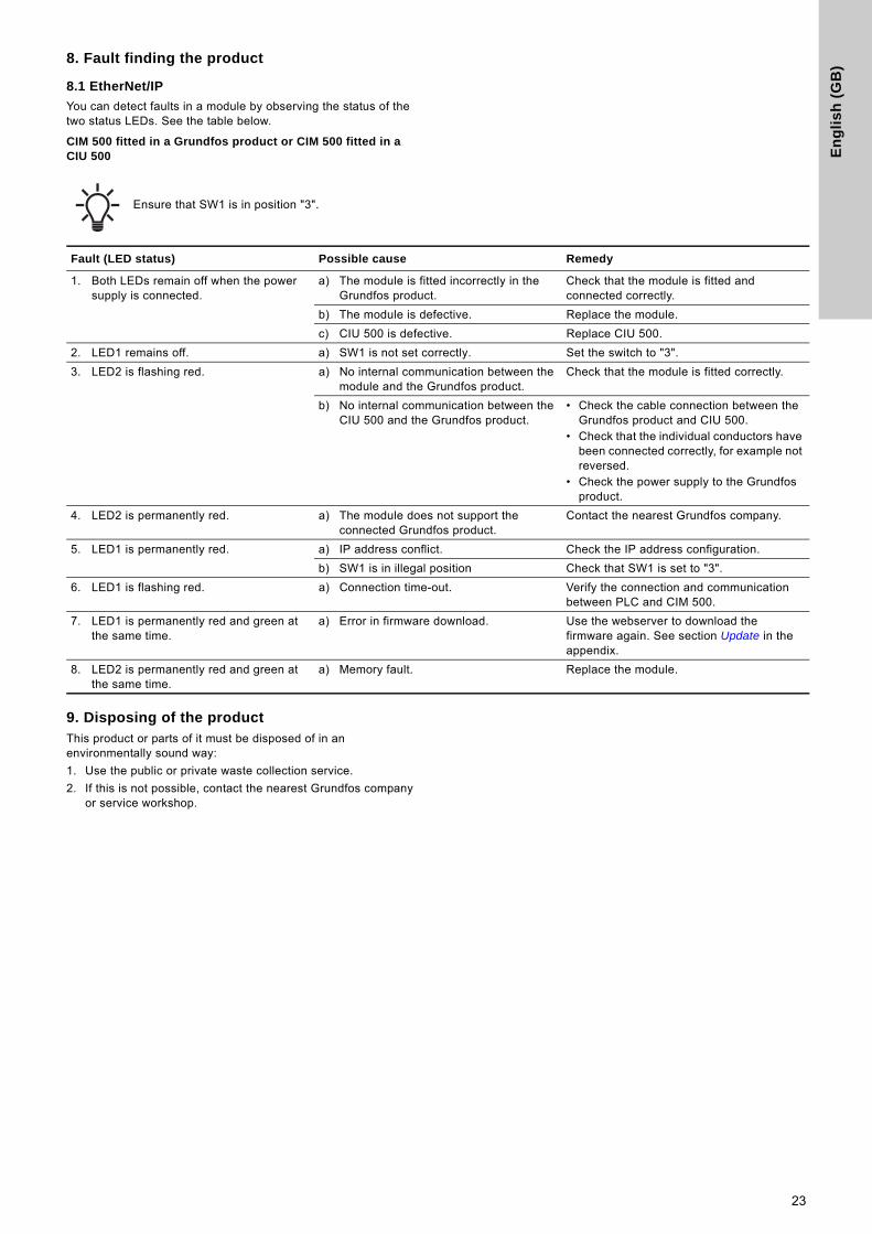
8. Fault finding the product8.1 EtherNet/IP
You can detect faults in a module by observing the status of the two status LEDs. See the table below.
CIM 500 fitted in a Grundfos product or CIM 500 fitted in a CIU 500
9. Disposing of the productThis product or parts of it must be disposed of in an environmentally sound way:
1. Use the public or private waste collection service.
2. If this is not possible, contact the nearest Grundfos company or service workshop.
Ensure that SW1 is in position "3".
Fault (LED status) Possible cause Remedy
1. Both LEDs remain off when the power supply is connected.
a) The module is fitted incorrectly in the Grundfos product.
Check that the module is fitted and connected correctly.
b) The module is defective. Replace the module.
c) CIU 500 is defective. Replace CIU 500.
2. LED1 remains off. a) SW1 is not set correctly. Set the switch to "3".
3. LED2 is flashing red. a) No internal communication between the module and the Grundfos product.
Check that the module is fitted correctly.
b) No internal communication between the CIU 500 and the Grundfos product.
• Check the cable connection between the Grundfos product and CIU 500.
• Check that the individual conductors have been connected correctly, for example not reversed.
• Check the power supply to the Grundfos product.
4. LED2 is permanently red. a) The module does not support the connected Grundfos product.
Contact the nearest Grundfos company.
5. LED1 is permanently red. a) IP address conflict. Check the IP address configuration.
b) SW1 is in illegal position Check that SW1 is set to "3".
6. LED1 is flashing red. a) Connection time-out. Verify the connection and communication between PLC and CIM 500.
7. LED1 is permanently red and green at the same time.
a) Error in firmware download. Use the webserver to download the firmware again. See section Update in the appendix.
8. LED2 is permanently red and green at the same time.
a) Memory fault. Replace the module.
23
En
glis
h (G
B)
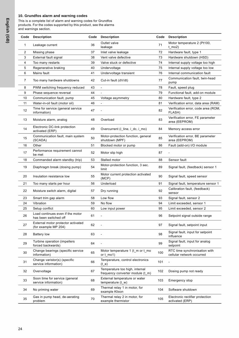
10. Grundfos alarm and warning codesThis is a complete list of alarm and warning codes for Grundfos products. For the codes supported by this product, see the alarms and warnings section.
Code Description Code Description Code Description
1 Leakage current 36Outlet valveleakage
71Motor temperature 2 (Pt100,t_mo2)
2 Missing phase 37 Inlet valve leakage 72 Hardware fault, type 1
3 External fault signal 38 Vent valve defective 73 Hardware shutdown (HSD)
4 Too many restarts 39 Valve stuck or defective 74 Internal supply voltage too high
5 Regenerative braking 40 Undervoltage 75 Internal supply voltage too low
6 Mains fault 41 Undervoltage transient 76 Internal communication fault
7 Too many hardware shutdowns 42 Cut-in fault (dV/dt) 77Communication fault, twin-headpump
8 PWM switching frequency reduced 43 - 78 Fault, speed plug
9 Phase sequence reversal 44 - 79 Functional fault, add-on module
10 Communication fault, pump 45 Voltage asymmetry 80 Hardware fault, type 2
11 Water-in-oil fault (motor oil) 46 - 81 Verification error, data area (RAM)
12Time for service (general serviceinformation)
47 - 82Verification error, code area (ROM,FLASH)
13 Moisture alarm, analog 48 Overload 83Verification error, FE parameterarea (EEPROM)
14Electronic DC-link protectionactivated (ERP)
49 Overcurrent (i_line, i_dc, i_mo) 84 Memory access error
15Communication fault, main system(SCADA)
50Motor-protection function, generalshutdown (MPF)
85Verification error, BE parameterarea (EEPROM)
16 Other 51 Blocked motor or pump 86 Fault (add-on) I/O module
17Performance requirement cannotbe met
52 Motor slip high 87 -
18 Commanded alarm standby (trip) 53 Stalled motor 88 Sensor fault
19 Diaphragm break (dosing pump) 54Motor-protection function, 3 sec.limit
89 Signal fault, (feedback) sensor 1
20 Insulation resistance low 55Motor current protection activated(MCP)
90 Signal fault, speed sensor
21 Too many starts per hour 56 Underload 91 Signal fault, temperature sensor 1
22 Moisture switch alarm, digital 57 Dry running 92Calibration fault, (feedback)sensor
23 Smart trim gap alarm 58 Low flow 93 Signal fault, sensor 2
24 Vibration 59 No flow 94 Limit exceeded, sensor 1
25 Setup conflict 60 Low input power 95 Limit exceeded, sensor 2
26Load continues even if the motorhas been switched off
61 - 96 Setpoint signal outside range
27External motor protector activated(for example MP 204)
62 - 97 Signal fault, setpoint input
28 Battery low 63 - 98Signal fault, input for setpointinfluence
29Turbine operation (impellersforced backwards)
64 - 99Signal fault, input for analogsetpoint
30Change bearings (specific serviceinformation)
65Motor temperature 1 (t_m or t_moor t_mo1)
100RTC time synchronisation withcellular network occurred
31Change varistor(s) (specificservice information)
66Temperature, control electronics(t_e)
101 -
32 Overvoltage 67Temperature too high, internalfrequency converter module (t_m)
102 Dosing pump not ready
33Soon time for service (generalservice information)
68External temperature or watertemperature (t_w)
103 Emergency stop
34 No priming water 69Thermal relay 1 in motor, forexample Klixon
104 Software shutdown
35Gas in pump head, de-aeratingproblem
70Thermal relay 2 in motor, forexample thermistor
105Electronic rectifier protectionactivated (ERP)
24
En
gli
sh
(G
B)
Code Description Code Description Code Description106Electronic inverter protectionactivated (EIP)
141 - 176Signal fault, temperature sensor 3(t_mo3)
107 - 142 - 177 Signal fault, Smart trim gap sensor
108 - 143 - 178 Signal fault, vibration sensor
109 - 144Motor temperature 3 (Pt100,t_mo3)
179Signal fault, bearing temperaturesensor (Pt100), general or topbearing
110 Skew load, electrical asymmetry 145Bearing temperature high (Pt100),in general or top bearing
180Signal fault, bearing temperaturesensor (Pt100), middle bearing
111 Current asymmetry 146Bearing temperature high (Pt100),middle bearing
181Signal fault, PTC sensor (short-circuited)
112 Cosφ too high 147Bearing temperature high (Pt100),bottom bearing
182Signal fault, bearing temperaturesensor (Pt100), bottom bearing
113 Cosφ too low 148Motor bearing temperature high(Pt100) in drive end (DE)
183Signal fault, extra temperaturesensor
114Motor heater function activated(frost protection)
149Motor bearing temperature high(Pt100) in non-drive end (NDE)
184Signal fault, general-purposesensor
115Too many grinder reversals orgrinder reversal attempt failed
150 Fault (add-on) pump module 185 Unknown sensor type
116 Grinder motor overtemperature 151 Fault, display (HMI) 186 Signal fault, power meter sensor
117 Intrusion (door opened) 152Communication fault, add-onmodule
187 Signal fault, energy meter
118Signal fault, hydrogen sulfide H2Ssensor
153 Fault, analog output 188 Signal fault, user-defined sensor
119 Signal fault, analog input AI4 154 Communication fault, display 189 Signal fault, level sensor
120Auxiliary winding fault (singlephase motors)
155 Inrush fault 190Limit exceeded, sensor 1 (forexample alarm level in WWapplication)
121Auxiliary winding current too high(single-phase motors)
156Communication fault, internalfrequency converter module
191Limit exceeded, sensor 2 (forexample high level in WWapplication)
122Auxiliary winding current too low(single-phase motors)
157 Real-time clock out of order 192Limit exceeded, sensor 3 (forexample overflow level in WWapplication)
123Start capacitor, low (single-phasemotors)
158Hardware circuit measurementfault
193Limit exceeded, sensor 4 (forexample low level in WW/tankfilling application)
124Run capacitor, low (single-phasemotors)
159CIM fault (CommunicationInterface Module)
194 Limit exceeded, sensor 5
125Signal fault, outdoor temperaturesensor
160 Cellular modem, SIM card fault 195 Limit exceeded, sensor 6
126Signal fault, air temperaturesensor
161 Sensor supply fault, 5 V 196 Operation with reduced efficiency
127Signal fault, shunt relativepressure sensor
162 Sensor supply fault, 24 V 197 Operation with reduced pressure
128 Strainer clogged 163Measurement fault, motorprotection
198Operation with increased powerconsumption
129 - 164 Signal fault, LiqTec sensor 199Process out of range (monitoring, estimation, calculation, control)
130 - 165 Signal fault, analog input 1 200 Application alarm
131 - 166 Signal fault, analog input 2 201 External sensor input high
132 - 167 Signal fault, analog input 3 202 External sensor input low
133 - 168 Signal fault, pressure sensor 203 Alarm on all pumps
134 - 169 Signal fault, flow sensor 204 Inconsistency between sensors
135 - 170Signal fault, water-in-oil (WIO)sensor
205Level float switch sequenceinconsistency
136 - 171 Signal fault, moisture sensor 206 Water shortage, level 1
137 - 172Signal fault, atmospheric pressuresensor
207 Water leakage
138 - 173Signal fault, rotor position sensor(Hall sensor)
208 Cavitation
139 - 174 Signal fault, rotor origo sensor 209 Non-return valve fault
140 - 175Signal fault, temperature sensor 2(t_mo2)
210 High pressure
25
En
glis
h (G
B)
Code Description Code Description Code Description
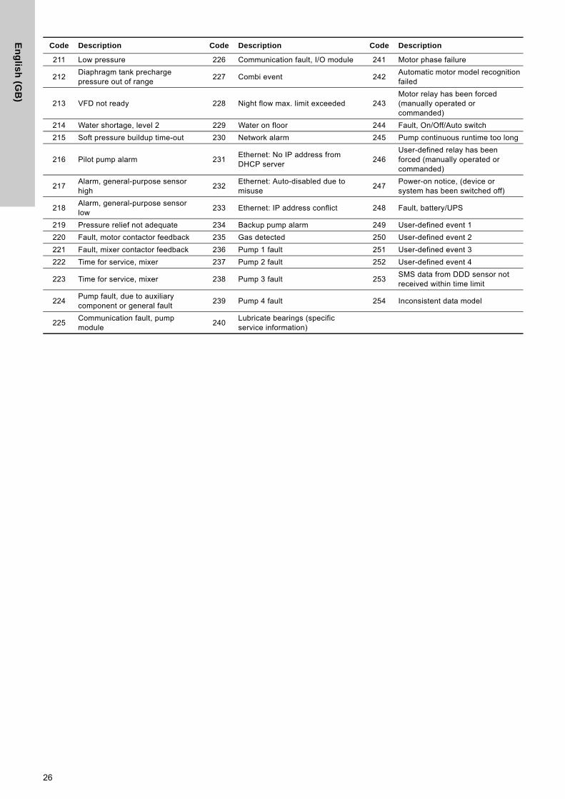
211 Low pressure 226 Communication fault, I/O module 241 Motor phase failure
212Diaphragm tank prechargepressure out of range
227 Combi event 242Automatic motor model recognitionfailed
213 VFD not ready 228 Night flow max. limit exceeded 243Motor relay has been forced(manually operated or commanded)
214 Water shortage, level 2 229 Water on floor 244 Fault, On/Off/Auto switch
215 Soft pressure buildup time-out 230 Network alarm 245 Pump continuous runtime too long
216 Pilot pump alarm 231Ethernet: No IP address fromDHCP server
246User-defined relay has beenforced (manually operated or commanded)
217Alarm, general-purpose sensorhigh
232Ethernet: Auto-disabled due tomisuse
247Power-on notice, (device or system has been switched off)
218Alarm, general-purpose sensorlow
233 Ethernet: IP address conflict 248 Fault, battery/UPS
219 Pressure relief not adequate 234 Backup pump alarm 249 User-defined event 1
220 Fault, motor contactor feedback 235 Gas detected 250 User-defined event 2
221 Fault, mixer contactor feedback 236 Pump 1 fault 251 User-defined event 3
222 Time for service, mixer 237 Pump 2 fault 252 User-defined event 4
223 Time for service, mixer 238 Pump 3 fault 253SMS data from DDD sensor not received within time limit
224Pump fault, due to auxiliarycomponent or general fault
239 Pump 4 fault 254 Inconsistent data model
225Communication fault, pumpmodule
240Lubricate bearings (specificservice information)
26
Ap
pe
nd
ix
Appendix 1
1. Webserver configurationThe built-in webserver offers easy monitoring of the CIM 500 module, and makes it possible to configure the selected Industrial Ethernet protocol. Using the webserver, you can also update the firmware of the CIM 500 module and store or restore settings, among other functions.
To connect a PC to CIM 500, proceed as follows:
1. Connect the PC and the module using an Ethernet cable.
2. Configure the Ethernet port of the PC to the same subnetwork as CIM 500, for example 192.168.1.101. See section How to configure an IP address on your PC using Windows 7 or 1.2 How to configure an IP address on your PC using Windows 10.
3. Open a standard Internet browser and type 192.168.1.100 in the URL field.
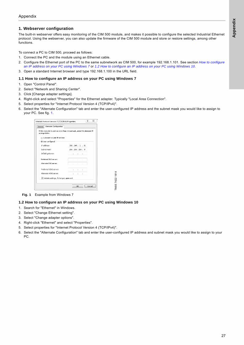
1.1 How to configure an IP address on your PC using Windows 7
1. Open "Control Panel".
2. Select "Network and Sharing Center".
3. Click [Change adapter settings].
4. Right-click and select "Properties" for the Ethernet adapter. Typically "Local Area Connection".
5. Select properties for "Internet Protocol Version 4 (TCP/IPv4)".
6. Select the "Alternate Configuration" tab and enter the user-configured IP address and the subnet mask you would like to assign to your PC. See fig. 1.
Fig. 1 Example from Windows 7
1.2 How to configure an IP address on your PC using Windows 10
1. Search for "Ethernet" in Windows.
2. Select "Change Ethernet setting".
3. Select "Change adapter options".
4. Right-click "Ethernet" and select "Properties".
5. Select properties for "Internet Protocol Version 4 (TCP/IPv4)".
6. Select the "Alternate Configuration" tab and enter the user-configured IP address and subnet mask you would like to assign to your PC.
TM
05
74
22
18
14
27
Ap
pe
nd
ix
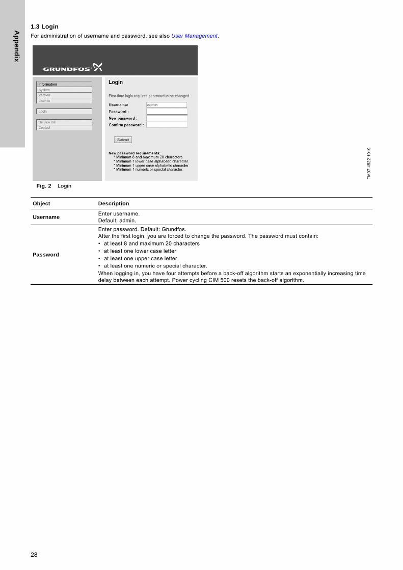
1.3 Login
For administration of username and password, see also User Management.
Fig. 2 Login
TM
07
45
22
19
19
Object Description
UsernameEnter username. Default: admin.
Password
Enter password. Default: Grundfos. After the first login, you are forced to change the password. The password must contain:• at least 8 and maximum 20 characters• at least one lower case letter• at least one upper case letter• at least one numeric or special character. When logging in, you have four attempts before a back-off algorithm starts an exponentially increasing time delay between each attempt. Power cycling CIM 500 resets the back-off algorithm.
28
Ap
pe
nd
ix
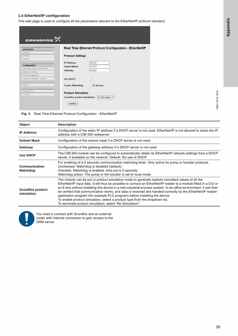
1.4 EtherNet/IP configuration
This web page is used to configure all the parameters relevant to the EtherNet/IP protocol standard.
Fig. 3 Real Time Ethernet Protocol Configuration - EtherNet/IP
TM
07
45
19
19
19
Object Description
IP AddressConfiguration of the static IP address if a DHCP server is not used. EtherNet/IP is not allowed to share the IP address with a CIM 500 webserver.
Subnet Mask Configuration of the subnet mask if a DHCP server is not used.
Gateway Configuration of the gateway address if a DHCP server is not used.
Use DHCPThe CIM 500 module can be configured to automatically obtain its EtherNet/IP network settings from a DHCP server, if available on the network. Default: No use of DHCP.
Communication Watchdog
For enabling of a 5 seconds communication watchdog timer. Only active for pump or booster products.Unchecked: Watchdog is disabled (default).Checked: Watchdog is enabled, time-out is 5 seconds.Watchdog action: The pump or the booster is set to local mode.
Grundfos product simulation
The module can be put in product simulation mode to generate realistic simulated values of all the EtherNet/IP input data. It will thus be possible to connect an EtherNet/IP master to a module fitted in a CIU or an E-box without installing this device in a real industrial process system. In an office environment, it can then be verified that communication works, and data is received and handled correctly by the EtherNet/IP master application program (for example PLC program) before installing the device.To enable product simulation, select a product type from the dropdown list. To terminate product simulation, select "No Simulation".
You need a contract with Grundfos and an external router with Internet connection to gain access to the GRM server.
29
Ap
pe
nd
ix
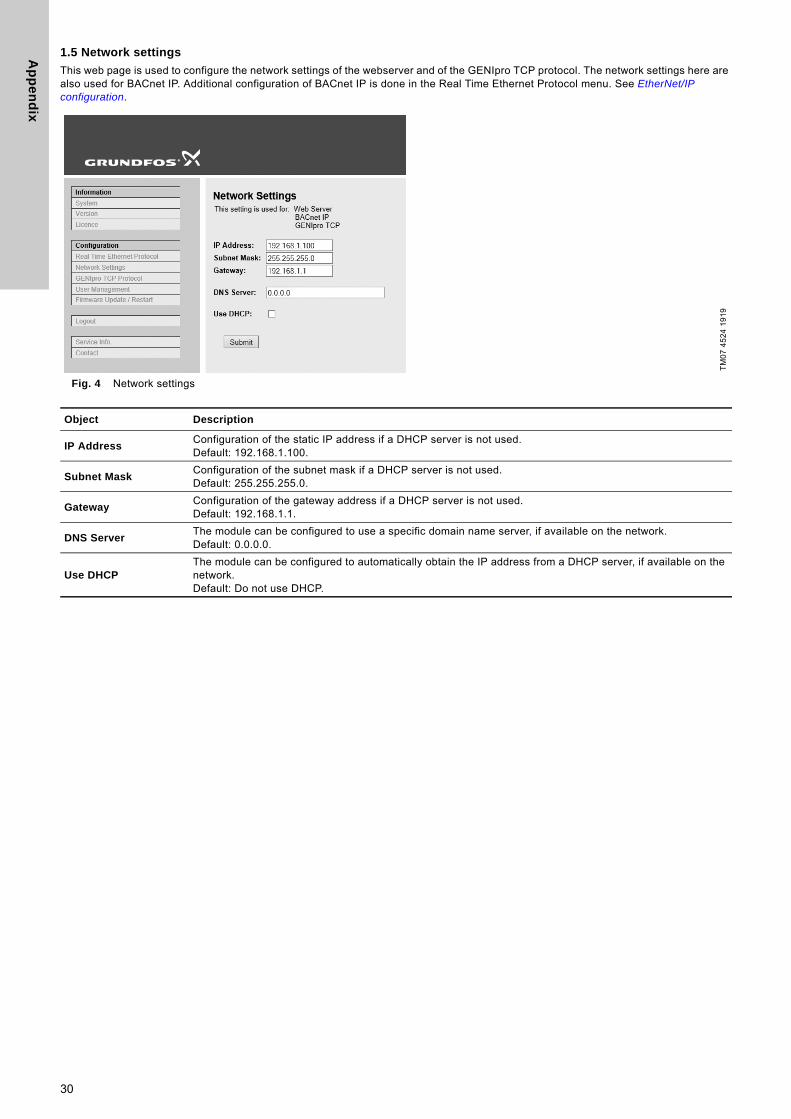
1.5 Network settings
This web page is used to configure the network settings of the webserver and of the GENIpro TCP protocol. The network settings here are also used for BACnet IP. Additional configuration of BACnet IP is done in the Real Time Ethernet Protocol menu. See EtherNet/IP configuration.
Fig. 4 Network settings
TM
07
45
24
19
19
Object Description
IP AddressConfiguration of the static IP address if a DHCP server is not used.Default: 192.168.1.100.
Subnet MaskConfiguration of the subnet mask if a DHCP server is not used.Default: 255.255.255.0.
GatewayConfiguration of the gateway address if a DHCP server is not used.Default: 192.168.1.1.
DNS ServerThe module can be configured to use a specific domain name server, if available on the network. Default: 0.0.0.0.
Use DHCPThe module can be configured to automatically obtain the IP address from a DHCP server, if available on the network. Default: Do not use DHCP.
30
Ap
pe
nd
ix
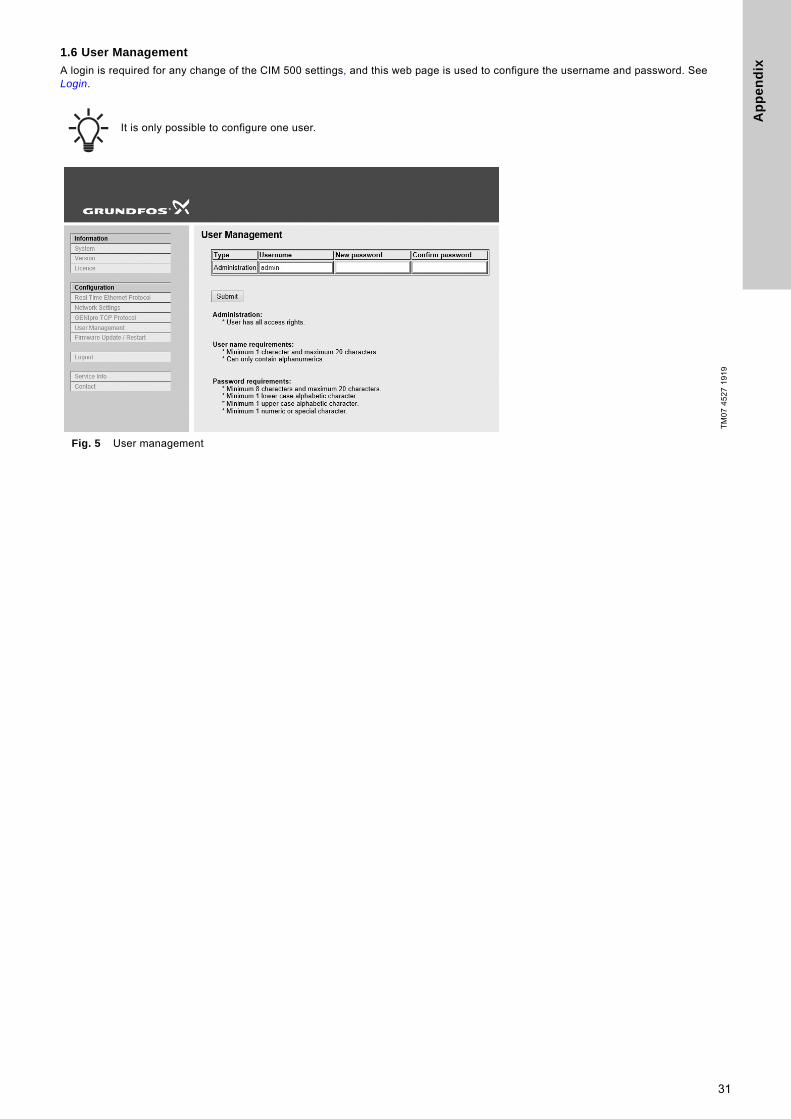
1.6 User Management
A login is required for any change of the CIM 500 settings, and this web page is used to configure the username and password. See Login.
Fig. 5 User management
It is only possible to configure one user.
TM
07
45
27
19
19
31
Ap
pe
nd
ix
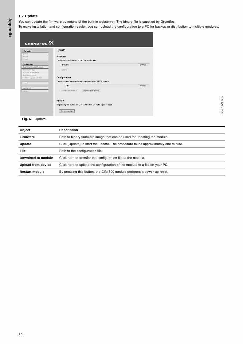
1.7 Update
You can update the firmware by means of the built-in webserver. The binary file is supplied by Grundfos.
To make installation and configuration easier, you can upload the configuration to a PC for backup or distribution to multiple modules.
Fig. 6 Update
TM
07
45
26
19
19
Object Description
Firmware Path to binary firmware image that can be used for updating the module.
Update Click [Update] to start the update. The procedure takes approximately one minute.
File Path to the configuration file.
Download to module Click here to transfer the configuration file to the module.
Upload from device Click here to upload the configuration of the module to a file on your PC.
Restart module By pressing this button, the CIM 500 module performs a power-up reset.
32

Gru
nd
fos
co
mp
anie
s
ArgentinaBombas GRUNDFOS de Argentina S.A.Ruta Panamericana km. 37.500 Centro Industrial Garin1619 Garín Pcia. de B.A.Phone: +54-3327 414 444Telefax: +54-3327 45 3190
AustraliaGRUNDFOS Pumps Pty. Ltd. P.O. Box 2040 Regency Park South Australia 5942 Phone: +61-8-8461-4611 Telefax: +61-8-8340 0155
AustriaGRUNDFOS Pumpen Vertrieb Ges.m.b.H.Grundfosstraße 2 A-5082 Grödig/Salzburg Tel.: +43-6246-883-0 Telefax: +43-6246-883-30
BelgiumN.V. GRUNDFOS Bellux S.A. Boomsesteenweg 81-83 B-2630 Aartselaar Tél.: +32-3-870 7300 Télécopie: +32-3-870 7301
BelarusПредставительство ГРУНДФОС в Минске220125, Минскул. Шафарнянская, 11, оф. 56, БЦ «Порт»Тел.: +7 (375 17) 286 39 72/73Факс: +7 (375 17) 286 39 71E-mail: [email protected]
Bosnia and HerzegovinaGRUNDFOS SarajevoZmaja od Bosne 7-7A,BH-71000 SarajevoPhone: +387 33 592 480Telefax: +387 33 590 465www.ba.grundfos.come-mail: [email protected]
BrazilBOMBAS GRUNDFOS DO BRASILAv. Humberto de Alencar Castelo Branco, 630CEP 09850 - 300São Bernardo do Campo - SPPhone: +55-11 4393 5533Telefax: +55-11 4343 5015
BulgariaGrundfos Bulgaria EOODSlatina DistrictIztochna Tangenta street no. 100BG - 1592 SofiaTel. +359 2 49 22 200Fax. +359 2 49 22 201email: [email protected]
CanadaGRUNDFOS Canada Inc. 2941 Brighton Road Oakville, Ontario L6H 6C9 Phone: +1-905 829 9533 Telefax: +1-905 829 9512
ChinaGRUNDFOS Pumps (Shanghai) Co. Ltd.10F The Hub, No. 33 Suhong RoadMinhang DistrictShanghai 201106PRCPhone: +86 21 612 252 22Telefax: +86 21 612 253 33
COLOMBIAGRUNDFOS Colombia S.A.S.Km 1.5 vía Siberia-Cota Conj. Potrero Chico,Parque Empresarial Arcos de Cota Bod. 1A.Cota, CundinamarcaPhone: +57(1)-2913444Telefax: +57(1)-8764586
CroatiaGRUNDFOS CROATIA d.o.o.Buzinski prilaz 38, BuzinHR-10010 ZagrebPhone: +385 1 6595 400 Telefax: +385 1 6595 499www.hr.grundfos.com
GRUNDFOS Sales Czechia and Slovakia s.r.o.Čajkovského 21779 00 OlomoucPhone: +420-585-716 111
DenmarkGRUNDFOS DK A/S Martin Bachs Vej 3 DK-8850 Bjerringbro Tlf.: +45-87 50 50 50 Telefax: +45-87 50 51 51 E-mail: [email protected]/DK
EstoniaGRUNDFOS Pumps Eesti OÜPeterburi tee 92G11415 TallinnTel: + 372 606 1690Fax: + 372 606 1691
FinlandOY GRUNDFOS Pumput AB Trukkikuja 1 FI-01360 Vantaa Phone: +358-(0) 207 889 500
FrancePompes GRUNDFOS Distribution S.A. Parc d’Activités de Chesnes 57, rue de Malacombe F-38290 St. Quentin Fallavier (Lyon) Tél.: +33-4 74 82 15 15 Télécopie: +33-4 74 94 10 51
GermanyGRUNDFOS GMBHSchlüterstr. 3340699 ErkrathTel.: +49-(0) 211 929 69-0 Telefax: +49-(0) 211 929 69-3799e-mail: [email protected] in Deutschland:e-mail: [email protected]
GreeceGRUNDFOS Hellas A.E.B.E. 20th km. Athinon-Markopoulou Av. P.O. Box 71 GR-19002 Peania Phone: +0030-210-66 83 400 Telefax: +0030-210-66 46 273
Hong KongGRUNDFOS Pumps (Hong Kong) Ltd. Unit 1, Ground floor Siu Wai Industrial Centre 29-33 Wing Hong Street & 68 King Lam Street, Cheung Sha Wan Kowloon Phone: +852-27861706 / 27861741 Telefax: +852-27858664
HungaryGRUNDFOS Hungária Kft.Tópark u. 8H-2045 Törökbálint, Phone: +36-23 511 110Telefax: +36-23 511 111
IndiaGRUNDFOS Pumps India Private Limited118 Old Mahabalipuram RoadThoraipakkamChennai 600 096Phone: +91-44 2496 6800
IndonesiaPT. GRUNDFOS POMPAGraha Intirub Lt. 2 & 3Jln. Cililitan Besar No.454. Makasar, Jakarta TimurID-Jakarta 13650Phone: +62 21-469-51900Telefax: +62 21-460 6910 / 460 6901
IrelandGRUNDFOS (Ireland) Ltd. Unit A, Merrywell Business ParkBallymount Road LowerDublin 12 Phone: +353-1-4089 800 Telefax: +353-1-4089 830
ItalyGRUNDFOS Pompe Italia S.r.l. Via Gran Sasso 4I-20060 Truccazzano (Milano)Tel.: +39-02-95838112 Telefax: +39-02-95309290 / 95838461
JapanGRUNDFOS Pumps K.K.1-2-3, Shin-Miyakoda, Kita-ku, Hamamatsu431-2103 JapanPhone: +81 53 428 4760Telefax: +81 53 428 5005
KoreaGRUNDFOS Pumps Korea Ltd.6th Floor, Aju Building 679-5Yeoksam-dong, Kangnam-ku, 135-916Seoul, KoreaPhone: +82-2-5317 600Telefax: +82-2-5633 725
LatviaSIA GRUNDFOS Pumps Latvia Deglava biznesa centrsAugusta Deglava ielā 60, LV-1035, Rīga,Tālr.: + 371 714 9640, 7 149 641Fakss: + 371 914 9646
LithuaniaGRUNDFOS Pumps UABSmolensko g. 6LT-03201 VilniusTel: + 370 52 395 430Fax: + 370 52 395 431
MalaysiaGRUNDFOS Pumps Sdn. Bhd.7 Jalan Peguam U1/25Glenmarie Industrial Park40150 Shah AlamSelangor Phone: +60-3-5569 2922Telefax: +60-3-5569 2866
MexicoBombas GRUNDFOS de México S.A. de C.V. Boulevard TLC No. 15Parque Industrial Stiva AeropuertoApodaca, N.L. 66600Phone: +52-81-8144 4000 Telefax: +52-81-8144 4010
NetherlandsGRUNDFOS NetherlandsVeluwezoom 351326 AE AlmerePostbus 220151302 CA ALMERE Tel.: +31-88-478 6336 Telefax: +31-88-478 6332E-mail: [email protected]
New ZealandGRUNDFOS Pumps NZ Ltd.17 Beatrice Tinsley CrescentNorth Harbour Industrial EstateAlbany, AucklandPhone: +64-9-415 3240Telefax: +64-9-415 3250
NorwayGRUNDFOS Pumper A/S Strømsveien 344 Postboks 235, Leirdal N-1011 Oslo Tlf.: +47-22 90 47 00 Telefax: +47-22 32 21 50
PolandGRUNDFOS Pompy Sp. z o.o.ul. Klonowa 23Baranowo k. PoznaniaPL-62-081 PrzeźmierowoTel: (+48-61) 650 13 00Fax: (+48-61) 650 13 50
PortugalBombas GRUNDFOS Portugal, S.A. Rua Calvet de Magalhães, 241Apartado 1079P-2770-153 Paço de ArcosTel.: +351-21-440 76 00Telefax: +351-21-440 76 90
RomaniaGRUNDFOS Pompe România SRLBd. Biruintei, nr 103 Pantelimon county IlfovPhone: +40 21 200 4100Telefax: +40 21 200 4101E-mail: [email protected]
RussiaООО Грундфос Россияул. Школьная, 39-41Москва, RU-109544, Russia Тел. (+7) 495 564-88-00 (495) 737-30-00Факс (+7) 495 564 8811E-mail [email protected]
Serbia Grundfos Srbija d.o.o.Omladinskih brigada 90b11070 Novi Beograd Phone: +381 11 2258 740Telefax: +381 11 2281 769www.rs.grundfos.com
SingaporeGRUNDFOS (Singapore) Pte. Ltd.25 Jalan Tukang Singapore 619264 Phone: +65-6681 9688 Telefax: +65-6681 9689
SlovakiaGRUNDFOS s.r.o.Prievozská 4D 821 09 BRATISLAVA Phona: +421 2 5020 1426sk.grundfos.com
SloveniaGRUNDFOS LJUBLJANA, d.o.o.Leskoškova 9e, 1122 LjubljanaPhone: +386 (0) 1 568 06 10Telefax: +386 (0)1 568 06 19E-mail: [email protected]
South AfricaGrundfos (PTY) Ltd.16 Lascelles Drive, Meadowbrook Estate1609 Germiston, JohannesburgTel.: (+27) 10 248 6000Fax: (+27) 10 248 6002E-mail: [email protected]
SpainBombas GRUNDFOS España S.A. Camino de la Fuentecilla, s/n E-28110 Algete (Madrid) Tel.: +34-91-848 8800 Telefax: +34-91-628 0465
SwedenGRUNDFOS AB Box 333 (Lunnagårdsgatan 6) 431 24 Mölndal Tel.: +46 31 332 23 000Telefax: +46 31 331 94 60
SwitzerlandGRUNDFOS Pumpen AG Bruggacherstrasse 10 CH-8117 Fällanden/ZH Tel.: +41-44-806 8111 Telefax: +41-44-806 8115
TaiwanGRUNDFOS Pumps (Taiwan) Ltd. 7 Floor, 219 Min-Chuan Road Taichung, Taiwan, R.O.C. Phone: +886-4-2305 0868Telefax: +886-4-2305 0878
ThailandGRUNDFOS (Thailand) Ltd. 92 Chaloem Phrakiat Rama 9 Road,Dokmai, Pravej, Bangkok 10250Phone: +66-2-725 8999Telefax: +66-2-725 8998
TurkeyGRUNDFOS POMPA San. ve Tic. Ltd. Sti.Gebze Organize Sanayi Bölgesi Ihsan dede Caddesi,2. yol 200. Sokak No. 20441490 Gebze/ KocaeliPhone: +90 - 262-679 7979Telefax: +90 - 262-679 7905E-mail: [email protected]
UkraineБізнес Центр ЄвропаСтоличне шосе, 103м. Київ, 03131, Україна Телефон: (+38 044) 237 04 00 Факс.: (+38 044) 237 04 01E-mail: [email protected]
United Arab EmiratesGRUNDFOS Gulf DistributionP.O. Box 16768Jebel Ali Free ZoneDubaiPhone: +971 4 8815 166Telefax: +971 4 8815 136
United KingdomGRUNDFOS Pumps Ltd. Grovebury Road Leighton Buzzard/Beds. LU7 4TL Phone: +44-1525-850000 Telefax: +44-1525-850011
U.S.A.GRUNDFOS Pumps Corporation 9300 Loiret Blvd.Lenexa, Kansas 66219Phone: +1-913-227-3400 Telefax: +1-913-227-3500
UzbekistanGrundfos Tashkent, Uzbekistan The Repre-sentative Office of Grundfos Kazakhstan in Uzbekistan38a, Oybek street, TashkentТелефон: (+998) 71 150 3290 / 71 150 3291Факс: (+998) 71 150 3292
Addresses Revised 15.01.2019

99720819 1019
ECM: 1270210 Trad
emar
ks d
ispl
ayed
in th
is m
ater
ial,
incl
udin
g bu
t not
lim
ited
to G
rund
fos,
the
Gru
ndfo
s lo
go a
nd “b
e th
ink
inno
vate
” are
regi
ster
ed tr
adem
arks
ow
ned
by T
he G
rund
fos
Gro
up. A
ll rig
hts
rese
rved
.©
201
9 G
rund
fos
Hol
ding
A/S
, all
right
s re
serv
ed.
www.grundfos.com