ethernet transport - cigred2.cigre.org/content/download/11349/333984/version/2/file/ip_part3... ·...
TRANSCRIPT

Ethernet Transportin Power Utility Communication
Networks

Agenda
• Introduction• IP Solution for layer3• Ethernet transport• Operational services implementation• Examples

Infrastructure
Services
IP
?
IP Convergence in Utility Networks
Everything can be carried over IP
IP can be carried over everything
Voice, Data, Video, Storage

POS (Packet over SDH)
Poor Bandwidth Granularity E1, E3, STM1 No Bandwidth Flexibility
SDH
IP/PPP
RR
R
E3
E3
E1 E1E3
E3

Classical IP over ATM (CIOA)
SDH
ATM
IP
RR
R
Complexity of Signaling Multiple Control Planes independent of each other

Overlay Network Model
WDM/ Fiber
SDH
ATM
Ethernet
IP

Why Ethernet ?
98% of all data traffic in all enterprise start and end on an Ethernet port easy to understand, implement, manage and maintain low cost strong industry support continuous development (switching, speed, fiber, wireless, ...) extensive topological flexibility covers from Local to Wide Area Networking
most dominant standard in the networking industry IEEE 802.3 / ISO 8802.3
30 years of history developed in the 70s 1983 : IEEE std early 90’s : Switched Ethernet 1997 : Fast Ethernet 100Mbps 1999 : Gigabit Ethernet 1Gbps 2002 : 10 Gigabit Ethernet ( IEEE802.3ae)
Has become the “IP” of local area networking

Switched Ethernet
Repeater-based system : All stations in the same Collision Domain
Switched Ethernet : Each point-to-point link is a Collision Domain Half Duplex operation - only possible collision is between the two ends
Full Duplex operation - no collision detection limitations Non-saturating switch - capable of accepting and transferring full rate
data from each port simultaneously
Repeater Repeater Switch Switch
Collision domains

Full Duplex Operation
Allows simultaneous 2-way transmission over point-to-point links Functionally much simpler (IEEE 802.3x)
no contention, collision, retransmission scheduling no extension bits at the end of short frames more time available for transmission transmission can start as soon as frames are ready to send
Must respect a minimum inter-frame gap Requires implementation of Flow Control
allows a congested receiving port to request a pause from the sending node (Pause Frame)
if relieved before Pause expiration, a new Pause frame (time-to-wait=0)is sent
MAC FrameIFG IFGMAC Frame MAC Frame
MAC FrameIFG IFGMAC Frame MAC Frame

IEEE 802.3 PHY Layer Standards 10Mbps :
10BaseT, Baseband Manchester coded, 2 Unshielded Twisted Pairs (UTP) each configured as Simplex
100Mbps Fast Ethernet / 100BaseX IEEE 802.3u merged into 2002 edition of IEEE 802.3 100Base-TX, 2 Cat 5 UTP copper pairs 100Base-FX, 2 fibers, FDDI optical transceivers
1000Mbps Gigabit Ethernet IEEE 802.3z merged into 2002 edition of IEEE 802.3 1000Base-X, ANSI FiberChannel encoding (8B10B) 1000Base-CX, 2 STP copper pairs 1000Base-SX, 850nm, 2 Multi-mode Fibers 1000Base-LX/LH, 1300nm, 2 Multi-mode or Single-mode Fibers 1000Base-T, (IEEE 802.3ab)
4 Full Duplex 125Mbd streams through Hybrid over 4 UTP pairs 4-dimensional 8-state Trellis Coding (each dimension:250Mbps, 2bits) Each dimension is PAM5 modulated
1000Base-ZX, Extended Reach over SM or DS Fibers
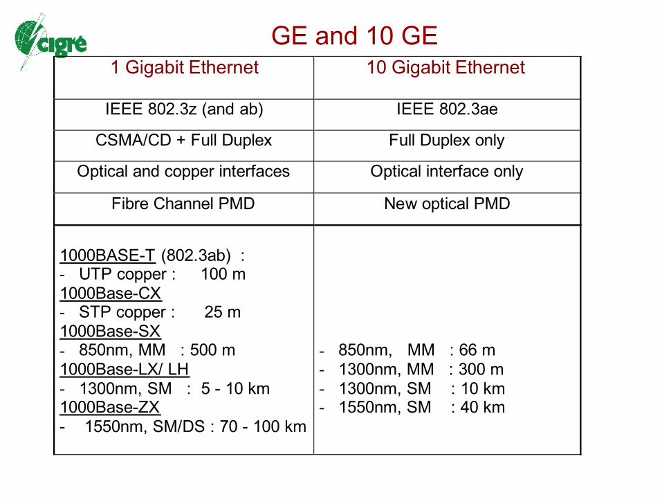
GE and 10 GE1 Gigabit Ethernet 10 Gigabit Ethernet
IEEE 802.3z (and ab) IEEE 802.3ae
CSMA/CD + Full Duplex Full Duplex only
Optical and copper interfaces Optical interface only
Fibre Channel PMD New optical PMD
1000BASE-T (802.3ab) :- UTP copper : 100 m1000Base-CX- STP copper : 25 m1000Base-SX- 850nm, MM : 500 m1000Base-LX/ LH- 1300nm, SM : 5 - 10 km1000Base-ZX- 1550nm, SM/DS : 70 - 100 km
- 850nm, MM : 66 m- 1300nm, MM : 300 m- 1300nm, SM : 10 km- 1550nm, SM : 40 km

“Bridging Entity” Functions
IEEE 801 Standards

Priority Queuing
IEEE 802.1p (Now part of 802.1d) Expedited traffic capability for time-critical information Provision of Filtering services that support dynamic use of Group MAC
addresses Associates a set of properties with a group MAC address Defines membership characteristics for the group Defines forwarding /filtering behavior for frames destined to the group
Comprises Generic Attribute Registration Protocol (GARP) Adds Traffic class functionality (Class of Service)
Introduces user priority Allows individual end station to request a particular CoS in the network
user priority field in 802.1Q tag header through configuration

Virtual LAN (VLAN)
Logical LAN or Broadcast Domain over a shared physical network IEEE801Q : Virtual Bridged Local Area Network Provides a means to expedite time-critical network traffic
set transmission priorities for outgoing frames
Allows dispersed devices to communicate as if they were attached to the same wire (i.e. on a single LAN) allows stations to be assigned to logical groups (Broadcast Domains) examines frames, and records (learns) egress port for each MAC address bridges and switches frames only to ports that serve the specific VLAN Breaks large networks into smaller parts so that broadcast traffic will not
consume excessive bandwidth
Based on logical connection through Tagging of Ethernet frames
4-byte VLAN Header (Tag) carry VLAN membership information 2 bytes : Type ID 2 bytes : Tag Control 12 bit VLAN identity (VID) identifies each VLAN (4096 VIDs) 3 bits Transmission Priority (0 to 7) (+1 bit format indicator)

VLAN Tunneling
• Allows to transport several VLANs through a single “grouped” VLAN• Simple encapsulation scheme (Q-in-Q)• Multiple Q-Tags added to the frame (VLAN stacking)• Allows to overcome limited VLAN IDs• Allows to create hierarchical structures of VLAN
VLAN10
VLAN20
VLAN30
VLAN40
VLAN30
VLAN40
VLAN10
VLAN20

Network Restoration - Spanning Tree
Ethernet switch examines frames and records (learns) egress port for each MAC address if MAC address is unknown, the frame is “flooded” to all ports if network contains loops, “flooding” leads to a “Broadcast Storm”
consuming available bandwidth
Spanning Tree Protocol (STP) IEEE 802.1d Prevents loops by converting the network into a tree structure spanning all
the switches Switches send Identity and “link cost” messages to each other Elect one switch as “Root” or central switch Other switches calculate direction and cost for Shortest Path to the Root Only one “best way” of frame forwarding for each switch Takes 30 to 60sec to converge (depending on size and topology)

Multiple Spanning Trees
Spanning Tree may be defined “per VLAN” IEEE 802.1s Multiple Spanning Trees
STP
STP
VLAN X
VLAN Y
Root
Root

Multi-Instance Spanning Tree (MISTP)
Large number of VLANs but only 2 logical topologies – why run many STP algorithms ?
Map half the VLANs to a common Spanning Tree instance and the other half to another instance
Only one BPDU sent and one topology maintained per instance Improve scalability (reduced processing time)
R(Ev) R(Odd)Root for Even VLANs
Root for Odd VLANs
Fwd Even VLANsBlock Odd VLANs Fwd Odd VLANs
Block Even VLANs

Rapid Spanning Tree Protocol (RSTP)
IEEE 802.1w - standard 2001 Extension of 802.1d (compatible) New mechanism for better convergence Specifies a single SP for all VLANs
industry implementations allow one ST per VLAN
Can converge in 1 to 3 sec

Ethernet Transport
Fiber
WDM
SDH
ResilientPacketRing
SwitchedEthernet
IP / MPLS

Gigabit Ethernet Use in the MAN
Gigabit Ethernet Hub-and-Spoke Single or Dual Homing Requires N links with no protection Requires 2N links for a protected
network
Gigabit Ethernet Ring Protection through the topology Requires N shorter links Less scalable than the Hub-and-
spoke

Ethernet over SDH / Sonet

Ethernet over SDH (EoS)
Efficient use of existing SDH infrastructure Deliver Ethernet services flexibility with SDH Restore Time (50ms) Add optimized data services in a network with TDM circuit
requirements Ethernet frame is encapsulated inside an EoS Header, Mapped into
the SDH Payload and transported as an SDH Tributary Two ways to transport Ethernet Frames through SDH
LAPS - Link Access Procedure ITU-T X86 connectionless protocol Not used anymore
GFP - Generic Framing Procedure ITU-T G7041 can accommodate other frames than Ethernet (PPP, FiberChannel,
Fiber Connectivity FICON, Enterprise Systems Connection ESCON
EoS interface can be in the ADM or in the Switch

Virtual Concatenation (VCAT)
ITU-T G707 A measure to reduce TDM bandwidth inefficiency on SDH
Classical SDH has coarse bandwidth granularity inefficient for Ethernet E1 (2M), E3 (34M), STM-1 (155M), STM-4 (622M), STM-16 (2.5G) Ethernet : 10M, 100M, 1000M
once the circuit is allocated, the system loses the bandwidth (whether used or not)
VCAT concatenates a number of smaller pipes to create a bigger pipe seen by upper layers as one physical pipe 100M = 3 x E3 instead of 1 x STM-1 (no wasted bandwidth) speed of EoS mapping does not have to match the speed of Ethernet
interface (i.e FE over 50M) Allows grouping of N x STM or N x VC

Link Capacity Adjustment Scheme (LCAS)
Customer bandwidth requirement can change over time Leads to capacity “Churn” in time (channels added and removed)
VCAT pipes must be resized
LCAS ITU-T G7072 Allows channels to be resized without disrupting the traffic or the link
Performs connectivity checks to allow failed links to be removed and new links to be added dynamically without network disruptions.

EoS with Switching and Aggregation
EOS provides “Packet Mapping” not “Packet Switching / Multiplexing” Multi-Service Provisioning Platforms (MSPP)
Integrate required switches locally in each SDH node Allows switch functions dispersed into the network
Multiple users on one physical interface Service Aggregation at the “Central Office”
- many customer Ethernet wires into a Trunk at the central site
VLAN, Q-in-Q, RSTP
LSLS
LS ADM
ADM
ADM ADM
ADM
ADM LS
LS LS
Customer ASite 2
Customer BSite 2
Customer ASite 2
Customer BSite 2
Central Site A
Central Site B
SDH Ring Network

Resilient Packet Ring (RPR)
New Media Access Control (MAC) protocol IEEE 802.17 Designed to optimize bandwidth management Deploy data services on a Ring Network Deployed over dark fiber or WDM
Can also be deployed as overlay on SDH
Add, Drop and Forward functions forwards traffic on the ring without any intermediate switching or buffering in Ethernet the transit traffic is processed and buffered at each node
Packets on the ring share the full bandwidth (like Ethernet, unlike SDH) Offers Ring protection in 50ms (like SDH, unlike Ethernet)
Use 100% of Ring capacity (no dedicated capacity for protection) Fault detected in the PHY layer, traffic redirection managed by MAC
Fairness algorithm - give every node on the ring a fair share of bandwidth bound latency on the ring

Emulated Ethernet Services Move from Single-customer to Many-customer environment
Scalability issues for Service Providers Encapsulation schemes over a “Provider’s IP / MPLS network” May be applicable to utilities with a very large telecommunication
infrastructure (many internal and external “customers”) Applies to Utilities with outsourced telecom infrastructure
Provide a Hierarchical Hybrid Architecture L2 Ethernet Simple but not Scalable L3 IP/MPLS Scalable but Complex
IP / MPLSL2 Ethernet L2 Ethernet
CE PE PE CE
Metro / Edge Core

Ethernet over IP / MPLS
L2 Ethernet service across IP / MPLS can be point-to-point (P2P) or mutipoint-to-multipoint (MP2MP)
P2P Ethernet Service Packet Leased line concept : Pseudo-wire (PW) L2TPv3 (L2 Tunneling Protocol) over an IP network Ethernet over MPLS known as draft-Martini (author of the original draft)
MP2MP Ethernet Service VPLS (Virtual Private LAN Service)

Muti-Protocol Label Switching (MPLS)
Not a communication protocol but a Forwarding Technique Forwarding Equivalence Classes (FEC) Currently called “layer 2.5”
A way to transport IP packets using “Label Swapping” Allows ATM-type Connection-Oriented operation for IP datagrams
using a Unified Control Plane (Label Switched Path, LSP) Switching based on a label, not on the datagram header Allows to deploy QoS / Traffic Engineering (TE)
Mapping of Traffic demand (traffic matrix) onto a network topology and the ability to control traffic flows in the network.
Measurement, modeling, characterization and control of IP traffic for optimizing the performance of operational networks
Allows to deploy unified MultiService Networks through L2 / L3 Virtual Private Networks

EoMPLSVirtual Circuit Labels
DA(6) SA(6) CNT(2) Payload (46 – 1500 Bytes)
PayloadStackEntry N … Stack
Entry 1
Ethernet Frame
L2 Encapsulation
CRC(4)
Ethernet over MPLS (L2VPN)
MPLS over Ethernet
IP PacketStackEntry N … Stack
Entry 1
DA(6) SA(6) CNT(2) Payload (46 – 1500 Bytes) Ethernet FrameCRC(4)
Ethernet
IP / MPLS
Emulated Ethernet Service
IP / MPLS
Ethernet
Use Ethernet Transport for an IP / MPLS
network
This is not EoMPLS

VPLS
Scalability issues in Native Ethernet MAC Address Table “Explosion”
Switches learning MAC address per port for the whole network
Number of VLANs and their management
Virtual Private LAN Service (VPLS) Provides a switched Ethernet LAN over an IP/MPLS network Uses MPLS layer 2 encapsulation (Martini-Draft) as building block Greatly benefits from MPLS features
Traffic Engineering Fast Protection against node/link failure Bandwidth guarantee through RSVP-TE

Ethernet over MPLS L2VPN P2P
• Draft Martini

Implementationsin the Power Utility
Communications Network

Substation Ethernet
IEEE 802.3x Full Duplex Operation no collisions, deterministic behavior
IEEE 802.1p Priority Queuing Priority level Tagging for real-time
traffic
IEEE 802.1Q VLAN isolate real-time IEDs from data collection
IEEE 802.1w Rapid Spanning Tree Fault Tolerant architectures
IEDA1
IEDA2
IEDA3
IEDAn
IEDB1
IEDB2
IEDB3
IEDBn
Substation hardening requiredIEC 61850 Part 3 - Section 5.7
ProtectionIED Kiosks
Control Building
Substation HMI Substation Controller
Wide Area Network
Protected Area
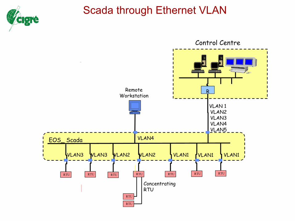
EOS_ Scada
RTU RTU
RTU
RTU
RTU
R
Control Centre
RemoteWorkstation
RTURTU
VLAN1VLAN1
RTU RTU
VLAN1VLAN2VLAN2VLAN3VLAN3
VLAN4
VLAN 1 VLAN2VLAN3VLAN4VLAN5
Concentrating RTU
Scada through Ethernet VLAN

Scada through VLAN
EOS_ Scada
RTU
R
Backup Control Centre
RTU
VLAN1
RTU
VLAN1VLAN2VLAN3
VLAN 1B VLAN2BVLAN3BVLAN4BVLAN5B
R
Control Centre
VLAN 1A VLAN2AVLAN3AVLAN4AVLAN5A
RTU

VLAN / VPN in Utility Communications
FunctionalCommunication
Planes
IT
Voice & Multimedia
SCADA & EMS
Monitoring & TMS
Protection & Control
Cont
rol Ce
ntre
Powe
r Plan
t
Subs
tation
Hea
dqua
rter
Net 1
Net 2
Net 3
Net 4
Net 5

R
RTU
R
RTU
R
RTU
R
PABX
DPLC
RTU
RTU
RTU
RTU
IED
DCS
IED
S/SLAN
R
IED IED
DCSS/SLAN
R
ProtectionE-Line
IED IED
ControlCentre
R R
EOS_ Control
S/SLANs
RTU
RTU
RTU
RadioEthernet
RTURTURTU
EOS_ Scada
RTU RTU
RRRR
RemoteWorkstation

Service Provider Ethernetin Metropolitan Area
Metro Ethernet

What is a Metro Ethernet Network (MEN) ? Ethernet-based MAN
Provide Ethernet services to customer sites dispersed across a Metropolitan domain Operates as if multiple networks are connected as a single LAN bridges or connects geographically separated enterprise LANs provide connectivity services across Metro geography utilizing Ethernet as the core
protocol and enabling broadband applications Nodes (switches or routers) are meshed to provide desired connectivity,
services and protection Customer VLAN : collection of multiple LANs physically connected to a shared
“Service Provider Network” (SPN) SPN is transparent to customer’s LAN segments MEN-like technology extending into WAN Simple migration path to higher performance levels - from 10 Mbps to 1
Gbps and beyond Clear migration path - leverage existing Ethernet protocol Provides scalable connectivity by site, bandwidth on demand Supports expansion without disruption

Ethernet Connectivity Services
Point-to-PointE-Line
Multipoint-to-MultipointE-LAN
Port-Based ServiceNo Service MultiplexingDedicated Bandwidth
Ethernet Private LineEPL
Ethernet Private LANEPLAN
VLAN-Based ServiceService MultiplexingShared Bandwidth
Ethernet Virtual Private LineEVPL
Ethernet Virtual Private LANEVPLAN
Most widely deployed, simplest to delivercan be offered with strong SLA

Why use Ethernet in the Metro Customer View (reduce cost)
Reliable and “less expensive alternative to Leased lines More efficient bandwidth procurement (provisioned on demand 1-1000 M) ability to upgrade bandwidth quickly affordable protection schemes Improved Enterprise Network Management High bandwidth and low latency applications (Storage area networking,
disaster recovery, packetized voice applications, video applications Service Provider View (increase revenue)
More efficient use of infrastructure Richer set of services Scalable bandwidth Technology evolution and cost decrease Drive down capital and operational costs and increase reliability Fast and easy deployment of new applications Reliable design Architectural stability Simplified network architecture, engineering and design, reduced engineering complexity (transparent transport) topological flexibility to mesh sites Flexible high capacity solutions simplify network architecture

Metro Ethernet Forum
ADVA Optical Networking Agilent Technologies Alcatel Appian Communications AT&T Bell South British Telecom (BT) CIENA Cisco Systems France telecom Fujitsu Huawei Technologies Juniper Networks
Lucent Technologies Marconi Nortel Networks NTT PMC - SIERRA Quest RAD Scientific Atlanta Siemens Telcordia Technologies Tellabs ZTE

Bandwidth problem in the operators’ access network

Ethernet in the First Mile (EFM)
Deliver multimedia services in the professional and residential domain
Integrate Voice/Data/Video over a unified IP/Ethernet
Cover the last km
Fast internet, VoIP, LAN-to-LAN (VPN)
Unicast and Muticast Video (800kbps to 5/6Mbps)
IEEE802.3ah July 2004
Aso called Metro, local loop, “last mile”, ETTX, ETTH (Home), ETTB (Business)
Ethernet/ IP transport and Ethernet interface at user premises


EFM – Possible Optical Topologies
• Point-to-point Ethernet– N fibres– 2N Transceivers
• Switched Ethernet– 2 fibres– 2N+2 Transceivers– Minimal space in CO– Active hardware out of CO
• Ethernet PON– 1 fibre– Minimal space in CO– N+1 Transceivers
CO
Ex. 32 Nodes64 fibres64 transceivers
CO
Ex. 32 Nodes1 fibre33 transceivers
PassiveSplitter
P2MP
P2P
CO
Ex. 32 Nodes2 fibres66 transceivers
CurbSwitch
P2P

EPON Downstream Flow
Full Duplex Gigabit Ethernet continuous flow Passive splitter for 32 optical fibres Wavelength multiplexing of upstream and downstream
flow (one fibre)
Users
802.3 frames
OpticalNetwork
Units
PassiveOpticalSplitter
OpticalLine
Terminal

EPON Upstream Flow
TDMA (time slot allocated to each user) No collision Bandwidth allocation according to SLA
Users
802.3 frames
OpticalNetwork
Units
PassiveOpticalSplitter
OpticalLine
Terminal