etch and pattern transfer ii - massachusetts institute of technology
TRANSCRIPT

6.152J / 3.155J Spring Term 2005 Lecture 14--Etch and Pattern Transfer II
Dry Etch 1
6.152J / 3.155J --Spring Term 2005 Lecture 14 -- Etch II ( Dry Etch) 1
Etch and Pattern Transfer II
Outline•Review of Plasma Processes•Plasma Etch Mechanisms
–Chemical Etching–Physical Etching (sputtering)–Ion Enhanced Etching
•Plasma Reactors•Dry Etch Chemistry
Reading Assignment: Plummer, Chapter 10
Reference: The Science and Engineering of Microelectronic Fabrication, Campbell, Chapter 11
6.152J / 3.155J --Spring Term 2005 Lecture 14 -- Etch II ( Dry Etch) 2
Gas Phase (Plasma) Etching
• Reactive chemical component of plasma etching often has high selectivity
• Ionic component of plasma etching often has directionality
• Utilizing both components, directionality could be achieved while maintaining an acceptable selectivity
Film
Substrate
PR
ReactantsReaction Products
Diffusion Diffusion
Reaction
Boundary Layer
Driftor / andDiffusion
Diffusion
DriftDiffusion

6.152J / 3.155J Spring Term 2005 Lecture 14--Etch and Pattern Transfer II
Dry Etch 2
6.152J / 3.155J --Spring Term 2005 Lecture 14 -- Etch II ( Dry Etch) 3
Review of RF Plasmas• Application of electric field across
two electrodes gas • Atoms/molecules are ionized,
producing positive ions and free electrons, creating a plasma
• Voltage bias develops between the plasma and electrodes because of the difference in mobilities(masses) of electrons and ions
• Plasma is positively biased with respect to the electrodes
Pressure: 1 mTorr – 1 Torr
Energy: RF Source @ 13.56 MHz
6.152J / 3.155J --Spring Term 2005 Lecture 14 -- Etch II ( Dry Etch) 4
RF Plasma Potential Profile• Sheaths form next to electrodes
and voltage drops occur at sheaths corresponding to dark region
• Ions respond to the average sheath voltage while the electrons respond to instantaneous voltage
• If electrodes have equal areas, the voltage drop at the sheaths are symmetrical
• If the electrodes have un-equal areas, the voltage drop between the sheaths and the electrodes are asymmetrical with a much larger voltage drop occurring at the smaller electrode
– Two capacitors in series
Plummer, Fig 10.8
1 2V V=
4
21 2
1
AV VA
⎛ ⎞= ×⎜ ⎟
⎝ ⎠

6.152J / 3.155J Spring Term 2005 Lecture 14--Etch and Pattern Transfer II
Dry Etch 3
6.152J / 3.155J --Spring Term 2005 Lecture 14 -- Etch II ( Dry Etch) 5
Review of Plasma ProcessesFor a plasma with inlet flow of molecule AB, Plasma processes are
Dissociation
e* + AB A + B + e
Atomic Ionization
e* + A A+ + e + e
Molecular Ionization
e* + AB AB+ + e + e
Atomic Excitation
e* + A A* + e
Molecular Excitation
e* + AB AB* + ePlummer, Fig 10.9
6.152J / 3.155J --Spring Term 2005 Lecture 14 -- Etch II ( Dry Etch) 6
Review of Plasma Processes
• Two types of species are involved in plasma etching– Free energetic molecular or atomic radicals which are responsible
for chemical etching– Atomic or molecular ions which are responsible for physical
etching(sputtering)• When free radicals act by themselves the mechanism is
chemical etching• When ions act by themselves the mechanism is physical
etching or sputtering• When radicals and ions act synergistically, the mechanism
is ion enhanced etching
At a pressure of 20 mT the plasma consist of
Neutral Species 1015 cm-3
Reactive Neutral Species 1012 – 1013 cm-3
Ions and Electrons 108 – 1012 cm-3

6.152J / 3.155J Spring Term 2005 Lecture 14--Etch and Pattern Transfer II
Dry Etch 4
6.152J / 3.155J --Spring Term 2005 Lecture 14 -- Etch II ( Dry Etch) 7
Plasma Etch MechanismsChemical
• Free radicals are electrically neutral species that have incomplete outer shells e.g. CF3 and F
• Free radicals react with film to be etched e.g. Si
• The reaction product must be volatile• Mass transport of reactive species and
products to & from the reaction surface.
• Other gasses are sometimes added to increase chemical etch rate– e.g. oxygen is added to CF4 plasma to
increase the amount of reactive F species (O reacts with CF3 and CF2 and hence reduce the recombination rate of F)
eFCFCFe ++→+−34
44 SiFFSi →+
Plummer, Fig 10.10
6.152J / 3.155J --Spring Term 2005 Lecture 14 -- Etch II ( Dry Etch) 8
Chemical Etch• Chemical etching is very
selective because free radicals etch by chemical reaction which can be very specific
• Chemical component of plasma etching when acting by itself, is isotropic, but need to consider also– Distribution of arrival angles– Sticking coefficient
• Free radicals in plasma systems have isotropic arrival angles and low sticking coefficients
Plummer, Fig 10.11

6.152J / 3.155J Spring Term 2005 Lecture 14--Etch and Pattern Transfer II
Dry Etch 5
6.152J / 3.155J --Spring Term 2005 Lecture 14 -- Etch II ( Dry Etch) 9
Physical Etch• Ions are accelerated towards each
electrode by electric field created by the voltage drop between the plasma and the electrode
• The ionic species such as Cl2+, CF4
+, CF3
+ (or Ar+) strike the wafer surface with high momentum– Atoms are dislodged into the gas stream– Mass transport from the boundary layer
into the gas stream• The ions (and hence the etch) are
very directional due to the electric field
• Etching is not very selective – Sputtering yield from most materials do
not vary much Plummer, Fig 10.11
6.152J / 3.155J --Spring Term 2005 Lecture 14 -- Etch II ( Dry Etch) 10
Ion Enhanced Etch (1)• Experimental work on Si etch in XeF2 gas
and Ar+ ions show that– With XeF2 gas only, very little etching
occurs– With Ar+ ion beam and XeF2 gas, high etch
rate occurs– With Ar+ ion beam only, very little etching
occurs• While ion enhanced etching (IEE) has both
chemical and physical components, the profiles are very anisotropic with no lateral etch
– The etch profile is not a linear combination of the profiles
• IEE has excellent selectivity because both physical and chemical components are required at each point in the process
Plummer, Fig 10.12

6.152J / 3.155J Spring Term 2005 Lecture 14--Etch and Pattern Transfer II
Dry Etch 6
6.152J / 3.155J --Spring Term 2005 Lecture 14 -- Etch II ( Dry Etch) 11
Ion Enhanced Etch (2)
• Ion enhanced etching has both chemical and physical components that act synergistically to provide excellent anisotropic profiles and selectivity– Surface adsorbtion, etching reaction, by-product formation, by-
product removal (inhibitor layer) and removal of un-reacted etchants• Example: inhibitor layer formed from C2F6 during reactive
ion etch of SiO2– Polymer coats sidewalls– Enahancement where the polymer has been removed by ion
bombardment
Plummer, Fig 10.13
6.152J / 3.155J --Spring Term 2005 Lecture 14 -- Etch II ( Dry Etch) 12
Ion Enhanced Etch (3)
Effect of inhibitor deposition on resulting sidewall slope
Different inhibitor deposition rates result in different sidewall slopes
Plummer, Fig 10.14

6.152J / 3.155J Spring Term 2005 Lecture 14--Etch and Pattern Transfer II
Dry Etch 7
6.152J / 3.155J --Spring Term 2005 Lecture 14 -- Etch II ( Dry Etch) 13
Gas Phase Etch ReactorsBarrel Etchers
• Reactant chemical species diffuse through the tunnel to wafers where they etch the surface
• No ionic bombardment occurs because the plasma is kept away from wafers– Etch is purely chemical, very selective and isotropic– Etch uniformity is not good because of the long diffusion path for the
reactive species
• Barrel etches are mainly used for removal of PR
Plummer, Fig 10.15
6.152J / 3.155J --Spring Term 2005 Lecture 14 -- Etch II ( Dry Etch) 14
Parallel Plate EtchersPlasma Mode
• Ions bombard the wafer surface– Physical component of etching
leads to anisotropicity– Gas pressure of 100 mTorr – 1 Torr
reduces physical component
• Voltage distribution symmetrical for equal sized electrodes with a drop between 10 and 100 eV
• Voltage drop much smaller and etching is mostly chemical for grounded chamber wall– Etch is selective, highly uniform
with fair directionality
Plasma
Electrode
Electrode
Plasma Sheaths
Matching Network
RF Generator
RF Input PowerBlocking Capacitor
Gas Inlet Gas Outlet, Pump

6.152J / 3.155J Spring Term 2005 Lecture 14--Etch and Pattern Transfer II
Dry Etch 8
6.152J / 3.155J --Spring Term 2005 Lecture 14 -- Etch II ( Dry Etch) 15
Parallel Plate EtchersReactive Ion Etch Mode
• Physical component is increased by grounding the top electrode and the chamber walls, and powering the bottom electrode which has the wafer, Increased ion bombardment results in directional etch
– Large voltage drop (100-700 eV) similar to sputtering
• In this mode, both physical and chemical components are important
– Neutral reactive species and ion species• Lowering gas pressure improves
directionality and voltage drop– reduces plasma density– Operates between 10 and 100 mTorr
Plasma
Electrode
Electrode
Plasma Sheaths
Matching Network
RF Generator
RF Input PowerBlocking Capacitor
Gas Inlet
Gas Outlet, Pump
6.152J / 3.155J --Spring Term 2005 Lecture 14 -- Etch II ( Dry Etch) 16
Parallel Plate EtchersTriode Etchers
• Triode system adds a second but separate RF power supply to control wafer bias– Separate plasma generation from ion energy
• Independence of plasma generation and ion energy is only partially achieved because of capacitive coupling
• Other key problems are related to ion bombardment; they lead to– Damage, charging, trenching and reduced selectivity

6.152J / 3.155J Spring Term 2005 Lecture 14--Etch and Pattern Transfer II
Dry Etch 9
6.152J / 3.155J --Spring Term 2005 Lecture 14 -- Etch II ( Dry Etch) 17
High Density Plasma SystemsInductively Coupled Plasmas
• The plasma source is remotely positioned from the wafers and it generates a very high density plasma
– 1011 – 1012 ions cm-3
• High density plasmas operate at a lower pressure than RIE
– 1-10 mTorr• Independent control of RF bias and ion
density is possible; decoupling the plasma density and ion energy
– This is not possible in RIE• Ion bombardment damage is kept low
while maintaining high etch rates and good selectivity.
– Lower ion energy give good selectivity
Plummer, Fig 10.16
6.152J / 3.155J --Spring Term 2005 Lecture 14 -- Etch II ( Dry Etch) 18
High Density Plasma SystemsElectron Cyclotron Resonance Plasmas
• The plasma source is remotely positioned from the wafers and it generates a very high density plasma– 1011 – 1012 ions cm-3
• High density plasmas operate at a lower pressure than RIE
– 1-10 mTorr• Independent control of RF bias and ion
density is possible —decoupling the plasma density and ion energy
– This is not possible in RIE• Ion bombardment damage is kept low
while maintaining high etch rates and good selectivity.
– Lower ion energy give good selectivity
6.152J / 3.155J Spring Term 2005 Lecture 14--Etch and Pattern Transfer II
Dry Etch 10
6.152J / 3.155J --Spring Term 2005 Lecture 14 -- Etch II ( Dry Etch) 19
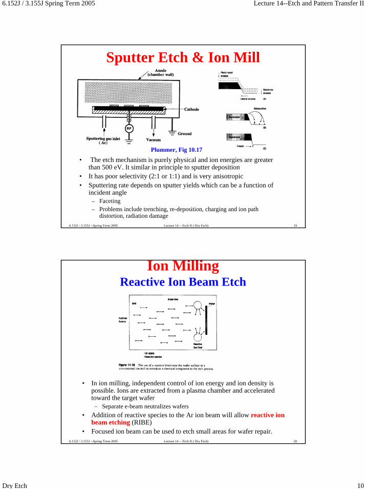
Sputter Etch & Ion Mill
• The etch mechanism is purely physical and ion energies are greater than 500 eV. It similar in principle to sputter deposition
• It has poor selectivity (2:1 or 1:1) and is very anisotropic• Sputtering rate depends on sputter yields which can be a function of
incident angle– Faceting– Problems include trenching, re-deposition, charging and ion path
distortion, radiation damage
Plummer, Fig 10.17
6.152J / 3.155J --Spring Term 2005 Lecture 14 -- Etch II ( Dry Etch) 20
Ion MillingReactive Ion Beam Etch
• In ion milling, independent control of ion energy and ion density is possible. Ions are extracted from a plasma chamber and accelerated toward the target wafer
– Separate e-beam neutralizes wafers• Addition of reactive species to the Ar ion beam will allow reactive ion
beam etching (RIBE)• Focused ion beam can be used to etch small areas for wafer repair.

6.152J / 3.155J Spring Term 2005 Lecture 14--Etch and Pattern Transfer II
Dry Etch 11
6.152J / 3.155J --Spring Term 2005 Lecture 14 -- Etch II ( Dry Etch) 21
Summary of Plasma Mechanisms
Plummer, Fig 10.19
Plummer, Fig 10.20
6.152J / 3.155J --Spring Term 2005 Lecture 14 -- Etch II ( Dry Etch) 22
Plasma Etch Methods for Various Films• Most reactant gasses contain halogens
– Cl, F, Br, or I• Exact choice of reactant gasses to etch each specific film depends on
– Ability to form volatile by-products– Etch selectivity to resist and underlying films– Anisotropicity
• Boiling points are good indicators of volatility of species– Lower boiling point, higher tendency to evaporate
TiF4

6.152J / 3.155J Spring Term 2005 Lecture 14--Etch and Pattern Transfer II
Dry Etch 12
6.152J / 3.155J --Spring Term 2005 Lecture 14 -- Etch II ( Dry Etch) 23
Typical Etch Chemistries
6.152J / 3.155J --Spring Term 2005 Lecture 14 -- Etch II ( Dry Etch) 24
Plasma EtchingSilicon Dioxide
Sidewall Spacer FormationSidewall Passivation

6.152J / 3.155J Spring Term 2005 Lecture 14--Etch and Pattern Transfer II
Dry Etch 13
6.152J / 3.155J --Spring Term 2005 Lecture 14 -- Etch II ( Dry Etch) 25
Poly-Silicon Etch
• Choice of chemistry depends on – Volatility of by-product– Selectivity over silicon dioxide– Anisotropicity– Ability to etch surface oxides
• Fluorine based chemistry (CF4, NF3 and SF6) tend to be isotropic because of lack of polymer formation
• When anisopicity is not important, SF6/O2 is a good chemistry because it enhances fluorine concentration and is selective to oxide
• When anisotropicity is desired from CF4 etches, start etch with CF4/H2and switch to CF4/O2 at the end– This will result in some undercutting
6.152J / 3.155J --Spring Term 2005 Lecture 14 -- Etch II ( Dry Etch) 26
Poly-Silicon Etch• Chlorine based chemistry (Cl2, HCL, SiCl4, BCl3) result in anisotropic
and selective etching of polysilicon– Etch rate increased by ion bombardment due to bond breaking or reaction
product removal– Can be anisotropic without polymer inhibitor formation– Selectivity to oxide is high (100:1)– Anisotropicity enhanced by adding small amount of O2– Etch rate slower than F chemistry
• Bromine based chemistry (HBr, Br2) are similar to chlorine based etching chemistry
– Anisotropic and selective to oxide without the need for a polymer inhibitor
– Slower than F or Cl– Adding O2 promotes inhibitor formation (forming SiO2 from Si and
removal of C from resist erosion• There may be a need to etch an initial break-through layer by adding
CF4 or the use of very high power

6.152J / 3.155J Spring Term 2005 Lecture 14--Etch and Pattern Transfer II
Dry Etch 14
6.152J / 3.155J --Spring Term 2005 Lecture 14 -- Etch II ( Dry Etch) 27
Aluminum Etch• Choice of chemistry depends on
– Volatility of by-product, Selectivity over silicon dioxide– Anisotropicity, Ability to etch surface oxides
• Presence of native oxide Al2O3 on Al surface requires a breakthrough etch before the main etch– Use Ar sputter– Use BCl3, SiCl4, CCl4 or BBr3 to scavenge O2 & H2O
• Cl2 etches Al isotropically• For anisortopic etching, sidewall inhibitor formation is needed
– CHCl3, CFCl3, CCl4
• Corrosion of the etched Al line occurs when exposed to ambient because Cl on sidewall and resist react with water to form HCl which etches Al
• Passivate Al surface after etch before exposure to atmosphere– Heat wafer to 100-150 C to drive-off Cl– Bury Cl with CHF3 polymer and wet etch the polymer later– Expose to F ambient such as SF6 plasma to replace Cl with F– O2 plasma followed by DI water rinse
6.152J / 3.155J --Spring Term 2005 Lecture 14 -- Etch II ( Dry Etch) 28
Picture Gallery
Aluminum EtchPlasma Etcher
Silicon EtchDeep RIE
SpoutsEmitter
Electrode Clip
Silicon EtchPlasma-Isotropic

6.152J / 3.155J Spring Term 2005 Lecture 14--Etch and Pattern Transfer II
Dry Etch 15
6.152J / 3.155J --Spring Term 2005 Lecture 14 -- Etch II ( Dry Etch) 29
Etch Picture GalleryOxide EtchRIE
Poly-silicon EtchRIE
Silicon EtchRIE
6.152J / 3.155J --Spring Term 2005 Lecture 14 -- Etch II ( Dry Etch) 30
Summary of Etch
• Etching is principally used to define patterns in VLSI and MEMs• Critical Parameters are
– Selectivity– Anisotropicity– Etch rate– Uniformity
• Etching occurs in three stages– Mass transport of etchant to surface– Reaction at surface– Mass transport of reaction product from surface
• Gas phase etching requires plasmas that work in the following modes– Chemical – isotropic and selective– Physical – anisotropic and non-selective– Ion enhanced – anisotropic and selective