etc lunch and learn presentation · 15 comparison chart there is no perfect touch technology! touch...
TRANSCRIPT

DELIVERING QUALITY SINCE 1952.
Touch PanelsCapabilities, Design, & Assembly
[4.5.13]

2
Agenda
Touch panels are the new interface standard Epec’s Touch Technologies
– Benefits– Applications– Sizes
Design/Engineering
Assembly/Integration
Summary

3
Resistive Touch Panels
Two transparent electrode layers (film/film or film/glass) are separated by very small transparent insulation spacers. Pressure from a finger or stylus brings the layers into contact. The result is a drop in voltage at the contact point. The change in voltage is detected by the controller.

4
Resistive Touch Panels
4-Wire– X/Y are separate layers. – Touch screen will not operated with
damaged top layer.
5-Wire– Bottom layer contains all the electrodes. – Top layer is probe.– Increased durability.
• Operates with scratched/cut top layer.

5
Resistive Touch Panels
Benefits– Lowest cost technology– Low power consumption– Pressure actuated.
• Finger, gloves and stylus.– Resistant to water and dust.
Limitations:– One Touch– Lower light transmission (78 - 82%)– Lower durability than other technologies
• 4-wire: 1 Million touches• 5-wire: 10 Million touches
Size Range: 2.8 - 21” (Diagonal)– Standard and custom sizes.

6
Surface Capacitive
A transparent electrode film is placed on glass substrate (under scratch resistant cover). A small voltage is applied to each corner, generating a uniform low voltage electrical field across the panel. The location of a touch is calculated by the change in the electrical current.

7
Surface Capacitive
Benefits– 90% light transmission– Unaffected by moisture, temperature and dust.– Works with finger and conductive stylus.– Over 100 Million actuations.
Limitations:– Single touch– Finger or conductive stylus only.– May require calibration (EMI)
Size Range: 5 - 24” (Diagonal)– Standard and custom sizes

8
Projected Capacitive (PCAP)
1 or 2 conductive layers form an X-Y array of lines to create a grid of electrodes. The X/Y intersections are scanned continuously.

9
Projected Capacitive (PCAP)
By apply voltage, a grid of capacitors is created. Bringing a finger close to the sensor changes the electrostatic field. The change at every point on the grid is measured to determine the location.

10
Projected Capacitive (PCAP)
Benefits– Glass top layer
• Scratch resistant– Multi-touch – recognizes two or more simultaneous touch points.
• 2- 10 multi-touches (dependent on controller)
– Touch coordinates are drift free.– Precise position location– Excellent optical clarity (90%+)– Zero-bezel design (flush surface)– Auto-calibration
Limitations– Gloved hand*– Higher cost
Size Range: 7 - 24” (Diagonal)

11
Controller– PCBA– Chipset– COF (Chip on flex)
Interface– USB– RS232– I2C
Drivers available for most operating systems including– Windows – Linux– Android
Touch Controllers/Interfaces

12
Design Considerations
What is the best solution for my product?
– Size– Environment– Application
• Aerospace, medical and military– Durability
• Number of touches• Surface hardness• Sealing
– Nema4 and IP65
– Input• Stylus, gloved hand, finger
– Cost

13
Touch Panel Integration
Mounting the touch panel to the display– Rear Mounting
– Front Mounting

14
Touch Panel Integration
General Guidelines– A. Bezel edge to active area - 1.00 mm (min)– B. Bezel edge to viewable area - .8mm (min)– C. Bezel face to touch screen - .3 - .7 mm– D. Gasket edge to viewable area – 1.00 (min)
• Spacing may need to increase due to gasket material.
Gasket material selection– NEMA 4 and IP65 standards

15
Comparison Chart
There is no perfect touch technology!
TOUCH TECHNOLOGY
Resisitive Surface
CapacitiveProjected Capacitive Infrared
Size 2.8 ‐ 21" 5 ‐ 24" 7 ‐ 24" 15 ‐ 46"Touch Accuracy Good Good Excellent GoodOperating Force 50g ‐ 100g 0g 0g 0gLight Transmission Poor/Good Very good Excellent ExcellentCalibration Stability Poor/Good Poor Good ExcellentTouch Life 1 ‐ 10 Million 100 Million Unlimited UnlimitedGloved Hand Yes No Yes YesStylus Yes Cond. Stylus Cond. Stylus YesSealing Nema 4/IP65 Nema 4/IP65 Nema 4/IP65 Nema 4/IP65Multi‐touch No* No Yes NoOperating Temp (10) ‐70°C* (20) ‐70°C (10) ‐70°C (20) ‐70°CHumidity Good Excellent Excellent ExcellentSurface Moisture Unaffected Unaffected Unaffected AffectedSurace Contaminants Unaffected Unaffected Unaffected Affected

16
Summary
Multiple touch technologies.– Epec’s technology offerings cover over 90% of the touch units sold.
Standard and custom sizes.– Engineering documentation is available for standard sizes.
Design support from concept through production.– Reverse engineering
17
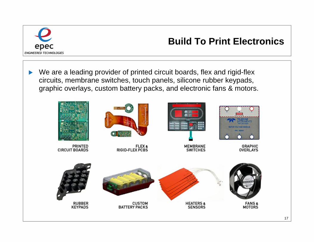
Build To Print Electronics
We are a leading provider of printed circuit boards, flex and rigid-flex circuits, membrane switches, touch panels, silicone rubber keypads, graphic overlays, custom battery packs, and electronic fans & motors.

18
Thank You
If you require additional information please contact us with any questions or requests.
North American Headquarters174 Duchaine Blvd.New Bedford, MA 02745Tel: (508) 996-7400Fax: (508) 998-8694
Contact Us By Email:Sales [email protected] [email protected] [email protected]
Visit Our Website For More Informationwww.epectec.com
Stay Connected with Epec Engineered TechnologiesJoin our Social Community and keep in touch with all our latest technology investments, current news, upcoming events, and promotions. Visit our Social Media Websites for more information.