et 200m signal modules for process automation...signal modules for process automation configuration...
TRANSCRIPT

Preface
Overview 1
Project Engineering 2
Configuring 3
Parameter Assignment 4
Diagnostics 5
Specifications 6
Appendix A
SIMATIC
ET 200M Signal Modules for Process Automation
Configuration Manual
Edition 10/2004 A5E00085262-04
This manual is part of the documentation package with the order number: 6ES7153-1AA00-8BA0
The following supplements are part of this documentation:
No. Designation Drawing number Edition 1 Product information A5E00201782-03 12/2004

Safety Guidelines This manual contains notices which you should observe to ensure your own personal safety as well as to avoid property damage. The notices referring to your personal safety are highlighted in the manual by a safety alert symbol, notices referring to property damage only have no safety alert symbol.
Danger
indicates an imminently hazardous situation which, if not avoided, will result in death or serious injury.
Warning
indicates a potentially hazardous situation which, if not avoided, could result in death or serious injury.
Caution
used with the safety alert symbol indicates a potentially hazardous situation which, if not avoided, may result in minor or moderate injury.
Caution
used without safety alert symbol indicates a potentially hazardous situation which, if not avoided, may result in property damage.
Notice
used without the safety alert symbol indicates a potential situation which, if not avoided, may result in an undesirable result or state.
When several danger levels apply, the notices of the highest level (lower number) are always displayed. If a notice refers to personal damages with the safety alert symbol, then another notice may be added warning of property damage.
Qualified Personnel The device/system may only be set up and operated in conjunction with this documentation. Only qualified personnel should be allowed to install and work on the equipment. Qualified persons are defined as persons who are authorized to commission, to earth, and to tag circuits, equipment and systems in accordance with established safety practices and standards.
Intended Use Please note the following:
Warning
This device and its components may only be used for the applications described in the catalog or technical description, and only in connection with devices or components from other manufacturers approved or recommended by Siemens.
This product can only function correctly and safely if it is transported, stored, set up and installed correctly, and operated and maintained as recommended.
Trademarks All designations marked with ® are registered trademarks of Siemens AG. Other designations in this documentation might be trademarks which, if used by third parties for their purposes, might infringe upon the rights of the proprietors.
Copyright Siemens AG, 2004. All rights reserved Reproduction, transmission or use of this document or its contents is not permitted without express written authority. Offenders will be liable for damages. All rights, including rights created by patent grant or registration of a utility model or design, are reserved.
Disclaimer of Liability We have checked the contents of this manual for agreement with the hardware and software described. Since deviations cannot be precluded entirely, we cannot guarantee full agreement. However, the data in the manual are reviewed regularly, and any necessary corrections will be included in subsequent editions. Suggestions for improvement are welcomed.
Siemens AG Automation and Drives Group P.O. Box 4848, D-90327 Nuremberg (Germany)
Siemens AG 2004 Technical data subject to change
Siemens Aktiengesellschaft A5E00085262-04

Signal Modules for Process Automation Configuration Manual, Edition 10/2004, A5E00085262-04 iii
Preface
Purpose of the Documentation This documentation provides you with support in using the signal modules for process automation. You will find all the information you require on using the modules in the PCS 7 process control system.
Target group This documentation is aimed at those who want to install and use the modules described in an ET 200M and in the PCS 7 process control system.
Required Basic Knowledge You need knowledge in the field of automation engineering to understand the documentation.
Validity of the Documentation The manual is valid for the following modules:
• 6ES7321-7TH00-0AB0
• 6ES7322-8BH00-0AB0
• 6ES7322-8BH01-0AB0
Changes in Comparison to the Previous Version In comparison to the previous version, we have reorganized the document and integrated the product information for 6ES7322-8BH01-0AB0 into the document.

Preface
Signal Modules for Process Automation iv Configuration Manual, Edition 10/2004, A5E00085262-04
Position in the Information Landscape This manual is a component of the product package with the order number 6ES7153-1AA00-8AA0. The product package consists of the following manuals and their respective contents:
Manual ET 200M Distributed I/O System
Manual S7-300 Module Data
This manual ET 200M Distributed I/O Device, Signal Modules for Process Automation
• Mechanical Configuration • Installation and Wiring
• General Technical Specifications • Power Supply Modules • Digital Modules • Analog Modules • RS 485 Repeater • SIMATIC TOP Connect
• Overview of Usage in Process Automation
• Parameter Assignment with SIMATIC PDM
• Digital Modules
Electronic Manual You will also find the manual in the SIMATIC Manual Collection (order number 6ES7998-8XC01-8YE0).
Organization of the Documentation To help you find specific information quickly, the manual contains the following navigation aids: • A comprehensive table of contents and a list of tables which are always provided at the
beginning of the manual. • A heading indicating the contents of each section is provided in the left-hand column on
each page of each chapter. • Following the chapters, you will find a glossary in which important technical terms used in
the manual are defined. • At the end of the manual you will find a detailed index which makes it easy for you to find
the information you are looking for.
Special Notes Some values in the technical specifications are specified with attributes. These attributes of the values of the technical specifications have the following meanings:
Attribute Meaning Minimum/ maximum A minimum/maximum value represents the limit or operating value
guaranteed by Siemens. This value must not be violated during operation within other limits.
Typical The typical value is found under nominal conditions and an ambient temperature of 25° C. Component tolerances allow values above and below the typical values.
Approx. The "approx." value is a value that has been rounded up or down (the weight of a module, for example).
Without attribute Values without an attribute are nominal values, not values subject to tolerance.
Recycling and Disposal The materials used in the signal modules for process automation can be recycled. Contact a certified disposal company for electronic refuse for recycling and disposal of your old equipment in an environmentally-friendly manner.

Signal Modules for Process Automation Configuration Manual, Edition 10/2004, A5E00085262-04 v
Table of contents Preface ...................................................................................................................................................... iii
1 Overview................................................................................................................................................. 1-1
1.1 Product Overview....................................................................................................................... 1-1
1.2 Used together with other products............................................................................................. 1-2
2 Project Engineering ................................................................................................................................ 2-1
3 Configuring ............................................................................................................................................. 3-1
4 Parameter Assignment ........................................................................................................................... 4-1
4.1 Parameter Assignment .............................................................................................................. 4-1
4.2 Reconfiguration during runtime.................................................................................................. 4-3
5 Diagnostics ............................................................................................................................................. 5-1
5.1 Diagnostics Using the Process Image of Inputs ........................................................................ 5-1
5.2 Diagnostic data .......................................................................................................................... 5-2
6 Specifications ......................................................................................................................................... 6-1
6.1 General technical specifications ................................................................................................ 6-1
6.2 Digital input module SM 321; DI 16 x NAMUR .......................................................................... 6-2 6.2.1 Specifications............................................................................................................................. 6-2 6.2.2 Parameter .................................................................................................................................. 6-6 6.2.2.1 Parameters of the digital input module ...................................................................................... 6-6 6.2.2.2 Flutter monitoring ....................................................................................................................... 6-7 6.2.2.3 Pulse stretching.......................................................................................................................... 6-9 6.2.2.4 Identification Data .................................................................................................................... 6-10 6.2.3 Sensor...................................................................................................................................... 6-11 6.2.3.1 Connection Guideline for Sensors ........................................................................................... 6-11 6.2.3.2 Terminal Assignment Diagrams............................................................................................... 6-15 6.2.4 Diagnostics of the Digital Input Module ................................................................................... 6-19 6.2.4.1 Diagnostics of the Digital Input Module ................................................................................... 6-19 6.2.4.2 Diagnostics Based on the Sensor............................................................................................ 6-20 6.2.4.3 Diagnosis with sensor changeover contact ............................................................................. 6-21
6.3 Digital output module SM 322; DO 16 x DC 24 V/ 0.5 A ......................................................... 6-23 6.3.1 Specifications........................................................................................................................... 6-23 6.3.2 Tips and notes about the SM 322 with order number 6ES7 322-8BH01-0AB0 ...................... 6-28 6.3.3 Parameters of the digital output module .................................................................................. 6-29 6.3.4 Diagnostics of the Digital Output Module................................................................................. 6-31

Table of contents
Signal Modules for Process Automation vi Configuration Manual, Edition 10/2004, A5E00085262-04
A Appendix.................................................................................................................................................A-1
A.1 Dimension drawing.....................................................................................................................A-1
A.2 Service and Support...................................................................................................................A-2
Glossary ..................................................................................................................................... Glossary-1
Index................................................................................................................................................ Index-1
Tables
Table 2-1 Software requirements for configuration .................................................................................... 2-3 Table 3-1 Configuring................................................................................................................................. 3-1 Table 3-2 DDB File in STEP 7 / COM PROFIBUS..................................................................................... 3-2 Table 4-1 Parameter Assignment............................................................................................................... 4-1 Table 4-2 Changing the parameter assignment......................................................................................... 4-3 Table 6-1 Technical specifications SM 321 DI 16xNAMUR....................................................................... 6-4 Table 6-2 Parameters of the digital input module ...................................................................................... 6-6 Table 6-3 Identification data of the digital input module............................................................................. 6-7 Table 6-4 Overview of identification data ................................................................................................. 6-10 Table 6-5 Performance factors for BEROs and sensors.......................................................................... 6-13 Table 6-6 Rules on the sensor load ......................................................................................................... 6-13 Table 6-7 Example for sensor load .......................................................................................................... 6-14 Table 6-8 Diagnostic messages of the digital input module, causes and remedies ................................ 6-19 Table 6-9 Diagnostics depending on sensor............................................................................................ 6-20 Table 6-10 Diagnostics with changeover contact sensor........................................................................... 6-22 Table 6-11 Specifications SM 322; DO 16x DC24V/0.5A .......................................................................... 6-26 Table 6-12 Parameters of the digital output module .................................................................................. 6-29 Table 6-13 Identification data of the digital output module ........................................................................ 6-30 Table 6-14 Diagnostic messages of the digital output module, causes and remedies .............................. 6-31 Table 6-15 Diagnostic messages of the digital output module, causes and remedies .............................. 6-32

Signal Modules for Process Automation Configuration Manual, Edition 10/2004, A5E00085262-04 1-1
Overview 11.1 Product Overview
Signal Modules for Process Automation Signal modules for process automation are part of the S7-300 I/O module range which offers functions in addition to those of "standard" I/O modules:
• Technological functions
– Pulse stretching
– Flutter monitoring
• Enhanced diagnostics
• Provision of identification data
You can make full use of these additional functions in an ET 200M which is used in the PCS 7 process control system.
Declaration The "signal modules for process automation" are referred to below as "process control modules".

Overview 1.2 Used together with other products
Signal Modules for Process Automation 1-2 Configuration Manual, Edition 10/2004, A5E00085262-04
1.2 Used together with other products
Hardware Requirements You will require the IM 153-2 as a DP slave interface as of the following version
IM 153 Order number IM 153-2 as of 6ES7 153-2AA02-0XB0, Version 07 IM 153-2 FO as of 6ES7 153-2AB01-0XB0, Version 06
In a central configuration, you can also use the process control module central in an S7-300 with the following CPUs:
CPU Order number CPU 312C as of 6ES7 312-5BD01-0AB0 CPU 312 as of 6ES7 312-1AD10-0AB0 CPU 313C as of 6ES7 313-5BE01-0AB0 CPU 313C-2 PtP as of 6ES7 313-6BE01-0AB0 CPU 313C-2 DP as of 6ES7 313-6CE01-0AB0 CPU 314C-2 PtP as of 6ES7 314-6BF01-0AB0 CPU 314C-2 DP as of 6ES7 314-6CF01-0AB0 CPU 314 as of 6ES7 314-1AF10-0AB0 CPU 315-2 DP as of 6ES7 315-2AG10-0AB0
Software Requirements You will require the following to configure and assign parameters to the process control modules:
• STEP 7 as of V5.1 (SP1 or SP2) and SIMATIC PDM as of V5.1
• STEP 7 as of V5.1 SP3 (without SIMATIC PDM)
• PCS 7 as of V5.1 or V5.2/V5.2 SP1 and SIMATIC PDM as of V5.1
• PCS 7 V5.2 SP2 (without SIMATIC PDM)
• COM PROFIBUS as of V3.0 and SIMATIC PDM as of V5.1
• For use in third-party systems: Configuration software for the DP master and SIMATIC PDM as of V 5.1

Overview 1.2 Used together with other products
Signal Modules for Process Automation Configuration Manual, Edition 10/2004, A5E00085262-04 1-3
Note When using STEP 7 as of V5.1 SP3 and PCS 7 V 5.2 SP2, you must configure the modules of the process control system with STEP 7 in HW Config.
When using later versions of STEP 7, configuration is done with SIMATIC PDM as of V5.1. The subsequent chapter, in which the configuration with SIMATIC PDM is described, refers only to the STEP 7 Versions of V5.1 SP1 and 2 as well as PCS 7 V5.1, V5.2, V5.2 SP1.
After upgrading to STEP 7 V5.1 SP3 or PCS 7 SP2, you must reassign module parameters to process control modules already installed with STEP 7 (HW Config). You will then no longer be able to use the identification and information functions of the process control modules.
Identification Data You can also access the identification data of the module with STEP 7 as of V5.2.
Upgrading from STEP 7 V5.1 without SP3 to STEP 7 V5.1 SP3 As of STEP 7 V5.1 SP3, parameters are assigned exclusively in HW Config.
The use of PDM is not allowed as soon as STEP 7 V 5.1 SP3 is installed on your engineering system.
If you have configured your modules with PDM until now, proceed as follows:
1. The modules should not be deleted in the configuration so that the I/O addresses and symbols are retained.
If you delete and reconfigure the modules, the I/O addresses may be reassigned and the symbols are to be remodified.
2. Reconfigure all the channels of the modules in HW Config.
3. Download the configuration to the PLC.

Overview 1.2 Used together with other products
Signal Modules for Process Automation 1-4 Configuration Manual, Edition 10/2004, A5E00085262-04
Integration in the Process Control System The following section applies to STEP 7 V 5.1 SP 1 and SP2 as well as for PCS 7 V 5.1, V 5.2, V5.2 SP 1.
PCS 7 is a powerful process control system. With PCS 7 and the process control modules, the ET 200M has a direct connection to the process control system. This is also evident from the following:
• Configuration of the process control modules with SIMATIC PDM (add-on package for STEP 7)
• The evaluation and continued processing of the input/output signals is performed by PCS 7 driver blocks in the DP master CPU.
S7-400
Figure 1-1 Integration in the process control system
Information about the PCS 7 Process Control System You can find more detailed information on the PCS 7 process control system in the PCS 7documentation.

Signal Modules for Process Automation Configuration Manual, Edition 10/2004, A5E00085262-04 2-1
Project Engineering 2Operating principle for configuration
The following section applies to STEP 7 V 5.1 SP 1 and SP2 as well as for PCS 7 V 5.1, V 5.2, V5.2 SP 1
321
S7-400
Figure 2-1 Operating principle for configuration
Number Meaning 1 Cyclic data
communication: • User data input/outputs and value status
2 Cyclic data communication:
• Configuration and bus parameters for network configuration (network configuration, for example) Diagnostic interrupts (only with S7, DP V1)
3 Cyclic data communication:
• Parameters of the process control modules • Informational data of the process control modules

Project Engineering
Signal Modules for Process Automation 2-2 Configuration Manual, Edition 10/2004, A5E00085262-04
Configuration This step involves configuring and assigning parameters to the ET 200M using the programming device.
Configuring You configure the ET 200M with STEP 7 / COM PROFIBUS or with appropriate configuration software. At configuration, you only set the basic features of the DP slave (the network parameters, for example).
Parameter Assignment You assign parameters to the ET 200M and the inserted modules:
• You assign parameters to the ET 200M and "standard" I/O modules with STEP 7.
• You assign parameters to the process control modules with SIMATIC PDM.
Cyclic Data Communcation via PROFIBUS DP Cyclic data communication takes place between the CPU (S7-400, for example) and the ET 200M. The following data is transferred:
• The cyclic user data of the inputs and outputs, including the value status of inputs
• The diagnostic interrupts
This data is prepared in the CPU by the PCS 7 driver and the CFC (Continuous Function Chart) for system visualization. This data is then presented on the OS by means of WINCC.
The parameters (for network configuration, for example) are also transferred cyclically.
Acyclic Data Communication via PROFIBUS DP Acyclic data communication takes place between the process control modules of the ET 200M and the programming device/PC (SIMATIC PDM). The process control modules of the ET 200M are assigned parameters using this acyclic data communication. Informational data is also transferred and displayed in SIMATIC PDM .
• Diagnostics and Interrupts
• Data records (only with S7)
Project Engineering
Signal Modules for Process Automation Configuration Manual, Edition 10/2004, A5E00085262-04 2-3
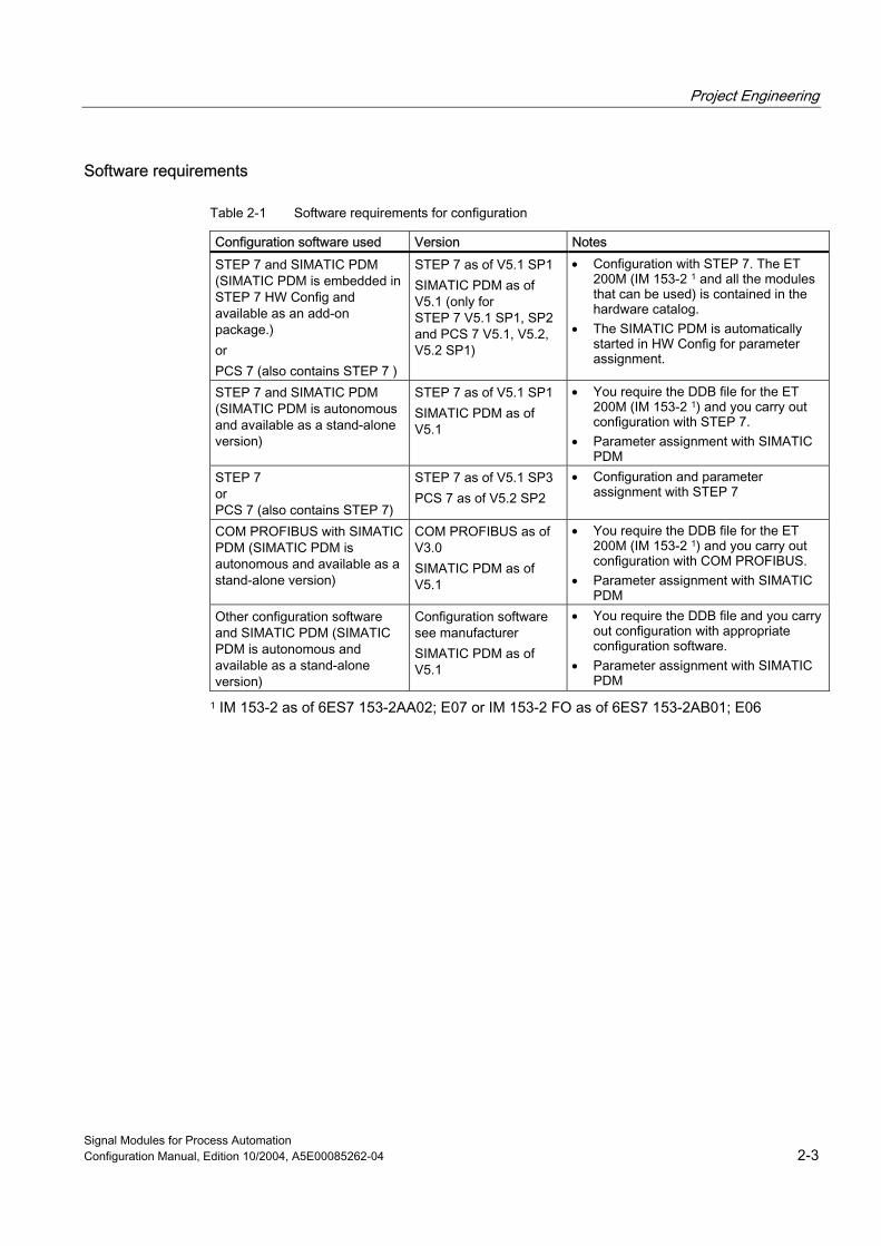
Software requirements
Table 2-1 Software requirements for configuration
Configuration software used Version Notes STEP 7 and SIMATIC PDM (SIMATIC PDM is embedded in STEP 7 HW Config and available as an add-on package.) or PCS 7 (also contains STEP 7 )
STEP 7 as of V5.1 SP1 SIMATIC PDM as of V5.1 (only for STEP 7 V5.1 SP1, SP2 and PCS 7 V5.1, V5.2, V5.2 SP1)
• Configuration with STEP 7. The ET 200M (IM 153-2 1 and all the modules that can be used) is contained in the hardware catalog.
• The SIMATIC PDM is automatically started in HW Config for parameter assignment.
STEP 7 and SIMATIC PDM (SIMATIC PDM is autonomous and available as a stand-alone version)
STEP 7 as of V5.1 SP1 SIMATIC PDM as of V5.1
• You require the DDB file for the ET 200M (IM 153-2 1) and you carry out configuration with STEP 7.
• Parameter assignment with SIMATIC PDM
STEP 7 or PCS 7 (also contains STEP 7)
STEP 7 as of V5.1 SP3 PCS 7 as of V5.2 SP2
• Configuration and parameter assignment with STEP 7
COM PROFIBUS with SIMATIC PDM (SIMATIC PDM is autonomous and available as a stand-alone version)
COM PROFIBUS as of V3.0 SIMATIC PDM as of V5.1
• You require the DDB file for the ET 200M (IM 153-2 1) and you carry out configuration with COM PROFIBUS.
• Parameter assignment with SIMATIC PDM
Other configuration software and SIMATIC PDM (SIMATIC PDM is autonomous and available as a stand-alone version)
Configuration software see manufacturer SIMATIC PDM as of V5.1
• You require the DDB file and you carry out configuration with appropriate configuration software.
• Parameter assignment with SIMATIC PDM
1 IM 153-2 as of 6ES7 153-2AA02; E07 or IM 153-2 FO as of 6ES7 153-2AB01; E06

Project Engineering
Signal Modules for Process Automation 2-4 Configuration Manual, Edition 10/2004, A5E00085262-04

Signal Modules for Process Automation Configuration Manual, Edition 10/2004, A5E00085262-04 3-1
Configuring 3Requirements
The information in this section applies to:
• IM 153-2 as of 6ES7 153-2AA02-0XB0, Version 07
• IM 153-2 FO as of 6ES7 153-2AB01-0XB0, Version 06
Configuring The table below describes the most important configuration steps:
Table 3-1 Configuring
STEP 7 as of V5.1 SP1 or PCS 7 as of V5.1
STEP 7 as of V5.1 COM PROFIBUS as of V3.0 / other configuration software
Features • The ET 200M (IM 153-2) is contained in the STEP 7 hardware catalog
• Diagnostic interrupts and time stamping are supported
• The ET 200M is integrated as an S7 DP slave
• You require the DDB file of the IM 153-2 • The ET 200M is integrated as a DP standard slave
Procedure 1. Start the SIMATIC Manager.
2. Configure the ET 200M with HW Config. – Create a new project. – Drag the modules from the
hardware catalog to the configuration table.
3. Save the configuration and download it to the DP master.
1. Start the SIMATIC Manager.
2. Integrate the DDB file in HW Config.
3. Configure the ET 200M with HW Config. – Create a new project. – Drag the modules from
the hardware catalog to the configuration table.
4. Save the configuration and download it to the DP master.
1. Start COM PROFIBUS / configuration software.
2. Integrate the DDB file in COM PROFIBUS / configuration software.
3. Configure the ET 200M with COM PROFIBUS / configuration software.
4. Save the configuration and download it to the DP master.
Configuration Information You can find additional information about configuration in the STEP 7 / COMPROFIBUS online help system.

Configuring
Signal Modules for Process Automation 3-2 Configuration Manual, Edition 10/2004, A5E00085262-04
DDB File in STEP 7 / COM PROFIBUS The table below describes how to integrate the DDB file in SIMATIC S7 or SIMATIC S5 (COM PROFIBUS).
Table 3-2 DDB File in STEP 7 / COM PROFIBUS
STEP7 COM PROFIBUS as of V 3.0
1. Start STEP 7 and select the menu command Options / Install New DDB File.
2. Select the DDB file to be installed in the subsequent dialog box and confirm with OK.
Result: The field device is displayed in the hardware catalog in the PROFIBUS-DP directory.
1. Copy the DDB file from ET 200M (IM 153-2) into the COM PROFIBUS directory: ...COMPB3\GSD (default) Copy the Bitmap file into the directory: ...COMPB3\BITMAPSStart COM PROFIBUS and call the menu command File / Download GSD file.
Result: The ET 200M (IM 153-2) is displayed in the hardware catalog during slave configuration
Downloading the GSD File You can download the GSD file for the ET 200M (IM 153-2) as follows:
• in the Internet at the address: www.ad.siemens.de/csi_e/gsd
• via modem with the telephone number +49 (911) 73 79 72

Signal Modules for Process Automation Configuration Manual, Edition 10/2004, A5E00085262-04 4-1
Parameter Assignment 44.1 Parameter Assignment
Requirements The information in this section applies to:
• IM 153-2 as of 6ES7 153-2AA02-0XB0, Version 07
• IM 153-2 FO as of 6ES7 153-2AB01-0XB0, Version 06
Procedure The following table describes the most important steps for assigning parameters to process control modules:
Table 4-1 Parameter Assignment
STEP 7 (as of V5.1 SP1 and SP2 ) with the SIMATIC PDM optional package (as of V5.1) or PCS 7 (as of V5.1, V5.2, V5.2 SP1)
SIMATIC PDM as of V5.1
Features You assign parameters to the process control modules in the ET 200M. Requirements
SIMATIC PDM is already installed on the programming device/PC or PCS 7 ES.
SIMATIC PDM must be a stand-alone version
Procedure
1. You are still in HW Config. Double-click the first process control module in the configuration table. Result: SIMATIC PDM is started.
2. Set the parameters of the process control module with SIMATIC PDM.
3. In HW Config, double-click the next process control module in the configuration table.
4. Set the parameters of the process control module with SIMATIC PDM.
5. Repeat steps 3 and 4 until you have set all the parameters of the process control modules.
6. Save the parameters or, if you are online, download the parameters to the process control modules.
1. Start SIMATIC PDM.
2. Configure a point-to-point connection for the ET 200M.
3. Set the parameters for all the process control modules of the ET 200M with SIMATIC PDM.
4. Save the parameters or, if you are online, download the parameters to the ET 200M.

Parameter Assignment 4.1 Parameter Assignment
Signal Modules for Process Automation 4-2 Configuration Manual, Edition 10/2004, A5E00085262-04
Note Set the parameters with STEP 7 when using SIMATIC S7 or PCS 7. Set the parameters with SIMATIC PDM when using a DP standard master.
Startup Response The modules have to be reconfigured if they are unplugged and plugged in again. Evaluate the unplugged/plugged interrupt in the user program for this purpose.
If a process control module is to operate with default parameters and if a bumpless module replacement is required in a plant, the new module has to be set to the default parameters beforehand.
The default parameter configuration activates the retentively stored parameters in the process control modules.
Note This procedure also applies when no parameters are set in STEP 7.
Parameter Assignment Information You can find additional information about parameter assignment in the SIMATIC PDM documentation.

Parameter Assignment 4.2 Reconfiguration during runtime
Signal Modules for Process Automation Configuration Manual, Edition 10/2004, A5E00085262-04 4-3
4.2 Reconfiguration during runtime
Procedure The following table describes the most important steps when changing the parameter assignment of the process control modules:
Table 4-2 Changing the parameter assignment
STEP 7 (as of V5.1 SP1 and SP2 ) with the SIMATIC PDM optional package (as of V5.1) or PCS 7 as of V5.1, V5.2, V5.2 SP1
SIMATIC PDM as of V5.1
Features You can reconfigure the process control modules during runtime (only with SIMATIC PDM). Requirements
SIMATIC PDM is already integrated on the programming device/PC or PCS 7 ES.
SIMATIC PDM must be a stand-alone version
Procedure 1. Start the STEP 7 SIMATIC Manager
2. Open the project in which you configured the ET 200M.
3. Double-click the process control module in HW Config in the configuration table you want to reconfigure. Result: SIMATIC PDM is started.
4. Download the parameters/identification data of the process control module to the programming device/PC.
5. Change the parameters/identification data.
6. Download the parameters/identification data to the process control module.
7. Check: Download the parameters/identification data of the process control module again to the programming device/PC and check the new configuration.
1. Start SIMATIC PDM.
2. Configure a point-to-point connection for the ET 200M.
3. Download the parameters/identification data of the process control module to the programming device/PC.
4. Change the parameters/identification data.
5. Download the parameters/identification data to the process control module.
6. Check: Download the parameters/identification data of the process control module again to the programming device/PC and check the new configuration.
Parameter Assignment Information You can find additional information about parameter assignment in the SIMATIC PDM documentation.

Parameter Assignment 4.2 Reconfiguration during runtime
Signal Modules for Process Automation 4-4 Configuration Manual, Edition 10/2004, A5E00085262-04
Signal Modules for Process Automation Configuration Manual, Edition 10/2004, A5E00085262-04 5-1
Diagnostics 55.1 Diagnostics Using the Process Image of Inputs
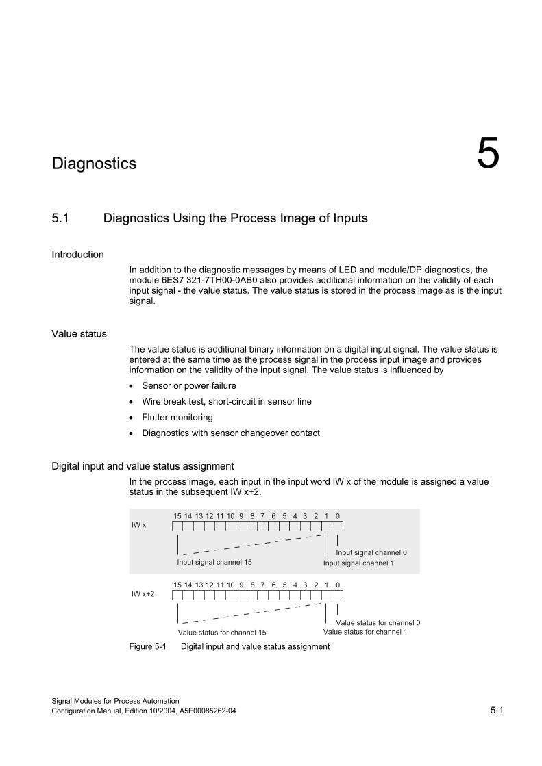
Introduction In addition to the diagnostic messages by means of LED and module/DP diagnostics, the module 6ES7 321-7TH00-0AB0 also provides additional information on the validity of each input signal - the value status. The value status is stored in the process image as is the input signal.
Value status The value status is additional binary information on a digital input signal. The value status is entered at the same time as the process signal in the process input image and provides information on the validity of the input signal. The value status is influenced by
• Sensor or power failure
• Wire break test, short-circuit in sensor line
• Flutter monitoring
• Diagnostics with sensor changeover contact
Digital input and value status assignment In the process image, each input in the input word IW x of the module is assigned a value status in the subsequent IW x+2.
Figure 5-1 Digital input and value status assignment

Diagnostics 5.2 Diagnostic data
Signal Modules for Process Automation 5-2 Configuration Manual, Edition 10/2004, A5E00085262-04
Meaning of value status The value status means:
• 0 = Signal invalid
• 1 = Signal valid
Evaluation of the Value Status in PCS 7 The value status is evaluated in your CFC program with block FC 277 "CH_DI: Digital Input". This module undertakes the processing of the digital input value of S7-300-Digital input modules.
How the value status gets into the block:
1. Link the symbol created with STEP 7 in the symbol table for the digital input channel with the VALUE input parameter.
2. Link the status symbol of the value of the digital input channel with the VALUE_QC input parameter
3. Set the PQC = TRUE input parameter
If you use the driver wizard in PCS 7 (as of V 5.1), steps 2 and 3 are executed automatically by PCS 7.
Information about FC 277 and Processing of the Input Signals You can find a detailed description of the block and how the input signals are processed in the PCS7 documentation.
5.2 Diagnostic data
Organization of the Diagnostic Data This chapter describes the organization of the diagnostic data in the system data. You need to be familiar with this organization if you want to evaluate the diagnostic data of the signal modules in the STEP 7 user program.
In PCS 7, the CFC diagnostic block carries out the evaluation of the diagnostic data automatically.
Further Sources You can find a detailed description of the principle behind the evaluation of the diagnostic data of the signal modules in the user program and a description of the SFCs you can use to do this in the System and Standard Functions reference manual.
Diagnostics 5.2 Diagnostic data
Signal Modules for Process Automation Configuration Manual, Edition 10/2004, A5E00085262-04 5-3
Data Records 0 and 1 of the System Data The diagnostic data of a module is contained in the data records 0 and 1 of the system data area.
• Data record 0 contains 4 bytes of diagnostic data which are the same for all modules and describe the current status of an S7-300/ET 200M.
• Data record 1 contains:
– 4 bytes of diagnostic data of data record 0 and
– the remaining bytes containing the module-specific diagnostic data
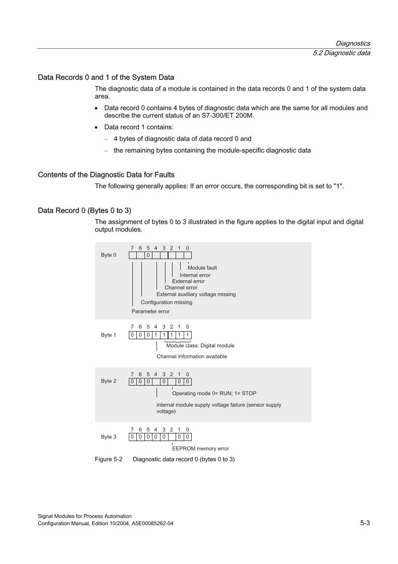
Contents of the Diagnostic Data for Faults The following generally applies: If an error occurs, the corresponding bit is set to "1".
Data Record 0 (Bytes 0 to 3) The assignment of bytes 0 to 3 illustrated in the figure applies to the digital input and digital output modules.
Figure 5-2 Diagnostic data record 0 (bytes 0 to 3)

Diagnostics 5.2 Diagnostic data
Signal Modules for Process Automation 5-4 Configuration Manual, Edition 10/2004, A5E00085262-04
Diagnostic data record 1 (as of byte 4) of the digital input module
Figure 5-3 Diagnostic data record 1 (as of byte 4) of the digital input module
Diagnostics 5.2 Diagnostic data
Signal Modules for Process Automation Configuration Manual, Edition 10/2004, A5E00085262-04 5-5
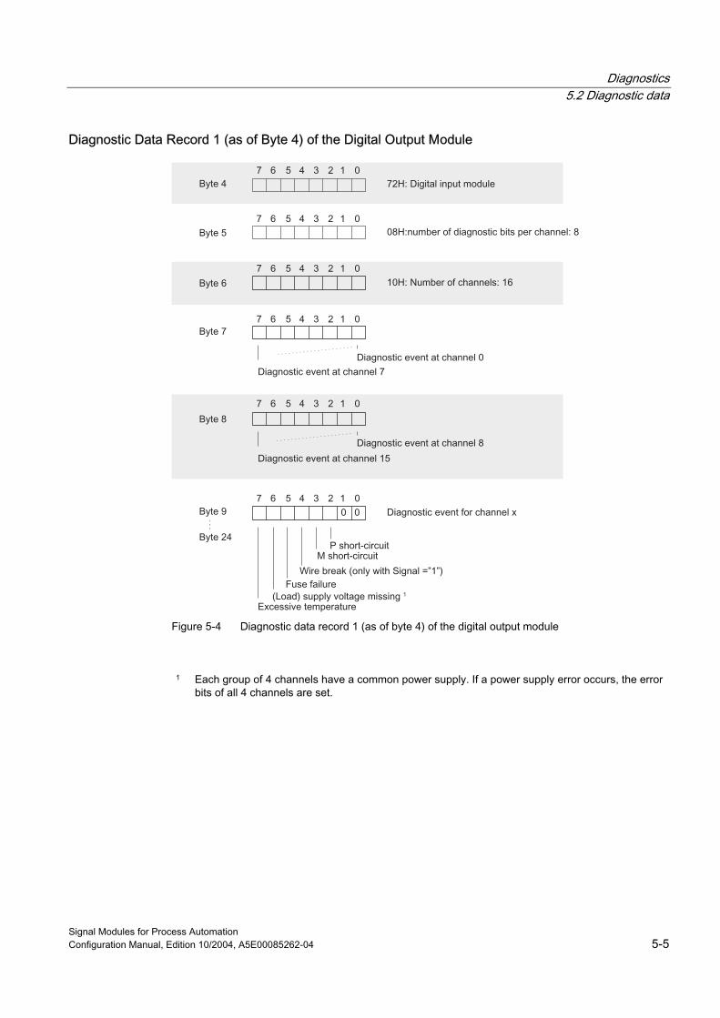
Diagnostic Data Record 1 (as of Byte 4) of the Digital Output Module
Figure 5-4 Diagnostic data record 1 (as of byte 4) of the digital output module
1 Each group of 4 channels have a common power supply. If a power supply error occurs, the error
bits of all 4 channels are set.

Diagnostics 5.2 Diagnostic data
Signal Modules for Process Automation 5-6 Configuration Manual, Edition 10/2004, A5E00085262-04

Signal Modules for Process Automation Configuration Manual, Edition 10/2004, A5E00085262-04 6-1
Specifications 66.1 General technical specifications
General Technical Specifications The general specifications of the process control modules for process automation correspond to the general specifications of the S7-300 modules.
These include, for example:
• Standards, certificates and approvals
• Electromagnetic compatibility
• Transport and storage conditions
• Mechanical and climatic ambient conditions
• Information on insulation testing, safety class and degree of protection
• Nominal voltages
General Specifications for S7-300 Modules. These can be found in the device manual, S7-300, Module Data.

Specifications 6.2 Digital input module SM 321; DI 16 x NAMUR
Signal Modules for Process Automation 6-2 Configuration Manual, Edition 10/2004, A5E00085262-04
6.2 Digital input module SM 321; DI 16 x NAMUR
6.2.1 Specifications
Order number 6ES7 321-7TH00-0AB0
Properties The SM 321; DI 16xNAMUR has the following features:
• 16 inputs
• Connection for a wide variety of sensor types
– NAMUR sensor according to NAMUR worksheet NA 01
• Process control functions
– Pulse stretching
– Flutter monitoring
• Value status
• Identification data
• Input nominal voltage 24 V DC
Inrush current The SM 321; DI 16xNAMUR has an inrush current of 4 A.
We recommend you power the digital input module with its own power supply. So that you can make sure that no neighboring modules will be affected when the digital input module (e.g. by inserting the front connector after a module replacement while the device is in operation) is turned on.

Specifications 6.2 Digital input module SM 321; DI 16 x NAMUR
Signal Modules for Process Automation Configuration Manual, Edition 10/2004, A5E00085262-04 6-3
Terminal Assignment and Block Diagram In the figure, NAMUR sensors are connected to the inputs as an example. You can find out how to connect the other possible sensors in the section on sensors.
Figure 6-1 Module view and block diagram of the SM 321; DI 16 x NAMUR
Number Meaning 1 Status LED - green
Error LED - red 2 Channel number
Numbers 0 to 7 on the right side correspond to channel numbers 8 to 15 3 Backplane bus connection

Specifications 6.2 Digital input module SM 321; DI 16 x NAMUR
Signal Modules for Process Automation 6-4 Configuration Manual, Edition 10/2004, A5E00085262-04
Specifications
Table 6-1 Technical specifications SM 321 DI 16xNAMUR
Specifications Dimensions and Weight Dimensions W x H x D (mm) 40 x 125 x 120 Weight Approx. 200 g Specifications for Specific Modules Number of inputs 16 Occupied address area • In the process-image input table 4 bytes Cable length • Unshielded Not permitted • Shielded Max. 200 m with 8.2 V sensor (1VS1/2)
Max. 400 m with 18 V sensor (2VS1/2) Voltages, Currents, Potentials Nominal load voltage L+ 24 V DC • Reverse polarity protection Yes Number of inputs that can be addressed simultaneously
• Horizontal mounting up to 60° C
16
• Vertical mounting up to 40° C
16
Isolation • Between channels and backplane bus Yes • Between the channels
In groups of Yes 8
• Between power supply and sensor power supply
Yes
Permissible potential difference • Between the various circuits 75 V DC,
60 V AC Insolation tested with 600 V DC Power consumption • From the backplane bus Max. 100 mA • From the load voltage L+ (no load) Typical 100 mA • Inrush current (transient) 4 A Power dissipation of the module Typical 11 W Status, Interrupts, Diagnostics Status LEDs • Inputs Green LED per channel • Sensor power supplies (Vs) Green LED per output (Vs) Interrupts • Diagnostic interrupt Parameters can be assigned Diagnostic functions Parameters can be assigned • Group error display Red LED (SF) • Channel error display Red LED per channel (F) • Diagnostic information readable Possible

Specifications 6.2 Digital input module SM 321; DI 16 x NAMUR
Signal Modules for Process Automation Configuration Manual, Edition 10/2004, A5E00085262-04 6-5
Specifications Sensor Power Supply Outputs Number of outputs 4 Output voltage • Loaded 1VS1: 18 V
1VS2: 8.2 V 2VS1: 18 V 2VS2: 8.2 V
Output current • Nominal value At 18 V: 190 mA
At 8.2 V: 60 mA • Permissible range Up to 60° C At 18 V: 0 to 110 mA
At 8.2 V: 0 to 60 mA Up to 40° C At 18 V: 0 to 190 mA
At 8.2 V: 0 to 60 mA Additional (redundant) supply Not permitted Short-circuit protection Yes, electronic Data for Selecting a Sensor Input voltage • Nominal value 18 V
8.2 V Input current for NAMUR sensor • At signal "1" 2.1 to 7 mA • At signal "0" 0.35 to 1.2 mA Input current for 10 kΩ / 47 kΩ connected contact • At signal "1" Typical 10 mA • At signal "0" 0.35 to 1.2 mA Input current for unconnected contact and 3 and 4-wire BEROs
• At signal "1" Typical 10 mA • Permitted bias current 0.5 mA Input delay • At "0" to "1" 2.5 to 3.5 ms • At "0" to "1" 2.5 to 3.5 ms Input characteristic curve To IEC 1131, type 2 Connection of 2-wire BERO Possible in accordance with NAMUR Time/frequency Internal processing time for • Interrupt and diagnostics processing Max. 2 ms (at default setting) Input delay • Tolerated switchover time for changeover
diagnostics 300 ms
Specifications 6.2 Digital input module SM 321; DI 16 x NAMUR
Signal Modules for Process Automation 6-6 Configuration Manual, Edition 10/2004, A5E00085262-04
6.2.2 Parameter
6.2.2.1 Parameters of the digital input module
Content of the Following Tables The following tables contain
• all parameters and
• the identification data of the digital input module.
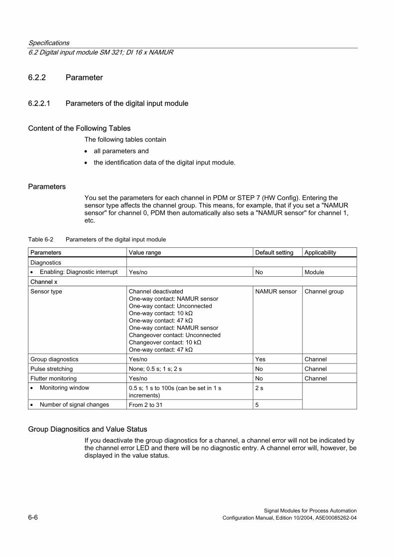
Parameters You set the parameters for each channel in PDM or STEP 7 (HW Config). Entering the sensor type affects the channel group. This means, for example, that if you set a "NAMUR sensor" for channel 0, PDM then automatically also sets a "NAMUR sensor" for channel 1, etc.
Table 6-2 Parameters of the digital input module
Parameters Value range Default setting Applicability Diagnostics • Enabling: Diagnostic interrupt Yes/no No Module Channel x Sensor type Channel deactivated
One-way contact: NAMUR sensor One-way contact: Unconnected One-way contact: 10 kΩ One-way contact: 47 kΩ One-way contact: NAMUR sensor Changeover contact: Unconnected Changeover contact: 10 kΩ One-way contact: 47 kΩ
NAMUR sensor Channel group
Group diagnostics Yes/no Yes Channel Pulse stretching None; 0.5 s; 1 s; 2 s No Channel Flutter monitoring Yes/no No Channel • Monitoring window 0.5 s; 1 s to 100s (can be set in 1 s
increments) 2 s
• Number of signal changes From 2 to 31 5
Group Diagnositics and Value Status If you deactivate the group diagnostics for a channel, a channel error will not be indicated by the channel error LED and there will be no diagnostic entry. A channel error will, however, be displayed in the value status.

Specifications 6.2 Digital input module SM 321; DI 16 x NAMUR
Signal Modules for Process Automation Configuration Manual, Edition 10/2004, A5E00085262-04 6-7
Identification Data
Table 6-3 Identification data of the digital input module
Identification Data Value range Default setting Applicability Device Manufacturer reading SIEMENS AG Module Device identification reading 6ES7 321-7TH00-0AB0 Module Device serial number reading Module Hardware revision reading Module Software revision reading
Depends on the version
Module Static revision no. reading – Module Installation date Read/write (max. 16 characters) – Module Operating unit TAG Read/write (max. 32 characters) – Module Description Read/write (max. 32 characters) – Module
Note Access to identification data is only possible with SIMATIC PDM.
Information about the Parameters You can find detailed information on the parameters for pulse lengthening, flutter monitoring and identification data in the following sections.
6.2.2.2 Flutter monitoring
What is Flutter Monitoring? Flutter monitoring is a process control function for digital input signals. It detects and reports unusual process control signal patterns such as a fluctuation in the input signal between"0" and "1"that occurs too often. The occurrence of such signal patterns indicates that the sensor is faulty or unstable.
Enabling Flutter Monitoring You enable flutter monitoring by means of the "Diagnostics: Flutter error".
Tip: Also enable the group diagnostics when assigning parameters so that if there is a flutter error, a diagnostic interrupt is also reported in addition to the diagnostic entry.

Specifications 6.2 Digital input module SM 321; DI 16 x NAMUR
Signal Modules for Process Automation 6-8 Configuration Manual, Edition 10/2004, A5E00085262-04
Detecting Unusual Signal Patterns A configurable monitoring window is available for each input channel. The monitoring window is started with the first change of the input signal. If the input signal changes more within the monitoring window than the configured number of signal changes, this is recognized as a flutter error. If a flutter error is not detected within the monitoring window, the monitoring window is started again at the next signal change.
Reporting a Flutter Error If a flutter error occurs, the current signal state is entered in the process image and the value status of the signal is set to "invalid". In addition, the "flutter error" is entered as diagnostic information and an incoming diagnostic interrupt is triggered.
You must evaluate and process the value status and the diagnostic information in the user program.
Resetting a Flutter Error If no further fluttering of the input signal is detected during the triple monitoring window, the diagnostic entry is removed and an outgoing diagnostic interrupt is triggered. The value status of the current signal in the process image is set to "valid".
Operating Principle The following figure illustrates the principle behind flutter monitoring.
Figure 6-2 Principle behind flutter monitoring
Settings for Flutter Monitoring You can find out which settings you can make for flutter monitoring in the parameter table and in the SIMATIC PDM online help.

Specifications 6.2 Digital input module SM 321; DI 16 x NAMUR
Signal Modules for Process Automation Configuration Manual, Edition 10/2004, A5E00085262-04 6-9
6.2.2.3 Pulse stretching
What is pulse stretching? Pulse stretching is a function for changing a digital input signal. A pulse at a digital input is extended to at least the configured length. If the input pulse is already longer than the configured length, it is not changed.
Principle Behind Pulse Stretching The following figure illustrates with examples if and how input pulses are changed.
T1 for 1 -> 0 edge
Figure 6-3 Principle behind pulse stretching
Figure 6-4 Example of pulse stretching
Specifications 6.2 Digital input module SM 321; DI 16 x NAMUR
Signal Modules for Process Automation 6-10 Configuration Manual, Edition 10/2004, A5E00085262-04
Note If you configure pulse stretching for an input channel, this also affects the flutter monitoring enabled for this channel. The "pulse-stretched" signal is the input signal for flutter monitoring. Make sure therefore that the parameters for pulse stretching and flutter monitoring correspond to each other. By selecting the appropriate values for the parameters, you can customize the functions to suit your process as well as possible.
Settings for Pulse Stretching You can find out which settings you can make for pulse stretching in the parameter table and in the SIMATIC PDM online help.
6.2.2.4 Identification Data
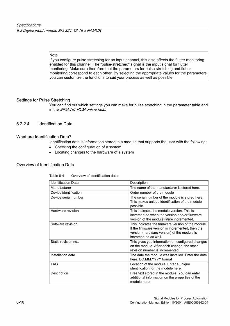
What are Identification Data? Identification data is information stored in a module that supports the user with the following: • Checking the configuration of a system • Locating changes to the hardware of a system
Overview of Identification Data
Table 6-4 Overview of identification data
Identification Data Description Manufacturer The name of the manufacturer is stored here. Device identification Order number of the module Device serial number The serial number of the module is stored here.
This makes unique identification of the module possible.
Hardware revision This indicates the module version. This is incremented when the version and/or firmware version of the module is/are incremented.
Software revision This indicates the firmware version of the module. If the firmware version is incremented, then the version (hardware version) of the module is incremented as well.
Static revision no.. This gives you information on configured changes on the module. After each change, the static revision number is incremented.
Installation date The date the module was installed. Enter the date here. DD.MM.YYYY format
TAG Location of the module. Enter a unique identification for the module here.
Description Free text stored in the module. You can enter additional information on the properties of the module here.

Specifications 6.2 Digital input module SM 321; DI 16 x NAMUR
Signal Modules for Process Automation Configuration Manual, Edition 10/2004, A5E00085262-04 6-11
6.2.3 Sensor
6.2.3.1 Connection Guideline for Sensors Because of the large number of sensors that can be connected to the digital input module, you must take the sensor load into account at configuration. You will find in this section:
• Recommendations on how to connect sensors
• An overview of the sensor-specific load
• A rule for the evaluation of the sensor-specific load
• An example
Sensors Can Be "Combined " You can connect a wide variety of sensors to the SM 321; DI 16xNAMUR and these can also be "combined".
When you assign parameters, you can specify which sensors are to be connected to which channel group. The same sensor type is assigned to the channels of a channel group.
Changeover Contacts Changeover contacts always occupy two adjacent inputs (for example, 0 and 1 or 2 and 3, etc.). Make sure you adhere to the following rule:
• Always connect the normally open contact to the "even" channel,
• Always connect the normally closed contact to "odd" channel.
2 Sensor Voltage Supplies: 18 V and 8.2 V The SM 321; DI 16xNAMUR has two different sensor supply voltages. The following table shows you which sensor to attach to which sensor supply:
18 V 8.2 V One-way contact or BERO connected to 10 kΩ/47 kΩ
NAMUR sensor or DIN 19234 sensor
Changeover contact or 4-wire BERO connected to 10 k/Ω47 kΩ
NAMUR sensor changeover contact or sensor DIN 19234 as changeover contact
One-way contact or 3-wire BERO unconnected Changeover contact or 4-wire BERO unconnected
Calculating the Performance Factor for the Use of a BERO We show you below which criteria a BERO should fulfill and how to calculate the performance factor in order to calculate the sensor load of the digital input module.

Specifications 6.2 Digital input module SM 321; DI 16 x NAMUR
Signal Modules for Process Automation 6-12 Configuration Manual, Edition 10/2004, A5E00085262-04
Technical Requirements for BERO The following figure illustrates the connections of a BERO and the most important characteristic quantities.
Figure 6-5 Connections and characteristic quantities of a BERO
Selection criteria:
• Operating voltage range (BERO terminal (+) and terminal (-)): 15 V to min. 20 V
• Transistor T1 functions as a switch (on/off)
• Protective measures:
– Spurious switch-on pulse suppressed
– Output A short circuit-proof
– Reverse polarity protection
– Wire break protection
– Anti-inductive protection
– Radio telephony protection
• Load capacity (T1) = 150 mA (at TA> 85° C)

Specifications 6.2 Digital input module SM 321; DI 16 x NAMUR
Signal Modules for Process Automation Configuration Manual, Edition 10/2004, A5E00085262-04 6-13
Performance Factors for BEROs from the "Low-Voltage Controlgear, Switchgear and Systems" Catalog
You will find a value in the table below that you can use to calculate the sensor load easily if:
• You use sensors from the "Low-Voltage Controlgear, Switchgear and Systems" NSK catalog from SIEMENS
• IC = 17 mA
You calculate the performance factor as follows: LF = 0.281 + IC x 9.5 = 0.442
Table 6-5 Performance factors for BEROs and sensors
Sensor Performance factor NAMUR sensor or DIN 19234 sensor 0.099 x number of sensors NAMUR sensor as changeover contact or sensor as changeover contact that comply with DIN 19234
0.099 x number of sensors
One-way contact 10 kΩ/47 kΩ 0.281 x number of sensors Changeover contact 10 kΩ/47 kΩ 0.281 x number of sensors One-way contact unconnected 0.281 x number of sensors 3-wire BERO unconnected (0.281 + IC x 9.5) x number of sensors Changeover contact unconnected 0.281 x number of sensors 4-wire BERO unconnected (0.281 + IC x 9.5) x number of sensors Constant 1,9
Rules on the Sensor Load The following table shows you which conditions you must adhere to. The sensor load on channels 0 to 7 should be approximately the same as the sensor load on channels 8 to 15. Ensure when wiring the module that the load distribution is as symmetrical as possible: The sensor load on channels 0 to 7 should be approximately the same as the sensor load on channels 8 to 15.
Table 6-6 Rules on the sensor load
Sum of sensor values Channel 0 to 7 or Channel 8 to 15
Operation of the module with the desired sensor connection possible at an ambient temperature of
Note
≤ 3,7 • Max. 40° C: Yes • Max. 60° C: Yes
‑
> 3,7 • Max. 40° C: Yes if the sum is ≤ 5.0 • Max. 60° C: No
Reduce the number of sensors until the sum is ≤ 3.7.
≤ 5,0 • Max. 40° C: Yes • Max. 60° C: No
‑

Specifications 6.2 Digital input module SM 321; DI 16 x NAMUR
Signal Modules for Process Automation 6-14 Configuration Manual, Edition 10/2004, A5E00085262-04
Example Using the following example of a module's planned sensor connections, we show you how the calculation is done.
Table 6-7 Example for sensor load
Channel Sensor Performance factor Evaluation
0 NAMUR sensor 0.099 1 NAMUR sensor 0.099 2 3
NAMUR sensor changeover contact 0,099
4 One-way contact 10 kΩ 0.281 5 One-way contact unconnected 0,281 6 One-way contact unconnected 0.281 7 3-wire BERO unconnected 0.442* Constant 1.9 Total: 3.482
Desired sensor connection possible for channels 0 to 7
8 3-wire BERO unconnected 0.442* 9 3-wire BERO unconnected 0.442* 10 3-wire BERO unconnected 0.442* 11 3-wire BERO unconnected 0.442* 12 3-wire BERO unconnected 0.442* 13 3-wire BERO unconnected 0.442* 14 One-way contact unconnected 0.281 15 Unassigned - Constant 1,9 Total 4.833
Desired sensor connection possible when the module is used up to a maximum of 40° C
* LF = 0.281 + 17 mA x 9.5 = 0.442
Evaluation You should not apply the planned sensor connection above as follows:
• Can be used up to a maximum of 40° C but
• The sensor load is asymmetrical.
Remedy:
• When you use the module up to a maximum of 40° C: reassign the sensors to the channels so that the sensor load is as symmetrical as possible.
• When you use the module up to a maximum of 60° C: use an additional module to reduce the sensor load below the specified factor of 3.7.

Specifications 6.2 Digital input module SM 321; DI 16 x NAMUR
Signal Modules for Process Automation Configuration Manual, Edition 10/2004, A5E00085262-04 6-15
6.2.3.2 Terminal Assignment Diagrams Below you can find an illustration of how to connect each configured sensor type.
NAMUR sensor or DIN 19234 sensor As an alternative to the NAMUR sensor, you can also connect a sensor that complies with DIN 19234.
In the following figure you see a connection example for Channel 0.
Figure 6-6 Connection Example for NAMUR Sensor

Specifications 6.2 Digital input module SM 321; DI 16 x NAMUR
Signal Modules for Process Automation 6-16 Configuration Manual, Edition 10/2004, A5E00085262-04
NAMUR sensor changeover contact or sensor DIN 19234 as changeover contact As an alternative to the NAMUR Sensor changeover contact, you can also connect a sensor that complies with DIN 19234 as a changeover contact .
In the following figure you see a connection example for Channels 0 and 1.
1
2
3
Figure 6-7 Connection example for NAMUR sensor as changeover contact
Number Meaning 1 Normally open contact 2 Mechanical coupler 3 Normally closed contact

Specifications 6.2 Digital input module SM 321; DI 16 x NAMUR
Signal Modules for Process Automation Configuration Manual, Edition 10/2004, A5E00085262-04 6-17
One-way contact kΩ/47 kΩ As an alternative to a 10 kΩ/47 kΩ one-way contact you can connect a BERO, connected with 10 kΩ/47 kΩ.
In the following figure you see a connection example for Channel 0.
Figure 6-8 Connection example for one-way contact 10 kΩ/47 kΩ
R = 10 kΩ or 47 kΩ
Changeover contact 10 kΩ/47 kΩ As an alternative to a 10 kΩ/47 kΩ changeover contact you can connect a 4-wire BERO, connected with 10 kΩ/47 kΩ.
In the following figure you see a connection example for Channels 0 and 1.
Figure 6-9 Connection example for changeover contact 10 kΩ/47 kΩ
R = 10 kΩ or 47 kΩ
Specifications 6.2 Digital input module SM 321; DI 16 x NAMUR
Signal Modules for Process Automation 6-18 Configuration Manual, Edition 10/2004, A5E00085262-04
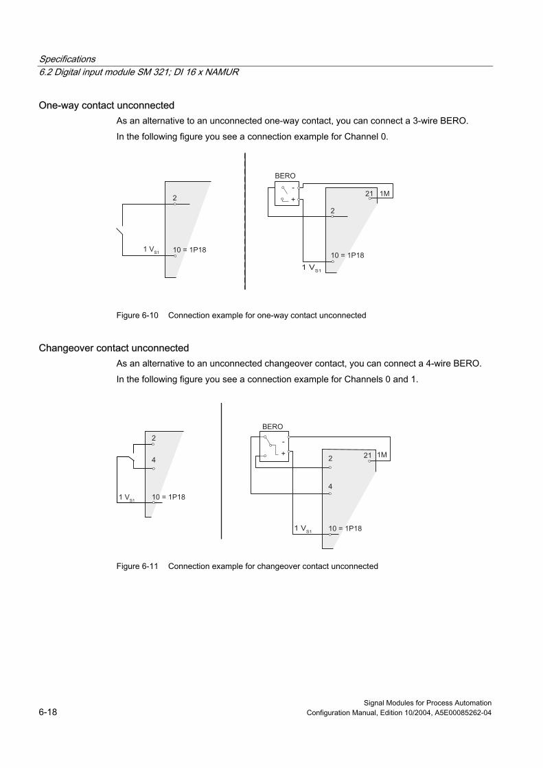
One-way contact unconnected As an alternative to an unconnected one-way contact, you can connect a 3-wire BERO.
In the following figure you see a connection example for Channel 0.
Figure 6-10 Connection example for one-way contact unconnected
Changeover contact unconnected As an alternative to an unconnected changeover contact, you can connect a 4-wire BERO.
In the following figure you see a connection example for Channels 0 and 1.
Figure 6-11 Connection example for changeover contact unconnected

Specifications 6.2 Digital input module SM 321; DI 16 x NAMUR
Signal Modules for Process Automation Configuration Manual, Edition 10/2004, A5E00085262-04 6-19
6.2.4 Diagnostics of the Digital Input Module
6.2.4.1 Diagnostics of the Digital Input Module In this section, you will find all the diagnostic messages of the digital input module that can occur in DP diagnostics and STEP 7 module diagnostics.
Diagnostic Messages, Causes and Remedies The module reports diagnostics for each channel. A visual indication is given by the SF- LED.
You can activate/deactivate and configure the diagnostics using the "Group Diagnostics" parameters.“.
Table 6-8 Diagnostic messages of the digital input module, causes and remedies
In DP diagnostics (channel-based)
Diagnostic message from module diagnostics
Possible cause Remedy
Sensor voltage supply failure Short-circuit (1D) P short-circuit (sensor) Short-circuit between the sensor line and the sensor voltage supply line
Eliminate overload/short-circuit
Interruption of the sensor line(s) or the sensor voltage supply line
Reestablish the connection
Break in the bridging resistance Eliminate interruption of the bridging resistance
Wire break (6D) Wire break
Defective sensor Replace the sensor Replace the defective sensor Flutter of sensor signal Reset the flutter monitoring
Fault (9D) Flutter error
Defective EEPROM Replace the module Load voltage L+ of module missing Connect load voltage L+ Sensor or load voltage
missing (17D) Sensor voltage supply failure Defective sensor voltage in module Replace the module
Defective sensor Replace the sensor Break in the bridging resistance Eliminate interruption of the
bridging resistance
External error (26D) Changeover contact diagnostics
Short-circuit in sensor voltage supply and sensor line at changeover signal change
Eliminate short-circuit
Description of the Diagnostic Evaluation You can find a detailed description of how to evaluate diagnostic information in the STEP 7 online help.

Specifications 6.2 Digital input module SM 321; DI 16 x NAMUR
Signal Modules for Process Automation 6-20 Configuration Manual, Edition 10/2004, A5E00085262-04
6.2.4.2 Diagnostics Based on the Sensor
Diagnostic Options The following table shows you which sensor suppy diagnostics.
Table 6-9 Diagnostics depending on sensor
Diagnostics to... NAMUR-compliant sensor
One-way contact
Changeover contact
3-Wire BERO
4-Wire BERO
Interruption of the sensor line or sensor voltage supply line
X If connected If connected If connected If connected
Break in the bridging resistance X If connected If connected If connected If connectedShort-circuit between sensor line(s) and sensor voltage supply line
X - Changeover error at signal change
- Changeover error at signal change
Load voltage L+ of module missing X X X X X Flutter of sensor signal X X X X X Defective sensor (normally open channel) = changeover contact error
With changeover contact
- X - X
See also Diagnostics Using the Process Image of Inputs (Page 5-1)
Diagnostic data (Page 5-2)

Specifications 6.2 Digital input module SM 321; DI 16 x NAMUR
Signal Modules for Process Automation Configuration Manual, Edition 10/2004, A5E00085262-04 6-21
6.2.4.3 Diagnosis with sensor changeover contact
Brief description In the case of diagnostics with a sensor of the changeover contact type, the module monitors switching between 2 input channels. If after the specified switchover time (see the technical specifications) there is no change in signal on the partner channel, the module generates diagnostics.
Purpose You can use the diagnostics as follows:
• For diagnostics of the sensor
• To check that there was definitely a switchover between the normally open contact and the normally closed contact
Operating Principle If the digital inputs of a channel group are configured as "changeover contacts", the module for this channel group carries out a diagnostics for the changeover contact type of sensor. The tolerated switchover time between the two channels is fixed at 300 ms and cannot be changed.
If the check is negative, then:
• The module identifies the value status of the normally open contact channel as "invalid".
• The module creates a diagnostic entry for the normally open contact channel.
• The module triggers a diagnostic interrupt.
The signal value of the channel for the normally open contact is updated. The value status of the normally open channel goes to BAD. If the partner channel changes within the switchover time, the test is aborted and the signal value at the normally open channel is updated. (The value status at the normally open channel is GOOD.)
The digital input signal for the normally closed contact channel is fixed "zero" regardless of the actual value in the process. The value status of the normally closed channel is always BAD.

Specifications 6.2 Digital input module SM 321; DI 16 x NAMUR
Signal Modules for Process Automation 6-22 Configuration Manual, Edition 10/2004, A5E00085262-04
Figure 6-12 Signal response for changeover contact diagnostics
Note the following points in the diagnostics for the changeover contact type of sensor:
• If there is already an error on the normally open contact channel (a wire break, for example), the module no longer performs diagnostics for changeover contact errors.
• The following table lists additional points:
Table 6-10 Diagnostics with changeover contact sensor
Changeover contact A negative result means... Changeover contact as NAMUR
• Short-circuit or • Wire break
Changeover contact connected
• Defective sensor or short-circuit It is not possible to distinguish between a defective sensor and a short-circuit.
Changeover contact unconnected
Caution: no difference possible between • signal "0" and wire break • signal "1" and short-circuit
In addition: Changeover contact or external error (in the case of DP diagnostics)

Specifications 6.3 Digital output module SM 322; DO 16 x DC 24 V/ 0.5 A
Signal Modules for Process Automation Configuration Manual, Edition 10/2004, A5E00085262-04 6-23
Diagnostics in the User Program You can find out how to evaluate the diagnostics in the user program in the STEP 7 online help system.
6.3 Digital output module SM 322; DO 16 x DC 24 V/ 0.5 A
6.3.1 Specifications
Order number 6ES7 322-8BH00-0AB0
6ES7 322-8BH01-0AB0
Properties The SM 322; DO 16xDC24V/0.5A has the following properties:
• 16 outputs, isolated in groups of 4
• A nominal load voltage of 24 V DC
• Configurable diagnostics
• Identification Data
• Wire break and short-circuit recognition at "0" signal (only with 6ES7 322-8BH01-0AB0)
Use with Rapid Counters When the 24 V supply voltage is connected via a mechanical contact, the outputs of the SM 322; DO 16xDC24V/0.5A carry the signal for approx. 50 μs "1"-depending on the circuit. You must take this into account if you use the SM 322; DO 16xDC24V/0.5A with rapid counters.

Specifications 6.3 Digital output module SM 322; DO 16 x DC 24 V/ 0.5 A
Signal Modules for Process Automation 6-24 Configuration Manual, Edition 10/2004, A5E00085262-04
Terminal Assignment and Block Diagram
Figure 6-13 Module view and block diagram of the SM 322; DO 16xDC24V/0.5A
Number Meaning 1 Status LED - green
Error LED - red 2 Channel number
Numbers 0 to 7 on the right side correspond to channel numbers 8 to 15 3 Channel status (green) 4 Channel error (red) 5 Backplane bus connection

Specifications 6.3 Digital output module SM 322; DO 16 x DC 24 V/ 0.5 A
Signal Modules for Process Automation Configuration Manual, Edition 10/2004, A5E00085262-04 6-25
Caution Reverse polarity of the load voltage In contrast to the response of the predecessor version, SM 322, with the order number 6ES7 322-8BH00-0AB0 the module fuse of the new SM 322 with the order number 6ES7 322-8BH01-0AB0 is destroyed if the polarity of the load voltage is reversed. The module then has to be sent in for repair.
When the polarity of the load voltage is reversed in the SM 322 with the order number 6ES7 322-8BH00-0AB0, the response of the output channels change: Unconnected channels output "1" instead of "0" and connected channels output "0" instead of "1"!
The module ignores the configured substitute values in each case.
Redundant Output Signals The output with a series diode can be used for redundant control of an actuator. Redundant control can take place from 2 different modules without an external circuit. The two signal modules must have the same reference potential (M).
Note Wire Break Detection If the output with series diode is used for the SM 322 with the order number 6ES7 322-8BH00-0AB0, external P short-circuits cannot be recognized as a wire break.
If the output with series diode is used for the SM 322 with the order number 6ES7 322-8BH01-0AB0, external P short-circuits are recognized as a wire break.
Specifications 6.3 Digital output module SM 322; DO 16 x DC 24 V/ 0.5 A
Signal Modules for Process Automation 6-26 Configuration Manual, Edition 10/2004, A5E00085262-04
Specifications
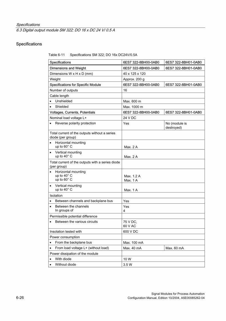
Table 6-11 Specifications SM 322; DO 16x DC24V/0.5A
Specifications 6ES7 322-8BH00-0AB0 6ES7 322-8BH01-0AB0 Dimensions and Weight 6ES7 322-8BH00-0AB0 6ES7 322-8BH01-0AB0 Dimensions W x H x D (mm) 40 x 125 x 120 Weight Approx. 200 g Specifications for Specific Module 6ES7 322-8BH00-0AB0 6ES7 322-8BH01-0AB0 Number of outputs 16 Cable length • Unshielded Max. 600 m • Shielded Max. 1000 m Voltages, Currents, Potentials 6ES7 322-8BH00-0AB0 6ES7 322-8BH01-0AB0 Nominal load voltage L+ 24 V DC • Reverse polarity protection Yes No (module is
destroyed) Total current of the outputs without a series diode (per group)
• Horizontal mounting up to 60° C
Max. 2 A
• Vertical mounting up to 40° C
Max. 2 A
Total current of the outputs with a series diode (per group)
• Horizontal mounting up to 40° C up to 60° C
Max. 1.2 A Max. 1 A
• Vertical mounting up to 40° C
Max. 1 A
Isolation • Between channels and backplane bus Yes • Between the channels
In groups of Yes 4
Permissible potential difference • Between the various circuits 75 V DC,
60 V AC Insolation tested with 600 V DC Power consumption • From the backplane bus Max. 100 mA • From load voltage L+ (without load) Max. 40 mA Max. 60 mA Power dissipation of the module • With diode 10 W • Without diode 3.5 W

Specifications 6.3 Digital output module SM 322; DO 16 x DC 24 V/ 0.5 A
Signal Modules for Process Automation Configuration Manual, Edition 10/2004, A5E00085262-04 6-27
Specifications 6ES7 322-8BH00-0AB0 6ES7 322-8BH01-0AB0 Status, Interrupts, Diagnostics 6ES7 322-8BH00-0AB0 6ES7 322-8BH01-0AB0 Status LEDs Green LED per channel Interrupts • Diagnostic interrupt Parameters can be assigned Diagnostic functions Parameters can be assigned • Group error display Red LED (SF) • Channel error display Red LED per channel (F) • Diagnostic information readable Possible Data for Selecting an Actuator 6ES7 322-8BH00-0AB0 6ES7 322-8BH01-0AB0 Output voltage • At signal "1" Min. L + (- 0.7 V) • At signal "0" – 0.5 mA * RL (RL = load
resistance value) max. 8.2 µm for RL = infinite
Output current • At signal "1"
Nominal value Permitted range
0.5 A 5 mA up to 600 mA
• At signal "0" (residual current)
Max. 0.5 mA
Output delay (with resistive load) • At "1" to "0" Max. 2.7 ms (including module cycle time) • At "1" to "0" Max. 2.7 ms (including module cycle time) Load resistor range 48 Ω bis 4kΩ Lamp load Max. 5 W Max. 5 W
Cold resistance > 48 Ω Lamp loads with a cold resistance of < 48 Ω have to be connected to the outputs with series diodes.
Connecting 2 outputs in parallel • For redundant triggering of a load Possible for outputs with series diodes • To increase performance Not possible Control of a digital input Possible Operating frequency • With resistive load Max. 100 Hz • With inductive load, to IEC 947-5-1, DC 13 Max. 2 Hz • With lamp load Max. 10 Hz Limit (internal) of the inductive circuit interruption voltage to
Typical L+ (-45 V)
Short-circuit of an output Yes, electronic • Response threshold Typical 0.7 A Typical 1.4 A

Specifications 6.3 Digital output module SM 322; DO 16 x DC 24 V/ 0.5 A
Signal Modules for Process Automation 6-28 Configuration Manual, Edition 10/2004, A5E00085262-04
6.3.2 Tips and notes about the SM 322 with order number 6ES7 322-8BH01-0AB0
Lamps Lamps which have a cold resistance lower than the minimum permissible resistance (48 Ω) have to be connected to the diode outputs.
This ensures that the diagnostic message M short circuit suppressed at "0" signal. The diagnosis P short circuit is no longer possible - wire break is signaled.
Load Impedances of the Actuators The load impedances of the actuators have to lie in the range of 48 Ω to 4 kΩ.
Otherwise, a suitable resistor must be switched in parallel directly to the terminals of the actuators (take the maximum power loss at Signal "1" into account).
The permissible nominal voltage of the actuator must exceed 28.2 V.
The lower response threshold of the actuator has to be known in the operating temperature range or has to be determined by experiment. The output voltage of the module at "0" signal can be influenced by connection in parallel of a resistor directly to the actuator terminals. When selecting the resistor, the maximum power loss at "1" signal has to be taken into consideration.
The maximum power loss is calculated from the following equation: Pmax_RL [W] = 795 [V2] / RL [Ω]
Note Design Information In order to achieve maximum protection in the module against EMC interference, it is advisable to design the ground wiring in star-type connection with an adequate cross-section.

Specifications 6.3 Digital output module SM 322; DO 16 x DC 24 V/ 0.5 A
Signal Modules for Process Automation Configuration Manual, Edition 10/2004, A5E00085262-04 6-29
6.3.3 Parameters of the digital output module
Parameters of the Digital Output Module The following table lists all the parameters of the digital output module.
Note Set the substitute value behavior in STEP 7 and the remaining parameters in PDM. When using STEP 7 as of V5.1 SP3 and PCS 7 as of V5.2 SP2, set all parameters with STEP 7 HW Config.
Table 6-12 Parameters of the digital output module
Parameters Value range Default setting Applicability Set in PDM: Diagnostics • Enabling: Diagnostic interrupt Yes/no No Module Diagnostics • Load voltage L+ missing Yes/no Yes Channel group • Group diagnostics Yes/no Yes Channel Set in STEP 7: Response at CPU-STOP Substitute a value/
Keep last value Substitute a value
Module
Substitute value 0/1 0 Channel

Specifications 6.3 Digital output module SM 322; DO 16 x DC 24 V/ 0.5 A
Signal Modules for Process Automation 6-30 Configuration Manual, Edition 10/2004, A5E00085262-04
Identification Data
Table 6-13 Identification data of the digital output module
Identification Data Value range Default setting Applicability Device Manufacturer reading SIEMENS AG Module Device identification reading 6ES7 322-8BH00-0AB0 or 6ES7
322-8BH01-0AB0 Module
Device serial number reading Module Hardware revision reading Module Software revision reading
Depends on the version
Module Static revision no. reading – Module Installation date Read/write (max. 16 characters) – Module Operating unit TAG Read/write (max. 32 characters) – Module Description Read/write (max. 32 characters) – Module
Note Access to identification data is only possible with SIMATIC PDM.
See also Identification Data (Page 6-10)

Specifications 6.3 Digital output module SM 322; DO 16 x DC 24 V/ 0.5 A
Signal Modules for Process Automation Configuration Manual, Edition 10/2004, A5E00085262-04 6-31
6.3.4 Diagnostics of the Digital Output Module
Diagnostics The module reports most diagnostics messages for each channel. Missing load voltage or the failure of fuse is reported for all 4 channels of the affected channel group.
Channel errors are signaled with the error indicator (Fx). As soon as at least one channel error indicator lights up, the common error indicator (SF) lights up.
You can activate/deactivate and the diagnostics using the "Group Diagnostics" parameter.
Diagnostic Messages, Causes and Remedies (6ES7 322-8BH00-0AB0)
Table 6-14 Diagnostic messages of the digital output module, causes and remedies
Diagnostic message in DP diagnostics (channel-based)
Diagnostic message from module diagnostics
Possible cause Remedy
M short-circuit Short-circuit of the output to M (channel group)
Short-circuit (1D)
P short-circuit Short-circuit of the output to L+ (channel group)
Eliminate short-circuit
Output overload Eliminate overload Excessive temperature (5D)
Excessive temperature Short-circuit of the output to M Eliminate short-circuit Interruption in the wire between the module and the actuator (only with "1" signal)
Reestablish the connection Wire break (6D) Wire break
Channel unused (open) Disable "wire break diagnostic" in the configuration of the channel
Fault (9D) Fuse failure Module defective Replace the module Sensor or load voltage missing (17D)
(Load) supply voltage missing
Load voltage L+ of module missing Connect load voltage L+

Specifications 6.3 Digital output module SM 322; DO 16 x DC 24 V/ 0.5 A
Signal Modules for Process Automation 6-32 Configuration Manual, Edition 10/2004, A5E00085262-04
Diagnostic Messages, Causes and Remedies (6ES7 322-8BH01-0AB0)
Table 6-15 Diagnostic messages of the digital output module, causes and remedies
Diagnostic messages in DP diagnostics (channel-based)
Diagnostic message from module diagnostics
Possible cause Remedy
Output without series diode Short-circuit (1D) M short-circuit (08H)
P short-circuit (04H) Short-circuit of the output to M Short-circuit of the output to L+
Eliminate short-circuit
Excessive temperature (5D)
Excessive temperature (80H)
Output overload Eliminate overload
Interruption in the wire between the module and the actuator
Reestablish the connection Wire break (6D) Wire break (10H)
Channel unused (open) in the configuration for the channel Disable "Group Diagnostics"
Error (9D) Fuse failure (20H) Module defective Replace the module Sensor or load voltage missing (17D)
(Load) supply voltage missing (40H)
Load voltage L+ or M ground of the channel group missing
Connect load voltage L+ or ground
Output with series diode Short-circuit (1D) M short-circuit (08H) Short-circuit of the output to M *) Eliminate short-circuit Excessive temperature (5D)
Excessive temperature (80H)
Output overload *) Eliminate overload
Interruption in the wire between the module and the actuator
Reestablish the connection
Channel unused (open) in the configuration for the channel Disable "Group Diagnostics"
Wire break (6D) Wire break (10H)
Short-circuit of the output to L+ Eliminate short-circuit Error (9D) Fuse failure (20H) Module defective Replace the module Sensor or load voltage missing (17D)
(Load) supply voltage missing (40H)
Load voltage L+ or M ground of the channel group missing
Connect load voltage L+ or ground
*) only for output signal "1"
Note The green channel status LED lights when there is 15 V or more at the output terminals of the module (from external power, for example).
M short-circuit and excessive temperature cannot be detected separately. Both errors are always displayed.

Specifications 6.3 Digital output module SM 322; DO 16 x DC 24 V/ 0.5 A
Signal Modules for Process Automation Configuration Manual, Edition 10/2004, A5E00085262-04 6-33
Response to M Short-circuit If output signal = "1", the digital output module reports "M short-circuit".
If output signal = "0", the digital output module switches to the safer status and the status LED turns off.
Note The digital output module reports a P short-circuit regardless of the signal status.
Description of the Diagnostic Evaluation You can find a detailed description of how to evaluate diagnostic information in the STEP 7 online help.

Specifications 6.3 Digital output module SM 322; DO 16 x DC 24 V/ 0.5 A
Signal Modules for Process Automation 6-34 Configuration Manual, Edition 10/2004, A5E00085262-04

Signal Modules for Process Automation Configuration Manual, Edition 10/2004, A5E00085262-04 A-1
Appendix AA.1 Dimension drawing
Dimension Drawing of the Signal Modules The figure below shows a dimension drawing of the signal modules.
The appearance of the signal modules can vary. However, the specified dimensions are always the same.
Figure A-1 Dimension drawing of the signal modules
Additional Dimension Drawings ... You can find dimension drawings of the modules and components of an S7-300 and ET 200M in the relevant manuals.

Appendix A.2 Service and Support
Signal Modules for Process Automation A-2 Configuration Manual, Edition 10/2004, A5E00085262-04
A.2 Service and Support
SIMATIC Technical Support You can find technical support for all A&D projects:
• via the Internet with Support Request: http://www.siemens.com/automation/support-request
• E-mail: [email protected]
• Telephone: +49 (0) 180 5050 222
• Fax: +49 (0) 180 5050 223
Further information about our technical support is available in the Internet at http://www.siemens.com/automation/service&support
Service & Support In the Internet In addition to our documentation, our extensive knowledge database is available on the Internet at:
http://www.siemens.com/automation/service&support where you will find the following:
• The latest product information, FAQs (Frequently Asked Questions), downloads, tips and tricks.
• The newsletter keeps you up-to-date with information relating to your products.
• The Knowledge Manager helps you find the documents you need.
• Users and specialists from around the world share their experience and knowledge in the Forum.
• You can find your local partner for Automation & Drives in our contacts database.
• Information about on-site services, repairs, spare parts and much more is available on our "Services" pages.
Further Support For answers you cannot find to questions on how to use the products described in the manual, please consult your SIEMENS representative. You can find your local SIEMENS representative at the following internet address:
You contact partner is found under:
http://www.siemens.com/automation/partner You can find the guide to the technical documentation for individual SIMATIC products and systems at:
http://www.siemens.de/simatic-tech-doku-portal

Appendix A.2 Service and Support
Signal Modules for Process Automation Configuration Manual, Edition 10/2004, A5E00085262-04 A-3
Training Center We offer relevant courses to simplify your introduction to the world of the S7-300 automation system. Please contact your regional training center, or the central training center in D-90327 Nuremberg.
Telephone:+49 (911) 895-3200
http://www.sitrain.com

Appendix A.2 Service and Support
Signal Modules for Process Automation A-4 Configuration Manual, Edition 10/2004, A5E00085262-04
Signal Modules for Process Automation Configuration Manual, Edition 10/2004, A5E00085262-04 Glossary-1
Glossary
BERO A position switch that works without any touch or contact being involved. A distinction is drawn between inductive and capacitive BEROs.
Flutter monitoring Flutter monitoring is a process control function for digital input signals. It detects and reports unusual process control signal patterns such as a fluctuation in the input signal between"0" and "1"that occurs too often. The occurrence of such signal patterns indicates that the sensor is faulty or unstable.
Identification Data Identification data is information stored in a module that supports the user with the following:
• Checking the configuration of a system
• Locating changes to the hardware of a system
NAMUR Normenausschuss für Mess- und Regelungstechnik (German standardization committee for measurement and control engineering)
Pulse stretching Pulse stretching is a function for changing a digital input signal. A pulse at a digital input is extended to at least the configured length. If the input pulse is already longer than the configured length, it is not changed.
Sensor Sensors are used for the precise detection of digital signals and paths, positions, speeds, revolutions, weights, etc.

Glossary
Signal Modules for Process Automation Glossary-2 Configuration Manual, Edition 10/2004, A5E00085262-04
Signal Modules for Process Automation Configuration Manual, Edition 10/2004, A5E00085262-04 Index-1
Index
6 6ES7 322-8BH00-0AB0, 6-23 6ES7 322-8BH01-0AB0, 6-23
B BERO, Glossary-1
Performance factor, 6-12 Requirements, 6-12
C Changeover contact
Diagnostics, 6-21 Changeover contact diagnostics, 6-19 COM PROFIBUS, 3-2 Configuration
Operating principle, 2-1 Configuring, 3-1 Connection
of sensors, 6-15
D DDB File
Integration in configuration software, 3-2 Device identification, 6-10 Device serial number, 6-10 Diagnostic messages
SM 321 DI 16xNAMUR, 6-19 Diagnostics
Data record 0 and 1, 5-2 Digital input module depending on sensor, 6-20 for changeover contact sensor, 6-21
Dimension drawing SM 321 DI 16xNAMUR, A-1 SM 322 DO 16xDC24V/0.5A, A-1
E Excessive temperature, 6-31
F Fault, 6-19, 6-31 Flutter error, 6-19 Flutter monitoring, 6-7, Glossary-1 Further support, A-2
G Group diagnostics, 6-19 GSD File
Downloading, 3-2
H Hardware requirements, 1-2 Hotline, A-2
I Identification data, 6-10, Glossary-1 Identification Data
SM 321 DI 16xNAMUR, 6-7 SM 322 DO 16xDC24V/0.5A, 6-30
Installation date, 6-10 Internet, A-2
M M short-circuit, 6-31, 6-33 Manufacturer, 6-10
N NAMUR, Glossary-1

Index
Signal Modules for Process Automation Index-2 Configuration Manual, Edition 10/2004, A5E00085262-04
P P short circuit, 6-31 Parameter
SM 321 DI 16xNAMUR, 6-6 Parameter Assignment, 4-1 Parameters
Flutter monitoring, 6-7, Glossary-1 Pulse stretching, 6-9, Glossary-1
Performance factor, 6-11 BERO, 6-13
Process control engineering, 1-4 Process control modules, 1-1
Integration in the process control system, 1-4 Product Overview, 1-1 Pulse stretching, 6-9, Glossary-1
R Revision
Hardware, 6-10 Software, 6-10
Revision number, 6-10
S Sensor, Glossary-1
Connecting, 6-15 Connection Guidelines, 6-11 Diagnostic options, 6-20 Sensor load factor, 6-13
Sensor as changeover contact Diagnostics, 6-21
Sensor load, 6-13 Sensor supply voltage, 6-11 Serial number, 6-10 Service, A-2 Short-circuit, 6-19, 6-31 Signal modules for process automation, 1-1 Signal Modules for Process Automation, 1-1 SIMATIC Customer Support Hotline, A-2 SM 321 DI 16xNAMUR, 6-2
Diagnostic messages, 6-19 Diagnostics depending on sensor, 6-20 Dimension drawing, A-1 Identification Data, 6-7 Parameter, 6-6 Specifications, 6-4 Terminal assignment and block diagram, 6-3
SM 322 DO 16xDC24V/0.5A, 6-23 Dimension drawing, A-1 Identification Data, 6-30 Specifications, 6-26 Terminal assignment and block diagram, 6-24
Software requirements, 1-2 Specifications
General, 6-1 SM 321 DI 16xNAMUR, 6-4 SM 322 DO 16xDC24V/0.5A, 6-26
STEP7, 1-3 Support, A-2
T TAG, 6-10 Terminal assignment and block diagram
SM 321 DI 16xNAMUR, 6-3 SM 322 DO 16xDC24V/0.5A, 6-24
Training Center, A-3
V Value status, 5-1
Evaluation in PCS 7, 5-2
W Wire break, 6-19, 6-31

Copyright 2004 by Siemens AGA5E00201782-03
Product Information on the Manual
Edition 12.2004
S7-300 Programmable Controller; Module Specifications, as of Edition 02/2004
(A5E00105505)
ET 200M Distributed I/O Device Signal Modules for Process Automation,
as of Edition 10/2004 (A5E00085262)
S7-300, ET 200M Programmable Controller, Modules with Intrinsically-Safe
Signals, as of Edition 08/2003 (A5E00172008)
Introduction
Parameterizable signal modules of the S7-300 product family mentioned in thisproduct information document can be reparameterized online using STEP7 HWCONFIG in RUN mode of the CPU.
In other words, the module parameters can be changed without switching the CPUto STOP mode or affecting other modules.
The following prerequisites must be met in order to use this function:
• STEP7 as of Version 5.2
• Distributed use of the S7-300 modules described in the S7-400 programmablecontroller (CPUs as of V3.1 or CP 443-5 extended as of V5.0).
• Use of the ET 200M with the IM 153-2 as of 6ES7153-2BA00-0XB0 or6ES7153-2BB00-0XB0
• Use of the IM 157 as of 6ES7157-0AA82-0XA00
You will find a detailed description of the prerequisites and principles of operation inthe manual Modifying the System during Operation via CiR (visit http://www.siemens.com/automation/service&support and enterthe entry ID: 14044916).

2Product Information on the Manual
A5E00201782-03
Reparameterization steps in RUN mode
Observe the reparameterization steps described in the above manual.
Note the peculiarities of certain modules described in the table.
Example 1:
To change a measuring range for modules, proceed as follows:
1. Change the user program so that the channel to be reparameterized is nolonger evaluated, and download it to the CPU.
2. Change the measuring range for the module in HWCONFIG, and download thechanged configuration to the CPU.
3. Adapt the user program to the changed channel, and download it to the CPU.
Example 2:
When reparameterizing certain modules (see the table), you should ensure thatthere is no pending diagnostic event (e.g. a wire break message) before carryingout reparameterization, since otherwise it may happen in some cases that outgoingdiagnostic events are no longer reported. As a result, the SF LEDs on the CPU,IM, or module will continue to shine, for example, although the reparameterizedmodule is working correctly. If such a situation does arise, however, the modulemust be removed and then plugged in again.
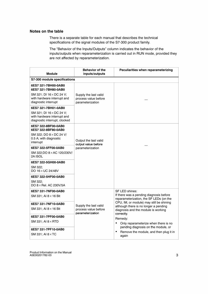
3Product Information on the ManualA5E00201782-03
Notes on the table
There is a separate table for each manual that describes the technicalspecifications of the signal modules of the S7-300 product family.
The “Behavior of the Inputs/Outputs” column indicates the behavior of theinputs/outputs when reparameterization is carried out in RUN mode, provided theyare not affected by reparameterization.
ModuleBehavior of theinputs/outputs
Peculiarities when reparameterizing
S7-300 module specifications
6ES7 321-7BH00-0AB06ES7 321-7BH80-0AB0
SM 321; DI 16DC 24 V;with hardware interrupt anddiagnostic interrupt
Supply the last validprocess value beforeparameterization
---
6ES7 321-7BH01-0AB0
SM 321; DI 16DC 24 V;with hardware interrupt anddiagnostic interrupt, clocked
6ES7 322-8BF00-0AB06ES7 322-8BF80-0AB0
SM 322; DO 8DC 24 V/0.5 A; with diagnosticinterrupt Output the last valid
output value before6ES7 322-5FF00-0AB0
SM 322;DO 8AC 120/230V/2A ISOL
output value beforeparameterization
---
6ES7 322-5GH00-0AB0
SM 322; DO 16UC 24/48V
6ES7 322-5HF00-0AB0
SM 322; DO 8Rel. AC 230V/5A
6ES7 331-7NF00-0AB0
SM 331; AI 816 Bit
SF LED shines:If there was a pending diagnosis beforereparameterization, the SF LEDs (on theC )6ES7 331-7NF10-0AB0
SM 331; AI 816 BitSupply the last validprocess value beforeparameterization
p , (CPU, IM, or module) may still be shiningalthough there is no longer a pendingdiagnosis and the module is workingcorrectly
6ES7 331-7PF00-0AB0
SM 331; AI 8RTD
parameterization correctly.
Remedy:
• Only reparameterize when there is nopending diagnosis on the module or
6ES7 331-7PF10-0AB0
SM 331; AI 8TC
pending diagnosis on the module, or
• Remove the module, and then plug it inagain

4Product Information on the Manual
A5E00201782-03
ModulePeculiarities when reparameterizingBehavior of the
inputs/outputs
6ES7 332-5HD01-0AB0
SM 332; AO 412 Bit
Output the last validoutput value before
t i ti
SF LED shines:
If there was a pending diagnosis beforereparameterization, the SF LEDs (on theCPU, IM, or module) may still be shiningalthough there is no longer a pendingdiagnosis and the module is working
6ES7 332-5HB01-0AB06ES7 332-5HB81-0AB0
SM 332; AO 212 Bit
parameterizationdiagnosis and the module is workingcorrectly.
Remedy:
• Only reparameterize when there is nopending diagnosis on the module, or
• Remove the module, and then plug it inagain
6ES7 332-5HF00-0AB0SM 332; AO 812 Bit
---
6ES7 332-7ND00-0AB06ES7 332-7ND01-0AB0
SM 332; AO 416 Bit---
ModuleBehavior of theinputs/outputs
Peculiarities when reparameterizing
ET 200M signal modules for process automation (PCS7)
6ES7 321-7TH00-0AB0
SM 321; DI 16NAMUR
Supply the last validprocess value (includingthe value status) beforeparameterization
SF LED shines:
If there was a pending diagnosis beforereparameterization, the SF LEDs (on theCPU, IM, or module) may still be shiningalthough there is no longer a pendingdiagnosis and the module is workingcorrectly.
Remedy:6ES7 322-8BH00-0AB0
SM 322; DO 16DC 24V/0,5A
Output the last validoutput value beforeparameterization
Remedy:
• Only reparameterize when there is nopending diagnosis on the module, or
• Remove the module, and then plug it inagain

5Product Information on the ManualA5E00201782-03
ModulePeculiarities when reparameterizingBehavior of the
inputs/outputs
S7-300, ET 200, I/O modules with intrinsically-safe signals
6ES7 321-7RD00-0AB0
SM 321; DI 4NAMUR
Supply the last validprocess value beforeparameterization
SF LED shines:
If there was a pending diagnosis beforereparameterization, the SF LEDs (on theCPU, IM, or module) may still be shiningalthough there is no longer a pendingdiagnosis and the module is workingcorrectly.
Remedy:
• Only reparameterize when there is nopending diagnosis on the module, or
• Remove the module, and then plug it inagain
6ES7 322 5RD00-0AB0
SM 322; DO 415V/20mA
Output the last validoutput value beforeparameterization
6ES7 322-5SD00-0AB0
SM 322; DO 424V/10mA
parameterization---
6ES7 331-7RD00-0AB0
SM 331; AI 40/4...20mA ---
6ES7 331-7SF00-0AB0
SM 331; AI 8TC/4RTD
Supply the last validprocess value beforeparameterization
---
6ES7 331-7TB00-0AB0
SM 331; AI 20/4...20mAHART
parameterization
---
6ES7 332-5RD00-0AB0
SM 332; AO 40/4...20mA
Output the last validoutput value beforeparameterization
SF LED shines:
If there was a pending diagnosis beforereparameterization, the SF LEDs (on theCPU, IM, or module) may still be shiningalthough there is no longer a pendingdiagnosis and the module is workingcorrectly.
Remedy:
• Only reparameterize when there is nopending diagnosis on the module, or
• Remove the module, and then plug it inagain
6ES7 332-5TB00-0AB0
SM 332; AO 20/4...20mAHART
---

6Product Information on the Manual
A5E00201782-03