estimation of speed and parameter identification in ... · pdf fileseveral speed estimation...
TRANSCRIPT

International Research Journal of Engineering and Technology (IRJET) e-ISSN: 2395 -0056
Volume: 02 Issue: 04 | July-2015 www.irjet.net p-ISSN: 2395-0072
© 2015, IRJET ISO 9001:2008 Certified Journal Page 1982
Estimation of speed and Parameter identification in Sensorless IM
drive By using Second order Sliding-mode Observer and
MRAS techniques
M. Anka Rao
1, Dr. M. Vijaya Kumar2, B. Mukteswari3 1 Assistant professor, Department of EEE, JNTU Anantapur, Andhra Pradesh, India
2professor, Department of EEE, JNTU Anantapur, Andhra Pradesh, India 3 Student, Department of EEE, JNTU Anantapur, Andhra Pradesh, India
---------------------------------------------------------------------***---------------------------------------------------------------------Abstract-This paper presents a comparitive study of
performance of sensor and sensorless IFO IM drives. In
case of operation of drives with sensors, has good
dynamic performance at high and medium speed
operation. Where as at low speed operation, the
performance of the drive is not satisfactory. To get
satisfactory performance even at low speeds
sensorless controlled IM drives with MRAS and Sliding
mode observer is designed. Sensorless control has good
dynamic response compared to drives with sensor. In a
sensorless induction motor drive, A Stator current
observer is designed based on the second-order sliding
mode which is used as the reference model of the MRAS
estimator. The phase angle error between the actual
and estimated rotor flux vectors is used to tune the
adaptive model of MRAS estimator. The sliding mode
observer is insensitive to variation of stator resistance,
rotor resistance and perturbation when the states
arrive the sliding mode. By making full use of auxiliary
sliding-mode surfaces, the proposed observer
successfully reduces the chattering behavior.
Furthermore, in order to improve the near zero speed
operation, a parallel adaptive identification of stator
resistance is designed based on derivatives of rotor
flux and stator current.
Key Words: Induction motors (IMs), model reference
adaptive system (MRAS) estimator, supertwisting
algorithm Sensorless control, second order sliding mode,
parameter estimation, Low speed operation.
1.INTRODUCTION
Now-a-days induction motors (IM) have replaced DC
motors in the industrial applications. High performance
sensorless induction motor drives have attracted a great
attention in industrial applications due to their
advantages such as low cost, less maintenance, and high
reliability etc. The sensorless control helps to reduce the
cost and resolves installing problems in many
applications. There are many different ways to drive an
induction motor. The Differences between them are the
performance of motor and the cost of implementation.
At present efforts are devoted to improve the
performance of observer at low speeds, and to develop a
robust observer against perturbations and variation of
parameters.
Several methods have been proposed to estimate speed
and flux of IM such as: Luenberger observer and kalman
filter, high gain and adaptive observers, neural networks
and signal injection, and sliding mode observer etc.
Compared with the other methods, sliding mode
techniques has attractive advantage of robustness to
disturbances and insensitive to parameter variation
when the sliding mode is reached. However, the
chattering behavior, that is inherent in standard sliding
mode techniques, is often an obstacle for practical
applications if neglected. Higher order sliding mode is
one of the solutions which does not compromise
robustness and avoids filtering estimation considered by
other methods.
An improved rotor flux based model reference adaptive
system (MRAS) scheme with a parallel rotor speed and
stator resistance estimation algorithm is considered.
Both the differences in instantaneous phase and
amplitudes are used for speed estimation and stator
resistance identification. In addition, the mismatch
of rotor resistance introduces errors to the
estimated speed in wide speed range operation.
Compared with , rotor resistance is more difficult to
be identified online since the parallel estimation of
speed and rotor resistance is possible only if rotor flux
International Research Journal of Engineering and Technology (IRJET) e-ISSN: 2395 -0056
Volume: 02 Issue: 01 | Jan-2015 www.irjet.net p-ISSN: 2395-0072
© 2015, IRJET.NET- All Rights Reserved Page 1983
varies, which is not the case in steady state. Since the
rotor inductance can be treated as a constant, the
rotor time constant identification is equivalent to the
identification. So far numerous online parameter
estimation techniques have been proposed on the basis
of existing speed estimation schemes, which are able to
improve dynamic characteristics and noise immunity, as
well as insensitivity to parameter variations. In this
scheme, both rotor speed and rotor time constant can be
estimated by a sliding function based on a second-order
system.
Extended kalman filters (EKF) based estimation scheme
has significantly increased the accuracy of the estimation
of the estimation of the stator and rotor resistances
However, they have no specific tuning criteria. Sliding
mode observers are recognized for their robustness
against parameter variations, yet they suffer from
chattering behavior at the same. By using auxiliary
sliding mode surface chattering behavior can be
reduced.
2. SVM BASED INDIRECT VECTOR
CONTROLLED IM DRIVE
Several speed estimation techniques are available, for
IM drives. In this case performance of indirect field
oriented controlled IM drive specially at low speeds is
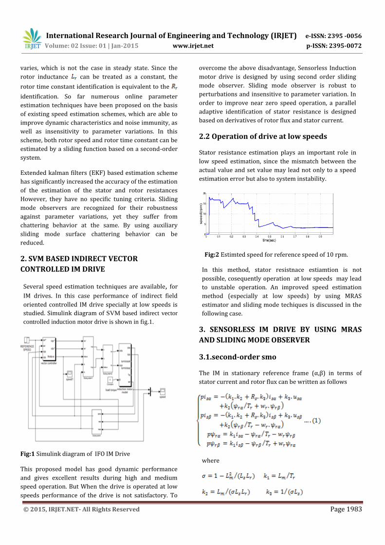
studied. Simulink diagram of SVM based indirect vector
controlled induction motor drive is shown in fig.1.
Fig:1 Simulink diagram of IFO IM Drive
This proposed model has good dynamic performance
and gives excellent results during high and medium
speed operation. But When the drive is operated at low
speeds performance of the drive is not satisfactory. To
overcome the above disadvantage, Sensorless Induction
motor drive is designed by using second order sliding
mode observer. Sliding mode observer is robust to
perturbations and insensitive to parameter variation. In
order to improve near zero speed operation, a parallel
adaptive identification of stator resistance is designed
based on derivatives of rotor flux and stator current.
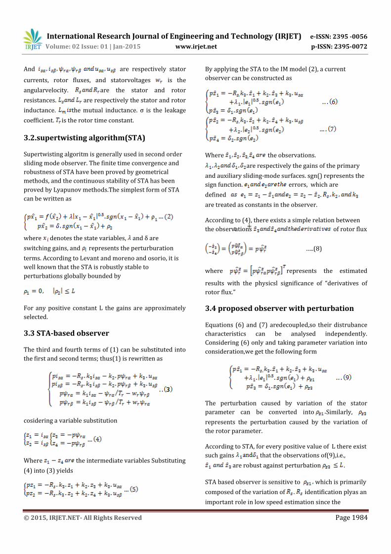
2.2 Operation of drive at low speeds
Stator resistance estimation plays an important role in
low speed estimation, since the mismatch between the
actual value and set value may lead not only to a speed
estimation error but also to system instability.
Fig:2 Estimted speed for reference speed of 10 rpm.
In this method, stator resistnace estiamtion is not
possible, cosequently operation at low speeds may lead
to unstable operation. An improved speed estimation
method (especially at low speeds) by using MRAS
estimator and sliding mode techiques is discussed in the
following case.
3. SENSORLESS IM DRIVE BY USING MRAS
AND SLIDING MODE OBSERVER
3.1.second-order smo
The IM in stationary reference frame (α,β) in terms of
stator current and rotor flux can be written as follows
where
International Research Journal of Engineering and Technology (IRJET) e-ISSN: 2395 -0056
Volume: 02 Issue: 01 | Jan-2015 www.irjet.net p-ISSN: 2395-0072
© 2015, IRJET.NET- All Rights Reserved Page 1984
And are respectively stator
currents, rotor fluxes, and statorvoltages is the
angularvelocity. are the stator and rotor
resistances. are respectively the stator and rotor
inductance. the mutual inductance. σ is the leakage
coefficient. is the rotor time constant.
3.2.supertwisting algorithm(STA)
Supertwisting algoritm is generally used in second order
sliding mode observer. The finite time convergence and
robustness of STA have been proved by geometrical
methods, and the continuous stability of STA has been
proved by Lyapunov methods.The simplest form of STA
can be written as
where denotes the state variables, and δ are
switching gains, and represents the perturburation
terms. According to Levant and moreno and osorio, it is
well known that the STA is robustly stable to
perturbations globally bounded by
For any positive constant L the gains are approximately
selected.
3.3 STA-based observer
The third and fourth terms of (1) can be substituted into
the first and second terms; thus(1) is rewritten as
cosidering a variable substitution
Where the intermediate variables Substituting
(4) into (3) yields
By applying the STA to the IM model (2), a current
observer can be constructed as
Where the observations.
are respectively the gains of the primary
and auxiliary sliding-mode surfaces. sgn() represents the
sign function. errors, which are
defined .
are treated as constants in the observer.
According to (4), there exists a simple relation between
the observations of rotor flux
…..(8)
where represents the estimated
results with the physicsl significance of “derivatives of
rotor flux.”
3.4 proposed observer with perturbation
Equations (6) and (7) aredecoupled,so their distrubance
characteristics can be analysed independently.
Considering (6) only and taking parameter variation into
consideration,we get the following form
The perturbation caused by variation of the stator
parameter can be converted into Similarly,
represents the perturbation caused by the variation of
the rotor parameter.
According to STA, for every positive value of L there exist
such gains that the observations of(9),i.e.,
are robust against perturbation .
STA based observer is sensitive to which is primarily
composed of the variation of . identification plyas an
important role in low speed estimation since the

International Research Journal of Engineering and Technology (IRJET) e-ISSN: 2395 -0056
Volume: 02 Issue: 01 | Jan-2015 www.irjet.net p-ISSN: 2395-0072
© 2015, IRJET.NET- All Rights Reserved Page 1985
mismatch between the actual value and set value may
lead not only to a speed estimation error but also to
system instability. On the other hand can still be
treated as constant in (6) and (7) because it varies slowly
compared to electrical signal.
In discrete time, the kth observation error is calculated
by e(k)=z(k)- where z(k) is real component, is
estimated one. Thus, e(k-1) is the (k-1)th observation
error, which is used to calculate the estimated .
Fig-3:Flowchart of discrete-time STA based observer
If the gains are selected according to the conditions that
they presented, the error states are ultimately bounded.
In other words, the trajectories of system enter into a
boundary layer in the victinity of the sliding mode and
stay inside it forever. This algorithm is termed as
supertwisting-like algorithm. For The continuous second-
order SMO shown in (6) and (7) the discrete observer is
obtained. The gains of the discrete STA based observer
should satisfy the necessary and sufficient conditions for
the existence of the sliding-mode hyperplane in discrete
time. The conditons were obtained by using Lyapunov
function.
The necessary and suficient conditions to ensure the
sliding motion on the hyperplane are obtained
[e(k+1)-e(k)].sgn(e(k))<0
4 SPEED ESTIMATION SHEME
4.1.Standard MRAS speed estimator
MRAS speed estimation makes use of two machine
models with different structures that estimate the same
motor state. The motor states may be rotor flux, back emf
or reactive power etc. Choosing the rotor flux to be the
state, the estimation error can be
The phase angle error between actual and estimated
rotor flux vectors is used to tune the speed as is
illustrated in fig.4.
Fig-4:Block diagram of standard rotor based MRAS
estimator.
4.2.Proposed MRAS speed estimator
In proposed estimator derivatives of rotor flux is used as
state, an adaptive mechanism of speed based on these
observations is required. For speed estimation, the
output of reference model is regarded as equal to the
actual rotor flux vector , and Hence
Eventually the estimation equation of rotorspeed is
where
(14)
Compared with the standard MRAS speed estimation,
the proposed speed estimator eliminates the integrators,
thus simplifying the system and avoiding the problems
caused by integration.
4.3 Parallel identification
Stator resistance ( ) plays an important role in low-
speed estimation since the mismatch between the actual
value and set value may lead not only to a speed
estimation error but also to system instability. The offline
estimation of is not sufficient because the actual value
varies due to complex reasons, such as temperature.
Parallel estimation is based on derivatives of rotor
International Research Journal of Engineering and Technology (IRJET) e-ISSN: 2395 -0056
Volume: 02 Issue: 01 | Jan-2015 www.irjet.net p-ISSN: 2395-0072
© 2015, IRJET.NET- All Rights Reserved Page 1986
flux. In case of parallel estimation reference model and
adjustable model exchange their roles.
Symbols and respectively stand for actual and
estimated rotor flux vectors of voltage model
The voltage model of IM can be written as
The observer equation is
When the estimation error trajectory reaches the sliding
mode, we get Eventually the estimation of stator
resistance obtaned as
where
is treated as constant in the STA-based observer
because it changes much slower than electric signals such
as stator voltage and current.
4.4.SSM scheme
The proposed SSM sheme used in this paper is a
combination of STA-based SMO and MRAS estimator
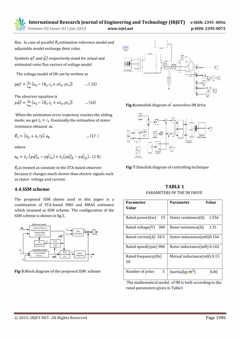
which isnamed as SSM scheme. The configuration of the
SSM scheme is shown in fig.5.
Fig-5:Block diagram of the proposed SSM scheme
Fig-6:simulink diagram of sensorless IM drive
Fig-7:Simulink diagram of controlling technique
TABLE 1 PARAMETERS OF THE IM DRIVE
Parameter
Value
Parameter Value
Rated power(kw) 15 Stator resistance(Ω) 1.556
Rated voltage(V) 380 Rotor resistance(Ω) 1.31
Rated current(A) 18.5 Stator inductance(mH)0.156
Rated speed(rpm) 980 Rotor inductance(mH) 0.162
Rated frequency(Hz)
50
Mutual inductance(mH) 0.15
Number of poles 3 Inertia(kg- ) 0.06
The mathematical model of IM is built according to the
rated parameters given in Table1
International Research Journal of Engineering and Technology (IRJET) e-ISSN: 2395 -0056
Volume: 02 Issue: 01 | Jan-2015 www.irjet.net p-ISSN: 2395-0072
© 2015, IRJET.NET- All Rights Reserved Page 1987
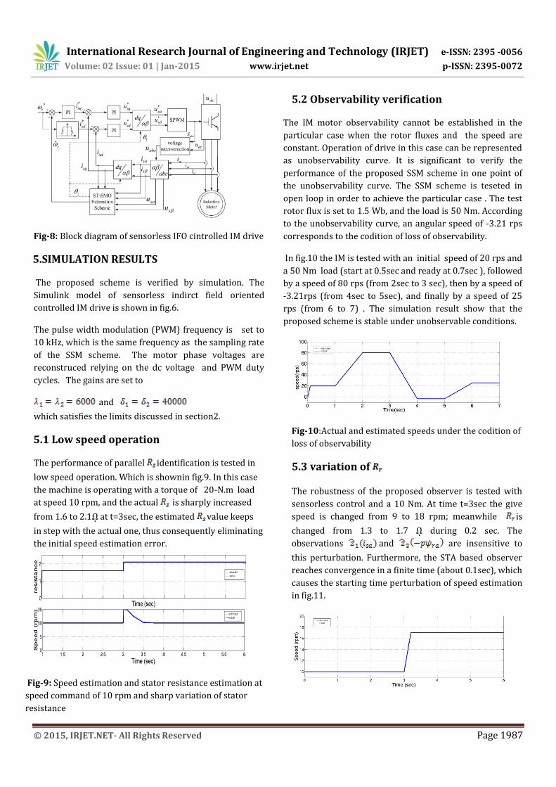
Fig-8: Block diagram of sensorless IFO cintrolled IM drive
5.SIMULATION RESULTS
The proposed scheme is verified by simulation. The
Simulink model of sensorless indirct field oriented
controlled IM drive is shown in fig.6.
The pulse width modulation (PWM) frequency is set to
10 kHz, which is the same frequency as the sampling rate
of the SSM scheme. The motor phase voltages are
reconstruced relying on the dc voltage and PWM duty
cycles. The gains are set to
and
which satisfies the limits discussed in section2.
5.1 Low speed operation
The performance of parallel identification is tested in
low speed operation. Which is shownin fig.9. In this case
the machine is operating with a torque of 20-N.m load
at speed 10 rpm, and the actual is sharply increased
from 1.6 to 2.1ῼ at t=3sec, the estimated value keeps
in step with the actual one, thus consequently eliminating
the initial speed estimation error.
Fig-9: Speed estimation and stator resistance estimation at
speed command of 10 rpm and sharp variation of stator
resistance
5.2 Observability verification
The IM motor observability cannot be established in the
particular case when the rotor fluxes and the speed are
constant. Operation of drive in this case can be represented
as unobservability curve. It is significant to verify the
performance of the proposed SSM scheme in one point of
the unobservability curve. The SSM scheme is teseted in
open loop in order to achieve the particular case . The test
rotor flux is set to 1.5 Wb, and the load is 50 Nm. According
to the unobservability curve, an angular speed of -3.21 rps
corresponds to the codition of loss of observability.
In fig.10 the IM is tested with an initial speed of 20 rps and
a 50 Nm load (start at 0.5sec and ready at 0.7sec ), followed
by a speed of 80 rps (from 2sec to 3 sec), then by a speed of
-3.21rps (from 4sec to 5sec), and finally by a speed of 25
rps (from 6 to 7) . The simulation result show that the
proposed scheme is stable under unobservable conditions.
Fig-10:Actual and estimated speeds under the codition of
loss of observability
5.3 variation of
The robustness of the proposed observer is tested with
sensorless control and a 10 Nm. At time t=3sec the give
speed is changed from 9 to 18 rpm; meanwhile is
changed from 1.3 to 1.7 ῼ during 0.2 sec. The
observations and are insensitive to
this perturbation. Furthermore, the STA based observer
reaches convergence in a finite time (about 0.1sec), which
causes the starting time perturbation of speed estimation
in fig.11.
International Research Journal of Engineering and Technology (IRJET) e-ISSN: 2395 -0056
Volume: 02 Issue: 01 | Jan-2015 www.irjet.net p-ISSN: 2395-0072
© 2015, IRJET.NET- All Rights Reserved Page 1988
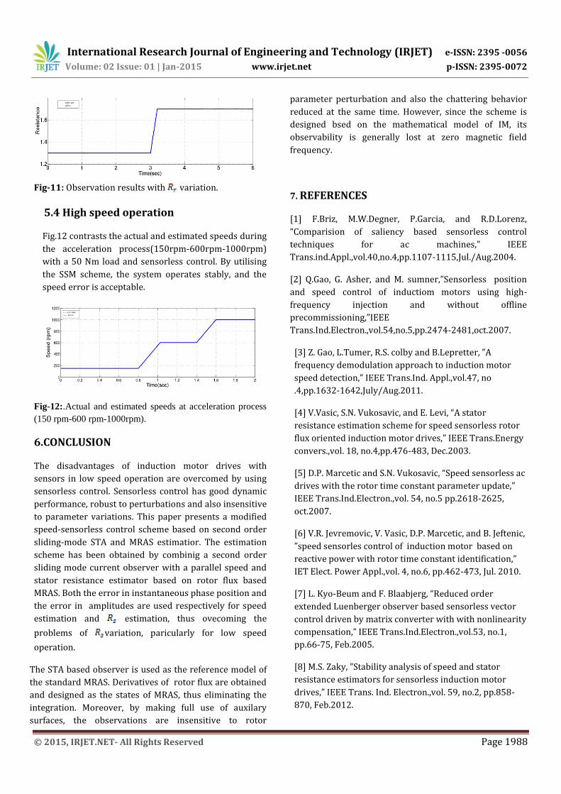
Fig-11: Observation results with variation.
5.4 High speed operation
Fig.12 contrasts the actual and estimated speeds during
the acceleration process(150rpm-600rpm-1000rpm)
with a 50 Nm load and sensorless control. By utilising
the SSM scheme, the system operates stably, and the
speed error is acceptable.
Fig-12:.Actual and estimated speeds at acceleration process
(150 rpm-600 rpm-1000rpm).
6.CONCLUSION
The disadvantages of induction motor drives with
sensors in low speed operation are overcomed by using
sensorless control. Sensorless control has good dynamic
performance, robust to perturbations and also insensitive
to parameter variations. This paper presents a modified
speed-sensorless control scheme based on second order
sliding-mode STA and MRAS estimatior. The estimation
scheme has been obtained by combinig a second order
sliding mode current observer with a parallel speed and
stator resistance estimator based on rotor flux based
MRAS. Both the error in instantaneous phase position and
the error in amplitudes are used respectively for speed
estimation and estimation, thus ovecoming the
problems of variation, paricularly for low speed
operation.
The STA based observer is used as the reference model of
the standard MRAS. Derivatives of rotor flux are obtained
and designed as the states of MRAS, thus eliminating the
integration. Moreover, by making full use of auxilary
surfaces, the observations are insensitive to rotor
parameter perturbation and also the chattering behavior
reduced at the same time. However, since the scheme is
designed bsed on the mathematical model of IM, its
observability is generally lost at zero magnetic field
frequency.
7. REFERENCES
[1] F.Briz, M.W.Degner, P.Garcia, and R.D.Lorenz,
“Comparision of saliency based sensorless control
techniques for ac machines,” IEEE
Trans.ind.Appl.,vol.40,no.4,pp.1107-1115,Jul./Aug.2004.
[2] Q.Gao, G. Asher, and M. sumner,”Sensorless position
and speed control of inductiom motors using high-
frequency injection and without offline
precommissioning,”IEEE
Trans.Ind.Electron.,vol.54,no.5,pp.2474-2481,oct.2007.
[3] Z. Gao, L.Tumer, R.S. colby and B.Lepretter, ”A
frequency demodulation approach to induction motor
speed detection,” IEEE Trans.Ind. Appl.,vol.47, no
.4,pp.1632-1642,July/Aug.2011.
[4] V.Vasic, S.N. Vukosavic, and E. Levi, “A stator
resistance estimation scheme for speed sensorless rotor
flux oriented induction motor drives,” IEEE Trans.Energy
convers.,vol. 18, no.4,pp.476-483, Dec.2003.
[5] D.P. Marcetic and S.N. Vukosavic, “Speed sensorless ac
drives with the rotor time constant parameter update,”
IEEE Trans.Ind.Electron.,vol. 54, no.5 pp.2618-2625,
oct.2007.
[6] V.R. Jevremovic, V. Vasic, D.P. Marcetic, and B. Jeftenic,
”speed sensorles control of induction motor based on
reactive power with rotor time constant identification,”
IET Elect. Power Appl.,vol. 4, no.6, pp.462-473, Jul. 2010.
[7] L. Kyo-Beum and F. Blaabjerg, “Reduced order
extended Luenberger observer based sensorless vector
control driven by matrix converter with with nonlinearity
compensation,” IEEE Trans.Ind.Electron.,vol.53, no.1,
pp.66-75, Feb.2005.
[8] M.S. Zaky, ”Stability analysis of speed and stator
resistance estimators for sensorless induction motor
drives,” IEEE Trans. Ind. Electron.,vol. 59, no.2, pp.858-
870, Feb.2012.

International Research Journal of Engineering and Technology (IRJET) e-ISSN: 2395 -0056
Volume: 02 Issue: 01 | Jan-2015 www.irjet.net p-ISSN: 2395-0072
© 2015, IRJET.NET- All Rights Reserved Page 1989
[9] M. Barut, S. Bogosyan, and M. Gokasan, “Experimental
evaluation of braided EKF for sensorless control of
induction motors,” IEEE Trans.Ind. Electorn.,vol.55, no.2,
pp. 620-632, Feb.2008.
[10] M.S Zaky, M.M. Khater S.S. Shokralla, and H.A. Yasin,
”Wide speed range estimation with online parameter
identification scheme of sensorless induction motor
drives,” IEEE Trans. Ind. Appl.,vol. 42, no.3, pp. 694-701,
May/Jun.2006.
[11] Z. Zhang, H.S Xu L.Y. Xu and L.E .Helian, “sensorless
direct field oriented control of three phase induction
motors based on “sliding mode” for washing machine
drive applications, “ IEEE Trans. Ind. Appl.,vol. 42, no.3,
pp. 694-701, May /Jun.2006.
[12] S. Solvar, V. Le, M. Ghanes, J-P. Barbot and G.
Santomenna, “sensorless second order sliding mode
observer for induction motor, ” in Proc. IEEE CCA,
Yokohama, Japan, 2010, pp. 1933-1938.
BIOGRAPHIES
M. Anka Rao is a Assistant
Professor in EEE Department
at JNTUA Anantapur. His
areas of interest are Power
Electronics, Electrical Drives.
Dr.M. Vijaya Kumar is a Professor in EEE Department and also served as a Director of Admissions at JNTUA Anantapur, Andhra Pradesh. His areas of interest are ElectricalMachines, Electrical Drives, Microprocessors and power Electronics.
B. Mukteswari currently pursuing M. Tech in Power and industrial drives at JNTUA Anantapur, Andhra Pradesh. Her areas of interest are Electrical Drives, Power Electronics.