estimation of soil permittivity in presence of antenna-soil interactions
TRANSCRIPT

IEEE JOURNAL OF SELECTED TOPICS IN APPLIED EARTH OBSERVATIONS AND REMOTE SENSING, VOL. 7, NO. 3, MARCH 2014 805
Estimation of Soil Permittivity in Presence ofAntenna-Soil Interactions
Raffaele Solimene, Antonietta D’Alterio, Gianluca Gennarelli, and Francesco Soldovieri, Senior Member, IEEE
Abstract—This work deals with a technique for estimating thesoil permittivity starting from Ground-Penetrating-Radar (GPR)measurements collected under a reflection mode single view (onetransmitting antenna) multistatic (plurality of receivers) configu-ration. The technique consists of two steps: i) first the soil Fresnelreflection coefficient is estimated; ii) then the soil electromagneticparameters are inferred from the retrieved reflection coefficient.In real scenarios, the transmitting antenna couples with thesoil as it is in close proximity of the air-soil interface so thatmutual interactions arise. Accordingly, the transmitting antennaplane-wave spectrum depends on the electromagnetic propertiesof the medium under investigation. This strongly complicates theproblem as the first step becomes a non-linear inverse problem.To overcome such a drawback, a pre-processing stage consistingof a suitable time gating procedure is here introduced. This allowsto restore linearity of the Fresnel coefficient estimation. Moreover,it is also able to mitigate negative effect due to not matchedtransmitting antenna. Numerical examples are presented to assessthe feasibility of the proposed technique.
Index Terms—Antenna/soil coupling, ground penetrating radar,inverse problem, soil permittivity estimation.
I. INTRODUCTION
S UBSURFACE imaging via Ground Penetrating Radar(GPR) is a well-assessed research field which finds appli-
cation in several contexts [1].Many focusing/inversion algorithms have been developed
with the aim of improving the imaging performance comparedto the simple radargrams [2]. Despite subsurface imagingentails dealing with the presence of the soil which, in general,is not homogeneous and has a rough air/soil interface, suchimaging algorithms have proven to work in realistic conditionsalso under the assumption of a homogeneous half-space soil anda planar air/soil interface. However, even in such a simplifiedscenario, the electromagnetic properties of soil are generallynot a priori known and, if not accurately accounted for in theinversion algorithm, blurred and delocalized reconstructionsarise [3]. Accordingly, regardless of the algorithm one decidesto adopt, an accurate knowledge of soil electromagnetic param-eters is mandatory to obtain well-focused subsurface images.
Manuscript received December 15, 2012; accepted May 29, 2013. Date ofpublication July 02, 2013; date of current version March 14, 2014.R. Solimene and A. D’Alterio are with the Dipartimento di Ingegneria Indus-
triale e dell’Informazione, Seconda Università di Napoli, 81031 Aversa, Italy.G. Gennarelli and F. Soldovieri are with the Institute for the Electromagnetic
Sensing of the Environment, Italian National Research Council, 80125 Napoli,Italy (corresponding author e-mail: [email protected]).Color versions of one or more of the figures in this paper are available online
at http://ieeexplore.ieee.org.Digital Object Identifier 10.1109/JSTARS.2013.2268576
Note that this necessity arises also in several hydrological ap-plications, such as optimal irrigation and pollution monitoring(see [4]–[8] only to quote few examples).Common methods for estimating soil permittivity are based
on reflectometry [9], on travel time measurements to a scattererburied at known depth [10], or make use of different offset dataand perform velocity or amplitude analysis [11]. Further tech-niques determine the soil properties by minimizing a non-linearcost function via optimization procedures [6]. However, non-linear optimization is generally computationally demanding andcan suffer from reliability problems due to the occurrence offalse solutions.A simple and effective estimation procedure which does not
require any optimization scheme was proposed in [12]. Thatapproach is based on the inversion of the linear integral operatorlinking the Fresnel reflection coefficient at the air-soil interfaceto the reflected field. In particular, the transmitting antenna issupposed to be far enough from the air-soil interface so that itsinteraction with soil is negligible. This assumption is not valid inmany practical cases because the air-soil interface is usually inthe near-field zone of the transmitting antenna, thus the antenna/soil coupling contributes to the reflected field in a significantway.This problem is here tackled by applying a time gating
method before the estimation procedure. Specifically, thereflected field in frequency domain is represented as the sum-mation of multipath contributions related to the antenna/soilinteractions. Then, considering the time-domain reflected field,it is easily recognized that these signals are delayed whencompared to the first reflection contribution. As a result, it ispossible to erase such high-order contributions by selecting aproper time window. Note that time gating is applicable whenthe soil is a homogeneous and not layered half-space medium,otherwise the risk is to erase the reflections from buried inter-faces falling outside the adopted time gating window.The proposed approach has the inherent advantage, compared
to other ones based on a single antenna, that antennas must notnecessarily be located in the far-zone with respect to the air-soilinterface. Moreover, it does not require any optimization pro-cedure, and no a priori assumption on the frequency dispersionlaw of the soil is made. These benefits come at the expense of amajor complexity of the measurement system since more datamust be gathered. On the other hand, this drawback is mitigatedby the fact that the same set of data can be exploited for imagingpurposes.This paper is organized as follows. Section II describes the
measurement configuration and the mathematical formulation
1939-1404 © 2013 IEEE. Personal use is permitted, but republication/redistribution requires IEEE permission.See http://www.ieee.org/publications_standards/publications/rights/index.html for more information.
806 IEEE JOURNAL OF SELECTED TOPICS IN APPLIED EARTH OBSERVATIONS AND REMOTE SENSING, VOL. 7, NO. 3, MARCH 2014
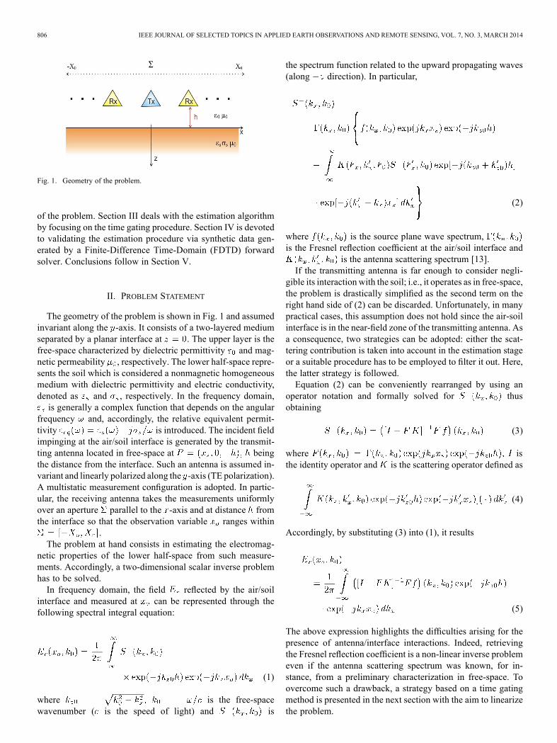
Fig. 1. Geometry of the problem.
of the problem. Section III deals with the estimation algorithmby focusing on the time gating procedure. Section IV is devotedto validating the estimation procedure via synthetic data gen-erated by a Finite-Difference Time-Domain (FDTD) forwardsolver. Conclusions follow in Section V.
II. PROBLEM STATEMENT
The geometry of the problem is shown in Fig. 1 and assumedinvariant along the -axis. It consists of a two-layered mediumseparated by a planar interface at . The upper layer is thefree-space characterized by dielectric permittivity and mag-netic permeability , respectively. The lower half-space repre-sents the soil which is considered a nonmagnetic homogeneousmedium with dielectric permittivity and electric conductivity,denoted as and , respectively. In the frequency domain,is generally a complex function that depends on the angular
frequency and, accordingly, the relative equivalent permit-tivity is introduced. The incident fieldimpinging at the air/soil interface is generated by the transmit-ting antenna located in free-space at beingthe distance from the interface. Such an antenna is assumed in-variant and linearly polarized along the -axis (TE polarization).A multistatic measurement configuration is adopted. In partic-ular, the receiving antenna takes the measurements uniformlyover an aperture parallel to the -axis and at distance fromthe interface so that the observation variable ranges within
.The problem at hand consists in estimating the electromag-
netic properties of the lower half-space from such measure-ments. Accordingly, a two-dimensional scalar inverse problemhas to be solved.In frequency domain, the field reflected by the air/soil
interface and measured at can be represented through thefollowing spectral integral equation:
(1)
where is the free-spacewavenumber ( is the speed of light) and is
the spectrum function related to the upward propagating waves(along direction). In particular,
(2)
where is the source plane wave spectrum,is the Fresnel reflection coefficient at the air/soil interface and
is the antenna scattering spectrum [13].If the transmitting antenna is far enough to consider negli-
gible its interaction with the soil; i.e., it operates as in free-space,the problem is drastically simplified as the second term on theright hand side of (2) can be discarded. Unfortunately, in manypractical cases, this assumption does not hold since the air-soilinterface is in the near-field zone of the transmitting antenna. Asa consequence, two strategies can be adopted: either the scat-tering contribution is taken into account in the estimation stageor a suitable procedure has to be employed to filter it out. Here,the latter strategy is followed.Equation (2) can be conveniently rearranged by using an
operator notation and formally solved for thusobtaining
(3)
where isthe identity operator and is the scattering operator defined as
(4)
Accordingly, by substituting (3) into (1), it results
(5)
The above expression highlights the difficulties arising for thepresence of antenna/interface interactions. Indeed, retrievingthe Fresnel reflection coefficient is a non-linear inverse problemeven if the antenna scattering spectrum was known, for in-stance, from a preliminary characterization in free-space. Toovercome such a drawback, a strategy based on a time gatingmethod is presented in the next section with the aim to linearizethe problem.
SOLIMENE et al.: ESTIMATION OF SOIL PERMITTIVITY IN PRESENCE OF ANTENNA-SOIL INTERACTIONS 807
III. TIME GATING
As already stated, the antenna/interface interactions candegrade the performance of Fresnel reflection coefficient (andhence soil permittivity) estimation. This is the case also for themultiple reflections occurring within the antenna itself.First, let us assume that the antenna is matched, i.e., there are
no internal multiple reflections so that we can focus on antenna/interface interactions. It is intuitively clear that the first contri-bution to the reflected field is due to “direct” reflection path (i.e.,transmitting antenna-interface-receiving antenna). Further con-tributions related to multiple interactions between the transmit-ting antenna and the soil are delayed in time and hence theycan be cut-off by a properly windowing in time. To accomplishthis task, let us consider the reflected spatial spectrum in (3),which accounts for the multiple bounces between the antennaand the interface. As the operator satisfies the inequality
(where is the norm), thencan be represented in terms of its Neumann series. This pointcan be shown analytically by invoking the energy conservationprinciple but can be easily understood since and theoperator scatterers back only a fraction of incoming field en-ergy. Accordingly,
(6)
with . By substituting (6) in (5), it results
(7)
In particular, the zero order term is given by
(8)
i.e., the field that would be reflected by the interface if the an-tenna/interface coupling did not occur.It is now clear that higher order terms in (7) must be “filtered
out” from data to restore linearity without introducing modelerrors which would compromise estimation accuracy. To meetthis goal, consider the first higher order term in (7), i.e.,
(9)
and introduce the time domain versions of andgiven by the inverse Fourier transforms
(10)
By exploiting (8), (4) and (9), it results
(11)
(12)
where and are the Fourier trans-forms, with respect to the angular frequency , of
and is the angular variable sothat and denotes the time domain convolution.As expected, the two contributions (11) and (12) have differentdelays, defined by the following formulas:
(13)
Accordingly, for the configuration at hand, the reflected fieldover each observation position starts to be collected at time
, whereas the first high-order reflection
arrives at , i.e.,
(14)
(15)
Therefore, multiple antenna interface reflections can be elimi-nated by gating the reflected field as follows
(16)
Equation (16) allows gating out not only high order couplingterms but also the direct coupling between transmitting and re-ceiving antenna whose time of arrival is lower than .It must be stressed that when the antennas are very close to
the air-soil interface, the time interval suitable for gating hasa shorter duration, thus limiting the applicability of the model.However, as long as the first returns do not overlap to successivemultiples the method can be applied as well.
808 IEEE JOURNAL OF SELECTED TOPICS IN APPLIED EARTH OBSERVATIONS AND REMOTE SENSING, VOL. 7, NO. 3, MARCH 2014
At this point, let us relax the assumption concerning thematching at the input terminals of the transmitting antenna.In such a case, part of the field reflected from the interfacereaches the transmitting antenna, re-enters the structure and isretransmitted towards the interface. The process repeats untilthese multiple scattering contributions become extinct. In anycase, they certainly arrive at the receiver after the time ,hence, it can be concluded that time gating in (16) effectivelyremoves these effects as well.Accordingly, we can consider only the zero order term in (8)
(17)
It is of crucial importance to note that the mismatch of transmit-ting antenna also entails the occurrence of multiple reflectionswithin the antenna. Therefore, the antenna plane-wave spectrumactually writes as
(18)
where the various contributions to the source spectrum arerelated to the internal reflections. Of course, if the internal prop-agation path is longer than , these contributions are alreadyfiltered out in data by the time-gating in (15). In such a case, theactual model to be used for soil estimation reduces to
(19)
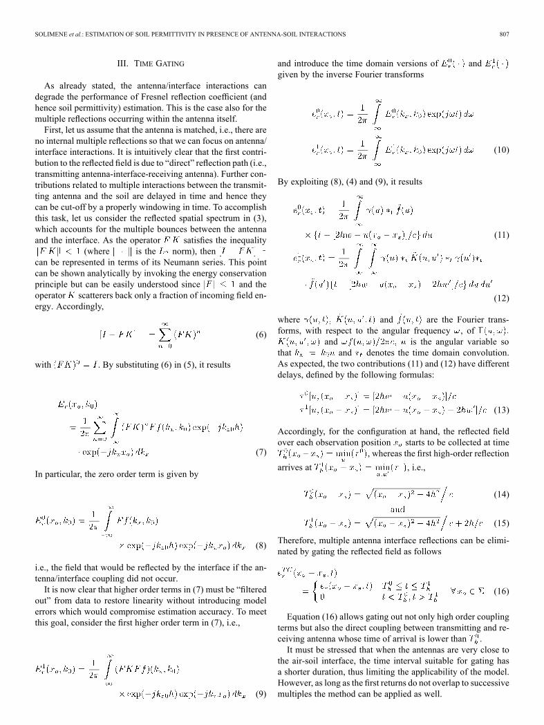
This entails that and not enters in the def-inition of the kernel of the relevant linear operator to be in-verted to recover the Fresnel coefficient. Accordingly, the an-tenna plane-wave spectrum can be conveniently determined viaa Fourier transform of a time-gated version of the field radi-ated by the antenna over the measurement line in free-spaceto be used for antenna spectrum calculation. Specifically, withreference to the antenna geometry sketched in Fig. 2, denotewith the distance between the measurement line (for spec-trum calculation) and the actual antenna feeding point. For eachobservation position , the transmitted signal starts to be re-ceived after time , defined according to the fol-lowing expression:
(20)
Then, by considering an additional time equal to pulse duration, the incident field is gated as follows
(21)
with .After this time-gating, the source spectrum is ob-
tained as a double Fourier transform with respect to time andobservation variable .
Fig. 2. Sketch of the antenna geometry.
Note that in (19), the receiving antenna is treated as an idealprobe since the focus of the paper is on the time gating proce-dure. The receiving probe characteristics, which are surely im-portant in real scenarios, can be dealt with in a straightforwardmanner as done in [14] and [15].Eventually, the problem at hand is cast as the inversion of
the linear integral equation (19) with respect to the unknown re-flection coefficient . Such a problem is ill-posed and aregularized solution is obtained via a Truncated-Singular-Value-Decomposition (TSVD) scheme [16]. In particular, denotingwith , the singular system of the operator in(19), the regularized solution is computed as
(22)
where is the truncation index determining the degree ofregularization.It must be stressed that (22) allows to retrieve the Fresnel co-
efficient as a function of the spectral angular variable and ata fixed frequency . If more frequencies are needed, as usuallyoccurs while applying imaging algorithms, the TSVD procedureoutlined above must be repeated for each frequency, separately.Once has been computed, it is used to determine
the electromagnetic properties (dielectric permittivity and con-ductivity) via a simple algebraic relation. In particular, for thecase at hand of TE polarization, it results
(23)
Note that, for a homogeneous medium, the dielectric permit-tivity is a constant that does not vary with the spectral variable. However, due the effect of the noise and regularization of
the TSVD scheme, only an estimation of the exact reflectioncoefficient is available thus, according to (23), necessarilydepends on . This drawback is mitigated by approximatingthe dielectric permittivity as the average of , i.e.,
(24)
where .
SOLIMENE et al.: ESTIMATION OF SOIL PERMITTIVITY IN PRESENCE OF ANTENNA-SOIL INTERACTIONS 809
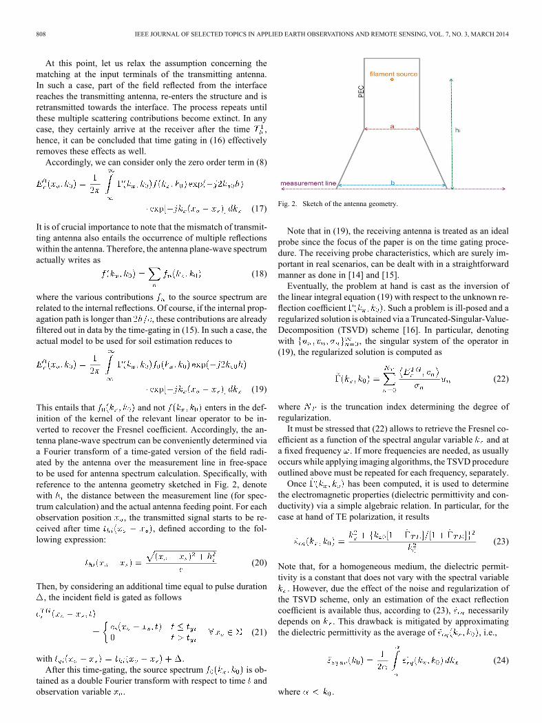
Fig. 3. Time domain electric field calculated via FDTD on 51 points in the case of a horn antenna. Top: free-space incident field;(a) before time gating and (b) after time gating. Bottom: reflected field by an half-space with ; (c) before time gating and (d) after time gating.
It is timely to remark that the reconstruction is notaccurate when approaches . Accordingly, the evaluationof the average permittivity in (24) is carried out only in a subset
of the visible range . In the following numer-ical analysis, the value of is set to .
IV. NUMERICAL RESULTS
Numerical results based on synthetic data generated by aFDTD forward solver [17] are reported in this section. Asshown in Fig. 2, the transmitting antenna is a parallel platewaveguide with PEC backing and having width mthat increases up to m so to mimic the section of ahorn antenna. The aperture is located at with
m. The reflected field is collected over the aperturem located at the same quota of the transmitting
antenna and with a spatial step of 4 cm (51 observation points).
The feeding point of the antenna is m far fromthe measurement line. The homogeneous half-space to beinvestigated is lossless with permittivity .Fig. 3 depicts the time domain incident fields (panels a and
b) and the reflected ones (panels c and d), as function of theobservation point, before and after the application of the timegating procedure. As can be seen in the panel c, the reflectedfield has a time duration larger than the incident one (panel a)due to the multiple antenna/soil interactions.Then, the gating procedure defined by (16) and (21) is applied
producing the incident and reflected fields shown in panels band d, respectively. Note that only the contribution of the directreflection from the interface is retained in Fig. 3(d).After time gating, the TSVD-based inversion procedure is
applied and the Fresnel reflection coefficient is calculatedat the frequency GHz as shown in Fig. 4(a). Here, the

810 IEEE JOURNAL OF SELECTED TOPICS IN APPLIED EARTH OBSERVATIONS AND REMOTE SENSING, VOL. 7, NO. 3, MARCH 2014
Fig. 4. The Fresnel reflection coefficient at GHz, module (top)and phase (bottom): actual one (red line) estimated one (blue line). The panel(a) refers to the estimation with the application of time gating. The panel(b) shows the estimation without time gating.
reconstructed Fresnel reflection coefficient is compared to thetrue one and, unlike Fig. 4(b) where the time gating processingis not carried out, the agreement (in amplitude and phase) issignificantly improved.The necessity of the time gating is more evident when eval-
uating the permittivity at multiple frequencies within the band[2, 2.8] GHz (see Fig. 5). This figure clearly highlights the im-provement in the accuracy of dielectric permittivity estimationwhen the inversion is performed after applying the time gatingprocedure.The estimation method has been tested also in other two cases
whose reconstruction results are presented only in terms of per-mittivity. The first results refer to a homogeneous medium withrelative permittivity equal to 4 (see Fig. 6). The estimation hasbeen made at 11 frequencies uniformly spaced in the frequencyinterval [1, 2] GHz.
Fig. 5. Soil relative permittivity . Green points represent the true value,the blue line is the estimation with time gating, and the red line concerns theestimation without time gating.
Fig. 6. Soil relative permittivity . Blue line is the true value, red lineis the estimation with the time gating procedure; green line is the estimationachieved without the time gating.
Finally, the case of equivalent dielectric permittivity varyingin frequency according to the Debye model has been dealt with,i.e.,
(25)
where S/m, ns. Figs. 7(a)and (b) depict the estimation of the real and imaginary partsof the equivalent dielectric permittivity, respectively, and againit is possible to appreciate the crucial role played by the timegating procedure on the reconstruction accuracy.
V. CONCLUSION
The estimation of soil’s electromagnetic parameters for sub-surface imaging applications has been dealt with in presence ofantenna/soil coupling. A time gating method has been adoptedto overcome this issue and the proposed strategy has been testedfor a two-layered background medium where the upper layerwas representative of the air whereas the lower one schematized

SOLIMENE et al.: ESTIMATION OF SOIL PERMITTIVITY IN PRESENCE OF ANTENNA-SOIL INTERACTIONS 811
Fig. 7. Soil relative permittivity varying according the Debye model. Blue lineis the true value, red line is the estimation with the time gating procedure; greenline is the estimation achieved without the time gating. Panel (a) real part ofthe equivalent dielectric permittivity; panel (b) imaginary part of the equivalentdielectric permittivity.
the soil. An estimation scheme based on a frequency domain in-tegral relationship linking the reflected field and the reflectioncoefficient at the air-soil interface has been adopted. Such a re-lationship has been inverted by means of a TSVD regularizationscheme. Afterward, the reflection coefficient and, hence, the di-electric permittivity of soil have been estimated. The effective-ness of the proposed time-gating strategy has been assessed bynumerical experiments.
REFERENCES
[1] D. Daniels, Ground Penetrating Radar, 2nd ed. London, U.K.: IEEPress, 2004.
[2] F. Soldovieri and R. Solimene, “Ground penetrating radar subsurfaceimaging of buried objects,” in Radar Technology. Vienna, Austria:IN-TECH, 2009.
[3] R. Persico and F. Soldovieri, “Effects of uncertainty on backgroundpermittivity in 1D linear inverse scattering,” J. Optical Society ofAmerica A, vol. 21, pp. 2334–2343, 2004.
[4] L. W. Galagedara, G. W. Parkin, and J. D. Redman, “An analysis ofthe ground-penetrating radar direct ground wave method for soil watercontent measurement,” Hydrol. Process., vol. 17, pp. 3615–3628,2003.
[5] J. Huisman, S. Hubbard, J. Redman, and A. Annan, “Measuring soilwater content with ground penetrating radar: A review,” Vadose ZoneJ., vol. 2, pp. 476–491, 2003.
[6] S. Lambot, J. Rhebergen, I. Van den Bosch, E. C. Slob, and M. Van-clooster, “Measuring the soil water content profile of a sandy soil withan off-ground monostatic ground penetrating radar,” Vadose Zone J.,vol. 3, pp. 1063–1071, 2004.
[7] S. Lambot, L. Weihermüller, J. A. Huisman, H. Vereecken, M. Van-clooster, and E. C. Slob, “Analysis of air-launched ground-penetratingradar techniques to measure the soil surface water content,”Water Re-sources Res., vol. 42, p. W11403, 2006.
[8] S. Lambot, E. Slob, D. Chavarro, M. Lubczynski, and H. Vereecken,“Measuring soil surface water content in irrigated areas of SouthernTunisia using full-waveform inversion of proximal GPR data,” NearSurface Geophys., vol. 6, pp. 403–410, 2008.
[9] D. A. Robinson, “Measurement of the solid dielectric permittivity ofclay minerals and granular samples using a time-domain reflectometryimmersion method,” Vadose Zone J., vol. 3, pp. 705–713, 2004.
[10] A. P. Annan, “Ground Penetrating Radar Workshop Notes,” SensorsSoftware, Mississauga, ON, Canada, 2001.
[11] J. Deparis and S. Garambois, “On the use of dispersive APVO GPRcurves for thin-bed properties estimation: Theory and application tofracture characterization,,” Geophysics, vol. 74, pp. J1–J12, 2009.
[12] R. Solimene, F. Soldovieri, and A. D’alterio, “Determination of theFresnel reflection coefficient of a half-space for medium estimationpurposes,” PIER B, vol. 27, pp. 61–82, 2011.
[13] P. Meincke and T. B. Hansen, “Plane-wave characterization of an-tennas close to a planar interface,” IEEE Trans. Geosci. Remote Sens.,vol. 42, pp. 1222–1232, 2004.
[14] A. D’Alterio and R. Solimene, “Accounting for antenna in half-spaceFresnel coefficient estimation,” Int. J. Geophys., vol. 2012, p. 11, 2012,Article ID 138458.
[15] F. Soldovieri, R. Persico, and G. Leone, “Effect of source and receiverradiation characteristics in subsurface prospecting within the distortedborn approximation,” Radio Sci., vol. 40, no. 3, p. RS3006, 2005.
[16] M. Bertero and P. Boccacci, Introduction to Inverse Problems inImaging. Bristol, U.K.: IOP, 1998.
[17] A. Giannopoulos, GprMax, A Ground Penetrating Radar SimulationTool. [Online]. Available: http://www.gprmax.org
Raffaele Solimene received the Laurea degree inelectronic engineering (summa cum laude) from theSeconda Università di Napoli (SUN), Aversa, Italy,in 1999. In 2001 he was the scientific responsibleof the project “Giovani ricercatori” funded by theMURST and entitled “Analysis of the resolution intomographic reconstructions”. In 2003 he earned thePh.D. in electronic engineering at SUN presentinga dissertation entitled “Resolution in linear tomo-graphic reconstructions”.In 2002 he became Assistant Professor at the Fac-
ulty of Engineering of the University Mediterranea of Reggio Calabria, ReggioCalabria, Italy. Since 2006, he has been with first the Dipartemento di Ingegneriadell’Informazione and then with the Dipartimento di Ingegneria Industriale edell’Informazione at SUN. Since 2013 he has been the principal investigatorof the project FIRB-MICENEA funded by Italina Ministry of University andResearch. His research activities focuses on noninvasive electromagnetic diag-nostics. In particular, he has tackled theoretical and numerical aspects pertainingelectromagnetic inverse scattering problems with reference to non-destructivesubsurface investigations, through-the-wall imaging and breast cancer detec-tion. On these topics he has co-authored more than 130 scientific works.
Antonietta D’Alterio, received the Laurea degree(summa cum laude) in electronic engineering fromthe Seconda Università di Napoli (SUN), Aversa,Italy, in 2009. Since then, she has joined the researchgroup in Applied Electromagnetic Fields of SUNas a Ph.D. student in electronic engineering. Hermain research interests include inverse scatteringproblems, microwave imaging, background mediumcharacterization in ground penetrating radar applica-tions and biomedical imaging.
812 IEEE JOURNAL OF SELECTED TOPICS IN APPLIED EARTH OBSERVATIONS AND REMOTE SENSING, VOL. 7, NO. 3, MARCH 2014
Gianluca Gennarelli was born in Avellino, Italy,in 1981. He received the M.S. degree (summa cumlaude) in electronic engineering and the Ph.D.degree in information engineering from the Univer-sity of Salerno, Fisciano, Italy, in 2006 and 2010,respectively.He held a Post-Doctoral Fellowship with the
University of Salerno from April 2010 to December2011. Since January 2012, he has been a ResearchFellow with IREA-CNR, Napoli, Italy. His currentresearch interests include theoretical and applied
electromagnetic topics such as microwave sensors, radar imaging techniques,high frequency scattering problems, near-field far-field transformation tech-niques, and electromagnetic simulation.
Francesco Soldovieri (M’10–SM’12) received theLaurea degree in electronics engineering from theUniversity of Salerno, Salerno, Italy, in 1992 andthe Ph.D. degree in electronics engineering from theUniversity of Naples “Federico II,” Naples, Italy, in1996.In 1993, he joined the Electromagnetic Research
Group, University of Naples, and in 1998–1999, heheld a Postdoctoral Fellowship with the same univer-sity. In 2001, he joined the Institute for Electromag-netic Sensing of the Environment of the Italian Na-
tional Research Council (IREA-CNR), Naples, as a Researcher, where he hasbeen a Senior Researcher since 2006. His main scientific interests include elec-tromagnetic diagnostics, inverse scattering, GPR applications, antenna diagnos-tics and characterization, and security applications.Dr. Soldovieri was the General Chair of the International Workshop on Ad-
vanced Ground Penetrating Radar 2007. Since 2002, he has been involved inthe Technical Committees of the GPR Conference and IWAGPRWorkshop. Hehas been a Special Guest Editor for issues of the Journal of Applied Geophysics,Near Surface Geophysics, and Advances in Geosciences. He was awarded the1999 HonorableMention for the H. A.Wheeler Applications Prize Paper Awardof the IEEE Antennas and Propagation Society.