establishing reliability in vibration measurement and its
TRANSCRIPT

Research paper
−47−Synthesiology - English edition Vol.10 No.2 pp.47 –61 (Feb. 2018)
earthquakes, the accelerometer used in inertial navigation of aircraft, and the acceleration sensor installed in smart phones are also vibrometers.
On the other hand, as it can be projected from Fig. 1, while the mass can stay at a fixed point as long as the vibration amplitude is small enough, the mass will not be able to stay at the fixed point due to the restoring force of the spring when the vibration surpasses a certain level. Such a property is determined by the stiffness of the spring, the natural vibration when considered as a mass-spring model, and the viscous element (damping) that absorbs vibration though this is abbreviated in Fig. 1. The vibrometer manufacturers optimize the above parameters for specific uses such as measurement of earthquakes, vibration of structures such
1 Introduction
1.1 Outline of the vibration measurement and the necessity of calibrationVibration is closely connected to human physiology and living conditions through natural phenomena such as earthquakes as well as industrial products including buildings, aircraft, railways, and automobiles. Also, vibration in machines may reduce their functions and cause failure, and may lead to problems in occupational safety or accidents. Vibration measurement was positioned as important technology from the early stage of mechanical technology, and its importance is increasing as humans enjoy the benef its of science and technology while maintaining safe and comfortable environment.
The person (or device) conducting vibration measurement must be placed at a point from which it does not move within the spatial coordinate (the fixed point). As shown in Fig. 1, such a fixed point can be simulated by a seismic system consisting of a spring and a mass. The mass keeps its place (fixed point) against vibration due to inertia. By detecting the relative displacement between the mass and the object, or the inertial force acting on the mass, it is possible to measure the quantity of vibration. In the actual detection mechanism, various elements are involved such as conductive coils (displacement), strain gauges (strain), and load cells (force). In this paper, we shall generally call such a seismic system vibration detector as a vibrometer. The seismometer for
- Development of national metrology standards for vibration, acceleration, shock measurement and progress on international comparisons-
The metric system and primary national metrology standards are necessary, but not sufficient for obtaining measurement equivalency. Recently, national metrology institutes of various countries including NMIJ/AIST of Japan are participating in international comparisons to confirm equivalency of their measurement capabilities, under a mutual recognition of arrangement (MRA). In this report, we describe progress on improving vibration measurement at NMIJ/AIST, along with global activities for establishing MRA. We also discuss future issues for improving vibration measurement.
Establishing reliability in vibration measurement and its international equivalency
Keywords : Vibration, acceleration, shock, calibration, metrology standard, equivalency evaluation, inter comparison, international standardization
[Translation from Synthesiology, Vol.10, No.2, p.50–62 (2017)]
Takashi Usuda1*, Akihiro Oota2, Hideaki Nozato2 and Wataru Kokuyama2
1. Research Promotion Division, National Metrology Institute of Japan, AIST Tsukuba Central 3, 1-1-1 Umezono, Tsukuba 305-8563, Japan * E-mail: , 2. Research Institute for Engineering Measurement, National Metrology Institute of Japan, AIST Tsukuba Central 3, 1-1-1 Umezono, Tsukuba 305-8563, Japan
Original manuscript received December 14, 2016, Revisions received February 26, 2017, Accepted February 27, 2017
Measurement subject
Mass
Spring
Acceleration scale
Fig. 1 Seismic system vibrometer

Research paper : Establishing reliability in vibration measurement and its international equivalency (T. Usuda et al.)
−48−
Synthesiology - English edition Vol.10 No.2 (2018)
as bridges or buildings, mechanical vibration, or collision phenomena (Fig. 2).
Whether a vibrometer has the property as designed must be checked by calibration. Calibration can be achieved by applying vibration of arbitrary frequency to a vibrometer, and then measuring the displacement with a laser interferometer and, at the same time, measuring the electric output from the vibrometer. The calibration result is given as the electric output against the unit vibration input (displacement, velocity, or acceleration). Figure 3 shows such a calibration device for a vibrometer.[1] Needless to say, the entire calibration device must be thoroughly vibration-isolated to prevent any effect of extraneous vibrations.
Calibration using such a laser interferometer is called primary calibration because it is linked directly to the definition of length. Conducting relative calibration of other vibrometers
using a primary-calibrated vibrometer as the reference standard is called secondary calibration. A vibrometer that is primary-calibrated at AIST becomes the standard for vibrometer production companies and private calibration laboratories, and many vibrometers will undergo secondary calibration. Secondary-calibrated vibrometers are used in various kinds of application such as in vibration tests or in seismometers. The unbroken connection between the national standards and on-site vibrometers through calibration is called measurement traceability (Fig. 4).
1.2 Activities around international consistency for measurement and the responses of JapanSince the 1990s, with the end of the Cold War and the integration of Europe as the European Union, globalism accelerated, and there was demand for the internationalization of technological standards that were applied within each nation. In 1995, under the World Trade Organization (WTO),
Time response FastSlow
Acceleration
Low
High
Aerospace
Vessels (power)Earthquake resistance inspection for nuclear power plants
(collision safety, air bags)(engine,
transportation test)
Development of sports goods, etc.Bridges, public
buildings (vibration tolerance)
SeismometersEarthquake observation
Buildings (vibration control, aseismic base isolation)
Factories, plants (facility diagnosis)
Hard discs (head protection)
Nanotech, semiconductors (microfabrication
control)
Automobiles, railways
Sine wave shaker
Moving parts
Laser
Reference mirror
Beam splitter (half mirror)
Photo detector
Vibrometer
Reflective mirror
Measurement & control system
Vibration direction
Primary calibration
Secondary calibration
Secondary-calibrated vibrometer
Vibration test
Seismometer Shock test
Vibrator
Vibrator
Primary-calibrated vibrometer
Fig. 2 Fields in which vibration measurement is in demand and the characteristics of vibrations
Fig. 3 Vibrometer calibration device Fig. 4 Traceability in vibrometer calibration
Research paper : Establishing reliability in vibration measurement and its international equivalency (T. Usuda et al.)
−49−Synthesiology - English edition Vol.10 No.2 (2018)
the Agreement on Technical Barriers to Trade (TBT) was concluded, and countries were required to set technological standards, as exemplified by the international standards of the International Organization for Standardization (ISO) and the International Electrotechnical Commission (IEC), and they had to mutually recognize such standards. For measurement standards, from a system where traceability[2] was maintained by the national metrology institute (NMI) who establishes national primary standards, the shift was made to a system of evaluating the equivalency of national measurement standards under the Metre Convention. In 1999, a memorandum for Mutual Recognition Arrangement (called the CIPM-MRA, adding the acronym for Comité International des Poids et Mesures that drafted the memorandum)[3] was signed, to conduct equivalency evaluation by international comparison and to publish the results.
The types and ranges of international comparison necessary for equivalency evaluation were to be discussed by the Consultative Committee consisting of the Metre Convention members. For vibration, the Consultative Committee for Acoustics, Ultrasound and Vibration (CCAUV) was established in 1998,[4] and the first discussions for international comparison for vibrometers began.
Until about the middle of the 1990s, the calibration of vibrometers at the Japanese NMI (at the time, it was the National Research Laboratory of Metrology, the Agency of Industrial Science and Technology) was conducted only for low vibration frequency (4 to 90 Hz; later revised to 80 Hz) for environmental assessment to measure ground vibration under construction, and the users and manufacturers of other fields conducted their own calibration. At the National Research Laboratory of Metrology, the “Review Committee for Traceability of Vibration and Acceleration” (hereinafter, the Review Committee) for vibrometers was organized by 13 Japanese companies starting in FY 1995. For two years and a half, the Review Committee conducted a survey of the demand for calibration. As a result, it was agreed that due to the necessities for vibration tests, automobile collision tests, and others, in addition to the conventional 80 Hz ceiling as the national standard for vibrometer calibration, vibration frequency range up to 5 kHz and acceleration amplitude of 1–100 m/s2 should be set as quickly as possible. It was also recognized that phase lags (phase shift character) of vibration accelerometer output was an important reference value.
In this paper, the development of a vibrometer calibration method in Japan and the international movement in equivalency evaluation will be discussed, setting 1995 as a starting point. The configuration of the paper is as follows.
In Chapter 2, the establishment of the national standard for vibrometer calibration up to 5 kHz that was accomplished by 2000 and the response to the first international comparison
will be explained.
In Chapter 3, the establishment of the national standard for vibrometer calibration up to 10 kHz and the response to the second international comparison that was conducted around 2010 will be explained.
In Chapter 4, the establishment of the national standard for vibrometer calibration up to 0.1 Hz and the response to the third international comparison that was conducted around 2015 will be explained.
In Chapter 5, the establishment of the national standard for shock calibration and the equivalency evaluation to centrifuge acceleration calibration will be explained.
Chapter 6 will be the summary of this paper and future prospects.
2 Establishment of the national standard for vibrometer calibration up to 5 kHz and the response to the first international comparison
In this chapter, the establishment of the national standard for vibrometer calibration up to 5 kHz that was agreed upon by the Review Committee and the response to the first international comparison will be explained.
2.1 Scenario for the R&DThe laser interferometer used as the calibration device shown in Fig. 3 is called the Michelson type, and is the most basic format for displacement measurement. The light emitted from the laser source has coherent wavelength and phase. Its optical path is divided by a beam splitter, and the beams are introduced into the reference mirror and the vibrometer. A reflective mirror is installed at the edge of the vibrometer that is to be calibrated, and the displacement of the vibrometer can be measured as the optical path difference of the two beams. The interfering light intensity changes periodically for each 0.5 wavelength of an optical path difference, and this can be detected by an optical detector. Therefore, for example, if the helium-neon laser of wavelength of 632.8 nm is used as the light source, the interfering light intensity repeats the light-dark cycle every 316.4 nm, and the resolution at submicrometer level can be achieved relatively easily. Moreover, for the measurement of static displacement, it is possible to obtain higher resolution by interpolating the interfering light intensity, but it is difficult to obtain high resolution in the environment of vibration, which essentially is in conflict with making precise measurement.
On the other hand, since displacement, velocity, and acceleration are in calculus relationships with each other, if the vibration is in sine wave, the relationship with vibration frequency is as given in Fig. 5. At 5 kHz that was agreed

Research paper : Establishing reliability in vibration measurement and its international equivalency (T. Usuda et al.)
−50−
Synthesiology - English edition Vol.10 No.2 (2018)
Velocity m/s
0.001
0.01
0.1
1
Vibration frequency Hz10 k1 k 10010
100
1000
10
1
Acceleration m/s 2
Calibration range set as goal
Beam splitter
Vibration-isolated table
Reflective mirror
VibrometerMoving parts
Sine wave shaker
Interfering beam
Circular polarized beam
Linear polarized beam
Unpolarized beam
Measurement & control system
Photo detector
Wollaston prism(separates incident light into perpendicular linear polarizing beams)
Laser light source
¼ wavelength plate
Reference mirror
Polarizing plate
Polarizing plate
as the upper limit of the vibration frequency by the Review Committee, the displacement amplitude will be about 100 nm (at acceleration amplitude of 100 m/s2), and the improvement of the resolution is essential.
However, in the vibration environment, the interfering light intensity itself fluctuates due to the shift of the optical axis arising from vibration, and it is not possible to increase the resolution by interpolating the intensity as it can be done for static displacement measurement. Also, the information obtained from the interferometer shown in Fig. 3 is only for amplitude, and this does not allow the evaluation of the output difference (phase) from the vibrometer and the vibration in the time domain.
The technological goal is to achieve calibration of vibration at acceleration amplitude of 1–100 m/s2 up to a vibration frequency range of 5 kHz, along with phase property evaluation. In conducting the equivalency evaluation by international comparison, it is necessary to conduct uncertainty evaluation. It is also necessary for the system to have robustness and stability that can withstand the rigors of routine calibration work.
2.2 Selection and development of the elemental technologiesThe calibration device is mainly composed of the following:
• Laser interferometer• Vibrator• Controller and electric measurement system
Of these, it was mandatory to newly develop the laser interferometer due to the necessity for phase shift evaluation and the required calibration range. On the other hand, since it was difficult to develop a mechanical element of a vibrator with reliability and durability in a short time, we used a commercially available product for which the evaluation was established at the time (we used an electrodynamic vibrator in which the moving parts were supported by leaf springs). Since the performance of interface and personal computers (PC) have improved rapidly, a PC was used as the controller, a multipurpose voltmeter and a frequency counter were used for an electric measurement system, and the system could be sufficiently flexible to meet the demands for future performance improvement. Needless to say, it was necessary to prepare and evaluate the calibration environment such as control of humidity and temperature, as well as a vibration isolation table that suff iciently eliminated extraneous vibration. Figure 6 shows the principle of the developed interferometer.
The interferometer is a modified Michelson type. The laser beam from the light source (He-Ne laser, wavelength of
Fig. 5 Relationship of displacement, velocity, and acceleration in sine wave vibration and their calibration range
Fig. 6 Developed laser interferometer
Research paper : Establishing reliability in vibration measurement and its international equivalency (T. Usuda et al.)
−51−Synthesiology - English edition Vol.10 No.2 (2018)
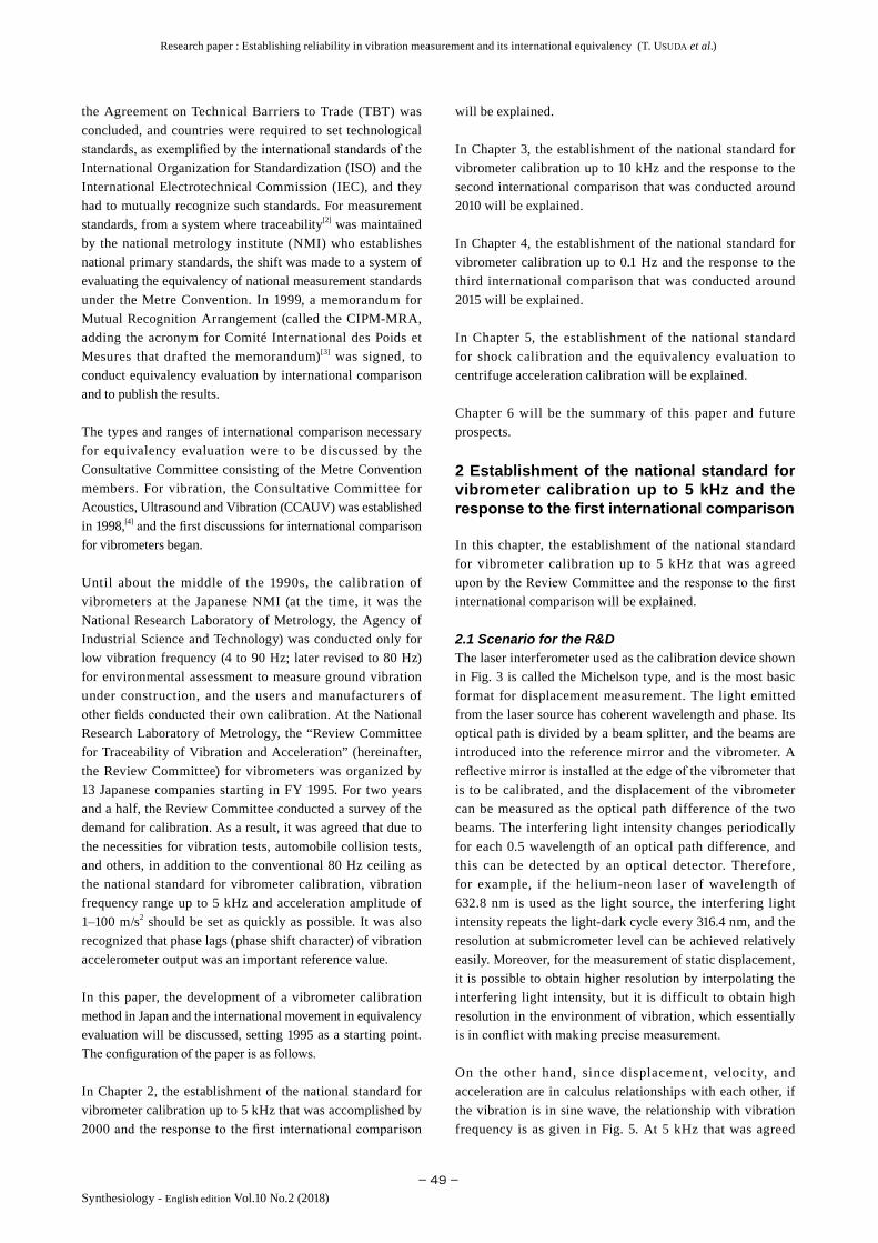
632.8 nm) is linearly polarized by a polarizing plate. Then, it passes through the 1/4 wavelength plate and becomes circular-polarized. Next, it is separated into a measurement beam and a reference beam by an unpolarized beam splitter. The reference beam is reflected by a reference mirror, and is linearly polarized by a polarizing plate. The measurement beam is ref lected by the ref lecting mirror installed at the edge of the vibrometer, and interferes with the reference beam. The Interfering light is separated by a Wollaston prism into a quadrature beam where the phase differs by 90°. The polarized beam components are detected by the two optical detectors.
Figure 7 shows the relationship between vibration acceleration and the detected interference signal. In circular polarization, an interference signal in the polarization direction that differs in phase by 90° is obtained, and therefore, when the vibrometer to be calibrated moves, the signals from the two optical detectors will be as shown in Fig. 7 right. As the vibration direction inverts, the output of the interferometer inverts and the vibration direction can be determined. By demodulating the two outputs with an appropriate algorithm,
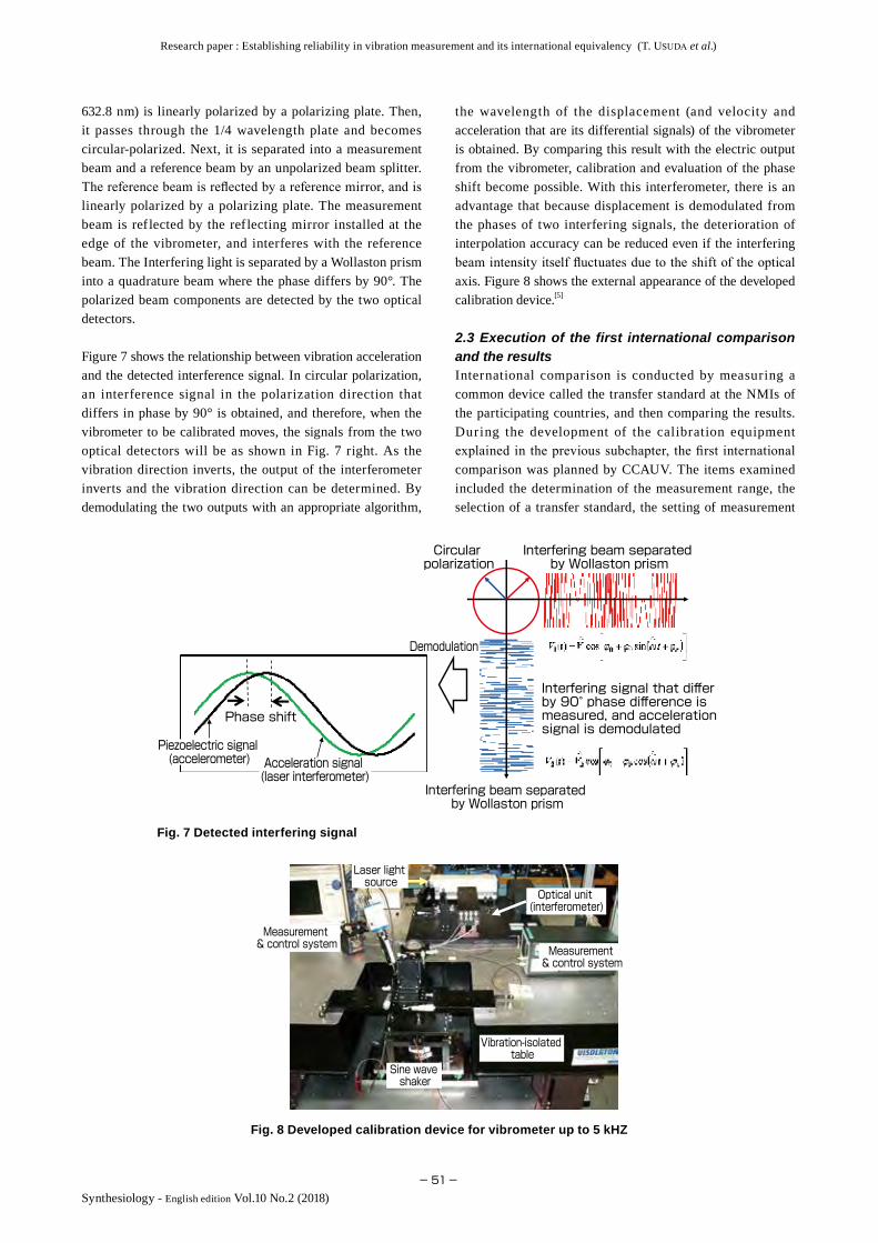
the wavelength of the displacement (and velocity and acceleration that are its differential signals) of the vibrometer is obtained. By comparing this result with the electric output from the vibrometer, calibration and evaluation of the phase shift become possible. With this interferometer, there is an advantage that because displacement is demodulated from the phases of two interfering signals, the deterioration of interpolation accuracy can be reduced even if the interfering beam intensity itself fluctuates due to the shift of the optical axis. Figure 8 shows the external appearance of the developed calibration device.[5]
2.3 Execution of the first international comparison and the resultsInternational comparison is conducted by measuring a common device called the transfer standard at the NMIs of the participating countries, and then comparing the results. During the development of the calibration equipment explained in the previous subchapter, the first international comparison was planned by CCAUV. The items examined included the determination of the measurement range, the selection of a transfer standard, the setting of measurement
Fig. 8 Developed calibration device for vibrometer up to 5 kHZ
Measurement & control system Measurement
& control system
Laser light source
Optical unit (interferometer)
Vibration-isolated table
Sine wave shaker
Interfering beam separated by Wollaston prism
Interfering beam separated by Wollaston prism
Circular polarization
Demodulation
Interfering signal that differ by 90° phase difference is measured, and acceleration signal is demodulated
Phase shift
Piezoelectric signal (accelerometer) Acceleration signal
(laser interferometer)
Fig. 7 Detected interfering signal

Research paper : Establishing reliability in vibration measurement and its international equivalency (T. Usuda et al.)
−52−
Synthesiology - English edition Vol.10 No.2 (2018)
conditions, the processing method of the measurement results, the preliminary adjustment of par t icipat ing institutes, and others. After the discussions at CCAUV, the Physikalisch-Technische Bundesanstalt (PTB), the German NMI, was entrusted to be the pilot laboratory that would be responsible for the management of the international comparison, and details were reviewed led by PTB. One of the authors was a visiting scientist to PTB at the time, and was able to participate in the discussions for determining the measurement conditions. The topic that became particularly important in the measurement conditions was the range of the vibration frequency. Some participating institutes requested measurement up to 10 kHz, but it was agreed to compare the measurement results up to 5 kHz only because the stability and high frequency characteristic of the transfer standard were not sufficiently investigated. The international comparison was conducted by 12 participating institutes from 2000 to 2001.[6] In this international comparison, the vibrometer with a piezoelectric element was employed as the transfer standard, and its sensitivity (piezoelectric output per unit output) was calibrated. Figure 9 shows the results of some of the participants in this international comparison.
The vertical axis shows the calibration value of the transfer standard, while the horizontal axis shows the vibration frequency. It is shown that the sensitivity increases due to the effect of the resonance vibration of the seismic system as the frequency increases. The measurement results of the participating institutes are processed statistically along with the uncertainty, and the key comparison reference value, which is the value estimated to have the highest certainty in this international comparison, is determined. If the measurement results of each participant fall in the reference value within the range of uncertainty, it will be proof of international equivalency. The calibration results of AIST was good. However, some participants showed deviation of 1 % or higher as shown in Fig. 9. Since the uncertainty at which the participating institutes conducted self-evaluation was around 0.5 %, this result forced the total review of the
calibration equipment for some NMIs. Also, since there was a tendency that the deviation among participants increased at a higher vibration frequency, the necessity of an international comparison at a higher frequency was recognized.
3 Establishment of the national standard for vibrometer calibration up to 10 kHz and the response to the second international comparison
When the first international comparison was conducted, the Measurement Standards and Intellectual Infrastructure Plan was created under the 2nd Science and Technology Basic Plan (approved by the Cabinet on March 30, 2001), and the world’s highest level intellectual infrastructure was to be organized by about 2010. The organization of the metrology standard was assigned to the National Metrology Institute of Japan, AIST. For the calibration of the vibrometer, since the vibration measurement of 5 kHz or more was being done in industry, the goal was set at the establishment of a national standard up to 10 kHz. In this chapter, the establishment of the national standard for vibrometer calibration up to 10 kHz and the response to the second international comparison will be explained.
3.1 Scenario of the R&DAs shown in Fig. 5, when the vibration frequency applied to the vibrometer is increased, the displacement amplitude is inversely proportional to the square of the vibration frequency when the acceleration value is kept constant. Therefore, when the acceleration amplitude of 100 m/s2 is maintained, the displacement amplitude is 100 nm at 5 kHz, while it decreases to 25 nm that is 1/4 of that value at 10 kHz. Since such small displacement amplitude surpassed the calibration capacity of the device described in Chapter 2, a totally new laser interferometer was necessary. For the vibrator that generates motion, even linear vibration cannot be produced using an electrodynamic vibrator in which the moving parts are supported by conventional leaf springs, due
Fig. 9 An example of the results of the first international comparison for vibrometer calibration
100 10000.1255
0.1260
0.1265
0.1270
0.1275
0.1280
0.1285
0.1290
0.1295
0.1300
0.1305
0.1310
0.5 %1.0 %
1.5 %Deviation of participating institutes
AustraliaKoreaUSAJapanGermany (PTB)Netherlands
Vibrometer sensitivity (Acceleration
per piezoelectric output) [pC/(m/s2 )]
Vibration frequency (Hz)

Research paper : Establishing reliability in vibration measurement and its international equivalency (T. Usuda et al.)
−53−Synthesiology - English edition Vol.10 No.2 (2018)
to the effects of vibration strain and parasitic vibration.[7][8] Therefore, a new vibrator with superior stability, including a solid actuator such as a magnetostriction element became necessary. For an electric measurement system, reviews were done since advanced sampling was necessary. For calibration capacity, considering the requests from the Japanese industry and looking at the actual calibration conducted at advanced industrial countries such as Germany, the goal was set at expanded calibration uncertainty of 0.3 %–1.0 %.
3.2 Selection and development of elemental technologiesDue to the requirements mentioned in the previous subchapter, a totally new laser interferometer was developed. The technological characteristic was to double the optical path difference compared to the conventional one by introducing a catoptric system. Specifically, two types of laser interferometers, one with twofold optical paths and another with fourfold optical paths, were fabricated, and their properties and operabilities were investigated.[9] Figure 10 shows the optical arrangement and details of the optical path of the developed fourfold optical path laser interferometer.
The characteristic is, as shown in Fig. 10(a), that the resolution increases as the measurement beam introduced to the vibrometer is folded back four times through the fourfold optical path system. This is achieved by controlling and selecting the polarization direction of the beam by combining the optical elements, and the details are shown in Fig. 10(b). Laser beam that enters from (1) is separated into reference and measurement beams by the reflective and transmitting surfaces (2) of the polarizing beam splitter, and the measurement beam is reflected on the measurement surface (3) of the vibrometer. The reflected beam reflects off the reflective surfaces (4) (5) of the corner mirror, and then is reflected again on the measurement surface (6) of the vibrometer. The beam is reflected in numerical order as indicated in Fig. 10(b), is finally combined with the reference beam, and interference occurs.
Since the interfering beam output itself is detected as a
quadrature beam as shown in Fig. 7, it is possible to reproduce the vibration wavelength by appropriate demodulation. The major advantage of this interferometer is that a special reflective mirror such as a corner cube mirror is not necessary to measure the subject, and the optical path difference can be doubled with a flat-reflective mirror. In the vibration range of 10 kHz, all parts are subject to elastic deformation, and therefore it is desirable that the vibrating parts have simple structures as much as possible, and such a characteristic that allows simplif ication of the structure contributes greatly in reducing the uncertainty of calibration. When this interferometer was evaluated, it was confirmed that amplitude displacement up to 16 nm that greatly surpassed the planned 25 nm could be detected.
A twofold optical path laser interferometer was fabricated and evaluated similarly, and it was confirmed that amplitude displacement up to 25 nm could be detected as originally planned. Based on these results, considering the technical level of the calibration personnel and efficiency of work time when this technology was applied to actual calibration work, and reviewing the technological issues such as the S/N ratio of the interfering light signals and operability of the optical axis alignment, we decided to employ the twofold optical path laser interferometer.
For the vibrator, an electrodynamic vibrator, in which the moving parts are supported by leaf springs, just as in the calibration equipment for 5 kHz maximum that was developed in Chapter 2, and a piezoelectric vibrator, in which the moving parts are supported by solid actuators and air bearings, were considered as candidates. In this calibration condition where the vibration amplitude reaches several tens of nm level, the parasitic oscillation in the direction outside the intended vibration may reach a relatively non-negligible size in the leaf spring supported type, and this method was eliminated. The piezo and magnetostriction elements were strong candidates, but it was found that the strain in the vibration wavelength was large, and they were inappropriate
Fig. 10 Configuration of the developed laser interferometer and its optical path arrangement(a) Optical path arrangement diagram, (b) Optical path of measurement light
Fourfold optical path system
Corner mirror¼ wavelength plate
Reflective mirror
Beam splitter
Wollaston prism
Photo detector
Reflective mirror Reflective
mirror
Reflective mirror
Laser light source
Vibrometer
Moving parts
Sine wave shaker
(a)
Reference beam
Incident light
Emitted light
¼ wavelength plate
Polarizing beam splitter
Corner mirror 2
Corner mirror 1
(b)

Research paper : Establishing reliability in vibration measurement and its international equivalency (T. Usuda et al.)
−54−
Synthesiology - English edition Vol.10 No.2 (2018)
Measurement & system
Optical unit (interferometer, twofold optical path system)
Vibration-isolated table
Sine wave shaker
振動計感度の参照値からの偏差
(圧
電出
力毎
加速
度)
[pC
/(m/s
2 )]
ドイツ
チェコ
南ア
デンマーク
スペイン
ポーランド
スイス
日本
フランス 中
国
メキシコ
ブラジル
トルコ ロシア
参加国の結果-8
-6
-4
-2
0
2
4
6X10⁻³
偏差
1 %相
当Equivalent to 1 % deviation
6
4
2
0
-2
-4
-6
-8Results of participating countries
Russia
Turkey
BrazilMexico
China
France
Japan
Switzerland
Netherlands
Spain
Denmark
South Africa
Czech Republic
Germany
Deviation from reference value of
vibrometer sensitivity
(acceleration per piezoelectric output) [pC/(m/s2 )]
×10-3
for calibration. Finally, the electrodynamic vibrator where the moving parts are supported by air bearings was employed. The calibration equipment with maximum of 10 kHz thus developed is shown in Fig. 11.[10]
3.3 Execution of the second international comparison and the resultsAfter the first international comparison of the vibrometer calibration explained in Subchapter 2.3, CCAUV decided to conduct the second international comparison. From the necessity to evaluate the equivalency at a high vibration frequency, it was decided that the calibration range would be up to 10 kHz, and the phase shift of the vibrometer that was essential information in modal analysis and automatic control would also be evaluated and compared. The international comparison was conducted by 15 participating institutes from 2009 to 2012.[11] The pilot laboratory was PTB of Germany as in the first international comparison.
Figure 12 is an example of the calibration result at 10 kHz. In the figure, the key comparison reference value is set at the origin, and the deviation of participating NMIs is shown in the vertical axis. The error bars are the stated uncertainties
of NMIs. The size of deviation does not directly indicate the superiority of the NMIs, but compared to the f irst international comparison results where the deviation of participating NMIs reached several percent, the deviation of all institutes (except Russia) was about 1 %. Also, the values were mutually consistent in the uncertainty range, and it could be seen that the equivalency of calibration results of the countries was satisfied for a high vibration frequency range. On the other hand, in the process of measurement by participating institutes, it was observed that the sensitivity of the transfer standard changed (Fig. 12 is the result where such a change was corrected by regression analysis). The sensitivity change of the transfer standard is a problem that greatly damages the reliability of international comparison. Currently, CCAUV is engaging in discussions on the selection of an appropriate transfer standard and the handling of the transfer standard during transportation, in order to start a new international comparison after 2017.
4 Establishment of the national standard for vibrometer calibration up to 0.1 Hz and the response to the third international comparison
Chapters 2 and 3 mainly discussed the expansion of the calibration capacity to a high vibration frequency range. However, as shown in Fig. 2, vibrometers are used in observation of ear thquakes (in seismometers) and in monitoring the vibration of bridges and other structures. These vibrations may range from several tens of Hz to a low vibration frequency of about 0.1 Hz. Recently, it has been reported that although earthquake resistance of buildings increases, the low frequency (long-period) seismic waves lead to large shakes due to the introduction of f lexible structures in high-rise buildings. The vibrometer calibration at a low vibration frequency range is similarly important. In this chapter, the establishment of the national standard for such a low vibration frequency and the result and response to the third international comparison will be explained.
4.1 Scenario of the R&DThe topic of the reliability of the vibration measurement in a low vibration frequency range is particularly a matter of concern in Japan that is an earthquake prone country, and the introduction of calibration equipment to facilitate evaluation of seismometers has been done since the old National Research Laboratory of Metrology days. Figure 13 is the external appearance of such equipment. The moving parts supported by air bearings vibrate over 360 nm strokes by an electrodynamic linear motor.[12] As shown in Fig. 5, when the vibration frequency decreases, the acceleration generated decreases even if the same displacement amplitude is maintained, and the acceleration amplitude that can be generated by this equipment is in the range of 0.03 m/s2–20 m/s2. When the displacement at large amplitude is generated at such small acceleration, the strain of the acceleration
Fig. 11 Developed calibration device for vibrometer up to 10 kHz
Fig. 12 An example of the results of the second international comparison for vibrometer calibration

Research paper : Establishing reliability in vibration measurement and its international equivalency (T. Usuda et al.)
−55−Synthesiology - English edition Vol.10 No.2 (2018)
waveform becomes relatively large due to the non-uniformity of movement, and this increases the uncertainty of the calibration results. Therefore, generation of sine waves where the waveform strain is decreased to 1 % or less is achieved by employing air bearings that have extremely small friction. On the other hand, for the laser interferometer, the sensitivity of the vibrometer and phase assessment are made possible by basically using the modified Michelson interferometer as presented in Chapter 2.
4.2 Selection and development of elemental technologiesFor vibrometer calibration in a low frequency range, in general, only small acceleration can be generated due to the limitation of vibration strokes. The vibrometer output signal is small against the generated acceleration, the S/N ratio deteriorates, and this increases the uncertainty. Therefore, a digital filter, where the S/N ratio is increased and the uncertainty is decreased by filter-processing the obtained signal on the computer, was employed.[13]
Although the digital filter itself was not a new method, the calculation load was large because it was necessary to take in several gigabytes of data per session and conduct a demodulation process if one wished to obtain several dozen waveforms needed for filtering at 0.1 Hz (10 sec cycle). However, due to the increased capacity of computers in the past few years, the processing became possible in realistic time.
Through a series of development and optimization, the performance of uncertainty of 0.15 % and phase shift of 0.05° was achieved at 0.1 Hz.
4.3 Execution of the third international comparison and the resultsOn the other hand, CCAUV was conducting international comparisons mostly in the high vibration frequency range.
This was because the high frequency range was the priority in industrial vibration measurement, and the low frequency vibrometers were mostly used in special cases such as in seismometers or in inertial navigation for aircraft. Also, such vibrometers could be converted to military use such as for intercontinental ballistic missiles, and it was considered not in the best interest for conducting international comparison.
Against such a background, there were earthquake related disasters in several countries including Japan, and there was a surge in interest for vibrometer calibration at a low frequency range. Also, after the establishment of CCAUV in 1998 and the following two international comparisons, there was increased interest in vibration measurement in the international community, as well as understanding for the importance of international comparisons. Therefore, the third international comparison where the minimum vibration frequency was set at 0.1 Hz was conducted from 2013 to 2015, using the low frequency vibrometer as a transfer device, and 14 NMIs participated.
Figure 14 shows an example of the international comparison results, and shows the equivalency among institutes for 0.1 Hz.[14] As in Fig. 12, the key comparison reference value is set at the origin, and the deviations of participating NMIs are shown in the vertical axis. The error bars are the stated uncertainties of each institute.
Of the 14 NMIs that participated, only eight institutes, including China, Germany, Denmark, South Africa, Mexico, Australia, Singapore, and Japan, were able to make the most difficult measurement of 0.1 Hz, and the other six institutes withdrew their data. The result submitted by AIST had the smallest uncertainty among the eight institutes, and was consistent with the key comparison reference value. However, the meaning of this result will be discussed at CCAUV in the future, including the stability of the transfer standard.
Laser interferometer
Moving parts of vibratorSine wave
shaker
Deviation from reference value
of vibrometer sensitivity
(acceleration per piezoelectric output) [V/(m/s2 )]
Results of participating countries
Equivalent to
1 % deviation
Singapore
Australia
JapanMexico
South America
Denmark
Germany
China
Fig. 13 Developed calibration device for vibrometer with minimum frequency 0.1 Hz
Fig. 14 An example of the results of the third international comparison for vibrometer calibration

Research paper : Establishing reliability in vibration measurement and its international equivalency (T. Usuda et al.)
−56−
Synthesiology - English edition Vol.10 No.2 (2018)
x=0 (Time)x
Generation of shock acceleration by rigid body collision
Generation of shock acceleration by elastic wave
Anvil
Vibrometer
Duration
500 m/s2 or more
10,000 m/s2 or more
Acceleration
Time
Acceleration
Time
Laser interferometer
Utilize rigid body collision
Utilize elastic wave that is transmitted through the bar
Vibrometer
Laser interferometer
Hammer
5 Establishment of the national standard for shock calibration and the consistency evaluation to centrifugal acceleration calibration
Through the technological development and participation to international comparisons explained up to this point, the National Metrology Institute of Japan, AIST can provide vibrometer calibration from 0.1 Hz to 10 kHz for which a certain level of international equivalency is guaranteed.
On the other hand, for collision safety performance evaluation for automobiles, measurement of acceleration range of several hundred m/s2 to several thousand m/s2 are being conducted, and at this range, vibrometer evaluation with a vibrator that generates sine waves is no longer possible. In this chapter, the national standard for shock calibration that was developed to meet such demands will be explained. The consistency evaluation with centrifuge calibration that is frequently used in industry and the work on its ISO standardization will also be explained.
5.1 Scenario of the R&DIn control engineering and mechanics, Dirac’s delta function δ(x) is known as the function that mathematically expresses shock input. The delta function is a function where infinite value is given at one point, and all other points are 0, or 1 when integrated in the range of [−∞, ∞] (Fig. 15).
When the delta function is converted to frequency range, a certain value can be given to all frequency components. That is, the delta function is a signal that includes all frequency components evenly, and is an ideal input when evaluating the vibration frequency property of a subject to be controlled and its mechanical elements. If such a function can be generated as a motion (shock acceleration rate), it is possible to evaluate
the frequency property of the vibrometer through all ranges. However, in reality, it is impossible to generate such a motion. On the other hand, the frequency property and sensitivity are optimized according to the demands on the vibrometer that is to be evaluated. If a shock input of unnecessarily wide range is given, the S/N ratio of the evaluation may deteriorate, and at times, the vibrometer itself may be destroyed. Therefore, technology to generate the mechanical shock acceleration with desired peak value and duration is necessary.
The technology for generating high-level acceleration includes the ref lection of elastic waves proposed by B. Hopkinson,[15] and the calibration of a vibrometer using this principle has been reported in the past.[16] However, the elastic waves are characterized by the physical property called elasticity. There were problems that the peak acceleration and duration were restricted, and the peak value of generated acceleration was too high compared to the demand.
Therefore, as the technology to generate shock acceleration, momentum replacement by collision of rigid bodies is used. Figure 16 is the schematic diagram of the principle of shock acceleration generation of the elastic waves and rigid body collision. In rigid body collision, the hammer to which the kinetic energy is applied collides with the anvil to which the vibrometer to be evaluated is attached. The momentum of the hammer is replaced by the anvil, and half sine wave acceleration is generated. The peak value and duration of acceleration can be controlled to a degree by the momentum given to the hammer or by placing a buffering material such as rubber between the hammer and the anvil.
5.2 Selection and development of the elemental technologiesFor the stable generation of shock acceleration by rigid
Fig. 15 Delta function when there is infinite value at x=0
Fig. 16 Generation of shock acceleration and calibration of vibrometer

Research paper : Establishing reliability in vibration measurement and its international equivalency (T. Usuda et al.)
−57−Synthesiology - English edition Vol.10 No.2 (2018)
body collision, it is desirable that the anvil and hammer move without friction in the direction of the motion, and the freedom of motion is allowed only in the direction of the motion. Therefore, the structure is comprised of a metal rod anvil and hammer supported by air bearings. The anvil and hammer can move freely in the longitudinal direction of the metal rod owing to the air bearings, and are bound in the radial direction by the rigidity of the air film created by air bearings. As a result, the vibration other than in the longitudinal direction is inhibited, and this contributes to the improvement of the S/N ratio. The buffering material made of urethane rubber is attached between the anvil and the hammer, and the hammer accelerated by compressed air applies half sine wave acceleration to the anvil and to the vibrometer through the elasticity of the buffering material.
For the interferometer, initially, a laser interferometer categorized as homodyne, where the interfering light intensity periodically changes for every optical path difference of 0.5 wavelength, was used up to the previous chapter, but later, a heterodyne laser interferometer, which provides interfering signals from scattered light from the measurement subject and does not require a reflective mirror, was employed. A heterodyne interferometer is a device that detects the velocity signal by conducting heterodyne detection of scattered light from the measurement subject that undergoes Doppler shift depending on velocity. The difference frequency regarding heterodyne detection was several tens of MHz, and conventionally, it was mainly analog detection. Therefore, gain reduction corresponding to frequency and phase shift in the demodulation of vibration waveforms could not be avoided, and this was unsuitable for calibration. However, due to improved performance and increased capacity of the waveform memory (A/D conversion and data logger) in recent years, it became possible to digitize all signals. In this system, the vibration waveform is demodulated based on all digitized signals. Figure 17 shows the developed calibration equipment.[17]
Figure 18 is the acceleration waveform obtained from the developed equipment, and the output waveform from the
vibrometer obtained by its acceleration input. The peak value (Ap) of acceleration reaches 3000 m/s2. The property of the vibrometer can be calibrated from the ratio of the peak value of acceleration and the peak value (Vp) of the vibrometer output.
The international comparison of shock acceleration is being discussed by CCAUV, and it will soon be started as CCAUV.V-K4 with China and Japan as joint pilot laboratories.
5.3 Consistency evaluation with the centrifuge calibration and issuance of the ISO standardThrough the development explained in the previous subchapter, the national standard for amplitude linearity evaluation of vibrometers was established. Acceleration can also be generated by centrifugal force. In Japan, through the efforts of companies, inexpensive and high performance strain gauges are widely available, and vibrometers that use strain gauges as the detection mechanism of seismic systems are widely used. A strain gauge has sensitivity for DC components, and its calibration is done against constant acceleration such as centrifugal force. In contrast, in Europe and the US, vibrometers that use piezoelectric elements as the detection mechanism are widely used. This has low
Vibrometer
Generation of shock acceleration by rigid body collision
Laser interferometerLaser interferometer
5000
4000
3000
2000
1000
0
0
1
2
3
4
5
0 0.5
0 0.5 1.0 1.5
1.0 1.5
Acceleration (m/s2)
Voltage (V)
Time (ms)
Time (ms)
Laser interferometer output
Vibrometer output
Pulse width 0.5 ms
Peak value Ap
Peak value Vp
Fig. 17 Developed shock calibration deviceFig. 18 Acceleration waveform obtained from the shock calibration device and output from the vibrometer

Research paper : Establishing reliability in vibration measurement and its international equivalency (T. Usuda et al.)
−58−
Synthesiology - English edition Vol.10 No.2 (2018)
sensitivity for the DC components, and calibration by shock acceleration is generally done. The two calibration devices and the outline of generated acceleration are shown in Fig. 19.
In the centrifuge calibration, calibration is done by calculating the applied acceleration by the distance from the center of the rotation of the vibrometer, and then calculating the ratio of applied acceleration and vibration output. In contrast, in shock calibration, shock acceleration is applied to the vibrometer to be calibrated by hitting with a hammer, and calibration is done by the output ratio against the reference vibrometer attached to the same axis. Both are simple methods, but it cannot be said immediately that the two calibration results are equivalent. Until now, the problem of safety evaluation in automobile collision among different countries never surfaced. However, with the rise in interest for safety evaluation, the equivalency of measurement devices used in evaluation and traceability started to be questioned. Therefore, the adequacy evaluation of the centrifuge calibration method and ISO standardization were assigned to Japan. To obtain agreement of other countries that mainly engage in shock calibration, it was necessary to present the test results that investigated the adequacy of the centrifuge calibration.
Research goal→
Measures for diffusion and ripple effect
Elemental technology
Demand and background of development
Calibration up to 0.1 Hz
Calibration up to 5 kHz
Calibration up to 10 kHz
Shock acceleration calibration
・Provision of standard・Contribution to international comparison・Proposal and setting of international standard
・Provision of standard・Contribution to international comparison
・Provision of standard・Contribution to international comparison
・Provision of standard・Contribution to international comparison
・Acceleration generation by rigid body collision・Heterodyne interferometer・Digital demodulation
・Homodyne interferometer and technology to double optical path difference・Signal processing
・Homodyne interferometer・Signal processing
・Hydrostatic bearing・Long word memory・Signal processing
・Safety evaluation・Equivalency in frequency and time ranges
・World top class vibration test・Safety evaluation
・Basic national standard necessary for vibration tests
・Evaluation of seismometer reliability・Vibration reduction・Aseismic base isolation
Fig. 20 Major items of this paper and the R&D scenario
Therefore, AIST and the major Japanese automobile companies collaborated on the revision of the international standard[18] for centrifuge calibration of the strain gauge vibrometer, and at the same time, evaluated the technological adequacy of centrifuge calibration. Kyowa Electronic Instruments Co., Ltd., Toyota Technical Development Corporation, Japan Automobile Research Institute, and Nissan Creative Services Co., Ltd. collaborated in this evaluation. The same vibrometer was calibrated using the centrifuge calibration device possessed by the companies, and the results were compared with the results of AIST’s shock acceleration calibration device. The results of centrifuge calibration at four organizations matched the calibration results of AIST in the uncertainty range, and all results fell in the certainty (1.8 %) of shock measurement required by the standard for road-bound vehicles collision tests.[19] Therefore, the equivalency of the shock calibration device of AIST and the centrifuge calibration device of the four organizations were confirmed, and the technological efficacy of centrifuge calibration was demonstrated. Based on these results, the revised standard of centrifuge calibration was issued as ISO.[20] By using the strain gauge vibrometer that is evaluated by the calibration method in accordance to ISO when conducting the safety evaluation for automobile collision tests, the barrier against the Japanese automobile manufacturers in exporting their products can be reduced. Also, regarding the back data for centrifuge calibration without time change that the automobile industry had been accumulating over the years, this gives the technological evidence that matches the shock calibration that incurs time change like the actual collision tests.
6 Summary and prospects
In this paper, the establishment of the national standard for vibrometer calibration in Japan over 20 years since the middle of 1990s is explained. The activities for the establishment of international equivalency that was done concurrently are explained through international comparison and ISO standardization. Figure 20 is the summarized
Constant acceleration by centrifugal force
Peak
acceleration
Pulse width
Acceleration waveformAcceleration waveform
Hammer
Reference vibrometer and calibration subject
Shock calibration
Centrifuge calibration
Rotating table
0
Acceleration
Acceleration
0
Fig. 19 Calibration method for large amplitude acceleration used in industry

Research paper : Establishing reliability in vibration measurement and its international equivalency (T. Usuda et al.)
−59−Synthesiology - English edition Vol.10 No.2 (2018)
scenario of the items described in this paper.
When the international equivalency of metrology standards became an issue after the discussion at WTO, internationally, CCAUV was established and the discussions on equivalency evaluation started. Fortunately, in Japan, the development of national standards was being organized after a survey for such needs and its results. Excellent manufacturers existed in Japan for the mechanical elements such as laser light sources, optical elements, and air bearings, and the most advanced elemental technologies could be utilized for standard development. It was also fortunate that the authors were at the pilot laboratory of international comparisons during the equivalency evaluation period, and were able to observe the process from an international perspective. Also, we were able to contribute to the internationalization of Japanese industrial products and test results by using the developed national standard as tools to evaluate the equivalency of the calibration results that were originally done at the laboratory level, and issue the results as ISO.
On the other hand, the demand for measurement range is further expanding in both frequency and amplitude. Through the advances in micro-electro-mechanical systems (MEMS) based on semiconductor microfabrication, vibration sensors and angular velocity sensors (gyroscopes) can be manufactured at low cost and can be installed in smart phones. Also, multi-axis sensors that allow detection of vibration in multiple directions and hybrid sensors integrated with gyro are widely used. These sensors are, in general, called the inertial sensors, and the development of their calibration method is an important issue. While there was no space in this paper for their description, the authors’ group is working on the development of a calibration device for gyro (Fig. 21).[21] On the other hand, it is not realistic to continue infinite development of calibration devices. As discussed in the equivalency evaluation and international standardization of centrifuge calibration, it is necessary to clarify the equivalency of existing technology, and to maintain the measurement reliability through standardization.
Looking at the situation overseas, the advancement of References
[1] T. Usuda: Vibration measurement traceability under the JCSS, Soon Seigyo, 30 (5), 384–385 (2006) (in Japanese).
[2] T. Usuda: Keisoku no t raceabil ity (Traceabil ity of measurement), Optical and Electro-Optical Engineering Contact, 51 (11), 4–9 (2013) (in Japanese).
[3] T. Usuda: Keiryo hyojun ni okeru kokusai sogo shonin no genjo (Current situation of the international mutual arrangement in metrology standard), AIST Today, 4 (2), 22–25 (2004) (in Japanese).
[4] T. Usuda: The footsteps from the first to 10th CCAUV meetings and the future activities, http://www.bipm.org/ cc/CCAUV/Allowed/10/Topic_USUDA-CCAUV-15-40.pdf (2015).
[5] T. Usuda, M. Dobosz and T. Kurosawa: The methods for
Slip ring
Servomotor
Air bearing
Rotary encoder
Gyroscope to be evaluated
Fig. 21 Gyro calibration device
emerging NMIs is significant against a background of economic growth in Asia. Under such circumstances, the emerging NMIs tend to seek adequacy of their own calibration results through international comparisons. While international comparisons may be the most direct evidence of equivalency evaluation, as a prerequisite, it is important that each institute engage in self-evaluation of calibration results. If self-evaluation is not done and systemic deviation is not addressed, reference value calculated statistically from the results of the NMIs may deteriorate. When several organizations start to use the same commercial product, the inclination of that device may become a bias and will have an effect. In such a case, it may no longer be an evaluation of equivalency, but may become a repeatability evaluation for the same device. As a member of an advanced NMI, we must not lose the stance of originally developing standards from elemental technology. We shall continue working with organizations in Japan, establish reliability of inertial measurement including vibration, and maintain leadership in the international stage.
In this paper, the main discussion was our effort on vibration measurement, but the demand on measurement is expected to deepen in the future, and the pursuit of precision will not stop. At the same time, the equivalency of measurement results will be further in demand due to the spreading globalism. To maintain the universality and invariance of measurement in such technological and regional expansion, mutual understanding based on the spirit of free and scientific criticism among NMIs is essential. In the field of metrology standard, the spirit of mutual criticism (review) based on scientific evidence is established as a culture in the form of international comparison. At the same time, the spirit of mutual help and reliance with which we manage the multinational project of international comparison is firmly established. We shall conclude this paper by mentioning that in this age when transparency and reliability are being challenged as the competition in science and technological development becomes fierce, the culture and mechanism built by the NMIs may provide a hint for how to advance science and technology as common assets of humankind.

Research paper : Establishing reliability in vibration measurement and its international equivalency (T. Usuda et al.)
−60−
Synthesiology - English edition Vol.10 No.2 (2018)
the calibration of vibration pick-ups by laser interferometry. Part III: Phase lag evaluation, Measurement Science and Technology, 9, 1672–1677 (1998).
[6] H-J. von Martens, C. Elster, A. Link, A. Täubner and W. Wabinski: CCAUV.V-K1 final report, Metrologia, 40, Tech. Suppl., 09001 (2003).
[7] Q. Sun, W. Wabinski and T. Burns: Investigation of primary vibration calibration at high frequencies using the homodyne quadrature sine-approximation method: problems and solutions, Meas. Sci. Technol., 17 (8), 2197–2205 (2006).
[8] G. P. Ripper, G. A. Garcia and R.S. Dias: Pr imary accelerometer calibration problems due to vibration exciters, Proc. of XVIII IMEKO World Congress, (2006).
[9] A. Oota, T. Usuda, H. Aoyama and S. Sato: Development of primary calibration system for vibration and acceleration standard in high frequency range with laser interferometer with multifold optical path, IEEJ Trans. Sensors and Micromachines, 126 (11), 612–620 (2006) (in Japanese).
[10] A. Oota, T. Usuda, H. Nozato, T. Ishigami, H. Aoyama and K. Kudo: Development of primary calibration system for high frequency range up to 10 kHz, Proc. Of IMEKO 20th TC3, 3rd TC16 and 1st TC22 International Conference, (2007).
[11] Th. Bruns, G. P. Ripper and A. Täubner: Final report on CIPM key comparison CCAUV.V-K2, Metrologia, 51, Tech. Suppl., 09002 (2014).
[12] T. Usuda, A. Ohta, T. Ishigami, O. Fuchiwaki, D. Misaki, H. Aoyama and S. Sato: The current progress of measurement standards for vibration in NMIJ/AIST, Proc. SPIE. Sixth International Conference on Vibration Measurements by Laser Techniques: Advances and Applications, 30–38 (2004).
[13] W. Kokuyama, T. Ishigami, H. Nozato and A. Ota: Improvement of very low-frequency primary vibration calibration system at NMIJ/AIST, Proc. of XXI IMEKO World Congress “Measurement in Research and Industry” (2015).
[14] S. Qiao, Y. Lifeng, C. Bartoli, I. Veldman, G. P. Ripper, Th. Bruns, T. R. Licht, J. Kolasa, C. Hof and G. S. Pineda: Final report of CCAUV.V-K3: key comparison in the field of acceleration on the complex charge sensitivity, Metrologia, 54, Tech. Suppl., 09001 (2017).
[15] B. Hopkinson: Collected Scientif ic Papers, Cambridge University Press, (1921).
[16] K. Ueda, A. Umeda and H. Imai: Uncertainty evaluation of a primary shock calibration method for accelerometers, Metrologia, 37 (3), 187–198 (2000).
[17] H. Nozato, T. Usuda, A. Oota, T. Ishigami, S. Okamoto, K. Yamamoto, H. Unejima, K. Kawaguchi, T. Sawada and I. Kanno: A round robin test of accelerometer in shock acceleration calibration—Development of shock acceleration calibration system traceable to national standard, Seimitsu Kogakkai Shi, 77 (8), 800–806 (2011) (in Japanese).
[18] ISO 16063-17: Methods for the calibration of vibration and shock transducers—Part 17: Primary calibration by centrifuge (2016).
[19] ISO 6487: Road vehicles—Measurement techniques in impact tests—Instrumentation (2015).
[20] AIST: Jidosha gyokai tono renkei niyoru kokusai hyojun kikaku ISO 16063-17 no hakko (Issuance of international standard ISO 16063-17 through collaboration with the automobile industry), http://www.aist.go.jp/aist_ j/new_research/2016/nr20160906/nr20160906.html (2016) (in Japanese).
[21] W. Kokuyama, T. Watanabe, H. Nozato and A. Ota: Angular velocity calibration system with a self-calibratable rotary encoder, Measurement, 82, 246–253 (2016).
Authors
Takashi UsudaCompleted the courses at the Department o f Me c h a n o - M ic r o E n g i n e e r i n g , Interdisciplinary Graduate School of Science and Engineering, Tokyo Institute of Technology in 1987. Joined the National Research Laboratory of Met rology, Agency of I ndus t r ia l Science and Technology (currently AIST), Ministry of International Trade and Industry in 1990. Director, Research Promotion Division, National Metrology Institute of Japan, AIST from 2015 to present. Visiting Scholar, Physikalisch-Technische Bundesanstalt (PTB), Germany (1998–99); Visiting Scholar, Centre National de la Recherche Scientifique (CNRS), France (2000–01); Visiting Researcher, Bureau International des Poids et Mesures (BIPM) (2010–11); Member, Comité International des Poids et Mesures (CIPM) from 2012; and President, Consultative Committee for Acoustics, Ultrasound and Vibration (CCAUV) from 2014. Doctor (Engineering). In this paper, was mainly in charge of the development of the calibration device up to 5 kHz as well as the general supervision.
Akihiro OotaWithdrew from the doctor’s course at the Department of Structural Engineering, G r a du a t e School of Eng i ne e r i ng , University of Tsukuba in 1992. Joined the Nat ional Resea rch Laborator y of Metrology, Agency of Indust r ial Science and Technology (cur rently AIST), Ministry of International Trade and Industry in 1992. Completed the doctor’s course at the Department of Intelligent Mechanical Eng ineer ing, G raduate School of I n for mat ics and Engineering, University of Electro-Communications in 2007. Doctor (Engineering). Currently, Principal Research Manager, National Metrology Institute of Japan, AIST. In this paper, was mainly in charge of the development of the calibration device up to 10 kHz and the digitization of the heterodyne interferometer.
Hideaki NozatoG r a d u a t e d f r o m t h e Fa c u l t y o f E n g i n e e r i n g , To k yo I n s t i t u t e o f Technology in 1999. Completed the doctor’s course at the Graduate School of Frontier Sciences, The University of Tokyo in 2004. Specially-Appointed Researcher, Graduate School of Engineering, Osaka University in 2004. Joined AIST in 2005. Currently, Senior Researcher, Research Institute for Engineering Measurement, National Metrology Institute of Japan, AIST. Visiting Researcher, Physikalisch-Technische Bundesanstalt (PTB), Germany (2011–12). Doctor (Science). In this paper, was mainly in charge of the development of the shock calibration device and its consistency evaluation with a centrifuge calibration device.
Wataru KokuyamaReceived Ph.D. in physics from the University of Tokyo in 2012. Started working at AIST in 2012. Currently Researcher,

Research paper : Establishing reliability in vibration measurement and its international equivalency (T. Usuda et al.)
−61−Synthesiology - English edition Vol.10 No.2 (2018)
Comment (Norimitsu Murayama)I think the value of this paper will increase if you specifically
describe how the national standards are used in the industrial world. Also, I think you should address the relationship and linkage between the national standard and the calibration work that is actually done on site.Answer (Takashi Usuda)
As you indicated, I added the last paragraph on how the national standard is provided and utilized in “1.1 Outline of the vibration measurement and the necessity for calibration,” and added Fig. 4.
3 Future scenarioComment (Mitsuru Tanaka)
For the calibration of the shock acceleration sensor, you say that the equivalency will be checked through international comparison in the future. The scenario for monochromatic f requency vibration has been already established, where confirmation has been done by international comparison and it will support the measurement reliability in the industrial world. Compared to this, the story of shock acceleration sensor calibration is still in progress and almost in its final stretch. Still more, for the calibration of static acceleration, you are applying the prospective results of this shock acceleration sensor. If that is so, what is the basis of AIST’s confidence in being successful with the final problem solving, and why did the ISO experts of other countries approve of the issuance of a standard based on the prospective success of a particular country? I don’t think this is merely a collusive relationship, but it is also not an agreement among the colleagues in an academic society. You mention the effect of your stay in Germany and other explanations in the final part of the summary. What about adding a description about the mutual trust relationship in a paragraph?Answer (Takashi Usuda)
I added the final paragraph as a possible scenario in the last part of “6 Summary and prospects.”
Discussions with Reviewers
1 OverallComment (Mitsuru Tanaka, AIST)
The paper provides an overview of the technological development in national metrology standards necessary to objectively present the reliability of vibration acceleration measurement in Japanese industries on site, both within and outside Japan, and the process of obtaining international consistency. It also addresses the establishment of standard approval for a practical sensor performance. The explanations of various elemental technologies capture the main point well, and the impact of this measurement on industry is presented in an easy-to-understand manner. Through the understanding of the research results and their achievements, the readers will be able to readily grasp the scenario and have high expectations for gyro measurement that is being developed by the authors.Comment (Norimitsu Murayama, AIST)
This paper presents the elemental technologies and how they need to be combined to establish the national standard, giving the example of national standard development for vibration, acceleration, and shock measurement. I think the content is worthy of publication in Synthesiology.
2 Ready-to-understand explanation about utilizing the results in the industrial world
Research Inst itute for Engineer ing Measu rement , Nat ional Met rology Institute of Japan, AIST. In this paper, contributed to the reduction of uncertainty and improvement on the v ibrat ion calibration system down to 0.1 Hz. Also worked on the development of evaluation technology of gyroscopes.