establishing driveway grades for new … establishing driveway grades for new jersey highways volume...
TRANSCRIPT

FHWA/NJ-2001-28
ESTABLISHING DRIVEWAY GRADES FOR NEW JERSEY HIGHWAYS
Volume I - Model Development
FINAL REPORT August 2001
by
Shahid Iqbal, Ph.D., P.E.
Gene Reilly
Wu Sun, Ph.D.
and
Louis J. Pignataro, Ph.D., P.E.
Executive Director
The National Center for Transportation and Industrial Productivity Institute for Transportation
New Jersey Institute of Technology Newark, New Jersey
NJDOT Research Project Manager
Robert Sasor
In Cooperation with New Jersey Department of Transportation
Division of Research & Technology and
U.S. Department of Transportation Federal Highway Administration

DISCLAIMER
The contents of this report reflect the views of the authors, who are responsible for the facts and the accuracy of the data presented herein. The contents do not necessarily reflect the official views or policies of the New Jersey Department of Transportation or the Federal Highway Administration. This report does not constitute a standard, specification, or regulation.

1. Report No. FHWA/NJ-2001-28
2. Government Accession No. 3. Recipient’s Catalog No.
4. Title and Subtitle
5. Report Date August 2001
Establishing Driveway Grades for New Jersey Highways Volume I – Model Development
6. Performing Organization Code
7. Authors Shahid Iqbal, Gene Reilly, Wu Sun and Louis J. Pignataro
8. Performing Organization Report No.
9. Performing Organization Name and Address New Jersey Institute of Technology
10. Work Unit No. (TRAIS)
Institute For Transportation 323 Martin Luther King Blvd. Newark, NJ 07102
11. Contract or Grant No.
12. Sponsoring Agency Name and Address New Jersey Department of Transportation P.O. Box 600, Trenton, N.J. 08625 Federal Highway Administration U.S. Department of Transportation, Washington, D.C.
13. Type of Report and Period Covered Final
14. Sponsoring Agency Code
15. Supplementary Notes
16. Abstract Currently, the New Jersey Department of Transportation standards for state highway driveway grades are based on American Association of State Highway and Transportation Officials (AASHTO) guidelines, which are based on engineering judgements rather than research. The design of driveways is of great importance in terms of both safety and capacity of the roadway and the driveway. This study was conducted to reevaluate the AASHTO standards by attempting to safely extend the permissible grades for driveways. The following objectives were addressed by the study:
• develop more liberal design standards than those in current practice • develop new driveway grade standards based on computer simulation.
A twofold approach was designed for the study.
• In the first volume of the two volume report (Volume I- Model Development), a computer simulation model was developed and applied to assist an engineer in selecting a driveway profile starting from the outside edge of the main roadway. The application of this approach is suggested for driveways in excess of 50’ in length. The AutoCAD simulation model (AutoDrive) has five modules:
1. Input Module – allows user to enter input variables 2. Roadway Module – draws roadway based on input variables 3. Driveway Module – draws driveway grades and inserts vertical curves 4. Simulation Module – places the design vehicle on driveway and performs simulation 5. Output Module – computes critical design parameters and displays results.
• In the second volume of the report (Volume II-Sight Distance Standards), the engineer is offered limiting sight
distances based on a passenger car both on the mainline and at the driveway entrance. This approach is suggested for driveways of any length, in conjunction with the Input Variables for the Model, found in Volume 1.
17. Key Words Driveway, Grades, Simulation, AutoCAD, Vertical Curve, Sight Distance
18. Distribution Statement
19. Security Classification (of this report) None
20. Security Classification (of this page) None
21. No. of Pages Volume I-59 Volume II-24
22. Price

ii
ACKNOWLEDGMENTS This study has been made possible by the support of New Jersey Department of Transportation (NJDOT), NJIT and the National Center for Transportation and Industrial Productivity. The authors would like to extend our thanks to Mr. Arthur Eisdorfer and Mr.Robert Sasor (NJDOT) who initiated and monitored this project. The authors are also indebted to the Office of Major Access Permits (NJDOT) for their comments on the reports.
iii
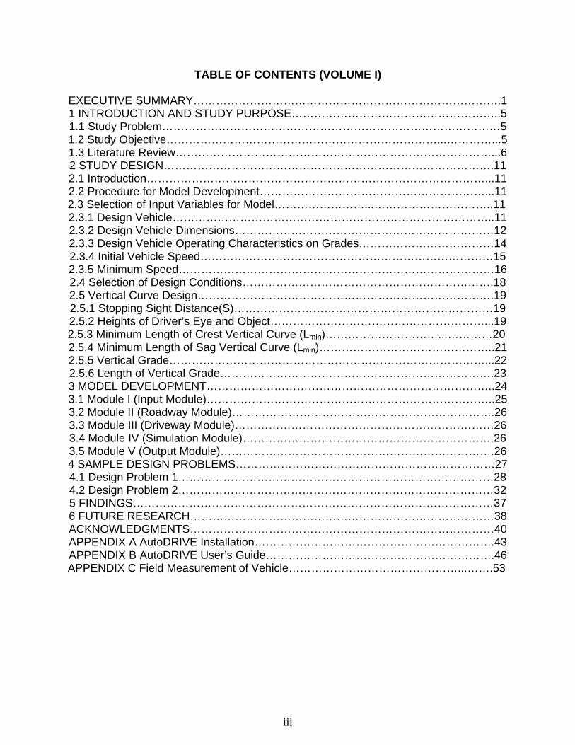
TABLE OF CONTENTS (VOLUME I) EXECUTIVE SUMMARY……………………………………………………………………….1 1 INTRODUCTION AND STUDY PURPOSE………………………………………………..5 1.1 Study Problem………………………………………………………………………………5 1.2 Study Objective………………………………………………………………...…………...5 1.3 Literature Review…………………………………………………………………………...6 2 STUDY DESIGN…………………………………………………………………………….11 2.1 Introduction………………………………………………………………………………...11 2.2 Procedure for Model Development……………………………………………………...11 2.3 Selection of Input Variables for Model……………………...…………………………..11 2.3.1 Design Vehicle…………………………………………………………………………..11 2.3.2 Design Vehicle Dimensions……………………………………………………………12 2.3.3 Design Vehicle Operating Characteristics on Grades………………………………14 2.3.4 Initial Vehicle Speed……………………………………………………………………15 2.3.5 Minimum Speed…………………………………………………………………………16 2.4 Selection of Design Conditions………………………………………………………….18 2.5 Vertical Curve Design…………………………………………………………………….19 2.5.1 Stopping Sight Distance(S)……………………………………………………………19 2.5.2 Heights of Driver’s Eye and Object…………………………………………………...19 2.5.3 Minimum Length of Crest Vertical Curve (Lmin)…………………………...…………20 2.5.4 Minimum Length of Sag Vertical Curve (Lmin)………………………………………..21 2.5.5 Vertical Grade…………………………………………………………………………...22 2.5.6 Length of Vertical Grade……………………………………………………………….23 3 MODEL DEVELOPMENT…………………………………………………………………..24 3.1 Module I (Input Module)…………………………………………………………………..25 3.2 Module II (Roadway Module)…………………………………………………………….26 3.3 Module III (Driveway Module)……………………………………………………………26 3.4 Module IV (Simulation Module)………………………………………………………….26 3.5 Module V (Output Module)……………………………………………………………….26 4 SAMPLE DESIGN PROBLEMS……………………………………………………………27 4.1 Design Problem 1…………………………………………………………………………28 4.2 Design Problem 2…………………………………………………………………………32 5 FINDINGS……………………………………………………………………………………37 6 FUTURE RESEARCH………………………………………………………………………38 ACKNOWLEDGMENTS………………………………………………………………………40 APPENDIX A AutoDRIVE Installation……………………………………………………….43 APPENDIX B AutoDRIVE User’s Guide…………………………………………………….46 APPENDIX C Field Measurement of Vehicle………………………………………...…….53

iv
TABLE OF CONTENTS (VOLUME II)
EXECUTIVE SUMMARY………………………………………………………………………1 1 INTRODUCTION AND STUDY PURPOSE……………………………………………..5 1.1 Introduction………………………………………………………………………………….5 1.2 Study Scope and Objective……………………………………………………………….5 1.3 Study Approach…………………………………………………………………………….6 2 DEVELOPMENT OF SIGHT DISTANCE STANDARDS………………………………7 2.1 CASE-1: Design Vehicle (P) Turning Left From the Driveway into the Main Road
From A Stopped Position………………………………………………………………….8 2.2 CASE-2: Design Vehicle (P) Turning Right From the Driveway into the Main Road
From A Stopped Position…………………………………………………………………15 3 EFFECTS OF DRIVEWAY GRADE ON SIGHT DISTANCE………………………...18 4 DESIGN PROCEDURE…………………………………………………………………..19 5 CONCLUSION AND RECOMMENDATIONS………………………………………….22 6 FUTURE RESEARCH…………………………………………………………………….23 REFERENCES…………………………………………………………………………………24
v
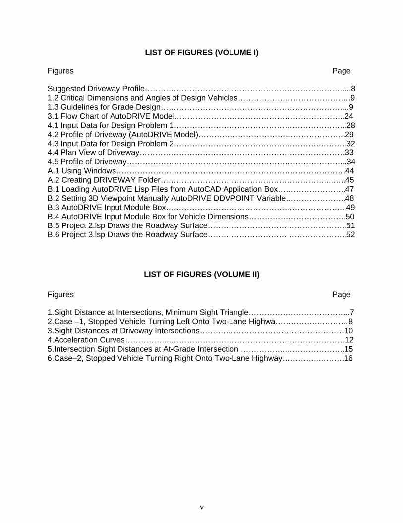
LIST OF FIGURES (VOLUME I) Figures Page Suggested Driveway Profile…………………………………………………………………....8 1.2 Critical Dimensions and Angles of Design Vehicles…………………………………….9 1.3 Guidelines for Grade Design……………………………………………………………...9 3.1 Flow Chart of AutoDRIVE Model………………………………………………………..24 4.1 Input Data for Design Problem 1………………………………………………………...28 4.2 Profile of Driveway (AutoDRIVE Model)………………………………………………..29 4.3 Input Data for Design Problem 2……………………………………………….………..32 4.4 Plan View of Driveway……………………………………………………………………33 4.5 Profile of Driveway………………………………………………………………………...34 A.1 Using Windows……………………………………………………………………………44 A.2 Creating DRIVEWAY Folder………………………………………………………...…..45 B.1 Loading AutoDRIVE Lisp Files from AutoCAD Application Box……………………..47 B.2 Setting 3D Viewpoint Manually AutoDRIVE DDVPOINT Variable…………………..48 B.3 AutoDRIVE Input Module Box…………………………………………………………...49 B.4 AutoDRIVE Input Module Box for Vehicle Dimensions……………………………….50 B.5 Project 2.lsp Draws the Roadway Surface……………………………………………..51 B.6 Project 3.lsp Draws the Roadway Surface……………………………………………..52
LIST OF FIGURES (VOLUME II)
Figures Page 1.Sight Distance at Intersections, Minimum Sight Triangle…………………….…………..7 2.Case –1, Stopped Vehicle Turning Left Onto Two-Lane Highwa…………….…………8 3.Sight Distances at Driveway Intersections……….………………………………………10 4.Acceleration Curves……………...…………………………………………………………12 5.Intersection Sight Distances at At-Grade Intersection ……………..…………………..15 6.Case–2, Stopped Vehicle Turning Right Onto Two-Lane Highway…………..……….16
vi
LIST OF TABLES (VOLUME I)
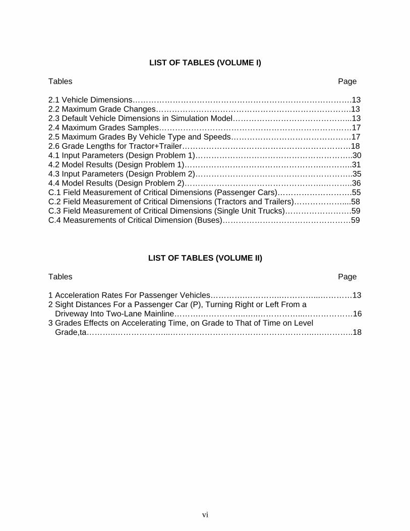
Tables Page 2.1 Vehicle Dimensions……………………………………………………………………….13 2.2 Maximum Grade Changes……………………………………………………………….13 2.3 Default Vehicle Dimensions in Simulation Model……………………………………...13 2.4 Maximum Grades Samples………………………………………………………………17 2.5 Maximum Grades By Vehicle Type and Speeds………………………………………17 2.6 Grade Lengths for Tractor+Trailer………………………………………………………18 4.1 Input Parameters (Design Problem 1)…………………………………………………..30 4.2 Model Results (Design Problem 1)…………………………………………….………..31 4.3 Input Parameters (Design Problem 2)…………………………………………………..35 4.4 Model Results (Design Problem 2)…………………………………………….………..36 C.1 Field Measurement of Critical Dimensions (Passenger Cars)……………………….55 C.2 Field Measurement of Critical Dimensions (Tractors and Trailers)………………....58 C.3 Field Measurement of Critical Dimensions (Single Unit Trucks)…………………….59 C.4 Measurements of Critical Dimension (Buses)…………………………………………59
LIST OF TABLES (VOLUME II)
Tables Page 1 Acceleration Rates For Passenger Vehicles………….…………..…………...…………13 2 Sight Distances For a Passenger Car (P), Turning Right or Left From a Driveway Into Two-Lane Mainline……….……………..…..……………...………………16 3 Grades Effects on Accelerating Time, on Grade to That of Time on Level Grade,ta………..………………...……….……………………………………..….………..18

1
EXECUTIVE SUMMARY
Introduction Currently, the New Jersey Department of Transportation’s standards for State highway driveway grades are based on American Association of State Highway and Transportation Officials(AASHTO) guidelines, which are based on engineering judgements rather than research. The design of driveways is of great importance in terms of both safety and capacity of the roadway and the driveway. This study was conducted to reevaluate the AASHTO standards by attempting to extend the permissible grades for driveways.
Objectives The following issues are some of those that the study addresses. • determine the possibility of developing more liberal design standards than those in
current practice, and • develop new driveway grade standards based on data collected throughout the U.S.
and by computer simulation.
Volume I – Design for the Simulation Model The basic approach to the study is the development and application of a computer simulation model to assist an engineer in selecting a driveway profile starting from the outside edge of the main roadway. The AutoCAD simulation model (AutoDRIVE) has five modules: 1. Input Module – allows user to enter input variables 2. Roadway Module – draws roadway based on input variables 3. Driveway Module – draws driveway grades and inserts vertical curves 4. Simulation Module – places the design vehicle on driveway and performs simulation 5. Output Module – computes critical design parameters and displays results. The Input Module prompts the user to enter the following parameters: • Design vehicle, • Entering/initial speed (U) of the design vehicle, • Minimum allowable speed on upgrades, • Physical elements of roadway, • Physical elements of roadway shoulder and driveway, • Lengths of driveway vertical curves In the Roadway Module, the following functions are performed: • Set the drawing limits, • Draw the roadway In the Driveway Module, the following functions are performed:

2
• Draw the driveway surface, • Place the design vehicle on the driveway surfaceIn the Simulation Module, the
following functions are performed: • Move the vehicle, • Check appropriateness of cross-over, departure, and approach angles, • Check for minimum standards, • Check appropriateness of stopping sight distance Simulation Model AutoDRIVE is a 3D CAD based program that simulates the movement of selected design vehicle on the driveway profile. The program was developed using AutoLISP programming language, and it is written in DOS text using a suitable text editor. AutoDRIVE operates in AutoCAD environment and can be run on a personal computer (PC). The step by step instructions for using and installing AutoDRIVE on a PC are given in the manuals in the appendix. Users are allowed to enter design vehicle types, design vehicle dimensions, initial vehicle speed, and minimum speed. Although AASHTO lists several design vehicle types, there are practical limits in measuring clearances on vehicles. A field study was conducted to obtain clearance information. The vehicle operation characteristics on grades are governed by a vehicle speed-loss formula proposed by Thomas Gillespie (18), which follows. DU/dX= 0.465[375(P/W)/U-Gr]g/U where, U = initial vehicle speed, or speed of vehicle entering grade (mph) X = distance (ft) Gr = road grade (percent/100) g = gravitational constant (32.2 ft/sec2) P/W = ratio of drive horsepower to vehicle weight At the end of the program run, the model checks appropriateness of cross-over, departure, and approach angles, minimum standards, (such as minimum speed), and the appropriateness of stopping sight distance by advancing the vehicle. The major outputs of the simulation module include: • Simulated speed at the end of Grade 1 (Km/h) (converted to km/h) • Simulated speed at the end of Grade 2 (Km/h) (converted to km/h) • Maximum allowable approach angle (degrees) • Maximum allowable cross-over angle (degrees) • Maximum allowable departure angle (degrees) • Grade combination approach/departure angle (degrees) • Grade combination cross-over angle (degrees) • Stopping sight distance required (m) • Length of curve between G1 & G2 is OK (Y/N) • Length of curve between shoulder & G1 is OK (Y/N) • Length of curve between G2 & property elev. Grade is OK (Y/N)

3
• Grade 1 is OK (Y/N) • Grade 2 is OK (Y/N) • Length of Grade 1 is OK (Y/N) • Length of Grade 2 is OK (Y/N) Vertical Curve Design This study incorporates symmetrical parabolic vertical curves for the driveways to achieve better safety and comfortable operations on the grades. The design of vertical curves follows the AASHTO standards. Sample Designs Two design examples illustrate how the guidelines, methodologies, and models can be used in designing and evaluating the vertical alignment of driveways.
Volume II – Sight Distance Standards This research effort has been designed to achieve the following objectives:
• Determine and develop the design standards that ensure safe sight distance for vehicles entering a driveway from the main line and for vehicles exiting from the driveway onto the major road, for the most critical conditions.
• Determine the possibility of developing more liberal design standards when the above mentioned situations are complicated by adverse combinations of curvatures and grades. This usually happens with either the main road or the driveway, or when there are lateral obstructions along the main road that can cause severe reduction in the sight distance from the main road to the driveway or vice versa.
The second volume discusses the minimum sight distance design requirements for passenger cars on the mainline and the driveway. Case studies and resulting tables are presented for perpendicular driveway alignments and for a range of driveway vertical grades (not to exceed a crossover grade of 9.4% as noted in Table 2.2 of Volume 1).
Future Research In future studies, the following issues need to be addressed: • Beside perpendicular driveways, the issues related to the combination of horizontal
curves and grades need to be considered, because some driveways do not proceed perpendicular from the edge of the main road to the property.
• In this study the design of vertical curves on grades follows the AASHTO standards, which is suitable only for regular roadways. In future studies, a vertical curve design should be established specifically for driveways.

4
• The cross-over, approach and departure angles of a moving vehicle are significantly different from those of a stopped vehicle. In future studies, moving vehicle suspensions need to be included in the checking stage of the program.
• The current simulation model is an iterative procedure. In future studies, it could be upgraded to an optimization procedure to help engineers and transportation planners in their decision-making regarding driveway design.

5
1. INTRODUCTION AND STUDY PURPOSE
1.1 Study Problem Currently, the New Jersey Department of Transportation (NJDOT) standards for State highway driveway grades are based on American Association of State Highway Officials (AASHTO) guidelines, which were developed in 1959. The AASHTO driveway grade standards are not supported by research and were probably based on the best engineering judgement at the time they were developed. Therefore, there is a need for reevaluation of those standards based on modern traffic and vehicle conditions and sight distance requirements. The design of safe driveways encompasses many elements, namely, spacing, volume, use of property, angle of exit and entry, alignment, grade and superelevation of the highway and grade of the driveway. The importance of considering these elements in the driveway design would be reflected in the safety and capacity of the roadway and the driveway. As will be noted in the literature review there have been several studies, and some statements of practice, providing guidelines for various design factors. The use of the term “guidelines” concedes the potential for situations that are beyond those ordinarily encountered.
There are occasions when an increase, beyond the accepted guidelines, in the positive or negative grade of a driveway, would considerably reduce the cost of providing driveway access to the land parcel. It is further noted that most driveways are short in length and would cause vertical curve problems because of this small length (1). It is because of these situations that the current study was conducted.
1.2 Study Objective The research effort has been designed to:
• determine the possibility of developing more liberal design standards than those in current practice, and
• develop new driveway grade standards based on data collected throughout the U.S. and by computer simulation.
Two distinct and separate approaches to the problem were developed. The first volume of the two volume report details the development and use of a simulation model. The model development includes information on vehicle design, vehicle dimensions, vehicle operating characteristics on grade, and a vehicle’s initial and minimum speeds on grade. The second volume details the design requirements for the minimum sight distance for passenger cars on the mainline and the driveway. Case studies and resulting tables are presented for perpendicular alignments, a crest curve, and three mainline horizontal curves.

6
1.3 Literature Review Several studies have been conducted addressing the design elements for driveways. The following reviewed literature briefly summarizes the most relevant articles. But as can be seen in the review, scant information is available on the development of the recommended grades for driveways. The importance of proper driveway design is highlighted by the accident involvement of vehicles related to the driveways. In an early study (2), researchers simulated driving conditions for run-off-the-road accidents. Using specific embankment and back slopes, they concluded that a) driveway slopes present a roadside hazard, and b) the most cost effective driveway slope design standard is 8:1 (or 12.5%).
In a study of roadways in Texas (3), a significant number of accidents were found to be related to driveways; 10% of the total accidents on the state highway system and 16% of off-system accidents were in this category. The authors did not attempt to isolate the reasons for the accidents, except that they were related to driveways.
In an effort to provide access control guidelines to the Virginia DOT, the University of Virginia developed a methodology for commercial driveway spacing based on safety and level of service (4). But driveway profile was not included as one of the parameters in the model.
New Jersey Institute of Technology (NJIT) conducted a study of the relationship of driveways to accidents in New Jersey (5). It was found that “Approximately 30% of the reported accidents were midblock section accidents, which were primarily caused due to the presence of access points… Midblock section accidents were mainly caused by vehicles entering and exiting midblock access points.”
In 1970, Texas A&M conducted a study for the National Cooperative Highway Research Program (NCHRP) (6) to develop guidelines for access control on major roadways. They state that “Access control ... insures that an arterial ... will continue to have a high traffic movement capability in future years.” The states of Washington and Wisconsin were found to have made the most advances in implementing access controls on a system-wide basis. Although no specific limitations on grade are offered, grade change generalizations are made as follows:
• “... standards ... would be in terms of performance or smoothness, but sufficient data relating driveway profile to smoothness and acceptable vehicle speed are not available...”
• “ Where severe topography requires extreme grade changes, their undesirable effects can be largely offset by connecting the tangents with vertical curves. ... the desired length of curve (should be) ... approximately the wheel base of a passenger vehicle...”

7
• For low volume driveways, the maximum change (without using vertical curves) is 6% for arterial and collector streets, and a maximum change controlled by vertical clearance for local streets.
Another study “evaluated the effects of driveway width, curb return radius, and offset taper approach treatments on the speed and path of drivers entering and leaving driveways ...” (7). However, the studies were conducted on level terrain, without the added benefit of other traffic.
A 1983 study (8) on access control stated that “Driveway profile is a critical element of driveway design. It influences the speed and path of driveway users and therefore affects driveway operation and safety.” General profile guidelines were offered by the authors.
The Institute for Transportation Engineers issued guidelines in 1987 (9) that included suggestions for driveway grades. It is recommended that exceeding the suggested grade changes should be accompanied by vertical curves. The importance of driveway profile design is justified from three aspects, including safety, comfort of vehicle occupants, and potential damage of the underside of vehicles. The report states that “Maximum grades are established by the physical dimensions of vehicles (principally wheelbase) and braking capacities, primarily of trucks. Designs must then be further refined as to: a) curb and shoulder cross-section within the right-of-way, and b) whether a sag or crest curve is required to complete the driveway beyond the right-of-way.” The report suggests maximum grades for three classes of driveways, which are show in Figure 1.1. Suggested maximum grades for residential, and commercial and industrial driveways are 15 percent, and 5 to 8 percent, respectively. Driveway grades are recommended to be limited to 6 percent within 10 feet of the roadway edge. The driveway slope upward from the gutter line is suggested to be at least 10 feet and 40 feet long for residential and commercial driveways, respectively. For abrupt grade changes, vertical curves are recommended to connect tangents.

8
Source: Reference 9
Figure 1.1 Suggested Driveway Profile
Although a 1988 review of driveway regulation practices does not list driveway grade in the general contents of a regulation for design standards, it does suggest that “The design elements of each high-volume driveway ..., and grades should be based on expected volumes by direction of arrival, and by vehicle characteristics” (10).
A 1991 Texas study of guidelines for vertical alignment of driveways lists four general engineering considerations that should be considered in the design:
• human factors for driver ability and driver comfort, • traffic characteristics for volumes, speed, vehicle type and accidents, • physical elements for geometric design, traffic control and intersection
location, and • economic factors for direct and indirect costs.
For engineering design they further list four specific design elements: area type (rural, urban, suburban), driveway classification (residential, public, commercial, industrial), streets and highways (arterials, collectors, local), and design vehicle (length, clearances, wheelbase). The critical dimensions and angles for a design vehicle are shown in Figure 1.2. The authors conclude that if minimum guidelines cannot be followed, as outlined in the Federal Highway Administration (FHWA) publication Access Management for Streets and Highways, and illustrated in Figure 1.3, “adjustments should be made using engineering judgment (11).”

9
Source: Reference 11
Figure 1.2 Critical Dimensions and Angles of Design Vehicle
Source: Reference 11
Figure 1.3 Guidelines for Grade Design

10
The 1992 NCHRP study (12) on access management for activity centers qualifies the guidelines outlined in the FHWA publication. “Driveways vary widely in their design requirements. A driveway leading to a single residence is usually a simple curb cut that is limited in size. Conversely, a driveway leading to a major activity center, a shopping center, or a corporate office park is really an arterial street and must be designed as such.” The initial grade for a driveway is predicated on the existence of a curb. The recommendation for subsequent grades are similar to those suggested above.
One of the most recent publications on the subject of access management was developed by the Transportation Research Board Committee on Access Management (13). It is a comprehensive synopsis of the findings and engineering judgments to date governing spacing practices. But specific guidelines are not suggested for the profiles of driveways.
The FHWA developed an NHI course (14) on access management in 1991. A compelling safety argument for the careful design of driveways is found in section 3.4.1, Vehicles Traveling Slower Than the Average Speed of Traffic Are More Likely to be Involved in a Crash. It was shown that the relative crash rates increased exponentially with speed differential. Section 3.9.2 relates the vertical alignment of driveways to the functional classification of the roadway, recommending 15% as the maximum grade on minor collectors and local roads.
The New Jersey Department of Transportation (NJDOT) State Highway Access Management Code (15) gives guidelines for driveway profile controls under subchapter 16:47-3.8, "Access point control dimensions for streets and driveways." The basis for these guidelines was the 1959 American Association of State Highway and Transportation Officials (AASHTO) standards, which were not substantiated by empirical data.

11
2. STUDY DESIGN
2.1 Introduction The nature of the study requires an explanation of several aspects of both the study design and expected output. The two basic approaches to the study are the determination of the limiting sight distances on the mainline and driveway for passenger cars (volume 2), and the development and application of a computer simulation model to assist an engineer in selecting a driveway profile starting from the outside edge of the main roadway (volume 1). This section of the report will explain the steps and input in the modeling process and provide background details for the procedure. As further background, a limited number of interviews were conducted with State, Federal, and academic professionals to receive their views on the limits to design standards (16). A list of those interviews is in Appendix A.
2.2 Procedure for Model Development The AutoCAD simulation model (AutoDRIVE) has five modules. These modules are listed below based on the type of function each module performs: • Input Module – allows user to enter input variables • Roadway Module – draws roadway based on input variables • Driveway Module – draws driveway grades and inserts vertical curves • Simulation Module – places the design vehicle on driveway and performs simulation • Output Module – computes critical design parameters and displays results
2.3 Selection of Input Variables for Model
2.3.1 Design Vehicle Design vehicles (DV) are selected motor vehicles with dimensions, operating characteristics, and weight used to establish driveway design controls for accommodating vehicles of designated classes. The largest of all the several design vehicles are usually accommodated in the design of highways. For design of driveways, selection of design vehicle will be based on: a) type of driveway (e.g., passenger car for residential driveway, SU/WB-12/WB-18 for commercial or industrial driveway), b) physical dimensions and operating characteristics of the vehicle. The current version of AutoDRIVE model allows selection of design vehicle from the following three general classes (based on AASHTO Green Book):
1. Passenger cars (P) 2. Trucks
• Single-unit truck (SU)

12
• Truck - intermediate semitrailer combination (WB-12) • Truck – large semitrailers combination (WB-15) • Truck – double bottom semitrailer/full trailer combination (WB-18)
3. Bus • Single unit bus (BUS)
2.3.2 Design Vehicle Dimensions
The physical dimensions of a design vehicle (see Figure 1.2) include:
1. Height – Height of vehicle measured from roadway surface to the roof of vehicle, in meters.
2. Length – Overall bumper-to-bumper length of vehicle, in meters. 3. Front Overhang – Length, in meters, from the front edge of vehicle’s front
bumper to the center of its front axle. 4. Rear Overhang – Length, in meters, from center of the vehicle’s rear axle to the
edge of the rear bumper. 5. Wheelbase – Length, in meters, from center of the vehicle’s front axle to center
of its rear axle. 6. Front, Rear, Base Clearances - Vertical height, in meters, between roadway
surface and low point of the front, rear, and base of vehicle, respectively. 7. Approach, Departure, and Cross-Over Angles – Approach and departure angles
are used to determine critical sag grade breaks, and cross-over angles are used to determine critical crest grade breaks (see Figure 1.2).
Although AASHTO lists several design vehicle types, there are practical limits in measuring clearances on vehicles and on the classification of vehicles using driveways. Each of the vehicle types considered in the study are defined by the P/W ratios (see Section 2.3.3.2), and by the following critical dimensions and angles referred to in Figure 1.2. All dimensions in Table 2.1 are shown in meters. The dimensions were taken from field measurements, and are listed in the Appendix C.

13
Table 2.1 Vehicle Dimensions
Design Criteria Vehicle Type PC SU TT Bus Wheelbase 2.32-3.11 3.41-5.55 6.83-
11.59 N/A
Base Clearance 0.18-0.37 0.21-0.58 0.46-0.85 N/A Front Clearance 0.18-0.52 N/A N/A N/A Rear Clearance 0.24-0.46 0.30-0.49 N/A N/A Front Overhang 0.73-1.28 N/A N/A N/A Rear Overhang 0.61-1.43 1.83-2.68 N/A N/A Max. App. Grade Change
18% N/A N/A 8.3%
Max. Dep. Grade Change
16% 16% N/A 7.6%
Max. Crossover Grade 12.5% 12.5% 13% 10% To include the impact of the dynamics of a vehicle’s suspension on the points of vertical intersection of the driveways, the grade change maximum values are reduced by a factor of 0.75 and shown in Table 2.2.
Table 2.2 Maximum Grade Changes Design Criteria Vehicle Type PC SU TT Bus Max. Dep./Appro. Grade Change
12% 12% N/A 7.6%
Max. Crossover Grade 9.4% 9.4% 9.8% 10% The AutoDRIVE simulation model uses the default dimensions as shown in Table 2.1 (based on Table II-1 of the AASHTO Green Book and NJIT field survey). The model allows the user to edit/modify these dimensions.
Table 2.3 Default Vehicle Dimensions in Simulation Model OVERHANG WHEELBASE CLEARANCE Design
Vehicle Height
Length Front Rea
r WB1 WB2 WB
3 Front Rear Base
P 1.3 5.8 0.9 1.5 3.4 0.30 0.30 0.30 SU 4.1 9.1 1.2 1.8 6.1 0.37 0.37 0.37 BUS 4.1 12.1 2.1 2.4 7.6 0.40 0.40 0.40 WB-12 4.1 15.2 1.2 1.8 4.0 8.2 0.40 0.45 0.45 WB-15 4.1 16.7 0.9 0.6 6.1 9.1 0.40 0.45 0.45 WB-18 4.1 19.9 0.6 0.9 3.0 6.1 6.4 0.40 0.45 0.45 Source: Reference 17 Note: Vehicle clearances are based on field measurements by NJIT (see Appendix C)

14
2.3.3 Design Vehicle Operating Characteristics on Grades
2.3.3.1 Vehicle Speed-Loss Formula on Grades The following formula offered by Thomas Gillespie (18) combines the power/weight ratio of vehicles, the initial vehicle speed, and the roadway grade to calculate the speed loss per foot of a vehicle.
DU/dX= 0.465[375(P/W)/U-Gr]g/U where, U = initial vehicle speed, or speed of vehicle entering grade (mph) X = distance (ft) Gr = road grade (percent/100) g = gravitational constant (32.2 ft/sec2) P/W = ratio of drive horsepower to vehicle weight The loss of speed is a necessary calculation for vehicles to ensure that the vehicle’s speed is not reduced below a predetermined (minimum) level. On driveways, the lowest level of speed that a vehicle can reach (minimum speed) can be considerably less than that which is permitted on the main road. A later discussion of the minimum speed offers suggestions on an acceptable level.
To establish the maximum grade of a driveway, there are three inputs that must be determined for the speed-loss equation, the P/W ratio for each class of vehicle, the initial speed of the vehicle, and the maximum allowable speed loss on the grade. The minimum speed of the vehicle on the grade will set a limit for the speed loss on the grade.
2.3.3.2 Power to Weight (P/W) Ratio
The user is not expected to input the P/W ratio to the model. Rather, the user will select the most critical (slowest) design vehicle for which the driveway profile will be designed. The P/W ratio will then be determined using the formulae found in the Thomas Gillespie reference, which offers P/W formulas for various type trucks (18, p.73). Since the data on which the formulae are based is about 15 years old, the 12.5 percentile formulae are increased by a conservative factor (1.1) approximately equivalent to a time-projected change in the W/P ratio (18, p.77 and 17, p.232). Because the P/W ratio of trucks has been increasing over time, this should approximate the less powerful of the trucks (12.5% percentile) on the road today.
Trucks (SU): P/W = 1.1(3.71-.0343U)/1000 Trucks with Trailers(WB-12): P/W = 1.1(2.21-.0122U)/1000 Tractor + trailers(WB-15): P/W = 1.1(3.52-.0339U)/1000 19.8 m (65 ft) Doubles(WB-18): P/W = 1.1(2.96-.0342U)/1000

15
Examples of the P/W ratios for different speeds is as follows: U P/W(trucks) P/W(trucks with trailers) P/W(tractor +) P/W(doubles) mph km/h hp/lb hp/kg hp/lb hp/kg hp/lb hp/kg hp/lb hp/kg 10 16.09 .00370 .00816 .00230 .00507 .00350 .00772 .00262 .00578 25 40.23 .00314 .00692 .00210 .00463 .00294 .00648 .00232 .00512 Translating the above P/W ratios to W/P ratios and comparing them to the AASHTO and ITE references, yields the following ranges: AASHTO/ITE Modified Gillespie Lb/hp kg/hp Lb/hp kg/hp 250-300 113.4-136.1 270-470 122.4-213.2 Passenger cars have less power but also much less weight. Examples of the least and most powerful of the passenger cars on the road were taken from a distribution of auto P/W ratios, as found in Edmunds (19) and shown in the Appendix, and are as follows: P W P/W hp lb kg hp/lb hp/kg 105 2400 1088.4 .0438 0.0966 275 4000 1814.1 .0688 0.1517 A comparison of the P/W ratios of the passenger cars with the trucks, reveals the expected, that passenger cars have more acceleration power on grades. Hence, there is the opportunity to design much steeper grades for passenger cars than for trucks, keeping in mind the stopping requirements of steep negative grades.
2.3.4 Initial Vehicle Speed The initial speed is the speed at which the design vehicle enters the grade. With higher initial speeds, longer sustained positive driveway grades can be installed before the speed of the vehicle may be reduced to unacceptable levels (see the discussion below on minimum speeds).
The initial vehicle speed of a vehicle exiting the mainline is primarily a function of the design of the intersection of the main road and the driveway and the speed limit on the main road. The design engineer is in the best position to select an initial vehicle speed, but a minimum value of 15 Km/hr is chosen as the default by the model, as reasoned below.
Those access designs (levels) that present the most difficult situations from the point of view of inducing low initial truck speeds are unsignalized access levels 4 and 5 and access level 6 (reference 15). A large semitrailer truck, from a stopped position, making a left turn from the main road into a driveway requires at least 18m (60 ft) to accelerate to a speed of 15 km/h (10 mph) (17, p.703-5). For the semitrailer truck to accelerate to a speed of 20 km/h (13 mph), it would require 31m (100 ft). To attain these speeds the driveway

16
profile must not introduce a positive grade that will cause the vehicle to decelerate. Under this mainline/driveway design condition, the attainment of higher initial truck speeds requires greater distances before the start of a positive grade.
At a distance of 18m from the stopped position, a left turning semitrailer is still partially blocking the left lane of the opposing traffic. If a steep positive grade is introduced at this point, the semitrailer will start to decelerate, thereby blocking the opposing lane for a slightly longer period of time. To reduce the total length of the driveway though, the model introduces a positive grade at a variable point 15m (50 ft) from the edge of the travel way. Negative grades can be introduced sooner; the only factor that the negative grade must accommodate is the possible introduction of a crest curve and its clearance from the edge of travel way or shoulder.
The importance of the initial speed of a truck is highlighted by its influence with both the P/W ratio and speed loss.
2.3.5 Minimum Speed The minimum speed is defined as the slowest speed that is acceptable on a driveway grade. The minimum speed is also important in determining the critical length of a grade. The difference between the initial speed and the minimum speed reflects the maximum speed loss on a grade, which determines the maximum length of grade (critical length) a design vehicle can climb before its speed decelerates below the minimum speed. The design engineer has the option to input the minimum speed, which is obviously less than or equal to the initial speed. Otherwise, a default value will be selected, as determined in the following text. AASHTO (17, p.242) recommends the installation of truck climbing lanes on roads when volume and speed reductions exceed certain limits. The criterion is based on safety and economic considerations. Both are also important considerations for driveways. But driveways must provide a length and grade that prevents a design vehicle decelerating below a minimum acceptable speed, rather than allowing the vehicle to exceed a predetermined speed reduction. Providing additional lanes for a driveway is not considered essential to allow vehicles to bypass slower moving vehicles, unless the driveway volume conditions warrant the lane. As the bracketed term of the vehicle speed-loss formula approaches 0 (section 2.3.3.1), it will yield the maximum grade for which a particular P/W vehicle can maintain its initial speed.
Gmax < 100*375(P/W)/U
Examples of the maximum grades (Gmax) where individual P/W design vehicles can maintain their initial speed (U) are as follows:

17
Table 2.4 Maximum Grades Samples Maximum G U P/W Vehicle Type mph km/h hp/lb hp/km 9 10 16.09 0.00230 0.00507 trucks with trailers 14 10 16.09 0.00370 0.00816 Trucks 6 15 24.14 0.00223 0.00492 trucks with trailers 9 15 24.14 0.00352 0.00776 Trucks 4 20 32.18 0.00216 0.00477 trucks with trailers 6 20 32.18 0.00333 0.00734 Trucks 3 25 40.23 0.00210 0.00463 trucks with trailers 5 25 40.23 0.00314 0.00692 Trucks As expected, the lower the initial speed of the vehicle, the higher the P/W ratio, the steeper is the grade on which the vehicle’s speed can be maintained. Under different sustained speeds, the maximum grades for design vehicles would be as follows. But most driveways may not be designed for the higher speeds.
Table 2.5 Maximum Grades By Vehicle Type and Speeds
Design Vehicle Speed
10 mph 15 mph 20 mph 25 mph Passenger Car >14% >9% >6% >5% Truck(SU)(*bus the same as truck) 14% 9% 6% 5% Tractor-trailer (WB-15) 13% 8% 6% 4% Bus 14% 9% 6% 5% If the initial speed is as low as 15 km/h, a minimum speed of 7.5km/h (approximately 5 mph) may be permitted. This is not a speed that will be experienced by many vehicles; in fact, it will only reflect the oldest and heaviest vehicles on the road. These vehicles represent the 12.5 percentile of the population. Since a very conservative approach has been taken with the use of the P/W ratio, the representation of these vehicles in the population is very small. Using the vehicle speed-loss formula, examples of the critical length of grade for trucks+trailers are as follows (the length of grade at which the vehicle will stop on the grade is also shown). Although most driveways are less than 100’, it is important that limiting lengths are shown for those cases where needed.

18
Table 2.6 Grade Lengths for Tractor + Trailers
Gmax U P/W Critical Length of Grade Min. Speed of 0 mph Min. Speed of 5 mph mph km/h hp/lb hp/kg ft m ft m
14% 10 16.09 0.0035 0.00772 760 230 380 115 15% 10 16.09 0.0035 0.00772 360 110 180 55 16% 10 16.09 0.0035 0.00772 230 70 115 35 14% 25 40.23 0.0029 0.00639 170 52 85 26 15% 25 40.23 0.0029 0.00639 160 49 80 25 16% 25 40.23 0.0029 0.00639 140 43 70 22 The discussion of the minimum vehicle speed was not expected to result in a definitive value, but rather suggest a value that can be used in lower level access cases. For situations other than those specified in the text (access levels 4 and 5 and access level 6 from reference 15), the minimum vehicle speed for a driveway may be much higher than 7.5 km/h (the suggested default value). The design engineer may have reason to set a much higher value (consistent with the initial speed), such as to avoid queues backing onto the mainline. The model uses a default minimum speed of 7.5 Km/hour.
2.4 Selection of Design Conditions
When using the model, the design engineer can specify conditions in its application. Others could exist, but these are thought to represent the most common. The designer has the option of selecting any or all of these conditions. Limitations on the proposed grades are set which will determine the design conditions that are acceptable.
a) The right-of-way that exists or is to be acquired may be a limiting factor for the
distance beyond the edge of shoulder that the driveway can extend. Applying this grade may involve the use of a vertical curve, which would also be within the right-of-way.
b) If the driveway profile cannot attain the grade of the property within the right-of-way, the maximum grade may be suggested. This would necessarily extend beyond the right-of-way.
c) There may be situations where conditions require the attainment of the grade of
the property at a specific point. The option will be offered to the design engineer to select any distance desired.
The introduction in the model of vehicle operating characteristics on grades, vehicle speed loss, initial and sustained vehicle speeds, and the design of vertical curves, suggests a minimum length of grade for the driveway, before consideration is given to using the model. There is no hard and fast minimum to the length of grade to use for the model, but because the vertical curves extend the driveway at two points of vertical intersection, a minimum driveway length of 50’ would seem reasonable for use with the model. Therefore, the modeling approach outlined in Volume I-subtitled Design for the Model would only be considered for driveways greater than 50’ in length.

19
For driveways shorter than 50’, the designer must first select a grade for the design vehicle (Table 2.5), and check it against the maximum approach/departure grade change, or the crossover grade change (Table 2.2). The designer must then refer to the tables in Volume II-subtitled Design for Sight Distance Considerations to check the limitations for sight distance. The use of the sight distance approach can actually be used for any length driveway.
2.5 Vertical Curve Design ASSHTO’s recommendation for a vertical curve suggests a “...design that is safe (ample sight distance for the design speed), comfortable in operation (ample clearance for the undercarriage of the vehicle and comfortable for the motorist), pleasing in appearance (a long curve has a more pleasing appearance), and adequate for drainage.” The AutoDRIVE model incorporates only symmetrical parabolic vertical curves for driveways.
2.5.1 Stopping Sight Distance (S) Stopping sight distance is a crucial control for design of vertical curves. S = 0.278 U t + U2 / [254 (f + G)] Where, S = stopping sight distance, in meters U = initial/entering speed, in Km/hr t = brake-reaction time = 2.5 seconds (recommended by AASHTO) f = coefficient of friction between tires and roadway (wet pavement) G = longitudinal grade (e.g., if grade = -6%, G for the above formula will be –0.06) The model uses the following ‘f’ values (based on AASTO Green Book): U = 15 Km/hr, f = 0.43; U = 20 Km/hr, f = 0.42; U = 25 Km/hr, f = 0.41; U = 30 Km/hr, f = 0.40; U = 35 Km/hr, f = 0.39; U = 40 Km/hr, f = 0.38; U = 45 Km/hr, f = 0.37; U = 50 Km/hr, f = 0.35; U = 55 Km/hr, f = 0.34; U = 60 Km/hr, f = 0.33; U = 65 Km/hr, f = 0.32; U = 70 Km/hr, f = 0.31
2.5.2 Heights of Driver’s Eye and Object Height of Driver’s Eye (h1)
For passenger cars, h1 = 1.07 m For trucks or buses, h1 = 2.4 m

20
Height of Object (h2) For all design vehicles, h2 = 0.15 m
2.5.3 Minimum Length of Crest Vertical Curve (Lmin)
The general condition for a crest vertical curve is grade 1 > grade 2 (or G1 > G2). The obstruction that limits the driver’s sight distance is the road surface at some point on a crest vertical curve. The major control for safe operation on a crest vertical curve is the provision of ample sight distance for the vehicle entering speed. The other control is the crest curve length in relation to wheelbase length of the design vehicle to avoid cross-over angle hazard. The AutoDRIVE model compares the user’s entered length of vertical curve with the minimum length (Lmin) required. That is, if Lprovided > Lmin, the curve design length is okay. Otherwise, the model will warn the user that the length of curve is not appropriate. For driveway design, Lmin is the greater of the following two: Condition 1.
when S < L, Lmin = A S2 /{100 [ (2 h1)1/2 + (2 h2)1/2 ] 2 } when S > L, Lmin = 2 S – {200 [ ( h1)1/2 + ( h2)1/2 ] 2 } / A
where,
Lmin = length of vertical curve, in meters S = stopping sight distance, in meters
A = |G2% – G1%| (e.g., if G2 = -4% and G1% = +3%, A = | -4 – (+3) | = 7) h1 = height of driver’s eye, in meters h2 = height of object, in meters
Condition 2.
Lmin = wheelbase of the design vehicle, in meters Maximum Cross-Over Angle
If Lmin is based on condition 2 above, the model computes the cross-over angle as follows: Maximum cross-over angle = Tan-1 [base clearance / (0.5 wheelbase)] In the above formula, before using the input base clearance value it is first reduced by 25% to take into account the dynamic oscillation of a loaded vehicle along the vertical axis while traversing a curve at slow speed. That is, the model uses the following modified relation:

21
Maximum cross-over angle = Tan-1 [0.75 base clearance / (0.5 wheelbase)] Note that in the above relation, for WB-12 and WB-15, wheelbase = maximum (WB1 and WB2) and for WB-18, wheelbase = maximum (WB1, BW2, and BW3). Cross-Over Angle Due to Grade Combination
The cross-over angle due to combination of grades provided is computed by the model as follows:
Available cross-over angle = Tan -1 {(|G2| - |G1| - [A Lprovided)/800]) / 100}
The model performs the following check:
If available cross-over angle < maximum cross-over angle, design is OK. Otherwise, a warning is echoed to the user regarding the inappropriate design.
2.5.4 Minimum Length of Sag Vertical Curve (Lmin) The general condition for a sag vertical curve is grade 1 < grade 2 (or G1 < G2). The AutoDRIVE model uses the headlight sight distance criterion to compute the minimum required curve length. When a vehicle traverses a sag vertical curve at night, the portion of highway lighted ahead is dependent on the position of the headlights and the direction of light beam. The AASHTO Green Book recommends use of a headlight height of 0.6 meter and a 1 degree upward divergence of the light beam from the longitudinal axis of the vehicle. However, this is valid for open highways only. For driveways, it is assumed that the driver can use high beam light at night to see driveway alignment ahead. The study team field observed (for a few vehicles) the upward divergence angle of high beam light. The angle was observed to be approximately 15 degrees. The AutoDRIVE model uses a conservative value of 11.3 degrees for computing length of a sag vertical curve. The modified equations are: Condition 1.
when S < L, Lmin = A S2 / (120 + 3.5 S) when S > L, Lmin = 2 S – [(120 + 3.5 S) / A]
where,
Lmin = length of vertical curve, in meters S = stopping sight distance, in meters
A = |G2% – G1%| (e.g., if G2 = -4% and G1% = +3%, A = | -4 – (+3) | = 7) Condition 2.
Lmin = wheelbase of the design vehicle, in meters

22
Maximum Approach and Departure Angles
If Lmin is based on condition 2 above, the model computes the approach and departure angles as follows: Maximum approach angle = Tan-1 [front clearance / (front overhang)]
Maximum departure angle = Tan-1 [rear clearance / (rear overhang)] In the above formulae, before using the input front and rear clearance values, they are first reduced by 25% to take into account the dynamic oscillation of a loaded vehicle along the vertical axis while traversing a curve at slow speed. That is, the model uses the following modified relations:
Maximum approach angle = Tan-1 [0.75 front clearance / (front overhang)] Maximum departure angle = Tan-1 [0.75 rear clearance / (rear overhang)]
Approach and Departure Angles Due to Grade Combination
The approach/departure angle due to combination of grades provided is computed by the model as follows:
Available approach/departure angle = Tan-1 {[Gcritical - (A Lprovided)/800] / 100}
The model performs the following check:
If available approach/departure angle < maximum approach/departure angle, design is OK. Otherwise, a warning is echoed to the user regarding the inappropriate design.
2.5.5 Vertical Grade In order to determine appropriateness of the input vertical grades, the model performs the following checks:
1. Simulated speed > minimum speed (default minimum speed = 7.5 km/hr) AND
2. In case of crest curve, maximum allowable cross-over angle > available cross-over angle In case of sag curve, maximum allowable approach/departure angle > available approach/ departure angle.
If the above conditions are met then the vertical grade selected is appropriate, otherwise the model displays a warning regarding inappropriateness of the grade.

23
2.5.6 Length of Vertical Grade For length of vertical grade, the model performs the following checks:
1. Length of vertical grade > length of design vehicle 2. Simulated speed at the end of grade > minimum speed (default min. speed =
7.5 km/hr)
IF THE ABOVE CONDITIONS ARE MET THEN THE LENGTH OF VERTICAL GRADE IS APPROPRIATE, OTHERWISE THE MODEL DISPLAYS A WARNING REGARDING INAPPROPRIATENESS OF THE GRADE LENGTH.

24
3. MODEL DEVELOPMENT AutoDRIVE is a 3D CAD based program that simulates movement of a selected design vehicle on a driveway profile. The program was developed using AutoLISP programming language, and it is written in DOS text (ASCII format) using a suitable text editor. AutoDRIVE operates in AutoCAD environment, and includes the following modules: 1. Input Module – allows user to enter input variables 2. Roadway Module – draws roadway based on input variables 3. Driveway Module – draws driveway grades and inserts vertical curves 4. Simulation Module – places the design vehicle on driveway and performs simulation 5. Output Module – computes critical design parameters and displays results A generic flow chart of the model is presented in Figure 3.1. Module I Get User’s Input Module II Draw Roadway Module III Draw Driveway Module IV Perform Simulation Module V Compute and Print Results
Figure 3.1 Flow Chart of AutoDRIVE Model

25
3.1 Module I (Input Module) This module prompts the user to enter the following input parameters:
• Design vehicle. Select the design vehicle from a pop-down menu. A list of design vehicles with their default dimensions (height, length, wheelbase, front overhang, rear overhang, front clearance, base clearance, rear clearance) is provided based on Table II-1 of AASHTO Green Book (17). For example, the user can select P-CAR for passenger car; SU-BUS for single unit bus; SU-TRUCK for single unit truck; and WB-12, WB-15, or WB-18 for truck trailer combinations. The module allows the user to change the dimensions, if desired.
• Entering/initial speed (U) of the design vehicle. The module shows U = 15
Km/hour as the default value. The user can select any initial speed from 15 Km/hr. to 70 Km/hr. with an increment of 5 Km/hr.
• Minimum allowable speed on upgrades of 10 Km/hr. is used as default value.
The user can enter any other desired minimum allowable speed ranging from 7.5 km/hr – 25 km/hr. The model allows to select from the following options:
Minimum speed on upgrade = 7.5, 8, 9, 10, 11, 12, 13, 14, 15, 18, 20, 22, and 25
• Physical elements of roadway. The user can modify default values of:
i) Elevation of the outside edge of pavement (m) ii) Total number of roadway lanes in both directions iii) Width of each roadway lane (m) iv) Roadway normal crown cross-slope.
• Physical elements of roadway shoulder and driveway. The user can modify
default values of: i) Driveway vertical grade 1 (G1 in %) ii) Driveway vertical grade 2 (G2 in %) iii) Length of driveway grade 1 (m) iv) Length of driveway grade 2 (m) v) Roadway shoulder cross-slope vi) Roadway shoulder width (m)
• Lengths of driveway vertical curves. The user can modify default values of:
i) Curve length between shoulder and grade 1 (m) ii) Curve length between grade 1 and grade 2 (m) iii) Curve length between grade 2 and property line grade (m)

26
3.2 Module II (Roadway Module) This module draws the roadway based on user’s input information. These functions are performed in the following sequence: • Set the drawing limits. Based on the input values, this module first defines the
drawing limits, and then changes the zoom to drawing limits. • Draw the roadway. Based on the input information, draws the roadway in 3D.
3.3 Module III (Driveway Module) This module draws the driveway based on user’s input information. These functions are performed in the following sequence: • Draw the driveway surface. Based on the input values of G1, G2, lengths of
grade1 and grade 2, length of vertical curve, and elevation of the start point, the module draws a 3D driveway surface.
• Place the design vehicle on the driveway surface. The module creates a block of the design vehicle and places it on the driveway by making the vehicle tires tangent to the driveway surface.
3.4 Module IV (Simulation Module)
This module performs the following functions: • Move the Vehicle. Simulates the movement of the vehicle on the driveway profile.
The user can view the simulation in a plan or profile viewpoint. Each time, the vehicle is moved by 1 meter from its previous position. At every new location, vehicle tires remain tangent to the surface.
• Check appropriateness of cross-over, departure, and approach angles. • Check for Minimum Standards. If the input values don’t meet the minimum
standards, warn the user and show the minimum design values. This check is performed at the end of a program run.
• Check Appropriateness of Stopping Sight Distance. Advance the vehicle frame by frame to check the appropriateness of the available sight distance.
3.5 Module V (Output Module)
This module reports results of each simulation run.
27
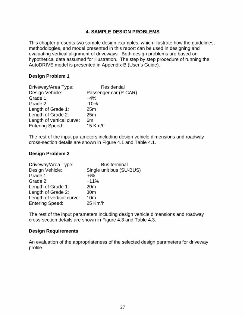
4. SAMPLE DESIGN PROBLEMS This chapter presents two sample design examples, which illustrate how the guidelines, methodologies, and model presented in this report can be used in designing and evaluating vertical alignment of driveways. Both design problems are based on hypothetical data assumed for illustration. The step by step procedure of running the AutoDRIVE model is presented in Appendix B (User’s Guide). Design Problem 1 Driveway/Area Type: Residential Design Vehicle: Passenger car (P-CAR) Grade 1: +4% Grade 2: -10% Length of Grade 1: 25m Length of Grade 2: 25m Length of vertical curve: 6m Entering Speed: 15 Km/h The rest of the input parameters including design vehicle dimensions and roadway cross-section details are shown in Figure 4.1 and Table 4.1. Design Problem 2 Driveway/Area Type: Bus terminal Design Vehicle: Single unit bus (SU-BUS) Grade 1: -6% Grade 2: +11% Length of Grade 1: 20m Length of Grade 2: 30m Length of vertical curve: 10m Entering Speed: 25 Km/h The rest of the input parameters including design vehicle dimensions and roadway cross-section details are shown in Figure 4.3 and Table 4.3. Design Requirements An evaluation of the appropriateness of the selected design parameters for driveway profile.

28
4.1 Design Problem 1
Figure 4.1 Input Data for Design Problem 1

29
Driveway Vertical Curve
Property Elevation Grade = 0% Design Vehicle
Figure 4.2 Profile of Driveway (AutoDRIVE Model) Simulation Results (Design Problem 1) The AutoDRIVE model, after performing design vehicle movement animation, computes all critical design parameters based on criteria established in Chapter 2. The model gives echo of input parameters and simulation output results, which are presented in Tables 4.3 and 4.4, respectively.

30
Table 4.1 Input Parameters (Design Problem 1)
Echo of Input Variables
Input Parameter
Description Input
1 Design Vehicle (DV) * P-CAR
2 DV entering speed (Km/h) 15
3 Driveway Grade 1 (G1%) 4
4 Driveway Grade 2 (G2%) -10
5 Length of Grade 1 (m) 25
6 Length of Grade 2 (m) 25
7 Length of curve between G1 & G2 (m) 6
8 Elevation of outside pavement edge (m) 100
9 Number of roadway lanes in both directions 2
10 Road lane width (m) 3.6
11 Roadway cross-slope (NC%) 2
12 Roadway shoulder width (m) 2
13 Roadway shoulder cross-slope (S%) 4
14 Length of curve between shoulder & G1 (m) 4
15 Length of curve between G2 and property grade (m) 6
16 Minimum allowable speed on upgrades (Km/h) 7.5
*P-CAR, SU-BUS, SU-TRUCK, WB-12, WB-15, WB-18
Design Vehicle (P-CAR) Dimensions
Length FO RO WB1 WB2 WB3 FC BC RC
5.80 0.90 1.50 3.40 0.00 0.00 0.30 0.30 0.30
FO = Front Overhang, RO = Rear Overhang, WB = Wheelbase, FC = Front Clearance, BC = Base Clearance, RC = Rear Clearance

31
Table 4.2 Model Results (Design Problem 1) Simulation Output
Description Output
1 Simulated speed at the end of Grade 1 (Km/h) 15.00
2 Simulated speed at the end of Grade 2 (Km/h) 15.00
3 Maximum allowable approach angle (degrees) Crest Curve
4 Maximum allowable cross-over angle (degrees) 8.53
5 Maximum allowable departure angle (degrees) Crest Curve
6 Grade combination approach/departure angle (degrees) Crest Curve
7 Grade combination cross-over angle (degrees) 7.91
8 Stopping sight distance required (m) 12.31
9 Length of curve between G1 & G2 is OK (Y/N) Y
10 Length of curve between shoulder & G1 is OK (Y/N) Y
11 Length of curve between G2 & property elev. Grade is OK (Y/N) Y
12 Grade 1 is OK (Y/N) Y
13 Grade 2 is OK (Y/N) Y
14 Length of Grade 1 is OK (Y/N) Y
15 Length of Grade 2 is OK (Y/N) Y
The above results indicate that the design parameters selected for the driveway profile are appropriate and meet all the established designed standards. The designer can perform another test run by selecting more liberal design parameters.

32
4.2 Design Problem 2
Figure 4.3 Input Data for Design Problem 2

33
Figure 4.4 Plan View of Driveway

34
Figure 4.5 Profile of Driveway
Simulation Results (Design Problem 2) The AutoDRIVE model, after performing design vehicle movement animation, computes all critical design parameters based on criteria established in Chapter 2. The model gives echo of input parameters and simulation output results, which are presented in Tables 4.3 and 4.4, respectively.

35
Table 4.3 Input Parameters (Design Problem 2)
Echo of Input Variables
Input Parameter
Description Input
1 Design Vehicle (DV) * SU-BUS
2 DV entering speed (Km/h) 25
3 Driveway Grade 1 (G1%) -6
4 Driveway Grade 2 (G2%) 11
5 Length of Grade 1 (m) 20
6 Length of Grade 2 (m) 30
7 Length of curve between G1 & G2 (m) 10
8 Elevation of outside pavement edge (m) 100
9 Number of roadway lanes in both directions 2
10 Road lane width (m) 3.6
11 Roadway cross-slope (NC%) 2
12 Roadway shoulder width (m) 2
13 Roadway shoulder cross-slope (S%) 4
14 Length of curve between shoulder & G1 (m) 4
15 Length of curve between G2 and property grade (m) 6
16 Minimum allowable speed on upgrades (Km/h) 7.5
Design Vehicle Dimensions
Length FO RO WB1 WB2 WB3 FC BC RC
12.10 2.10 2.40 7.60 0.00 0.00 0.37 0.37 0.37

36
Table 4.4 Model Results (Design Problem 2) Simulation Output
Description Output
1 Simulated speed at the end of Grade 1 (Km/h) 34.80
2 Simulated speed at the end of Grade 2 (Km/h) 31.20
3 Maximum allowable approach angle (degrees) 7.53
4 Maximum allowable cross-over angle (degrees) Sag Curve
5 Maximum allowable departure angle (degrees) 6.60
6 Grade combination approach/departure angle (degrees) 6.16
7 Grade combination cross-over angle (degrees) Sag Curve
8 Stopping sight distance required (m) 24.41
9 Length of curve between G1 & G2 is OK (Y/N) Y
10 Length of curve between shoulder & G1 is OK (Y/N) Y
11 Length of curve between G2 & property elev. grade is OK (Y/N) Y
12 Grade 1 is OK (Y/N) Y
13 Grade 2 is OK (Y/N) Y
14 Length of Grade 1 is OK (Y/N) Y
15 Length of Grade 2 is OK (Y/N) Y
The above results indicate that the design parameters selected for the driveway profile are appropriate and meet all the established designed standards. The designer can perform another test run by selecting more liberal design parameters.

37
5 FINDINGS Procedures have been developed to determine the permissible grades on driveways using a simulation model (Vol. I). Within the model, the grades are dependent on the type of vehicle, length of grade, and the speed of the vehicle entering the grade. The conditions of design for each situation will determine the allowable grades to be used for the driveway, which may exceed the suggested guidelines from the ITE publication(9). The more liberal use of design standards can apply to the lower speeds of vehicles that exist on driveways. Lower grades can permit grades to meet at points of intersection, rather than providing vertical curves. The limitation to the intersecting grades is based on the approach/departure and crossover angles of the design vehicle. If steeper intersecting grades are required, the design of a vertical curve is provided.

38
6. FUTURE RESEARCH The study of driveway design is a complicated procedure that needs careful consideration of the driveway geometric characteristics, vehicle operation characteristics, and other relevant issues such as the combination of curves in the grade design procedure. The use of computer simulation techniques in the study of grade design provides an important approach to similar studies in the future. Through the accumulation of simulation experience, computers can be better used in future studies of driveway designs. The following issues are suggested for future studies: In addition to a driveway perpendicular to the roadway, other more complicated driveway geometry needs to be included. The following cases are suggested to be addressed specifically: • Use a driveway profile that will reach the grade of the property within the existing
right-of-way (ROW). • Use a driveway profile that will reach the grade of the property using maximum
possible grade. • Use a driveway profile that will reach the grade of the property at a selected distance
outside the ROW. The issues related to the combination of horizontal curves and grades need to be considered, because some driveways do not proceed perpendicular from the edge of the main road to the property. Vertical curve design on grades is important because, they provide ample sight distance, clearance for the undercarriage of the vehicle and comfortable operating conditions for the motorists, as well as pleasing appearance of driveways. However, the combination of vertical curves in the driveway design procedure is a difficult issue that requires study and large-scale data collection and calibrations nationwide. In this study the design of vertical curves on grades follows the AASHTO standards, which is suitable only for roadways. In future studies, vertical curve standards need to be established specifically for driveways. When a vehicle is moving on a driveway, the suspension of the vehicle varies with both the geometric characteristics of the driveway and the speed of vehicle. The change of suspensions of a moving vehicle leads to the change of cross-over, approach and departure angles, which are critical in the design of vertical grades. The cross-over, approach and departure angles of a moving vehicle, is significantly different from those of a stopped vehicle. In this study, a fixed scale factor is used to adjust the clearance of a moving vehicle. In future studies, moving vehicle suspensions need to be more carefully studied so that the adjustment of the clearance is more accurate. The formulas of power to weight ratio do not include the formula for buses. Although, there is the opportunity to design much steeper grades for passenger cars than for trucks, a P/W ratio formula for buses needs to be developed in future studies.

39
The current simulation model is an iterative procedure. Although transportation engineers and planners can run the simulation model iteratively to come up with the best driveway design, it would be more convenient to have a model that is able to assist them automatically to choose a design by revising the current iterative model to a optimization model. This work is left to the future study.

40
ACKNOWLEDGMENTS This study has been made possible by the support of New Jersey Department of Transportation (NJDOT), NJIT and the National Center for Transportation and Industrial Productivity. The authors would like to extend our thanks to Mr. Arthur Eisdorfer and Mr.Robert Sasor (NJDOT) who initiated and monitored this project. The authors are also indebted to the Office of Major Access Permits (NJDOT) for their comments on the reports.

41
REFERENCES 1. Conversation with Art Eisdorfer, Manager NJDOT Bureau of Civil Engineering,
December 14, 1998, and April 25, 2000. 2. “Cost Effectiveness of Driveway Slope Improvements,” In Transportation Research
Report 685, TRB, National Research Council, Washington, D.C., 1978. 3. “Evaluation of Driveway Related Accidents in Texas,” In Transportation Research
Report 819, TRB, National Research Council, Washington, D.C., 1981. 4. Nicholas J. Garber and Timothy E. White. Guidelines for Commercial Driveway
Spacing on Urban and Suburban Arterial Roads. Department of Civil Engineering, University of Virginia, May 1995.
5. Kyriacos Mouskos, et. al. Impact of Access Driveways on Accident Rates on New
Jersey Highways (Draft). NJIT, June 1998. 6. Guidelines for Medial and Marginal Access Control on Major Roadways. NCHRP
93, NAS 1970. 7. “Operational Effects of Driveway Width and Curb return Radius,” In Transportation
Research Report 819, TRB, National Research Council, Washington, D.C., 1981. 8. “Influence of Arterial Access Control and Driveway Design on Energy
Consumption,” In Transportation Research Report 901, TRB, National Research Council, Washington, D.C., 1983.
9. “Guidelines for Driveway Location and Design,” ITE, 1987. 10. Regulations for Driveways and Median Openings on Non-Access Controlled
Highways. JHK & Associates, Jan. 1988. 11. M. D. Williams, et. al., Recommended Design Guidelines for Vertical Alignment of
Driveways. Texas Transportation Institute, 1991. 12. Access Management Guidelines for Activity Centers. NCHRP 348, NRC, 1992. 13. “Driveway and Street Intersection Spacing,” TR Circular 456, NRC, March 1996. 14. Access Management, Location and Design, NHI Course No. 15255, NHI, USDOT, April 1991. 15. Chapter 47, State Highway Access Management Code. N.J.S.A. 27, March 1997.

42
16. Conversation with John Grant, Gary Sokolow (Florida DOT), Ray Richter (Delware DOT), Virgil Stover (Texas A&M University), and Ron Giguere (FHWA), December 1998.
17. A Policy on Geometric Design of Highways and Streets, 1994. American
Association of State Highway and Transportation Officials, 1995. 18. Thomas D. Gillespie. Methods for Predicting Truck Speed Loss on Grades.
University of Michigan, Oct. 1986. 19. Edmund’s Automobile Buyer’s Guides, http://www.edmunds.com/ 20. Thomas F. Hickerson. Route Location and Design. McGraw-Hill, New York. 21. Bill Kramer. AutoLISP Treasure Chest. Miller Freeman Books, California, 1997. 22. Rod Rawls / Mark Hagen. AotoLISP Programming Principles and Techniques.
Autodesk, The Goodheart-Willcox Company, Illinois, 1998.

43
APPENDIX A
AutoDRIVE Installation Instructions

44
AutoDRIVE for AutoCAD Version 1.0
Installation Instructions This manual contains instructions for installation of AutoDRIVE on a personal computer (PC). The subsequent instructions are valid for AutoCAD Versions 12.0 and 13.0. For details on using AutoDRIVE, see Appendix C. Installing AutoDRIVE Step 1. Create the following subdirectory for program files:
C:\AUTODRIVE
Windows users: a) Click on the right side of Address Bar (down arrow) of Windows Explorer and
change the drive to C:\. Refer to Figures A-1 and A-2.
Figure A.1 Using Windows Explorer
b) Click on File (Windows Explorer), place the mouse cursor on New, click on Folder

45
c) Type AUTODRIVE (see Figure A-2), press Enter
Figure A.2 Creating DRIVEWAY Folder
Step 2. Copy the files from Disk 1 folder of AutoDRIVE CD to the new subdirectory.
Windows users: a) Insert AutoDRIVE CD in the CD Rom. b) Use Windows Explorer to highlight all files on Disk 1 folder of the CD.
This (highlighting of the files) can be accomplished by, first, clicking on the first (top most) file of Disk 1 folder. Next, press the shift key and click on the last (bottom most) file, simultaneously.
c) Click on the copy icon of Windows Explorer d) Double click on C:\AUTODRIVE folder and click on the paste icon of Windows
Explorer Step 3. Copy the files from the AUTODRIVE CD, Disk 2 folder to the AutoCAD support directory (e.g., C:\ACAD13\WIN\SUPPORT or C:\ACAD13\COM\SUPPORT).

46
APPENDIX B
AutoDRIVE User’s Guide

47
AutoDRIVE for AutoCAD Version 1.0
Introduction
This manual contains step by step instructions for using AutoDRIVE on a personal computer (PC). The subsequent instructions are valid for AutoCAD Versions 12.0 and 13.0.
Using AutoDRIVE Step 1. Start AutoCAD. Step 2. Load AutoDRIVE
a) From the main menu bar, click on TOOLS b) Click on APPLICATIONS. The Applications Box shown in Figure C-1 will be
displayed. c) Click on FILE d) Select project1.lsp from the Support subdirectory
(For example: c:\acad13\com\support or c:\acad13\win\support) e) Select project2.lsp f) Select project3.lsp g) Select project4.lsp h) Select result.lsp i) After the above lisp files are listed, select and highlight all the files by a click of
the mouse. j) Click on LOAD (see Figure B-1)
Figure B.1 Loading AutoDRIVE Lisp Files from AutoCAD Applications Box

48
Step 3. Set 3D View Point The default 3D Viewpoint setting in AutoCAD is the Plan View. For displaying the vertical profile of the driveway, proceed as follows:
Setting 3D Viewpoint from the Main Menu a) Click on VIEW b) Place the cursor on 3D Viewpoint Preset c) Click on FRONT
Setting 3D Viewpoint Manually
a) At the command prompt type: ddvpoint and hit Enter i.e. command: ddvpoint
<Enter> b) Autocad will display the Viewpoint Presets box. Make the following changes:
From: XAxis: 2700 XY Plane: 0.0
c) Click OK (see Figure B-2)
Figure B.2 Setting 3D Viewpoint Manually AutoCAD DDVPOINT Variable

49
Step 4. Load the Input Module
At the command prompt type project1 (i.e. Command: project1 <ENTER>). The AutoDRIVE will load the input Module as shown in Figure B-3.
Figure B.3 AutoDRIVE Input Module Box

50
Input Module
The Input Module box has three subboxes:
1. ROADWAY The user can alter the elevation of the outside edge of pavement (m). The default value is 100.00 m. Other values in this subbox (e.g., total number of lanes, lane width and the normal crown cross slopes) if altered will not have any effect. This version of AutoDRIVE does not utilize any changes to these values in the calculation/simulation.
2. DRIVEWAY GRADES AND ROADWAY SHOULDER
User can alter any of the input values in this subbox.
3. DRIVEWAY VERTICAL CURVES a) Curve between shoulder and G1. b) Curve between G1 and G2. c) Curve between G2 and Property line grade.
4. DESIGN VEHICLE
a) From the top-down arrow, select the design vehicle. b) The user must click on preview to see a 3D display of the selected design
vehicle and to be able to edit vehicle dimensions in a subsequent input window box.
c) Click OK. 5. DESIGN VEHICLE DIMENSIONS
• The user can choose one of the following vehicle types: • Passenger car (P) • Single unit truck (SU) • Truck tractor-semitrailer combination (WB-12) • Truck or truck tractors with semitrailers in combination with full trailers (WB-15
and WB-18) • Bus (BUS) For each type of vehicles, there is a set of default dimensions. The model allows the user to edit/modify the dimensions.

51
Figure B.4 AutoDRIVE Input Module Box for Vehicle Dimensions
Step 5. Draw the Roadway and Driveway 3D Surface a) Type Command: project2 <Enter> b) The model draws roadway surface based on input information (see Figure B-5). c) The AutoDRIVE will display: Press enter to continue…<Enter>
Figure B.5 Project2.lsp Draws the Roadway Surface

52
Step 6. Draw the Driveway 3D Surface a) At the Command Prompt, type project3. That is, Command: project3 <Enter> The AutoDRIVE will plot the driveway surface based on input information (see Figure B-6)
Figure B.6 Project3.lsp Draws the Roadway Surface
Step 7. Simulate Movement of Design Vehicle on Driveway Surface a) Type Command: project4 <Enter> b) AutoDRIVE will prompt: Select Objects: <Enter> c) User will be asked: Press enter to continue … <Enter>
AutoDRIVE will display the animation of the design vehicle movement on the driveway surface (see Figures 4.4 and 4.5).

53
APPENDIX C
Field Measurement of Vehicle Clearances

54
Vehicle clearances are critical to driveway design, because approach, departure and corss-over angles are calculated based on vehicle clearances. Although AASHTO lists dimensions of several vehicle types, there practical limits in measuring clearances on vehicles. A field study was conducted to collect front overhangs, rear over hangs, wheelbases, front clearances, rear clearances and wheelbase clearances. Approach, departure and cross-over angles were calculated based on these information. The collected information were grouped to vehicle types, including passenger cars, tractors and trailers and single unit trucks. Approach, departure and cross-over angles of buses were obtained from web sites of several bus manufacturers.

55
Table C.1 Field Measurements of Critical Dimensions (Passenger Cars) Vehicle Type Front
Overhang (m)
Front Clearance (m)
Rear Overhang (m)
Rear Clearance (m)
Wheelbase (m)
Wheelbase Clearance (m)
Approach Angle (degree)
Departure Angle (degree)
Crossover Angle (degree)
1 Compact 0.85 0.3 0.95 0.4 2.74 0.27 33.9 39.9 19.5 2 Compact 0.7 0.24 0.73 0.27 2.71 0.18 33.0 35.4 13.2 3 Compact 0.85 0.24 1.01 0.37 2.32 0.24 27.5 35.1 20.4 4 Compact 0.85 0.24 1.04 0.4 2.68 0.24 27.5 36.7 17.7 5 Compact 0.85 0.24 1.1 0.37 2.68 0.24 27.5 32.4 17.7 6 Compact 0.7 0.21 0.98 0.27 2.47 0.21 29.1 26.9 16.8 7 Compact 0.98 0.49 0.98 0.27 2.56 0.18 46.4 26.9 14.0 8 Compact 0.88 0.24 0.85 0.3 2.59 0.24 26.6 33.9 18.3 9 Compact 1.13 0.37 1.01 0.27 2.68 0.24 31.6 26.1 17.7 10 Compact 0.85 0.24 1.07 0.27 2.56 0.21 27.5 24.7 16.3 11 Compact 1.01 0.24 1.01 0.27 2.59 0.24 23.3 26.1 18.3 12 Compact 1.01 0.24 0.79 0.37 2.65 0.24 23.3 43.8 17.9 13 Compact 1.04 0.24 0.73 0.34 2.5 0.21 22.7 43.6 16.6 14 Compact 0.85 0.18 1.04 0.27 2.65 0.24 20.9 25.4 17.9 15 Compact 0.85 0.18 0.98 0.3 2.62 0.18 20.9 29.7 13.7 16 Compact 1.01 0.21 1.19 0.34 2.8 0.24 20.5 27.8 17.0 17 Compact 0.91 0.27 1.19 0.24 2.56 0.24 28.8 19.9 18.5 18 Compact 0.98 0.18 0.98 0.3 2.38 0.21 18.2 29.7 17.5 19 Intermediate 0.73 0.3 0.91 0.37 2.9 0.24 39.0 38.6 16.4 20 Intermediate 0.98 0.4 1.04 0.4 2.38 0.24 38.8 36.7 19.9 21 Intermediate 0.98 0.37 1.07 0.4 2.59 0.24 36.1 35.8 18.3 22 Intermediate 0.98 0.4 1.13 0.4 2.65 0.21 38.8 34.0 15.7

56
Table C.1 (Continued) 23 Intermediate 0.95 0.37 1.16 0.4 2.77 0.24 37.1 33.2 17.2 24 Intermediate 1.01 0.37 1.01 0.34 2.13 0.24 35.1 32.5 22.2 25 Intermediate 0.91 0.3 1.1 0.37 2.84 0.27 31.8 32.4 18.8 26 Intermediate 1.01 0.37 1.19 0.37 2.77 0.24 35.1 30.1 17.2 27 Intermediate 1.01 0.3 1.19 0.4 2.65 0.27 28.9 32.4 20.1 28 Intermediate 0.79 0.27 1.13 0.34 3.05 0.21 32.9 29.2 13.7 29 Intermediate 0.85 0.24 1.16 0.34 2.87 0.21 27.5 28.5 14.5 30 Intermediate 0.95 0.27 1.07 0.3 2.74 0.24 27.7 27.3 17.3 31 Intermediate 0.88 0.24 0.91 0.37 2.62 0.24 26.6 38.6 18.1 32 Intermediate 1.01 0.27 1.19 0.4 2.8 0.27 26.1 32.4 19.1 33 Intermediate 1.07 0.27 1.19 0.4 2.71 0.24 24.7 32.4 17.5 34 Intermediate 0.95 0.37 1.22 0.3 2.71 0.24 37.1 24.1 17.5 35 Intermediate 1.01 0.24 0.98 0.37 2.8 0.27 23.3 36.1 19.1 36 Intermediate 1.28 0.3 1.22 0.4 2.8 0.3 23.0 31.7 21.1 37 Intermediate 1.01 0.21 1.1 0.37 2.74 0.24 20.5 32.4 17.3 38 Intermediate 0.7 0.18 1.16 0.18 2.9 0.18 25.2 15.4 12.4 39 Large 0.73 0.37 0.73 0.46 2.68 0.24 46.9 56.2 17.7 40 Large 0.73 0.4 0.88 0.4 2.65 0.37 50.1 42.7 27.2 41 Large 0.76 0.4 1.16 0.52 2.8 0.34 48.4 42.1 23.8 42 Large 0.88 0.52 1.1 0.43 2.74 0.37 53.4 37.3 26.4 43 Large 0.82 0.4 1.04 0.4 2.68 0.24 45.4 36.7 17.7 44 Large 0.82 0.37 0.98 0.37 2.87 0.27 42.4 36.1 18.6 45 Large 0.88 0.37 1.19 0.4 2.93 0.37 39.8 32.4 24.7 46 Large 1.07 0.4 1.1 0.37 2.74 0.24 35.8 32.4 17.3 47 Large 1.04 0.37 1.16 0.37 2.41 0.24 34.2 30.9 19.7 48 Large 0.95 0.27 0.98 0.37 2.96 0.24 27.7 36.1 16.1
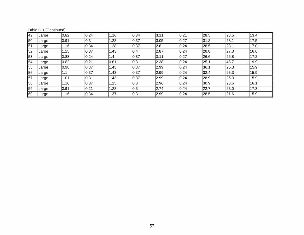
57
Table C.1 (Continued) 49 Large 0.82 0.24 1.16 0.34 3.11 0.21 28.5 28.5 13.4 50 Large 0.91 0.3 1.28 0.37 3.05 0.27 31.8 28.1 17.5 51 Large 1.16 0.34 1.28 0.37 2.8 0.24 28.5 28.1 17.0 52 Large 1.25 0.37 1.43 0.4 2.87 0.24 28.8 27.3 16.6 53 Large 0.88 0.24 1.4 0.37 3.11 0.27 26.6 25.8 17.2 54 Large 0.82 0.21 0.61 0.3 2.38 0.24 25.1 45.7 19.9 55 Large 0.98 0.37 1.43 0.37 2.99 0.24 36.1 25.3 15.9 56 Large 1.1 0.37 1.43 0.37 2.99 0.24 32.4 25.3 15.9 57 Large 1.01 0.3 1.43 0.37 2.99 0.24 28.9 25.3 15.9 58 Large 1.16 0.37 1.25 0.3 2.96 0.24 30.9 23.6 16.1 59 Large 0.91 0.21 1.28 0.3 2.74 0.24 22.7 23.0 17.3 60 Large 1.16 0.34 1.37 0.3 2.99 0.24 28.5 21.6 15.9

58
Table C.2 Field Measurements of Critical Dimensions (Tractors and Trailers)
Vehicle Type Wheelbase (m)
Wheelbase Clearance (m)
Crossover Angle (degree)
1 Tractor 2.62 0.37 27.5 2 Tractor 3.38 0.37 21.6 3 Tractor 3.84 0.4 20.5 4 Tractor 3.41 0.34 19.7 5 Tractor 5.15 0.43 16.5 6 Tractor 3.69 0.3 16.1 7 Trailor 9.51 0.91 18.9 8 Trailor 7.68 0.73 18.8 9 Trailor 8.23 0.76 18.3 10 Trailor 6.89 0.58 16.7 11 Trailor 10.37 0.85 16.2 12 Trailor 9.97 0.79 15.7 13 Trailor 9.24 0.73 15.7 14 Trailor 9.24 0.73 15.7 15 Trailor 10.98 0.82 14.8 16 Trailor 10.98 0.82 14.8 17 Trailor 11.59 0.85 14.6 18 Trailor 10.88 0.79 14.4 19 Trailor 10.06 0.7 13.8 20 Trailor 9.76 0.67 13.6 21 Trailor 10.76 0.73 13.5 22 Trailor 6.83 0.46 13.4 23 Trailor 10.98 0.73 13.2

59
Table C.3 Field Measurements of Critical Dimensions (Single Unit Trucks)
Vehicle Type Wheelbase (m)
Wheelbase Clearance (m)
Rear (m) Rear Clearance (m)
Crossover Angle (degree)
Dept. Angle (m)
1 single unit truck 5.55 0.58 2.59 0.46 20.6 17.6 2 single unit truck 5.12 0.46 2.68 0.49 17.8 18.1 3 single unit truck 4.51 0.37 1.98 0.49 16.3 24.3 4 single unit truck 4.02 0.30 1.71 0.37 14.8 21.3 5 single unit truck 4.45 0.30 1.65 0.37 13.4 22.1 6 single unit truck 3.41 0.21 1.83 0.30 12.3 16.2
Table C.4 Measurements of Critical Dimension (Buses)
Vehicle Type
Wheelbase Front Overhang
Rear Overhang Approach Angle*
Departure Angle*
Crossover Angle*
(m) (inch) (m) (inch) (m) (inch) (degree) (degree) (degree) 1 NABI Model
416 6.7 264 2.2 86 3.0 118 9 9 10
2 NABI Model 40CFW
7.0 276 2.2 86 3.0 118 9 9 10
4 29’ Q-Bus
3.8 151 2.1 81.5 3.0 118.5 8.3 7.9 16.8
5 35’ and 37’ Q-Bus
5.6 221 2.1 81.5 3.0 118.5 8.5 7.6 10
Source: 1, 2 and 3 http://www.trabsut-cebter,cin/NABI/buses 4, and 5 http://www.blue-bird-com/comm.html * Suspension factor has been adjusted.