establishing bresle patch equivalence (iso8502 9 method ... · whilst both the bresle patch test...
TRANSCRIPT
www.elcometer.com Elcometer 130 SSP Bresle Equivalence Page 1 of 22
Establishing Bresle Patch Equivalence (ISO8502-9 Method) for the new Elcometer 130 SSP
1. Foreword The purpose of this test method is to establish equivalence to the Bresle Patch Method for the new
Elcometer 130 SSP, as defined by ISO 8502-9.
Equivalency is to be determined by testing and comparing results of the Elcometer 130 SSP to the method
specified in ISO 8502-9 across a number of salt contaminated steel panels of various blasted profiles.
2. Introduction Soluble salts, which are often invisible to the eye, can result in premature corrosion, leading to coating
failures – resulting in high re-coating, maintenance costs, asset downtime or availability.
In order to show equivalency of measurement between any two test methods it is important to ensure that
no other parameters change except the gauges under test. For equivalency to be established, both gauges
should read a similar value, taking into account the accuracy and resolution of each gauge.
Whilst both the Bresle Patch Test Method and the Elcometer 130 SSP use different techniques, they both
measure the concentration of soluble salts on a substrate using the conductivity method. This requires that
the salts have to first be removed from the substrate using deionised water, and the resulting solution
tested using a conductivity meter. The higher the level of conductivity of the resulting solution, the higher
the level of soluble salt concentration.
As both test methods (Bresle and Elcometer 130 SSP) require the removal of the soluble salts from the
substrate, each instrument must measure on different test areas (as the salt would have been removed
from the first test area).
This requires the development of a repeatable, reproducible and uniform method for doping a clean
substrate.
Research undertaken by Elcometer has established that the NACE SP0508-2010 method for determining a
gauge’s equivalency to the Bresle Patch Method is not valid. The recommended doping method within
NACE SP0508-2010 produces wide variations of salt concentration across a test panel – making
comparisons between instruments impossible. Additionally, some of the requirements set down within
NACE SP0508-2010 require measurements on surfaces that would be wholly unacceptable for a coating to
be applied – namely corroded steel.
With this in mind, Elcometer, with the help of the School of Materials at The University of Manchester (UK),
has developed an automated, repeatable and reproducible doping method which can accurately apply a
wide range of concentrations to a variety of substrates. For more information on the Elcometer Doping
Method see Appendix 1.
www.elcometer.com Elcometer 130 SSP Bresle Equivalence Page 2 of 22
In addition to developing an automated, more consistent doping method, new parameters for establishing
equivalency have been developed which are more appropriate to the industrial application in question,
incorporating salt concentration and surface profile.
In order to ensure impartiality of the test results, Mr C Molloy, an undergraduate in BSc Physics at the
University of Edinburgh, was brought in to independently undertake the tests and generate the report.
3. Method The following test considerations have been used to establish equivalency to the Bresle Test Patch method.
3.1. Surface Salt Concentration The level of ‘acceptable’ threshold concentration levels of soluble salts on a ferrous substrate, within
the Protective Coatings Industry, are as follows:
NAVSEA 009-32 FY-12 30 – 50 mg/m²
NORSOK M-501 20 – 50 mg/m²
DNV RP-F102 20 mg/m²
IMO MSC.215(82) & MSC.244(83) 50 mg/m²
To determine equivalency, this test method will dope panels at five ranges of surface salt concentration
levels:
1) 15 mg/m2 to 25 mg/m2
2) 25 mg/m2 to 35 mg/m2
3) 35 mg/m2 to 45 mg/m2
4) 45 mg/m2 to 55 mg/m2
5) >55 mg/m2
3.2. Salt Ratio Each panel will be immersed in deionised water to remove all residual soluble salts and impurities prior
to the doping process. The salt solution used will be industry recognised reference for salts, as defined
by NACE SP0508-2010.
The following mass ratio of salts shall be used:
24.3% Na2SO4
22.1% NaNO3
53.6% NaCl
Deionised water with a maximum conductivity of 3.00 µS/cm shall be used for both the Bresle Patch
Test Method and the Elcometer 130 SSP. Any background conductivity will be measured, recorded and
deducted from the measurements.
www.elcometer.com Elcometer 130 SSP Bresle Equivalence Page 3 of 22
3.3. Surface Profile Common practice within the United States of America dictates that coatings are only applied to blast
cleaned surfaces, free of rust or corrosion. Blasted profiles within the Protective Coatings Industry
typically have a nominal peak-to-valley height of either 50 µm, 75 µm or 100 µm (2.0, 3.0 and 4.0 mils).
European practice may also apply a protective coating up to a nominal 150 µm (6 mils). This practice is
being considered in the US as well.
To determine equivalency, this test method will dope panels at the following nominal steel grit blast
profiles:
25 to 50 µm (1.0 to 2.0 mils)
50 to 75 µm (2.0 to 3.0 mils)
75 to 150 µm (3.0 to 6.0 mils)
In addition to blasted profiles, a clean coated panel will also be tested to establish equivalency for
inter-coat assessment.
The blasted profile of each uncoated steel panel will be measured using a certified Elcometer 224C
Digital Surface Profile Gauge (using the average of 40 measurements on each panel), to determine the
average peak-to-valley height, in accordance with ASTM D 4417 Method B.
3.4. Preparation of Salt Contaminated Test Panels The test panels shall be prepared to the specified surface salt density levels using the following
parameters:
Test panel size: 300 x 400 mm (11.81 x 15.75 inches)
Clean the test panels via immersion in deionised water
Dry the panel rapidly by blowing off the water with a heat gun (to reduce flash rusting).
Each test panel will be nominally contaminated as follows:
o 3 µl of salt solution spaced on a 4 mm grid across the test panel.
3.5. Method of Doping of Test Panels This section lists the doping method of the test panel.
Place the test panels onto a heating element
Set the heating element’s temperature controller to 70 °C and leave the temperature to
stabilise for two minutes after the temperature controller has met the target value.
Initiate the robot software with the gridded programme which takes just short of 3 hours to
complete.
Upon completion remove the panel from the heating element (protective gloves maybe
required!)
The Panels will be carried to a nearby test area in an enclosed plastic box.
The Panels will be kept in the enclosed plastic box until they are tested.
The measurements will be taken within 72 hours of the completion of the salt contamination
process.
All measurements will be completed in the same test area.
www.elcometer.com Elcometer 130 SSP Bresle Equivalence Page 4 of 22
B2
B1
B4
B3
FP1
B2
B1
B4 &
B2
B3 &
B1
FP1
B2
B1
B4
B3
FP1
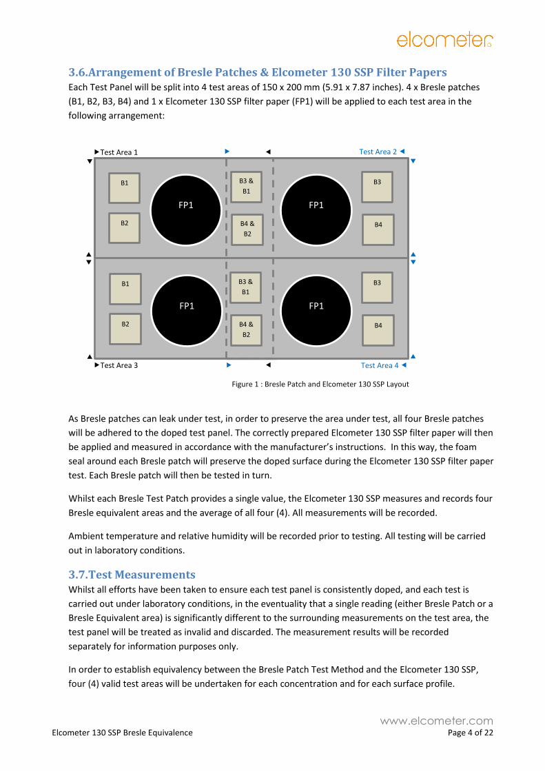
3.6. Arrangement of Bresle Patches & Elcometer 130 SSP Filter Papers Each Test Panel will be split into 4 test areas of 150 x 200 mm (5.91 x 7.87 inches). 4 x Bresle patches
(B1, B2, B3, B4) and 1 x Elcometer 130 SSP filter paper (FP1) will be applied to each test area in the
following arrangement:
As Bresle patches can leak under test, in order to preserve the area under test, all four Bresle patches
will be adhered to the doped test panel. The correctly prepared Elcometer 130 SSP filter paper will then
be applied and measured in accordance with the manufacturer’s instructions. In this way, the foam
seal around each Bresle patch will preserve the doped surface during the Elcometer 130 SSP filter paper
test. Each Bresle patch will then be tested in turn.
Whilst each Bresle Test Patch provides a single value, the Elcometer 130 SSP measures and records four
Bresle equivalent areas and the average of all four (4). All measurements will be recorded.
Ambient temperature and relative humidity will be recorded prior to testing. All testing will be carried
out in laboratory conditions.
3.7. Test Measurements Whilst all efforts have been taken to ensure each test panel is consistently doped, and each test is
carried out under laboratory conditions, in the eventuality that a single reading (either Bresle Patch or a
Bresle Equivalent area) is significantly different to the surrounding measurements on the test area, the
test panel will be treated as invalid and discarded. The measurement results will be recorded
separately for information purposes only.
In order to establish equivalency between the Bresle Patch Test Method and the Elcometer 130 SSP,
four (4) valid test areas will be undertaken for each concentration and for each surface profile.
B2
B1
B4 &
B2
B3 &
B1
FP1
Figure 1 : Bresle Patch and Elcometer 130 SSP Layout
Test Area 1
Test Area 3
Test Area 2
Test Area 4
www.elcometer.com Elcometer 130 SSP Bresle Equivalence Page 5 of 22
3.8. Background contamination Whilst every effort will be made to clean each test panel prior to doping (immersion in deionised
water), there are other background contaminants to take into consideration:
3.8.1. Bresle patch contamination
Bresle patches can suffer from different levels of background contamination. The following
method will be used to determine the background contamination of the Bresle patch batch.
Bresle patches from boxes of 25 will be used. As every doped test panel will require 12
Bresle patches, a spare Bresle patch will be available each time that the testing of two test
panels is completed. This spare Bresle patch will be used to measure the Bresle patch
background contamination.
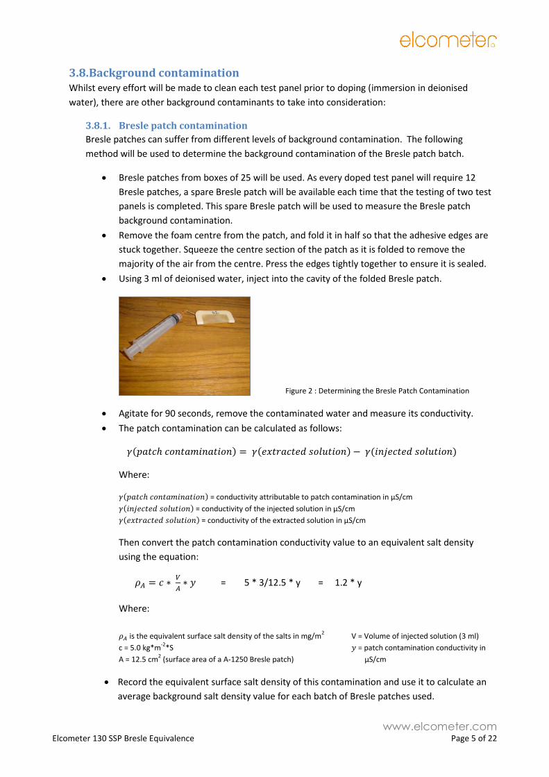
Remove the foam centre from the patch, and fold it in half so that the adhesive edges are
stuck together. Squeeze the centre section of the patch as it is folded to remove the
majority of the air from the centre. Press the edges tightly together to ensure it is sealed.
Using 3 ml of deionised water, inject into the cavity of the folded Bresle patch.
Figure 2 : Determining the Bresle Patch Contamination
Agitate for 90 seconds, remove the contaminated water and measure its conductivity.
The patch contamination can be calculated as follows:
𝛾(𝑝𝑎𝑡𝑐ℎ 𝑐𝑜𝑛𝑡𝑎𝑚𝑖𝑛𝑎𝑡𝑖𝑜𝑛) = 𝛾(𝑒𝑥𝑡𝑟𝑎𝑐𝑡𝑒𝑑 𝑠𝑜𝑙𝑢𝑡𝑖𝑜𝑛) − 𝛾(𝑖𝑛𝑗𝑒𝑐𝑡𝑒𝑑 𝑠𝑜𝑙𝑢𝑡𝑖𝑜𝑛)
Where:
𝛾(𝑝𝑎𝑡𝑐ℎ 𝑐𝑜𝑛𝑡𝑎𝑚𝑖𝑛𝑎𝑡𝑖𝑜𝑛) = conductivity attributable to patch contamination in µS/cm
𝛾(𝑖𝑛𝑗𝑒𝑐𝑡𝑒𝑑 𝑠𝑜𝑙𝑢𝑡𝑖𝑜𝑛) = conductivity of the injected solution in µS/cm
𝛾(𝑒𝑥𝑡𝑟𝑎𝑐𝑡𝑒𝑑 𝑠𝑜𝑙𝑢𝑡𝑖𝑜𝑛) = conductivity of the extracted solution in µS/cm
Then convert the patch contamination conductivity value to an equivalent salt density
using the equation:
𝜌𝐴 = 𝑐 ∗ 𝑉
𝐴∗ 𝑦 = 5 * 3/12.5 * y = 1.2 * y
Where:
𝜌𝐴 is the equivalent surface salt density of the salts in mg/m2 V = Volume of injected solution (3 ml)
c = 5.0 kg*m-2
*S 𝑦 = patch contamination conductivity in
A = 12.5 cm2 (surface area of a A-1250 Bresle patch) µS/cm
Record the equivalent surface salt density of this contamination and use it to calculate an
average background salt density value for each batch of Bresle patches used.
www.elcometer.com Elcometer 130 SSP Bresle Equivalence Page 6 of 22
3.8.2. Deionised Water concentration
Deionised water with a maximum conductivity of 3.00 µS/cm shall be used for both the Bresle
Patch Test Method and the Elcometer 130 SSP tests. Any background conductivity will be
measured, recorded and deducted from the Bresle Patch Test Method measurements. The
Elcometer 130 SSP will automatically adjust its measurement to take account of this background
conductivity once the “offset procedure” has been followed. See section 3.8.3
3.8.3. Elcometer 130 SSP filter paper and water, offset procedure:
As per the manufacturer’s operating instructions, when a new box of filter papers is opened or a
new container of deionised water is used, the filter paper and deionised water offset needs to be
set on the Elcometer 130 SSP.
Extract, with tweezers, a filter paper from the box.
Place the dry filter paper onto the Elcometer 130 magnetic disc - which has been cleaned
using deionised water and sensor wipes.
Fill the syringe completely with deionised water and discard it. Perform this rinsing three
times.
Fill the syringe with 1.6 ml of deionised water. Spread the water, from the syringe, evenly
across the whole of the Elcometer 130 SSP filter paper. Best achieving by starting in the
middle of the filter paper and working out two the edge using multiple drops. Then tilt the
magnetic disc as necessary until the water is evenly spread across the filter paper.
Place the magnetic disc with filter paper onto the Elcometer 130 SSP measuring electrodes
(which has been cleaned using deionised water and sensor wipes).
On the gauge select Menu\Setup\Calibration\Calibration Offset and follow the screen
instructions. When complete the gauge reports “Calibrated”, press Ok and return to the
Normal Reading Screen.
With the magnetic disc and filter paper on the measuring electrodes take a reading. Check
that the reading is no more than 1 – 2 mg/m2 (0.1 – 0.2µg/cm2)
www.elcometer.com Elcometer 130 SSP Bresle Equivalence Page 7 of 22
4. Data Analysis When the results are taken they will conform to the following criteria:
4.1. Elcometer130SSP to Bresle Patch Data analysis To be deemed equivalent to the Bresle Patch Method the Elcometer 130SSP results shall meet the
following requirements:
The average of the four Bresle readings in each test area will be within ±9mg/m2 of the average
filter paper reading for that area (which ever is the greatest).
4.2. Conversion Factor An internal conversion factor will be used to bring the Elcometer 130 SSP results in line with the
measured Bresle Patch Method results across all surfaces and all salt densities. The conversion factor
will not be reported.
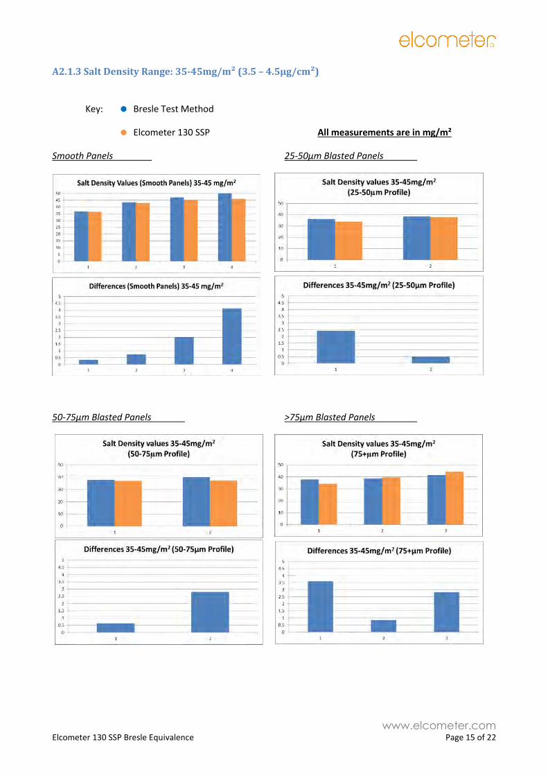
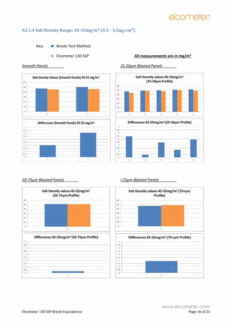
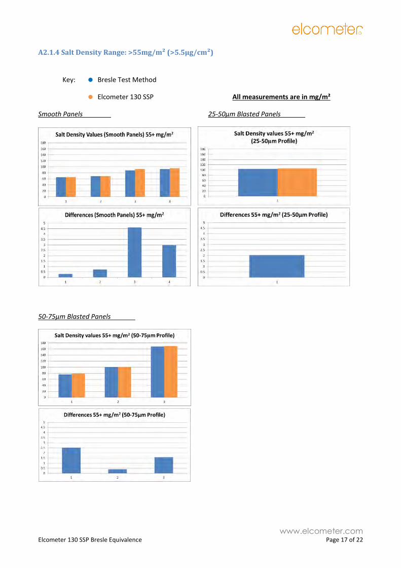
5. Results Summary The Results displayed in Appendix two represent the average values of 5 test areas – a test area is defined
as 4 Bresle Patches and 1 Elcometer 130 SSP filter paper (which is the average of 4 Bresle equivalent areas).
Each column in the graphs in Appendix 2 represents the average of 5 individual tests.
6. Conclusion The Elcometer 130 SSP has undergone extensive side by side comparison testing against the Bresle Test
Patch Method.
Background (inherent) contamination within the Bresle Test Patch has shown that the Bresle
Test Patch has a background contamination range of 0.88µg/cm² - see Appendix A2.2
The variation in readings between the Elcometer 130SSP and the Bresle Test method are
significantly within the background contamination range of the Bresle Patches (0.88µg/cm²);
being less than 0.41µg/cm² for concentrations below 8.0µg/cm², and less than 0.46µg/cm²
across concentrations below 16.5µg/cm²
No consideration has been taken into account with regards to the measurement accuracy of
the Horiba Conductivity meter, which can further affect the Bresle Test Patch Method
variations.
It can therefore be concluded that, following extensive testing across numerous salt concentrations, on
smooth and a wide range of grit blast profiled test panels, that the Elcometer 130 SSP, when set up in
the gauge’s Bresle Equivalence Mode, provides an equivalence to the Bresle Test Method in accordance
with ISO8502-9.
www.elcometer.com Elcometer 130 SSP Bresle Equivalence Page 8 of 22
Appendix 1: - Coating Panels With Salt
The Bresle method of testing is a destructive test, in that the process of testing removes the salt. This
means that the test can not be repeated again in exactly the same position. Therefore before Bresle
equivalence can be tested, it is necessary to produce panels that are evenly covered in salt so that Bresle
patches and the candidate method can reasonable be expected to give the same measurement when
placed adjacent to each other on a panel.
However coating a panel evenly with salt is a difficult task to achieve. One issue is that the salt needs to
adhere to the surface, so simply placing it in a dry state does not work, even if a mechanism for doing so
was to be devised. This problem can be overcome by making a solution using the salt. The solution can then
be applied to the surface and allowed to dry, leaving the salt behind on the surface of the panel. But
applying salt evenly using a solution is not easy. The solution will tend to flow to the lowest point on a
panel and form into pools as it dries. Also, if given time, the salt will start to form into crystals, creating high
concentration zones.
Several methods have been investigated to overcome these problems:-
A1.1 Manual Glass Rod Method A1.1.1 Method – This method is suggested in NACE SP0508-2010, which states “Apply an
appropriate volume of doping solution in a column down the centre of the test panel using a pipette
(1 mL has been found appropriate for 200 x 150 mm [8 x 6 in] test panel). Immediately spread the
doping solution evenly over the entire test panel with an approximately 125 mm (5 in) in length by 3
mm (0.125 in) outside diameter (OD) glass rod. The glass rod shall be continuously wiped (but not
rotated) over the test panel to keep the doping solution uniformly distributed until the liquid dries. A
gentle stream of dry, compressed air may then be blown over the test panel to accelerate drying”
A1.1.2 Rationale – Moving the solution uniformly over the panel as it dries will ensure that the
same amount of solution dries in each area of the panel, and so deposits the same amount of salt
in each area of the panel.
A1.1.3 Result – This method failed to produce a consistent coating of salt. It was not possible to
visually determine that the solution depth was even as it dried, and as the solution volume reduced
it immediately clumped into pools, after the glass rod had passed over it. Also it was a very time
consuming process to perform manually.
A1.2 Automatic Glass Rod Method A1.2.1 Method – This method is the same as the ‘Manual Glass Rod Method’ above, but using an
automatic film applicator to continually move the glass rod over the panel surface as the solution
dries. The automatic film applicator also has a heated base to heat the panel and so speed up the
drying process.
A1.2.2 Rationale – The automatic film applicator will move the glass rod in a consistent and
repetitive motion, thus ensuring that the glass rod is passed over all areas of the panel equally.
A1.2.3 Result – This method was also unsuccessful. It still failed to maintain an even depth of
solution over the surface as it dried, as the solution still clumped into pools as it dried.
www.elcometer.com Elcometer 130 SSP Bresle Equivalence Page 9 of 22
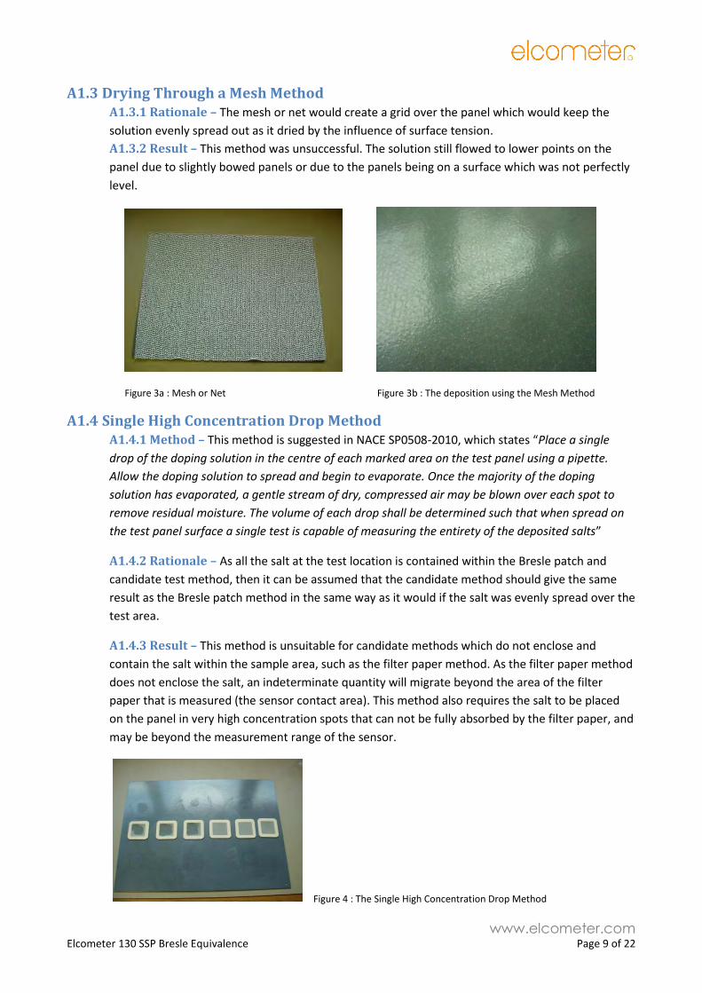
A1.3 Drying Through a Mesh Method A1.3.1 Rationale – The mesh or net would create a grid over the panel which would keep the
solution evenly spread out as it dried by the influence of surface tension.
A1.3.2 Result – This method was unsuccessful. The solution still flowed to lower points on the
panel due to slightly bowed panels or due to the panels being on a surface which was not perfectly
level.
Figure 3a : Mesh or Net Figure 3b : The deposition using the Mesh Method
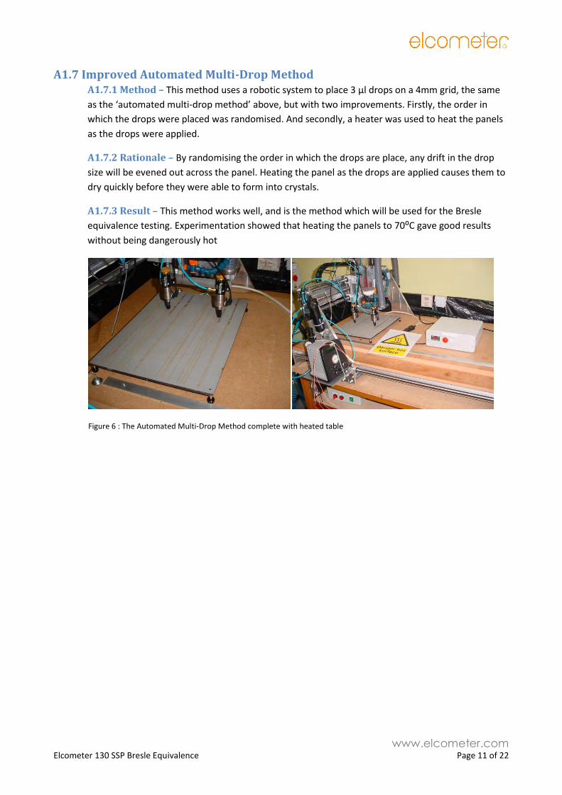
A1.4 Single High Concentration Drop Method A1.4.1 Method – This method is suggested in NACE SP0508-2010, which states “Place a single
drop of the doping solution in the centre of each marked area on the test panel using a pipette.
Allow the doping solution to spread and begin to evaporate. Once the majority of the doping
solution has evaporated, a gentle stream of dry, compressed air may be blown over each spot to
remove residual moisture. The volume of each drop shall be determined such that when spread on
the test panel surface a single test is capable of measuring the entirety of the deposited salts”
A1.4.2 Rationale – As all the salt at the test location is contained within the Bresle patch and
candidate test method, then it can be assumed that the candidate method should give the same
result as the Bresle patch method in the same way as it would if the salt was evenly spread over the
test area.
A1.4.3 Result – This method is unsuitable for candidate methods which do not enclose and
contain the salt within the sample area, such as the filter paper method. As the filter paper method
does not enclose the salt, an indeterminate quantity will migrate beyond the area of the filter
paper that is measured (the sensor contact area). This method also requires the salt to be placed
on the panel in very high concentration spots that can not be fully absorbed by the filter paper, and
may be beyond the measurement range of the sensor.
Figure 4 : The Single High Concentration Drop Method

www.elcometer.com Elcometer 130 SSP Bresle Equivalence Page 10 of 22
A1.5 Manual Multi-Drop Method A1.5.1 Method – This method is similar to the ‘single high concentration drop’ method above. But,
the salt is placed evenly over the entire panel in a grid of low concentration drops. The drops must
be placed on a fine grid for this method to approximate to a continuous even coating of salt. A grid
size of 4mm was decided upon, as this was the minimum grid size at which 3 µl drops of solution
could be placed without touching and running into each other, and 3 µl was the minimum drop size
that could be repeatable produced.
A1.5.2 Rationale – A surface which is covered with a fine grid of salt drops that almost touch, will
give measurements that are the same as a surface with a continuous even coating of salt when
tested using the Bresle method or a candidate method.
A1.5.3 Result – This method gave reasonable results. But it was not possible to maintain a perfect
grid pattern by hand, as slight variations in the position, angle and height, caused drops to miss the
grid and run in to each other creating small pools of solution and gaps in the grid. Also this is a very
tedious process to perform manually taking about 3 hours to place the approximately 7,500 drops
required for a 30 x 40 cm panel. It was also suspected that the manual handling of the panel for
several hours was resulting in areas of accidental contamination.
Figure 5 : The Manual Multi-Drop Method
A1.6 Automated Multi-Drop Method A1.6.1 Method – This method uses a robotic system to place 3 µl drops on a 4mm grid, the same
as the ‘manual multi-drop method’ above.
A1.6.2 Rationale – An automated system will be able to place the drops continuously and
accurately on the 4mm grid. Also there will be less opportunity for accidental contamination as
there is less manual handling.
A1.6.3 Result – This method gave good results, but some issues were still apparent. One problem
was that sometimes the drop dispensing value’s drop size drifted during the course of the doping
process. This drift in drop size caused a gradient in salt concentration to occur from the point at
which the salt deposition started to the point where it finished. Another problem was that the time
taken for the salt solution to dry caused variations in the way that it was deposited. If the salt was
allowed to dry slowly, it would form into high concentration crystals. But the salt didn’t dry in a
consistent way across the panel. This resulted in areas where the salt had dried into very
concentrated spots or rings, which were not easily removed by the test methods. This resulted in
varying measurements across the panel.
www.elcometer.com Elcometer 130 SSP Bresle Equivalence Page 11 of 22
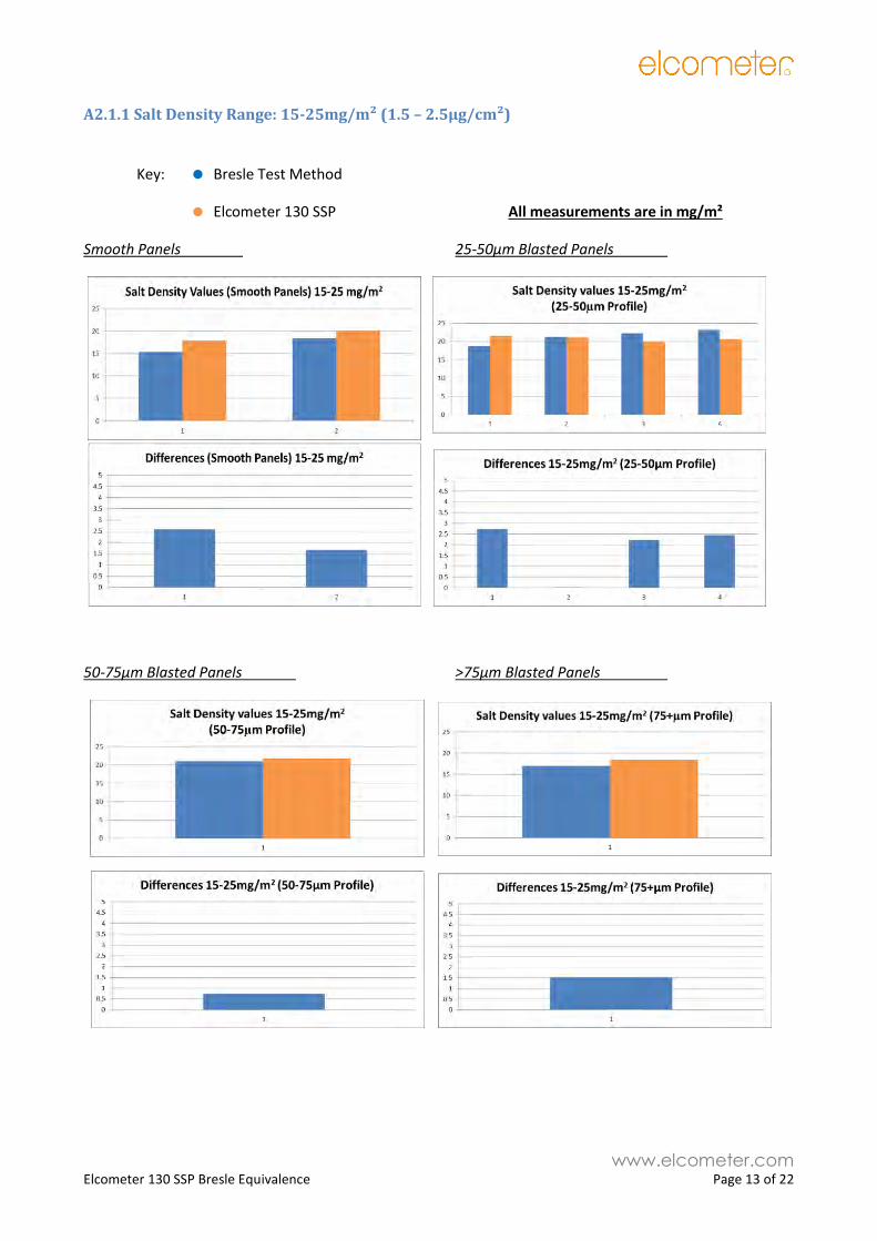
A1.7 Improved Automated Multi-Drop Method A1.7.1 Method – This method uses a robotic system to place 3 µl drops on a 4mm grid, the same
as the ‘automated multi-drop method’ above, but with two improvements. Firstly, the order in
which the drops were placed was randomised. And secondly, a heater was used to heat the panels
as the drops were applied.
A1.7.2 Rationale – By randomising the order in which the drops are place, any drift in the drop
size will be evened out across the panel. Heating the panel as the drops are applied causes them to
dry quickly before they were able to form into crystals.
A1.7.3 Result – This method works well, and is the method which will be used for the Bresle
equivalence testing. Experimentation showed that heating the panels to 70⁰C gave good results
without being dangerously hot
Figure 6 : The Automated Multi-Drop Method complete with heated table

www.elcometer.com Elcometer 130 SSP Bresle Equivalence Page 12 of 22
Appendix 2 – Results
A2.1 Elcometer 130 SSP to Bresle Method Equivalence
The Elcometer 130 SSP has undergone extensive side by side comparison testing against the Bresle Test
Patch Method.
Background (inherent) contamination within the Bresle Test Patch has shown that the Bresle
Test Patch has a background contamination range of 0.88µg/cm² - see Appendix A2.2
The variation in readings between the Elcometer 130SSP and the Bresle Test method are
significantly within the background contamination range of the Bresle Patches (0.88µg/cm²);
being less than 0.41µg/cm² for concentrations below 8.0µg/cm², and less than 0.46µg/cm²
across concentrations below 16.5µg/cm²
No consideration has been taken into account with regards to the measurement accuracy of the
Horiba Conductivity meter, which can further affect the Bresle Test Patch Method variations.
It can therefore be concluded that, following extensive testing across numerous salt concentrations, on
smooth and a wide range of grit blast profiled test panels, that the Elcometer 130 SSP, when set up in
the gauge’s Bresle Equivalence Mode, provides an equivalence to the Bresle Test Method in accordance
with ISO8502-9.
www.elcometer.com Elcometer 130 SSP Bresle Equivalence Page 13 of 22
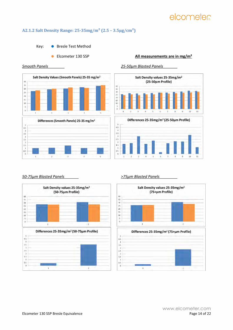
A2.1.1 Salt Density Range: 15-25mg/m² (1.5 – 2.5µg/cm²)
Key: Bresle Test Method
Elcometer 130 SSP All measurements are in mg/m²
Smooth Panels 25-50µm Blasted Panels
50-75µm Blasted Panels >75µm Blasted Panels
www.elcometer.com Elcometer 130 SSP Bresle Equivalence Page 14 of 22
A2.1.2 Salt Density Range: 25-35mg/m² (2.5 – 3.5µg/cm²)
Key: Bresle Test Method
Elcometer 130 SSP All measurements are in mg/m²
Smooth Panels 25-50µm Blasted Panels
50-75µm Blasted Panels >75µm Blasted Panels
www.elcometer.com Elcometer 130 SSP Bresle Equivalence Page 15 of 22
A2.1.3 Salt Density Range: 35-45mg/m² (3.5 – 4.5µg/cm²)
Key: Bresle Test Method
Elcometer 130 SSP All measurements are in mg/m²
Smooth Panels 25-50µm Blasted Panels
50-75µm Blasted Panels >75µm Blasted Panels
www.elcometer.com Elcometer 130 SSP Bresle Equivalence Page 16 of 22
A2.1.4 Salt Density Range: 45-55mg/m² (4.5 – 5.5µg/cm²)
Key: Bresle Test Method
Elcometer 130 SSP All measurements are in mg/m²
Smooth Panels 25-50µm Blasted Panels
50-75µm Blasted Panels >75µm Blasted Panels
www.elcometer.com Elcometer 130 SSP Bresle Equivalence Page 17 of 22
A2.1.4 Salt Density Range: >55mg/m² (>5.5µg/cm²)
Key: Bresle Test Method
Elcometer 130 SSP All measurements are in mg/m²
Smooth Panels 25-50µm Blasted Panels
50-75µm Blasted Panels

www.elcometer.com Elcometer 130 SSP Bresle Equivalence Page 18 of 22
A2.2 Bresle Patch Background Contamination Results
All Bresle Test Patches used during the contamination testing were taken from Batch / Lot Number 82987
and Batch / Lot Number 84116.
Bresle Test # 1 2 3 4 5 6 7 8 9 10 11 12 13 14 15 16 17 18 19 20 21
AVG 9 10 8.11 7.66 9 7 10 9 6 6 5 6 6.11 8 7 5 8 7 4 11 10
AVG-BACK 7 8 6.11 5.66 7 5 8 7 4 4 3 4 4.11 6 5 3 6 5 2 9 8
Background (mg/m2) 8.4 9.6 7.33 6.79 8.4 6 9.6 8.4 4.8 4.8 3.6 4.8 4.93 7.2 6 3.6 7.2 6 2.4 10.8 9.6
Bresle Test # 22 23 24 25 26 27 28 29 30 31 32 33 34 35 36 37 38 39 40 41 42
AVG 7 7 8 7.22 6.11 11 6 6 7.55 8 7 7 11 7 7 9 5 9 5.5 5 9
AVG-BACK 5 5 6 6.11 4.11 9 4 4 5.55 6 5 5 9 5 5 7 3 7 3.5 3 7
Background (mg/m2) 6 6 7.2 7.33 4.93 10.8 4.8 4.8 6.66 7.2 6 6 10.8 6 6 8.4 3.6 8.4 4.2 3.6 8.4
Background Water Contamination: 2.0 mg/m²
Salt Conversion Factor: 1.2 mg/m²
Max Bresle Background Contamination: 10.8 mg/m²
Min Bresle Background Contamination: 2.4 mg/m²
Bresle Background Contamination Range: 8.8 mg/m²
Average Bresle Background Contamination: 6.7 mg/m²
www.elcometer.com Elcometer 130 SSP Bresle Equivalence Page 19 of 22
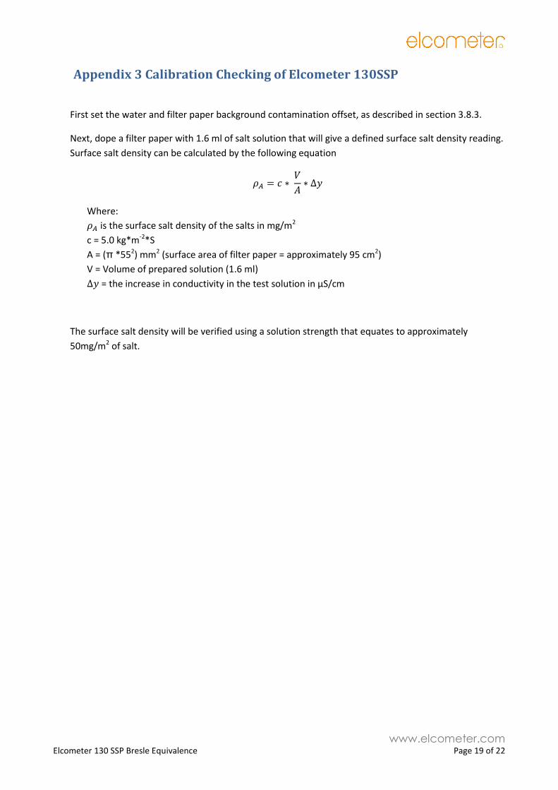
Appendix 3 Calibration Checking of Elcometer 130SSP
First set the water and filter paper background contamination offset, as described in section 3.8.3.
Next, dope a filter paper with 1.6 ml of salt solution that will give a defined surface salt density reading.
Surface salt density can be calculated by the following equation
𝜌𝐴 = 𝑐 ∗ 𝑉
𝐴∗ ∆𝑦
Where:
𝜌𝐴 is the surface salt density of the salts in mg/m2
c = 5.0 kg*m-2*S
A = (π *552) mm2 (surface area of filter paper = approximately 95 cm2)
V = Volume of prepared solution (1.6 ml)
∆𝑦 = the increase in conductivity in the test solution in µS/cm
The surface salt density will be verified using a solution strength that equates to approximately
50mg/m2 of salt.
www.elcometer.com Elcometer 130 SSP Bresle Equivalence Page 20 of 22
Appendix 4 - Bresle Patch Method – ISO 8502-9 (from NACE SP0508)
A4.1) Before each measurement or series of measurements and at a frequency of no less than every 4
hours, the conductivity meter will have its calibration verified. Adjust the conductivity meter as
necessary to achieve accurate measurement.
A4.2) Fill the syringe completely with deionised water and use it to rinse the conductivity cell. Perform this
rinsing three times to clean both the syringe and the conductivity cell.
Note: this is a slight modification to ISO 8502-9 which has the cleaning of the syringe and the
cleaning of the conductivity cell as two separate operations.
A4.3) Measure the conductivity of this test solution and record the value.
A4.4) Take an A-1250 Bresle patch, remove its protective backing along with its foam centre.
A4.5) Apply the Bresle patch to the surface pressing firmly around the perimeter of the patch to ensure a
complete seal.
A4.6) Insert the needle of the syringe into the Bresle patch at an angle of 30° to the test surface near the
outer edge of the patch so that it passes through the adhesive foam body into the test compartment
and remove the air from the patch. Fill the syringe with 3 ml of deionised water. Replace the syringe
needle into the Bresle patch and inject the 3 ml of water into the patch.
A4.7) Remove the syringe needle to the edge of patch so that it is still plugging the hole, and preventing
water from leaking. Immediately but gently, rub the surface of the patch for 90 seconds. Extract the
sample solution from the patch, with the syringe, within 15 seconds of completion of the rubbing.
Note: This is a slight modification to ISO 8502-9 which states “Remove the syringe from the Bresle
patch.”
A4.8) Inject the sample solution directly into the conductivity cell. Rinse the cell three times with the same
test solution to be measured before taking nine readings. Record the conductivity value of the
sample solution.
Note: Although not stated this infers we take the average of the nine readings.
A4.9) Calculate the increase in conductivity in the sample solution using the equation below.
∆𝛾 = 𝛾(𝑒𝑥𝑡𝑟𝑎𝑐𝑡𝑒𝑑 𝑠𝑜𝑙𝑢𝑡𝑖𝑜𝑛) − 𝛾(𝑖𝑛𝑗𝑒𝑐𝑡𝑒𝑑 𝑠𝑜𝑙𝑢𝑡𝑖𝑜𝑛)
Where:
𝛾(𝑖𝑛𝑗𝑒𝑐𝑡𝑒𝑑) = conductivity of the injected solution in µS/cm
𝛾(𝑒𝑥𝑡𝑟𝑎𝑐𝑡𝑒𝑑 𝑠𝑜𝑙𝑢𝑡𝑖𝑜𝑛) = conductivity of the extracted solution in µS/cm
www.elcometer.com Elcometer 130 SSP Bresle Equivalence Page 21 of 22
A5.10) Surface salt density can be calculated by the following equation
𝜌𝐴 = (𝑐 ∗ 𝑉
𝐴∗ 𝑦) - 𝜌𝐵 = (5 * 3/12.5 * y) - 𝜌𝐵 = (1.2 * y) - 𝜌𝐵
Where:
𝜌𝐴 is the surface salt density of the salts in mg/m2
c = 5.0 kg*m-2*S
A = 12.5 cm2 (surface area of a A-1250 Bresle patch)
V = Volume of injected solution (3 ml)
𝑦 = the increase in conductivity in the sample solution in µS/cm
𝜌𝐵 is the average Bresle patch background contamination for the current batch of Bresle patches
(See section 3.8.1)
Note: 7.2 mg/m2 (from 6 µS/cm solution) can be added back to account for historical salt
contamination specifications that have been developed to account for the ionic contamination
offset introduced by the Bresle method itself. The offset factor of 6 µS/cm used is consistent with
ISO 8502-9 and confirmed by laboratory tests of Bresle patches from multiple sources. This
equivalence test will not add this historical offset, but if required, data will be produced showing
the results with this offset added to the Bresle results, and an equivalent offset added to the
Elcometer 130 SSP results.
www.elcometer.com Elcometer 130 SSP Bresle Equivalence Page 22 of 22
Appendix 5 – Measurement Equipment Used.
5.1 Elcometer 130 SSP Gauge Serial number PK15377
5.2 Bresle Patches Elcometer 135B A-1250 Bresle Patches. Batch Numbers 82987 and 84116
5.3 Profile Measurement Elcometer 224C-TI Serial Number RD10004
Certificate Number 224-RD10004-G
5.4 Environmental Measurement Elcometer G319----T Serial Number RE11596 Calibration
Certificate Number 24191 - Date 9th June 2015
5.5 Conductivity Measurement Horiba LAQUAtwin Model B-771 S/N PC44EE86 – Model S070 S/N D754V1A6
Jenway Model 4510 S/N 34200
5.6 Conductivity Calibration Solution Horiba Standard Solution 1.41mS/cm Model Y071L Potassium chloride (nearly 0.07%)
Cole-Palmer Traceable Conductivity Standard Solution 10.27 μS/cm Cert No 4065-6859702
Cole-Palmer Traceable Conductivity Standard Solution 101.1μS/cm Cert No 4066-6906411