establishing a serial bridge application note -...
TRANSCRIPT

Establishing a Serial Bridge eBUS SDK Application Note
In some systems, you may be required to use an existing third-party camera configuration application (for example, the software application that was provided with the camera), a third-party application relying on a Camera Link DLL, or a Camera Link camera, shipped with a CLProtocol DLL. In each of these cases, the system requires that applications send serial commands to a camera through a Pleora video interface, such as an embedded video interface or external frame grabber. Pleora’s eBUS SDK contains functionality that allows you to establish a bridge to facilitate communication between the eBUS SDK and a camera.
This application note covers the following scenarios, in which a Serial Communication Bridge is used to send serial commands to the camera through a Pleora video interface:
• Serial port (also known as a COM port) communication. You are using a third-party camera configuration application that assumes that you use a serial port on your computer to send serial commands to the camera, or you would like to use a joystick connected to a serial port on your computer to control the camera.
• Camera Link DLL communication. You are using a third-party camera configuration application that requires that you use a Camera Link DLL to send serial commands to the camera.
• CLProtocol DLL and GenICam CLProtocol. The camera manufacturer has provided a CLProtocol DLL that allows you to configure and monitor settings within the camera using GenICam.
The following topics are covered in this application note:
• ‘‘About the eBUS SDK Serial Communication Bridge’’ on page 2
• ‘‘Option 1: Serial Port Link’’ on page 3
• ‘‘Option 2: Pleora Camera Link DLL’’ on page 8
• ‘‘Option 3: GenICam CLProtocol’’ on page 13
Establishing a Serial Bridge Application Note 2
About the eBUS SDK Serial Communication Bridge
The Serial Communication Bridge feature introduces a new SDK class, PvSerialBridge, which allows the SDK to receive serial commands from a camera configuration application and send them through the video interface to the camera. eBUS Player (a sample viewing and configuration application that is included with the eBUS SDK) includes a serial bridge manager that you can use to configure a serial bridge for any of the video interface’s serial ports.
The Serial Communication Bridge feature is only available for the Windows operating system.
The devices (with which serial communication is established) that are mentioned in this application note may be any type of device; however the most common devices are cameras containing Pleora’s interface technology. In this application note, the term video interface refers to a Pleora external frame grabber or embedded video interface. The device attached to the video interface is referred to as the camera.
The Serial Communication Bridge is used to interface software running on the host to the video interface’s serial port. The bridge is owned and controlled by the eBUS SDK application, which is connected to the video interface.
The camera configuration application usually runs in a separate process (that is, in a separate process from eBUS Player) and interacts with the bridge through a virtual serial port link or the Pleora Camera Link DLL.
When a Serial Communication Bridge is started, the following actions are performed:
• The bridge receives serial data from the camera control software and sends it to the video interface using the GigE Vision protocol’s command link. The video interface then sends the serial data to the camera.
• The video interface receives serial data from the camera. It then sends this data to the bridge using the GigE Vision protocol’s messaging channel. The bridge then makes the data available to the camera configuration application.
With the bridge, the camera configuration application communicates with the serial port link or the Pleora Camera Link DLL as if the camera were directly attached to the computer. The camera configuration application communicates with the camera through the video interface over a network connection.
The GenICam CLProtocol scenario does not define a basic bridge type like the serial port link or the Pleora Camera Link DLL. It replaces the camera configuration application with a GenICam node map interfaced to a CLProtocol DLL.
There are two ways in which you can configure the Serial Communication Bridge for each of the video interface’s serial ports:
• eBUS Player (the sample viewing and configuration application that is included with the eBUS SDK)
• An application created using the eBUS SDK API
Establishing a Serial Bridge Application Note 3
Option 1: Serial Port Link
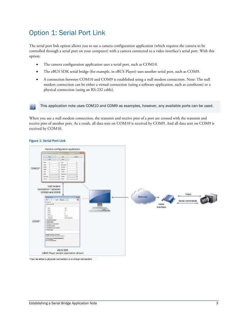
The serial port link option allows you to use a camera configuration application (which requires the camera to be controlled through a serial port on your computer) with a camera connected to a video interface’s serial port. With this option:
• The camera configuration application uses a serial port, such as COM10.
• The eBUS SDK serial bridge (for example, in eBUS Player) uses another serial port, such as COM9.
• A connection between COM10 and COM9 is established using a null modem connection. Note: The null modem connection can be either a virtual connection (using a software application, such as com0com) or a physical connection (using an RS-232 cable).
This application note uses COM10 and COM9 as examples, however, any available ports can be used.
When you use a null modem connection, the transmit and receive pins of a port are crossed with the transmit and receive pins of another port. As a result, all data sent on COM10 is received by COM9. And all data sent on COM9 is received by COM10.
Figure 1: Serial Port Link
Establishing a Serial Bridge Application Note 4
Establishing a Null Modem Connection For the camera configuration application to communicate with the eBUS SDK using a serial port, you must establish a null modem connection. There are two options for establishing a null modem connection:
• Virtual null modem connection using a software application (such as com0com), which creates a pair of virtual serial ports that act like a physical null modem connection.
• Physical connection using a null modem cable. If your computer has two available serial ports (either on the motherboard, via a PCIe expansion card, or through a USB-based adapter), you can create a physical null modem connection by connecting the two ports with a serial null modem cable (or a serial cable with a null modem adapter). Or optionally, you can create a physical connection using two computers by connecting a serial null modem cable (or a serial cable with a null modem adapter) to a serial port on each computer. When you are using two computers, you need to install the camera configuration application on one computer and install the eBUS SDK on the other computer.
To establish a virtual null modem connection using a software application (com0com)
1. Download and install virtual null modem software. This procedure uses com0com (which is available as a signed version for Windows 7), which is available at http://com0com.sourceforge.net/.
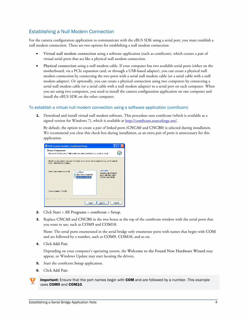
By default, the option to create a pair of linked ports (CNCA0 and CNCB0) is selected during installation. We recommend you clear this check box during installation, as an extra pair of ports is unnecessary for this application.
2. Click Start > All Programs > com0com > Setup.
3. Replace CNCA0 and CNCB0 in the two boxes at the top of the com0com window with the serial ports that you want to use, such as COM9 and COM10.
Note: The serial ports enumerated in the serial bridge only enumerate ports with names that begin with COM and are followed by a number, such as COM9, COM10, and so on.
4. Click Add Pair.
Depending on your computer’s operating system, the Welcome to the Found New Hardware Wizard may appear, or Windows Update may start locating the drivers.
5. Start the com0com Setup application.
6. Click Add Pair.
Important: Ensure that the port names begin with COM and are followed by a number. This example uses COM9 and COM10.
Establishing a Serial Bridge Application Note 5
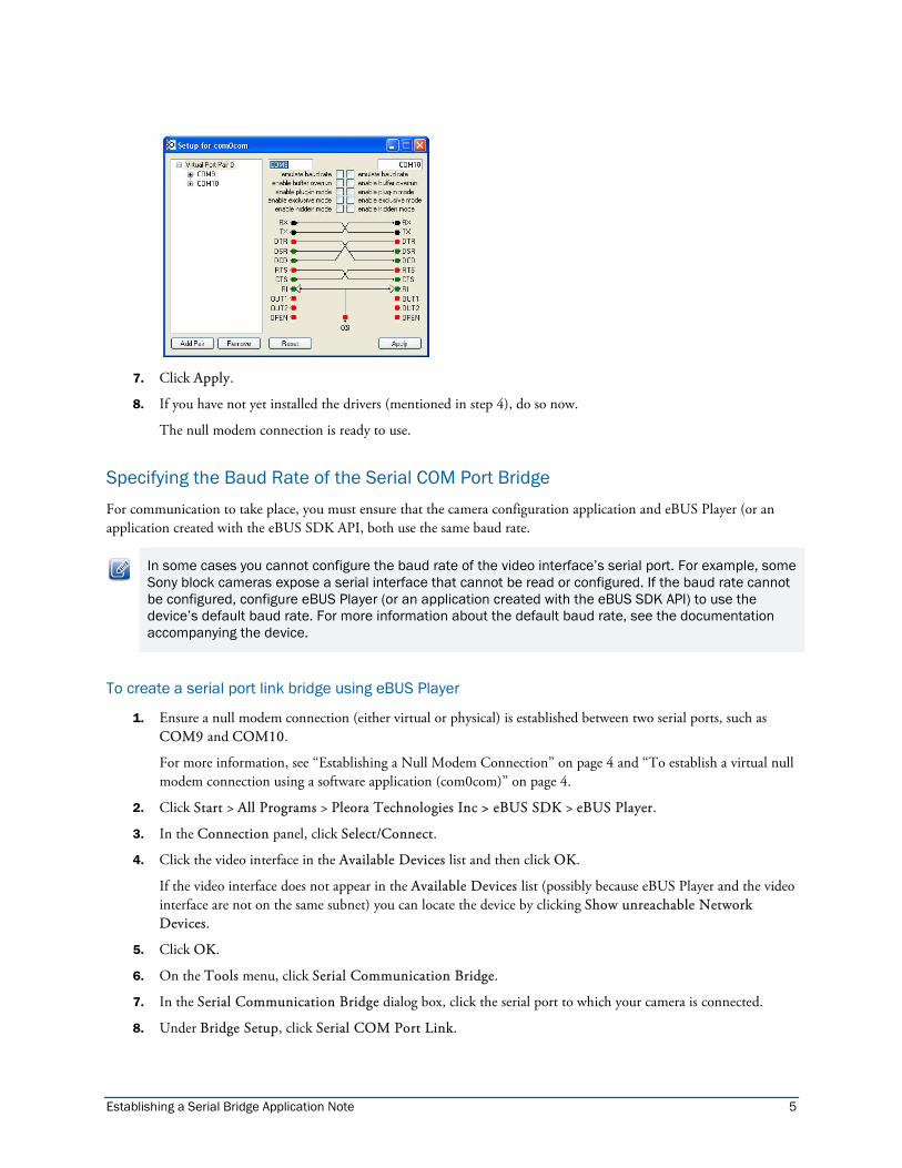
7. Click Apply.
8. If you have not yet installed the drivers (mentioned in step 4), do so now.
The null modem connection is ready to use.
Specifying the Baud Rate of the Serial COM Port Bridge For communication to take place, you must ensure that the camera configuration application and eBUS Player (or an application created with the eBUS SDK API, both use the same baud rate.
In some cases you cannot configure the baud rate of the video interface’s serial port. For example, some Sony block cameras expose a serial interface that cannot be read or configured. If the baud rate cannot be configured, configure eBUS Player (or an application created with the eBUS SDK API) to use the device’s default baud rate. For more information about the default baud rate, see the documentation accompanying the device.
To create a serial port link bridge using eBUS Player
1. Ensure a null modem connection (either virtual or physical) is established between two serial ports, such as COM9 and COM10.
For more information, see ‘‘Establishing a Null Modem Connection’’ on page 4 and ‘‘To establish a virtual null modem connection using a software application (com0com)’’ on page 4.
2. Click Start > All Programs > Pleora Technologies Inc > eBUS SDK > eBUS Player.
3. In the Connection panel, click Select/Connect.
4. Click the video interface in the Available Devices list and then click OK.
If the video interface does not appear in the Available Devices list (possibly because eBUS Player and the video interface are not on the same subnet) you can locate the device by clicking Show unreachable Network Devices.
5. Click OK.
6. On the Tools menu, click Serial Communication Bridge.
7. In the Serial Communication Bridge dialog box, click the serial port to which your camera is connected.
8. Under Bridge Setup, click Serial COM Port Link.

Establishing a Serial Bridge Application Note 6
9. In the Port list, click one of the null modem COM ports, such as COM9.
10. Review the settings that appear below the Port list. These settings must match the port settings configured in the camera configuration application. If the settings do not match, click Configure and change the serial port configuration. In eBUS Player, only the available baud rates can be selected; the currently selected baud rate appears in bold.
Note: For guidance on selecting the baud rate, see ‘‘Specifying the Baud Rate of the Serial COM Port Bridge’’ on page 5.
The serial port link bridge is ready to use.
11. Start the camera configuration application.
12. Select the other serial port of the null modem connection, such as COM10.
13. Ensure that the serial port configuration matches the eBUS Player serial port configuration, as mentioned in step 9.
14. Configure your camera as required, using the camera configuration application started in step 11.
15. In the eBUS Player Serial Communication Bridge dialog box, review the information under Statistics to confirm that data is being sent from the camera configuration application.
Establishing a Serial Bridge Application Note 7
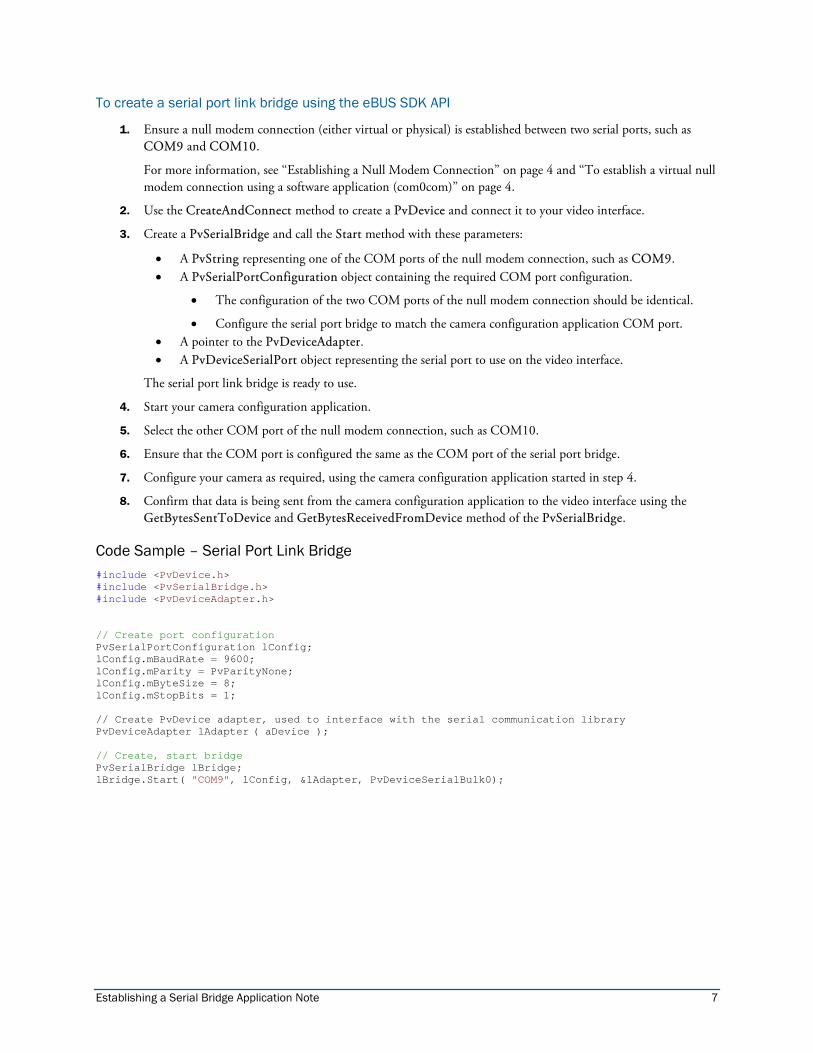
To create a serial port link bridge using the eBUS SDK API
1. Ensure a null modem connection (either virtual or physical) is established between two serial ports, such as COM9 and COM10.
For more information, see ‘‘Establishing a Null Modem Connection’’ on page 4 and ‘‘To establish a virtual null modem connection using a software application (com0com)’’ on page 4.
2. Use the CreateAndConnect method to create a PvDevice and connect it to your video interface.
3. Create a PvSerialBridge and call the Start method with these parameters:
• A PvString representing one of the COM ports of the null modem connection, such as COM9. • A PvSerialPortConfiguration object containing the required COM port configuration.
• The configuration of the two COM ports of the null modem connection should be identical.
• Configure the serial port bridge to match the camera configuration application COM port. • A pointer to the PvDeviceAdapter. • A PvDeviceSerialPort object representing the serial port to use on the video interface.
The serial port link bridge is ready to use.
4. Start your camera configuration application.
5. Select the other COM port of the null modem connection, such as COM10.
6. Ensure that the COM port is configured the same as the COM port of the serial port bridge.
7. Configure your camera as required, using the camera configuration application started in step 4.
8. Confirm that data is being sent from the camera configuration application to the video interface using the GetBytesSentToDevice and GetBytesReceivedFromDevice method of the PvSerialBridge.
Code Sample – Serial Port Link Bridge #include <PvDevice.h> #include <PvSerialBridge.h> #include <PvDeviceAdapter.h> // Create port configuration PvSerialPortConfiguration lConfig; lConfig.mBaudRate = 9600; lConfig.mParity = PvParityNone; lConfig.mByteSize = 8; lConfig.mStopBits = 1; // Create PvDevice adapter, used to interface with the serial communication library PvDeviceAdapter lAdapter ( aDevice ); // Create, start bridge PvSerialBridge lBridge; lBridge.Start( "COM9", lConfig, &lAdapter, PvDeviceSerialBulk0);

Establishing a Serial Bridge Application Note 8
Option 2: Pleora Camera Link DLL
The Camera Link DLL option allows you to use the Pleora Camera Link DLL to establish a connection between the camera configuration application and a Camera Link camera (which is connected to a video interface’s serial port).
Figure 2: Pleora Camera Link DLL
Establishing a Serial Bridge Application Note 9
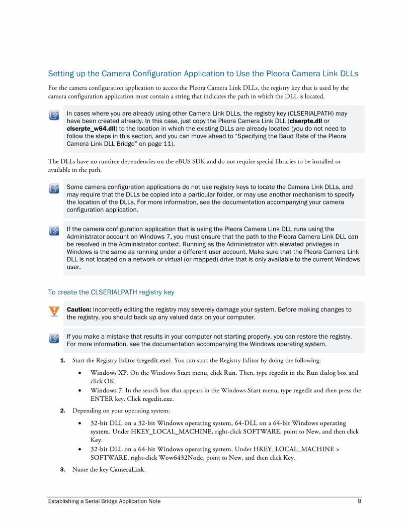
Setting up the Camera Configuration Application to Use the Pleora Camera Link DLLs For the camera configuration application to access the Pleora Camera Link DLLs, the registry key that is used by the camera configuration application must contain a string that indicates the path in which the DLL is located.
In cases where you are already using other Camera Link DLLs, the registry key (CLSERIALPATH) may have been created already. In this case, just copy the Pleora Camera Link DLL (clserpte.dll or clserpte_w64.dll) to the location in which the existing DLLs are already located (you do not need to follow the steps in this section, and you can move ahead to “Specifying the Baud Rate of the Pleora Camera Link DLL Bridge” on page 11).
The DLLs have no runtime dependencies on the eBUS SDK and do not require special libraries to be installed or available in the path.
Some camera configuration applications do not use registry keys to locate the Camera Link DLLs, and may require that the DLLs be copied into a particular folder, or may use another mechanism to specify the location of the DLLs. For more information, see the documentation accompanying your camera configuration application.
If the camera configuration application that is using the Pleora Camera Link DLL runs using the Administrator account on Windows 7, you must ensure that the path to the Pleora Camera Link DLL can be resolved in the Administrator context. Running as the Administrator with elevated privileges in Windows is the same as running under a different user account. Make sure that the Pleora Camera Link DLL is not located on a network or virtual (or mapped) drive that is only available to the current Windows user.
To create the CLSERIALPATH registry key
Caution: Incorrectly editing the registry may severely damage your system. Before making changes to the registry, you should back up any valued data on your computer.
If you make a mistake that results in your computer not starting properly, you can restore the registry. For more information, see the documentation accompanying the Windows operating system.
1. Start the Registry Editor (regedit.exe). You can start the Registry Editor by doing the following:
• Windows XP. On the Windows Start menu, click Run. Then, type regedit in the Run dialog box and click OK.
• Windows 7. In the search box that appears in the Windows Start menu, type regedit and then press the ENTER key. Click regedit.exe.
2. Depending on your operating system:
• 32-bit DLL on a 32-bit Windows operating system, 64-DLL on a 64-bit Windows operating system. Under HKEY_LOCAL_MACHINE, right-click SOFTWARE, point to New, and then click Key.
• 32-bit DLL on a 64-bit Windows operating system. Under HKEY_LOCAL_MACHINE > SOFTWARE, right-click Wow6432Node, point to New, and then click Key.
3. Name the key CameraLink.
Establishing a Serial Bridge Application Note 10
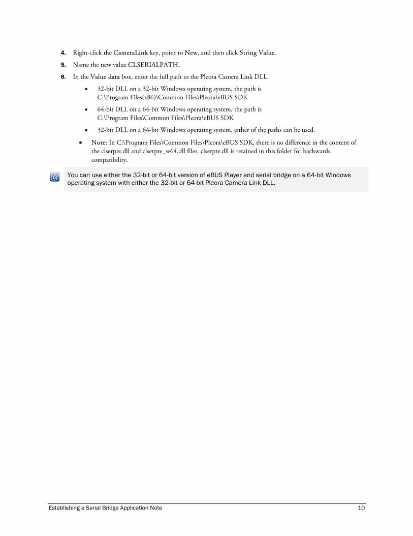
4. Right-click the CameraLink key, point to New, and then click String Value.
5. Name the new value CLSERIALPATH.
6. In the Value data box, enter the full path to the Pleora Camera Link DLL.
• 32-bit DLL on a 32-bit Windows operating system, the path is C:\Program Files(x86)\Common Files\Pleora\eBUS SDK
• 64-bit DLL on a 64-bit Windows operating system, the path is C:\Program Files\Common Files\Pleora\eBUS SDK
• 32-bit DLL on a 64-bit Windows operating system, either of the paths can be used.
• Note: In C:\Program Files\Common Files\Pleora\eBUS SDK, there is no difference in the content of the clserpte.dll and clserpte_w64.dll files. clserpte.dll is retained in this folder for backwards compatibility.
You can use either the 32-bit or 64-bit version of eBUS Player and serial bridge on a 64-bit Windows operating system with either the 32-bit or 64-bit Pleora Camera Link DLL.

Establishing a Serial Bridge Application Note 11
Specifying the Baud Rate of the Pleora Camera Link DLL Bridge The available baud rates for the video interface’s serial port are shown in the Available/Selectable Baud Rates list in the eBUS Player Serial Communication Bridge dialog box.
14400 and 28800 can be supported by the video interface serial port but are not supported by the Camera Link standard --- they are always disabled for a Pleora Camera Link DLL bridge.
If the baud rate of the video interface serial port is not available in the GenICam interface, a dialog box prompts you to provide the hard-coded baud rate in use. You must select the default, unchangeable baud rate used by the serial port.
The application using the Pleora Camera Link DLL controls which of the available video interface serial port baud rates to use. When the application changes the baud rate through the Pleora Camera Link DLL, the bridge updates the configuration of the video interface serial port accordingly.
If the video interface’s GenICam interface does not allow you to control the serial port baud rate, only the hard-coded baud rate (which is provided by the user) is offered as a choice.
For information about changing the application’s baud rate, see the documentation accompanying the application. The procedure for specifying the baud rate varies, depending on the application (for example, it may be specified before connecting, automatically negotiated, only possible when connected to the camera, and so on).
To start the Pleora Camera Link DLL bridge using eBUS Player
1. Ensure the eBUS SDK Camera Link DLL (clserpte.dll or clserpte_w64.dll) is available and its path is in the registry.
For more information, see ‘‘Setting up the Camera Configuration Application to Use the Pleora Camera Link DLL’’ on page 9.
2. Click Start > All Programs > Pleora Technologies Inc > eBUS SDK > eBUS Player.
3. In the Connection panel, click Select/Connect.
4. Click the video interface in the Available Devices list and then click OK.
If the video interface does not appear in the Available Devices list (possibly because eBUS Player and the video interface are not on the same subnet) you can locate the device by clicking Show unreachable Network Devices.
5. Click OK.
6. On the Tools menu, click Serial Communication Bridge.
7. In the Serial Communication Bridge dialog box, click the serial port to which your camera is connected.
8. Under Bridge Setup, click Camera Link DLL.
Note the Camera Link DLL port name. It should contain the device MAC address and video interface port name.
In the following example, 00:11:22:33:44::55-Bulk0 is the automatically-generated port name.

Establishing a Serial Bridge Application Note 12
The Pleora Camera Link DLL bridge is ready to use.
9. Start your camera configuration application.
10. Select the Pleora Camera Link DLL port you created when you started the bridge.
In the example above, the port is 00:11:22:33:44::55-Bulk0.
11. If prompted, select the only available baud rate.
12. Configure your camera as required, using the camera configuration application started in step 9.
13. In the eBUS Player Serial Communication Bridge dialog box, review the information under Statistics to confirm that data is being sent from the camera configuration application to the video interface.
To start the Pleora Camera Link DLL bridge using the eBUS SDK API
1. Ensure the eBUS SDK Camera Link DLL (clserpte.dll or clserpte_w64.dll) is available and its path is in the registry.
For more information, see ‘‘Setting up the Camera Configuration Application to Use the Pleora Camera Link DLL’’ on page 9.
2. Use the CreateAndConnect method to create a PvDevice and connect it to your video interface.
3. Create a PvSerialBridge object.
• Call the Start method with these parameters:
• Pleora Camera Link DLL port name, such as MyBridge. • A pointer to the PvDeviceAdapter. • A PvDeviceSerialPort object that refers to the serial port to use on the video interface.
• If the baud rate of the video interface serial port cannot be configured using the GenICam interface of the video interface, specify the hard-coded serial port baud rate using the PvSerialBridge::SetHardCodedBaudRate method.

Establishing a Serial Bridge Application Note 13
The Pleora Camera Link DLL bridge is ready to use.
4. Start your camera configuration application.
5. Select the Pleora Camera Link DLL port that you just created, such as Pleora#MyBridge.
6. If prompted, select the only available speed.
7. Configure your camera as required, using the camera configuration application started in step 4.
8. Use the GetBytesSentToDevice and GetBytesReceivedFromDevice methods of the PvSerialBridge to confirm that data is flowing.
Code Sample – Pleora Camera Link DLL Bridge #include <PvDevice.h> #include <PvSerialBridge.h> #include <PvDeviceAdapter.h> // Create PvDevice adapter, used to interface the serial communication library PvDeviceAdapter lAdapter ( aDevice ); // Create, start bridge PvSerialBridge lBridge; lBridge.Start( "MyBridge", &ladapter, PvDeviceSerialBulk0 );
Option 3: GenICam CLProtocol
Instead of using a camera configuration application, the GenICam CLProtocol allows you to control camera parameters through a GenICam interface, such as eBUS Player or your own eBUS SDK application.
The CLProtocol DLL allows communication between the GenICam interface (register-based) and the camera (serial protocol).
CLProtocol DLLs are not provided with the eBUS SDK. CLProtocol DLLs can be camera-specific, family-specific, or vendor-specific. Because CLProtocol DLLs are not mandatory (according to the Camera Link standard), some camera manufacturers may not provide them.
The eBUS SDK builds the GenICam interface from a GenICam XML file that is provided by the CLProtocol DLL. How the XML file is provided varies, depending on the camera manufacturer: for example, the XML file can be retrieved from the camera, bundled in the CLProtocol DLL, or it can be deployed as a file next to the CLProtocol DLL.
The link between the CL Protocol library and the eBUS SDK’s serial bridge is the eBUS SDK’s Camera Link DLL, clserpte.dll, as described in ‘‘Option 2: Pleora Camera Link DLL’’ on page 8.

Establishing a Serial Bridge Application Note 14
Figure 3: GenICam CLProtocol
Installing a GenICam CLProtocol DLL The GenICam CL Protocol relies on the eBUS SDK Camera Link DLL. It needs to be available and properly registered (CLSERIALPATH registry key) as outlined in ‘‘Setting up the Camera Configuration Application to Use the Pleora Camera Link DLL’’ on page 9.
An environment variable called GENICAM_CLPROTOCOL contains a list of all paths on the system where a CLProtocol DLL can be found. Just like the system PATH environment variable, if more than one path is defined, the paths are separated by semicolons.
The paths point to a folder where CLProtocol DLLs are located, within platform-specific folders: Win32_i86 for 32-bit applications and Win64_x64 for 64-bit applications. 32-bit applications (Windows 32 or 64-bit) require a 32-bit CLProtocol DLL and 64-bit applications (Windows 64-bit only) require a 64-bit CLProtocol DLL.
You should place CLProtocol DLLs from different camera manufacturers in different folders on your computer, and you should define their paths in the GENICAM_CLPROTOCOL environment variable.
Using a Software Installer to Automatically Define the Environment Variable
Some camera manufacturers may provide a software installer that deploys tools, documentation, and a CLProtocol library for the camera. If this has been provided, the software installer typically defines or extends the GENICAM_CLPROTOCOL environment variable during installation.
We recommend that you verify that the CLProtocol DLL installation completed properly. Navigate to the installation folder and locate the CLProtocol path (for example, C:\Program Files\CameraManufacturerName or C:\Program Files (x86)\ CameraManufacturerName). Then, verify that the GENICAM_CLPROTOCOL environment variable is defined with the correct path.
Manually Defining the Environment Variable
If your camera manufacturer provided you with files (not a software installer) for its CLProtocol solution, follow these steps to manually define the environment variable with the location of the CLProtocol DLL file.
Establishing a Serial Bridge Application Note 15
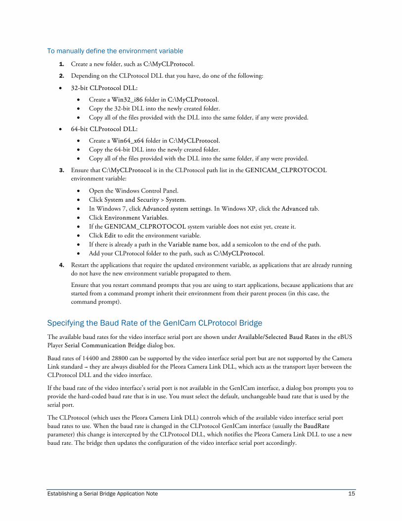
To manually define the environment variable
1. Create a new folder, such as C:\MyCLProtocol.
2. Depending on the CLProtocol DLL that you have, do one of the following:
• 32-bit CLProtocol DLL:
• Create a Win32_i86 folder in C:\MyCLProtocol. • Copy the 32-bit DLL into the newly created folder. • Copy all of the files provided with the DLL into the same folder, if any were provided.
• 64-bit CLProtocol DLL:
• Create a Win64_x64 folder in C:\MyCLProtocol. • Copy the 64-bit DLL into the newly created folder. • Copy all of the files provided with the DLL into the same folder, if any were provided.
3. Ensure that C:\MyCLProtocol is in the CLProtocol path list in the GENICAM_CLPROTOCOL environment variable:
• Open the Windows Control Panel. • Click System and Security > System. • In Windows 7, click Advanced system settings. In Windows XP, click the Advanced tab. • Click Environment Variables. • If the GENICAM_CLPROTOCOL system variable does not exist yet, create it. • Click Edit to edit the environment variable. • If there is already a path in the Variable name box, add a semicolon to the end of the path. • Add your CLProtocol folder to the path, such as C:\MyCLProtocol.
4. Restart the applications that require the updated environment variable, as applications that are already running do not have the new environment variable propagated to them.
Ensure that you restart command prompts that you are using to start applications, because applications that are started from a command prompt inherit their environment from their parent process (in this case, the command prompt).
Specifying the Baud Rate of the GenICam CLProtocol Bridge The available baud rates for the video interface serial port are shown under Available/Selected Baud Rates in the eBUS Player Serial Communication Bridge dialog box.
Baud rates of 14400 and 28800 can be supported by the video interface serial port but are not supported by the Camera Link standard --- they are always disabled for the Pleora Camera Link DLL, which acts as the transport layer between the CLProtocol DLL and the video interface.
If the baud rate of the video interface’s serial port is not available in the GenICam interface, a dialog box prompts you to provide the hard-coded baud rate that is in use. You must select the default, unchangeable baud rate that is used by the serial port.
The CLProtocol (which uses the Pleora Camera Link DLL) controls which of the available video interface serial port baud rates to use. When the baud rate is changed in the CLProtocol GenICam interface (usually the BaudRate parameter) this change is intercepted by the CLProtocol DLL, which notifies the Pleora Camera Link DLL to use a new baud rate. The bridge then updates the configuration of the video interface serial port accordingly.
Establishing a Serial Bridge Application Note 16
If the GenICam interface of the video interface does not allow you to control the baud rate of the serial port, only the hard-coded baud rate provided by the user is offered as a choice to the CLProtocol DLL using the Pleora Camera Link DLL.
Some CLProtocol DLLs may detect and optimize the baud rate on connection. If not, the baud rate can be changed through the BaudRate parameter of the CLProtocol GenICam interface (if supported). To change this, you must first set up the bridge, access the BaudProperty, and then set it to a faster speed, such as 115200 baud.
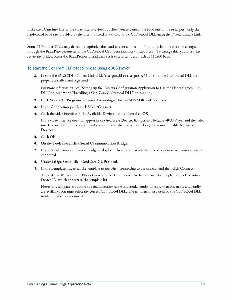
To start the GenICam CLProtocol bridge using eBUS Player
1. Ensure the eBUS SDK Camera Link DLL (clserpte.dll or clserpte_w64.dll) and the CLProtocol DLL are properly installed and registered.
For more information, see ‘‘Setting up the Camera Configuration Application to Use the Pleora Camera Link DLL’’ on page 9 and ‘‘Installing a GenICam CLProtocol DLL’’ on page 14.
2. Click Start > All Programs > Pleora Technologies Inc > eBUS SDK > eBUS Player.
3. In the Connection panel, click Select/Connect.
4. Click the video interface in the Available Devices list and then click OK.
If the video interface does not appear in the Available Devices list (possibly because eBUS Player and the video interface are not on the same subnet) you can locate the device by clicking Show unreachable Network Devices.
5. Click OK.
6. On the Tools menu, click Serial Communication Bridge.
7. In the Serial Communication Bridge dialog box, click the video interface serial port to which your camera is connected.
8. Under Bridge Setup, click GenICam CL Protocol.
9. In the Template list, select the template to use when connecting to the camera, and then click Connect.
The eBUS SDK creates the Pleora Camera Link DLL interface to the camera. The template is resolved into a Device ID, which appears in the template list.
Note: The template is built from a manufacturer name and model family. If more than one name and family are available, you must select the correct CLProtocol DLL. The template is also used by the CLProtocol DLL to identify the camera model.
Establishing a Serial Bridge Application Note 17
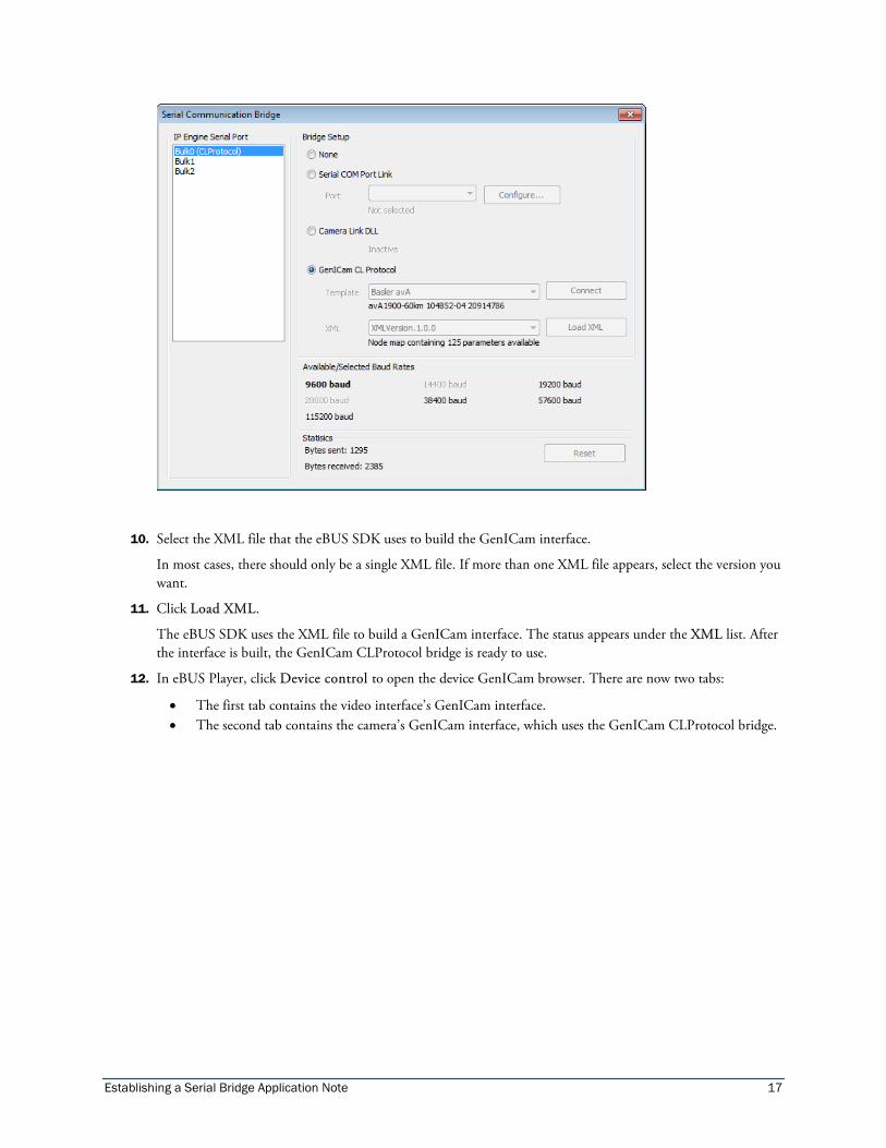
10. Select the XML file that the eBUS SDK uses to build the GenICam interface.
In most cases, there should only be a single XML file. If more than one XML file appears, select the version you want.
11. Click Load XML.
The eBUS SDK uses the XML file to build a GenICam interface. The status appears under the XML list. After the interface is built, the GenICam CLProtocol bridge is ready to use.
12. In eBUS Player, click Device control to open the device GenICam browser. There are now two tabs:
• The first tab contains the video interface’s GenICam interface. • The second tab contains the camera’s GenICam interface, which uses the GenICam CLProtocol bridge.
Establishing a Serial Bridge Application Note 18
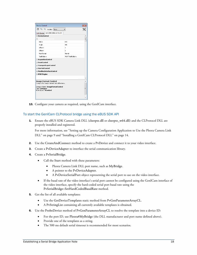
13. Configure your camera as required, using the GenICam interface.
To start the GenICam CLProtocol bridge using the eBUS SDK API
1. Ensure the eBUS SDK Camera Link DLL (clserpte.dll or clserpte_w64.dll) and the CLProtocol DLL are properly installed and registered.
For more information, see ‘‘Setting up the Camera Configuration Application to Use the Pleora Camera Link DLL’’ on page 9 and ‘‘Installing a GenICam CLProtocol DLL’’ on page 14.
2. Use the CreateAndConnect method to create a PvDevice and connect it to your video interface.
3. Create a PvDeviceAdapter to interface the serial communication library.
4. Create a PvSerialBridge.
• Call the Start method with these parameters:
• Pleora Camera Link DLL port name, such as MyBridge. • A pointer to the PvDeviceAdapter. • A PvDeviceSerialPort object representing the serial port to use on the video interface.
• If the baud rate of the video interface’s serial port cannot be configured using the GenICam interface of the video interface, specify the hard-coded serial port baud rate using the PvSerialBridge::SetHardCodedBaudRate method.
5. Get the list of all available templates:
• Use the GetDeviceTemplates static method from PvGenParameterArrayCL. • A PvStringList containing all currently available templates is obtained.
6. Use the ProbeDevice method of PvGenParameterArrayCL to resolve the template into a device ID:
• For the port ID, use Pleora#MyBridge (the DLL manufacturer and port name defined above). • Provide one of the templates as a string. • The 500 ms default serial timeout is recommended for most scenarios.
Establishing a Serial Bridge Application Note 19
7. Instantiate and connect the PvGenParameterArrayCL:
• For the port ID, use Pleora#MyBridge (the DLL manufacturer name and port name defined above). • For the Device ID, use the Device ID obtained from the ProbeDevice operation.
8. Retrieve the list of available XML IDs:
• Use GetXMLIDs from the connected PvGenParameterArrayCL object. • A PvStringList containing all the currently available XML IDs is returned.
9. Build the node map:
• Provide the selected XML ID as a string.
10. Begin using the CLProtocol GenICam interface:
• It is used just like a regular PvGenParameterArray. • Enumerate parameters with GetCount and GetParameter. • Access parameters with SetIntegerValue, GetIntegerValue, GetFloatValue, SetFloatValue, and so on. • This can be used with the eBUS SDK’s GenICam browser, PvGenBrowserWnd.
Code Sample – GenICam CLProtocol Bridge #include <PvDevice.h> #include <PvSerialBridge.h> #include <PvGenParameterArrayCL.h> #include <PvDeviceAdapter.h> // Create PvDevice adapter, used to interface the serial communication library PvDeviceAdapter lAdapter ( aDevice ); // Create, start bridge PvSerialBridge lBridge; lBridge.Start( "MyBridge", &lAdapter, PvDeviceSerialBulk0 ); // Retrieve available templates PvStringList lTemplateList; PvGenParameterArrayCL::GetDeviceTemplates( lTemplateList ); // Transform the template (assume first of the list) in device ID PvString lDeviceID = PvGenParameterArrayCL::ProbeDevice( "Pleora#MyBridge", *lTemplateList[ 0 ] ); // Instantiate PvGenParameterArrayCL object PvGenParameterArrayCL lArray; // Connect the PvGenParameterArrayCL lArray.Connect( "Pleora#MyBridge", lDeviceID ); // Retrieve available XML IDs PvStringList lXMLIDsList; lArray.GetXMLIDs( lXMLIDsList ); // Build the node map (assume first XML ID is what we want) lArray.Build( *lXMLIDsList[ 0 ] );
Establishing a Serial Bridge Application Note 20
Copyright Information
Copyright © 2015 Pleora Technologies Inc.
These products are not intended for use in life support appliances, devices, or systems where malfunction of these products can reasonably be expected to result in personal injury. Pleora Technologies Inc. (Pleora) customers using or selling these products for use in such applications do so at their own risk and agree to indemnify Pleora for any damages resulting from such improper use or sale.
Trademarks
PureGEV, eBUS, iPORT, vDisplay, and all product logos are trademarks of Pleora Technologies. Third party copyrights and trademarks are the property of their respective owners.
Notice of Rights
All information provided in this manual is believed to be accurate and reliable. No responsibility is assumed by Pleora for its use. Pleora reserves the right to make changes to this information without notice. Redistribution of this manual in whole or in part, by any means, is prohibited without obtaining prior permission from Pleora.
Document Number
EX003-017-0004 Version 2.0