esid 03-06 installation manual v1.0 · esid 03-06 installation manual version: 1.0 introduction the...
TRANSCRIPT

www.esid.se Page:
1 / 20
Name of document:
eSID 03-06 Installation Manual Version:
1.0
eSID 03-06
Installation Manual
extended Saab Information Display (eSID)
for new generation Saab 9-3 (MY2003-2006)
with HPD (High Position Display)

www.esid.se Page:
2 / 20
Name of document:
eSID 03-06 Installation Manual Version:
1.0
Introduction ...................................................................................................................... 3
eSID 03-06 components ..................................................................................................... 5
eSID-HPD .................................................................................................................................. 5
eSID-GW ................................................................................................................................... 5
System Overview .............................................................................................................. 6
Electrical Architecture with eSID 03-06 ...................................................................................... 6
Schematic eSID 03-06................................................................................................................ 7
Installation ....................................................................................................................... 8

www.esid.se Page:
3 / 20
Name of document:
eSID 03-06 Installation Manual Version:
1.0
Introduction The eSID2 (extended Saab Information Display) product was released to the market in late 2014 to
give the owners of a new generation Saab 9-3 MY2007 to MY2014 the possibility to use the display in
the instrument cluster to show hidden vehicle data like for instance torque, power, tire pressure,
read fault codes and instantaneous fuel consumption but also non-display related functions like
”Three-Blink” if the driver touches the turn indicator stalk while changing lanes or a manual
selectable wiper arm speed.
However based on market response, there was also a need for an eSID for the customers of the first
model years of the new generation Saab 9-3 (2003-2006), and the answer is eSID 03-06!
The early NG9-3 vehicle (2003-2006) is equipped with two CAN-communication buses (P-bus, and I-
bus) and one fiber optic bus (O-bus) as illustrated in the figure below:
Saab 9-3 Electrical Architecture (2003-2006)

www.esid.se Page:
4 / 20
Name of document:
eSID 03-06 Installation Manual Version:
1.0
The ICM exist in three-different levels:
• ICM1 – No Display
• ICM2 – Monographic Display
• ICM3 – LCD Display
The figure below shows how these three components look like (vehicle in figure equipped with
ICM3):
Components related to the SID
The ICM unit reads the status of the switches from SIDC (SID Control) and controls the output to the
SID (marked yellow in Figure 1).
SIDC
SID
ICM3

www.esid.se Page:
5 / 20
Name of document:
eSID 03-06 Installation Manual Version:
1.0
eSID 03-06 components
The eSID 03-06 consists of two components: eSID-HPD that mainly controls the display and eSID-GW
that is a data collection and pre-processing unit.
eSID-HPD
HPD is short for “High Position Display” and was the internal development name of the display
located near the windscreen on these model years (commonly known as SID, Saab Information
Display).
eSID-HPD needs to be installed behind the SID, in series with the display cables between ICM and
SID. This operation also requires that four new cables are installed in the vehicle (more information
later in this document).
eSID-HPD has two connectors, one VEHICLE-connector that is for the original SID connector (with
extra cables) and one DISPLAY-connector where a small adapter cable is installed to the SID.
eSID-HPD
eSID-GW
eSID-GW (Gateway), needs to be placed in the diagnostic connector under the steering wheel above
the driver feet. eSID-GW is easily installed within a few seconds.
eSID-GW

www.esid.se Page:
6 / 20
Name of document:
eSID 03-06 Installation Manual Version:
1.0
System Overview
Electrical Architecture with eSID 03-06
Saab 9-3 Electrical Architecture (2003-2006) with eSID 03-06

www.esid.se Page:
7 / 20
Name of document:
eSID 03-06 Installation Manual Version:
1.0
Schematic eSID 03-06
SID
10
9
3
5
2
6
+30
GND
ALARM
SIDC
1
2
3
4
5
6
7
8
9
10
AOS
(US/CA)
ICM
X1-11
X1-12
X1-13
X1-14
X1-15
X1-16
X1-17
X1-7
X1-8
X1-9
SIDC
1
2
3
4
5
6
7
8
9
10
AOS
(US/CA)
ICM
X1-11
X1-12
X1-13
X1-14
X1-15
X1-16
X1-17
X1-7
X1-8
X1-9 eSID
HPD
V-10
V-9
V-3
V-5
V-2
V-6
V-1
+30
GND
ALARM
CAN
SID
DISPLAY
V-11
V-12
V-4
Electrical Schematic ICM/SID/SIDC/eSID-HPD
eSID-HPD Installed
Original

www.esid.se Page:
8 / 20
Name of document:
eSID 03-06 Installation Manual Version:
1.0
Installation It is recommended to look in the Saab Workshop Instruction System (WIS) when performing some of
these steps.
Step 1) Remove the center ventilation (see WIS) or YouTube:
https://www.youtube.com/watch?v=9jR4k2kOQ6Q
Step 2) Remove ICM (two screws and remove the rear connector)

www.esid.se Page:
9 / 20
Name of document:
eSID 03-06 Installation Manual Version:
1.0
Step 3) Remove the center speaker grille

www.esid.se Page:
10 / 20
Name of document:
eSID 03-06 Installation Manual Version:
1.0
Step 4) Remove the SID
(Two screws, and two connectors in the back)

www.esid.se Page:
11 / 20
Name of document:
eSID 03-06 Installation Manual Version:
1.0
Step 5) Drill a hole from the SID basket to place four new cables to be installed
(Ensure that the drill does not hit the air channels below, look with a lamp into the
instrument panel. It is recommended to use at least 4.5mm drill to fit all the cables and to
drill slightly forward in the direction of the steering wheel for easier installation)
Note! The drilling will be through two layers.

www.esid.se Page:
12 / 20
Name of document:
eSID 03-06 Installation Manual Version:
1.0
Step 6) Push all four cables through the hole (terminals shall be on SID side)
Step 7) Remove the connector housing to the SID (will be used later for adapter cable between
eSID and SID. It’s a tricky connector (crap design actually). The inside part needs to be
slided out and there are two small hooks that holds it in place, one on each side

www.esid.se Page:
13 / 20
Name of document:
eSID 03-06 Installation Manual Version:
1.0
Step 8) Remove the SIDC from the Instrument Panel
(Press together the lock from the back and pushed forward)
Step 9) Push the four cables into the eSID/SID connector:
eSID Pin Cable Colour Cable description
Pin 1 Green ICM – LS CAN
Pin 4 Pink SIDC - Switch PWM
Pin 11 Green/Grey SIDC - Switch Encoder 1
Pin 12 Brown/Orange SIDC - Switch Encoder 2

www.esid.se Page:
14 / 20
Name of document:
eSID 03-06 Installation Manual Version:
1.0
Step 10) Use a cutter and cut off one edge from the SID connector as the figure below shows. This
is needed when connecting it to eSID-HPD.

www.esid.se Page:
15 / 20
Name of document:
eSID 03-06 Installation Manual Version:
1.0
Step 11) Splice three of the new cables from eSID with the cables from the SIDC connector.
SIDC
Pin
eSID-HPD
Pin
Cable Color
MY03-05
Cable Color
MY06
New Cables
Cable description
Pin 1 Pin 11 Green/Grey Brown/Green Green/Grey INFO-switch
Encoder 1
Pin 2 Pin 12 Brown/Orange Grey/Blue Brown/Orange INFO-switch
Encoder 2
Pin 4 Pin 4 Pink White Pink SIDC Switch
status (PWM)

www.esid.se Page:
16 / 20
Name of document:
eSID 03-06 Installation Manual Version:
1.0
Step 12) Open the ICM connector by lifting the lock and slide out the part that has only standard
cables (to avoid damages to the fiber-optic cables when splicing)

www.esid.se Page:
17 / 20
Name of document:
eSID 03-06 Installation Manual Version:
1.0
Step 13) Splice the last of the new cables from eSID-HPD with the I-bus cable in the ICM connector.
ICM
Pin
SID/eSID
Pin
Cable Color
MY03-06
New Cable
Cable description
Pin 1 Pin 1 Green Green I-Bus (LSCAN)

www.esid.se Page:
18 / 20
Name of document:
eSID 03-06 Installation Manual Version:
1.0
Step 14) Move the SID connector housing that was removed in the earlier step and attach it to the
short adapter cable that will be placed between eSID-HPD and SID. It shall be put on the
side where the connector is NOT cut.
www.esid.se Page:
19 / 20
Name of document:
eSID 03-06 Installation Manual Version:
1.0
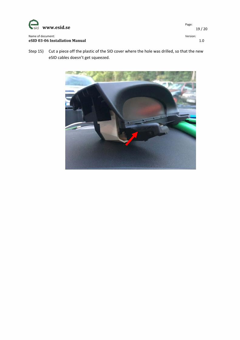
Step 15) Cut a piece off the plastic of the SID cover where the hole was drilled, so that the new
eSID cables doesn’t get squeezed.
www.esid.se Page:
20 / 20
Name of document:
eSID 03-06 Installation Manual Version:
1.0
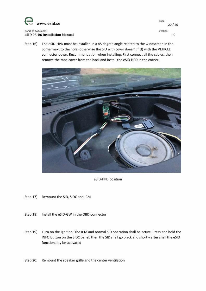
Step 16) The eSID-HPD must be installed in a 45 degree angle related to the windscreen in the
corner next to the hole (otherwise the SID with cover doesn’t fit!) with the VEHICLE
connector down. Recommendation when installing: First connect all the cables, then
remove the tape cover from the back and install the eSID HPD in the corner.
eSID-HPD position
Step 17) Remount the SID, SIDC and ICM
Step 18) Install the eSID-GW in the OBD-connector
Step 19) Turn on the Ignition; The ICM and normal SID operation shall be active. Press and hold the
INFO button on the SIDC panel, then the SID shall go black and shortly after shall the eSID
functionality be activated
Step 20) Remount the speaker grille and the center ventilation