escan user’s guide
TRANSCRIPT

ESCAN User’s Guide

ESCAN USER’S GUIDE Revision 1.02: June 1, 2001 Revision 1.15: July 1, 2002 Revision 1.18 October 1, 2002 Revision 2.02 April 1, 2003 Copyright © 2001 Electrosonic, 2002,2003 MediaSonic All rights reserved No part of this documentation may be reproduced or transmitted in any form or by any means, electronic or mechanical, including photocopying and recording, without the prior written permission of MediaSonic. The information in this documentation is supplied without warranty of any kind, either directly or indirectly, and is subject to change without prior written notice. MediaSonic, its employees or appointed representatives will not be held responsible for any damages to software, hardware, or data, howsoever arising as a direct or indirect result of the product(s) mentioned herein. Issued by: MediaSonic 3420 North San Fernando Blvd., Suite 200 Burbank, CA 91504 Tel: + 1.818.566.3054 Fax: + 1-818-566-3053 E-mail: [email protected] This documentation was written in the United States, England, Hong Kong, India, and Thailand. Printed in the United States. Authored and illustrated by Eric J. Trombley.

ESCAN Preface
Preface
About This User’s Guide
This is a User’s Guide for the ESCAN software application from MediaSonic. The manual is comprised of the following chapters:
Installation: This section walks you through the installation of the ESCAN software.
Chapter 1: Introduction to ESCAN 5.0: This section explains the basic functionality and uses of ESCAN, and familiarizes you with the layout of the software.
Chapter 2: The ESCAN Scheduler: This section explains the functionality of ESCAN’s Scheduler, which is required to run Sequences and Schedules.
Chapter 3: ESCAN System Log: This section explains the functionality of ESCAN’s log window, and how to save log data to a text file.
Chapter 4: Tutorial: The tutorial familiarizes you with the ESCAN workflow by helping you configure two control ports, define two devices, define some simple sequences, and create a basic schedule.
Chapter 5: The Comms Branch: Introduced in the tutorial, this section explains ESCAN’s “Comms” configuration in greater detail.
Chapter 6: The Devices Branch: Introduced in the tutorial, this section explains ESCAN’s “Device” configuration in greater detail.
Chapter 7: The Sequences Branch: Introduced in the tutorial, this section explains how to create ESCAN “Sequences” in greater detail.
Chapter 8: The Schedules Branch: Introduced in the tutorial, this section explains in greater detail how to create “Schedules.”
Chapter 9: The Triggers Branch: This section explains ESCAN’s “Triggers” function.
Chapter 10: The Variables Branch: This section explains how to use variables to control ESCAN functionality.
Chapter 11: MS VideoServer Control: This section explains how to configure and control a MediaSonic VideoServer.
Appendix A: TCP/IP Communications: This section provides an overview of TCP/IP communication for those unfamiliar with the technology.
Appendix B: Time Code Support: This section explains how ESCAN generates and receives time code for precise show control.
Appendix C: ESCAN XML Device Creation: This section explains how to create Device drivers using XML.
Software Versions
The features and functionality described in this User’s Guide are based on ESCAN version 5.0.
i Document Rev. 2.02

ESCAN Preface
Trademarks
ELECTROSONIC® and ES® are registered trademarks of ELECTROSONIC LTD.
MEDIASONIC and the MEDIASONIC® logo are registered trademarks of MEDIASONIC.
WINDOWS® is a registered trademark of MICROSOFT CORPORATION.
PORTSERVER II™ is a trademark of DIGI INTERNATIONAL INCORPORATED.
All other brand and product names are trademarks or registered trademarks of their respective holders.
ii Document Rev. 2.02
ESCAN Table of Contents
Table of Contents
Preface............................................................................................................................................................................................................ i About This User’s Guide................................................................................................................................................................................ i Software Versions .......................................................................................................................................................................................... i Trademarks .................................................................................................................................................................................................... ii
Table of Contents..........................................................................................................................................................................................1
Installation ...................................................................................................................................................................................................11 File Compatibility With ESCAN Version 5.0..............................................................................................................................................11
Show Files ...............................................................................................................................................................................................11 Device Drivers........................................................................................................................................................................................11
ESCAN Functionality Levels.......................................................................................................................................................................11 Installation Overview .................................................................................................................................................................................11 System Requirements.................................................................................................................................................................................11 Installing ESCAN..........................................................................................................................................................................................12
ESCAN Installation.................................................................................................................................................................................12 Gathering and Submitting Registration Information.............................................................................................................................14 Entering the License Key ...........................................................................................................................................................................15
Chapter 1: Introduction to ESCAN 5.0 ......................................................................................................................................................17 File Compatibility With ESCAN Version 5.0..............................................................................................................................................17
Show Files ...............................................................................................................................................................................................17 Device Drivers........................................................................................................................................................................................17
What Is ESCAN? ..........................................................................................................................................................................................17 ESCAN’s Elements ......................................................................................................................................................................................17 Configuring an ESCAN Scheduling System ............................................................................................................................................17 The Main Application Window.................................................................................................................................................................18 Main Menu ..................................................................................................................................................................................................18 Main Toolbar ...............................................................................................................................................................................................19 Window Area ..............................................................................................................................................................................................19 Workspace Tree..........................................................................................................................................................................................19 Viewing and Hiding the Workspace Tree...............................................................................................................................................19
Main Menu.............................................................................................................................................................................................19 Main Tool Bar .........................................................................................................................................................................................19
Log Window ................................................................................................................................................................................................19 Using This Manual .......................................................................................................................................................................................20
Chapter 2: The ESCAN Scheduler .............................................................................................................................................................21 Scheduler Overview ..................................................................................................................................................................................21 Chapter Structure ......................................................................................................................................................................................21 Schedules vs. Scheduler............................................................................................................................................................................21 Scheduler — How To..................................................................................................................................................................................21 Activating the Scheduler ..........................................................................................................................................................................21 Scheduler — Reference ............................................................................................................................................................................22 The ESCAN Configuration Dialog Box .....................................................................................................................................................22 Logging Options Tab .................................................................................................................................................................................22 Log Files Dir Tab ..........................................................................................................................................................................................22 Frame Rate Tab ..........................................................................................................................................................................................22 Licensing Tab ..............................................................................................................................................................................................23 Menu, Main Toolbar, and Keyboard Selections: Scheduler................................................................................................................23
Scheduler Menu Selections.................................................................................................................................................................23 Scheduler Toolbar Buttons...................................................................................................................................................................23 Scheduler Keyboard Hotkeys .............................................................................................................................................................23
Chapter 3: ESCAN System Log ..................................................................................................................................................................25
1 Document Rev. 2.02

ESCAN Table of Contents
ESCAN System Log Overview...................................................................................................................................................................25 System Log Data ........................................................................................................................................................................................25 The Log Window.........................................................................................................................................................................................25 Viewing and Hiding the Log Window .....................................................................................................................................................26
Main Menu.............................................................................................................................................................................................26 Main Tool Bar .........................................................................................................................................................................................26
The Log File..................................................................................................................................................................................................26 Logging Options .........................................................................................................................................................................................26
Accessing the Logging Options .........................................................................................................................................................26 Available Logging Options..................................................................................................................................................................27 Setting the Logging Options ...............................................................................................................................................................27
Log File Location ........................................................................................................................................................................................27 Log File Names............................................................................................................................................................................................28 Log File Data ...............................................................................................................................................................................................28 Viewing the Log Files .................................................................................................................................................................................28 Log File Management ...............................................................................................................................................................................28
Log File Size ............................................................................................................................................................................................28 Creating a Schedule Cue to Manage Log Files ..............................................................................................................................28
Chapter 4: Tutorial ......................................................................................................................................................................................31 Tutorial Overview........................................................................................................................................................................................31
The Tutorial “System” ............................................................................................................................................................................31 Tutorial Goals .........................................................................................................................................................................................31
Creating the Tutorial File ...........................................................................................................................................................................31 Creating a New File ...................................................................................................................................................................................32 Saving the File.............................................................................................................................................................................................32 Defining the System’s Frame Rate...........................................................................................................................................................32
Setting the Frame Rate ........................................................................................................................................................................32 Configuring Communication Ports..........................................................................................................................................................33
Defining the First Com Port ..................................................................................................................................................................33 Defining the Second Com Port ..........................................................................................................................................................34 Opening the Comms Ports ..................................................................................................................................................................34
Adding Devices ..........................................................................................................................................................................................35 Defining the JVC VCR Device ............................................................................................................................................................35 Defining the Extron Switcher Device..................................................................................................................................................36 Checking your work .............................................................................................................................................................................38
Defining Sequences...................................................................................................................................................................................38 Defining the First Sequence ................................................................................................................................................................38 Defining the Second Sequence.........................................................................................................................................................40 Defining the Third Sequence...............................................................................................................................................................42 Defining the Fourth Sequence............................................................................................................................................................42 Checking your work .............................................................................................................................................................................43
Creating a Schedule .................................................................................................................................................................................43 Opening the Daily Schedule...............................................................................................................................................................43 Adding the First Event to the Daily Schedule ...................................................................................................................................44 Adding the Second Event to the Schedule .....................................................................................................................................44 Adding the Third Event to the Schedule ...........................................................................................................................................45 Adding the Fourth Event to the Schedule ........................................................................................................................................45 Checking your Work.............................................................................................................................................................................45
Running the Schedule ...............................................................................................................................................................................46 Running the Schedule..........................................................................................................................................................................46 Stopping the Schedule ........................................................................................................................................................................47
Reviewing Log Activity ..............................................................................................................................................................................47 What You’ve Accomplished ....................................................................................................................................................................48
Chapter 5: The Comms Branch .................................................................................................................................................................49 Comms Overview.......................................................................................................................................................................................49 Chapter Structure ......................................................................................................................................................................................49 Comms — How To......................................................................................................................................................................................49 Accessing The Comms Branch ................................................................................................................................................................49 Configuring Communication Ports..........................................................................................................................................................49
Defining an RS-232 Port ........................................................................................................................................................................49 Defining an Ethernet Port ....................................................................................................................................................................50
2 Document Rev. 2.02
Opening and Closing Comms Ports........................................................................................................................................................51

ESCAN Table of Contents
Opening a Single Comms Port ...........................................................................................................................................................51 Closing a Single Port .............................................................................................................................................................................51 Opening All Comms Ports....................................................................................................................................................................51 Closing All Ports .....................................................................................................................................................................................51 Visual Representation ..........................................................................................................................................................................51
Deleting a Comms Port .............................................................................................................................................................................52 Viewing/Editing a Port’s Properties..........................................................................................................................................................52 Comms — Reference ................................................................................................................................................................................52 The Comms Branch Menu ........................................................................................................................................................................52
Add Comm Port....................................................................................................................................................................................53 Open All Ports ........................................................................................................................................................................................53 Close All Ports ........................................................................................................................................................................................53
The Communication Port Settings Dialog Box .......................................................................................................................................53 The Name Field .....................................................................................................................................................................................53 The RS-232 Region.................................................................................................................................................................................53 TCP/IP Region ........................................................................................................................................................................................54
The Comm Timeouts Dialog Box ..............................................................................................................................................................54 Note ........................................................................................................................................................................................................54
The Comms Port Menu ..............................................................................................................................................................................55 Properties ...............................................................................................................................................................................................55 Delete Comm Port................................................................................................................................................................................55 Open Port...............................................................................................................................................................................................55 Close Port ...............................................................................................................................................................................................56
Comms Icon Representation ...................................................................................................................................................................56
Chapter 6: The Devices Branch.................................................................................................................................................................57 Devices Overview ......................................................................................................................................................................................57 Chapter Structure ......................................................................................................................................................................................57 Devices — How To......................................................................................................................................................................................57 Accessing the Devices Branch ................................................................................................................................................................57 Defining a Device ......................................................................................................................................................................................57 Deleting a Device ......................................................................................................................................................................................58 Viewing/Editing a Device’s Properties....................................................................................................................................................58 Connecting and Disconnecting a Device ............................................................................................................................................58
Connecting a Single Device...............................................................................................................................................................59 Connecting All Devices .......................................................................................................................................................................59 Disconnecting a Single Device ..........................................................................................................................................................59 Disconnecting All Devices...................................................................................................................................................................59 Visual Representation ..........................................................................................................................................................................59
Devices — Reference................................................................................................................................................................................59 The Device Branch Menu .........................................................................................................................................................................59
Add Device ...........................................................................................................................................................................................60 The Add Device Dialog Box......................................................................................................................................................................60 Device Menu ..............................................................................................................................................................................................60
Properties ...............................................................................................................................................................................................61 Delete Device .......................................................................................................................................................................................61 Rename..................................................................................................................................................................................................61 Connect Device ...................................................................................................................................................................................61 Disconnect Device...............................................................................................................................................................................61 Monitor Device Comms.......................................................................................................................................................................61
Scheduler and Variables Devices ...........................................................................................................................................................62 Device Icon Representation.....................................................................................................................................................................62 Menu, Main Toolbar, and Keyboard Selections....................................................................................................................................63
Menu Selections....................................................................................................................................................................................63 Toolbar Buttons......................................................................................................................................................................................63 Keyboard Hotkeys ................................................................................................................................................................................63
Chapter 7: The Sequences Branch ...........................................................................................................................................................65 Sequences Overview ................................................................................................................................................................................65 Chapter Structure ......................................................................................................................................................................................65 Sequences — How To................................................................................................................................................................................65 Accessing the Sequences Branch...........................................................................................................................................................65 Creating a Sequence................................................................................................................................................................................65
3 Document Rev. 2.02
Copying a Sequence................................................................................................................................................................................66

ESCAN Table of Contents
Viewing/Editing a Sequence ...................................................................................................................................................................67 Deleting a Sequence ................................................................................................................................................................................67 Deleting a Cue in a Sequence ................................................................................................................................................................67 Manually Running a Sequence ...............................................................................................................................................................68 Stopping a Sequence ...............................................................................................................................................................................68 Sequences — Reference ..........................................................................................................................................................................69 The Sequences Branch Menu ..................................................................................................................................................................69
Add Sequence......................................................................................................................................................................................69 Create New Sequences Dialog Box........................................................................................................................................................69 The Sequence Window .............................................................................................................................................................................69 The Tool Bar .................................................................................................................................................................................................70 The Run-Time Indicator ..............................................................................................................................................................................70 The Wait-Time Indicator.............................................................................................................................................................................70 The Cue-Status Indicator...........................................................................................................................................................................70 The Cue Area..............................................................................................................................................................................................70
The Cue Number Field .........................................................................................................................................................................71 The Time Type Field...............................................................................................................................................................................71 The Time Field ........................................................................................................................................................................................71 Entering the Time ..................................................................................................................................................................................72 The Device Field....................................................................................................................................................................................72 The Cue Description Field....................................................................................................................................................................72
The Edit Schedule Dialog Box...................................................................................................................................................................73 Sequence Pop-up Menu...........................................................................................................................................................................74
Add Sequence......................................................................................................................................................................................74 Edit Sequence .......................................................................................................................................................................................74 Delete Sequence..................................................................................................................................................................................74 Copy Sequence....................................................................................................................................................................................74 Rename..................................................................................................................................................................................................74 Run Sequence.......................................................................................................................................................................................74 Run Sequence From Pointer................................................................................................................................................................75 Stop Sequence .....................................................................................................................................................................................75
Sequence Cue Menu................................................................................................................................................................................75 Add Cue Before Selected Row ..........................................................................................................................................................75 Add Cue After Selected Row .............................................................................................................................................................76 Set Selected Row As Default ..............................................................................................................................................................76 Delete Selected Cue(s) .......................................................................................................................................................................76 Change Time Type ...............................................................................................................................................................................76 Change Time.........................................................................................................................................................................................76 Change Device ....................................................................................................................................................................................77 Disable /Enable Selected Cue(s) .......................................................................................................................................................77
Autoexec and Startup Sequences..........................................................................................................................................................78 The Startup Sequence..........................................................................................................................................................................78 The Autoexec Sequence.....................................................................................................................................................................78
Sequence Icon Representation...............................................................................................................................................................78 Menu and Keyboard Selections ..............................................................................................................................................................78
Menu Selections....................................................................................................................................................................................78 Keyboard Hotkeys ................................................................................................................................................................................79
Chapter 8: The Schedules Branch.............................................................................................................................................................81 Schedules Overview ..................................................................................................................................................................................81 Schedules and Log Files ............................................................................................................................................................................81
Important! ..............................................................................................................................................................................................81 Schedule Priority .........................................................................................................................................................................................81 Running Individual Schedules ..................................................................................................................................................................81 Chapter Structure ......................................................................................................................................................................................81 Schedules — How To .................................................................................................................................................................................82 Accessing the Schedules Branch ............................................................................................................................................................82 Creating a Schedule .................................................................................................................................................................................82 Copying a Schedule..................................................................................................................................................................................83 Viewing/Editing a Schedule .....................................................................................................................................................................83 Deleting a Schedule ..................................................................................................................................................................................84 Deleting a Cue in a Schedule..................................................................................................................................................................84 Activating the Scheduler ..........................................................................................................................................................................84 Running a Schedule...................................................................................................................................................................................84
4 Document Rev. 2.02
Suspending a Schedule ............................................................................................................................................................................85
ESCAN Table of Contents
Schedules — Reference............................................................................................................................................................................85 The Schedules Branch Menu....................................................................................................................................................................85
Add Schedule .......................................................................................................................................................................................86 The Create Day Schedule Dialog Box ....................................................................................................................................................86 The Schedules Window .............................................................................................................................................................................86 The Tool Bar .................................................................................................................................................................................................87 The Run-Time Indicator ..............................................................................................................................................................................87 The Wait-Time Indicator.............................................................................................................................................................................87 The Cue-Status Indicator...........................................................................................................................................................................87 The Cue Area..............................................................................................................................................................................................87
The Sequence Number Field...............................................................................................................................................................88 The Time Field ........................................................................................................................................................................................88 Entering the Time ..................................................................................................................................................................................88 The Device/Sequence Field................................................................................................................................................................88 The Cue Description Field....................................................................................................................................................................89
Schedule Pop-up Menu ............................................................................................................................................................................89 Add Schedule .......................................................................................................................................................................................89 Edit Schedule.........................................................................................................................................................................................89 Delete Schedule ...................................................................................................................................................................................89 Copy Schedule .....................................................................................................................................................................................90 Run Schedule ........................................................................................................................................................................................90 Suspend Schedule................................................................................................................................................................................90
Schedules Cue Pop-Up Menu..................................................................................................................................................................90 Add Cue Before Selected Row ..........................................................................................................................................................90 Add Cue After Selected Row .............................................................................................................................................................90
Schedules Icon Representation ...............................................................................................................................................................90 Menu and Keyboard Selections: Schedules..........................................................................................................................................91
Menu Selections....................................................................................................................................................................................91 Schedules Keyboard Hotkeys .............................................................................................................................................................91
Chapter 9: The Triggers Branch .................................................................................................................................................................93 Triggers Overview .......................................................................................................................................................................................93 Triggering Devices......................................................................................................................................................................................93 Trigger Groups.............................................................................................................................................................................................93 Triggers to Release Cues ...........................................................................................................................................................................94
Example..................................................................................................................................................................................................94 Chapter Structure ......................................................................................................................................................................................94 Triggers — How To ......................................................................................................................................................................................95 Accessing the Triggers Branch .................................................................................................................................................................95 Adding a Trigger Group ............................................................................................................................................................................95 Viewing/Editing a Trigger Group .............................................................................................................................................................95 Deleting a Trigger Group ..........................................................................................................................................................................96 Adding a Trigger to a Trigger Group.......................................................................................................................................................96 Editing a Trigger in a Trigger Group.........................................................................................................................................................97 Creating a Halt Cue in a Sequence .......................................................................................................................................................97 Triggers — Reference.................................................................................................................................................................................97 The Triggers Branch Menu.........................................................................................................................................................................97
Add Trigger Group................................................................................................................................................................................98 The Add New Trigger Group Dialog Box.................................................................................................................................................98 The Triggers (Trigger Group) Window......................................................................................................................................................98 The Tool Bar .................................................................................................................................................................................................98 The Trigger Area .........................................................................................................................................................................................98
The Device Field....................................................................................................................................................................................99 The Event Field.......................................................................................................................................................................................99 The Triggered Device Field..................................................................................................................................................................99 The Action Field.....................................................................................................................................................................................99
The Add New Trigger/Edit Selected Trigger Dialog Box .......................................................................................................................99 Triggering Device Region..........................................................................................................................................................................99
Device ....................................................................................................................................................................................................99 Trigger .....................................................................................................................................................................................................99
Triggered Device Region ....................................................................................................................................................................... 100 Device ................................................................................................................................................................................................. 100 Action .................................................................................................................................................................................................. 100
Trigger Parameter Mapping .................................................................................................................................................................. 100
5 Document Rev. 2.02
The Trigger Group Pop-Up Menu .......................................................................................................................................................... 100

ESCAN Table of Contents
Edit Trigger Group .............................................................................................................................................................................. 101 Delete Trigger Group......................................................................................................................................................................... 101 Rename............................................................................................................................................................................................... 101
The Trigger Pop-Up Menu....................................................................................................................................................................... 101 Add Row ............................................................................................................................................................................................. 101 Edit Selected Row.............................................................................................................................................................................. 101 Delete Selected Row ........................................................................................................................................................................ 101 Cancel................................................................................................................................................................................................. 102
Menu Selections ...................................................................................................................................................................................... 102 Closing Notes ........................................................................................................................................................................................... 102
Chapter 10: The Variables Branch ..........................................................................................................................................................103 Variables Overview................................................................................................................................................................................. 103 Using Variables......................................................................................................................................................................................... 103
Creating Variable Groups ................................................................................................................................................................ 103 Defining Variables.............................................................................................................................................................................. 103 Setting Variable Values..................................................................................................................................................................... 103 Comparing Variables........................................................................................................................................................................ 103 Using Device Property Variables ..................................................................................................................................................... 104
Chapter Structure ................................................................................................................................................................................... 104 Variables — Tutorials ............................................................................................................................................................................... 104 Variable Tutorial #1: Creating a Loop Counter.................................................................................................................................. 104 Creating a New File ................................................................................................................................................................................ 104 Saving the File.......................................................................................................................................................................................... 104 Setting the System’s Frame Rate .......................................................................................................................................................... 105 Creating a Variable Group ................................................................................................................................................................... 105 Defining a Global Variable.................................................................................................................................................................... 105 Setting the Variable’s Value (“Initializing” the Variable) .................................................................................................................. 106 Comparing the Variable’s Value ......................................................................................................................................................... 108 Creating the Last Cue ............................................................................................................................................................................ 109 Testing the Loop ...................................................................................................................................................................................... 110 What You’ve Learned ............................................................................................................................................................................ 110 Variable Tutorial #2: Device Properties ............................................................................................................................................... 110 Creating a New File. ............................................................................................................................................................................... 110 Saving the File. ......................................................................................................................................................................................... 111 Setting the System’s Frame Rate. ......................................................................................................................................................... 111 Comms Port Definition............................................................................................................................................................................ 111 Device Definition. .................................................................................................................................................................................... 111
Defining the AMX Device ................................................................................................................................................................. 111 Defining the Autopatch Device...................................................................................................................................................... 112
Creating the AMX Handler Sequence................................................................................................................................................. 113 Create the AMX Trigger Group ............................................................................................................................................................ 113
Creating the Trigger Group and Trigger ........................................................................................................................................ 113 About the AMX Trigger...................................................................................................................................................................... 114
Finishing the AMX Handler Sequence.................................................................................................................................................. 114 What You’ve Learned ............................................................................................................................................................................ 117 Variables — How To ................................................................................................................................................................................ 117 Accessing the Variables Branch........................................................................................................................................................... 117 Adding a Variable Group...................................................................................................................................................................... 118 Viewing/Editing a Variable Group ....................................................................................................................................................... 118 Adding a Variable to a Variable Group ............................................................................................................................................. 118 Editing a Variable in a Variable Group ............................................................................................................................................... 119 Variables — Reference .......................................................................................................................................................................... 119 The Variables Branch Menu................................................................................................................................................................... 119
Add Variable Group ......................................................................................................................................................................... 119 The Add New Variable Group Dialog Box .......................................................................................................................................... 119 The Variables (Variable Group) Window ............................................................................................................................................ 120 The Tool Bar .............................................................................................................................................................................................. 120 The Variables Area.................................................................................................................................................................................. 120
The Type Field ..................................................................................................................................................................................... 120 The Variable Name Field .................................................................................................................................................................. 120
The Define Variable Dialog Box ............................................................................................................................................................ 121 The Type Field ..................................................................................................................................................................................... 121 The Name Field .................................................................................................................................................................................. 121
6 Document Rev. 2.02
The Variable Group Pop-Up Menu....................................................................................................................................................... 121
ESCAN Table of Contents
Edit Variable Group........................................................................................................................................................................... 121 Delete Variable Group ..................................................................................................................................................................... 121 Rename............................................................................................................................................................................................... 122
The Variable Pop-Up Menu ................................................................................................................................................................... 122 Add Row ............................................................................................................................................................................................. 122 Edit Selected Row.............................................................................................................................................................................. 122 Delete Selected Row ........................................................................................................................................................................ 122 Cancel................................................................................................................................................................................................. 122
Edit Variables Cue Dialog Box............................................................................................................................................................... 122 Change Tab............................................................................................................................................................................................. 122 The Set Region ......................................................................................................................................................................................... 123
Variable............................................................................................................................................................................................... 123 Device Property ................................................................................................................................................................................. 123
The Operator Selector ............................................................................................................................................................................ 124 The Operand Region .............................................................................................................................................................................. 124
Variable............................................................................................................................................................................................... 124 Device Property ................................................................................................................................................................................. 124 Value.................................................................................................................................................................................................... 124
Test Tab ..................................................................................................................................................................................................... 125 The If Region............................................................................................................................................................................................. 125
Variable............................................................................................................................................................................................... 125 Device Property ................................................................................................................................................................................. 126
The Operator Selector ............................................................................................................................................................................ 126 The Operand Region .............................................................................................................................................................................. 126
Variable............................................................................................................................................................................................... 126 Device Property ................................................................................................................................................................................. 126 Value.................................................................................................................................................................................................... 126
The Device to Control Region............................................................................................................................................................... 127 Device Selector.................................................................................................................................................................................. 127 Device Control Button ...................................................................................................................................................................... 127
Menu Selections ...................................................................................................................................................................................... 127
Chapter 11: VideoServer Control ............................................................................................................................................................129 VideoServer Overview............................................................................................................................................................................ 129 VideoServer Control — Tutorial ............................................................................................................................................................. 129 VideoServer Tutorial ................................................................................................................................................................................ 129 Creating a New File. ............................................................................................................................................................................... 129 Saving the File. ......................................................................................................................................................................................... 130 Setting the System’s Frame Rate. ......................................................................................................................................................... 130 Configuring the VideoServer’s Comms Port. ...................................................................................................................................... 130
Defining the Comms Port ................................................................................................................................................................. 130 Opening the Comms Port ................................................................................................................................................................ 131
Defining the VideoServer Device. ........................................................................................................................................................ 131 Connecting the VideoServer Device ............................................................................................................................................. 132
Creating Play Lists.................................................................................................................................................................................... 133 Creating the First Play List ................................................................................................................................................................. 133 Creating the Second Play List.......................................................................................................................................................... 134
Creating VideoServer Sequences ........................................................................................................................................................ 135 Creating Channel 1’s Sequence .................................................................................................................................................... 136 Creating Channel 2’s Sequence .................................................................................................................................................... 138 Running the Sequences.................................................................................................................................................................... 140
MS VideoServer — Reference ............................................................................................................................................................... 140 Play List Window ...................................................................................................................................................................................... 140
Play List Selector................................................................................................................................................................................. 141 Play List Options Button ..................................................................................................................................................................... 141 Play List Area....................................................................................................................................................................................... 141
Play List Options Menu............................................................................................................................................................................ 141 New Playlist ......................................................................................................................................................................................... 142 Copy Playlist ....................................................................................................................................................................................... 142 Delete Playlist ..................................................................................................................................................................................... 142 Delete All ............................................................................................................................................................................................. 142 Import Playlist...................................................................................................................................................................................... 143 Export Playlist ...................................................................................................................................................................................... 143
Play List Area Menu................................................................................................................................................................................. 143
7 Document Rev. 2.02
Add Clip .............................................................................................................................................................................................. 143

ESCAN Table of Contents
Insert Clip............................................................................................................................................................................................. 143 Edit Clip................................................................................................................................................................................................ 144 Delete Clip .......................................................................................................................................................................................... 144 Delete All Clips ................................................................................................................................................................................... 144
Enter VideoServer Cue Dialog Box ....................................................................................................................................................... 144 The Command Selector ................................................................................................................................................................... 144 The Channel List ................................................................................................................................................................................. 145 The Select All Channels Option ....................................................................................................................................................... 145 The Parameter Field........................................................................................................................................................................... 145
Appendix A: TCP/IP Communication .....................................................................................................................................................147 An Introductory Note.............................................................................................................................................................................. 147 Ethernet Communication ...................................................................................................................................................................... 147
RS-232................................................................................................................................................................................................... 147 Ethernet ............................................................................................................................................................................................... 147
TCP/IP Addressing ................................................................................................................................................................................... 147 Static Assignment............................................................................................................................................................................... 147 Dynamic Assignment ........................................................................................................................................................................ 148
The IP Address .......................................................................................................................................................................................... 148 Network and Host Identifiers ............................................................................................................................................................ 148 Class Names ....................................................................................................................................................................................... 148
Choosing IP Addresses ........................................................................................................................................................................... 148 Connecting to an Existing Network ................................................................................................................................................ 149 Establishing an Independent Network ........................................................................................................................................... 149
The Subnet Mask ..................................................................................................................................................................................... 149 Accessing the PC’s Subnet Mask and IP Address: Win 98 & NT....................................................................................................... 150
Opening the Network Dialog Box: Windows 98, and NT ............................................................................................................. 150 Accessing the IP Address and Subnet Mask: Windows 98 .......................................................................................................... 150 Accessing the IP Address and Subnet Mask: Windows NT.......................................................................................................... 151
Accessing the PC’s Subnet Mask and IP Address: Windows 2000 .................................................................................................. 151 Accessing the LAN Connection Definition .................................................................................................................................... 152 Accessing the TCP/IP Address and Subnet Mask......................................................................................................................... 152
Static IP Addressing: Assigning the PC’s IP Address and Subnet Mask........................................................................................... 154 Setting the Subnet Mask ................................................................................................................................................................... 154 Setting the IP Address........................................................................................................................................................................ 154 Saving the Subnet Mask and IP Address Values........................................................................................................................... 154
Dynamic IP Addressing: Setting the IP Address .................................................................................................................................. 154 Setting the IP Address........................................................................................................................................................................ 154 Saving the Subnet Mask and IP Address Values........................................................................................................................... 154
Pinging a Device ..................................................................................................................................................................................... 154 Performing a Ping .............................................................................................................................................................................. 154 Example 1: A successful Ping ........................................................................................................................................................... 155 Example 2: Unsuccessful Pings......................................................................................................................................................... 155
Appendix B: Time Code Support.............................................................................................................................................................157 ESCAN and Time Code .......................................................................................................................................................................... 157 The PC2005 Card..................................................................................................................................................................................... 157
The ES2005 Time Code Card............................................................................................................................................................ 157 The ES4148 Time Code Cable.......................................................................................................................................................... 157
Configuring the Frame Rate.................................................................................................................................................................. 157 Receiving Time Code ............................................................................................................................................................................. 158 Generating Time Code .......................................................................................................................................................................... 158
Configuring ESCAN to Generate Time Code................................................................................................................................ 158 Stopping Time Code Generation.................................................................................................................................................... 158
Appendix C: ESCAN XML Device Creation............................................................................................................................................161 ESCAN Device Driver Overview ............................................................................................................................................................ 161 Creating Device Drivers ......................................................................................................................................................................... 161
Using the ESCAN DDK........................................................................................................................................................................ 161 Using XML ............................................................................................................................................................................................ 161
File extensions and Locations................................................................................................................................................................ 161 ESCAN DDK Device Drivers............................................................................................................................................................... 161 ESCAN XML Device Drivers............................................................................................................................................................... 161
8 Document Rev. 2.02
ESCAN Table of Contents
Additional Information ...................................................................................................................................................................... 162 Internet Explorer 6.0 ................................................................................................................................................................................ 162 XML Driver Creation ................................................................................................................................................................................ 162
File Authoring...................................................................................................................................................................................... 162 XML Header ........................................................................................................................................................................................ 163 ESCAN Device Section...................................................................................................................................................................... 163 Device Name ..................................................................................................................................................................................... 163 Displayed Device Name .................................................................................................................................................................. 164 Commands Section........................................................................................................................................................................... 164 Device Command............................................................................................................................................................................. 164 Command Name .............................................................................................................................................................................. 164 Command Code............................................................................................................................................................................... 165
Troubleshooting ....................................................................................................................................................................................... 165
Index ..........................................................................................................................................................................................................167
9 Document Rev. 2.02

ESCAN Table of Contents
This page intentionally left blank.
10 Document Rev. 2.02

ESCAN Installation
Installation
File Compatibility With ESCAN Version 5.0
Show Files
Show files created in ESCAN version 4.5 and older are not compatible with this release.
Device Drivers
C++-compiled device drivers created for ESCAN versions 4.5 and older are not compatible with this release.
XML device drivers created for older versions of ESCAN are fully compatible with this release.
ESCAN Functionality Levels
Before installing ESCAN, you should be aware of the functionality level you have purchased. The price of ESCAN varies, based on how many devices you will control; more specifically, it varies based on how many communication ports you will open. The functionality levels are as follows:
ESCAN EL Version: Entry level version of ESCAN, which allows the user to open four communication ports;
ESCAN PL16: (ESCAN EL + additional port licenses) Additional port licenses are available (for an additional charge) to extend the capabilities of ESCAN EL in increments of 16 ports, and can be added at any time;
ESCAN UL version: Unlimited version, which allows the user to open an unlimited number of communication ports.
Note
If you are using MediaSonic’s MS9024 FrEND to add communication ports, additional port licenses are not required; purchasing ESCAN EL is the best option in such an instance.
Installation Overview
The installation process for ESCAN is comprised of four basic steps:
Verifying system requirements Performing the ESCAN software installation Gathering and submitting registration information Entering the License Key
System Requirements The following table shows the system requirements for a fully licensed version of ESCAN:
Operating System Microsoft Windows 98 second edition, NT 4.0 SP6 or higher, Windows 2000, or Windows XP Professional
11 Document Rev. 2.02

ESCAN Installation
System RAM 64 MB minimum, or as required by OS
Hard Drive Space 10 MB free hard disk space for the ESCAN application
Additional storage space is required if using ESCAN’s logging feature
Network Adapter 10Base-T or 100Base-T Ethernet Card
CD-ROM Required for software installation
Display Resolution XGA (Recommended)
Installing ESCAN If you wish to use ESCAN in a fully functioning system, you must register the software. ESCAN will run and perform some limited functions if it is not registered, but you will be unable to connect to your attached Devices or read time code until the registration process is completed.
Note
As with many applications designed for use with Windows NT and Windows 2000, you must have administrative privileges to install ESCAN.
ESCAN Installation
The ESCAN installation CD is equipped with an auto-run feature that should start the installation program. If the installation program does not begin automatically after the CD is inserted, perform steps 1 and 2 below; otherwise, proceed to step 3:
1. Click Start on the Windows taskbar, and select Run from the pop-up menu that appears. The Run dialog box will appear.
2. In the text field, enter the drive letter of the CD-ROM drive containing the ESCAN installation CD, and type the following command:
D:\Setup.exe
Where “D” represents the drive that contains the CD.
Alternatively, you can use the Run dialog box’s Browse function to navigate to the file.
Preparing to Install ESCAN
Click OK; the install application will then open and start the installation process.
3. The first install screen provides some introductory information. When you have finished reading it, click Next.
12 Document Rev. 2.02

ESCAN Installation
Opening Install Screen
4. The second screen sets the destination folder for the application. Choose a folder, and click Next.
5. The third screen lets you choose which ESCAN components you will install. The available options are:
Scheduler (the main ESCAN application) PC2005 Time Code Driver (allows for synchronization to an external time code source when
using an ES2005 ISA card) ESCAN Devices (required to control external devices) User Guide (ESCAN’s user guide) GUI Overlay Samples (sample Visual Basic, HTML, and Power Point files for custom ESCAN
GUI design) XML Device Sample
If you wish to perform a full installation, leave all items checked.
If you do not require all of the listed options, you may choose to deselect some of the features.
Click Next when you have finished selecting your options.
A Complete Installation
An Installation with some items deselected
6. The next screen specifies the workgroup folder where ESCAN will be installed. Clicking Next will accept the displayed values, and begin the installation process.
13 Document Rev. 2.02
7. After the installation process is complete, you will be prompted to reboot your PC. Do this before attempting to run ESCAN.

ESCAN Installation
Gathering and Submitting Registration Information After ESCAN is installed, you will want to open the application and gather the information required to register the software.
To gather the information necessary to register ESCAN, perform the following procedure:
1. Launch ESCAN by clicking Start on the Windows taskbar, and launching the ESCAN application. If ESCAN was installed using the default options, ESCAN can be launched by selecting Programs | ESCAN | ESCANScheduler from the Start menu.
2. Open an existing ESCAN file, or create a new file by clicking on the New File icon.
ESCAN’s New File Button
3. Click on Scheduler | Configuration Options… from the main menu. The ESCAN Configuration dialog box will appear, with the Logging Options tab displayed.
4. Click on the Licensing tab.
ESCAN Configuration License Tab
5. Write down the seven-byte license seed for the functionality level you have purchased
6. Locate the serial number on the ESCAN CD, or as provided by MediaSonic.
7. Visit the online web registration page at:
www.mediasonic.info\medialicense\
14 Document Rev. 2.02
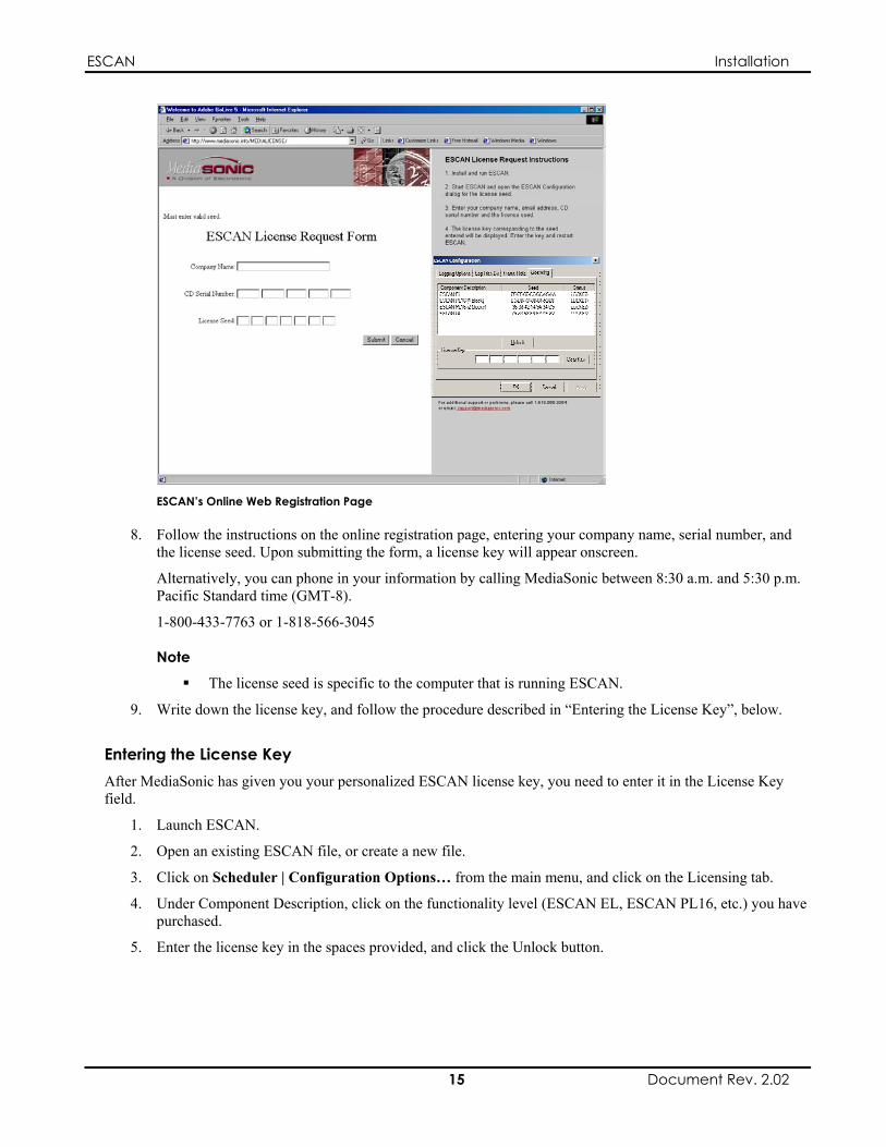
ESCAN Installation
ESCAN’s Online Web Registration Page
8. Follow the instructions on the online registration page, entering your company name, serial number, and the license seed. Upon submitting the form, a license key will appear onscreen.
Alternatively, you can phone in your information by calling MediaSonic between 8:30 a.m. and 5:30 p.m. Pacific Standard time (GMT-8).
1-800-433-7763 or 1-818-566-3045
Note
The license seed is specific to the computer that is running ESCAN.
9. Write down the license key, and follow the procedure described in “Entering the License Key”, below.
Entering the License Key After MediaSonic has given you your personalized ESCAN license key, you need to enter it in the License Key field.
1. Launch ESCAN.
2. Open an existing ESCAN file, or create a new file.
3. Click on Scheduler | Configuration Options… from the main menu, and click on the Licensing tab.
4. Under Component Description, click on the functionality level (ESCAN EL, ESCAN PL16, etc.) you have purchased.
5. Enter the license key in the spaces provided, and click the Unlock button.
15 Document Rev. 2.02

ESCAN Installation
ESCAN Configuration License Tab With License Key Entered
6. Upon successful entry of the license key, a message will appear stating that the ESCAN license is now valid, and that ESCAN must be restarted. Click OK.
License Notice
Note
The licensed (full-function) version of this software may only be installed on one PC. If you replace your network card after registration, you must repeat the information-gathering procedure
described on page 14.
16 Document Rev. 2.02

ESCAN Chapter 1: Introduction to ESCAN
Chapter 1: Introduction to ESCAN 5.0
File Compatibility With ESCAN Version 5.0
Show Files
Show files created in ESCAN version 4.5 and older are not compatible with this release.
Device Drivers
C++-compiled device drivers created for ESCAN versions 4.5 and older are not compatible with this release.
XML device drivers created for older versions of ESCAN are fully compatible with this release.
What Is ESCAN?
ESCAN Scheduler is a Windows-based time-of-day audiovisual control and monitoring system. Designed for continuous, hands-off operation, ESCAN can keep everything from a simple system comprised of a few components to a full museum’s worth of gear running on a daily schedule that includes special-day variations for weekends and holidays.
A useful system-log feature keeps track of every function, external and internal, performed by ESCAN. This provides you with a resource for troubleshooting should any system problems arise.
ESCAN’s Elements
An ESCAN file must contain the following elements:
Comms definitions, which specify the ports that communicate with the attached equipment; Device definitions, which specify the equipment ESCAN is controlling; and Sequences, which hold the commands that tell the attached equipment what functions to perform.
Not required, but present in almost all ESCAN files are:
Schedules, which specify when control commands are sent to the attached equipment.
Two other functions enhance ESCAN’s flexibility, and are sometimes used in more advanced systems:
Triggers, which cause ESCAN to perform functions instigated by external commands sent to the control PC; and
Variables, which process conditional actions when special control functionality is required.
Each of these six elements has a dedicated chapter explaining its functionality, starting with Chapter 5.
Configuring an ESCAN Scheduling System
When authoring an ESCAN file to control your system, the workflow will typically go in this order:
1. Define the system’s frame rate.
2. Define the system’s Comms ports using ESCAN’s Comms branch;
17 Document Rev. 2.02

ESCAN Chapter 1: Introduction to ESCAN
3. Define the equipment in the system using ESCAN’s Devices branch;
4. Set up the commands that will control your equipment and group them as “Sequences” using ESCAN’s Sequences branch.
5. Define the time of day the Sequences will execute using ESCAN’s Schedules branch; and
6. Activate the Scheduler, which will automatically start the appropriate Schedule for the given day.
The tutorial in Chapter 4 walks you through the six steps listed above, and is a great place to start if you have never used ESCAN.
The Main Application Window
The following image shows a typical screen layout for ESCAN:
Log Window
Workspace Tree Main Menu Main Toolbar Window Area
The ESCAN Main Application Window
Main Menu
The main menu provides a selection of drop-down menus, giving access to various functions in ESCAN. Most of the menu functions can also be performed using buttons on various toolbars. Some selections in the main menu are always present, such as File, View, Scheduler, and Help, and some context-based selections appear only when certain windows are open.
18 Document Rev. 2.02

ESCAN Chapter 1: Introduction to ESCAN
Main Toolbar
The main toolbar allows quick access to the most commonly used functions within ESCAN. Most of these functions can also be performed using the menu bar.
Window Area
This area is used to edit Sequences, Schedules, Triggers, and Variables.
Workspace Tree
The Workspace tree provides access to ESCAN’s main elements: Comms ports, Devices, Schedules, Sequences, Triggers, and Variables. You will use the Workspace tree to create and edit these functions.
The Workspace Tree
Viewing and Hiding the Workspace Tree You can open and close the Workspace tree two ways: from the main menu, or from a button on the main tool bar.
Main Menu
Selecting View | Work Space from the main menu will toggle the Workspace window between visible and hidden.
Workspace Option — View Menu
Main Tool Bar
Clicking on the Workspace icon in the main tool bar will toggle the Workspace window between visible and hidden.
Workspace Icon – Main Tool Bar
Log Window
The log window displays a record of system activity. The log feature is explained in detail in Chapter 3, ESCAN System Log.
19 Document Rev. 2.02

ESCAN Chapter 1: Introduction to ESCAN
Using This Manual
It is strongly suggested that you go through the tutorial in Chapter 4, especially if you are unfamiliar with ESCAN. Chapters 5 through 10 detail the main functions of ESCAN, and are a handy reference for those familiar with basic ESCAN operation.
Additional chapters discuss MS VideoServer control, TCP/IP communications, Digi PortServer II setup, ESCAN’s support of Time Code, and creating device drivers using XML.
20 Document Rev. 2.02
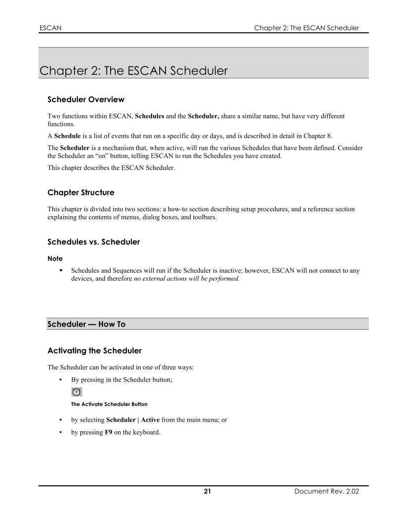
ESCAN Chapter 2: The ESCAN Scheduler
Chapter 2: The ESCAN Scheduler
Scheduler Overview
Two functions within ESCAN, Schedules and the Scheduler, share a similar name, but have very different functions.
A Schedule is a list of events that run on a specific day or days, and is described in detail in Chapter 8.
The Scheduler is a mechanism that, when active, will run the various Schedules that have been defined. Consider the Scheduler an “on” button, telling ESCAN to run the Schedules you have created.
This chapter describes the ESCAN Scheduler.
Chapter Structure
This chapter is divided into two sections: a how-to section describing setup procedures, and a reference section explaining the contents of menus, dialog boxes, and toolbars.
Schedules vs. Scheduler
Note
Schedules and Sequences will run if the Scheduler is inactive; however, ESCAN will not connect to any devices, and therefore no external actions will be performed.
Scheduler — How To
Activating the Scheduler
The Scheduler can be activated in one of three ways:
• By pressing in the Scheduler button;
The Activate Scheduler Button
• by selecting Scheduler | Active from the main menu; or
• by pressing F9 on the keyboard.
21 Document Rev. 2.02
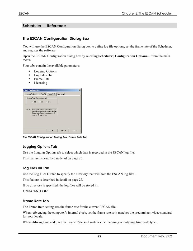
ESCAN Chapter 2: The ESCAN Scheduler
Scheduler — Reference
The ESCAN Configuration Dialog Box
You will use the ESCAN Configuration dialog box to define log file options, set the frame rate of the Scheduler, and register the software.
Open the ESCAN Configuration dialog box by selecting Scheduler | Configuration Options… from the main menu.
Four tabs contain the available parameters:
Logging Options Log Files Dir Frame Rate Licensing
The ESCAN Configuration Dialog Box, Frame Rate Tab
Logging Options Tab Use the Logging Options tab to select which data is recorded in the ESCAN log file.
This feature is described in detail on page 26.
Log Files Dir Tab Use the Log Files Dir tab to specify the directory that will hold the ESCAN log files.
This feature is described in detail on page 27.
If no directory is specified, the log files will be stored in:
C:\ESCAN_LOG\
Frame Rate Tab The Frame Rate setting sets the frame rate for the current ESCAN file.
When referencing the computer’s internal clock, set the frame rate so it matches the predominant video standard for your locale.
When utilizing time code, set the Frame Rate so it matches the incoming or outgoing time code type.
22 Document Rev. 2.02

ESCAN Chapter 2: The ESCAN Scheduler
Note
An ES2005 time code card and ES4148 time code cable are required to read an external time code signal.
Parameter Usage 30 SMPTE time code, frame rate = 30 frames per second. Most commonly
used for lighting and audio control systems. Use this setting for NTSC video rates (29.97 fps) as well.
25 EBU time code, frame rate = 25 frames per second. Used with PAL video formats.
24 Film time code, frame rate = 24 frames per second.
Time code functionality is described in detail in Appendix C, Time Code Support.
Licensing Tab Use the Licensing tab to register your copy of ESCAN. This transforms your copy of ESCAN from an unregistered (edit-only and authoring-only) system, to a registered (edit, author, and control) system.
Refer to the Installation chapter for more information on registering ESCAN.
Menu, Main Toolbar, and Keyboard Selections: Scheduler
Scheduler Menu Selections
Scheduler | Active Toggles the Scheduler between active/not active.
Scheduler | Configuration Options…
Opens the ESCAN Configuration Dialog Box. The ESCAN Configuration dialog box is explained on page 22.
Scheduler | Connect Devices Attempts to connect all attached devices. Only active when Scheduler is running.
Scheduler | Disconnect Devices Disconnects all attached devices. Only active when Scheduler is running.
Scheduler | Reload Schedule Reloads the Schedule, which may be necessary when testing the same Schedule twice in one day.
Scheduler Toolbar Buttons
Activates/Deactivates Scheduler
Attempts to connect all devices; only active when Scheduler is running
Disconnects all devices; only active when Scheduler is running
Reloads the Schedule
Scheduler Keyboard Hotkeys
F9 Activates/Deactivates Scheduler
F11 Attempts to connect all devices
F12 Disconnects all devices
23 Document Rev. 2.02

ESCAN Chapter 2: The ESCAN Scheduler
This page intentionally left blank.
24 Document Rev. 2.02

ESCAN Chapter 3: ESCAN System Log
Chapter 3: ESCAN System Log
ESCAN System Log Overview
ESCAN’s system log records everything that occurs in the Scheduling system. Information such as commands sent to devices, launched events, and warnings are all logged and time stamped in the log file. This information can later be used for troubleshooting purposes if there are problems reported with the system.
Log file data is sent to two places; the log window, where it can be viewed within ESCAN, and to a log file located on the hard drive.
System Log Data
Here are some examples of the information recorded in the log file:
Schedule operational messages, which record what time a Schedule started and what ESCAN file is loaded.
The date and time a given Sequence starts and finishes running. Warning messages. Incoming Triggers. Device conflicts, which prevent preset trigger operation. Commands sent to devices. Error messages. Error messages can be generated from the Scheduler, such as when a day is reached which
does not have a schedule, or from a device driver when failures occur. Device responses. These messages are device driver dependant. An example message would be for a
Media Matrix device to report when a preset has completed.
The Log Window
The log window displays the 1000 most recently recorded log entries. Each entry is recorded with a time and date stamp, as well as a description of the event that occurred.
Date Stamp Time Stamp Message
The Log Window
25 Document Rev. 2.02

ESCAN Chapter 3: ESCAN System Log
Viewing and Hiding the Log Window You can open and close the log window two ways; from the main menu, or from a button on the main tool bar.
Main Menu
Selecting View | Log Window from the main menu will toggle the log window between visible and hidden.
Log Window Option — View Menu
Main Tool Bar
Clicking on the logbook icon in the main tool bar will toggle the Log window between visible and hidden.
Logbook Icon — Main Tool Bar
The Log File
While system log information can be viewed in the log window, log data is also recorded in text files saved on the ESCAN PC’s hard drive. One day’s worth of log data is recorded per text file. This allows for the capture of more data than can be presented in the log window, which only holds the 1000 most recent entries. It also makes the data portable, in case it needs to be sent off-site for review.
Logging Options You can select what type of information is recorded in the log file. This prevents unwanted data from being logged, and in turn keeps the size of the log file down.
Note
With the exception of “Log to window…” The logging options affects both the data recorded in the log file and the data displayed in the log window.
Accessing the Logging Options
To access the logging options Select Scheduler | Configuration Options… from the main menu. The ESCAN Configuration dialog box will appear, with the Logging Options tab displayed.
Logging Options Tab
26 Document Rev. 2.02

ESCAN Chapter 3: ESCAN System Log
Available Logging Options Parameter Description Error messages Messages indicating an error with a device (lost
communications, for example); causes the corresponding Device icon to turn red
Device send notification messages
Messages indicating that data was sent from ESCAN to a device
Device response messages Messages sent from a dvice to ESCAN after a query from ESCAN
External trigger messages Messages notifying the reception of an external trigger Comments (Scheduler: NOOP) User-defined informational messages, created using
the NO-OP command (see page 73) Scheduler Actions (Run Sequence, Stop Sequence, etc.)
Scheduler actions, such as Run Sequence, Stop Sequence, Sequence Completed, etc.)
Log to window only (no data to file)
Writes log data to ESCAN’s log window, but does not write to the log file stored on the hard drive
Setting the Logging Options
To log a given parameter’s data, make sure its selection box is checked. If you do not wish to log the data, make sure its selection box is not checked.
Proper Appearance to Log External Trigger Messages
Proper Appearance for External Trigger Messages to be Unlogged
Log File Location When ESCAN is installed, a directory called ESCAN_LOG is created on the control PC’s C:\ drive. This directory will hold ESCAN’s log files.
The destination directory can be changed by performing the following procedure:
1. Create a new directory for the log files on the desired drive.
2. Access the ESCAN Configuration dialog box by selecting Scheduler | Configuration Options… from the main menu. The ESCAN Configuration dialog box appears.
3. Click on the Log Files Directory tab.
Log Files Directory Tab
4. Navigate to the directory in which you wish to save the log files.
5. Click OK.
27 Document Rev. 2.02
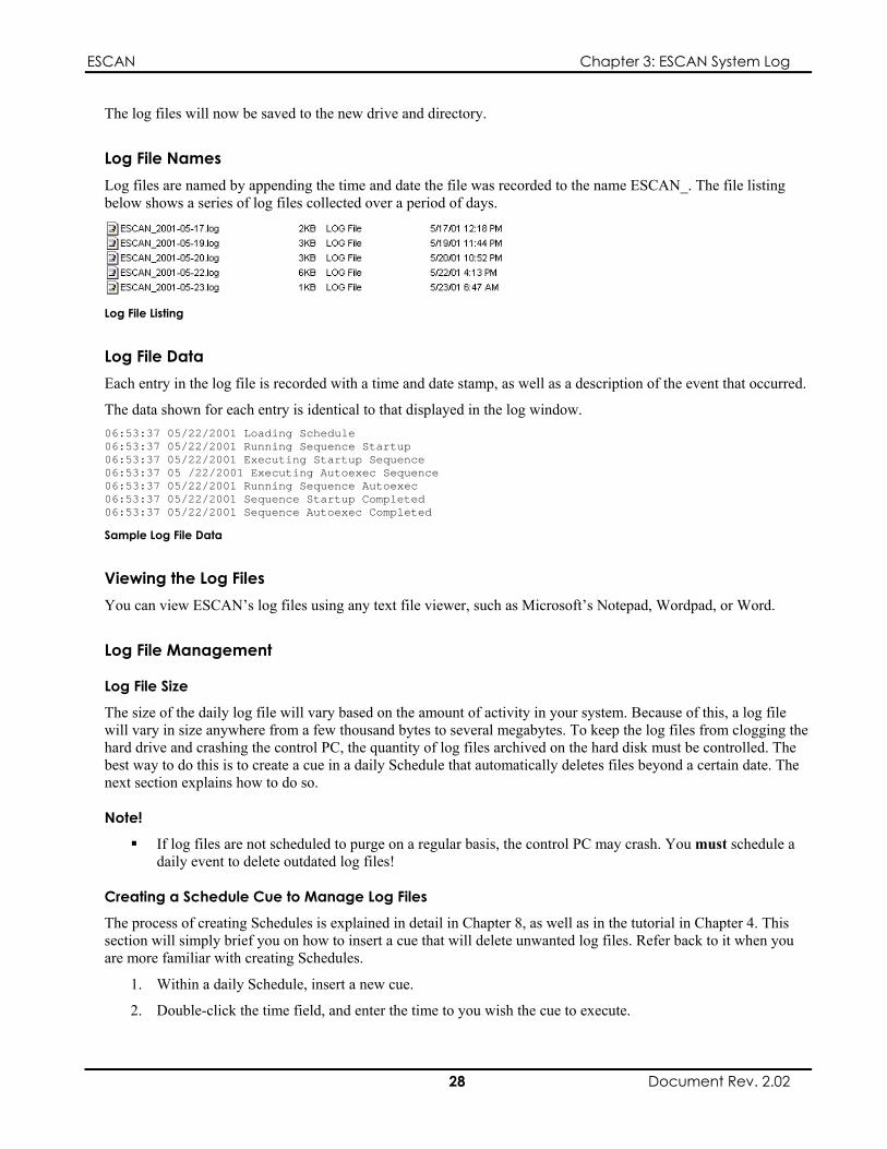
ESCAN Chapter 3: ESCAN System Log
The log files will now be saved to the new drive and directory.
Log File Names Log files are named by appending the time and date the file was recorded to the name ESCAN_. The file listing below shows a series of log files collected over a period of days.
Log File Listing
Log File Data Each entry in the log file is recorded with a time and date stamp, as well as a description of the event that occurred.
The data shown for each entry is identical to that displayed in the log window. 06:53:37 05/22/2001 Loading Schedule 06:53:37 05/22/2001 Running Sequence Startup 06:53:37 05/22/2001 Executing Startup Sequence 06:53:37 05 /22/2001 Executing Autoexec Sequence 06:53:37 05/22/2001 Running Sequence Autoexec 06:53:37 05/22/2001 Sequence Startup Completed 06:53:37 05/22/2001 Sequence Autoexec Completed
Sample Log File Data
Viewing the Log Files You can view ESCAN’s log files using any text file viewer, such as Microsoft’s Notepad, Wordpad, or Word.
Log File Management
Log File Size
The size of the daily log file will vary based on the amount of activity in your system. Because of this, a log file will vary in size anywhere from a few thousand bytes to several megabytes. To keep the log files from clogging the hard drive and crashing the control PC, the quantity of log files archived on the hard disk must be controlled. The best way to do this is to create a cue in a daily Schedule that automatically deletes files beyond a certain date. The next section explains how to do so.
Note!
If log files are not scheduled to purge on a regular basis, the control PC may crash. You must schedule a daily event to delete outdated log files!
Creating a Schedule Cue to Manage Log Files
The process of creating Schedules is explained in detail in Chapter 8, as well as in the tutorial in Chapter 4. This section will simply brief you on how to insert a cue that will delete unwanted log files. Refer back to it when you are more familiar with creating Schedules.
1. Within a daily Schedule, insert a new cue.
2. Double-click the time field, and enter the time to you wish the cue to execute.
28 Document Rev. 2.02
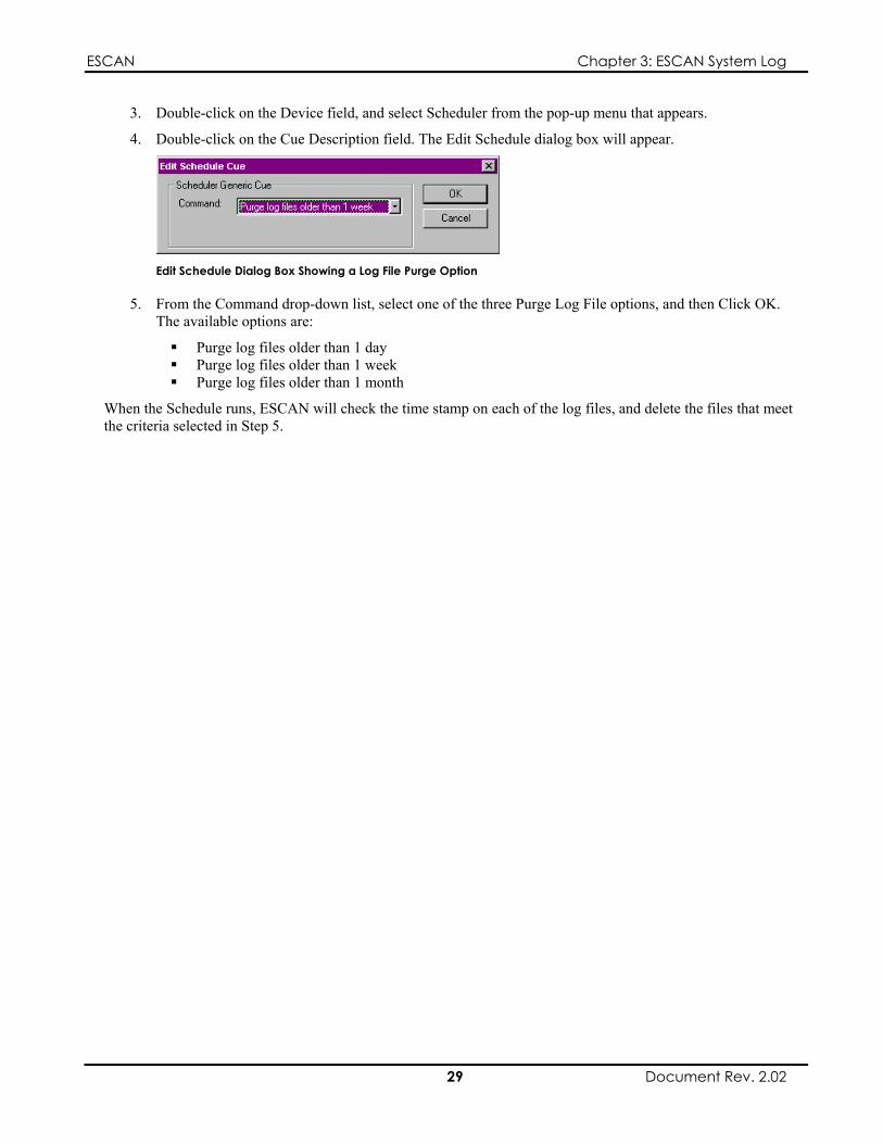
ESCAN Chapter 3: ESCAN System Log
3. Double-click on the Device field, and select Scheduler from the pop-up menu that appears.
4. Double-click on the Cue Description field. The Edit Schedule dialog box will appear.
Edit Schedule Dialog Box Showing a Log File Purge Option
5. From the Command drop-down list, select one of the three Purge Log File options, and then Click OK. The available options are:
Purge log files older than 1 day Purge log files older than 1 week Purge log files older than 1 month
When the Schedule runs, ESCAN will check the time stamp on each of the log files, and delete the files that meet the criteria selected in Step 5.
29 Document Rev. 2.02
ESCAN Chapter 3: ESCAN System Log
This page intentionally left blank.
30 Document Rev. 2.02

ESCAN Chapter 4: Tutorial
Chapter 4: Tutorial
Tutorial Overview
This tutorial will teach you basic setup and operation of ESCAN. It will not cover all aspects of the software, but will instead walk you through a typical configuration session.
The Tutorial “System”
The tutorial assumes a system of the following configuration:
An ESCAN control PC A JVC SR-S365U VHS Player An Extron M200 switcher A video camera providing a live feed A CRT Projector
ESCAN PCExtron M200
SwitcherRS-232
RS-232
JVCSR-S365U Live Video Feed
CRT Projector
Tutorial System Block Diagram
In this tutorial, you will control the VCR and the switcher. In reality, it would be possible to configure a more advanced system that allowed for control of the camera and projector as well.
Tutorial Goals
When finished with the tutorial, you will know how to:
Configure serial communications ports Define Devices Define Sequences Set up and run a simple Schedule Check the Log file for system activity
Refer to Chapters 5 to 10 for detailed descriptions of ESCAN’s functions.
Creating the Tutorial File
The tutorial is comprised of the following steps:
Configuring two PC-resident serial ports Defining JVC SR-S365U VCR and Extron M200 Switcher devices Defining control Sequences for the VCR and switcher Defining a Schedule to run the VCR and switcher Sequences Running the Schedules Reviewing the Log file for system activity
31 Document Rev. 2.02

ESCAN Chapter 4: Tutorial
For the purpose of this tutorial, it is not necessary to have a JVC VCR or Extron switcher. It is more important that you learn the processes involved in configuring and integrating various system elements within the software.
Creating a New File
To create a new file, click on the New File button, or select File | New from the top line menu.
ESCAN’s New File Button
A new, empty file called “Untitled1.ess” (or similar name) will be created.
Saving the File
Before getting started, you should save the file.
To save the file, click on ESCAN’s Save button, or select File | Save from the top line menu.
ESCAN’s Save Button
Windows’ Save As dialog box will appear. Assign the name “Tutorial” to the file, and click Save.
Defining the System’s Frame Rate
To begin the tutorial, you will set the system’s frame rate. If your country utilizes the PAL video system, set the frame rate to 25. If your country utilizes the NTSC video system, set the frame rate to 30.
Setting the Frame Rate
1. Select Scheduler | Configuration Options… from the main menu. The ESCAN Configuration dialog box will appear.
2. Click on the Frame Rate tab.
ESCAN Configuration Frame Rate Tab
3. Select the appropriate frame rate, and click OK.
32 Document Rev. 2.02

ESCAN Chapter 4: Tutorial
More information on this topic can be found in Chapter 2, “The ESCAN Scheduler.”
Configuring Communication Ports
A communication port must be defined in order to send data to an external device. You will now define a serial port to control a JVC VCR, and a serial port to control an Extron switcher.
Defining the First Com Port
1. Right-click on the Comms icon in the Workspace tree.
The Comms icon
2. Click on Add Comm Port from the pop-up menu that appears.
Comms Pop-Up Menu
The Communications Port Setting dialog box will appear.
3. Type “JVC VCR Control Port” in the Name field.
4. Select the RS232 option.
5. In the Port field, type “1.” This corresponds to Com port 1 on the PC.
6. In the Baud field, select “9600.”
7. In the Data bits field, Select “8”.
8. In the Parity field, select “Even.”
9. In the Stop bits field, select “2”.
10. Make sure the dialog box looks like the example shown below, and then click the OK button.
Proper Settings for the JVC VCR Port
33 Document Rev. 2.02
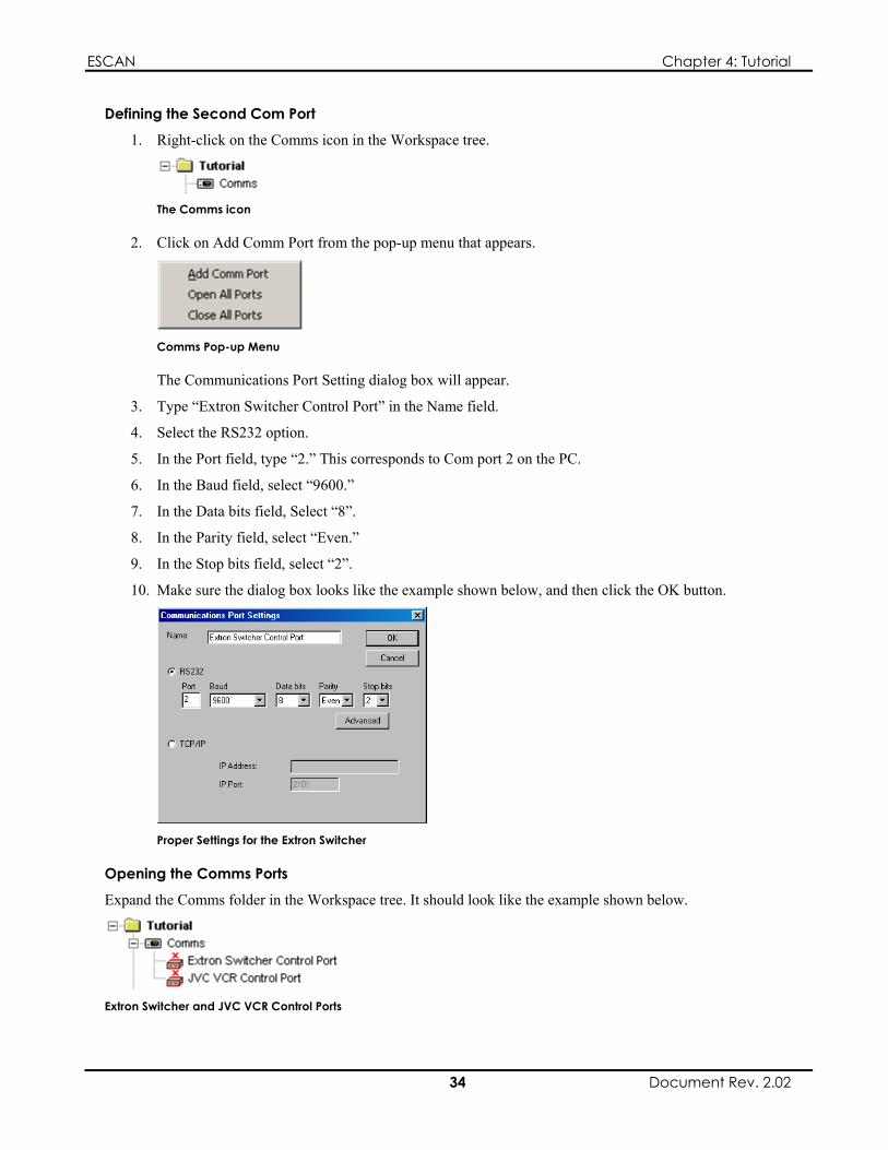
ESCAN Chapter 4: Tutorial
Defining the Second Com Port
1. Right-click on the Comms icon in the Workspace tree.
The Comms icon
2. Click on Add Comm Port from the pop-up menu that appears.
Comms Pop-up Menu
The Communications Port Setting dialog box will appear.
3. Type “Extron Switcher Control Port” in the Name field.
4. Select the RS232 option.
5. In the Port field, type “2.” This corresponds to Com port 2 on the PC.
6. In the Baud field, select “9600.”
7. In the Data bits field, Select “8”.
8. In the Parity field, select “Even.”
9. In the Stop bits field, select “2”.
10. Make sure the dialog box looks like the example shown below, and then click the OK button.
Proper Settings for the Extron Switcher
Opening the Comms Ports
Expand the Comms folder in the Workspace tree. It should look like the example shown below.
Extron Switcher and JVC VCR Control Ports
34 Document Rev. 2.02

ESCAN Chapter 4: Tutorial
The red “X” above each control port icon signifies that the port is not open. This means that data will not be transmitted from that port.
To open a port, right-click on its control port icon, and select Open Port from the pop-up menu.
Control Port Pop-Up Menu
The red “X” will disappear, and the control port icon will turn green.
Note
If the red “X” does not disappear and the control port icon does not turn green, the port may be unavailable on your PC, or the device is not responding. For the purpose of this tutorial, it is not necessary to actually open the ports.
More information on this topic can be found in Chapter 5, “The Comms Branch.”
Adding Devices
Having configured your communication ports, you will now define some devices. A device is typically a piece of hardware that you wish to control from ESCAN, such as a switcher or DVD player.
In this tutorial, you will define two devices: a JVC VCR, and an Extron switcher.
Defining the JVC VCR Device
1. Right-click on the Devices icon in the Workspace tree.
The Devices Icon
2. Click on Add Device from the pop-up menu that appears.
Device Pop-Up Menu
The Add Device dialog box will appear.
3. From the Device Type drop-down list, select “JVC SR-S365U VCR.”
4. In the Device Name field, type “JVC SR-S365U VCR.”
5. Make sure the dialog box looks like the example shown below, and then click OK.
35 Document Rev. 2.02

ESCAN Chapter 4: Tutorial
Proper Settings for the JVC VCR Device
A Properties dialog box for the VCR will open.
6. From the Comms tab, you will choose the communication port you defined for the VCR earlier in the tutorial. Click on the drop-down list, and choose “JVC VCR Control Port.”
7. Leave the Enable Receive box checked. Make sure the dialog box looks like the example shown below, and then click OK.
VCR Properties
Defining the Extron Switcher Device
1. Right-click on the Devices icon in the Workspace tree.
The Devices Icon
2. Click on Add Device from the pop-up menu that appears.
Device Pop-Up Menu
The Add Device dialog box will appear
3. From the Device Type drop-down list, select “EXTRON M200 Switcher.”
4. In the Device Name field, type “EXTRON M200 Switcher.”
36 Document Rev. 2.02

ESCAN Chapter 4: Tutorial
5. Make sure the dialog box looks like the example shown below, and then click OK.
Proper Settings for the Extron M200 Device
A Properties dialog box for the switcher will open.
8. From the Comms tab, you will choose the communication port you defined for the switcher earlier in the tutorial. Click on the drop-down list, and choose “Extron Switcher Control Port.” Leave the Enable Receive box checked.
Switcher Comms Properties
9. Click on the first Device Names tab. From this tab, you will assign more meaningful names to the switcher inputs.
10. Click once, pause, and then click again on Input 1 under the Name field. The text should highlight, allowing you to rename the channel. Rename Input 1 “VCR.”
Input 1 Renamed as VCR
11. Repeat the above step, renaming Input 2 as “Camera.”
Input 2 Renamed as Camera
12. Click on the second Device Names tab. From this tab, you will assign more meaningful names to the switcher outputs.
37 Document Rev. 2.02

ESCAN Chapter 4: Tutorial
13. Click once, pause, and then click again on Output 1 under the Name field. Rename Output 1 “Projector.”
Output 1 Renamed as Projector
14. Click on OK.
Checking your work
Expand the Devices folder in the Workspace tree. It should look like the example shown below.
Extron Switcher and JVC VCR Devices
Note
The Scheduler and Variables devices are always present under the Devices icon; they cannot be deleted.
More information on this topic can be found in Chapter 6, “The Devices Branch.”
Defining Sequences
A Sequence is a collection of commands, commonly used to control one or more devices. A typical ESCAN file will contain many sequences, each performing a group of actions. Once defined, a sequence can later be executed via Schedule, or a Trigger.
This tutorial will contain four sequences:
Turn VCR Power On Play VCR, Switch VCR to Projector Switch Camera to Projector Rewind VCR
Defining the First Sequence
1. Right-click on the Sequences icon in the Workspace tree.
The Sequences Icon
2. Click on Add Sequence from the pop-up menu that appears.
38 Document Rev. 2.02

ESCAN Chapter 4: Tutorial
Sequences Pop-Up Menu
The Create New Sequence dialog box will appear.
3. Type “Power VCR On” in the text field, and click OK. An icon for the Sequence will be created under the Sequences branch in the Workspace tree with the name you assigned to it, and the Sequence window will appear.
Create New Sequence Dialog Box
The Sequence Window
The Sequence window provides the means necessary to create a list of events that will control the devices in your system.
4. Double-click on the gray line that bears the text “Double-Click or Select and Press Enter to Add New Cue.” A blank cue (Cue 0001) will appear that will eventually contain the data required to power on the VCR.
5. Double-click on cue 0001’s Device field, and select JVC SR-S365U VCR from the menu that appears.
Device Options
6. Double-click on cue 0001’s Cue Description field. A dialog box will appear, allowing you to select a control action for the VCR.
7. Select Power On from the dialog box’s drop-down list, and click OK.
Power On Selected for the VCR
8. Double-click on cue 0001’s Time Type field, and select WAIT from the drop-down list.
39 Document Rev. 2.02

ESCAN Chapter 4: Tutorial
The WAIT Time Type
9. Double-click on cue 0001’s Time field, make sure the time is set to 00:00:00.00, and click on Done. This action will cause the cue to execute immediately when the Sequence is run.
Cue 0001 should now look like:
The Completed Cue 0001
10. Close the Sequence window.
You have now completed the first Sequence, which contains a single cue to turn on the VCR. The next Sequence you define will contain two cues: one to play the VCR and one to switch the switcher to the VCR input.
Defining the Second Sequence
This sequence will be slightly more involved than the last one. It will contain two cues: one to switch the switcher to the VCR input and one to play the VCR.
1. Right-click on the Sequences icon in the Workspace tree.
2. Click on Add Sequence from the pop-up menu that appears.
The Create New Sequence dialog box will appear
3. Type “Play VCR” in the text field, and click OK. An icon for the Sequence will be created under the Sequences branch in the Workspace tree with the name you assigned to it, and the Sequence window will appear.
Create New Sequence Dialog Box
4. Double-click on the gray line that bears the text “Double-Click or Select and Press Enter to Add New Cue.”
5. Double-click on cue 0001’s Time Type field, and select WAIT from the drop-down list.
The WAIT Time Type
6. Double-click on cue 0001’s Time field, make sure the time is set to 00:00:00.00, and click on Done.
7. Double-click on cue 0001’s Device field, and select JVC SR-S365U VCR from the menu that appears.
8. Double-click on cue 0001’s Cue Description field.
40 Document Rev. 2.02

ESCAN Chapter 4: Tutorial
9. Select Play from the dialog box’s drop-down list, and click OK.
Play Selected for the VCR
Cue 0001 should now look like:
The Completed Cue
10. Double-click on the line below cue 0001 to add a new cue.
11. Double-click on cue 0002’s Time Type field, and select WAIT from the drop-down list.
The WAIT Time Type
12. Double-click on cue 0002’s Time field, use the sliders to set a time of 00:00:05.00 (5 seconds), and click on Done. This action will cause the cue to execute 5 seconds after the previous cue executes.
Setting the Wait Time to Five Seconds
13. Double-click on cue 0002’s Device field, and select Extron M200 Switcher from the menu that appears.
14. Double-click on cue 0002’s Cue Description field. The Edit Extron Switcher Cue dialog box will appear. Note that the names you assigned to the relevant inputs and output are displayed.
15. Click on the connector next to the VCR label, and then click on the connector next to the Projector label. A line will connect the two, indicating that the VCR signal will now be routed to the projector. Click on OK.
41 Document Rev. 2.02

ESCAN Chapter 4: Tutorial
Extron Switcher Dialog Box Showing VCR Mapped to Projector
Your Sequence should now look like this:
The Completed Sequence
By now, you should be getting familiar with creating Sequences, and editing cues within them. You will receive less instruction for the next two tasks; if you need some assistance, review the instructions for the previous two Sequences you created.
Defining the Third Sequence
This Sequence will switch the camera to the projector’s input.
1. Create a new Sequence called “Switch Camera to Projector.”
2. Create Cue 0001.
3. Set the Time Type to WAIT.
4. Set the time to 00:00:01.00 (1 second).
5. Set the device in the Device field to Extron M200 Switcher.
6. The Cue Description should route the camera (input 2) to the projector (output 1). The finished cue should look like this:
The Completed Cue
Defining the Fourth Sequence
This Sequence will rewind the VCR.
1. Create a new Sequence called “Rewind VCR.”
2. Create Cue 0001.
3. Set the Time Type to WAIT.
4. Set the time to 00:00:01.00 (1 second).
5. Set the device in the Device field to JVC SR-S365U VCR.
6. The Cue Description should rewind the VCR. The finished cue should look like this:
42 Document Rev. 2.02

ESCAN Chapter 4: Tutorial
The Completed Cue
Checking your work
Expand the Sequences folder in the Workspace tree. It should look like the example shown below.
Current Sequence List
Note
The Autoexec and Startup Sequences are automatically created under the Sequences icon.
More information on this topic can be found in Chapter 7, “The Sequences Branch.”
Creating a Schedule
In the previous section, you created four Sequences. Typically, Sequences are executed by placing them in a Schedule where they will run at an assigned time of day. Alternatively, they can be run by an external input to the ESCAN PC (called a Trigger). In this tutorial, you will create a Schedule to run your sequences.
More information on Triggers can be found in Chapter 9, “The Triggers Branch.”
Opening the Daily Schedule
One type of Schedule is a Daily schedule, where the assigned events will happen every day at the specified time.
A new ESCAN file automatically contains a Daily schedule. In this tutorial, you will use it to create the Schedule that runs your Sequences.
To open the Daily Schedule, perform the following procedure:
1. Expand the Schedules folder in the Workspace tree. The Daily Schedule icon will appear.
The Daily Schedule Icon
2. Double-click on the Daily icon. The Daily Schedule window will appear.
The Daily Schedule Window
43 Document Rev. 2.02

ESCAN Chapter 4: Tutorial
Adding the First Event to the Daily Schedule
The first event you will add to the Schedule is the Sequence that powers on the VCR.
1. Double-click on the line that bears the text “Double-Click or Select and Press Enter to Add New Cue.” A blank line (0001) will appear that will hold the first Sequence.
2. Double-click on line 0001’s Cue Description field. The Edit Schedule Cue dialog box will appear.
3. From the Command drop-down list, select Run Sequence.
4. From the Control drop-down list, select Power VCR On, then click the OK button.
Power VCR On Sequence Selected
5. Double-click on line 0001’s Time field, use the sliders to set a time of 18:00:00 (6:00 p.m.), and click on Done. This action will cause the Power VCR On Sequence to run at 6:00 p.m. (as referenced by the PC’s internal clock).
Setting the Time to 18:00:00 (6:00 pm)
Note
Times are entered in “military style”, based on a 24 hour clock. For example, 6:00 p.m. is entered as 18:00:00.
The first line in your Schedule should look like this:
First Event Added to the Daily Schedule
Adding the Second Event to the Schedule
The second event you will add to the Schedule is the Sequence that plays the VCR, and switches the switcher to the VCR input.
1. Double-click on the gray line below line 0001 to add a new cue. A blank line (0002) will appear that will hold the second Sequence.
2. Double-click line 0002’s Time field, use the sliders to set a time of 18:00:10, and click on Done.
3. Make sure the Device/Seq field is set to Scheduler.
4. Double-click on line 0002’s Cue Description field. The Edit Schedule Cue dialog box will appear.
5. From the Command drop-down list, select Run Sequence.
6. From the Control drop-down list, select Play VCR, then click the OK button.
44 Document Rev. 2.02

ESCAN Chapter 4: Tutorial
Play VCR Sequence Selected
By now, you should be getting familiar with adding events to the Schedule list. You will receive less instruction for the next two tasks; if you need some assistance, review the instructions for the previous two events you added.
Adding the Third Event to the Schedule
The third event you will add to the Schedule is the Sequence that switches the camera to the switcher’s output.
1. Add a new cue to the Schedule list.
2. Assign a time of 18:10:00 to the event.
3. Make sure the Device/Seq field is set to Scheduler.
4. The action in the Cue Description field should run the sequence called Switch Camera to Projector.
Switch Camera to Projector Sequence Selected
Adding the Fourth Event to the Schedule
The last event you will add to the Schedule will rewind the VCR.
1. Add a new cue to the Schedule list.
2. Assign a time of 18:10:10 to the event.
3. Make sure the Device/Seq field is set to Scheduler.
4. The action in the Cue Description field should run the sequence called Rewind VCR.
Rewind VCR Sequence Selected
Checking your Work
The completed Schedule list should look like the example shown below:
Completed Schedule List
45 Document Rev. 2.02
Below is a flow diagram of how the Schedule will run the Sequences.

ESCAN Chapter 4: Tutorial
Power VCR On SequencePower VCR OnWait 00:00:00.00
Play VCR SequencePlay VCRWait 00:00:00.00Switch Extron to VCRWait 00:00:05.00
Switch Camera to Projector SequenceSwitch Extron to CameraWait 00:00:01.00
Daily Schedule
18:00:00
18:00:10
18:10:00
18:10:10
Run Power VCR On Sequence
Run Play VCR Sequence
Run Switch Camera to Projector Sequence
Run Rewind VCR Sequence
Rewind VCR SequenceRewind VCRWait 00:00:00.00
Flow Diagram of Daily Schedule
Running the Schedule
Running the Schedule
To run the Schedule, perform the following procedure:
1. Push in the Activate Scheduler button on the main toolbar. The Scheduler will start, ESCAN will attempt to connect to all attached devices, and the Daily Schedule will begin running.
Activate Scheduler Button
Note
Devices must be “connected” in order for ESCAN to communicate with them. For the purpose of this tutorial, you can ignore any errors or messages indicating failed connections.
2. Expand the Schedules icon in the Workspace tree so the Daily Schedule is visible. A “Play” arrow should appear in the icon, indicating that the Schedule is running.
Daily Schedule Running
3. If the Schedule does not appear to be running, right-click on the Daily icon, and select Run Schedule from the pop-up menu that appears.
Daily Schedule Pop-Up Menu
46 Document Rev. 2.02

ESCAN Chapter 4: Tutorial
An arrow will appear in the Daily icon to signify that the Schedule is running.
Daily Schedule Running
Now, when the time assigned to each scheduled event arrives, the designated Sequences will run.
Note
You may wish to change the time on your PC’s clock to a few minutes before the time assigned to your first Schedule cue. Then, when the time arrives, your Sequences will run.
A Daily Schedule can only run once per day. If your schedule does not run, reset the PC’s clock time as mentioned in the above note, and select Scheduler | Reload Schedule from the topline menu.
Stopping the Schedule
To stop the Schedule, right-click on the Daily Schedule icon, and select Suspend Schedule from the pop-up menu.
More information on Schedules can be found in Chapter 8, “The Schedules Branch.”
Reviewing Log Activity
ESCAN’s log allows you to keep track of the events that have occurred in your system. For example, the log shows you when Sequences were run, when the individual cues in the Sequence were executed, when the Sequences finished running, and other useful information. A log file also shows errors that were encountered when the Sequences ran.
Let’s look at a log file that could result from running the Tutorial’s daily Schedule.
Note
In the log file below, the JVC VCR and Extron switcher were reported as not responding and as off-line, respectively. This is because when the tutorial was created, the VCR and switcher were not actually connected to the ESCAN PC. Your log file may differ slightly, for this same reason.
Log File from the Tutorial’s Daily Schedule
More information on the system log can be found in Chapter 3, “ESCAN System Log.”
47 Document Rev. 2.02

ESCAN Chapter 4: Tutorial
What You’ve Accomplished
Having completed the tutorial you have learned how to:
Configure two PC-resident serial ports Define JVC SR-S365U VCR and Extron M200 Switcher devices Define control Sequences for the VCR and switcher Define a Schedule to run the VCR and switcher Sequences on a daily basis Run a daily Schedule Review the Log file for system activity
You can now begin to create an ESCAN file that will control a system of your own. For more information about each of ESCAN’s features, refer to the appropriate chapter:
For more information on Com port definition, refer to Chapter 5, “The Comms Branch.” For more information on defining devices, refer to Chapter 6, “The Device Branch.” For more information on Sequence definition, refer to Chapter 7, “The Sequences Branch.” For more information on Schedules, refer to Chapter 8, “The Schedules Branch.”
48 Document Rev. 2.02
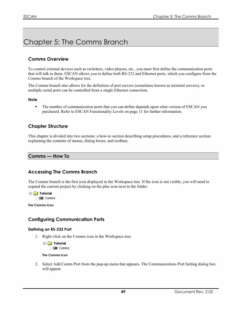
ESCAN Chapter 5: The Comms Branch
Chapter 5: The Comms Branch
Comms Overview
To control external devices such as switchers, video players, etc., you must first define the communication ports that will talk to them. ESCAN allows you to define both RS-232 and Ethernet ports, which you configure from the Comms branch of the Workspace tree.
The Comms branch also allows for the definition of port servers (sometimes known as terminal servers), so multiple serial ports can be controlled from a single Ethernet connection.
Note
The number of communication ports that you can define depends upon what version of ESCAN you purchased. Refer to ESCAN Functionality Levels on page 11 for further information.
Chapter Structure
This chapter is divided into two sections: a how-to section describing setup procedures, and a reference section explaining the contents of menus, dialog boxes, and toolbars.
Comms — How To
Accessing The Comms Branch
The Comms branch is the first icon displayed in the Workspace tree. If the icon is not visible, you will need to expand the current project by clicking on the plus icon next to the folder.
The Comms Icon
Configuring Communication Ports
Defining an RS-232 Port
1. Right-click on the Comms icon in the Workspace tree.
The Comms icon
2. Select Add Comm Port from the pop-up menu that appears. The Communications Port Setting dialog box will appear.
49 Document Rev. 2.02

ESCAN Chapter 5: The Comms Branch
Add Comm Port Option
The Communications Port Setting dialog box is explained on page 53.
3. Type a name for the port in the Name field.
4. Select the RS232 option.
5. In the Port field, enter the desired Com port number. A value of “1” corresponds to Com port 1 on the PC, a value of “2” corresponds to Com port 2, etc.
6. In the Baud field, select the desired baud rate.
7. In the Data bits field, select the desired number of data bits.
8. In the Parity field, select the desired parity.
9. In the Stop bits field, select the desired number of stop bits.
10. Click the OK button.
Defining an Ethernet Port
1. Right-click on the Comms icon in the Workspace tree.
The Comms icon
2. Select Add Comm Port from the pop-up menu that appears. The Communications Port Setting dialog box will appear.
Add Comm Port Option
The Communications Port Setting dialog box is explained on page 53.
3. Type a name for the port in the Name field.
4. Select the TCP/IP option.
5. In the TCP/IP field, enter the IP address or the computer name of the device you wish to control.
Note
If your network is running DHCP (dynamic addressing), you must enter the computer name as opposed to the IP address in this field.
6. In the IP Port field, enter IP port setting of the device you wish to control.
7. Click the OK button.
50 Document Rev. 2.02
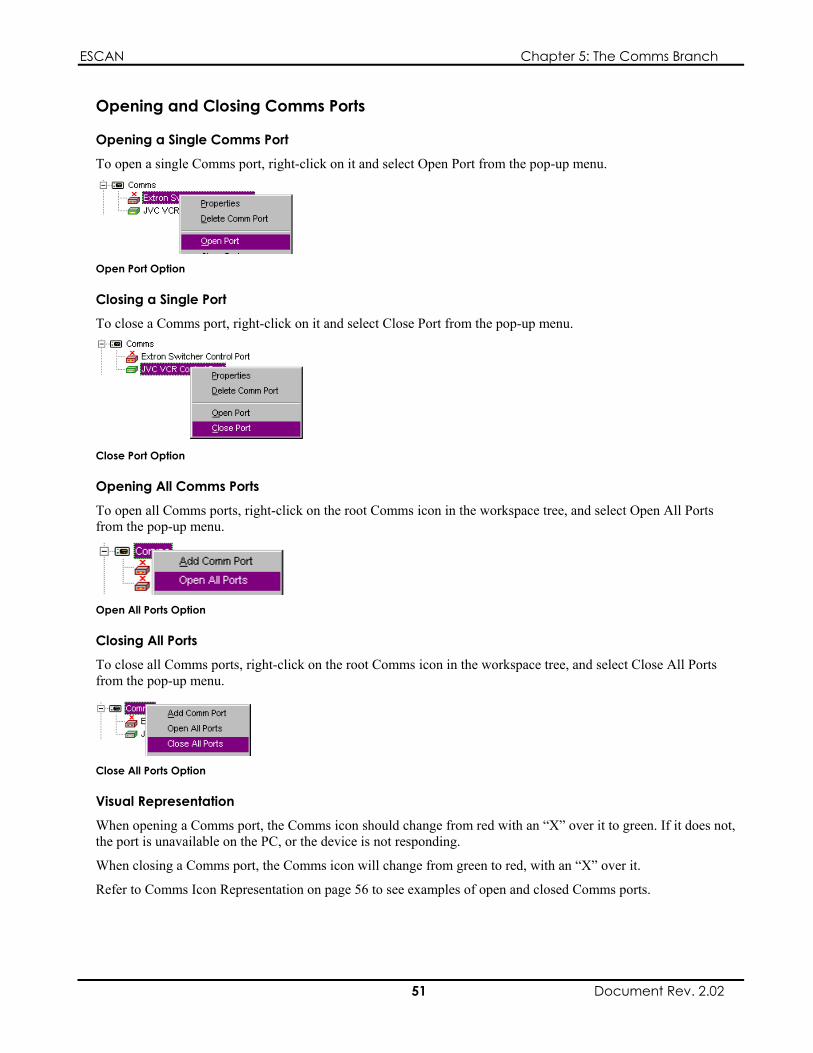
ESCAN Chapter 5: The Comms Branch
Opening and Closing Comms Ports
Opening a Single Comms Port
To open a single Comms port, right-click on it and select Open Port from the pop-up menu.
Open Port Option
Closing a Single Port
To close a Comms port, right-click on it and select Close Port from the pop-up menu.
Close Port Option
Opening All Comms Ports
To open all Comms ports, right-click on the root Comms icon in the workspace tree, and select Open All Ports from the pop-up menu.
Open All Ports Option
Closing All Ports
To close all Comms ports, right-click on the root Comms icon in the workspace tree, and select Close All Ports from the pop-up menu.
Close All Ports Option
Visual Representation
When opening a Comms port, the Comms icon should change from red with an “X” over it to green. If it does not, the port is unavailable on the PC, or the device is not responding.
When closing a Comms port, the Comms icon will change from green to red, with an “X” over it.
Refer to Comms Icon Representation on page 56 to see examples of open and closed Comms ports.
51 Document Rev. 2.02

ESCAN Chapter 5: The Comms Branch
Deleting a Comms Port
To delete a Comms port, perform the following procedure:
1. Right-click on the port you wish to delete, and select Delete Port from the pop-up menu that appears.
Delete Comms Port Option
2. You will be prompted with a warning message, asking if you are sure you wish to delete the port; select Yes to delete the port, or select No to cancel.
Viewing/Editing a Port’s Properties
To view a Comms port’s properties, right-click on the port and select Properties from the pop-up menu.
Properties Option
The Communications Port Setting dialog box will appear, showing the port’s properties. If desired, the properties can be altered.
The Communications Port Setting dialog box is explained on page 53.
Comms — Reference
The Comms Branch Menu
Right-clicking on the Comms icon produces a pop-up menu of the following options:
Add Comm Port Open All Ports Close All Ports
Each option is explained below.
Comms Pop-Up Menu
52 Document Rev. 2.02

ESCAN Chapter 5: The Comms Branch
Add Comm Port
Selecting Add Comm Port adds a new communication port under the Comms icon in the Workspace tree, and opens the Communications Port Settings dialog box. You use the Communications Port Settings dialog box to select the type of port (RS-232 or Ethernet), and to configure the port’s settings.
The Communication Port Settings dialog box is explained on page 53.
Open All Ports
Selecting Open All Ports will attempt to open all of the ports defined under the Comms icon in the Workspace tree. A port must be opened in order to communicate with its attached device.
The appearance of each Comms port icon indicates whether or not ESCAN was able to open the port. Refer to Opening and Closing Comms Ports on page 51 for additional information.
Close All Ports
Selecting Close All Ports will close all of the ports defined under the Comms icon in the Workspace tree.
The Communication Port Settings Dialog Box
The Communication Port Settings dialog box is used to configure the data parameters for the port you are defining.
The dialog box consists of three main areas:
A Name field An RS-232 region A TCP/IP region
Name Port Field
Define RS-232 Port Region
Define TCP/IP Port Region
The Communication Port Settings Dialog Box
The Name Field
Use the Name field to assign a descriptive name to the port you are creating.
The RS-232 Region
Use the RS-232 region to define the parameters for the outgoing RS-232 data.
Parameter Function RS-232 Selector Defines the port as an RS-232 port (as opposed to
Ethernet)
53 Document Rev. 2.02

ESCAN Chapter 5: The Comms Branch
Port Defines which PC-resident Com port you are defining; a value of “1” indicates Com1, a value of “2” indicates Com 2, etc.
Baud Sets the baud rate for the RS-232 data Data bits Sets the number of data bits for the RS-232 data Parity Sets the parity for the RS-232 data Stop bits Sets the number of stop bits for the RS-232 data Advanced Button Opens the Comm Timeouts dialog box; the Comm
Timeouts dialog box is explained on page 54
TCP/IP Region
Use the TCP/IP region to define the parameters for the outgoing TCP/IP data.
Parameter Function TCP/IP Selector Defines the port as a TCP/IP port (as opposed to
RS-232) IP Address Indicates the IP address of the controlled device in
a static IP configuration, or the device’s computer name in a dynamic addressing configuration
IP Port Defines the IP port for the TCP/IP communication; this value must match the IP Port setting of the device you are controlling
The Comm Timeouts Dialog Box
The Comm Timeouts dialog box allows you tailor how ESCAN processes the timing of incoming and outgoing RS-232 data strings.
Note
Adjusting the values in the Comm Timeouts dialog box is only necessary if you are having trouble communicating with serial devices. In most instances, you will not need to adjust these values.
The Comm Timouts Dialog Box
Parameter Function Read Interval Timeout Maximum time, in milliseconds, allowed to elapse
between the arrival of two characters on the communications line
54 Document Rev. 2.02

ESCAN Chapter 5: The Comms Branch
Parameter Function Read Total Timeout Multiplier
Multiplier, in milliseconds, used to calculate the total time-out period for read operations; for each read operation, this value is multiplied by the requested number of bytes to be read
Read Total Timeout Constant
Constant, in milliseconds, used to calculate the total time-out period for read operations; for each read operation, this value is added to the product of the ReadTotalTimeoutMultiplier member and the requested number of bytes
Write Total Timeout Multiplier
Multiplier, in milliseconds, used to calculate the total time-out period for write operations; for each write operation, this value is multiplied by the number of bytes to be written
Write Total Timeout Constant
Constant, in milliseconds, used to calculate the total time-out period for write operations; for each write operation, this value is added to the product of the WriteTotalTimeoutMultiplier member and the number of bytes to be written
The Comms Port Menu
Right-clicking on an individual Comms port in the workspace tree produces a pop-up menu of the following options:
Properties Delete Comm Port Open Port Close Port
Each option is explained below.
Comms Port Pop-Up Menu
Properties
Opens the Communications Port Properties dialog box, and displays the settings for the selected port. The settings can be changed by editing them and clicking on the OK button.
Delete Comm Port
Deletes the selected port. You will be prompted with a warning message, asking if you are sure you wish to delete the port.
Open Port
Attempts to open the selected port.
55 Document Rev. 2.02
The appearance of the Comms port icon indicates whether or not ESCAN was able to open the port. Refer to Opening and Closing Comms Ports on page 51 for additional information.
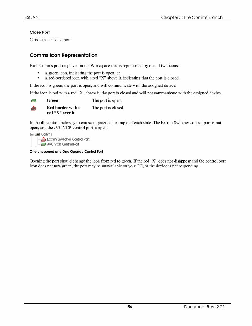
ESCAN Chapter 5: The Comms Branch
Close Port
Closes the selected port.
Comms Icon Representation
Each Comms port displayed in the Workspace tree is represented by one of two icons:
A green icon, indicating the port is open, or A red-bordered icon with a red “X” above it, indicating that the port is closed.
If the icon is green, the port is open, and will communicate with the assigned device.
If the icon is red with a red “X” above it, the port is closed and will not communicate with the assigned device.
Green The port is open.
Red border with a red “X” over it
The port is closed.
In the illustration below, you can see a practical example of each state. The Extron Switcher control port is not open, and the JVC VCR control port is open.
One Unopened and One Opened Control Port
Opening the port should change the icon from red to green. If the red “X” does not disappear and the control port icon does not turn green, the port may be unavailable on your PC, or the device is not responding.
56 Document Rev. 2.02

ESCAN Chapter 6: The Devices Branch
Chapter 6: The Devices Branch
Devices Overview
A system controlled by ESCAN will generally contain a number of devices. A device is typically (though not always) a piece of hardware that will perform a specific function, such as a DVD player to play video, a switcher to route video, a projector to display video, etc. You must define the devices in ESCAN before you can control them, and ESCAN’s Devices branch enables you to do so. Devices are typically defined after their respective Comms ports have been configured.
After you define the devices within ESCAN, they must be “connected”, or activated, so they can communicate with your actual equipment. This is done automatically when the Scheduler is activated. It can also be done manually from the main toolbar, or by right-clicking on a device and selecting Connect Device from its pop-up menu.
Chapter Structure
This chapter is divided into two sections: a how-to section describing setup procedures, and a reference section explaining the contents of menus, dialog boxes, and toolbars.
Devices — How To
Accessing the Devices Branch
The Devices branch is the second icon displayed in the Workspace tree. If the icon is not visible, you will need to expand the current project by clicking on the plus icon next to the folder.
The Devices Icon
Defining a Device
1. Right-click on the Devices icon in the Workspace tree.
The Devices Icon
Click on Add Device from the pop-up menu. The Add Device dialog box will appear.
57 Document Rev. 2.02

ESCAN Chapter 6: The Devices Branch
Device Pop-Up Menu
The Add Device dialog box is explained on page 60.
2. From the Device Type drop-down list, select the device driver for the piece of equipment you wish to control.
3. In the Device Name field, type in a name for the device.
4. Click the OK button.
5. After clicking the OK button, a properties dialog box, specific to the equipment driver you selected, will appear. Select the desired properties for the device, and click OK.
When finished, a new Device icon will appear under the Devices branch of the Workspace tree with the name specified in step 3.
Deleting a Device
Deleting a device is accomplished in the following manner:
1. Right-click on the device you wish to delete, and select Delete Device from the pop-up menu that appears.
2. You will be prompted with a warning message, asking if you are sure you wish to delete the device; select Yes to delete the device, or select No to cancel.
Alternatively, you can delete a device by clicking on it and pressing the Delete key on the keyboard.
Note
The Delete Device option is only active when the Scheduler is not running.
Viewing/Editing a Device’s Properties
To view a device’s properties, double-click on its name in the Workspace tree.
Alternatively, you can right-click on the device’s icon and select Properties from the pop-up menu.
Properties Option
A properties dialog box will appear. It will display the control port assigned to the device. Additional information may also be displayed, depending on the equipment type defined by the device. If desired, the properties can be altered.
Connecting and Disconnecting a Device
ESCAN must connect to a device in order to communicate with it. This occurs automatically when the Scheduler is activated. It can be performed manually as well.
58 Document Rev. 2.02

ESCAN Chapter 6: The Devices Branch
Connecting a Single Device
To connect a single device, right-click on it and select Connect Device from the pop-up menu.
Connect Device Option
Connecting All Devices
To connect all devices, click on the main toolbar’s Connect All Devices button, press F11, or select Scheduler | Connect Devices from the main menu.
Connect All Devices Button
Disconnecting a Single Device
To disconnect a single device, right-click on it and select Disconnect Device from the pop-up menu.
Disconnect Device Option
Disconnecting All Devices
To disconnect all devices, click on the main toolbar’s Disconnect All Devices button, press F12, or select Scheduler | Disconnect Devices from the main menu.
Disconnect All Devices Button
Note
You can only connect devices when the Scheduler is running, and the device’s Comms port is open. You can only disconnect devices when the Scheduler is running.
Visual Representation
The appearance of a device icon indicates whether or not it successfully connected to its respective device. Refer to Device Icon Representation on page 62 for additional information.
Devices — Reference
The Device Branch Menu
Right-clicking on the devices icon in the Workspace tree produces a pop-up menu with a single option:
Add Device
59 Document Rev. 2.02

ESCAN Chapter 6: The Devices Branch
Device Pop-Up Menu
Add Device
Selecting Add Device adds a new device under the devices icon in the Workspace tree, and opens the Add Device dialog box. You use the Add Device dialog box to choose which piece of equipment you will control.
The Add Device dialog box is explained below.
The Add Device Dialog Box
The Add Device dialog box is used to select the driver that will control a given piece of equipment, and to assign a name to the corresponding device icon.
The Add Device Dialog Box
Parameter Function Type Used to select the driver for the piece of equipment
you wish to control. Name Defines the name for the selected device.
After selecting the proper driver and assigning it a name, clicking OK will produce a properties dialog box for the device. The appearance of the properties dialog box will vary based on the equipment type you selected. For example, the properties dialog box for a VCR will differ from that of an MS VideoServer.
Device Menu
Right-clicking on a defined device in the Workspace tree produces a pop-up menu with the following options:
Properties Delete Device Rename Connect Device Disconnect Device Monitor Device Comm
Each option is explained below.
60 Document Rev. 2.02
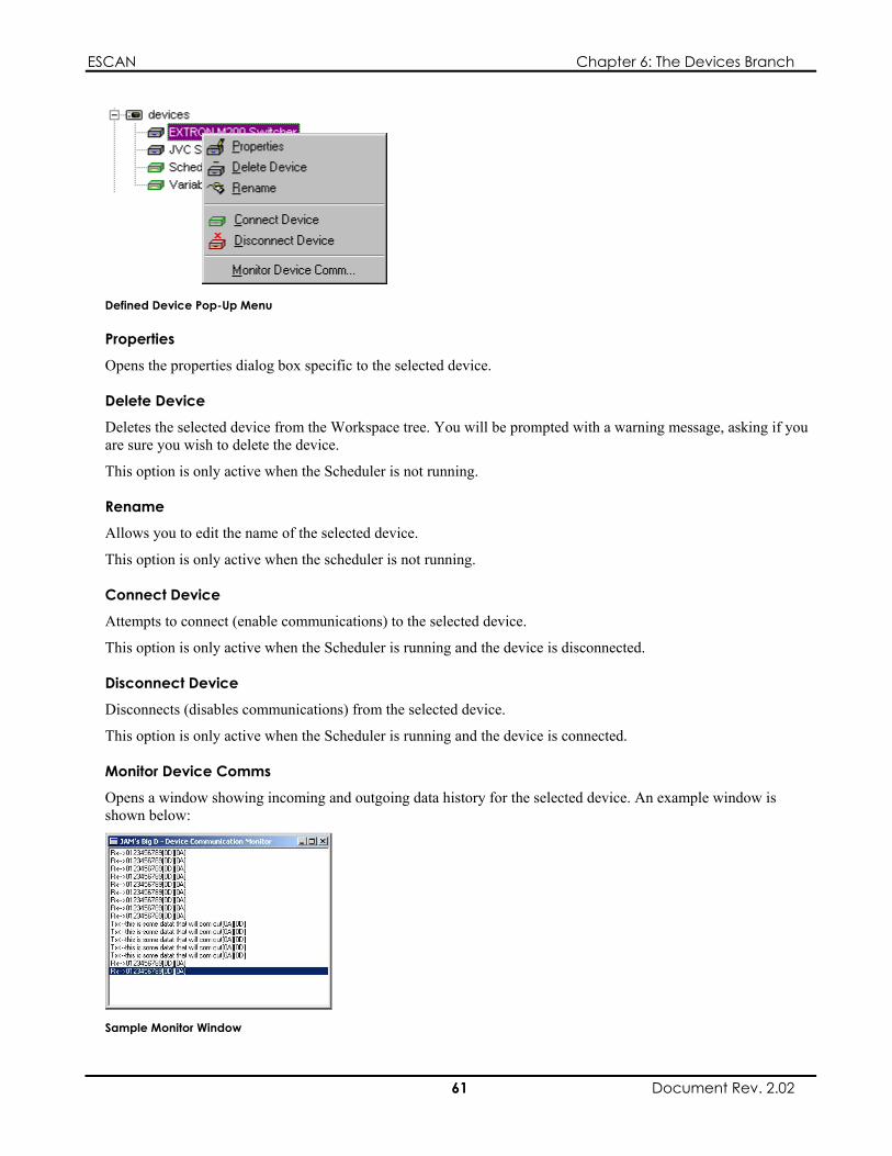
ESCAN Chapter 6: The Devices Branch
Defined Device Pop-Up Menu
Properties
Opens the properties dialog box specific to the selected device.
Delete Device
Deletes the selected device from the Workspace tree. You will be prompted with a warning message, asking if you are sure you wish to delete the device.
This option is only active when the Scheduler is not running.
Rename
Allows you to edit the name of the selected device.
This option is only active when the scheduler is not running.
Connect Device
Attempts to connect (enable communications) to the selected device.
This option is only active when the Scheduler is running and the device is disconnected.
Disconnect Device
Disconnects (disables communications) from the selected device.
This option is only active when the Scheduler is running and the device is connected.
Monitor Device Comms
Opens a window showing incoming and outgoing data history for the selected device. An example window is shown below:
Sample Monitor Window
61 Document Rev. 2.02

ESCAN Chapter 6: The Devices Branch
A device’s comms window will show a maximum of 1000 data events. The events displayed are from the current ESCAN session; i.e., if the ESCAN application is closed and then reopened, the data history for each device will be cleared.
Received or transmitted characters with a decimal value of 32 through 126 (hex 20 through hex 7E) will be displayed in the window as the given ASCII character. All other values will be displayed in the window as a hex pair enclosed in brackets; i.e., “[0D]”.
This option is only active for devices that transmit and receive data.
Note
If you reassign the comms port for a given device, you must close and reopen its comms window before trying to monitor the data.
Scheduler and Variables Devices
Two icons are always present in the Devices branch: Scheduler, and Variables. These cannot be deleted, and are present so that Scheduler and Variable functions can be included in Sequences and Schedules.
Scheduler and Variables Icons in the Devices List
Device Icon Representation
The icons in the devices branch take on a different appearance when the Scheduler is running.
When the Scheduler is not running, the icons are gray.
When the Scheduler is running, the icons are:
green, indicating that the device is connected, or bordered in red below a red “X” indicating the device is not connected, or red, indicating that there was an error communicating with the device.
Gray Scheduler not running.
Green The device is connected.
Red Border with a red “X” over it
The device is not connected
Red There was an error communicating with the device.
62 Document Rev. 2.02
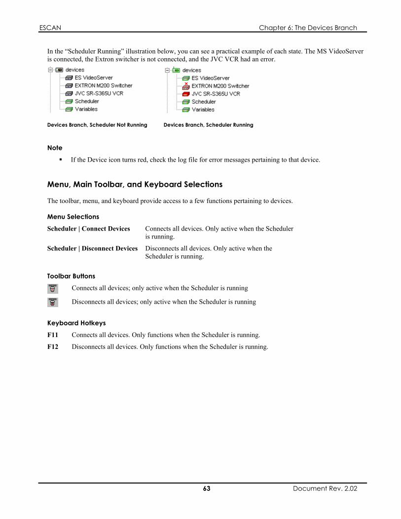
ESCAN Chapter 6: The Devices Branch
In the “Scheduler Running” illustration below, you can see a practical example of each state. The MS VideoServer is connected, the Extron switcher is not connected, and the JVC VCR had an error.
Devices Branch, Scheduler Not Running Devices Branch, Scheduler Running
Note
If the Device icon turns red, check the log file for error messages pertaining to that device.
Menu, Main Toolbar, and Keyboard Selections
The toolbar, menu, and keyboard provide access to a few functions pertaining to devices.
Menu Selections
Scheduler | Connect Devices Connects all devices. Only active when the Scheduler is running.
Scheduler | Disconnect Devices Disconnects all devices. Only active when the Scheduler is running.
Toolbar Buttons
Connects all devices; only active when the Scheduler is running
Disconnects all devices; only active when the Scheduler is running
Keyboard Hotkeys
F11 Connects all devices. Only functions when the Scheduler is running.
F12 Disconnects all devices. Only functions when the Scheduler is running.
63 Document Rev. 2.02

ESCAN Chapter 6: The Devices Branch
This page intentionally left blank.
64 Document Rev. 2.02
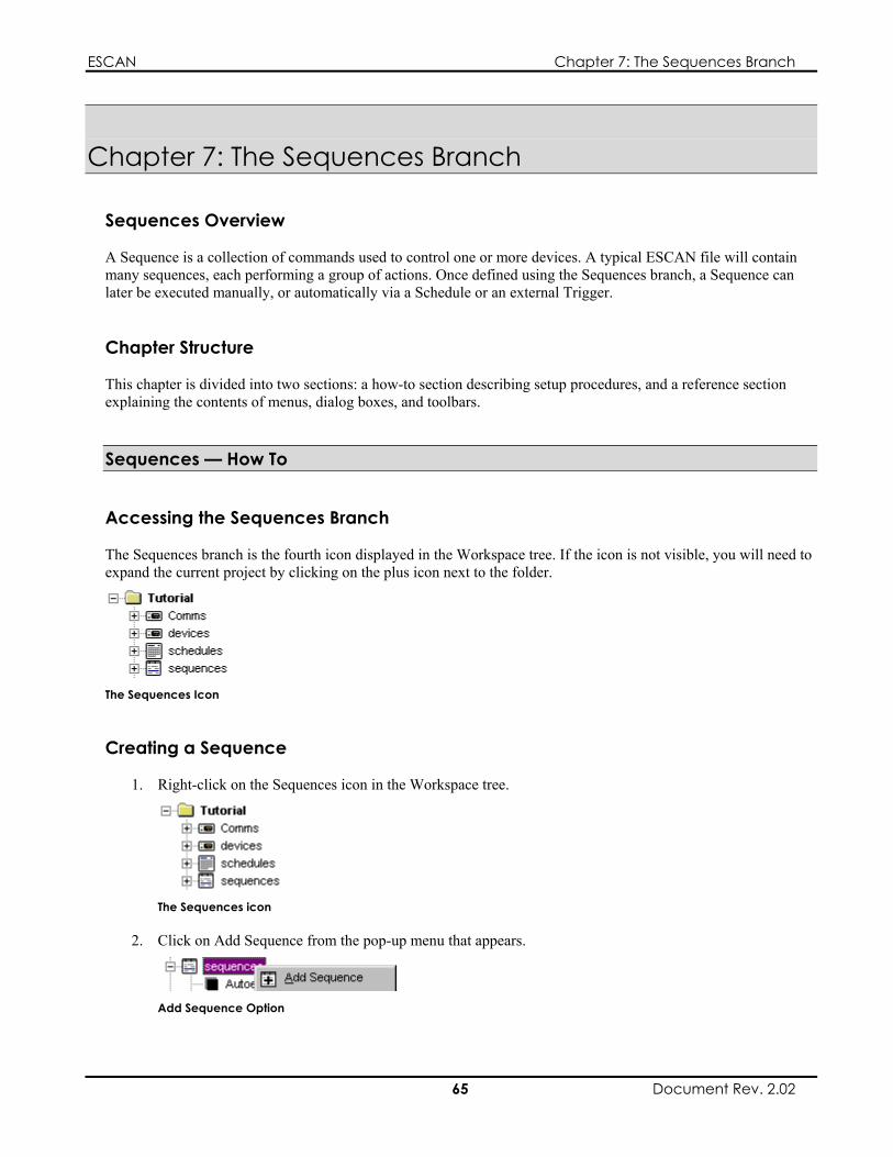
ESCAN Chapter 7: The Sequences Branch
Chapter 7: The Sequences Branch
Sequences Overview
A Sequence is a collection of commands used to control one or more devices. A typical ESCAN file will contain many sequences, each performing a group of actions. Once defined using the Sequences branch, a Sequence can later be executed manually, or automatically via a Schedule or an external Trigger.
Chapter Structure
This chapter is divided into two sections: a how-to section describing setup procedures, and a reference section explaining the contents of menus, dialog boxes, and toolbars.
Sequences — How To
Accessing the Sequences Branch
The Sequences branch is the fourth icon displayed in the Workspace tree. If the icon is not visible, you will need to expand the current project by clicking on the plus icon next to the folder.
The Sequences Icon
Creating a Sequence
1. Right-click on the Sequences icon in the Workspace tree.
The Sequences icon
2. Click on Add Sequence from the pop-up menu that appears.
Add Sequence Option
65 Document Rev. 2.02
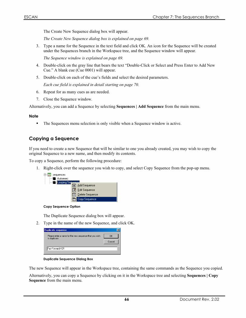
ESCAN Chapter 7: The Sequences Branch
The Create New Sequence dialog box will appear.
The Create New Sequence dialog box is explained on page 69.
3. Type a name for the Sequence in the text field and click OK. An icon for the Sequence will be created under the Sequences branch in the Workspace tree, and the Sequence window will appear.
The Sequence window is explained on page 69.
4. Double-click on the gray line that bears the text “Double-Click or Select and Press Enter to Add New Cue.” A blank cue (Cue 0001) will appear.
5. Double-click on each of the cue’s fields and select the desired parameters.
Each cue field is explained in detail starting on page 70.
6. Repeat for as many cues as are needed.
7. Close the Sequence window.
Alternatively, you can add a Sequence by selecting Sequences | Add Sequence from the main menu.
Note
The Sequences menu selection is only visible when a Sequence window is active.
Copying a Sequence
If you need to create a new Sequence that will be similar to one you already created, you may wish to copy the original Sequence to a new name, and then modify its contents.
To copy a Sequence, perform the following procedure:
1. Right-click over the sequence you wish to copy, and select Copy Sequence from the pop-up menu.
Copy Sequence Option
The Duplicate Sequence dialog box will appear.
2. Type in the name of the new Sequence, and click OK.
Duplicate Sequence Dialog Box
The new Sequence will appear in the Workspace tree, containing the same commands as the Sequence you copied.
Alternatively, you can copy a Sequence by clicking on it in the Workspace tree and selecting Sequences | Copy Sequence from the main menu.
66 Document Rev. 2.02

ESCAN Chapter 7: The Sequences Branch
Note
The Sequences menu selection is only visible when a Sequence window is active.
Viewing/Editing a Sequence
To view a Sequence, double-click on its name in the Workspace tree.
Alternatively, right-click on it and select Edit Sequence from the pop-up menu.
Edit Sequence Option
The Sequence window will open, showing the cue list for the selected Sequence.
The cue list can now be edited or appended.
Deleting a Sequence
Deleting a Sequence is accomplished in the following manner:
1. Right-click on the Sequence you wish to delete, and select Delete Sequence from the pop-up menu that appears.
Delete Sequence Option
2. You will be prompted with a warning message, asking if you are sure you wish to delete the Sequence; select OK to delete the Sequence, or select Cancel to cancel.
Alternatively, you can delete a Sequence by clicking on it in the Workspace tree and pressing the Delete key on the keyboard, or selecting Sequences | Delete Sequence from the main menu.
Note
The Sequences menu selection is only visible when a Sequence window is active.
Deleting a Cue in a Sequence
To delete a cue in a Sequence, perform the following procedure:
1. Click on the cue you wish to delete
2. Press the DEL key on the keyboard
67 Document Rev. 2.02

ESCAN Chapter 7: The Sequences Branch
Manually Running a Sequence
Typically, a Schedule or trigger will launch the Sequences in your ESCAN file. You may, however, wish to run a Sequence outside of a Schedule to test it.
To run a Sequence, right-click on it and select Run Sequence from the pop-up menu.
Run Sequence Option
Alternatively, you can run a Sequence by selecting Sequences | Run Sequence from the main menu.
Note
If the Scheduler is not running, ESCAN will not communicate with any external devices, even though the Sequence will cycle through its cues
The Run Sequence option is only active if the selected Sequence is not running. The Sequences menu selection is only visible when a Sequence window is active.
Stopping a Sequence
To stop a running Sequence, right-click on it and select Stop Sequence from the pop-up menu.
Stop Sequence Option
Alternatively, you can stop a Sequence by selecting Sequences | Stop Sequence from the main menu.
Note
The Stop Sequence option is only active when the selected Sequence is running. The Sequences menu selection is only visible when a Sequence window is active.
68 Document Rev. 2.02

ESCAN Chapter 7: The Sequences Branch
69 Document Rev. 2.02
Sequences — Reference
The Sequences Branch Menu
Right-clicking on the Sequences icon in the Workspace tree produces a pop-up menu with the following option:
Add Sequence
Sequences Pop-Up Menu
Add Sequence
Selecting Add Sequence will open the Create New Sequences dialog box so a new Sequence can be defined.
The Create New Sequences dialog box is explained below.
Create New Sequences Dialog Box
The Create New Sequences dialog box is used to create and name a new Sequence. After entering a name for the Sequence and clicking OK, the new Sequence will appear in the Sequence branch in the Workspace tree, and the Sequence window will open.
Create New Sequence Dialog Box
The Sequence Window
The Sequence window provides the means necessary to create a list of events that will control the devices in your system.
The Sequence Window
The Sequence window is comprised of the following areas:
Tool Bar Run-Time Indicator Wait-Time Indicator
Cue Area Cue-Status Indicator

ESCAN Chapter 7: The Sequences Branch
The Tool Bar The Run-Time Indicator The Wait-Time Indicator The Cue-Status Indicator The Cue Area
The following sections explain their functionality.
The Tool Bar Provides access to Sequence window functions.
Allows you to select which Sequence is viewed in the window Runs the Sequence Runs the Sequence from the current cue Stops the Sequence Inserts a new cue after to the selected row Executes the current cue Moves the cue pointer up the cue list; does not execute cues Moves the cue pointer down the cue list; does not execute cues
When pushed in, causes the cue pointer to move to the last cue clicked
The Run-Time Indicator Indicates the current run time for the Sequence. This value starts at 00:00:00.00, and increments sequentially until the Sequence is completed.
If the time assigned to the current cue is an AT EXT time, the run-time indicator will display the incoming time code value.
The Wait-Time Indicator Displays the amount of time before the current cue is released.
The Cue-Status Indicator Indicates the current cue number and the total number of cues in the Sequence.
The Cue Area The cue area is used to define the commands in the Sequence.
The cue area consists of the following fields:
Cue Number Time Type Time Device Cue Description
70 Document Rev. 2.02

ESCAN Chapter 7: The Sequences Branch
Each of these fields is explained in more detail below.
The Cue Number Field
Indicates the cue number.
The Time Type Field
You use the Time Type field to determine the method that will release the cue.
Double-clicking on the field will produce a pop-up menu of available options.
Time Type Options
The time types are described below:
AT ESCAN will release the cue when the Sequence’s run time reaches the time specified in the cue’s Time field.
Time code support is explained in Appendix C, “Time Code Support.”
Wait ESCAN will release the cue when it has waited the amount of time specified in the time field.
Halt ESCAN will release the cue when it receives the trigger specified in the Device and Cue Description fields. ESCAN will wait for the trigger indefinitely, and not proceed to the next cue until it is received.
Halt Until ESCAN will release the cue when it receives the trigger specified in the Device and Cue Description fields. If the expected trigger is not received, ESCAN will proceed to the next cue when the time assigned to the cue has expired.
Halt Ext ESCAN will release the cue when it receives the trigger specified in the Device and Cue Description fields. When it receives the trigger, the Time Type will switch to HALT Until, and the Time value becomes the external time value present when the trigger was received.
AT X ESCAN will release the cue when the space bar is pressed. X will then be replaced by the value present in the Run field when the cue was released.
The Time Field
You will use the Time field to enter the desired time for the cue. The time is expressed in HH:MM:SS.FF format, whereby:
HH indicates the number of hours, based on a 24-hour (military) clock.
AT Ext ESCAN will release the cue when the incoming time code value reaches the time specified in the cue’s Time field. This feature requires the use of an ES2005 time code card and an ES4148 time code cable.
71 Document Rev. 2.02

ESCAN Chapter 7: The Sequences Branch
MM indicates the number of minutes.
SS indicates the number of seconds.
FF indicates the number of frames. This value will “roll” over at 29 or 24, based on whether a 30-frame or 25-frame clock was selected in the Configuration Options… dialog box, accessed from the Scheduler menu.
Entering the Time
Double-clicking on the time field produces a slider bar interface. Click on the up and down arrows, or use the sliders to set the time.
Click Done when finished.
Click Reset to reset the time to 00:00:00.00.
Time Entry Sliders
Alternatively, you can enter in the time by single-clicking on a cue’s time field and typing in the appropriate time value.
The Device Field
Double-clicking the Device field produces a pop-up menu listing all user-defined devices, as well as Scheduler and Variables options. The value you select determines the interface that appears when the Cue Description field is double-clicked.
A Sample Device Listing
The options and their functions are listed below:
User-Defined Devices
Select to create a cue that will control the attached device.
Select to create a cue that will control Sequence, Schedule, and comms events internal to ESCAN.
Select to create a cue that will define conditional actions within ESCAN.
Scheduler
Variables
The Cue Description Field
The information entered in this field determines the action that occurs when the cue is released.
Double-clicking on this field produces an interface dependant on the selection in the Device field.
72 Document Rev. 2.02

ESCAN Chapter 7: The Sequences Branch
If a user-defined device appears in the Device field, a dialog box with options specific to that piece of equipment will appear.
If Scheduler appears in the Device field, the Edit Schedule dialog box will appear. This allows you to incorporate commands that control events internal to ESCAN, such as running and stopping Sequences, disabling comms to a device, etc. The Edit Schedule dialog box is explained below.
If Variables appears in the Device field, the Variables dialog box will appear. Variables are used to define conditional actions within ESCAN. Variables are explained in Chapter 10, “The Variables Branch.”
The Edit Schedule Dialog Box
The Edit Schedule dialog box is used to create cues that control events internal to ESCAN, such as Sequence and Schedule control, enabling and disabling comms, etc.
The Edit Schedule Cue Dialog Box
The available Command and Control options are listed below.
Command Control Options Purpose NO-OP Text Comment Allows for a comment line Run Sequence Any existing Sequence Runs a Sequence Stop Sequence Any existing Sequence Stops a Sequence Loop Sequence Any existing Sequence Loops a Sequence indefinitely Disable Day Schedule None Disables the current day’s Schedule Enable Day Schedule None Enables the current day’s Schedule Disable Device TX Any user-defined
device Disables TX to a device
Disable Device RX Any user-defined device
Disables RX from a device
Enable Device RX Any user-defined device
Enables RX from a device
Reconnect All Devices None Reconnects all user-defined devices Disconnect All Devices None Disconnects all user-defined devices Stop All Sequences Except Any existing Sequence Stops all running sequences except
the selected Sequence Purge log files older than 1 day None Deletes log files from the hard drive
older than 1 day Purge log files older than 1 week None Deletes log files from the hard drive
older than 1 week Purge log files older than 1 month
None Deletes log files from the hard drive older than 1 month
Reconnect Device Any user-defined device
Reconnects the selected device
Disconnect Device Any user-defined device
Disconnects the selected device
Enable Device TX Any user-defined device
Enables TX to a device
73 Document Rev. 2.02

ESCAN Chapter 7: The Sequences Branch
Sequence Pop-up Menu
Once a Sequence is defined and is visible in the Workspace tree, right-clicking on the icon will produce a menu with the following configuration options:
Add Sequence Edit Sequence Delete Sequence Copy Sequence Rename Run Sequence Run Sequence From Pointer Stop Sequence
Each option is explained below.
The Sequence Pop-up Menu
Add Sequence
Opens the Create new Sequences dialog box so a new Sequence can be defined.
Edit Sequence
Opens a Sequence window showing the selected Sequence. Cue data can be altered to edit the Sequence.
Delete Sequence
Deletes the selected Sequence. A dialog box will appear asking if you really wish to delete the Sequence.
Copy Sequence
Copies the selected Sequence, then produces a window to assign it a name. After naming, the new Sequence appears in the Workspace tree.
Rename
Allows you to edit the name of the selected Sequence.
Note
This option is not available when the Scheduler is running. This option is not available if the selected Sequence is open in a window.
Run Sequence
Runs the selected Sequence.
74 Document Rev. 2.02

ESCAN Chapter 7: The Sequences Branch
Note
If the Scheduler is not running, ESCAN will not communicate with any external devices, even though the Sequence will cycle through its cues
This option is not active if the selected Sequence is already running
Run Sequence From Pointer
Runs the selected Sequence from the cue indicated by the cue pointer.
Current Cue Pointer
Note
If the Scheduler is not running, ESCAN will not communicate with any external devices, even though the Sequence will cycle through its cues
Stop Sequence
Stops the selected Sequence
This option is only active when the selected Sequence is running.
Sequence Cue Menu
Right-clicking on a cue line in the Sequence window will produce a pop-up menu with the following options:
Add Cue Before Selected Row Add Cue after Selected Row Set Selected Row as Default Delete Selected Cue(s) Change Time Type Change Time Change Device Disable/Enable Selected Cue(s)
These options, explained below, let you create and edit the cues in the Sequence window.
Sequence Cue Pop-Up Menu
Add Cue Before Selected Row
Inserts a blank cue prior to the selected cue.
75 Document Rev. 2.02

ESCAN Chapter 7: The Sequences Branch
Add Cue After Selected Row
Inserts a blank cue after the selected cue.
Set Selected Row As Default
Sets the default values for the cue data whenever a new cue is added.
For example, if Set Selected Row as Default is performed on cue 3, each new cue that is added will contain the same data displayed in cue 3.
Delete Selected Cue(s)
Deletes the currently selected cue(s).
Change Time Type
Produces the Change Time Type dialog box, which allows you to change the time type assigned to the selected cues.
Change Time Type Dialog Box
To change the time type assigned to a set of cues, perform the following procedure: :
1. Select the cue or cues you wish to change. Click on a single cue to select it; use standard Windows accelerators (SHIFT and CTRL keys) to select multiple cues.
2. Right-click on a cue and select Change Time Type from the pop-up menu. The Change Time dialog box will appear.
3. Use the From option to select the time type you wish to change from.
4. Use the To option to select the time type you wish to change to.
5. Click OK.
The time types assigned to the highlighted cues will change according to the selections made in the Change Time Type dialog box.
If Change All Selected Cues is checked, every cue will change to the Time Type specified in the “To” field. The “From” selector will be grayed out.
Change Time
Produces the Change Cue Times dialog box, which is used to adjust the times assigned to selected cues. You can add time, subtract time, or set the time to a given value.
Change Cue Times Dialog Box
76 Document Rev. 2.02
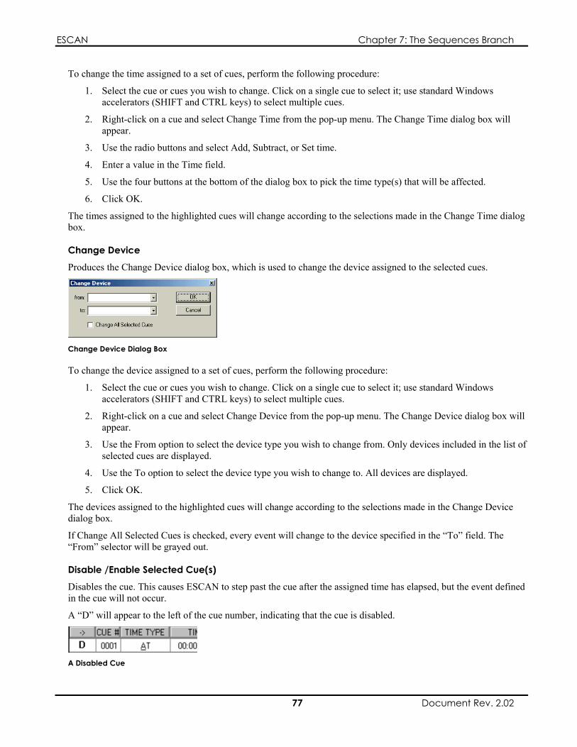
ESCAN Chapter 7: The Sequences Branch
To change the time assigned to a set of cues, perform the following procedure:
1. Select the cue or cues you wish to change. Click on a single cue to select it; use standard Windows accelerators (SHIFT and CTRL keys) to select multiple cues.
2. Right-click on a cue and select Change Time from the pop-up menu. The Change Time dialog box will appear.
3. Use the radio buttons and select Add, Subtract, or Set time.
4. Enter a value in the Time field.
5. Use the four buttons at the bottom of the dialog box to pick the time type(s) that will be affected.
6. Click OK.
The times assigned to the highlighted cues will change according to the selections made in the Change Time dialog box.
Change Device
Produces the Change Device dialog box, which is used to change the device assigned to the selected cues.
Change Device Dialog Box
To change the device assigned to a set of cues, perform the following procedure:
1. Select the cue or cues you wish to change. Click on a single cue to select it; use standard Windows accelerators (SHIFT and CTRL keys) to select multiple cues.
2. Right-click on a cue and select Change Device from the pop-up menu. The Change Device dialog box will appear.
3. Use the From option to select the device type you wish to change from. Only devices included in the list of selected cues are displayed.
4. Use the To option to select the device type you wish to change to. All devices are displayed.
5. Click OK.
The devices assigned to the highlighted cues will change according to the selections made in the Change Device dialog box.
If Change All Selected Cues is checked, every event will change to the device specified in the “To” field. The “From” selector will be grayed out.
Disable /Enable Selected Cue(s)
Disables the cue. This causes ESCAN to step past the cue after the assigned time has elapsed, but the event defined in the cue will not occur.
A “D” will appear to the left of the cue number, indicating that the cue is disabled.
A Disabled Cue
77 Document Rev. 2.02
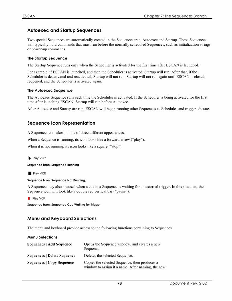
ESCAN Chapter 7: The Sequences Branch
Autoexec and Startup Sequences
Two special Sequences are automatically created in the Sequences tree; Autoexec and Startup. These Sequences will typically hold commands that must run before the normally scheduled Sequences, such as initialization strings or power-up commands.
The Startup Sequence
The Startup Sequence runs only when the Scheduler is activated for the first time after ESCAN is launched.
For example, if ESCAN is launched, and then the Scheduler is activated, Startup will run. After that, if the Scheduler is deactivated and reactivated, Startup will not run. Startup will not run again until ESCAN is closed, reopened, and the Scheduler is activated again.
The Autoexec Sequence
The Autoexec Sequence runs each time the Scheduler is activated. If the Scheduler is being activated for the first time after launching ESCAN, Startup will run before Autoexec.
After Autoexec and Startup are run, ESCAN will begin running other Sequences as Schedules and triggers dictate.
Sequence Icon Representation
A Sequence icon takes on one of three different appearances.
When a Sequence is running, its icon looks like a forward arrow (“play”).
When it is not running, its icon looks like a square (“stop”).
Sequence Icon, Sequence Running
Sequence Icon, Sequence Not Running,
A Sequence may also “pause” when a cue in a Sequence is waiting for an external trigger. In this situation, the Sequence icon will look like a double red vertical bar (“pause”).
Sequence Icon, Sequence Cue Waiting for Trigger
Menu and Keyboard Selections
The menu and keyboard provide access to the following functions pertaining to Sequences.
Menu Selections
Sequences | Add Sequence Opens the Sequence window, and creates a new Sequence.
Sequences | Delete Sequence Deletes the selected Sequence.
Sequences | Copy Sequence Copies the selected Sequence, then produces a window to assign it a name. After naming, the new
78 Document Rev. 2.02

ESCAN Chapter 7: The Sequences Branch
Sequence appears in the Workspace tree.
Sequences | Add Cue Adds a cue to the active Sequence window, above the current cue.
Sequences | Run Sequence Runs the selected Sequence. Data will only be transmitted if the Scheduler is running.
Sequences | Run from Current Position
Runs the sequence from the current cue pointer location.
Sequences | Stop Sequence Stops the selected Sequence. This option is only available when the selected Sequence is running.
Sequences | Convert Halt Until to Halt EXT
Toggles cues with Time Type Halt and Halt Until to Time Type HALT EXT.
Note
The Sequences menu is only visible when a Sequence window is active.
Keyboard Hotkeys
INS Inserts a new cue above the current cue.
DEL Deletes the current cue.
79 Document Rev. 2.02

ESCAN Chapter 7: The Sequences Branch
This page intentionally left blank.
80 Document Rev. 2.02

ESCAN Chapter 8: The Schedules Branch
Chapter 8: The Schedules Branch
Schedules Overview
A Schedule allows you to run Sequences or send individual device commands at a specific time of day, any day, or days you specify. ESCAN’s flexibility allows you to tailor your Schedules so exceptions can be made for weekends and holidays.
Schedules and Log Files
Important!
Your daily Schedule must include a cue to purge unwanted log files. If you do not do this, the hard drive can become full and crash the system.
Refer to Chapter 3, “ESCAN System Log”, for more information on Log files. Page 2 explains how to create a purge cue.
8
Schedule Priority
When activated, the Scheduler will automatically start the most specific Schedule running. For example, if it is a Wednesday, and you activate the Scheduler, ESCAN will look for the most appropriate Schedule to run using the following hierarchy:
Special Day Schedule based on that specific date. If none exist, then; Wednesday Schedule. If none exist, then; Daily Schedule
Running Individual Schedules
Since activating the Scheduler automatically starts the appropriate Schedule, it is not necessary to run an individual Schedule. It may however, be advantageous to do so for testing purposes.
If you run an individual Schedule, the currently running Schedule will stop, and the selected Schedule will run. Then, at 12:01 a.m. the next day, the Schedule you started will stop, and the next appropriate schedule will automatically run.
Chapter Structure
This chapter is divided into two sections: a how-to section describing setup procedures, and a reference section explaining the contents of menus, dialog boxes, and toolbars.
81 Document Rev. 2.02

ESCAN Chapter 8: The Schedules Branch
Schedules — How To
Accessing the Schedules Branch
The Schedules branch is the third icon displayed in the Workspace tree. If the icon is not visible, you will need to expand the current project by clicking on the plus icon next to the folder.
The Schedules Icon
Creating a Schedule
1. Right-click on the Schedules icon in the Workspace tree.
The Schedules icon
2. Click on Add Schedule from the pop-up menu that appears.
Schedule Pop-Up Menu
The Create Day Schedule dialog box will appear.
The Create Day Schedule dialog box is explained on page 8 . 6
6
3. Select the day you would like the Schedule to run, and click OK.
An icon for the Schedule will be created under the Schedules branch in the Workspace tree.
4. Double-click the new Schedule icon in the workspace tree; the Schedules window will appear.
The Schedules window is explained on page 8 .
5. Double-click on the gray line that bears the text “Double-Click or Select and Press Enter to Add New Cue.” A blank cue (Cue 0001) will appear.
6. Double-click on each of the cue’s fields and select the desired parameters.
Each cue field is explained in detail starting on page 87.
7. Repeat for as many cues as are needed.
8. Close the Schedules window.
Alternatively, you can add a Schedule by selecting Schedules | Add Schedule from the main menu.
82 Document Rev. 2.02

ESCAN Chapter 8: The Schedules Branch
Note
A Schedule called Daily is automatically created when a new ESCAN file is generated. Refer to Editing a Schedule on page 8 for information on opening existing Schedules. 3
The Schedules menu selection is only visible when an active Schedule window is visible.
Copying a Schedule
If you need to create a new Schedule that will be similar to one you already created, you may wish to copy the original Schedule, assign it a new day, and then modify its contents.
To copy a Schedule, perform the following procedure:
1. Right-click on the Schedule you wish to copy, and select Copy Schedule from the pop-up menu.
Copy Schedule Option
The Create Day Schedule dialog box will appear.
The Create Day Schedule dialog box is explained on page 86.
2. Select the day you wish the Schedule to run, and click OK.
The new Schedule will appear in the Workspace tree, containing the same cues as the Schedule you copied.
Alternatively, you can copy a Schedule by clicking on it in the Workspace tree and selecting Schedules | Copy Schedule from the main menu.
Note
The Schedules menu selection is only visible when a Schedule window is active.
Viewing/Editing a Schedule
To view a Schedule, double-click on its name in the Workspace tree.
Alternatively, right-click on it and select Edit Schedule from the pop-up menu.
Edit Schedule Option
The Schedules window will open, showing the cue list for the selected Schedule.
The cue list can now be edited or appended.
83 Document Rev. 2.02
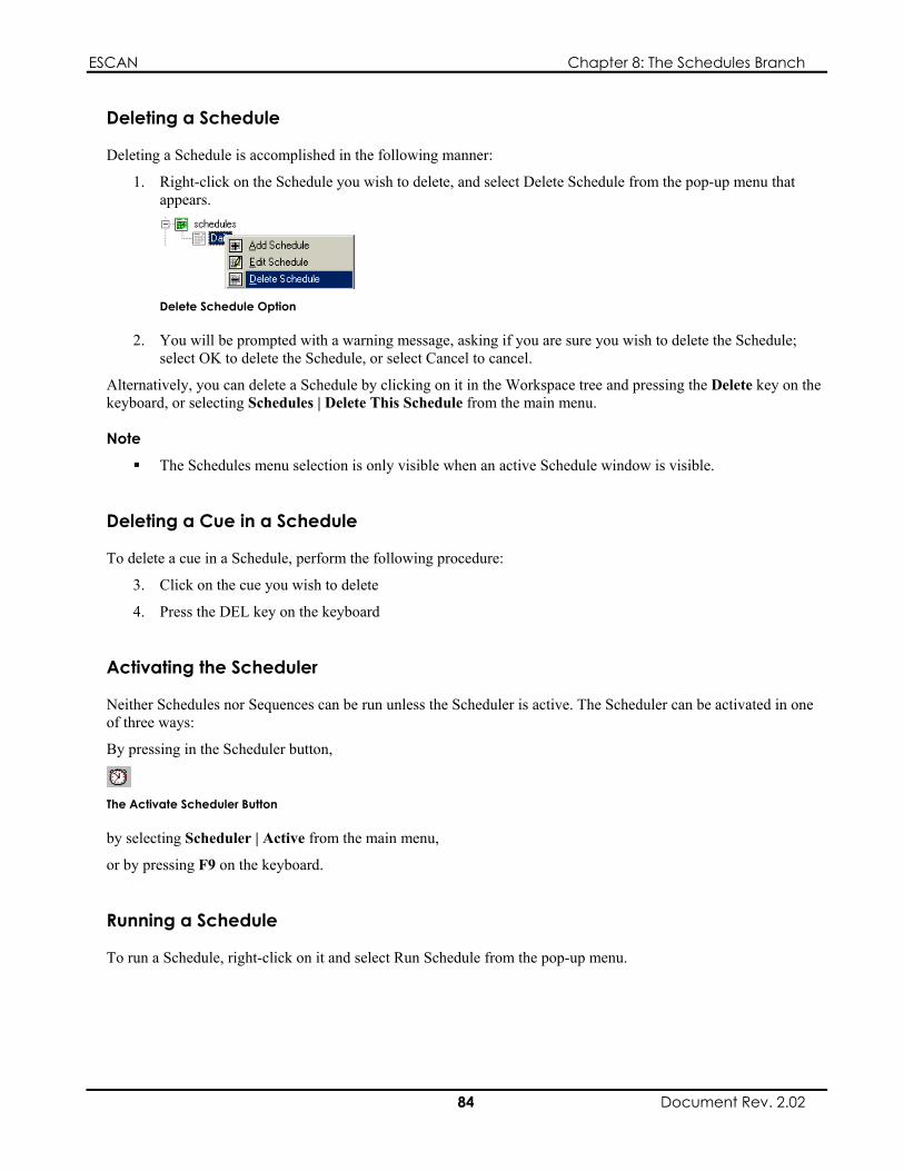
ESCAN Chapter 8: The Schedules Branch
Deleting a Schedule
Deleting a Schedule is accomplished in the following manner:
1. Right-click on the Schedule you wish to delete, and select Delete Schedule from the pop-up menu that appears.
Delete Schedule Option
2. You will be prompted with a warning message, asking if you are sure you wish to delete the Schedule; select OK to delete the Schedule, or select Cancel to cancel.
Alternatively, you can delete a Schedule by clicking on it in the Workspace tree and pressing the Delete key on the keyboard, or selecting Schedules | Delete This Schedule from the main menu.
Note
The Schedules menu selection is only visible when an active Schedule window is visible.
Deleting a Cue in a Schedule
To delete a cue in a Schedule, perform the following procedure:
3. Click on the cue you wish to delete
4. Press the DEL key on the keyboard
Activating the Scheduler
Neither Schedules nor Sequences can be run unless the Scheduler is active. The Scheduler can be activated in one of three ways:
By pressing in the Scheduler button,
The Activate Scheduler Button
by selecting Scheduler | Active from the main menu,
or by pressing F9 on the keyboard.
Running a Schedule
To run a Schedule, right-click on it and select Run Schedule from the pop-up menu.
84 Document Rev. 2.02

ESCAN Chapter 8: The Schedules Branch
Run Schedule Option
Alternatively, you can run a Schedule by selecting Schedules | Run Schedule from the main menu.
Note
If the Scheduler is not running, ESCAN will not communicate with any external devices, even though the Schedule and its associated Sequences will cycle through their cue lists.
The Schedules menu selection is only visible when an active Schedule window is visible.
Suspending a Schedule
To suspend (pause) the current, running Schedule, right-click on it and select Suspend Schedule from the pop-up menu.
Suspend Schedule Option
Alternatively, you can suspend a Schedule by selecting Schedules | Suspend Schedule from the main menu.
Note
The Suspend Schedule option is only active when the selected Schedule is running. The Schedules menu selection is only visible when a Schedule window is active.
Schedules — Reference
The Schedules Branch Menu
Right-clicking on the Schedules icon in the Workspace tree produces a pop-up menu with a single option:
Add Schedule
Schedules Pop-Up Menu
85 Document Rev. 2.02

ESCAN Chapter 8: The Schedules Branch
Add Schedule
After selecting Add Schedule, the Create Day Schedule dialog box appears.
The Create Day Schedule Dialog Box
The Create Day Schedule dialog box is used to create a new Schedule. By default, a schedule called “Daily” appears under the Schedules branch in the Workspace tree when a project is created. Actions contained within the Daily Schedule will occur every day, with no deviations.
However, if a separate Schedule is created for a specific day, ESCAN will run that Schedule as opposed to the generic Daily Schedule for that day.
For example, if a separate Schedule is created for Monday, ESCAN will run that Schedule on Mondays, and run the Daily Schedule Tuesdays through Sundays.
Create Day Schedule Dialog Box
The available Schedule options are shown below:
Schedule Type Options General Daily
Monday Tuesday Wednesday Thursday Friday Saturday Sunday
Special Day Any specific date, selected using a pop-up calendar
Note
Only one Schedule can be created per special day; e.g., only one Monday schedule, only one Schedule for May 3, 2001, etc.
After selecting the desired Schedule type and clicking OK, the new Schedule will appear under the Schedules branch in the Workspace tree.
The Schedules Window
The Schedules window allows you to create a list of events that will run the Sequences defined in your ESCAN file.
86 Document Rev. 2.02
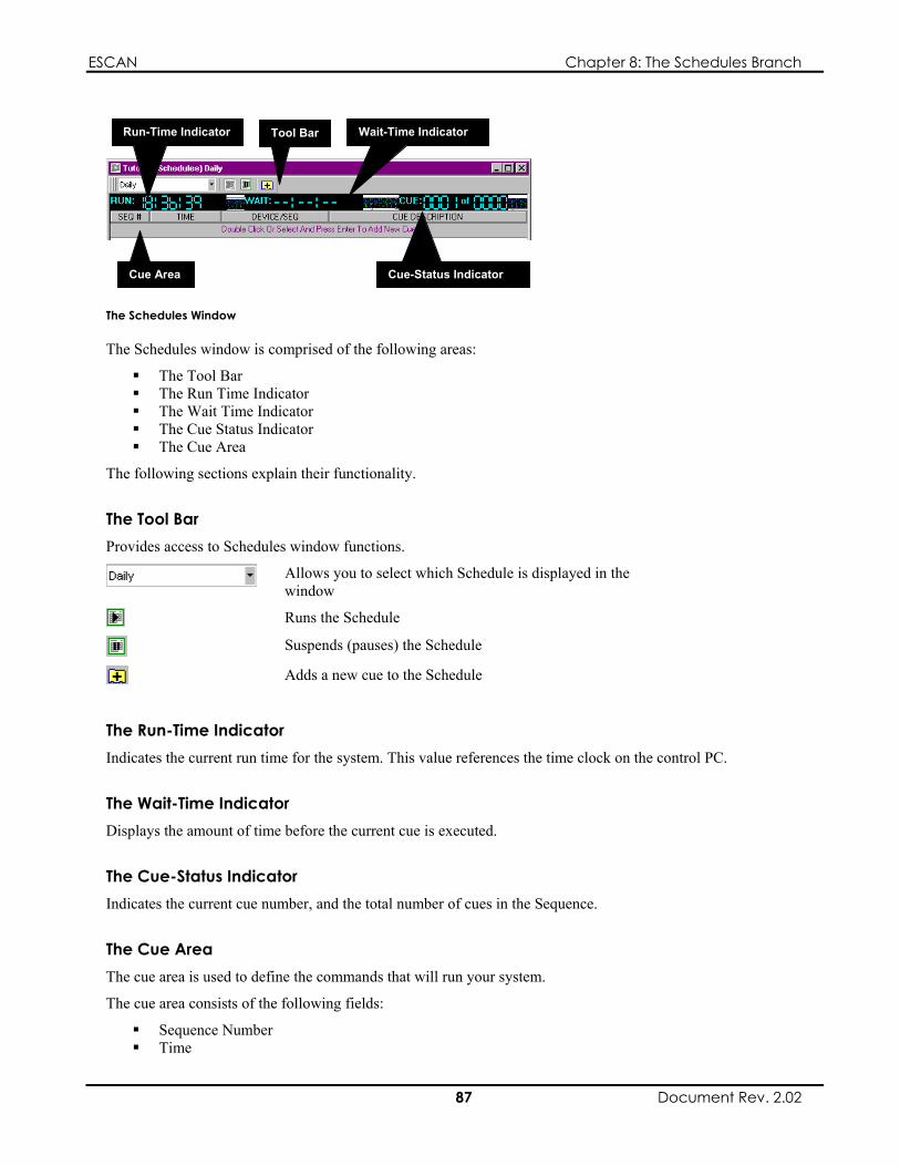
ESCAN Chapter 8: The Schedules Branch
Tool Bar Run-Time Indicator Wait-Time Indicator
Cue Area Cue-Status Indicator
The Schedules Window
The Schedules window is comprised of the following areas:
The Tool Bar The Run Time Indicator The Wait Time Indicator The Cue Status Indicator The Cue Area
The following sections explain their functionality.
The Tool Bar Provides access to Schedules window functions.
Allows you to select which Schedule is displayed in the window
Runs the Schedule
Suspends (pauses) the Schedule
Adds a new cue to the Schedule
The Run-Time Indicator Indicates the current run time for the system. This value references the time clock on the control PC.
The Wait-Time Indicator Displays the amount of time before the current cue is executed.
The Cue-Status Indicator Indicates the current cue number, and the total number of cues in the Sequence.
The Cue Area The cue area is used to define the commands that will run your system.
The cue area consists of the following fields:
Sequence Number
87 Document Rev. 2.02
Time

ESCAN Chapter 8: The Schedules Branch
Device/Sequence Cue Description
Each of these fields is explained in more detail below.
The Sequence Number Field
Indicates the cue number.
The Time Field
You will use the Time field to specify when you would like a given event to occur. Time is expressed in HH:MM:SS format, where:
HH indicates the number of hours, based on a 24-hour (military) clock.
MM indicates the number of minutes.
SS indicates the number of seconds.
Entering the Time
Double-clicking on the time field produces a slider bar interface. Click on the up and down arrows, or use the sliders to set the time.
Click Done when finished.
Click Reset to reset the time to 00:00:00.
Time Entry Sliders
The Device/Sequence Field
Double-clicking the Device/Sequence field produces a pop-up menu listing all user-defined devices, as well as Scheduler and Variables options. The value you select determines the interface that appears when the Cue Description field is double-clicked.
A Sample Device/Sequence Listing
The options and their functions are listed below:
User-Defined Devices
Select to create a cue that will control the attached device.
Scheduler Select to create a cue that will control Sequence, Schedule, and Comms events internal to ESCAN.
88 Document Rev. 2.02

ESCAN Chapter 8: The Schedules Branch
Variables Select to create a cue that will define conditional actions within ESCAN.
The Cue Description Field
The information entered in this field determines the action that occurs when the cue is released.
Double-clicking on this field produces an interface dependant on the selection in the Device/Sequence field.
If a user-defined device appears in the Device/Sequence field, a dialog box with options specific to that piece of equipment will appear.
If Scheduler appears in the Device/Sequence field, the Edit Schedule dialog box will appear. This allows you to incorporate commands that control events internal to ESCAN, such as starting and stopping Sequences, disabling comms to a device, etc. The Edit Schedule dialog box is explained in Chapter 7, “The Sequences Branch”, on page 7 . 3
If Variables appears in the Device/Sequence field, the Variables dialog box will appear. Variables are used to define conditional actions within ESCAN. Variables are explained in Chapter 10, “The Variables Branch.”
Schedule Pop-up Menu
Right-clicking on a defined Schedule in the Workspace tree produces a pop-up menu with the following options:
Add Schedule Edit Schedule Delete Schedule Copy Schedule Run Schedule Suspend Schedule
These options, explained below, let you create and edit the cues in the Schedules window.
Defined Schedule Pop-up Menu
Add Schedule
Opens the Create Day Schedule dialog box, and creates a new Schedule.
Edit Schedule
Opens a Schedule window showing the selected Schedule. Cue data can be altered to edit the Schedule.
Delete Schedule
Deletes the selected Schedule. A dialog box will appear asking if you really wish to delete the Schedule.
This option is only active when the Scheduler is not running.
89 Document Rev. 2.02

ESCAN Chapter 8: The Schedules Branch
Copy Schedule
Copies the selected Schedule, then produces the Create Daily Schedule dialog box to select the desired day. After defining the day, the new Schedule appears in the Workspace tree.
Run Schedule
Runs the selected Schedule.
Note
If the Scheduler is not running, ESCAN will not communicate with any external devices, even though the Schedule and its associated Sequences will cycle through their cue lists.
Suspend Schedule
Suspends (pauses) the selected Schedule.
This option is only active when the selected Schedule is running.
Schedules Cue Pop-Up Menu
Right-clicking on a cue line in the Schedules window produces a pop-up menu with the following options:
Schedules Cue Pop-Up Menu
Add Cue Before Selected Row
Adds a blank cue prior to the selected row.
Add Cue After Selected Row
Adds a blank cue after to the selected row.
Schedules Icon Representation
A Schedule icon takes on one of three different appearances.
When a Schedule is running, its icon contains a forward “play” arrow. When it is not running, the play arrow is not present.
Schedule Icon, Schedule Not Running
Schedule Icon, Schedule Running
If the Schedule is suspended, or paused, the icon contains a double vertical bar, or “pause” symbol.
Schedule Icon, Schedule Paused
90 Document Rev. 2.02

ESCAN Chapter 8: The Schedules Branch
Menu and Keyboard Selections: Schedules
The menu and keyboard provide access to the following functions pertaining to Schedules.
Menu Selections
Schedules | Add Schedule Opens the Schedules dialog box, and creates a new Schedule.
Schedules | Delete This Schedule
Deletes the selected Schedule.
Schedules | Copy Schedule Copies the selected Schedule, then produces a window to assign it a name. After naming, the new Sequence appears in the Workspace tree.
Schedules | Add Cue Adds a cue to the active Schedule window.
Schedules | Run Schedule Runs the selected Schedule.
Schedules | Suspend Schedule Suspends (pauses) the currently running Schedule.
Note
The Schedules menu is only visible when a Schedule window is active.
Schedules Keyboard Hotkeys
INS Inserts a new cue above the current cue.
DEL Deletes the current cue
91 Document Rev. 2.02

ESCAN Chapter 8: The Schedules Branch
This page intentionally left blank.
92 Document Rev. 2.02

ESCAN Chapter 9: The Triggers Branch
Chapter 9: The Triggers Branch
Triggers Overview
A trigger is an external command sent from an attached device to ESCAN that causes some action to be performed.
Triggers can be used in Sequences to release cues that have been assigned a time type of Halt, Halt Until, or Halt Ext. These cues can, in turn, launch the Sequences and events that correspond to the incoming triggers, as defined in Trigger Groups.
A Trigger will also perform an action defined in a Trigger Group even if it has not been assigned as a cue in a Sequence.
Triggering Devices
In order to send a trigger to ESCAN, a device capable of sending a trigger must first be defined as a device, and assigned to an available Comms port (RS-232 or Ethernet).
Not all devices are capable of sending triggers to ESCAN. Some of the more popular triggering devices are:
Electrosonic’s ES1554 MediaSonic’s VideoServer ELO Touch Screens AMX Control Equipment
A special device, called Remote Trigger, can also be defined. It allows any device capable of sending an RS-232 or Ethernet data string to pass a command to the Comms port connected to the device.
Trigger Groups
In order for a trigger to perform a function, it must first be defined in a Trigger Group. This associates the incoming command with some type of action. The action may run a Sequence, purge a log file, alter a variable value, or nearly any other function that can be performed within ESCAN.
Once a trigger has been defined, it will perform the associated action whenever the specified command is received. ESCAN can perform this action independent of any Schedules or Sequences that are running, or it can be incorporated as a cue in a Sequence that will wait for the specified trigger before proceeding (see the following section titled “Triggers to Release Cues”).
The illustration below shows a Trigger Group where the Sequence “Play VCR” will run whenever a “Show Start 3” command is received from an ES1554.
Trigger Group Showing an ES1554 Triggering a Play VCR Sequence
93 Document Rev. 2.02

ESCAN Chapter 9: The Triggers Branch
Triggers to Release Cues
In order for a Trigger to release a cue in a Sequence, the cue must have one of three time types assigned to it:
Halt Until; Halt; or, Halt EXT
Each time type is described below:
Halt Until ESCAN will release the cue when it receives the trigger specified in the Device and Cue Description fields. If the expected trigger is not received, ESCAN will proceed to the next cue when the time assigned to the cue has expired.
Halt ESCAN will release the cue when it receives the trigger specified in the Device and Cue Description fields. ESCAN will wait for the trigger indefinitely, and not proceed to the next cue until it is received.
Halt Ext ESCAN will release the cue when it receives the trigger specified in the Device and Cue Description fields. When it receives the trigger, the Time Type will switch to HALT Until, and the Time value becomes the external time value present when the trigger was received.
When ESCAN receives the trigger assigned to the cue, it will step past the cue, and proceed to the next cue in the Sequence. If an action has been assigned to the trigger in a Trigger Group, it will also perform that action when the trigger is received.
Example
The illustration below shows a Sequence containing a cue with a HALT time type. This cue will wait indefinitely for a “Show Start 3” trigger from an ES1554 before performing the action assigned in the appropriate Trigger Group.
If no action is assigned to “Show Start 3” in a Trigger Group, the trigger will simply release the cue and proceed to the next cue in the Sequence list without performing any action.
Sequence Showing a Cue Waiting for a Trigger From an ES1554
Chapter Structure
This chapter is divided into two sections: a how-to section describing setup procedures, and a reference section explaining the contents of menus, dialog boxes, and toolbars.
94 Document Rev. 2.02
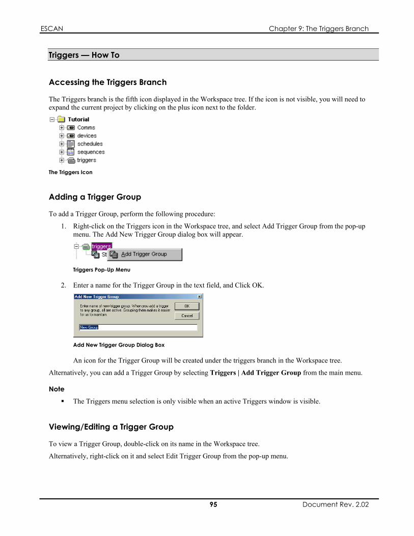
ESCAN Chapter 9: The Triggers Branch
Triggers — How To
Accessing the Triggers Branch
The Triggers branch is the fifth icon displayed in the Workspace tree. If the icon is not visible, you will need to expand the current project by clicking on the plus icon next to the folder.
The Triggers Icon
Adding a Trigger Group
To add a Trigger Group, perform the following procedure:
1. Right-click on the Triggers icon in the Workspace tree, and select Add Trigger Group from the pop-up menu. The Add New Trigger Group dialog box will appear.
Triggers Pop-Up Menu
2. Enter a name for the Trigger Group in the text field, and Click OK.
Add New Trigger Group Dialog Box
An icon for the Trigger Group will be created under the triggers branch in the Workspace tree.
Alternatively, you can add a Trigger Group by selecting Triggers | Add Trigger Group from the main menu.
Note
The Triggers menu selection is only visible when an active Triggers window is visible.
Viewing/Editing a Trigger Group
To view a Trigger Group, double-click on its name in the Workspace tree.
Alternatively, right-click on it and select Edit Trigger Group from the pop-up menu.
95 Document Rev. 2.02

ESCAN Chapter 9: The Triggers Branch
Edit Trigger Group Option
The Triggers window will open, showing the trigger list for the selected Trigger Group.
The trigger list can now be edited or appended.
Deleting a Trigger Group
Deleting a Trigger Group is accomplished in the following manner:
1. Right-click on the Trigger Group you wish to delete, and select Delete Trigger Group from the pop-up menu that appears.
Delete Trigger Group Option
2. You will be prompted with a warning message, asking if you are sure you wish to delete the Trigger Group; select Yes to delete the Trigger Group, or select No to cancel.
Alternatively, you can delete a Trigger Group by clicking on it in the Workspace tree and pressing the Delete key on the keyboard, or selecting Triggers | Delete This Trigger Group from the main menu.
Note
The Triggers menu selection is only visible when an active Triggers window is visible.
Adding a Trigger to a Trigger Group
To add a trigger to a Trigger Group, perform the following procedure:
1. Open the appropriate Trigger Group as described in the previous section.
2. Click on the Add Trigger button in the Trigger Group toolbar, or double-click on the gray line that bears the text “Double-Click or Select and Press Enter to Add New Trigger.” The Add New Trigger dialog box will appear.
The Add New Trigger dialog box is explained on page 9 . 9
3. In the Triggering Device: Device field, select the device that will be sending the Trigger to ESCAN.
4. In the Triggering Device: Trigger field, select the desired trigger that will release the action. This will be either a specific command (such as “Show Start 3”), or an integer (such as 0007), depending on the device selected in the previous step.
5. In the Triggered Device: Device field, select the device or parameter you wish the trigger to affect.
6. In the Triggered Device: Action field, select the event you wish the trigger to action. The interface for this option will vary based on the device selected in the prvious step.
7. Click Save.
96 Document Rev. 2.02

ESCAN Chapter 9: The Triggers Branch
Editing a Trigger in a Trigger Group
To Edit a trigger in a Trigger Group, perform the following procedure:
1. Open the appropriate Trigger Group as described in Viewing/Editing a Trigger Group.
2. Double-click on the trigger you wish to edit. The Add New Trigger dialog box will appear, although it will bear the name Edit Selected Trigger.
The Add New Trigger dialog box is explained on page 9 . 9
3. Edit the desired trigger parameters.
4. Click Save.
Creating a Halt Cue in a Sequence
To configure a cue in a Sequence to release upon reception of a trigger, perform the following steps.
1. Create a new Sequence, or open an existing sequence to modify.
Creating and modifying Sequences is explained in Chapter 7, “The Sequences Branch.
2. In the Sequence window, double-click on the line that bears the text “Double-Click or Select and Press Enter to Add New Cue.” A blank cue will appear.
3. Double-click on the Time Type field, and select Halt from the pop-up menu.
4. Double-click on the Device field. A list of defined devices capable of sending a trigger to ESCAN will appear. Select the desired triggering device from the list.
5. Double-click on the Cue Description field. An interface allowing the selection of a trigger specific to the device selected in the previous step will appear. Select the desired trigger.
Halt Cue Defined in a Sequence
When the selected trigger is received, the cue will release and the Sequence will continue on to the next cue. If the incoming trigger happens to be defined in a Trigger Group, the action assigned to the trigger will also be performed.
Triggers — Reference
The Triggers Branch Menu
Right-clicking on the Triggers icon in the Workspace tree produces a pop-up menu with a single option:
Add Trigger Group
Triggers Pop-Up Menu
97 Document Rev. 2.02

ESCAN Chapter 9: The Triggers Branch
Add Trigger Group
After selecting this option, the Add New Trigger Group dialog box appears, which allows you to name and create a new Trigger Group.
The Add New Trigger Group dialog box is explained in the next section.
The Add New Trigger Group Dialog Box
The Add New Trigger Group dialog box is used to create and name a new Trigger Group. After entering a name for the Trigger Group and clicking OK, the new Trigger Group will appear in the Triggers branch in the Workspace tree.
The Add New Trigger Group Dialog Box
The Triggers (Trigger Group) Window
The Triggers Window is used to define Trigger Groups. Trigger Groups act as holders for the triggers you define.
Tool BarTrigger Area
The Triggers Window
The Tool Bar
Allows you to select which Trigger Group is displayed in the window
Opens the Add New Trigger dialog box, so a new trigger can be added the Trigger Group
The Trigger Area The trigger area is used to define the triggers in your system.
Clicking anywhere on the trigger line will produce the Add New Trigger/Edit Selected Trigger dialog box which you will use to define the trigger.
The cue area consists of the following fields:
Device (Triggering) Event Triggered Device
98 Document Rev. 2.02

ESCAN Chapter 9: The Triggers Branch
Action
Each of these fields is explained in more detail below.
The Device Field
This field displays the name of the triggering device for the cue.
The triggering device is the piece of equipment sending a command to ESCAN.
The Event Field
This field displays the command that has been defined as the triggering event for the cue as sent by the triggering device. This may be a command such as “Show Start 3” sent from an ES1554, or simply an integer such as “[0003]” sent from any RS-232 or Ethernet remote controller.
The Triggered Device Field
This field displays the name of the item being controlled when the trigger is received. It can be an attached device, or a Schedule or Variable command.
The Action Field
The Action field displays what will happen when the trigger is received.
The Add New Trigger/Edit Selected Trigger Dialog Box
This dialog box is used to define a trigger within a Trigger Group. If accessed when defining a new trigger, it will bear the name “Add New Trigger.” If it appears when editing a trigger, it will bear the name “Edit Selected Trigger.”
The Add New Trigger Dialog Box
Triggering Device Region
Device
Use this field to choose which device will send the trigger to ESCAN.
The items selected in this field will be displayed in the Device field in the Trigger Group’s trigger listing.
Trigger
Use this field to select the command that will serve as the trigger. The interface for this field will vary, based on the device selected in the field above.
The value selected in this field will be displayed in the Event field in the Trigger Group’s trigger listing.
99 Document Rev. 2.02

ESCAN Chapter 9: The Triggers Branch
Triggered Device Region
Device
Use the Device drop-down list to select which function will be affected by the incoming trigger.
The options are listed below:
User-defined Devices
Select to create a cue that will control an attached device.
Scheduler Select to create a cue that will control Sequence, Schedule, and comms events internal to ESCAN.
Variables Select to create a cue that will define conditional actions within ESCAN. Refer to Chapter 10, “The Variables Branch”, for more information about variables.
The items selected in this field will be displayed in the Triggered Device field in the Trigger Group’s trigger listing.
Action
Clicking on the button next to the Action field will produce a dialog box specific to the device selected in the field above. From this dialog box, you will select the action you wish the incoming trigger to initiate.
The items selected in this field will be displayed in the Action field in the Trigger Group’s trigger listing.
Trigger Parameter Mapping The illustration below shows how the parameters selected in the Edit Selected Trigger dialog box map to a trigger in a Trigger Group.
Parameter Mapping to Trigger Group Entry
The Trigger Group Pop-Up Menu
Right-clicking on a Trigger Group in the Workspace tree produces a pop-up menu with the following options:
Edit Trigger Group Delete Trigger Group Rename
These options, explained below, let you modify the selected Trigger Group.
100 Document Rev. 2.02
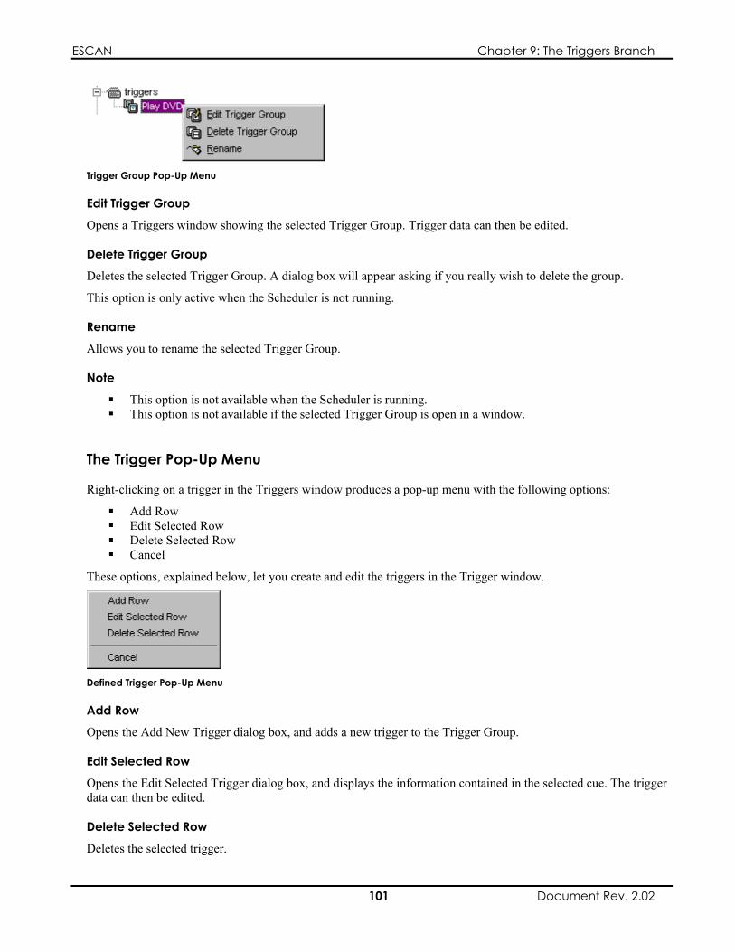
ESCAN Chapter 9: The Triggers Branch
Trigger Group Pop-Up Menu
Edit Trigger Group
Opens a Triggers window showing the selected Trigger Group. Trigger data can then be edited.
Delete Trigger Group
Deletes the selected Trigger Group. A dialog box will appear asking if you really wish to delete the group.
This option is only active when the Scheduler is not running.
Rename
Allows you to rename the selected Trigger Group.
Note
This option is not available when the Scheduler is running. This option is not available if the selected Trigger Group is open in a window.
The Trigger Pop-Up Menu
Right-clicking on a trigger in the Triggers window produces a pop-up menu with the following options:
Add Row Edit Selected Row Delete Selected Row Cancel
These options, explained below, let you create and edit the triggers in the Trigger window.
Defined Trigger Pop-Up Menu
Add Row
Opens the Add New Trigger dialog box, and adds a new trigger to the Trigger Group.
Edit Selected Row
Opens the Edit Selected Trigger dialog box, and displays the information contained in the selected cue. The trigger data can then be edited.
Delete Selected Row
Deletes the selected trigger.
101 Document Rev. 2.02

ESCAN Chapter 9: The Triggers Branch
Cancel
Closes the pop-up menu.
Menu Selections
Triggers | Add Trigger Group Opens the Add New Trigger Group dialog box, and creates a new Trigger Group.
Triggers | Delete This Trigger Group
Deletes the selected Trigger Group.
Note
The Triggers menu is only visible when a Triggers (Trigger Group) window is active.
Closing Notes
Here are a few final points to keep in mind when using triggers:
Valid Trigger numbers for the Remote Trigger device are 0000 through 9998. 9999 is a reserved trigger and should not be used
It is not recommended to use an IP port setting of 23 with MS VideoServers if you will be receiving triggers from them.
102 Document Rev. 2.02
ESCAN Chapter 10: The Variables Branch
Chapter 10: The Variables Branch
Variables Overview
A variable is a conditional statement that affects the way in which ESCAN performs its functions. Variables are defined and held in Variable Groups, where they are later referenced from cues within a defined Sequence, Schedule, or from a Trigger.
Variables are an extremely powerful feature of ESCAN, and it would be impossible to describe every aspect of their use. This chapter will cover the basics of variables, and discusses two scenarios that utilize them:
Setting a Sequence to Loop 5 times Using a Device Property to perform video switch
Using Variables
There are five techniques used when working with variables:
Creating Variable Groups Defining Global variables Setting variable values Comparing variables Using Device Property variables
These techniques are explained below.
Creating Variable Groups
Before defining a variable, you must first create a Variable Group in which to place it. Variable Groups are created and listed in the Workspace tree.
Defining Variables
After creating a Variable Group, you can define its variable(s). This tells ESCAN what kind of variable it is, and makes it available for initialization (see Setting Variable Values below).
Setting Variable Values
After defining a variable, you must set its initial value. This is called initializing the variable, and is done in the Change tab of the Edit Variable Cue dialog box.
The Edit Variable Cue dialog box is explained on page 122.
Comparing Variables
A basic function of variable use involves comparing its current value to that of another variable, or to some other predetermined value. An if – then statement based on the comparison can then cause a specific event to occur within ESCAN. Variable comparisons are performed in the Test tab of the Edit Variables Cue dialog box.
The Edit Variable Cue dialog box is explained on page 12 . 2
103 Document Rev. 2.02
ESCAN Chapter 10: The Variables Branch
Using Device Property Variables
Variables can alter the parameters of certain devices. One example of this is the input and an output parameter value of an Autopatch switcher. Device Properties are manipulated using both the Change and Test tabs of the Edit Variable Cue dialog box.
The Edit Variable Cue dialog box is explained on page 122.
Chapter Structure
This chapter is divided into three sections: a tutorial section which walks you through basic variable use, a how-to section describing setup procedures, and a reference section explaining the contents of menus, dialog boxes, and toolbars.
Variables — Tutorials
Variable Tutorial #1: Creating a Loop Counter
This tutorial shows how to use variables to cause a series of cues to execute a fixed number of times.
This exercise will teach you four of the five techniques of variable use:
Creating a Variable Group Defining global variables Setting variable values Comparing variables
Note
This chapter assumes a level of familiarity with most of ESCAN’s functions, as described in Chapters 5 through 9.
Creating a New File Create a new file by clicking on the New File button, or selecting File | New from the top line menu.
ESCAN’s New File Button
A new, empty file called “Untitled1.ess” (or similar name) will be created.
Saving the File Before getting started, you should save the file.
To save the file, click on ESCAN’s Save button, or select File | Save As… from the top line menu.
ESCAN’s Save Button
Windows’ Save As dialog box will appear. Assign the name “LoopCountTutorial” to the file, and click Save.
104 Document Rev. 2.02

ESCAN Chapter 10: The Variables Branch
Setting the System’s Frame Rate Set the system’s frame rate to the appropriate setting for you locale.
For more information on setting the system’s frame rate, refer to page 32.
Creating a Variable Group 1. Right-click on the Variables icon in the Workspace tree, and select Add Variable Group from the pop-up
menu. The Add New Variable Group dialog box will appear.
Variables Pop-Up Menu
2. Enter the name “Loop Counter” in the text field, and Click OK.
Add New Variable Group Dialog Box
An icon for the Variable Group will be created under the variables branch in the Workspace tree.
3. Double-click the new Variable Group icon in the workspace tree; the variables window will appear showing the empty Variable Group “Loop Counter.”
Defining a Global Variable 1. Click on the Add Variable button in the Variable Group toolbar, or double-click on the gray line that bears
the text “Double-Click or Select and Press Enter to Add New cue.” The Define Variable dialog box will appear.
The Define Variables dialog box is explained on page 121.
2. In the Type field, select “int.” This defines the variable as an integer.
3. In the Name field, enter the name “Loop Count.”
Defining the Variable “Loop Count”
4. Click Add. The new variable will now appear in the Variable Group window.
Loop Count Variable Defined in Variable Group “Loop Counter”
105 Document Rev. 2.02

ESCAN Chapter 10: The Variables Branch
Setting the Variable’s Value (“Initializing” the Variable) 1. Create a new Sequence called “Start Loop.”
2. Open the Start Loop Sequence.
3. Double-click on the gray line that bears the text “Double-Click or Select and Press Enter to Add New Cue.” A blank cue (Cue 0001) will appear.
4. Double-click on the Time Type field, and select Wait from the pop-up menu.
5. Leave the Time field set to 00:00:00.00.
6. Double-click on the Device field, and select Variables from the pop-up list.
7. Double-click on the Cue Description field. The Edit Variables Cue dialog box will appear.
The Edit Variables Cue dialog box is explained on page 122.
8. Click on the Change tab.
9. In the Set region, click on the Variables radio button.
Note
The radio buttons in this region will appear greyed out unless a variable has been defined in a Variable group and a Device capable of being controlled by variables has been created. In this example, the radio button “Variable” will be permanently selected.
10. Still in Set region, select Loop Count from the active drop-down list.
11. From the drop-down list between the Set region and the Operand region, select “assign (=).”
12. In the Operand region, click on the Value radio button.
13. In the active text field (Value), enter “0.” The Edit Variables dialog box should look like the one shown below:
Loop Count Variable Initialized With Value of 0
Click OK.
14. Create a new Sequence called “Looping Sequence.”
15. Open Looping Sequence.
106 Document Rev. 2.02

ESCAN Chapter 10: The Variables Branch
16. Double-click on the gray line that bears the text “Double-Click or Select and Press Enter to Add New Cue.” A blank cue (Cue 0001) will appear.
17. Double-click on the Time Type field, and select Wait from the pop-up menu.
18. Leave the Time field set to 00:00:00.00.
19. Double-click on the Device field, and select Variables from the pop-up list.
20. Double-click on the Cue Description field. The Edit Variables Cue dialog box will appear.
21. Click on the Change tab.
22. In the Set region, make sure the Variables radio button is selected.
23. Still in Set region, select Loop Count from the active drop-down list.
24. From the drop-down list between the Set region and the Operand region, select “add 1 (++).” The Edit Variables dialog box should look like the one shown below. Click OK.
Loop Count Variable Set to Increment by 1
25. Add a new cue to Looping Sequence.
26. Double-click on the Time Type field, and select Wait from the pop-up menu.
27. Set the Time field set to 00:00:01.00.
28. Double-click on the Device field, and select Scheduler from the pop-up list.
29. Double-click on the Cue Description field. The Edit Schedule Cue dialog box will appear. Select NO-OP from the Command drop-down list.
30. In the Comment field, type “Ran Looping Sequence.” The dialog box should look like the example below:
Defined NO-OP Cue
Click OK.
107 Document Rev. 2.02

ESCAN Chapter 10: The Variables Branch
Comparing the Variable’s Value 1. Add a new cue to Looping Sequence.
2. Double-click on the Time Type field, and select Wait from the pop-up menu.
3. Set the Time field to 00:00:01.00.
4. Double-click on the Device field, and select Variables from the pop-up list.
5. Double-click on the Cue Description field. The Edit Variables Cue dialog box will appear.
6. Click on the Test tab.
7. In the IF region, click on the Variables radio button.
Note
The radio buttons in this region will appear greyed out unless a variable has been defined in a Variable group and a Device capable of being controlled by variables has been created. In this example, the radio button “Variable” will be permanently selected.
8. Still in IF region, select Loop Count from the active drop-down list.
9. From the drop-down list between the Set region and the Operand region, select “is less than (<).”
10. In the Operand region, click on the Value radio button.
11. Still in the Operand region, enter “5” in the active text field.
12. In the Device to Control region, select Scheduler from the drop-down list.
13. Click on the button below the drop-down list. The Edit Schedule Cue dialog box will appear. Select Run Sequence from the Command drop-down list.
14. Select “Looping Sequence” from the Control drop-down list. The dialog box should look like the example below:
Looping Sequence Selected to Run
Click OK.
15. The Edit Variables dialog box should look like the one shown below:
108 Document Rev. 2.02

ESCAN Chapter 10: The Variables Branch
Correct Variable Comparison Settings
Click OK.
Creating the Last Cue 1. Add a new cue to the Start Loop Sequence (the first Sequence created in this tutorial).
2. Double-click on the Time Type field, and select Wait from the pop-up menu.
3. Set the Time field to 00:00:01.00.
4. Double-click on the Device field, and select Scheduler from the pop-up list.
5. Double-click on the Cue Description field. The Edit Schedule Cue dialog box will appear. Select Run Sequence from the Command drop-down list.
6. Select “Looping Sequence” from the Control drop-down list. The dialog box should look like the example below:
Looping Sequence Selected to Run
Click OK.
The completed cue listings are shown below:
Completed Looping Sequence Sequence
Completed Start Loop Sequence
109 Document Rev. 2.02

ESCAN Chapter 10: The Variables Branch
Testing the Loop Make sure the Scheduler is active, and run the Sequence called Start Loop. When finished, the log window should look like the following example:
Log Window Showing Loop Results
The NO-OP comment you created should appear in the list five times.
What You’ve Learned In this tutorial, you learned how to create a Variable Group, define a global variable, initialize a variable, and compare a variable’s value in order to affect events within ESCAN.
The next tutorial covers Device Property variables, the last of the five techniques mentioned on page 103..
Variable Tutorial #2: Device Properties
Variables can be used in conjunction with triggers to set control parameters for certain devices. The following tutorial shows how an AMX touch panel can control an Autopatch switcher through ESCAN. It does this by sending a serial string to the ESCAN PC, which has been configured to receive a trigger from the AMX device. The incoming trigger data is processed as variables that define the input and output parameters for the switcher.
For the purpose of this tutorial, it is not necessary to have an AMX controller or an Autopatch switcher. It is more important that you learn the processes involved in configuring and integrating the various system elements required for this exercise.
Note
This chapter assumes a level of familiarity with most of ESCAN’s functions, as described in Chapters 5 through 9.
Creating a New File. Create a new file by clicking on the New File button, or selecting File | New from the top line menu.
ESCAN’s New File Button
A new, empty file called “Untitled1.ess” (or similar name) will be created.
110 Document Rev. 2.02

ESCAN Chapter 10: The Variables Branch
Saving the File. Before getting started, you should save the file.
To save the file, click on ESCAN’s Save button, or select File | Save As… from the top line menu.
ESCAN’s Save Button
Windows’ Save As dialog box will appear. Assign the name “DevicePropertiesTutorial” to the file, and click Save.
Setting the System’s Frame Rate. Set the system’s frame rate to the appropriate setting for you locale.
For more information on setting the system’s frame rate, refer to page 3 . 2
Comms Port Definition. Define two RS-232 Comms ports; one for an AMX touch panel, and one for an Autopatch switcher. While it is technically not necessary to configure the Comms ports for the tutorial, it will more closely simulate the work flow were this an actual control system.
AMX and Autopatch Port Definitions
Device Definition.
Defining the AMX Device
1. Right-click on the Devices icon in the Workspace tree.
The Devices Icon
2. Click on Add Device from the pop-up menu that appears.
Device Pop-Up Menu
The Add Device dialog box will appear
3. From the Device Type drop-down list, select “Panja-AMX.”
4. In the Device Name field, type “Panja-AMX.”
5. Make sure the dialog box looks like the example shown below, and then click the OK button.
111 Document Rev. 2.02
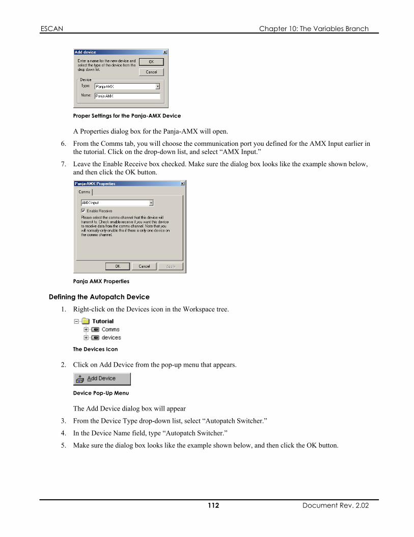
ESCAN Chapter 10: The Variables Branch
Proper Settings for the Panja-AMX Device
A Properties dialog box for the Panja-AMX will open.
6. From the Comms tab, you will choose the communication port you defined for the AMX Input earlier in the tutorial. Click on the drop-down list, and select “AMX Input.”
7. Leave the Enable Receive box checked. Make sure the dialog box looks like the example shown below, and then click the OK button.
Panja AMX Properties
Defining the Autopatch Device
1. Right-click on the Devices icon in the Workspace tree.
The Devices Icon
2. Click on Add Device from the pop-up menu that appears.
Device Pop-Up Menu
The Add Device dialog box will appear
3. From the Device Type drop-down list, select “Autopatch Switcher.”
4. In the Device Name field, type “Autopatch Switcher.”
5. Make sure the dialog box looks like the example shown below, and then click the OK button.
112 Document Rev. 2.02

ESCAN Chapter 10: The Variables Branch
Proper Settings for the Autopatch Switcher Device
A Properties dialog box for the Autopatch switcher will open.
6. From the Comms tab, you will choose the communication port you defined for the Autpoatch Switcher earlier in the tutorial. Click on the drop-down list, and choose “Autopatch Control.”
7. Leave the Enable Receive box checked.
8. Switch to the Levels tab, and type “Level 1” in the Name field
9. Click on the Add Next button.
10. Make sure the dialog box looks like the example shown below, and then click the OK button.
Autopatch Switcher Properties
Creating the AMX Handler Sequence. Create a new Sequence, and call it “AMX Handler.”
You will not insert any cues in the Sequence at this time.
Create the AMX Trigger Group .
Creating the Trigger Group and Trigger
1. Create a new Trigger Group, and call it “AMX Trigger.”
2. Open the AMX Trigger Trigger Group.
3. Click on the Add Trigger button in the Trigger Group toolbar, or double-click on the gray line that bears the text “Double-Click or Select and Press Enter to Add New Trigger.” The Add New trigger dialog box will appear.
113 Document Rev. 2.02
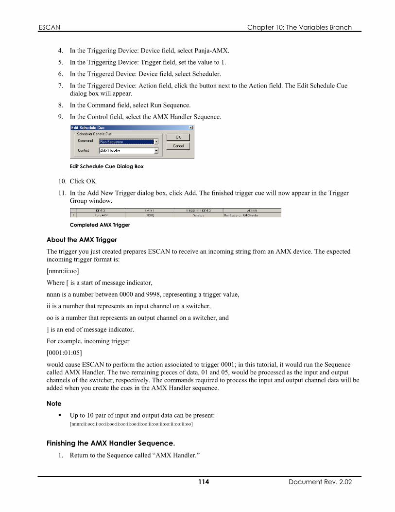
ESCAN Chapter 10: The Variables Branch
4. In the Triggering Device: Device field, select Panja-AMX.
5. In the Triggering Device: Trigger field, set the value to 1.
6. In the Triggered Device: Device field, select Scheduler.
7. In the Triggered Device: Action field, click the button next to the Action field. The Edit Schedule Cue dialog box will appear.
8. In the Command field, select Run Sequence.
9. In the Control field, select the AMX Handler Sequence.
Edit Schedule Cue Dialog Box
10. Click OK.
11. In the Add New Trigger dialog box, click Add. The finished trigger cue will now appear in the Trigger Group window.
Completed AMX Trigger
About the AMX Trigger
The trigger you just created prepares ESCAN to receive an incoming string from an AMX device. The expected incoming trigger format is:
[nnnn:ii:oo]
Where [ is a start of message indicator,
nnnn is a number between 0000 and 9998, representing a trigger value,
ii is a number that represents an input channel on a switcher,
oo is a number that represents an output channel on a switcher, and
] is an end of message indicator.
For example, incoming trigger
[0001:01:05]
Note
Up to 10 pair of input and output data can be present: [nnnn:ii:oo:ii:oo:ii:oo:ii:oo:ii:oo:ii:oo:ii:oo:ii:oo:ii:oo:ii:oo]
Finishing the AMX Handler Sequence.
would cause ESCAN to perform the action associated to trigger 0001; in this tutorial, it would run the Sequence called AMX Handler. The two remaining pieces of data, 01 and 05, would be processed as the input and output channels of the switcher, respectively. The commands required to process the input and output channel data will be added when you create the cues in the AMX Handler sequence.
1. Return to the Sequence called “AMX Handler.”
114 Document Rev. 2.02

ESCAN Chapter 10: The Variables Branch
2. Double-click on the gray line that bears the text “Double-Click or Select and Press Enter to Add New Cue.” A blank cue (Cue 0001) will appear.
3. Double-click on the Time Type field, and select Wait from the pop-up menu.
4. Leave the Time field set to 00:00:00.00.
5. Double-click on the Device field, and select Variables from the pop-up list.
6. Double-click on the Cue Description field. The Edit Variables Cue dialog box will appear.
The Edit Variables Cue dialog box is explained on page 12 . 2
7. Click on the Change tab.
8. In the Set region, click on the Device Property radio button.
Note
The radio buttons in this region will appear greyed out unless a variable has been defined in a Variable group and a Device capable of being controlled by variables has been created. In this example, the radio button “Device Property” will be permanently selected.
9. Still in Set region, select Autopatch Switcher from the upper drop-down list, and select Input from the lower drop-down list.
10. In the drop-down list between the Set region and the Operand region, select “assign (=).”
11. In the Operand region, click on the Device Property radio button.
12. Still in Operand region, select Panja-AMX from the upper drop-down list, and select InParam 1 from the lower drop-down list. The Edit Variables dialog box should look like the following example:
Autopatch Input Parameters
Click OK.
13. Add a new cue to the Sequence.
14. Double-click on the Time Type field, and select Wait from the pop-up menu.
15. Set the value in the Time field to 00:00:00.05.
16. Double-click on the Device field, and select Variables from the pop-up list.
17. Double-click on the Cue Description field. The Edit Variables Cue dialog box will appear.
115 Document Rev. 2.02

ESCAN Chapter 10: The Variables Branch
18. Click on the Change tab.
19. In the Set region, click on the Device Property radio button.
20. Still in Set region, select Autopatch Switcher from the upper drop-down list, and select Output from the lower drop-down list.
23. Still in Operand region, select Panja-AMX from the upper drop-down list, and select OutParam 1 from the lower drop-down list. The Edit Variables dialog box should look like the one shown below:
21. In the drop-down list between the Set region and the Operand region, select “assign (=).”
22. In the Operand region, click on the Device Property radio button.
Autopatch Output Parameters
Click OK.
24. Add a new cue to the Sequence.
27. Double-click on the Device field, and select Autopatch Switcher from the pop-up list.
30. Select Level 1 in the Level field, and click OK.
25. Double-click on the Time Type field, and select Wait from the pop-up menu.
26. Set the value in the Time field to 00:00:00.05.
28. Double-click on the Cue Description field. The Edit Crosspoint Cue dialog box will appear.
29. Select Set Crosspoint from Variables in the Cue Type field.
Autopatch Crosspoint Parameters
31. Add a new cue to the Sequence.
32. Double-click on the Time Type field, and select Wait from the pop-up menu.
33. Set the value in the Time field to 00:00:00.05.
116 Document Rev. 2.02

ESCAN Chapter 10: The Variables Branch
34. Double-click on the Device field, and select Panja-AMX from the pop-up list.
35. Double-click on the Cue Description field. The Select Panja-AMX Cue dialog box will appear.
36. Click on the Enable Next Trigger radio button.
Panja-AMX Cue Parameters
37. Click OK.
The finished Sequence cue listing should now look like this:
AMX Handler Cue Listing
What You’ve Learned In this tutorial, you created a Sequence that utilizes data from an external trigger to manipulate the Device Properties of an Autopatch switcher.
The trigger you defined in the Trigger Group readies ESCAN to receive an incoming signal from the AMX device. Let’s assume the incoming trigger is:
0001:01:05
The AMX Handler Sequence processes the incoming trigger data and switches the Autopatch switcher to the specified input and output. Cue breakdown is as follows:
Cue 0001 grabs the first piece of information following the initial trigger value, which ESCAN refers to as “InParam 1.” Given the trigger value shown above, the value processed is “01.”
Cue 0002 grabs the second piece of information following the initial trigger value, which ESCAN refers to as “OutParam 1.” Given the trigger value shown above, the value processed is “05.”
Cue 0003 tells the Autopatch switcher to perform a Level 1 switch based on the values processed by the variables in cues 0001 and 0002.
Cue 0004 readies ESCAN to process the next variable pair in the incoming trigger, if it exists .
Variables — How To
Accessing the Variables Branch
The Variables branch is the last icon displayed in the Workspace tree. If the icon is not visible, you will need to expand the current project by clicking on the plus icon next to the folder.
117 Document Rev. 2.02
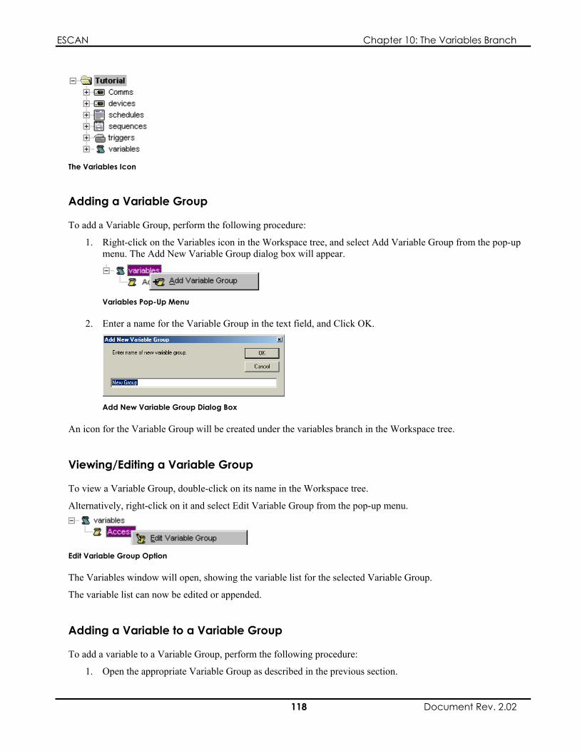
ESCAN Chapter 10: The Variables Branch
The Variables Icon
Adding a Variable Group
To add a Variable Group, perform the following procedure:
1. Right-click on the Variables icon in the Workspace tree, and select Add Variable Group from the pop-up menu. The Add New Variable Group dialog box will appear.
Variables Pop-Up Menu
2. Enter a name for the Variable Group in the text field, and Click OK.
Add New Variable Group Dialog Box
An icon for the Variable Group will be created under the variables branch in the Workspace tree.
Viewing/Editing a Variable Group
To view a Variable Group, double-click on its name in the Workspace tree.
Alternatively, right-click on it and select Edit Variable Group from the pop-up menu.
Edit Variable Group Option
The Variables window will open, showing the variable list for the selected Variable Group.
The variable list can now be edited or appended.
Adding a Variable to a Variable Group
To add a variable to a Variable Group, perform the following procedure:
1. Open the appropriate Variable Group as described in the previous section.
118 Document Rev. 2.02

ESCAN Chapter 10: The Variables Branch
2. Click on the Add Variable button in the Variable Group toolbar, or double-click on the line that bears the text “Double-Click or Select and Press Enter to Add New cue.” The Define Variable dialog box will appear.
The Define Variables dialog box is explained on page . 121
121
3. In the Type field, select the type of variable you are defining.
4. In the Name field, enter a unique name for the variable.
5. Click Save.
The new variable will now appear in the Variable Group window.
Editing a Variable in a Variable Group
To Edit a variable in a Variable Group, perform the following procedure:
1. Open the appropriate Variable Group as described in Viewing/Editing a Variable Group.
2. Double-click on the variable you wish to edit. The Define Variable dialog box will appear.
The Define Variables dialog box is explained on page .
3. Edit the desired variable parameters.
4. Click Save.
Variables — Reference
The Variables Branch Menu
Right-clicking on the Variables icon in the Workspace tree produces a pop-up menu with a single option:
Add Variable Group
Variables Pop-Up Menu
Add Variable Group
After selecting this option, the Add New Variable Group dialog box appears, which allows you to name and create a new Variable Group.
The Add New Variable Group Dialog Box
The Add New Variable Group dialog box is used to create and name a new Variable Group. After entering a name and clicking OK, the new Variable Group will appear in the Variables branch in the Workspace tree, and a new Variable Group window will appear.
119 Document Rev. 2.02

ESCAN Chapter 10: The Variables Branch
The Add New Variable Group Dialog Box
The Variables (Variable Group) Window
The Variables window allows you to create a list of variables that can later be referenced from cues in the Sequence or Schedule windows.
Tool BarVariables Area
The Variables Window
The Tool Bar Allows you to select which variable group is displayed in the window
Opens the Define Variable dialog box, and adds a new variable to the variable group
The Variables Area The variables area displays the variables that have been defined within the Variable Group.
Double-clicking on the last line in the window will open the Define Variables dialog box, which is used to create a new variable.
Double-clicking on an existing variable will also open the Define Variables dialog box, which can then be used to change the parameters of the selected variable.
The Define Variables dialog box is explained below.
The Type Field
Displays the type of variable: Boolean, date, integer, or string.
The Variable Name Field
Displays the name of the variable.
120 Document Rev. 2.02

ESCAN Chapter 10: The Variables Branch
The Define Variable Dialog Box
The Define Variable dialog box is used to create a new variable within a Variable Group.
The Define Variable Dialog Box
The Type Field
Use this field to select what type of variable you are defining.
The table below shows the available options:
Variable Type Function boolean A variable dependent on an IF/THEN status that is looked at
before a sequence will run date A variable that is date dependent int A variable based on an integer, such as a counter
A variable that is based on a text string string
The Name Field
Use this field to assign a unique name to the variable you are defining.
The Variable Group Pop-Up Menu
Right-clicking on a Variable Group in the Workspace tree produces a pop-up menu with the following options:
Edit Variable Group Delete Variable Group Rename
These options, explained below, let you modify the selected Variable Group.
The Variable Group Pop-Up Menu
Edit Variable Group
Opens a Variables window showing the selected variable group. Variable data can then be viewed or edited.
Delete Variable Group
Deletes the selected variable group. A dialog box will appear asking if you really wish to delete the group.
This option is only active when the Scheduler is not running.
121 Document Rev. 2.02

ESCAN Chapter 10: The Variables Branch
Rename
Allows you to rename the selected variable group.
Note
This option is not available when the Scheduler is running.
The Variable Pop-Up Menu
Right-clicking on a variable in the Variables window produces a pop-up menu with the following options:
Add Row Edit Selected Row Delete Selected Row Cancel
These options, explained below, let you modify the selected variable.
Defined Variable Pop-Up Menu
Add Row
Opens the Define Variable dialog box, and adds a new variable to the variable group.
Edit Selected Row
Opens the Define Variable dialog box, so the selected variable can be edited.
Delete Selected Row
Deletes the selected variable.
Cancel
Closes the pop-up menu.
Edit Variables Cue Dialog Box
The Edit Variables dialog box is used to define, alter, and compare variable values, and manipulate Device Properties.
It appears when defining the Cue Description field of a Sequence or Schedule when Variable is set in the Device Sequence field.
Change Tab The Change tab is used to set or alter the value of a variable or device property. It is comprised of the following regions:
122 Document Rev. 2.02

ESCAN Chapter 10: The Variables Branch
Set Operand
A selector is also present, positioned between the two regions.
The options selected in the Change tab build an “equation” that lets you define or alter a variable or device property:
[ Set option ] {Operator} [ Operand option ]
For example:
[ Variable “Loop Count” ] { = } [ 0 ]
Note
The Operand option may be unavailable, depending on the selected Set option and Operator.
Change Tab
The Set Region The Set region allows you to select either a variable or Device Property to define or alter.
Variable
Choosing the Variable radio button activates its corresponding selector, which displays all of the variables defined in the current file’s variable groups.
Device Property
Choosing the Device Property radio button activates its two corresponding selectors.
The upper selector displays a list of the currently defined devices that can be affected by the Variables function.
The lower selector displays a list of parameters relative to the device selected in the previous field.
Note
The radio buttons in this region will appear greyed out unless a variable has been defined in a Variable group and a Device capable of being controlled by variables has been created. In this example, the radio button “Device Property” will be permanently selected.
123 Document Rev. 2.02

ESCAN Chapter 10: The Variables Branch
The Operator Selector Positioned between the two regions is a selector used to choose an operator. The chosen operator determines what function is performed between the items selected in the Set and Operand regions.
The available options are determined by the type of variable selected in the Variable field, or by the expected Device Property data.
Variable Type Available Operands assign ( = ) Boolean invert ( ! ) assign ( = ) add ( + ) subtract ( - ) add 1 ( ++ )
Date
subtract ( - ) multiply ( * )
Int
clear assign ( = ) concatenate ( & )
string
clear
subtract 1 ( -- ) assign ( = ) add ( + )
divide (/) modulus [remainder] ( % ) add 1 ( ++ ) subtract 1 ( -- ) percent
The Operand Region The Operand region allows you to select either a Variable, Device Property, or Value as the operand.
Note
This region may be disabled, depending on the options selected in the Set and Operator fields.
Device Property
The lower selector displays a list of parameters relative to the device selected in the field above.
Value
The type of value that you can enter is determined by the type of variable you are modifying.
Variable
Choosing the Variable radio button activates its corresponding selector, which displays all of the variables defined in the current file’s variable groups. Note that if a variable was selected in the Set region, it will not appear in the list.
Choosing the Device Property radio button activates its two corresponding selectors.
The upper selector displays a list of the currently defined devices that can be affected by the Variables function.
Choosing the Value radio button allows you to define a value for the Operand.
Variable Type Permissible Value boolean True or false, entered using the displayed selector
124 Document Rev. 2.02
date A date, selected using a pop-up calendar interface

ESCAN Chapter 10: The Variables Branch
Variable Type Permissible Value int An integer, entered by typing the value in the text
box string A text string, entered by typing it in the text box
Note
The data entered in the Value field must be less that 1,000 characters in length.
Test Tab The test tab is used to create conditional statements that affect the actions ESCAN performs. It is comprised of the following regions:
If Operand Device to Control
A selector is also present, positioned between the If and Operand regions.
The options selected in the Test tab build an if/then statement that, in turn, causes an event to happen in ESCAN. This may be an internal event, or it may be an event that sends a command to a device.
If [If option ] {Operator} [ Operand option ] Then [ Device to Control option ]
For example:
If [ Variable “Loop Count” ] { = } [ 5 ] Then [ Run Sequence “Looping Sequence” ]
Test Tab
The If Region The If region allows you to select either a variable or Device Property to compare.
Variable
Choosing the Variable radio button activates its corresponding selector, which displays all of the variables defined in the current file’s variable groups.
125 Document Rev. 2.02
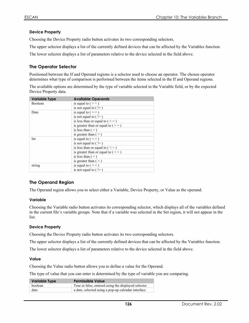
ESCAN Chapter 10: The Variables Branch
Device Property
Choosing the Device Property radio button activates its two corresponding selectors.
The upper selector displays a list of the currently defined devices that can be affected by the Variables function.
The lower selector displays a list of parameters relative to the device selected in the field above.
The Operator Selector Positioned between the If and Operand regions is a selector used to choose an operator. The chosen operator determines what type of comparison is performed between the items selected in the If and Operand regions.
The available options are determined by the type of variable selected in the Variable field, or by the expected Device Property data.
Variable Type Available Operands is equal to ( = = ) Boolean is not equal to ( != )
Date
is less than or equal to ( < = ) is greater than or equal to ( > = ) is less than ( < )
Int
is greater than ( > ) string is equal to ( = = ) is not equal to ( != )
is equal to ( = = ) is not equal to ( != ) is less than or equal to ( < = ) is greater than or equal to ( > = ) is less than ( < ) is greater than ( > ) is equal to ( = = ) is not equal to ( != )
The Operand Region The Operand region allows you to select either a Variable, Device Property, or Value as the operand.
Variable
Choosing the Variable radio button activates its corresponding selector, which displays all of the variables defined in the current file’s variable groups. Note that if a variable was selected in the Set region, it will not appear in the list.
Device Property
Choosing the Device Property radio button activates its two corresponding selectors.
The upper selector displays a list of the currently defined devices that can be affected by the Variables function.
The lower selector displays a list of parameters relative to the device selected in the field above.
Value
Choosing the Value radio button allows you to define a value for the Operand.
The type of value that you can enter is determined by the type of variable you are comparing.
Variable Type Permissible Value boolean True or false, entered using the displayed selector date a date, selected using a pop-up calendar interface
126 Document Rev. 2.02

ESCAN Chapter 10: The Variables Branch
Variable Type Permissible Value int an integer, entered by typing the value in the text
box. string A text string, entered by typing it in the text box
Note
The data entered in the Value field must be less that 1,000 characters in length.
The Device to Control Region
Device Selector
Use the Device selector to choose which function executes as a result of the if/then statement.
The options are listed below:
User-defined Devices
Select to create a cue that will control the attached device.
Scheduler
Device Control Button
Clicking the Device Control button produces an interface dependant on the selection made using the Device selector:
If a user-defined device appears in the Device selector, a dialog box with options specific to that piece of equipment will appear.
If Scheduler appears in the Device selector, the Edit Schedule dialog box will appear. This allows you to incorporate commands that control events internal to ESCAN, such as starting and stopping Sequences, disabling a device’s comms, etc. The Edit Schedule dialog box is explained in Chapter 7, The Sequences Branch, on page 73.
Select to create a cue that will control Sequence, Schedule, and Comms events internal to ESCAN.
The Device Control Button
Menu Selections
Variables | Add Variable Group Opens the Add New Variable Group dialog box, and creates a new variable group
Variables | Delete This Variable Group
Deletes the selected variable group
Note
The Variables menu is only visible when a Variables (variable group) window is active.
127 Document Rev. 2.02
ESCAN Chapter 10: The Variables Branch
This page intentionally left blank.
128 Document Rev. 2.02

ESCAN Chapter 11: VideoServer Control
Chapter 11: VideoServer Control
VideoServer Overview
A key element of ESCAN is its ability to control MediaSonic VideoServers. Using ESCAN, you can integrate VideoServer-resident MPEG2 files into your presentation by utilizing search, play, stop, loop, and other control commands.
This chapter will guide you through the ESCAN configuration and control of a VideoServer.
VideoServer Control — Tutorial
VideoServer Tutorial
Control of a VideoServer requires the following steps:
Defining a Comms port to control the server Creating a VideoServer device Creating one or more play lists Creating Sequences that control the VideoServer
This tutorial will walk you through these steps. While the tutorial in Chapter 4 was an exercise meant to familiarize you with ESCAN, this tutorial assumes you have a functioning VideoServer connected to a registered ESCAN PC, so you can actually control the device.
This chapter also assumes a level of familiarity with ESCAN, as described in Chapters 5 through 10.
Note
In order to perform the tutorial, you need to have the ESCAN PC and the VideoServer properly configured for communication. This is done by defining a Communication Method in the VideoServer that matches the Comms port definition in ESCAN. VideoServer Communication Methods are not discussed in this manual.
This tutorial makes reference to sample MPEG files installed on the Standard Definition VideoServer. If your server does not have these files installed, you will need to install your own files and substitute their paths and file names at the appropriate places in the tutorial.
Creating a New File. Create a new file by clicking on the New File button, or selecting File | New from the top line menu.
ESCAN’s New File Button
A new, empty file called “Untitled1.ess” (or similar name) will be created.
129 Document Rev. 2.02

ESCAN Chapter 11: VideoServer Control
Saving the File. Before getting started, you should save the file.
To save the file, click on ESCAN’s Save button, or select File | Save As… from the top line menu.
ESCAN’s Save Button
Windows’ Save As dialog box will appear. Assign the name “ServerTutorial” to the file, and click Save.
Setting the System’s Frame Rate. Set the system’s frame rate to the appropriate setting for your locale.
For more information on setting the system’s frame rate, refer to page 3 . 2
Configuring the VideoServer’s Comms Port.
Defining the Comms Port
1. Right-click on the Comms icon in the Workspace tree.
The Comms Icon
2. Click on Add Comm Port from the pop-up menu that appears.
Comms Pop-up Menu
The Communications Port Setting dialog box will appear.
3. Enter “VideoServer Control Port” in the Name field.
4. Select the TCP/IP option, and type in the IP address of the VideoServer (if the server’s IP address is static), or the computer name (if the server’s IP address is dynamic) in the IP Address field.
5. Set the value in the IP Port field to 2100. Make sure the VideoServer’s Communication Method is set for this Port Number as well.
130 Document Rev. 2.02

ESCAN Chapter 11: VideoServer Control
6. Make sure the dialog box looks like the following example, and then click the OK button (your IP address may differ from the one shown below).
Proper Settings for the VideoServer Port
Opening the Comms Port
You should be able to open the VideoServer’s Comms port. Right-click on the port definition, and select Open Port. The icon should turn green as shown below.
VideoServer Port Open
If the port does not open, verify the port settings, and make sure they coincide with the IP information and the Communication Method of the VideoServer.
VideoServer Port Unable to Open
Once you are able to open the Comms port, you can proceed to the next step, defining the VideoServer device.
Defining the VideoServer Device. 1. Right-click on the Devices icon in the Workspace tree.
The Devices Icon
2. Click on Add Device from the pop-up menu that appears.
Device Pop-Up Menu
The Add Device dialog box will appear
3. From the Device Type drop-down list, select “MS VideoServer.”
4. In the Device Name field, type “MS VideoServer.”
131 Document Rev. 2.02

ESCAN Chapter 11: VideoServer Control
5. Make sure the dialog box looks like the example shown below, and then click the OK button.
Proper Settings for the VideoServer Device
A Properties dialog box for the VideoServer will open.
6. From the Comms tab, you will choose the communication port you defined for the VideoServer earlier in the tutorial. Click on the drop-down list, and choose “VideoServer Control Port.”
7. Leave the Enable Receive box checked.
8. You will not make any changes to the Triggers tab. Make sure the dialog box looks like the example shown below, and then click the OK button.
MS VideoServer Properties
Connecting the VideoServer Device
Activating the Scheduler at this point should connect the VideoServer device. Press F9 to activate the Scheduler. The icon should turn green as shown below.
VideoServer Device Connected
If the device does not connect, verify the port settings, and make sure they coincide with the IP information and the Communication Method of the VideoServer.
VideoServer Device Unable to Connect
Once you are able to connect the VideoServer device, you can proceed to the next step, creating play lists.
132 Document Rev. 2.02

ESCAN Chapter 11: VideoServer Control
Creating Play Lists. Before you can control the VideoServer, you need to create play lists that contain the names and locations of the video files you wish to play. You can create as many play lists as you need to help you organize the video clips. In this tutorial, you will create two play lists — one for each of two VideoServer channels.
Creating the First Play List
The first play list will contain data for a one video file, played from channel 1 of the VideoServer.
1. Expand the Devices icon and the MS VideoServer icon in the Workspace tree.
Expanded Devices Icon and VideoServer Icons
2. Double-click on the Play Lists icon. An empty Play List window will appear.
The Play List Window
3. Click on the Play List Options button in the Play List window.
The Play List Options Button
4. Select New Playlist… from the pop-up menu that appears.
Play List Menu Options
The Create New Playlist dialog box will appear.
5. Type “Channel 1: Zoo” in the text field, and click OK.
Create New Play List Dialog Box
A new play list is created with the name you just assigned. It will appear at the top of the window, displayed in the play list selector.
133 Document Rev. 2.02

ESCAN Chapter 11: VideoServer Control
Blank Channel 1 : Zoo Play List
6. Right-click in the area below the ID/Play List heading, and select Add Clip from the pop-up menu that appears. A blank entry line will appear in the play list area.
Play List Clip Menu
7. Type D:\MPEG\Zoo Sequence.mpg in the entry field, and press Enter. This information corresponds to a sample file on the VideoServer, and will tell the VideoServer software where to find the clip. This will be the only entry in this play list.
Entering the Clip Data
The completed play list is shown below:
The Completed Zoo Play List
Creating the Second Play List
You will now create another play list. This second play list will contain data for two files, played from channel 2 of the VideoServer.
As you have already completed this process once, this time you will be given a little less instruction and fewer visuals.
1. Click on the Play List Options button in the Play List window, and select New Playlist… from the pop-up menu that appears
The Play List Options Button
134 Document Rev. 2.02
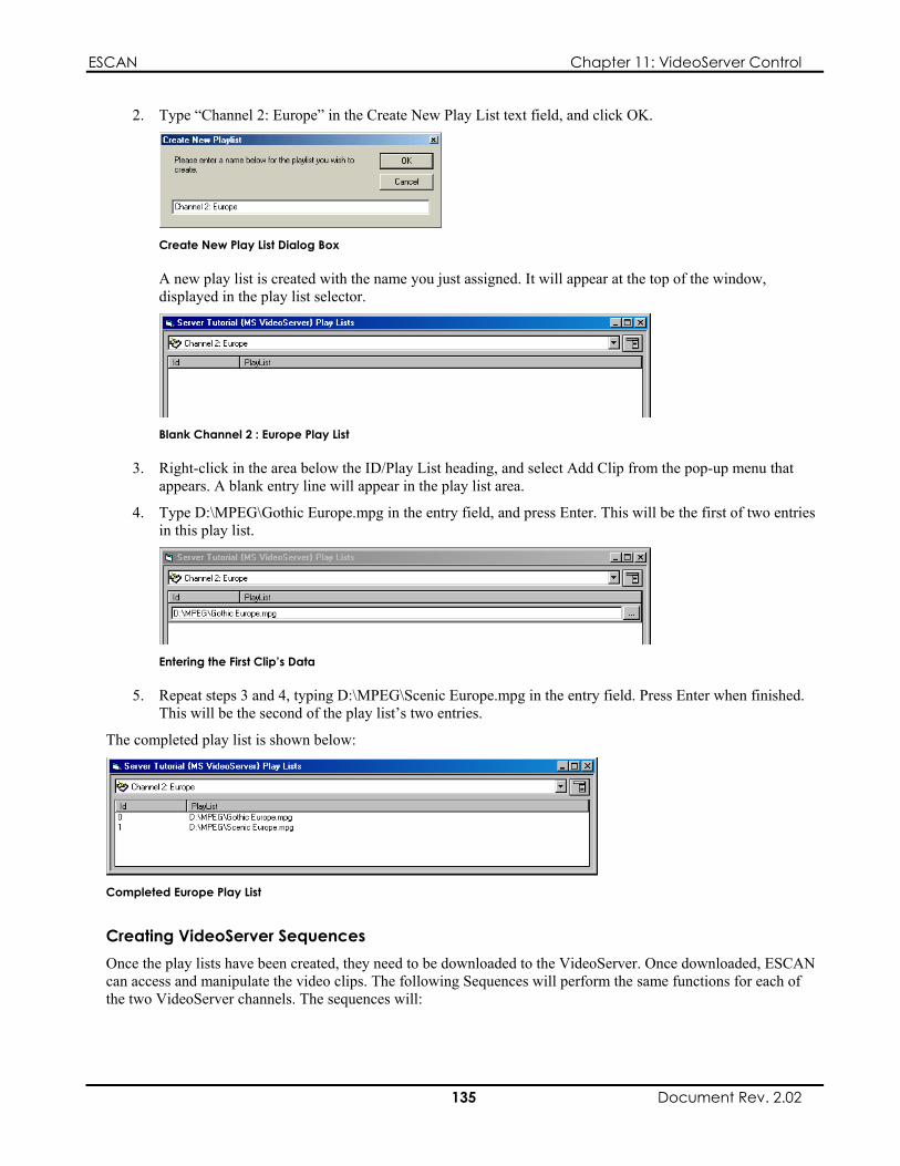
ESCAN Chapter 11: VideoServer Control
2. Type “Channel 2: Europe” in the Create New Play List text field, and click OK.
Create New Play List Dialog Box
A new play list is created with the name you just assigned. It will appear at the top of the window, displayed in the play list selector.
Blank Channel 2 : Europe Play List
3. Right-click in the area below the ID/Play List heading, and select Add Clip from the pop-up menu that appears. A blank entry line will appear in the play list area.
4. Type D:\MPEG\Gothic Europe.mpg in the entry field, and press Enter. This will be the first of two entries in this play list.
Entering the First Clip’s Data
5. Repeat steps 3 and 4, typing D:\MPEG\Scenic Europe.mpg in the entry field. Press Enter when finished. This will be the second of the play list’s two entries.
The completed play list is shown below:
Completed Europe Play List
Creating VideoServer Sequences Once the play lists have been created, they need to be downloaded to the VideoServer. Once downloaded, ESCAN can access and manipulate the video clips. The following Sequences will perform the same functions for each of the two VideoServer channels. The sequences will:
135 Document Rev. 2.02
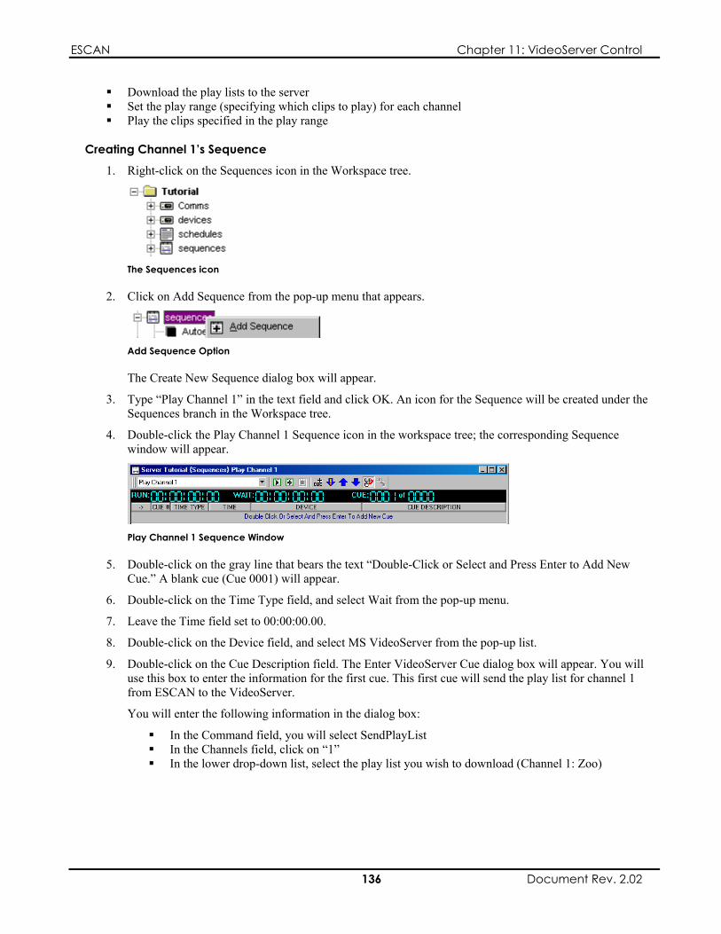
ESCAN Chapter 11: VideoServer Control
Download the play lists to the server Set the play range (specifying which clips to play) for each channel Play the clips specified in the play range
Creating Channel 1’s Sequence
1. Right-click on the Sequences icon in the Workspace tree.
The Sequences icon
2. Click on Add Sequence from the pop-up menu that appears.
Add Sequence Option
The Create New Sequence dialog box will appear.
3. Type “Play Channel 1” in the text field and click OK. An icon for the Sequence will be created under the Sequences branch in the Workspace tree.
4. Double-click the Play Channel 1 Sequence icon in the workspace tree; the corresponding Sequence window will appear.
Play Channel 1 Sequence Window
5. Double-click on the gray line that bears the text “Double-Click or Select and Press Enter to Add New Cue.” A blank cue (Cue 0001) will appear.
6. Double-click on the Time Type field, and select Wait from the pop-up menu.
7. Leave the Time field set to 00:00:00.00.
8. Double-click on the Device field, and select MS VideoServer from the pop-up list.
9. Double-click on the Cue Description field. The Enter VideoServer Cue dialog box will appear. You will use this box to enter the information for the first cue. This first cue will send the play list for channel 1 from ESCAN to the VideoServer.
You will enter the following information in the dialog box:
In the Command field, you will select SendPlayList In the Channels field, click on “1” In the lower drop-down list, select the play list you wish to download (Channel 1: Zoo)
136 Document Rev. 2.02
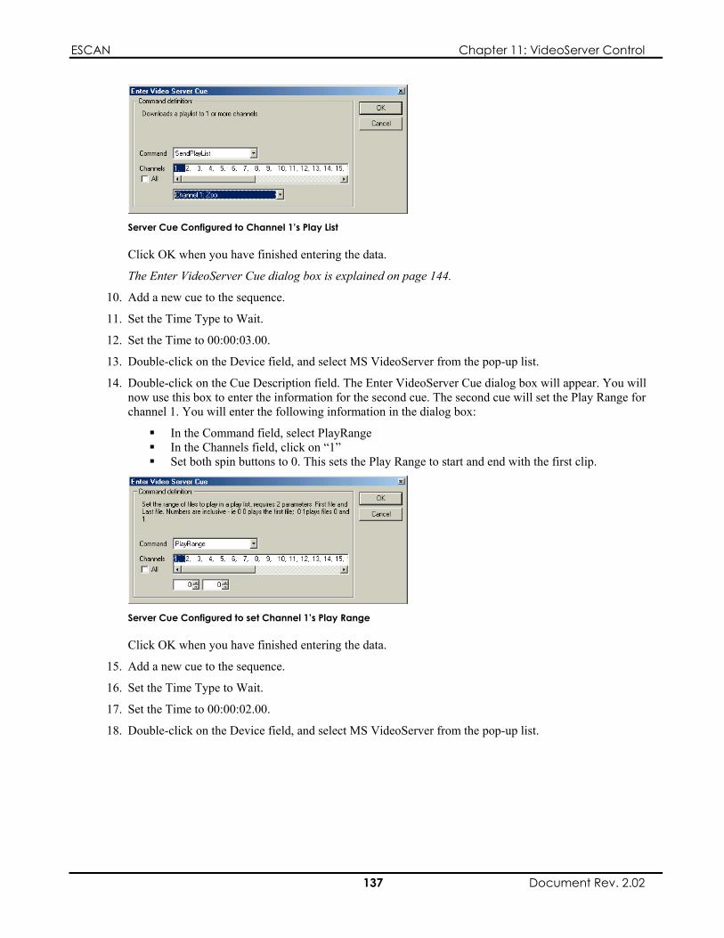
ESCAN Chapter 11: VideoServer Control
Server Cue Configured to Channel 1’s Play List
Click OK when you have finished entering the data.
The Enter VideoServer Cue dialog box is explained on page 1 . 44
10. Add a new cue to the sequence.
11. Set the Time Type to Wait.
12. Set the Time to 00:00:03.00.
13. Double-click on the Device field, and select MS VideoServer from the pop-up list.
14. Double-click on the Cue Description field. The Enter VideoServer Cue dialog box will appear. You will now use this box to enter the information for the second cue. The second cue will set the Play Range for channel 1. You will enter the following information in the dialog box:
In the Command field, select PlayRange In the Channels field, click on “1” Set both spin buttons to 0. This sets the Play Range to start and end with the first clip.
Server Cue Configured to set Channel 1’s Play Range
Click OK when you have finished entering the data.
15. Add a new cue to the sequence.
16. Set the Time Type to Wait.
17. Set the Time to 00:00:02.00.
18. Double-click on the Device field, and select MS VideoServer from the pop-up list.
137 Document Rev. 2.02
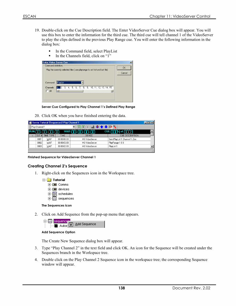
ESCAN Chapter 11: VideoServer Control
19. Double-click on the Cue Description field. The Enter VideoServer Cue dialog box will appear. You will use this box to enter the information for the third cue. The third cue will tell channel 1 of the VideoServer to play the clips defined in the previous Play Range cue. You will enter the following information in the dialog box:
In the Command field, select PlayList In the Channels field, click on “1”
Server Cue Configured to Play Channel 1’s Defined Play Range
20. Click OK when you have finished entering the data.
Finished Sequence for VideoServer Channel 1
Creating Channel 2’s Sequence
1. Right-click on the Sequences icon in the Workspace tree.
The Sequences icon
2. Click on Add Sequence from the pop-up menu that appears.
Add Sequence Option
The Create New Sequence dialog box will appear.
3. Type “Play Channel 2” in the text field and click OK. An icon for the Sequence will be created under the Sequences branch in the Workspace tree.
4. Double click on the Play Channel 2 Sequence icon in the workspace tree; the corresponding Sequence window will appear.
138 Document Rev. 2.02

ESCAN Chapter 11: VideoServer Control
5. Double-click on the gray line that bears the text “Double-Click or Select and Press Enter to Add New Cue.” A blank cue (Cue 0001) will appear.
6. Double-click on the Time Type field, and select Wait from the pop-up menu.
7. Leave the Time field set to 00:00:00.00.
8. Double-click on the Device field, and select MS VideoServer from the pop-up list.
9. Double-click on the Cue Description field. The Enter VideoServer Cue dialog box will appear. You will use this box to enter the information for the first cue. This first cue will send the playlist for channel 2 from ESCAN to the VideoServer. You will enter the following information in the dialog box:
In the Command field, you will select SendPlayList In the Channels field, click on “2” In the lower drop-down list, select the play list you wish to download (Channel 2: Europe)
Server Cue Configured to Channel 2’s Playlist
Click OK when you have finished entering the data.
The Enter VideoServer Cue dialog box is explained on page 1 . 44
10. Add a new cue to the sequence.
11. Set the Time Type to Wait.
12. Set the Time to 00:00:03.00.
13. Double-click on the Device field, and select MS VideoServer from the pop-up list.
14. Double-click on the Cue Description field. The Enter VideoServer Cue dialog box will appear. You will now use this box to enter the information for the second cue. The second cue will set the play range for channel 2. You will enter the following information in the dialog box:
In the Command field, select PlayRange In the Channels field, click on “2” Set the left spin button to 0, and the right spin button to 1. This sets the Play Range to start with
the first clip and end with the second clip.
Server Cue Configured to set Channel 2’s Play Range
139 Document Rev. 2.02
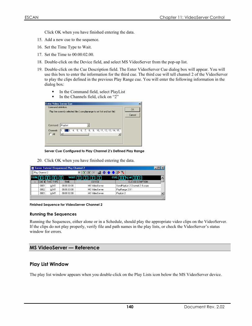
ESCAN Chapter 11: VideoServer Control
Click OK when you have finished entering the data.
15. Add a new cue to the sequence.
16. Set the Time Type to Wait.
17. Set the Time to 00:00:02.00.
18. Double-click on the Device field, and select MS VideoServer from the pop-up list.
19. Double-click on the Cue Description field. The Enter VideoServer Cue dialog box will appear. You will use this box to enter the information for the third cue. The third cue will tell channel 2 of the VideoServer to play the clips defined in the previous Play Range cue. You will enter the following information in the dialog box:
In the Command field, select PlayList In the Channels field, click on “2”
Server Cue Configured to Play Channel 2’s Defined Play Range
20. Click OK when you have finished entering the data.
Finished Sequence for VideoServer Channel 2
Running the Sequences
Running the Sequences, either alone or in a Schedule, should play the appropriate video clips on the VideoServer. If the clips do not play properly, verify file and path names in the play lists, or check the VideoServer’s status window for errors.
MS VideoServer — Reference
Play List Window
The play list window appears when you double-click on the Play Lists icon below the MS VideoServer device.
140 Document Rev. 2.02

ESCAN Chapter 11: VideoServer Control
The Play Lists Icon
The Play Lists window allows you to create new play lists, and define the clips contained within.
The window is comprised of three areas:
The Play List selector The Play List Options button The Play List area
Play List Options Button
Play List Selector
Play List Area
Play List Window
Play List Selector
Clicking on this field shows the currently defined play lists. Selecting one of the play lists will show its clip listing in the Play List area.
Play List Options Button
Clicking on the Play List Options button produces a pop-up menu with options that let you create and modify the VideoServer play lists.
The details of the pop-up menu are explained in the next section, titled “Play List Options Menu.”
The Play List Options Button
Play List Area
The Play List area shows the clips that are included in the currently selected play list.
Right-clicking in this area produces a pop-up menu that allows you to create and edit the clip listing. The details of the pop-up menu are explained on page 1 . 43
Play List Options Menu
Clicking on the Play List Options button produces a pop-up menu with the following options:
New Playlist Copy Playlist
141 Document Rev. 2.02

ESCAN Chapter 11: VideoServer Control
Delete Playlist Delete All Import Playlist Export Playlist
These options, explained below, let you create and modify the VideoServer play lists.
Play List Options Menu
New Playlist
Selecting New Playlist will open the Create New Play List window, which allows you to create and name a new play list.
Create New Playlist Window
Copy Playlist
Selecting Copy Playlist will open the Copy Play List window. Typing a name in the text field and clicking OK will copy the contents of the currently displayed play list to a new play list bearing the name you just entered.
Copy Playlist Window
Delete Playlist
Selecting Delete Playlist will delete the currently displayed play list. You will be prompted to confirm the action before the play list is deleted.
Delete All
Selecting Delete All will delete all of the play lists in the current file. You will be prompted to confirm the action before the play lists are deleted.
142 Document Rev. 2.02

ESCAN Chapter 11: VideoServer Control
Import Playlist
Selecting Import Playlist will open the Import Play List dialog box. This feature allows you to enter a name for a new play list, and then browse to an existing .lst (play list) file to import under the new name.
The new play list will then appear in the play list selector.
Import Play List Dialog Box
Export Playlist
Selecting Export Playlist will open Windows’ Save As dialog box. Choosing a file name and destination directory will export the currently displayed play list to the specified location.
Play List Area Menu
Right-clicking in the Play Lists window’s Play List area produces a pop-up menu with the following options:
Add Clip Insert Clip Edit Clip Delete Clip Delete All Clips
These options, explained below, let you create and modify entries in the current play list.
Play List Area Pop-up Menu
Add Clip
Selecting Add Clip will open an entry line in the Play List area. Typing the path and file name of a clip and pressing Enter will append the clip name and path to the end of the play list.
Entering Clip Data
Insert Clip
Selecting Insert Clip will open an entry line in the Play List area. Typing the path and file name of a clip and pressing Enter will insert the information prior to the entry you clicked on.
143 Document Rev. 2.02

ESCAN Chapter 11: VideoServer Control
Edit Clip
Selecting Edit Clip will open an entry line showing the data for the line you clicked on. The information can then be modified.
Delete Clip
Right-clicking on an entry and selecting Delete Clip will delete the selected entry.
Delete All Clips
Right-clicking in the Play List area and selecting Delete All Clips will delete all the entries in the play list.
Enter VideoServer Cue Dialog Box
The Enter VideoServer Cue dialog box appears when creating a VideoServer cue in a Sequence or Schedule.
The dialog box is comprised of four fields:
The Command Selector The Channel List The Parameter Field The Select All Channels Option
Command Selector Channel List
Parameter Field
Select All Channels Option
The Enter VideoServer Cue Dialog Box
The Command Selector
The Command selector displays a list of available commands for MS VideoServer control. After selecting a command, the Parameter field will change appearance or disappear entirely, based on the Command selected. The Channel field may also disappear if the command selected does not apply to individual channels.
The list of available commands is shown below, along with an explanation their function and parameters.
Command Function Send PlayList Downloads a play list to the selected channels List of defined playlists PlayList Plays the clips in the play list files as defined by
the PlayRange command None
PlayRange Sets the range of the files to play in the play list First and last file for the play range
Parameters
144 Document Rev. 2.02

ESCAN Chapter 11: VideoServer Control
Command Function Parameters Play Starts the selected channel(s) playing None Stop Stops the selected channel(s) None Seek Seeks the currently selected file to the specified
frame Desired frame number
Search Seeks the currently selected file to the specified frame
Desired frame number
Clear Clear the play list for the selected channel(s) None Add Adds a file to the play list for the selected
channel(s) Path and file name of clip to be added
Syncgroup Defines the sync group for the selected channels; this is useful when playing channels in a synchronized manner
Name for the sync group
Syncplay Plays the specified sync group Name of the sync group to play, as defined in the Syncgroup command
Syncstop Stops the specified sync group from playing Name of the sync group to stop, as defined in the Syncgroup command
Syncbreak Breaks the sync group association for the specified Sync group
Name of the sync group to break
LoopOn Loops the specified channel(s) None LoopOff Stops the specified channel(s) from looping None AudioOn Turns the audio on for the specified channel(s) None AudioOff Turns the audio off for the specified channel(s) None VideoOn Turns the video on for the specified channel(s) None VideoOff Turns the video off for the specified channel(s) None ShutDown Shuts down the VideoServer None Reboot Shuts down and reboots the VideoServer None Exit Exits the VideoServer application None ioctl Advanced users only Advanced users only ChangeStartChapter Changes the start chapter without loading the
file; generally used only with LoopOn The desired chapter number
PlayRangeImmediate Plays the specified range of chapters without the need for a Play command
First and last file for the PlayRange
Switch Switch to a different named Play List List of defined playlists
The Channel List
If the selected command can be applied to individual VideoServer channels, the Channel list will appear. Select the channel(s) you wish the command to affect by clicking on the channel number.
The Select All Channels Option
If you wish the selected command to apply to all VideoServer channels, you can save time by checking the Select All Channels tick-box instead of manually clicking on each channel number.
The Parameter Field
If the selected command requires additional information to execute, the Parameter field will switch to a text box, drop-down list, or other appropriate interface to enter the required data.
The command list above shows the required data for each parameter.
145 Document Rev. 2.02

ESCAN Chapter 11: VideoServer Control
This page intentionally left blank.
146 Document Rev. 2.02

ESCAN Appendix A: TCP/IP Communication
Appendix A: TCP/IP Communication
An Introductory Note
A full explanation of Ethernet communication is beyond the scope of this user’s guide. However, the following details will provide you with enough information to understand the basic concepts of TCP/IP communication.
Ethernet Communication
Designed to connect many devices (called a “network”) on a single port
Maximum speeds beyond 100 Mbps
TCP/IP Addressing
Dynamic assignment
ESCAN allows you to communicate with peripheral devices via RS-232 and Ethernet connections. Most people with a technical background are familiar with RS-232 communication. Ethernet communication, while not a new development, is still a mystery to many.
Let’s compare the differences between RS-232 and Ethernet data:
RS-232
Designed for one port to connect to one device Messages transmitted as a whole No way to guarantee data does not get sent to the wrong device Maximum speeds of around 115 Kbps
Ethernet
Messages transmitted in “packets”, as network traffic allows Each device in the network has a unique address, ensuring that a data message goes only to the specified
device
Several types of Ethernet communications exist. The protocol, or language, that ESCAN uses for its Ethernet communication is called TCP/IP (Transmission Control Protocol and Internet Protocol).
Each device on a network needs a unique address so data is sent only to the device it is intended to reach. Two methods exist for assigning an Ethernet addresses in a TCP/IP network:
Static assignment
Static Assignment
Static assignment allows the user to assign an IP address to a device. Once assigned, it will always retain the assigned address.
147 Document Rev. 2.02

ESCAN Appendix A: TCP/IP Communication
Dynamic Assignment
The IP Address
An IP address is divided into two parts:
On a given network, each address must have the same network identifier value but have a unique host identifier.
The above examples are representative of a “Class C” network. Classes are explained in the next section.
There are different “classes” of IP addresses that define:
The most common IP address classes are:
Dynamic address assignment requires the use of a DHCP (Dynamic Host Configuration Protocol) server that automatically assigns an address to a network device each time it connects. When the device connects, it may be assigned an address that differs from the address it was last assigned.
The following sections discuss the structure of IP addresses, and how to assign a static and dynamic address to a device.
An IP address is a 32-bit binary number that is used to identify each device on an Ethernet network. This number is usually represented by four decimal numbers (each in the range 0 to 255), separated by dots (e.g., 198.123.34.240). This is called “dotted decimal notation.”
Network and Host Identifiers
The network identifier The host identifier
For example, the following two IP addresses could exist on the same network:
208.132.180.40 208.132.180.55
This assumes that 208.132.180 is the network identifier, and 40 and 55 are the host identifiers.
Class Names
There are rules governing the valid numbers that can be assigned as network identifiers and host identifiers. The valid numbers are assigned “classes.”
The range of valid addresses Which parts of the address are used for the network and host identifiers
Class Name Valid Address Class A 0.0.0.1 to 127.255.255.254 NNN.HHH.HHH.HHH Class B 128.0.0.1 to 191.255.255.254 NNN.NNN.HHH.HHH
192.0.0.1 to 223.255.255.254 NNN.NNN.NNN.HHH
Range Identifier Arrangement
Class C
Where:
NNN = Network identifier HHH = Host identifier
Choosing IP Addresses
Two scenarios exist that will dictate the IP address assigned to your devices: whether you are connecting to an existing network or establishing an independent network.
148 Document Rev. 2.02

ESCAN Appendix A: TCP/IP Communication
Connecting to an Existing Network
If your ESCAN computer and attached devices are connected via their own independent network, you can assign an IP address of your choice to each device. Follow the guidelines below for choosing your IP address(es).
The network identifier must be the same for each address
Class C
If your ESCAN computer and attached devices are connecting to an existing network, you will need to check with the network administrator to determine if the devices require a static IP address, or if they should be configured for dynamic IP address assignment. If the devices require static IP addresses, ask the administrator to allocate suitable addresses to you.
Establishing an Independent Network
On an independent network you can (in theory) use just about any addresses you wish. However, it is generally recommended that you use the Class C format (i.e., from 192.0.0.1 up to 223.255.255.253).
Remember that there are two rules for choosing IP addresses:
The host identifier must be unique for each address
Applying these rules to Class C addresses, it can be seen that the first three decimal values of your IP addresses must all be the same, while the last value is used to uniquely identify each device.
The following is an example of a valid Class C addressing scheme:
Device IP Address
ESCAN PC 208.132.180.41 Ethernet Device 1 208.132.180.42 Ethernet Device 2 208.132.180.43
The following is an example of an invalid Class C addressing scheme:
Device IP Address
ESCAN PC 208.132.180.41 Ethernet Device 1 192.157.180.42 Ethernet Device 2 209.100.123.43
Note
These are invalid because the network identifier for each address is not the same, even though each IP address is unique.
One more concept must be discussed in order to properly assign an IP address; that of the Subnet Mask.
The Subnet Mask
The Subnet Mask is another 32-bit binary number that is used to “mask” certain bits of the IP address. This provides a method of extending the number of network options for a given IP address. It works by allowing part of the host identifier to be used as a “subnet identifier”.
It is important that you set the correct value for the Subnet Mask. The basic values depend on the class of IP address being used:
Class Name Subnet Mask
Class A 255.0.0.0 Class B 255.255.0.0
255.255.255.0
149 Document Rev. 2.02

ESCAN Appendix A: TCP/IP Communication
Accessing the PC’s Subnet Mask and IP Address: Win 98 & NT
Opening the Network Dialog Box: Windows 98, and NT
After performing either of the previous steps, the Network dialog box will appear.
The PC’s IP address is located in the Network dialog box, which can be accessed in the following manner:
By right-clicking on the Network Neighborhood desktop shortcut, and then clicking left on Properties. Alternatively, the Network dialog box can be opened by clicking on Windows’ Start button, selecting
Settings, selecting Control Panel, and then double-clicking on the Network icon.
The Network Dialog Box: Windows 98 The Network Dialog Box: Windows NT
Accessing the IP Address and Subnet Mask: Windows 98
To access the PC’s IP address from the Network dialog box, perform the following procedure:
1. Scroll down the list of installed network components, and click on the one labeled “TCP/IP.”
Note
Multiple TCP/IP listings may appear in the list. If this is the case, select the TCP/IP component that is followed by the name of the network card connected to the ESCAN Device you wish to control.
If TCP/IP does not appear in the list, it will need to be installed.
2. After selecting the correct TCP/IP component, click the Properties button. The TCP/IP Properties dialog box will appear, showing the TCP/IP address and the Subnet Mask.
150 Document Rev. 2.02
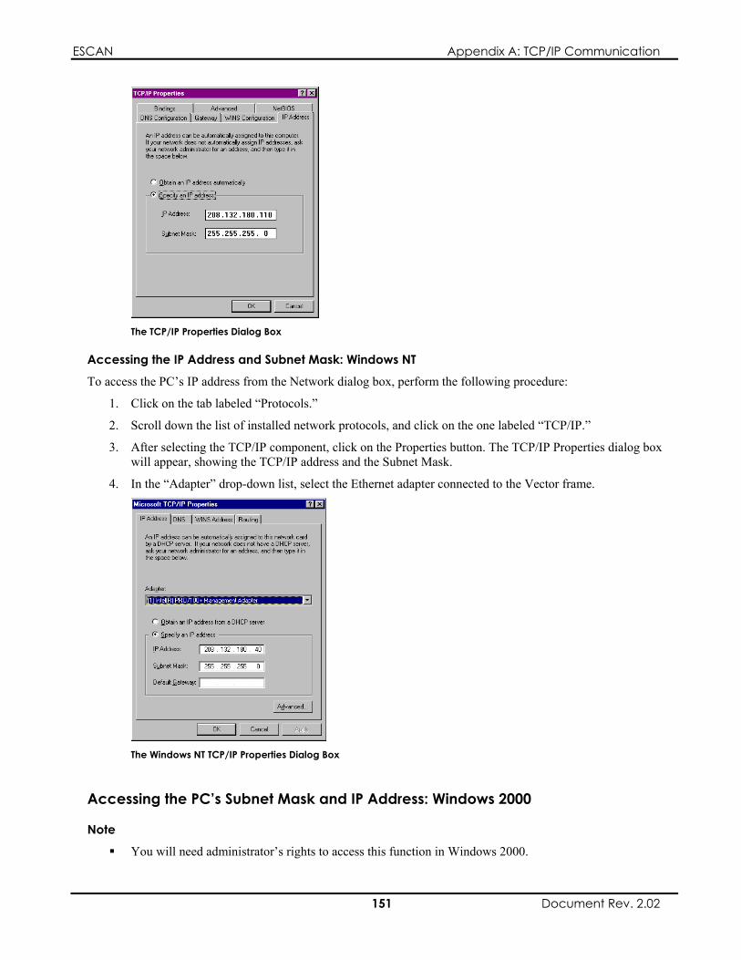
ESCAN Appendix A: TCP/IP Communication
The TCP/IP Properties Dialog Box
Accessing the IP Address and Subnet Mask: Windows NT
To access the PC’s IP address from the Network dialog box, perform the following procedure:
1. Click on the tab labeled “Protocols.”
2. Scroll down the list of installed network protocols, and click on the one labeled “TCP/IP.”
3. After selecting the TCP/IP component, click on the Properties button. The TCP/IP Properties dialog box will appear, showing the TCP/IP address and the Subnet Mask.
4. In the “Adapter” drop-down list, select the Ethernet adapter connected to the Vector frame.
The Windows NT TCP/IP Properties Dialog Box
Accessing the PC’s Subnet Mask and IP Address: Windows 2000
Note
You will need administrator’s rights to access this function in Windows 2000.
151 Document Rev. 2.02
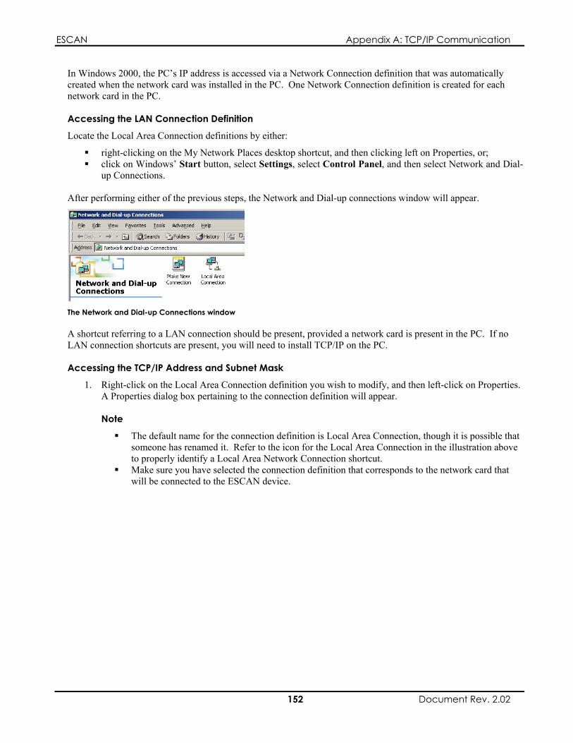
ESCAN Appendix A: TCP/IP Communication
In Windows 2000, the PC’s IP address is accessed via a Network Connection definition that was automatically created when the network card was installed in the PC. One Network Connection definition is created for each network card in the PC.
Accessing the LAN Connection Definition
Locate the Local Area Connection definitions by either:
right-clicking on the My Network Places desktop shortcut, and then clicking left on Properties, or; click on Windows’ Start button, select Settings, select Control Panel, and then select Network and Dial-
up Connections. After performing either of the previous steps, the Network and Dial-up connections window will appear.
The Network and Dial-up Connections window
A shortcut referring to a LAN connection should be present, provided a network card is present in the PC. If no LAN connection shortcuts are present, you will need to install TCP/IP on the PC.
Accessing the TCP/IP Address and Subnet Mask
1. Right-click on the Local Area Connection definition you wish to modify, and then left-click on Properties. A Properties dialog box pertaining to the connection definition will appear.
Note
The default name for the connection definition is Local Area Connection, though it is possible that someone has renamed it. Refer to the icon for the Local Area Connection in the illustration above to properly identify a Local Area Network Connection shortcut.
Make sure you have selected the connection definition that corresponds to the network card that will be connected to the ESCAN device.
152 Document Rev. 2.02

ESCAN Appendix A: TCP/IP Communication
The Network Connection Properties Dialog Box
2. Select Internet Protocol (TCP/IP).
Note
If “Internet Protocol (TCP/IP)” is not listed, refer to the document titled “Installing TCP/IP” for more information.
3. Click on the Properties button. The TCP/IP Properties dialog box will appear.
The TCP/IP Properties Dialog Box
153 Document Rev. 2.02
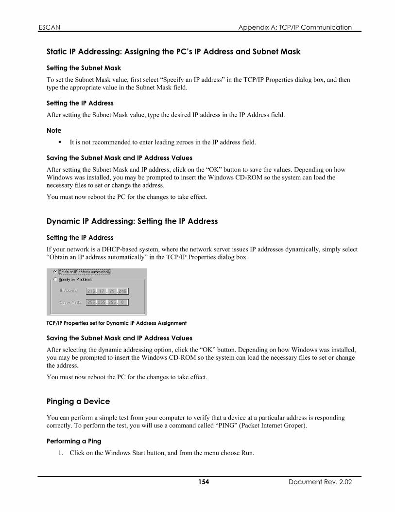
ESCAN Appendix A: TCP/IP Communication
Static IP Addressing: Assigning the PC’s IP Address and Subnet Mask
Setting the Subnet Mask
To set the Subnet Mask value, first select “Specify an IP address” in the TCP/IP Properties dialog box, and then type the appropriate value in the Subnet Mask field.
Setting the IP Address
After setting the Subnet Mask value, type the desired IP address in the IP Address field.
Note
It is not recommended to enter leading zeroes in the IP address field.
Saving the Subnet Mask and IP Address Values
After setting the Subnet Mask and IP address, click on the “OK” button to save the values. Depending on how Windows was installed, you may be prompted to insert the Windows CD-ROM so the system can load the necessary files to set or change the address.
You must now reboot the PC for the changes to take effect.
Dynamic IP Addressing: Setting the IP Address
Setting the IP Address
If your network is a DHCP-based system, where the network server issues IP addresses dynamically, simply select “Obtain an IP address automatically” in the TCP/IP Properties dialog box.
TCP/IP Properties set for Dynamic IP Address Assignment
Saving the Subnet Mask and IP Address Values
After selecting the dynamic addressing option, click the “OK” button. Depending on how Windows was installed, you may be prompted to insert the Windows CD-ROM so the system can load the necessary files to set or change the address.
You must now reboot the PC for the changes to take effect.
Pinging a Device
You can perform a simple test from your computer to verify that a device at a particular address is responding correctly. To perform the test, you will use a command called “PING” (Packet Internet Groper).
Performing a Ping
1. Click on the Windows Start button, and from the menu choose Run.
154 Document Rev. 2.02

ESCAN Appendix A: TCP/IP Communication
2. In the Run dialog box, type in the following:
ping xxx.xxx.xxx.xxx -t
Where “xxx.xxx.xxx.xxx” is the IP address that you want to test.
3. A DOS window will then open and show a series of responses as in the examples below.
4. To stop the ping command, press Ctrl + C on the keyboard.
Example 1: A successful Ping
If you have successfully “pinged” the address 208.132.180.39, you will get the following response:
Example 2: Unsuccessful Pings
Request timed out
indicates that there has been no response from the specified address. Either the device is not receiving data from the computer or the device is not sending data. Check the data cabling, power, and setup of the affected device.
Reply from 208.132.180.39: bytes=32 time=2ms TTL=32
This response indicates that the device at the specified address is communicating correctly. Note that the response time value may vary according to network traffic.
If you are not successful pinging the address, you will get one of two messages. The message returned will indicate the type of problem.
A message of:
A message of:
Reply from 208.132.180.48: Destination host unreachable
indicates that you are trying to ping an address with a different network identifier than your computer. Check the value of the PC’s IP address and compare it to that of the device — the network identifiers (the first three sets of numbers in the IP addresses) are mismatched.
155 Document Rev. 2.02

ESCAN Appendix A: TCP/IP Communication
This page intentionally left blank.
156 Document Rev. 2.02

ESCAN Appendix B: Time Code Support
Appendix B: Time Code Support
ESCAN and Time Code
Part of ESCAN’s power lies within its ability to generate and receive time code. This allows for the precise synchronization of your scheduled events with the other elements in your system.
Note
The information in this chapter is only applicable to versions of ESCAN running on Windows NT.
The PC2005 Card
In order for the ESCAN PC to receive and transmit time code, it must first be equipped with an Electrosonic time code card and cable.
Product Part Number Time Code Card ES2005 Time Code Cable ES4148
The ES2005 Time Code Card
The ES2005 is a full-length ISA card that occupies IRQ 3 (Com 2) of the control PC.
Note
The ES2005 card will only work when running ESCAN under Windows NT. The ES2005 is not a Plug-and-Play device, and will not show up in Windows’ Control Panel | System
tree view. Since the PC2005 card occupies IRQ 3, Com 2 and any other devices that occupy IRQ 3 must be disabled,
both in Windows and the PC’s BIOS.
The ES4148 Time Code Cable
The ES4148 time code cable connects to the time code card via a 37-pin D connector. The time code cable has a number of short female RCA leads that serve as connection points for the incoming or outgoing time code. A few different models of the cable exist, but all models contain at least one black RCA connection, and one red RCA connection. The black RCA connection is for incoming time code, and the red RCA connection is for outgoing time code.
Configuring the Frame Rate
ESCAN can receive or transmit time code at three different frame rates:
24 frames (Film) 25 frames (EBU) 30 frames (SMPTE)
The frame rate is determined by the selection in the Frame Rate tab of the ESCAN Configuration dialog box.
Refer to page 2 for more details. 2
157 Document Rev. 2.02
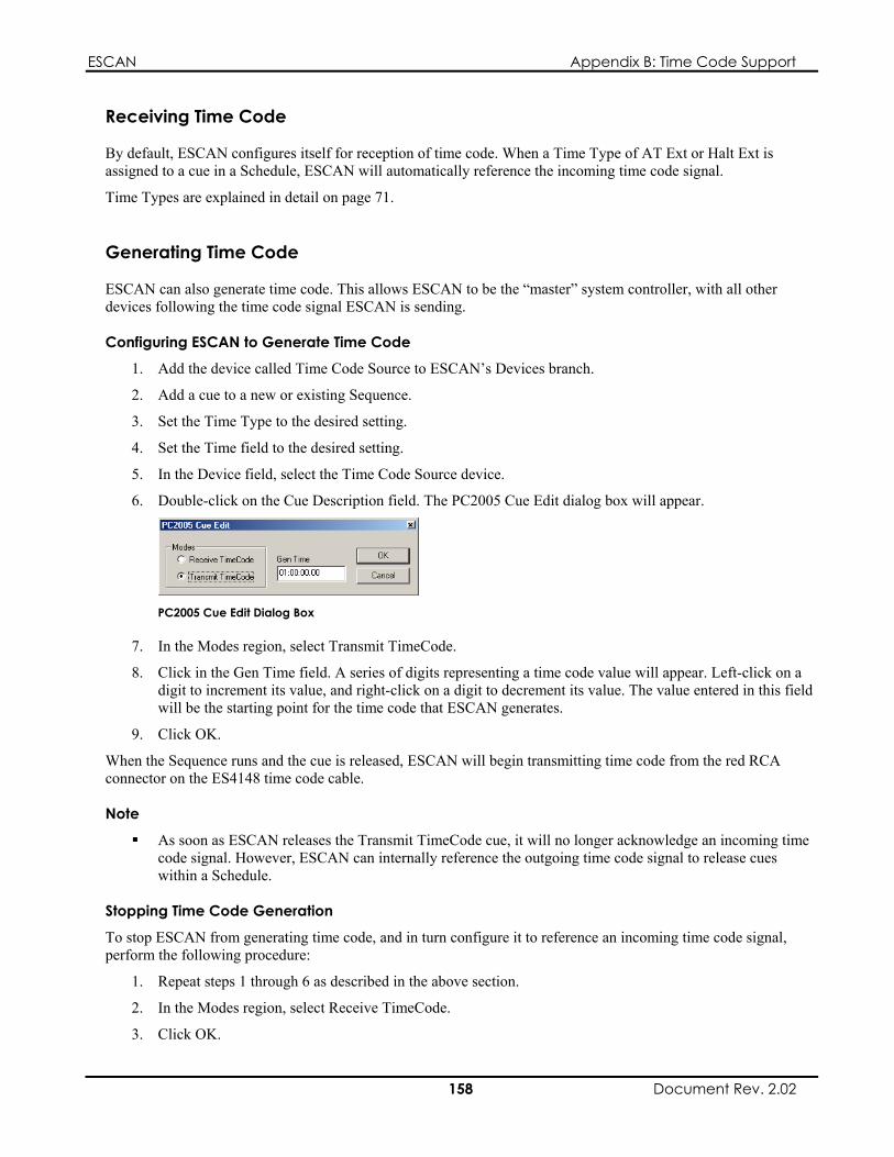
ESCAN Appendix B: Time Code Support
Receiving Time Code
By default, ESCAN configures itself for reception of time code. When a Time Type of AT Ext or Halt Ext is assigned to a cue in a Schedule, ESCAN will automatically reference the incoming time code signal.
Time Types are explained in detail on page 71.
1. Add the device called Time Code Source to ESCAN’s Devices branch.
5. In the Device field, select the Time Code Source device.
Generating Time Code
ESCAN can also generate time code. This allows ESCAN to be the “master” system controller, with all other devices following the time code signal ESCAN is sending.
Configuring ESCAN to Generate Time Code
2. Add a cue to a new or existing Sequence.
3. Set the Time Type to the desired setting.
4. Set the Time field to the desired setting.
6. Double-click on the Cue Description field. The PC2005 Cue Edit dialog box will appear.
PC2005 Cue Edit Dialog Box
7. In the Modes region, select Transmit TimeCode.
Note
1. Repeat steps 1 through 6 as described in the above section.
8. Click in the Gen Time field. A series of digits representing a time code value will appear. Left-click on a digit to increment its value, and right-click on a digit to decrement its value. The value entered in this field will be the starting point for the time code that ESCAN generates.
9. Click OK.
When the Sequence runs and the cue is released, ESCAN will begin transmitting time code from the red RCA connector on the ES4148 time code cable.
As soon as ESCAN releases the Transmit TimeCode cue, it will no longer acknowledge an incoming time code signal. However, ESCAN can internally reference the outgoing time code signal to release cues within a Schedule.
Stopping Time Code Generation
To stop ESCAN from generating time code, and in turn configure it to reference an incoming time code signal, perform the following procedure:
2. In the Modes region, select Receive TimeCode.
3. Click OK.
158 Document Rev. 2.02

ESCAN Appendix B: Time Code Support
When the Sequence runs and the cue is released, ESCAN will stop transmitting time code, and resume referencing an incoming time code signal.
159 Document Rev. 2.02

ESCAN Appendix B: Time Code Support
This page intentionally left blank.
160 Document Rev. 2.02
ESCAN Appendix C: XML Device Creation
Appendix C: ESCAN XML Device Creation
ESCAN Device Driver Overview
As described in previous chapters, ESCAN allows you to control, among other things, peripheral devices such as DVD players, VCRs, and switchers. To control these devices, ESCAN comes with a standard set of device drivers capable of controlling many popular audio-visual components.
Sometime, however, you may wish to control a device that is not supported by ESCAN’s standard set of device drivers. In such a circumstance, it is possible to create your own device drivers for integration into ESCAN.
using the ESCAN DDK (device developer kit), and;
Using XML
ESCAN DDK Device Drivers
A device driver created using ESCAN’s DDK will have a file extension of “esd”, and must reside in the ESCAN application’s devices folder as shown in the path below:
Multiple DDK device drivers can be placed in the devices folder.
ESCAN XML Device Drivers
Device drivers created using XML need to have a file extension of “esx”, and must also reside in ESCAN’s devices folder, as shown in the path below:
C:\Program Files\MediaSonic\ESCAN\devices\MyDevices.esx
Multiple XML device drivers can be placed in the devices folder, and DDK and XML device drivers can simultaneously be present in the folder as well.
Creating Device Drivers
A user can create a device driver in one of two ways:
using XML (extensible markup language) code.
Using the ESCAN DDK
ESCAN’s device developer kit allows you to create complex device drivers that support device control, monitoring, event triggering, complex cue editors, and status windows. However, using the DDK requires a high level of programming skill in Microsoft Visual C++. This will put DDK usage out of reach for a large number of ESCAN users.
Fortunately, it is still possible for those without computer-programming skills to create ESCAN device drivers. Using only a text editor and simple XML code, nearly anyone can create a device driver capable of sending commands to peripheral equipment. While advanced device driver features such as monitoring and triggering will be inaccessible using this method, you will still be able to send simple control commands to most devices.
File extensions and Locations
C:\Program Files\MediaSonic\ESCAN\devices\EslinxDevices.esd
161 Document Rev. 2.02
ESCAN Appendix C: XML Device Creation
Additional Information
A comprehensive discussion of the ESCAN DDK is beyond the scope of this manual. If you would like further information about developing device drivers with the DDK, please contact MediaSonic at:
The remainder of this chapter details the authoring of device drivers using XML code.
Internet Explorer 6.0
All tag n
Internet Explorer version 6.0 must be installed on the ESCAN computer in order for ESCAN to properly parse XML device drivers. If Internet Explorer 6.0 is not installed and ESCAN attempts to open an XML driver, a warning will appear indicating that an update to Internet Explorer is required.
XML Driver Creation
File Authoring
Any text editor (such as Microsoft’s Notepad) can be used to create XML device drivers. Since an XML file is nothing more than a text document, it is the responsibility of ESCAN’s XML parser to sort through the document and extract the appropriate information that makes up the driver. For example, the device driver needs to contain information such as the name of the device, the commands used to control the device, and the code that comprises each command. To help the parser know how to recognize these pieces of information, it is organized with the use of “open tags” and “close tags”, in the same manner as an HTML document.
An open tag indicates the start of a command or section. It is comprised of the characters “<” and “>”, and contains the command or section name.
<HDServer>
Example Open Tag
A close tag indicates the end of a command or section. It is identical to an open tag, but includes a forward slash before the command/section name.
</HDServer>
Example Close Tag
The tags must be used in sets (one open and one close) for proper parsing of the data.
Driver Structure
Eight tags are used to create ESCAN drivers. These tags are first shown in the sample driver file below, and then each one is explained in the following paragraphs. Note that some of the tags are used only once in the file, while some are used multiple times.
Note
The indentation shown in the example below is not necessary, but can be done for clarity ames are case sensitive
162 Document Rev. 2.02
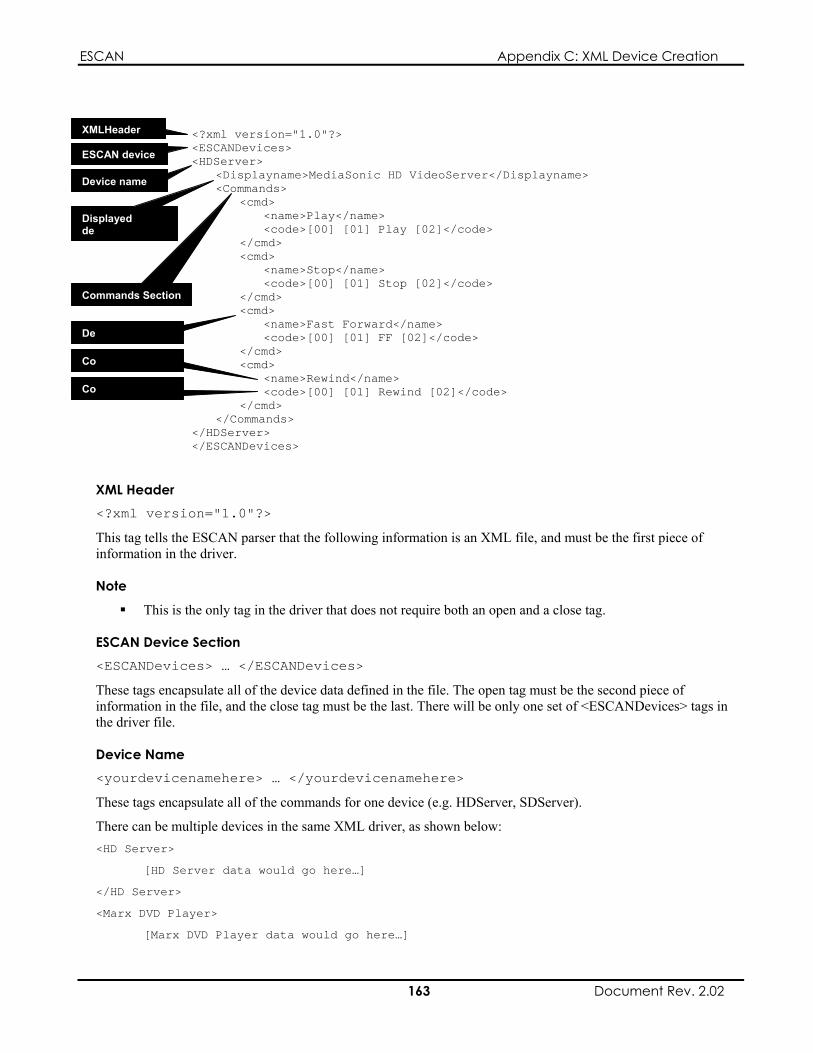
ESCAN Appendix C: XML Device Creation
=" .0"?>
<HDServer> <Displayname>MediaSonic HD VideoServer</Displayname> <Commands>
me>Play</name>
cmd> <name>Stop</name> <code>[00] [01] Stop [02]</code>
<name>Fast Forward</name> <code>[00] [01] FF [02]</code>
</cmd>
</Commands> </HDServer> </ESCANDevices>
XML Header
This tag tells the ESCAN parser that the following information is an XML file, and must be the first piece of information in the driver.
tag in the driver that does not require both an open and a close tag.
ESCAN Device Section <ESCANDevices> … </ESCANDevices>
These tags encapsulate all of the device data defined in the file. The open tag must be the second piece of e close tag must be the last. There will be only one set of <ESCANDevices> tags in
the driver file.
Device Name <yourdevicenamehere> … </yourdevicenamehere>
These tags encapsulate all of the commands for one device (e.g. HDServer, SDServer).
<HD Server>
[HD Server data would go here…]
</HD Server>
<Marx DVD Player>
[Marx DVD Player data would go here…]
<?xml version 1<ESCANDevices>
<cmd> <na <code>[00] [01] Play [02]</code> </cmd> <
vice name
</cmd> <cmd>
vice command
XMLHeader
Commands Section
De
Device name
ESCAN device
Displayed de
<cmd> mmand name <name>Rewind</name> <code>[00] [01] Rewind [02]</code> </cmd>
mmand code
Co
Co
<?xml version="1.0"?>
Note
This is the only
information in the file, and th
There can be multiple devices in the same XML driver, as shown below:
163 Document Rev. 2.02

ESCAN Appendix C: XML Device Creation
</Marx DVD Player>
etc.
Displayed Device Name <Displayname> … </Displayname>
These tags define the name that will show up in the ESCAN’s Add Device dialog box. For example, the following text in the driver: <Displayname> MediaSonic HD VideoServer </Displayname>
would cause the device to appear in ESCAN’s Add device dialog box like this:
XML Device Driver Appearing in ESCAN Device List
One set of <Displayname> tags will exist for each device in the driver file.
Commands Section <Commands> … </Commands>
These tags encapsulate all the commands for a given device. One set of <Commands> tags will exist for each device in the driver file.
Device Command <cmd> … </cmd>
These tags define an individual command for a device, and encapsulate one set of <name> tags and one set of <code> tags, as shown below: <cmd> <name>Play</name> <code>[00] [01] Play [02]</code>
</cmd>
There will typically be multiple sets of <cmd> tags within each set of <Commands> tags, as most devices will require more than one control command for full functionality.
Command Name <name> … </name>
These tags define the name for the associated Device Command. The text placed between these tags is the text that will identify the command when creating cues for the device in a Sequence or Schedule.
For example, the following text in the driver: <name>Play</name>
164 Document Rev. 2.02

ESCAN Appendix C: XML Device Creation
would cause the device to appear in ESCAN’s Edit XMLImportDevice dialog box like this:
XML Device Driver Command List
There can be only one set of <name> tags within each set of <cmd> tags.
Command Code <code> … </code>
These tags define the actual code that is sent when ESCAN releases the cue. Hexadecimal data is sent by enclosing each hex pair in brackets. Any data outside of a bracket pair will be sent as ASCII characters.
The following text in the driver <code> [00] [01] Play [02] </code>
Would cause the following hex data to be sent (the spaces are included for readability only):
00 01 50 6C 61 79 02
There can be only one set of <code> tags within each set of <cmd> tags.
Troubleshooting
If your devices do not appear in ESCAN after creating your driver file, here are some tips to get you back on track:
Make sure Internet Explorer version 6.0 is installed on your ESCAN computer. The XML tags are case sensitive. Verify your tags against the examples shown above. For the Device
Name tag, even though you can chose its content, make sure the case is consistent across the open and close tags; using <HDServer> for an open tag and </hdserver> for a close tag will not yield the correct results.
Open the driver file in Internet Explorer; you should be able to expand and collapse the various levels of your driver file. If a level appears “stuck”, check your code for a mistyped (or missing) tag.
165 Document Rev. 2.02

ESCAN Appendix C: XML Device Creation
This page intentionally left blank.
166 Document Rev. 2.02

ESCAN Index
Index
A
Add Device dialog box ................................ 60 Add New Trigger Group dialog box............ 98 Add New Trigger/Edit Selected Trigger dialog
box............................................................ 99 Triggered Device region
Device field........................................ 100 Triggering Device region
Action field ........................................ 100 Device field.......................................... 99 Trigger field ......................................... 99
Add New Variables Group dialog box....... 119 AT EXT time type ....................................... 71 AT time type ................................................ 71 AT X time type ............................................ 71 Autoexec sequence....................................... 78
C
Comm Timeouts dialog box......................... 54 Comms branch
accessing the Comms branch ................... 49 Comms branch menu ................................... 52
Add Comm Port option............................ 53 Close All Ports option.............................. 53 Open All Ports option .............................. 53
Comms icon representation.................... 51, 56 Comms overview ......................................... 49 Comms port menu........................................ 55
Close Port option...................................... 56 Delete Comm Port option ........................ 55 Open Port option...................................... 55 Properties option ...................................... 55
Comms ports closing ports
closing a single port ............................. 51 closing all ports .................................... 51
RS-232 ports ........................................ 49 deleting ports............................................ 52 opening ports
opening a single port............................ 51 opening all ports................................... 51
viewing/editing port properties ................ 52 Communication Port Settings dialog box .... 53
Name field................................................ 53 RS-232 region .......................................... 53 TCP/IP region .......................................... 54
Create Day Schedule dialog box.................. 86 Create New Sequence dialog box ................ 69 cue times, changing in a Sequence cue........ 77
D
167 Document Rev. 2.02
configuring ports...................................... 49 Ethernet ports ....................................... 50
Define Variable dialog box........................ 121 Name field.............................................. 121 Type field ............................................... 121
Device branch menu .................................... 59 Add Device option ................................... 60
Device driver file extensions ..................... 161 DDK drivers........................................... 161 XML drivers........................................... 161
Device drivers, creating ............................. 161 using ESCAN DDK ............................... 161 using XML............................................. 161
Device drivers, overview ........................... 161 Device icon representation........................... 62 Device keyboard hotkeys............................. 63 Device menu ................................................ 60
Connect Device option............................. 61 Delete Device option................................ 61 Disconnect Device option ........................ 61 Monitor Device Comm option................. 61 Properties option ...................................... 61 Rename option ......................................... 61
Device menu selections................................ 63 Device toolbar buttons ................................. 63 Device, changing in a Sequence cue............ 77 Devices

ESCAN Index
connecting devices connecting a single device ................... 59 connecting all devices .......................... 59
defining a device ...................................... 57 deleting a device ...................................... 58 disconnecting devices
disconnecting a single device............... 59 disconnecting all devices ..................... 59
viewing/editing device properties ............ 58 Devices branch
accessing the Devices branch................... 57 Devices overview......................................... 57
E
Edit Schedule dialog box ............................. 73 Edit Variables Cue dialog box ................... 122
Operator Selector ............................... 124
Variable option............................... 123
Device Control button.................... 127
Variable option............................... 126
Test tab
device property option ................... 126 Enter VideoServer Cue dialog box ............ 144
Channel list ............................................ 145
Ethernet communication ............................ 147
F
Change tab ............................................. 122 Operand region................................... 124
Device Property option .................. 124 Value option................................... 124 Variable option............................... 124
Set region ........................................... 123 Device Property option .................. 123
Test tab................................................... 125 Device to Control region.................... 127
Device selector............................... 127 If region.............................................. 125
Variable option............................... 125 Operand region................................... 126
Device Property option .................. 126 Value option................................... 126
Operator selector................................ 126 Edit Variables Cue Dialog Box
If region
Command selector ................................. 144 Parameter field ....................................... 145 Select All Channels option..................... 145
ES4148 time code cable............................. 157 ESCAN
functionality levels................................... 11 ESCAN EL........................................... 11 ESCAN PL16....................................... 11 ESCAN UL .......................................... 11
installing................................................... 12 registration
entering the license key........................ 15 gathering and submitting registration
information....................................... 14 system requirements................................. 11
ESCAN Configuration dialog box............... 22 frame rate tab ........................................... 22 licensing tab ............................................. 23 log files directory tab ............................... 22 logging options tab................................... 22
ESCAN software elements Log window ............................................. 19 main application window......................... 18 main menu................................................ 18 main toolbar ............................................. 19 window area ............................................. 19 Workspace tree......................................... 19
viewing and hiding............................... 19 from menu........................................ 19 from toolbar ..................................... 19
Ethernet (as compared to RS-232)............. 147
frame rate, configuring for time code ........ 157 frame rate, setting......................................... 32
H
Halt Cue, adding to a Sequence ................... 97 Halt Ext time type .................................. 71, 94 Halt time type......................................... 71, 94 Halt Until time type ............................... 71, 94
I
installation.................... See ESCAN, installing
168 Document Rev. 2.02

ESCAN Index
IP address class names............................................. 148
IP address construction .............................. 148 host identifier ......................................... 148 network identifier................................... 148
IP address, accessing Windows 2000 ....................................... 152 Windows 98 ........................................... 150 Windows NT.......................................... 151
IP address, Choosing.................................. 148 on an existing network ........................... 149 on an independent network .................... 149
L
log files.................................... See System Log Log window ....See ESCAN software elements,
Log window
N
new file, creating.......................................... 32
P
PC2005 time code card .............................. 157 ping
defined.................................................... 154 performing a ping................................... 154
successful pings ................................. 155 unsuccessful pings ............................. 155
Play List Area menu................................... 143 Add Clip option...................................... 143 Delete All Clips option .......................... 144 Delete Clip option .................................. 144 Edit Clip option...................................... 144 Insert Clip option ................................... 143
Play List Options menu.............................. 141 Copy Playlist option............................... 142 Delete all option..................................... 142 Delete Playlist option............................. 142 Export Playlist option ............................ 143 Import Playlist option ............................ 143 New Playlist option................................ 142
Play List window ....................................... 140
Play List Area ........................................ 141 Play List Options button ........................ 141 Play List selector.................................... 141
R
registration ................See ESCAN, registration RS-232 (as compared to Ethernet)............. 147
S
saving ........................................................... 32 Schedule menu............................................. 89
Add Schedule option................................ 89 Copy Schedule option .............................. 90 Delete Schedule option ............................ 89 Edit Schedule option ................................ 89 Run Schedule option ................................ 90 Suspend Schedule option ......................... 90
Schedule priority.......................................... 81 Scheduler
activating............................................ 21, 84 keyboard hotkeys ..................................... 23 menu selections........................................ 23 overview................................................... 21 toolbar buttons ......................................... 23
Scheduler Devices........................................ 62 Schedules
copying a Schedule .................................. 83 creating a Schedule .................................. 82 deleting a cue in a Schedule..................... 84 deleting a Schedule .................................. 84 running a Schedule................................... 84 suspending a Schedule ............................. 85 viewing/editing a Schedule ...................... 83
Schedules branch accessing the Schedules branch ............... 82
Schedules branch menu................................ 85 Add Schedule option................................ 86
Schedules cue menu..................................... 90 Add Cue After Selected Row Option....... 90 Add Cue Before Selected Row Option .... 90
Schedules icon representation...................... 90 Schedules keyboard hotkeys ........................ 91 Schedules menu selections........................... 91 Schedules overview ..................................... 81
169 Document Rev. 2.02
ESCAN Index
Schedules window ....................................... 86 cue area .................................................... 87 Cue Description field ............................... 89 cue status indicator................................... 87 Device/Sequence field ............................. 88 run time indicator..................................... 87 Sequence Number field............................ 88 Time field................................................. 88
entering a time value............................ 88 tool bar ..................................................... 87 wait time indicator ................................... 87
Schedules, running individual...................... 81 Sequence Cue menu..................................... 75
Add Cue After Selected Row option ....... 76 Add Cue Before Selected Row option ..... 75 Change Device option.............................. 77 Change Time option................................. 76 Change Time Type option ....................... 76 Delete Selected Cue(s) option.................. 76 Disable/Enable Selected Cue option........ 77 Set Selected Row as Default option......... 76
Sequence icon representation....................... 78 Sequence keyboard hotkeys......................... 79 Sequence menu ............................................ 74
Add Sequence option ............................... 74 Copy Sequence option ............................. 74 Delete Sequence option............................ 74 Rename option ......................................... 74 Run Sequence From Pointer option ......... 75 Run Sequence option ............................... 74 Stop Sequence Option.............................. 75
Sequence menu Edit Sequence option ............................... 74
Sequence menu selections............................ 78 Sequence window ........................................ 69
cue area .................................................... 70 Cue Description field ............................... 72 Cue Number field..................................... 71 cue status indicator................................... 70 Device field.............................................. 72 run time indicator..................................... 70 Time field................................................. 71
entering a time value............................ 72 Time Type field........................................ 71 tool bar ..................................................... 70 wait time indicator ................................... 70
Sequences copying a Sequence.................................. 66 creating a Sequence.................................. 65 deleting a cue in a Sequence .................... 67 deleting a Sequence.................................. 67 overview................................................... 65 running a Sequence .................................. 68 stopping a Sequence................................. 68 viewing/editing a Sequence ..................... 67
Sequences branch accessing the Sequences branch............... 65
Sequences branch menu............................... 69 Add Sequence option ............................... 69
Startup sequence .......................................... 78 subnet mask................................................ 149 subnet mask, accessing
Windows 2000 ....................................... 152 Windows 98 ........................................... 150 Windows NT.......................................... 151
System Log log file
log file data .......................................... 28 log file location .................................... 27 log file names....................................... 28 viewing log files................................... 28
log file management................................. 28 log file size........................................... 28 managing log files with schedules . 28, 81
log files overview..................................... 26 log window............................................... 25
viewing and hiding the log window..... 26 logging options......................................... 26
accessing the log options ..................... 26 available options .................................. 27 setting log options ................................ 27
overview................................................... 25 types of logged data ................................. 25
T
TCP/IP addressing ..................................... 147 dynamic assignment....................... 148, 154
setting the IP address ..................... 154 Saving the subnet mask and IP address
values ............................................. 154 static assignment ............................ 147, 154
170 Document Rev. 2.02

ESCAN Index
saving the subnet mask and IP address values ............................................. 154
setting the IP address ......................... 154 setting the subnet mask ...................... 154
time code generating............................................... 158
starting time code generation ............. 158 stopping time code generation ........... 158
receiving................................................. 158 Time Type, changing in a Sequence cue ..... 76 Trigger Group menu .................................. 100
Delete Trigger Group option.................. 101 Edit Trigger Group option ..................... 101 Rename option ....................................... 101
Trigger Groups............................................. 93 adding a Trigger Group............................ 95 adding a Trigger to a Trigger Group........ 96 deleting a Trigger Group.......................... 96 editing a Trigger in a Trigger Group........ 97 viewing/editing a Trigger Group ............. 95
Trigger menu.............................................. 101 Add Row option..................................... 101 Cancel option ......................................... 102 Delete Selected Row option................... 101 Edit Selected Row option....................... 101
Trigger menu selection .............................. 102 Trigger parameter mapping........................ 100 Triggering Devices....................................... 93 Triggers branch
accessing the Triggers branch.................. 95 Triggers branch menu .................................. 97
Add Trigger Group option ....................... 98 Triggers overview ........................................ 93 Triggers to release cues................................ 94 Triggers window .......................................... 98
Action field .............................................. 99 Device field.............................................. 99 Event field................................................ 99 tool bar ..................................................... 98 trigger area ............................................... 98 Triggered Device field ............................. 99
Triggers, adding to a Trigger Group ...........See Trigger Groups, adding a Trigger to a Trigger Group
Tutorials
ESCAN Tutorial (Comms, Device, Sequences, and Schedules) ............ 31–48 adding devices...................................... 35 communications ports, configuring ..... 33 creating a new file................................ 32 creating a schedule............................... 43 creating the tutorial .............................. 31 defining sequences ............................... 38 frame rate, setting................................. 32 reviewing log activity .......................... 47 running the schedule ............................ 46 saving the filel...................................... 32
Variable Tutorial, Device properties 110–17 comms ports definition ...................... 111 creating a new file.............................. 110 creating the AMX handler sequence.. 113 creating the AMX trigger group ........ 113 device definition................................. 111 finishing the AMX handler sequence 114 saving the file..................................... 111 setting the frame rate.......................... 111
Variable Tutorial, loop counters ...... 104–10 comparing the variable’s value .......... 108 creating a new file.............................. 104 creating a variable group.................... 105 creating the final cue.......................... 109 defining a global variable................... 105 saving the file..................................... 104 setting the frame rate.......................... 105 setting the global variable’s value...... 106 testing the loop................................... 110
VideoServer control ......................... 129–40 configuring the VideoServer’s comms
port ................................................. 130 creating a new file.............................. 129 creating play lists ............................... 133 creating VideoServer sequences ........ 135 defining the VideoServer device........ 131 saving the file..................................... 130 setting the frame rate.......................... 130
V
Variable Group menu................................. 121 Delete Variable Group option................ 121 Edit Variable Group option.................... 121
171 Document Rev. 2.02

ESCAN Index
Rename option ....................................... 122 Variable Groups
adding a Variable group......................... 118 adding a Variable to a Variable group ... 118 editing a Variable in a Variable group... 119 viewing/editing a Variable group........... 118
Variable menu............................................ 122 Add Row option..................................... 122 Cance option .......................................... 122 Delete Selected Row option................... 122 Edit Selected Row option....................... 122
variable tutorials...........See Tutorials, variable tutorials
Variables branch accessing the Variables branch .............. 117
Variables branch menu .............................. 119 Add Variable Group option ................... 119
Variables Devices ........................................ 62 Variables menu selections.......................... 127 Variables overview .................................... 103 Variables window ...................................... 120
tool bar ................................................... 120 Type field ............................................... 120 Variable Name field............................... 120 Variables area......................................... 120
Variables, steps involved in using ............. 103 comparing variables ............................... 103
creating variable groups......................... 103 defining variables................................... 103 device property variables ....................... 104 setting variable values............................ 103
W
Wait time type.............................................. 71 Workspace tree.SeeESCAN software elements,
Workspace tree
X
XML device driver troubleshooting........... 165 XML Device drivers .................................. 162
file authoring.......................................... 162 XML driver structure ................................. 162
command code ....................................... 165 command name ...................................... 164 commands section.................................. 164 device command .................................... 164 device name ........................................... 163 displayed device name ........................... 164 ESCAN device section........................... 163 XML Header .......................................... 163
172 Document Rev. 2.02