es630.1/ es635.1 lambda module (1-ch) es631.1/ es636.1 ... · es630.1/ es635.1 lambda module (1-ch)...
TRANSCRIPT

ES630.1/ ES635.1 Lambda Module (1-CH)ES631.1/ ES636.1 Lambda Module (2-CH)User’s Guide

2
Copyright
The data in this document may not be altered or amended without special noti-fication from ETAS GmbH. ETAS GmbH undertakes no further obligation in rela-tion to this document. The software described in it can only be used if thecustomer is in possession of a general license agreement or single license. Usingand copying is only allowed in concurrence with the specifications stipulated inthe contract.
Under no circumstances may any part of this document be copied, reproduced,transmitted, stored in a retrieval system or translated into another languagewithout the express written permission of ETAS GmbH.
© Copyright 2018 ETAS GmbH, Stuttgart
The names and designations used in this document are trademarks or brandsbelonging to the respective owners.
ES63x - User’s Guide R06 EN - 04.2018

Contents
ETAS Contents
1 About this Manual . . . . . . . . . . . . . . . . . . . . . . . . . . . . . . . . . . . . . . . . . . . . . . . . 101.1 Identification of safety notices . . . . . . . . . . . . . . . . . . . . . . . . . . . . . . . . . . 101.2 Presentation of information . . . . . . . . . . . . . . . . . . . . . . . . . . . . . . . . . . . . 111.3 Scope of supply . . . . . . . . . . . . . . . . . . . . . . . . . . . . . . . . . . . . . . . . . . . . . 111.4 Additional information . . . . . . . . . . . . . . . . . . . . . . . . . . . . . . . . . . . . . . . . 11
2 Basic Safety Notices . . . . . . . . . . . . . . . . . . . . . . . . . . . . . . . . . . . . . . . . . . . . . . . 122.1 General Safety Information . . . . . . . . . . . . . . . . . . . . . . . . . . . . . . . . . . . . . 122.2 Requirements for Users and Duties for Operators . . . . . . . . . . . . . . . . . . . . 122.3 Intended Use . . . . . . . . . . . . . . . . . . . . . . . . . . . . . . . . . . . . . . . . . . . . . . . 12
3 Hardware Description . . . . . . . . . . . . . . . . . . . . . . . . . . . . . . . . . . . . . . . . . . . . . . 173.1 Lambda Modules . . . . . . . . . . . . . . . . . . . . . . . . . . . . . . . . . . . . . . . . . . . . 17
3.1.1 Measure Values . . . . . . . . . . . . . . . . . . . . . . . . . . . . . . . . . . . . . . . 183.1.2 Features . . . . . . . . . . . . . . . . . . . . . . . . . . . . . . . . . . . . . . . . . . . . 19
3.2 Housing . . . . . . . . . . . . . . . . . . . . . . . . . . . . . . . . . . . . . . . . . . . . . . . . . . . 203.2.1 Front of Device . . . . . . . . . . . . . . . . . . . . . . . . . . . . . . . . . . . . . . . 203.2.2 Rear of Device . . . . . . . . . . . . . . . . . . . . . . . . . . . . . . . . . . . . . . . . 20
3.3 Block Diagram . . . . . . . . . . . . . . . . . . . . . . . . . . . . . . . . . . . . . . . . . . . . . . 243.4 Measurement Channel . . . . . . . . . . . . . . . . . . . . . . . . . . . . . . . . . . . . . . . . 24
3.4.1 Signal Processing and Filters . . . . . . . . . . . . . . . . . . . . . . . . . . . . . 243.4.2 Pressure Compensation . . . . . . . . . . . . . . . . . . . . . . . . . . . . . . . . . 253.4.3 Heater Control . . . . . . . . . . . . . . . . . . . . . . . . . . . . . . . . . . . . . . . 263.4.4 Analog Output "VOUT" . . . . . . . . . . . . . . . . . . . . . . . . . . . . . . . . 26
3.5 Sensor Identification (TEDS) . . . . . . . . . . . . . . . . . . . . . . . . . . . . . . . . . . . . 263.5.1 Sensor Cable with Cable Identification (TEDS) . . . . . . . . . . . . . . . . 263.5.2 Lambda Sensor with Sensor Identification (TEDS) . . . . . . . . . . . . . . 26
3.6 Sensor Cable . . . . . . . . . . . . . . . . . . . . . . . . . . . . . . . . . . . . . . . . . . . . . . . 263.7 Data Transfer via Ethernet . . . . . . . . . . . . . . . . . . . . . . . . . . . . . . . . . . . . . . 27
ES63x - User’s Guide 3

4
Contents ETAS
3.7.1 Communication Protocols . . . . . . . . . . . . . . . . . . . . . . . . . . . . . . . 273.7.2 Realization . . . . . . . . . . . . . . . . . . . . . . . . . . . . . . . . . . . . . . . . . . 283.7.3 Examples . . . . . . . . . . . . . . . . . . . . . . . . . . . . . . . . . . . . . . . . . . . . 30
3.8 Data Transfer via SMB . . . . . . . . . . . . . . . . . . . . . . . . . . . . . . . . . . . . . . . . . 323.8.1 Request PC ES63x . . . . . . . . . . . . . . . . . . . . . . . . . . . . . . . . . . . 323.8.2 Response ES63x PC. . . . . . . . . . . . . . . . . . . . . . . . . . . . . . . . . . 323.8.3 Code Table of SMB . . . . . . . . . . . . . . . . . . . . . . . . . . . . . . . . . . . . 32
3.9 Power Supply . . . . . . . . . . . . . . . . . . . . . . . . . . . . . . . . . . . . . . . . . . . . . . . 323.9.1 Supply Voltage of the ES63x Modules . . . . . . . . . . . . . . . . . . . . . . 333.9.2 Power Supply to ES63x Modules linked by Ethernet . . . . . . . . . . . . 333.9.3 Power Supply to ES63x Modules linked by SMB. . . . . . . . . . . . . . . 343.9.4 Supply Voltage of the Lambda Sensor . . . . . . . . . . . . . . . . . . . . . . 34
4 Functional Description. . . . . . . . . . . . . . . . . . . . . . . . . . . . . . . . . . . . . . . . . . . . . . 354.1 Broadband Lambda Sensors . . . . . . . . . . . . . . . . . . . . . . . . . . . . . . . . . . . . 354.2 Operating Modes of the Measurement System . . . . . . . . . . . . . . . . . . . . . . 35
4.2.1 Operational State “Normal” . . . . . . . . . . . . . . . . . . . . . . . . . . . . . 354.2.2 Operational State "Measurement channel Disabled, Sensor Heating
On”. . . . . . . . . . . . . . . . . . . . . . . . . . . . . . . . . . . . . . . . . . . . . . . . 364.3 Measure Values . . . . . . . . . . . . . . . . . . . . . . . . . . . . . . . . . . . . . . . . . . . . . 36
4.3.1 Overview. . . . . . . . . . . . . . . . . . . . . . . . . . . . . . . . . . . . . . . . . . . . 364.3.2 Output in the Calibration Software or on the Display. . . . . . . . . . . 374.3.3 Output at the Analog Output . . . . . . . . . . . . . . . . . . . . . . . . . . . . 374.3.4 Output at the “SERVICE” Port . . . . . . . . . . . . . . . . . . . . . . . . . . . . 37
4.4 Sensor Heating . . . . . . . . . . . . . . . . . . . . . . . . . . . . . . . . . . . . . . . . . . . . . . 384.4.1 Operating Modes . . . . . . . . . . . . . . . . . . . . . . . . . . . . . . . . . . . . . 384.4.2 Heater Control . . . . . . . . . . . . . . . . . . . . . . . . . . . . . . . . . . . . . . . 38
5 Getting Started . . . . . . . . . . . . . . . . . . . . . . . . . . . . . . . . . . . . . . . . . . . . . . . . . . . 405.1 General Installation Recommendations . . . . . . . . . . . . . . . . . . . . . . . . . . . . 40
5.1.1 Assembly Environment and Components for Attaching the Module 405.1.2 Potential Equalization in the Vehicle and Module Assembly . . . . . . 405.1.3 Fastening the Module onto a Carrier System . . . . . . . . . . . . . . . . . 405.1.4 Connecting several Modules Mechanically . . . . . . . . . . . . . . . . . . . 41
5.2 Installing the Lambda Sensor . . . . . . . . . . . . . . . . . . . . . . . . . . . . . . . . . . . 435.3 Assembling the Pressure Sensor . . . . . . . . . . . . . . . . . . . . . . . . . . . . . . . . . 46
5.3.1 Place of Installation . . . . . . . . . . . . . . . . . . . . . . . . . . . . . . . . . . . . 465.3.2 Thermal Isolation . . . . . . . . . . . . . . . . . . . . . . . . . . . . . . . . . . . . . . 465.3.3 Connecting with the Module. . . . . . . . . . . . . . . . . . . . . . . . . . . . . 47
5.4 Applications . . . . . . . . . . . . . . . . . . . . . . . . . . . . . . . . . . . . . . . . . . . . . . . . 485.4.1 ES63x Modules with ES4xx/ES600/ES720/ES910 and INCA. . . . . . . 485.4.2 ES63x Modules with ES4xx/ES720/ES910 and INTECRIO. . . . . . . . . 50
5.5 Wiring . . . . . . . . . . . . . . . . . . . . . . . . . . . . . . . . . . . . . . . . . . . . . . . . . . . . 515.5.1 Power Supply to ES63x Modules linked by Ethernet . . . . . . . . . . . . 515.5.2 Power Supply to ES63x Modules linked by SMB. . . . . . . . . . . . . . . 525.5.3 Daisy Chain Ports (“IN”, “OUT”) . . . . . . . . . . . . . . . . . . . . . . . . . . 535.5.4 “LAMBDA” Port . . . . . . . . . . . . . . . . . . . . . . . . . . . . . . . . . . . . . . 545.5.5 “VOUT” Port . . . . . . . . . . . . . . . . . . . . . . . . . . . . . . . . . . . . . . . . . 54
5.6 Tool Integration . . . . . . . . . . . . . . . . . . . . . . . . . . . . . . . . . . . . . . . . . . . . . 54
ES63x - User’s Guide
ETAS Contents
5.7 Configuration . . . . . . . . . . . . . . . . . . . . . . . . . . . . . . . . . . . . . . . . . . . . . . . 555.7.1 Configuring the Lambda Module. . . . . . . . . . . . . . . . . . . . . . . . . . 555.7.2 Configuring the Lambda Sensor . . . . . . . . . . . . . . . . . . . . . . . . . . 555.7.3 Calibrating the Lambda Sensor LSU ADV-D . . . . . . . . . . . . . . . . . . 55
5.8 Calibration . . . . . . . . . . . . . . . . . . . . . . . . . . . . . . . . . . . . . . . . . . . . . . . . . 55
6 Configuration at the Module . . . . . . . . . . . . . . . . . . . . . . . . . . . . . . . . . . . . . . . . 566.1 Configuration in the Calibration Software and at the Module . . . . . . . . . . . 56
6.1.1 Function Keys . . . . . . . . . . . . . . . . . . . . . . . . . . . . . . . . . . . . . . . . 566.1.2 Keys . . . . . . . . . . . . . . . . . . . . . . . . . . . . . . . . . . . . . . . . . . . . . . . 57
6.2 Display . . . . . . . . . . . . . . . . . . . . . . . . . . . . . . . . . . . . . . . . . . . . . . . . . . . . 576.2.1 Displaying in the Operating Mode “Measuring” . . . . . . . . . . . . . . 576.2.2 Displaying in the Operating Mode “Configuration” . . . . . . . . . . . . 59
6.3 Calling Menus and Submenus . . . . . . . . . . . . . . . . . . . . . . . . . . . . . . . . . . . 606.3.1 Switching to the Operating Mode “Configuration” . . . . . . . . . . . . 606.3.2 Selecting a Menu Item. . . . . . . . . . . . . . . . . . . . . . . . . . . . . . . . . . 606.3.3 Changing Numerical Parameter Values of a Menu Item . . . . . . . . . 606.3.4 Exiting a Menu Item / Menu Level . . . . . . . . . . . . . . . . . . . . . . . . . 616.3.5 Switching Between “Standard” and “Advanced” . . . . . . . . . . . . . 616.3.6 Switching to the Operating Mode “Measuring” . . . . . . . . . . . . . . 626.3.7 Displaying the Error Text . . . . . . . . . . . . . . . . . . . . . . . . . . . . . . . . 62
6.4 Configuration Menu . . . . . . . . . . . . . . . . . . . . . . . . . . . . . . . . . . . . . . . . . . 626.4.1 Operating Modes . . . . . . . . . . . . . . . . . . . . . . . . . . . . . . . . . . . . . 626.4.2 Operating Modes and Measurement Channels . . . . . . . . . . . . . . . 626.4.3 Adjustable Parameters . . . . . . . . . . . . . . . . . . . . . . . . . . . . . . . . . . 63
7 Setting the Parameters (“Standard” Operating Mode). . . . . . . . . . . . . . . . . . . . . . 647.1 [Menu 1]: sensor presets: Display of the Configurations of the Lambda Sensor
657.2 [Menu 2]: analog out: Output Voltage at the Analog Output . . . . . . . . . . . 667.3 [Menu 3]: signal on display . . . . . . . . . . . . . . . . . . . . . . . . . . . . . . . . . . . . . 677.4 [Menu 4|1]: channel / pressure comp.: Automatic Pressure Compensation . 687.5 [Menu 4|2]: channel / sensor detection . . . . . . . . . . . . . . . . . . . . . . . . . . . . 69
7.5.1 Sensor Detection: off. . . . . . . . . . . . . . . . . . . . . . . . . . . . . . . . . . . 697.5.2 Sensor Detection: on . . . . . . . . . . . . . . . . . . . . . . . . . . . . . . . . . . . 697.5.3 Sensor Detection: userdef. defaults . . . . . . . . . . . . . . . . . . . . . . . . 69
7.6 [Menu 5]: other . . . . . . . . . . . . . . . . . . . . . . . . . . . . . . . . . . . . . . . . . . . . . 707.6.1 [Menu 5|1]: other / display. . . . . . . . . . . . . . . . . . . . . . . . . . . . . . . 707.6.2 [Menu 5|3]: other / dev. mode: Operating Modes . . . . . . . . . . . . . 747.6.3 [Menu 5|4]: other / factory init: Default Configuration . . . . . . . . . . 757.6.4 [Menu 5|5]: other / version: Displaying Firmware Version and Serial
Numbers . . . . . . . . . . . . . . . . . . . . . . . . . . . . . . . . . . . . . . . . . . . . 75
8 Setting the Parameters (“Advanced” Operating Mode) . . . . . . . . . . . . . . . . . . . . . 768.1 [Menu 1]: sensor presets: Assigning a Configuration for the Lambda Sensor 768.2 [Menu 4|3]: channel / mode l: Determining the Calculation Process . . . . . . . 78
8.2.1 [Menu 4|3|1] : channel / mode l / line: Selecting a Lambda Line . . . 788.2.2 [Menu 4|3|2] : channel / mode l / analytic: Adapting Fuel and Environ-
ment . . . . . . . . . . . . . . . . . . . . . . . . . . . . . . . . . . . . . . . . . . . . . . . 79
ES63x - User’s Guide 5

6
Contents ETAS
8.2.3 [Menu 4|3|3]: channel / mode l / advanced: Adapting Combustion and Sensor . . . . . . . . . . . . . . . . . . . . . . . . . . . . . . . . . . . . . . . . . . . . . . 80
8.3 [Menu 4|4]: channel / heater line . . . . . . . . . . . . . . . . . . . . . . . . . . . . . . . . 878.4 [Menu 4|5]: channel / temperature line . . . . . . . . . . . . . . . . . . . . . . . . . . . . 878.5 [Menu 4|6]: channel / operating parameters . . . . . . . . . . . . . . . . . . . . . . . . 88
9 Instructions and Sample Calculations . . . . . . . . . . . . . . . . . . . . . . . . . . . . . . . . . . 899.1 Measuring the Sensor Curve . . . . . . . . . . . . . . . . . . . . . . . . . . . . . . . . . . . . 89
9.1.1 Sensor Curve in the Lean Range: lean scale . . . . . . . . . . . . . . . . . . 909.1.2 Sensor Curve in Rich Range: rich scale . . . . . . . . . . . . . . . . . . . . . . 919.1.3 Sensor Curve in Zero Current Range: zero offset . . . . . . . . . . . . . . 92
9.2 Calibrate to Air . . . . . . . . . . . . . . . . . . . . . . . . . . . . . . . . . . . . . . . . . . . . . . 939.3 Parameterizing the Analog Output Voltage . . . . . . . . . . . . . . . . . . . . . . . . . 94
9.3.1 Calculating the Offset and Gain Parameters. . . . . . . . . . . . . . . . . . 949.3.2 Examples of Offset and Gain . . . . . . . . . . . . . . . . . . . . . . . . . . . . . 94
9.4 Sample Calculations . . . . . . . . . . . . . . . . . . . . . . . . . . . . . . . . . . . . . . . . . . 969.4.1 Fuel Composition . . . . . . . . . . . . . . . . . . . . . . . . . . . . . . . . . . . . . 96
10 Technical Data . . . . . . . . . . . . . . . . . . . . . . . . . . . . . . . . . . . . . . . . . . . . . . . . . . . 9810.1 General Data . . . . . . . . . . . . . . . . . . . . . . . . . . . . . . . . . . . . . . . . . . . . . . . 98
10.1.1 Product labeling . . . . . . . . . . . . . . . . . . . . . . . . . . . . . . . . . . . . . . 9810.1.2 Standards and Norms . . . . . . . . . . . . . . . . . . . . . . . . . . . . . . . . . . 9910.1.3 Environmental Conditions . . . . . . . . . . . . . . . . . . . . . . . . . . . . . 10010.1.4 Maintenance the Product . . . . . . . . . . . . . . . . . . . . . . . . . . . . . . 10010.1.5 Cleaning the product. . . . . . . . . . . . . . . . . . . . . . . . . . . . . . . . . . 10010.1.6 Mechanical Data . . . . . . . . . . . . . . . . . . . . . . . . . . . . . . . . . . . . . 100
10.2 RoHS Conformity . . . . . . . . . . . . . . . . . . . . . . . . . . . . . . . . . . . . . . . . . . . 10110.2.1 European Union . . . . . . . . . . . . . . . . . . . . . . . . . . . . . . . . . . . . . 10110.2.2 China . . . . . . . . . . . . . . . . . . . . . . . . . . . . . . . . . . . . . . . . . . . . . 101
10.3 CE Labeling . . . . . . . . . . . . . . . . . . . . . . . . . . . . . . . . . . . . . . . . . . . . . . . 10110.4 Taking the Product Back and Recycling . . . . . . . . . . . . . . . . . . . . . . . . . . . 10110.5 Declarable Substances . . . . . . . . . . . . . . . . . . . . . . . . . . . . . . . . . . . . . . . 10210.6 Use of Open Source software . . . . . . . . . . . . . . . . . . . . . . . . . . . . . . . . . . 10210.7 System Requirements . . . . . . . . . . . . . . . . . . . . . . . . . . . . . . . . . . . . . . . . 102
10.7.1 Hardware . . . . . . . . . . . . . . . . . . . . . . . . . . . . . . . . . . . . . . . . . . 10210.7.2 Supported Applications and Software Requirements . . . . . . . . . . 103
10.8 Electrical Data . . . . . . . . . . . . . . . . . . . . . . . . . . . . . . . . . . . . . . . . . . . . . . 10410.8.1 Measurement Category . . . . . . . . . . . . . . . . . . . . . . . . . . . . . . . . 10410.8.2 Measurement Accuracy . . . . . . . . . . . . . . . . . . . . . . . . . . . . . . . 10410.8.3 Host Interface (Ethernet) . . . . . . . . . . . . . . . . . . . . . . . . . . . . . . 10410.8.4 Host Interface (RS232) . . . . . . . . . . . . . . . . . . . . . . . . . . . . . . . . . 10510.8.5 Power Supply . . . . . . . . . . . . . . . . . . . . . . . . . . . . . . . . . . . . . . . 10610.8.6 Display . . . . . . . . . . . . . . . . . . . . . . . . . . . . . . . . . . . . . . . . . . . . 10610.8.7 Signal Processing . . . . . . . . . . . . . . . . . . . . . . . . . . . . . . . . . . . . . 10710.8.8 Analog Output "VOUT" . . . . . . . . . . . . . . . . . . . . . . . . . . . . . . . 10910.8.9 EXTEN - External Signal . . . . . . . . . . . . . . . . . . . . . . . . . . . . . . . . 11010.8.10 Sensor Port . . . . . . . . . . . . . . . . . . . . . . . . . . . . . . . . . . . . . . . . . 11010.8.11 Pressure Sensor Port "EPS" . . . . . . . . . . . . . . . . . . . . . . . . . . . . . 11110.8.12 Pressure Sensor PS63. . . . . . . . . . . . . . . . . . . . . . . . . . . . . . . . . . 111
ES63x - User’s Guide

ETAS Contents
10.9 Pin Assignment . . . . . . . . . . . . . . . . . . . . . . . . . . . . . . . . . . . . . . . . . . . . 11210.9.1 “IN” Connector. . . . . . . . . . . . . . . . . . . . . . . . . . . . . . . . . . . . . . 11210.9.2 “OUT” Connector . . . . . . . . . . . . . . . . . . . . . . . . . . . . . . . . . . . . 11310.9.3 “Sensor” Connector . . . . . . . . . . . . . . . . . . . . . . . . . . . . . . . . . . 11410.9.4 „Analog“ Connector . . . . . . . . . . . . . . . . . . . . . . . . . . . . . . . . . . 11510.9.5 „EPS“ Connector (ES635.1 and ES636.1). . . . . . . . . . . . . . . . . . . 11510.9.6 „SERVICE“ Connector . . . . . . . . . . . . . . . . . . . . . . . . . . . . . . . . . 115
11 Cables and Accessories . . . . . . . . . . . . . . . . . . . . . . . . . . . . . . . . . . . . . . . . . . . . 11611.1 Power Supply Cable . . . . . . . . . . . . . . . . . . . . . . . . . . . . . . . . . . . . . . . . . 117
11.1.1 Cable CBP630 . . . . . . . . . . . . . . . . . . . . . . . . . . . . . . . . . . . . . . . 11711.1.2 Cable CBP6305 . . . . . . . . . . . . . . . . . . . . . . . . . . . . . . . . . . . . . . 118
11.2 Combined Ethernet and Power Supply Cable . . . . . . . . . . . . . . . . . . . . . . 11911.2.1 Overview. . . . . . . . . . . . . . . . . . . . . . . . . . . . . . . . . . . . . . . . . . . 11911.2.2 CBEP410.1 Cable . . . . . . . . . . . . . . . . . . . . . . . . . . . . . . . . . . . . 12011.2.3 CBEP4105.1 Cable . . . . . . . . . . . . . . . . . . . . . . . . . . . . . . . . . . . 12011.2.4 CBEP415.1 Cable . . . . . . . . . . . . . . . . . . . . . . . . . . . . . . . . . . . . 12111.2.5 CBEP4155.1 Cable . . . . . . . . . . . . . . . . . . . . . . . . . . . . . . . . . . . 12111.2.6 CBEP420.1 Cable . . . . . . . . . . . . . . . . . . . . . . . . . . . . . . . . . . . . 12211.2.7 CBEP4205.1 Cable . . . . . . . . . . . . . . . . . . . . . . . . . . . . . . . . . . . 12211.2.8 CBEP425.1 Cable . . . . . . . . . . . . . . . . . . . . . . . . . . . . . . . . . . . . 12311.2.9 CBEP4255.1 Cable . . . . . . . . . . . . . . . . . . . . . . . . . . . . . . . . . . . 12311.2.10 CBEP430.1 Cable . . . . . . . . . . . . . . . . . . . . . . . . . . . . . . . . . . . . 12411.2.11 CBEP4305.1 Cable . . . . . . . . . . . . . . . . . . . . . . . . . . . . . . . . . . . 124
11.3 Ethernet Cable . . . . . . . . . . . . . . . . . . . . . . . . . . . . . . . . . . . . . . . . . . . . . 12511.3.1 CBE400.2 Cable . . . . . . . . . . . . . . . . . . . . . . . . . . . . . . . . . . . . . 12511.3.2 CBE401.1 Cable . . . . . . . . . . . . . . . . . . . . . . . . . . . . . . . . . . . . . 12511.3.3 CBE430.1 Cable . . . . . . . . . . . . . . . . . . . . . . . . . . . . . . . . . . . . . 12611.3.4 CBE431.1 Cable . . . . . . . . . . . . . . . . . . . . . . . . . . . . . . . . . . . . . 12611.3.5 CBEX400.1 Cable . . . . . . . . . . . . . . . . . . . . . . . . . . . . . . . . . . . . 126
11.4 SMB Cable . . . . . . . . . . . . . . . . . . . . . . . . . . . . . . . . . . . . . . . . . . . . . . . . 12711.4.1 K38 Cable . . . . . . . . . . . . . . . . . . . . . . . . . . . . . . . . . . . . . . . . . . 12711.4.2 K39 Cable . . . . . . . . . . . . . . . . . . . . . . . . . . . . . . . . . . . . . . . . . . 12711.4.3 K40 Cable . . . . . . . . . . . . . . . . . . . . . . . . . . . . . . . . . . . . . . . . . . 12811.4.4 CBAS100 Cable. . . . . . . . . . . . . . . . . . . . . . . . . . . . . . . . . . . . . . 128
11.5 Sensor Cables . . . . . . . . . . . . . . . . . . . . . . . . . . . . . . . . . . . . . . . . . . . . . . 12911.5.1 Lambda Sensors and associated Cables . . . . . . . . . . . . . . . . . . . . 13011.5.2 CBAL410.1 Cable . . . . . . . . . . . . . . . . . . . . . . . . . . . . . . . . . . . . 13111.5.3 CBAL4105.1 Cable . . . . . . . . . . . . . . . . . . . . . . . . . . . . . . . . . . . 13311.5.4 CBAL451.1 Cable . . . . . . . . . . . . . . . . . . . . . . . . . . . . . . . . . . . . 13511.5.5 CBAL4515.1 Cable . . . . . . . . . . . . . . . . . . . . . . . . . . . . . . . . . . . 13711.5.6 CBAL452.1 Cable . . . . . . . . . . . . . . . . . . . . . . . . . . . . . . . . . . . . 13911.5.7 CBAL4525.1 Cable . . . . . . . . . . . . . . . . . . . . . . . . . . . . . . . . . . . 14111.5.8 CBAL463.1 Cable . . . . . . . . . . . . . . . . . . . . . . . . . . . . . . . . . . . . 14311.5.9 CBAL4635.1 Cable . . . . . . . . . . . . . . . . . . . . . . . . . . . . . . . . . . . 14511.5.10 CBAL468.1 Cable . . . . . . . . . . . . . . . . . . . . . . . . . . . . . . . . . . . . 14711.5.11 CBAL4685.1 Cable . . . . . . . . . . . . . . . . . . . . . . . . . . . . . . . . . . . 14911.5.12 CBAL472.1 Cable . . . . . . . . . . . . . . . . . . . . . . . . . . . . . . . . . . . . 15111.5.13 CBAL4725.1 Cable . . . . . . . . . . . . . . . . . . . . . . . . . . . . . . . . . . . 153
ES63x - User’s Guide 7
8
Contents ETAS
11.6 Pressure Sensor and Accessories . . . . . . . . . . . . . . . . . . . . . . . . . . . . . . . . 15511.6.1 Pressure Sensor . . . . . . . . . . . . . . . . . . . . . . . . . . . . . . . . . . . . . . 15511.6.2 CBAX100.1 Cable . . . . . . . . . . . . . . . . . . . . . . . . . . . . . . . . . . . . 155
11.7 Protective Caps . . . . . . . . . . . . . . . . . . . . . . . . . . . . . . . . . . . . . . . . . . . . . 15611.7.1 Cap CAP_LEMO_1B. . . . . . . . . . . . . . . . . . . . . . . . . . . . . . . . . . . 15611.7.2 Cap CAP_LEMO_1B_LC. . . . . . . . . . . . . . . . . . . . . . . . . . . . . . . . 15711.7.3 Cap CAP_SOURIAU_8STA . . . . . . . . . . . . . . . . . . . . . . . . . . . . . . 157
12 Ordering Information . . . . . . . . . . . . . . . . . . . . . . . . . . . . . . . . . . . . . . . . . . . . . 15812.1 Lambda Module . . . . . . . . . . . . . . . . . . . . . . . . . . . . . . . . . . . . . . . . . . . 15812.2 Lambda Module Sets . . . . . . . . . . . . . . . . . . . . . . . . . . . . . . . . . . . . . . . . 159
12.2.1 ES630.1 Sets . . . . . . . . . . . . . . . . . . . . . . . . . . . . . . . . . . . . . . . . 15912.2.2 ES631.1 Sets . . . . . . . . . . . . . . . . . . . . . . . . . . . . . . . . . . . . . . . . 16012.2.3 ES635.1 Sets . . . . . . . . . . . . . . . . . . . . . . . . . . . . . . . . . . . . . . . . 16112.2.4 ES636.1 Sets . . . . . . . . . . . . . . . . . . . . . . . . . . . . . . . . . . . . . . . . 162
12.3 Accessories . . . . . . . . . . . . . . . . . . . . . . . . . . . . . . . . . . . . . . . . . . . . . . . 16312.3.1 Sensor Cables . . . . . . . . . . . . . . . . . . . . . . . . . . . . . . . . . . . . . . . 16312.3.2 Pressure Sensor Cable . . . . . . . . . . . . . . . . . . . . . . . . . . . . . . . . . 16412.3.3 Ethernet Cables . . . . . . . . . . . . . . . . . . . . . . . . . . . . . . . . . . . . . 16412.3.4 Power Supply Cable . . . . . . . . . . . . . . . . . . . . . . . . . . . . . . . . . . 16412.3.5 Combined Ethernet and Power Supply Cables . . . . . . . . . . . . . . 16512.3.6 SMB Cable . . . . . . . . . . . . . . . . . . . . . . . . . . . . . . . . . . . . . . . . . 16612.3.7 Lambda Sensor . . . . . . . . . . . . . . . . . . . . . . . . . . . . . . . . . . . . . . 16612.3.8 Pressure Sensor . . . . . . . . . . . . . . . . . . . . . . . . . . . . . . . . . . . . . 16612.3.9 Protective caps . . . . . . . . . . . . . . . . . . . . . . . . . . . . . . . . . . . . . . 16612.3.10 Device Calibration . . . . . . . . . . . . . . . . . . . . . . . . . . . . . . . . . . . 167
13 Appendix A: Error Messages and Solution of Problems . . . . . . . . . . . . . . . . . . . . 16813.1 Error LEDs . . . . . . . . . . . . . . . . . . . . . . . . . . . . . . . . . . . . . . . . . . . . . . . . . 16813.2 Error Messages on the Display . . . . . . . . . . . . . . . . . . . . . . . . . . . . . . . . . 168
13.2.1 “IP-Protection error” . . . . . . . . . . . . . . . . . . . . . . . . . . . . . . . . . . 16813.2.2 “Inconsistent hardware found” . . . . . . . . . . . . . . . . . . . . . . . . . . 16813.2.3 “Analog board error” . . . . . . . . . . . . . . . . . . . . . . . . . . . . . . . . . 16813.2.4 “Rescue software variant loaded” . . . . . . . . . . . . . . . . . . . . . . . . 16913.2.5 “Calibration defaults” . . . . . . . . . . . . . . . . . . . . . . . . . . . . . . . . . 16913.2.6 “Missing sensor heater current” . . . . . . . . . . . . . . . . . . . . . . . . . 16913.2.7 “No sensor power or sensor power low”. . . . . . . . . . . . . . . . . . . 16913.2.8 “Probe short circuit” . . . . . . . . . . . . . . . . . . . . . . . . . . . . . . . . . . 16913.2.9 “Analog out failed” . . . . . . . . . . . . . . . . . . . . . . . . . . . . . . . . . . 16913.2.10 “Lambda line missing” . . . . . . . . . . . . . . . . . . . . . . . . . . . . . . . . 17013.2.11 “Heater line missing” . . . . . . . . . . . . . . . . . . . . . . . . . . . . . . . . . 17013.2.12 “Temperature line missing”. . . . . . . . . . . . . . . . . . . . . . . . . . . . . 17013.2.13 “Un too low” . . . . . . . . . . . . . . . . . . . . . . . . . . . . . . . . . . . . . . . 17013.2.14 “Un too high”. . . . . . . . . . . . . . . . . . . . . . . . . . . . . . . . . . . . . . . 17013.2.15 “Sensortype mismatch”. . . . . . . . . . . . . . . . . . . . . . . . . . . . . . . . 17013.2.16 "Excessive heatup time" . . . . . . . . . . . . . . . . . . . . . . . . . . . . . . . 17113.2.17 "Excessive Ri change" . . . . . . . . . . . . . . . . . . . . . . . . . . . . . . . . . 17113.2.18 "Sensor cell open circuit" (LSU 5.1 only) . . . . . . . . . . . . . . . . . . . 171
13.3 Problems with the ES63x Module . . . . . . . . . . . . . . . . . . . . . . . . . . . . . . . 172
ES63x - User’s Guide

ETAS Contents
13.4 General Problems and Solutions . . . . . . . . . . . . . . . . . . . . . . . . . . . . . . . . 17513.4.1 Network Adapter cannot be selected via Network Manager. . . . . 17513.4.2 Search for Ethernet Hardware fails. . . . . . . . . . . . . . . . . . . . . . . . 17613.4.3 Personal Firewall blocks Communication . . . . . . . . . . . . . . . . . . . 178
14 Appendix B: Adjustable Parameters. . . . . . . . . . . . . . . . . . . . . . . . . . . . . . . . . . . 18214.1 [Menu 1]: „sensor presets“ . . . . . . . . . . . . . . . . . . . . . . . . . . . . . . . . . . . . 18214.2 [Menu 2]: „analog out“ . . . . . . . . . . . . . . . . . . . . . . . . . . . . . . . . . . . . . . 183
14.2.1 [Menu 2|1]: Signal "Lambda" . . . . . . . . . . . . . . . . . . . . . . . . . . . 18314.2.2 [Menu 2|2]: Signal "Air/Fuel" . . . . . . . . . . . . . . . . . . . . . . . . . . . 18314.2.3 [Menu 2|3]: Signal "O2" . . . . . . . . . . . . . . . . . . . . . . . . . . . . . . 18314.2.4 [Menu 2|4]: Signal "Fuel/Air" . . . . . . . . . . . . . . . . . . . . . . . . . . . 18314.2.5 [Menu 2|5]: Signal "1 / Lambda" . . . . . . . . . . . . . . . . . . . . . . . . 18414.2.6 [Menu 2|6]: Signal "Ip" . . . . . . . . . . . . . . . . . . . . . . . . . . . . . . . 18414.2.7 [Menu 2|7]: Signal "Ri" . . . . . . . . . . . . . . . . . . . . . . . . . . . . . . . 18414.2.8 [Menu 2|8] : Signal "Uh" . . . . . . . . . . . . . . . . . . . . . . . . . . . . . . 18414.2.9 [Menu 2|9]: Signal "Ih" . . . . . . . . . . . . . . . . . . . . . . . . . . . . . . . 18414.2.10 [Menu 2|10]: Signal "Unernst" . . . . . . . . . . . . . . . . . . . . . . . . . . 18514.2.11 [Menu 2|11]: Signal "Upump" . . . . . . . . . . . . . . . . . . . . . . . . . . 18514.2.12 [Menu 2|12]: Signal "T" . . . . . . . . . . . . . . . . . . . . . . . . . . . . . . . 18514.2.13 [Menu 2|13]: Signal "pamb" . . . . . . . . . . . . . . . . . . . . . . . . . . . 18514.2.14 [Menu 2|14]: Signal "pex" (ES635.1 and ES636.1 only) . . . . . . . . 185
14.3 [Menu 3]: „signal on display“ . . . . . . . . . . . . . . . . . . . . . . . . . . . . . . . . . 18614.4 [Menu 4]: „channel“ . . . . . . . . . . . . . . . . . . . . . . . . . . . . . . . . . . . . . . . . 187
14.4.1 [Menu 4|1]: pressure compensation . . . . . . . . . . . . . . . . . . . . . . 18714.4.2 [Menu 4|2]: channel / sensor detection . . . . . . . . . . . . . . . . . . . . 18714.4.3 [Menu 4|3|1]: channel / mode l / line . . . . . . . . . . . . . . . . . . . . . . 18714.4.4 [Menu 4|3|2]: channel / mode l / analytic . . . . . . . . . . . . . . . . . . . 18814.4.5 [Menu 4|3|3]: channel / mode l / advanced . . . . . . . . . . . . . . . . . 18814.4.6 [Menu 4|4]: channel / heater line . . . . . . . . . . . . . . . . . . . . . . . . 19014.4.7 [Menu 4|5]: channel / temperature line . . . . . . . . . . . . . . . . . . . . 19014.4.8 [Menu 4|6]: channel / operating parameters . . . . . . . . . . . . . . . . 191
14.5 [Menu 5]: other . . . . . . . . . . . . . . . . . . . . . . . . . . . . . . . . . . . . . . . . . . . . 19214.5.1 [Menu 5|1]: display . . . . . . . . . . . . . . . . . . . . . . . . . . . . . . . . . . . 19214.5.2 [Menu 5|2]: SMB . . . . . . . . . . . . . . . . . . . . . . . . . . . . . . . . . . . . . 19214.5.3 [Menu 5|3]: device mode. . . . . . . . . . . . . . . . . . . . . . . . . . . . . . . 19414.5.4 [Menu 5|4]: factory init . . . . . . . . . . . . . . . . . . . . . . . . . . . . . . . . 19514.5.5 [Menu 5|5] : version . . . . . . . . . . . . . . . . . . . . . . . . . . . . . . . . . . 195
15 Appendix C: Configuration Menu . . . . . . . . . . . . . . . . . . . . . . . . . . . . . . . . . . . . 196
16 ETAS Contact Addresses . . . . . . . . . . . . . . . . . . . . . . . . . . . . . . . . . . . . . . . . . . . 197
Figures . . . . . . . . . . . . . . . . . . . . . . . . . . . . . . . . . . . . . . . . . . . . . . . . . . . . . . . . 198
Index . . . . . . . . . . . . . . . . . . . . . . . . . . . . . . . . . . . . . . . . . . . . . . . . . . . . . . . . . 201
ES63x - User’s Guide 9
10
About this Manual ETAS
1 About this Manual
This chapter contains information about the following topics:
• "Identification of safety notices" on page 10
• "Presentation of information" on page 11
• "Scope of supply" on page 11
• "Additional information" on page 11
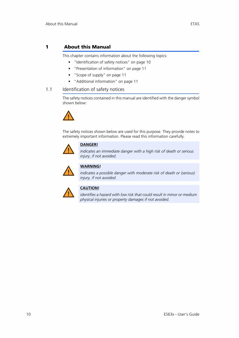
1.1 Identification of safety notices
The safety notices contained in this manual are identified with the danger symbolshown below:
The safety notices shown below are used for this purpose. They provide notes toextremely important information. Please read this information carefully.
DANGER!
indicates an immediate danger with a high risk of death or serious injury, if not avoided.
WARNING!
indicates a possible danger with moderate risk of death or (serious) injury, if not avoided.
CAUTION!
identifies a hazard with low risk that could result in minor or medium physical injuries or property damages if not avoided.
ES63x - User’s Guide
ETAS About this Manual
1.2 Presentation of information
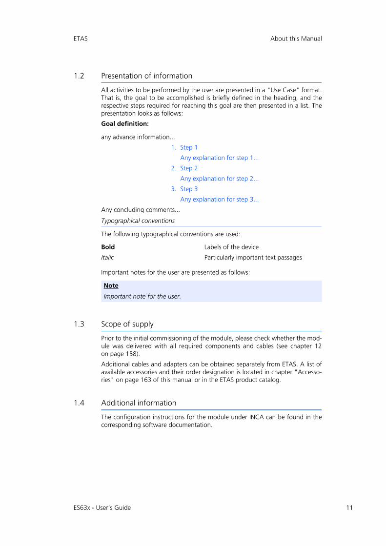
All activities to be performed by the user are presented in a "Use Case" format.That is, the goal to be accomplished is briefly defined in the heading, and therespective steps required for reaching this goal are then presented in a list. Thepresentation looks as follows:
Goal definition:
any advance information...
1. Step 1
Any explanation for step 1...
2. Step 2
Any explanation for step 2...
3. Step 3
Any explanation for step 3...
Any concluding comments...
Typographical conventions
The following typographical conventions are used:
Important notes for the user are presented as follows:
1.3 Scope of supply
Prior to the initial commissioning of the module, please check whether the mod-ule was delivered with all required components and cables (see chapter 12on page 158).
Additional cables and adapters can be obtained separately from ETAS. A list ofavailable accessories and their order designation is located in chapter "Accesso-ries" on page 163 of this manual or in the ETAS product catalog.
1.4 Additional information
The configuration instructions for the module under INCA can be found in thecorresponding software documentation.
Bold Labels of the device
Italic Particularly important text passages
Note
Important note for the user.
ES63x - User’s Guide 11
12
Basic Safety Notices ETAS
2 Basic Safety Notices
This chapter contains information about the following topics:
• "General Safety Information" on page 12
• "Requirements for Users and Duties for Operators" on page 12
• "Intended Use" on page 12
2.1 General Safety Information
Please observe the Product Safety Notices ("ETAS Safety Notice") and the follow-ing safety notices to avoid health issues or damage to the device.
ETAS GmbH does not assume any liability for damages resulting from improperhandling, unintended use or non-observance of the safety precautions.
2.2 Requirements for Users and Duties for Operators
The product may be assembled, operated and maintained only if you have thenecessary qualification and experience for this product. Improper use or use by auser without sufficient qualification can lead to damages or injuries to one'shealth or damages to property.The assembler of the system is responsible for the safety of any system incorper-ating the equipment.
General Safety at Work
The existing regulations for safety at work and accident prevention must be fol-lowed. All applicable regulations and statutes regarding operation must bestrictly followed when using this product.
2.3 Intended Use
Application Area of the Product
This product was developed and approved for applications in the automotivesector. The module is suitable for use in interiors, in the passenger cell or in thetrunk of vehicles. The module is not suitable for installation in the engine com-partment and similar environments. For use in other application areas, pleasecontact your ETAS contact partner.
Requirements for the Technical State of the Product
The product is designed in accordance with state-of-the-art technology and rec-ognized safety rules. The product may be operated only in a technically flawlesscondition and according to the intended purpose and with regard to safety anddangers as stated in the respective product documentation. If the product is notused according to its intended purpose, the protection of the product may beimpaired.
Note
Carefully read the documentation (Product Safety Advice and this User's Guide) that belongs to the product prior to the startup.
ES63x - User’s Guide
ETAS Basic Safety Notices
Requirements for Operation
• Use the product only according to the specifications in the corresponding User's Guide. With any deviating operation, the product safety is no lon-ger ensured.
• Observe the requirements on the ambient conditions.
• Do not use the product in a wet or damp environment.
• Do not use the product in potentially explosive atmospheres.
Electrical Safety and Power Supply
• Observe the regulations applicable at the operating location concerning electrical safety as well as the laws and regulations concerning work safety!
• Connect only current circuits with safety extra-low voltage in accordance with EN 61140 (degree of protection III) to the connections of the module.
• Ensure that the connection and setting values are being followed (see the information in the chapter "Technical data").
• Do not apply any voltages to the connections of the module that do not correspond to the specifications of the respective connection.
Power Supply
• The power supply for the product must be safely disconnected from the supply voltage. For example, use a car battery or a suitable lab power sup-ply.
• Use only lab power supplies with double protection to the supply network (with double insulation/reinforced insulation (DI/ RI)).
• The lab power supply must be approved for an operating altitude of 5000 m and for an ambient temperature of up to 70 °C.
• In regular operation of the modules as well as very long standby opera-tion, a discharge of the vehicle battery is possible.
Connection to the Power Supply
• The power cable must not be connected directly to the vehicle battery or lab power supply, but via a fuse of up to 20 A.
• Ensure that the connections of the lab power supply, the power supply at the module and the vehicle battery are easily accessible!
• Route the power cable in such a way that it is protected against abrasion, damages, deformation and kinking. Do not place any objects on the power cord!
ES63x - User’s Guide 13

14
Basic Safety Notices ETAS
Disconnecting from the Power Supply
The module does not have an operating voltage switch. The module can be de-energized as follows:
• Disconnecting the module from the lab power supply
– Separating device is the lab plug of the power cable or
– Separating device is the plug of the power cable at the connection of the module
• Disconnecting the module from the vehicle battery
– Separating device is the lab plug of the power cable or
– Separating device is the plug of the power cable at the connection of the module
• Disconnecting the vehicle battery.
Approved Cables
• Use exclusively ETAS cables at the connections of the module!
• Adhere to the maximum permissible cable lengths!
• Do not use any damaged cables! Cables may be repaired only by ETAS!
• Never apply force to insert a plug into a socket. Ensure that there is no contamination in and on the connection, that the plug fits the socket, and that you correctly aligned the plugs with the connection.
Requirements for the Location
• Position the module or the module stack on a smooth, level and solid underground.
• The module or the module stack must always be securely fastened.
Fixing the Modules on a Carrier System
• When selecting the carrier system, observe the static and dynamic forces that could be created by the module or the module stack on the carrier system.
Requirements on the Ventilation
• Keep the module away from heat sources and protect it against direct exposure to the sun.
• The free space above and behind the module must be selected so that sufficient air circulation is ensured.
DANGER!
Dangerous electrical voltage!Connect the power cable only with a suitable vehicle battery or with a suitable lab power supply! The connection to power outlets is not allowed!To prevent an inadvertent insertion in power outlets, ETAS recom-mends to equip the power cables with safety banana plugs in areas with power outlets.
ES63x - User’s Guide
ETAS Basic Safety Notices
Assembling (Interconnecting) the Modules
• Prior to assembling (interconnecting) or separating a module stack, the modules must be disconnected from the supply voltage or they have to be in the standby operating mode.
Transport
• Stack and connect the modules only at the location of the startup!
• Do not transport the modules at the cable of the module or any other cables.
Maintenance
The product is maintenance-free.
Repair
If an ETAS hardware product should require a repair, return the product to ETAS.
Cleaning the Module Housing
• Use a dry or lightly moistened, soft, lint-free cloth for cleaning the module housing.
• Do not user any sprays, solvents or abrasive cleaners which could damage the housing.
• Ensure that no moisture enters the housing. Never spray cleaning agents directly onto the module.
Ambient Conditions
The housing and the connectors of the module as well as the plug connectors ofthe cables meet the degree of protection IP40.
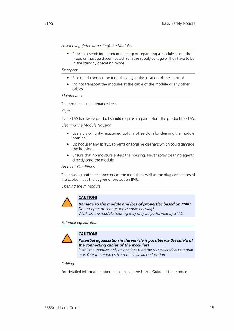
Opening the m´Module
Potential equalization
Cabling
For detailed information about cabling, see the User's Guide of the module.
CAUTION!
Damage to the module and loss of properties based on IP40!Do not open or change the module housing!Work on the module housing may only be performed by ETAS.
CAUTION!
Potential equalization in the vehicle is possible via the shield of the connecting cables of the modules!Install the modules only at locations with the same electrical potential or isolate the modules from the installation location.
ES63x - User’s Guide 15

16
Basic Safety Notices ETAS
Notices about Specific Components
During operation the lambda sensor at the module, a supply voltage is requiredfor the sensor heater. Since the sensor heater is not supplied with current by themodule, this supply voltage must be provided separately at the sensor cable.
CAUTION!
Risk of burns! The lambda sensor is very hot during operating and some time after operation.
CAUTION!
Damage of the lambda sensor when operated without sensor heater!The lambda sensor must be supplied with current at all times when it is being operated and as soon as it is exposed to the exhaust gases of a combustion process. The regulated heating voltage is provided at the sensor connection if the sensor cable is connected with a separate voltage supply and connected to the module and if the signal for switching on the heater is present at the sensor cable.
CAUTION!
Operate the lambda sensors only on modules with up to date firmware!Prior to the start-up, update the firmware of the module with the current service software HSP to avoid damage of the lambda sensor!
Note
Operate the lambda sensors only with the original sensor plugs to be able to determine valid measurement data.
Note
The Bosch lambda sensor LSU ADV-D must be calibrated with the lambda mod-ule prior to use.
ES63x - User’s Guide

ETAS Hardware Description
3 Hardware Description
This chapter contains information on the following topics:
• "Lambda Modules" on page 17
• "Housing" on page 20
• "Block Diagram" on page 24
• "Measurement Channel" on page 24
• "Sensor Identification (TEDS)" on page 26
• "Sensor Cable" on page 26
• "Data Transfer via Ethernet" on page 27
• "Data Transfer via SMB" on page 32
• "Power Supply" on page 32
3.1 Lambda Modules
The Lambda Modules ES630.1, ES631.1, ES635.1 and ES636.1 are part of thefamily of ES600 modules for use in the lab and in the vehicle. They are universalprecision lambda measuring instruments that, in connection with lambda sen-sors, enable emission measuring for SI, diesel and gas engines.
Fig. 3-1 ES636.1 Lambda Module
The lambda modules ES630.1/ES635.1 (one channel) and ES631.1/ES636.1 (twochannel) scan the pump current, and then determine the oxygen content in theexhaust gas, as well as the values and reciprocals of the variable lambda and theair-fuel ratio. The conversions can be based on distinctive application- specificcharacteristics which can be downloaded to the module.
The algorithm used by the ES63x modules for controlling the pump current canbe adapted to suit specific sensors.
The ES63x modules supply and control the sensor heater. To protect the lambdasensor, the sensor heater’s operation may be allowed to continue beyond thepoint at which the measuring units within the modules have been shut off. Sim-ilarly, the heater can be powered up independently of the measurement function
ES630.1 ES631.1 ES635.1 ES636.1
Measurement Channels 1 2 1 2
External Pressure Sensor Port - - 1 2
ES63x - User’s Guide 17

18
Hardware Description ETAS
by an external signal (typically “Engine On”). The lambda modules monitor boththe sensor temperature and internal resistance while supplying relevant outputdata.
Thanks to a TEDS code inside the sensor or wiring connection, the modules rec-ognize the sensor type, preventing improper sensor operation. The modulesautomatically detect sensor and wiring defects.
All ES63x modules are capable of measuring the atmospheric pressure by meansof an integrated sensor. To the modules ES635.1 and ES636.1, an external pres-sure sensor can be connected in addition. With this external sensor, pressurechanges within the exhaust or air system can be measured. Influences of atmo-spheric and exhaust pressure changes on the lambda measurement can auto-matically be compensated by the lambda modules. Independently of lambdameasuring, pressure signals are available for further analyses. As an example, onthe basis of an air pressure measurement, the height profile of a test drive can berecorded. By means of the external sensor, the pressure in the turbo charger canbe measured.
Using an Ethernet connection, the ES63x lambda modules can be directly linkedto a PC running suitable measuring software, or interfaced with miscellaneousETAS compact hardware devices.
All modules feature an RS-232 interface and support the SMB protocol. In theevent that an LA4 lambda meter in an existing measurement hardware configu-ration must be changed out, it can be easily replaced by an ES63x module.
3.1.1 Measure Values
The ES63x modules use fuel- and sensor-specific curves to calculate the oxygencontent, the lambda value and the air/fuel ratio, A/F. The lambda sensor isinstalled in the exhaust system. This makes it possible to determine the followingparameters:
• Lambda
• Air/fuel ratio, A/F
• Oxygen content O2
• Fuel/air ratio, F/A
• 1 / lambda
• Pump current of the lambda sensor Ip• Internal resistance of the lambda sensor Ri
• Heater voltage Uh
• Heater current Ih• Nernst voltage Unernst
• Pump voltage Upump
• Sensor temperature T
• Ambient pressure pamb
• External pressure pexh (ES635.1 and ES636.1)
• Filling level of reservoir Fr (only applicable to the LSU5.1)
• State/ operational state of the sensor Sta
ES63x - User’s Guide
ETAS Hardware Description
3.1.2 Features
• Display for configuring and displaying the measure values
• Configurable linearized analog output
• Automatic sensor type detection
• Automatic sensor error detection
• Automatic wiring error detection
• Sensor heating even when module powered off
• Simultaneous determination of different measure values with one lambda sensor
• External pressure measurement for automatic compensation of the pres-sure dependence of the lambda sensor pump current (ES635.1 and ES636.1)
• Communication with the PC via an XCP-based protocol that is compatible with the existing ETAS Ethernet topology. The concept fulfils the following requirements:
– High bandwidth to be able to acquire measure values with high reso-lution and high sampling rates,
– Low transfer times for applications in function development,
– Exact synchronization with other measurement systems possible,
– Simple application based on the Ethernet integration in INCA, no com-plicated setting of bus parameters,
– Simple to integrate in measurement and calibration tools manufac-tured by third-party suppliers due to the use of XCP as application pro-tocol.
• Communication with the PC via SMB
• Designed for use both in the development environment and as a stand-alone device.
• Module suitable for use in automotive applications; suitable for use in the development environment and in the vehicle on test drives:
– Not sensitive to acceleration or mechanical damage,
– Not sensitive to extreme environmental conditions (temperature, dampness, EMC) and
– Very low temperature coefficients contribute to the reduction in the number of measurement errors.
• Part of the ETAS Tool Suite
• Stand-alone operation with Daisy Chain Configuration Tool from ES6xx-_DRV_SW
For the complete technical data of the ES63x, refer to the chapter "TechnicalData" on page 98.
ES63x - User’s Guide 19
20
Hardware Description ETAS
3.2 Housing
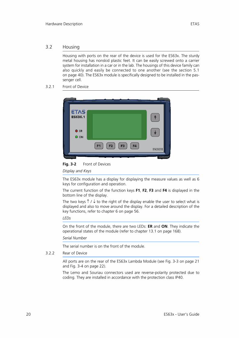
Housing with ports on the rear of the device is used for the ES63x. The sturdymetal housing has nonskid plastic feet. It can be easily screwed onto a carriersystem for installation in a car or in the lab. The housings of this device family canalso quickly and easily be connected to one another (see the section 5.1on page 40). The ES63x module is specifically designed to be installed in the pas-senger cell.
3.2.1 Front of Device
Fig. 3-2 Front of Devices
Display and Keys
The ES63x module has a display for displaying the measure values as well as 6keys for configuration and operation.
The current function of the function keys F1, F2, F3 and F4 is displayed in thebottom line of the display.
The two keys / to the right of the display enable the user to select what isdisplayed and also to move around the display. For a detailed description of thekey functions, refer to chapter 6 on page 56.
LEDs
On the front of the module, there are two LEDs: ER and ON. They indicate theoperational states of the module (refer to chapter 13.1 on page 168).
Serial Number
The serial number is on the front of the module.
3.2.2 Rear of Device
All ports are on the rear of the ES63x Lambda Module (see Fig. 3-3 on page 21and Fig. 3-4 on page 22).
The Lemo and Souriau connectors used are reverse-polarity protected due tocoding. They are installed in accordance with the protection class IP40.
ES63x - User’s Guide
ETAS Hardware Description
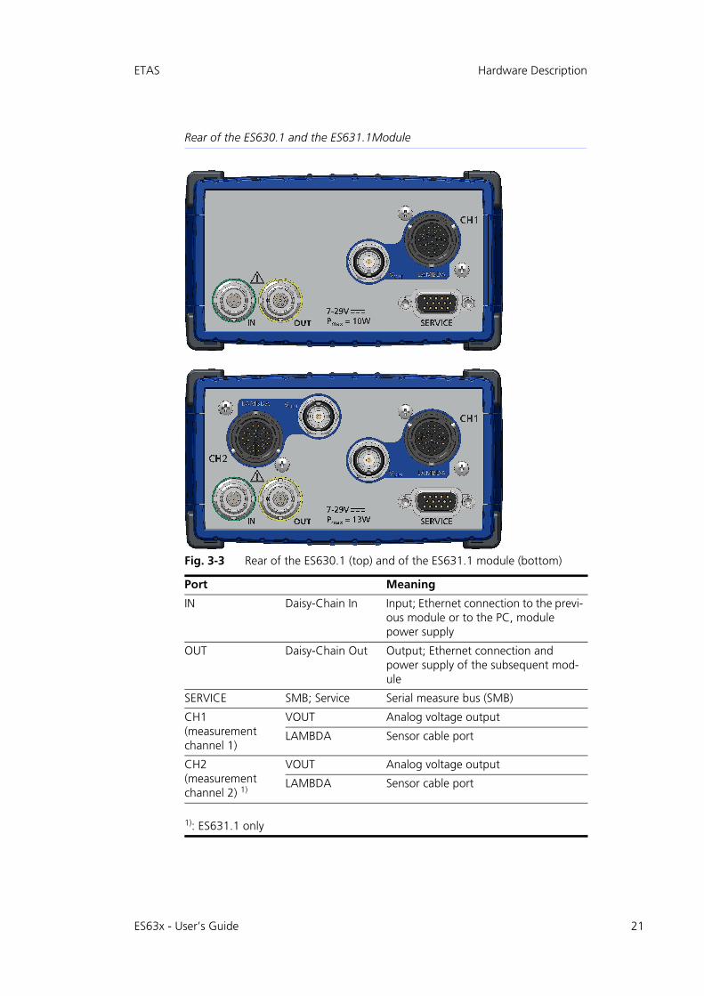
Rear of the ES630.1 and the ES631.1Module
Fig. 3-3 Rear of the ES630.1 (top) and of the ES631.1 module (bottom)
Port Meaning
IN Daisy-Chain In Input; Ethernet connection to the previ-ous module or to the PC, module power supply
OUT Daisy-Chain Out Output; Ethernet connection and power supply of the subsequent mod-ule
SERVICE SMB; Service Serial measure bus (SMB)
CH1(measurement channel 1)
VOUT Analog voltage output
LAMBDA Sensor cable port
CH2(measurement channel 2) 1)
VOUT Analog voltage output
LAMBDA Sensor cable port
1): ES631.1 only
ES63x - User’s Guide 21
22
Hardware Description ETAS
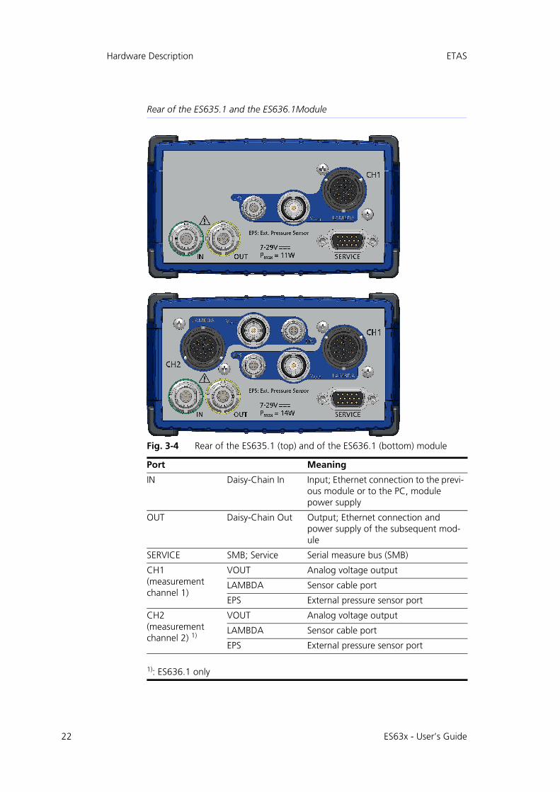
Rear of the ES635.1 and the ES636.1Module
Fig. 3-4 Rear of the ES635.1 (top) and of the ES636.1 (bottom) module
Port Meaning
IN Daisy-Chain In Input; Ethernet connection to the previ-ous module or to the PC, module power supply
OUT Daisy-Chain Out Output; Ethernet connection and power supply of the subsequent mod-ule
SERVICE SMB; Service Serial measure bus (SMB)
CH1(measurement channel 1)
VOUT Analog voltage output
LAMBDA Sensor cable port
EPS External pressure sensor port
CH2(measurement channel 2) 1)
VOUT Analog voltage output
LAMBDA Sensor cable port
EPS External pressure sensor port
1): ES636.1 only
ES63x - User’s Guide
ETAS Hardware Description
“LAMBDA” Port
A lambda sensor can be connected to the 22-pin Souriau jack using a sensorcable. Every measurement channel is assigned a 22-pin Souriau jack. A lambdasensor can be connected to each one with sensor cables.
The sensor cables (see section 11.5 on page 129) are equipped with a connectorfor the external supply voltage of the sensor heating as well as an input for con-trolling the heating. The sensor cables CBAL410.1, CBAL4105.1, CBAL451.1,CBAL4515.1, CBAL463.1, CBAL4635.1,CBAL468.1 and 4685.1 also have a portfor analog output signals.
“VOUT” Port
The analog output signal is made available at the BNC jack. The analog outputvoltage can be assigned to a measure value and its output parameters config-ured. Every measurement channel is assigned a BNC jack at which the analogoutput signal of the measurement channel is provided. The analog output volt-age can be assigned to a measure value and its output parameters configured.
Daisy Chain Ports (“IN”, “OUT”)
Every module has an explicit input socket (“IN”) as well as an explicit outputsocket (“OUT”). The modules are connected to each other in a chain structure.For this purpose, the output socket of one module and the input socket of thenext module are connected with a cable or a connector. This type of cabling isreferred to as daisy-chain topology.
The Ethernet data line and the supply voltage are routed through the daisy chainports of the module:
• “IN” (input) and
• “OUT” (output).
The PC, the ES600 network module, the ES910 or the Drive Recorder ES720 areconnected at the “IN” port (input). The “OUT” port (output) is connected withthe following ES63x or with a module of the ES400 line or remains free on thelast module of the chain.
“EPS” Port (ES635.1 and ES636.1)
An external pressure sensor can be connected to the 4-pin Lemo socket “EPS” tocompensate for the influence of exhaust gas pressure on the lambda sensorcurve during measurements in exhaust systems.
“SERVICE” Port
At the “Service” port, the ES63x module can be connected to an SMB bus usingan adapter and integrated in test setups like the Lambda Meter LA4.
Note
If ES63x modules are operated in an SMB bus (“SERVICE” port), each of these ES63x modules must be connected to the power supply at the “IN” port.
ES63x - User’s Guide 23
24
Hardware Description ETAS
3.3 Block Diagram
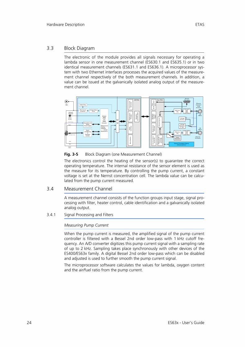
The electronic of the module provides all signals necessary for operating alambda sensor in one measurement channel (ES630.1 and ES635.1) or in twoidentical measurement channels (ES631.1 and ES636.1). A microprocessor sys-tem with two Ethernet interfaces processes the acquired values of the measure-ment channel respectively of the both measurement channels. In addition, avalue can be issued at the galvanically isolated analog output of the measure-ment channel.
Fig. 3-5 Block Diagram (one Measurement Channel)
The electronics control the heating of the sensor(s) to guarantee the correctoperating temperature. The internal resistance of the sensor element is used asthe measure for its temperature. By controlling the pump current, a constantvoltage is set at the Nernst concentration cell. The lambda value can be calcu-lated from the pump current measured.
3.4 Measurement Channel
A measurement channel consists of the function groups input stage, signal pro-cessing with filter, heater control, cable identification and a galvanically isolatedanalog output.
3.4.1 Signal Processing and Filters
Measuring Pump Current
When the pump current is measured, the amplified signal of the pump currentcontroller is filtered with a Bessel 2nd order low-pass with 1 kHz cutoff fre-quency. An A/D converter digitizes this pump current signal with a sampling rateof up to 2 kHz. Sampling takes place synchronously with other devices of theES400/ES63x family. A digital Bessel 2nd order low-pass which can be disabledand adjusted is used to further smooth the pump current signal.
The microprocessor software calculates the values for lambda, oxygen contentand the air/fuel ratio from the pump current.
Main FPGA
EthernetPhy
VoltageMonitor
100MBit /s
EthernetConnector
(Hostdirect ion)
Mea
sure
me
nt
Co
ntr
oll
erC
om
mu
nic
ati
on
Co
ntr
oll
er
Tim
eSy
nch
ron
izat
ion
Un
it
EthernetPhy
100MBit /s
EthernetConnector
Pro
toco
l E
ng
ine
FrameGenerator
VoltageRegulator
5...50V
Sub
syst
emC
on
tro
lle
rM
ast
er
Adjustable (U/I)Heater
Power Supply
Short circuitprotection
Output Diag.
TEDS
ActivateHeater
Ubatt
Heater
UN / VM / IP / Ri
DSP FPGA
He
ate
rC
on
tro
ller
Err
or
Mo
nit
or
Pu
mp
Cu
rre
nt
Co
ntr
oll
er
Mea
sure
men
tP
roce
sso
r
Dis
pla
y &
Use
rIn
terf
ace
Co
ntr
oll
er
Vacuum Fluorescent Display& Menu But tons
Multiple
A/Dand
D/AConverter
- Measurement- Heating- Operation Control- Maintenance
Analog OutputDriver
Sub
syst
emC
on
tro
ller
Slav
e
„ Service“Connector
BNC
SignalConditioning
&Operation
Control
Heater-Supply
Lemo(4-pol)
ExhaustPressure
ES63x - User’s Guide
ETAS Hardware Description
Measuring Internal Resistance
When the internal resistance is measured, the signal is filtered by a Bessel 2ndorder low-pass with a cutoff frequency of 50 Hz. The subsequent A/D converterdigitizes the signal with a sampling rate of up to 20 Hz. A digital Bessel 2nd orderlow-pass which can be disabled and adjusted is used to further smooth the signalthat feeds a digital controller that controls sensor heating.
Depending on the sensor temperature, the Ri measuring unit supplies a voltagewhich, once filtered and digitized, is used as the actual value for controlling theheating temperature of the sensor.
3.4.2 Pressure Compensation
The partial pressure of the oxygen influences the pump current measure signalprovided by lambda sensors. Changes in pressure of the gas mixture surroundingthe sensor in the exhaust duct therefore change the pump current measured andthus all calculated variables such as lambda, oxygen content and air/fuel ratio.
Compensation of the Ambient Pressure
The ES63x.1 has an internal sensor for measuring ambient pressure that can beused to compensate the lambda sensor signal or as a barometric altitude sensor.The ambient pressure determined can be output by the module.
Pressure Compensation in Open Exhaust Systems
The ambient pressure depends on the altitude above sea level in which thelambda sensor is used. If there is no (mechanical) obstruction for the exhaust gasin the exhaust system and the lambda sensor is mounted close to the end of theexhaust pipe, the exhaust gas pressure at the lambda sensor is about the sameas the ambient pressure. The lambda sensor signal is sufficiently exact. Apartfrom ambient pressure compensation, no further pressure compensation is nec-essary.
Pressure Compensation in Complex Exhaust Systems (ES635.1 and ES636.1)
If there are obstructions for the exhaust gas in the exhaust system, such as tur-bochargers, particle filters, catalytic converters or valves, the exhaust gas pres-sure inside the exhaust system can be much higher than the ambient pressure. Ifthe lambda sensor is mounted in this section of the exhaust system, the exhaustgas pressure influences the lambda sensor signal and is thus detrimental to mea-surement accuracy. Instead of the compensation of ambient pressure, the influ-ence of exhaust gas pressure on the pump current must be compensated.
To compensate for the dependence between exhaust gas pressure and the pumpcurrent of the lambda sensor, the pressure of the exhaust gas flow is measuredwith an additional pressure sensor mounted close to the lambda sensor in theexhaust system. The pressure sensor is connected to the exhaust system using acustomized adapter (a pipe/tube construction) for the purposes of thermal isola-tion.
Note
ETAS does not supply the components for thermal isolation of the pressure sensor.
ES63x - User’s Guide 25

26
Hardware Description ETAS
The ES63x uses the signal of the pressure sensor connected to the “EPS” port tocalculate a corrected pump current signal in accordance with the compensationcurves of the lambda sensor manufacturer.
This procedure of exhaust pressure compensation (EPC) of the ES63x completelycompensates for the influence of static and slow-changing exhaust gas pressureson the lambda measurement.
Changes of the exhaust gas pressure in static operation of the engine or on achange of operating point (acceleration, using the gas pedal) are compensated.The influence of pressure fluctuations on the lambda sensor, caused by the com-bustion process and the opening of the exhaust valves, cannot be compensatedwith this procedure.
3.4.3 Heater Control
To operate the sensor at a target temperature, the current sensor internal resis-tance is permanently compared to its desired value and the effective heating per-formance updated.
This control circuit can be operated independently of the digital part of the ES63xand can therefore guarantee an operational sensor even when the module isswitched off.
3.4.4 Analog Output "VOUT"
The ES635.1 also has a connector "VOUT" for analog output signals for eachmeasurement channel. The analog output of the ES635.1 is galvanically sepa-rated, protected against shorts and overload (see section 10.8.8 on page 109).
3.5 Sensor Identification (TEDS)
The connected sensor must be identified to coordinate the operating parametersof the ES63x with the connected sensor and rule out faulty operation.
3.5.1 Sensor Cable with Cable Identification (TEDS)
The ETAS sensor cables for the Bosch Lambda Sensors LSU 4.2, LSU 4.9and LSU5.2 as well as for the NTK Lambda Sensors ZFAS-D, ZFAS-U2 and ZFAS-U3 con-tain an active component (TEDS) for cable identification and thus the connectedlambda sensor.
3.5.2 Lambda Sensor with Sensor Identification (TEDS)
The Bosch Lambda Sensors LSU ADV-G (Code A7), LSU ADV-D (Code 1) andLSU 5.1 contain an active component (TEDS) in its cable for identifying the con-nected lambda sensor. For the sensors LSU ADV-D and LSU 5.1 the TEDS alsoholds the last calibration data.
3.6 Sensor Cable
The sensor cables are equipped with a connector for the heating voltage of thesensor as well as with a control line for the sensor heating. Sensor cables areavailable both with and without an analog output jack.
ES63x - User’s Guide
ETAS Hardware Description
3.7 Data Transfer via Ethernet
For data transfer, the ES63x and ES400 modules use a 100 Mbit/s Ethernet net-work connection in duplex operation. The data transfer can be adapted flexiblyto suit the test setup and the measurement task.
3.7.1 Communication Protocols
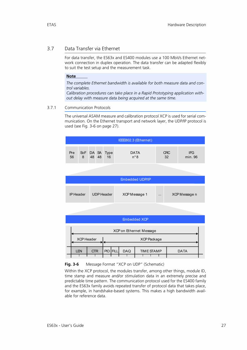
The universal ASAM measure and calibration protocol XCP is used for serial com-munication. On the Ethernet transport and network layer, the UDP/IP protocol isused (see Fig. 3-6 on page 27).
Fig. 3-6 Message Format “XCP on UDP” (Schematic)
Within the XCP protocol, the modules transfer, among other things, module ID,time stamp and measure and/or stimulation data in an extremely precise andpredictable time pattern. The communication protocol used for the ES400 familyand the ES63x family avoids repeated transfer of protocol data that takes place,for example, in handshake-based systems. This makes a high bandwidth avail-able for reference data.
Note
The complete Ethernet bandwidth is available for both measure data and con-trol variables. Calibration procedures can take place in a Rapid Prototyping application with-out delay with measure data being acquired at the same time.
SA48
UDP Header
IFGmin. 96
IP Header
DA48
Pre56
SoF8
CRC32
Type16
DATAn* 8
XCP Message 1 XCP Message n...
XCP on Ethernet Message
XCP Header XCP Package
DATATIME STAMPDAQFILLPIDCTRLEN
Embedded UDP/IP
Embedded XCP
IEEE802.3 (Ethernet )
ES63x - User’s Guide 27

28
Hardware Description ETAS
Using the UDP/IP standard for data transfer makes it possible to connect theES400 modules or the ES63x modules directly to a PC, a router or a switch. InXCP communication, the PC has the master function.
No real-time requirements are made. Data acquisition on a PC, which generallydoes not have to fulfill high real-time requirements, can thus be connecteddirectly to a module chain. With a real-time-capable master, such as, for exam-ple, a Rapid Prototyping system, lots of different kinds of I/O signal can beaccessed with extremely short cycle times.
3.7.2 Realization
Time Slice Procedure
The ES400 modules in the daisy chain transfer the data to the master using a100 MBit/s Ethernet connection time-controlled, i.e. without being prompted.The PC assumes the function of the master. In the network, the ES400 modulesrespond like a single Ethernet device with one MAC address.
All ES400 and ES63x modules have a generator which is only activated in the lastmodule of each chain after the test setup has been connected to the PC. Thefrequency of the generator or the period duration of the time slices generatedcan be set in the application program. It corresponds to the measuring frequencyof the measurement channel with the highest acquisition rate in the chain.
A binary counter linked to the generator periodically counts the time slices gen-erated (value range: 216 = 65536). The last module in the chain sends the rele-vant number of time slices in the IP header. The Ethernet frames are transferredfrom module to module within the chain.
Each module in the chain receives bandwidth to transfer its measure data infreely selectable time slices assigned within the period of the binary counter. Themodule uses the number of the time slice to determine whether it can insert anXCP message with its measure data into the current time slice.
The fastest module, which determines the period duration of the time slices gen-erated, transfers data in every time slice. An Ethernet frame then contains at leastone XCP-on-Ethernet data package. The length of the Ethernet frame trans-ferred inside a time slice increases with the number of modules which can inserttheir data into this time slice.
The numbering of the time slices ensures, for example, that two modules whichwork with half the sampling rate of the generator never attach their data to thesame Ethernet frame. One module uses only the odd frame numbers and theother only the even ones. This mechanism also ensures for certain that theassigned frames do not exceed the length of a time slice.
The measure data is automatically distributed to the frames so that the availablebandwidth is used perfectly.
The time slice procedure makes both measurements of fast signals and the acqui-sition of a large number of channels with a low sampling rate possible.
Note
The communication protocol used by the ES63x makes it possible for other suppliers to use the communication protocol for their own, non-ETAS applica-tions once the modules have been configured with the “Daisy Chain Configu-ration Tool from ES6xx_DRV_SW”.
ES63x - User’s Guide

ETAS Hardware Description
If a few fast signals and lots of slow ones are acquired in a chain, the slow signalscan be transferred in time multiplex procedure.
Clock Generator for Synchronizing Modules
The clock generator for the synchronization of the modules is either the firstmodule in an ES400 chain, the first module in an ES63x chain or the networkmodule ES600. In both cases, the measure data is synchronized with a toleranceof one microsecond. Using an ES600 network module, several ES400/ES63xchains can be synchronized with each other or with the modules of the ES600series. The ES400/ES63x and ES600 modules add the relevant time stamp to theEthernet data package for every measure value. The exact assignment in terms oftime of the measure data of the ES400/ES63x and ES600 modules used resultingfrom this makes precise analysis of the correlations of measure signals possible.
Synchronizing the ES63x and INCA Signal Processing
Data transfer does not require synchronization of the local timebases of theES400/ES63x modules. The time stamps are still synchronized by the ES400/ES63x system to be able to correlate measure data and sampling times of differ-ent modules in terms of time after data transfer. A precise time and drift synchro-nization takes place in the ES400/ES63x modules via a hardware connection.
No bandwidth is required for this, unlike time synchronization in acc. withIEEE1588 (Precision Time Protocol). The modules add the time stamp to theEthernet data package for every measure date.
The combination of time stamp synchronization, full duplex and time slice proce-dure results in a very high reference data rate of the ES400 measure modules.
Note
Due to data transfer by Ethernet, there are virtually no limitations in terms of the number of modules in a module chain even with fast sampling rates.
ES63x - User’s Guide 29

ES63x-
User’s G
uide30
ETAS
Hardw
are Description
3
00/ES63x modules with the same acquisition rates.
a PC
100 microseconds long. Modules 1, 2 and 3 acquiree 3 link their measure values to each time slice (see
C to the modules.
t [µs]
M3 M2 M1 R
thernet Frame 5
500
P/IP Header
erved for addit ionalmunicat ion
asured values of module n
.7.3 Examples
Example 1
Fig. 3-7 on page 30 shows an example of an application with three concatenated ES4The transfer scheme for this configuration is shown in Fig. 3-8 on page 30.
Fig. 3-7 Time-Multiplex Data Transfer Between an ES400/ES63x Module Chain and
Fig. 3-8 Transfer Scheme for Example 1 (Simplified, Not True to Scale)
In this example, the third module periodically generates 216 (65536) time slices each measure values with the same rate of 10 kHz each. Module 1, Module 2 and ModulFig. 3-8 on page 30).
Independently of this, control variables can be transferred at the same time from the P
Control variables
Measuredvalues M1
Rate: 10 kHz
Signal inject ion
Signal ext ract ion
FrameGenerator(inakt iv)
MODULE 1
Control variables
Measuredvalues M2
Rate: 10 kHz
Signal inject ion
FrameGenerator(inakt iv)
MODULE 2
Signal ext ract ion
Control variables
Measuredvalues M3
Rate: 10 kHz
Signal inject ion
Signal ext ract ion
FrameGenerator(10 kHz)
MODULE 3
Ethernet100 Mbit /s
PC
Ethernet Frame 1
M3 M2 M1H R M3 M2 M1H RM3 M2 M1H R
2000 100
Ethernet Frame 2Ethernet Frame 65536
Periode Frame Generator
M3 M2 M1H R
Ethernet Frame 3
M3 M2 M1H R
Ethernet Frame 4
H
E
300 400
H UD
RRescom
Mn Me
ES63x-
User’s G
uide31
Hardw
are Description
ETAS
n rates are linked to each other. The transfer scheme
a PC
t frames) each 100 microseconds long. The moduless its measure values to each Ethernet frame, module figure).
C to the modules.
t [µs]
M3 M2 M1 R
hernet Frame 5
500
/IP Header
rved for addit ionalmunicat ion
sured values of module n
Example 2
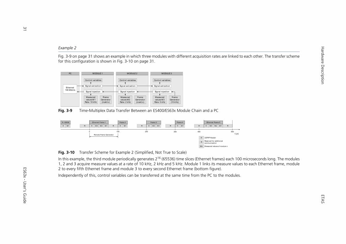
Fig. 3-9 on page 31 shows an example in which three modules with different acquisitiofor this configuration is shown in Fig. 3-10 on page 31.
Fig. 3-9 Time-Multiplex Data Transfer Between an ES400/ES63x Module Chain and
Fig. 3-10 Transfer Scheme for Example 2 (Simplified, Not True to Scale)
In this example, the third module periodically generates 216 (65536) time slices (Etherne1, 2 and 3 acquire measure values at a rate of 10 kHz, 2 kHz and 5 kHz. Module 1 link2 to every fifth Ethernet frame and module 3 to every second Ethernet frame (bottom
Independently of this, control variables can be transferred at the same time from the P
Control variables
Measuredvalues M1
Rate: 10 kHz
Signal inject ion
Signal ext ract ion
FrameGenerator(inakt iv)
MODULE 1
Control variables
Measuredvalues M2
Rate: 2 kHz
Signal inject ion
FrameGenerator(inakt iv)
MODULE 2
Signal ext ract ion
Control variables
Measuredvalues M3
Rate: 5 kHz
Signal inject ion
Signal ext ract ion
FrameGenerator(10 kHz)
MODULE 3
Ethernet100 Mbit /s
PC
Ethernet Frame 1
M1H R M1H RM3 M2 M1H R
2000 100
Frame 2Fr. 65536
Periode Frame Generator
M3 M1H R
Frame 3
M1H R
Frame 4
H
Et
300 400
H UDP
RResecom
Mn Mea

32
Hardware Description ETAS
3.8 Data Transfer via SMB
At the “SERVICE” port, the ES63x can be connected directly to an SMB bus usingthe serial interface (V24) and integrated in test setups like the Lambda MeterLA4.
Every measurement channel of a module is assigned its own SMB address (seesection 7.6.2 on page 74). The ES63x module thus requires two SMB addresses(one SMB address each for measurement channel CH1 and measurement chan-nel CH2) and can be addressed in the test setup like two LA4 modules.
SMB addresses must not be assigned twice over within the bus.
Up to 16 measuring modules can be connected to the serial interface of a PCusing the serial measuring bus. The transfer rate is 38,400 bauds using the for-mat 1 start bit, 8 data bits, 1 stop bit, and no parity.
Communication is always initiated by the PC. Every message contains theaddress of the measuring module and the command code. All the measuringmodules check this request, i.e. each module decodes it and compares theaddress part with the module address set in its memory. Only the moduleaddressed processes the message. The others ignore the message. Commandprocessing is defined specific to the module.
3.8.1 Request PC ES63x
Each message is 1 byte long. It consists of the address part for the moduleintended and a command part of 4 bits for the module-specific command code.
Every module address (0 to 15) must be unique.
3.8.2 Response ES63x PC
The information sent by the module contains no information on its format orstandardization. On request, only 1 byte is sent to the PC.
The PC must always request the HIGH byte first and then the associated LOWbyte. The LOW byte is only valid after the HIGH byte has been requested.
3.8.3 Code Table of SMB
When the PC is queried using defined codes, the ES63x sends information witha max. 1 byte (see section 10.8.4 on page 105).
3.9 Power Supply
The ES63x module and the lambda sensor are powered via separate power sup-ply connectors.
Note
The module and the lambda sensor must be connected to the supply voltage for measuring and for the firmware update of the ES63x.
Note
The ES63x must be physically disconnected from all supply voltages so the module is not supplied with power.
ES63x - User’s Guide

ETAS Hardware Description
3.9.1 Supply Voltage of the ES63x Modules
In every module, DC/DC converters guarantee the operation of the ES63x mod-ules (depending on the supply voltage and ambient temperature, see the section"Power Supply" on page 106).
3.9.2 Power Supply to ES63x Modules linked by Ethernet
In the simplest application case, the modules are linked directly to the daisy-chainports “IN” and “OUT”. They are connected to the supply voltage via the previousmodule all the way.
Additional Supply of the ES63x Modules via a Y Boost Cable
If the supply voltage (at the input) of a module is too low because of the currentconsumption of the previous modules, multiple feeding of the supply voltage canguarantee this and the following modules sufficient supply voltage in longermodule chains.
In this application case, you have to split the module chain. Swap the existingconnection cable between the two modules for a Y boost cable for additional,direct feeding of the supply voltage. The module chain is now closed again andthe power supply of the following modules guaranteed.
The special design of the Y boost cable avoids reverse feeding into the front partsof the module chain and thus arising potential differences.
When is it necessary to use a Y boost cable?
An exact calculation of the current consumption of a module chain is only possi-ble if numerous variables are known:
• supply voltage of the first module at the input
• minimum supply voltage at the last module of the chain
• number and type of the modules
• cable length
• cable type
• ambient temperature
The necessary minimum voltage for supplying power to the system must bedetermined individually for each test setup.
Example 1: For module chains which are equipped exclusively with ES63xmodules, ETAS recommends the use of Y boost cables if the length of the mod-ule chain is longer than 10 modules.
Note
Please contact ETAS to discuss your particular ES63x configurations.
ES63x - User’s Guide 33

34
Hardware Description ETAS
Example 2: With a minimum voltage of 7.7 V , no additional feeding is neces-sary with a Y cable if the module chain consists of the following modules:
• nine ES420 modules and
• four ES63x modules and
• one ES441 module.
3.9.3 Power Supply to ES63x Modules linked by SMB
If ES63x modules are operated in an SMB bus (“SERVICE” port), each of theseES63x modules must be connected to the power supply at the “IN” port.
3.9.4 Supply Voltage of the Lambda Sensor
The lambda sensor requires a supply voltage to operate the heating. When sev-eral ES63x modules are used, each lambda sensor must be powered separately.
Note
The examples apply at an ambient temperature of 70 °C.
Note
Depending on the operating mode, the sensor can continue to be heated regardless of whether power is supplied to the module (see section 4.4 on page 38).
ES63x - User’s Guide

ETAS Functional Description
4 Functional Description
This chapter contains information on the following topics:
• "Broadband Lambda Sensors" on page 35
• "Operating Modes of the Measurement System" on page 35
• "Measure Values" on page 36
• "Sensor Heating" on page 38
4.1 Broadband Lambda Sensors
The Bosch lambda sensor LSU 5.1 is a planar single-cell limiting current sensor,the Bosch lambda sensors LSU 4.2, LSU 4.7, LSU 4.9, LSU 5.2, LSU ADV, and theNTK lambda sensor ZFAS-U2and ZFAS-U3 are planar two-cell, limiting currentsensors.
Unlike other sensors, which are comparing the exhaust gas oxygen ratio to theambient air, LSU 5.1 compares it to an integrated oxygen reservoir. The single-cellsensor LSU 5.1 is used to measure in lean environment.
As the above-mentioned two-cell sensors consist of a combination of a Nernstconcentration cell (sensor cell) and a pump cell transporting oxygen ions, theycan carry out precise measurements not only in the stoichiometric point at = 1,but also in the lean and rich ranges.
With the exception of the LSU ADV-D, all sensors are calibrated individually at thefactory.
The operational state of the lambda sensor is characterized by the followingparameters:
• Ri (internal resistance of the lambda sensor)
• Ip (pump current of the lambda sensor)
4.2 Operating Modes of the Measurement System
The measurement system consisting of ES63x and lambda sensor can be in thefollowing operating modes:
• Operational state “Normal” or
• Operational state "Measurement channel disabled, sensor heating on”.
4.2.1 Operational State “Normal”
In the operational state “Normal”, the ES63x is operated alone or in connectionwith other modules of the ES400/ES63x family. The module must be suppliedwith operating voltage at the “IN” input in this operational state. The display isonly activated in the operational state “Normal”.
Note
The ES63x must be physically disconnected from all supply voltages so the module is not supplied with power.
Note
Measure values are only available in the operational state “Normal”.
ES63x - User’s Guide 35

36
Functional Description ETAS
4.2.2 Operational State "Measurement channel Disabled, Sensor Heating On”.
The measurement channel or channels of the module and the display are dis-abled, the digital components are activated. The lambda sensor is powered viathe connected cable and can continue to be heated if necessary (see section 4.4on page 38).
4.3 Measure Values
4.3.1 Overview
The measure values of the ES63x Lambda Module can be output at various inter-faces (individually for each measurement channel of the ES631.1/ ES636.1 mod-ule):
• in the display of the module,
• in the calibration software on the PC,
• as a message at the SMB “SERVICE” port,
• as an analog voltage value at the module’s “VOUT” analog output,
• as an analog voltage value when using sensor cables with an additional analog output (see section 11.5 on page 129).
Output of the Measure Values in/to
Measure Value Display and calibration software
Analogoutput "VOUT"
SMB"SERVICE"port
Lambda Yes Yes Yes
Air/fuel ratio, A/F Yes Yes Yes
Oxygen content O2 Yes Yes Yes
Fuel/air ratio, F/A Yes Yes No
1 / lambda Yes Yes No
Pump current of the lambda sensor Ip
Yes Yes Yes
Internal resistance of the lambda sensor Ri
Yes Yes Yes
Heater voltage Uh Yes Yes No
Heater current Ih Yes Yes No
Nernst voltage Unernst Yes Yes No
Pump voltage Upump Yes Yes No
Sensor temperature T Yes Yes No
Ambient pressure pamb Yes Yes No
External pressure pexh (ES635.1 and ES636.1 only)
Yes Yes No
Filling level of reservoir (LSU 5.1 only) Fr
Yes Yes No
State Sta Yes No No
ES63x - User’s Guide

ETAS Functional Description
4.3.2 Output in the Calibration Software or on the Display
All measure values are available simultaneously and can be configured in thecalibration software. The measure values of the internal pressure sensor (ambientpressure pamb) and the external pressure sensor (external pressure pexh) can beeither acquired or displayed.
4.3.3 Output at the Analog Output
Measure Values
All measure values the ES63x sends to the PC via XCP can be output as an analogvoltage value at the analog output of the module and when using sensor cableswith an additional analog output at the BNC jack of the sensor cable (see section11.5 on page 129).
The BNC jack VOUT of the measurement channel on the rear of the module andthe BNC jack of the sensor cable are connected in parallel.
In the calibration software or at the module, you can select one each of themeasure values for output at the analog output of the ES63x.
Output Voltage
Dimensional equations apply for the output voltage at the analog output of theES63x according to the measure value output (see section 10.8.8 on page 109).
In the operational state “Standby”, no output voltage is available at the analogoutput.
4.3.4 Output at the “SERVICE” Port
At the “SERVICE” port, the ES63x can be connected to an SMB bus using anadapter and integrated in test setups like the Lambda Meter LA4. The functionscope of the module is limited to the function scope of the LA4.
Note
In this operating mode of the module, the ambient pressure compensation can be activated, but the measured pressure values cannot be output. Measuring with an extesrnal pressure sensor is not possible.
ES63x - User’s Guide 37
38
Functional Description ETAS
4.4 Sensor Heating
The heating of the sensor can be powered on independently of the power supplyof the module as the heater control is supplied with power via the sensor cable.
4.4.1 Operating Modes
Depending on the measuring tasks and where the lambda sensor is installed, thesensor may have to be operated (heated) independently from the actual measur-ing. The following settings are available for this purpose in the calibration soft-ware:
• “External Signal”
The setting “External Signal” is selected if the lambda sensor of the ES63x is installed in the exhaust system of a vehicle and the sensor heating is to be operated independently of measuring by being controlled with an external signal (e.g. terminal 15).
• “On”
This setting is selected when no cooling of the sensor is required for a specific set of measurements as the delay between measurements would otherwise be too long.
This setting can, for example, avoid the lambda sensor cooling off in start-stop tests with the control of the heater control via terminal 15.
• “Off”
“Off” is selected when the sensor only has to be ready for use when the measurement system (sensor, ES63x and calibration software) is active. An example of an application for this setting is working on the test bench.
4.4.2 Heater Control
The heater control of the ES63x is adapted to the selected lambda sensor. Theheater curve ensures a short warm-up phase and minimum thermal load of thesensor. The curve controls the relative heating performance of the sensor untilthe working temperature of the sensor has been reached.
The state of the heater control (enabled/disabled) depends on the followingcomponents:
• the operational state of the ES63x (“On”, “Off”), determined by the sup-ply voltage at the “IN” port,
• a heater control parameter selected in the calibration software,
• an external voltage for heater control as well as
• the supply voltage range of the sensor.
Note
The operating modes of the sensor heating described below only apply when the module is connected to a power supply. The lambda sensor is always heated when the ES63x is “On”!
ES63x - User’s Guide
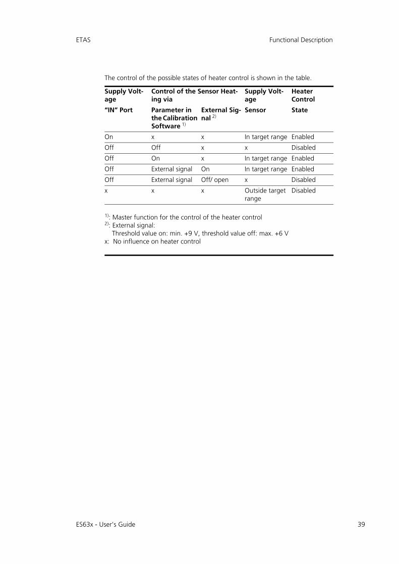
ETAS Functional Description
The control of the possible states of heater control is shown in the table.
Supply Volt-age
Control of the Sensor Heat-ing via
Supply Volt-age
HeaterControl
“IN” Port Parameter in the Calibration Software 1)
External Sig-nal 2)
Sensor State
On x x In target range Enabled
Off Off x x Disabled
Off On x In target range Enabled
Off External signal On In target range Enabled
Off External signal Off/ open x Disabled
x x x Outside target range
Disabled
1): Master function for the control of the heater control2): External signal:
Threshold value on: min. +9 V, threshold value off: max. +6 Vx: No influence on heater control
ES63x - User’s Guide 39
40
Getting Started ETAS
5 Getting Started
This chapter contains information on the following topics:
• "General Installation Recommendations" on page 40
• "Installing the Lambda Sensor" on page 43
• "Assembling the Pressure Sensor" on page 46
• "Applications" on page 48
• "Wiring" on page 51
• "Tool Integration" on page 54
• "Calibration" on page 55
5.1 General Installation Recommendations
5.1.1 Assembly Environment and Components for Attaching the Module
5.1.2 Potential Equalization in the Vehicle and Module Assembly
5.1.3 Fastening the Module onto a Carrier System
The ES63x module has a robust metal housing equipped with non-slip plasticfeet. The module can easily be screwed onto a support system for fastening inthe vehicle or lab. The screw threads for fastening the module are already in thehousing and easily accessible.
Fastening the housing of the Lambda Module:
1. Remove the plastic feet on the underside of the module. To do so, push the blunt screwdriver between bottom of housing and plastic foot. Pry off the plastic foot.
CAUTION!
The module can be damaged or destroyed.The modules are only admissible for assembly and operation on components or in locations which guarantee adherence to the tech-nical data of the modules during operation (see chapter 10 on page 98).
CAUTION!
Potential equalization possible in the vehicle via the shield of the Ethernet connecting cables of the modules!Only assemble the modules on components with the same electric potential or isolate the modules from the components.
ES63x - User’s Guide
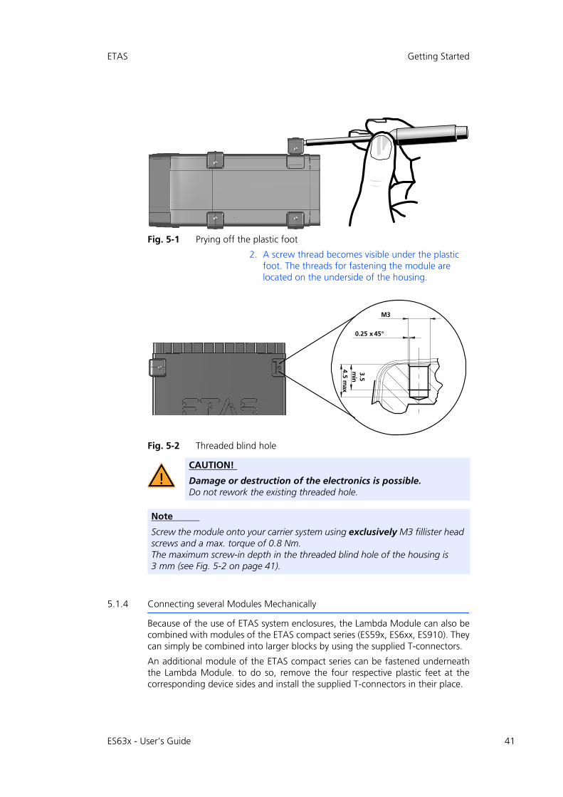
ETAS Getting Started
Fig. 5-1 Prying off the plastic foot
2. A screw thread becomes visible under the plastic foot. The threads for fastening the module are located on the underside of the housing.
Fig. 5-2 Threaded blind hole
5.1.4 Connecting several Modules Mechanically
Because of the use of ETAS system enclosures, the Lambda Module can also becombined with modules of the ETAS compact series (ES59x, ES6xx, ES910). Theycan simply be combined into larger blocks by using the supplied T-connectors.
An additional module of the ETAS compact series can be fastened underneaththe Lambda Module. to do so, remove the four respective plastic feet at thecorresponding device sides and install the supplied T-connectors in their place.
CAUTION!
Damage or destruction of the electronics is possible.Do not rework the existing threaded hole.
Note
Screw the module onto your carrier system using exclusively M3 fillister head screws and a max. torque of 0.8 Nm. The maximum screw-in depth in the threaded blind hole of the housing is 3 mm (see Fig. 5-2 on page 41).
jP
MKOR=ñ=QRø
PKR=ãáå
QKR=ã~ñ
ES63x - User’s Guide 41

42
Getting Started ETAS
Connecting several modules mechanically:
1. Remove the four plastic feet on the underside of the module to be able to fasten another module.
This exposes the installation openings for the T-con-nectors.
You can fasten an additional module underneath the Lambda Module.
2. Remove the four plastic feet on the corresponding side of the second module.
3. Turn the fasteners of the T-connectors transverse to the longitudinal axis of the connectors and click two connectors into the installation openings at one longitudinal side of the first module.
4. Click the second module into the two T-connectors.
Fig. 5-3 Connecting the Lambda Module with another module
5. Turn the fasteners of the T-connector by one-quar-ter turn. This locks the connection of the two mod-ules.
6. Click the two additional T-connectors into the installation openings on the opposite longitudinal side of the device and also lock those connectors.
7. If you want to stack additional modules and fasten them on top of each other, repeat the process with the next module.
ES63x - User’s Guide

ETAS Getting Started
5.2 Installing the Lambda Sensor
The following general guidelines apply when installing the LSU lambda sensor:
• Make sure that you install the sensor in exhaust pipes at a point at which the exhaust gas composition is representative and remains within the pre-scribed temperature limits.
The following maximum values are valid for the lambda sensors:
Cold exhaust gas at a high flow velocity can lead to the operating tem-perature of the sensor cell varying, depending on the operating voltage. This may result in measurement errors.
Hot exhaust gas at temperatures above the controlled ceramic tempera-ture may cause the operating temperature of the sensor cell to rise. This also may result in measurement errors.
• The active sensor ceramic is heated up quickly by the internal heater. The place of installation should be selected to ensure that the amount of con-densate penetrating from the exhaust gas system is minimal in order to avoid ceramic breakages.
The point of installation and position of the sensor should fulfill the fol-lowing requirements:
– Install the sensor as near the engine as possible. Maintain the mini-mum distance from the combustion chamber of 15 cm.
Note
For more details on the Bosch lambda sensors, consult
• "Bosch: Technical Customer Information on the LSU 4.7 / LSU 4.2“ (Y 258 K01 005-000e)
• "Bosch: Technical Customer Information on the LSU 4.9“ (Y 258 K01 008-000)
• "Bosch: Technical Customer Information on the LSU ADV-G“ (Y 258 K01 024-000)
• "Bosch: Technical Customer Information on the LSU 5.1“ (Y 258 K01 047)
• "Bosch: Technical Customer Information on the LSU 5.2"(Y 258 K01 068e)
Sensor Max. Gas Temperature Max. Temperature at the hexagonal screw
LSU 4.2 850 °C 570 °C
LSU 4.7 850 °C 570 °C
LSU 4.9 930 °C 570 °C
LSU ADV-D 930 °C 650 °C
LSU ADV-G 930 °C 650 °C
LSU 5.1 930 °C 650 °C
LSU 5.2 980 °C 650 °C
ES63x - User’s Guide 43

44
Getting Started ETAS
– Ensure rapid warm-up of the exhaust pipes just upstream of the sensor installation point.
– As far as possible, ensure the exhaust pipes are on a downward stretch to avoid the accumulation of condensate upstream of the sensor installation point (no recesses, projections, cutting edges).
• The angle of installation should be inclined at least 10° to the horizontal (tip of the sensor pointing downwards).
Fig. 5-4 Angle of Installation
This prevents condensate or fuel from accumulating between the sensor housing and the sensor ceramic during the cold-start phase.
• Install using special grease on screw thread (e.g. Bosch lambda sensor assembly paste, item number 1 987 123 020).
• Tightening torque: 50 Nm to 60 Nm, the material and strength of the thread have to be chosen accordingly.
• Avoid inadmissible heating of the sensor cable gland, particularly after the engine has been switched off.
• Do not use any cleaning or greasy liquids or vaporizing substances on the sensor connection.
To install the lambda sensor
1. Choose a position on the exhaust pipe for the lambda sensor which is at least 15 cm from the combustion chamber. Otherwise the sensor could suffer heat damage.
2. Before the sensor is installed, weld a threaded boss in the exhaust manifold.
Note
When installing the lambda sensor, please observe the installation guidelines in section 5.2 on page 43.
ES63x - User’s Guide
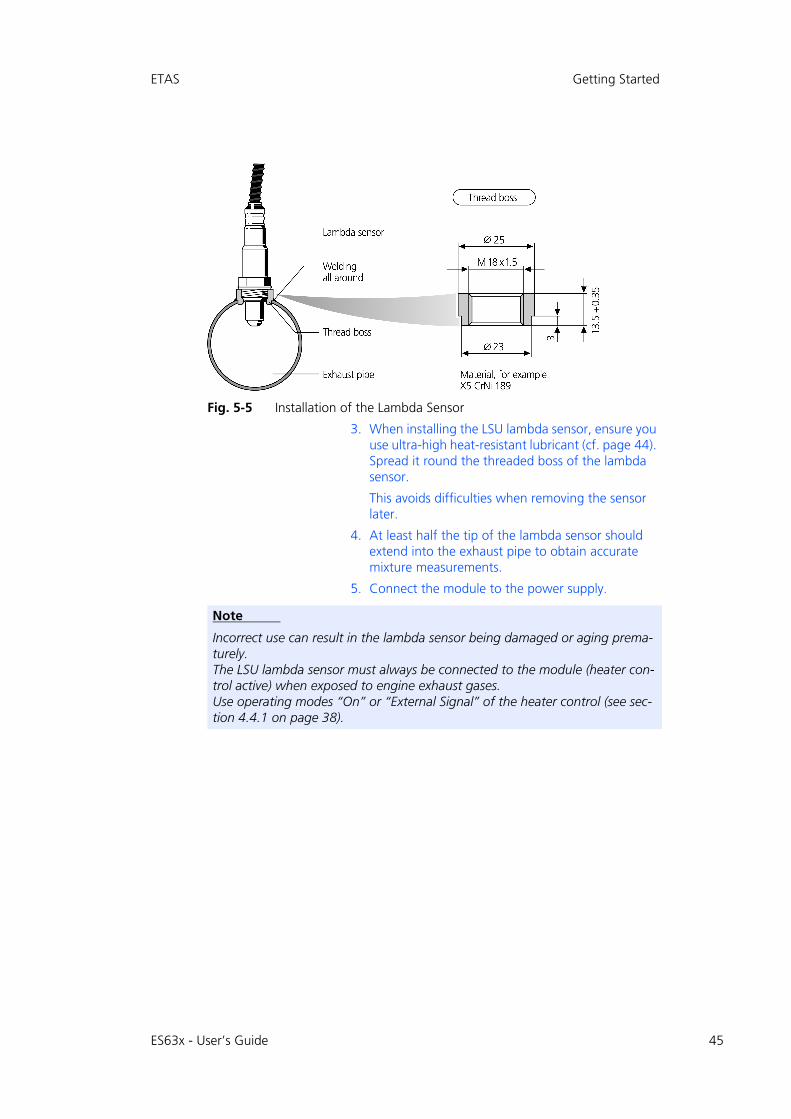
ETAS Getting Started
Fig. 5-5 Installation of the Lambda Sensor
3. When installing the LSU lambda sensor, ensure you use ultra-high heat-resistant lubricant (cf. page 44). Spread it round the threaded boss of the lambda sensor.
This avoids difficulties when removing the sensor later.
4. At least half the tip of the lambda sensor should extend into the exhaust pipe to obtain accurate mixture measurements.
5. Connect the module to the power supply.
Note
Incorrect use can result in the lambda sensor being damaged or aging prema-turely.The LSU lambda sensor must always be connected to the module (heater con-trol active) when exposed to engine exhaust gases. Use operating modes “On” or “External Signal” of the heater control (see sec-tion 4.4.1 on page 38).
ES63x - User’s Guide 45
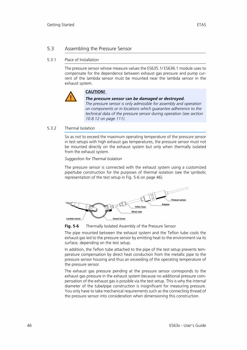
46
Getting Started ETAS
5.3 Assembling the Pressure Sensor
5.3.1 Place of Installation
The pressure sensor whose measure values the ES635.1/ ES636.1 module uses tocompensate for the dependence between exhaust gas pressure and pump cur-rent of the lambda sensor must be mounted near the lambda sensor in theexhaust system.
5.3.2 Thermal Isolation
So as not to exceed the maximum operating temperature of the pressure sensorin test setups with high exhaust gas temperatures, the pressure sensor must notbe mounted directly on the exhaust system but only when thermally isolatedfrom the exhaust system.
Suggestion for Thermal Isolation
The pressure sensor is connected with the exhaust system using a customizedpipe/tube construction for the purposes of thermal isolation (see the symbolicrepresentation of the test setup in Fig. 5-6 on page 46).
Fig. 5-6 Thermally Isolated Assembly of the Pressure Sensor
The pipe mounted between the exhaust system and the Teflon tube cools theexhaust gas led to the pressure sensor by emitting heat to the environment via itssurface, depending on the test setup.
In addition, the Teflon tube attached to the pipe of the test setup prevents tem-perature compensation by direct heat conduction from the metallic pipe to thepressure sensor housing and thus an exceeding of the operating temperature ofthe pressure sensor.
The exhaust gas pressure pending at the pressure sensor corresponds to theexhaust gas pressure in the exhaust system because no additional pressure com-pensation of the exhaust gas is possible via the test setup. This is why the internaldiameter of the tube/pipe construction is insignificant for measuring pressure.You only have to take mechanical requirements such as the connecting thread ofthe pressure sensor into consideration when dimensioning this construction.
CAUTION!
The pressure sensor can be damaged or destroyed.The pressure sensor is only admissible for assembly and operation on components or in locations which guarantee adherence to the technical data of the pressure sensor during operation (see section 10.8.12 on page 111).
bñ~ìëí=ÑìãÉëi~ãÄÇ~=ëÉåëçê
mêÉëëìêÉ=ëÉåëçê
jÉí~ä=íìÄÉ
^Ç~éíÉêqÉÑäçå=ÜçëÉ
ES63x - User’s Guide
ETAS Getting Started
Components for the Test Setup
The components necessary for the test setup for connecting the pressure sensorwith the exhaust system must be designed, and the parts selected and orderedby the customer. They are not part of the delivery scope or accessories of themodule and are not supplied by ETAS.
Suggestion for Components
The SS-8M0-7-4 tube fitting and the SS-8M5-6M tubing insert from the com-pany Swagelok can be used to make a suitable test setup. These act as a con-necting piece between the thread of the pressure sensor and the pipe/tubeconstruction attached to the exhaust duct.
5.3.3 Connecting with the Module
The pressure sensor has a permanent cable with a Lemo connector for the con-nection with the ES635.1/ ES636.1 module’s “EPS” port. In the case of largerdistances between the pressure sensor and the module, the pressure sensorcable can be extended using the CBAX100 cable.
Note
ETAS does not supply the components for thermal isolation of the pressure sensor.
ES63x - User’s Guide 47

48
Getting Started ETAS
5.4 Applications
5.4.1 ES63x Modules with ES4xx/ES600/ES720/ES910 and INCA
With INCA, signals can be acquired from the vehicle bus and ECUs calibratedparallel to the acquisition of sensor measure data.
In addition to the laptop, the drive recorder ES720 or the Rapid Prototyping Mod-ule ES910 can be used to read the ES400 modules data. The ES400 modules areinstalled in the vehicle or on the test stand.
ES63x Modules with ES600 Measurement Modules and INCA
Fig. 5-7 Application with ES63x Modules, ES600 Measurement Modules and INCA
Parallel to one or several ES400 chains, you can use the network module ES600to connect further ETAS modules to INCA. With the network module ES600, theES400 modules can be synchronized in terms of time with measure modules ofthe ES600 series based on the same mechanism.
ES63x
ES63x - User’s Guide
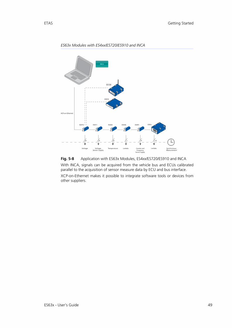
ETAS Getting Started
ES63x Modules with ES4xx/ES720/ES910 and INCA
Fig. 5-8 Application with ES63x Modules, ES4xx/ES720/ES910 and INCA
With INCA, signals can be acquired from the vehicle bus and ECUs calibratedparallel to the acquisition of sensor measure data by ECU and bus interface.
XCP-on-Ethernet makes it possible to integrate software tools or devices fromother suppliers.
ES63x
ES63x - User’s Guide 49

50
Getting Started ETAS
5.4.2 ES63x Modules with ES4xx/ES720/ES910 and INTECRIO
Fig. 5-9 Application with ES63x Modules, ES4xx/ES720/ES910 and INTECRIO
You can use the ES910 module to connect one ES400 chain to INTECRIO. Fig. 5-9on page 50 shows an example of operating one ES400 module chain with theES910 module. As an alternative to the ES910, the drive recorder ES720 can beused to acquire ES400 measure data.
ES63x
ES63x - User’s Guide
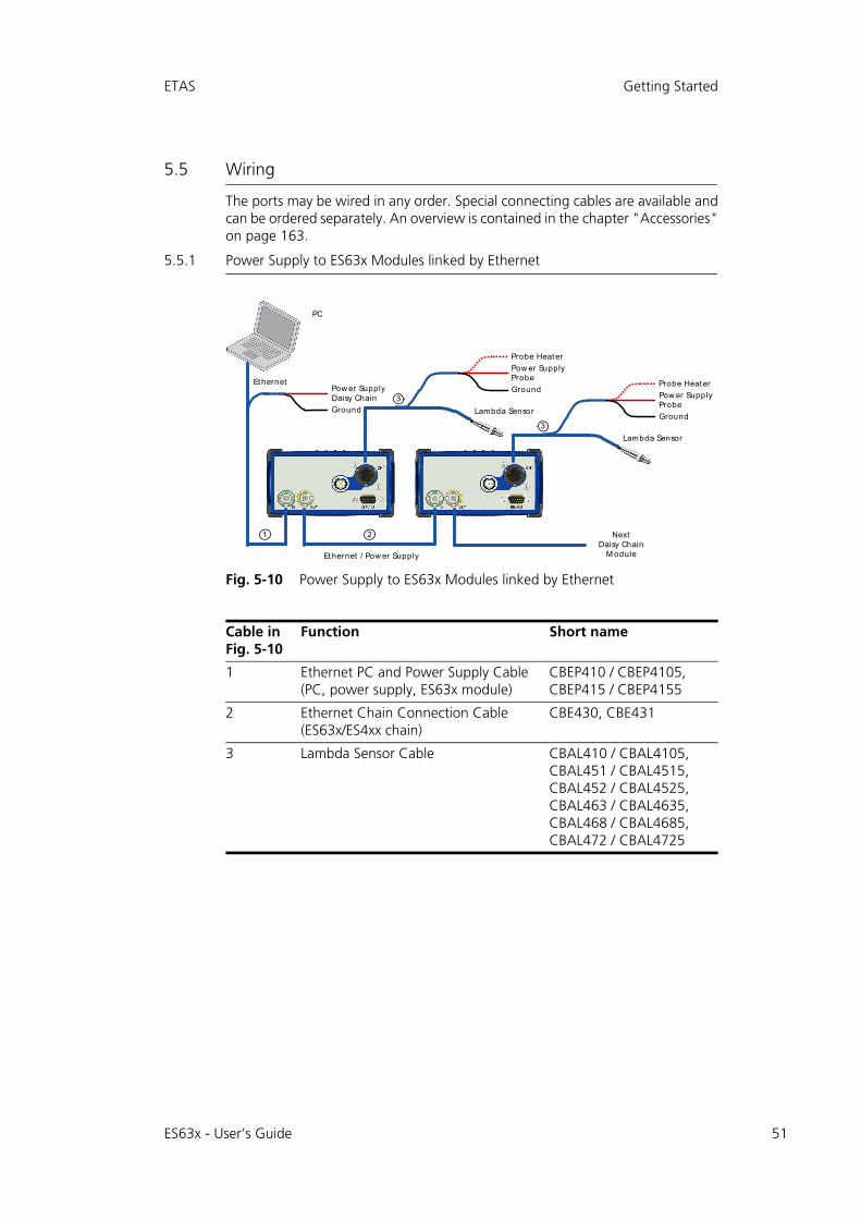
ETAS Getting Started
5.5 Wiring
The ports may be wired in any order. Special connecting cables are available andcan be ordered separately. An overview is contained in the chapter "Accessories"on page 163.
5.5.1 Power Supply to ES63x Modules linked by Ethernet
Fig. 5-10 Power Supply to ES63x Modules linked by Ethernet
Cable in Fig. 5-10
Function Short name
1 Ethernet PC and Power Supply Cable (PC, power supply, ES63x module)
CBEP410 / CBEP4105, CBEP415 / CBEP4155
2 Ethernet Chain Connection Cable (ES63x/ES4xx chain)
CBE430, CBE431
3 Lambda Sensor Cable CBAL410 / CBAL4105,CBAL451 / CBAL4515, CBAL452 / CBAL4525,CBAL463 / CBAL4635,CBAL468 / CBAL4685,CBAL472 / CBAL4725
PC
Ground
Pow er SupplyDaisy Chain
Lambda Sensor
Ground
Probe Heater
Pow er SupplyProbe
Lambda Sensor
Ground
Probe Heater
Pow er SupplyProbeEthernet
Ethernet / Pow er Supply
1 2
3
3
NextDaisy Chain
M odule
ES63x - User’s Guide 51
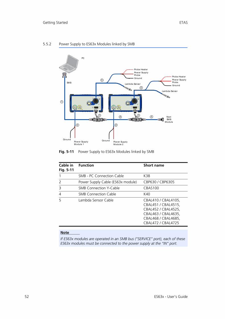
52
Getting Started ETAS
5.5.2 Power Supply to ES63x Modules linked by SMB
Fig. 5-11 Power Supply to ES63x Modules linked by SMB
Cable in Fig. 5-11
Function Short name
1 SMB - PC Connection Cable K38
2 Power Supply Cable (ES63x module) CBP630 / CBP6305
3 SMB Connection Y-Cable CBAS100
4 SMB Connection Cable K40
5 Lambda Sensor Cable CBAL410 / CBAL4105,CBAL451 / CBAL4515, CBAL452 / CBAL4525,CBAL463 / CBAL4635,CBAL468 / CBAL4685,CBAL472 / CBAL4725
Note
If ES63x modules are operated in an SMB bus (“SERVICE” port), each of these ES63x modules must be connected to the power supply at the “IN” port.
PC
Lambda Sensor
Ground
Probe Heater
Pow er SupplyProbe
Lambda Sensor
Ground
Probe Heater
Pow er SupplyProbe
GroundPow er SupplyM odule 1
GroundPow er SupplyM odule 2
NextSM B
M odule
SM B
1
2
34
2
34
5
5
ES63x - User’s Guide
ETAS Getting Started
5.5.3 Daisy Chain Ports (“IN”, “OUT”)
Wiring goes from the first module towards the end of the module chain.
To wire the first module with the following module
1. Connect an Ethernet cable to the “OUT” port of the first module.
2. Connect the Ethernet cable to the “IN” port of the next module.
3. Continue to wire or connect further modules as described above.
To wire the first module with the PC and the power supply
1. Connect the combined Ethernet and power supply cable to the “IN” port of the ES63x.
2. Connect the RJ-45 connector to the free Ethernet interface port of your PC.
3. Connect the supply voltage connector of the com-bined Ethernet and power supply cable to the desired power supply.
Note the color coding of the connectors.
To wire the module chain with additional current feeding
1. End the module chain after the last module whose power supply is still guaranteed in the entire opera-tional range.
2. Connect the combined Ethernet and power supply cable to the “OUT” port of the last ES63x module of the chain towards the PC.
3. Connect the combined Ethernet and power supply cable to the “IN” port of the ES63x of the next module towards the end of the chain.
4. Connect the supply voltage connector of the com-bined Ethernet and power supply cable to the desired power supply.
Note the color coding of the connectors.
ES63x - User’s Guide 53
54
Getting Started ETAS
5.5.4 “LAMBDA” Port
You can use different cables to connect the lambda sensors to the module.
To wire the ES63x with the sensor
1. If there is a protective cap at the “Sensor” port, remove it.
2. Connect the sensor cable to the “Sensor” port of the ES63x.
3. Connect the sensor to the sensor plug of the sensor cable.
To wire the control of the heater control
1. Pull the cable end out of the shrinkage tube of the sensor cable.
2. Connect the end of the cable to a suitable signal (e.g. terminal 15).
To wire the analog output of the ES63x (only special sensor cables)
1. Connect the BNC jack of the sensor cable to a data acquisition system, e.g. the analog input of the test stand.
To wire the sensor with the supply voltage
1. Connect the supply voltage connector of the sensor cable to a suitable power supply for the sensor.
Note the color coding of the connectors.
5.5.5 “VOUT” Port
To wire the “Analog” port of the ES63x
1. Connect the “VOUT” port of the ES63x (BNC jack) to a data acquisition system, e.g. the analog input of the test stand.
5.6 Tool Integration
The ES63x modules can be selected and configured in the calibration softwareand support the open protocol XCP-on-Ethernet. This enables easy integration ofthe modules into other measure software.
The measure system can be connected directly to the PC’s Ethernet port. Noadditional devices or interface converters are necessary.
Note
Refer to the detailed information on the sensor cables in section 11.5 on page 129.
ES63x - User’s Guide
ETAS Getting Started
5.7 Configuration
5.7.1 Configuring the Lambda Module
The configuration of the Lambda Module is performed via the GUI of the calibra-tion software or directly on the module. The configuration of the measurementchannel is saved either in the calibration software or in the individual ES400/ES63x modules. In the first case, you can prepare settings for specific measuretasks, e.g. in the lab. The second case is of interest to users who share a testcarrier with a corresponding ES400/ES63x test setup. In this way, several userscan call up the saved configuration directly from the modules.
5.7.2 Configuring the Lambda Sensor
The ES63x and the lambda sensors supported are designed to be operatedtogether.
5.7.3 Calibrating the Lambda Sensor LSU ADV-D
The calibration values for the lambda sensors LSU 5.1 and LSU ADV are stored inTEDS. The TEDS is mounted in the plug of the sensor.
5.8 Calibration
A calibration service is available for your Lambda Module. To ensure reliable accu-racy of the measurements, you should calibrate the ES63x once a year.
Information on the last calibration is stored in the device and in TEDS for LSUADV-D and LSU 5.1.
Please contact your local ETAS representative for information on the calibrationservice. You can find the contact information in the chapter "ETAS ContactAddresses" on page 197. For information on ordering the calibration service,refer to the chapter "Accessories" on page 163.
Note
If necessary, Lambda Module can be configured directly at the module without using calibration software (see chapter 6 on page 56).
CAUTION!
Operate the lambda sensors only on modules with up to date firmware!Prior to the start-up, update the firmware of the module with the current service software HSP to avoid damage of the lambda sensor!
Note
The Bosch lambda sensor LSU ADV-D must be calibrated with the lambda mod-ule prior to use.
ES63x - User’s Guide 55
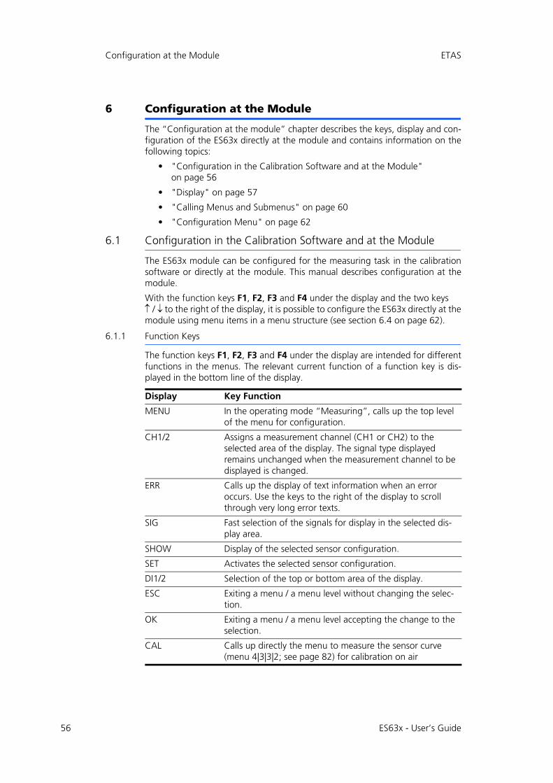
56
Configuration at the Module ETAS
6 Configuration at the Module
The “Configuration at the module” chapter describes the keys, display and con-figuration of the ES63x directly at the module and contains information on thefollowing topics:
• "Configuration in the Calibration Software and at the Module" on page 56
• "Display" on page 57
• "Calling Menus and Submenus" on page 60
• "Configuration Menu" on page 62
6.1 Configuration in the Calibration Software and at the Module
The ES63x module can be configured for the measuring task in the calibrationsoftware or directly at the module. This manual describes configuration at themodule.
With the function keys F1, F2, F3 and F4 under the display and the two keys/ to the right of the display, it is possible to configure the ES63x directly at themodule using menu items in a menu structure (see section 6.4 on page 62).
6.1.1 Function Keys
The function keys F1, F2, F3 and F4 under the display are intended for differentfunctions in the menus. The relevant current function of a function key is dis-played in the bottom line of the display.
Display Key Function
MENU In the operating mode “Measuring”, calls up the top level of the menu for configuration.
CH1/2 Assigns a measurement channel (CH1 or CH2) to the selected area of the display. The signal type displayed remains unchanged when the measurement channel to be displayed is changed.
ERR Calls up the display of text information when an error occurs. Use the keys to the right of the display to scroll through very long error texts.
SIG Fast selection of the signals for display in the selected dis-play area.
SHOW Display of the selected sensor configuration.
SET Activates the selected sensor configuration.
DI1/2 Selection of the top or bottom area of the display.
ESC Exiting a menu / a menu level without changing the selec-tion.
OK Exiting a menu / a menu level accepting the change to the selection.
CAL Calls up directly the menu to measure the sensor curve (menu 4|3|3|2; see page 82) for calibration on air
ES63x - User’s Guide
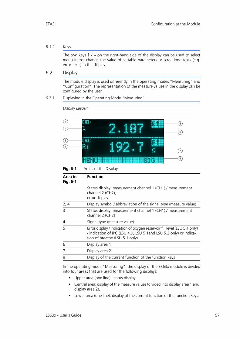
ETAS Configuration at the Module
6.1.2 Keys
The two keys / on the right-hand side of the display can be used to selectmenu items, change the value of settable parameters or scroll long texts (e.g.error texts) in the display.
6.2 Display
The module display is used differently in the operating modes “Measuring” and“Configuration”. The representation of the measure values in the display can beconfigured by the user.
6.2.1 Displaying in the Operating Mode “Measuring”
Display Layout
Fig. 6-1 Areas of the Display
In the operating mode “Measuring”, the display of the ES63x module is dividedinto four areas that are used for the following displays:
• Upper area (one line): status display
• Central area: display of the measure values (divided into display area 1 and display area 2),
• Lower area (one line): display of the current function of the function keys.
Area in Fig. 6-1
Function
1 Status display: measurement channel 1 (CH1) / measurement channel 2 (CH2),error display
2, 4 Display symbol / abbreviation of the signal type (measure value)
3 Status display: measurement channel 1 (CH1) / measurement channel 2 (CH2)
4 Signal type (measure value)
5 Error display / indication of oxygen reservoir fill level (LSU 5.1 only) / indication of IPC (LSU 4.9, LSU 5.1and LSU 5.2 only) or indica-tion of breathe (LSU 5.1 only)
6 Display area 1
7 Display area 2
8 Display of the current function of the function keys
5
6
7
8
1
2
3
4
ES63x - User’s Guide 57
58
Configuration at the Module ETAS
Representation of the Measure Values in the Display
The two central areas for displaying the measure values are identical in terms offunction. The measure values are displayed as follows in the upper and lowerareas of the display:
• Symbol / abbreviation of the signal type
• Measure value
• Unit of the measure value (if available).
In addition to the measure value, the measurement channels are also labeled inthe upper and lower areas of the ES631.1/ ES636.1 display:
• CH1: assignment of the display to measurement channel 1
• CH2: assignment of the display to measurement channel 2.
Adjusting the Display of Information in the Display
In the operating mode “Measuring”, a total of two measure values or signaltypes can be displayed simultaneously in the two display halves. The user canconfigure the display of measure values or signal types and assign the differentdisplays to the two display halves. In the upper and lower area of the display, youcan choose to display:
• Measure values of different signal types of the measurement channel
• Measure values of identical signal types of the measurement channel
Using the ES631.1/ ES636.1 module you can additionally choose to display:
• Measure values of different signal types of different measurement chan-nels
• Measure values of identical signal types of different measurement chan-nels
The display of the measure values can be hidden in one display half or bothdisplay halves. The division of the display into the areas described and the assign-ment to the signal types and measurement channels remains.
Displaying Measure Errors
Any errors that occur are displayed flashing in the top right corner in the upperor lower area of the display.
If, in modules with two measurement channels, two different signals of a mea-surement channel are assigned to the upper and lower areas of the display, onlyerrors of the channel shown are displayed. Errors of the hidden second measure-ment channel are not shown.
Other information can be displayed in the top right corner in the upper or lowerarea of the display:
• Ri : Ri too low
• Ri : Ri too high
• error
• fill level of oxygen reservoir (LSU 5.1 only)
• IPC (LSU 4.9, LSU 5.1 and LSU 5.2 only) or
ES63x - User’s Guide
ETAS Configuration at the Module
• breathe (LSU 5.1 only)
Selecting the Display Area
During measurement, the upper or lower display area can be selected using the/ keys to show a signal type in this display area.
Selecting the Displayed Signal Type During Measuring
Once the upper or lower display area has been selected, the signal type shown inthe display can be changed during measuring.
Parameters and settings cannot be changed during measuring. That is only pos-sible in the operating mode “Configuration”.
Use the function key SIG to call up the menu for selecting the parameters thatcan be represented in the display. Menu items are selected using the two keys tothe right of the display.
6.2.2 Displaying in the Operating Mode “Configuration”
Display Layout
In the operating mode “Configuration”, the display of the ES63x module isdivided into three areas that are used for the following displays:
• Upper area (one line): status display
• Central area (maximum of 5 lines): display of the settings and parameters of the current menu,
• Lower area (one line): display of the current function of the function keys.
Labeling in the Display
The current line number and the total number of entries in the activated menuare displayed on the right in the status bar for better orientation.
If the activated menu contains more menu items than can be displayed simulta-neously under one another in the display, additional arrows are shown on theright in the display. The direction they point in is the scroll direction for callingfurther menu items of the menu.
The text of the current menu is displayed inverted before being selected.
Selected configurations or settings are displayed with a triangle on the left in theline.
Selecting the Display Area
In the operating mode “Configuration”, the upper or lower display area can beselected using the / keys to display a menu or its parameters in this displayarea.
Note
General errors and channel-specific errors are shown as messages in the display (see chapter 13.2 on page 168).
ES63x - User’s Guide 59
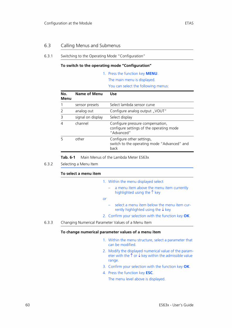
60
Configuration at the Module ETAS
6.3 Calling Menus and Submenus
6.3.1 Switching to the Operating Mode “Configuration”
To switch to the operating mode “Configuration”
1. Press the function key MENU.
The main menu is displayed.
You can select the following menus:
Tab. 6-1 Main Menus of the Lambda Meter ES63x
6.3.2 Selecting a Menu Item
To select a menu item
1. Within the menu displayed select
– a menu item above the menu item currently highlighted using the key
or
– select a menu item below the menu item cur-rently highlighted using the key
2. Confirm your selection with the function key OK.
6.3.3 Changing Numerical Parameter Values of a Menu Item
To change numerical parameter values of a menu item
1. Within the menu structure, select a parameter that can be modified.
2. Modify the displayed numerical value of the param-eter with the or key within the admissible value range.
3. Confirm your selection with the function key OK.
4. Press the function key ESC.
The menu level above is displayed.
No. Menu
Name of Menu Use
1 sensor presets Select lambda sensor curve
2 analog out Configure analog output „VOUT“
3 signal on display Select display
4 channel Configure pressure compensation,configure settings of the operating mode “Advanced”
5 other Configure other settings,switch to the operating mode “Advanced” and back
ES63x - User’s Guide
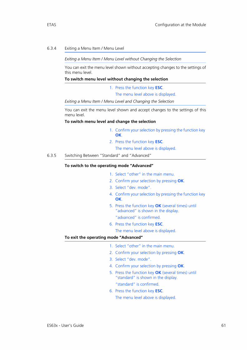
ETAS Configuration at the Module
6.3.4 Exiting a Menu Item / Menu Level
Exiting a Menu Item / Menu Level without Changing the Selection
You can exit the menu level shown without accepting changes to the settings ofthis menu level.
To switch menu level without changing the selection
1. Press the function key ESC.
The menu level above is displayed.
Exiting a Menu Item / Menu Level and Changing the Selection
You can exit the menu level shown and accept changes to the settings of thismenu level.
To switch menu level and change the selection
1. Confirm your selection by pressing the function key OK.
2. Press the function key ESC.
The menu level above is displayed.
6.3.5 Switching Between “Standard” and “Advanced”
To switch to the operating mode “Advanced”
1. Select “other” in the main menu.
2. Confirm your selection by pressing OK.
3. Select “dev. mode”.
4. Confirm your selection by pressing the function key OK.
5. Press the function key OK (several times) until “advanced” is shown in the display.
“advanced” is confirmed.
6. Press the function key ESC.
The menu level above is displayed.
To exit the operating mode “Advanced”
1. Select “other” in the main menu.
2. Confirm your selection by pressing OK.
3. Select “dev. mode”.
4. Confirm your selection by pressing OK.
5. Press the function key OK (several times) until “standard” is shown in the display.
“standard” is confirmed.
6. Press the function key ESC.
The menu level above is displayed.
ES63x - User’s Guide 61
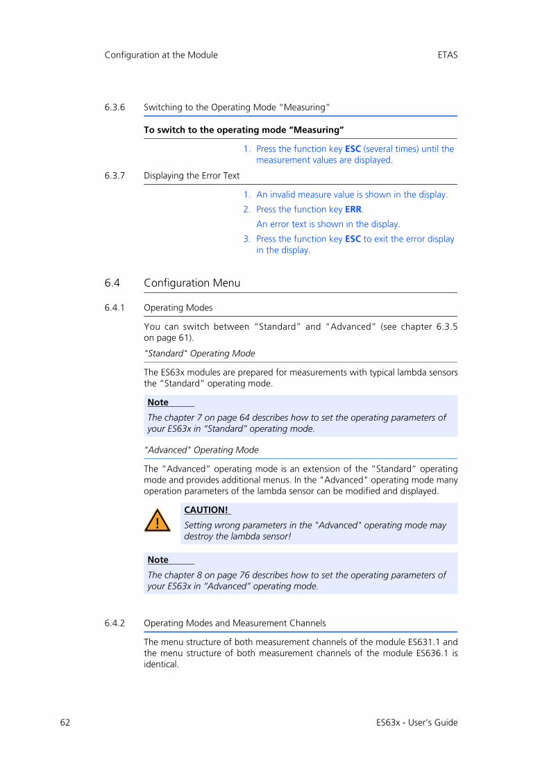
62
Configuration at the Module ETAS
6.3.6 Switching to the Operating Mode “Measuring”
To switch to the operating mode “Measuring”
1. Press the function key ESC (several times) until the measurement values are displayed.
6.3.7 Displaying the Error Text
1. An invalid measure value is shown in the display.
2. Press the function key ERR.
An error text is shown in the display.
3. Press the function key ESC to exit the error display in the display.
6.4 Configuration Menu
6.4.1 Operating Modes
You can switch between “Standard” and “Advanced” (see chapter 6.3.5on page 61).
"Standard" Operating Mode
The ES63x modules are prepared for measurements with typical lambda sensorsthe “Standard” operating mode.
"Advanced" Operating Mode
The “Advanced” operating mode is an extension of the “Standard” operatingmode and provides additional menus. In the "Advanced" operating mode manyoperation parameters of the lambda sensor can be modified and displayed.
6.4.2 Operating Modes and Measurement Channels
The menu structure of both measurement channels of the module ES631.1 andthe menu structure of both measurement channels of the module ES636.1 isidentical.
Note
The chapter 7 on page 64 describes how to set the operating parameters of your ES63x in “Standard” operating mode.
CAUTION!
Setting wrong parameters in the "Advanced" operating mode may destroy the lambda sensor!
Note
The chapter 8 on page 76 describes how to set the operating parameters of your ES63x in “Advanced” operating mode.
ES63x - User’s Guide
ETAS Configuration at the Module
6.4.3 Adjustable Parameters
The "Adjustable Parameters" chapter on page 182 gives an overview about thelimits and defaults of adjustable parameters.
ES63x - User’s Guide 63
64
Setting the Parameters (“Standard” Operating Mode) ETAS
7 Setting the Parameters (“Standard” Operating Mode)
This section describes how to set the operating parameters of your ES63x in“Standard” operating mode.
The menu items are described in the same order as they appear in the mainmenu.
• "[Menu 1]: sensor presets: Display of the Configurations of the Lambda Sensor" on page 65
• "[Menu 2]: analog out: Output Voltage at the Analog Output" on page 66
• "[Menu 3]: signal on display" on page 67
• "[Menu 4|1]: channel / pressure comp.: Automatic Pressure Compensa-tion" on page 68
• "[Menu 4|2]: channel / sensor detection" on page 69
• "[Menu 5]: other" on page 70
For a graphical representation of the ES63x configuration menu of the operatingmode "Standard" see chapter 15 on page 196.
ES63x - User’s Guide
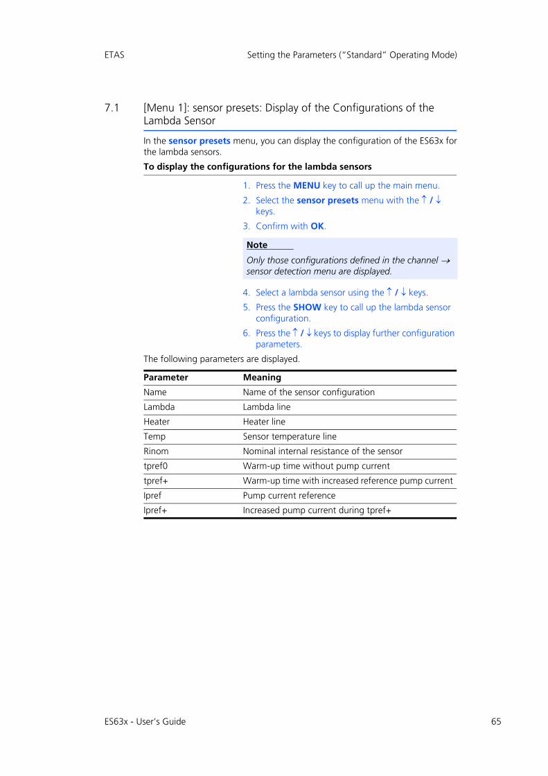
ETAS Setting the Parameters (“Standard” Operating Mode)
7.1 [Menu 1]: sensor presets: Display of the Configurations of the Lambda Sensor
In the sensor presets menu, you can display the configuration of the ES63x forthe lambda sensors.
To display the configurations for the lambda sensors
1. Press the MENU key to call up the main menu.
2. Select the sensor presets menu with the / keys.
3. Confirm with OK.
4. Select a lambda sensor using the / keys.
5. Press the SHOW key to call up the lambda sensor configuration.
6. Press the / keys to display further configuration parameters.
The following parameters are displayed.
Note
Only those configurations defined in the channel sensor detection menu are displayed.
Parameter Meaning
Name Name of the sensor configuration
Lambda Lambda line
Heater Heater line
Temp Sensor temperature line
Rinom Nominal internal resistance of the sensor
tpref0 Warm-up time without pump current
tpref+ Warm-up time with increased reference pump current
Ipref Pump current reference
Ipref+ Increased pump current during tpref+
ES63x - User’s Guide 65
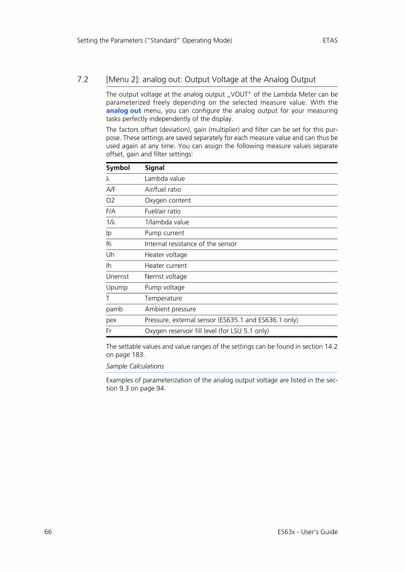
66
Setting the Parameters (“Standard” Operating Mode) ETAS
7.2 [Menu 2]: analog out: Output Voltage at the Analog Output
The output voltage at the analog output „VOUT“ of the Lambda Meter can beparameterized freely depending on the selected measure value. With theanalog out menu, you can configure the analog output for your measuringtasks perfectly independently of the display.
The factors offset (deviation), gain (multiplier) and filter can be set for this pur-pose. These settings are saved separately for each measure value and can thus beused again at any time. You can assign the following measure values separateoffset, gain and filter settings:
The settable values and value ranges of the settings can be found in section 14.2on page 183.
Sample Calculations
Examples of parameterization of the analog output voltage are listed in the sec-tion 9.3 on page 94.
Symbol Signal
Lambda value
A/F Air/fuel ratio
O2 Oxygen content
F/A Fuel/air ratio
1/ 1/lambda value
Ip Pump current
Ri Internal resistance of the sensor
Uh Heater voltage
Ih Heater current
Unernst Nernst voltage
Upump Pump voltage
T Temperature
pamb Ambient pressure
pex Pressure, external sensor (ES635.1 and ES636.1 only)
Fr Oxygen reservoir fill level (for LSU 5.1 only)
ES63x - User’s Guide
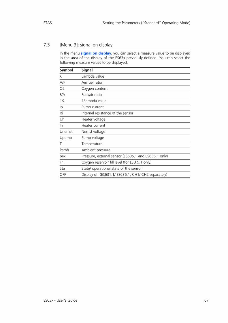
ETAS Setting the Parameters (“Standard” Operating Mode)
7.3 [Menu 3]: signal on display
In the menu signal on display, you can select a measure value to be displayedin the area of the display of the ES63x previously defined. You can select thefollowing measure values to be displayed:
Symbol Signal
Lambda value
A/F Air/fuel ratio
O2 Oxygen content
F/A Fuel/air ratio
1/ 1/lambda value
Ip Pump current
Ri Internal resistance of the sensor
Uh Heater voltage
Ih Heater current
Unernst Nernst voltage
Upump Pump voltage
T Temperature
Pamb Ambient pressure
pex Pressure, external sensor (ES635.1 and ES636.1 only)
Fr Oxygen reservoir fill level (for LSU 5.1 only)
Sta State/ operational state of the sensor
OFF Display off (ES631.1/ ES636.1: CH1/ CH2 separately)
ES63x - User’s Guide 67
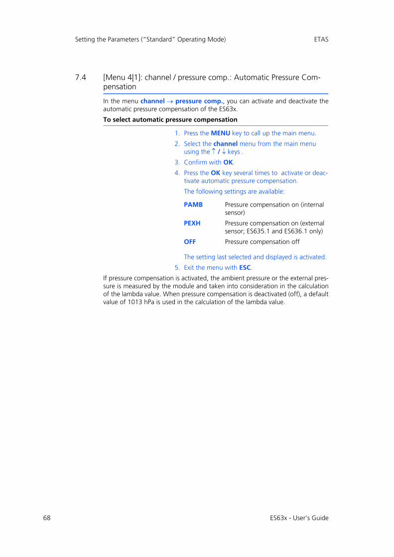
68
Setting the Parameters (“Standard” Operating Mode) ETAS
7.4 [Menu 4|1]: channel / pressure comp.: Automatic Pressure Com-pensation
In the menu channel pressure comp., you can activate and deactivate theautomatic pressure compensation of the ES63x.
To select automatic pressure compensation
1. Press the MENU key to call up the main menu.
2. Select the channel menu from the main menu using the / keys .
3. Confirm with OK.
4. Press the OK key several times to activate or deac-tivate automatic pressure compensation.
The following settings are available:
The setting last selected and displayed is activated.
5. Exit the menu with ESC.
If pressure compensation is activated, the ambient pressure or the external pres-sure is measured by the module and taken into consideration in the calculationof the lambda value. When pressure compensation is deactivated (off), a defaultvalue of 1013 hPa is used in the calculation of the lambda value.
PAMB Pressure compensation on (internal sensor)
PEXH Pressure compensation on (external sensor; ES635.1 and ES636.1 only)
OFF Pressure compensation off
ES63x - User’s Guide
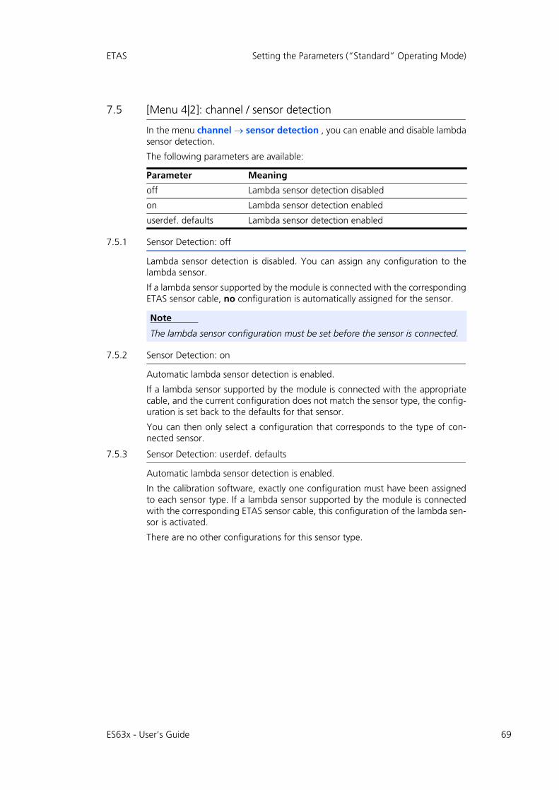
ETAS Setting the Parameters (“Standard” Operating Mode)
7.5 [Menu 4|2]: channel / sensor detection
In the menu channel sensor detection , you can enable and disable lambdasensor detection.
The following parameters are available:
7.5.1 Sensor Detection: off
Lambda sensor detection is disabled. You can assign any configuration to thelambda sensor.
If a lambda sensor supported by the module is connected with the correspondingETAS sensor cable, no configuration is automatically assigned for the sensor.
7.5.2 Sensor Detection: on
Automatic lambda sensor detection is enabled.
If a lambda sensor supported by the module is connected with the appropriatecable, and the current configuration does not match the sensor type, the config-uration is set back to the defaults for that sensor.
You can then only select a configuration that corresponds to the type of con-nected sensor.
7.5.3 Sensor Detection: userdef. defaults
Automatic lambda sensor detection is enabled.
In the calibration software, exactly one configuration must have been assignedto each sensor type. If a lambda sensor supported by the module is connectedwith the corresponding ETAS sensor cable, this configuration of the lambda sen-sor is activated.
There are no other configurations for this sensor type.
Parameter Meaning
off Lambda sensor detection disabled
on Lambda sensor detection enabled
userdef. defaults Lambda sensor detection enabled
Note
The lambda sensor configuration must be set before the sensor is connected.
ES63x - User’s Guide 69
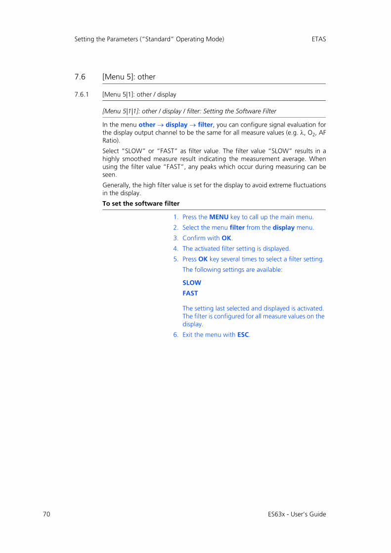
70
Setting the Parameters (“Standard” Operating Mode) ETAS
7.6 [Menu 5]: other
7.6.1 [Menu 5|1]: other / display
[Menu 5|1|1]: other / display / filter: Setting the Software Filter
In the menu other display filter, you can configure signal evaluation forthe display output channel to be the same for all measure values (e.g. , O2, AFRatio).
Select “SLOW” or “FAST” as filter value. The filter value “SLOW” results in ahighly smoothed measure result indicating the measurement average. Whenusing the filter value “FAST”, any peaks which occur during measuring can beseen.
Generally, the high filter value is set for the display to avoid extreme fluctuationsin the display.
To set the software filter
1. Press the MENU key to call up the main menu.
2. Select the menu filter from the display menu.
3. Confirm with OK.
4. The activated filter setting is displayed.
5. Press OK key several times to select a filter setting.
The following settings are available:
The setting last selected and displayed is activated. The filter is configured for all measure values on the display.
6. Exit the menu with ESC.
SLOW
FAST
ES63x - User’s Guide
ETAS Setting the Parameters (“Standard” Operating Mode)
[Menu 5|1|2]: other / display / resolution: Display Resolution
In the menu other display resolution, you set the number of decimalplaces for the measure data display.
To determine display resolution
1. Press the MENU key to call up the main menu.
2. Select the menu resolution from the display menu.
3. Confirm with OK.
4. Press the OK key several times to select a display resolution.
The following values are available:
5. Confirm with OK.
The display resolution is set accordingly.
6. Exit the menu with ESC.
For an overview of the display resolution of the measure values (number of dec-imal places), refer to section 14.5.1 on page 192.
COARSE Low display resolution
FINE High display resolution
ES63x - User’s Guide 71
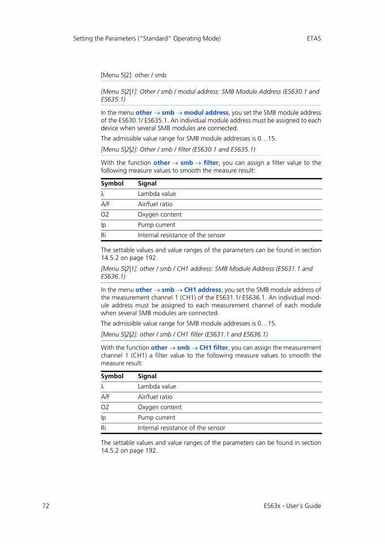
72
Setting the Parameters (“Standard” Operating Mode) ETAS
[Menu 5|2]: other / smb
[Menu 5|2|1]: Other / smb / modul address: SMB Module Address (ES630.1 and ES635.1)
In the menu other smb modul address, you set the SMB module addressof the ES630.1/ ES635.1. An individual module address must be assigned to eachdevice when several SMB modules are connected.
The admissible value range for SMB module addresses is 0…15.
[Menu 5|2|2]: Other / smb / filter (ES630.1 and ES635.1)
With the function other smb filter, you can assign a filter value to thefollowing measure values to smooth the measure result:
The settable values and value ranges of the parameters can be found in section14.5.2 on page 192.
[Menu 5|2|1]: other / smb / CH1 address: SMB Module Address (ES631.1 and ES636.1)
In the menu other smb CH1 address, you set the SMB module address ofthe measurement channel 1 (CH1) of the ES631.1/ ES636.1. An individual mod-ule address must be assigned to each measurement channel of each modulewhen several SMB modules are connected.
The admissible value range for SMB module addresses is 0…15.
[Menu 5|2|2]: other / smb / CH1 filter (ES631.1 and ES636.1)
With the function other smb CH1 filter, you can assign the measurementchannel 1 (CH1) a filter value to the following measure values to smooth themeasure result:
The settable values and value ranges of the parameters can be found in section14.5.2 on page 192.
Symbol Signal
Lambda value
A/F Air/fuel ratio
O2 Oxygen content
Ip Pump current
Ri Internal resistance of the sensor
Symbol Signal
Lambda value
A/F Air/fuel ratio
O2 Oxygen content
Ip Pump current
Ri Internal resistance of the sensor
ES63x - User’s Guide
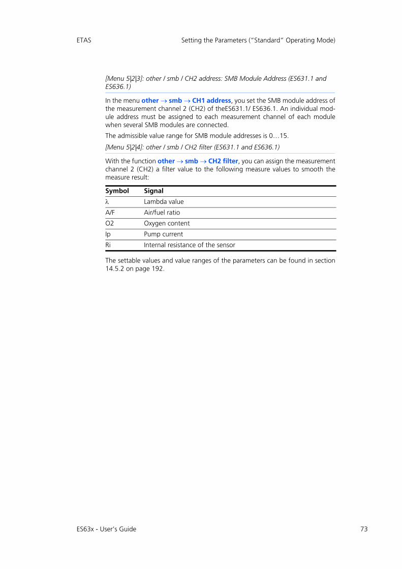
ETAS Setting the Parameters (“Standard” Operating Mode)
[Menu 5|2|3]: other / smb / CH2 address: SMB Module Address (ES631.1 and ES636.1)
In the menu other smb CH1 address, you set the SMB module address ofthe measurement channel 2 (CH2) of theES631.1/ ES636.1. An individual mod-ule address must be assigned to each measurement channel of each modulewhen several SMB modules are connected.
The admissible value range for SMB module addresses is 0…15.
[Menu 5|2|4]: other / smb / CH2 filter (ES631.1 and ES636.1)
With the function other smb CH2 filter, you can assign the measurementchannel 2 (CH2) a filter value to the following measure values to smooth themeasure result:
The settable values and value ranges of the parameters can be found in section14.5.2 on page 192.
Symbol Signal
Lambda value
A/F Air/fuel ratio
O2 Oxygen content
Ip Pump current
Ri Internal resistance of the sensor
ES63x - User’s Guide 73

74
Setting the Parameters (“Standard” Operating Mode) ETAS
7.6.2 [Menu 5|3]: other / dev. mode: Operating Modes
In the menu other dev. mode, you can choose between the opreatingmodes “Standard” and “Advanced” of the ES63x. The operating mode“Advanced” is an extension of the operating mode “Standard” and providesadditional menus and functions.
To select the operating mode
1. Press the MENU key to call up the main menu.
2. Select the dev. mode menu from the other menu.
3. Confirm with OK.
4. The activated operating mode is displayed.
5. Press the OK key several times to select an operat-ing mode.
The following settings are available:
The setting last selected and displayed is activated.
6. Exit the menu with ESC.
STANDARD
ADVANCED
ES63x - User’s Guide
ETAS Setting the Parameters (“Standard” Operating Mode)
7.6.3 [Menu 5|4]: other / factory init: Default Configuration
In the menu other factory init , you can reset the settings of the module totheir default configuration if the factory default configurations of the modulehave been changed.
The default configuration of the module with the device-specific default valuesto which the parameters are reset is listed in the overview of all menu parametersin chapter 14 on page 182.
Resetting to the Default Configuration
The default configuration is reset when you confirm the selection reset todefault; confirming the selection cancel enables you to exit the menu withoutany changes.
7.6.4 [Menu 5|5]: other / version: Displaying Firmware Version and Serial Numbers
With the menu other version, information on the firmware and the serialnumbers is displayed simultaneously.
Note
The same device-specific default values apply for the ES63x and for the ES63x-4.9.
Note
The following settings are not reset if they have been changed by the user:- lambda line- heater line- temperature line
ES63x - User’s Guide 75
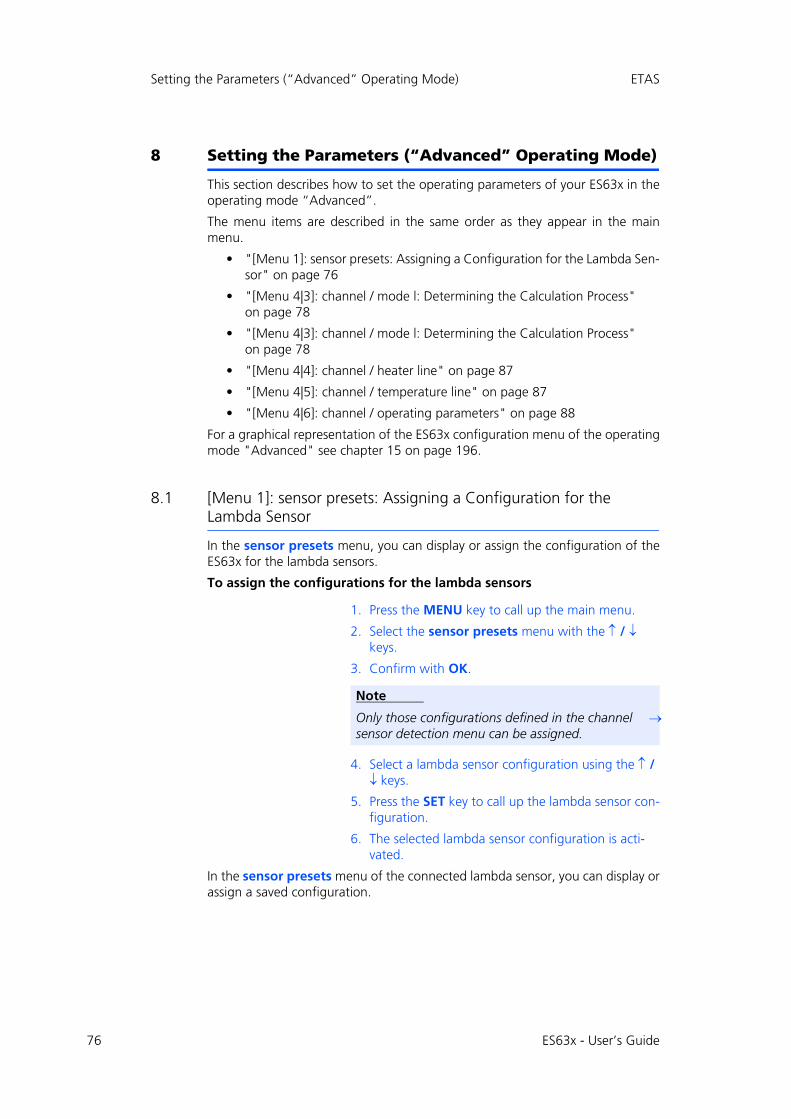
76
Setting the Parameters (“Advanced” Operating Mode) ETAS
8 Setting the Parameters (“Advanced” Operating Mode)
This section describes how to set the operating parameters of your ES63x in theoperating mode “Advanced”.
The menu items are described in the same order as they appear in the mainmenu.
• "[Menu 1]: sensor presets: Assigning a Configuration for the Lambda Sen-sor" on page 76
• "[Menu 4|3]: channel / mode l: Determining the Calculation Process" on page 78
• "[Menu 4|3]: channel / mode l: Determining the Calculation Process" on page 78
• "[Menu 4|4]: channel / heater line" on page 87
• "[Menu 4|5]: channel / temperature line" on page 87
• "[Menu 4|6]: channel / operating parameters" on page 88
For a graphical representation of the ES63x configuration menu of the operatingmode "Advanced" see chapter 15 on page 196.
8.1 [Menu 1]: sensor presets: Assigning a Configuration for the Lambda Sensor
In the sensor presets menu, you can display or assign the configuration of theES63x for the lambda sensors.
To assign the configurations for the lambda sensors
1. Press the MENU key to call up the main menu.
2. Select the sensor presets menu with the / keys.
3. Confirm with OK.
4. Select a lambda sensor configuration using the / keys.
5. Press the SET key to call up the lambda sensor con-figuration.
6. The selected lambda sensor configuration is acti-vated.
In the sensor presets menu of the connected lambda sensor, you can display orassign a saved configuration.
Note
Only those configurations defined in the channel sensor detection menu can be assigned.
ES63x - User’s Guide

ETAS Setting the Parameters (“Advanced” Operating Mode)
The following configurations are available:
• 4.2-80
• 4.2/4.7
• 4.9
• ADV
• ADV-D
• ZFAS-U2
• ZFAS-U2-D
• 5.1
• 4.2-80-old
• 4.2/4.7-old
• ZFAS-U3
• 5.2
• 4.2-80 analytic
• 4.2/4.7 analytic
• 4.9-300 analytic
• ADV analytic
• ADV-D analytic
• 5.1 analytic
• 4.2-80-old analytic
• 4.2/4.7-old analytic
• 5.2 analytic
If the user has defined additional configurations, these are also displayed.
ES63x - User’s Guide 77
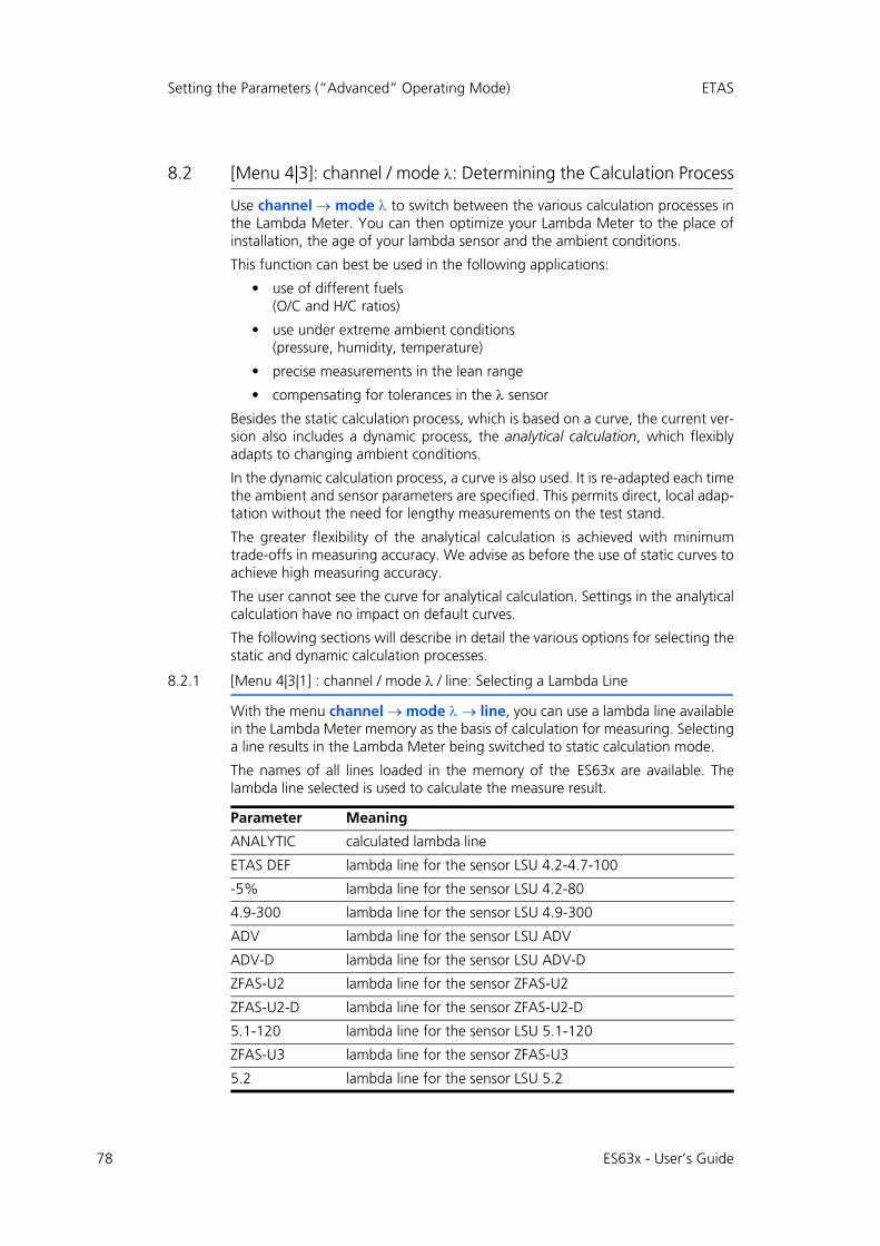
78
Setting the Parameters (“Advanced” Operating Mode) ETAS
8.2 [Menu 4|3]: channel / mode : Determining the Calculation Process
Use channel mode to switch between the various calculation processes inthe Lambda Meter. You can then optimize your Lambda Meter to the place ofinstallation, the age of your lambda sensor and the ambient conditions.
This function can best be used in the following applications:
• use of different fuels (O/C and H/C ratios)
• use under extreme ambient conditions (pressure, humidity, temperature)
• precise measurements in the lean range
• compensating for tolerances in the sensor
Besides the static calculation process, which is based on a curve, the current ver-sion also includes a dynamic process, the analytical calculation, which flexiblyadapts to changing ambient conditions.
In the dynamic calculation process, a curve is also used. It is re-adapted each timethe ambient and sensor parameters are specified. This permits direct, local adap-tation without the need for lengthy measurements on the test stand.
The greater flexibility of the analytical calculation is achieved with minimumtrade-offs in measuring accuracy. We advise as before the use of static curves toachieve high measuring accuracy.
The user cannot see the curve for analytical calculation. Settings in the analyticalcalculation have no impact on default curves.
The following sections will describe in detail the various options for selecting thestatic and dynamic calculation processes.
8.2.1 [Menu 4|3|1] : channel / mode / line: Selecting a Lambda Line
With the menu channel mode line, you can use a lambda line availablein the Lambda Meter memory as the basis of calculation for measuring. Selectinga line results in the Lambda Meter being switched to static calculation mode.
The names of all lines loaded in the memory of the ES63x are available. Thelambda line selected is used to calculate the measure result.
Parameter Meaning
ANALYTIC calculated lambda line
ETAS DEF lambda line for the sensor LSU 4.2-4.7-100
-5% lambda line for the sensor LSU 4.2-80
4.9-300 lambda line for the sensor LSU 4.9-300
ADV lambda line for the sensor LSU ADV
ADV-D lambda line for the sensor LSU ADV-D
ZFAS-U2 lambda line for the sensor ZFAS-U2
ZFAS-U2-D lambda line for the sensor ZFAS-U2-D
5.1-120 lambda line for the sensor LSU 5.1-120
ZFAS-U3 lambda line for the sensor ZFAS-U3
5.2 lambda line for the sensor LSU 5.2
ES63x - User’s Guide

ETAS Setting the Parameters (“Advanced” Operating Mode)
8.2.2 [Menu 4|3|2] : channel / mode / analytic: Adapting Fuel and Environment
The channel mode analytic submenu contains a dynamic function tomatch the calculation process. It takes into account various climatic conditions aswell as the use of various fuel mixtures.
The analytical calculation process rematches the curve used after you have set allthe parameters.
[Menu 4|3|2|1]: channel / mode / analytic / fuel: Fuel Composition
channel mode analytic fuel helps you to set a number of parame-ters which characterize the fuel mixture used. When you calculate the lambdavalue according to Brettschneider, you can compensate for the H/C ratio of vari-ous fuel types.
Many countries also use fuels that contain various amounts and strengths ofalcohol. Now you can compensate for the characteristic O/C ratio and the waterproportion in the calculation. You will find sample calculations at the end of thissection.
As a further characteristic of the fuel, you can set the stoichiometric air/fuel ratio.This becomes a fixed value in the calculation.
All the other changes in the fuel mixture influence the calculation of the lambdavalue and the air/fuel ratio.
The following parameters are available:
The measure units, default values and value ranges listed in section 14.4.4on page 188 apply for fuel composition.
Examples of fuel composition are calculated in section 9.4.1 on page 96.
[Menu 4|3|2|2]: channel / mode / analytic / climatic conditions: Climatic Condi-tions
Use channel mode analytic climatic conditions to set anothergroup of parameters. They will act as the basis for the analytical calculation ofthe lambda value, the environmental conditions.
Among climatic conditions, air pressure has a major impact on the measuringaccuracy of the lambda sensor. Since the sensor doesn't actually measure theoxygen content in the exhaust gas but the partial oxygen pressure, deviations willarise rapidly, especially during altitude tests.
Note
Ensure that the settings for internal resistance and pumped reference also apply to the sensor used (cf. section 5.7.2 on page 55).
Parameter Meaning Unit
H/C Ratio of hydrogen/carbon mol/mol
O/C Ratio of oxygen/carbon mol/mol
H2O Water proportion mmol/mol
AFSt. Stoichiometric ratio kg/kg
ES63x - User’s Guide 79

80
Setting the Parameters (“Advanced” Operating Mode) ETAS
When the pressure compensation function is activated, deviations due to ambi-ent pressure can be compensated with the measure values of the module’s inter-nal pressure sensor or with the measure values of an external pressure sensor(see section 3.4.2 on page 25).
In addition, relative humidity has an impact on measuring accuracy in the leanrange, although to a lesser extent. Similarly, air temperature is also included inthe calculation of absolute relative humidity.
All other changes in the environmental conditions have an impact on the calcu-lation of the lambda value and the air/fuel ratio. Ambient pressure has an indirectimpact through the oxygen content measurement.
The following parameters are available for setting the climatic conditions:
The measure units, default values and value ranges listed in section 14.4.4on page 188 apply for the climatic conditions.
8.2.3 [Menu 4|3|3]: channel / mode / advanced: Adapting Combustion and Sensor
In submenu channel mode advanced, you can carry out a dynamicadaptation of the calculation process for measuring mode.
Due to the high theoretical requirements linked to the use of this calculationmethod, it should only be used by advanced users who have the necessary basicknowledge for making settings in this field.
In this section, you can set parameters that describe the hydrogen residues in theexhaust gas, the deviation of the sensor used and the special water-gas equilib-rium of the combustion engine.
The individual factors are compensated when the curve is calculated. TheLambda Meter can then be used for high-precision measurements which takeeven the slightest deviations into account.
You can enter directly the sensor curve as a measurement result. You can also usethe Lambda Meter to measure a sensor. In both cases, you must have the neces-sary resources (reference gas).
Hydrogen residue in the exhaust gas and the water-gas equilibrium temperaturecan be determined by making measurements. You can then enter your measur-ing results in the Lambda Meter.
The hydrogen residues from combustion, the special sensor sensitivity and thewater-gas equilibrium temperature all impact on the lambda value calculationand the air/fuel ratio. Changes mainly have a direct, but sometimes indirect,effect on the measurement of the oxygen content.
The water-gas equilibrium temperature only has an impact in the rich range ofthe measuring result. In the range =1, it is as negligible as in the lean range.
[Menu 4|3|3|1]: channel / mode / advanced / H2 shift: Hydrogen Shift
channel mode advanced H2 shift lets you set the sensor's hydro-gen shift. It is used as a basis for performing the analytical calculation of thelambda value.
Parameter Meaning
humidity Relative humidity
air temp Air temperature
ES63x - User’s Guide

ETAS Setting the Parameters (“Advanced” Operating Mode)
The hydrogen shift occurs due to hydrogen residue in the exhaust gas. Such res-idue can be found even in complete combustion. Due to its physical process, theLSU sensor has a hydrogen cross-sensitivity.
Hydrogen residue in the exhaust gas can therefore lead to measuring result devi-ations. Ideally, the sensor's zero current is =1 if the sensor deviation isneglected. In reality, a higher lambda value must be assumed for the zero current(the default is 1.009). An exhaust gas analysis is required to determine thelambda value.
.
Fig. 8-1 How to Correct Hydrogen Shift
To calculate the hydrogen shift, an upper limit, a lower limit, and a mean devia-tion are used. The lower limit (lower th) is situated in the rich range anddenotes the point from which the real values deviate from the ideal values. Theupper limit (upper th) is situated in the lean range and denotes the point atwhich the real values are identical with the ideal values. The mean deviation(avg th) is the point at which the sensor supplies no signal.
To correct hydrogen shift, adapt the curve by changing the interval defined bythe upper and lower limits. The mean deviation acts as the parameter for inter-polating the actual lambda value.
The following parameters are available for setting the hydrogen shift:
The settable values and value ranges of the parameters can be found in section14.4.5 on page 188.
Parameter Meaning
lower th Lower limit H2 shift
at Ip=0 Mean H2 shift
upper th Upper limit H2 shift
ES63x - User’s Guide 81

82
Setting the Parameters (“Advanced” Operating Mode) ETAS
[Menu 4|3|3|2]: channel / mode / advanced / sensor calibration: Setting Sensor Characteristics
Use channel mode advanced sensor calibration input to setthe sensor curve. It is used as the basis for the analytical calculation of thelambda value.
The sensor curve is sensed separately mainly as an age-linked deviation of theindividual measuring accuracy of the sensor in the rich and lean ranges. In bothcases, you can use measurements in reference gas to determine the correctionfactor by which the sensor signal is multiplied in each range.
In addition, the zero current deviation of each sensor can be corrected to com-pensate for individual features. The actual pump current of the sensor is mea-sured in pure nitrogen. The value set here is included as a deviation in the lambdavalue calculation.
This section describes how to enter your measuring results for the sensor curveby hand. You can also measure your sensor using the Lambda Meter and acceptthe measuring results directly as correction factors. You'll find more informationabout this in the next section.
The following parameters are available for setting the sensor characteristics:
The settable values and value ranges of the parameters can be found in section14.4.5 on page 188.
[Menu 4|3|3|2]: channel / mode / advanced / sensor calibration: Measuring Sen-sor Characteristics
Use channel mode advanced sensor calibration ref. gas tomeasure the sensor curve. It acts as the basis for the analytical calculation of thelambda value.
The parameters used are the correction factors described in the previous section:deviation in lean and rich ranges, and sensor zero current deviation.
The sensor sensitivity in the lean range can be determined using the ambient airor a different oxygen mixture. The ambient air has an assumed oxygen contentof 20.95 % and can be adjusted on a case-by-case basis. The actual valuedepends on temperature and relative air humidity. You will find calculation exam-ples at the end of this section.
The sensor sensitivity in the rich range can be determined from known referencegases where the CO and H2 concentrations in each case are available as inputparameters to determine the reference gas.
The zero current compensation must take place in pure nitrogen. This requires anitrogen content of 99.999 %.
When you use nitrogen and a reference gas for the rich range, you should alwaysuse a washing bottle. The volumetric flow should be 2 l/min.
Parameter Meaning
lean scale Sensor deviation, lean
rich scale Sensor deviation, rich
zero offset Sensor deviation, zero current
ES63x - User’s Guide
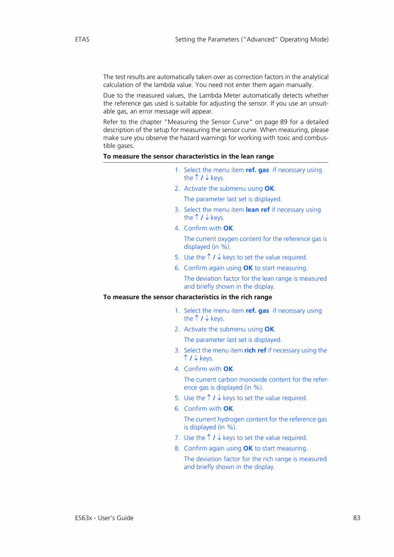
ETAS Setting the Parameters (“Advanced” Operating Mode)
The test results are automatically taken over as correction factors in the analyticalcalculation of the lambda value. You need not enter them again manually.
Due to the measured values, the Lambda Meter automatically detects whetherthe reference gas used is suitable for adjusting the sensor. If you use an unsuit-able gas, an error message will appear.
Refer to the chapter "Measuring the Sensor Curve" on page 89 for a detaileddescription of the setup for measuring the sensor curve. When measuring, pleasemake sure you observe the hazard warnings for working with toxic and combus-tible gases.
To measure the sensor characteristics in the lean range
1. Select the menu item ref. gas if necessary using the / keys.
2. Activate the submenu using OK.
The parameter last set is displayed.
3. Select the menu item lean ref if necessary using the / keys.
4. Confirm with OK.
The current oxygen content for the reference gas is displayed (in %).
5. Use the / keys to set the value required.
6. Confirm again using OK to start measuring.
The deviation factor for the lean range is measured and briefly shown in the display.
To measure the sensor characteristics in the rich range
1. Select the menu item ref. gas if necessary using the / keys.
2. Activate the submenu using OK.
The parameter last set is displayed.
3. Select the menu item rich ref if necessary using the / keys.
4. Confirm with OK.
The current carbon monoxide content for the refer-ence gas is displayed (in %).
5. Use the / keys to set the value required.
6. Confirm with OK.
The current hydrogen content for the reference gas is displayed (in %).
7. Use the / keys to set the value required.
8. Confirm again using OK to start measuring.
The deviation factor for the rich range is measured and briefly shown in the display.
ES63x - User’s Guide 83

84
Setting the Parameters (“Advanced” Operating Mode) ETAS
The procedure in the rich range only differs in the composition of the referencegas. When compensating in the rich range, enter both the CO concentration andthe H2 concentration.
To simplify operating the device, the sensor curve for the lean range is alwaysadopted automatically in the rich range when a new value is set for lean scale.
If you want to enter a separate correction value for the rich range, make sure youobserve the operating sequence: always set the value for lean scale first andthen the value for rich scale.
No input is required for zero current compensation since the gas composition isa fixed figure.
Calculation example: Oxygen content: An idea l oxygen content o f20.95 % is assumed. In the next example, the ambient temperature is specifiedas 23° C and relative humidity as 50 %.
At 23° C, the saturation vapor pressure of air is 3 %, the absolute humidity isabout 3 % * 50 % = 1.5 %.
Since oxygen can only occur in air that is actually present, the actual oxygencontent is calculated as follows:
20.95 % * (1 - 0.015) = 20.64 %
Fig. 8-2 illustrates the relationship between temperature and the saturationvapor pressure of ambient air.
Fig. 8-2 Saturation Vapor Pressure of Dry Air
[Menu 4|3|3|3]: channel / mode / advanced / TDET: Water-Gas Equilibrium Tem-perature
Use channel mode advanced TDET to enter the water-gas equilib-rium temperature, TDET, which is used as the basis for the analytical calculationof the lambda value.
When the water-gas equilibrium is fully set, this value is 1212 °C. Deviationsfrom this temperature impact on accuracy in the rich range.
The relationship between the water-gas equilibrium temperature, TDET, and thecustomary factor kp found in the literature is explained in the equation below.
kp 101 93 2040
TDET 273+------------------------------–
=
ES63x - User’s Guide

ETAS Setting the Parameters (“Advanced” Operating Mode)
The settable values and value ranges of the parameters can be found in section14.4.5 on page 188.
[Menu 4|3|3|4]: channel / mode / advanced / IPC:
In case of longer operation of some sensors in lean environment, inaccuracycaused by fatigue can occur. This sensors can to be regenerated by operatingwith inverse pump current (PUK).
The operating mode is also called Inverse Pump Current Cycle (IPC).
In the Auto IPC mode (automatic inverse pump current mode) the module eval-uates characteristic parameters for the fatigue of the sensor, and regenerates thesensor automatically, if necessary.
Use channel mode advanced IPC Auto IPC to enable or disablethe Auto IPC mode.
To select automatic inverse pump current mode
1. Press the MENU key to call up the main menu.
2. Select the channel mode advanced IPC Auto IPC menu from the main menu using the / and OK keys.
3. Press the OK key several times to activate or deacti-vate automatic inverse pump current mode.
The following settings are available:
The setting last selected and displayed is activated.
4. Exit the menu with ESC.
Use channel mode advanced IPC Start IPC cycle to start an sin-gle IPC cycle.
To start a single inverse pump current cycle
1. Press the MENU key to call up the main menu.
2. Select the channel mode advanced IPC Start IPC cycle menu from the main menu using the / and OK keys.
3. Press the OK key to start a inverse pump current cycle.
4. Exit the menu with ESC.
Note
Only the lambda sensors LSU4.9, LSU5.1and LSU 5.2 can be used in inverse pump current operating mode.
On Automatic inverse pump current mode on
Off Automatic inverse pump current mode off
ES63x - User’s Guide 85
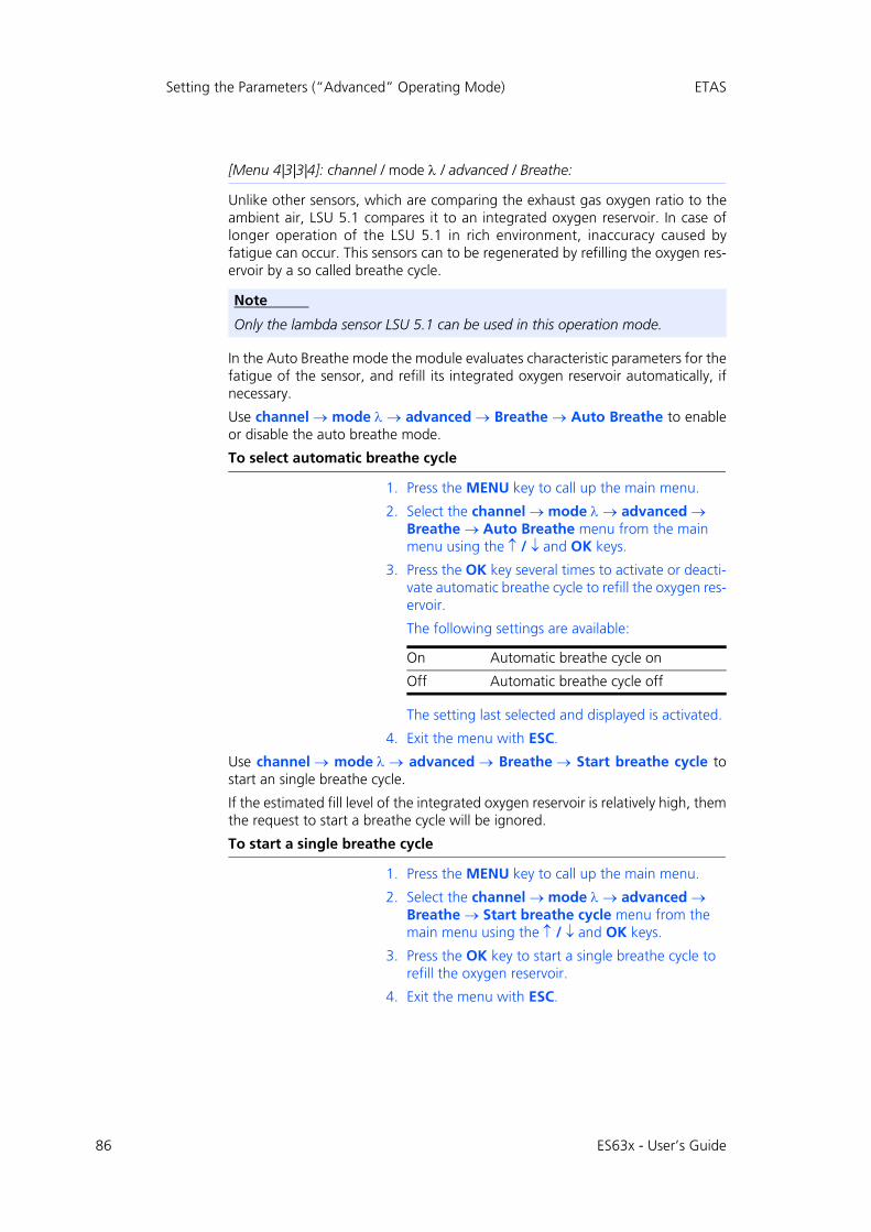
86
Setting the Parameters (“Advanced” Operating Mode) ETAS
[Menu 4|3|3|4]: channel / mode / advanced / Breathe:
Unlike other sensors, which are comparing the exhaust gas oxygen ratio to theambient air, LSU 5.1 compares it to an integrated oxygen reservoir. In case oflonger operation of the LSU 5.1 in rich environment, inaccuracy caused byfatigue can occur. This sensors can to be regenerated by refilling the oxygen res-ervoir by a so called breathe cycle.
In the Auto Breathe mode the module evaluates characteristic parameters for thefatigue of the sensor, and refill its integrated oxygen reservoir automatically, ifnecessary.
Use channel mode advanced Breathe Auto Breathe to enableor disable the auto breathe mode.
To select automatic breathe cycle
1. Press the MENU key to call up the main menu.
2. Select the channel mode advanced Breathe Auto Breathe menu from the main menu using the / and OK keys.
3. Press the OK key several times to activate or deacti-vate automatic breathe cycle to refill the oxygen res-ervoir.
The following settings are available:
The setting last selected and displayed is activated.
4. Exit the menu with ESC.
Use channel mode advanced Breathe Start breathe cycle tostart an single breathe cycle.
If the estimated fill level of the integrated oxygen reservoir is relatively high, themthe request to start a breathe cycle will be ignored.
To start a single breathe cycle
1. Press the MENU key to call up the main menu.
2. Select the channel mode advanced Breathe Start breathe cycle menu from the main menu using the / and OK keys.
3. Press the OK key to start a single breathe cycle to refill the oxygen reservoir.
4. Exit the menu with ESC.
Note
Only the lambda sensor LSU 5.1 can be used in this operation mode.
On Automatic breathe cycle on
Off Automatic breathe cycle off
ES63x - User’s Guide
ETAS Setting the Parameters (“Advanced” Operating Mode)
8.3 [Menu 4|4]: channel / heater line
In the menu channel heater line , you can select different heater lines toadapt the heater control perfectly to your application. The lambda sensor isheated in accordance with this line.
The following heater lines can be selected:
If the user has defined additional heater lines, these are also displayed.
The heater lines that can be set are listed in section 14.4.6 on page 190.
8.4 [Menu 4|5]: channel / temperature line
In the menu channel temperature line , you can select different tempera-ture lines. This line determines the correlation between the measured internalresistance and the temperature of the lambda sensor.
Without a valid temperature line, the temperature of the lambda sensor cannotbe measured and the measure value “Temperature” is set to an invalid value.
The following temperature lines can be selected:
If the user has defined additional temperature lines, these are also displayed.
The temperature lines that can be set are listed in section 14.4.7 on page 190.
Parameter Meaning
ETAS DEF Heater line for the sensors LSU 4.2-80 and LSU 4.2-4.7-100
HtUp-300 Heater line for the sensor LSU 4.9-300
ADV Heater line for the sensor LSU ADV
ZFAS-U2/D Heater line for the sensors ZFAS-U2 and ZFAS-D
HtUp-5.1 Heater line for the sensor LSU 5.1
HtUp-4.2 Heater line for the sensors LSU 4.2-80 and LSU 4.2-4.7-100
ZFAS-U3 Heater line for the sensor ZFAS-U3
HtUp-5.2 Heater line for the sensor LSU 5.2
Parameter Meaning
T-4.2-100 Temperature line for the sensor LSU 4.2-4.7-100
T-4.2-80 Temperature line for the sensor LSU 4.2-80
T-4.9-300 Temperature line for the sensor LSU 4.9-300
T-ADV Temperature line for the sensor LSU ADV
T-ADV-D Temperature line for the sensor LSU ADV-D
T-ZFAS-U2/D Temperature line for the sensors ZFAS-U2 and ZFAS-D
T-5.1-120 Temperature line for the sensor LSU 5.1
T-ZFAS-U3 Temperature line for the sensor ZFAS-U3
T-5.2 Temperature line for the sensor LSU 5.2
ES63x - User’s Guide 87
88
Setting the Parameters (“Advanced” Operating Mode) ETAS
8.5 [Menu 4|6]: channel / operating parameters
If you are operating your Lambda Meter with a lambda sensor whose settings arenot saved in the default configuration of the ES63x, you can set nominal valuesfor your lambda sensor in the menu channel operating parameters. Youcan adjust its parameters when lambda sensor detection is disabled.
The following parameters can be adapted:
The settable values and value ranges of the parameters can be found in section14.4.8 on page 191. ´
Parameter Meaning
Ri,nom Nominal internal resistance of the sensor
k rich Coefficient for pressure dependence of pump current at lambda < 1
k lean Coefficient for pressure dependence of pump current at lambda > 1
Ip,ref Current intensity for pumped reference of the lambda sensor
Ip,ref+ Increased pump current during tpref+
tp,ref0 Warm-up time without pump current
tp,ref+ Warm-up time with increased reference pump current
Note
Ensure that the settings for pumped reference and lambda line also apply to the sensor used (cf. section 5.7.2 on page 55).
Note
Ensure that the settings for internal resistance and lambda line also apply to the sensor used (cf. section 5.7.2 on page 55).
ES63x - User’s Guide

ETAS Instructions and Sample Calculations
9 Instructions and Sample Calculations
This chapter contains information on the following topics:
• "Measuring the Sensor Curve" on page 89
• "Calibrate to Air" on page 93
• "Parameterizing the Analog Output Voltage" on page 94
• "Sample Calculations" on page 96
9.1 Measuring the Sensor Curve
You can carry out high-precision measurements in which the precise sensor curveis included in the lambda value calculation. First the characteristic of the con-nected sensor is saved in the Lambda Meter.
If you know the sensor curve, you can enter it directly in the Lambda Module.You can also use the Lambda Meter as a measuring instrument to measure thesensor curve and then accept the determined values to continue work.
Chapter 8.2.3 on page 80 describes the work steps for measuring the sensorcurve. This chapter contains a description of the test setup for measuring individ-ual values.
Normally, single-point adjustment is sufficient for the sensor in the lean range toachieve high measuring accuracy when measuring the sensor curve. To compen-sate for minor tolerances, you can carry out additional adjustment for the richrange and zero current.
A basic setup is required for the measurements where all three measuring pointsare identical:
• ES63x Lambda Module
• power supply cable
• power supply
• Lambda sensor
• sensor cable
• fitting through which the measuring gas flows, with M18 * 1.5 thread for the sensor
• connecting tubes
In addition to this basic setup, other setups are required depending on the mea-suring point. They are listed and illustrated below in the description of test setupsfor each of the measuring points.
When you measure the sensor curve, your readings are automatically taken overas correction factors for the analytical calculation of the lambda value. The mea-sured values are shown on the display.
Each sensor requires its own adjustment parameters. For this reason, you shouldcarry out a recalibration each time the lambda sensor is changed.
The sections below describe the setup for measuring the sensor curve at each ofthe measuring points. The basic setup described above is used for all measuringpoints.
ES63x - User’s Guide 89
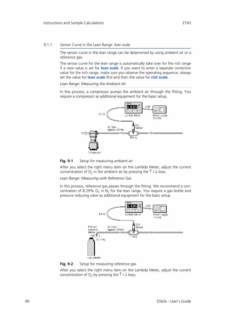
90
Instructions and Sample Calculations ETAS
9.1.1 Sensor Curve in the Lean Range: lean scale
The sensor curve in the lean range can be determined by using ambient air or areference gas.
The sensor curve for the lean range is automatically take over for the rich rangeif a new value is set for lean scale. If you want to enter a separate correctionvalue for the rich range, make sure you observe the operating sequence: alwaysset the value for lean scale first and then the value for rich scale.
Lean Range: Measuring the Ambient Air
In this process, a compressor pumps the ambient air through the fitting. Yourequire a compressor as additional equipment for the basic setup.
Fig. 9-1 Setup for measuring ambient air
After you select the right menu item on the Lambda Meter, adjust the currentconcentration of O2 in the ambient air by pressing the / keys.
Lean Range: Measuring with Reference Gas
In this process, reference gas passes through the fitting. We recommend a con-centration of 8.29% O2 in N2 for the lean range. You require a gas bottle andpressure reducing valve as additional equipment for the basic setup.
Fig. 9-2 Setup for measuring reference gas
After you select the right menu item on the Lambda Meter, adjust the currentconcentration of O2 by pressing the / keys.
ES63x - User’s Guide

ETAS Instructions and Sample Calculations
9.1.2 Sensor Curve in Rich Range: rich scale
To measure the sensor curve in the rich range, a reference gas is pumped throughthe fitting via a washing bottle. We recommend a gas mixture of 4.1% CO and3.2% H2 in N2.
The following equipment is required in addition to the basic setup:
• gas bottle with pressure reducer and washing bottle
• extractor hood and
• breathing apparatus not requiring ambient air in case of emergency.
Fig. 9-3 Setup for measuring CO gas
After you select the right menu item on the Lambda Meter, adjust the currentconcentration of CO in the reference gas by pressing the / keys. Then adjustthe concentration of H2 in the reference gas in the same way.
Note
CO gas is a highly combustible gas that is poisonous if inhaled.Make sure the rooms where you are working are sufficiently ventilated or work under an extractor hood. Do not smoke when handling CO gas. Breathing apparatus not requiring ambient air should be kept at hand in case of an emergency.
ES63x - User’s Guide 91
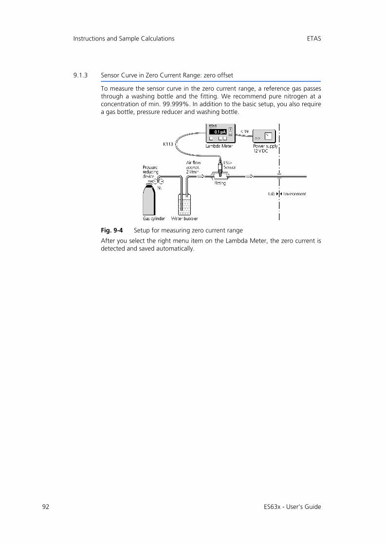
92
Instructions and Sample Calculations ETAS
9.1.3 Sensor Curve in Zero Current Range: zero offset
To measure the sensor curve in the zero current range, a reference gas passesthrough a washing bottle and the fitting. We recommend pure nitrogen at aconcentration of min. 99.999%. In addition to the basic setup, you also requirea gas bottle, pressure reducer and washing bottle.
Fig. 9-4 Setup for measuring zero current range
After you select the right menu item on the Lambda Meter, the zero current isdetected and saved automatically.
ES63x - User’s Guide
ETAS Instructions and Sample Calculations
9.2 Calibrate to Air
A semi-automatic calibration of the sensor / Lambda Module system can be car-ried out in the calibration software.
Applications:
• Compensation of tolerances of the lambda sensor,
• Compensation of aging effects of the lambda sensor (can still be used in spite of a weaker signal) and
• Determination of whether a sensor deviates from the desired values.
Normal ambient air is used as air reference. To be able to execute a correct cali-bration in extreme atmospheric pressure or temperature conditions, a differentvalue from the default value of 20.9% can be entered as desired oxygen value.
To calibrate the system to air
1. Ensure that the sensor is operated in air or that any residual exhaust gas has been blown out, e.g. using compressed air.
2. If the exact concentration of oxygen is not known, use the default value 20.9%.
3. Switch on the supply voltage of the Lambda Mod-ule and the sensor.
4. Check that all parameters for activating heater con-trol are fulfilled (see section 4.4.2 on page 38).
5. Check in the diagnostics section of the calibration software whether “Ri” is marked in green.
The sensor is sufficiently heated. TheLambda Mod-ule / sensor system is ready for operation.
Note
The correction factor determined is sensor-specific and is stored in the module. If a different lambda sensor is connected, the correction factor has to be reset and a new system calibration executed. On calibration, the factors are also stored in TEDS for LSU ADV-D and LSU 5.1, and are reloaded from TEDS to the module when the sensor is connected (i.e. the system does not need recalibra-tion if the sensor was previously correctly calibrated).
ES63x - User’s Guide 93
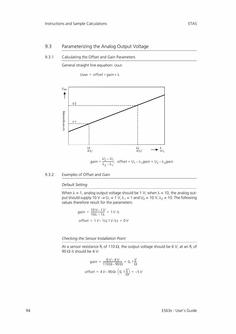
94
Instructions and Sample Calculations ETAS
9.3 Parameterizing the Analog Output Voltage
9.3.1 Calculating the Offset and Gain Parameters
General straight line equation: Uout:
9.3.2 Examples of Offset and Gain
Default Setting
When = 1, analog output voltage should be 1 V; when = 10, the analog out-put should supply 10 V U1 = 1 V, 1 = 1 and U2 = 10 V, 2 = 10. The followingvalues therefore result for the parameters:
Checking the Sensor Installation Point
At a sensor resistance Ri of 110 , the output voltage should be 6 V; at an Ri of90 it should be 4 V:
Uout offset gain +=
gainU2 U1–
2 1–-------------------= offset U1 1gain– U2 2gain–= =
gain 10 V 1V–10 1–------------------------ 1V = =
offset 1 V 1 1 V – 0 V= =
gain 6 V 4 V–110 90–-------------------------------- 0 1 V
----= =
offset 4 V 90 0 1 V----
– 5 V–= =
ES63x - User’s Guide

ETAS Instructions and Sample Calculations
High-Resolution Measurement of About = 3
The minimum output voltage (0 V) will set itself at = 2; at = 4, the outputvoltage will be 10 V:
Measuring the Oxygen Concentration up to Air
Let's assume that xO2 = 0 % produces an output voltage of 0 V; whenxO2 = 20.9 %, the output voltage will be 10 V:
Measuring the Air/Fuel Ratio in the Stoichiometric Range
When the air/fuel ratio (A/F) = 12, the output voltage should be 0 V. When A/F = 24, the analog output voltage should be 10 V. The equation below illustratesthis concept:
Note
If the minimum or maximum output voltage is exceeded when offset or gain is selected incorrectly, then 0 V or 10 V is output.
gain 10 V 0 V–4 2–
------------------------ 5 V = =
offset 0 V 2 5 V – 10 V–= =
gain 10 V 0 V–20 9%O, 2 0%O2–------------------------------------------------ 0 478, V % O2= =
offset 0 V 0%O2 0 478 V, %O2 – 0 V= =
gain 10 V 0 V–24AF 12AF–---------------------------------- 0 833 mV AF= =
offset 0V 12AF 0 833mV AF – 10– V= =
ES63x - User’s Guide 95
96
Instructions and Sample Calculations ETAS
9.4 Sample Calculations
9.4.1 Fuel Composition
Fuel Composition (Diesel)
The example below illustrates how to calculate the composition of diesel fuel.The specified parameters are:
• the composition of the fuel by weight at 86 C : 13 H : 1 others (sulfur, etc.),
• the molecular weights of each element, carbon at 12.011 and hydrogen at 1.008.
This first results in the calculation of the fuel mixture as follows:
• (86 / 12.011) = 7.160 [mol/weight%] C
• (13 / 1,008) = 12.897 [mol/weight%] H
• and an undefined value for the remaining components.
The simplified H/C ratio is therefore
(12.897/7.160) = 1.80 [mol/mol] H/C
The deviation from the value for the H/C ratio in diesel fuel of 2.0 known fromthe previous example is due to neglecting the remaining components.
Fuel Composition (Fuel Containing Butanol)
The example below illustrates how to calculate a fuel mixture with a butanolcontent of 25%. The specified parameters are:
• the composition of the fuel by weight at 72 C8H18 (octane) : 25 C4H9OH (butanol) : 3 H2O (water),
• the molecular weights of each element, oxygen at 16.000, carbon at 12.011 and hydrogen at 1.008.
In the first step, the parameters for pure butanol are calculated:
• the molecular weight is (4 * 12.011) + (10 * 1.008) + (1 * 16) = 74.124
• the weight by volume of C is (4 * 12.011) / 74.124 = 64.8 %
• the weight by volume of H is (10 * 1.008) / 74.124 = 13.6 %
• the weight by volume of O is (1 * 16.000) / 74.124 = 21.6 %
Since the fuel only contains 25 % butanol, the actual relationships for the buta-nol components can be calculated by simple multiplication:
• the weight by volume of C is 64.8 % * 25 % = 16.2 %
• the weight by volume of H is 13.6 % * 25 % = 3.4 %
• the weight by volume of O is 21.6 % * 25 % = 5.4 %
Using the same process, you can calculate the relationships for the componentsof water and octane. For water, the following values are obtained:
• the molecular weight is (2 * 1.008) + (1 * 16.000) = 18.016
• the weight by volume of H is (2 * 1.008) / 18.016 = 11.2 %
• the weight by volume of O is (1 * 16.000) / 18.016 = 88.8 %
ES63x - User’s Guide
ETAS Instructions and Sample Calculations
Here, too, you can multiply by 3% to calculate the actual relationships in thespecified fuel:
• the weight by volume of H is 11.2 % * 3 % = 0.34 %
• the weight by volume of O is 88.8 % * 3 % = 2.66 %
For pure octane, the results are the following weight relationships:
• the molecular weight is (8 * 12.011) + (18 * 1.008) = 114.232
• the weight by volume of C is (8 * 12.011) / 114.232 = 84.1 %
• the weight by volume of H is (18 * 1.008) / 114.232 = 15.9 %
The distinctive numbers for octane components (72 %) are calculated as follows:
• the weight by volume of C is 84.1 % * 72 % = 60.55 %
• the weight by volume of H is 15.9 % * 72 % = 11.45 %
From the relationships for the various components, you can calculate the ratio forthe specified fuel by addition.
Using these values, you can now calculate all the necessary parameters:
• the H/C ratio is (15.19 / 1.008) / (76.75 / 12.011) = 2.36
• the O/C ratio is (8.06 / 16.000) / (76.75 / 12.011) = 0.08
• the water component is (3.00 / 18.016) / (76.75 / 12.011) = 0.03 (equivalent to an input value of 30 mmol/molC)
C H O
Butanol 16.20 % 3.40 % 5.40 %
Water 0.00 % 0.34 % 2.66 %
Octane 60.55 % 11.45 % 0.00 %
Total 76.75 % 15.19 % 8.06 %
ES63x - User’s Guide 97

98
Technical Data ETAS
10 Technical Data
This chapter contains information on the following topics:
• "General Data" on page 98
• "RoHS Conformity" on page 101
• "CE Labeling" on page 101
• "Taking the Product Back and Recycling" on page 101
• "Declarable Substances" on page 102
• "Use of Open Source software" on page 102
• "System Requirements" on page 102
• "Electrical Data" on page 104
• "Pin Assignment" on page 112
10.1 General Data
10.1.1 Product labeling
The following symbols are used for product labeling:
Symbol Description
Prior to operating the product, be sure to read the user’s guide!
Labeling of the daisy chain port„IN“ (input)
Labeling of the daisy chain port„OUT“ (output)
SN: 1234567 Serial number (seven-digit)
Vx.y.z Hardware version of the product
F 00K 123 456 Ordering number of the product, see chapter 12.1 on page 158
Operating voltage range (DC)
Pmax = xy W Power consumption, max.
29V7
ES63x - User’s Guide
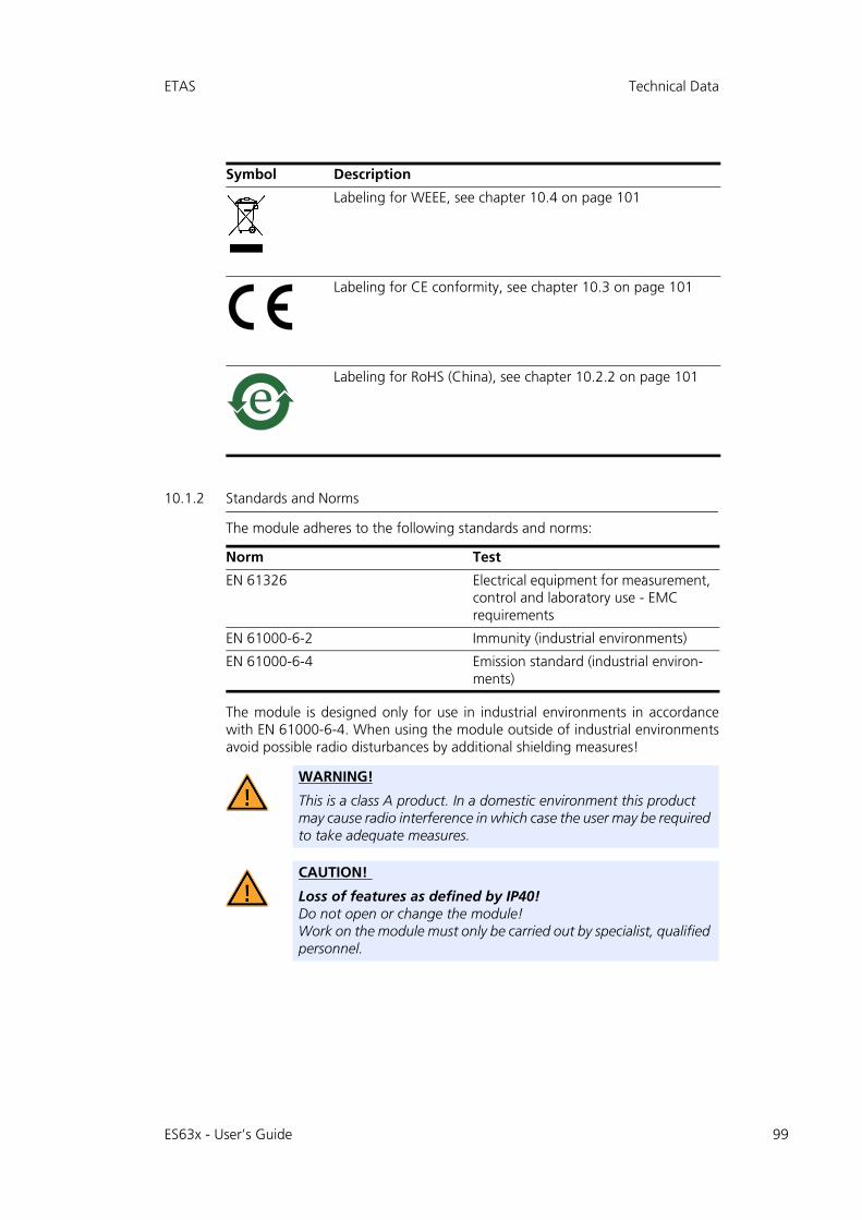
ETAS Technical Data
10.1.2 Standards and Norms
The module adheres to the following standards and norms:
The module is designed only for use in industrial environments in accordancewith EN 61000-6-4. When using the module outside of industrial environmentsavoid possible radio disturbances by additional shielding measures!
Labeling for WEEE, see chapter 10.4 on page 101
Labeling for CE conformity, see chapter 10.3 on page 101
Labeling for RoHS (China), see chapter 10.2.2 on page 101
Norm Test
EN 61326 Electrical equipment for measurement, control and laboratory use - EMC requirements
EN 61000-6-2 Immunity (industrial environments)
EN 61000-6-4 Emission standard (industrial environ-ments)
WARNING!
This is a class A product. In a domestic environment this product may cause radio interference in which case the user may be required to take adequate measures.
CAUTION!
Loss of features as defined by IP40!Do not open or change the module!Work on the module must only be carried out by specialist, qualified personnel.
Symbol Description
ES63x - User’s Guide 99
100
Technical Data ETAS
10.1.3 Environmental Conditions
10.1.4 Maintenance the Product
Do not open or change the module! Works on the module housing may be exe-cuted only by qualified technical personnel. Send defect modules to ETAS.
10.1.5 Cleaning the product
We recommend to clean the product with a dry cloth.
10.1.6 Mechanical Data
Operating temperature range -40 °C to +70 °C/ -40 °F to +158 °F
Storage temperature range(module without packaging)
-40 °C to +85 °C / -40 °F to +185 °F
Relative humidity (non-condensing) 0 to 95%
Implementation altitude max. 5000 m/ 16400 ft
Protection class IP40
Degree of pollution 2
Note
The module is suited for use in interiors, in the passenger compartment or in the luggage compartment of vehicles.
Dimensions (H x W x D) 73 mm x 128 mm x 174 mm /2.9 in x 5 in x 6.8 in
Weight ES630.1: 905 g / 2.0 lb
ES631.1: 1055 g / 2.33 lb
ES635.1: 920 g / 2.03 lb
ES636.1: 1085 g / 2.39 lb
ES63x - User’s Guide
ETAS Technical Data
10.2 RoHS Conformity
10.2.1 European Union
The EU Directive 2002/95/EU limits the use of certain dangerous materials forelectrical and electronic devices (RoHS conformity).
ETAS confirms that the product corresponds to this directive which is applicablein the European Union.
10.2.2 China
ETAS confirms that the product meets the product-specific applicable guidelinesof the China RoHS (Management Methods for Controlling Pollution Caused byElectronic Information Products Regulation) applicable in China with the ChinaRoHS marking affixed to the product or its packaging.
10.3 CE Labeling
ETAS confirms that the product meets the product-specific, applicable Europeanguideline with a CE label on the product or its packaging. CE conformity decla-ration for the product is available upon request.
10.4 Taking the Product Back and Recycling
The European Union has passed a directive called Waste Electrical and ElectronicEquipment, or WEEE for short, to ensure that systems are setup throughout theEU for the collection, treating and recycling of electronic waste.
This ensures that the devices are recycled in a resource-saving way representingno danger to health or the environment.
Fig. 10-1 WEEE Symbol
The WEEE symbol (see Fig. 10-1 on page 101) on the product or its packagingshows that the product must not be disposed of as residual garbage.
The user is obliged to collect the old devices separately and return them to theWEEE take-back system for recycling.
The WEEE directive concerns all ETAS devices but not external cables or batteries.
For more information on the ETAS GmbH Recycling Program, contact the ETASsales and service locations (see chapter 16 on page 197).
ES63x - User’s Guide 101
102
Technical Data ETAS
10.5 Declarable Substances
European Union
Some products from ETAS GmbH (e.g. modules, boards, cables) use componentswith substances that are subject to declaration in accordance with the REACHregulation (EU) no.1907/2006. Detailed information is located in the ETAS download center in the customerinformation "REACH Declaration" (www.etas.com/Reach). This information iscontinuously being updated.
10.6 Use of Open Source software
The product uses Open Source Software (OSS). This software is installed in theproduct at the time of delivery and does not have to be installed or updated bythe user. Reference shall be made to the use of the software in order to fulfill OSSlicensing terms. Additional information is available in the document "OSS Attri-butions List" at the ETAS website www.etas.com.
10.7 System Requirements
10.7.1 Hardware
Operation of the module requires a power supply voltage of 7 V to 29 V DC.
PC with one Ethernet interface
A PC with one open Ethernet interface (1 Gbit/s or 100 Mbit/s, full duplex) withRJ-45 connection is required. Ethernet interfaces that are implemented with anadditional network card in the PC must feature a 32-bit data bus.
Requirement to ensure successful initialization of the module
To deactivate the power saving mode:
Choose in System Control Center / Device Manager / Network Adapter the usednetwork adapter by double-click. Deactivate the "Allow the computer to turn offthis device to save power" option in the "Power Management" register. Confirmyour configuration.
The manufacturers of network adapter have different names for this function.
Example:
• “Link down Power saving”
• "Allow the computer to turn off this device to save power".
Note
It is imperative you disable the function which automatically switches to power-saving mode on your PC network adapter when there is no data traffic on the Ethernet interface!
ES63x - User’s Guide
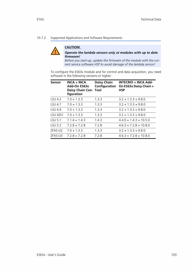
ETAS Technical Data
10.7.2 Supported Applications and Software Requirements
To configure the ES63x module and for control and data acquisition, you needsoftware in the following versions or higher:
CAUTION!
Operate the lambda sensors only at modules with up to date firmware!Before you start-up, update the firmware of the module with the cur-rent service software HSP to avoid damage of the lambda sensor!
Sensor INCA + INCA Add-On ES63x Daisy Chain Con-figuration
Daisy Chain Configuration Tool
INTECRIO + INCA Add-On ES63x Daisy Chain + HSP
LSU 4.2 7.0 + 1.3.3 1.3.3 3.2 + 1.3.3 + 9.8.0
LSU 4.7 7.0 + 1.3.3 1.3.3 3.2 + 1.3.3 + 9.8.0
LSU 4.9 7.0 + 1.3.3 1.3.3 3.2 + 1.3.3 + 9.8.0
LSU ADV 7.0 + 1.3.3 1.3.3 3.2 + 1.3.3 + 9.8.0
LSU 5.1 7.1.4 + 1.4.3 1.4.3 4.4.0 + 1.4.3 + 10.5.0
LSU 5.2 7.2.8 + 7.2.8 7.2.8 4.6.3 + 7.2.8 + 10.8.0
ZFAS-U2 7.0 + 1.3.3 1.3.3 3.2 + 1.3.3 + 9.8.0
ZFAS-U3 7.2.8 + 7.2.8 7.2.8 4.6.3 + 7.2.8 + 10.8.0
ES63x - User’s Guide 103

104
Technical Data ETAS
10.8 Electrical Data
10.8.1 Measurement Category
The module is designed for measuring category CAT I.
10.8.2 Measurement Accuracy
10.8.3 Host Interface (Ethernet)
Note
ETAS guarantees measurement accuracy of the module for one year. Please use our calibration service (see section 5.8 on page 55)!
Note
Unless otherwise specified, all data applies at 25 °C.
Socket 100Base-T Ethernet; 100 Mbit/s,Full Duplex necessary
PC Card 32 bit
Protocol XCP on UDP/IP
IP address Dynamic via INCA, INTECRIO orin stand-alone operation with ES63x Daisy Chain Configuration Tool from ES6xx_DRV_SW(Default: 192.168.40.44)
Note
To ensure successful initialization of the network card of your PC, refer to chap-ter 10.7.1 on page 102.
ES63x - User’s Guide
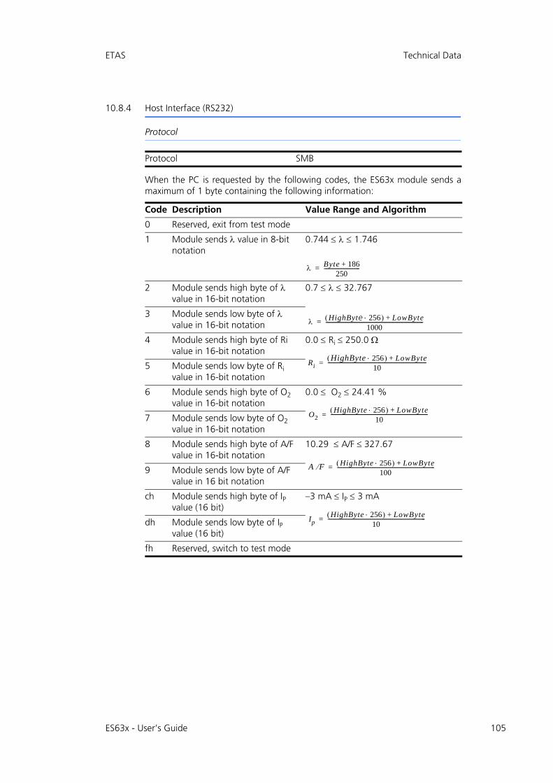
ETAS Technical Data
10.8.4 Host Interface (RS232)
Protocol
When the PC is requested by the following codes, the ES63x module sends amaximum of 1 byte containing the following information:
Protocol SMB
Code Description Value Range and Algorithm
0 Reserved, exit from test mode
1 Module sends value in 8-bit notation
0.744 1.746
2 Module sends high byte of value in 16-bit notation
0.7 32.767
3 Module sends low byte of value in 16-bit notation
4 Module sends high byte of Ri value in 16-bit notation
0.0 Ri 250.0
5 Module sends low byte of Ri value in 16-bit notation
6 Module sends high byte of O2 value in 16-bit notation
0.0 O2 24.41 %
7 Module sends low byte of O2 value in 16-bit notation
8 Module sends high byte of A/F value in 16-bit notation
10.29 A/F 327.67
9 Module sends low byte of A/F value in 16 bit notation
ch Module sends high byte of IP value (16 bit)
–3 mA IP 3 mA
dh Module sends low byte of IP value (16 bit)
fh Reserved, switch to test mode
Byte 186+250
---------------------------=
HighByte 256 LowByte+1000
--------------------------------------------------------------------------=
RiHighByte 256 LowByte+
10---------------------------------------------------------------------------=
O2HighByte 256 LowByte+
10--------------------------------------------------------------------------=
A F HighByte 256 LowByte+100
--------------------------------------------------------------------------=
IpHighByte 256 LowByte+
10--------------------------------------------------------------------------=
ES63x - User’s Guide 105
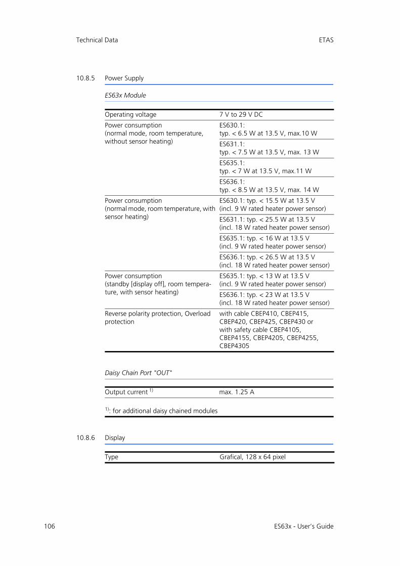
106
Technical Data ETAS
10.8.5 Power Supply
ES63x Module
Daisy Chain Port "OUT"
10.8.6 Display
Operating voltage 7 V to 29 V DC
Power consumption(normal mode, room temperature, without sensor heating)
ES630.1:typ. < 6.5 W at 13.5 V, max.10 W
ES631.1:typ. < 7.5 W at 13.5 V, max. 13 W
ES635.1:typ. < 7 W at 13.5 V, max.11 W
ES636.1:typ. < 8.5 W at 13.5 V, max. 14 W
Power consumption(normal mode, room temperature, with sensor heating)
ES630.1: typ. < 15.5 W at 13.5 V(incl. 9 W rated heater power sensor)
ES631.1: typ. < 25.5 W at 13.5 V(incl. 18 W rated heater power sensor)
ES635.1: typ. < 16 W at 13.5 V(incl. 9 W rated heater power sensor)
ES636.1: typ. < 26.5 W at 13.5 V(incl. 18 W rated heater power sensor)
Power consumption(standby [display off], room tempera-ture, with sensor heating)
ES635.1: typ. < 13 W at 13.5 V(incl. 9 W rated heater power sensor)
ES636.1: typ. < 23 W at 13.5 V(incl. 18 W rated heater power sensor)
Reverse polarity protection, Overload protection
with cable CBEP410, CBEP415, CBEP420, CBEP425, CBEP430 orwith safety cable CBEP4105, CBEP4155, CBEP4205, CBEP4255, CBEP4305
Output current 1) max. 1.25 A
1): for additional daisy chained modules
Type Grafical, 128 x 64 pixel
ES63x - User’s Guide
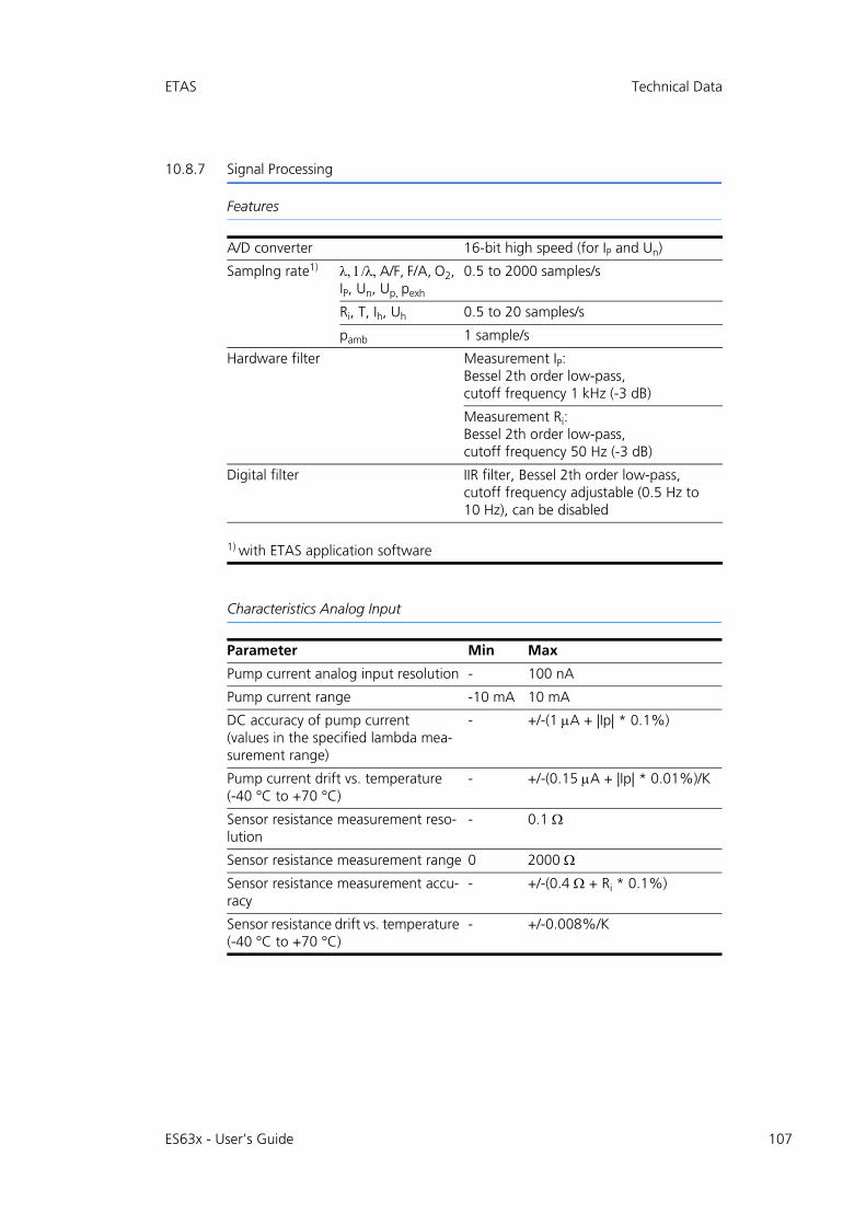
ETAS Technical Data
10.8.7 Signal Processing
Features
Characteristics Analog Input
A/D converter 16-bit high speed (for IP and Un)
Samplng rate1) A/F, F/A, O2, IP, Un, Up, pexh
0.5 to 2000 samples/s
Ri, T, Ih, Uh 0.5 to 20 samples/s
pamb 1 sample/s
Hardware filter Measurement IP:Bessel 2th order low-pass,cutoff frequency 1 kHz (-3 dB)
Measurement Ri:Bessel 2th order low-pass,cutoff frequency 50 Hz (-3 dB)
Digital filter IIR filter, Bessel 2th order low-pass,cutoff frequency adjustable (0.5 Hz to 10 Hz), can be disabled
1) with ETAS application software
Parameter Min Max
Pump current analog input resolution - 100 nA
Pump current range -10 mA 10 mA
DC accuracy of pump current(values in the specified lambda mea-surement range)
- +/-(1 A + |Ip| * 0.1%)
Pump current drift vs. temperature(-40 °C to +70 °C)
- +/-(0.15 A + |Ip| * 0.01%)/K
Sensor resistance measurement reso-lution
- 0.1
Sensor resistance measurement range 0 2000
Sensor resistance measurement accu-racy
- +/-(0.4 + Ri * 0.1%)
Sensor resistance drift vs. temperature (-40 °C to +70 °C)
- +/-0.008%/K
ES63x - User’s Guide 107

108
Technical Data ETAS
Measure Values and Measurement Ranges
All measure values are available simultaneously at the module (display) and in thecalibration software.
Symbol Measure Value Min Max Invalid Value
Unit
l Lambda 0.6 33.0 -0.01 -
A/F Air to fuel ratio 8.5 327.67 -0.1 -
O2 O2 concentration 0.0 25.0 -0.1 %
F/A Fuel to air ratio 0.004 0.12 -0.001 -
1/ Reciprocal Lambda 0.06 1.67 -0.001 -
Ip Pump current -10.0 10.0 -15.0 mA
Ri Sensor resistance 0.0 2000.0 -1.0
Uh Heater voltage 0.0 18.0 -1.0 V
Ih Heater current 0.0 10.0 -1.0 A
Un Nernst voltage 0.0 900.0 -10.0 mV
Up Pump voltage -4000.0 4000.0 -10000.0 mV
T Sensor temperature 500.0 1500.0 -1000 °C
pa Ambient pressure 600.0 1150 -1.0 hPa
pex Pressure from external pres-sure sensor (ES635.1 and ES636.1 only)
500.0 5000.0 -1.0 hPa
Fr Oxygen reservoir fill level (for LSU 5.1 only)
0 100 -1 %
Sta State/ operational state of the sensor
0 2 -1 -
ES63x - User’s Guide
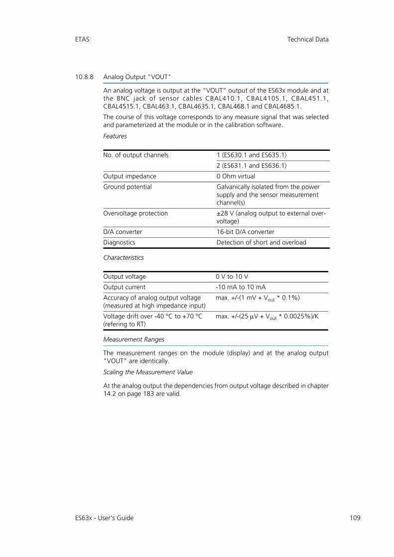
ETAS Technical Data
10.8.8 Analog Output "VOUT"
An analog voltage is output at the “VOUT” output of the ES63x module and atthe BNC jack of sensor cables CBAL410.1, CBAL4105.1, CBAL451.1,CBAL4515.1, CBAL463.1, CBAL4635.1, CBAL468.1 and CBAL4685.1.
The course of this voltage corresponds to any measure signal that was selectedand parameterized at the module or in the calibration software.
Features
Characteristics
Measurement Ranges
The measurement ranges on the module (display) and at the analog output"VOUT" are identically.
Scaling the Measurement Value
At the analog output the dependencies from output voltage described in chapter14.2 on page 183 are valid.
No. of output channels 1 (ES630.1 and ES635.1)
2 (ES631.1 and ES636.1)
Output impedance 0 Ohm virtual
Ground potential Galvanically isolated from the power supply and the sensor measurement channel(s)
Overvoltage protection ±28 V (analog output to external over-voltage)
D/A converter 16-bit D/A converter
Diagnostics Detection of short and overload
Output voltage 0 V to 10 V
Output current -10 mA to 10 mA
Accuracy of analog output voltage (measured at high impedance input)
max. +/-(1 mV + Vout * 0.1%)
Voltage drift over -40 °C to +70 °C(refering to RT)
max. +/-(25 V + Vout * 0.0025%)/K
ES63x - User’s Guide 109

110
Technical Data ETAS
10.8.9 EXTEN - External Signal
The state of the sensor heater control can be controlled with the EXTEN signal ifthe signal was selected in the calibration software and if the ES63x module is offor on standby.
The control possibilities of the states of the sensor heater control is shown insection 4.4.2 on page 38 dargestellt.
10.8.10 Sensor Port
Symbol Parameter Min Max Unit
VON_th Threshold value EXTEN - On - 9 V
VOFF_th Threshold value EXTEN - Off 6 - V
Channels 1, galvanically isolated from the power supply (ES630.1 and ES635.1)
2, galvanically isolated from the power supply (ES631.1 and ES636.1)
Power supply 9 V to 28 V
Power consumption (standby, sensor in still air, room temperature)
Typ. 9 W
Power consumption (standby, sensor in still air, room temperature)
Typ. 9 W (per measurement channel)
Overvoltage protection 28 V
Supported sensor types Robert Bosch LSU 4.2, LSU 4.7, LSU 4.9, LSU 5.1, LSU 5.2, LSU ADV-G
NTK ZFAS-U2, ZFAS-U3
Sensor detection Automatic detection via the sensor cable
Sensor connector On cable CBAL410 / CBAL4105:RB130fl, Code 1
On cable CBAL451 / CBAL4515 and CBAL452 / CBAL4525:RB150, Code 1
On cable CBAL463 / CBAL4635:Trapezoid plug, Code A7
On cable CBAL468 / CBAL4685:RB150, Code 2
On cable CBAL472 / CBAL4725:RB150, Code 1 NTK
ES63x - User’s Guide
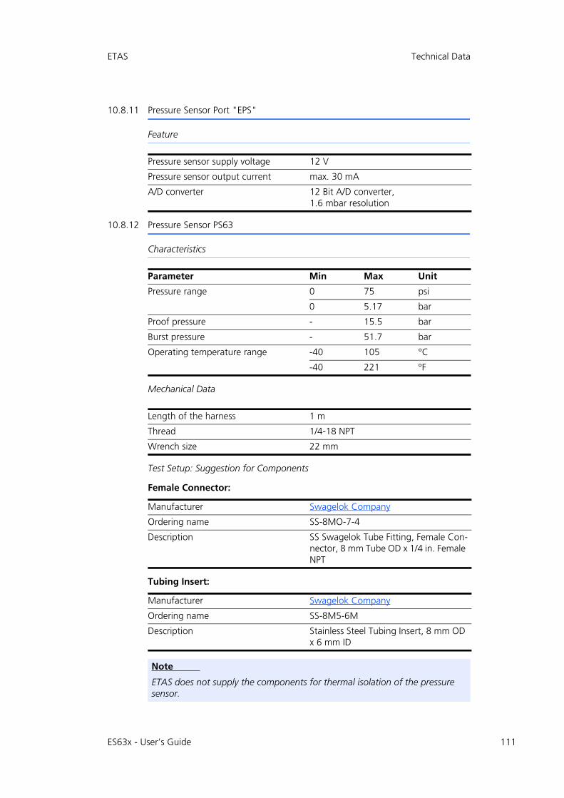
ETAS Technical Data
10.8.11 Pressure Sensor Port "EPS"
Feature
10.8.12 Pressure Sensor PS63
Characteristics
Mechanical Data
Test Setup: Suggestion for Components
Female Connector:
Tubing Insert:
Pressure sensor supply voltage 12 V
Pressure sensor output current max. 30 mA
A/D converter 12 Bit A/D converter,1.6 mbar resolution
Parameter Min Max Unit
Pressure range 0 75 psi
0 5.17 bar
Proof pressure - 15.5 bar
Burst pressure - 51.7 bar
Operating temperature range -40 105 °C
-40 221 °F
Length of the harness 1 m
Thread 1/4-18 NPT
Wrench size 22 mm
Manufacturer Swagelok Company
Ordering name SS-8MO-7-4
Description SS Swagelok Tube Fitting, Female Con-nector, 8 mm Tube OD x 1/4 in. Female NPT
Manufacturer Swagelok Company
Ordering name SS-8M5-6M
Description Stainless Steel Tubing Insert, 8 mm OD x 6 mm ID
Note
ETAS does not supply the components for thermal isolation of the pressure sensor.
ES63x - User’s Guide 111

112
Technical Data ETAS
10.9 Pin Assignment
10.9.1 “IN” Connector
Fig. 10-2 „IN“ Connecor
Note
All connectors are shown with a view of the front of the ES63x module. All shields are at case potential.
Pin Signal Meaning
1 UBatt Operating voltage
2 Ground Ground
3 RX- Received data, minus
4 TX- Send data, minus
5 RX+ Received data, plus
6 Ground Ground
7 UBatt Operating voltage
8 TX+ Send data, plus
NT
U
ES63x - User’s Guide
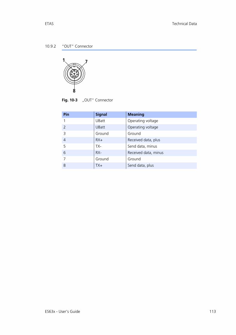
ETAS Technical Data
10.9.2 “OUT” Connector
Fig. 10-3 „OUT“ Connector
Pin Signal Meaning
1 UBatt Operating voltage
2 UBatt Operating voltage
3 Ground Ground
4 RX+ Received data, plus
5 TX- Send data, minus
6 RX- Received data, minus
7 Ground Ground
8 TX+ Send data, plus
N T
U
ES63x - User’s Guide 113
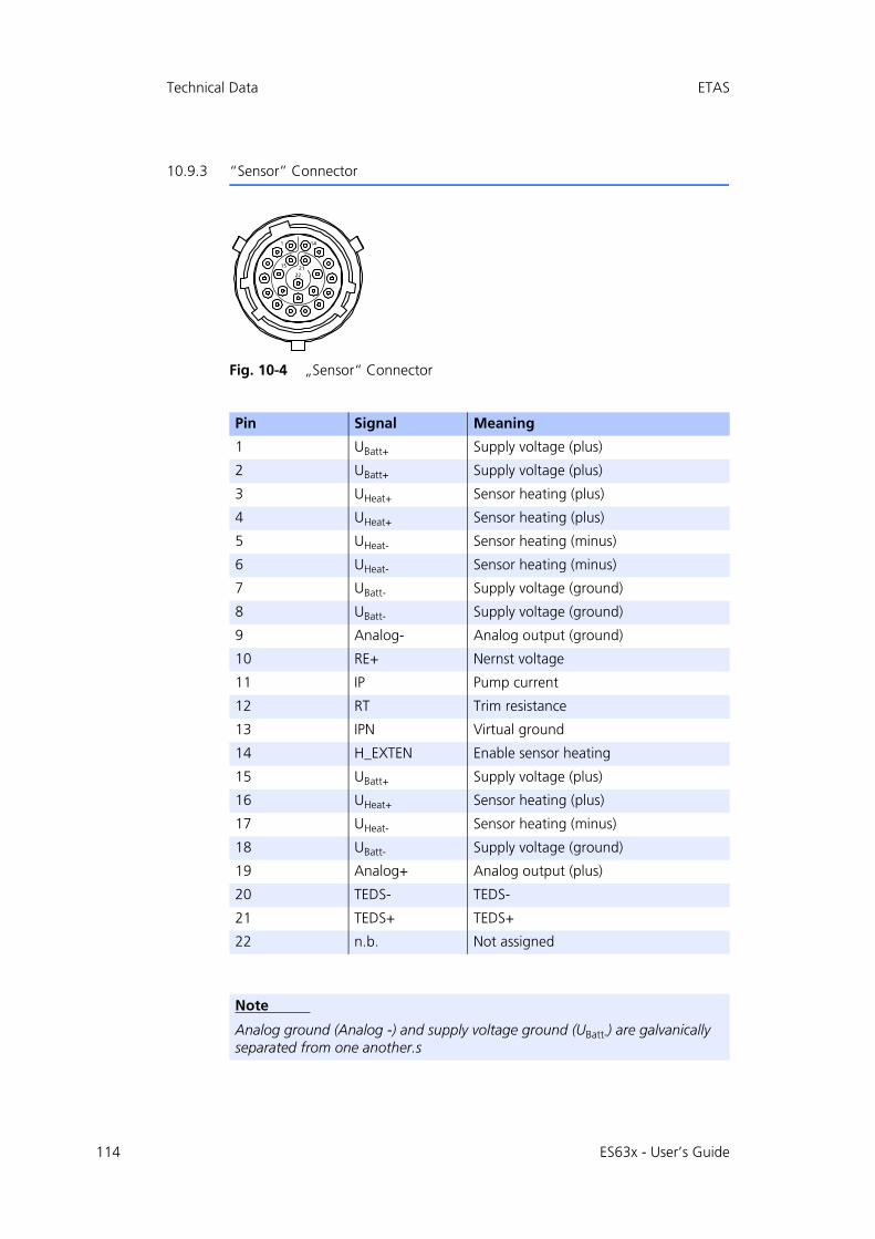
114
Technical Data ETAS
10.9.3 “Sensor” Connector
Fig. 10-4 „Sensor“ Connector
Pin Signal Meaning
1 UBatt+ Supply voltage (plus)
2 UBatt+ Supply voltage (plus)
3 UHeat+ Sensor heating (plus)
4 UHeat+ Sensor heating (plus)
5 UHeat- Sensor heating (minus)
6 UHeat- Sensor heating (minus)
7 UBatt- Supply voltage (ground)
8 UBatt- Supply voltage (ground)
9 Analog- Analog output (ground)
10 RE+ Nernst voltage
11 IP Pump current
12 RT Trim resistance
13 IPN Virtual ground
14 H_EXTEN Enable sensor heating
15 UBatt+ Supply voltage (plus)
16 UHeat+ Sensor heating (plus)
17 UHeat- Sensor heating (minus)
18 UBatt- Supply voltage (ground)
19 Analog+ Analog output (plus)
20 TEDS- TEDS-
21 TEDS+ TEDS+
22 n.b. Not assigned
Note
Analog ground (Analog -) and supply voltage ground (UBatt-) are galvanically separated from one another.s
ES63x - User’s Guide
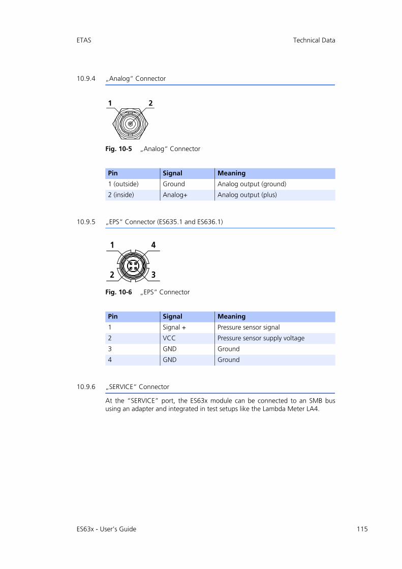
ETAS Technical Data
10.9.4 „Analog“ Connector
Fig. 10-5 „Analog“ Connector
10.9.5 „EPS“ Connector (ES635.1 and ES636.1)
Fig. 10-6 „EPS“ Connector
10.9.6 „SERVICE“ Connector
At the “SERVICE” port, the ES63x module can be connected to an SMB bususing an adapter and integrated in test setups like the Lambda Meter LA4.
Pin Signal Meaning
1 (outside) Ground Analog output (ground)
2 (inside) Analog+ Analog output (plus)
Pin Signal Meaning
1 Signal + Pressure sensor signal
2 VCC Pressure sensor supply voltage
3 GND Ground
4 GND Ground
ON
QN
PO
ES63x - User’s Guide 115
ES63x - User’s Guide116
Cables and Accessories ETAS
11 Cables and Accessories
This chapter contains information on the following topics:
• "Power Supply Cable" on page 117
• "Combined Ethernet and Power Supply Cable" on page 119
• "Ethernet Cable" on page 125
• "SMB Cable" on page 127
• "Sensor Cables" on page 129
• "Pressure Sensor and Accessories" on page 155
• "Protective Caps" on page 156
The “Cables and Accessories” chapter contains an overview of the availablecables and accessories.
Note
Only use ETAS cables at the interfaces of the module. Adhere to the maximum cable lengths!
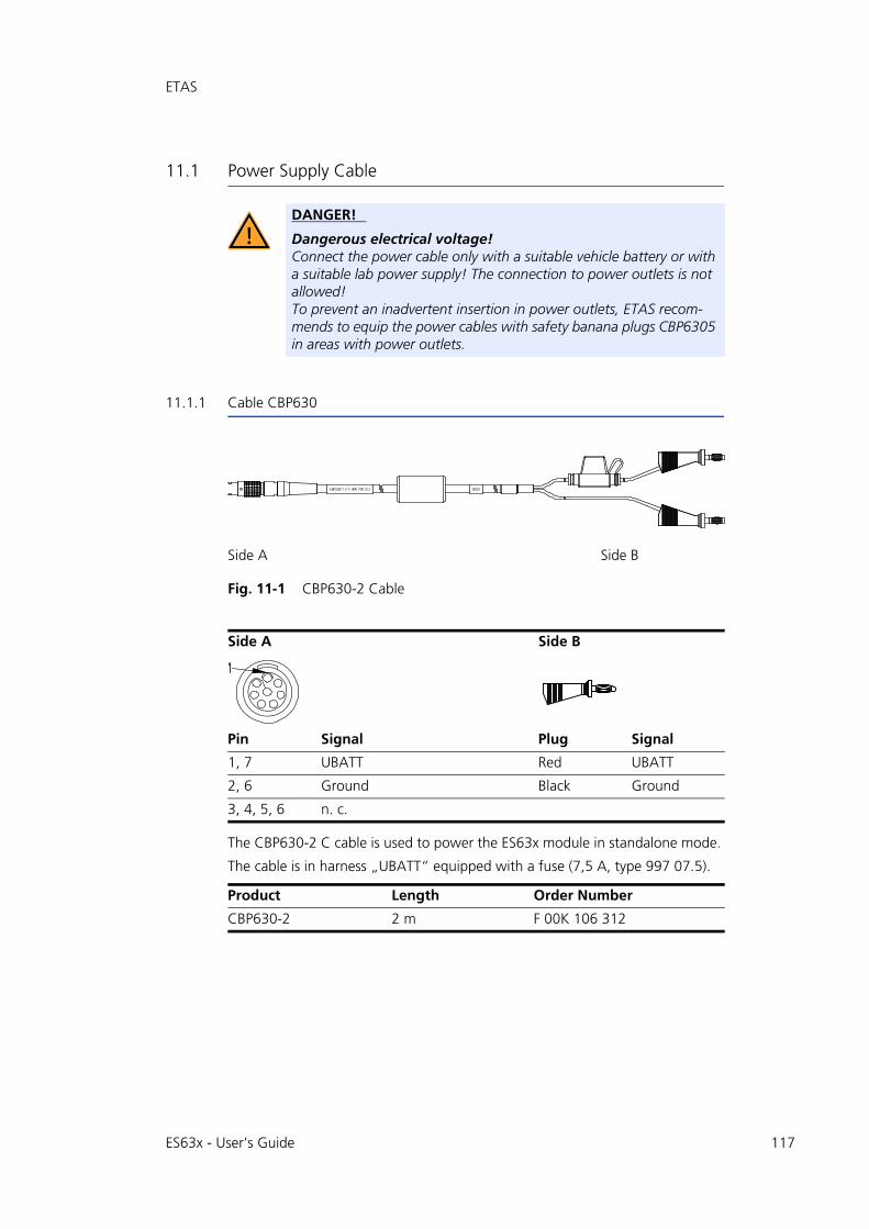
ETAS
11.1 Power Supply Cable
11.1.1 Cable CBP630
Fig. 11-1 CBP630-2 Cable
The CBP630-2 C cable is used to power the ES63x module in standalone mode.
The cable is in harness „UBATT“ equipped with a fuse (7,5 A, type 997 07.5).
DANGER!
Dangerous electrical voltage!Connect the power cable only with a suitable vehicle battery or with a suitable lab power supply! The connection to power outlets is not allowed!To prevent an inadvertent insertion in power outlets, ETAS recom-mends to equip the power cables with safety banana plugs CBP6305 in areas with power outlets.
Side A Side B
Side A Side B
Pin Signal Plug Signal
1, 7 UBATT Red UBATT
2, 6 Ground Black Ground
3, 4, 5, 6 n. c.
Product Length Order Number
CBP630-2 2 m F 00K 106 312
ES63x - User’s Guide 117
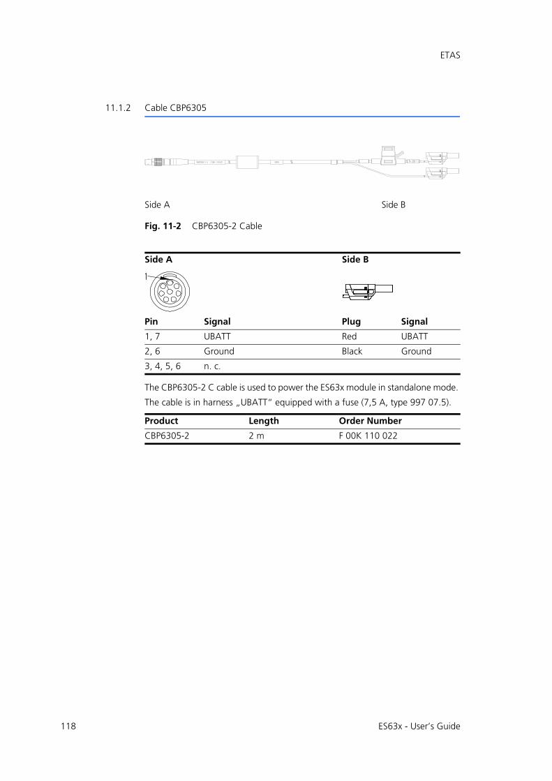
118
ETAS
11.1.2 Cable CBP6305
Fig. 11-2 CBP6305-2 Cable
The CBP6305-2 C cable is used to power the ES63x module in standalone mode.
The cable is in harness „UBATT“ equipped with a fuse (7,5 A, type 997 07.5).
Side A Side B
Side A Side B
Pin Signal Plug Signal
1, 7 UBATT Red UBATT
2, 6 Ground Black Ground
3, 4, 5, 6 n. c.
Product Length Order Number
CBP6305-2 2 m F 00K 110 022
ES63x - User’s Guide
ETAS
11.2 Combined Ethernet and Power Supply Cable
This chapter contains information on the following cables:
• "CBEP410.1 Cable" on page 120
• "CBEP4105.1 Cable" on page 120
• "CBEP415.1 Cable" on page 121
• "CBEP4155.1 Cable" on page 121
• "CBEP420.1 Cable" on page 122
• "CBEP4205.1 Cable" on page 122
• "CBEP425.1 Cable" on page 123
• "CBEP4255.1 Cable" on page 123
• "CBEP430.1 Cable" on page 124
• "CBEP4305.1 Cable" on page 124
11.2.1 Overview
You can use combined ethernet and power supply cables with standard bananaplugs or with safety banana plugs:
DANGER!
Dangerous electrical voltage!Connect the power cable only with a suitable vehicle battery or with a suitable lab power supply! The connection to power outlets is not allowed!To prevent an inadvertent insertion in power outlets, ETAS recom-mends to equip the combined ethernet and power supply cables with safety banana plugs in areas with power outlets.
Cables with standard banana plugs Cables with safety banana plugs
CBEP410.1 CBEP4105.1
CBEP415.1 CBEP4155.1
CBEP420.1 CBEP4205.1
CBEP425.1 CBEP4255.1
CBEP430.1 CBEP4305.1
ES63x - User’s Guide 119
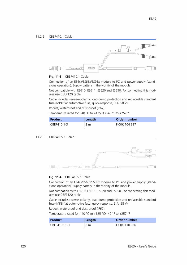
120
ETAS
11.2.2 CBEP410.1 Cable
Fig. 11-3 CBEP410.1 Cable
Connection of an ES4xx/ES63x/ES93x module to PC and power supply (stand-alone operation). Supply battery in the vicinity of the module.
Not compatible with ES610, ES611, ES620 and ES650. For connecting this mod-ules use CBEP120 cable.
Cable includes reverse-polarity, load-dump protection and replaceable standardfuse (MINI flat automotive fuse, quick-response, 3 A, 58 V).
Robust, waterproof and dust-proof (IP67).
Temperature rated for: -40 °C to +125 °C/ -40 °F to +257 °F
11.2.3 CBEP4105.1 Cable
Fig. 11-4 CBEP4105.1 Cable
Connection of an ES4xx/ES63x/ES93x module to PC and power supply (stand-alone operation). Supply battery in the vicinity of the module.
Not compatible with ES610, ES611, ES620 and ES650. For connecting this mod-ules use CBEP120 cable.
Cable includes reverse-polarity, load-dump protection and replaceable standardfuse (MINI flat automotive fuse, quick-response, 3 A, 58 V).
Robust, waterproof and dust-proof (IP67).
Temperature rated for: -40 °C to +125 °C/ -40 °F to +257 °F
Product Length Order number
CBEP410.1-3 3 m F 00K 104 927
Product Length Order number
CBEP4105.1-3 3 m F 00K 110 026
ES63x - User’s Guide
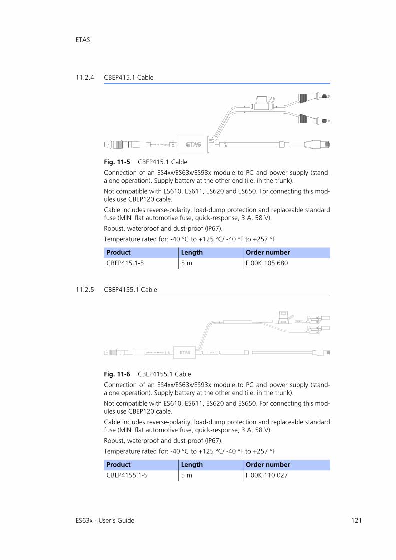
ETAS
11.2.4 CBEP415.1 Cable
Fig. 11-5 CBEP415.1 Cable
Connection of an ES4xx/ES63x/ES93x module to PC and power supply (stand-alone operation). Supply battery at the other end (i.e. in the trunk).
Not compatible with ES610, ES611, ES620 and ES650. For connecting this mod-ules use CBEP120 cable.
Cable includes reverse-polarity, load-dump protection and replaceable standardfuse (MINI flat automotive fuse, quick-response, 3 A, 58 V).
Robust, waterproof and dust-proof (IP67).
Temperature rated for: -40 °C to +125 °C/ -40 °F to +257 °F
11.2.5 CBEP4155.1 Cable
Fig. 11-6 CBEP4155.1 Cable
Connection of an ES4xx/ES63x/ES93x module to PC and power supply (stand-alone operation). Supply battery at the other end (i.e. in the trunk).
Not compatible with ES610, ES611, ES620 and ES650. For connecting this mod-ules use CBEP120 cable.
Cable includes reverse-polarity, load-dump protection and replaceable standardfuse (MINI flat automotive fuse, quick-response, 3 A, 58 V).
Robust, waterproof and dust-proof (IP67).
Temperature rated for: -40 °C to +125 °C/ -40 °F to +257 °F
Product Length Order number
CBEP415.1-5 5 m F 00K 105 680
Product Length Order number
CBEP4155.1-5 5 m F 00K 110 027
ES63x - User’s Guide 121

122
ETAS
11.2.6 CBEP420.1 Cable
Fig. 11-7 CBEP420.1 Cable
Ethernet and voltage supply connection of an ES4xx/ES63x/ES93x measurementmodule with an ES600 network module or ES592/ES593-D/ES595 interfacemodule (if the current consumption of the connected ES4xx/ES63x chain exceeds2.5 A), an ES1135 simulation/system controller card or an ES720 Drive Recorder.
Not compatible with ES610, ES611, ES620 and ES650. For connecting this mod-ules use CBEP120 cable.
Cable includes reverse-polarity, load-dump protection and replaceable standardfuse (MINI flat automotive fuse, quick-response, 3 A, 58 V).
Robust, waterproof and dust-proof (IP67).
Temperature rated for: -40 °C to +125 °C/ -40 °F to +257 °F
11.2.7 CBEP4205.1 Cable
Fig. 11-8 CBEP4205.1 Cable
Ethernet and voltage supply connection of an ES4xx/ES63x/ES93x measurementmodule with an ES600 network module or ES592/ES593-D/ES595 interfacemodule (if the current consumption of the connected ES4xx/ES63x chain exceeds2.5 A), an ES1135 simulation/system controller card or an ES720 Drive Recorder.
Not compatible with ES610, ES611, ES620 and ES650. For connecting this mod-ules use CBEP120 cable.
Cable includes reverse-polarity, load-dump protection and replaceable standardfuse (MINI flat automotive fuse, quick-response, 3 A, 58 V).
Robust, waterproof and dust-proof (IP67).
Temperature rated for: -40 °C to +125 °C/ -40 °F to +257 °F
Product Length Order number
CBEP420.1-3 3 m F 00K 105 292
Product Length Order number
CBEP4205.1-3 3 m F 00K 110 041
ES63x - User’s Guide

ETAS
11.2.8 CBEP425.1 Cable
Fig. 11-9 CBEP425.1 Cable
Ethernet and voltage supply connection of an ES4xx/ES63x/ES93x measurementmodule with an ES600 network module or ES592/ES593-D/ES595 interfacemodule (if the current consumption of the connected ES4xx/ES63x/ES93x chainexceeds 2.5 A), an ES1135 simulation/system controller card or an ES720 DriveRecorder.
Cable includes reverse-polarity, load-dump protection and replaceable standardfuse (MINI flat automotive fuse, quick-response, 3 A, 58 V).
Robust, waterproof and dust-proof (IP67).
Temperature rated for: -40 °C to +125 °C/ -40 °F to +257 °F
11.2.9 CBEP4255.1 Cable
Fig. 11-10 CBEP4255.1 Cable
Ethernet and voltage supply connection of an ES4xx/ES63x/ES93x measurementmodule with an ES600 network module or ES592/ES593-D/ES595 interfacemodule (if the current consumption of the connected ES4xx/ES63x/ES93x chainexceeds 2.5 A), an ES1135 simulation/system controller card or an ES720 DriveRecorder.
Cable includes reverse-polarity, load-dump protection and replaceable standardfuse (MINI flat automotive fuse, quick-response, 3 A, 58 V).
Robust, waterproof and dust-proof (IP67).
Temperature rated for: -40 °C to +125 °C/ -40 °F to +257 °F
Product Length Order number
CBEP425.1-3 3 m F 00K 105 972
Product Length Order number
CBEP4255.1-3 3 m F 00K 110 029
ES63x - User’s Guide 123

124
ETAS
11.2.10 CBEP430.1 Cable
Fig. 11-11 CBEP430.1 Cable
To chain ES4xx/ES63x/ES93x modules and connect an ES4xx/ES63x/ES93x chainto an ES910.3 Rapid Prototyping module. Additional connection to the powersupply to compensate for voltage losses in long chains.
Not compatible with ES59x, ES6xx, ES11xx. For connecting this modules useCBE130 or CBE140 cable.
Cable includes reverse-polarity, load-dump protection and replaceable standardfuse (MINI flat automotive fuse, quick-response, 3 A, 58 V).
Robust, waterproof and dust-proof (IP67).
Temperature rated for: -40 °C to +125 °C/ -40 °F to +257 °F
11.2.11 CBEP4305.1 Cable
Fig. 11-12 CBEP4305.1 Cable
To chain ES4xx/ES63x/ES93x modules and connect an ES4xx/ES63x/ES93x chainto an ES910.3 Rapid Prototyping module. Additional connection to the powersupply to compensate for voltage losses in long chains.
Not compatible with ES59x, ES6xx, ES11xx. For connecting this modules useCBE130 or CBE140 cable.
Cable includes reverse-polarity, load-dump protection and replaceable standardfuse (MINI flat automotive fuse, quick-response, 3 A, 58 V).
Robust, waterproof and dust-proof (IP67).
Temperature rated for: -40 °C to +125 °C/ -40 °F to +257 °F
Product Length Order number
CBEP430.1-0m5 0.5 m F 00K 104 928
Product Length Order number
CBEP4305.1-0m5 0.5 m F 00K 110 030
ES63x - User’s Guide

ETAS
11.3 Ethernet Cable
This chapter contains information on the following cables:
• "CBE400.2 Cable" on page 125
• "CBE401.1 Cable" on page 125
• "CBE430.1 Cable" on page 126
• "CBE431.1 Cable" on page 126
• "CBEX400.1 Cable" on page 126
11.3.1 CBE400.2 Cable
Fig. 11-13 CBE400.2 Cable
Ethernet and voltage supply connection of an ES4xx/ES63x/ES93x measuringmodule at an ES600 network module or at an ES592/ES593-D/ES595 interfacemodule.
Cable includes reverse-polarity, load-dump protection and replaceable standardfuse (MINI flat automotive fuse, quick-response, 3 A, 58 V).
Robust, waterproof and dust-proof (IP67).
Temperature rated for: -40 °C to +125 °C/ -40 °F to +257 °F
11.3.2 CBE401.1 Cable
Fig. 11-14 CBE401.1 Cable
Highly flexible Ethernet and voltage supply connection of an ES4xx/ES63x/ES93xmeasuring module at an ES600 network module or at an ES592/ES593-D/ES595interface module.
Cable includes reverse-polarity, load-dump protection and replaceable standardfuse (MINI flat automotive fuse, quick-response, 3 A, 58 V).
Robust, waterproof and dust-proof (IP67).
Temperature rated for: -40 °C to +125 °C/ -40 °F to +257 °F
Product Length Order number
CBE400.2-3 3 m F 00K 104 920
Product Length Order number
CBE401.1-0m5 0.5 m F 00K 106 128
ES63x - User’s Guide 125
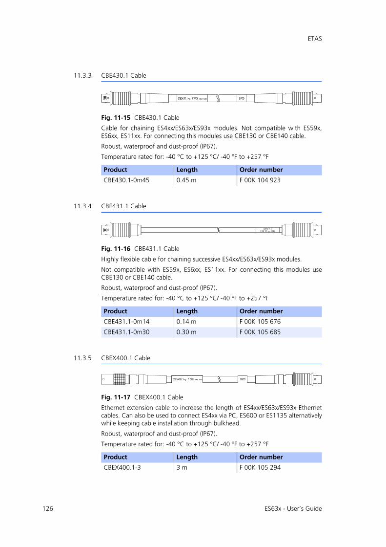
126
ETAS
11.3.3 CBE430.1 Cable
Fig. 11-15 CBE430.1 Cable
Cable for chaining ES4xx/ES63x/ES93x modules. Not compatible with ES59x,ES6xx, ES11xx. For connecting this modules use CBE130 or CBE140 cable.
Robust, waterproof and dust-proof (IP67).
Temperature rated for: -40 °C to +125 °C/ -40 °F to +257 °F
11.3.4 CBE431.1 Cable
Fig. 11-16 CBE431.1 Cable
Highly flexible cable for chaining successive ES4xx/ES63x/ES93x modules.
Not compatible with ES59x, ES6xx, ES11xx. For connecting this modules useCBE130 or CBE140 cable.
Robust, waterproof and dust-proof (IP67).
Temperature rated for: -40 °C to +125 °C/ -40 °F to +257 °F
11.3.5 CBEX400.1 Cable
Fig. 11-17 CBEX400.1 Cable
Ethernet extension cable to increase the length of ES4xx/ES63x/ES93x Ethernetcables. Can also be used to connect ES4xx via PC, ES600 or ES1135 alternativelywhile keeping cable installation through bulkhead.
Robust, waterproof and dust-proof (IP67).
Temperature rated for: -40 °C to +125 °C/ -40 °F to +257 °F
Product Length Order number
CBE430.1-0m45 0.45 m F 00K 104 923
Product Length Order number
CBE431.1-0m14 0.14 m F 00K 105 676
CBE431.1-0m30 0.30 m F 00K 105 685
Product Length Order number
CBEX400.1-3 3 m F 00K 105 294
ES63x - User’s Guide
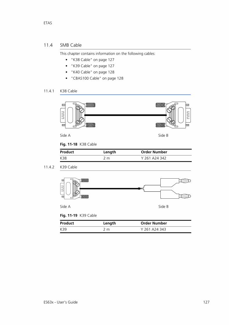
ETAS
11.4 SMB Cable
This chapter contains information on the following cables:
• "K38 Cable" on page 127
• "K39 Cable" on page 127
• "K40 Cable" on page 128
• "CBAS100 Cable" on page 128
11.4.1 K38 Cable
Fig. 11-18 K38 Cable
11.4.2 K39 Cable
Fig. 11-19 K39 Cable
Side A Side B
Product Length Order Number
K38 2 m Y 261 A24 342
Side A Side B
Product Length Order Number
K39 2 m Y 261 A24 343
ES63x - User’s Guide 127
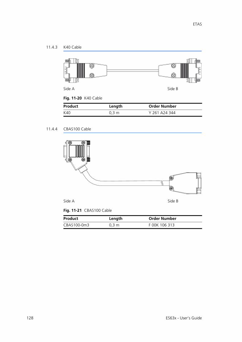
128
ETAS
11.4.3 K40 Cable
Fig. 11-20 K40 Cable
11.4.4 CBAS100 Cable
Fig. 11-21 CBAS100 Cable
Side A Side B
Product Length Order Number
K40 0,3 m Y 261 A24 344
Side A Side B
Product Length Order Number
CBAS100-0m3 0,3 m F 00K 106 313
ES63x - User’s Guide
ETAS
11.5 Sensor Cables
This chapter contains information on the following topics:
• "Lambda Sensors and associated Cables" on page 130
• "CBAL410.1 Cable" on page 131
• "CBAL4105.1 Cable" on page 133
• "CBAL451.1 Cable" on page 135
• "CBAL4515.1 Cable" on page 137
• "CBAL452.1 Cable" on page 139
• "CBAL4525.1 Cable" on page 141
• "CBAL463.1 Cable" on page 143
• "CBAL4635.1 Cable" on page 145
• "CBAL468.1 Cable" on page 147
• "CBAL4685.1 Cable" on page 149
• "CBAL472.1 Cable" on page 151
• "CBAL4725.1 Cable" on page 153
ES63x - User’s Guide 129
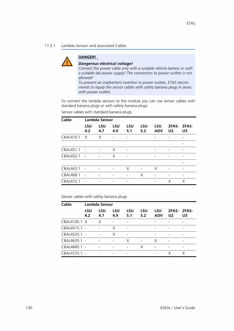
130
ETAS
11.5.1 Lambda Sensors and associated Cables
To connect the lambda sensors to the module you can use sensor cables withstandard banana plugs or with safety banana plugs:
Sensor cables with standard banana plugs
Sensor cables with safety banana plugs
DANGER!
Dangerous electrical voltage!Connect the power cable only with a suitable vehicle battery or with a suitable lab power supply! The connection to power outlets is not allowed!To prevent an inadvertent insertion in power outlets, ETAS recom-mends to equip the sensor cables with safety banana plugs in areas with power outlets.
Cable Lambda Sensor
LSU 4.2
LSU 4.7
LSU 4.9
LSU 5.1
LSU 5.2
LSU ADV
ZFAS-U2
ZFAS-U3
CBAL410.1 X X - - - - -
-
CBAL451.1 - - X - - - -
CBAL452.1 - - X - - - -
-
CBAL463.1 - - - X - X - -
CBAL468.1 - - - - X - - -
CBAL472.1 - - - - - X X
Cable Lambda Sensor
LSU 4.2
LSU 4.7
LSU 4.9
LSU 5.1
LSU 5.2
LSU ADV
ZFAS-U2
ZFAS-U3
CBAL4105.1 X X - - - - -
CBAL4515.1 - - X - - - -
CBAL4525.1 - - X - - - -
CBAL4635.1 - - - X - X - -
CBAL4685.1 - - - - X - - -
CBAL4725.1 - - - - - X X
ES63x - User’s Guide

ETAS
11.5.2 CBAL410.1 Cable
Fig. 11-22 CBAL410.1 Cable
Usage
Cable for Bosch Lambda Sensors LSU4.2 and LSU4.7 (Code 1)
Cable Plugs
PlugFig. 11-22
Comment
A RB130fl plug (Code 1) for the lambda sensor
B MC lamella connector for the external supply of the sensor heating (with inverse-polarity protection, overvoltage protection and cur-rent limitation)
Red connector = plus, black connector = minus
C BNC socket for analog output signals
D Input for powering on the heating for the sensor heating when the module is on “Standby”Sensor heating on: +9 V to +28 V
On delivery, the end of the cable is fixed as a loop in the shrinkage tube of the sensor cable. This must be pulled out to use the cable.
A
B
C
D
ES63x - User’s Guide 131
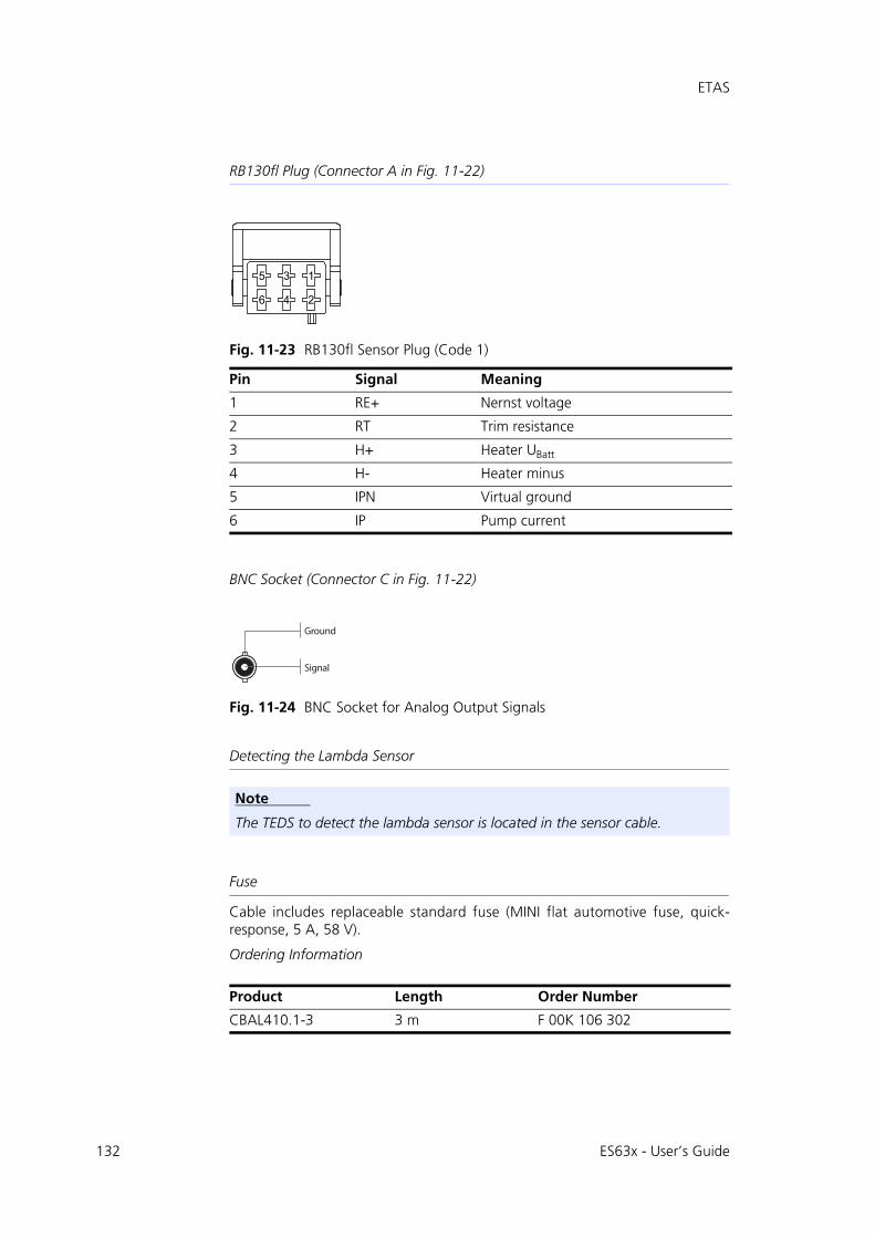
132
ETAS
RB130fl Plug (Connector A in Fig. 11-22)
Fig. 11-23 RB130fl Sensor Plug (Code 1)
BNC Socket (Connector C in Fig. 11-22)
Fig. 11-24 BNC Socket for Analog Output Signals
Detecting the Lambda Sensor
Fuse
Cable includes replaceable standard fuse (MINI flat automotive fuse, quick-response, 5 A, 58 V).
Ordering Information
Pin Signal Meaning
1 RE+ Nernst voltage
2 RT Trim resistance
3 H+ Heater UBatt
4 H- Heater minus
5 IPN Virtual ground
6 IP Pump current
Note
The TEDS to detect the lambda sensor is located in the sensor cable.
Product Length Order Number
CBAL410.1-3 3 m F 00K 106 302
5 3 1
6 4 2
Ground
Signal
ES63x - User’s Guide

ETAS
11.5.3 CBAL4105.1 Cable
Fig. 11-25 CBAL4105.1 Cable
Usage
Cable for Bosch Lambda Sensors LSU4.2 and LSU4.7 (Code 1)
Cable Plugs
PlugFig. 11-22
Comment
A RB130fl plug (Code 1) for the lambda sensor
B MC lamella connector for the external supply of the sensor heating (with inverse-polarity protection, overvoltage protection and cur-rent limitation)
Red connector = plus, black connector = minus
C BNC socket for analog output signals
D Input for powering on the heating for the sensor heating when the module is on “Standby”Sensor heating on: +9 V to +28 V
On delivery, the end of the cable is fixed as a loop in the shrinkage tube of the sensor cable. This must be pulled out to use the cable.
A
B
CD
ES63x - User’s Guide 133

134
ETAS
RB130fl Plug (Connector A in Fig. 11-22)
Fig. 11-26 RB130fl Sensor Plug (Code 1)
BNC Socket (Connector C in Fig. 11-22)
Fig. 11-27 BNC Socket for Analog Output Signals
Detecting the Lambda Sensor
Fuse
Cable includes replaceable standard fuse (MINI flat automotive fuse, quick-response, 5 A, 58 V).
Ordering Information
Pin Signal Meaning
1 RE+ Nernst voltage
2 RT Trim resistance
3 H+ Heater UBatt
4 H- Heater minus
5 IPN Virtual ground
6 IP Pump current
Note
The TEDS to detect the lambda sensor is located in the sensor cable.
Product Length Order Number
CBAL4105.1-3 3 m F 00K 110 033
5 3 1
6 4 2
Ground
Signal
ES63x - User’s Guide
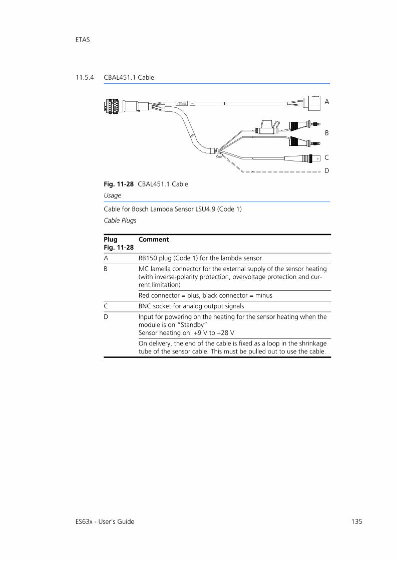
ETAS
11.5.4 CBAL451.1 Cable
Fig. 11-28 CBAL451.1 Cable
Usage
Cable for Bosch Lambda Sensor LSU4.9 (Code 1)
Cable Plugs
PlugFig. 11-28
Comment
A RB150 plug (Code 1) for the lambda sensor
B MC lamella connector for the external supply of the sensor heating (with inverse-polarity protection, overvoltage protection and cur-rent limitation)
Red connector = plus, black connector = minus
C BNC socket for analog output signals
D Input for powering on the heating for the sensor heating when the module is on “Standby”Sensor heating on: +9 V to +28 V
On delivery, the end of the cable is fixed as a loop in the shrinkage tube of the sensor cable. This must be pulled out to use the cable.
A
B
C
D
ES63x - User’s Guide 135

136
ETAS
RB150 Plug (Connector A in Fig. 11-28)
Fig. 11-29 RB150 Sensor Plug (Code 1)
BNC Socket (Connector C in Fig. 11-28
Fig. 11-30 BNC Socket for Analog Output Signals
Detecting the Lambda Sensor
Fuse
Cable includes replaceable standard fuse (MINI flat automotive fuse, quick-response, 5 A, 58 V).
Ordering Information
Pin Signal Meaning
1 IP Pump current
2 IPN Virtual ground
3 H- Heater minus
4 H+ Heater UBatt
5 RT Trim resistance
6 RE+ Nernst voltage
Note
The TEDS to detect the lambda sensor is located in the sensor cable.
Product Length Order Number
CBAL451.1-3 3 m F 00K 105 926
531
642
Ground
Signal
ES63x - User’s Guide
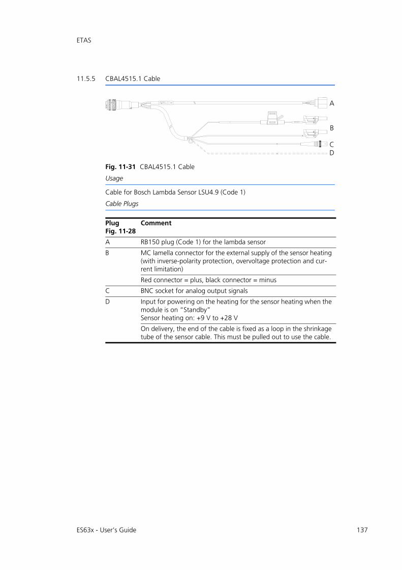
ETAS
11.5.5 CBAL4515.1 Cable
Fig. 11-31 CBAL4515.1 Cable
Usage
Cable for Bosch Lambda Sensor LSU4.9 (Code 1)
Cable Plugs
PlugFig. 11-28
Comment
A RB150 plug (Code 1) for the lambda sensor
B MC lamella connector for the external supply of the sensor heating (with inverse-polarity protection, overvoltage protection and cur-rent limitation)
Red connector = plus, black connector = minus
C BNC socket for analog output signals
D Input for powering on the heating for the sensor heating when the module is on “Standby”Sensor heating on: +9 V to +28 V
On delivery, the end of the cable is fixed as a loop in the shrinkage tube of the sensor cable. This must be pulled out to use the cable.
A
B
CD
ES63x - User’s Guide 137
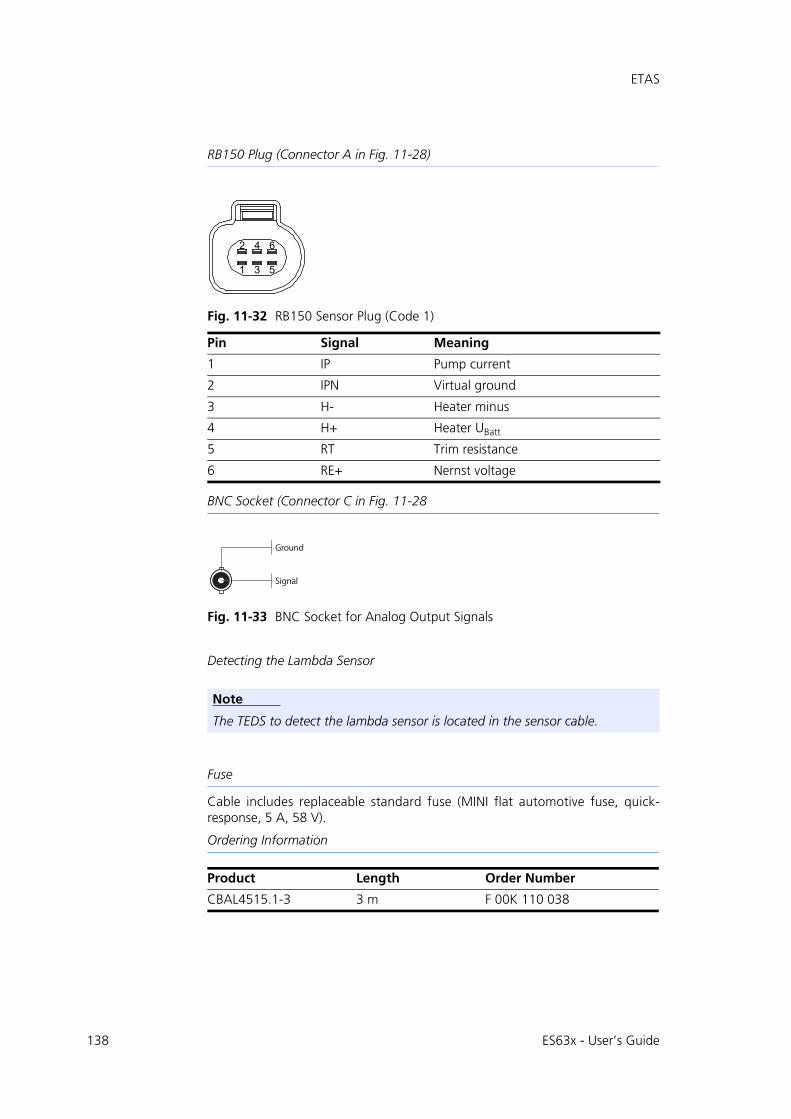
138
ETAS
RB150 Plug (Connector A in Fig. 11-28)
Fig. 11-32 RB150 Sensor Plug (Code 1)
BNC Socket (Connector C in Fig. 11-28
Fig. 11-33 BNC Socket for Analog Output Signals
Detecting the Lambda Sensor
Fuse
Cable includes replaceable standard fuse (MINI flat automotive fuse, quick-response, 5 A, 58 V).
Ordering Information
Pin Signal Meaning
1 IP Pump current
2 IPN Virtual ground
3 H- Heater minus
4 H+ Heater UBatt
5 RT Trim resistance
6 RE+ Nernst voltage
Note
The TEDS to detect the lambda sensor is located in the sensor cable.
Product Length Order Number
CBAL4515.1-3 3 m F 00K 110 038
531
642
Ground
Signal
ES63x - User’s Guide

ETAS
11.5.6 CBAL452.1 Cable
Fig. 11-34 CBAL452.1 Cable
Usage
Cable for Bosch Lambda Sensor LSU4.9 (Code 1)
Cable Plugs
PlugFig. 11-34
Comment
A RB150 plug (Code 1) for the lambda sensor
B MC lamella connector for the external supply of the sensor heating (with inverse-polarity protection, overvoltage protection and cur-rent limitation)
Red connector = plus, black connector = minus
C Input for powering on the heating for the sensor heating when the module is on “Standby”Sensor heating on: +9 V to +28 V
On delivery, the end of the cable is fixed as a loop in the shrinkage tube of the sensor cable. This must be pulled out to use the cable.
A
B
C
ES63x - User’s Guide 139

140
ETAS
RB150 Plug (Connector A in Fig. 11-34)
Fig. 11-35 RB150 Sensor Plug (Code 1)
Detecting the Lambda Sensor
Fuse
Cable includes replaceable standard fuse (MINI flat automotive fuse, quick-response, 5 A, 58 V).
Ordering Information
Pin Signal Meaning
1 IP Pump current
2 IPN Virtual ground
3 H- Heater minus
4 H+ Heater UBatt
5 RT Trim resistance
6 RE+ Nernst voltage
Note
The TEDS to detect the lambda sensor is located in the sensor cable.
Product Length Order Number
CBAL452.1-3 3 m F 00K 106 127
531
642
ES63x - User’s Guide
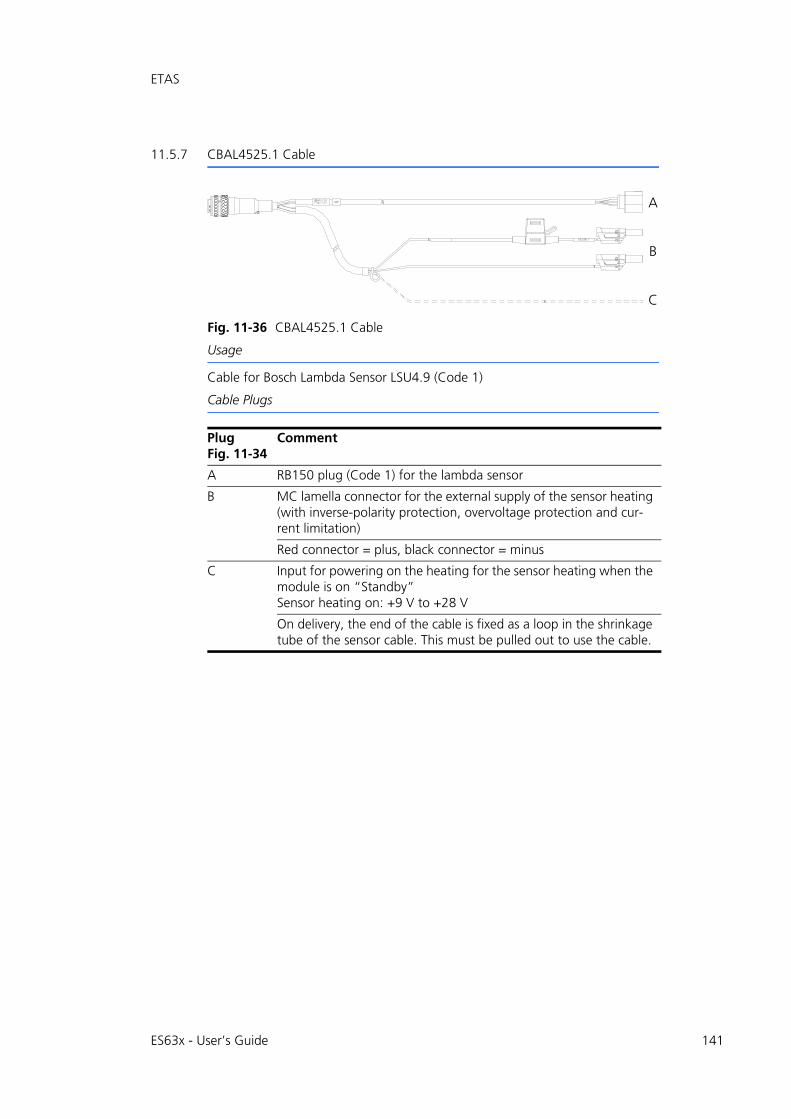
ETAS
11.5.7 CBAL4525.1 Cable
Fig. 11-36 CBAL4525.1 Cable
Usage
Cable for Bosch Lambda Sensor LSU4.9 (Code 1)
Cable Plugs
PlugFig. 11-34
Comment
A RB150 plug (Code 1) for the lambda sensor
B MC lamella connector for the external supply of the sensor heating (with inverse-polarity protection, overvoltage protection and cur-rent limitation)
Red connector = plus, black connector = minus
C Input for powering on the heating for the sensor heating when the module is on “Standby”Sensor heating on: +9 V to +28 V
On delivery, the end of the cable is fixed as a loop in the shrinkage tube of the sensor cable. This must be pulled out to use the cable.
A
B
C
ES63x - User’s Guide 141
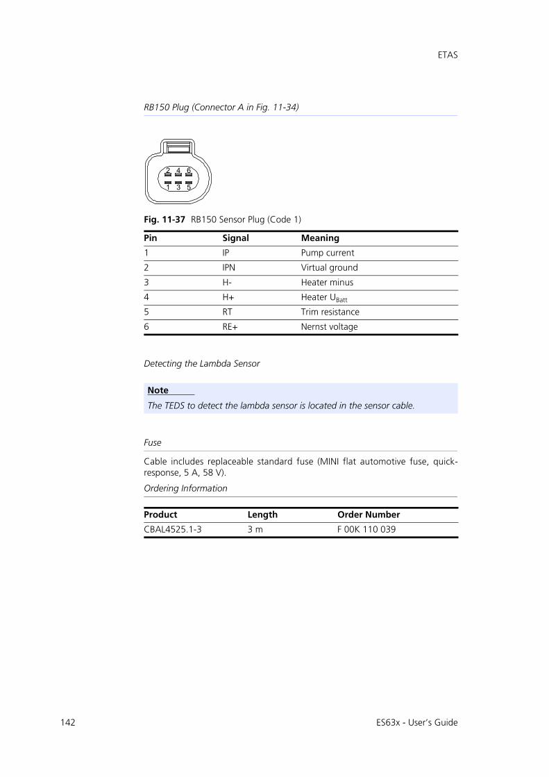
142
ETAS
RB150 Plug (Connector A in Fig. 11-34)
Fig. 11-37 RB150 Sensor Plug (Code 1)
Detecting the Lambda Sensor
Fuse
Cable includes replaceable standard fuse (MINI flat automotive fuse, quick-response, 5 A, 58 V).
Ordering Information
Pin Signal Meaning
1 IP Pump current
2 IPN Virtual ground
3 H- Heater minus
4 H+ Heater UBatt
5 RT Trim resistance
6 RE+ Nernst voltage
Note
The TEDS to detect the lambda sensor is located in the sensor cable.
Product Length Order Number
CBAL4525.1-3 3 m F 00K 110 039
531
642
ES63x - User’s Guide
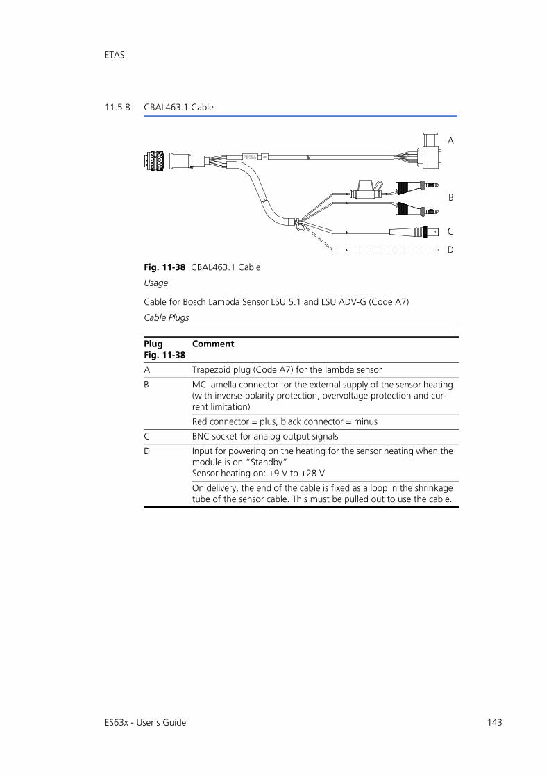
ETAS
11.5.8 CBAL463.1 Cable
Fig. 11-38 CBAL463.1 Cable
Usage
Cable for Bosch Lambda Sensor LSU 5.1 and LSU ADV-G (Code A7)
Cable Plugs
PlugFig. 11-38
Comment
A Trapezoid plug (Code A7) for the lambda sensor
B MC lamella connector for the external supply of the sensor heating (with inverse-polarity protection, overvoltage protection and cur-rent limitation)
Red connector = plus, black connector = minus
C BNC socket for analog output signals
D Input for powering on the heating for the sensor heating when the module is on “Standby”Sensor heating on: +9 V to +28 V
On delivery, the end of the cable is fixed as a loop in the shrinkage tube of the sensor cable. This must be pulled out to use the cable.
A
B
D
C
ES63x - User’s Guide 143

144
ETAS
Trapezoid Plug (Connector A in Fig. 11-38)
Fig. 11-39 Trapezoid Plug (Code A7)
BNC Socket (Connector C in Fig. 11-38)
Fig. 11-40 BNC Socket for Analog Output Signals
Detecting the Lambda Sensor
Fuse
Cable includes replaceable standard fuse (MINI flat automotive fuse, quick-response, 5 A, 58 V).
Ordering Information
Pin Signal Meaning
1 IP Pump current
2 IPN Virtual ground
3 H- Heater minus
4 H+ Heater UBatt
5 TEDS+ TEDS+
6 RE+ Nernst voltage
7 TEDS- TEDS-
Note
The TEDS to detect the lambda sensor is located in the sensor cable.
Product Length Order Number
CBAL463.1-3 3 m F 00K 106 310
321
7654
Ground
Signal
ES63x - User’s Guide
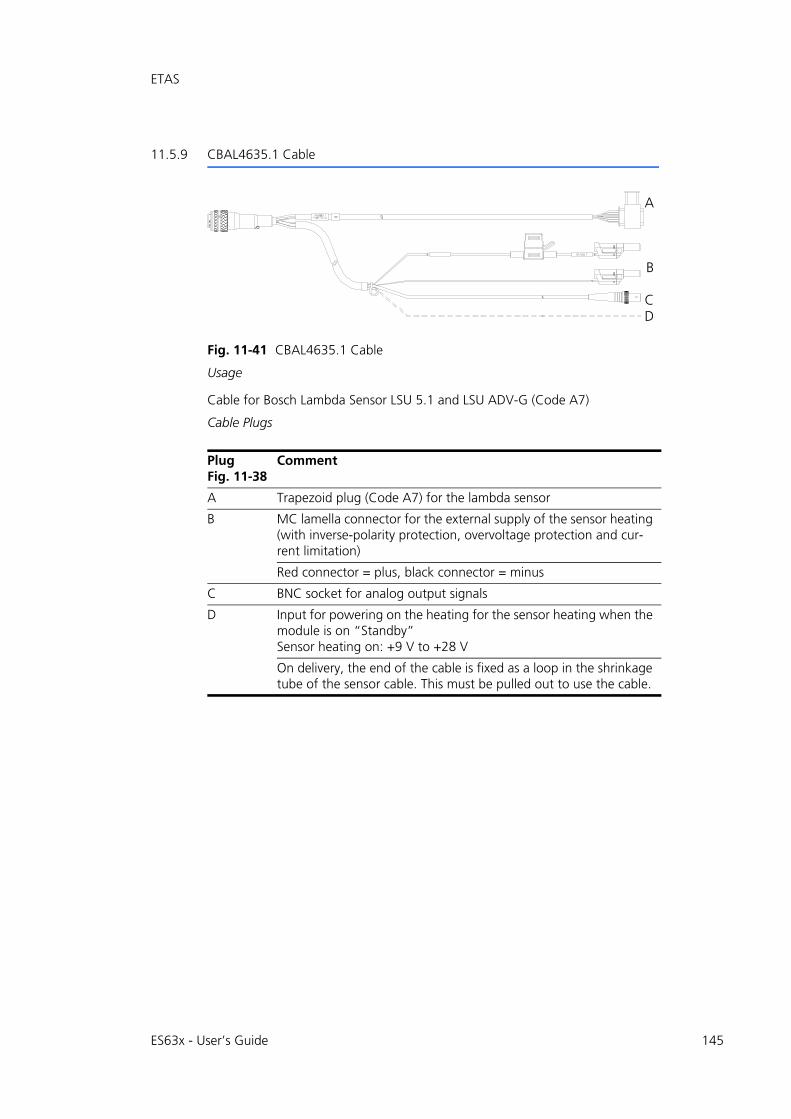
ETAS
11.5.9 CBAL4635.1 Cable
Fig. 11-41 CBAL4635.1 Cable
Usage
Cable for Bosch Lambda Sensor LSU 5.1 and LSU ADV-G (Code A7)
Cable Plugs
PlugFig. 11-38
Comment
A Trapezoid plug (Code A7) for the lambda sensor
B MC lamella connector for the external supply of the sensor heating (with inverse-polarity protection, overvoltage protection and cur-rent limitation)
Red connector = plus, black connector = minus
C BNC socket for analog output signals
D Input for powering on the heating for the sensor heating when the module is on “Standby”Sensor heating on: +9 V to +28 V
On delivery, the end of the cable is fixed as a loop in the shrinkage tube of the sensor cable. This must be pulled out to use the cable.
A
CD
B
ES63x - User’s Guide 145
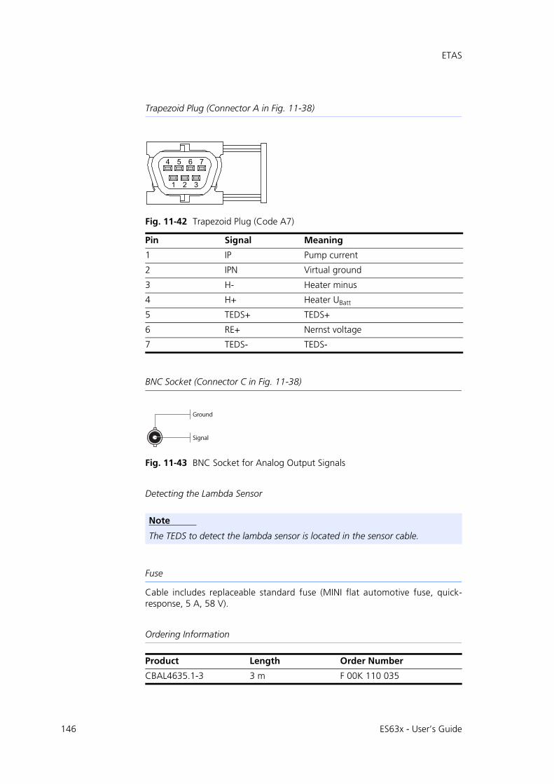
146
ETAS
Trapezoid Plug (Connector A in Fig. 11-38)
Fig. 11-42 Trapezoid Plug (Code A7)
BNC Socket (Connector C in Fig. 11-38)
Fig. 11-43 BNC Socket for Analog Output Signals
Detecting the Lambda Sensor
Fuse
Cable includes replaceable standard fuse (MINI flat automotive fuse, quick-response, 5 A, 58 V).
Ordering Information
Pin Signal Meaning
1 IP Pump current
2 IPN Virtual ground
3 H- Heater minus
4 H+ Heater UBatt
5 TEDS+ TEDS+
6 RE+ Nernst voltage
7 TEDS- TEDS-
Note
The TEDS to detect the lambda sensor is located in the sensor cable.
Product Length Order Number
CBAL4635.1-3 3 m F 00K 110 035
321
7654
Ground
Signal
ES63x - User’s Guide

ETAS
11.5.10 CBAL468.1 Cable
Fig. 11-44 CBAL468.1 Cable
Usage
Cable for Bosch Lamdba Sensor LSU 5.2 (Code 2)
Cable Plugs
RB150 Plug (Connector A in Fig. 11-44)
Fig. 11-45 RB150 Sensor Plug (Code 2)
Plug in Fig. 11-44
Comment
A RB150 plug (Code 1) for the lambda sensor
B Schützinger lamella connector for the external supply of the sen-sor heating (with inverse-polarity protection, overvoltage protec-tion and current limitation)
Red connector = plus, black connector = minus
C BNC socket for analog output signals
Input for powering on the heating for the sensor heating when the module is on “Standby”Sensor heating on: +9 V to +28 V
D On delivery, the end of the cable is fixed as a loop in the shrinkage tube of the sensor cable. This must be pulled out to use the cable.
Red connector = plus, black connector = minus
Pin Signal Meaning
1 IP Pump current
2 IPN Virtual ground
3 H- Heater minus
A
B
CD
ES63x - User’s Guide 147
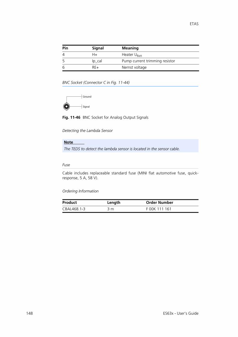
148
ETAS
BNC Socket (Connector C in Fig. 11-44)
Fig. 11-46 BNC Socket for Analog Output Signals
Detecting the Lambda Sensor
Fuse
Cable includes replaceable standard fuse (MINI flat automotive fuse, quick-response, 5 A, 58 V).
Ordering Information
4 H+ Heater UBatt
5 Ip_cal Pump current trimming resistor
6 RE+ Nernst voltage
Note
The TEDS to detect the lambda sensor is located in the sensor cable.
Product Length Order Number
CBAL468.1-3 3 m F 00K 111 161
Pin Signal Meaning
Ground
Signal
ES63x - User’s Guide
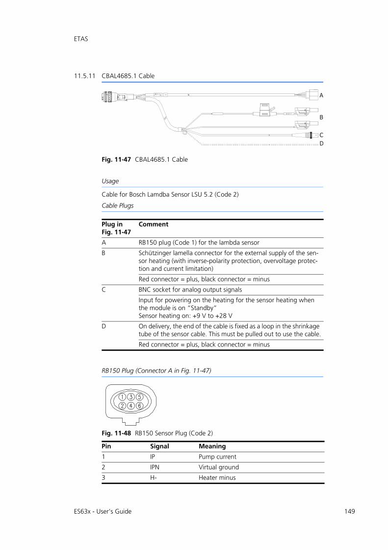
ETAS
11.5.11 CBAL4685.1 Cable
Fig. 11-47 CBAL4685.1 Cable
Usage
Cable for Bosch Lamdba Sensor LSU 5.2 (Code 2)
Cable Plugs
RB150 Plug (Connector A in Fig. 11-47)
Fig. 11-48 RB150 Sensor Plug (Code 2)
Plug in Fig. 11-47
Comment
A RB150 plug (Code 1) for the lambda sensor
B Schützinger lamella connector for the external supply of the sen-sor heating (with inverse-polarity protection, overvoltage protec-tion and current limitation)
Red connector = plus, black connector = minus
C BNC socket for analog output signals
Input for powering on the heating for the sensor heating when the module is on “Standby”Sensor heating on: +9 V to +28 V
D On delivery, the end of the cable is fixed as a loop in the shrinkage tube of the sensor cable. This must be pulled out to use the cable.
Red connector = plus, black connector = minus
Pin Signal Meaning
1 IP Pump current
2 IPN Virtual ground
3 H- Heater minus
A
B
CD
ES63x - User’s Guide 149

150
ETAS
BNC Socket (Connector C in Fig. 11-47)
Fig. 11-49 BNC Socket for Analog Output Signals
Detecting the Lambda Sensor
Fuse
Cable includes replaceable standard fuse (MINI flat automotive fuse, quick-response, 5 A, 58 V).
Ordering Information
4 H+ Heater UBatt
5 Ip_cal Pump current trimming resistor
6 RE+ Nernst voltage
Note
The TEDS to detect the lambda sensor is located in the sensor cable.
Product Length Order Number
CBAL4685.1-3 3 m F 00K 111 162
Pin Signal Meaning
Ground
Signal
ES63x - User’s Guide
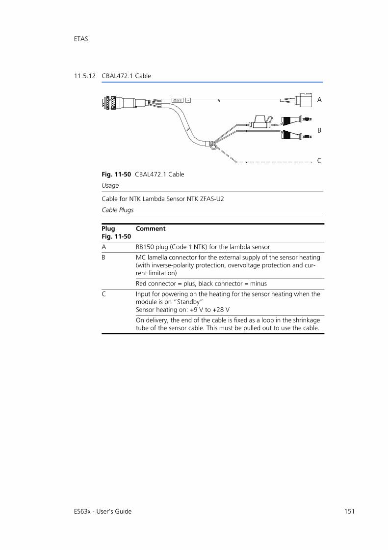
ETAS
11.5.12 CBAL472.1 Cable
Fig. 11-50 CBAL472.1 Cable
Usage
Cable for NTK Lambda Sensor NTK ZFAS-U2
Cable Plugs
PlugFig. 11-50
Comment
A RB150 plug (Code 1 NTK) for the lambda sensor
B MC lamella connector for the external supply of the sensor heating (with inverse-polarity protection, overvoltage protection and cur-rent limitation)
Red connector = plus, black connector = minus
C Input for powering on the heating for the sensor heating when the module is on “Standby”Sensor heating on: +9 V to +28 V
On delivery, the end of the cable is fixed as a loop in the shrinkage tube of the sensor cable. This must be pulled out to use the cable.
A
B
C
ES63x - User’s Guide 151

152
ETAS
RB150 Plug (Connector A in Fig. 11-50)
Fig. 11-51 RB150 Sensor Plug (Code 1 NTK)
Detecting the Lambda Sensor
Fuse
Cable includes replaceable standard fuse (MINI flat automotive fuse, quick-response, 5 A, 58 V).
Ordering Information
Pin Signal Meaning
1 RT Trim resistance
2 IP Pump current
3 H- Heater minus
4 RE+ Nernst voltage
5 H+ Heater UBatt
6 IPN Virtual ground
Note
The TEDS to detect the lambda sensor is located in the sensor cable.
Product Length Order Number
CBAL472.1-3 3 m F 00K 107 313
531
642
ES63x - User’s Guide
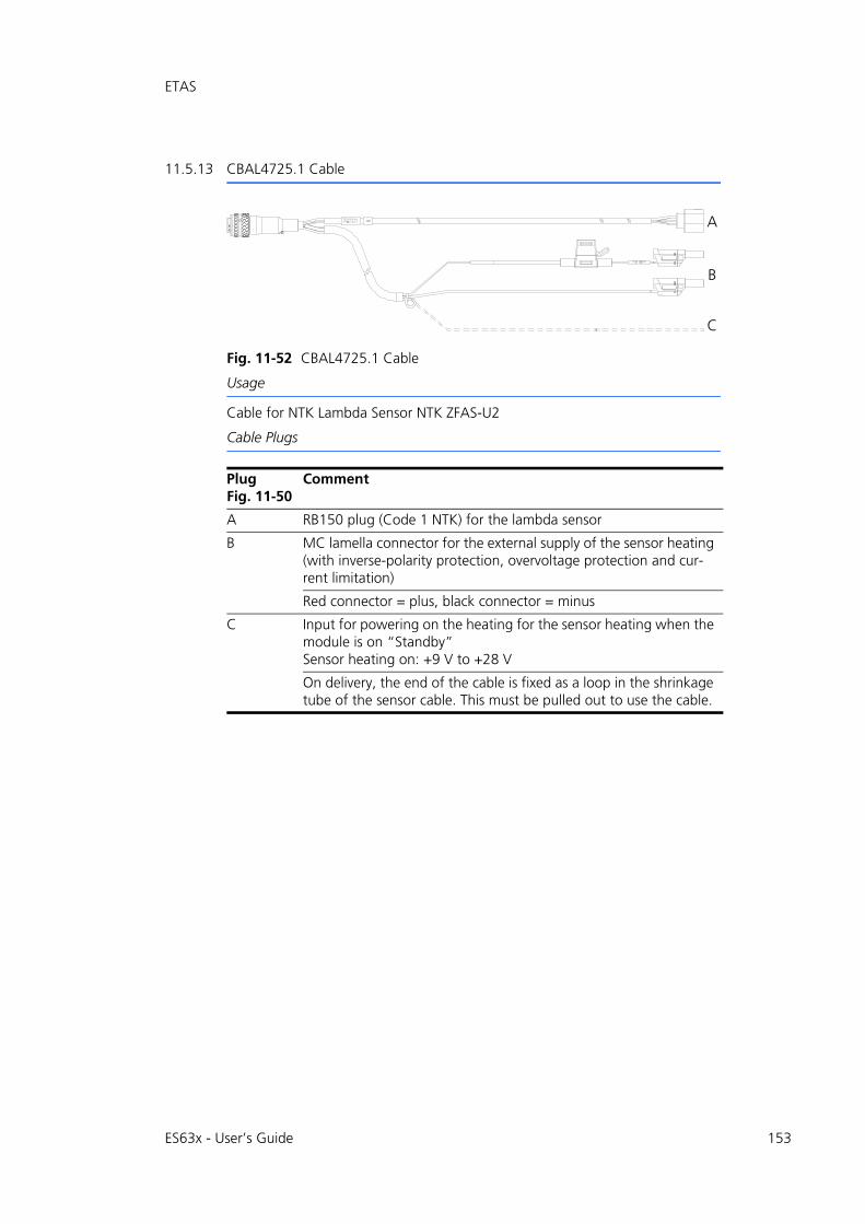
ETAS
11.5.13 CBAL4725.1 Cable
Fig. 11-52 CBAL4725.1 Cable
Usage
Cable for NTK Lambda Sensor NTK ZFAS-U2
Cable Plugs
PlugFig. 11-50
Comment
A RB150 plug (Code 1 NTK) for the lambda sensor
B MC lamella connector for the external supply of the sensor heating (with inverse-polarity protection, overvoltage protection and cur-rent limitation)
Red connector = plus, black connector = minus
C Input for powering on the heating for the sensor heating when the module is on “Standby”Sensor heating on: +9 V to +28 V
On delivery, the end of the cable is fixed as a loop in the shrinkage tube of the sensor cable. This must be pulled out to use the cable.
A
B
C
ES63x - User’s Guide 153

154
ETAS
RB150 Plug (Connector A in Fig. 11-50)
Fig. 11-53 RB150 Sensor Plug (Code 1 NTK)
Detecting the Lambda Sensor
Fuse
Cable includes replaceable standard fuse (MINI flat automotive fuse, quick-response, 5 A, 58 V).
Ordering Information
Pin Signal Meaning
1 RT Trim resistance
2 IP Pump current
3 H- Heater minus
4 RE+ Nernst voltage
5 H+ Heater UBatt
6 IPN Virtual ground
Note
The TEDS to detect the lambda sensor is located in the sensor cable.
Product Length Order Number
CBAL4525.1-3 3 m F 00K 110 040
531
642
ES63x - User’s Guide
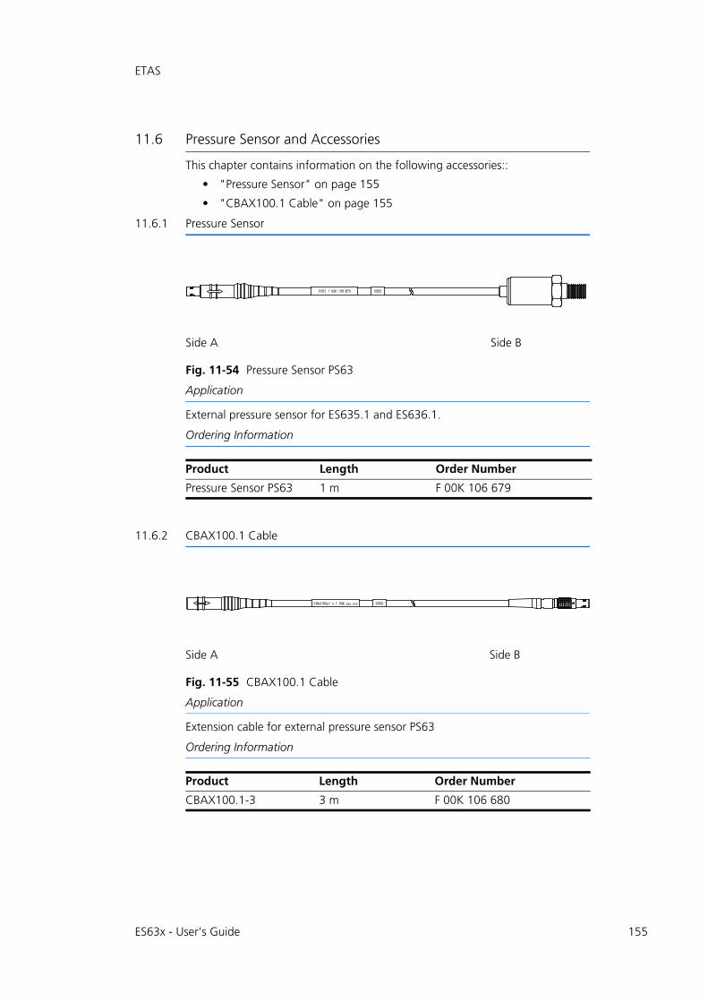
ES63x - User’s Guide 155
ETAS
11.6 Pressure Sensor and Accessories
This chapter contains information on the following accessories::
• "Pressure Sensor" on page 155
• "CBAX100.1 Cable" on page 155
11.6.1 Pressure Sensor
Fig. 11-54 Pressure Sensor PS63
Application
External pressure sensor for ES635.1 and ES636.1.
Ordering Information
11.6.2 CBAX100.1 Cable
Fig. 11-55 CBAX100.1 Cable
Application
Extension cable for external pressure sensor PS63
Ordering Information
Side A Side B
Product Length Order Number
Pressure Sensor PS63 1 m F 00K 106 679
Side A Side B
Product Length Order Number
CBAX100.1-3 3 m F 00K 106 680
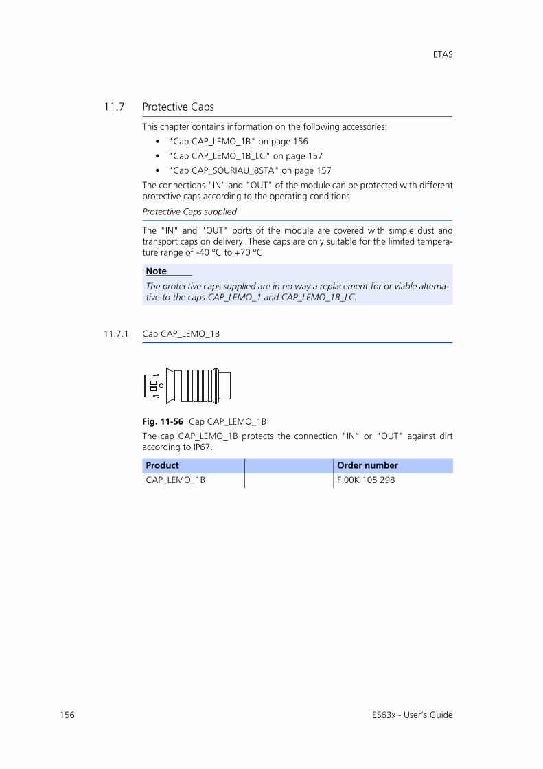
156
ETAS
11.7 Protective Caps
This chapter contains information on the following accessories:
• "Cap CAP_LEMO_1B" on page 156
• "Cap CAP_LEMO_1B_LC" on page 157
• "Cap CAP_SOURIAU_8STA" on page 157
The connections "IN" and "OUT" of the module can be protected with differentprotective caps according to the operating conditions.
Protective Caps supplied
The "IN" and "OUT" ports of the module are covered with simple dust andtransport caps on delivery. These caps are only suitable for the limited tempera-ture range of -40 °C to +70 °C
11.7.1 Cap CAP_LEMO_1B
Fig. 11-56 Cap CAP_LEMO_1B
The cap CAP_LEMO_1B protects the connection "IN" or "OUT" against dirtaccording to IP67.
Note
The protective caps supplied are in no way a replacement for or viable alterna-tive to the caps CAP_LEMO_1 and CAP_LEMO_1B_LC.
Product Order number
CAP_LEMO_1B F 00K 105 298
ES63x - User’s Guide
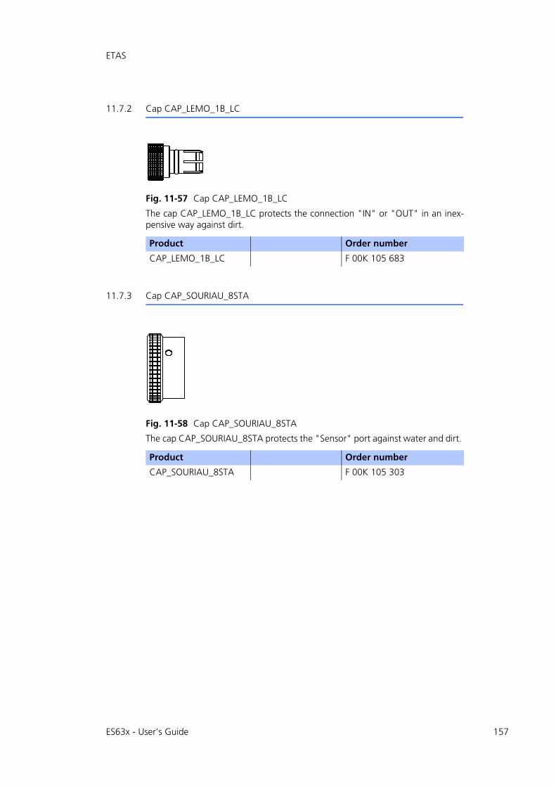
ETAS
11.7.2 Cap CAP_LEMO_1B_LC
Fig. 11-57 Cap CAP_LEMO_1B_LC
The cap CAP_LEMO_1B_LC protects the connection "IN" or "OUT" in an inex-pensive way against dirt.
11.7.3 Cap CAP_SOURIAU_8STA
Fig. 11-58 Cap CAP_SOURIAU_8STA
The cap CAP_SOURIAU_8STA protects the "Sensor" port against water and dirt.
Product Order number
CAP_LEMO_1B_LC F 00K 105 683
Product Order number
CAP_SOURIAU_8STA F 00K 105 303
ES63x - User’s Guide 157

158
Ordering Information ETAS
12 Ordering Information
This chapter contains information on the following topics:
• "Lambda Module" on page 158
• "Lambda Module Sets" on page 159
• "Accessories" on page 163
12.1 Lambda Module
Note
Cables are not part of the scope of supplies of the module and must be ordered separately (see chapter 12.3 on page 163).
Note
If you require customized cables, please contact your ETAS contact partner or [email protected].
Order Name Short Name Order Number
ES630.1 Lambda Module (1-CH) ES630.1 F 00K 106 296
Package Contents
ES630.1 Lambda Module (1-CH),CDROM ES6xx_DRV_SW_CD (driver and tools for ES6xx Daisy Chain Modules Family)
ES631.1 Lambda Module (2-CH) ES631.1 F 00K 106 297
Package Contents
ES631.1 Lambda Module (2-CH),CDROM ES6xx_DRV_SW_CD (driver and tools for ES6xx Daisy Chain Modules Family)
ES635.1 Lambda Module (1-CH) ES635.1 F 00K 106 675
Package Contents
ES635.1 Lambda Module (1-CH),CDROM ES6xx_DRV_SW_CD (driver and tools for ES6xx Daisy Chain Modules Family)
ES636.1 Lambda Module (2-CH) ES636.1 F 00K 106 676
Package Contents
ES636.1 Lambda Module (2-CH),CDROM ES6xx_DRV_SW_CD (driver and tools for ES6xx Daisy Chain Modules Family)
ES63x - User’s Guide
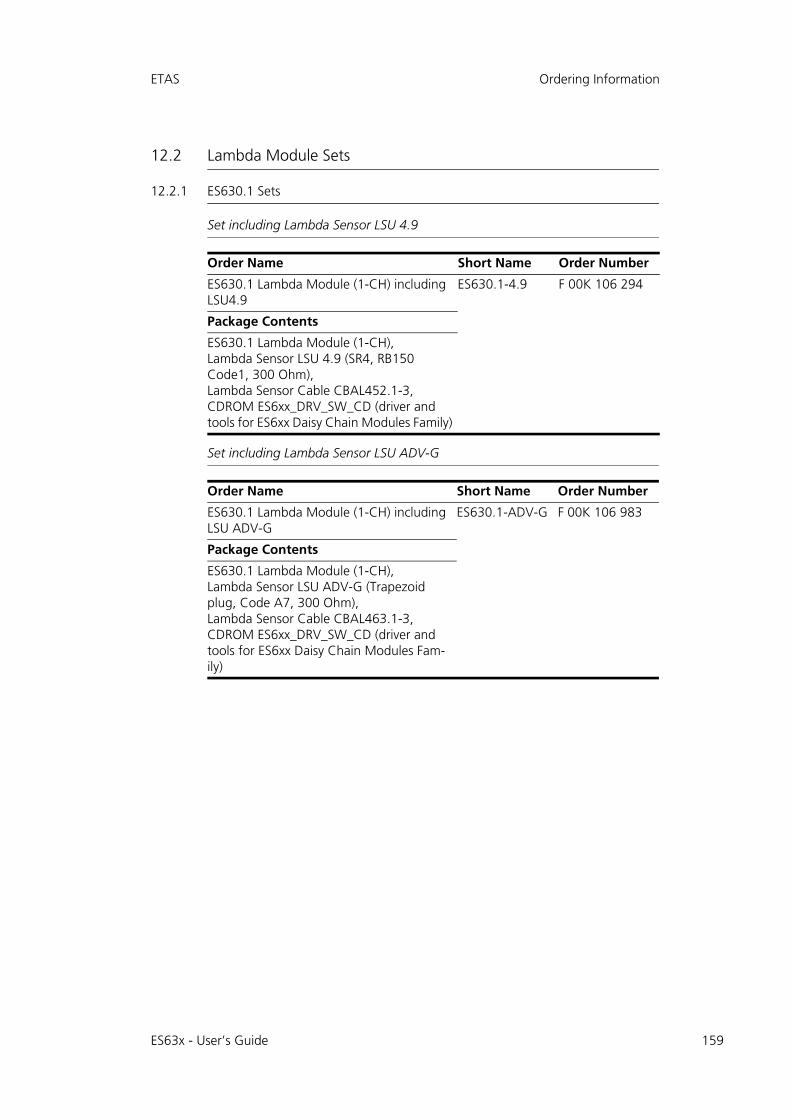
ETAS Ordering Information
12.2 Lambda Module Sets
12.2.1 ES630.1 Sets
Set including Lambda Sensor LSU 4.9
Set including Lambda Sensor LSU ADV-G
Order Name Short Name Order Number
ES630.1 Lambda Module (1-CH) including LSU4.9
ES630.1-4.9 F 00K 106 294
Package Contents
ES630.1 Lambda Module (1-CH),Lambda Sensor LSU 4.9 (SR4, RB150 Code1, 300 Ohm),Lambda Sensor Cable CBAL452.1-3,CDROM ES6xx_DRV_SW_CD (driver and tools for ES6xx Daisy Chain Modules Family)
Order Name Short Name Order Number
ES630.1 Lambda Module (1-CH) including LSU ADV-G
ES630.1-ADV-G F 00K 106 983
Package Contents
ES630.1 Lambda Module (1-CH),Lambda Sensor LSU ADV-G (Trapezoid plug, Code A7, 300 Ohm),Lambda Sensor Cable CBAL463.1-3,CDROM ES6xx_DRV_SW_CD (driver and tools for ES6xx Daisy Chain Modules Fam-ily)
ES63x - User’s Guide 159

160
Ordering Information ETAS
12.2.2 ES631.1 Sets
Set including Lambda Sensor LSU 4.9
Set including Lambda Sensor LSU ADV-G
Order Name Short Name Order Number
ES631.1 Lambda Module (2-CH) including LSU4.9
ES631.1-4.9 F 00K 106 295
Package Contents
ES631.1 Lambda Module (2-CH),2 x Lambda Sensor LSU 4.9 (SR4, RB150 Code1, 300 Ohm),2 x Lambda Sensor Cable CBAL452.1-3,CDROM ES6xx_DRV_SW_CD (driver and tools for ES6xx Daisy Chain Modules Fam-ily)
Order Name Short Name Order Number
ES631.1 Lambda Module (2-CH) including LSU ADV-G
ES631.1-ADV-G F 00K 106 984
Package Contents
ES631.1 Lambda Module (2-CH),2 x Lambda Sensor LSU ADV-G (Trapezoid plug, Code A7, 300 Ohm),2 x Lambda Sensor Cable CBAL463.1-3,CDROM ES6xx_DRV_SW_CD (driver and tools for ES6xx Daisy Chain Modules Fam-ily)
ES63x - User’s Guide
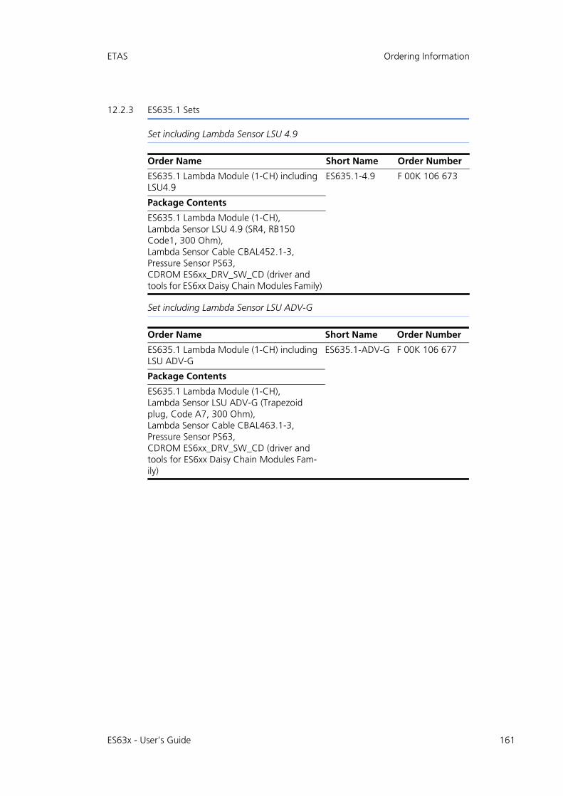
ETAS Ordering Information
12.2.3 ES635.1 Sets
Set including Lambda Sensor LSU 4.9
Set including Lambda Sensor LSU ADV-G
Order Name Short Name Order Number
ES635.1 Lambda Module (1-CH) including LSU4.9
ES635.1-4.9 F 00K 106 673
Package Contents
ES635.1 Lambda Module (1-CH),Lambda Sensor LSU 4.9 (SR4, RB150 Code1, 300 Ohm),Lambda Sensor Cable CBAL452.1-3,Pressure Sensor PS63,CDROM ES6xx_DRV_SW_CD (driver and tools for ES6xx Daisy Chain Modules Family)
Order Name Short Name Order Number
ES635.1 Lambda Module (1-CH) including LSU ADV-G
ES635.1-ADV-G F 00K 106 677
Package Contents
ES635.1 Lambda Module (1-CH),Lambda Sensor LSU ADV-G (Trapezoid plug, Code A7, 300 Ohm),Lambda Sensor Cable CBAL463.1-3,Pressure Sensor PS63,CDROM ES6xx_DRV_SW_CD (driver and tools for ES6xx Daisy Chain Modules Fam-ily)
ES63x - User’s Guide 161
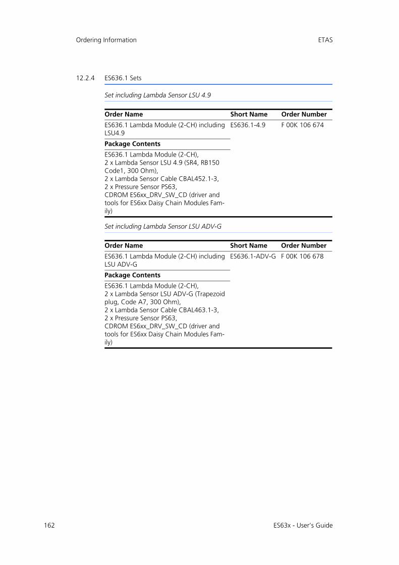
162
Ordering Information ETAS
12.2.4 ES636.1 Sets
Set including Lambda Sensor LSU 4.9
Set including Lambda Sensor LSU ADV-G
Order Name Short Name Order Number
ES636.1 Lambda Module (2-CH) including LSU4.9
ES636.1-4.9 F 00K 106 674
Package Contents
ES636.1 Lambda Module (2-CH),2 x Lambda Sensor LSU 4.9 (SR4, RB150 Code1, 300 Ohm),2 x Lambda Sensor Cable CBAL452.1-3,2 x Pressure Sensor PS63,CDROM ES6xx_DRV_SW_CD (driver and tools for ES6xx Daisy Chain Modules Fam-ily)
Order Name Short Name Order Number
ES636.1 Lambda Module (2-CH) including LSU ADV-G
ES636.1-ADV-G F 00K 106 678
Package Contents
ES636.1 Lambda Module (2-CH),2 x Lambda Sensor LSU ADV-G (Trapezoid plug, Code A7, 300 Ohm),2 x Lambda Sensor Cable CBAL463.1-3,2 x Pressure Sensor PS63,CDROM ES6xx_DRV_SW_CD (driver and tools for ES6xx Daisy Chain Modules Fam-ily)
ES63x - User’s Guide
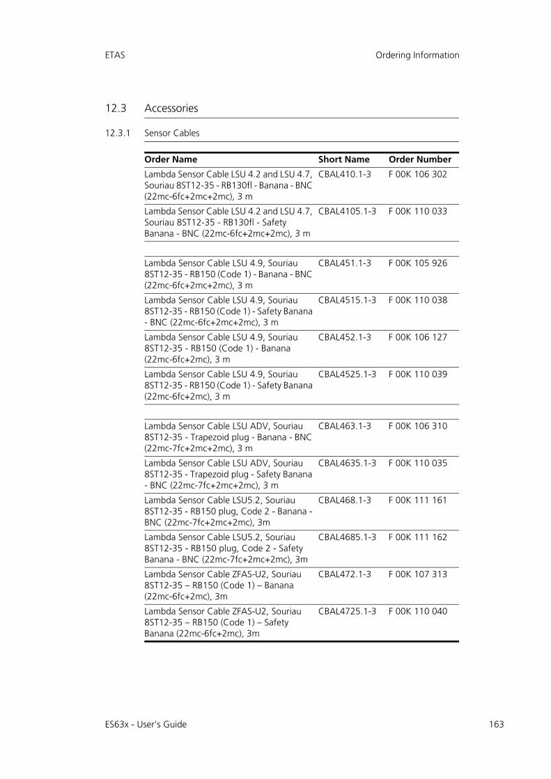
ETAS Ordering Information
12.3 Accessories
12.3.1 Sensor Cables
Order Name Short Name Order Number
Lambda Sensor Cable LSU 4.2 and LSU 4.7, Souriau 8ST12-35 - RB130fl - Banana - BNC (22mc-6fc+2mc+2mc), 3 m
CBAL410.1-3 F 00K 106 302
Lambda Sensor Cable LSU 4.2 and LSU 4.7, Souriau 8ST12-35 - RB130fl - Safety Banana - BNC (22mc-6fc+2mc+2mc), 3 m
CBAL4105.1-3 F 00K 110 033
Lambda Sensor Cable LSU 4.9, Souriau 8ST12-35 - RB150 (Code 1) - Banana - BNC (22mc-6fc+2mc+2mc), 3 m
CBAL451.1-3 F 00K 105 926
Lambda Sensor Cable LSU 4.9, Souriau 8ST12-35 - RB150 (Code 1) - Safety Banana - BNC (22mc-6fc+2mc+2mc), 3 m
CBAL4515.1-3 F 00K 110 038
Lambda Sensor Cable LSU 4.9, Souriau 8ST12-35 - RB150 (Code 1) - Banana (22mc-6fc+2mc), 3 m
CBAL452.1-3 F 00K 106 127
Lambda Sensor Cable LSU 4.9, Souriau 8ST12-35 - RB150 (Code 1) - Safety Banana (22mc-6fc+2mc), 3 m
CBAL4525.1-3 F 00K 110 039
Lambda Sensor Cable LSU ADV, Souriau 8ST12-35 - Trapezoid plug - Banana - BNC (22mc-7fc+2mc+2mc), 3 m
CBAL463.1-3 F 00K 106 310
Lambda Sensor Cable LSU ADV, Souriau 8ST12-35 - Trapezoid plug - Safety Banana - BNC (22mc-7fc+2mc+2mc), 3 m
CBAL4635.1-3 F 00K 110 035
Lambda Sensor Cable LSU5.2, Souriau 8ST12-35 - RB150 plug, Code 2 - Banana - BNC (22mc-7fc+2mc+2mc), 3m
CBAL468.1-3 F 00K 111 161
Lambda Sensor Cable LSU5.2, Souriau 8ST12-35 - RB150 plug, Code 2 - Safety Banana - BNC (22mc-7fc+2mc+2mc), 3m
CBAL4685.1-3 F 00K 111 162
Lambda Sensor Cable ZFAS-U2, Souriau 8ST12-35 – RB150 (Code 1) – Banana (22mc-6fc+2mc), 3m
CBAL472.1-3 F 00K 107 313
Lambda Sensor Cable ZFAS-U2, Souriau 8ST12-35 – RB150 (Code 1) – Safety Banana (22mc-6fc+2mc), 3m
CBAL4725.1-3 F 00K 110 040
ES63x - User’s Guide 163
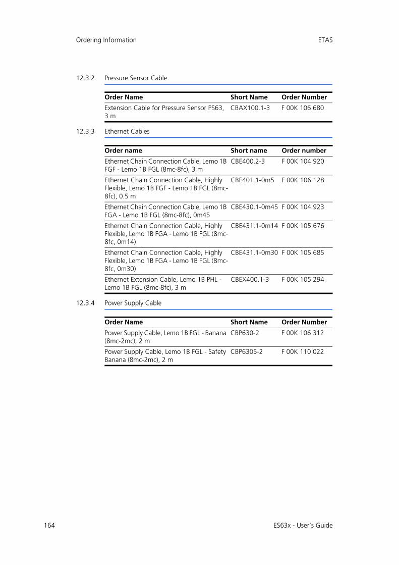
164
Ordering Information ETAS
12.3.2 Pressure Sensor Cable
12.3.3 Ethernet Cables
12.3.4 Power Supply Cable
Order Name Short Name Order Number
Extension Cable for Pressure Sensor PS63, 3 m
CBAX100.1-3 F 00K 106 680
Order name Short name Order number
Ethernet Chain Connection Cable, Lemo 1B FGF - Lemo 1B FGL (8mc-8fc), 3 m
CBE400.2-3 F 00K 104 920
Ethernet Chain Connection Cable, Highly Flexible, Lemo 1B FGF - Lemo 1B FGL (8mc-8fc), 0.5 m
CBE401.1-0m5 F 00K 106 128
Ethernet Chain Connection Cable, Lemo 1B FGA - Lemo 1B FGL (8mc-8fc), 0m45
CBE430.1-0m45 F 00K 104 923
Ethernet Chain Connection Cable, Highly Flexible, Lemo 1B FGA - Lemo 1B FGL (8mc-8fc, 0m14)
CBE431.1-0m14 F 00K 105 676
Ethernet Chain Connection Cable, Highly Flexible, Lemo 1B FGA - Lemo 1B FGL (8mc-8fc, 0m30)
CBE431.1-0m30 F 00K 105 685
Ethernet Extension Cable, Lemo 1B PHL - Lemo 1B FGL (8mc-8fc), 3 m
CBEX400.1-3 F 00K 105 294
Order Name Short Name Order Number
Power Supply Cable, Lemo 1B FGL - Banana (8mc-2mc), 2 m
CBP630-2 F 00K 106 312
Power Supply Cable, Lemo 1B FGL - Safety Banana (8mc-2mc), 2 m
CBP6305-2 F 00K 110 022
ES63x - User’s Guide
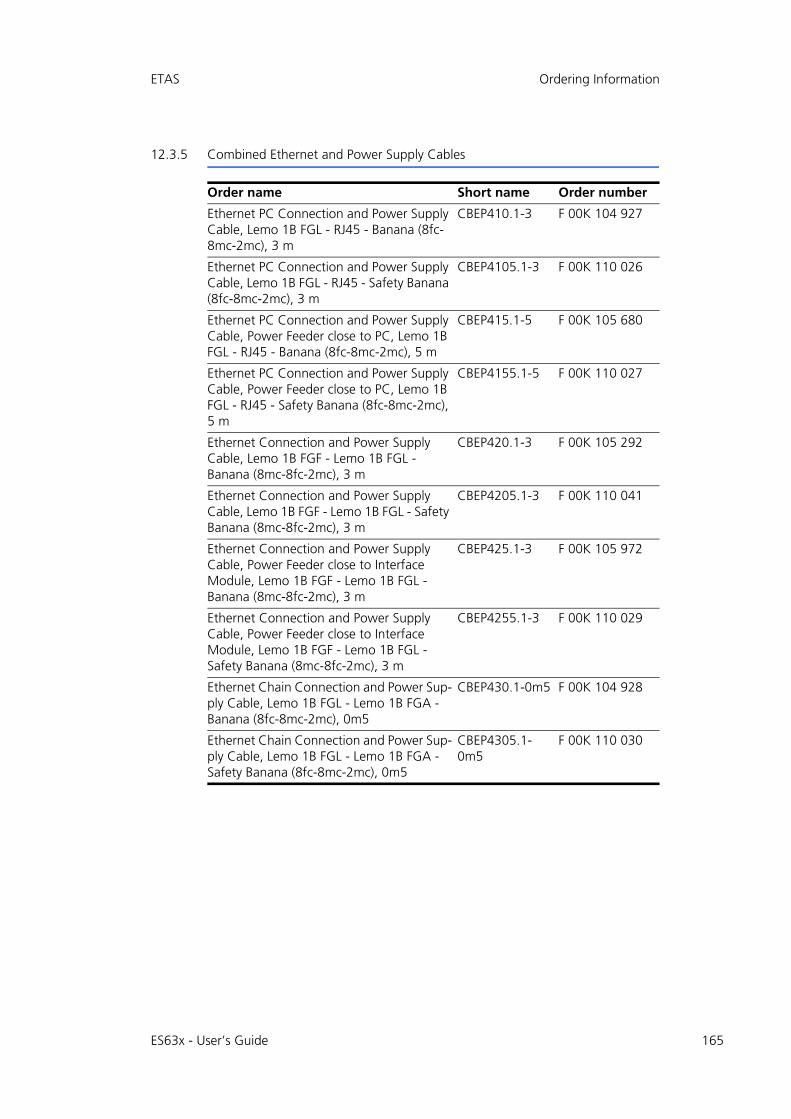
ETAS Ordering Information
12.3.5 Combined Ethernet and Power Supply Cables
Order name Short name Order number
Ethernet PC Connection and Power Supply Cable, Lemo 1B FGL - RJ45 - Banana (8fc-8mc-2mc), 3 m
CBEP410.1-3 F 00K 104 927
Ethernet PC Connection and Power Supply Cable, Lemo 1B FGL - RJ45 - Safety Banana (8fc-8mc-2mc), 3 m
CBEP4105.1-3 F 00K 110 026
Ethernet PC Connection and Power Supply Cable, Power Feeder close to PC, Lemo 1B FGL - RJ45 - Banana (8fc-8mc-2mc), 5 m
CBEP415.1-5 F 00K 105 680
Ethernet PC Connection and Power Supply Cable, Power Feeder close to PC, Lemo 1B FGL - RJ45 - Safety Banana (8fc-8mc-2mc), 5 m
CBEP4155.1-5 F 00K 110 027
Ethernet Connection and Power Supply Cable, Lemo 1B FGF - Lemo 1B FGL - Banana (8mc-8fc-2mc), 3 m
CBEP420.1-3 F 00K 105 292
Ethernet Connection and Power Supply Cable, Lemo 1B FGF - Lemo 1B FGL - Safety Banana (8mc-8fc-2mc), 3 m
CBEP4205.1-3 F 00K 110 041
Ethernet Connection and Power Supply Cable, Power Feeder close to Interface Module, Lemo 1B FGF - Lemo 1B FGL - Banana (8mc-8fc-2mc), 3 m
CBEP425.1-3 F 00K 105 972
Ethernet Connection and Power Supply Cable, Power Feeder close to Interface Module, Lemo 1B FGF - Lemo 1B FGL - Safety Banana (8mc-8fc-2mc), 3 m
CBEP4255.1-3 F 00K 110 029
Ethernet Chain Connection and Power Sup-ply Cable, Lemo 1B FGL - Lemo 1B FGA - Banana (8fc-8mc-2mc), 0m5
CBEP430.1-0m5 F 00K 104 928
Ethernet Chain Connection and Power Sup-ply Cable, Lemo 1B FGL - Lemo 1B FGA - Safety Banana (8fc-8mc-2mc), 0m5
CBEP4305.1-0m5
F 00K 110 030
ES63x - User’s Guide 165
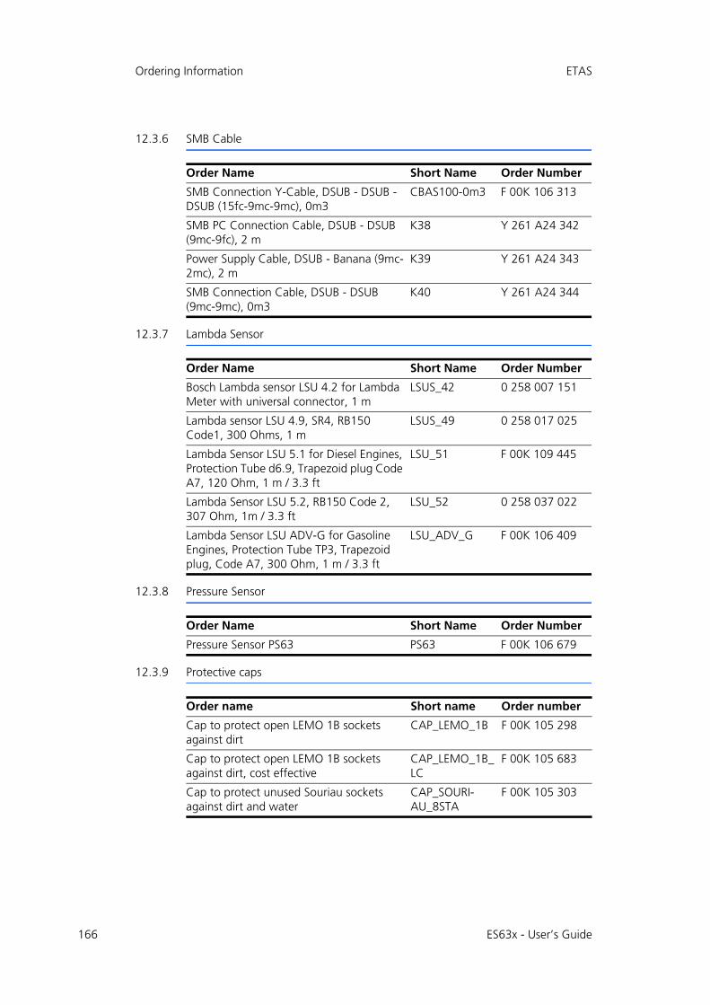
166
Ordering Information ETAS
12.3.6 SMB Cable
12.3.7 Lambda Sensor
12.3.8 Pressure Sensor
12.3.9 Protective caps
Order Name Short Name Order Number
SMB Connection Y-Cable, DSUB - DSUB - DSUB (15fc-9mc-9mc), 0m3
CBAS100-0m3 F 00K 106 313
SMB PC Connection Cable, DSUB - DSUB (9mc-9fc), 2 m
K38 Y 261 A24 342
Power Supply Cable, DSUB - Banana (9mc-2mc), 2 m
K39 Y 261 A24 343
SMB Connection Cable, DSUB - DSUB (9mc-9mc), 0m3
K40 Y 261 A24 344
Order Name Short Name Order Number
Bosch Lambda sensor LSU 4.2 for Lambda Meter with universal connector, 1 m
LSUS_42 0 258 007 151
Lambda sensor LSU 4.9, SR4, RB150 Code1, 300 Ohms, 1 m
LSUS_49 0 258 017 025
Lambda Sensor LSU 5.1 for Diesel Engines, Protection Tube d6.9, Trapezoid plug Code A7, 120 Ohm, 1 m / 3.3 ft
LSU_51 F 00K 109 445
Lambda Sensor LSU 5.2, RB150 Code 2, 307 Ohm, 1m / 3.3 ft
LSU_52 0 258 037 022
Lambda Sensor LSU ADV-G for Gasoline Engines, Protection Tube TP3, Trapezoid plug, Code A7, 300 Ohm, 1 m / 3.3 ft
LSU_ADV_G F 00K 106 409
Order Name Short Name Order Number
Pressure Sensor PS63 PS63 F 00K 106 679
Order name Short name Order number
Cap to protect open LEMO 1B sockets against dirt
CAP_LEMO_1B F 00K 105 298
Cap to protect open LEMO 1B sockets against dirt, cost effective
CAP_LEMO_1B_LC
F 00K 105 683
Cap to protect unused Souriau sockets against dirt and water
CAP_SOURI-AU_8STA
F 00K 105 303
ES63x - User’s Guide
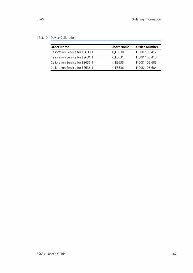
ETAS Ordering Information
12.3.10 Device Calibration
Order Name Short Name Order Number
Calibration Service for ES630.1 K_ES630 F 00K 106 412
Calibration Service for ES631.1 K_ES631 F 00K 106 413
Calibration Service for ES635.1 K_ES635 F 00K 106 683
Calibration Service for ES636.1 K_ES636 F 00K 106 684
ES63x - User’s Guide 167
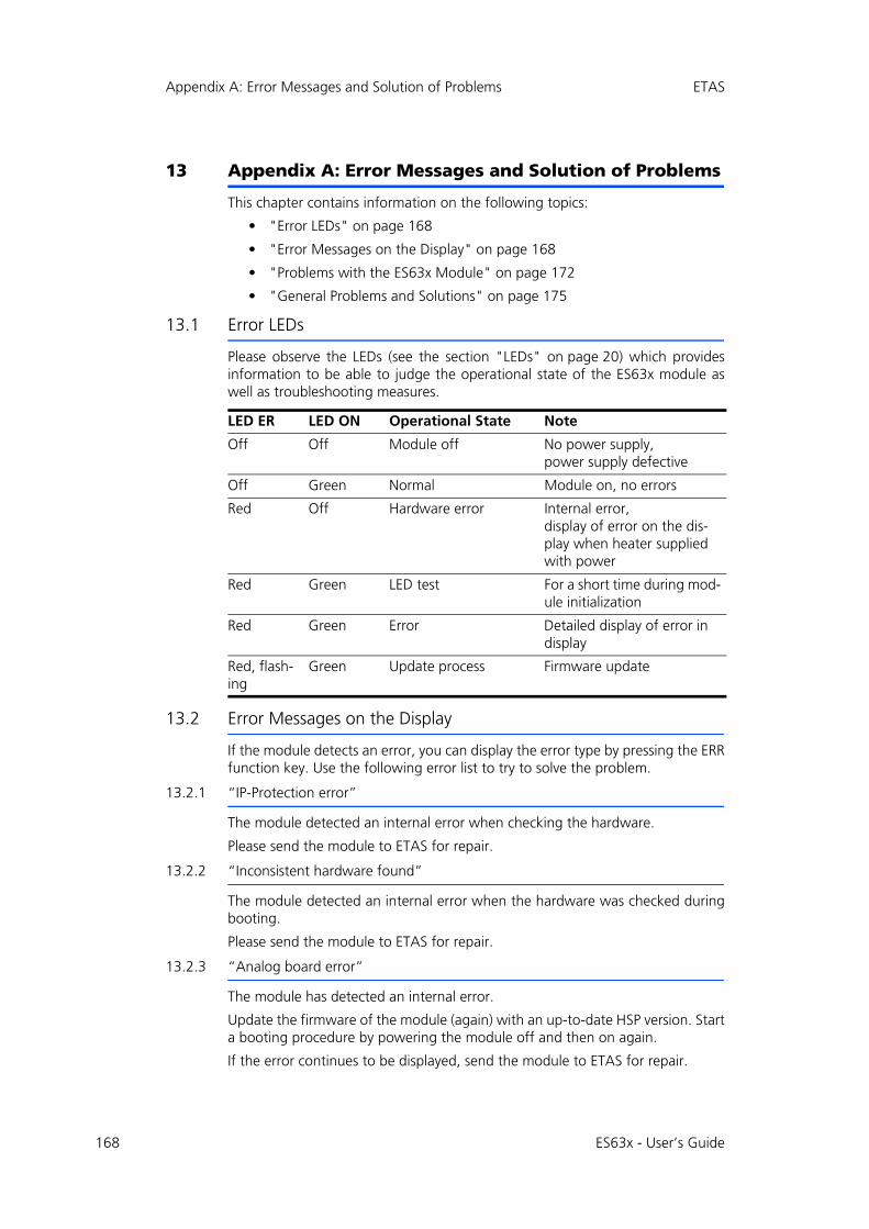
168
Appendix A: Error Messages and Solution of Problems ETAS
13 Appendix A: Error Messages and Solution of Problems
This chapter contains information on the following topics:
• "Error LEDs" on page 168
• "Error Messages on the Display" on page 168
• "Problems with the ES63x Module" on page 172
• "General Problems and Solutions" on page 175
13.1 Error LEDs
Please observe the LEDs (see the section "LEDs" on page 20) which providesinformation to be able to judge the operational state of the ES63x module aswell as troubleshooting measures.
13.2 Error Messages on the Display
If the module detects an error, you can display the error type by pressing the ERRfunction key. Use the following error list to try to solve the problem.
13.2.1 “IP-Protection error”
The module detected an internal error when checking the hardware.
Please send the module to ETAS for repair.
13.2.2 “Inconsistent hardware found”
The module detected an internal error when the hardware was checked duringbooting.
Please send the module to ETAS for repair.
13.2.3 “Analog board error”
The module has detected an internal error.
Update the firmware of the module (again) with an up-to-date HSP version. Starta booting procedure by powering the module off and then on again.
If the error continues to be displayed, send the module to ETAS for repair.
LED ER LED ON Operational State Note
Off Off Module off No power supply,power supply defective
Off Green Normal Module on, no errors
Red Off Hardware error Internal error,display of error on the dis-play when heater supplied with power
Red Green LED test For a short time during mod-ule initialization
Red Green Error Detailed display of error in display
Red, flash-ing
Green Update process Firmware update
ES63x - User’s Guide
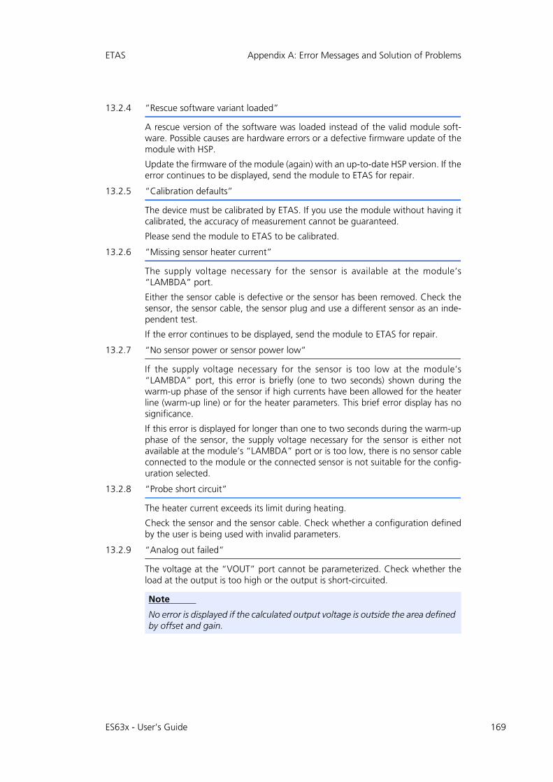
ETAS Appendix A: Error Messages and Solution of Problems
13.2.4 “Rescue software variant loaded”
A rescue version of the software was loaded instead of the valid module soft-ware. Possible causes are hardware errors or a defective firmware update of themodule with HSP.
Update the firmware of the module (again) with an up-to-date HSP version. If theerror continues to be displayed, send the module to ETAS for repair.
13.2.5 “Calibration defaults”
The device must be calibrated by ETAS. If you use the module without having itcalibrated, the accuracy of measurement cannot be guaranteed.
Please send the module to ETAS to be calibrated.
13.2.6 “Missing sensor heater current”
The supply voltage necessary for the sensor is available at the module’s“LAMBDA” port.
Either the sensor cable is defective or the sensor has been removed. Check thesensor, the sensor cable, the sensor plug and use a different sensor as an inde-pendent test.
If the error continues to be displayed, send the module to ETAS for repair.
13.2.7 “No sensor power or sensor power low”
If the supply voltage necessary for the sensor is too low at the module’s“LAMBDA” port, this error is briefly (one to two seconds) shown during thewarm-up phase of the sensor if high currents have been allowed for the heaterline (warm-up line) or for the heater parameters. This brief error display has nosignificance.
If this error is displayed for longer than one to two seconds during the warm-upphase of the sensor, the supply voltage necessary for the sensor is either notavailable at the module’s “LAMBDA” port or is too low, there is no sensor cableconnected to the module or the connected sensor is not suitable for the config-uration selected.
13.2.8 “Probe short circuit”
The heater current exceeds its limit during heating.
Check the sensor and the sensor cable. Check whether a configuration definedby the user is being used with invalid parameters.
13.2.9 “Analog out failed”
The voltage at the “VOUT” port cannot be parameterized. Check whether theload at the output is too high or the output is short-circuited.
Note
No error is displayed if the calculated output voltage is outside the area defined by offset and gain.
ES63x - User’s Guide 169
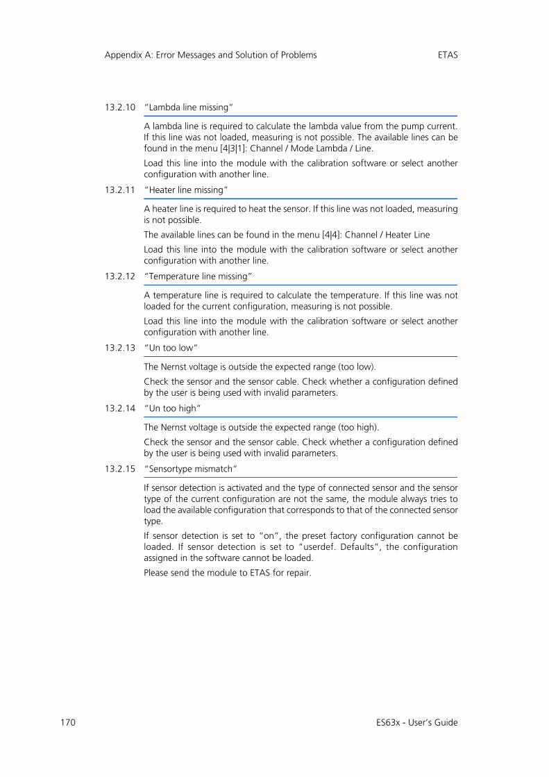
170
Appendix A: Error Messages and Solution of Problems ETAS
13.2.10 “Lambda line missing”
A lambda line is required to calculate the lambda value from the pump current.If this line was not loaded, measuring is not possible. The available lines can befound in the menu [4|3|1]: Channel / Mode Lambda / Line.
Load this line into the module with the calibration software or select anotherconfiguration with another line.
13.2.11 “Heater line missing”
A heater line is required to heat the sensor. If this line was not loaded, measuringis not possible.
The available lines can be found in the menu [4|4]: Channel / Heater Line
Load this line into the module with the calibration software or select anotherconfiguration with another line.
13.2.12 “Temperature line missing”
A temperature line is required to calculate the temperature. If this line was notloaded for the current configuration, measuring is not possible.
Load this line into the module with the calibration software or select anotherconfiguration with another line.
13.2.13 “Un too low”
The Nernst voltage is outside the expected range (too low).
Check the sensor and the sensor cable. Check whether a configuration definedby the user is being used with invalid parameters.
13.2.14 “Un too high”
The Nernst voltage is outside the expected range (too high).
Check the sensor and the sensor cable. Check whether a configuration definedby the user is being used with invalid parameters.
13.2.15 “Sensortype mismatch”
If sensor detection is activated and the type of connected sensor and the sensortype of the current configuration are not the same, the module always tries toload the available configuration that corresponds to that of the connected sensortype.
If sensor detection is set to “on”, the preset factory configuration cannot beloaded. If sensor detection is set to “userdef. Defaults”, the configurationassigned in the software cannot be loaded.
Please send the module to ETAS for repair.
ES63x - User’s Guide

ETAS Appendix A: Error Messages and Solution of Problems
13.2.16 "Excessive heatup time"
The operating temperature of the sensor was not reached within the time dura-tion defined by the heatup line.
Check the sensor, the sensor cable, the sensor plug and use a different sensor asan independent test.
This error requires the sensor to be powered off then on (or unplugged thenreconnected) before operation will restart.
If the error continues to be displayed, send the module to ETAS for repair.
13.2.17 "Excessive Ri change"
The operation temperature of the sensor is suddenly outside the expected range.
Check the sensor and the sensor cable.
This error requires the sensor to be powered off then on (or unplugged thenreconnected) before operation will restart.
13.2.18 "Sensor cell open circuit" (LSU 5.1 only)
The connection to the lambda sensor is interrupted.
Check the sensor, the sensor cable, the sensor plug and use a different sensor asan independent test.
This error requires the sensor to be powered off then on (or unplugged thenreconnected) before operation will restart.
ES63x - User’s Guide 171
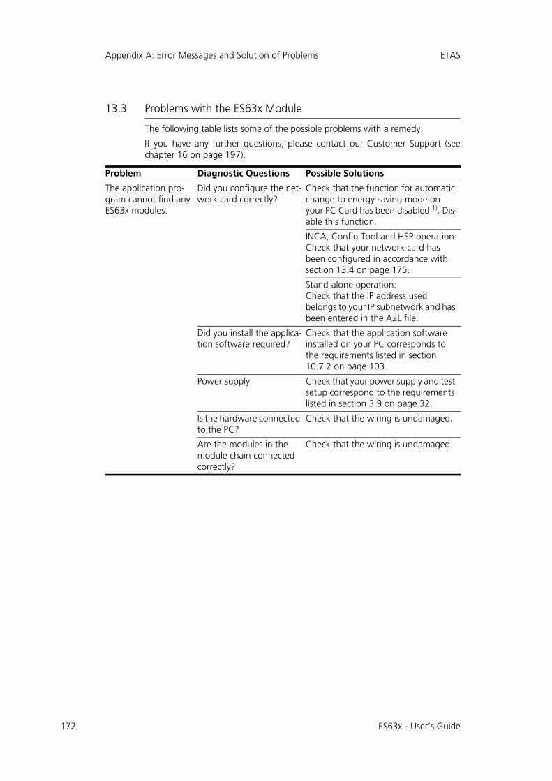
172
Appendix A: Error Messages and Solution of Problems ETAS
13.3 Problems with the ES63x Module
The following table lists some of the possible problems with a remedy.
If you have any further questions, please contact our Customer Support (seechapter 16 on page 197).
Problem Diagnostic Questions Possible Solutions
The application pro-gram cannot find any ES63x modules.
Did you configure the net-work card correctly?
Check that the function for automatic change to energy saving mode on your PC Card has been disabled 1). Dis-able this function.
INCA, Config Tool and HSP operation:Check that your network card has been configured in accordance with section 13.4 on page 175.
Stand-alone operation:Check that the IP address used belongs to your IP subnetwork and has been entered in the A2L file.
Did you install the applica-tion software required?
Check that the application software installed on your PC corresponds to the requirements listed in section 10.7.2 on page 103.
Power supply Check that your power supply and test setup correspond to the requirements listed in section 3.9 on page 32.
Is the hardware connected to the PC?
Check that the wiring is undamaged.
Are the modules in the module chain connected correctly?
Check that the wiring is undamaged.
ES63x - User’s Guide
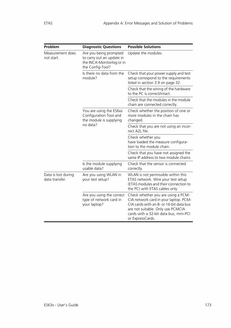
ETAS Appendix A: Error Messages and Solution of Problems
Measurement does not start.
Are you being prompted to carry out an update in the INCA-Monitorlog or in the Config-Tool?
Update the modules.
Is there no data from the module?
Check that your power supply and test setup correspond to the requirements listed in section 3.9 on page 32.
Check that the wiring of the hardware to the PC is correct/intact.
Check that the modules in the module chain are connected correctly.
You are using the ES6xx Configuration Tool and the module is supplying no data?
Check whether the position of one or more modules in the chain has changed.
Check that you are not using an incor-rect A2L file.
Check whether youhave loaded the measure configura-tion to the module chain.
Check that you have not assigned the same IP address to two module chains.
Is the module supplying usable data?
Check that the sensor is connected correctly.
Data is lost during data transfer.
Are you using WLAN in your test setup?
WLAN is not permissible within this ETAS network. Wire your test setup (ETAS modules and their connection to the PC) with ETAS cables only.
Are you using the correct type of network card in your laptop?
Check whether you are using a PCM-CIA network card in your laptop. PCM-CIA cards with an 8- or 16-bit data bus are not suitable. Only use PCMCIA cards with a 32-bit data bus, mini-PCI or ExpressCards.
Problem Diagnostic Questions Possible Solutions
ES63x - User’s Guide 173
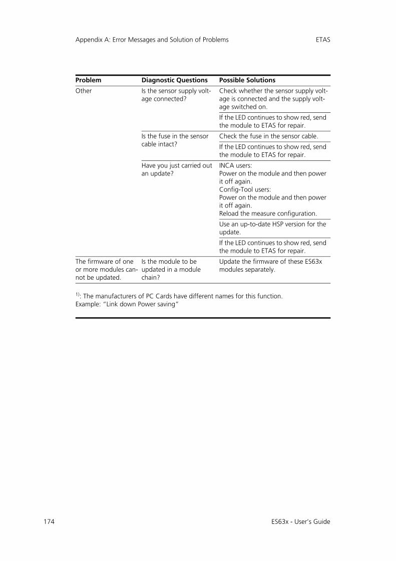
174
Appendix A: Error Messages and Solution of Problems ETAS
Other Is the sensor supply volt-age connected?
Check whether the sensor supply volt-age is connected and the supply volt-age switched on.
If the LED continues to show red, send the module to ETAS for repair.
Is the fuse in the sensor cable intact?
Check the fuse in the sensor cable.
If the LED continues to show red, send the module to ETAS for repair.
Have you just carried out an update?
INCA users:Power on the module and then power it off again.Config-Tool users:Power on the module and then power it off again.Reload the measure configuration.
Use an up-to-date HSP version for the update.
If the LED continues to show red, send the module to ETAS for repair.
The firmware of one or more modules can-not be updated.
Is the module to be updated in a module chain?
Update the firmware of these ES63x modules separately.
1): The manufacturers of PC Cards have different names for this function. Example: “Link down Power saving”
Problem Diagnostic Questions Possible Solutions
ES63x - User’s Guide
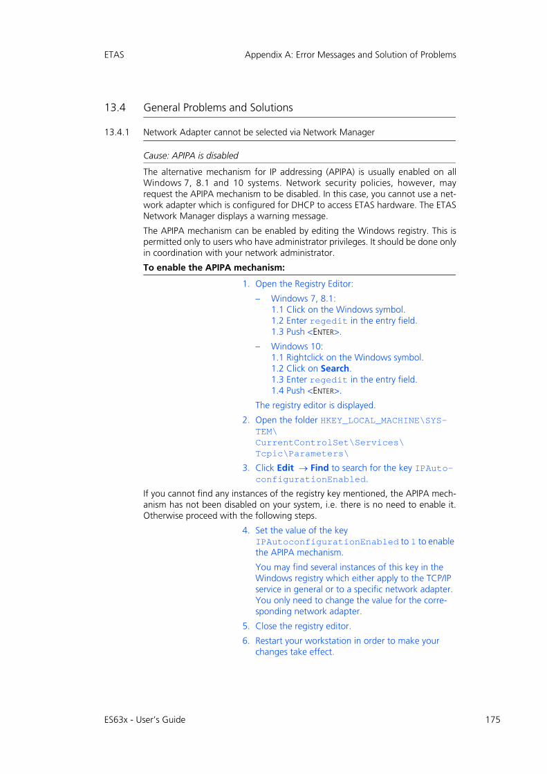
ETAS Appendix A: Error Messages and Solution of Problems
13.4 General Problems and Solutions
13.4.1 Network Adapter cannot be selected via Network Manager
Cause: APIPA is disabled
The alternative mechanism for IP addressing (APIPA) is usually enabled on allWindows 7, 8.1 and 10 systems. Network security policies, however, mayrequest the APIPA mechanism to be disabled. In this case, you cannot use a net-work adapter which is configured for DHCP to access ETAS hardware. The ETASNetwork Manager displays a warning message.
The APIPA mechanism can be enabled by editing the Windows registry. This ispermitted only to users who have administrator privileges. It should be done onlyin coordination with your network administrator.
To enable the APIPA mechanism:
1. Open the Registry Editor:
– Windows 7, 8.1:1.1 Click on the Windows symbol.1.2 Enter regedit in the entry field.1.3 Push <ENTER>.
– Windows 10:1.1 Rightclick on the Windows symbol.1.2 Click on Search.1.3 Enter regedit in the entry field.1.4 Push <ENTER>.
The registry editor is displayed.
2. Open the folder HKEY_LOCAL_MACHINE\SYS-TEM\CurrentControlSet\Services\Tcpic\Parameters\
3. Click Edit Find to search for the key IPAuto-configurationEnabled.
If you cannot find any instances of the registry key mentioned, the APIPA mech-anism has not been disabled on your system, i.e. there is no need to enable it.Otherwise proceed with the following steps.
4. Set the value of the key IPAutoconfigurationEnabled to 1 to enable the APIPA mechanism.
You may find several instances of this key in the Windows registry which either apply to the TCP/IP service in general or to a specific network adapter. You only need to change the value for the corre-sponding network adapter.
5. Close the registry editor.
6. Restart your workstation in order to make your changes take effect.
ES63x - User’s Guide 175
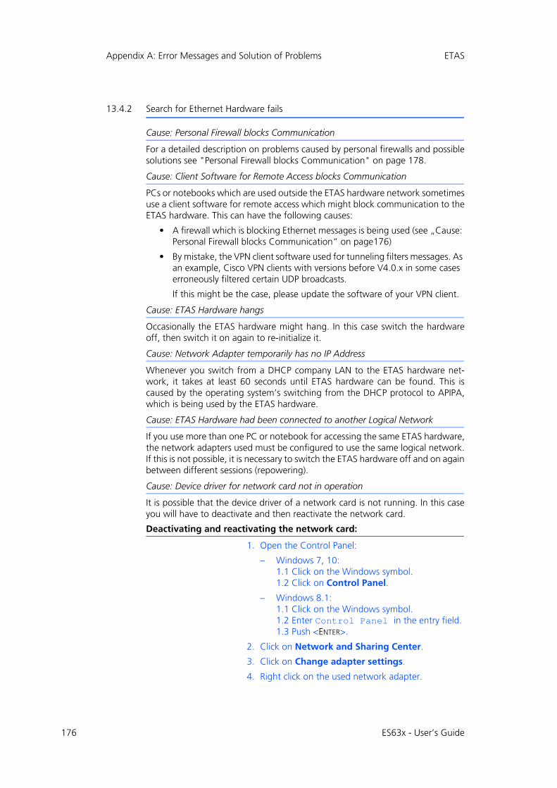
176
Appendix A: Error Messages and Solution of Problems ETAS
13.4.2 Search for Ethernet Hardware fails
Cause: Personal Firewall blocks Communication
For a detailed description on problems caused by personal firewalls and possiblesolutions see "Personal Firewall blocks Communication" on page 178.
Cause: Client Software for Remote Access blocks Communication
PCs or notebooks which are used outside the ETAS hardware network sometimesuse a client software for remote access which might block communication to theETAS hardware. This can have the following causes:
• A firewall which is blocking Ethernet messages is being used (see „Cause: Personal Firewall blocks Communication“ on page176)
• By mistake, the VPN client software used for tunneling filters messages. As an example, Cisco VPN clients with versions before V4.0.x in some cases erroneously filtered certain UDP broadcasts.
If this might be the case, please update the software of your VPN client.
Cause: ETAS Hardware hangs
Occasionally the ETAS hardware might hang. In this case switch the hardwareoff, then switch it on again to re-initialize it.
Cause: Network Adapter temporarily has no IP Address
Whenever you switch from a DHCP company LAN to the ETAS hardware net-work, it takes at least 60 seconds until ETAS hardware can be found. This iscaused by the operating system’s switching from the DHCP protocol to APIPA,which is being used by the ETAS hardware.
Cause: ETAS Hardware had been connected to another Logical Network
If you use more than one PC or notebook for accessing the same ETAS hardware,the network adapters used must be configured to use the same logical network.If this is not possible, it is necessary to switch the ETAS hardware off and on againbetween different sessions (repowering).
Cause: Device driver for network card not in operation
It is possible that the device driver of a network card is not running. In this caseyou will have to deactivate and then reactivate the network card.
Deactivating and reactivating the network card:
1. Open the Control Panel:
– Windows 7, 10:1.1 Click on the Windows symbol.1.2 Click on Control Panel.
– Windows 8.1:1.1 Click on the Windows symbol.1.2 Enter Control Panel in the entry field.1.3 Push <ENTER>.
2. Click on Network and Sharing Center.
3. Click on Change adapter settings.
4. Right click on the used network adapter.
ES63x - User’s Guide
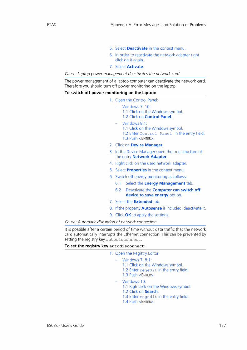
ETAS Appendix A: Error Messages and Solution of Problems
5. Select Deactivate in the context menu.
6. In order to reactivate the network adapter right click on it again.
7. Select Activate.
Cause: Laptop power management deactivates the network card
The power management of a laptop computer can deactivate the network card.Therefore you should turn off power monitoring on the laptop.
To switch off power monitoring on the laptop:
1. Open the Control Panel:
– Windows 7, 10:1.1 Click on the Windows symbol.1.2 Click on Control Panel.
– Windows 8.1:1.1 Click on the Windows symbol.1.2 Enter Control Panel in the entry field.1.3 Push <ENTER>.
2. Click on Device Manager.
3. In the Device Manager open the tree structure of the entry Network Adapter.
4. Right click on the used network adapter.
5. Select Properties in the context menu.
6. Switch off energy monitoring as follows:
6.1 Select the Energy Management tab.
6.2 Deactivate the Computer can switch off device to save energy option.
7. Select the Extended tab.
8. If the property Autosense is included, deactivate it.
9. Click OK to apply the settings.
Cause: Automatic disruption of network connection
It is possible after a certain period of time without data traffic that the networkcard automatically interrupts the Ethernet connection. This can be prevented bysetting the registry key autodisconnect.
To set the registry key autodisconnect:
1. Open the Registry Editor:
– Windows 7, 8.1:1.1 Click on the Windows symbol.1.2 Enter regedit in the entry field.1.3 Push <ENTER>.
– Windows 10:1.1 Rightclick on the Windows symbol.1.2 Click on Search.1.3 Enter regedit in the entry field.1.4 Push <ENTER>.
ES63x - User’s Guide 177
178
Appendix A: Error Messages and Solution of Problems ETAS
2. Select under HKEY_LOCAL_MACHINE\SYSTEM\ControlSet001\Services\lanmanserver\parameters the Registry Key autodiscon-nect.
3. Change its value to 0xffffffff.
13.4.3 Personal Firewall blocks Communication
Cause: Permissions given through the firewall block ETAS hardware
Personal firewalls may interfere with access to ETAS Ethernet hardware. Theautomatic search for hardware typically cannot find any Ethernet hardware at all,although the configuration parameters are correct.
Certain actions in ETAS products may lead to some trouble if the firewall is notproperly parameterized, e.g. upon opening an experiment in ASCET or searchingfor hardware from within INCA or HSP.
If a firewall is blocking communication to ETAS hardware, you must either disablethe firewall software while working with ETAS software, or the firewall must beconfigured to give the following permissions:
• Outgoing limited IP broadcasts via UDP (destination address 255.255.255.255) for destination port 18001
• Incoming limited IP broadcasts via UDP (destination IP 255.255.255.255, originating from source IP 0.0.0.0) for destination port 18001
• Directed IP broadcasts via UDP to the network configured for the ETAS application, destination port 18001
• Outgoing IP unicasts via UDP to any IP in network configured for the ETAS application, destination ports 69, 18001, 18017 or 49152 to 50175
• Incoming IP unicasts via UDP originating from any IP in the network con-figured for the ETAS application, source ports 69, 18001, 18017 or 49152 to 50175
Windows 7, 8.1 and 10 come with a built-in personal firewall. On many othersystems it is very common to have personal firewall software from third partyvendors, such as Symantec, McAffee or BlackIce installed. The proceedings inconfiguring the ports might differ for each personal firewall software used.Therefore please refer to the user documentation of your personal firewall soft-ware for further details.
As an example for a firewall configuration, you will find below a description onhow to configure the widely used Windows firewall if the hardware access isprohibited under Windows.
Note
The ports that have to be used in concrete use cases depend on the hardware used. For more precise information on the port numbers that can be used please refer to your hardware docu-mentation.
ES63x - User’s Guide
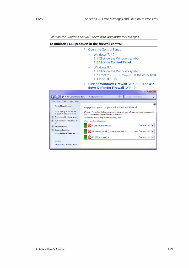
ETAS Appendix A: Error Messages and Solution of Problems
Solution for Windows Firewall, Users with Administrator Privileges
To unblock ETAS products in the firewall control:
1. Open the Control Panel:
– Windows 7, 10:1.1 Click on the Windows symbol.1.2 Click on Control Panel.
– Windows 8.1:1.1 Click on the Windows symbol.1.2 Enter Control Panel in the entry field.1.3 Push <ENTER>.
2. Click on Windows Firewall (Win 7, 8.1) or Win-dows Defender Firewall (Win 10).
ES63x - User’s Guide 179

180
Appendix A: Error Messages and Solution of Problems ETAS
3. Click on Allow a program / app or feature through Windows (Defender) Firewall.
This window lists the exceptions that are not blocked by the firewall.
4. Click on Change settings.
5. Check the boxes to enable the respective program for the corresponding network.
6. Ensure that the ETAS products and services to be used are correctly configured exceptions.
7. Klick on OK.
8. Close the Windows Firewall.
The firewall no longer blocks the ETAS product. The setting is retained after a restart of the PC.
ES63x - User’s Guide
ETAS Appendix A: Error Messages and Solution of Problems
Solution for Windows Firewall, Users without Administrator Privileges
This section addresses users with restricted privileges, e.g., no system changes,write restrictions, local login.
Working with an ETAS software product requires "Write" and "Modify" privi-leges within the ETAS, ETASData, and ETAS temporary directories. Otherwise,an error message opens if the product is started, and a database is opened. Inthat case, no correct operation of the ETAS product is possible because the data-base file and some *.ini files are modified during operation.
The ETAS software has to be installed by an administrator anyway. It is recom-mended that the administrator assures that the ETAS program/processes areadded to the list of the Windows XP firewall exceptions, and selected in that list,after the installation.
ES63x - User’s Guide 181
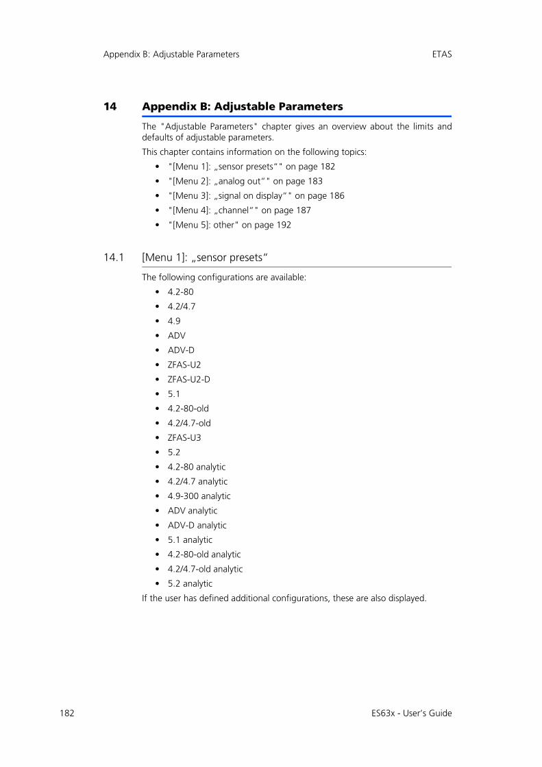
182
Appendix B: Adjustable Parameters ETAS
14 Appendix B: Adjustable Parameters
The "Adjustable Parameters" chapter gives an overview about the limits anddefaults of adjustable parameters.
This chapter contains information on the following topics:
• "[Menu 1]: „sensor presets“" on page 182
• "[Menu 2]: „analog out“" on page 183
• "[Menu 3]: „signal on display“" on page 186
• "[Menu 4]: „channel“" on page 187
• "[Menu 5]: other" on page 192
14.1 [Menu 1]: „sensor presets“
The following configurations are available:
• 4.2-80
• 4.2/4.7
• 4.9
• ADV
• ADV-D
• ZFAS-U2
• ZFAS-U2-D
• 5.1
• 4.2-80-old
• 4.2/4.7-old
• ZFAS-U3
• 5.2
• 4.2-80 analytic
• 4.2/4.7 analytic
• 4.9-300 analytic
• ADV analytic
• ADV-D analytic
• 5.1 analytic
• 4.2-80-old analytic
• 4.2/4.7-old analytic
• 5.2 analytic
If the user has defined additional configurations, these are also displayed.
ES63x - User’s Guide
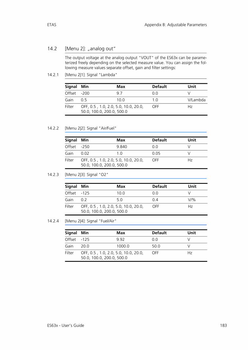
ETAS Appendix B: Adjustable Parameters
14.2 [Menu 2]: „analog out“
The output voltage at the analog output "VOUT" of the ES63x can be parame-terized freely depending on the selected measure value. You can assign the fol-lowing measure values separate offset, gain and filter settings:
14.2.1 [Menu 2|1]: Signal "Lambda"
14.2.2 [Menu 2|2]: Signal "Air/Fuel"
14.2.3 [Menu 2|3]: Signal "O2"
14.2.4 [Menu 2|4]: Signal "Fuel/Air"
Signal Min Max Default Unit
Offset -200 9.7 0.0 V
Gain 0.5 10.0 1.0 V/Lambda
Filter OFF, 0.5 , 1.0, 2.0, 5.0, 10.0, 20.0, 50.0, 100.0, 200.0, 500.0
OFF Hz
Signal Min Max Default Unit
Offset -250 9.840 0.0 V
Gain 0.02 1.0 0.05 V
Filter OFF, 0.5 , 1.0, 2.0, 5.0, 10.0, 20.0, 50.0, 100.0, 200.0, 500.0
OFF Hz
Signal Min Max Default Unit
Offset -125 10.0 0.0 V
Gain 0.2 5.0 0.4 V/%
Filter OFF, 0.5 , 1.0, 2.0, 5.0, 10.0, 20.0, 50.0, 100.0, 200.0, 500.0
OFF Hz
Signal Min Max Default Unit
Offset -125 9.92 0.0 V
Gain 20.0 1000.0 50.0 V
Filter OFF, 0.5 , 1.0, 2.0, 5.0, 10.0, 20.0, 50.0, 100.0, 200.0, 500.0
OFF Hz
ES63x - User’s Guide 183

184
Appendix B: Adjustable Parameters ETAS
14.2.5 [Menu 2|5]: Signal "1 / Lambda"
14.2.6 [Menu 2|6]: Signal "Ip"
14.2.7 [Menu 2|7]: Signal "Ri"
14.2.8 [Menu 2|8] : Signal "Uh"
14.2.9 [Menu 2|9]: Signal "Ih"
Signal Min Max Default Unit
Offset -80 9.9 0.0 V
Gain 2.0 50.0 5.0 V*Lambda
Filter OFF, 0.5 , 1.0, 2.0, 5.0, 10.0, 20.0, 50.0, 100.0, 200.0, 500.0
OFF Hz
Signal Min Max Default Unit
Offset -100.0 110.0 5.0 V
Gain 0.2 10.0 0.5 V/mA
Filter OFF, 0.5 , 1.0, 2.0, 5.0, 10.0, 20.0, 50.0, 100.0, 200.0, 500.0
OFF Hz
Signal Min Max Default Unit
Offset -1000.0 10.0 0.0 V
Gain 0.002 0.5 0.005 V/Ohm
Filter OFF, 0.5 , 1.0, 2.0, 5.0, 10.0 OFF Hz
Signal Min Max Default Unit
Offset -90.0 10.0 0.0 V
Gain 0.2 5.0 0.5 V/V
Filter OFF, 0.5 , 1.0, 2.0, 5.0, 10.0 OFF Hz
Signal Min Max Default Unit
Offset -200.0 10.0 0.0 V
Gain 1.0 20.0 2.0 V/A
Filter OFF, 0.5 , 1.0, 2.0, 5.0, 10.0 OFF Hz
ES63x - User’s Guide

ETAS Appendix B: Adjustable Parameters
14.2.10 [Menu 2|10]: Signal "Unernst"
14.2.11 [Menu 2|11]: Signal "Upump"
14.2.12 [Menu 2|12]: Signal "T"
14.2.13 [Menu 2|13]: Signal "pamb"
14.2.14 [Menu 2|14]: Signal "pex" (ES635.1 and ES636.1 only)
Signal Min Max Default Unit
Offset -1000.0 10.0 0.0 V
Gain 5.0 1000.0 10.0 V/V
Filter OFF, 0.5 , 1.0, 2.0, 5.0, 10.0, 20.0, 50.0, 100.0, 200.0, 500.0
OFF Hz
Signal Min Max Default Unit
Offset -80.0 90.0 5.0 V
Gain 0.5 20.0 1.0 V/V
Filter OFF, 0.5 , 1.0, 2.0, 5.0, 10.0, 20.0, 50.0, 100.0, 200.0, 500.0
OFF Hz
Signal Min Max Default Unit
Offset -100.0 8.0 -5.0 V
Gain 0.005 0.1 0.01 V/°C
Filter OFF, 0.5 , 1.0, 2.0, 5.0, 10.0 OFF Hz
Signal Min Max Default Unit
Offset -115.0 7.0 -5.0 V
Gain 0.005 0.1 0.01 V/hPa
Filter OFF OFF Hz
Signal Min Max Default Unit
Offset -250.0 10.0 0.0 V
Gain 0.001 0.05 0.002 V/hPa
Filter OFF, 0.5 , 1.0, 2.0, 5.0, 10.0, 20.0, 50.0, 100.0, 200.0, 500.0
OFF Hz
ES63x - User’s Guide 185

186
Appendix B: Adjustable Parameters ETAS
14.3 [Menu 3]: „signal on display“
Symbol Signal
l Lambda
A/F Air to fuel ratio
O2 O2 concentration
F/A Fuel to air ratio
1/ Reciprocal Lambda
Ip Pump current
Ri Sensor resistance
Uh Heater voltage
Ih Heater current
Un Nernst voltage
Up Pump voltage
T Sensor temperature
pa Ambient pressure
pex Pressure from external pressure sensor (ES635.1 and ES636.1 only)
Fr Filling level of reservoir (only applicable to the LSU5.1)
Sta State/ operational state of the sensor
OFF Display off (ES631.1/ ES636.1: CH1/ CH2 separately)
ES63x - User’s Guide
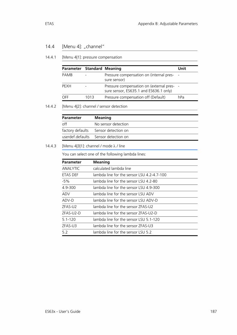
ETAS Appendix B: Adjustable Parameters
14.4 [Menu 4]: „channel“
14.4.1 [Menu 4|1]: pressure compensation
14.4.2 [Menu 4|2]: channel / sensor detection
14.4.3 [Menu 4|3|1]: channel / mode / line
You can select one of the following lambda lines:
Parameter Standard Meaning Unit
PAMB - Pressure compensation on (internal pres-sure sensor)
-
PEXH - Pressure compensation on (external pres-sure sensor, ES635.1 and ES636.1 only)
-
OFF 1013 Pressure compensation off (Default) hPa
Parameter Meaning
off No sensor detection
factory defaults Sensor detection on
userdef.defaults Sensor detection on
Parameter Meaning
ANALYTIC calculated lambda line
ETAS DEF lambda line for the sensor LSU 4.2-4.7-100
-5% lambda line for the sensor LSU 4.2-80
4.9-300 lambda line for the sensor LSU 4.9-300
ADV lambda line for the sensor LSU ADV
ADV-D lambda line for the sensor LSU ADV-D
ZFAS-U2 lambda line for the sensor ZFAS-U2
ZFAS-U2-D lambda line for the sensor ZFAS-U2-D
5.1-120 lambda line for the sensor LSU 5.1-120
ZFAS-U3 lambda line for the sensor ZFAS-U3
5.2 lambda line for the sensor LSU 5.2
ES63x - User’s Guide 187

188
Appendix B: Adjustable Parameters ETAS
14.4.4 [Menu 4|3|2]: channel / mode / analytic
[Menu 4|3|2|1]: fuel
[Menu 4|3|2|2]: climatic conditions
14.4.5 [Menu 4|3|3]: channel / mode / advanced
[Menu 4|3|3|1]: H2-Shift
[Menu 4|3|3|2]: LSU calibration
The module can be calibrated to the characteristic of a connected sensor by dif-ferent methods:
1. manual input (submenu "Input")
2. calibration by measuring in a lean or in a rich gas as well as in a reference gas (submenu "Ref. gas / lean ref.", "Ref. gas / rich ref." and "Ref. gas / zero ref."; for detailled information refer to chapter 8.2.3 on page 80).
Parameter Min Max Default Meaning Unit
H/C 1.0 4.0 1.850 Ratio of hydrogen/carbon
mol/mol
O/C 0.0 1.0 0.0 Ratio of oxygen/carbon
mol/mol
H2O 0.0 100.0 0.0 Water proportion mmol/mol
AFSt. 6.0 20.0 14.7 Stoichiometric ratio
kg/kg
Parameter Min Max Default Meaning Unit
Humidity 0.0 100.0 40.0 Relative humidity %
Air Temp. -20.0 70.0 23.0 Air temperature °C
Parameter Min Max Default Meaning Unit
lower th 0.9 0.98 0.98 Lower limit H2 shift
-
at Ip=0 1.0 1.1019 1.009 Mean H2 shift -
upper th 1.02 1.1 1.05 Upper limit H2 shift
-
ES63x - User’s Guide
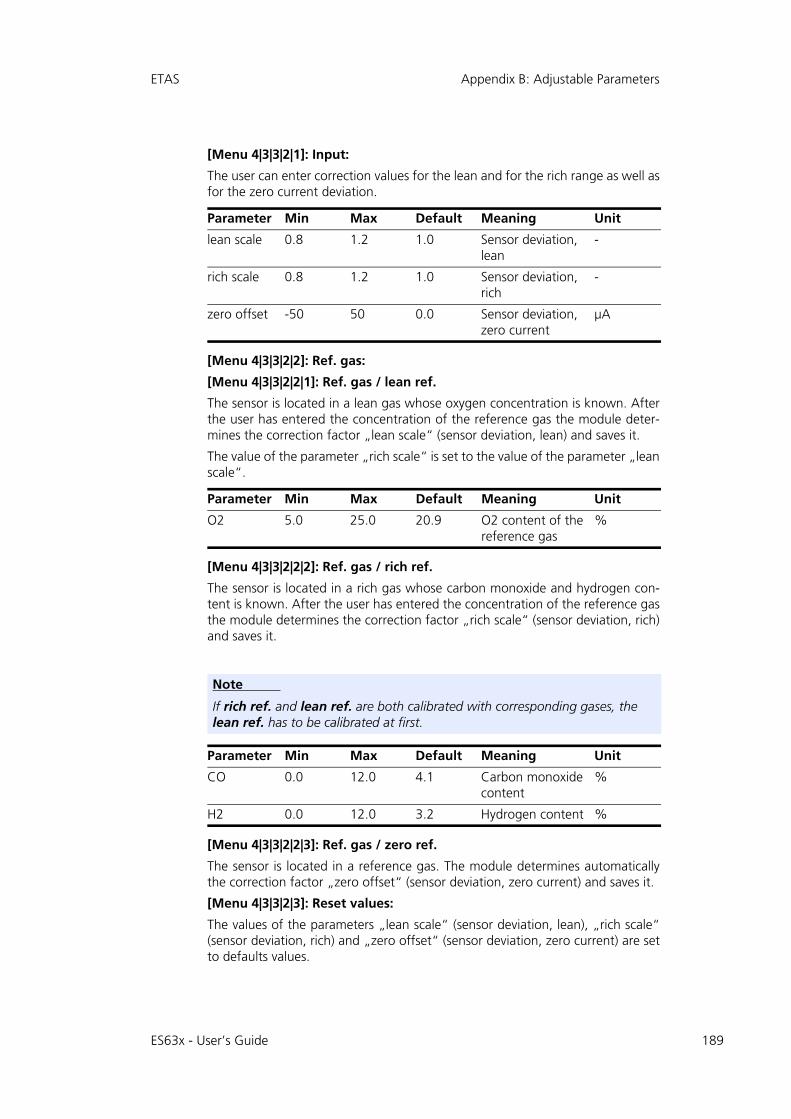
ETAS Appendix B: Adjustable Parameters
[Menu 4|3|3|2|1]: Input:
The user can enter correction values for the lean and for the rich range as well asfor the zero current deviation.
[Menu 4|3|3|2|2]: Ref. gas:
[Menu 4|3|3|2|2|1]: Ref. gas / lean ref.
The sensor is located in a lean gas whose oxygen concentration is known. Afterthe user has entered the concentration of the reference gas the module deter-mines the correction factor „lean scale“ (sensor deviation, lean) and saves it.
The value of the parameter „rich scale“ is set to the value of the parameter „leanscale“.
[Menu 4|3|3|2|2|2]: Ref. gas / rich ref.
The sensor is located in a rich gas whose carbon monoxide and hydrogen con-tent is known. After the user has entered the concentration of the reference gasthe module determines the correction factor „rich scale“ (sensor deviation, rich)and saves it.
[Menu 4|3|3|2|2|3]: Ref. gas / zero ref.
The sensor is located in a reference gas. The module determines automaticallythe correction factor „zero offset“ (sensor deviation, zero current) and saves it.
[Menu 4|3|3|2|3]: Reset values:
The values of the parameters „lean scale“ (sensor deviation, lean), „rich scale“(sensor deviation, rich) and „zero offset“ (sensor deviation, zero current) are setto defaults values.
Parameter Min Max Default Meaning Unit
lean scale 0.8 1.2 1.0 Sensor deviation, lean
-
rich scale 0.8 1.2 1.0 Sensor deviation, rich
-
zero offset -50 50 0.0 Sensor deviation, zero current
μA
Parameter Min Max Default Meaning Unit
O2 5.0 25.0 20.9 O2 content of the reference gas
%
Note
If rich ref. and lean ref. are both calibrated with corresponding gases, the lean ref. has to be calibrated at first.
Parameter Min Max Default Meaning Unit
CO 0.0 12.0 4.1 Carbon monoxide content
%
H2 0.0 12.0 3.2 Hydrogen content %
ES63x - User’s Guide 189

190
Appendix B: Adjustable Parameters ETAS
[Menu 4|3|3|3]: TDET
14.4.6 [Menu 4|4]: channel / heater line
14.4.7 [Menu 4|5]: channel / temperature line
Parameter Min Max Default Meaning Unit
TDET 200.0 2000.0 1212.0 Water gas equilib-rium temperature
°C
Parameter Meaning
ETAS DEF Heater line for the sensors LSU 4.2-80 and LSU 4.2-4.7-100
HtUp-300 Heater line for the sensor LSU 4.9-300
ADV Heater line for the sensor LSU ADV
ZFAS-U2/D Heater line for the sensors ZFAS-U2 and ZFAS-D
HtUp-5.1 Heater line for the sensor LSU 5.1
HtUp-4.2 Heater line for the sensors LSU 4.2-80 and LSU 4.2-4.7-100
ZFAS-U3 Heater line for the sensor ZFAS-U3
HtUp-5.2 Heater line for the sensor LSU 5.2
Parameter Meaning
T-4.2-100 Temperature line for the sensor LSU 4.2-4.7-100
T-4.2-80 Temperature line for the sensor LSU 4.2-80
T-4.9-300 Temperature line for the sensor LSU 4.9-300
T-ADV Temperature line for the sensor LSU ADV
T-ADV-D Temperature line for the sensor LSU ADV-D
T-ZFAS-U2/D Temperature line for the sensors ZFAS-U2 and ZFAS-D
T-5.1-120 Temperature line for the sensor LSU 5.1
T-ZFAS-U3 Temperature line for the sensor ZFAS-U3
T-5.2 Temperature line for the sensor LSU 5.2
ES63x - User’s Guide
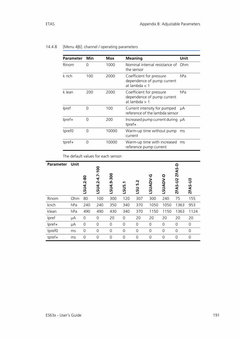
ETAS Appendix B: Adjustable Parameters
14.4.8 [Menu 4|6]: channel / operating parameters
The default values for each sensor:
Parameter Min Max Meaning Unit
Rinom 0 1000 Nominal internal resistance of the sensor
Ohm
k rich 100 2000 Coefficient for pressure dependence of pump current at lambda < 1
hPa
k lean 200 2000 Coefficient for pressure dependence of pump current at lambda > 1
hPa
Ipref 0 100 Current intensity for pumped reference of the lambda sensor
μA
Ipref+ 0 200 Increased pump current during tpref+
μA
tpref0 0 10000 Warm-up time without pump current
ms
tpref+ 0 10000 Warm-up time with increased reference pump current
ms
Parameter Unit
LSU
4.2-
80
LSU
4.2-
4.7-
100
LSU
4.9-
300
LSU
5.1
LSU
5.2
LSU
AD
V-G
LSU
AD
V-D
ZFA
S-U
2 ZF
AS-
D
ZFA
S-U
3
Rinom Ohm 80 100 300 120 307 300 240 75 155
krich hPa 240 240 350 340 370 1050 1050 1363 953
klean hPa 490 490 430 340 370 1150 1150 1363 1124
Ipref μA 0 0 20 0 20 20 20 20 20
Ipref+ μA 0 0 0 0 0 0 0 0 0
tpref0 ms 0 0 0 0 0 0 0 0 0
tpref+ ms 0 0 0 0 0 0 0 0 0
ES63x - User’s Guide 191
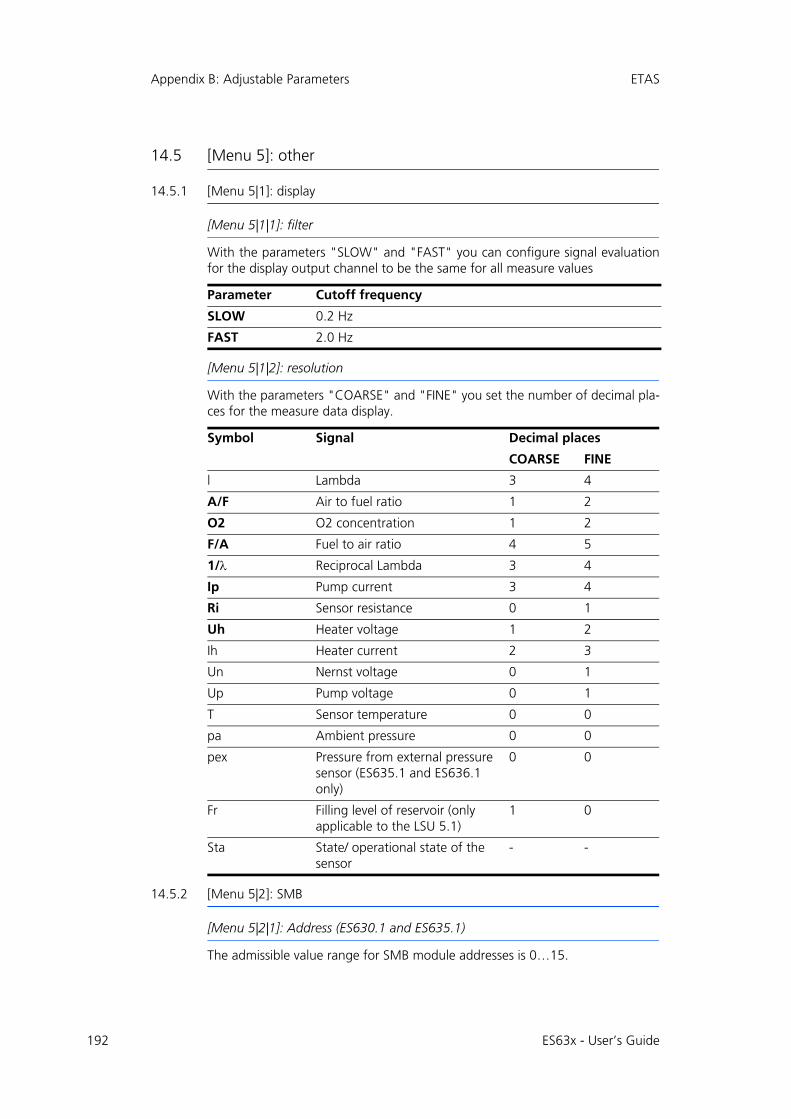
192
Appendix B: Adjustable Parameters ETAS
14.5 [Menu 5]: other
14.5.1 [Menu 5|1]: display
[Menu 5|1|1]: filter
With the parameters "SLOW" and "FAST" you can configure signal evaluationfor the display output channel to be the same for all measure values
[Menu 5|1|2]: resolution
With the parameters "COARSE" and "FINE" you set the number of decimal pla-ces for the measure data display.
14.5.2 [Menu 5|2]: SMB
[Menu 5|2|1]: Address (ES630.1 and ES635.1)
The admissible value range for SMB module addresses is 0…15.
Parameter Cutoff frequency
SLOW 0.2 Hz
FAST 2.0 Hz
Symbol Signal Decimal places
COARSE FINE
l Lambda 3 4
A/F Air to fuel ratio 1 2
O2 O2 concentration 1 2
F/A Fuel to air ratio 4 5
1/ Reciprocal Lambda 3 4
Ip Pump current 3 4
Ri Sensor resistance 0 1
Uh Heater voltage 1 2
Ih Heater current 2 3
Un Nernst voltage 0 1
Up Pump voltage 0 1
T Sensor temperature 0 0
pa Ambient pressure 0 0
pex Pressure from external pressure sensor (ES635.1 and ES636.1 only)
0 0
Fr Filling level of reservoir (only applicable to the LSU 5.1)
1 0
Sta State/ operational state of the sensor
- -
ES63x - User’s Guide

ETAS Appendix B: Adjustable Parameters
[Menu 5|2|2]: filter (ES630.1 and ES635.1)
You can assign a filter value to the following measure values to smooth the mea-sure result:
[Menu 5|2|1]: CH1 address (ES631.1 and ES636.1)
An individual module address must be assigned to each measurement channel ofeach module when several SMB modules are connected.
The admissible value range for SMB module addresses is 0…15.
[Menu 5|2|2]: CH1 filter (ES631.1 and ES636.1)
You can assign a filter value to the following measure values to smooth the mea-sure result:
Signal Possible Values Default Unit
Lambda OFF, 2, 5, 10, 20, 50, 100, 200, 500, 1000, 2000
20 ms
Ri OFF, 100, 200, 500, 1000, 2000 OFF ms
O2 OFF, 2, 5, 10, 20, 50, 100, 200, 500, 1000, 2000
20 ms
A/F OFF, 2, 5, 10, 20, 50, 100, 200, 500, 1000, 2000
20 ms
Ip 50, 100, 200, 500, 1000, 2000 10 ms
Signal Meaning Min Max Invalid Value
Unit
Lambda Byte Lambda 0.74 1.76 0.74 -
Lambda Word Lambda 0.7 32.767 0.0 -
Air/Fuel Word Air to fuel ratio 10.29 327.67 0.0 -
O2 word O2 concentration 0.0 24.41 0.0 %
Ip Word Pump current -3.0 3.0 0.0 mA
Ri word Sensor resistance 0.0 500.0 0.0 Ohms
Signal Possible Values Default Unit
Lambda OFF, 2, 5, 10, 20, 50, 100, 200, 500, 1000, 2000
20 ms
Ri OFF, 100, 200, 500, 1000, 2000 OFF ms
O2 OFF, 2, 5, 10, 20, 50, 100, 200, 500, 1000, 2000
20 ms
A/F OFF, 2, 5, 10, 20, 50, 100, 200, 500, 1000, 2000
20 ms
Ip 50, 100, 200, 500, 1000, 2000 10 ms
ES63x - User’s Guide 193

194
Appendix B: Adjustable Parameters ETAS
[Menu 5|2|3]: CH2 address (ES631.1 and ES636.1)
An individual module address must be assigned to each measurement channel ofeach module when several SMB modules are connected.
The admissible value range for SMB module addresses is 0…15.
[Menu 5|2|4]: CH2 filter (ES631.1 and ES636.1)
You can assign a filter value to the following measure values to smooth the mea-sure result:
14.5.3 [Menu 5|3]: device mode
You can choose between the opreating modes “Standard” and “Advanced” ofthe ES63x.
Signal Meaning Min Max Invalid Value
Unit
Lambda Byte Lambda 0.74 1.76 0.74 -
Lambda Word Lambda 0.7 32.767 0.0 -
Air/Fuel Word Air to fuel ratio 10.29 327.67 0.0 -
O2 word O2 concentration 0.0 24.41 0.0 %
Ip Word Pump current -3.0 3.0 0.0 mA
Ri word Sensor resistance 0.0 500.0 0.0 Ohms
Signal Possible Values Default Unit
Lambda OFF, 2, 5, 10, 20, 50, 100, 200, 500, 1000, 2000
20 ms
Ri OFF, 100, 200, 500, 1000, 2000 OFF ms
O2 OFF, 2, 5, 10, 20, 50, 100, 200, 500, 1000, 2000
20 ms
A/F OFF, 2, 5, 10, 20, 50, 100, 200, 500, 1000, 2000
20 ms
Ip 50, 100, 200, 500, 1000, 2000 10 ms
Signal Meaning Min Max Invalid Value
Unit
Lambda Byte Lambda 0.74 1.76 0.74 -
Lambda Word Lambda 0.7 32.767 0.0 -
Air/Fuel Word Air to fuel ratio 10.29 327.67 0.0 -
O2 word O2 concentration 0.0 24.41 0.0 %
Ip Word Pump current -3.0 3.0 0.0 mA
Ri word Sensor resistance 0.0 500.0 0.0 Ohms
ES63x - User’s Guide
ETAS Appendix B: Adjustable Parameters
14.5.4 [Menu 5|4]: factory init
You can reset the settings of the module to their default configuration if thefactory default configurations of the module have been changed.
14.5.5 [Menu 5|5] : version
Information on the firmware, the serial number,the IP address and the netmaskis displayed simultaneously.
ES63x - User’s Guide 195

ES63x - User’s Guide196
Appendix C: Configuration Menu ETAS
15 Appendix C: Configuration Menu
ES63x - User’s Guide 197
ETAS ETAS Contact Addresses
16 ETAS Contact Addresses
ETAS HQ
ETAS GmbH
ETAS Subsidiaries and Technical Support
For details of your local sales office as well as your local technical support teamand product hotlines, take a look at the ETAS website:
Borsigstraße 24 Phone: +49 711 3423-0
70469 Stuttgart Fax: +49 711 3423-2106
Germany WWW: www.etas.com
ETAS subsidiaries WWW: www.etas.com/en/contact.php
ETAS technical support WWW: www.etas.com/en/hotlines.php
ETAS Figures
Figures
Fig. 3-1 ES636.1 Lambda Module............................................................................ 17Fig. 3-2 Front of Devices.......................................................................................... 20Fig. 3-3 Rear of the ES630.1 (top) and of the ES631.1 module (bottom) ................. 21Fig. 3-4 Rear of the ES635.1 (top) and of the ES636.1 (bottom) module ................. 22Fig. 3-5 Block Diagram (one Measurement Channel) ............................................... 24Fig. 3-6 Message Format “XCP on UDP” (Schematic)............................................... 27Fig. 3-7 Time-Multiplex Data Transfer Between an ES400/ES63x Module Chain and aPC .............................................................................................................. 30Fig. 3-8 Transfer Scheme for Example 1 (Simplified, Not True to Scale) .................... 30Fig. 3-9 Time-Multiplex Data Transfer Between an ES400/ES63x Module Chain and a
PC .............................................................................................................. 31Fig. 3-10 Transfer Scheme for Example 2 (Simplified, Not True to Scale) .................... 31Fig. 5-1 Prying off the plastic foot............................................................................ 41Fig. 5-2 Threaded blind hole .................................................................................. 41Fig. 5-3 Connecting the Lambda Module with another module ............................... 42Fig. 5-4 Angle of Installation.................................................................................... 44Fig. 5-5 Installation of the Lambda Sensor ............................................................... 45Fig. 5-6 Thermally Isolated Assembly of the Pressure Sensor .................................... 46Fig. 5-7 Application with ES63x Modules, ES600 Measurement Modules and INCA . 48Fig. 5-8 Application with ES63x Modules, ES4xx/ES720/ES910 and INCA................. 49Fig. 5-9 Application with ES63x Modules, ES4xx/ES720/ES910 and INTECRIO .......... 50Fig. 5-10 Power Supply to ES63x Modules linked by Ethernet .................................... 51Fig. 5-11 Power Supply to ES63x Modules linked by SMB .......................................... 52Fig. 6-1 Areas of the Display.................................................................................... 57Fig. 8-1 How to Correct Hydrogen Shift................................................................... 81Fig. 8-2 Saturation Vapor Pressure of Dry Air ........................................................... 84Fig. 9-1 Setup for measuring ambient air................................................................. 90Fig. 9-2 Setup for measuring reference gas.............................................................. 90
ES63x - User’s Guide 198
199
Figures ETAS
Fig. 9-3 Setup for measuring CO gas ....................................................................... 91Fig. 9-4 Setup for measuring zero current range...................................................... 92Fig. 10-1 WEEE Symbol ........................................................................................... 101Fig. 10-2 „IN“ Connecor ......................................................................................... 112Fig. 10-3 „OUT“ Connector .................................................................................... 113Fig. 10-4 „Sensor“ Connector ................................................................................. 114Fig. 10-5 „Analog“ Connector ................................................................................ 115Fig. 10-6 „EPS“ Connector...................................................................................... 115Fig. 11-1 CBP630-2 Cable ....................................................................................... 117Fig. 11-2 CBP6305-2 Cable ..................................................................................... 118Fig. 11-3 CBEP410.1 Cable...................................................................................... 120Fig. 11-4 CBEP4105.1 Cable.................................................................................... 120Fig. 11-5 CBEP415.1 Cable...................................................................................... 121Fig. 11-6 CBEP4155.1 Cable.................................................................................... 121Fig. 11-7 CBEP420.1 Cable...................................................................................... 122Fig. 11-8 CBEP4205.1 Cable.................................................................................... 122Fig. 11-9 CBEP425.1 Cable...................................................................................... 123Fig. 11-10 CBEP4255.1 Cable.................................................................................... 123Fig. 11-11 CBEP430.1 Cable...................................................................................... 124Fig. 11-12 CBEP4305.1 Cable.................................................................................... 124Fig. 11-13 CBE400.2 Cable ....................................................................................... 125Fig. 11-14 CBE401.1 Cable ....................................................................................... 125Fig. 11-15 CBE430.1 Cable ....................................................................................... 126Fig. 11-16 CBE431.1 Cable ....................................................................................... 126Fig. 11-17 CBEX400.1 Cable ..................................................................................... 126Fig. 11-18 K38 Cable ............................................................................................... 127Fig. 11-19 K39 Cable ............................................................................................... 127Fig. 11-20 K40 Cable ............................................................................................... 128Fig. 11-21 CBAS100 Cable ....................................................................................... 128Fig. 11-22 CBAL410.1 Cable ..................................................................................... 131Fig. 11-23 RB130fl Sensor Plug (Code 1) .................................................................. 132Fig. 11-24 BNC Socket for Analog Output Signals ..................................................... 132Fig. 11-25 CBAL4105.1 Cable ................................................................................... 133Fig. 11-26 RB130fl Sensor Plug (Code 1) .................................................................. 134Fig. 11-27 BNC Socket for Analog Output Signals ..................................................... 134Fig. 11-28 CBAL451.1 Cable ..................................................................................... 135Fig. 11-29 RB150 Sensor Plug (Code 1) .................................................................... 136Fig. 11-30 BNC Socket for Analog Output Signals ..................................................... 136Fig. 11-31 CBAL4515.1 Cable ................................................................................... 137Fig. 11-32 RB150 Sensor Plug (Code 1) .................................................................... 138Fig. 11-33 BNC Socket for Analog Output Signals ..................................................... 138Fig. 11-34 CBAL452.1 Cable ..................................................................................... 139Fig. 11-35 RB150 Sensor Plug (Code 1) .................................................................... 140Fig. 11-36 CBAL4525.1 Cable ................................................................................... 141Fig. 11-37 RB150 Sensor Plug (Code 1) .................................................................... 142Fig. 11-38 CBAL463.1 Cable ..................................................................................... 143Fig. 11-39 Trapezoid Plug (Code A7) ........................................................................ 144Fig. 11-40 BNC Socket for Analog Output Signals ..................................................... 144
ES63x - User’s Guide
ETAS Figures
Fig. 11-41 CBAL4635.1 Cable ................................................................................... 145Fig. 11-42 Trapezoid Plug (Code A7) ........................................................................ 146Fig. 11-43 BNC Socket for Analog Output Signals ..................................................... 146Fig. 11-44 CBAL468.1 Cable ..................................................................................... 147Fig. 11-45 RB150 Sensor Plug (Code 2) ..................................................................... 147Fig. 11-46 BNC Socket for Analog Output Signals ..................................................... 148Fig. 11-47 CBAL4685.1 Cable ................................................................................... 149Fig. 11-48 RB150 Sensor Plug (Code 2) ..................................................................... 149Fig. 11-49 BNC Socket for Analog Output Signals ..................................................... 150Fig. 11-50 CBAL472.1 Cable ..................................................................................... 151Fig. 11-51 RB150 Sensor Plug (Code 1 NTK) ............................................................. 152Fig. 11-52 CBAL4725.1 Cable ................................................................................... 153Fig. 11-53 RB150 Sensor Plug (Code 1 NTK) ............................................................. 154Fig. 11-54 Pressure Sensor PS63 ................................................................................ 155Fig. 11-55 CBAX100.1 Cable..................................................................................... 155Fig. 11-56 Cap CAP_LEMO_1B.................................................................................. 156Fig. 11-57 Cap CAP_LEMO_1B_LC............................................................................ 157Fig. 11-58 Cap CAP_SOURIAU_8STA......................................................................... 157
ES63x - User’s Guide 200

ETAS Index
Index
Symbols“Configuration” mode 59“EPS” port 23“IN” connector 112“LAMBDA” Port 54“LAMBDA” port 23“Measuring” mode 57“OUT” connector 113“Sensor” connector 114“VOUT” port 23„Analog“ Connector 115„EPS“ Connector 115„SERVICE“ Connector 115AAccessories 117, 163Accident prevention 12Activating measurement 64, 76Activating menu operation 64, 76Adjusting the display 58Air reference 93Air/fuel ratio
setting the default value 79Analog output 26
A/F in stoich. range 95calculation examples 94checking the sensor installation
point 94configuration 95default setting 94gain 66high-resolution measurement 95measuring oxygen concentration
up to air 95offset 66setting filter 70smooth signal 70
Analytical calculationsetting air pressure 79setting humidity 80setting the temperature 80
BBinary counter 28Block diagram 24BNC Socket 132, 134, 136, 138, 144,
146Bosch, Technical Customer Informa-
tionLSU 4.7/ LSU 4.2 43LSU 4.9 43LSU ADV 43LSU5.1 43
Broadband lambda sensor 35
ES63x - User’s Guide 201

202
Index ETAS
CCable 117
CBAL410.1 131CBAL4105.1 133CBAL411.1 135CBAL451.1 135CBAL4515.1 137CBAL452.1 139CBAL4525.1 141CBAL455.1 143CBAL463.1 143CBAL4635.1 145CBAL468.1 147CBAL4685.1 149CBAL472.1 151CBAL4725.1 153CBAS100 128CBAX100.1 155CBE400.2 125CBE401.1 125CBE430.1 126CBE431.1 126CBEP410.1 120CBEP4105.1 120CBEP415.1 121CBEP4155.1 121CBEP420.1 122CBEP4205.1 122CBEP425.1 123CBEP4255.1 123CBEP430.1 124CBEP4305.1 124CBEX400.1 126CBP630 117CBP6305 118K38 127K39 127K40 128
Cable identification 26Calculation example
oxygen content of the air 84Calculation mode
analytical calculation 78static procedure 78
Calibrate to Air 93Calibration 55Calibration software 36Cap
CAP_Lemo_1B 156CAP_Lemo_1B_LC 157CAP_SOURIAU_8STA 157
Carrier system 40
CBAX100.1 Cable 155CE conformity declaration 101Code table of SMB 32Coding 20Communication protocols 27Compensating for H2 shift
limits 81Compensating for the age-linked
deviation 82Compensating for the sensor curve
lean range 90measuring instructions 89measuring setup 89operating sequence 84oxygen content 84rich range 91zero current 92
Compensating for tolerancesbasics 78
Compensating H2 drift 80, 81Configuring the ES630.1ES631.1 55Connect
Housing 41
DDaisy chain cabling 53Daisy chain ports 23, 53Data
electrical 104mechanical 100
Data transfer 27Data transfer via SMB 32Default values
air/fuel ratio 79climatic conditions 80fuel composition 79menu settings 75
Determining the oxygen content of the air 84
Device Calibration 167Digital filter 107Display 20, 56
activating measurement 64, 76activating menu operation 64, 76setting filter 70smooth signal 70
Display layout 59Display, layout 57Displaying measure errors 58Documentation 12Duplex operation 27
ES63x - User’s Guide
ETAS Index
EElectrical data 104Electrical safety 13Environmental Conditions 100ES631.1 Sets 161, 162ETAS Contact Addresses 197Ethernet and Power Supply Cables,
Combined 165Ethernet Cables 164Ethernet frame 28EXTEN, external signal 110
FFilter
setting display filter 70Filters 24Firmware
display version 75Front of device 20Function keys 20, 56
GGain
see analog outputGenerator 28Getting started 40
HHardware
display version 75Systemvoraussetzungen 102
Hardware filter 107Heater control 26, 38High-resolution measurement (rich
range) 95Host interface
Ethernet 104SMB 105
Housing 20Connect 41fastening 40
LLabeling in the display 59Lambda Sensor 166Lambda sensor
checking the sensor installation point 94
compensating for H2 shift 80compensating for the sensor curve
80compensating for tolerances 78compensating H2 drift 80measuring the curve 89measuring the lean range 90measuring the rich range 91measuring the zero current 92sensor characteristics \_compen-
sating 82sensor characteristics \_measuring
83water-gas equilibrium tempera-
ture \_setting 84zero current value 81
LEDs 20
MM3 fillister head screw 41MAC address 28Master function 28Measure values 36Measure values, representation 58Measurement accuracy, adherence
104Measurement channel 24Measuring
sensor curve ~ 89–92Measuring air/fuel ratio
in stoich. range 95Measuring instructions
lean range 90measuring the sensor curve 89–92rich range 91zero current 92
Measuring internal resistance 25Measuring oxygen concentration up
to air 95Measuring pump current 24Measuring setup
basic setup 89measuring the sensorcurve 89
Mechanical data 100Module ID 27Modules
string together 42Multiple feeding 33
NNorms 99
ES63x - User’s Guide 203
204
Index ETAS
OOffset
see analog outputOperating modes 38Operating modes of the measurement
system 35Operation
Conventions 11Use Case 11
Optimizing measuring accuracycompensating for H2 shift 80compensating for the sensor curve
82Ordering Information 158Output in the calibration software 37Output on the display 37
PPackage Contents 158Passenger cell 20PC Card 172PC network adapter 102Pin Assignment 112Plastic foot 40Potential differences 33Power supply 32, 106Power Supply Cable 117, 164Presentation of information 11Pressure Sensor 166, 167Pressure Sensor Cable 164Pressure Sensor PS63 155Pressure Sensor,Characteristics 111Pressure Sensor,Mechanical Data 111Product
Exclusion of liability 12Product Back 101Protective caps 156Protocol, UDP/IP 27Protocol, XCP 27Pump current controller 24
QQualification, required 12
RRB130fl Plug 132, 134RB150 Plug 136, 138, 140, 142, 152,
154REACH regulation (EU) 102Rear 20Recycling 101
Reference gasambient air 84danger note 91lean range 90measuring instructions 89measuring setup 89rich range 91zero current 92
Reverse feeding 33RoHS conformity
China 101European Union 101
SSafety at work 12, 13Safety notices
basic 12Identification 10
Safety precautions 12, 91Saturation vapor pressure
s. Oxygen content of the airScaling the Measurement Value 109Scope of supply 11Screw thread 40Screw-in depth 41Selecting the display area 59Selecting the displayed signal type 59Semi-automatic calibration of the sys-
tem 93Sensor Cables 129, 155, 163Sensor characteristics \_compensating
basics 82measuring values 83water-gas equilibrium tempera-
ture \_setting 84Sensor heater 16Sensor heating 38Sensor identification 26Sensor Port 110Serial number 20Setting air pressure 79Setting ambient conditions
basics 78Setting climatic conditions 80
default values 80value ranges 80
Setting environment cond.default values 80value ranges 80
Setting fuel typedefault values 79value ranges 79
ES63x - User’s Guide
ETAS Index
Setting humidity 80Setting the temperature 80Settting the fuel type
basics 78Signal
smooth 70Signal processing 24, 107SMB
setting filter 70smooth signal 70
SMB Cable 166Standards 99Supply voltage 106Supply voltage of the lambda sensor
34Synchronization of the timebases 29Synchronization, clock generator 29Systemvoraussetzungen 102
TT-connector 41TDET
see water-gas equilibrium tem-perature
Technical Customer InformationLSU 4.7/ LSU 4.2 43LSU 4.9 43LSU ADV 43LSU5.1 43
Technical Data 98TEDS 26Thermal Isolation 46Time slice procedure 28Time stamp 27Tool integration 54Trapezoid Plug 144, 146Two-cell, marginal current sensor 35
UUse, intended 12
VValue ranges
climatic conditions 80fuel 79
Versionfirmware~ display 75hardware~ display 75
WWaste Electrical and Electronic Equip-
ment 101
Water-gas equilibrium temperaturesetting 84
WEEE 101WEEE take-back System 101Wiring 51Wiring sensors 54Wiring the analog output of the mod-
ule 54Wiring the heater control 54Wiring the sensor with the supply
voltage 54Working temperature 38
XXCP 19, 54XCP protocol 27
YY boost cable 33
ZZero current
reference gas 92Zero current deviation
compensating for the sensor curve 82
ES63x - User’s Guide 205