es 283 039-2 - v3.1.1 - telecommunications and internet … · telecommunications and internet...
TRANSCRIPT

ETSI ES 283 039-2 V3.1.1 (2010-01)
ETSI Standard
Telecommunications and Internet converged Services andProtocols for Advanced Networking (TISPAN);
NGN Congestion and Overload Control;Part 2: Core GOCAP and NOCA Entity Behaviours
�

ETSI
ETSI ES 283 039-2 V3.1.1 (2010-01)2
Reference DES/TISPAN-03034-2-NGN-R3
Keywords control, quality, protocol
ETSI
650 Route des Lucioles F-06921 Sophia Antipolis Cedex - FRANCE
Tel.: +33 4 92 94 42 00 Fax: +33 4 93 65 47 16
Siret N° 348 623 562 00017 - NAF 742 C
Association à but non lucratif enregistrée à la Sous-Préfecture de Grasse (06) N° 7803/88
Important notice
Individual copies of the present document can be downloaded from: http://www.etsi.org
The present document may be made available in more than one electronic version or in print. In any case of existing or perceived difference in contents between such versions, the reference version is the Portable Document Format (PDF).
In case of dispute, the reference shall be the printing on ETSI printers of the PDF version kept on a specific network drive within ETSI Secretariat.
Users of the present document should be aware that the document may be subject to revision or change of status. Information on the current status of this and other ETSI documents is available at
http://portal.etsi.org/tb/status/status.asp
If you find errors in the present document, please send your comment to one of the following services: http://portal.etsi.org/chaircor/ETSI_support.asp
Copyright Notification
No part may be reproduced except as authorized by written permission. The copyright and the foregoing restriction extend to reproduction in all media.
© European Telecommunications Standards Institute 2010.
All rights reserved.
DECTTM, PLUGTESTSTM, UMTSTM, TIPHONTM, the TIPHON logo and the ETSI logo are Trade Marks of ETSI registered for the benefit of its Members.
3GPPTM is a Trade Mark of ETSI registered for the benefit of its Members and of the 3GPP Organizational Partners. LTE™ is a Trade Mark of ETSI currently being registered
for the benefit of its Members and of the 3GPP Organizational Partners. GSM® and the GSM logo are Trade Marks registered and owned by the GSM Association.

ETSI
ETSI ES 283 039-2 V3.1.1 (2010-01)3
Contents
Intellectual Property Rights ................................................................................................................................ 7
Foreword ............................................................................................................................................................. 7
1 Scope ........................................................................................................................................................ 8
2 References ................................................................................................................................................ 8
2.1 Normative references ......................................................................................................................................... 8
2.2 Informative references ........................................................................................................................................ 9
3 Definitions and abbreviations ................................................................................................................... 9
3.1 Definitions .......................................................................................................................................................... 9
3.2 Abbreviations ..................................................................................................................................................... 9
4 Control Architecture ............................................................................................................................... 10
4.1 Description of NOCA Components .................................................................................................................. 10
4.2 Detailed Description of NOCA Components and Behaviour ........................................................................... 12
4.2.1 Overview .................................................................................................................................................... 12
4.2.2 Control Adaptor (CAProcess) ..................................................................................................................... 14
4.2.2.1 Control Adaptor Data ............................................................................................................................ 14
4.2.2.2 CAProcess signals ................................................................................................................................. 15
4.2.2.3 Control Adaptor Behaviour ................................................................................................................... 15
4.2.2.4 Generating Control Adaptor Input ........................................................................................................ 19
4.2.3 Control Distribution (SDL: CDProcess) ..................................................................................................... 19
4.2.3.1 Control Distribution data ....................................................................................................................... 19
4.2.3.2 Control Distribution Signals ................................................................................................................. 20
4.2.3.3 Control Distribution Behaviour ............................................................................................................. 20
4.2.4 CDRestriction ............................................................................................................................................. 23
4.2.4.1 CDRestriction Data ............................................................................................................................... 24
4.2.4.2 CDRestrictor Signals ............................................................................................................................. 24
4.2.4.3 CDRestrictor Behaviour ........................................................................................................................ 25
4.2.5 Restrictor Manager (RMProcess) ............................................................................................................... 28
4.2.5.1 Restrictor Manager Data ....................................................................................................................... 29
4.2.5.2 Restrictor Manager Signals ................................................................................................................... 30
4.2.5.3 Restrictor Manager Behaviour .............................................................................................................. 30
4.2.6 Restrictor .................................................................................................................................................... 33
4.2.6.1 Restrictor data ....................................................................................................................................... 34
4.2.6.2 Restrictor signals ................................................................................................................................... 34
4.2.6.3 Restrictor behaviour .............................................................................................................................. 34
4.2.7 GOCAP Transport ...................................................................................................................................... 35
4.2.7.1 The structure of the GOCAP transport layer. ........................................................................................ 35
4.2.7.2 Channel Manager .................................................................................................................................. 37
4.2.7.2.1 Channel Manager Data .................................................................................................................... 37
4.2.7.2.2 Channel Manager Signals ................................................................................................................ 37
4.2.7.2.3 Channel Manager Behaviour ........................................................................................................... 38
4.2.7.3 Shim Process ......................................................................................................................................... 39
4.2.7.3.1 Shim Process Signals ....................................................................................................................... 39
4.2.7.3.2 Shim Process Behaviour .................................................................................................................. 39
4.2.7.4 GocapListener ....................................................................................................................................... 40
4.2.7.5 SessionHandler ...................................................................................................................................... 40
5 GOCAP over Diameter .......................................................................................................................... 40
5.1 Introduction ...................................................................................................................................................... 40
5.2 Use of the Diameter base protocol ................................................................................................................... 41
5.2.1 Advertising GOCAP support ...................................................................................................................... 41
5.2.2 Securing Diameter messages ...................................................................................................................... 41
5.2.3 Accounting functionality ............................................................................................................................ 41
5.2.4 GOCAP commands..................................................................................................................................... 41
5.2.4.1 AA-Request (AAR) command .............................................................................................................. 41

ETSI
ETSI ES 283 039-2 V3.1.1 (2010-01)4
5.2.4.2 AA-Answer (AAA) Command ............................................................................................................. 42
5.2.4.3 Profile-Update-Request (PUR) command ............................................................................................. 42
5.2.4.4 Profile-Update-Answer (PUA) command ............................................................................................. 43
5.2.4.5 Session-Termination-Request (STR) command .................................................................................... 43
5.2.4.6 Session-Termination-Answer (STA) command .................................................................................... 43
5.2.4.7 Abort-Session-Request (ASR) command .............................................................................................. 44
5.2.4.8 Abort-Session-Answer (ASA) command .............................................................................................. 44
5.2.5 AVP definitions .......................................................................................................................................... 44
5.2.5.1 Auth_Scope ........................................................................................................................................... 45
5.2.5.2 AVP GOCAP-Body .............................................................................................................................. 45
5.2.6 Restrictions on AVP values ........................................................................................................................ 45
5.2.6.1 Auth-Request-Type ............................................................................................................................... 45
5.2.6.2 Auth-Session-State AVP ....................................................................................................................... 45
5.3 Procedures to be used with Diameter messages ............................................................................................... 45
5.3.1 Introduction................................................................................................................................................. 45
5.3.2 Diameter ChannelManager ......................................................................................................................... 46
5.3.3 Diameter Shim ............................................................................................................................................ 46
5.3.3.1 Diameter Shim data ............................................................................................................................... 47
5.3.3.2 Diameter shim behaviour ...................................................................................................................... 47
5.3.3.3 Generating PUR messages .................................................................................................................... 49
5.3.4 Diameter Listener ....................................................................................................................................... 50
5.3.4.1 Diameter session initiation .................................................................................................................... 51
5.3.4.2 Diameter session termination ................................................................................................................ 52
5.3.4.3 Gocap commands .................................................................................................................................. 52
5.3.5 Diameter Session Handler .......................................................................................................................... 52
5.3.6 GOCAP Timers .......................................................................................................................................... 54
5.4 Diameter MSC charts ....................................................................................................................................... 54
5.4.1 Simple Diameter session ............................................................................................................................. 54
6 GOCAP over SIP ................................................................................................................................... 56
6.1 General ............................................................................................................................................................. 56
6.2 Overview .......................................................................................................................................................... 57
6.2.1 GOCAP Slave ............................................................................................................................................. 57
6.2.1.1 Subscription .......................................................................................................................................... 57
6.2.1.2 Receiving Notifications ......................................................................................................................... 57
6.2.2 GOCAP Master ........................................................................................................................................... 58
6.2.2.1 Subscription .......................................................................................................................................... 58
6.2.2.2 Notification ........................................................................................................................................... 58
6.3 Detailed procedures .......................................................................................................................................... 59
6.3.1 Introduction................................................................................................................................................. 59
6.3.2 GOCAP Master ........................................................................................................................................... 59
6.3.2.1 SIP ChannelManager ............................................................................................................................ 59
6.3.2.2 SIP Shim ............................................................................................................................................... 60
6.3.2.2.1 SIP Shim data .................................................................................................................................. 60
6.3.2.2.2 SIP shim behaviour .......................................................................................................................... 60
6.3.2.2.3 Generating NOTIFY messages ........................................................................................................ 62
6.3.3 GOCAP slave.............................................................................................................................................. 63
6.3.3.1 SIP Listener ........................................................................................................................................... 63
6.3.3.1.1 SIP Session initiation ....................................................................................................................... 64
6.3.3.1.2 Session termination ......................................................................................................................... 65
6.3.3.1.3 Gocap commands ............................................................................................................................ 65
6.3.3.2 SIP Session Handler .............................................................................................................................. 65
Annex A (normative): ASN.1 data types and signal definitions ....................................................... 67
A.1 ASN.1 definitions ................................................................................................................................... 67
A.2 Signals .................................................................................................................................................... 69
A.3 SDL description ...................................................................................................................................... 70
Annex B (normative): Congestion_Control event package .............................................................. 71
B.1 Event Package Name .............................................................................................................................. 71

ETSI
ETSI ES 283 039-2 V3.1.1 (2010-01)5
B.2 Event Package Parameters ...................................................................................................................... 71
B.3 SUBSCRIBE Bodies .............................................................................................................................. 71
B.4 Subscription Duration............................................................................................................................. 71
B.5 NOTIFY Bodies ..................................................................................................................................... 71
B.6 Notifier Processing of SUBSCRIBE Requests....................................................................................... 71
B.7 Notifier Generation of NOTIFY Requests ............................................................................................. 71
B.8 Subscriber Processing of NOTIFY Requests ......................................................................................... 72
B.9 Subscriber Generation of SUBSCRIBE Requests .................................................................................. 72
B.10 Handling of Forked Requests ................................................................................................................. 72
B.11 Rate of Notifications .............................................................................................................................. 72
B.12 State Agents ............................................................................................................................................ 72
B.13 Use of URIs to Retrieve State ................................................................................................................ 72
Annex C (normative): XML Schema .................................................................................................. 73
C.1 Introduction ............................................................................................................................................ 73
C.2 XML Schema specification .................................................................................................................... 73
Annex D (informative): Generating System_state data ...................................................................... 77
D.1 Introduction ............................................................................................................................................ 77
D.2 Background ............................................................................................................................................ 77
D.3 Modelling CPU load ............................................................................................................................... 78
D.4 Single processing system........................................................................................................................ 79
D.4.1 Arrival rate and Goal rate ................................................................................................................................. 79
D.4.2 Scheduling the update ...................................................................................................................................... 80
D.4.3 Updating the arrival rate ................................................................................................................................... 80
D.4.4 Updating the goal rate ...................................................................................................................................... 80
D.4.5 Variables........................................................................................................................................................... 82
D.4.6 Initialisation ...................................................................................................................................................... 82
D.4.7 Configurable Parameters .................................................................................................................................. 83
D.5 Multiple processing subsystems ............................................................................................................. 83
D.5.1 Scheduling the update ...................................................................................................................................... 85
D.5.2 Updating the arrival rate ................................................................................................................................... 85
D.5.3 Updating the goal rate ...................................................................................................................................... 85
D.5.4 Special design considerations ........................................................................................................................... 86
D.5.4.1 AS unavailability ........................................................................................................................................ 86
D.5.4.2 Late or missing updates .............................................................................................................................. 86
Annex E (informative): Message Sequence Charts (Transport Independent) .................................. 87
E.1 Adding sources ....................................................................................................................................... 87
E.1.1 Overview .......................................................................................................................................................... 87
E.1.2 Data flows for addition of a source .................................................................................................................. 89
E.2 Deleting sources ..................................................................................................................................... 91
E.3 Overload onset and abatement ............................................................................................................... 92
E.3.1 Overview of overload onset and abatement ..................................................................................................... 92
E.3.2 Detailed view of data flows in overload ........................................................................................................... 94
E.4 Audit ....................................................................................................................................................... 95
E.5 Switching to local restriction .................................................................................................................. 96

ETSI
ETSI ES 283 039-2 V3.1.1 (2010-01)6
Annex F (informative): Adaptation behaviour discussion.................................................................. 99
F.1 Adaptation algorithm behaviour ............................................................................................................. 99
F.2 Adaptation and control termination ...................................................................................................... 102
F.3 Capacity Modification Factor ............................................................................................................... 103
Annex G (informative): Bibliography ................................................................................................. 104
History ............................................................................................................................................................ 105

ETSI
ETSI ES 283 039-2 V3.1.1 (2010-01)7
Intellectual Property Rights IPRs essential or potentially essential to the present document may have been declared to ETSI. The information pertaining to these essential IPRs, if any, is publicly available for ETSI members and non-members, and can be found in ETSI SR 000 314: "Intellectual Property Rights (IPRs); Essential, or potentially Essential, IPRs notified to ETSI in respect of ETSI standards", which is available from the ETSI Secretariat. Latest updates are available on the ETSI Web server (http://webapp.etsi.org/IPR/home.asp).
Pursuant to the ETSI IPR Policy, no investigation, including IPR searches, has been carried out by ETSI. No guarantee can be given as to the existence of other IPRs not referenced in ETSI SR 000 314 (or the updates on the ETSI Web server) which are, or may be, or may become, essential to the present document.
Foreword This ETSI Standard (ES) has been produced by ETSI Technical Committee Telecommunications and Internet converged Services and Protocols for Advanced Networking (TISPAN).
The present document is part 2 of a multi-part deliverable covering NGN Overload and Congestion Control as identified below:
Part 1: "Overview";
Part 2: "Core GOCAP and NOCA Entity Behaviours";
Part 3: "Overload and Congestion Control for H.248 MG/MGC";
Part 4: "Adaptative Control for the MGC";
Part 5: "ISDN overload control at the Access Gateway".

ETSI
ETSI ES 283 039-2 V3.1.1 (2010-01)8
1 Scope The present document describes the core features of the NGN Overload Control Architecture (NOCA) and the Generic Overload Control Application Protocol (GOCAP). While it is usual for the architectural components to be specified separately from the protocols that are used to communicate between them, the performance requirements of overload controls are such that the coupling between architecture, protocol and implementation is very strong. This means that the present document specifies the architecture, entity behaviours and protocol for the core NOCA/GOCAP together. The way GOCAP and the NOCA entities are deployed to control traffic that uses a specific application protocol is profiled via additional small shim specifications.
2 References References are either specific (identified by date of publication and/or edition number or version number) or non-specific.
• For a specific reference, subsequent revisions do not apply.
• Non-specific reference may be made only to a complete document or a part thereof and only in the following cases:
- if it is accepted that it will be possible to use all future changes of the referenced document for the purposes of the referring document;
- for informative references.
Referenced documents which are not found to be publicly available in the expected location might be found at http://docbox.etsi.org/Reference.
NOTE: While any hyperlinks included in this clause were valid at the time of publication ETSI cannot guarantee their long term validity.
2.1 Normative references The following referenced documents are indispensable for the application of the present document. For dated references, only the edition cited applies. For non-specific references, the latest edition of the referenced document (including any amendments) applies.
[1] ETSI TS 182 018: "Telecommunications and Internet converged Services and Protocols for Advanced Networking (TISPAN); Control of Processing Overload; Stage 2 Requirements".
[2] IETF RFC 3588: "Diameter Base Protocol".
[3] IETF RFC 4005: "Diameter Network Access Server Application".
[4] ETSI TS 133 210: "Digital cellular telecommunications system (Phase 2+); Universal Mobile Telecommunications System (UMTS); LTE; 3G security; Network Domain Security (NDS); IP network layer security (3GPP TS 33.210)".
[5] ETSI TS 129 329: "Digital cellular telecommunications system (Phase 2+); Universal Mobile Telecommunications System (UMTS); LTE; Sh interface based on the Diameter protocol; Protocol details (3GPP TS 29.329 version 8.4.0 Release 8)".
[6] IETF RFC 3265: "Session Initiation Protocol (SIP)-Specific Event Notification".

ETSI
ETSI ES 283 039-2 V3.1.1 (2010-01)9
2.2 Informative references The following referenced documents are not essential to the use of the present document but they assist the user with regard to a particular subject area. For non-specific references, the latest version of the referenced document (including any amendments) applies.
[i.1] ETSI ES 283 039-4: "Telecommunications and Internet converged Services and Protocols for Advanced Networking (TISPAN); NGN Overload Control Architecture; Part 4: Adaptative Control for the MGC".
[i.2] IETF RFC 4662: "A Session Initiation Protocol (SIP) Event Notification Extension for Resource Lists".
3 Definitions and abbreviations
3.1 Definitions For the purposes of the present document, the terms and definitions given in TS 182 018 [1] and the following apply:
application: software component(s) running on a system to provide service to end users or support the management of the system
NOTE: In the present document the term application excludes those software components that implement the NOCA.
application protocol: protocol used to enable application instances to communicate
control variable: time-varying parameter used to control actuators in a feedback loop, calculated on the basis of the target and measured values of some system quantity
feedback loop: control mechanism where the result of changing an actuator is used ("fed back") into the algorithm used to calculate future changes
load control: mechanism for controlling the workload of a system
overload: system workload exceeds a defined threshold of the processing capacity of that system
source: system that generates workload for another system
target: system that receives workload from another system
workload: amount of processing work a system has to perform
3.2 Abbreviations For the purposes of the present document, the following abbreviations apply:
AAA AA-Answer API Application Programming Interface ASA Abort-Session-Answer ASR Abort-Session-Request AVP Attribute-Value Pair CA Control Adaptor CD Control Distribution CDR CDRestriction CEA Capabilities-Exchange-Answer CER Capabilities-Exchange-Request CM Channel Manager FQDN Fully Qualified Domain Name GOCAP Generic Overload Control Application Protocol
ETSI
ETSI ES 283 039-2 V3.1.1 (2010-01)10
IP Internet Protocol ISUP Integrated Service Digital Network User Part NGN Next Generation Network NOCA NGN Overload Control Architecture PUA Profile-Update-Answer PUR Profile-Update-Request RM Restrictor Manager SCTP Stream Control Transmission Protocol SDL Specification and Description Language SIP Session Initiation Protocol SLA Service Level Agreement STA Session-Termination-Answer STR Session-Termination-Request TCP Transmission Control Protocol
4 Control Architecture
4.1 Description of NOCA Components
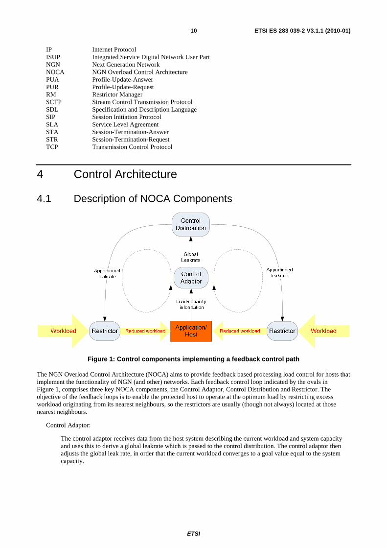
Figure 1: Control components implementing a feedback control path
The NGN Overload Control Architecture (NOCA) aims to provide feedback based processing load control for hosts that implement the functionality of NGN (and other) networks. Each feedback control loop indicated by the ovals in Figure 1, comprises three key NOCA components, the Control Adaptor, Control Distribution and Restrictor. The objective of the feedback loops is to enable the protected host to operate at the optimum load by restricting excess workload originating from its nearest neighbours, so the restrictors are usually (though not always) located at those nearest neighbours.
Control Adaptor:
The control adaptor receives data from the host system describing the current workload and system capacity and uses this to derive a global leakrate which is passed to the control distribution. The control adaptor then adjusts the global leak rate, in order that the current workload converges to a goal value equal to the system capacity.
ETSI
ETSI ES 283 039-2 V3.1.1 (2010-01)11
Control Distribution:
The control distribution component shares the global leak rate between the restrictors on the basis of simple local policies. These policies enable defined service levels or fairness requirements to be realised. The control distribution uses the Generic Overload Control Application Protocol (GOCAP) to transmit leak rate information to restrictors on remote hosts.
Restrictor:
The restrictor is a leaky bucket rate limiter that is request priority aware. It is controlled by the leak rate received from the control distribution component and restricts the workload presented to the host which the control is protecting.
The components and functions shown in Figure 1 should be thought of as being located above the top level of the protocol stacks running at the overloaded target (the GOCAP Master) and sources (GOCAP Slaves). As an example, two communications application instances running on the source and target may use ISUP to communicate with each other in establishing and clearing-down voice calls. Beneath ISUP, the protocol stack (in descending order) could be SIP-I/TCP/IP.
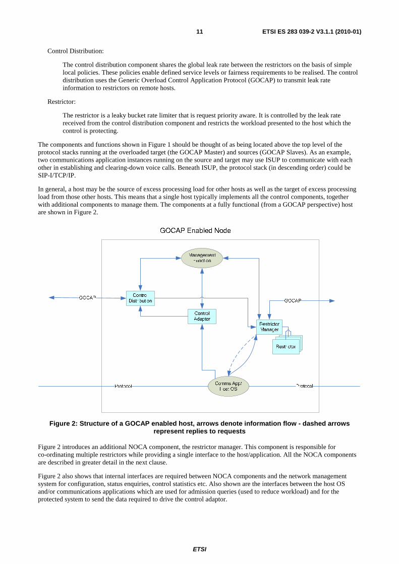
In general, a host may be the source of excess processing load for other hosts as well as the target of excess processing load from those other hosts. This means that a single host typically implements all the control components, together with additional components to manage them. The components at a fully functional (from a GOCAP perspective) host are shown in Figure 2.
Management Function
Comms App/ Host OS
GOCAP Enabled Node
Control Distribution
Control Adaptor
Restrictor Manager
LRLRRestrictor
GOCAP
ProtocolProtocol
GOCAP
Figure 2: Structure of a GOCAP enabled host, arrows denote information flow - dashed arrows represent replies to requests
Figure 2 introduces an additional NOCA component, the restrictor manager. This component is responsible for co-ordinating multiple restrictors while providing a single interface to the host/application. All the NOCA components are described in greater detail in the next clause.
Figure 2 also shows that internal interfaces are required between NOCA components and the network management system for configuration, status enquiries, control statistics etc. Also shown are the interfaces between the host OS and/or communications applications which are used for admission queries (used to reduce workload) and for the protected system to send the data required to drive the control adaptor.
ETSI
ETSI ES 283 039-2 V3.1.1 (2010-01)12
4.2 Detailed Description of NOCA Components and Behaviour
4.2.1 Overview
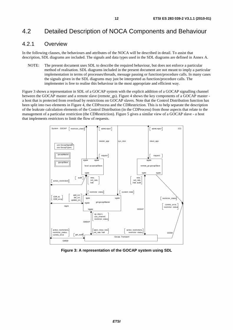
In the following clauses, the behaviours and attributes of the NOCA will be described in detail. To assist that description, SDL diagrams are included. The signals and data types used in the SDL diagrams are defined in Annex A.
NOTE: The present document uses SDL to describe the required behaviour, but does not enforce a particular method of realisation. SDL diagrams included in the present document are not meant to imply a particular implementation in terms of processes/threads, message passing or function/procedure calls. In many cases the signals given in the SDL diagrams may just be interpreted as function/procedure calls. The implementer is free to realise this behaviour in the most appropriate and efficient way.
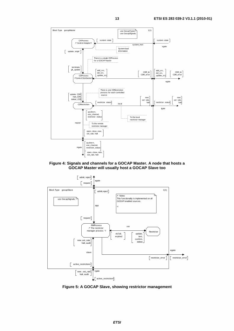
Figure 3 shows a representation in SDL of a GOCAP system with the explicit addition of a GOCAP signalling channel between the GOCAP master and a remote slave (remote_gs). Figure 4 shows the key components of a GOCAP master - a host that is protected from overload by restrictions on GOCAP slaves. Note that the Control Distribution function has been split into two elements in Figure 4, the CDProcess and the CDRestriction. This is to help separate the description of the leakrate calculation elements of the Control Distribution (in the CDProcess) from those aspects that relate to the management of a particular restriction (the CDRestriction). Figure 5 gives a similar view of a GOCAP slave - a host that implements restrictors to limit the flow of requests.
get_audit
active_restrictions,restrictor_status,comms_error
restrictor_status
audit
active_restrictions
new ,set_rate,halt, audit
active_restrictions,restrictor_status
up, dow n,use_channel,restrictor_status
open, close, new ,set_rate, halt
add_src,del_src,
update_src
CDR_Id,CDR_error
restrictor_status
new , set_rate,halt
comms_error,restrictor_status
use GocapSignals;use GocapTypes;
local_gs:gocapSlave
Gocap_Transport
remote_gs:gocapSlave
gm:gocapMaster
1(1)
gocapSlave
gocapMaster
admit,reject
master_app
agate
request
admit,reject
slave_app
agate
request
restrictor_status
egate
system_state
sys_mon
sgate
System GOCAP
GSSM
lgate
rgate
egate
mgmt
egate
GMSAP
mgate GSSAP
rgate
GMSM
Figure 3: A representation of the GOCAP system using SDL
ETSI
ETSI ES 283 039-2 V3.1.1 (2010-01)13
There is a single CDProcessfor a GOCAP master
restrictor_statusrestrictor_status
To the remoterestrictor manager
To the local restrictor manager
new ,set_rate,
halt
new ,set_rate,
halt
up,dow n,use_channel,restrictor_status
up,dow n,use_channel,restrictor_status
open, close, new ,set_rate, halt
open, close, new ,set_rate, halt
There is one CDRestrictionprocess for each controlled source
CDR_Id,CDR_error
CDR_Id,CDR_error
update_CDR,halt_CDR,
delete_CDR
CDRestriction
add_src,del_src,update_src
add_src,del_src,update_src
System loadinformationupdate_origin
terminate,glr_update
CDProcess/*Control Distribution*/
system_state
sgatesystem_mon
system_stateCAProcess/* Control Adaptor*/
1(1)use GocapTypes;use GocapSignals;
Block Type gocapMaster
egate
master
mgate
local
lgate
Figure 4: Signals and channels for a GOCAP Master. A node that hosts a GOCAP Master will usually host a GOCAP Slave too
restrictor_error
new ,set_rate,halt, audit
active_restrictions
/* NotesThis functionality is implemented on all GOCAP enabled sources.
*/
ok,fail,expired
update,test,
confirm,delete
active_restrictions
rgate
1(1)
RMProcess/* The restrictor
manager process */
new , set_rate,halt, audit
use GocapSignals;
admit,reject
app
agate
admit, reject
request
request
egate
restrictor_error
Restrictor
Block Type gocapSlave
rmr
slave
Figure 5: A GOCAP Slave, showing restrictor management

ETSI
ETSI ES 283 039-2 V3.1.1 (2010-01)14
4.2.2 Control Adaptor (CAProcess)
The purpose of the Control Adaptor is to master the adaptation of a control variable, which is translated into restriction values by the distribution function, such that the arrival rate of requests associated with that Control Adaptor converges on some goal arrival rate.
4.2.2.1 Control Adaptor Data
Each control adaptor shall be provisioned with the following parameters:
• the termination interval, terminationPending, used to identify when adaptive control should cease;
• control initiation factor, u, used to scale the initial value of the control variable;
• a minimum significant arrival rate change, d; and
• the effective origin scalar, a, used to modify the adaptation behaviour when the system capacity falls below the sum of the capacity guarantees offered to the sources.
The use of the origin scalar parameter, a, is discussed in detail in Annex F.
Each control adaptor shall maintain the following state data:
• the control variable, C (also known as the global leakrate);
• the previous value of the control variable, oldC;
• a periodically-updated estimate of the total arrival rate of service requests, Y;
• the previous estimate of the arrival rate of service requests, oldY;
• periodically updated values for total arrival rate goal, G, for service requests to that resource;
• the previous value of the total arrival rate goal, oldG;
• the current smallest si/wi ratio multiplied by W, the sum of the weights, R, as signalled from the Control
Distribution; and
• the current sum of static capacity allocations, S, as signalled from the Control Distribution.
The use of R and S is described in more detail in Annex F.

ETSI
ETSI ES 283 039-2 V3.1.1 (2010-01)15
4.2.2.2 CAProcess signals
Table 1: Signals sent or received by the Control Adaptor Process
Signal Dirn Comments system_state(Y Real, G Real)
recv Received periodically by the CA process from thesystem. It informs the CA of the current work arrival rate, Y, and the goal work arrival rate (or the system capacity), G, and effectively drives the control adaptation. For simple systems where the host is servicing only one request type, the work arrival rate may simply be the rate at which requests are arriving. For hosts which service a variety of different request types, the work arrival rate is a weighted mean arrival rate, where the weights represent the processing effort associated with servicing each request.
update_origin(S Real, R Real) recv Received from the Control Distribution and defines the origin used for the adaptation algorithm. S is the sum of the static capacity allocations for the controlled restrictors and R is the smallest s/w ratio of all the restrictions multiplied by W, the sum of the weights. The motivation for this origin correction is described in Annex F.
glr_update(C Real, f Real) send When the overload control is active (CA in state "adapting" or "terminating"), the glr_update signal shall be sent by the CA process to the Control Distribution whenever the control variable is updated. This will cause the Control Distribution to calculate updated restriction rates for all the active sources that are loading the host. C is the control variable, also known as the global leak rate, and f is the capacity modification factor.
terminate send When the CA has determined that the overload is over, it sends this signal to the Control Distribution. This halts the remote restrictions.
4.2.2.3 Control Adaptor Behaviour
The Control Adaptor shall behave as shown in Figures 6 and 7. It has five states:
• Passive: In this state the control adapter shall receive periodically updated estimates of the workload arrival rate, Y, and the goal workload arrival rate (or system capacity), G, (via the system_state signal). If the arrival rate exceeds the goal arrival rate, then the control adapter shall:
- set the control variable, C, to the value of the goal arrival rate times the control initiation factor, C = uG;
- send the Control Distribution a glr_update signal with control variable value, C, and that the capacity modification parameter value, f, where;
⎟⎠
⎞⎜⎝
⎛=S
aGf ,0.1min .
- set oldC, oldY and oldG to the values of C, Y and G respectively;
- enter the "adapting" state.
• Adapting: In the "adapting" state the Control Adapter shall monitor the arrival rate, Y, and the goal arrival rate, G, adapting its internal state whenever a system_state signal arrives as follows:
If (Y - oldY < d) and (oldY < oldG) and (Y < G) then
⎟⎠
⎞⎜⎝
⎛=
==
===
S
aGf
GoldG
YoldY
tempC
ColdC
oldCtemp
,1min:
:
:
:
:
:

ETSI
ETSI ES 283 039-2 V3.1.1 (2010-01)16
Send the Control Distribution a glr_update signal with control variable value, C, and the capacity modification parameter value, f. Arm a timer that expires after a time terminationPending. Enter the "terminating" state.
Otherwise:
( ) ⎟⎟⎠
⎞⎜⎜⎝
⎛⎟⎠
⎞⎜⎝
⎛ −−+=
⎟⎠
⎞⎜⎝
⎛=
===
Y
GRSf
Y
CGGC
S
aGf
GoldG
YoldY
ColdC
1,max:
,1min:
:
:
:
Send the Control Distribution a glr_update signal with control variable value, C, and the capacity modification parameter value, f.
• Terminating: The Control Adapter shall continue to monitor the arrival rate, Y, and the goal arrival rate, G, adapting its internal state whenever a system_state signal arrives as follows:
If (Y - oldY < d) and (oldY < oldG) and (Y < G) then:
⎟⎠
⎞⎜⎝
⎛=
==
===
S
aGf
GoldG
YoldY
tempC
ColdC
oldCtemp
,1min:
:
:
:
:
:
Send the Control Distribution a glr_update signal with control variable value, C, and the capacity modification parameter value, f.
Otherwise:
( ) ⎟⎟⎠
⎞⎜⎜⎝
⎛⎟⎠
⎞⎜⎝
⎛ −−+=
⎟⎠
⎞⎜⎝
⎛=
===
Y
GRSf
Y
CGGC
S
aGf
GoldG
YoldY
ColdC
1,max:
,1min:
:
:
:
Send the Control Distribution a glr_update signal with control variable value, C, and the capacity modification parameter value, f. Reset the termination pending timer. Enter the "adapting" state.
If the timer expires, the Control Adaptor shall enter the "wait_TP" state.

ETSI
ETSI ES 283 039-2 V3.1.1 (2010-01)17
• wait_TP: The purpose of the "wait_TP" state is to synchronise control termination with a system_state signal. When that system_state signal arrives, the current arrival rate, Y, shall be compared with the goal arrival rate, G, and if Y ≤ G, the Control adaptor shall send a terminate signal to the Control Distribution and enter the state "wait_TP2". If Y > G, then the Control Adaptor shall:
� Update the internal state as follows:
( ) ⎟⎟⎠
⎞⎜⎜⎝
⎛⎟⎠
⎞⎜⎝
⎛ −−+=
⎟⎠
⎞⎜⎝
⎛=
===
Y
GRSf
Y
CGGC
S
aGf
GoldG
YoldY
ColdC
1,max:
,1min:
:
:
:
� Send the Control Distribution a glr_update signal with control variable value, C, and the capacity modification parameter value, f.
� Enter the "adapting" state.
• wait_TP2: The purpose of the "wait_TP2" is to sample the unrestricted workload arrival rate before returning to the "passive" state. When the system_state signal arrives, the current arrival rate, Y, shall be compared with the goal arrival rate, G, and if Y ≤ G, the Control adaptor shall enter the state "passive". If Y > G, then the Control Adaptor shall send a glr_update signal with the current control variable value, C, and the capacity modification parameter value, f, (i.e. with recalculating C or f) and enter the state "adapting". This is equivalent to restarting the adaptation at the same point as when the termination pending timer expired.
In all states, the Control Adaptor shall record updates of the current adaptation origin data sent from the Control Distribution. On receipt of an update_origin signal, no action (other than updating the adaptation origin parameters, S and R) need be taken.

ETSI
ETSI ES 283 039-2 V3.1.1 (2010-01)18
system_state(Y,G)
adapting
glr_update(C,f)to CDProcess
true
temp := oldC;oldC := C;C := temp;oldY := Y;oldG := G;if (S > a*G ) then f := a*G/Selse f := 1.0f i;
falseY < (oldY + d)and oldY < oldG
and Y < G
oldC := C;oldY := Y;oldG := G;if (S > a*G ) then f := a*G/Selse f := 1.0fi;C := C*G/Y + f*(S - R)*(1.0 - G/Y);C := call maximum(C,G);
glr_update(C,f)to CDProcess
terminating
/******* Configurable Parameters ***********/DCL a, /* origin offset parameter <= 1.0 */ /* (See Annex B) */ d, /* Smallest significant arrival rate change */ u /* Initiator factor - scales the initial value of C */ Real;
/* ... and the termination pending period */DCL terminationPending Duration;
passive
system_state(Y,G)
Y > G
C := u*G;if (S > a*G ) then f := a*G/Selse f := 1.0f i;oldC := C;oldY := Y;oldG := G;
true
passive
false
glr_update(C,f)to CDProcess
adapting -
update_origin(S,R)/* From CDProcess */
*adapting
DCL C, /* Control_variable*/ oldC, /* old control variable value*/ Y, /* Current arrival rate */ oldY, /* Previous arrival rate */ G, /* Goal Arrival Rate */ oldG, /* Previous Goal Value */ R, /* Smallest s/w ratio from CD */ S, /* Sum of capacity allocations */ temp, /* To allow sw aps */ f Real; /* Capacity Modif ier */
timer TP; /* for termination Pending */...R := 0.0;S:=0.0;
set(now + terminationPending,TP)
use GocapSignals;
1(2)Process
(1,1)
CAProcess
Figure 6: The Control Adaptor states passive and adapting
NOTE: Initialisation details are omitted.

ETSI
ETSI ES 283 039-2 V3.1.1 (2010-01)19
temp := oldC;oldC := C;C := temp;oldY := Y;oldG := G;if (S > a*G ) then f := a*G/Selse f := 1.0f i;
true
We've terminated the control - now w ait w hile w e sample the arrival rate
Wait here as w e w ant tosynchronise the terminatesignal w ith a system_stateupdate
TP
adapting
reset(TP)
terminating
glr_update(C,f)to CDProcess
falseY < (oldY + d)and oldY < oldG
and Y < G
system_state(Y,G)
oldC := C;oldY := Y;oldG := G;if (S > a*G ) then f := a*G/Selse f := 1.0fi;C := C*G/Y + f*(S - R)*(1.0 - G/Y);C := call maximum(C,G);
glr_update(C,f)to CDProcess
terminating
w ait_TP
system_state(Y,G)
Y > G
passive
false
glr_update(C,f)to CDProcess
adapting
true
terminateto CDProcess
Y > G
false
true
system_state(Y,G)
w ait_TP2
The overload has comeback so start adapting w here w e left off
Just in case the overloadcomes back before w e turn off the restrictions
2(2)Process CAProcess
(1,1)
Figure 7: The Control Adaptor states terminating, wait_TP and wait_TP2 showing the terminating behaviour
4.2.2.4 Generating Control Adaptor Input
There are two key inputs for the CA, the target arrival rate and the actual arrival rate. These two parameters are delivered to the CA via the signal system_state(arrRate, goal) which is received from the environment (i.e. from outside the defined GOCAP system). While it is a normative requirement that the GOCAP CA uses this data to ensure that the adaptation of the control is rapid, the manner in which these parameters are calculated depends on the internal architecture of the protected device. Annex D contains a discussion of possible approaches to deriving these parameters.
4.2.3 Control Distribution (SDL: CDProcess)
A server protected by GOCAP shall implement a Control Distribution. It is created and configured when the GOCAP subsystem is started. It is the responsibility of the Control Distribution to take the control variable mastered by the control adapter and generate leak rates to send to restrictors. The Control Distribution process does not communicate with the restrictor manager directly; it maintains a reference to the appropriate CDRestriction process for each restriction it manages. The CDRestriction hides the channel management functionality from the CD.
4.2.3.1 Control Distribution data
The Control Distribution shall hold and maintain the following data:
W : The total of the weights allocated to all the controlled sources. S : The total of the capacity guarantees allocated to all the controlled sources. R : W multiplied by the smallest s/w ratio, used for setting the adaptation origin.

ETSI
ETSI ES 283 039-2 V3.1.1 (2010-01)20
The following additional data shall be held for each restriction managed by that Control Distribution:
SEQUENCE { restn PId, /* A reference to the CDRestriction process that handles this restriction */ serial Integer /* A serial number used to refer to this restriction. */ w Real, /* The restriction weight used to calc leakrates */ s Real, /* The capacity guarantee */ static Boolean /* A flag which when "true" means that the leakrate is set "manually" and */ /* when "false" means the leakrate is updated in alignment to the GLR. */ }
4.2.3.2 Control Distribution Signals
The Control Distribution process sends or receives the signals described in Table 2.
Table 2: Signals sent or received by the Control Distribution
Signal Dirn Comments add_src(src src_data) recv Received from the environment, this signal describes a new controlled source
which may consist of a number of identifiable request flows. In a statically configured GOCAP, all these signals would come during start-up. In dynamically configured GOCAP, these signals may appear at any time, driven by request flows recognised by the application.
del_src(i Integer) recv Received from the environment, this signal describes a controlled source that is no longer required. This is used for dynamic source removal when operating in an environment where sources come and go, or to remove a static restriction.
update_src(i Integer, new_s Real, new_w Real)
recv Received from the environment, this signal changes the weight and capacity guarantee for a controlled source that already exists. This enables an application to implement more flexible resource allocation policies.
CDR_Id(I Integer) send Is returned to the sender of the add_src signal with the serial number of the created restriction.
CDR_error send Is returned to sender of an add_src, del_src or update_src signal if there was an error processing the signal.
update_origin(S Real, R Real)
send Sent to the Control Adaptor (CAProcess) and defines the origin used for the adaptation algorithm. S is the sum of the individual capacity allocations, si,
and R is W multiplied by the smallest si/wi ratio of all the dynamic sources.
This data is used by the CA to modify the origin used for the adaptation and to calculate the capacity modification factor,f. The motivation for this origin correction is described in Annex F.
glr_update(C Real, f Real) recv Received from the Control Adaptor whenever the control variable is updated. The C is the new control variable and f is the capacity modification parameter.
terminate recv When the CA has determined that the overload is over, it sends this signal to the Control Distribution. This halts the remote restrictions.
update_CDR(r Real) send After the CD has created a restrictor on the slave, the leak rate can be amended using the restrictor_update signal, where the parameter "r" is the new rate.
halt_CDR send This is sent to the CDRestriction process to turn the restriction off. delete_CDR send Sent to the CDRestriction when the restriction is no longer required.
4.2.3.3 Control Distribution Behaviour
The behaviour of the control Distribution shall be as described in Figures 8 and 9. The Control distribution has a single state, "idle". The behaviour resulting from each of the input signals is as follows:
glr_update: When a glr_update signal is received from the Control Adaptor which contains a new value of the control variable, C, and the capacity modification parameter f, then the Control_Distribution shall, for each controlled restriction;

ETSI
ETSI ES 283 039-2 V3.1.1 (2010-01)21
calculate new leakrate, ri, using the expression:
( )fSCW
wfsr i
ii −+= ,
where W is the sum of all the weights, wi, and S is the sum of all the capacity guarantees, si.
� send an update_CDR signal with the new leakrate to the CDRestriction specified for that source.
terminate: If the Control_Distribution receives a "terminate" signal from the control adaptor, the Control distribution shall, for each controlled restriction, send a halt_CDR signal to the relevant CDRestrictor.
If an add_src, update_src or del_src signal arrives, it shall be handled as specified in "any" below.
add_src: If an add_src signal arrives the Control Distribution shall:
- create a unique serial number that can be used to refer to this restriction;
- create a new CDResriction to handle this source. (The CDRestriction provides the interface between the Distribution Function and the whatever transport logic is used to control the restrictions.);
- create an entry in the local database for this restriction using the data in the signal;
- send a CDR_Id signal to the sending process with the serial number of the new restriction;
- if the restriction is static, send an update_CDR(s) signal to the newly created CDRestriction in order to start restricting at the rate specified by the s parameter in the src data from the add_src signal;
- otherwise, update local values of normalisation constant, W, the total guarantees, S, and the W*min(s/w) ratio, R, and send an update_origin(S, R) signal to the Control Adaptor.
update_src: If an update_src signal arrives then the Control Distribution shall:
- find the matching record in the local database;
- update the s and w with the new values specified in the signal;
- if the restriction is static, send an update_CDR(s) signal to the specified CDRestriction in order to set the restriction leakrate to that specified by the s parameter;
- otherwise:
� update the values of the normalisation constant, W, the total guarantees, S, and W*min(s/w) ratio, R, as described in Figure 9;
� send an update_origin(S, R) signal with the S and R values to the Control Adaptor.
del_src: If a del_src signal arrives then the Control Distribution shall:
- find the matching restriction in the local database;
- if the restriction is not static:
� update the values of the normalisation constant, W, the total guarantees, S, and W*min(s/w) ratio, R, as described in Figure 9;
� send an update_origin(S,R) signal with the new S and R values to the Control Adaptor;
- send a delete_CDR signal to the CDRestriction for that src; and
- delete the restriction information from the local database.

ETSI
ETSI ES 283 039-2 V3.1.1 (2010-01)22
NOTE: A "controlled source" is treated as a single source by the Control Distribution. The data that describes a source may refer to multiple data flows (multiple signatures each associated with a restrictor splash). A real source, i.e. a different host, may be represented as a single "controlled source" or as several, depending on how the applications want to control load from that source. For example, SIP REGISTER messages and SIP INVITE messages from a particular host may be treated as:
� (a) separate flows from the same controlled source, in which case the total aggregate flow is controlled; or
� (b) separate controlled sources, in which case each message type is controlled separately.
Additional transitions for state "idle" are described on the next page
Empty = rSetEmpty = rSet
true
i:=take(q);q:=del(i,q);
true
i:=take(q);q:=del(i,q);
idle
W:=0.0;S:=0.0;R:=0;N:=0;rSet := Empty;
1(2)
use GocapSignals;
/* A database of the restrictions that w e distribute leakrates to */CDDatabase ::= SEQUENCE OF SEQUENCE { restn PId, /* The CDRestriction process w e use to communicate */ serial Integer, /* The serial numner of this restriction */ w Real, /* The restriction w eight used to calc leakrates */ s Real, /* The capacity gaurantee */ static Boolean /* If true, Restriction is controlled manually */ };IntegerSet ::= SET OF Integer;
dcl cddb CDDatabase; /* The restriction database */
dcl rSet IntegerSet; /* A set holding valid local restriction IDs */
glr_update(C,f)
idle
q:=rSet;
Empty = q
true
/* Calculate new leak rate */rate := f * cddb(i).s + cddb(i).w * (C - f*S)/W;
update_CDR(rate)to cddb(i).restn
terminate
idle
cddb(i).static
false
false
false
cddb(i).static
halt_CDRto cddb(i).restn
true
Empty = q
q:=rSet;
idle
false
/* Local variables */dcl W Real; /* the sum of all the w eights */dcl S Real; /* the sum of all the capacity guarantees */dcl R Real; /* the smallest s/w ration of all the sources */dcl N Integer; /* The number of restrictions w e are managing */dcl C Real; /* The global leakrate */dcl f Real; /* capacity factor */dcl src SourceData; /* Information about a new source */dcl rate Leakrate; /* A calculated leak rate - temp variable */ dcl i Integer; /* a loop variable */dcl q IntegerSet; /* A set used to iterate over all the valid IDs */
Process
(1,1)
CDProcess
false
true
false
true
Figure 8: The behaviour of the Control Distribution when handling signals from the CAProcess

ETSI
ETSI ES 283 039-2 V3.1.1 (2010-01)23
restnID.master := myGocapID;restnID.num := i
/* Provisioned Data */dcl myGocapID GOCAPID;
rSet := del(i, rSet);
false
cddb(i).static
idle
true
update_CDR(src.s)to cddb(i).restn
W := W + src.w ; S := S + src.s;
falsesrc.static
true
i:=0;
idle
del_src(i)
i in rSet
W := W - cddb(i).w ;S := S - cddb(i).s;
delete_CDRto cddb(i).restn
update_origin(S,R)
idle
update_origin(S,R)
CDR_Id(cddb(i).serial)to sender
CDRestriction(restnID,src)
false
cddb(i).restn := offspring;cddb(i).static:= src.static;cddb(i).w := src.w ;cddb(i).s := src.s;cddb(i).serial := i;
i in rSet
i := i+1;
add_src(src)
idle
/********************************** We use the local restrictor serial number to track each restriction. We use rSet to hold the set of IDs in use to simplify iteration etc.**********************************/dcl restnPId PId;dcl new _s Real; /* A temp variable for capacity allocation */dcl new _w Real; /* A temp variable for w eight allocation */dcl restnID RestrictionID; /* A temp variable to hold the restrictionID */
update_src(i,new _s,new _w )
2(2)
/* Update the restn data */cddb(i).w := new _w ;cddb(i).s := new _s;
idle
update_origin(S,R)
W := W + cddb(i).w ;S := S + cddb(i).s;
i in rSet
true
CDR_error(i,invalidID)to sender
idle
false
cddb(i).static
false
update_R
/*******************************We have a procedure torecalculate R, the smallests/w ratio, w hen required.*******************************/
update_CDR(new _s)to cddb(i).restn
idle
true
update_R
update_R update_R
Process CDProcess
(1,1)
true
true
false
Figure 9: Adding, updating and removing controlled sources from the Control Distribution
4.2.4 CDRestriction
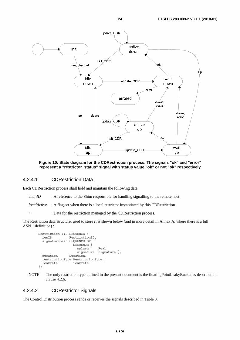
The CDRestriction represents the restrictor for the CDProcess and handles the instantiation of restrictions on local or remote GOCAP slaves. It is a requirement that GOCAP be able to interoperate with systems that do not support GOCAP, or in situations where the GOCAP signalling stream becomes unusable, without unfairly acting against those system that do support GOCAP. To this end, if a host does not support GOCAP, or if two way communication between the GOCAP master and a GOCAP slave cannot be established, the CDRestriction will automatically instantiate the restriction on the local host (as an ingress restriction) so that non conforming sources do not gain unfair advantage. The separation of this behaviour into the CDRestriction means that Control Distribution does not need to maintain per restriction state regarding the behaviour of the GOCAP protocol. The CDRestriction tracks the availability of the signalling path to the remote GOCAP slave (states *_up and *_down) and whether a restriction has actually been instantiated or not (states active_* and idle_*). A state diagram for the CDRestriction is shown in Figure 10.
ETSI
ETSI ES 283 039-2 V3.1.1 (2010-01)24
Figure 10: State diagram for the CDRestriction process. The signals "ok" and "error" represent a "restrictor_status" signal with status value "ok" or not "ok" respectively
4.2.4.1 CDRestriction Data
Each CDRestriction process shall hold and maintain the following data:
chanID : A reference to the Shim responsible for handling signalling to the remote host.
localActive : A flag set when there is a local restrictor instantiated by this CDRestriction.
r : Data for the restriction managed by the CDRestriction process.
The Restriction data structure, used to store r, is shown below (and in more detail in Annex A, where there is a full ASN.1 definition) :
Restriction ::= SEQUENCE { resID RestrictionID, signatureList SEQUENCE OF SEQUENCE { splash Real, signature Signature }, duration Duration, restrictionType RestrictionType , leakrate Leakrate };
NOTE: The only restriction type defined in the present document is the floatingPointLeakyBucket as described in clause 4.2.6.
4.2.4.2 CDRestrictor Signals
The Control Distribution process sends or receives the signals described in Table 3.

ETSI
ETSI ES 283 039-2 V3.1.1 (2010-01)25
Table 3: Signals sent or received by the CDRestrictor
Signal Dirn Comments update_CDR(r Leakrate) recv Indicates that the leak rate for the restrictor has changed to the new value r. halt_CDR() recv Indicates that the restriction should be deleted. delete_CDR() recv Indicates that the restriction should be deleted and the CDRestriction
processes terminated (i.e. control of that source is not required in the future).
open(a AddressList, b ShimType)
send Request a reference to a GOCAP shim to handle signalling to the remote host. This will, if necessary, initiate a new signalling channel between the GOCAP master and the remote slave. The parameters a & b are derived from the source definition data provided to the CDRestriction on instantiation.
Close() send Inform the shim that the signalling channel to the remote slave is no longer required.
new(r Restriction) send Request for the instantiation (creation) of a restriction (i.e. rate limiter) by a GOCAP slave. The parameter r contains all the information required to create a restriction.
set_rate(i restrictionID, r leakrate)
send Request an update to the leak rate of an existing restriction. Parameter i is the unique restriction ID (GOCAPID and local serial number) and r is the new leakrate.
halt(i restrictionID) send Request the deletion of an existing restriction. Up recv Indicates that the signalling channel to the remote GOCAP slave is
available. Down recv Indicates that the signalling channel to the remote GOCAP slave is
unavailable. use_channel(c PId) recv Received in response to an "open" signal, the parameter c is a reference to
the GOCAP shim that will handle signalling to the remote slave. restrictor_status( i restrictionID, s RestrictionStatus)
recv Received in response to a "new", "set_rate" or "delete" request and indicates if the requested change was successful. Parameter i is the restriction ID and s is the restriction status, one of ok, invalidGOCAPID, scopeViolation, invalidAddressType, invalidType,
internalError, invalidID or unknownID.
4.2.4.3 CDRestrictor Behaviour
The behaviour of the CDRestrictor (CDR) shall be as described in Figures 11, 12 and 13.
On instantiation, the CDR shall use the provided source data to generate the data needed to describe the restriction that it manages. It shall also send an open signal to the GOCAP Channel Manager in order to obtain a reference, chanID, to the shim that handles communication between the CDR and the remote restrictor manager. The CDR shall then go to state "idle_down" The behaviour in each of the states is as follows:
"idle_down" & "idle_up":
• In these states the restriction is not active.
• If an up signal arrives the CDR shall move to state "idle_up".
• If a down signal arrives the CDR shall move to state "idle_down".
• If an update_CDR is received the CDR shall:
- update its definition of the restrictor with the new leakrate;
- set the timer T1 to half the restrictor duration;
- send a new signal with the restrictor definition to the local restrictor manager (if is state "idle_down") or the remote restrictor manager via the shim (if in state "idle_up");
- if in state "idle_down", set the localActive flag to true; and
- then enter state "wait_down" from "idle_down" or "wait_up" from "idle_up".

ETSI
ETSI ES 283 039-2 V3.1.1 (2010-01)26
If a delete_CDR signal arrives, the CDR shall, if its chanID is not null, send a close signal to the shim. In any case, the CDR shall then terminate.
w ait_dow n
set(now +r.duration/2,T1)set(now +r.duration/2,T1)
/* local data */dcl r Restriction; /* Data relating to this restriction */dcl chanID PId; /* The process ID ofthe channel w e use to talk to the slave */timer T1; /*Used to refresh the restriction after duration/2 has elapsed. */dcl localActive Boolean; /* Used to indicate w hether a local restriction is active. */
/* temp variables */dcl rate Leakrate; dcl stat RestrictionStatus; dcl rid RestrictionID;
use GocapSignals;use GocapTypes;
1(3)
open(src.addrs,src.shim)
init
use_channel(chanID)
idle_dow n
r.flow s := src.flow s;r.resID := myID;r.duration := src.duration;r.restrictionType := src.rType;localActive := false;
idle_dow n
up
idle_up
update_CDR(rate)
r.leakrate := rate;localActive := true
new (r)via local
w ait_up
new (r)via master
r.leakrate := rate
update_CDR(rate)
idle_dow n
dow n
idle_up
close
delete_CDR
idle_dow n,idle_up, errored
/*-------------------------------------- Note: If this restriction is a local restriction w e get null as the chanID and w ill never receive the "up" signal. This means that w e need to check that the chanID is valid before w e try to close the channel w hen w e are in a dow n state.---------------------------------------*/
null =chanID
false
true
*
Process
(0,); fpar myID RestrictionID, src SourceData;
CDRestriction
Figure 11: The CDRestriction process behaviour with no active restriction
"wait_down":
In state "wait_down" the CDR is waiting for a reply from the local restrictor manager to the new signal. If a restrictor_status signal arrives, the CDR shall inspect the restriction status and if it has value ok move to state "active_down". Any other value of the restriction status shall cause the CDR to enter state "errored". No other signals are processed in state "wait_down", but signals are preserved for processing in the next state.
"errored":
If a delete_CDR signal arrives, the CDR shall, if its chanID is not null, send a close signal to the shim. In any case, the CDR shall then terminate.

ETSI
ETSI ES 283 039-2 V3.1.1 (2010-01)27
localActive := false
true
false
localActive
true
halt(r.resID)via local
falselocalActive
elsestat
else
errored
stat
From the local slaveShould not block!
*
w ait_dow n
restrictor_status(rid,stat)
2(3)
active_dow n
*
active_up
dow n
w ait_up
restrictor_status(rid,stat)
w ait_dow n
new (r)via local
set(now + r.duration/2,T1);
ok
localActive := true
Process CDRestriction
(0,); fpar myID RestrictionID, src SourceData;
ok
Figure 12: Checking the creation of new restrictions
"wait_up":
• in state "wait_up" the CDR is waiting for a reply from the remote restrictor manager to a new signal. If a restrictor_status signal arrives, the CDR shall inspect the restriction status and, if it has value ok, move to state "active_up", destroying any local restriction. Any other value of the restriction status, or the arrival of a down signal, shall cause the CDR to:
• create a local restrictor, if none exists; and
• enter the state "wait_down".
No other signals are processed in state "wait_up", but signals are preserved for processing in the next state.
"active_up":
• In state "active_up" the CDR is controlling an active restriction on a remote host.
• When an update_CDR signal arrives, or timer T1 expires, the CDR shall set timer T1 to half the restriction duration and sends a set_rate signal to the shim for forwarding to the remote GOCAP slave, finally returning to state "active_up".
• When a halt_CDR signal arrives, the CDR shall cancel (reset) timer T1, send a halt signal to the shim to forward to the remote slave, and move to state idle_up.
• When a delete_CDR signal arrives, the CDR shall send a halt signal to the shim to forward to the remote slave, send a close signal to the shim and then terminate.
• When a restrictor_status signal arrives, the CDR shall inspect the restriction status and if it has value ok , stay in state "active_up". If the status is unknownID, then the CDR shall send a new signal with the restrictor definition to the remote restrictor manager (via the shim), set the timer T1 to half the restrictor duration and shall then enter state "wait_up". Any other value of the restriction status, or a down signal, shall cause the CDR to send a new signal with the restrictor definition to the local restrictor manager, set the localActive flag to true, set the timer T1 to half the restrictor duration and enter state "wait_down".

ETSI
ETSI ES 283 039-2 V3.1.1 (2010-01)28
"active_down":
• In state "active_down" the CDR is controlling an active restriction on a local host.
• When an update_CDR signal arrives, or timer T1 expires, the CDR shall set timer T1 to half the restriction duration and sends a set_rate signal to the local GOCAP slave, finally returning to state "active_down".
• When a halt_CDR signal arrives, the CDR shall cancel (reset) timer T1, send a halt signal to the local slave, send a close signal to the shim if defined (if chanID is not null), and move to state idle_down.
• When a delete_CDR signal arrives, the CDR shall send a halt signal to the shim to forward to the remote slave, and then terminate.
• When an up signal arrives, the CDR shall send a new signal with the restrictor definition to the remote restrictor manager (via the shim), set the timer T1 to half the restrictor duration, send a halt signal to the local slave and shall then enter state "wait_up".
• A restrictor_status signal is ignored in state "active_down".
localActive := false
localActive := true
restrictor_status signalsare ignored in this state
close
halt(r.resID)to chanID
delete_CDR
idle_up
halt(r.resID)to chanID
active_up
set_rate(r.resID,r.leakrate)to chanID
set(now +r.duration/2,T1)
T1,update_CDR(r.leakrate)
active_up
halt_CDR
reset(T1)
restrictor_status(rid,stat)
unknow nID stat
active_upw ait_up
new (r)to chanID
set(now + r.duration/2,T1);
ok
dow n
w ait_dow n
new (r)via local
set(now + r.duration/2,T1);
else
set(now + r.duration/2,T1);
reset(T1)
true
false
null =chanID
close
halt(r.resID)via local
delete_CDR
idle_dow n
halt(r.resID)via local
active_dow n
set_rate(r.resID,r.leakrate)via local
set(now + r.duration/2,T1)
T1, update_CDR(r.leakrate)
w ait_up
up
active_dow n
new (r)to chanID
halt_CDR
Need to account forloopback restrictions
3(3)Process CDRestriction
(0,); fpar myID RestrictionID, src SourceData;
Figure 13: CDRestriction behaviour when the restriction it represents is active
4.2.5 Restrictor Manager (RMProcess)
The Restrictor Manager is responsible for storing the currently active restrictions and enabling applications to query those restrictions.

ETSI
ETSI ES 283 039-2 V3.1.1 (2010-01)29
4.2.5.1 Restrictor Manager Data
The RMProcess shall be provisioned with three data items that provide default parameters for new restrictors. These are:
priorities : a Real array of 0..15 priority thresholds.
initialFill : A real parameter that sets the initial value of the bucket fill for new restrictors. The parameter may be zero, but more usually will be similar to the threshold in the priorities array that corresponds to normal priority requests.
maxFill : A real parameter that sets the maximum allowed value of the bucket fill in restrictors. The parameter maxFill shall always be greater than the highest threshold in the priorities array, and it is recommended that it be set to twice the highest priority.
The RM shall also maintain a database of restrictions. The implementation of that database is implementation dependent, but the interface to the database is defined in terms of six primitive actions. Each record in the database associates a Restriction data structure (see the ASN.1 data definitions in Annex A) with the ID of the leaky bucket restrictor. The Restriction data structure, expanded out to atomic types, is shown below:
Restriction ::= SEQUENCE { resID SEQUENCE { -- a RestrictionID type master GOCAPID,- Unique Master identification string. num Integer - The serial number of the CDRestriction process }, -- End of RestrictionID flows SEQUENCE OF -- Flows type SEQUENCE { splash Real, -- The amount the restrictor fill is incremented -- when a request from this flow is accepted. signature SEQUENCE { -- a Signature type appSrcs SEQUENCE OF Address, -- The IP addresses of source(slave) as -- understood by the applications on the -- host on which the restrictor is being -- created. appDests SEQUENCE OF Address, -- The IP addresses of destination(master) as -- understood by the applications on the host -- on which the restrictor is being created. appLabel ApplicationLabel, -- e.g. "SIP" or "SIP.REGISTER" etc appAddrs SEQUENCE OF ApplicationAddress, -- A list of application layer addresses, e.g. -- SIP URIs, phone numbers. Some addresses may -- wildcarded e.g. "*.bt.com" addrType ApplicationAddressType -- Type of application address - needed for -- address handing and for wildcard rules that -- apply to that address type. }, -- End of Signature Type }, -- End of Flows type duration Duration, -- How long the restriction is valid for. restrictionType RestrictionType, leakrate Leakrate -- The rate at which work may be forwarded
};
NOTE: The only restriction type defined in the present document is the floatingPointLeakyBucket as described in clause 4.2.6.
The database shall be implemented so that efficient retreival of information is possible on the basis of resID and of matches between the signatureList and application request signatures.

ETSI
ETSI ES 283 039-2 V3.1.1 (2010-01)30
4.2.5.2 Restrictor Manager Signals
The signals received and sent by the Restrictor Manager are described in Table 4.
Table 4: Restrictor Manager Signals and Events
Signal Dirn Comments new(r Restriction) recv On receipt, the RMProcess shall create the appropriate restrictor and add the
restriction data, associated with the restrictor ID into its database of restrictions. This signal will usually come from the GSlave SessionHandler (having received the request from a GOCAP Master), but may also be invoked by an application or by management action.
set_rate( id RestrictionID, r Leakrate)
recv A request to change the leak rate of a particular restriction. The RestrictionID is used to locate the data relating to that restriction in the database, so that the restrictor process ID can be retrieved. The new leak rate is then passed to the restrictor via a update(Leakrate) signal.
halt(rid RestrictionID) recv This signal is used to delete a particular restrictor. The RestrictionID, rid, is used to locate the information relating to that restriction in the database, so that the restrictor process ID can be retrieved. The database entry is then deleted and the restrictor process ID is used to terminate the restrictor process.
audit(c CCID) recv Retrieve a list of restrictions that have been instantiated on behalf of the specified GOCAP master. On receiving this signal, the RM process will search its database of restrictions and return a list of restrictions via the active_restrictions signal.
restrictor_status( rid RestrictionID, stat RestrictionStatus)
send After a new, set_rate or halt signal, the Restrictor Manager shall return the result of the request via a restrictor_status signal. The value of rid is as specified in the original request (even if the restrictor does not exist) and status is one of ok, invalidID or deleted.
active_restrictions( auditList RestrictionList)
send In response to an audit request (audit signal) the restrictor Manager shall return a list of all the active restrictions for the specified GOCAP master.
request( sig Signature, p Priority)
recv Received from any application that wants check to see if it safe to forward a request. The Signature is used by the RM to establish with restrictions apply and the priority reflects the request priority and affects the chances of rejection as described in clause 4.2.6.3.
admit send Sent to the application if the service request should be admitted. reject send Sent to the application is the service request may be rejected. test(splash Real, p Priority)
send This signal is sent to a particular restrictor to check if the restrictor will admit the request.
update(r Leakrate) send Sent to a particular restrictor in order to update its leakrate. confirm(splash Real) send Sent to each restrictor that was involved in a particular request analysis to
update its state appropriately given the overall result. The single parameter is the splash - the amount to increase the bucket fill.
delete send Sent to a restrictor process to kill it. ok recv Received from the restrictor as a response to a test signal. It signals that the
application request may be admitted. fail recv Received from the restrictor as a response to a test signal. It signals that the
application request may not be admitted. expired recv Received from the restrictor when its lifetime timer expires.
4.2.5.3 Restrictor Manager Behaviour
The restrictor manager shall be created and configured when the overload control is armed. It manages 0 or more active restrictors. The dynamic behaviour of the Restrictor Manager shall be as described in the SDL diagram of the RM process, shown in Figure 14 and an admission request from an application shall be handled as described in Figure 15.
The restrictor manager shall instantiate and delete restrictors as requested by control distribution components (either local or remote), by the management system or by a local application.

ETSI
ETSI ES 283 039-2 V3.1.1 (2010-01)31
A restriction request, new(Restriction), contains a Restriction data structure that gives the restrictor_ID and one or more specific restriction "signatures" (source node, target node, application_label, application_address list), each with a request splash. Some fields may be wild carded - e.g. for node load control, the application_label and application_address fields are likely to contain wildcards. When the Restrictor Manager is requested to start a Restrictor, it shall do the following:
1) delete any existing restrictor with the same restrictionID;
2) instantiate and initialise the Restrictor; and
3) add the Restriction data to its database of restrictions, associated with the restrictor process ID.
When the restrictor manager is requested to stop a restrictor, via a halt(RestrictionID), the restrictor manager shall remove the restrictor from its database of restrictions and delete the corresponding restrictor.
The restrictor manager shall receive restrictor updates via an set_rate(RestrictionID,Leakrate) signal. The restrictor manager shall use the restrictorID to retrieve the restrictor process ID from its restriction database, and then send a update(Leakrate) message to the restrictor.
The Restrictor Manager shall send a restrictorStatus signal to indicate the outcome of a new, set_rate or halt request as shown in Figure 14.
The applications on the host will query the restrictor manager to establish if a request may be forwarded to another host, or if an incoming request should be rejected by sending a request(Signature, Priority) signal to the Restrictor Manager. The signal from the application supplies a restrictor signature (source node, target node, application_label) and a request priority. The restrictor manager shall look for restrictions in its restriction database that match that request signature. (Multiple matches are possible because restrictor signature fields may be wildcarded.) For each matching restriction it shall retrieve the restrictor process ID and the splash appropriate to the request and then interrogate each of the restrictors in turn, as shown in Figure 15, sending an "admit" signal to the application if all the restrictors admit the request or "reject" signal if one or more restrictors rejected the request. If there is no match, then the query is granted, and the restrictor manager shall send the "admit" signal to the application.
The management function or local applications may also request the creation and destruction of local restrictors by the restrictor manager, allowing the network operator to use the NOCA infrastructure for statically defined (i.e. not driven by a NOCA control adaptor) restrictions as required.

ETSI
ETSI ES 283 039-2 V3.1.1 (2010-01)32
deleteRestriction(rid)
deleteto rpid
f indRestrictor(r.resID,rpid,err)
/*Get the Restrictor processID from the
RestrictionID */
err
restrictor_status(rid,deleted) to sender
restrictor_status(rid,ok) to sender
restrictor_status(rid,ok) to sender
Note: An additional transition is def ined on Page 2.
active_restrictions(auditList) to sender
getChannelRestrictions(connexID,auditList)
getChannelRestrictions/* Take a GOCAP ID and f ind all the restrictions that originate from that
connection*/
audit(connexID)
/* Note These 5 procedures have defined interfaces, but detailed behaviour is lef t to the implementor */
f indRestrictor/* Take a RestrictionID and return the restrictor PId */
findMatchingRestrictors/* Take an application request signature, and return a list of matchingrestrictor PIds - each
associated w ith a request splash*/
use GocapTypes;
/* These quantities are initialised and maintained by the RMProcess logic */ dcl rList ApplicableRestrictors;dcl auditList RestrictionList;dcl result, allow , err Boolean;dcl sig Signature;dcl p RequestPriority;dcl r Restriction;dcl rid RestrictionID;dcl rpid , app PId;dcl rate Leakrate;dcl connexID GOCAPID;
ready
ready
new (r)/* From SMHandler */
set_rate(rid,rate)/* From SMHandler */
halt(rid)/* From SMHandler */
Restrictor(r.leakrate, priorities, initialFill,
maxFill, r.duration, r.resID)
/* Create the restrictor process*/
1(2)
findRestrictor(rid,rpid,err)
/*Get the Restrictor processID from the
RestrictionID */
saveRestriction/* Take restrictor data and
restrictor PId and save them*/
saveRestriction(r,of fspring)
update(rate)to rpid
deleteRestriction/* Take a RestrictionID and
remove the restriction from the database*/
findRestrictor(rid,rpid,err)
/*Get the Restrictor processID from the
RestrictionID */
deleteto rpid
expired(rpid,rid)/*It's time expired!*/
/* Notes:This describes the restrictor manager behaviour. The initilisation behaviour is ommitted for clarity.*/
/* These quantities shall be provisioned */
dcl priorities PriorityList; dcl initialFill Real; /* The initial bucket fill */dcl maxFill Real; /* The max allow ed bucket fill */
/* N.B Bucket thresholds in the priorities array shall all be less than maxFill. */
deleteRestriction(rid)
err false
restrictor_status(rid,invalidID) to sender
trueerrfalse true
Process
(1,1)
RMProcess
true
false
Figure 14: Restrictor management behaviour for the Restrictor Manager
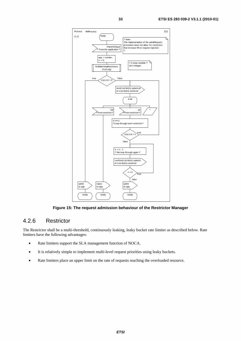
ETSI
ETSI ES 283 039-2 V3.1.1 (2010-01)33
/* A loop variable */dcl n Integer;
ready
admitto app
ready
2(2)
f indMatchingRestrictors(rList,sig)
ready
request(sig,p)/* From the application */
admitto app
rejectto app
app := sender;n := 0;
ready
true
n := n - 1/* We loop through again */
confirm(rList.list(n).splash)to rList.list(n).restrictor
n > 0
truerList.cnt > n
n:=n+1/*Loop through each restrictor*/
fail/*from restrictor*/
*ok/*From restrictor*/
w ait
test(rList.list(n).splash,p)to rList.list(n).restrictor
rList.cnt = 0
/* Note:This implementation of the admitRequest procedure does not allow for restrictors that increase fill on request rejection.*/
Process RMProcess
(1,1)
false
true
false
false
Figure 15: The request admission behaviour of the Restrictor Manager
4.2.6 Restrictor
The Restrictor shall be a multi-threshold, continuously leaking, leaky bucket rate limiter as described below. Rate limiters have the following advantages:
• Rate limiters support the SLA management function of NOCA.
• It is relatively simple to implement multi-level request priorities using leaky buckets.
• Rate limiters place an upper limit on the rate of requests reaching the overloaded resource.

ETSI
ETSI ES 283 039-2 V3.1.1 (2010-01)34
4.2.6.1 Restrictor data
Restrictors are created and destroyed by the Restrictor Manager as required. Each instance of a restrictor shall maintain the information described in Table 5.
Table 5: Restrictor Data
SDL Name Type Initial value Notes fill Real > 0.0 Specified by the
RestrictorManager This is the bucket fill.
maxFill Real > 0.0 Specified by the RestrictorManager
It is recommended that this be set to be twice the largest threshold.
lastUpdate Time current time A record of when the fill parameter was last updated. pList Real[] >0.0 Specified by the
RestrictorManager A vector of floating point fill thresholds, pList(i) is the threshold for the ith priority.
r Real ≥0.0 specified by requestor
The leak rate in s-1.
lifetime Duration specified by requestor
The restriction is expired if not refreshed in an interval of length Duration.
4.2.6.2 Restrictor signals
Table 6: Restrictor Signals and Events
Signal Dirn Comments test(splash Real, p Priority) recv From the Restrictor Manager to check if the restrictor will admit a request.
update(r Leakrate) recv Update the leak rate of the leaky bucket.
confirm(splash Real) recv Confirms the application level success of a service request. The parameter is used to increase the fill of the leaky bucket.
delete recv Sent to a restrictor process to kill it. ok send A request has been accepted by the restrictor. fail send A request has been rejected by the restrictor. expired send The restrictor lifetime timer has expired.
4.2.6.3 Restrictor behaviour
There are a number of ways of implementing leaky buckets, and it is up to the implementer to select a suitable technique. All implementations shall be functionally identical to the implementation described in Figure 16 and in the SDL files supplied with the present document.
The restrictor shall admit a request of priority i and weight splash if the current fill+ splash is less than or equal to the ith threshold, pList[i]. After a request has been accepted, the fill of the leaky bucket shall be increased by the amount splash.
The fill of the bucket is continuously reduced at a rate of leakrate. In real implementations, of course, the fill does not change continuously; rather the fill is updated whenever the state of the bucket is sampled.
When the Restrictor is created, and whenever the leak rate of the restrictor is updated, the timer T1 shall be set to expire after a time lifetime. If the timer expires, the Restrictor shall inform the Restrictor Manager via an "expired" signal. The Restrictor Manager will then delete the restriction data associated with this restrictor and then terminate the restrictor. This prevents the restrictor from persisting if, due to some error, a message to delete the restrictor does not arrive.
A key point to note is that the restrictors used for GOCAP shall have a two step request acceptance, an initial test, and a confirmation step only taken after the restrictor manager has established whether the request has been admitted. This is because when the application makes an admission request to the restrictor manager, there may be multiple restrictors that apply to that request, all of which must admit the request in order for the request to be successful.

ETSI
ETSI ES 283 039-2 V3.1.1 (2010-01)35
else
fill > maxFill
f ill := maxFillf ill := 0.0
/* Notes This describes the implementation of a leakey bucket rate limiter that does not require th explicit use of timers.It is described here in terms of one process for each restriction. Other implemenation are possible and w ould be acceptable.N.B it is assumed that the granularity of the time based function and operators is appropriate. Time values must be in seconds, and include fractional seconds.*/
1(1)
use GocapSignals;use GocapTypes;
idle
update(new _r)
test(splash,p) conf irm
(splash)delete
dcl new _r Leakrate;dcl last_time Time;dcl f ill, splash Real;dcl p RequestPriority;dcl t Duration;timer T1;
set(now +lifetime,T1);
f ill := fill - r*(now - last_time);last_time := now ;r := new _r;
f ill := fill +(CALL Uniform(-0.5,0.5));/* Uniform(-0.5,0.5) is a function that returns a random number in the range -0.5 <= x <= 0.5 */
set(now + lifetime, T1);f ill := initialFill;last_time := now ;
'f ill'
idle
f ill := f ill - r*(now - last_time);last_time := now
fill < 0.0
idle
true
f ill := 0.0
f ill < 0.0
f ill + splash > pList(p)
false
fail to parent
ok to parent
true false
f ill := f ill + splash
false
idle
true
fill := maxFill
f ill > maxFill
T1
expired(self,resID)to parent
idle
Process
(0,); fpar r Leakrate, pList PriorityList, initialFill Real, maxFill Real, lifetime Duration, resID RestrictionID;
Restrictor
Figure 16: Leaky bucket implementation
4.2.7 GOCAP Transport
4.2.7.1 The structure of the GOCAP transport layer.
Figure 3 shows that the remote GOCAP slave and the local GOCAP master communicate via a GOCAP_transport. This transport represents the GOCAP signalling path and Figure 17 shows the key components for of the GOCAP-transport module. It defines two blocks, the GMaster and the GSlave together with a third that represents the actual transport functions (e.g. Diameter transport functions as defined in RFC 3588 [2] or SIP transport functions as defined in RFC 3265 [6]). The function of the GMaster is to encode the commands new, set_rate and halt from the CDRestriction and audit requests from the management in messages of the relevant transport protocol. The GSlave decodes the transport protocol messages to generate the equivalent new, set_rate, halt and audit requests to the remote Restriction Manager.

ETSI
ETSI ES 283 039-2 V3.1.1 (2010-01)36
Signals on this channel depend on the transportmechanism used
Signals on this channel depend on the transport
mechanism used
GSSM
restrictor_status,comms_error
GMaster GSlave
transport/* Different mechanisms are possible, e.g. Diameter, SIP Subscribe/Notify */
... ....
... ...
up, dow n,use_channel,restrictor_status
GMSAP
open, close, new ,set_rate, halt
new ,set_rate,audit, halt
GSSAP
active_restrictions,restrictor_status
active_restrictions,restrictor_status,comms_error
GMSM
get_audit
1(1)Block Type gocapTransport
Figure 17: GOCAP transport between CDRestriction on Master (GMSAP) and Restrictor Manager on Slave (GSSAP)
There is a singlechannel manager
There is one GocapShim for each controlled GOCAP Slave
GMSM
comms_error,restrictor_status,active_restrictions
...
mxxx
xxx
...
open
use_channel
new , set_rate,halt, close
use GocapSignals;
close_channel
new _ref,get_audit,
GMSAP
up,dow n,restrictor_status
xxxShim
ChannelManager
comms_error
get_audit
/* Local signals */SIGNAL close_channel(PId), new _ref(PId);
1(1)Block GMaster
Figure 18: The relationship between ChannelManager and GocapShim in GMaster
Figure 18 shows how the GMaster entity behaviour may be described in terms of two different processes. There is a single instance of the channel manager, which is responsible for the creation and management of the GocapShims and there are zero or more shims, of which there is one shim for each GOCAP slave that this master communicates with. Figure 19 shows how the GSlave entity behaviour may be described in terms of two different processes. There is a single instance of a GocapListener and a SessionHandler instance for each GOCAP master that communicates with this slave. The GocapListener is responsible for the creation and management of SessionHandlers and the adjudication of restrictor scope claims.

ETSI
ETSI ES 283 039-2 V3.1.1 (2010-01)37
comms_error
restrictor_status
active_restrictions,restrictor_status
new , set_rate,halt, audit
...
...
...
...
SessionHandler/* One process perGOPCAP Master */
GocapListener/* Listens for GOCAP messages
and manages creation and deletionof individual sessions */
1(1)Block xxxGSlave
xxx
sxxx
GSSAP
GSSM
Figure 19: The GocapListener and SessionHander elements of the GSlave
4.2.7.2 Channel Manager
The role of the Channel Manager is to manage the protocol shims that implement the transport of the GOCAP signalling flow between the CDRestriction process and the remote restrictor. It also provides a redirection facility so that requests can be directed at the correct shim instance.
4.2.7.2.1 Channel Manager Data
The channel manager shall be provisioned with the following data:
• myID The unique GOCAP ID of the host;
• siglist A list of restrictor scopes for which this GOCAP Master can create restrictions.
The Channel Manager shall also maintain a database of created shim instances linked to the transport address each shim is associated with.
4.2.7.2.2 Channel Manager Signals
The Channel Manager process sends or receives the signals described in Table 7.
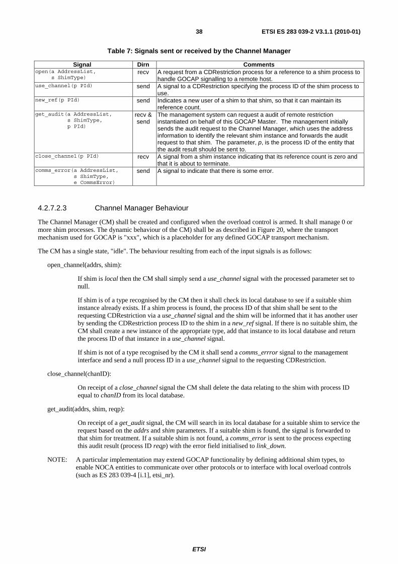
ETSI
ETSI ES 283 039-2 V3.1.1 (2010-01)38
Table 7: Signals sent or received by the Channel Manager
Signal Dirn Comments open(a AddressList, s ShimType)
recv A request from a CDRestriction process for a reference to a shim process to handle GOCAP signalling to a remote host.
use_channel(p PId) send A signal to a CDRestriction specifying the process ID of the shim process to use.
new_ref(p PId) send Indicates a new user of a shim to that shim, so that it can maintain its reference count.
get_audit(a AddressList, s ShimType, p PId)
recv & send
The management system can request a audit of remote restriction instantiated on behalf of this GOCAP Master. The management initially sends the audit request to the Channel Manager, which uses the address information to identify the relevant shim instance and forwards the audit request to that shim. The parameter, p, is the process ID of the entity that the audit result should be sent to.
close_channel(p PId) recv A signal from a shim instance indicating that its reference count is zero and that it is about to terminate.
comms_error(a AddressList, s ShimType, e CommsError)
send A signal to indicate that there is some error.
4.2.7.2.3 Channel Manager Behaviour
The Channel Manager (CM) shall be created and configured when the overload control is armed. It shall manage 0 or more shim processes. The dynamic behaviour of the CM) shall be as described in Figure 20, where the transport mechanism used for GOCAP is "xxx", which is a placeholder for any defined GOCAP transport mechanism.
The CM has a single state, "idle". The behaviour resulting from each of the input signals is as follows:
open_channel(addrs, shim):
If shim is local then the CM shall simply send a use_channel signal with the processed parameter set to null.
If shim is of a type recognised by the CM then it shall check its local database to see if a suitable shim instance already exists. If a shim process is found, the process ID of that shim shall be sent to the requesting CDRestriction via a use_channel signal and the shim will be informed that it has another user by sending the CDRestriction process ID to the shim in a new_ref signal. If there is no suitable shim, the CM shall create a new instance of the appropriate type, add that instance to its local database and return the process ID of that instance in a use_channel signal.
If shim is not of a type recognised by the CM it shall send a comms_errror signal to the management interface and send a null process ID in a use_channel signal to the requesting CDRestriction.
close_channel(chanID):
On receipt of a close_channel signal the CM shall delete the data relating to the shim with process ID equal to chanID from its local database.
get_audit(addrs, shim, reqp):
On receipt of a get_audit signal, the CM will search in its local database for a suitable shim to service the request based on the addrs and shim parameters. If a suitable shim is found, the signal is forwarded to that shim for treatment. If a suitable shim is not found, a comms_error is sent to the process expecting this audit result (process ID reqp) with the error field initialised to link_down.
NOTE: A particular implementation may extend GOCAP functionality by defining additional shim types, to enable NOCA entities to communicate over other protocols or to interface with local overload controls (such as ES 283 039-4 [i.1], etsi_nr).

ETSI
ETSI ES 283 039-2 V3.1.1 (2010-01)39
/* Channel manager for GOCAP shim type xxx.xxx may be "diameter", "sip_sub_not" or any otherprotocol that has been defined in a shim spec.
comms_error(null,null, linkDow n) to reqp
true
false
chanID = null
use GocapTypes;
new _ref(sender)to chanID
xxx
idle
getChannel(addrs, shim, chanID)
chanID = null
chanID := offspring
xxxShim(myID, sender, siglist)
saveChannel(addrs,shim,chanID)
use_channel(chanID)to sender
false
/* w e have three procedures for maintaining a local database that links the transport addresses of the slave message handler to the process ID of the coressponding message handling shim */
Received from the environment(i.e. the management system)
idle idle
deleteChannel(chanID)
close_channel(chanID)
get_audit(addrs,shim,reqp) to chanID
getChannel(addrs,shim,chanID)
idle
/* Provisioned data */dcl myID GOCAPID;dcl siglist AuthScopeList;
use_channel(null)
shim
/* local temp variables */dcl addrs AddressList;dcl shim ShimType; /* Local, native etc*/dcl chanID, reqp PId;
get_audit(addrs,shim,reqp)
open(addrs,shim)
idle getChannel saveChannel deleteChannel
comms_error(addrs, shim, unknow nTransport)
elselocal
idle
use_channel(null)
1(1)Process
(1,1)
ChannelManager
true
Figure 20: The GOCAP channel manager behaviour
4.2.7.3 Shim Process
Figure 18 shows how the GMaster is implemented with a single Channel Manager and a number of Shim processes to implement the communication between Master and Slave. This Clause describes the requirements that have to be met by all shim types.
4.2.7.3.1 Shim Process Signals
Any shim process shall be capable of receiving the following signals: new, set_rate, halt, close, new_ref, get_audit. It shall also be capable of generating, comms_error, up and restrictor_status. A shim process may optionally generate close_channel, down and active_restrictions signals if appropriate.
4.2.7.3.2 Shim Process Behaviour
The detailed behaviour of any particular shim process depends on its purpose, but all shim processes shall meet the behavioural requirements described in this clause.
If a shim receives new signal from a CDRestriction with process ID p, it shall send either a restrictor_status signal or a down signal to p. A restrictor_status signal shall contain information regarding the success or failure of the request in the status field. The down signal is sent if communication with the remote GOCAP slave is not established, or has failed. The delay between receiving the new signal and sending a response shall not exceed some system defined time limit (this is because the CDRestriction process blocks in the "wait_up" state after sending a new signal).
If a shim receives a set_rate or halt signal it may respond with a restrictor_status message.

ETSI
ETSI ES 283 039-2 V3.1.1 (2010-01)40
If a shim receives a new_ref signal, it shall increment an internal reference count and add the included process ID to the list of CDRestriction processes it is permitted to communicate with.
If a shim receives a close signal, it shall delete the sender from its list of CDRestriction processes it is permitted to communicate with.
If a shim receives a get_audit signal it should attempt to obtain from the GOCAP slave a list of all the current restictions associated with the Gocap Master. It shall then generate towards the process indicated in the get_audit signal either an active_restrictions signal, containing the list obtained from the slave, or if it is unable to obtain such a list, a comms_error signal.
A shim process may send an up or a down signal at any time to any process in its list of CDRestriction processes it is permitted to communicate with. The down signal should be sent if the shim looses communication with the GOCAP slave; the up signal should be sent when communication is re-established.
4.2.7.4 GocapListener
The detailed behaviour of the GocapListener is tightly bound to the protocol being used to transport the GOCAP primitives. Its role may be summarised as:
• It listens for GOCAP messages from the transport layer and directs the messages to the appropriate session handlers.
• It polices the scope claimed by Gocap Masters. A scope clause in a new session request that overlaps with an existing scope clause from a different GOCAP master will result in the new session request being rejected.
• It handles GOCAP transport session sessions, particularly it maintains a view of the health of the connection between the Master and the Slave.
4.2.7.5 SessionHandler
The detailed behaviour of the SessionHandler is tightly bound to the protocol being used to transport the GOCAP primitives. Its role may be summarised as:
• It translates the transport dependent signalling into new, set_rate, halt and audit signals that it forwards to the Restrictor Manager.
• It encodes resulting restrictor_status and active_restrictions into messages in the supported protocol so that the GOCAP Master can track the outcome of or each request.
• It ensures that new restriction requests conform to the agreed scope between the Master and the Slave (i.e. it is the SessionHandler that should reject rejections from a GOCAP Master that exceed the agreed scope of the session).
5 GOCAP over Diameter
5.1 Introduction Clause 4 describes the components and behaviour of a GOCAP system. It also describes the information flows needed to support the control. This clause describes how the required information is sent across the network between the GOCAP Master and Slave using Diameter. A similar mechanism is described in clause 6 which uses a SIP Subscribe-Notify mechanism. Other mechanisms may be defined separately. The choice of a particular mechanism for a particular application depends on the nature of the hosts and the protocols that they already support. Of course, whichever mechanism is chosen, the behaviours of the hosts and therefore of the overload control will be the same.

ETSI
ETSI ES 283 039-2 V3.1.1 (2010-01)41
5.2 Use of the Diameter base protocol The Diameter Base Protocol as specified in RFC 3588 [2] shall apply except as modified by the defined GOCAP application specific procedures, commands and AVPs. Unless otherwise specified, the procedures specified in RFC 3588 [2] (including error handling and unrecognized information handling) are unmodified.
In addition to the AVPs defined within clause 5.2.5, the Diameter AVPs from the Diameter base application (RFC 3588 [2]) are reused within the Diameter messages of the GOCAP application. Accounting functionality (Accounting Session State Machine, related command codes and AVPs) is not used in the GOCAP interface.
The GOCAP application is defined as an IETF vendor specific Diameter application with application ID 16777254, where the vendor is ETSI. The vendor identifier assigned by IANA to ETSI (http://www.iana.org/assignments/enterprise-numbers) is 13019.
With regard to the GOCAP protocol, the GOCAP Slave acts as a Diameter server, in the sense that it is the element that handles restriction requests for a particular realm. The GOCAP Master acts as the Diameter Client, in the sense that is the element requesting restrictions to be instantiated. A Master (Diameter client) can only send requests to manipulate restrictions on the GOCAP slave (Diameter server) if the Master has already initiated a Diameter session with the Slave using the AGR command.
NOTE: Diameter routing (proxying) for GOCAP sessions is only allowed if the proxies themselves are engineered such that processing overload of the proxies is impossible.
5.2.1 Advertising GOCAP support
The GOCAP Master and Slave shall advertise the support of GOCAP specific Application by including the value of the application identifier (16777254) in the Auth-Application-Id AVP and the value of 13019 (ETSI) in the Vendor-Id AVP of the Capabilities-Exchange-Request and Capabilities-Exchange-Answer commands as specified in RFC 3588 [2], i.e. as part of the Vendor-Specific-Application-Id AVP. The Capabilities-Exchange-Request and Capabilities-Exchange-Answer commands are specified in the Diameter Base Protocol.
5.2.2 Securing Diameter messages
For secure transport of Diameter messages, see TS 133 210 [4].
5.2.3 Accounting functionality
Accounting functionality (accounting state machine, related command codes and AVPs) are not used in the present document.
5.2.4 GOCAP commands
Existing Diameter command codes from the Diameter base protocol RFC 3588 [2] and the NASREQ Diameter application (RFC 4005 [3]) are used with the GOCAP specific AVPs. A GOCAP specific Auth-Application id is used together with the command code to identify the GOCAP messages.
NOTE 1: The notion of NAS (Network Access Server) is not used here, NASREQ is just used for protocol purposes, not for its functional meaning.
NOTE 2: Diameter routing (proxying) for GOCAP sessions is only allowed if the proxies themselves are engineered such that processing overload of the proxies is impossible.
5.2.4.1 AA-Request (AAR) command
The AAR command, indicated by the Command-Code field set to 265 and the 'R' bit set in the Command Flags field, is sent by a GOCAP master (Diameter client) to a GOCAP slave (Diameter server) in order to obtain authorisation to request restrictions within the scope(s) specified.

ETSI
ETSI ES 283 039-2 V3.1.1 (2010-01)42
Message Format:
<AA-Request> ::= <Diameter Header: 265, REQ, PXY > <Session-Id> {Auth-Application-Id} {Origin-Host} {Origin-Realm} {Destination-Host} {Destination-Realm} {Auth-Request-Type} {Auth-Session-State} {Auth-Scope} *[Proxy-Info] *[Route-Record]
5.2.4.2 AA-Answer (AAA) Command
The AAA command, indicated by the Command-Code field set to 265 and the 'R' bit cleared in the Command Flags field, is sent by the Slave to the Master in response to the AAR command. Each scope which has been authorised is described in the Auth-Scope AVP. If no scope AVPs are included in the reply, then the original request has failed.
Message Format:
<AA-Answer> ::= <Diameter Header: 265, PXY > <Session-Id> {Auth-Application-Id} {Origin-Host} {Origin-Realm} {Auth-Request-Type} {Auth-Session-State} {Result-Code} [Auth-Scope] [Error-Message] [Error-Reporting-Host]
5.2.4.3 Profile-Update-Request (PUR) command
This PUR command, indicated by the Command-Code field set to 307 and the 'R' bit set in the Command Flags field, is sent by a GOCAP master to a GOCAP slave in order to create, update, delete or audit one or more GOCAP restrictors on the Slave. This command is defined in TS 129 329 [5] and used with additional AVPs defined in the present document.
Message Format:
<PU-Request> ::= <Diameter Header: 307, REQ, PXY > <Session-Id> {Auth-Application-Id} {Origin-Host} {Origin-Realm} {Destination-Host} {Destination-Realm} {GOCAP-Body} *[Proxy-Info] *[Route-Record]
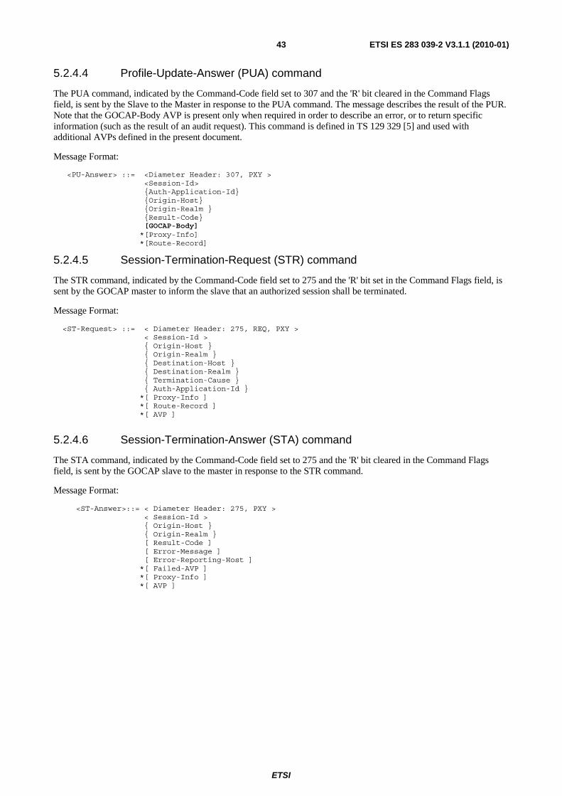
ETSI
ETSI ES 283 039-2 V3.1.1 (2010-01)43
5.2.4.4 Profile-Update-Answer (PUA) command
The PUA command, indicated by the Command-Code field set to 307 and the 'R' bit cleared in the Command Flags field, is sent by the Slave to the Master in response to the PUA command. The message describes the result of the PUR. Note that the GOCAP-Body AVP is present only when required in order to describe an error, or to return specific information (such as the result of an audit request). This command is defined in TS 129 329 [5] and used with additional AVPs defined in the present document.
Message Format:
<PU-Answer> ::= <Diameter Header: 307, PXY > <Session-Id> {Auth-Application-Id} {Origin-Host} {Origin-Realm } {Result-Code} [GOCAP-Body] *[Proxy-Info] *[Route-Record]
5.2.4.5 Session-Termination-Request (STR) command
The STR command, indicated by the Command-Code field set to 275 and the 'R' bit set in the Command Flags field, is sent by the GOCAP master to inform the slave that an authorized session shall be terminated.
Message Format:
<ST-Request> ::= < Diameter Header: 275, REQ, PXY > < Session-Id > { Origin-Host } { Origin-Realm } { Destination-Host } { Destination-Realm } { Termination-Cause } { Auth-Application-Id } *[ Proxy-Info ] *[ Route-Record ] *[ AVP ]
5.2.4.6 Session-Termination-Answer (STA) command
The STA command, indicated by the Command-Code field set to 275 and the 'R' bit cleared in the Command Flags field, is sent by the GOCAP slave to the master in response to the STR command.
Message Format:
<ST-Answer>::= < Diameter Header: 275, PXY > < Session-Id > { Origin-Host } { Origin-Realm } [ Result-Code ] [ Error-Message ] [ Error-Reporting-Host ] *[ Failed-AVP ] *[ Proxy-Info ] *[ AVP ]

ETSI
ETSI ES 283 039-2 V3.1.1 (2010-01)44
5.2.4.7 Abort-Session-Request (ASR) command
The ASR command, indicated by the Command-Code field set to 274 and the 'R' bit set in the Command Flags field, is sent by the GOCAP slave to inform the master that all restrictor resources for the authorized session have become unavailable.
Message Format:
<AS-Request> ::= < Diameter Header: 274, REQ, PXY > < Session-Id > { Origin-Host } { Origin-Realm } { Destination-Realm } { Destination-Host } { Auth-Application-Id } { Abort-Cause } *[ Proxy-Info ] *[ Route-Record ] *[ AVP ]
5.2.4.8 Abort-Session-Answer (ASA) command
The ASA command, indicated by the Command-Code field set to 274 and the 'R' bit cleared in the Command Flags field, is sent by the GOCAP master to the slave in response to the ASR command.
Message Format:
<AS-Answer> ::= < Diameter Header: 274, PXY > < Session-Id > { Origin-Host } { Origin-Realm } [ Result-Code ] [ Error-Message ] [ Error-Reporting-Host ] *[ Failed-AVP ] *[ Redirected-Host ] [ Redirected-Host-Usage ] [ Redirected-Max-Cache-Time ] *[ Proxy-Info ] *[ AVP ]
5.2.5 AVP definitions
The following tables summarize the AVPs used in the present document, beyond those defined in the Diameter Base Protocol RFC 3588 [2].
Table 8 describes the Diameter AVPs mandated in the present document, their AVP Code values, types, possible flag values and whether the AVP may or not be encrypted. The Vendor-Id header of these AVPs shall be set to ETSI (13019).
Table 8: Diameter AVPs Defined in the present document
AVP Flag rules (note 1) Attribute Name AVP
Code Defined Value Type (note 2) Must May Should
not Must not
May Encr.
Auth-Scope 620 5.2.6.1 UTF8String MV P Yes GOCAP-Body 621 5.2.6.2 UTF8String MV P Yes NOTE 1: The AVP header bit denoted as "M" indicates whether support of the AVP is required. The AVP header bit
denoted as "V" indicates whether the optional Vendor-ID field is present in the AVP header. For further details, see RFC 3588 [2].
NOTE 2: The value types are defined in RFC 3588 [2].

ETSI
ETSI ES 283 039-2 V3.1.1 (2010-01)45
5.2.5.1 Auth_Scope
This AVP is used by the GOCAP for two purposes.
1) For the master to claim a restrictor address space, using command AAR, for which it will request restrictions.
2) For the Slave to return those signatures for which authorisation is granted via an AAA.
NOTE: If no Auth_Scope AVPs are present in an AAA this indicates that no scope has been authorised.
The Auth_Scope AVP (AVP code 620) is of type UTF8String and contains the XML element <authScopeList> as defined in Annex C.
5.2.5.2 AVP GOCAP-Body
This AVP is used by the GOCAP master or slave to exchange GOCAP information relating to restrictors on the GOCAP slave.
The GOCAP-Body AVP (AVP code 621) is of type UTF8String and contains XML <requestList> for PUR messages and an XML <responseList> for PUA messages. These XML elements are as defined in Annex C.
5.2.6 Restrictions on AVP values
5.2.6.1 Auth-Request-Type
This AVP shall only take the value AUTHORIZE_ONLY for this application.
5.2.6.2 Auth-Session-State AVP
This AVP shall only take the value STATE_MAINTAINED for this application.
5.3 Procedures to be used with Diameter messages
5.3.1 Introduction
Clause 4.2.7 describes the generic behaviour of a Gocap transport. This clause describes how that behaviour is enhanced to support Gocap signalling over a Diameter connection. Diameter distinguishes between transport connections, which enable peers to exchange Diameter messages, and sessions, which are logical associations at the application layer, in this case between Gocap masters and slaves, identified by the Session-Id AVP. For the purposes of the present document, it is assumed that the Diameter transport connections are already established over a reliable transport and with appropriate security.

ETSI
ETSI ES 283 039-2 V3.1.1 (2010-01)46
NormativeNormative
restrictor_status,comms_error
get_audit
active_restrictions,restrictor_status,comms_error
active_restrictions,restrictor_status
new ,set_rate,audit, halt
open, close, new ,set_rate, halt
up, dow n,use_channel,restrictor_status
AAR,PNR,STR,ASAAAA,PNA,STA,ASR
AAA,PNA,STA,ASRAAR,PNR,STR,ASA
Diameter
GSlave/*Diameter*/GMaster
/*Diameter*/
1(2)Block GocapTransport
mdiamsdiam
GMSAP GSSAP
GMSM GSSM
Figure 21: GocapTransport modified to support Diameter
5.3.2 Diameter ChannelManager
The channel manager for Diameter is the same as that specified in Clause 4.2.7.2, except that it creates a DiameterShim, if one does not already exist, in response to a open( ,"diameter") signal, see Figure 22.
There is a singlechannel manager
There is one DiameterShim foreach controlled GOCAP Slave
GMSM
comms_error,restrictor_status,active_restrictions
AAA,PNA,STA,ASRerr,RAR
mdiam
diameter
AAR,PNR,STR,ASA
open
use_channel
new , set_rate,halt, close
use GocapSignals;
close_channel
new _ref,get_audit,
GMSAP
up,dow n,restrictor_status
diameterShim
ChannelManager/* for diameter */
comms_error
get_audit
/* Local signals */SIGNAL close_channel(PId), new _ref(PId);
1(1)Block GMaster
Figure 22:Transport block of a Gocap master using Diameter
5.3.3 Diameter Shim
The Diameter Shim is responsible for maintaining the application session between the GOCAP Master and the GOCAP Slave. This session may be a concatenation of a number of Diameter application sessions.

ETSI
ETSI ES 283 039-2 V3.1.1 (2010-01)47
5.3.3.1 Diameter Shim data
The Diameter Shim shall maintain the following data:
• myID : The GOCAP ID of the master, passed to the Diameter Shim on instantiation.
• sigList : A list of one or more restriction signatures that make up the scope of the session, passed to the DiameterShim on instantiation. A slave will refuse to create restrictions that are incompatible with the restriction scope agreed at session initiation.
• clientList : a database of references to CDRestriction entities that are using this shim. The first CDRestriction entry is passed to the Diameter Shim on instantiation. This list includes all the entities that need to be notified of changes in the session state.
• sessionID : This is created by the Diameter Shim on instantiation and is updated whenever a new Diameter session is created. The sessionID shall be globally and eternally unique and shall be used to form the Session-ID AVP.
5.3.3.2 Diameter shim behaviour
The Diameter Shim is responsible for a GOCAP application session, which may extend over multiple concatenated Diameter sessions. The GOCAP application session has two main states, "up" and "down" which reflect the state of communication between the GOCAP Master and the GOCAP Slave. There are three other transient states, "opening_down", and "wait_close", which may be thought of as sub states of "down", and "opening_up", which may be thought of as a sub state of "up".
On instantiation, the Diameter Shim shall create an AAR message, using its sigList to generate the Auth-Scope AVP, and send it to the GOCAP Slave. It shall then start timer T10 and enter the state "opening_down".
The behaviour of the Diameter Shim in each state shall be as follows:
In state "opening_down":
• It shall send a down signal in response to any new, set_rate or halt signals received from a CDRestriction.
• When a PUA message arrives, if the PUA Session-ID does not match the current local sessionID, discard the message otherwise, if the PUA Result-Code is set to DIAMETER_SUCCESS then change to state up.
• It shall add the details of any new CDRestriction it receives via a new_ref signal to its clientList.
• If T10 expires, the Diameter Shim shall set timer T12, send a comms_error(DiameterTimeout10) signal to the management and enter the state "down".
• If an AAA message is received, the Diameter shim shall reset timer T10 and inspect the value of the Result-Code AVP. If the Result-Code has value:
DIAMETER_SUCCESS: The Diameter Shim shall set timer T13, send an up signal to each of the CDRestrictions in the clientList and enter state "up".
DIAMETER_PARTIAL_SUCCESS: The Diameter Shim shall set timer T13, send an up signal to each of the CDRestrictions in the clientList, send a comms_error(PartialScopeDeclined) signal to the management system and enter state "up".
else: The Diameter Shim shall set timer T12, send a comms_error(DiamSessionRejected) signal to the management and enter the state "down".
• If an ASR message is received the Diameter Shim shall send a down signal to each of the CDRestrictions in its clientList, send an ASA message to the slave, increment the sessionID in accordance with [2], set timer T12 and enter state "down".
• If a close signal is received, remove the sender from the clientList and, if the client list is now empty, the Diameter shim shall set timer T14, send an STR message to the slave and enter state "wait_close".
ETSI
ETSI ES 283 039-2 V3.1.1 (2010-01)48
In state "down":
• It shall send a down signal in response to any new, set_rate or halt signals received from a CDRestriction.
• When a PUA message arrives, if the PUA Session-ID does not match the current local sessionID, discard the message otherwise, if the PUA Result-Code is set to DIAMETER_SUCCESS then change to state up.
• It shall add the details of any new CDRestriction it receives via a new_ref signal to its clientList.
• If T12 or T13 expires, the Diameter Shim shall set timer T10, send an AAR signal to the slave and enter the state "opening_down".
• If an AAA message is received, the Diameter shim shall inspect the value of the Result-Code AVP. If the Result-Code has value:
DIAMETER_SUCCESS: The Diameter Shim shall set timer T13, send an up signal to each of the CDRestrictions in the clientList and enter state "up".
DIAMETER_PARTIAL_SUCCESS: The Diameter Shim shall set timer T13, reset timer T, send an up signal to each of the CDRestrictions in the clientList, send a comms_error(PartialScopeDeclined) signal to the management system and enter state "up".
else: The Diameter Shim shall send a comms_error(DiamSessionRejected) signal to the management
• If an ASR message is received the Diameter Shim shall send a down signal to each of the CDRestrictions in its clientList, send an ASA message to the slave, increment the sessionID in accordance with [2], set timer T12 and enter state "down".
• If a close signal is received, remove the sender from the clientList and, if the client list is now empty, the Diameter shim shall set timer T14, send an STR message to the slave and enter state "wait_close".
In state "up":
• Handle new, set_rate, halt and audit signals as described in clause 5.3.3.3.
• When a PUA message arrives, if the PUA Session-ID does not match the current local sessionID, the Diameter Shim shall discard the message, otherwise, if the PUA Result-Code is set to DIAMETER_SUCCESS then the Gocap Shim shall extract the GOCAP-Body AVP and, for each of the entries in the responseList element, send a restrictor_status(rid, status) signal to the relevant CDRestrictor.
• It shall add the details of any new CDRestriction it receives via a new_ref signal to its clientList and send an up signal to that CDRestriction.
• If T11 expires, the Diameter Shim shall set timer T12, send a down signal to each of the CDRestrictions in its clientList and enter the state "down".
• If an ASR message is received the Diameter Shim shall send a down signal to each of the CDRestrictions in its clientList, send an ASA message to the slave, increment the sessionID in accordance with [2], set timer T12 and enter state "down".
• If a close signal is received, remove the sender from the clientList and, if the client list is now empty, the Diameter shim shall set timer T14, send an STR message to the slave and enter state "wait_close".
• If T13 expires, the Diameter Shim shall set timer T10, send an AAR signal to the slave and enter the state "opening_up".

ETSI
ETSI ES 283 039-2 V3.1.1 (2010-01)49
In state "opening_up":
• Handle new, set_rate, halt and audit signals as described in clause 5.3.3.3.
• When a PUA message arrives, if the PUA Session-ID does not match the current local sessionID, the Diameter Shim shall discard the message, otherwise, if the PUA Result-Code is set to DIAMETER_SUCCESS then the Gocap Shim shall extract the GOCAP-Body AVP and, for each of the entries in the responseList element, send a restrictor_status(rid, status) signal to the relevant CDRestrictor.
• It shall add the details of any new CDRestriction it receives via a new_ref signal to its clientList and send an up signal.
• If T10 expires, the Diameter Shim shall set timer T12, send a down signal to each of the CDRestrictions in its clientList and enter the state "down".
• If an AAA message is received, the Diameter shim shall reset timer T10 and inspect the value of the Result-Code AVP. If the Result-Code has value:
DIAMETER_SUCCESS: The Diameter Shim shall set timer T13 and enter state "up".
DIAMETER_PARTIAL_SUCCESS: The Diameter Shim shall set timer T13, send a comms_error(PartialScopeDeclined) signal to the management system and enter state "up".
else: The Diameter Shim shall send a comms_error(DiamSessionRejected) signal to the management , set timer T12 and enter state "down"
• If an ASR message is received, the Diameter Shim shall send a down signal to each of the CDRestrictions in its clientList, send an ASA message to the slave, increment the sessionID in accordance with [2], set timer T12 and enter state "down".
• If a close signal is received, remove the sender from the clientList and, if the client list is now empty, the Diameter shim shall set timer T14, send an STR message to the slave and enter state "wait_close".
In state "wait_close":
• If T14 expires, the Diameter Shim shall terminate.
• If an ASA message is received, the Diameter Shim shall terminate.
5.3.3.3 Generating PUR messages
PUR messages carry GOCAP commands (new, set_rate, halt and audit) between Master and Slave. A PUR message may contain more than one command and so there are two possibilities open to an implementation; send one PUR message for each individual new, set_rate, halt or audit request it receives or send one PUR message containing data for multiple Gocap requests. The first option is simplest but, because a Gocap Master may have multiple restrictions on the same slave, generating one diameter message per restriction every time the Control Distribution updates may be an unacceptable waste of resources. The solution is to define a flag, building, which is false unless the Diameter shim is currently assembling data for a PUR message. When the flag is true, gocap requests will be cached until a timer expires, at which point to PUR message containing one or more gocap commands is sent and the building flag is set to false.
There is no problem with sending multiple commands in the same PUR message if the commands are for different restrictions. If there are multiple commands for a single restriction however, there may be an issue as there is no explicit ordering of individual commands within a single PUR message. This is solved by using the actions described in Table 9 (those marked "N/A" are message combinations that cannot occur).
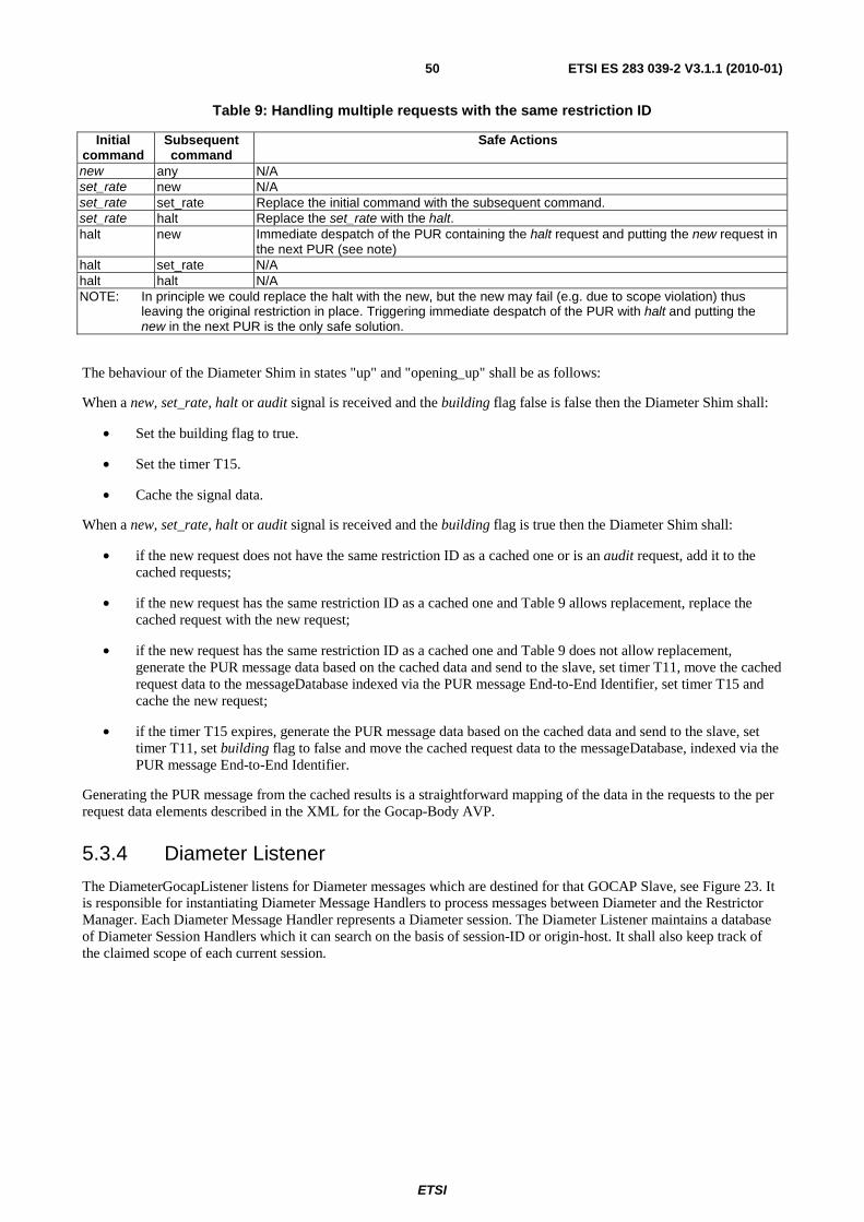
ETSI
ETSI ES 283 039-2 V3.1.1 (2010-01)50
Table 9: Handling multiple requests with the same restriction ID
Initial command
Subsequent command
Safe Actions
new any N/A set_rate new N/A set_rate set_rate Replace the initial command with the subsequent command. set_rate halt Replace the set_rate with the halt. halt new Immediate despatch of the PUR containing the halt request and putting the new request in
the next PUR (see note) halt set_rate N/A halt halt N/A NOTE: In principle we could replace the halt with the new, but the new may fail (e.g. due to scope violation) thus
leaving the original restriction in place. Triggering immediate despatch of the PUR with halt and putting the new in the next PUR is the only safe solution.
The behaviour of the Diameter Shim in states "up" and "opening_up" shall be as follows:
When a new, set_rate, halt or audit signal is received and the building flag false is false then the Diameter Shim shall:
• Set the building flag to true.
• Set the timer T15.
• Cache the signal data.
When a new, set_rate, halt or audit signal is received and the building flag is true then the Diameter Shim shall:
• if the new request does not have the same restriction ID as a cached one or is an audit request, add it to the cached requests;
• if the new request has the same restriction ID as a cached one and Table 9 allows replacement, replace the cached request with the new request;
• if the new request has the same restriction ID as a cached one and Table 9 does not allow replacement, generate the PUR message data based on the cached data and send to the slave, set timer T11, move the cached request data to the messageDatabase indexed via the PUR message End-to-End Identifier, set timer T15 and cache the new request;
• if the timer T15 expires, generate the PUR message data based on the cached data and send to the slave, set timer T11, set building flag to false and move the cached request data to the messageDatabase, indexed via the PUR message End-to-End Identifier.
Generating the PUR message from the cached results is a straightforward mapping of the data in the requests to the per request data elements described in the XML for the Gocap-Body AVP.
5.3.4 Diameter Listener
The DiameterGocapListener listens for Diameter messages which are destined for that GOCAP Slave, see Figure 23. It is responsible for instantiating Diameter Message Handlers to process messages between Diameter and the Restrictor Manager. Each Diameter Message Handler represents a Diameter session. The Diameter Listener maintains a database of Diameter Session Handlers which it can search on the basis of session-ID or origin-host. It shall also keep track of the claimed scope of each current session.

ETSI
ETSI ES 283 039-2 V3.1.1 (2010-01)51
SigList ::= SEQUENCE OF Signature;SIGNAL new _sigs(SigList);
comms_error
restrictor_status
active_restrictions,restrictor_status
new , set_rate,halt, audit
PNA
PNR,close,
new _sigs
AAR,PNR,STR,ASA
AAA,PNA,STA,ASR
DiamSessHandler/* One process perGOCAP Master */
DiameterListener/* Listens for Diameter
messages. */
1(1)Block GSlave
diameter
sdiam
GSSAP
GSSM
Figure 23: Transport block of a Gocap slave using Diameter
5.3.4.1 Diameter session initiation
When the Diameter Listener receives an AAR message, it shall examine the Origin-Host AVP, Session-ID AVP and the Auth-Scope AVP(s). If the Session-ID does not correspond to a known session, it is a new session request, otherwise it is a session renewal.
In the case of a new session, the Diameter Listener shall examine its Diameter Session database to see if a session already exists for that origin-host. If one is found then that session shall be terminated by sending an ASR (with the appropriate Session-ID AVP) to the origin-host, the restrictions associated with that session shall be deleted by sending a close signal to the corresponding Diameter Session Handler and the data associated with that session shall be removed from the Diameter Session database including the associated scope granted to that session and the per session timer, Ts.
The Diameter Listener shall then parse the Auth-Scope AVPs and generate a list of accepted signatures. The list of accepted signatures consists of those signatures that do not overlap with signatures already granted to other GOCAP sessions and defines the scope of the session.
If none of the signatures in the AAR Auth-Scope AVP are granted, the request has failed and the Result-Code AVP of the AAA shall be set to DIAMETER_AUTHORIZATION_REJECTED (=5003) and the AAA shall not contain an Auth-Scope AVP.
If all of the signatures are granted, then the request has succeeded and the Result-Code AVP of the AAA shall be set to DIAMETER_SUCCESS (=2001) and the Auth-Scope AVP shall contain an AuthScopeList element containing the granted scope.
If only some of the signatures are granted, the request has been partially fulfilled and the Result-Code AVP of the AAA shall be set to DIAMETER_ LIMITED_SUCCESS (=2002) and the Auth-Scope AVP shall contain an AuthScopeList element containing the granted scope.
ETSI
ETSI ES 283 039-2 V3.1.1 (2010-01)52
In all cases where the request has not failed, the Diameter Listener shall:
• set the Authorization-Lifetime AVP and Auth-Grace-Period AVP of the AAA shall be set to appropriate values;
• set the per session timer Ts to expire after Authorisation-Lifetime + Auth-Grace-Period; and
• if it is a new session, create a new Diameter Session Handler, otherwise, send a new_sigs signal containing the list of accepted signatures to the existing Diameter Session Handler.
5.3.4.2 Diameter session termination
At the slave, a session may be terminated in three ways.
1) An STR message is received from the Gocap Master.
2) The timer Ts expires.
3) An AAR message is received with a new session-ID, any existing session with the same origin-host will be terminated (as described in the previous clause).
When an STR is received, the Diameter Listener shall:
• send an STA message to the origin-host;
• send a close signal to the Diameter Session Handler handling the specified session if it exists; and
• delete the data relating to the session and release any scope granted to the session.
When the timer Ts expires, the Diameter Listener shall:
• locate the data associated with the session to which Ts belongs;
• send an ASR message to the Gocap Master;
• on receipt of the ASA from the GOCAP master, send a close to the Diameter Session Handler handling the session.
The behaviour when the Diameter Listener receives an AAR from a host with an open session is defined in the previous clause.
5.3.4.3 Gocap commands
The Gocap commands, new, set_rate, halt and audit are transported in PUR messages. When a PUR message arrives at the Diameter Listener, it shall verify that the session is known and is valid (i.e. it is not a session for which an ASR has been sent). If the session is known and valid, the PUR message shall be passed to the session handler for that session, otherwise the Diameter Listener shall send as PUA message with the Result-Code AVP set to DIAMETER_UNKNOWN_SESSION_ID and shall not include the GOCAP-Body AVP.
5.3.5 Diameter Session Handler
The Diameter Session Handler is responsible for extracting the Gocap commands from PUR messages and collating the results, see Figure 23. The Diameter Session Handler is instantiated by the Diameter Listener when the Diameter session between the master and the slave is initiated. On instantiation, the Diameter session handler is proved with a list of valid signature scopes and the Master GocapID appropriate to the session.
When a PUR message arrives at the session handler it shall:
1) parse the XML body to extract the requestList and the GOCAP ID of the Master.
2) initialise XML data for the responseList.

ETSI
ETSI ES 283 039-2 V3.1.1 (2010-01)53
3) For each new restriction request in the newRestrictions element of the XML requestList:
a. Build a Restriction data structure, (The XML data structure "Restriction", defined in Annex C, is very similar to the ASN.1 data structure "Restriction", defined in Annex A. The Gocap ID that is missing from the XML Restriction can be obtained from requestList.)
b. Verify that the restrictor signatures are within the scope for this session.
c. If the restriction request is in scope, use the extracted data to send a new signal to the restrictor manager; capturing the resulting restrictor_status signal to generate data for the ResponseList.
d. Update the response list entry for this request.
4) For each leak rate update request in the restrictionUpdates element of the XML requestList:
a. Build a new_rate(i RestrictionID, r Leakrate) signal from the XML data.
b. Send the new_rate signal to the restrictor manager.
c. Capture the resulting restrictor_status signal and update the response list entry for this request.
5) For each restrictor deletion request in the deletions element of the XML requestList:
a. Build a halt(i RestrictionID) signal from the XML data.
b. Send the halt signal to the restrictor manager.
c. Capture the resulting restrictor_status signal and update the response list entry for this request.
6) Generate the Gocap-Body XML data for the PUA message using the response list data generated. The Result-Code AVP of the PUA message generated by session handler shall always be DIAMETER_SUCCESS (=2001).
If a new_sigs signal is received by the Diameter Session Handler, then the local list of valid signature scopes is replaced by those contained in the new_sigs signal.
If a close signal is received by the Diameter Session Handler then it shall:
• send an audit signal to the restrictor manager, specifying the GocapID of the Gocap Master for this session;
• wait for the resulting restriction_list signal;
• for each restriction in the restriction list, extract the restriction ID, i, and send a halt(i) signal to the Restrictor Manager; and
• terminate.

ETSI
ETSI ES 283 039-2 V3.1.1 (2010-01)54
5.3.6 GOCAP Timers
Table 10 describes the timers used to support Gocap over Diameter.
Table 10: Timers used to support Gocap over Diameter
Timer Process Location Purpose T10 DiameterShim Master Maximum period to wait for an initial AA-Answer after sending
an AA-Request to the remote slave. When T10 expires, the Master will enter the "down" state.
T11 DiameterShim Master Maximum period to wait for an answer message after sending the request in the "up" state. When T11 expires, the Master will enter the "down" state.
T12 DiameterShim Master Delay after entering the "down" state before attempting to restart the session using a AA-Request.
T13 DiameterShim Master Time to next AA-Request attempt - This is like an application session heartbeat.
T14 DiameterShim Master Maximum time to stay in wait_close state for an ST-Answer message. When this timer expires, the GocapShim shall delete itself.
T15 DiameterShim Master The maximum time to wait between receiving new, set_rate, halt or audit signal and sending the PUR message containing the request to the slave.
Ts DiameterListener Slave The duration of this timer is the Authorisation-Lifetime + Auth-Grace-Period. If the Master does not renew an authorization session before this timer expires, the session is lost.
5.4 Diameter MSC charts This clause contains a number of message sequence charts providing informative illustration of some GOCAP scenarios when used with Diameter transport.
5.4.1 Simple Diameter session
Figure 24 provides a detailed view of the creation of a Diameter transport connection, and GOCAP's use of the transport connection to authorise and then to use a Diameter session for transport of GOCAP application messages.
Figure 24 does not show a complete end-to-end scenario. Instead it concentrates on the processes GocapShim (at the master) and GocapListener and SessionHandler (at the slave) and their use of Diameter. The ChannelManager and RMProcess processes are shown, and signals to and from CDRestriction processes on the GOCAP Master are shown, to provide a context for signals and messages at the transport layer.
The states shown as green ellipses are states of the Diameter connection state machines described in section 5.6 of RFC 3588 [2]. RFC 3588 [2] does not specify details of the establishment of the network connection (IP), its security mechanism (IPsec) or the transport connection (SCTP) because these are out of scope of Diameter. This connection establishment processing is summarised in the exchange of Conn-Req and Conn-Ack. Diameter processing starts with the exchange of CER and CEA, taking the Diameter transport connection to state Open. At this stage, GMaster and Gslave peer Diameter transport state machines are in Diameter state Open. They are able to carry application messages to open, use and close Diameter sessions.

ETSI
ETSI ES 283 039-2 V3.1.1 (2010-01)55
closed
Wait-Conn-Ack
closedConn-ReqStart
Conn-Ack
CER
R-OpenCEA
Wait-I-CEA
I-Open
AAR
opening_down
Diameter clientconnection
Diameter serverconnection
idle
AAA
PNR
up
GocapShimencapsulating
Diameterclient session
GocapListener
ChannelManager
open
use_channel(chanID)
create
up
From/To CDRestrictions
new
RMProcess
new
idle
create
idle
SessionHandler
PNR
Stop DPR
closed
closing DPA
closed
wait_close
STR
STA
PNA
PNR
PNA
close
restrictor_statusset_rate
update
restrictor_status
closeaudit
active_restrictions
wait_f inal_audit
PNA
PNR
PNA
PNR
PNA
halt
haltPNR
PNA
restrictor_status
restrictor_status
wait_new
wait_update
wait_halt
ready
restrictor_status
restrictor_status
close_channel
Figure 24: Use of Diameter transport
The states shown as blue ellipses are states of GOCAP SDL processes described in clause 4. States of GocapShim and of SessionHandler respectively can be identified with states of the stateful client state machine and stateful server state machine required by section 8.1 of RFC 3588 [2] for a Diameter authorisation session, although the state names are not identical. Table 11 shows the correspondence.
Table 11: Correspondence between GOCAP states and RFC 3588 [2] authorisation session states
GOCAP Section 8.1/RFC 3588 [2]
Client (GocapShim)
Non-existent (pre-creation); down Idle opening_down Pending up/opening_up Open
wait_close Discon
Server (SessionHandler)
Non-existent (pre-creation, post-termination) Idle
idle Open

ETSI
ETSI ES 283 039-2 V3.1.1 (2010-01)56
In operation, and as described in detail in clause E.1, a new CDRestriction sends signal open to ChannelManager. If there is no existing GOCAP channel to the slave responsible for restricting this source, ChannelManager creates a new GocapShim. At initialisation, GocapShim sends an AA-Request (AAR) message, including the restriction scope, via Diameter transport. GocapShim transitions to state "opening". The arrival and authorisation of the AAR at the GocapListener causes creation of a SessionHandler process on the slave which will handle subsequent GOCAP application messages at the slave end for this session (a single GOCAP master-slave relationship). GocapListener sends an AA-Answer (AAA). The arrival of the AAA at the master causes the GocapShim to transition to state "up".
At this stage a Diameter session is authorised and available for transmission of GOCAP application messages encapsulated in Diameter PUR/PUA messages between the GOCAP master and the GOCAP slave.
GocapShim and SessionHandler are peers for the exchange of GOCAP application messages encapsulated in Profile Update Request (PUR) and Profile Update Answer (PUA) messages, though GocapShim communicates directly with Diameter at the master whilst messages are routed via GocapListener at the slave.
For example, in the first example of a PUR message above, CDRestriction sends signal new(r) to GocapShim, which encapsulates it as a PUR and sends it via Diameter transport and GocapListener to SessionHandler. SessionHandler decapsulates it and forwards the "payload" (the new(r) signal) to RMProcess. RMProcess creates the Restrictor and returns its identifier in signal restrictor_status to SessionHandler. SessionHandler encapsulates the restrictor_status signal in the PUA response and sends it via GocapListener to GocapShim. GocapShim decapsulates it and sends signal restrictor_status to the relevant CDRestriction process.
In the second example of a GOCAP application-layer message using the transport, a CDRestriction sends signal set_rate with two parameters, a RestrictionID and a new leak rate. GocapShim encapsulates it into a PUR and sends via Diameter and GocapListener to SessionHandler. SessionHandler decapsulates the payload and forwards to the RMProcess. A PUA transport-level acknowledgement is returned by SesssionHandler including a restrictor_status signal which is decapsulated by GocapShim at the master and forwarded to the CDRestriction.
In the third example message exchange, CDRestriction sends signal halt to GocapShim. Transport-level processing is similar to that already discussed for new and set_rate.
Finally a close signal is shown, from a CDRestriction to the GocapShim. If this CDRestriction is the only remaining CDRestriction using the GocapShim, the GocapShim sends Session Termination Request (STR) via Diameter to GocapListener, and transitions to state "pending". Processing of STR differs from processing of PUR, because STR affects the status of the session rather than merely using the session. On receiving STR, GocapListener sends close to SessionHandler, returns Session Termination Answer (STA) to GocapShim, and terminates. On receiving STA, GocapShim terminates.
On receiving signal close, SessionHandler audits RMProcess for active restrictions and halts any which are found. In the example shown, there are no active restrictions, so SessionHandler may terminate immediately.
6 GOCAP over SIP
6.1 General This clause describes an implementation of GOCAP where GOCAP information is embedded in the SIP protocol in the body of the SUBSCRIBE and NOTIFY methods described in RFC 3265 [6].
NOTE: This implementation is primarily - but not exclusively - intended to be used between entities that are already supporting the SIP protocol for other purposes (e.g. SIP Application Servers).
The GOCAP Master shall implement the role of a notifier as defined in RFC 3265 [6].
The GOCAP Slave shall implement the role a subscriber as defined in RFC 3265 [6].
Both entities shall support the "congestion_control" event package defined in Annex B.
ETSI
ETSI ES 283 039-2 V3.1.1 (2010-01)57
6.2 Overview
6.2.1 GOCAP Slave
6.2.1.1 Subscription
GOCAP slaves manage a list of GOCAP Masters with which they need to subscribe to the "congestion_control" event. A GOCAP slave may also associate a scope to each of the GOCAP Masters in the list. This scope determines the list of signatures in a restrictor that the GOCAP slave can accept from the GOCAP master.
When the system is started a GOCAP slave shall send an initial SUBSCRIBE request to each of the GOCAP masters in the list. A GOCAP slave shall also send an initial SUBSCRIBE request each time a new GOCAP Master is added to the list.
NOTE 1: Optimization of the subscription procedures using resource lists (RFC 4662 [i.2]) and/or implicit subscriptions is outside the scope of the present specification release.
On sending a SUBSCRIBE request, the GOCAP Slave shall populate the header fields as follows:
1) a Request URI set to the SIP URI that identifies the entity acting as the GOCAP Master;
2) a From header field set to the GOCAP Slave's SIP URI;
3) a To header field set to the SIP URI that identifies the entity acting as the GOCAP Master;
4) an Expires header field set to a network specific value desired for the duration of the subscription;
5) a Contact header field set to contain the IP address or FQDN of the entity where the GOCAP slave resides;
6) an Event header field set to the "congestion_control" event package;
7) the Accept header field shall include the MIME type identifier that corresponds to the registered MIME type for XML documents representing restrictors (application/vnd.etsi.overload-control-policy-dataset+xml).
NOTE 2: Sending of scope information in the SUBSCRIBE request is not supported in the present document release.
Upon receipt of a 2xx response to the SUBSCRIBE request, the GOCAP slave shall store the information for the established dialogue and the expiration time as indicated in the Expires header field of the received response.
The GOCAP slave shall automatically refresh the subscription when half of the time indicated by the Expires header field has expired. If a SUBSCRIBE request to refresh a subscription fails with a non-481 response, the GOCAP slave shall still consider the original subscription valid for the duration of the most recently known "Expires" value according to RFC 3265 [6]. Otherwise, the GOCAP slave shall consider the subscription invalid and start a new initial subscription according to RFC 3265 [6].
6.2.1.2 Receiving Notifications
Upon receipt of a NOTIFY request on the dialogue which was generated during subscription to the "congestion_control" event package, the GOCAP slave shall look for a message body with a content-type header field indicating "application/vnd.etsi.overload-control-policy-dataset+xml". Other message bodies shall be ignored.
The GOCAP slave shall parse the XML document contained in the message body and process each element in the <requestList> element sequentially. Syntactically invalid elements shall be ignored and shall not cause the processing of the XML document to stop as long as other elements can be extracted from the XML document.
For each element in the sequence <newRestrictions>, provided that the addresses in the <restriction>.<flowList[*]>.<signature>.<appDests> fields are in scope, the GOCAP slave shall create a new restrictor with the contents of the other sub-elements.
NOTE 1: The GOCAP Master may compare the addresses contained in the <appDests> field with the source address of the NOTIFY request and/or the contents of the P-Asserted-Identity header field to determine whether these addresses are in scope.

ETSI
ETSI ES 283 039-2 V3.1.1 (2010-01)58
For each element in the sequence <restrictionUpdates> for which the <resID> is already known, the GOCAP slave shall update the restrictor description with the new leak rate from the <leakrate> field.
For each element in the sequence <deletions> the GOCAP slave shall remove the restrictor information associated to the restrictor identifier.
In case an error occurs during the processing of any element in the <requestList> the appropriate <error> sub-element is added to the corresponding element in the <responseList>. This shall not cause the processing of the XML document to stop.
NOTE 2: When the GOCAP slave receives the NOTIFY request with a Subscription-State header field containing the value "terminated", the GOCAP slave considers the subscription to the "congestion_control" event package terminated (i.e. as if the GOCAP slave had sent a SUBSCRIBE request to the GOCAP master with an Expires header field containing a value of zero).
After all elements have been processed, the GOCAP slave shall return a 200 OK response to the NOTIFY request. The GOCAP slave shall append a message body to the 200 OK response. The content-type header field shall indicate "application/vnd.etsi.overload-control-policy-dataset+xml" and the message body shall contain an XML document with a <responseList> element.
6.2.2 GOCAP Master
6.2.2.1 Subscription
If the request comes from an unauthorised or unexpected source, the GOCAP Master shall generate a "403 forbidden" response to the SUBSCRIBE request.
If the request comes from an authorised source the GOCAP Master shall:
1) Determine whether the GOCAP Slave is willing to subscribe or unsubscribe to the "congestion_control" event:
- If the Expires header field is greater than zero, create a subscription context.
- If the Expires header field is set to zero, remove the associated subscription context.
2) Generate a "200 OK" response to the SUBSCRIBE request with the following settings:
- an Expires header field, set to either the same or a decreased value as the Expires header field in SUBSCRIBE request; and
- the Contact header field set to an identifier uniquely associated to the SUBSCRIBE request and generated within the GOCAP master, that may help the GOCAP master to correlate refreshes for the SUBSCRIBE.
3) In case of an initial subscription, determine the list of restrictors applicable to the GOCAP slave, create an XML document gathering all applicable restrictors and send a NOTIFY request following the procedures described in clause 6.2.2.2. If no applicable restrictor is active when the subscription request is received, an empty document is attached to the NOTIFY request.
6.2.2.2 Notification
Each time a restrictor is created, modified or deleted the GOCAP Master shall send a NOTIFY request to all GOCAP slaves having subscribed to the congestion_control event if the restrictor is applicable to them.
Upon creation, removal or modification of a restrictor, the GOCAP Master shall determine the list of GOCAP slaves to which the restrictor is applicable among those that have an active subscription to the congestion_control event. The GOCAP Master shall then create an appropriate XML document and transmit it to each GOCAP slave using a NOTIFY request. If multiple restrictors applicable to the same GOCAP slave need to be manipulated almost at the same time the GOCAP Master should consider sending a single NOTIFY request.
When sending a NOTIFY request to a GOCAP slave, the GOCAP Master shall:
1) set the Request-URI and the Route header field to the saved route information during subscription;

ETSI
ETSI ES 283 039-2 V3.1.1 (2010-01)59
2) set the Event header field to the "congestion_control" value;
3) in the body of the NOTIFY request, include a <restrictionList> with as many as elements as required to represent the restrictors to be created, modified or removed. Restrictors to be removed are represented with a <duration> element set to 0.
The GOCAP Master shall then wait for a 200 OK response. If the 200 OK from the slave is not received, or if the 200 OK contains a <responseList> element with 1 or more entries indicating an error, the GOCAP Master shall assume that the restrictions have not been applied.
If the NOTIFY request fails (as defined in RFC 3265 [6]) the GOCAP Master shall consider the subscription terminated and remove all associated context information. If a non 200-class response with a retry-after header field is received, the GOCAP Master shall resend the request after the specified time.
In case a GOCAP slave is removed from the list of authorized sources or a subscription context needs to be deleted as a result of a management action, GOCAP Master shall send a NOTIFY request to the GOCAP slave with the "Subscription-State" header field set to "terminated" to this GOCAP slave.
6.3 Detailed procedures
6.3.1 Introduction
Clause 4.2.7 describes the generic behaviour of a Gocap transport. This clause describes how that behaviour is enhanced to support Gocap signalling using SIP. For the purposes of the present document, it is assumed that the SIP messages are carried over a reliable transport and with appropriate security.
NormativeNormative
restrictor_status,comms_error
get_audit
active_restrictions,restrictor_status,comms_error
active_restrictions,restrictor_status
new ,set_rate,audit, halt
open, close, new ,set_rate, halt
up, dow n,use_channel,restrictor_status
NOT, SIP_RespSUB,SIP_resp
SUB, SIP_RespNOT, SIP_Resp
SIP
GSlave/*SIP*/GMaster
/*SIP*/
1(2)Block GocapTransport
msipssip
GMSAP GSSAP
GMSM GSSM
Figure 25: GocapTransport to support SIP
6.3.2 GOCAP Master
6.3.2.1 SIP ChannelManager
The channel manager for SIP is the same as that specified in clause 4.2.7.2, with the following additional capabilities;
• It creates a SIPShim instance, if one does not already exist, in response to an open(,"sip_sub_not",) signal, see Figure 26.
• It routes incoming SUBSCRIBE requests to the appropriate SIPShim instance.
On receipt of an incoming SUBSCRIBE request, the channel manager shall check whether the value of the From header field corresponds to a SIPShim instance, otherwise it shall return a SIP 403 "Forbidden" response.
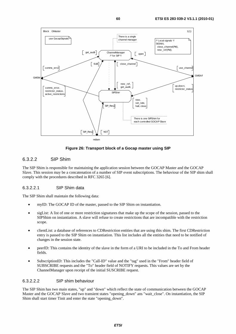
ETSI
ETSI ES 283 039-2 V3.1.1 (2010-01)60
There is one SIPShim foreach controlled GOCAP Slave
There is a singlechannel manager
SUB
1(1)
/* Local signals */SIGNAL close_channel(PId), new _ref(PId);
get_audit
comms_error
ChannelManager/* for SIP */
SIPShim
up,dow n,restrictor_status
GMSAP
new _ref,get_audit,
close_channel
use GocapSignals;
new , set_rate,halt, close
use_channel
open
NOT
mdiam
SIP_Resp
comms_error,restrictor_status,active_restrictions
GMSM
SIP_Resp
Block GMaster
Figure 26: Transport block of a Gocap master using SIP
6.3.2.2 SIP Shim
The SIP Shim is responsible for maintaining the application session between the GOCAP Master and the GOCAP Slave. This session may be a concatenation of a number of SIP event subscriptions. The behaviour of the SIP shim shall comply with the procedures described in RFC 3265 [6].
6.3.2.2.1 SIP Shim data
The SIP Shim shall maintain the following data:
• myID: The GOCAP ID of the master, passed to the SIP Shim on instantiation.
• sigList: A list of one or more restriction signatures that make up the scope of the session, passed to the SIPShim on instantiation. A slave will refuse to create restrictions that are incompatible with the restriction scope.
• clientList: a database of references to CDRestriction entities that are using this shim. The first CDRestriction entry is passed to the SIP Shim on instantiation. This list includes all the entities that need to be notified of changes in the session state.
• peerID: This contains the identity of the slave in the form of a URI to be included in the To and From header fields.
• SubscriptionID: This includes the "Call-ID" value and the "tag" used in the "From" header field of SUBSCRIBE requests and the "To" header field of NOTIFY requests. This values are set by the ChannelManager upon receipt of the initial SUSCRIBE request.
6.3.2.2.2 SIP shim behaviour
The SIP Shim has two main states, "up" and "down" which reflect the state of communication between the GOCAP Master and the GOCAP Slave and two transient states "opening_down" ans "wait_close". On instantiation, the SIP Shim shall start timer Tinit and enter the state "opening_down".

ETSI
ETSI ES 283 039-2 V3.1.1 (2010-01)61
The behaviour of the SIP Shim in each state shall be as follows:
In state "opening_down":
• It shall send a down signal in response to any new, set_rate or halt signals received from a CDRestriction.
• It shall add the details of any new CDRestriction it receives via a new_ref signal to its clientList.
• If Tinit expires, the SIP Shim shall start timer Tguard, send a comms_error(TimeoutTinit) signal to the management and enter the state "down".
• If a SUBSCRIBE request is received, the SIP shim shall:
- If the Expires header field is greater than zero, stop timer Tinit, send an "up" signal to each of the CDRestrictions in the clientList and enter state "up" and request the Channel Manager to generate a "200 OK" response to the SUBSCRIBE request with the following settings:
� an Expires header field, set to either the same or a decreased value as the Expires header field in SUBSCRIBE request; and
� the Contact header field set to an identifier uniquely associated to the SUBSCRIBE request and generated within the GOCAP master, that may help the GOCAP master to correlate refreshes for the subscription.
- If the Expires header field is equal to zero, the SIP shim shall request the Channel Manager to return a 200 OK response, send a comms_error(abnormalEvent) signal to the management, start timer Tguard and enter the state "down".
• If a close signal is received, remove the sender from the clientList and, if the client list is now empty, the SIP shim shall start time Tclose and enter the "wait_close" state.
In state "down":
• It shall send a down signal in response to any new, set_rate or halt signals received from a CDRestriction.
• It shall add the details of any new CDRestriction it receives via a new_ref signal to its clientList.
• If Tguard expires, the SIP Shim shall start time Tclose and enter the "wait_close" state.
• If a SUBSCRIBE request is received, the SIP shim shall:
- If the Expires header field is greater than zero, stop timer Tinit, send an "up" signal to each of the CDRestrictions in the clientList, start timer Tsub, enter state "up" and request the Channel Manager to generate a "200 OK" response to the SUBSCRIBE request with the following settings:
� an Expires header field, set to either the same value as the Expires header field in the SUBSCRIBE request or to Tsub if the received value is greater than Tsub; and
� the Contact header field set to an identifier uniquely associated to the SUBSCRIBE request and generated within the GOCAP master, that may help the GOCAP master to correlate refreshes for the subscription.
- If the Expires header field is equal to zero, the SIP shim shall request the Channel Manager to return a 200 OK response, send a comms_error(abnormalEvent) signal to the management, start timer Tguard and enter the state "down".
• If a close signal is received, remove the sender from the clientList and, if the client list is now empty, the SIP shim shall start time Tclose and enter the "wait_close" state.
In state "up":
• Handle new, set_rate, halt and audit signals as described in clause 5.3.3.3.
• When a 200 OK response to a NOTIFY request arrives, the Gocap Shim shall extract the message body and, for each of the entries in the responseList element, send a restrictor_status(rid, status) signal to the relevant CDRestrictor.

ETSI
ETSI ES 283 039-2 V3.1.1 (2010-01)62
• It shall add the details of any new CDRestriction it receives via a new_ref signal to its clientList and send an up signal to that CDRestriction.
• If Tsub expires, the SIP Shim shall set timer Tguard, send a down signal to each of the CDRestrictions in its clientList and enter the state "down".
• If a non 200-class response to a NOTIFY request is received with a retry-after header field, the SIP Shim shall resend the request after the specified time.
• If a SUBSCRIBE request with the Expires header field is set to zero is received, the SIP Shim shall send a down signal to each of the CDRestrictions in its clientList, request the Channel Manager to send a 200 OK response to the slave, set timer Tguard and enter state "down".
• If a close signal is received, remove the sender from the clientList and, if the client list is now empty, the SIP shim shall timer Tguard, send a NOTIFY request with the "Subscription-State" header field set to "terminated", start timer Tclose and enter the state "wait_close".
In state "wait_close":
• On expiry of Tclose, the SIPShim shall terminate.
• On receipt of a 200 OKresponse to a NOTIFY request the SIPShim shall terminate.
• If the NOTIFY request fails (as defined in RFC 3265 [6]) the SIP shim shall send a comms_error(unableToClose) signal to the management and shall terminate.
• If a non 200-class response with a retry-after header is received, the SIP shim shall resend the request after the specified time and restart time Tclose.
6.3.2.2.3 Generating NOTIFY messages
NOTIFY messages carry GOCAP commands (new, set_rate, halt and audit) between Master and Slave. A NOTIFY request may contain more than one command and so there are two possibilities open to an implementation; send one NOTIFY request for each individual new, set_rate, halt or audit request it receives or send one NOTIFY request containing data for multiple Gocap request. The first option is simplest but, because a Gocap Master may have multiple restrictions on the same slave, generating one SIP request per restriction every time the Control Distribution updates may be an unacceptable waste of resources. The solution is to define a flag, building, which is false unless the SIP shim is currently assembling data for a NOTIFY request. When the flag is true, gocap requests will be cached until a timer expires, at which point to NOTIFY request containing one or more gocap commands is sent and the building flag is set to false.
There is no problem with sending multiple commands in the same NOTIFY request if the commands are for different restrictions. If there are multiple commands for a single restriction however, there may be an issue as there is no explicit ordering of individual commands within a single NOTIFY request. This is solved by using the actions described in Table 12 (those marked "N/A" are message combinations that cannot occur).
Table 12: Handling multiple requests with the same restriction ID
Initial command
Subsequent command
Safe Actions
New Any N/A Set_rate New N/A Set_rate set_rate Replace the initial command with the subsequent command. Set_rate Halt Replace the set_rate with the halt. Halt New Immediate despatch of the NOTIFY containing the halt request and putting the new
request in the next NOTIFY (see note). Halt set_rate N/A Halt Halt N/A NOTE: In principle we could replace the halt with the new, but the new may fail (e.g. due to scope violation) thus
leaving the original restriction in place. Triggering immediate despatch of the NOTIFY with halt and putting the new in the next NOTIFY is the only safe solution.

ETSI
ETSI ES 283 039-2 V3.1.1 (2010-01)63
The behaviour of the SIP Shim in states "up" shall be as follows:
When a new, set_rate, halt or audit signal is received and the building flag false is false then theSIP Shim shall:
• Set the building flag to true.
• Set the timer T15.
• Cache the signal data.
When a new, set_rate, haltor audit signal is received and the building flag is true then the SIP Shim shall:
• if the new request does not have the same restriction ID as a cached one or is an audit request, add it to the cached requests;
• if the new request has the same restriction ID as a cached one and Table 12 allows replacement, replace the cached request with the new request;
• if the new request has the same restriction ID as a cached one and Table 12 does not allow replacement, generate the NOTIFY request data based on the cached data and send to the slave, set timer T11, move the cached request data to the messageDatabase indexed via the NOTIFY request End-to-End Identifier , set timer T15 and cache the new request;
• if the timer T15 expires, generate the NOTIFY request data based on the cached data and send to the slave, set timer T11, set building flag to false and move the cached request data to the messageDatabase, indexed via the NOTIFY request End-to-End Identifier.
Generating the NOTIFY request from the cached results is a straightforward mapping of the data in the requests to the per request data elements described in the XML document to be included in the message body.
The SIP shim shall then wait for a response to the NOTIFY request. If the NOTIFY request fails (as defined in RFC 3265 [6]) the SIP shim shall enter the "down" state. If a non 200-class response with a retry-after header is received, the SIP shim shall resend the request after the specified time.
6.3.3 GOCAP slave
6.3.3.1 SIP Listener
The SIPGocapListener listens for SIP messages which are destined for that GOCAP Slave, see Figure 27. It is responsible for instantiating SIP Session Handlers to process messages between SIP and the Restrictor Manager. Each SIP Session Handler represents a SIP dialogue. The SIP Listener maintains a database of SIP Session Handlers which it can search on the basis of Call-ID, To or From header fields. It shall also keep track of the scope of each current session.
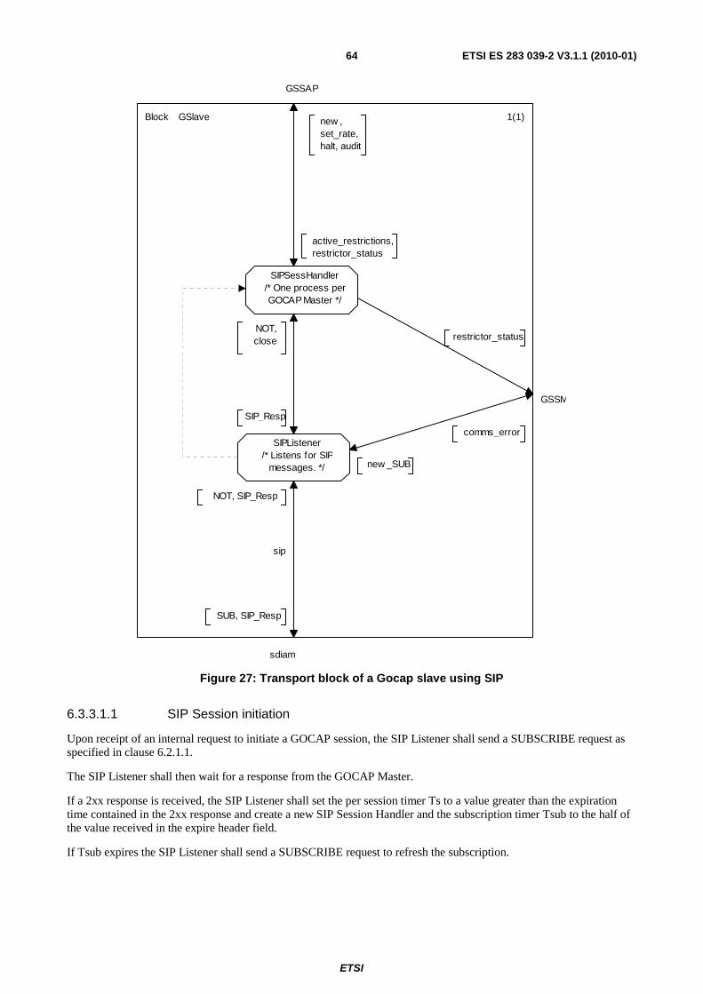
ETSI
ETSI ES 283 039-2 V3.1.1 (2010-01)64
new _SUB
comms_error
GSSM
restrictor_status
active_restrictions,restrictor_status
GSSAP
new , set_rate,halt, audit
SIP_Resp
NOT,close
NOT, SIP_Resp
sdiam
sip
SUB, SIP_Resp
1(1)
SIPListener/* Listens for SIP
messages. */
SIPSessHandler/* One process perGOCAP Master */
Block GSlave
Figure 27: Transport block of a Gocap slave using SIP
6.3.3.1.1 SIP Session initiation
Upon receipt of an internal request to initiate a GOCAP session, the SIP Listener shall send a SUBSCRIBE request as specified in clause 6.2.1.1.
The SIP Listener shall then wait for a response from the GOCAP Master.
If a 2xx response is received, the SIP Listener shall set the per session timer Ts to a value greater than the expiration time contained in the 2xx response and create a new SIP Session Handler and the subscription timer Tsub to the half of the value received in the expire header field.
If Tsub expires the SIP Listener shall send a SUBSCRIBE request to refresh the subscription.
ETSI
ETSI ES 283 039-2 V3.1.1 (2010-01)65
6.3.3.1.2 Session termination
At the slave, a session may be terminated in three ways:
• A NOTIFY request with the "Subscription-State" header field set to "terminated"is received from the Gocap Master.
• The timer Ts expires.
• Management action.
When a NOTIFY request with the "Subscription-State" header field set to "terminated" is received, the SIP Listener shall:
• send an 200 OK response to the Master;
• send a close signal to the SIP Session Handler handling the specified session if it exists; and
• delete the data relating to the session and release any scope granted to the session.
When the timer Ts expires, the SIP Listener shall:
• Locate the data associated with the session to which Ts belongs.
• Send an SUBSCRIBE request with the Expires header field is set to zero to the Gocap Master.
• On receipt of a 2XX response from the GOCAP master, send a close to the SIP Session Handler handling the session.
6.3.3.1.3 Gocap commands
The Gocap commands, new, set_rate, halt and audit are transported in NOTIFY messages. When a NOTIFY message arrives at the SIP Listener, it shall verify that it corresponds to an active subscription. If the subscription is known and valid, the NOTIFY message shall be passed to the session handler for that dialogue, otherwise the SIP Listener shall send an appropriate SIP 400- or 500-class response as specified in RFC 3265 [6].
6.3.3.2 SIP Session Handler
The SIP Session Handler is responsible for extracting the Gocap commands from NOTIFY messages and collating the results, see Figure 27. The SIP Session Handler is instantiated by the SIP Listener when the SIP dialogue between the master and the slave is initiated. On instantiation, the SIP session handler is proved with a list of valid signature scopes and the Master GocapID appropriate to the dialogue.
When a NOTIFY message arrives at the session handler it shall:
• Parse the XML body to extract the requestList and the GOCAP ID of the Master.
• Initialise XML data for the responseList.
• For each new restriction request in the newRestrictions element of the XML requestList:
a. Build a Restriction data structure.
b. Verify that the restrictor signatures are within the scope for this session.
c. If the restriction request is in scope, use the extracted data to send a new signal to the restrictor manager; capturing the resulting restrictor_status signal to generate data for the ResponseList.
d. Update the response list entry for this request.
• For each leak rate update request in the restrictionUpdates element of the XML requestList:
a. Build a new_rate(i RestrictionID, r Leakrate) signal from the XML data.
b. Send the new_rate signal to the restrictor manager.

ETSI
ETSI ES 283 039-2 V3.1.1 (2010-01)66
c. Capture the resulting restrictor_status signal and update the response list entry for this request.
• For each restrictor deletion request in the deletions element of the XML requestList:
a. Build a halt(i RestrictionID) signal from the XML data.
b. Send the halt signal to the restrictor manager.
c. Capture the resulting restrictor_status signal and update the response list entry for this request.
• Generate the XML body for the 200 OK response using the response list data generated.
If a new_sigs signal is received by the SIP Session Handler, then the local list of valid signature scopes is replaced by those contained in the new_sigs signal.
If a close signal is received by the SIP Session Handler then it shall:
• send an audit signal to the restrictor manager, specifying the GocapID of the Gocap Master for this session;
• wait for the resulting restriction_list signal;
• for each restriction in the restriction list, extract the restriction ID, i, and send a halt(i) signal to the Restrictor Manager; and terminate.

ETSI
ETSI ES 283 039-2 V3.1.1 (2010-01)67
Annex A (normative): ASN.1 data types and signal definitions
A.1 ASN.1 definitions GOCAPID ::= Octetstring; -- TBD after advice from NN&A experts -- How about a FQDN? How would that interact -- with DNS based load balancing? Address ::= Octetstring; -- TBD after advice from NN&A experts AddressList::=SEQUENCE OF Address ; TransportType::=ENUMERATED{UDP,TCP,SCTP,...}; ApplicationAddress ::= Octetstring; -- As above - this needs NN&A input. -- Expect a contitional type depending on -- the ApplicationAddressType. ApplicationAddressType ::= ENUMERATED { pstn, uriFqdn, uriIP, ip, ... }; ApplicationLabel ::= Visiblestring; -- The legal content of this string will be -- defined in the relevant shim spec - expect -- things like "SIP" or "SIP.INVITE" RestrictionType ::= ENUMERATED { floatingPointLeakyBucket, ... }; RestrictionID ::= SEQUENCE { master GOCAPID, num Integer }; ShimType ::= ENUMERATED { local, diameter, sip_sub_not, ... }; Leakrate ::= Real ; Signature ::= SEQUENCE { appSrcs SEQUENCE OF Address, -- The IP addresses of source(slave) as -- understood by the applications on the -- host on which the restrictor is being -- created. appDests SEQUENCE OF Address, -- The IP addresses of destination(master) as -- understood by the applications on the host -- on which the restrictor is being created. appLabel ApplicationLabel, -- e.g. "SIP" or "SIP.REGISTER" etc appAddrs SEQUENCE OF ApplicationAddress, -- A list of application layer addresses, e.g. -- SIP URIs, phone numbers. Some addresses may -- wildcarded e.g. "*.bt.com" addrType ApplicationAddressType -- Type of application address - needed for -- address handing and for wildcard rules that -- apply to that address type.

ETSI
ETSI ES 283 039-2 V3.1.1 (2010-01)68
}; AuthScopeList ::= SEQUENCE OF Signature; Flows ::= SEQUENCE OF SEQUENCE { splash Real, signature Signature }; Restriction ::= SEQUENCE { resID RestrictionID, flows Flows, duration Duration, -- Duration of control - if control -- not updated in this interval, delete it. -- The purpose of the parameter is -- to prevent restrictons being created and -- then forgotten - i.e. never removed. -- NB We restrict the range of intervals to be -- at least 1 minute but no more than 2 days. restrictionType RestrictionType , leakrate Leakrate }; RestrictionList ::= SEQUENCE OF Restriction; /* ProcSet ::= SET OF PId; */ newtype ProcSet Powerset(PId) adding operators take : ProcSet -> PId; /* get an element of the set */ endnewtype; SourceData ::= SEQUENCE { addrs AddressList, -- of the GOCAP slave flows Flows, shim ShimType, w Real, s Real, rType RestrictionType, duration Duration, static Boolean }; RestrictionStatus ::= ENUMERATED { ok, -- The restriction is OK invalidGOCAPID, -- The GOCAP Comms Channel does not exist scopeViolation, -- The scope of the restriction is not -- appropriate invalidAddressType, -- The address type is not one the slave -- recognises invalidType, -- The restriction type is invalid internalError, -- The host has run out of memory etc. invalidID, -- The restrictor ID is invalid unknownID -- The restrictor ID has not been created }; CommsError ::= ENUMERATED { invalidGOCAPID, unknownTransport, linkDown, heartbeatLost -- There has been a heartbeat reply missed. }; RequestPriority ::= Integer(0..15); PriorityList ::= SEQUENCE (0..15) OF Real;

ETSI
ETSI ES 283 039-2 V3.1.1 (2010-01)69
/* A list of splash:restriction pairs, used by the restriction search procedure */ ApplicableRestrictors ::= SEQUENCE { cnt Integer(0..65534), list SEQUENCE OF SEQUENCE { restrictor PId, splash Real } };
A.2 Signals SIGNAL open(AddressList, /* The GOCAP address list */ ShimType ), /* How master and slave communicate */ newRef, /* signal used to maintain the reference count for the message handlers*/ comms_error( AddressList, /* How we refer to this connection */ ShimType, CommsError ), /* The actual problem */ use_channel( PId), /* the ID of the channel process */ close_channel(chanID PId), /*scope(DiameterSessionID, /* How we refer to this connection */ /* Signature), /* List of restrictions sigs that match me */ add_src(SourceData), update_src(id Integer, s Real, /* The capacity allocated to this source */ w Real ), /* The proportion of free capacity to give to this source */ del_src(Integer), create_r ( Restriction ), restrictor_status( RestrictionID, /* The restriction in question */ RestrictionStatus ), /* The problem */ CDRestriction_error( PId, /* The CDRestriction in question */ RestrictionStatus ), /* The problem */ set_rate( RestrictionID, /* restriction serial number */ Leakrate ), /* New leakrate for restrictor */ halt(RestrictionID),/* restriction serial number */ close, /* close a channel between Master and Slave */ add_listener( GOCAPID, /* Slave node ID */ AddressList), /* Address:ports to listen on */ get_audit(AddressList,ShimType,PId), audit(GOCAPID), active_restrictions(RestrictionList), new_ref(PId), new(Restriction), glr_update( Real, /* The new global leak rate (control variable) */ Real) , /* The capacity factor */ request(sig Signature, /* The signature of the application level request */ p RequestPriority) , /* The request priority (set by application) */ admit, reject; /* GOCAP responses to request message */ SIGNAL /* Used by system to update the Control Adaptor */ system_state(Real, /* The actual arrival rate of work into the system */ Real), /* The goal arrival rate */

ETSI
ETSI ES 283 039-2 V3.1.1 (2010-01)70
/* Used by the Control Distribution to update the SLA allocation in the CA. */ update_origin(S Real, /* The total capacity guarantees offered by the system */ R Real), /* Smallest s/w ratio source managed by the CD */ /* to switch the control off - from CA to CD */ terminate, /* Signals from RMProcess to restrictors */ test(Real,RequestPriority), update(Leakrate), delete, confirm(Real), /* Restrictor responses */ ok,fail,expired(PId,RestrictionID); SIGNAL update_CDR(Leakrate), halt_CDR, delete_CDR, CDR_Id(Integer), CDR_error(Integer, RestrictionStatus), up, down;
A.3 SDL description The current draft of the SDL description is contained in archive es_28303902v030101p0.zip which accompanies the present document.
NOTE: The file GOCAP_xxx_2_4_4a.cbf is in the binary format of Cinderela SDL.

ETSI
ETSI ES 283 039-2 V3.1.1 (2010-01)71
Annex B (normative): Congestion_Control event package
B.1 Event Package Name The name of this package is "congestion_control". As defined in RFC 3265 [6], this value appears in the Event header field present in SUBSCRIBE and NOTIFY requests for this package.
B.2 Event Package Parameters No parameters are defined for this event package.
B.3 SUBSCRIBE Bodies This package defines no use of the SUBSCRIBE request body. If present, it shall be ignored.
B.4 Subscription Duration The duration of a subscription is specific to SIP deployments and no specific recommendation is made by this Event Package.
B.5 NOTIFY Bodies The NOTIFY body shall contain overload control information. The package specification does not mandate any specific contents and syntax for overload control information. The overload control information to be carried depends on the overload control mechanism in use.
The NOTIFY body shall include a content corresponding to a MIME type specified in the 'Accept' header of the SUBSCRIBE.
B.6 Notifier Processing of SUBSCRIBE Requests A successful SUBSCRIBE request results in a NOTIFY. The SUBSCRIBE request for the overload control event should be either authenticated or transmitted over an integrity protected SIP communication channels.
If the identity of the entity sending the SUBSCRIBE message is not allowed to receive overload control information, the notifier shall return a 403 "Forbidden" response.
If none of MIME types specified in the Accept header of the SUBSCRIBE is supported, the Notifier should return 406 "Not Acceptable" response.
B.7 Notifier Generation of NOTIFY Requests As specified in RFC 3265 [6], the Notifier shall always send a NOTIFY request upon accepting a subscription. Depending on the used overload control mechanism, this may contain a body. For instance, if the overload mechanism is based on reporting the load status, the first NOTIFY should contain a body reporting the current load status.

ETSI
ETSI ES 283 039-2 V3.1.1 (2010-01)72
If the SUBSCRIBE was received over an integrity protected SIP communications channel, the Notifier should send the NOTIFY over the same channel.
If an Accept header was received in the SUBSCRIBE message, the body type of the NOTIFY request shall correspond to one of the ones that were indicated in this header.
B.8 Subscriber Processing of NOTIFY Requests Upon receipt of a NOTIFY request with a Subscription-State header field containing the value "terminated", the subscriber shall remove all previously received load control information and process all calls without applying any restriction.
The subscriber shall discard unknown bodies. If the NOTIFY request contains several bodies, none of them being supported, it should unsubscribe. A NOTIFY request that does not contain a body shall be ignored.
The way subscribers process supported bodies depends on the overload mechanism in use.
B.9 Subscriber Generation of SUBSCRIBE Requests The subscribe message shall contain the Event header set to "congestion_control" and the Accept header indicating the supported MIME types.
B.10 Handling of Forked Requests This Event package allows the creation of only one dialog as a result of an initial SUBSCRIBE request as described in section 4.4.9 of RFC 3265 [6]. It does not support the creation of multiple subscriptions using forked SUBSCRIBE requests.
B.11 Rate of Notifications The rate of notifications for overload control information will depend on the overload mechanism in use. Hence, the event package specification does not specify a throttling or minimum period between NOTIFY requests.
B.12 State Agents State agents are not applicable to this Event Package.
B.13 Use of URIs to Retrieve State This Event package does not make use of URIs to retrieve state information.
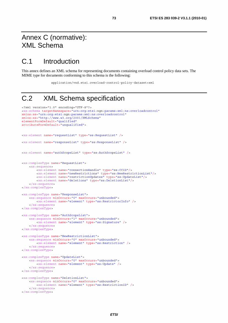
ETSI
ETSI ES 283 039-2 V3.1.1 (2010-01)73
Annex C (normative): XML Schema
C.1 Introduction This annex defines an XML schema for representing documents containing overload control policy data sets. The MIME type for documents conforming to this schema is the following:
application/vnd.etsi.overload-control-policy-dataset+xml
C.2 XML Schema specification <?xml version="1.0" encoding="UTF-8"?> <xs:schema targetNamespace="urn:org:etsi:ngn:params:xml:ns:overloadcontrol" xmlns:ss="urn:org:etsi:ngn:params:xml:ns:overloadcontrol" xmlns:xs="http://www.w3.org/2001/XMLSchema" elementFormDefault="qualified" attributeFormDefault="unqualified"> <xs:element name="requestList" type="ss:RequestList" /> <xs:element name="responseList" type="ss:ResponseList" /> <xs:element name="authScopeList" type="ss:AuthScopeList" /> <xs:complexType name="RequestList"> <xs:sequence> <xs:element name="connectionHandle" type="ss:CCID"/> <xs:element name="newRestrictions" type="ss:NewRestrictionList"/> <xs:element name="restrictionUpdates" type="ss:UpdateList"/> <xs:element name="deletions" type="ss:DeletionList"/> </xs:sequence> </xs:complexType> <xs:complexType name="ResponseList"> <xs:sequence minOccurs="0" maxOccurs="unbounded"> <xs:element name="element" type="ss:RestrictorInfo" /> </xs:sequence> </xs:complexType> <xs:complexType name="AuthScopeList"> <xs:sequence minOccurs="1" maxOccurs="unbounded"> <xs:element name="element" type="ss:Signature" /> </xs:sequence> </xs:complexType> <xs:complexType name="NewRestrictionList"> <xs:sequence minOccurs="0" maxOccurs="unbounded"> <xs:element name="element" type="ss:Restriction" /> </xs:sequence> </xs:complexType> <xs:complexType name="UpdateList"> <xs:sequence minOccurs="0" maxOccurs="unbounded"> <xs:element name="element" type="ss:Update" /> </xs:sequence> </xs:complexType> <xs:complexType name="DeletionList"> <xs:sequence minOccurs="0" maxOccurs="unbounded"> <xs:element name="element" type="ss:RestrictionID" /> </xs:sequence> </xs:complexType>
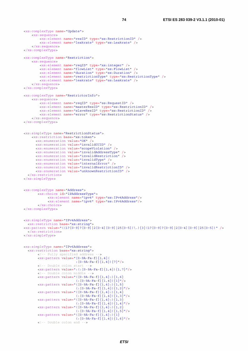
ETSI
ETSI ES 283 039-2 V3.1.1 (2010-01)74
<xs:complexType name="Update"> <xs:sequence> <xs:element name="resID" type="ss:RestrictionID" /> <xs:element name="leakrate" type="ss:Leakrate" /> </xs:sequence> </xs:complexType> <xs:complexType name="Restriction"> <xs:sequence> <xs:element name="reqID" type="xs:integer" /> <xs:element name="flowList" type="ss:FlowList" /> <xs:element name="duration" type="ss:Duration" /> <xs:element name="restrictionType" type="ss:RestrictionType" /> <xs:element name="leakrate" type="ss:Leakrate" /> </xs:sequence> </xs:complexType> <xs:complexType name="RestrictorInfo"> <xs:sequence> <xs:element name="reqID" type="ss:RequestID" /> <xs:element name="masterResID" type="ss:RestrictionID" /> <xs:element name="slaveResID" type="ss:RestrictionID" /> <xs:element name="error" type="ss:RestrictionStatus" /> </xs:sequence> </xs:complexType> <xs:simpleType name="RestrictionStatus"> <xs:restriction base="xs:token"> <xs:enumeration value="OK" /> <xs:enumeration value="invalidCCID" /> <xs:enumeration value="scopeViolation" /> <xs:enumeration value="invalidAddressType" /> <xs:enumeration value="invalidRestriction" /> <xs:enumeration value="invalidType" /> <xs:enumeration value="internalError" /> <xs:enumeration value="invalidRestrictionID" /> <xs:enumeration value="unknownRestrictionID" /> </xs:restriction> </xs:simpleType> <xs:complexType name="Address"> <xs:choice id="IPAddressType"> <xs:element name="ipv4" type="ss:IPv4Address"/> <xs:element name="ipv6" type="ss:IPv6Address"/> </xs:choice> </xs:complexType> <xs:simpleType name="IPv4Address"> <xs:restriction base="xs:string"> <xs:pattern value="((1?[0-9]?[0-9]|2[0-4][0-9]|25[0-5])\.){3}(1?[0-9]?[0-9]|2[0-4][0-9]|25[0-5])" /> </xs:restriction> </xs:simpleType> <xs:simpleType name="IPv6Address"> <xs:restriction base="xs:string"> <!-- Fully specified address --> <xs:pattern value="[0-9A-Fa-f]{1,4}( :[0-9A-Fa-f]{1,4}){7}"/> <!-- Double colon start --> <xs:pattern value=":(:[0-9A-Fa-f]{1,4}){1,7}"/> <!-- Double colon middle --> <xs:pattern value="([0-9A-Fa-f]{1,4}:){1,6} (:[0-9A-Fa-f]{1,4}){1}"/> <xs:pattern value="([0-9A-Fa-f]{1,4}:){1,5} (:[0-9A-Fa-f]{1,4}){1,2}"/> <xs:pattern value="([0-9A-Fa-f]{1,4}:){1,4} (:[0-9A-Fa-f]{1,4}){1,3}"/> <xs:pattern value="([0-9A-Fa-f]{1,4}:){1,3} (:[0-9A-Fa-f]{1,4}){1,4}"/> <xs:pattern value="([0-9A-Fa-f]{1,4}:){1,2} (:[0-9A-Fa-f]{1,4}){1,5}"/> <xs:pattern value="([0-9A-Fa-f]{1,4}:){1} (:[0-9A-Fa-f]{1,4}){1,6}"/> <!-- Double colon end -->

ETSI
ETSI ES 283 039-2 V3.1.1 (2010-01)75
<xs:pattern value="([0-9A-Fa-f]{1,4}:){1,7}:"/> <!-- Embedded IPv4 addresses --> <xs:pattern value="((:(:0{1,4}){0,3}(:(0{1,4}| [fF]{4}))?)|(0{1,4}:(:0{1,4}){0,2} (:(0{1,4}|[fF]{4}))?)|((0{1,4}:) {2}(:0{1,4})?(:(0{1,4}|[fF]{4}))?) |((0{1,4}:){3}(:(0{1,4}|[fF]{4}))?) |((0{1,4}:){4}(0{1,4}|[fF]{4})?)): (25[0-5]|2[0-4][0-9]|[0-1]?[0-9]?[0-9]) \.(25[0-5]|2[0-4][0-9]|[0-1]?[0-9]? [0-9])\.(25[0-5]|2[0-4][0-9]|[0-1]? [0-9]?[0-9])\.(25[0-5]|2[0-4][0-9]| [0-1]?[0-9]?[0-9])"/> <!-- The unspecified address --> <xs:pattern value="::"/> </xs:restriction> </xs:simpleType> <xs:simpleType name="ApplicationAddress"> <xs:annotation> <xs:documentation> Application layer address, e.g. SIP URI, phone number. Some addresses may be wildcarded using a delimited regular expression. The regular expression shall take the form of Extended Regular Expressions (ERE) as defined in chapter 9 in IEEE 1003.1-2004 Part 1 [60]. The delimiter shall be the exclamation mark character ("!"). </xs:documentation> </xs:annotation> <xs:restriction base="xs:string" /> </xs:simpleType> <xs:simpleType name="ApplicationAddressType"> <xs:restriction base="xs:token"> <xs:enumeration value="pstn" /> <xs:enumeration value="uriFqdn" /> <xs:enumeration value="uriIP" /> <xs:enumeration value="ip" /> </xs:restriction> </xs:simpleType> <xs:simpleType name="ApplicationLabel"> <xs:restriction base="xs:string" /> </xs:simpleType> <!-- The legal content of this string will be defined in the relevant shim spec expect things like "SIP" or "SIP.INVITE" --> <xs:simpleType name="RestrictionType"> <xs:union memberTypes="xs:token"> <xs:simpleType> <xs:restriction base="xs:token"> <xs:enumeration value="floatingPointLeakyBucket" /> </xs:restriction> </xs:simpleType> </xs:union> </xs:simpleType> <xs:simpleType name="Leakrate"> <xs:restriction base="xs:double" /> </xs:simpleType> <xs:complexType name="AddressList"> <xs:sequence minOccurs="0" maxOccurs="unbounded"> <xs:element name="element" type="ss:Address" /> </xs:sequence> </xs:complexType> <xs:complexType name="CCID"> <xs:sequence> <xs:element name="masterID" type="ss:GOCAPID" /> <xs:element name="slaveID" type="ss:GOCAPID" /> </xs:sequence> </xs:complexType>

ETSI
ETSI ES 283 039-2 V3.1.1 (2010-01)76
<xs:simpleType name="RestrictionID"> <xs:restriction base="xs:integer" /> </xs:simpleType> <xs:simpleType name="GOCAPID"> <xs:restriction base="xs:string" /> </xs:simpleType> <xs:complexType name="Flow"> <xs:sequence> <xs:element name="signature" type="ss:Signature" /> <xs:element name="splash" type="xs:double" /> </xs:sequence> </xs:complexType> <xs:complexType name="Signature"> <xs:sequence> <xs:element name="appSrcs"> <xs:annotation> <xs:documentation> The IP addresses of source(slave) as understood by the applications on the host on which the restrictor is being created. </xs:documentation> </xs:annotation> <xs:complexType> <xs:sequence minOccurs="1" maxOccurs="unbounded"> <xs:element name="element" type="ss:Address" /> </xs:sequence> </xs:complexType> </xs:element> <xs:element name="appDests"> <xs:annotation> <xs:documentation> The IP addresses of destination(master) as understood by the applications on the host on which the restrictor is being created. </xs:documentation> </xs:annotation> <xs:complexType> <xs:sequence minOccurs="1" maxOccurs="unbounded"> <xs:element name="element" type="ss:Address" /> </xs:sequence> </xs:complexType> </xs:element> <xs:element name="appLabel" type="ss:ApplicationLabel" /> <xs:element name="appAddrs"> <xs:complexType> <xs:sequence minOccurs="0" maxOccurs="unbounded"> <xs:element name="element" type="ss:ApplicationAddress" /> </xs:sequence> </xs:complexType> </xs:element> <xs:element name="addrType" type="ss:ApplicationAddressType" /> </xs:sequence> </xs:complexType> <xs:complexType name="FlowList"> <xs:sequence minOccurs="1" maxOccurs="unbounded"> <xs:element name="element" type="ss:Flow" /> </xs:sequence> </xs:complexType> <xs:simpleType name="Duration"> <xs:restriction base="xs:integer"/> </xs:simpleType> <xs:simpleType name="RequestID"> <xs:restriction base="xs:integer"/> </xs:simpleType> </xs:schema>

ETSI
ETSI ES 283 039-2 V3.1.1 (2010-01)77
Annex D (informative): Generating System_state data
D.1 Introduction The description of the GOCAP behaviours in clause 4 assume that the application/operating system provide GOCAP with two key pieces of data via the system_state signal, the current workload arrival rate and the target arrival rate. Driving the GOCAP adaptation algorithm from these two metrics enables GOCAP to adapt very quickly. The generation of these parameters is not a normative part of the GOCAP specification as it depends on the application behaviour and the server architecture.
Some applications always show very little variation in the processing time per request. In these cases the goal arrival rate may simply be a configurable parameter which is normally left constant. Performance testing would determine the best value. However there are risks with this approach, e.g. CPUs can fail and therefore if failure cannot be detected automatically a sudden reduction in capacity would result without a corresponding reduction in the goal rate. The risk can be reduced by setting a rate which assumes that one fewer CPUs is available, but clearly this does not allow the available capacity to be fully utilised.
Some servers support multiple applications or applications where the processing time per request varies significantly between different requests however, and in these cases the target arrival rate will need to be recalculated continuously so as to reflect changes in the mix of request types or request complexity in real time. In the following clauses some of the issues that this calculation raises are discussed and a particular solution based on a continuous estimate of the work per request is presented.
D.2 Background GOCAP aims to control overload of processing resources within a server. Let each request (e.g. call) imply occupying the processing resource for a mean timeτ, then we have according to Little's Law:
τΛ=D (D.1)
where D is the total workload demand and Λ is the mean arrival rate, after any restrictive control has been applied. If the number of servers (e.g. CPUs) is M, and we have a goal occupancy (due to requests) of Ω* (usually a configurable parameter), then:
** DM =Ω (D.2)
is the goal workload rate; and
** D=Λ τ (D.3)
gives the goal arrival rate, *Λ . However, τ may change depending upon the request mix (i.e. relative numbers of requests of different complexity) and hence Λ also has a dependence upon the mix. We will show a way to measure the mean CPU time per request, τ/M, and the mean arrival rate Λ hence derive the goal rate Λ*.
When there is sufficient demand GOCAP's adaptation algorithm converges to the above solutions, distributing the workload between each source i with rate λi so that:
∑ ∑ == *Dd iii τλ (D.4)

ETSI
ETSI ES 283 039-2 V3.1.1 (2010-01)78
The mean processing timeτi for source i is almost always unknown at the source itself, although sometimes the expected processing effort for each request may be estimated according to its identified request type. This variation of processing time may (or may not) be factored in using the splash weight pi of the leaky bucket restrictor since the maximum throughput of the bucket satisfies:
i
ii p
r=λ (D.5)
where ri is the leak rate of the bucket and pi/ri represents the time τi.
NOTE: The GOCAP restrictor specification in clause 4.2.6.1 allows different request types to be recognised, using the request signatures. A different splash value may apply to each signature. The splash can be thought of as relating request processing effort for that request type and is proportional to 1/τ .
D.3 Modelling CPU load The simplest model of the dependence of CPU utilisation upon arrival rate at constant mix (request complexity) would be linear through the origin (zero occupancy at an arrival rate of zero). However a background/admin load that is independent of request arrival rate is usually present, which can be relatively large, so a better model is linear with non-zero occupancy at zero arrival rate. Furthermore CPU utilisation can be quadratic as a function of request rate, this quadratic behaviour being due to a dependence upon context holding time, although the 'quadratic term' is small when the context holding time is small in which case the relationship then looks almost linear.
call arrival rate
CPU occupancy
goal
(target)
occupancy
Figure D.1: Convergence of adaptation (linear CPU dependence with non-zero intercept at 0 arrival rate, mix constant)
From the viewpoint of ensuring 'convergence' to the specified CPU threshold these models of varying complexity do not matter, although they can affect the rate of convergence. It is adequate to assume the simplest model, which just requires computing the average CPU time per request (Figure D.1 shows the linear dependence case). This is just as well, since it may not easy to identify which processes have the request rate dependence. However faster convergence can be obtained if the background/admin occupancy can be separately measured (in real-time), or if not, a configurable constant is included to represent the occupancy at a request rate of zero. Similar considerations apply if the true relationship is quadratic, although the theoretically convergence is then not monotonic (see Figure D.2).
NOTE: Monotonic convergence is purely increasing from below the goal (or decreasing from above it). In practice, due to stochastic variation and changing goal rates, convergence can always oscillate between above and below the goal under any scheme.

ETSI
ETSI ES 283 039-2 V3.1.1 (2010-01)79
There is another factor, and that is the above relationships assume that the traffic 'mix', i.e. complexity, remains the same as the arrival rate changes. Whilst this is true if the probability of admitting a request by the overload is independent of the type of request, it will not in general be the case with GOCAP because some sources are rate limited by a rate controller, whereas others below the rate limit are not. But again, convergence to the threshold is still guaranteed because as the CPU load gets closer to the threshold the changes in the arrival rate, and hence the mix, get smaller and smaller (this can be proved by substituting request rate in terms of processor occupancy in the expression for the GOCAP adaptation).
call arrival rate
goal
(target)
occupancy
Figure D.2: Convergence of adaptation (quadratic CPU dependence with non-zero intercept at 0 arrival rate, mix constant)
In conclusion, given all these factors, the simplest convergence scheme is most appropriate, where the CPU cost per request is computed and used to estimate the request arrival rate at which the maximum CPU threshold is attained.
A potential issue with measuring CPU load is that it may show significant variability, and this is often because the background/admin workload is not well scheduled on the processors. In terms of 'macro-level' scheduling, automated process workload should be spread out over time, and this will help to reduce the variability. In addition at the 'micro-level' a good processor priority scheduling scheme is beneficial if not essential, so that critical response time requirements for request processing traffic are met.
D.4 Single processing system First we consider the functions required to derive the arrival and goal rates required by GOCAP at each update, when the node subject to overload just consists of a single pool of processing resource. This forms the basis when extending to multiple pools of processing resource (multiple processing systems) considered in clause D.5.
D.4.1 Arrival rate and Goal rate There needs to be a function that monitors the total request arrival rate and the CPU occupancy of the system and uses this to derive the following over each time interval between control updates:
• Total average (smoothed) request arrival rate (MeanArrivalRate);
• Estimate of the arrival rate (GoalArrivalRate) that would result in a CPU occupancy equal to a configured maximum (MaxRequestCPU_Occupancy).

ETSI
ETSI ES 283 039-2 V3.1.1 (2010-01)80
D.4.2 Scheduling the update A simple way to initiate an update of the arrival rate and the goal rate is to do so periodically with a constant time interval. This will work if sudden surges in the offered load do not occur, either because of the nature of the traffic or because the traffic has previously been processed is subject to appropriate load controls already. But it is difficult to guarantee that such sudden surges in traffic will not occur, e.g. if failover traffic is to be handled.
An alternative and more robust method is to determine that updates are performed either if a time threshold is exceeded or a request count threshold exceeded. In this way if a sudden surge in the request rate occurs it is quickly detected and an update forced. Such a method is not quite so straightforward to implement in the multiple processing system case.
D.4.3 Updating the arrival rate Whenever an update is made the count of requests since the last update (ArrivalCount) and the time since then is used to compute the average arrival rate over the interval (ArrivalRate). This may be smoothed geometrically using a parameter pA (0<pA≤1):
MeanArrivalRate := pA×ArrivalRate + (1-pA)×MeanArrivalRate
D.4.4 Updating the goal rate The processing effort per request is determined by using the integrated CPU utilisation over the update time interval (which operating systems generally provide) and the computed arrival rate, but it is only re-evaluated if:
• sufficient requests have been received, i.e. greater than a configurable parameter (say ArrivalCountMin); and
• the measured CPU occupancy is sufficiently high, i.e. greater than another configurable parameter (say SysMinCPU).
The reason for this is that when these values are low we expect greater inaccuracy. Furthermore when this is the case overload should not occur and re-evaluation of them is therefore not essential, i.e. the last values from the previous update can be used.
In reality the total CPU consumption of a request (request) may be complex, being made up of discrete mid-request processing events and a final clearing event, but there are so many variables and unknowns that determine these, many of which are unpredictable due to network or user behaviour, that it is impractical to incorporate them explicitly into a load monitoring function. The method below uses the idea that the mean CPU utilisation per request can be estimated over a time interval, and whilst this will vary because of these factors, smoothing coefficients can be used to accommodate this variability, particularly if due to a sudden change in arrival rate or request mix.
The mean number of requests in progress on a CPU is given by (using Little's Law):
Ω= Mλτ
where:
λ Request arrival rate (MeanArrivalRate)
τ Total CPU time per request (mean for all request types)
M Number of CPUs
Ω Relative occupancy due to request processing (0≤Ω≤1)
and integrating with respect to time of length T since the last update we get the following for the CPU time per request per CPU:
T
T
M λλτ Ω=Ω= (D.6)

ETSI
ETSI ES 283 039-2 V3.1.1 (2010-01)81
which therefore gives:
PerRequestCPU_Time := RequestCPU_OccupancyIntegral / ArrivalCount
where RequestCPU_OccupancyIntegral is the measured CPU occupancy due to request processing integrated over time, which is obtained from the total measured occupancy by subtracting that due to the background load. The background load may be characterised by a pre-configured value NoRequestsCPU_Occupancy if not easily measured in real time. If the background load is estimated in real time, a lower bound should be used (which could be the measured value multiplied by a coefficient less than 1) to avoid 'overshooting' when estimating the next value of the goal rate from below (see the discussion in clause D.3, including quadratic behaviour).
This should then be geometrically smoothed to give the value MeanPerRequestCPU_Time, using either the smoothing coefficient pD or pU, depending upon whether PerRequestCPU_Time goes down (D) or up (U) relative to the smoothed value, i.e.:
if PerRequestCPU_Time < MeanPerRequestCPU_Time
MeanPerRequestCPU_Time := pD×PerRequestCPU_Time + (1-pD)×MeanPerRequestCPU_Time
Otherwise:
MeanPerRequestCPU_Time := pU×PerRequestCPU_Time + (1-pU)×MeanPerRequestCPU_Time
Since:
Mτ
λ Ω= (D.7)
the goal rate is then the rate that will reach the maximum allowable occupancy:
GoalArrivalRate := MaxRequestCPU_Occupancy / MeanPerRequestCPU_Time
NOTE: Some OSs provide measurement of relative CPU occupancy Ω, and others the traffic utilisation MΩ, and therefore the MaxCallCPU_Occupancy should use corresponding units.
We should also bound the result between configurable minimum and maximum parameters:
GoalArrivalRate := min{max {MinArrivalRate,GoalArrivalRate},MaxArrivalRate}
Using two different smoothing coefficients is important, because it allows some robustness to a changing request mix.
Consider that a sudden surge in the arrival rate could result in an unrepresentatively low value of PerRequestCPU_Time, because an update is forced after only a batch of request initiations, and therefore the CPU load due to request continuation or completion would not yet be measured. Without smoothing this would otherwise result in an unrealistically high value of the GoalArrivalRate. But by smoothing the decrease, i.e. choosing a sufficiently low value of pD, it is only allowed to slowly increase.
Conversely, consider what would occur if the mix suddenly became more complex (only likely if there was a sudden overload to a specific service), resulting in a larger value of PerRequestCPU_Time. In order to avoid overload the GoalArrivalRate should be reduced, but smoothing would imply a more gradual increase in MeanPerRequestCPU_Time resulting in a higher than desirable GoalArrivalRate. To avoid this if necessary we can set pU=1, or more generally set pU > pD.

ETSI
ETSI ES 283 039-2 V3.1.1 (2010-01)82
D.4.5 Variables
Table D.1: Summary of variables used in clause D.4.4
Variable Description/purpose ArrivalCount Count of request arrivals to the system, used to derived the GoalArrivalRate
and reset to 0 after each update. ArrivalRate The average arrival rate to the system, using ArrivalCount and the duration
since the last update (SystemUpdateInterval). MeanArrivalRate The smoothed estimate of the request arrival rate using the geometric
smoothing coefficient pA. GoalArrivalRate Estimate of the arrival rate, given the current mix, that will just meet the
maximum CPU allowed for requests, MaxRequestCPU_Occupancy. RequestCPU_OccupancyIntegral Relative (%) system CPU occupancy due to requests integrated over time
since the last time system occupancy was measured. = SysRequestCPU × (NOW-LastOccupancyUpdateTime)
TotCPU_OccupancyIntegral Relative (%) total system CPU occupancy integrated over time since the last time system occupancy was measured. = SysTotCPU × (NOW-LastOccupancyUpdateTime)
LastOccupancyUpdateTime Last time at which CPU occupancy measurement was captured. PerRequestCPU_Time The CPU time per request per CPU over the last control interval. This is only
computed if there are sufficient arrivals (greater than ArrivalCountMin) and the measured CPU occupancy is sufficiently high (greater than SysMinCPU).
MeanPerRequestCPU_Time Smoothed estimate of the CPU time per request per CPU using a geometrically weighted moving average of PerRequestCPU_Time. Different updating (smoothing) coefficients are used for increases and decreases.
SysRequestCPU Representation of the measured CPU occupancy over a monitor period due to request processing, since it usually not possible (and not recommended) to measure this directly. In any case the total CPU occuapncy needs to be measured to account for the 'background' (when not carrying any requests). With this indirect method the value of this variable is computed as follows: SysRequestCPU := SysTotCPU - NoRequestsCPU_Occupancy See also SysTotCPU, and the configurable parameter NoRequestsCPU_Occupancy
SysTotCPU The total measured CPU occupancy over a monitor period. SystemUpdateInterval Length of time over which the CPU occupancy is monitored and a new
GoalArrivalRate derived. The maximum length of this interval is the configurable parameter UpdateIntervalMax, but it may be less if the parameter ArrivalCountMax is also used to trigger an update.
D.4.6 Initialisation When the system starts neither the PerRequestCPU_Time nor the MeanPerRequestCPU_Time can have been derived since no measurements have yet been taken. Furthermore the value is only updated when there have been sufficient request arrivals. It is therefore necessary to initialise the values of these with a configurable parameter InitialPerRequestCPU_Time (which we have assumed is in ms) which can be determined beforehand by performance testing:
PerRequestCPU_Time := InitialPerRequestCPU_Time / 1 000
MeanPerRequestCPU_Time := InitialPerRequestCPU_Time / 1 000
The other appropriate initialisations are:
GoalArrivalRate := MaxRequestCPU_Occupancy / MeanPerRequestCPU_Time
GoalArrivalRate := min{max{MinArrivalRate,GoalArrivalRate},MaxArrivalRate}
ArrivalRate := GoalArrivalRate
MeanArrivalRate := GoalArrivalRate

ETSI
ETSI ES 283 039-2 V3.1.1 (2010-01)83
D.4.7 Configurable Parameters Table D.2 lists and described the configurable parameters required for the method described in clause D.4.4.
Table D.2: Summary of variables used in clause D.4.4
Parameter Description MinArrivalRate Minimum arrival rate below which the estimated GoalArrivalRate variable cannot go. MaxArrivalRate Maximum arrival rate above which the estimated GoalArrivalRate variable cannot go. InitialPerRequestCPU_Time The initial value for the PerRequestCPU_Time. Once the system has been running
for sufficient update intervals this ceases to have any effect. pA Geometric smoothing coefficient used to compute the MeanArrivalRate from the most
recent value of ArrivalRate. pU Geometric smoothing coefficient used to compute the MeanPerRequestCPU_Time, if
it increases (U: Upward). See note 2. pD Geometric smoothing coefficient used to compute the MeanPerRequestCPU_Time, if
it decreases (D: Downward). See note 2. MaxRequestCPU_Occupancy Maximum allowable % CPU utilisation for request related processing only(see
note 1). NoRequestsCPU_Occupancy The CPU occupancy when no requests are being processed ('background' or 'admin'
load). This is being made a configurable parameter because currently this measured load is highly variable and cannot easily be measured independently.
SysMinCPU The minimum CPU occupancy that is measured for SysTotCPU before a control update is allowed. See also ArrivalCountMin.
ArrivalCountMin The minimum number of request arrivals required before a control update is allowed. See also SysMinCPU.
ArrivalCountMax (Optional parameter). The count of requests which if attained before triggers a control update.
StartTime Optional parameter. This is the start time for the system clock, which may be hard-coded in the operating system.
UpdateIntervalMax Maximum time interval between updates. The actual time is SystemUpdateInterval, which may less if ArrivalCount reaches ArrivalCountMax is attained.
NOTE 1: This is per CPU, i.e. relative to all CPUs, so is bounded above by 100 %. NOTE 2: Normally pU > pD because sudden surges of arrivals could give rise to an unrepresentatively low value of
PerCallCPU_Time over the last interval.
D.5 Multiple processing subsystems A target node commonly has multiple internal application processing sub-systems to perform application-level processing, to each of which we will give the generic name Application Subsystem (sometimes called 'back end processors'), and communication with the network (including protocols at layer 3 and below) is often performed by a front-end, each subsystem of which we'll give the generic name Communications Subsystem (sometimes called 'front end processors'). The arrival of new request load is distributed by a load-sharing function on each CS over the AS group. This architecture is illustrated in Figure D.3. For the proposals here we will assume that the CS capacity is always sufficiently greater than the AS capacity, in order that GOCAP control always triggers before the CS become overloaded, and therefore GOCAP monitoring and control works with respect to the AS group. This is a reasonable assumption because in general it is important that lower-level network protocol functions do not overload first because control decisions at that level are 'less intelligent' in the sense that knowledge of message data and meaning is limited. Having said this, it would be possible to extend the methods proposed here, e.g. by monitoring CS utilisation and arrival rates in order to derive goal rates, depending upon what functions and protocol level are provided on the CS.
Considering how GOCAP functions should be incorporated into this architecture, and the load-sharing function in particular, we have two fundamental choices of ordering the load-sharing and GOCAP rate control functions:
a) [offered traffic stream ->] load-share -> rate control -> target AS
b) [offered traffic stream ->] rate control -> load-share -> target AS

ETSI
ETSI ES 283 039-2 V3.1.1 (2010-01)84
These imply the following characteristics:
• a) has a (source) rate controller for each target AS, and therefore each AS would need to be identifiable by GOCAP restrictions. In general it is undesirable that such architectural detail would be visible outside the node, which implies that this should be implemented by GOCAP entirely within a node. In contrast for b) at the point of load-sharing the entire set of AS is seen as a single entity, and therefore regarded as a single node;
• In the case of a) load-sharing is outside of the control loop, which implies that the rate is independently controlled to each AS. Notice that this means that the update times for each AS can be asynchronous, and indeed each AS could be in overload at different times. Whereas in b) there can be a single (source) rate controller for the complete AS group over which the load is shared.
StartU
pdate?
StartU
pdate?
Figure D.3: Additional functions for a multiple subsystem architecture using GOCAP
In conclusion it really only makes sense to consider option b), which is illustrated in Figure D.3, where the function on each AS integrating arrival rates and CPU utilisation over time and deriving the arrival and goal rates is termed the AS Monitor. But since each AS collects these measurements and derives the goal rate independently, we now have to consider how to amalgamate the request arrival counts/rates and the goal arrival rates. Furthermore, given that each AS may not have equal capacity (either nominal static or measured dynamic), how should traffic we load-share over them? Notice that in general there will be several load-sharing instances because there will in general be several CSs.
The answer to this lies in analysing the solution of the equation (steady-state) that determines the required value of the control variable when in overload.
ETSI
ETSI ES 283 039-2 V3.1.1 (2010-01)85
Each AS has a traffic processing capacity (i.e. goal rate) determined by the maximum allowable relative occupancy and the number of CPUs (see clause D.4.4), which can be summed (theoretically) to obtain a total goal rate G for the AS group. Each AS has a proportion q say of that total capacity. If X is the value of the control variable that gives the solution for the entire AS Group, then (simply by linearity) qX is the required control variable for an AS with capacity qG (and sum of guaranteed rates qS) which is offered a proportion q of the traffic before rate control is applied. It follows that we can treat the entire AS group as a single entity in terms of rate control, i.e. before load-sharing, as long as the load sharing is in the same ratio as the ratio of the individual capacities. A way of doing this is described below.
D.5.1 Scheduling the update In an analogous way to the single sub-system case (see clause D.4.1), the simplest way to do updates is periodically with a constant time interval. If each sub-system of the node uses a common clock it is straightforward to schedule synchronous updates to collect arrival counts and CPU utilisation integrated over the time interval.
If the update time interval is MonitorUpdateInterval and NOW := TimeNow() is the time just after the current update, then the number of updates since the clock start time, StartTime, is
N := 1 + Quotient ( ( NOW - StartTime) / MonitorUpdateInterval )
and the next update is rescheduled for StartTime + N×MonitorUpdateInterval.
Similarly (to clause D.4.1), a more robust approach is to trigger updates either when the request arrival count has exceeded a threshold or the time since the last update has exceeded a threshold. But now counts of request arrivals are distributed. In principle request arrival counts could be made on each AS or each CS, but a natural place to make a count of all requests to an AS is on the AS itself. Now the condition of triggering an update is if the count or timer thresholds are exceeded on any AS, and it is then necessary for each AS to communicate with each other so that an update is triggered on one AS is also triggered on every other AS. But this communication may be through an intermediary, e.g. a function we have called AS Group Accumulator which is required in any case to accumulate measurements from each AS. In fact often in reality there is not any other direct communication between each AS (or each CS) because the request load passes between CS and AS.
The triggering arrival count (but not the per AS count itself) could be realised as a separate (and additional) counter on input to the load sharing function. This has the advantage that the counts are made earlier, before even dispatching requests to each AS. Note that this involves counting requests from one CS to the AS group, and it is allowable for each AS to have a different capacity. Roughly speaking, if the count threshold on each of N CS is K it will imply a threshold of NqK on an AC with load-sharing proportion (relative capacity) q, but there is a dependence upon the load-sharing algorithm, in particular that it is a 'good' one, i.e. it delivers requests with minimal inter-arrival count variability between each AS.
D.5.2 Updating the arrival rate Counts of request arrivals are most simply made on each target AS and used to derive the arrival rate as for the single sub-system case (see clause D.4.3), because they are required to derive the processing cost per request for each AS, as for the single processing sub-system (see clause D.4.4). However, now the total arrival rate to the AS group is required. For this purpose it is convenient to have a process on each CS that collects the (smoothed) arrival rate from each AS and sums them to obtain the total. We'll refer to this as the AS Group Accumulator.
D.5.3 Updating the goal rate If the both the arrival count and the processor occupancy is integrated by the OS on each AS, then the goal arrival rate can be deduced on each AS in the same way as for a single sub-system (see clause D.4.4).
Now, when an update is made, the goal rate for each AS is passed (with the arrival rate) to a process we have termed the AS Group Accumulator on a CS, which therefore sums the total arrival rate and the total goal rate across the entire AS Group, as input to the GOCAP Control Adaptor.

ETSI
ETSI ES 283 039-2 V3.1.1 (2010-01)86
D.5.4 Special design considerations
D.5.4.1 AS unavailability
As soon as it is detected that an AS becomes unavailable (this is commonly detected due to a failed request to the application process on the AS) the AS Group Accumulator should be informed so that it can force an immediate update. Thus is important because now the load will be shared over one less AS, and thus the potential for overload is greater. Since an update may just have been performed, in which case insufficient data would have been collected on each AS to provide statistically significant derived measurements (and in any case, the data for the unavailable AS will have been lost) the update should be forced using the last collected arrival rates and goal rates. For this the goal rates are summed over each AS excluding the failed one whereas the arrival rates should include the failed one. This shows that it is important for the AS Group Accumulator to store the latest arrival and goal rates separately for each AS, and not just the total after they have been summed.
A means of testing when the AS becomes available again, e.g. by sending a periodic test message to the AS Monitor. When it does so and traffic is sent to it again, it is not necessary to force an update immediately because there has been an increase in the available capacity, and the new goal rate will be derived at the next update.
D.5.4.2 Late or missing updates
Whether the update is simply obtained periodically (time threshold only) or with a request count threshold as well, it is important to allow in the AS Group Accumulator logic for late or missing updates from each AS (e.g. this will occur if an AS becomes unavailable, or may occur with interrupted communication). This will require counting/checking the arrival of the updates, and forcing an update if they have all been received, or if not when the timeout expires.

ETSI
ETSI ES 283 039-2 V3.1.1 (2010-01)87
Annex E (informative): Message Sequence Charts (Transport Independent) This clause contains a number of message sequence charts providing informative illustration of common GOCAP scenarios. These message sequence charts do not illustrate all possible paths through the state machines making up the GOCAP Master and Slave subsystems, as described in the normative SDL of clause 4. In the event of conflict between the SDL of clause 4 and the message sequence charts here, the SDL takes precedence.
A single GOCAP Master may use a range of different transport methods between itself and the remote GOCAP slaves with which it communicates. The approach taken in this clause is to describe behaviour down to the lowest level at which the behaviour remains independent of the transport method.
At the GOCAP Master, the interfaces of the ChannelManager and GocapShim processes to the higher layers are independent of the transport, even though GocapShim has a number of transport-dependent variants. Hence we describe behaviour at these interfaces, but no lower.
At the remote slave side we can distinguish at least two possible types of slave:
• The first is a "true GOCAP slave" which implements overload control using behaviour defined in block GSlave (within Gocap_Transport) and block gocapSlave, using some defined transport mechanism to carry GOCAP messages. For this case, the interface between process SessionHandler and the higher layers is independent of the transport, hence this clause describes behaviour at this interface, but no lower.
• The second applies in a case where there is already an overload control mechanism other than GOCAP (for example, the etsi_nr Package for H.248), operating between the call-processing device where the GOCAP Master is located, and one or more devices which send traffic to the Master. It may be appropriate for the GOCAP Master to control traffic from these sources by coordinating the operation of the existing overload control mechanisms, rather than by instantiating a "true GOCAP slave" at each source. For example, for the etsi_nr H.248 Package, a single GocapShim might cover traffic from analogue lines across all H.248-controlled access gateways for which the GOCAP Master server acts as Media Gateway Controller. In this second case, detailed behaviour at the source is out of scope of GOCAP and will not be described. It should be understood that any description below of behaviour at the slave, covering the case described in the preceding bullet, does not apply to the second case.
E.1 Adding sources This clause shows processing associated with adding information about new sources to a GOCAP Master. New sources may be added either at system startup or during normal operation, perhaps as a result of a network expansion which increases the number of application servers. First, an overview is provided based on adding three new sources. Secondly, the addition of the first source is examined in more detail to illustrate the flow of data in signals and messages within GOCAP.
E.1.1 Overview Figure E.1 is a message sequence chart illustrating a scenario in which a management system provides information to a GOCAP Master concerning three potential sources of load. Throughout the duration covered by the chart, the local system is not overloaded and hence no Restrictors are created. However, two of the sources are at a remote system which implements GOCAP, and hence the GOCAP Master requests a GOCAP session with the GOCAP Slave at the remote system.

ETSI
ETSI ES 283 039-2 V3.1.1 (2010-01)88
add_src
CDProcess ChannelManager
mgmt
idle
CDR_Id
CAProcess
update_origin
passive
CDR_Id
update_origin
add_src
CDRestriction
open
open
init
init
use_channel(chanID)
use_channel(null)
idle_down
idle_down
GocapShimcreate
up
idle_up
create
create
opening
add_src
CDR_Id
update_originopen
init
use_channel(chanID)
idle_downup
idle_up
create
up
new_ref
Gocap_Transport
Figure E.1: Adding sources
The scenario starts with the signal add_src from the management entity to the GOCAP System at a host. The management entity itself is largely outside the scope of GOCAP, which defines only the signals exchanged between the management entity and the GOCAP system. The management entity may, for example, be external to the GOCAP system's host, or may be a software entity running on the GOCAP system's host which reads a configuration file and generates add_src signals on the basis of configuration data.
The add_src signal is routed to the CDProcess (Control Distribution process). CDProcess creates a new CDRestriction process associated with this source, and passes the SourceData parameter into the new CDRestriction. CDProcess returns signal CDR_Id to the external management entity, carrying an integer which may be used to refer to the new CDRestriction process. For a source using a dynamic restriction, CDProcess also recalculates the functions S and R of the weighting parameters, and sends signal update_origin with these parameters to the CAProcess.
If the source is to be statically restricted, CDProcess sends update_CDR to the CDRestriction which causes immediate instantiation of a Restrictor. This case is not shown in Figure E.1, but the dynamic creation of Restrictor processes in response to overload is covered in clause E.4.
The new CDRestriction process sends signal open to the ChannelManager process, with parameters equal to the address list and shim type from the SourceData, and CDRestriction moves to state "init". The parameters of open allow ChannelManager to determine whether the source has to be restricted locally, or may be restricted at a remote machine with which the local machine has a GOCAP association. If the shim type is not "local", ChannelManager calls its procedure GetChannel. The GetChannel procedure returns an identifier for a GocapShim process mediating communication with the slave identified in the address list. If this identifier is null, it indicates that no GOCAP association currently exists with that slave, and hence ChannelManager will create a GocapShim process for that slave. In parallel with this, ChannelManager returns a use_channel signal with parameter channelID (equal to the process ID of the GocapShim) to the CDRestriction process so that, when necessary, the CDRestriction may communicate directly with the associated GocapShim rather than continuing to route messages via ChannelManager. On receiving the use_channel signal, CDRestriction transitions to state "idle_down".

ETSI
ETSI ES 283 039-2 V3.1.1 (2010-01)89
A newly created GocapShim will attempt to establish a communication channel with the GOCAP slave, When the GocapShim has established communication, it sends signal up to the CDRestriction. GocapShim transitions to state "up". The CDRestriction transitions to state "idle_up". This completes the sequence of actions triggered by the first add_src signal.
The second add_src signal has ShimType "local", indicating that any restriction will be implemented locally. Signal flows are identical to those described above, up to the point where the new CDRestriction sends signal open to the ChannelManager. The ChannelManager recognises the ShimType as "local", does not attempt to open or use a GocapShim to a remote host, and returns a use_channel signal carrying a null channel identifier to the CDRestrictor. CDRestrictor will not receive the up signal from any GocapShim. Hence for the moment CDRestrictor will remain in state "idle_down", and will not transition to state "idle_up".
The third add_src signal has a supported non local ShimType (e.g. "diameter"), similar to the first add_src, and the AddressList specifying the GOCAP slave is identical to that carried by the first add_src. Signal flows are identical to those for the first add_src, up to the point where the new CDRestriction sends signal open to the ChannelManager. ChannelManager's procedure getChannel finds that the AddressList corresponds to an existing GocapShim, so it returns the identifier of that GocapShim to the CDRestriction and sends a new_ref signal, carrying the process identifier of the CDRestriction process, to the GocapShim. Because the link status is "up", GocapShim is in state "up" and sends signal up to CDRestriction in response to new_ref from ChannelManager.
E.1.2 Data flows for addition of a source Figure E.2 shows more detail of data flows for the addition of the first source described in clause E.1.1.
The signal add_src carries parameter SourceData, containing:
• an AddressList of transport addresses for the GOCAP Slave associated with the source;
• a Flows element consisting of a list of tuples, each one consisting of:
- a signature identifying a GOCAP association between a Master and Slave and a type of load from the source, together with;
- a "splash", a real increment to a leaky bucket restrictor's fill. The splash is added when a source admits an instance of that type of load.
• a ShimType element, "local" or the name of a supported Gocap transport type, indicating whether the source is at a remote system which implements GOCAP and accessed via the specified" transport, or whether a "local" restrictor has to be created;
• source weighting parameters w and s;
• a RestrictionType element - restricted at present to the single type Floating Point Leaky Bucket;
• a duration to be applied to restrictors for this source; and
• a boolean element "static" indicating whether the restriction is static or adaptive.

ETSI
ETSI ES 283 039-2 V3.1.1 (2010-01)90
add_src(SourceData)[AddressList, Flows,
ShimType, w Real,s Real, RestrictionType,
Duration, static Bool]
CDProcess ChannelManager
mgmt
CDR_Id(Integer)[ID is index of CDRestrictionin CDProcess’
Database]
CAProcess
update_origin( S:Real, R:Real )
passive
CDRestriction
open(AddressList,ShimType)
init
use_channel(GocapShimPId)
idle_down
GocapShim
create(MasterGOCAPID,CDRestrictionPId,AuthScopeList)
up
idle_up
create(restnID,
SourceData)
opening
idle
up
idle
Gocap_Transport
Figure E.2: Adding sources; detailed information flow
When CDProcess creates the new CDRestriction process, the SourceData parameter is passed in. CDRestriction sends a signal open(AddressList, ShimType) to ChannelManager. CDRestriction obtains the AddressList and ShimType parameters directly from SourceData.
When the scenario starts, no GOCAP session exists to the specified slave. However ShimType parameter has a supported, non local value (eg "sip_sub_not") so the ChannelManager creates a GocapShim to manage a new GOCAP session to the remote slave. The GocapShim is created with the following parameters:
• the GOCAPID of the master, which ChannelManager obtains from configuration - the slave will use this to ensure uniqueness of the master's restriction identifiers when they are used on the slave;
• the AddressList for the slave, originally from the SourceData parameter of the add_src signal;
• an identifier for the CDRestriction process, which GocapShim will use to send signals direct to CDRestriction;
• and the AuthScopeList of restriction Signatures.
ChannelManager has access to local configuration data from which it can obtain the GOCAPID of the master, and may derive the AuthScopeList of restriction signatures. The master wishes to establish permission to control any traffic in the AuthScopeList in advance of creating Restrictors for some subset of this traffic. In many cases the requested scope will be constructed simply to represent "any traffic to the master", which may be achieved by wildcarding parameters of the AuthScopeList.
ChannelManager sends signal use_channel to inform CDRestriction of the process ID of the new GocapShim. CDRestriction will use this to send signals direct to the GocapShim.
The newly created GocapShim will either attempt to establish a communication channel with the GOCAP slave or wait for such a channel to be established from the slave, depending on the underlying protocol. In this example, Master-Slave communication is established without problem and the GocapShim sends signal up to its client CDRestriction, which moves to state idle_up.

ETSI
ETSI ES 283 039-2 V3.1.1 (2010-01)91
E.2 Deleting sources Figure E.3 shows a scenario where the management entity wishes to delete sources from the GOCAP system at a host. This might occur in response to network re-arrangements. Sources which cannot contribute to load at a GOCAP Master should be removed so that their weighting parameters w and s do not lead to incorrect values of the adaptation parameters S and R, and hence distort the restriction values which GOCAP applies to active sources.
The scenario starts with the management entity sending signal del_src, carrying an integer parameter identifying the CDRestriction process corresponding to the source, to the CDProcess. CDProcess sends delete_CDR to the identified CDRestriction. CDProcess also recalculates the adaptation parameters S and R and sends them in signal update_origin to the CAProcess.
The CDRestriction process, on receiving delete_CDR, sends signal close to the relevant GocapShim if the channelID is not null, and terminates. If GocapShim receives a close, GocapShim removes its reference to the CDRestriction from its local database.
del_src
CDProcessChannelManagermgmt CAProcess
update_origin
passive
update_origin
del_src
CDRestriction
close
GocapShim
delete_CDR
idle
del_src
update_origin
idle_up
closedelete_CDR
up
delete_CDR
idle_up
idle_downidle
Gocap_Transport
Figure E.3: Deleting sources
The second del_src refers to a CDRestriction for a source which may only be restricted locally, that is, CDRestriction has a null channel ID and does not refer to any GocapShim. On receiving delete_CDR, CDRestriction simply terminates.
The third del_src signal triggers a sequence of processing similar to that triggered by the first del_src. However, when the CDRestriction sends close to GocapShim, the GocapShim recognises that the CDRestriction which sent the close is its only remaining client, that is, the only CDRestriction currently using the GocapShim. The behaviour of the GocapShim and the degree to which restrictions/sessions on a Gocal Slave are tidied up is protocol dependent.

ETSI
ETSI ES 283 039-2 V3.1.1 (2010-01)92
E.3 Overload onset and abatement This clause shows processing during an overload at the master, resulting in the creation, modification and ultimately the deletion of Restrictor processes, both remotely at the slave and locally at the master. The first clause (see clause E.4.1) provides an overview, and the second (see clause E.4.2) provides more detail of data associated with each signal.
E.3.1 Overview of overload onset and abatement Figure E.4 shows the life-cycle of an overload event in GOCAP. In this diagram, details of the GOCAP transport have been abstracted into the blue rectangle labelled "Gocap_Transport", which (for this scenario) is viewed as a means to convey the GOCAP application signals new, set_rate, and halt from CDRestriction processes at the GOCAP master to the RMProcess at the GOCAP slave, and to convey the restrictor_status signal in the opposite direction.
SystemControlAdaptor
ControlDistributor RMProcess RMProcess
GOCAP Master GOCAP Slave
passive
system_state
system_state glr_update
adapting
idle
update_CDR
activestate
system_state glr_updateupdate_CDR
terminating
glr_updatesystem_state
update_CDR
set_rate
TP
wait_TP
terminatesystem_state
wait_TP2system_state
passive
idle
halt_CDRhalt
CDRestriction
new(r)
wait_down
update_CDR
new(r)
idle_down
idle_up
wait_up
restrictor_status
active_down
active_up
local_gs
remote_gs
create
createidle
idle
Restrictor
Restrictor
updateset_rate
update
haltdelete
delete
ready ready
idle_down
idle_up
Gocap_T
ransport
update_CDR
set_rateupdate_CDR
halt_CDR
updateset_rate
restrictor_status
restrictor_status
restrictor_status
restrictor_status
system_state glr_updateupdate_CDR
set_rateupdate
set_rateupdate
update_CDR
restrictor_statusrestrictor_status
system_state glr_updateupdate_CDR
set_rateupdate
set_rateupdate
update_CDR
restrictor_statusrestrictor_status
restrictor_statusupdate
Figure E.4: Overload onset and abatement
Only one GOCAP transport association is shown, between a master and a single slave, for clarity. It should be understood that there may be multiple slaves implementing restrictors for this master. Similarly, each slave may implement restrictors for more than one master. A master has a single ChannelManager, but a GocapShim per slave. A slave has a single GocapListener, but a SessionHandler per master.
In this diagram, a colour code is used for clarity. Green lines and green text refer to a local Restrictor and its associated CDRestriction process. Blue lines and blue text refer to a remote Restrictor and its associated CDRestriction process.

ETSI
ETSI ES 283 039-2 V3.1.1 (2010-01)93
Sources have already been added as described in clause E.1, so the corresponding CDRestriction processes and a GocapShim exist before the scenario starts. One restrictor is implemented locally and addressed via the RMProcess at the master, and the corresponding CDRestriction process therefore starts in state idle_down. The second restriction is implemented at a remote slave for which there is a GocapShim in state "up" and therefore this CDRestriction starts in state idle_up.
Throughout system operation the system informs the GOCAP CAProcess of the system's load state, Y, and its goal load G, in the parameters of the system_state signal. Whilst the load state is less than or equal to the goal load, CAProcess remains in state "passive" and does not send any signal to CDProcess, as shown for the first system_state signal in Figure E.4. However, the parameters of the second system_state signal have Y>G, that is, the system has become overloaded. CAProcess calculates the control variable C and capacity modifier f using algorithms described in clause 4, and sends signal glr_update to CDProcess with parameters C and f. CAProcess enters state "adapting".
On receiving the first glr_update signal, CDProcess applies algorithms described in clause 4 to calculate initial rates for all the CDRestriction processes based on C, f, and the per-source data stored in CDProcess' restriction database. Signals update_CDR, with the single parameter "rate", are sent to all relevant CDRestriction processes. Having sent these update_CDR signals, CDProcess transitions to state "activestate".
On receiving a signal update_CDR in one of its "idle" states (either idle_down or idle_up), each CDRestriction sends signal new, with a parameter of type Restriction, to the relevant RMProcess. CDRestriction transitions to the corresponding "wait" state (either wait_down or wait_up). A CDRestriction's being in one of the "down" states implies no transport connection to a remote GOCAP slave, and a local RMProcess instance responsible for any active Restrictor processes. In contrast a CDRestriction's being in one of the "up" states implies a transport connection to a remote GOCAP slave, and a remote RMProcess instance. Figure E.4 shows one instance of each of these cases.
For the case where the slave is at a remote GOCAP system, RMProcess returns signal restrictor_status containing the Restrictor's identifier to the GocapTransport. GocapTransport (not shown in detail) conveys the restrictor_status signal to CDRestriction. Receipt of the restrictor_status signal causes CDRestriction to transition from state wait_up to active_up.
On receiving signal new, the RMProcess creates the Restrictor process with parameters of leakrate, priorities (a real array of up to 15 thresholds corresponding to different priorities of admission requests), initial fill, maximum fill, duration, and restrictor ID. The Restrictor initialises and transitions to state "idle".
When the Restrictors are in place, the external system may send signal request into the RMProcess within gocapSlave, and receive either signal admit or signal reject in response. For clarity, details of this aspect are not shown in Figure E.4.
As the overload continues, each successive signal system_state from the external system into CAProcess causes CAProcess to recalculate the "global leak rate" and to send signal glr_update to CDProcess. Signal glr_update carries revised values of the parameters C and f, respectively the control variable (global leak rate) and the capacity modification factor. On receiving glr_update, CDProcess recalculates leak rates for all active CDRestriction processes, and sends signals update_CDR to each CDRestriction carrying the revised leak rate. CDRestriction sends signal set_rate to the relevant RMProcess, specifying the Restrictor using its identifier as received from RMProcess when the Restrictor was created. RMProcess forwards the revised leak rate value in a signal update to the Restrictor itself.
When overloading traffic decreases towards the end of the overload event, the system will eventually send a signal system_state indicating that goal load G is higher than actual load Y, that is, the system is no longer overloaded. Processing in CAProcess checks that load is declining over at least two successive system_state signals. If so, a glr_update signal is sent to CDProcess carrying new values of C and f as usual, and these are processed by the rest of GOCAP as described above. However CAProcess also sets a timer TP (termination pending) and transitions from state "adapting" to state "terminating".
Signals system_state continue to arrive from the external system whilst CAProcess is in state "terminating". If each signal indicates that overload is continuing to decline, CAProcess remains in state "terminating", and this is the case illustrated in Figure E.4. However if the Y and G parameters carried by a system_state signal indicate that overload is no longer declining, CAProcess may stop the timer TP and transition back to state "adapting".
If CAProcess remains in state "terminating", then eventually timer TP will expire. When it does, CAProcess transitions into a state "wait_TP" with the objective of synchronising the removal of restrictions to the next system_state signal. When signal system_state arrives, CAProcess again checks that system load Y is below goal load G. If it is not, CAProcess transitions back to state "adapting". However, provided Y is less than G, CAProcess sends signal terminate to the CDProcess, and CAProcess transitions to state wait_TP2 (where it waits to ensure that the system does not become overloaded following removal of the restrictions).

ETSI
ETSI ES 283 039-2 V3.1.1 (2010-01)94
Signal terminate causes CDProcess to send signal halt_CDR to every active CDRestriction, and then to transition to the "idle" state.
On receiving halt_CDR in an active state (active_down or active_up), each CDRestriction sends signal halt, carrying the RestrictionID as a parameter, to the relevant RMProcess. RMProcess finds the Restrictor from the data in RestrictionID, and sends signal delete to the Restrictor, causing the Restrictor to terminate.
In CAProcess' state wait_TP2, the next signal system_state is checked, and provided the system is still not overloaded CAProcess transitions to state passive. However, if the signal system_state indicates that the system is once again overloaded, CAProcess sends a further glr_update signal to CDProcess, and re-enters state "adapting". Figure E.4 shows the simple case where the system is not overloaded, and CAProcess transitions to state passive.
E.3.2 Detailed view of data flows in overload Figure E.5 shows more detail of processing and data flow following the first system_state signal which indicates that the system is in overload, and that following the next system_state signal which results in an update to the newly-instantiated Restrictor processes. As for the scenario illustrated in Figure E.4, we assume that the Restrictor is at a remote slave which implements GOCAP. For clarity this message sequence chart shows only the processing relevant to the creation and update of a Restrictor at a remote slave. Processing for a Restrictor at a local slave is largely a subset of the processing required for the remote Restrictor.
Signal system_state from the host system to process CAProcess carries parameters Y, the actual arrival rate, and G, the goal arrival rate. If Y>G, the system is overloaded, causing CAProcess to send glr_update with parameters C, the control variable, and f, the capacity modification factor, to CDProcess. CAProcess moves to state adapting. CDProcess calculates per-source rate values and sends update_CDR with a leakrate parameter to each CDRestriction. CDRestriction sends new, with a parameter of type Restriction, to the RMProcess at the slave. CDRestriction moves to state wait_up. Because the slave is remote, the message is carried via a network transport.
The parameter of type Restriction, carried by the signal new, contains the following data:
• a RestrictionID containing:
- the local serial number of the restrictor as allocated by CDProcess;
- the master's GOCAPID;
• a Flows element with a signature and a "splash", see clause E.1;
• a duration, the time for which the restrictor is allowed to remain in existence if it is not refreshed;
• a RestrictionType, enumeration, currently with only one possible value "floating point leaky bucket"; and
• a leak rate.

ETSI
ETSI ES 283 039-2 V3.1.1 (2010-01)95
SystemControlAdaptor
ControlDistributor RMProcess
GOCAP Master GOCAP Slave
passive
system_state(Y:Real, G:Real) glr_update(
C:Real, f:Real)adapting
idle
activestate
CDRestriction
update_CDR(rate:Real) new(
r:Restriction)[RestrictionID,
Flows, Duration,RestrictionType,
Leakrate]
idle_up
wait_up
active_up
remote_gs
create(Leakrate,
PriorityList*,initialFill*,maxFill*,duration,
RestrictionID)
idle
Restrictor
set_rate(RestrictionID,
Leakrate)update(
Leakrate)
ready
Gocap_T
ransportrestrictor_status(RestrictionID, ok )
restrictor_status(RestrictionID, ok)
system_state(Y:real, G:Real) glr_update(
C:Real, f:Real)
* : provisioned
update_CDR(rate:Real)
Figure E.5: Data flows in overload
Based on this, RMProcess creates a new Restrictor process with the specified leakrate, duration, and restriction ID, with a provisioned PriorityList of thresholds and provisioned initial and maximum fill levels. RMProcess then stores the restriction data and the new PId of the Restrictor in its local database. RMProcess returns restrictor_status with the RestrictionID and status OK to the CDRestrictor process. For remote slaves, this signal is sent via GocapTransport. CDRestriction moves to state active_up.
The next system_state update from the system causes CAProcess to calculate new values of the control variable C and capacity modification factor f, sent with signal glr_update to CDProcess. CDProcess calculates new leakrates for each CDRestriction and sends them with signals update_CDR (only one CDRestriction is shown in the message sequence chart). CDRestriction sends signal set_rate, with parameters RestrictionID and the rate, to the remote RMProcess via Gocap_Transport. RMProcess sends signal update to the identified Restrictor supplying parameter Leakrate, and returns restrictor_status to CDRestrictor via Gocap_Transport.
E.4 Audit Figure E.6 shows the scenario where the external management system chooses to audit restrictions on slaves. The signal audit, requesting an audit, may be sent directly into the RMProcess at a local GOCAP slave, or the signal get_audit may be sent into the ChannelManager within Gocap_Transport to support an audit of restrictors at a remote GOCAP slave.
The signal get_audit sent into ChannelManager carries three parameters of types AddressList, ShimType and recipientPId. The parameter recipientPID allows the management entity to specify the process which will receive the list of active restrictions, when it is returned. In Figure E.6 the management entity specifies itself as the recipient. ChannelManager uses AddressList to select the appropriate GocapShim.
ChannelManager forwards signal get_audit to the selected GocapShim. GocapShim stores recipientPId for use when the response is received from the remote slave.
GocapShim sends an audit request message (protocol dependent) to the slave's SessionHandler. SessionHandler forwards signal audit, specifying the GOCAP ID of the requesting master, to the RMProcess.
RMProcess returns signal active_restrictions to SessionHandler, which returns it to GocapShim at the master. GocapShim parses the reply and sends active_restrictions directly to recipient specified by the external management system which was the original source of the request.

ETSI
ETSI ES 283 039-2 V3.1.1 (2010-01)96
Processing for the simpler case where the external management system audits the local slave using signal audit, and specifies the GOCAP ID of the master to which the restrictions apply, is a subset of the processing for audit at a remote slave.
Gocap_Transport
RMProcess RMProcess
local_gs remote_gs
ready ready
mgmtChannelManager
idle
audit(gID)
GocapShim
up
get_audit(AddressList,ShimType,recipientPId)
audit(gId)
active_restrictions(restrictionList)
active_restrictions(restrictionList)
active_restrictions(restrictionList)
SessionHandler
idle
get_audit(AddressList,ShimType,recipientPId)
Figure E.6: Audit
E.5 Switching to local restriction This clause illustrates the system's reaction following loss of communication with a remote GOCAP peer. Loss of communication is assumed to occur during overload whilst there is an active Restrictor process at the remote slave. In cases where the GOCAP communication is not carried with application traffic, certain faults may cause failure of GOCAP communication whilst traffic remains active from the GOCAP slave to the GOCAP master. For this reason, it is important that a local Restrictor process is instantiated as soon as the GOCAP master system recognises that it has lost communication with the remote GOCAP slave. Figure E.7 shows the message sequence.

ETSI
ETSI ES 283 039-2 V3.1.1 (2010-01)97
ControlDistributor RMProcess
RMProcess
GOCAP Master GOCAP Slaves
activestate
glr_update
CDRestriction
active_up
local_gs
remote_gs
idle
set_rateupdate
update_CDR
restrictor_status
glr_update
update_CDR
restrictor_status
Restrictor
ready
ready
downnew(r)
wait_downrestrictor_status
active_down
create
idle
Restrictor
set_rateupdate
glr_update
update_CDR
GOCAPTransport
up
wait_up
new(r)
create
idle
Restrictor
restrictor_status
haltdelete
active_up
set_rateupdate
restrictor_status
delete
Figure E.7: Switching to local restriction
The starting point for this message sequence is an active overload in which the local GOCAP master has caused the creation of one Restrictor at a remote slave. Steps leading to this starting point are covered in clause E.3.
The sequence starts with a normal update triggered by the local system's sending signal system_state, though for clarity only the resulting signal glr_update into CDProcess is shown in Figure E.7. CDProcess calculates per-restriction rates and sends signals update_CDR to the CDRestriction process. The CDRestriction process sends signal set_rate via GocapTransport to the remote RMProcess. The remote slave processes the update and eventually returns restrictor_status "OK" which is forwarded to the CDRestriction.
Immediately following this exchange, the scenario assumes that a communication fault develops inside the Gocap transport, Following the failure, the master and slave are no longer able to communicate, so processing continues independently at the two ends.
At the master, the GocapShim sends signal down to each of its CDRestriction clients (for clarity, only one CDRestriction client is illustrated in Figure E.7). Each CDRestriction which receives signal down sends signal new to its local RMProcess to initiate creation of a local Restrictor, and enters state wait_down. The RMProcess' handling of signal new has been covered in clause E.4. The local RMProcess returns restrictor_status "OK" to the CDRestriction process, which moves to state active_down. Subsequent updates to the rate of the local Restrictor are processed as described in clause E.4.
At the slave, the behaviour is protocol dependent, but the default behaviour is to continue with any active restrictions until communication is restored, or the restrictors themselves time out.

ETSI
ETSI ES 283 039-2 V3.1.1 (2010-01)98
When communication has been restored by the GocapTransport, the GocapShim will send an up signal to each of its CDRestriction clients to indicate this. The CDRestriction will respond by sending a new request to the remote RestrictorManager, via the GocapTransport. The remote RestrictorManager will analyse the new restriction request, and will establish that a restriction with that RestrictionID is already active. The Restrictor manager will delete that restriction, and create a new one as specified in the new request from the CDRestriction, responding to the CDRestriction with a restrictor_status signal to indicate the outcome.
One the CDRestriction has received a restrictor_status message indicating that the remoter restriction is active, it will send a halt signal to the local RestrictorManager to delete the local restriction. Subsequent set_rate messages from the CDRestriction will now be directed towards the remote RestrictorManager by the CDRestriction.

ETSI
ETSI ES 283 039-2 V3.1.1 (2010-01)99
Annex F (informative): Adaptation behaviour discussion
F.1 Adaptation algorithm behaviour The adaptation algorithm uses the goal arrival rate and the measured arrival rate to adjust the control variable, C, also called the global leak rate, which is used by the distribution function to calculate particular restrictor leak rates (see clause 4.2.3.1). Each source is sent a restriction, ri, such that:
( )fSCW
wfsr i
ii −+= , (F.1)
where:
f is the capacity modification parameter - described in more detail in clause F.3;
is is the capacity allocation for the ith restriction;
iw is the weight of the ith restriction, which is used to allocate spare capacity;
S is the sum of all the si ;
W is the sum of all the wi, and
C is the control variable.
NOTE: Equation F.1 implies that:
Cr
i
i =∑ . (F.1a)
In principle, for a particular set of originating request rates, there is single value of C which will, after translation into leak rates, deliver a particular request arrival rate at the target. If A is the set of active sources where the current restriction ir is less than the actual demand from that source, di, then we can write down an expression for actual arrival rate Y:
∑∑∑∈∈∉
++=Ai
i
iAi
i
i
Ai
i
i W
wsfdY (F.2)
The gradient of Y is approximately:
∑∈
≈Ai
i
i
W
w
dC
dY. (F.3)
In general, the arrival rate is a monotonically increasing function, Y(C), of the control variable C, and the slope of Y(C) is non-increasing everywhere to the right of fS (see Figure F.1). The objective of the adaptation function is to find the value of the control variable, C, such that the achieved arrival rate matches the goal arrival rate, G. The adaptation algorithm assumes a linear estimate of Y versus C and calculates a new C using similar triangles. So, given the current value, Ci, of the control variable and the corresponding total request arrival rate, )( ii CYY = , draw a straight line from
the point (Ci, Yi) to the adaptation origin at (X,0), and find the value of C at which this line intersects the horizontal line Y = G , i.e. the new value of the control variable is given by:
.Y
XC
G
XC
i
ii −=
−+1

ETSI
ETSI ES 283 039-2 V3.1.1 (2010-01)100
which implies that: ⎟⎟⎠
⎞⎜⎜⎝
⎛−+=+
ii
ii
Y
GX
Y
GC C 11 (F.4)
Figure F.1: Adaptation of control variable
The issue is the selection of the adaptation origin, X. Figure F.2 shows how setting the adaptation origin to zero can lead to oscillatory behaviour where Yi is below the goal arrival rate, but Yi+1 is above the goal arrival rate. Using X = fS is
always safe as Y(C) is always convex above fS, but using X < fS will speed the adaptation.

ETSI
ETSI ES 283 039-2 V3.1.1 (2010-01)101
Y(C)
C
G
fS Ci
Yi
Ci+1
Yi
Figure F.2: The effect of choosing the wrong adaptation origin
Using Equations F.2 and F.3 we know the arrival rate when the control variable is C = fS and the gradient at that point (see Figure F.3).
fSX
∑∑∈∉
+Ai
ii
Ai
ii sfd
∑∈
=Ai
i
i
W
w
dC
dY
C
Y
Figure F.3: Definition of the adaptation origin
We know that the Y(C) is convex for C > fS, and so to ensure convergence we just have extrapolate backwards from Y(fS) to the axis (of 0 arrival rate) to make sure that the chord from the origin to this curve with control parameter value C always has a higher gradient than for fSC ≥ . So, from Figure F.3, we can write down an expression that defines an
upper limit on X.
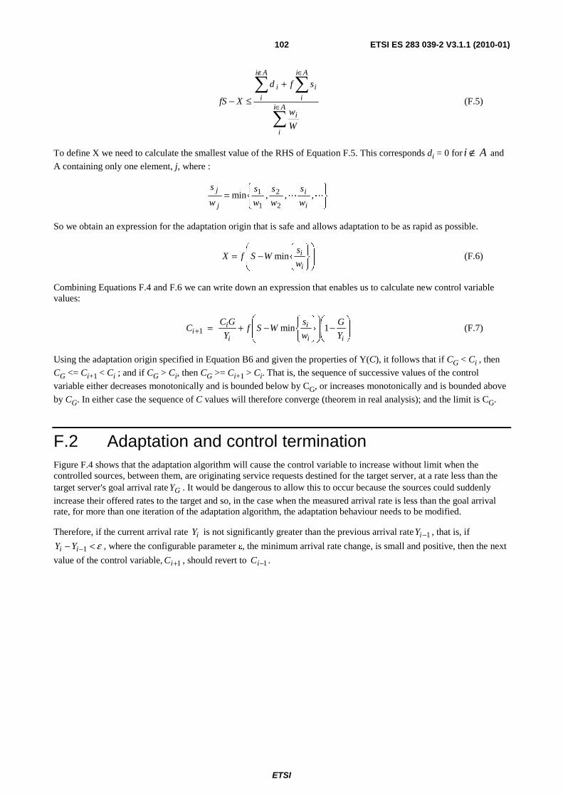
ETSI
ETSI ES 283 039-2 V3.1.1 (2010-01)102
∑
∑∑∈
∈∉+
≤−Ai
i
i
Ai
i
i
Ai
i
i
W
w
sfd
XfS (F.5)
To define X we need to calculate the smallest value of the RHS of Equation F.5. This corresponds di = 0 for Ai ∉ and
A containing only one element, j, where :
⎭⎬⎫
⎩⎨⎧
= LL ,,,min2
2
1
1
i
i
j
j
w
s
w
s
w
s
w
s
So we obtain an expression for the adaptation origin that is safe and allows adaptation to be as rapid as possible.
⎟⎟
⎠
⎞
⎜⎜
⎝
⎛
⎭⎬⎫
⎩⎨⎧
−=i
i
w
sWSfX min (F.6)
Combining Equations F.4 and F.6 we can write down an expression that enables us to calculate new control variable values:
⎟⎟⎠
⎞⎜⎜⎝
⎛−
⎟⎟
⎠
⎞
⎜⎜
⎝
⎛
⎭⎬⎫
⎩⎨⎧
−+=+ii
i
i
ii Y
G
w
sWSf
Y
GC C 1min1 (F.7)
Using the adaptation origin specified in Equation B6 and given the properties of Y(C), it follows that if CG < Ci , then
CG <= Ci+1 < Ci ; and if CG > Ci, then CG >= Ci+1 > Ci. That is, the sequence of successive values of the control
variable either decreases monotonically and is bounded below by CG, or increases monotonically and is bounded above
by CG. In either case the sequence of C values will therefore converge (theorem in real analysis); and the limit is CG.
F.2 Adaptation and control termination Figure F.4 shows that the adaptation algorithm will cause the control variable to increase without limit when the controlled sources, between them, are originating service requests destined for the target server, at a rate less than the target server's goal arrival rate GY . It would be dangerous to allow this to occur because the sources could suddenly
increase their offered rates to the target and so, in the case when the measured arrival rate is less than the goal arrival rate, for more than one iteration of the adaptation algorithm, the adaptation behaviour needs to be modified.
Therefore, if the current arrival rate iY is not significantly greater than the previous arrival rate 1−iY , that is, if
ε <− −1ii YY , where the configurable parameter ε, the minimum arrival rate change, is small and positive, then the next
value of the control variable, 1+iC , should revert to 1−iC .

ETSI
ETSI ES 283 039-2 V3.1.1 (2010-01)103
Figure F.4: Adaptation when sources originate requests at a rate < goal arrival rate
F.3 Capacity Modification Factor The capacity modification parameter has been introduced to allow the adaptation algorithm to work even if the capacity of the system falls below the sum total of the static capacity allocations (SLAs) defined in the Control Distribution. From Equation F.1 we can see that if the control variable falls below S (= ∑si), there is a possibility that some restrictors will be updated with negative leak rates unless the capacity modification parameter, f, is reduced such that G ≥ fS. The capacity modification parameter is set by the Control Adaptor in response to update_origin signals from the Control Distribution.
The Control Adaptor is configured with a parameter called the effective origin scalar, a, which is used to set f and thus control the ratio G/fS. The capacity modification parameter is calculated using:
⎟⎠
⎞⎜⎝
⎛=S
aGf ,1min (F.8)
where a is constrained to be less than or equal to 1.
The value of a is chosen to prevent the adaptation becoming locked when, due to some internal failure or configuration error, G < S. If a is 1, then there is a possibility of the adaptation becoming very slow, or even stalling due to the fact that the control variable can get very close to the adaptation origin. Setting a < 1, forces fS < G and therefore the adaptation origin (which is always ≤ fS) to move further away from G.
So when designing policies for setting the wi and si parameters, ensuring that S is significantly less that the nominal
system capacity and that a is set to ensure that is still the case even when there is some loss of processing capacity, will improve the adaptation of the control.

ETSI
ETSI ES 283 039-2 V3.1.1 (2010-01)104
Annex G (informative): Bibliography
• ETSI TR 182 015: "Telecommunications and Internet converged Services and Protocols for Advanced Networking (TISPAN); Next Generation Networks; Architecture for Control of Processing Overload".

ETSI
ETSI ES 283 039-2 V3.1.1 (2010-01)105
History
Document history
V3.1.0 November 2009 Membership Approval Procedure MV 20100110: 2009-11-11 to 2010-01-11
V3.1.1 January 2010 Publication