es 201 209-1 - v1.1.1 - identification card systems ... · european telecommunications standards...
TRANSCRIPT

European Telecommunications Standards Institute
ES 201 209-1 V1.1.1 (1997-07)ETSI Standard
Identification card systems;Telecommunications IC cards and terminals;
Interoperability with synchronous prepaid cards;Part 1: Requirements for off-line and on-line configurations

ES 201 209-1 V1.1.1 (1997-07)2
ReferenceDES/PTS-00209-1 (b7090icp.PDF)
KeywordsCard, payphone, interoperability, security
ETSI Secretariat
Postal addressF-06921 Sophia Antipolis Cedex - FRANCE
Office address650 Route des Lucioles - Sophia Antipolis
Valbonne - FRANCETel.: +33 4 92 94 42 00 Fax: +33 4 93 65 47 16
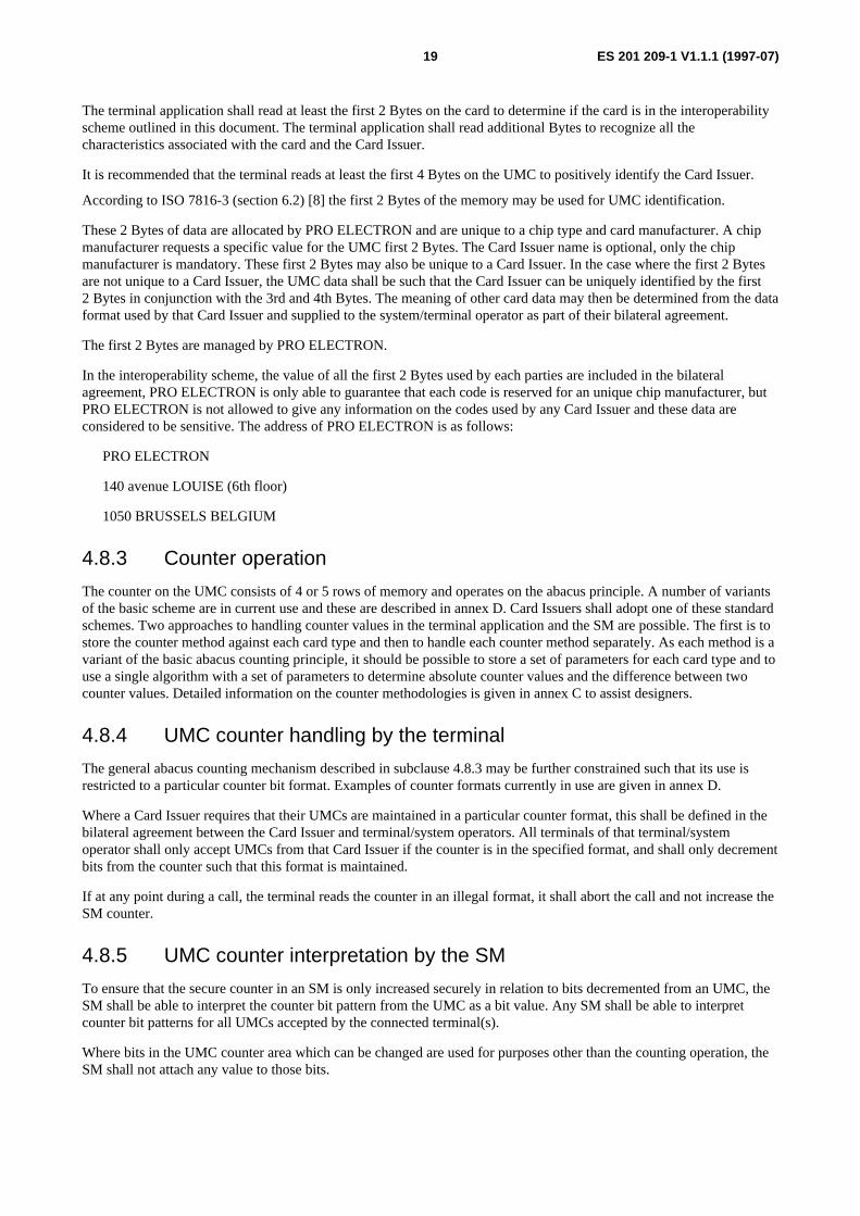
Siret N° 348 623 562 00017 - NAF 742 CAssociation à but non lucratif enregistrée à laSous-Préfecture de Grasse (06) N° 7803/88
X.400c= fr; a=atlas; p=etsi; s=secretariat
[email protected]://www.etsi.fr
Copyright Notification
No part may be reproduced except as authorized by written permission.The copyright and the foregoing restriction extend to reproduction in all media.
© European Telecommunications Standards Institute 1997.All rights reserved.

ES 201 209-1 V1.1.1 (1997-07)3
Contents
Intellectual Property Rights................................................................................................................................6
Foreword ............................................................................................................................................................6
1 Scope........................................................................................................................................................7
2 Normative references ...............................................................................................................................7
3 Definitions, symbols and abbreviations...................................................................................................83.1 Definitions ......................................................................................................................................................... 83.2 Symbols ............................................................................................................................................................. 93.3 Abbreviations................................................................................................................................................... 10
4 System overview ....................................................................................................................................104.1 Introduction...................................................................................................................................................... 104.2 Roles involved ................................................................................................................................................. 104.3 The interface model ......................................................................................................................................... 124.4 Security architecture ........................................................................................................................................ 134.5 The Security Module (SM) life cycle process model....................................................................................... 144.6 The key management process model................................................................................................................ 154.6.1 Overview.................................................................................................................................................... 154.6.2 The key management implementation model ............................................................................................. 154.6.3 Definitions of the keys................................................................................................................................ 164.7 The billing and accounting process model....................................................................................................... 174.8 User Memory Card (UMC) characteristics ...................................................................................................... 184.8.1 General characteristics ............................................................................................................................... 184.8.2 UMC recognition ....................................................................................................................................... 184.8.3 Counter operation....................................................................................................................................... 194.8.4 UMC counter handling by the terminal ...................................................................................................... 194.8.5 UMC counter interpretation by the SM...................................................................................................... 19
5 Procedures..............................................................................................................................................205.1 Introduction...................................................................................................................................................... 205.2 Key handling for interoperability (symmetric key scheme) ............................................................................. 205.2.1 Key management procedures of the Trusted Third Party (TTP) ................................................................205.2.2 Encryption of keys in the card management system................................................................................... 225.2.3 Handover of keys to the Operators' Management System .......................................................................... 235.2.4 Key download procedures.......................................................................................................................... 235.2.4.1 Initial key download ............................................................................................................................. 235.2.4.2 Updating of keys................................................................................................................................... 255.2.5 Adding a new application........................................................................................................................... 265.2.6 Removing an application............................................................................................................................ 275.3 Normal operation of the terminal and UMC handling ..................................................................................... 275.3.1 Preparatory steps (e.g. identify UMC type)................................................................................................ 285.3.2 Blacklist ..................................................................................................................................................... 285.3.3 Key diversification ..................................................................................................................................... 295.3.4 Card authentication .................................................................................................................................... 295.3.5 Decrease UMC counter .............................................................................................................................. 305.3.6 Increase SM counter................................................................................................................................... 325.3.7 Extract counter from the SM...................................................................................................................... 335.4 Payment and settlement.................................................................................................................................... 335.5 Operational differences for network based SM................................................................................................ 34
6 Data elements.........................................................................................................................................356.1 Data description technique............................................................................................................................... 356.2 System operator/Card Issuer interface (Interface 4)......................................................................................... 356.3 Operator's Management System (OMS)/terminal application interface (Interface 3) ...................................... 386.4 Terminal/UMC interface (Interface 2) ............................................................................................................. 406.5 Data elements to be held in the UMC .............................................................................................................. 41

ES 201 209-1 V1.1.1 (1997-07)4
6.6 Terminal/SM interface (Interface 1) ................................................................................................................ 426.6.1 Preparation and selection ........................................................................................................................... 426.6.2 UMC authentication ................................................................................................................................... 426.6.3 Counter increase......................................................................................................................................... 436.7 Data elements to be held in the SM ................................................................................................................. 436.8 SM/system interface (Interface 1 or A)............................................................................................................ 466.8.1 Counter extraction with a MAC ................................................................................................................. 466.8.2 Download a key.......................................................................................................................................... 47
7 Compliance with the terms of this document.........................................................................................48
Annex A (normative): Security requirements...................................................................................50
A.1 General ...................................................................................................................................................50
A.2 Security requirements on the TTP .........................................................................................................50
A.3 Basic security requirements ...................................................................................................................51
Annex B (normative): Key transfer procedures ...............................................................................52
B.1 The procedure for key transfer using a secure device............................................................................52
B.2 The procedure for key transfer using public key mechanisms...............................................................53B.2.1 Principles ......................................................................................................................................................... 53B.2.2 Public key initialization ................................................................................................................................... 54B.2.3 Certificates initialization.................................................................................................................................. 54B.2.3.1 A certificate computation ........................................................................................................................... 54B.2.3.2 B certificate computation ........................................................................................................................... 54B.2.4 Key initialization.............................................................................................................................................. 55B.2.4.1 A operations ............................................................................................................................................... 55B.2.4.2 B operations ............................................................................................................................................... 55
Annex C (normative): UMC counter methodologies ........................................................................57
C.1 Introduction............................................................................................................................................57
C.2 Size and location of the counter.............................................................................................................57C.2.1 Electrical value ................................................................................................................................................ 58C.2.2 Counter orientation .......................................................................................................................................... 58C.2.3 Special bits....................................................................................................................................................... 59C.2.4 Higher abacus stages........................................................................................................................................ 59C.2.5 Lower abacus stage.......................................................................................................................................... 59

ES 201 209-1 V1.1.1 (1997-07)5
Annex D (normative): Methods of operation for the counter on the UMC....................................61
D.1 Introduction............................................................................................................................................61
D.2 Method A ...............................................................................................................................................61
D.3 Method B................................................................................................................................................62
D.4 Method C................................................................................................................................................63
D.5 Method D ...............................................................................................................................................64
D.6 Method E................................................................................................................................................65
Annex E (informative): Recommendations on items subject to bilateral agreement betweenCard Issuers and terminal/system operators..............................................66
E.1 Introduction............................................................................................................................................66
E.2 Commercial matters ...............................................................................................................................66
E.3 Technical matters ...................................................................................................................................66
E.4 Security matters......................................................................................................................................67
Annex F (informative): Fixed Number Dialling (FND)......................................................................68
Annex G (informative): Additional data elements ..............................................................................70
G.1 System operator/Card Issuer interface ...................................................................................................70
Annex H (informative): MAC generation: an example.......................................................................72
H.1 Introduction............................................................................................................................................72
H.2 Detailed description of the data .............................................................................................................72
H.3 Detailed description of the algorithm ....................................................................................................73
Annex J (informative): Bibliography...................................................................................................74
J.1 Introduction............................................................................................................................................74
J.2 Informative references ...........................................................................................................................74
History ..............................................................................................................................................................75

ES 201 209-1 V1.1.1 (1997-07)6
Intellectual Property RightsETSI has not been informed of the existence of any Intellectual Property Right (IPR) which could be, or could becomeessential to the present document. However, pursuant to the ETSI Interim IPR Policy, no investigation, including IPRsearches, has been carried out. No guarantee can be given as to the existence of any IPRs which are, or may be, or maybecome, essential to the present document.
ForewordThis ETSI Standard (ES) has been produced by ETSI Project (EP) Pay Terminals and Systems (PTS).
The present document is part 1 of a multi-part document covering Identification card systems; Telecommunications ICcards and terminals; Interoperability with synchronous prepaid cards, as identified below:
Part 1: "Requirements for off-line and on-line configurations";
Part 2: "Security requirements".
ES 201 209-1 V1.1.1 (1997-07)7
1 ScopeThe purpose of this document is to securely:
- enable system operators to accept a User Memory Card (UMC) for payment purpose;
- enable system operators to claim money for proven UMC usage from Card Issuers;
- enable system operators as well as UMC and Security Module (SM) issuers to deal with key management issues.
In order to achieve this, the document describes:
- models containing assumptions about roles of involved parties;
- security architecture;
- the minimum functionality required by an application to handle the UMC-SM interfaces;
- methods of recognition of UMCs;
- the minimum data elements required at the SM interface;
- the SM interface required to handle UMC;
- SM interfaces to handle system requirements to provide secure information exchange between system operatorand Card Issuer;
- the interface to the management system that enables the secure exchange of relevant information (includingaccounting and billing) between the system operators and the Card Issuers.
This document is based on the assumption that the SM is an ICC and that the card architecture is based on EN 726-7 [2].Other implementations of the SM need to fulfil the functional requirements of this document to ensure interoperability ofUMCs. The Security Module (SM) may be based on the functions specified in EN 726-7 [2].
Details of these other implementations are outside the scope of this document.
2 Normative referencesReferences may be made to:
a) specific versions of publications (identified by date of publication, edition number, version number, etc.), inwhich case, subsequent revisions to the referenced document do not apply; or
b) all versions up to and including the identified version (identified by "up to and including" before the versionidentity); or
c) all versions subsequent to and including the identified version (identified by "onwards" following the versionidentity); or
d) publications without mention of a specific version, in which case the latest version applies.
A non-specific reference to an ETS shall also be taken to refer to later versions published as an EN with the samenumber.
[1] EN 726-3 (1994): "Identification Card Systems - Telecommunication Integrated Circuit Cards andTerminals - Part 3: Application independent card requirements".
[2] prEN 726-7: "Identification Card Systems - Telecommunication Integrated Circuit Cards andTerminals - Part 7: Security Module".
[3] ETR 115 (1994): "Terminal Equipment (TE); General concerns for the parties involved during thetelecommunication integrated circuit card life-cycle".
ES 201 209-1 V1.1.1 (1997-07)8
[4] ETR 165 (1995): "Human Factors (HF); Recommendation for a tactile identifier on machinereadable cards for telecommunications terminals".
[5] ISO 4127: "Codes for the representation of currencies and funds".
[6] ISO/IEC 7816-1 (1987): "Identification cards - Integrated circuit(s) cards with contacts - Part 1:Physical characteristics".
[7] ISO/IEC 7816-2 (1988): "Identification cards - Integrated circuit(s) cards with contacts - Part 2:Contact locations and minimum size".
[8] ISO/IEC 7816-3 (1990) and Amendments 1 & 2: "Identification cards - Integrated circuit(s) cardswith contacts - Part 3: Electronic signals and transmission protocols".
[9] ISO/IEC 7816-4 (1995): "Identification cards - Integrated circuit(s) cards with contacts - Part 4:Inter industry commands for interchange".
[10] ISO/IEC 7816-5 (1994): "Identification cards - Integrated circuit(s) cards with contacts - Part 5:Registration system for applications in IC cards".
[11] ISO/IEC 7816-6: "Identification cards - Integrated circuit(s) cards with contacts - Part 6: Inter-industry data elements".
[12] ISO 10202-1: "Financial transaction cards - Security architectures of financial transaction systemsusing Integrated Circuit Cards - Part 1: Card life cycle".
[13] ISO/IEC CD 11770-3 (1996): "Key Management - Part 3: Mechanisms using asymmetrictechniques".
[14] ITU-T Recommendation X.680 | ISO/IEC 8824-1 (1994): "Information technology - Open SystemsInterconnection - Abstract Syntax Notation One (ASN.1): Specification of basic notation".
[15] ITU-T Recommendation X.682 | ISO/IEC 8824-3 (1994): "Information technology - Open SystemsInterconnection - Abstract Syntax Notation One (ASN.1): Constraint specification".
[16] ITU-T Recommendation X.690 | ISO/IEC 8825-1 (1994): "Information technology - Open SystemsInterconnection - ASN.1 encoding rules: Specification of Basic Encoding Rules (BER), CanonicalEncoding Rules (CER) and Distinguished Encoding Rules (DER)".
[17] ITU-T Recommendation X.691 | ISO/IEC 8825-2 (1994): "Information technology - Open SystemsInterconnection - ASN.1 encoding rules: Specification of Packed Encoding Rules (PER)".
[18] ITSEC: "Information Technology Security Evaluation Criteria (ITSEC), Provisional HarmonisedCriteria", Version 1.2, June 1991 (ISBN 92-826-3004-8).
[19] ITU-T Recommendation E.164 (1991): "Numbering plan for the ISDN era".
3 Definitions, symbols and abbreviations
3.1 DefinitionsFor the purposes of the present document, the following definitions apply:
Card Issuer: The party that is responsible for the data on an UMC (including the secret key), and ultimately receivesthe payment for units when an UMC is purchased.
card management system: A system belonging to a Card Issuer which is used to maintain records which may includedata related to UMCs issued by that party and payment claimed by the system operators. Data such as managementinformation and secure details of revenue taken from UMCs may be exchanged with one, or more, Operators'Management Systems.
key: A sequence of symbols that controls the operations of encipherment and decipherment.
ES 201 209-1 V1.1.1 (1997-07)9
key management: The generation, storage, distribution, deletion, archiving and application of keys in accordance witha security policy.
Operator's Management System (OMS): A system belonging to a system operator which communicates with anumber of terminals to distribute management information and collect data, such as secure details of revenue obtainedfrom UMCs.
off-line: A terminal, or a terminal plus connecting unit (including Security Module functionality), can handle anapplication stand-alone during a transaction. From time to time however, an information exchange will take place withthe system.
on-line: A connection to the system is needed during each transaction.
pre-payment: A payment method using an IC card, where the card contains a pre-payment application. The pre-paidvalue is stored in the card and offers access to one, or more, applications. Pre-paid value means that payment is receivedin advance.
Secure Device (SD): A device to store the key KTTP pre-loaded by the Trusted Third Party (TTP) and to encryptloading keys Kload. During operation a loading key can also be stored and further keys can be encrypted. With the securedevice different key formats can be adopted.
Security Module (SM): A device containing logically and physically protected secrets - algorithm(s), related key(s),security procedures and information to protect applications in such a way that unauthorized access is not feasible. Inorder to achieve this the module may in addition be further physically, electrically and logically protected (as inEN 726-7 [2]).
system operator: An organization that operates a telecommunications system which accepts payment for access to itsservices by means of UMCs issued by Card Issuer(s).
telecommunication unit: A telecommunication unit represents a certain amount of service from a specified serviceprovider.
NOTE: A telecommunication unit may represent monetary unit(s) but also a charge pulse of e.g. the telephonenetwork.
terminal operator: An organization that operates terminals which accept payment for access to their services by meansof UMCs issued by Card Issuer(s).
terminal: A device which provides a user with access to the telecommunications system of a system operator, acceptingpayment by means of UMCs issued by a Card Issuer.
Trusted Third Party (TTP): A security authority, or its agent, trusted by other entities with respect to security relatedactivities. In particular, a TTP is trusted for the purposes of key management.
User Memory Card (UMC): The UMC is a memory card with a synchronous protocol and cryptographic security. Theuser pays the Card Issuer for units which may subsequently be used for access to a service from a terminal or systemoperator. It is hence a pre-payment card. It has at least mechanisms for:
- one way authentication of the UMCs identity (internal authentication);
- handling of a signed counter value, i.e. the counter value is included in the authentication;
- allowing only a decrease in the value of the counter.
An UMC is called a memory card because it is a type of ICC that contains read/write non-volatile memory and hardwired logic but no microprocessor. ISO 7816 [6 to 11] specifies asynchronous ICCs. Only certain aspects apply toUMCs that use a synchronous protocol.
3.2 SymbolsFor the purposes of the present document, the following symbols apply:
. . . In ITU-T Recommendation X.680 [14] data descriptions ellipsis indicate that extra data elementscould be added in the future at that point in the data type.
ES 201 209-1 V1.1.1 (1997-07)10
3.3 AbbreviationsFor the purposes of the present document, the following abbreviations apply:
ASN.1 Abstract Syntax Notation number OneBCD Binary Coded Decimal (a scheme for using 4 bits to encode 1 decimal digit)CHV Card Holder VerificationCI Card IssuerDF Dedicated FileEEPROM Electrically Erasable and Programmable ROMEF Elementary FileFND Fixed Number DiallingIC Integrated CircuitICC IC CardIIN Issuer Identification NumberITSEC Information Technology Security Evaluation CriteriaKTTP Key TTPKMttp Master Key ttpMAC Message Authentication CodeOMS Operator's Management SystemPIN Personal Identification NumberROM Read-Only MemorySD Secure DeviceSM Security ModuleTLC Transport Locking Codettp trusted third partyTTP Trusted Third Partyumc user memory cardUMC User Memory CardVpp programming voltage
4 System overview
4.1 IntroductionThis document describes the role of various parties and system components. Not all of the requirements in this documentare relevant to all parties, or system components.
Conformance testing is outside the scope of this document.
In this clause an overview of the document is given. It describes the scenario of accepting User Memory Cards ofdifferent Card Issuers (CI) at terminals of different operators. It starts with a description of the parties involved in theprocess.
4.2 Roles involvedIn the System the following five main roles are involved:
- system operator;
- Card Issuer;
- SM manufacturer;
- user;
- Trusted Third Party (TTP).
In certain cases a single party may undertake several of these roles.

ES 201 209-1 V1.1.1 (1997-07)11
In the following, a short description of each of these roles is given:
System Operator:
The system operator gives service, accepts UMCs as the payment mechanism at a terminal, uses and manages SecurityModules and a (background) system connected to the terminals and Security Modules, for the purpose of securelyclaiming payment from Card Issuers.
These 3 roles of giving service, managing Security Modules, and claiming money from Card Issuers (and othernecessary management functions) may be all performed by a single entity or may be split between commercial entities.An entity that performs the first two roles only and relies on some other entity for the (background) system that cansecurely claim payment from Card Issuers is referred to in this document as a Terminal Operator.
Card Issuer:
The Card Issuer is the party issuing the UMC. The Card Issuer generates and owns the secret keys, which are needed forthe operation of the UMCs. The Card Issuer receives the funds, with which the services delivered via the terminal needto be paid. The Card Issuer receives from the system operator the proof that a certain number of units have beendecreased at terminals of the system operator from UMCs issued by the Card Issuer.
SM Manufacturer:
The SM manufacturer loads certain parts of the application into the Security Module. The SM manufacturer isresponsible for demonstrating that the SM fulfils specified security requirements. This may be achieved via a securityevaluation (such as an ITSEC evaluation and/or a reverse engineering evaluation).
User:
The User pays for the UMC and is then the owner of the UMC. They use the UMC to pay for the services they can get atthe terminal.
NOTE 1: When the user has paid for the UMC, the Card Issuer may have no rights over the UMC at all and the usermay be the owner. Alternatively the Card Issuer may retain rights to the UMC itself, and the user onlyhave the right to use the value on the card.
Trusted Third Party (TTP):
The task of the TTP is to initialize a mechanism, which allows keys to be downloaded from a Card Issuer into theSecurity Module of a system operator without either party getting to know the keys in plain text form. To do so, the TTPloads an initial loading key into the Security Modules. To enable the Card Issuer to encrypt the keys without knowledgeof the initial loading key, the same initial loading key can be installed into some other security device. Thus the CardIssuer can encrypt his operational keys with this secure device and send the encrypted keys to the system operator.
After download into the Security Modules by the system operator, they are decrypted within the Security Modules.
NOTE 2: For economical and practical reasons, the role of the TTP might be fulfilled by the Security Modulemanufacturer, because the Security Module manufacturer has to guarantee somehow that correctmechanisms (software and hardware) are implemented in the Security Module, and has physical access tothe Security Module in the initial phase.
The tasks of a TTP include the following:
- Optionally generate the data field "Master Key (KMttp)" in a secure environment;
- Generate (or optionally diversify from a master key) a Terminal Operator specific data field "KTTP";
- Install the data field "KTTP" in a Secure Device, or use another secure transfer mechanism;
- Install the data field "KTTP" in the Security Modules of the Terminal Operator;
- Protect the TESA-7 algorithms physically.
ES 201 209-1 V1.1.1 (1997-07)12
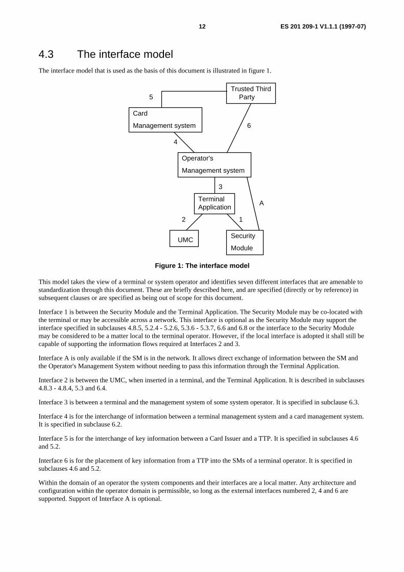
4.3 The interface modelThe interface model that is used as the basis of this document is illustrated in figure 1.
Trusted ThirdParty
Card
Management system
Operator's
Management system
TerminalApplication
UMCSecurity
Module
12
3
4
5
6
A
Figure 1: The interface model
This model takes the view of a terminal or system operator and identifies seven different interfaces that are amenable tostandardization through this document. These are briefly described here, and are specified (directly or by reference) insubsequent clauses or are specified as being out of scope for this document.
Interface 1 is between the Security Module and the Terminal Application. The Security Module may be co-located withthe terminal or may be accessible across a network. This interface is optional as the Security Module may support theinterface specified in subclauses 4.8.5, 5.2.4 - 5.2.6, 5.3.6 - 5.3.7, 6.6 and 6.8 or the interface to the Security Modulemay be considered to be a matter local to the terminal operator. However, if the local interface is adopted it shall still becapable of supporting the information flows required at Interfaces 2 and 3.
Interface A is only available if the SM is in the network. It allows direct exchange of information between the SM andthe Operator's Management System without needing to pass this information through the Terminal Application.
Interface 2 is between the UMC, when inserted in a terminal, and the Terminal Application. It is described in subclauses4.8.3 - 4.8.4, 5.3 and 6.4.
Interface 3 is between a terminal and the management system of some system operator. It is specified in subclause 6.3.
Interface 4 is for the interchange of information between a terminal management system and a card management system.It is specified in subclause 6.2.
Interface 5 is for the interchange of key information between a Card Issuer and a TTP. It is specified in subclauses 4.6and 5.2.
Interface 6 is for the placement of key information from a TTP into the SMs of a terminal operator. It is specified insubclauses 4.6 and 5.2.
Within the domain of an operator the system components and their interfaces are a local matter. Any architecture andconfiguration within the operator domain is permissible, so long as the external interfaces numbered 2, 4 and 6 aresupported. Support of Interface A is optional.

ES 201 209-1 V1.1.1 (1997-07)13
4.4 Security architectureThe interfaces which are particularly relevant to the security architecture are highlighted in figure 2.
Trusted ThirdParty
Card
Management system
Operator's
Management system
TerminalApplication
UMCSecurity
Module
12
3
4
5
6
A
Figure 2: The security related aspects of the interface model
The security architecture takes into account the fact that the SM and the UMC can be regarded as being secure, but theterminal application is not regarded as secure. The SM checks that the UMC is authentic. However, the terminalapplication does act as the master. That is, it issues commands to the UMC and the SM. The UMC and SM can neverinitiate commands, only make responses to terminal application commands. This situation is illustrated in figure 3. TheSM (and potentially also the UMC) can check the sequence of commands, as well as their content, and respondappropriately if the content or command sequence does not obey set rules. The terminal operator and/or Card Issuer maystill require to be assured that the terminal application conforms to its specification and operates correctly under allcircumstances. In particular, they need to be assured that UMCs from Card Issuers with which the terminal operator hasagreements are correctly handled.
UMC
Terminal Application
Security
Module(SM)
Master (lower security)
Slave (highly secure) Slave (supposed securewhen authenticated)
Figure 3: The security architecture model for card authentication
ES 201 209-1 V1.1.1 (1997-07)14
A functional model of the security architecture is given. There are different phases to be distinguished. In aninitialization phase physical components of the system such as:
- Security Module;
- secure device (if used);
- UMC,
are exchanged between different parties. The UMC is given to the Users by the Card Issuer. The Security Module isgiven to the TTP by the Security Module manufacturer. The TTP passes it to the system operator after having installedthe initial loading key. The security device is given to the TTP, which installs also in the secure device the initial loadingkey. Afterwards it is passed to the Card Issuer.
In the operational phase there are several different actions to be considered:
- key download;
- use of UMC (including authentication and decrementing);
- counter increase of SM counter;
- counter extraction of SM counter.
Key download and counter extraction are mainly important for the interface between the system operator and the CardIssuer, but they are also important for the interface between the Security Module and system of the system operator.Counter increase and the use of the UMC are related to the interface between the UMC and the Security Module, whichis indirect via the terminal.
It is recommended that all data are classified into "not security sensitive", "security sensitive" and "highly securitysensitive" and then to decide which data should be secured by additional means (integrity checksum, encryption) duringa data transfer.
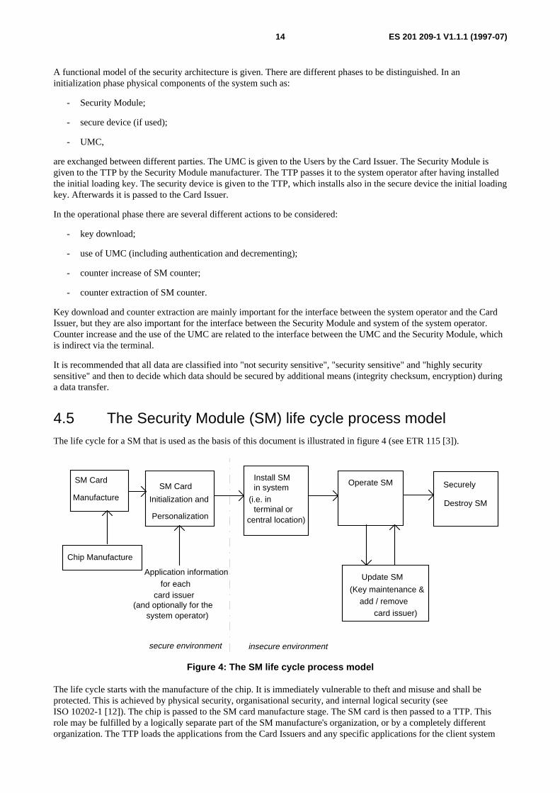
4.5 The Security Module (SM) life cycle process modelThe life cycle for a SM that is used as the basis of this document is illustrated in figure 4 (see ETR 115 [3]).
SM Card
Chip Manufacture
SM Card
Initialization and
Install SMin system
(i.e. in
Operate SM
Application informationfor each
card issuer
central location)
Destroy SMterminal or
Manufacture
Update SM
Securely
(and optionally for thesystem operator)
(Key maintenance &add / remove
card issuer)
secure environment insecure environment
Personalization
Figure 4: The SM life cycle process model
The life cycle starts with the manufacture of the chip. It is immediately vulnerable to theft and misuse and shall beprotected. This is achieved by physical security, organisational security, and internal logical security (seeISO 10202-1 [12]). The chip is passed to the SM card manufacture stage. The SM card is then passed to a TTP. Thisrole may be fulfilled by a logically separate part of the SM manufacture's organization, or by a completely differentorganization. The TTP loads the applications from the Card Issuers and any specific applications for the client system
ES 201 209-1 V1.1.1 (1997-07)15
operator (as specified by that operator), the required cryptographic algorithm code and a secret key. This stage is knownas "personalization".
In practice, personalization may occur in two phases. The first phase involves the loading of the secure operating systemand the formation of an empty file structure. The second phase then involves the loading of the initial Card Issuerspecific data.
The personalized SM is handed over to the client system operator for installation in the terminal network and the SMenters the operational phase of its life. During this phase it will generally be necessary to load new keys, delete old keys,load, modify and delete data in dedicated and elementary files. Finally the SM shall be securely destroyed at the end ofits working life.
4.6 The key management process model
4.6.1 Overview
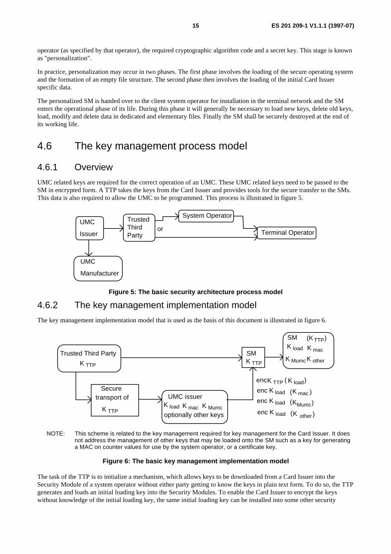
UMC related keys are required for the correct operation of an UMC. These UMC related keys need to be passed to theSM in encrypted form. A TTP takes the keys from the Card Issuer and provides tools for the secure transfer to the SMs.This data is also required to allow the UMC to be programmed. This process is illustrated in figure 5.
UMC
Issuer
TrustedThirdParty
System Operator
Terminal Operatoror
UMC
Manufacturer
Figure 5: The basic security architecture process model
4.6.2 The key management implementation model
The key management implementation model that is used as the basis of this document is illustrated in figure 6.
Trusted Third Party
K TTP
SM
Secure
K TTP
K TTP
UMC issuerK load K mac K Mumc
encK TTP K load( )
enc K load ( )K mac
enc K load ( )KMumc
SMK load
K Mumc
(K TTP)
transport of
optionally other keys enc K load ( )K other
K mac
K other
NOTE: This scheme is related to the key management required for key management for the Card Issuer. It doesnot address the management of other keys that may be loaded onto the SM such as a key for generatinga MAC on counter values for use by the system operator, or a certificate key.
Figure 6: The basic key management implementation model
The task of the TTP is to initialize a mechanism, which allows keys to be downloaded from a Card Issuer into theSecurity Module of a system operator without either party getting to know the keys in plain text form. To do so, the TTPgenerates and loads an initial loading key into the Security Modules. To enable the Card Issuer to encrypt the keyswithout knowledge of the initial loading key, the same initial loading key can be installed into some other security
ES 201 209-1 V1.1.1 (1997-07)16
device. Thus the Card Issuer can encrypt his operational keys with this secure device and send the encrypted keys to thesystem operator.
After download into the Security Modules by the system operator, they are decrypted within the Security Modules.
4.6.3 Definitions of the keys
The main keys required for the operation of this architecture are described below. Additional keys may be required forany particular implementation.
Counter MAC Key (K MAC )
For the secure readout of counters a key is necessary to create a signature on the value of the counter. This key KMACwill be specific for each Card Issuer, and shall not be known to the System Operator. Each Card Issuer will have at anytime one KMAC installed in a specific Security Module. At any time this KMAC can be replaced by a new version.
Initial Loading Key (K TTP)
To enable the download of keys into a Security Module managed by a non-trusted party, a special construct is necessarybetween Card Issuer, System Operator, and a TTP. This construct can be featured by a Secure Device containing theinitial loading key KTTP The key KTTP is generated by a TTP specific for every Card Issuer. It might either be derivedout of a master key in a secure way or specifically be chosen for every instance of the key. It is handed over to the CardIssuers.
The Card Issuer can encrypt the loading keys using the initial loading key KTTP. These encrypted keys can bedownloaded by the System Operator to the Security Module, which decrypts the key and install it in the proper locationwithout the System Operator being able to read this key.
The KTTP should never be known to any party but the TTP.
The KTTP shall be specific for each combination of System Operator and TTP, i.e. this TTP will determine this KTTP foreach System Operator ordering Security Modules from this TTP.
If a secure device is used, the Secure Device is handed over by the TTP to the Card Issuer directly, i.e. the SystemOperator will not be an intermediate partner in this process. The System Operator will however order the Secure Devicefrom a Security Module manufacturer and will have it delivered to the Card Issuer. The secure device encrypts the CardIssuer's keys. This document does not address how these encrypted keys are entered into the SM.
Master Initial Loading Key (K Mttp )
This is an optional key that may be used for two purposes:
a) As a master key for generating Card Issuer specific Initial Loading Keys (KTTP) via a key diversificationalgorithm. The same algorithm needs to be in the SM.
b) As a management key for the secure creation of file sets for additional Card Issuers.
SM Key Loading Key (Kload)
For the secure download of keys a key is necessary to encrypt the key to be installed into the Security Module. Apartfrom this encryption mechanism, a mechanism is necessary to insure the integrity of the keys, e.g. the use of a MessageAuthentication Code (MAC). This key Kload is again specific for each Card Issuer, and shall again not be known to theSystem Operator. Each Card Issuer will have at any time exactly one Kload installed in a single Security Module. At anytime this Kload can be replaced by a new version.
UMC Authentication Key (K umc)
The UMC Authentication Key (Kumc) is unique to each UMC. It is generated from an UMC authentication Master Key(KMumc) and the UMC's identification data by means of a key diversification algorithm. It is placed on the UMC by theCard Issuer, and is used internally within the UMC when the UMC is authenticated by a terminal, and when it is used topay for a transaction. It is very important that this key remains hidden inside the UMC and that it is not possible to readit out.

ES 201 209-1 V1.1.1 (1997-07)17
UMC Authentication Master Key (K Mumc)
The Card Issuer generates an UMC authentication Master Key (KMumc). It use this with a key diversification algorithmand card identification data to generate a separate authentication key (Kumc) for each UMC it issues. The Card Issueralso transfers this UMC authentication Master Key (KMumc) in encrypted form to the Security Modules that will be usedfor authenticating UMC transactions. This document specifies the use of TTP for this transfer as an aid to maintainingoverall security. The actual secure physical transfer of this important key may be achieved using a secure device thatencrypts the key and keeps it hidden from the terminal operator or by any other means of secure (usually encrypted)transfer.
The Security Modules use the UMC authentication Master Key (KMumc) together with a key diversification algorithmand card identification data to independently generate authentication key (Kumc) for an UMC it is requested toauthenticate. It uses this key in the UMC authentication algorithm.
It is recommended that at least 3 versions of KMumc are supported.
NOTE: Some systems require the support of 4, or more, versions of KMumc.
UMC Certification Master Key ( KMcer) optional
The aim of the certificate is to increase the UMC security during its life cycle. The certificate is a 16-bit value which canbe written in the UMC at a specific place and at a specific time. For example it can be written just before the delivery ofthe card to the customer. Then in case of theft of the UMC before certificate inscription, the UMC is valueless.
The certificate can also be used to reload the UMC. In this case it proves that the UMC has been reloaded with trueunits.
The certificate is computed with UMC data and a secret key KMcer. The SM shall support at least 4 KMcer versions, ifthe certification process is supported.
The SM will check the certificate value during the authentication procedure. This operation is not mandatory.
The KMcer key is loaded using the same procedure as KMumc.
4.7 The billing and accounting process modelThe billing and accounting model that is used as the basis of this document is illustrated in figure 7.
User
Card Issuer System operator
ServiceMoney
Money
Signed bill
UMC"bits" decremented from UMC
Figure 7: The billing and accounting process model
The model shows an overview of the way the payment system works. The complete cycle consists of 3 steps:
1. The Card Issuer sells UMCs to the user i.e. they give the UMCs to the user and receive money for it.
2. The user receives service at a terminal of the system operator. The terminal application has to ensure that thecounter in the UMC is decreased by the correct amount over time as the service is used and that the counter in theSecurity Module is increased by the same amount.

ES 201 209-1 V1.1.1 (1997-07)18
3. The system operator presents the counters of the Security Module to the Card Issuer and receives money from theCard Issuer. This is represented in figure 7 as the "signed bill", which is just the counter value "signed" with aMAC.
4.8 User Memory Card (UMC) characteristics
4.8.1 General characteristics
This document considers an UMC to be a synchronous memory card with the following common features:
- Identification area;
- this area contains data needed to identify the chip type and the Card Issuer.
- Counter;
- the counter is an abacus counter. The counting area consists of several counter stages. Counting is done bywriting bits in the relevant counter stages. A counter backup procedure exists and can be used to inform theterminal that a problem occurred in the counter set up procedure.
- Authentication;
- to check the validity of the card a one way authentication mechanism is used. This mechanism is based on astrong authentication algorithm (cryptographic method not based on a PIN or CHV), using a secret key, achallenge and card authentication data including the counting area, the identification area and possibly otherdata.
- In accordance with ISO 7816-1 and ISO 7816-2 [6, 7] and 3 (section 1 to 4.2.7) [8].
The UMC has two different access configurations: Issuer configuration and User configuration. In Issuer configurationaccess is permitted to certain memory locations on presentation of the correct value for the "Transport Locking Code".Some ICC types do not have this "Transport Locking Code" facility and thus can be programmed without presenting acorrect value. Issuer configuration is intended to be used by IC manufacturers, and by ICC manufacturers in thepersonalization phase. Once the User configuration has been entered it shall not be possible to revert to Issuerconfiguration. In User configuration access shall be strictly controlled by security logic on the IC.
The overall physical dimensions of the UMC shall be in accordance with the ID-1 type as specified in ISO 7816-1 [6].The location, size and position of the electrical contacts shall be in accordance with ISO 7816-2 [7]. The surface profileof the electrical contacts shall conform to ISO 7816-1 [6].
The card may carry an indentation on one edge, or some other physical feature, which enables a person with impairedvision to insert the UMC into the terminal in the correct orientation (see ETR 165 [4]).
The UMC shall have electrical contacts as denoted in ISO 7816-2 [7]. The Vpp contact shall not be used.
4.8.2 UMC recognition
There are different low level protocols used by UMC chip manufacturers. Some UMC readers will only be able to useone of these protocols. Operators of such terminals will only be able to accept UMCs from Card Issuers using thatprotocol. If the reader can use more than one, then it has to recognize which one is implemented on any UMC presentedto it. The terminal shall try each protocol in turn until one yields readable data. If all available possibilities fail toproduce good data, then the terminal shall reject the UMC as unreadable. The reader shall not electrically damage theUMC nor modify the UMC counter during these operations.
It shall be possible for the terminal application to be able to recognize from the data on an UMC, which Card Issuerissued that UMC (so that the correct files in the MS can be selected for UMC authentication and counter increment).
ES 201 209-1 V1.1.1 (1997-07)19
The terminal application shall read at least the first 2 Bytes on the card to determine if the card is in the interoperabilityscheme outlined in this document. The terminal application shall read additional Bytes to recognize all thecharacteristics associated with the card and the Card Issuer.
It is recommended that the terminal reads at least the first 4 Bytes on the UMC to positively identify the Card Issuer.
According to ISO 7816-3 (section 6.2) [8] the first 2 Bytes of the memory may be used for UMC identification.
These 2 Bytes of data are allocated by PRO ELECTRON and are unique to a chip type and card manufacturer. A chipmanufacturer requests a specific value for the UMC first 2 Bytes. The Card Issuer name is optional, only the chipmanufacturer is mandatory. These first 2 Bytes may also be unique to a Card Issuer. In the case where the first 2 Bytesare not unique to a Card Issuer, the UMC data shall be such that the Card Issuer can be uniquely identified by the first2 Bytes in conjunction with the 3rd and 4th Bytes. The meaning of other card data may then be determined from the dataformat used by that Card Issuer and supplied to the system/terminal operator as part of their bilateral agreement.
The first 2 Bytes are managed by PRO ELECTRON.
In the interoperability scheme, the value of all the first 2 Bytes used by each parties are included in the bilateralagreement, PRO ELECTRON is only able to guarantee that each code is reserved for an unique chip manufacturer, butPRO ELECTRON is not allowed to give any information on the codes used by any Card Issuer and these data areconsidered to be sensitive. The address of PRO ELECTRON is as follows:
PRO ELECTRON
140 avenue LOUISE (6th floor)
1050 BRUSSELS BELGIUM
4.8.3 Counter operation
The counter on the UMC consists of 4 or 5 rows of memory and operates on the abacus principle. A number of variantsof the basic scheme are in current use and these are described in annex D. Card Issuers shall adopt one of these standardschemes. Two approaches to handling counter values in the terminal application and the SM are possible. The first is tostore the counter method against each card type and then to handle each counter method separately. As each method is avariant of the basic abacus counting principle, it should be possible to store a set of parameters for each card type and touse a single algorithm with a set of parameters to determine absolute counter values and the difference between twocounter values. Detailed information on the counter methodologies is given in annex C to assist designers.
4.8.4 UMC counter handling by the terminal
The general abacus counting mechanism described in subclause 4.8.3 may be further constrained such that its use isrestricted to a particular counter bit format. Examples of counter formats currently in use are given in annex D.
Where a Card Issuer requires that their UMCs are maintained in a particular counter format, this shall be defined in thebilateral agreement between the Card Issuer and terminal/system operators. All terminals of that terminal/systemoperator shall only accept UMCs from that Card Issuer if the counter is in the specified format, and shall only decrementbits from the counter such that this format is maintained.
If at any point during a call, the terminal reads the counter in an illegal format, it shall abort the call and not increase theSM counter.
4.8.5 UMC counter interpretation by the SM
To ensure that the secure counter in an SM is only increased securely in relation to bits decremented from an UMC, theSM shall be able to interpret the counter bit pattern from the UMC as a bit value. Any SM shall be able to interpretcounter bit patterns for all UMCs accepted by the connected terminal(s).
Where bits in the UMC counter area which can be changed are used for purposes other than the counting operation, theSM shall not attach any value to those bits.

ES 201 209-1 V1.1.1 (1997-07)20
Where a number of different counter bit formats are to be supported, the SM may optionally use a general countingmethod together with a set of parameters to modify it for the different abacus counter formats. Parameters may be usedfor the following purposes:
To indicate the value of a counting bit in each counter row.
To indicate how to identify an erased/written counter bit.
...
Other parameters may be used to further define the accepted counter formats and to control the minimum number ofauthentication signature bits required for secure counter increase.
If different counting methods or counter parameters are supported for one Card Issuer, the counter method or parametersused by the SM shall be securely linked to the KMumc selected.
5 Procedures
5.1 IntroductionAll procedures described in the following subclauses are based on the system overview described in clause 4.
In this subclause the following procedures are described:
- Key handling.
- Normal operation of the Terminal- and UMC-handling.
- Payment and settlement.
- Operational differences for network based Security Module (SM).
Each procedure uses several data elements. The structures of the data elements are described in clause 6.
There are 3 mandatory different kinds of keys for the Card Issuer to be downloaded into the system of the operator, loadkey, MAC key and UMC master key. Other keys may also be used for specific purposes. The purpose of the load key isto have an additional key hierarchy between the initial loading key of the TTP and the operational keys (MAC key andUMC master key). The MAC key serves as a key to sign the counter in the Security Module, where the counter isspecific for the Card Issuer. The UMC master key is the key that is diversified into individual keys for each Card Issuedby the Card Issuer.
The Card Issuer initiates the key management process when issuing new types of cards requiring new keys, or when one,or more, current keys have expired. The new keys shall be loaded in all the SM which accepts these UMCs.
5.2 Key handling for interoperability (symmetric key scheme)
5.2.1 Key management procedures of the Trusted Third Party (TTP)
It is required that the Trusted Third Party maintains a security management system to fulfil the security requirements.
The first step of the Trusted Third Party is to generate for each Card Management system a dedicated Initial LoadingKey (KTTP). That dedicated KTTP shall only be known to the TTP. That KTTP therefore needs to be stored in a verysecure way.

ES 201 209-1 V1.1.1 (1997-07)21
GenerateK ttp
K ttp (1)
SM of
Operator
install
K ttp (2)
K ttp (n)
handover tocard issuer 1e.g. with SD1
handover tocard issuer 2e.g. with SD2
handover tocard issuer ne.g. with SDn
or Kttp (n)
Interface 6
Interface 5
Figure 8a: TTP key generation - single key or randomly generated keys
GenerateK Mttp
K ttp 1
SM of
Operator
install
diversify
K ttp 2
K ttp n
handover tocard issuer 1e.g. with SD1
handover tocard issuer 2e.g. with SD2
handover tocard issuer ne.g. with SDn
Interface 6
Interface 5
Figure 8b: TTP key generation from a master key
There are 3 schemes for generating and handling KTTP. The first is to use the same value for KTTP for each Card Issuer.Only this one value needs to be loaded into the SM. The main disadvantage of this scheme is that if this single value ofKTTP is used for the whole of the SM life and it becomes known to anyone other than the TTP, then the complete systemis compromised. Therefore this scheme is not recommended. This scheme is illustrated in figure 8a.
NOTE: A viable variation on this scheme is to replace the current version of KTTP with Kload each time keys aredownloaded so that on each key download cycle KTTP is given a new value.
The second is for the TTP to choose an arbitrary value for KTTP for each Card Issuer. This scheme is illustrated infigure 8a. It implies that SMs have to be pre-loaded with the KTTP values for each Card Issuer. If an unanticipated CardIssuer enters the system then SMs from operators intending to interoperate with UMCs from that Card Issuer will have anew KTTP loaded under the control of the TTP.
The third scheme is illustrated in figure 8b. A master key (KMttp) is generated by the TTP. A Card Issuer identificationparameter and a diversification algorithm are used to generate separate values for KTTP for each Card Issuer. The singlemaster key (KMttp) value is loaded into each SM. Whenever a Card Issuer downloads new keys to an SM, it has togenerate the correct value of initial loading key, KTTP, for that Card Issuer by using the same diversification algorithm,Card Issuer identifier and master key (KMttp) value. This method is more secure than the first method. It is not as secureas the second method, but does not require the permanent storage of many KTTP values in the SM and the attendantupdate problems.
The generated KTTP (first and second scheme) or KMttp (third scheme) will be installed in the SMs of an Operatorduring a personalization process of the SMs. All SMs will then be handed over to the operator.

ES 201 209-1 V1.1.1 (1997-07)22
If that operator wants now to accept the cards of a Card Issuer n it is necessary to hand over the KTTP n to the Cardmanagement system to prepare the further steps (encryption of the keys of the Card management system, hand over tothe Operator's Management System and installation in the SMs of the operator).
5.2.2 Encryption of keys in the card management system
During a key exchange the following data elements need to be encrypted before they are handed over from a CardManagement System to an Operator's Management System:
- Kload;
- KMumc;
- KMAC;
- optionally KMcer.
The encryption of these keys of the Card Management system can be done by means of the secure device which ishanded over from a TTP and plugged in to the system or by a piece of software in the system.
The following tasks shall be performed:
- Generate new keys (e.g. Kload, and KMAC).
- Receive the data field Kload in a secure way. It is recommended that the Card Management uses a secure centralcomputer to handle the cryptographic data. This central computer shall be located in a secure area.
- The data field Kload is encrypted with the data field KTTP and the recommended algorithm agreed between thepartners in the required format.
- The encrypted Kload is then handed over again to the Card Management system.
- An encryption tool encrypts the KMumc, KMAC, and any other keys with the Kload.
- The data fields KMumc and KMAC are handed over in encrypted form.
After the initialization phase carried out by the TTP, the TTP hands over the Security Modules to the TerminalOperator. After that step the Security Modules are prepared to receive cryptographic data of the Card ManagementSystem.
It is recommended that TESA-7 is used as the key diversification and the key encryption algorithm.
After the encryption of the relevant keys the encrypted data needs to be handed over to the Terminal Operator in the dataelements described in clause 7.
If a secure device is used, then the procedure is given in annex B.1.
If a secure device is not used, then some other mechanism has to be agreed between the parties. Such alternativemechanisms are not specified in this document.
If a secure device is used, then the Card Management System provides an interface for the Secure Device.

ES 201 209-1 V1.1.1 (1997-07)23
5.2.3 Handover of keys to the Operators' Management System
During a key exchange the following data elements need to be handed over from a Card Management System to anOperator's Management System:
encKTTP (Kload);
encKload(KMumc);
encKload(KMAC);
optionally encKload(KMcer).
In addition to these encrypted keys, sufficient information has to be known by both parties to identify the use of the keys(e.g. key identification, format, and algorithm).
It is optional for Kload to replace KTTP and become the new "KTTP" for the next download of "Kload". This depends on
the method to be used for the subsequent update of Kload.
Trusted ThirdParty
Card
Management system
Operator's
Management system
TerminalApplication
UMCSecurity
Module
12
3
5
6
4
A
Figure 9: The key exchange model
During a key exchange between Card Issuer and terminal operator the highlighted boxes are relevant.
5.2.4 Key download procedures
5.2.4.1 Initial key download
After a secure hand over of the encrypted keys from a Card Management System to a Operator's Management Systemthe encrypted keys need to be downloaded into the Security Modules. These encrypted keys are then decrypted andinstalled in the Security Module.

ES 201 209-1 V1.1.1 (1997-07)24
Trusted ThirdParty
Card
Management system
Operator's
Management system
TerminalApplication
UMCSecurity
Module
12
3
5
6
4
A
Figure 10: The key download procedures model
During a key download procedure the highlighted boxes are relevant.
For a secure download of the encrypted data of a Card Management System into the Security Module the followingprocedures are necessary:
Download of the encrypted data fields into the Terminal Application in a secure way: it is strongly recommended that afurther cryptographic layer is used for a secure download of data fields.
If a Security Module structured according to EN 726-7 [2] is used then the procedure is as follows:
- The Terminal Application or Operator's Management System selects the DF of the SM.
- The data field "encKTTP(Kload)" is handed over to the SM.
- The SM decrypts the data field and installs the Kload in a special EF in the SM.
- The data field "encKload(KMumc)" is handed over to the SM, decrypted in the SM and installed.
- The data field "encKload(KMAC)" is handed over to the SM, decrypted in the SM and installed.
- Other keys if required (e.g. for certification).
It is optional for Kload to replace KTTP and become the new "KTTP" for the next download of "Kload". This depends onthe method to be used for the subsequent update of Kload.
The encryption mechanism shall also include a process to ensure the integrity of the key, e.g. the use of a MessageAuthentication Code (MAC). The integrity mechanism (e.g. MAC) shall be calculated from the key and optionallyadditional data (e.g. to securely link the data to the key).

ES 201 209-1 V1.1.1 (1997-07)25
5.2.4.2 Updating of keys
Trusted ThirdParty
Card
Management system
Operator's
Management system
TerminalApplication
5
4
6
3
UMCSecurity
Module
12
A
Figure 11: The key updating procedures model
During the update of the keys held in a Security Module, the highlighted boxes are relevant.
The following procedures relate to the update of any of the keys related to a specific Card Issuer in the Security Module.These procedures apply to the following keys, which originate from the Card Issuer:
- Kload;
- KMAC;
- KMumc;
- other keys, such as a certification key, KMcer, for checking certificates on the UMC.
In the case of any optional keys which originate from another source (e.g. an operator), the procedures below should bemodified as appropriate e.g. to use a TTP (and optionally a secure device).
All keys other than Kload are encrypted with Kload. For Kload there are two possibilities:
a) all versions of Kload are encrypted with the same KTTP;
b) a new version of Kload is encrypted using the previous version of Kload.
These procedures assume that initial key download has already been performed (as defined in subclause 5.2.4.1). In thisstate the Security Module application related to a Card Issuer has been initialized with a loading key Kload specific forthat Card Issuer.
The procedure for the updating of keys shall meet the following basic requirements.
1) The Card Issuer shall encrypt the new key using Kload (or KTTP for Kload). The encryption mechanism shallalso include a process to ensure the integrity of the key, e.g. the use of a Message Authentication Code (MAC).The integrity mechanism (e.g. MAC) shall be calculated from the key and optionally additional data (e.g. tosecurely link the data to the key).
2) The encrypted key data shall be handed over to the operator for transmission via the Operator's ManagementSystem to the Security Module. Additional data may also be necessary to the key updating process, such asidentification of the key to be replaced and a key version number.

ES 201 209-1 V1.1.1 (1997-07)26
3) The Security Module shall verify the integrity of the key (e.g. by checking the MAC for that key or a sufficientredundancy in the key) and decrypt it using Kload (or KTTP or the previous version of Kload for Kload). If thekey has been successfully verified, the Security Module shall store the new key, replacing the previous key. Ifthe key is not successfully verified, the Security Module shall not allow the new key to be used. The previouskey may be retained in this case.
4) The Security Module shall indicate whether or not the key update operation was successful. An indication shallbe returned to the Operator's Management System if the update operation failed. Returning information of asuccessful key update to the Operator's Management System is optional.
The operator shall ensure that all Security Modules under its control are maintained with the latest versions of all keys.
It is recommended that each key in a Security Module is associated with a key version number.
Depending on the individual requirements for specific keys, it may be necessary to store more than one version of thesame key. When a key is updated, a key version number can be used to select the version of key to be replaced.
The mechanism used for the updating of keys shall ensure that it is not possible to install old versions of keys in place ofnew versions, by replaying previous key download messages to the Security Module. This can be achieved bycomparing the version numbers of keys in the Security Module. In this case there shall be a secure link between the keyand version number.
Other procedures for the updating of keys are not excluded by this specification provided they can be shown to meet thebasic security requirements defined in these procedures.
5.2.5 Adding a new application
A new application could consist of a new DF structure, new parameters for an existing file structure, and so on. Thereare two methods for adding an application for a new Card Issuer to an existing Security Module. The main differencebetween these two methods is whether the DF for all applications are created at Security Module personalization, orwhether the DF for each new application is created as the need arises. Data to be loaded may include:
- algorithm identifiers;
- counting method; and
- card types.
a) The first method is for the Security Module to be personalized by the TTP, with a number of DFs created ready forfuture use by Card Issuers. The memory allocated to each DF shall take into account the likely requirements offuture applications. In each DF, only the initial management key(s) and, optionally, the file structure will beloaded. No other file contents will be created (other than initializing non-re-setable counters to 0). The initialmanagement keys shall be different for the DF of each Card Issuer and will be held by the TTP. When a new CardIssuer application is to be added, the relevant TTP key(s) for that DF shall be securely given to the Card Issuer(e.g. using a secure device), so the Card Issuer can replace the initial management key(s), load their data andenable the application.
b) The second method is to allow new applications to be added by creating a new DF during the operational phase ofthe Security Module. This method is more flexible as the application identifier and memory can be allocated to theDF when the requirements of the application are known. To achieve this there shall be a master key at the MFlevel, known by a TTP, which can be used to create DFs. For this method, the Card Issuer shall request a DF of adefined size to be created. This DF will be created and loaded with initial management key(s). At this stage theprocedures for initializing the application, are the same as for the first method.
It shall not be possible for an Untrusted Party to download executable code into a Security Module without the use of aTrusted Party. Additional procedures, to be included in the bilateral agreements between the terminal/system operator(see annex E.4) shall be used to ensure that the security of any other application in the Security Module is notcompromised. All code shall be evaluated and certified (ROM and EEPROM), in combination with the code already inthe SM, before being downloaded. The download command shall be protected by cryptographic data specific to eachSM.

ES 201 209-1 V1.1.1 (1997-07)27
5.2.6 Removing an application
Invalidating an application shall be possible. In the SM, under the control of the TTP, some special commands shallallow the invalidation of all data related to a Card Issuer. The SM may be able to reuse the free memory for anotherCard Issuer.
5.3 Normal operation of the terminal and UMC handlingIn this subclause the important normal operations of the terminal regarding the UMC handling and the Security Moduleas far it is involved are described. The basic operations are:
- identify type of UMC and other preparatory steps;
- check Blacklist;
- key diversification;
- UMC authentication;
- decrease of counter in the UMC;
- increase of counter in the SM;
- extraction of the counter from the SM.
Furthermore, if a certificate is used, there is an additional operation to check the certificate.
Trusted ThirdParty
Card
Management system
Operator's
Management system
TerminalApplication
UMCSecurity
Module
12
3
5
6
4
A
Figure 12: Security during normal operation
During a normal operation the highlighted boxes shown in figure 12 are relevant.
Thus the procedures during normal operation described here are relevant for the following interfaces:
- Interface 3 between the terminal application and the Operator's Management System.
- Interface 2 between the terminal application and the UMC.
- Interface 1 between the terminal application and the Security Module.

ES 201 209-1 V1.1.1 (1997-07)28
- Interface A between the Security Module and the Operator's Management System in the case of an SM in thenetwork (see subclauses 5.5 and 6.8).
5.3.1 Preparatory steps (e.g. identify UMC type)
After the UMC is inserted into the terminal, the terminal determines the protocol used by that UMC and then resets thecard.
The terminal reads out the data elements of the UMC.
The terminal shall determine the UMC type (see subclause 4.8.2) and use this information to enable it to correctlyinterpret data from the UMC and to identify the necessary parameters for UMC authentication (e.g. Key versionauthentication algorithm).
The terminal shall determine the Card Issuer of each UMC with the help of up to the first 4 Bytes, and shall use thisinformation when accessing the SM.
Based on the information read from the UMC, the terminal shall decide whether to accept the UMC or not. If it isaccepted then the terminal shall proceed as described below. The decision shall include information relevant to featuressupported by that card type.
The terminal shall check if any counter backup bits (i.e. an anti-tearing mechanism) are active. If so it shall initiate arecovery cycle. If possible, illegal use of any counter backup mechanism shall be detected. If it is the terminal shallreject the card and/or record the UMC data and raise an alarm to the management system.
The terminal may reject any UMC that has an illegal pattern of bits in the counter area or record this situation against thecard identifier and continue operation (as defined in the bilateral agreement). This may happen as a result of the initialread of the card data or on any subsequent reading of data. The SM may also check the counter value bit pattern duringauthentications.
The terminal shall check if the card is a Fixed Number Dialling (FND) card only. This check may have already beenperformed in recognizing the card type. If so then the terminal shall either not accept the card or lock out keypaddialling and only offer connection to the fixed number if the card authenticates correctly. If the card is Fixed NumberDialling only, then the terminal may display a message to the user to this effect and request user confirmation. If the userconfirms then the terminal shall dial the fixed number, otherwise the terminal shall reject the service request.Alternatively the terminal shall dial the fixed number directly.
The terminal shall check if a certificate ought to be present. This check may have already been performed in recognizingthe card type. If so, it shall initiate the check that the certificate is valid. If it is then the terminal shall proceed to the nextstep. If it is not valid then the terminal shall reject the service request. Optionally it may also raise an alarm and/orcapture data from the UMC for latter analysis.
If the certification key is present, then the SM is able to check the UMC certificate. This operation is done during UMCauthentication. The selection key mechanism is the same as the authentication key selection. The certificate checkingdepends on bilateral agreement (case of interoperability between an operator using certificates and another which doesnot use certificates).
The key diversification scheme includes UMC data Bytes from Byte 0 to Byte 13.
The terminal knows the DF in the Security Module to start the application.
The terminal shall check the UMC counter and calculates the monetary value in the local currency.
The terminal shall check if there is sufficient value on the card for the required service.
5.3.2 Blacklist
The terminal shall have access to a Blacklist, and optionally a Whitelist of UMC numbers or UMC batch numbers. Theterminal shall check whether Blacklist or Whitelist checking needs to be performed for UMCs from that Card Issuer. Ifnot the terminal shall omit Blacklist and Whitelist checking. Otherwise the terminal checks if there is a value limit to thecheck. If so it shall check whether the original UMC value is below the agreed limit required for Blacklist/Whitelistchecking. Otherwise the terminal shall check that each UMC presented is on the Whitelist of valid, issued UMC in

ES 201 209-1 V1.1.1 (1997-07)29
circulation, if one is provided, and is not on the Blacklist of UMCs that have been stopped, withdrawn from service,time expired or have been used up.
The correct handling of the Blacklist and/or Whitelist is not secured by the Security Module. Thus it cannot be regardedas secure.
The size of the Blacklist and/or Whitelist, and other details, should be the subject of agreement between theterminal/system operator and the Card Issuer (see also annex E), and may be limited by the amount of storage availableat the terminal.
5.3.3 Key diversification
Every UMC contains a secret UMC-key Kumc. To be able to calculate the card individual keys in the Security Modulesit is necessary to have card keys derived from a master key KMumc. These master keys are stored in the Security Moduleand the card individual keys are calculated from the card id (ID) and the master key (as identified by the master keyidentifier) with an algorithm for key diversification KEY_DIV:
Kumc= KEY_DIV[K Mumc](ID).
The master keys are currently 16-Byte long. The card identifier (ID) shall uniquely and unambiguously identify that cardand only that card. The card identifier (ID) shall also unambiguously be associated with a value for Kumc.
The algorithms for key diversification have to be implemented in the Security Modules. Therefore it is important to useone, or a few, common algorithms. It is recommended that TESA-7 is used. A TTP shall protect the TESA-7 algorithmsphysically.
5.3.4 Card authentication
The authentication of the UMC is executed on request of the terminal. The authentication is necessary to recognize validcards inclusive of the value stored in the card. Furthermore the authentication is necessary to handle the counters in theSecurity Module securely as described in subclause 5.3.6.
The authentication is based on the card individual keys Kumc. The authentication function AUT_UMC takes as input arandom number R and 16 Bytes of data stored in the EEPROM of the UMC together with the key Kumc:
S = AUT_UMC[Kumc](R, X),
and computes a signature S consisting of at least n bits where the value of n is agreed in the bilateral agreement(see annex E item 14). It is strongly recommended to use at least 16-bit signatures. If the UMC provides signaturesshorter than n bits, then for the calculation it is necessary to use successive authentication functions using differentrandom challenges to build up a value of n bits or more.
The 16-Byte data X includes the counter of the UMC.
To summarize the location of data, algorithms and keys:
- the UMC contains the 16-Byte data X, the UMC-key Kumc and the authentication algorithm AUT_UMC;
- the Security Module contains the secret master key KMumc and both algorithms, the key diversificationalgorithms KEY_DIV and the authentication algorithms AUT_UMC. Furthermore the Security Module needs acryptographically secure (pseudo-)random number generator to calculate a random number R for eachauthentication.
NOTE: The procedure below describes the procedure and processes required for initial authentication. The actualorder of events and details are indicative only.
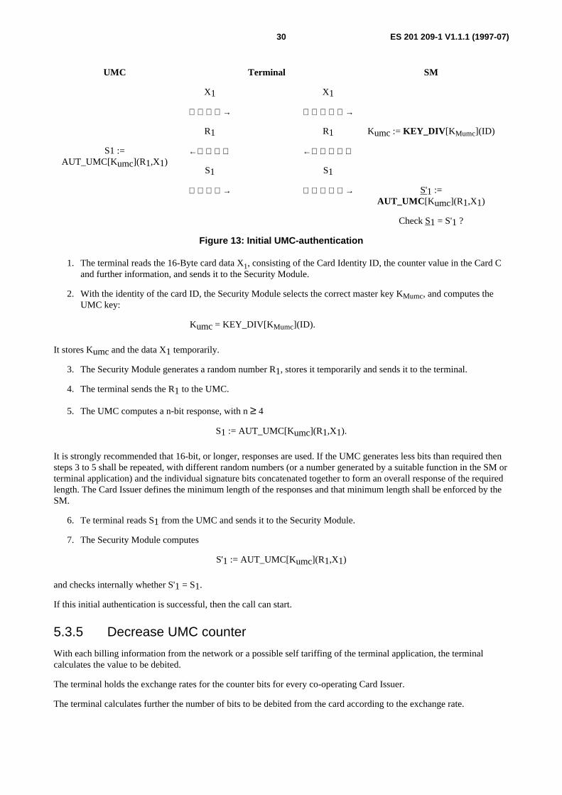
ES 201 209-1 V1.1.1 (1997-07)30
UMC
S1 :=AUT_UMC[Kumc](R1,X1)
X1
→
R1
←
S1
→
Terminal
X1
→
R1
←
S1
→
SM
Kumc := KEY_DIV [KMumc](ID)
S'1 :=AUT_UMC [Kumc](R1,X1)
Check S1 = S'1 ?
Figure 13: Initial UMC-authentication
1. The terminal reads the 16-Byte card data X1, consisting of the Card Identity ID, the counter value in the Card Cand further information, and sends it to the Security Module.
2. With the identity of the card ID, the Security Module selects the correct master key KMumc, and computes theUMC key:
Kumc = KEY_DIV[K Mumc](ID).
It stores Kumc and the data X1 temporarily.
3. The Security Module generates a random number R1, stores it temporarily and sends it to the terminal.
4. The terminal sends the R1 to the UMC.
5. The UMC computes a n-bit response, with n ≥ 4
S1 := AUT_UMC[Kumc](R1,X1).
It is strongly recommended that 16-bit, or longer, responses are used. If the UMC generates less bits than required thensteps 3 to 5 shall be repeated, with different random numbers (or a number generated by a suitable function in the SM orterminal application) and the individual signature bits concatenated together to form an overall response of the requiredlength. The Card Issuer defines the minimum length of the responses and that minimum length shall be enforced by theSM.
6. Te terminal reads S1 from the UMC and sends it to the Security Module.
7. The Security Module computes
S'1 := AUT_UMC[Kumc](R1,X1)
and checks internally whether S'1 = S1.
If this initial authentication is successful, then the call can start.
5.3.5 Decrease UMC counter
With each billing information from the network or a possible self tariffing of the terminal application, the terminalcalculates the value to be debited.
The terminal holds the exchange rates for the counter bits for every co-operating Card Issuer.
The terminal calculates further the number of bits to be debited from the card according to the exchange rate.
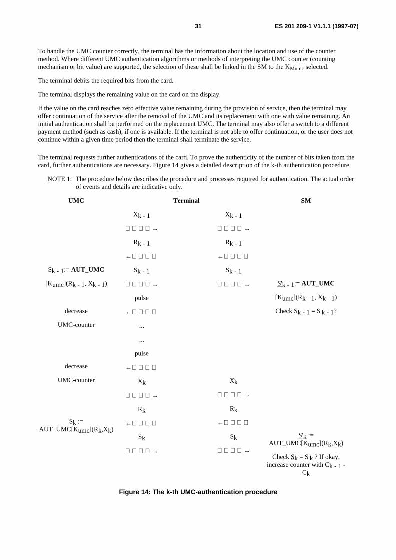
ES 201 209-1 V1.1.1 (1997-07)31
To handle the UMC counter correctly, the terminal has the information about the location and use of the countermethod. Where different UMC authentication algorithms or methods of interpreting the UMC counter (countingmechanism or bit value) are supported, the selection of these shall be linked in the SM to the KMumc selected.
The terminal debits the required bits from the card.
The terminal displays the remaining value on the card on the display.
If the value on the card reaches zero effective value remaining during the provision of service, then the terminal mayoffer continuation of the service after the removal of the UMC and its replacement with one with value remaining. Aninitial authentication shall be performed on the replacement UMC. The terminal may also offer a switch to a differentpayment method (such as cash), if one is available. If the terminal is not able to offer continuation, or the user does notcontinue within a given time period then the terminal shall terminate the service.
The terminal requests further authentications of the card. To prove the authenticity of the number of bits taken from thecard, further authentications are necessary. Figure 14 gives a detailed description of the k-th authentication procedure.
NOTE 1: The procedure below describes the procedure and processes required for authentication. The actual orderof events and details are indicative only.
UMC
Sk - 1:= AUT_UMC
[Kumc](Rk - 1, Xk - 1)
decrease
UMC-counter
decrease
UMC-counter
Sk :=AUT_UMC[Kumc](Rk,Xk)
Xk - 1
→
Rk - 1
←
Sk - 1
→
pulse
←
...
...
pulse
←
Xk
→
Rk
←
Sk
→
Terminal
Xk - 1
→
Rk - 1
←
Sk - 1
→
Xk
→
Rk
←
Sk
→
SM
S'k - 1:= AUT_UMC
[Kumc](Rk - 1, Xk - 1)
Check Sk - 1 = S'k - 1?
S'k :=AUT_UMC[Kumc](Rk,Xk)
Check Sk = S'k ? If okay,increase counter with Ck - 1 -
Ck
Figure 14: The k-th UMC-authentication procedure

ES 201 209-1 V1.1.1 (1997-07)32
It is assumed, that the authentication for k-1 has been successful. Then, after a certain number of pulses, a subsequentauthentication is executed as follows:
1. The terminal reads up to 16-Byte data Xk, consisting of the card identity ID, the current counter Ck and furtherdata out of the EEPROM of the UMC, or at least the data that should change, and sends it to the SecurityModule.
2. The Security Module stores Xk temporarily.
3. The Security Module generates a random number Rk, stores it temporarily and sends it to the terminal. It is notessential that the random number, Rk, is different from the previous value, Rk-1, for one UMC if some other datain the calculation has changed.
4. The terminal sends the Rk to the UMC.
5. The UMC computes a n-bit response, with n ≥ 4.
Sk := AUT_UMC[Kumc](Rk, Xk).
It is strongly recommended that 16-bit, or longer, responses are used. If the UMC generates less bits than required thensteps 3 to 5 should be repeated, with different random numbers (or a number generated by a suitable function in the SM)and the individual signature bits concatenated together to form an overall response of the required length. The CardIssuer defines the minimum length of the responses and that minimum length shall be enforced by the SM (see annex E).
6. The terminal reads Sk from the UMC and sends it to the Security Module.
7. The Security Module computes
S'k := AUT_UMC[Kumc](Rk,Xk)
and checks internally whether S'k = Sk.
8. If the check is correct, then the Security Module increases the counter corresponding to KMumc by the differenceof the last two counter values
Ck - Ck-1,
where Ck-1 is the UMC counter value read at the previous authentication. The terminal lets the service continue.
In the case of an unsuccessful authentication the service is aborted by the terminal and the counter in the SecurityModule is not updated for the last change (Ck - Ck-1). Hence, with this procedure the counter in the Security Module isupdated if and only if two consecutive authentication procedures were successful.
NOTE 2: Thus if an authentication fails or can not be performed (e.g. because the user has removed the UMC) thenCk and hence Ck - Ck-1 can not be computed. The system/terminal operator can not claim any money forthis final amount and is therefore at risk for this amount. Thus it is an advantage for the system/terminaloperator to ensure that the terminal authenticates and decrements the UMC frequently, preferably forevery metering event.
For subsequent authentications with changed counters it might be sufficient to use the same random for eachauthentication. In the case of enhanced security by repeated authentication to enlarge the number of response bits, it isnecessary to use different random numbers.
5.3.6 Increase SM counter
For each Card Issuer the Security Module handles one, or more, counters summing up all units debited from cards ofthis Card Issuer. One of the important functions of the Security Module is to ensure, that the counter(s) for a certainCard Issuer are only increased by a certain value, if a signed message of an UMC is received, proving that the counter ofthe UMC is decreased by the same value. Therefore it is necessary that the Security Module is able to interpret thecounter value for all Card Issuers for which it is handling cards.
ES 201 209-1 V1.1.1 (1997-07)33
For instance, if a Card Issuer issues different series of UMCs for which the bits on the UMCs represent differentmonetary values then different SM counters are necessary.
In this case, the selection of the SM counter shall be securely linked to the selected KMumc within the Security Module,to prevent an incorrect value being claimed. UMCs for which different bits represent different monetary values shall usea different KMumc.
5.3.7 Extract counter from the SM
As mentioned in the previous subclause the SM handles counters for each Card Issuer. These counters are extracted witha signature. The key used for this signature is the MAC key, chosen by the Card Issuer and not known in plain to thesystem operator. The billing between system operator and Card Issuer is based on these counters. The billing process isdescribed in subclauses 4.7 and 5.4. Annex H describes an example method of MAC generation. A unique identificationof the counter shall be used in the MAC calculation. This shall consist at least of the unique identity of the SM and theunique identity of the counter within the SM (e.g. containing the full path of the counter file). The use of thisinformation shall be secured within the SM to ensure the correct identification is used.
5.4 Payment and settlement
Trusted ThirdParty
Card
Management system
Operator's
Management system
TerminalApplication
UMCSecurity
Module
12
3
5
6
4
Storage of counters
Secure readout of counters
Information collection
Check of
and invoicing
counter MAC
A
Figure 15: The billing and accounting interface model
For secure billing the boxes highlighted in figure 15 are relevant. In more detail the following steps take place for securebilling:
- The counters and MACs are periodically read out of the Security Module and transferred to a central billingsystem.
The Data elements "counter_value" and "MAC" are described in subclause 6.8.1.
- The billing system stores for each Security Module the data elements "counter_value" and "MAC" for the firstday of a billing period and the data element "counter and MAC" for the current day.
- After the end of a billing period the two data elements "counter_value" and "MAC" for the first day of a billingperiod and the data elements "counter_value" and "MAC" for last day of a billing period are stored. Thedifference between the two counters is the consumed value of the billing period.
- The billing system adds all data elements "consumed values of a SM". That summary is the basis for a bill.

ES 201 209-1 V1.1.1 (1997-07)34
- The Card Issuer will receive all data elements "counter_value" and "MAC" for the first day of a billing periodand the data elements "counter_value" and "MAC" for last day.
- The Card Issuer may check the MAC and then if correct, the summary minus an agreed amount is then paid to theoperator.
- For further billing periods the start value will be the value of the last day of the foregoing period.
For the secure counter readout see subclause 5.3.7.
An alternative billing arrangement may be used by bilateral agreement between an operator and a Card Issuer.
5.5 Operational differences for network based SMThe Security Module can also be located outside of the terminal (see EN 726-7 [2]). Figure 16 (taken fromEN 726-7 [2]) shows the 3 different possible configurations. This choice can be made for security reasons (e.g. todecrease the risk of SM theft) or for economic reasons (e.g. sharing an SM between different terminals). This leads tothe need to consider further requirements on the SM to deal with other constraints and functions.
UMC CardTerminal
SMSM included in the Terminal
UMC Card Terminal
SM
UMC Card TerminalSM included in a local concentrator
UMC Card TerminalSM
NetworkSM in the network
UMC Card TerminalNetwork
SM
SM remote accessed across a network
a)
b)
c)
d)
NOTE: These network based Security Module configurations are taken from EN 726-7 [2].
Figure 16: Network based SM configurations
Configuration a) is the one covered by other parts of this document. The main differences required if configurations b),c) or d) are adopted are covered in this subclause.
The major difference is that the SM is shared in order to manage different terminals, thus allowing a decrease in the totalnumber of SMs required for a given number of terminals.
This leads to the need to consider "parallel" authentication processing of different cards in different terminals. Thisintroduces the requirement for the management of a context mechanism allowing the creation and retrieval of thenecessary environment for management of one card process amongst others.
ES 201 209-1 V1.1.1 (1997-07)35
Data elements to be stored in each context shall allow access to the relevant data, counter and key file(s).
The ability to perform parallel processing also implies that the SM has to process faster than for an SM dealing withonly a single terminal. In order to reduce the processing time numerous card management specific commands(essentially macro commands) could be used.
Location of the SM in the network allows management of terminals of different operators by one SM (e.g. in the case ofprivate terminal operators). In order to deal with this case and with the corresponding demands for secure settlement, itis necessary to provide the terminal operator with its own DF and necessary keys (i.e. at least the Kload and KMAC keys).
As the data link between the UMC and the SM may not be continuously available during the provision of service period,the signature process by the UMC and SM verification could be made at different time periods. It is stronglyrecommended that in this case the terminals are authenticated by the SM to ensure that the correct DFs are used, and thatthe terminals can not be masqueraded.
6 Data elements
6.1 Data description techniqueIn this subclause Abstract Syntax Notation One (ASN.1) (ITU-T Recommendations X.680 and X.682 [14, 15]) is usedpurely as a means of describing the data elements in a succinct manner, yet precise enough for the purpose. WhereASN.1 is used it lists whether data elements are mandatory or optional, and gives guidelines for how they might bestructured. The exact structure of the data elements is not mandated. The interface specifications do not contain all thedetail that would be required to completely specify each interface in an interoperable manner. Complete interfaceprotocols could be specified that included the data elements given here. Such specifications could also include other dataelements to complete the protocol. ASN.1 could be used for these complete specifications and the standardized encodingrules (ITU-T Recommendations X.690 and X.691 [16, 17]) could be applied to obtain the bit patterns actuallyexchanged. However, the use of other data description techniques and encoding methods are not precluded by thisdocument for these more detailed interface specifications.
6.2 System operator/Card Issuer interface (Interface 4)The Card Issuer shall provide all the system operators, with which they have an agreement, information on UMCs(or UMC batches) which have been stopped because they have been reported stolen or are thought to be being usedfraudulently (the blacklist).
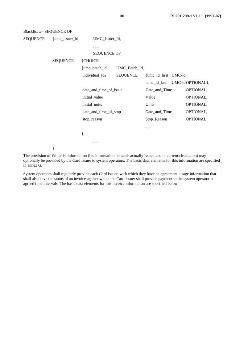
ES 201 209-1 V1.1.1 (1997-07)36
Blacklist ::= SEQUENCE OF
SEQUENCE {umc_issuer_id UMC_Issuer_Id,
. . .,
SEQUENCE OF
SEQUENCE {CHOICE
{umc_batch_id UMC_Batch_Id,
individual_Ids SEQUENCE {umc_id_first UMC-id,
umc_id_last UMC-idOPTIONAL},
date_and_time_of_issue Date_and_Time OPTIONAL,
initial_value Value OPTIONAL,
initial_units Units OPTIONAL,
date_and_time_of_stop Date_and_Time OPTIONAL,
stop_reason Stop_Reason OPTIONAL,
. . .
},
. . .
}
The provision of Whitelist information (i.e. information on cards actually issued and in current circulation) mayoptionally be provided by the Card Issuer to system operators. The basic data elements for this information are specifiedin annex G.
System operators shall regularly provide each Card Issuer, with which they have an agreement, usage information thatshall also have the status of an invoice against which the Card Issuer shall provide payment to the system operator atagreed time intervals. The basic data elements for this invoice information are specified below.
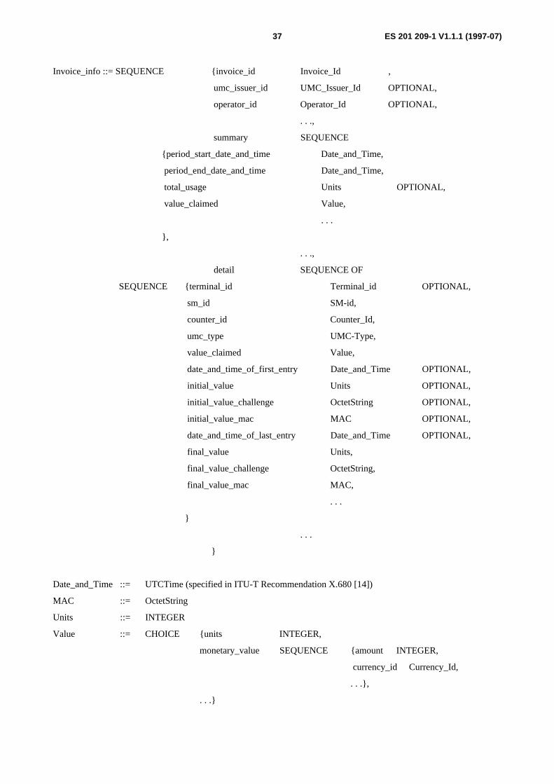
ES 201 209-1 V1.1.1 (1997-07)37
Invoice_info ::= SEQUENCE {invoice_id Invoice_Id ,
umc_issuer_id UMC_Issuer_Id OPTIONAL,
operator_id Operator_Id OPTIONAL,
. . .,
summary SEQUENCE
{period_start_date_and_time Date_and_Time,
period_end_date_and_time Date_and_Time,
total_usage Units OPTIONAL,
value_claimed Value,
. . .
},
. . .,
detail SEQUENCE OF
SEQUENCE {terminal_id Terminal_id OPTIONAL,
sm_id SM-id,
counter_id Counter_Id,
umc_type UMC-Type,
value_claimed Value,
date_and_time_of_first_entry Date_and_Time OPTIONAL,
initial_value Units OPTIONAL,
initial_value_challenge OctetString OPTIONAL,
initial_value_mac MAC OPTIONAL,
date_and_time_of_last_entry Date_and_Time OPTIONAL,
final_value Units,
final_value_challenge OctetString,
final_value_mac MAC,
. . .
}
. . .
}
Date_and_Time ::= UTCTime (specified in ITU-T Recommendation X.680 [14])
MAC ::= OctetString
Units ::= INTEGER
Value ::= CHOICE {units INTEGER,
monetary_value SEQUENCE {amount INTEGER,
currency_id Currency_Id,
. . .},
. . .}

ES 201 209-1 V1.1.1 (1997-07)38
Currency_Id ::= PrintableString (SIZE 3) DEFAULT "ECU"
- - The value shall be a 3 letter currency code taken from ISO 4127 [5]
The Card Issuer provides cryptographic keys in a secure manner. They are entered into the SM by means of the keymanagement and maintenance process described in subclause 4.6.
Key&P_Download_Data ::= SEQUENCE
{sm_Id CHOICE {sm_Id SM_Id,
sm_Id_list SET OF SM-Id,
all NULL,
. . .
} OPTIONAL,
encrypted_keys SET OF SEQUENCE
{key_type ENUMERATED {kload, kMAC, kMumc, kMcer, . . .},
version_no INTEGER OPTIONAL,
encrypted_key BIT STRING,
mac BIT STRING,
. . .
},
. . .
}
It is recommended that at least 3 versions of KMumc are supported. Optionally if certificates are supported then it isrecommended that at least 4 versions of KMcer are supported.
Additional data may need to be transferred between the Card Issuer and the system operator. For example, data to linkkeys, algorithms and counting methods. Details of how this data is transferred are not specified here.
6.3 Operator's Management System (OMS)/terminal applicationinterface (Interface 3)
If the operating management system is owned by a different party from that owning the terminal then the interfacebetween them shall fulfil the requirements of this document.
If they are both owned by the same party then implementation details are a local matter. However, even in this case theinterface has to be capable of meeting the information exchange requirements of this document such that it is possible toconfirm to the other interfaces and the required functionality.
The physical, electrical and lower layer protocol aspects of this interface are not constrained by this document. (Theyare for further study).
When communication is established between the Management system and the terminal, it is recommended that thereshall be a mutual authentication exchange before any other data is transferred. If this fails for either party then that partyshall abort the communication. Periodic re-authentication may take place, or a continuous authentication mechanismmay be used. All information exchanged should be classified. Depending on the classification level, security may beapplied to ensure the integrity and confidentiality of the data as appropriate to its classification.

ES 201 209-1 V1.1.1 (1997-07)39
Information to be conveyed in the direction Operator's Management System to Terminal Application:
request for a particular counter value
request for all counter values optional
read tariff table optional
load tariff table
read currency conversion table optional
load currency conversion table
request call records optional
read blacklist optional
load blacklist
incremental update to blacklist optional
download new key
download application to SM optional
download new software to the terminal optional
load table of accepted cards
acknowledge alarm information
Information to be conveyed in the direction Terminal Application to Operator's Management System:
response to request for a particular counter value
response to request for all counter values optional
response to read tariff table optional
response to load tariff table
response to read currency conversion table optional
response to load currency conversion table
response to request call records optional
response to read blacklist optional
response to load blacklist
response to incremental update to blacklist optional

ES 201 209-1 V1.1.1 (1997-07)40
response to download new key
response to download application to SM optional
response to download new software to the terminal optional
response to load table of accepted cards
send alarm information
Additional optional information may be exchanged with either end initiating the transfer.
6.4 Terminal/UMC interface (Interface 2)The physical and electrical aspects of this interface shall be as specified in ISO 7816-1, -2 and -3 (section 1 to 4.2.7) [6,7 and 8].
NOTE 1: The synchronous protocol and command set are not fully specified in ISO 7816-3 [8]. Thus thisInternational Standard is usually augmented by proprietary specifications. There are presently no publiclyavailable specifications or standards that fully specify the UMC to terminal interface.
The UMC can not issue commands to the terminal; it can only respond to commands from the terminal. The terminalissues commands and associated data to the UMC by asserting combinations of electrical signals on the electricalcontacts on the card (see ISO 7816-2 [7] and proprietary specifications).
In User configuration the minimum command set available is:
AUTHENTICATE;
RESET;
READ;
WRITE;
ERASE.
Data-elements handed over through this interface shall support the card recognition and card authentication processes.Optionally other processes may be supported.
Following data elements shall be interchanged to support authentication operations:
from UMC to terminal:
- UMC_data:
- identification data ID: 64 bits, these are the first 64 bits of the UMC-memory area;
- current counter C value (see annex D);
- additional data D, also written on the card.
NOTE 2: The counting method and the location of the counter have to be determined from the card recognitionprocess and data provided by the Card Issuer.
Following data elements may optionally be transmitted from UMC to the terminal to support other functions. It ispossible that these data elements are part of the additional data D.
- Certificate CER, written on the card, used to validate the card (passive authentication): 16 bits;
- face value (i.e., the initial value on the card);
- expiry date;

ES 201 209-1 V1.1.1 (1997-07)41
- flag for counter value less than face value;
- empty flag;
- FND number;
- currency indicator;
- counter backup (i.e. an anti-tearing mechanism);
- other additional data;
from terminal to UMC:
- random R: 32 or 48 bits;
from UMC to terminal:
- signature S, calculated by the card as a function of (Kumc, UMC_data, R): 4, 8, 12 or 16 bits.
6.5 Data elements to be held in the UMCUMC_DATA ::= SET {
icc_identification ICC_Identification,
icc_type ICC_Type OPTIONAL,
face_value Face_Value OPTIONAL,
personalisation_flag BOOLEAN,
counter Counter,
anti_tearing_flags Anti_tearing_flags,
authentication_key_Kumc Authentication_key_Kumc,
first_use_flag BOOLEAN OPTIONAL,
empty_flag BOOLEAN OPTIONAL,
reload_flag BOOLEAN OPTIONAL,
currency_id Currency_Id OPTIONAL,
master_key_identifier Master_key_identifier OPTIONAL,
expiry_date Expiry_date OPTIONAL,
certificate Certificate OPTIONAL,
card_invalid_flag BOOLEAN OPTIONAL,
services SEQUENCE OF CHOICE {
fnd_option SEQUENCE {national_call_flag BOOLEAN,
fnd_number FND_Number,
. . .
}
. . .
} OPTIONAL,
. . .

ES 201 209-1 V1.1.1 (1997-07)42
}
The data element "ICC_Identification" may include information to identify the type of IC, Card Issuer and other datasuch as a unique serial number.
6.6 Terminal/SM interface (Interface 1)
6.6.1 Preparation and selection
The terminal needs to select the information for a particular Card Issuer when issuing commands to the SM. Twodifferent ways of achieving this are recommended.
a) The terminal may issue a "Select" command to the SM. All subsequent commands to the SM are governed by thisselect command until another "Select" command is issued. This mode of operation minimizes the amount of datatransferred between the terminal and the SM.
b) The select information may be included with each command to the SM. This mode of operation allows commandsconcerning different UMCs to be interleaved.
The application may be selected using Application identifiers (registered under the procedures given inISO 7816-5 [10]) or using information related to an UMC issuer.
6.6.2 UMC authentication
The minimum data to be exchanged between the terminal and the SM in order to achieve the UMC authentication is thefollowing.
The terminal initiates the sequence by requesting the SM to generate a random number and by providing the necessaryUMC data to the SM. Then the SM replies with the answer "OK" or "Not OK" only.
Authenticate_UMC_request ::= SET
{umc_data SET {umc_identification Identification_Area,
umc_counter Counter,
umc_ad_data Data_Area OPTIONAL,
. . .
} OPTIONAL,
master_key_id SET {umc_issuer_Application_id Umc_Issuer_Aid,
master_key_File_Id Master_Key_Ef_Id,
master_key_number Key_Num,
. . .
},
random_number Bit String,
umc_signature Bit String,
. . .
}
The master key has to be diversified internally by the SM with the UMC information and an appropriate algorithm givenas a parameter or implicitly chosen.

ES 201 209-1 V1.1.1 (1997-07)43
NOTE: This data element can be used in different ways and in either direction of data flow. No particularsequence of information transfer is implied by the structure of this data element.
Authenticate_UMC_response ::= SET
{ result ENUMERATED {positive, negative, . . .}
. . .
}
6.6.3 Counter increase
The following set of data presents the minimum information to be exchanged between the terminal and the SM in orderto achieve the secure increase of a counter.
The basic condition to achieve this function is to have already successfully authenticated the UMC (see previoussubclause). This scheme supposes that the SM is able to calculate the difference between the previous value of the UMCCounter area and the current one. The security of this operation relies on the UMC signature. The SM replies "OK" or"Not OK".
Increase_Counter_request ::= SET
{umc_counter UMC_Counter_Value,
counter_id Counter_Id OPTIONAL,
random_number Bit String,
umc_signature Bit String,
. . .
}
NOTE: Some of these data elements may be stored in the SM and implicitly selected.
Increase_Counter__response ::= SET
{ result ENUMERATED {positive, negative, . . .}
. . .
}
6.7 Data elements to be held in the SMAn SM is a device containing logically and physically protected secrets such as algorithms and related keys. The SMitself needs to operate in such away, and be the subject of strict security procedures such that unauthorized access isrendered infeasible or prohibitively costly compared to the benefits gained.
The following description is aimed at describing the minimum information set needed to achieve the required datasecurity.
It shall not be possible to read certain secret information, particularly key values and algorithm parameters out of theSM.

ES 201 209-1 V1.1.1 (1997-07)44
SM_DATA ::= SET
{key_set SET {
key_Mttp SEQUENCE {key_Mttp_version INTEGER OPTIONAL,
kMttp KEY,
algo_Id Algo_Id OPTIONAL,
algo_params Algo_params OPTIONAL,
. . . } OPTIONAL,
. . . },
sm_identification SET {sm_id SM_id,
sm_manufacturer_id SM_MAN_id
. . . },
. . .,
card_issuer_data SEQUENCE OF SET
{card_issuer_id SET {umc_issuer_idUMC_issuer_id,
umc_issuer_Application_id UMC_ISSUER_AId
. . . },
{key_set SET {
key_ttp SEQUENCE {key_ttp_version INTEGER OPTIONAL,
KTTP KEY,
algo_Id Algo_Id OPTIONAL,
algo_params Algo_params OPTIONAL,
. . . },
key_load SEQUENCE {key_load_version INTEGER,
kload KEY,
kl_algo_Id Algo_Id OPTIONAL,
kl_algo_params Algo_params OPTIONAL,
. . . },
key_mac SEQUENCE {key_mac_version INTEGER,
kmac KEY,
km_algo_Id Algo_Id OPTIONAL,
km_algo_params Algo_params OPTIONAL,
. . . },
- - other keys could be added
. . . }
key_Mumc SEQUENCE OF SEQUENCE
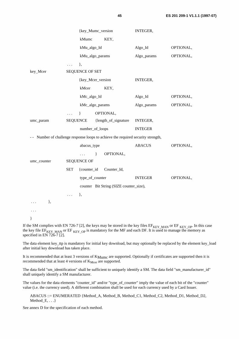
ES 201 209-1 V1.1.1 (1997-07)45
{key_Mumc_version INTEGER,
kMumc KEY,
kMu_algo_Id Algo_Id OPTIONAL,
kMu_algo_params Algo_params OPTIONAL,
. . . },
key_Mcer SEQUENCE OF SET
{key_Mcer_version INTEGER,
kMcer KEY,
kMc_algo_Id Algo_Id OPTIONAL,
kMc_algo_params Algo_params OPTIONAL,
. . . } OPTIONAL,
umc_param SEQUENCE {length_of_signature INTEGER,
number_of_loops INTEGER
- - Number of challenge response loops to achieve the required security strength,
abacus_type ABACUS OPTIONAL,
. . . } OPTIONAL,
umc_counter SEQUENCE OF
SET {counter_id Counter_Id,
type_of_counter INTEGER OPTIONAL,
counter Bit String (SIZE counter_size),
. . . },
. . . },
. . .
}
If the SM complies with EN 726-7 [2], the keys may be stored in the key files EFKEY_MAN or EF KEY_OP. In this casethe key file EFKEY_MAN or EF KEY_OP is mandatory for the MF and each DF. It is used to manage the memory asspecified in EN 726-7 [2].
The data element key_ttp is mandatory for initial key download, but may optionally be replaced by the element key_loadafter initial key download has taken place.
It is recommended that at least 3 versions of KMumc are supported. Optionally if certificates are supported then it isrecommended that at least 4 versions of KMcer are supported.
The data field "sm_identification" shall be sufficient to uniquely identify a SM. The data field "sm_manufacturer_id"shall uniquely identify a SM manufacturer.
The values for the data elements "counter_id" and/or "type_of_counter" imply the value of each bit of the "counter"value (i.e. the currency used). A different combination shall be used for each currency used by a Card Issuer.
ABACUS ::= ENUMERATED {Method_A, Method_B, Method_C1, Method_C2, Method_D1, Method_D2,Method_E, . . .}
See annex D for the specification of each method.

ES 201 209-1 V1.1.1 (1997-07)46
If the Security Module covers requirements of EN 726-7 [2] then the data elements could be presented as follows:
AC AC AC
AC
AC
TerminalOperator
EFKEY_MANSM
EFKEY_OPSM
EFDIRSM
AC
EFICCSM
AC AC AC
EFcounter1UMC_1 OP1
EFcounter2UMC_2 OP1
EFcounterX
AC
AC
EFKEY_MANSM
EFKEY_OPUMC
AC
AC AC AC
EFcounter1UMC_1 OP2
EFcounter2UMC_2 OP2
EFcounterXUMC_x OP2
UMC ISSUER 1AC
EFKEY_OPSM
AC
UMC ISSUER 2
EFAbacusParam
UMC_x OP1
AC
AC
EFKEY_MANSM
EFKEY_OPUMC
AC
EFKEY_OPSM
ACEF
AbacusParam
Figure 17: Example Security Module file map
6.8 SM/system interface (Interface 1 or A)If Interface A is implemented then these data elements are passed over that interface, otherwise they flow overInterface 1 (see figure 1).
6.8.1 Counter extraction with a MAC
The following set of data presents the minimum information to be exchanged between the terminal and the SM in orderto achieve extraction of a secured counter with an associated MAC.

ES 201 209-1 V1.1.1 (1997-07)47
MAC_Counter_request ::= SET
{card_issuer_id Card_Issuer_Id OPTIONAL,
sm_id SM_Id OPTIONAL,
counter_id Counter_Id OPTIONAL,
mac_key_num Key_Num OPTIONAL,
initial_value Initial_Value OPTIONAL,
. . .
}
MAC_Counter_response ::= SET
{card_issuer_id Card_Issuer_Id OPTIONAL,
sm_id SM_Id,
counter_id Counter_Id,
mac_key_num Key_Num OPTIONAL,
initial_value Initial_Value OPTIONAL,
counter_value Bit String (SIZE counter_size) OPTIONAL,
mac Bit String OPTIONAL,
result ENUMERATED {positive, negative, . . .},
. . .
}
The Security Module shall use the SM_Id and Counter_Id, plus any "initial value" on the request, as initial values to befed into the MAC computation.
A globally unique identification of that counter (such as a globally unique SM identifier ("SM-Id") plus a local counteridentifier) shall be included in the MAC calculation, plus optionally an "Initial_Value" that includes at least a randomnumber or sequence number.
A unique identification of the counter shall be used in the MAC calculation. This shall consist at least of the uniqueidentity of the SM (SM_Id) and the unique identity of the counter (Counter_Id) within the SM (e.g. containing the fullpath of the counter file). The use of this information shall be secured within the SM to ensure the correct identification isused.
6.8.2 Download a key
The following set of data represents the minimum information to be exchanged between the terminal and the SM todownload a new key into an existing key location.
The key to be loaded is enciphered and signed to achieve both confidentiality and authenticity during thecommunication. This is performed by a strong enough algorithm and a key (Kload) present both in the Card Issuermanagement system and in the SM.
The SM shall not disclose any information which could be used for cryptographic analysis other than the final binaryanswer "OK" or "Not OK" and status messages as specified in EN 726-3 [1].

ES 201 209-1 V1.1.1 (1997-07)48
Download_Key_request ::= SET
{ciphered_key Bit String,
mac Bit String OPTIONAL,
key_location_num Key_Location_Num,
key_file_id Key_File_Id,
key_to_change Key_Num OPTIONAL,
key_version_number Key_Version_Number OPTIONAL,
. . .
}
If the explicit MAC field is omitted, then some other mechanism shall be used to ensure the integrity of the key, such asredundancy in the key.
Download_Key_response ::= SET
{ result ENUMERATED {positive, negative, . . .}
. . .
}
7 Compliance with the terms of this documentThis document specifies a system architecture for achieving interoperability of pre-paid memory type smart cards(known as User Memory Cards or UMCs). That is various entities can issue these cards and they can be used interminals operated by various other entities. For this system to work it is necessary for each card issuing entity to have atechnical and commercial agreement with one, or more, entities operating terminals. The cards issued by an issuer canonly be used in the terminals operated by entities with which the issuer has such an agreement. This needs to be madeclear by Card Issuers to their customers. Thus the system architecture specified provides for limited interoperabilityrather than universal interoperability.
This architecture could be applied by a single commercial entity that performed all the different roles specified in thisdocument. If the provisions of this document are faithfully applied then that entity would conform to the provisions ofthis document. However, the architecture defines different roles. Different commercial entities can perform the functionsof the different roles and co-operate to fulfil the provisions of this document.
The main roles defined in this document are:
- system operator;
- Card Issuer;
- SM manufacturer;
- UMC user;
- Trusted Third Party (TTP).
An entity only needs to comply with the provisions of this document that apply to the role or roles that it claims toperform.
This document also specifies the system components and interfaces between these components that comprise the overallsystem architecture. An implementor of a system component specified in this document only has to comply with thefunctions and interfaces specified that apply to that system component. The main system components and interfacesbetween them are shown in figure 1.
This document only specifies the interfaces between system components at a relatively high level of abstraction. Otherspecifications may specify these interfaces and associated functions in more detail. These other specifications complywith this document if they provide for the functions and transfer of information specified in this document. They may

ES 201 209-1 V1.1.1 (1997-07)49
provide extra features not explicitly specified in this document. They shall not provide any features or informationtransfer explicitly or implicitly prohibited by this document.
NOTE: Other specifications may reference this document and claim compliance with it under the terms of thisclause. These specifications may be international, regional, national or proprietary in nature.

ES 201 209-1 V1.1.1 (1997-07)50
Annex A (normative):Security requirements
A.1 GeneralThe Partners want to achieve mutual acceptance of UMCs in their telecommunication systems. It ismandatory to use a secure transfer mechanism for the transfer of keys (see annex B) The creation of the keysis the task of a TTP.
Problem: The level of trust of the TTP shall be evident. The confidentiality and the quality of the Keysshall be ensured.
A.2 Security requirements on the TTPIn this clause the keys referred to are the initial loading key and any others required.
1) Secure generation, administration, and storage of keys for a Partner.
2) Secure hand over of keys to other parties e.g. secure loading of Keys into the Secure Devices (SD) - if used.
3) Secure loading of Keys into the Security Modules.
4) Additional security measures for secure data handling e.g. CHV and PIN creation and administration.
5) Physical protection of the TESA-7 algorithms.
To fulfil the role the TTP has to use software and hardware. This software and hardware, and their physical location aresubject to the following requirements:
6) It shall be ensured, that only authorized persons are able to start the personalization software.
7) In general any unauthorized modification of data or keys shall be prevented. It shall be possible to recognizeunauthorized actions, e.g. audit trails.
8) Access control mechanisms shall guarantee the confidentiality of keys and other protected data. The logicaland/or physical storage of keys shall be secure.
9) The generation of keys shall be secure. The use of weak keys shall be prevented. It is important to verifyrandom number generator.
10) Every personalization action shall be evident.
11) The software and hardware environments have to be considered.
To find out the level of trust, an ITSEC Evaluation of the TTP Software should be done. The minimumevaluation level should be at least E2 and the minimum strength of mechanisms should be medium.
12) It shall be ensured that only trustworthy personnel is employed.
13) Protection of buildings and rooms against criminal actions shall be ensured.
14) In order to prevent unauthorized external access to the personalization software the personalization deviceshould not be connected to an external network. If a network solution is necessary the physical and thereforealso the logical connection of the personalization device should be limited to the secure personalizationenvironment.
To find out the coverage of these minimum physical and organisational security requirements, an audit of thelocation of the TTP should be done.
ES 201 209-1 V1.1.1 (1997-07)51
A.3 Basic security requirementsThe SM shall comply with the following security requirements.
Req 1 The SM operating system (mask) shall ensure the integrity and confidentiality of the initialization key(s) (e.g.KTTP), the UMC algorithms and all the keys and data belonging to a Card Issuer. These keys, UMCalgorithms, and confidential data shall remain secret in the SM and shall not be communicated outside theSM. Any program code downloaded shall comply with these requirement too.
Req 2 The mask shall ensure the integrity and confidentiality of each Card Issuer's secure and confidential storing ofcryptographic keys and confidential data towards other Card Issuers. These keys and data shall remain secretin the SM. Any program code downloaded shall comply with these requirement too.
Req 3 Creation, deletion of a Card Issuer, cryptographic key loading and code downloading shall only be allowedafter successful authentication.
Req 4 The UMC counter in the SM shall not be resetable, it shall only be possible to increment it. The only way toincrement the UMC counter unit in the SM shall only be after two consecutive successful UMCauthentications.
Req 5 The download of any additional software shall be secured under the control of the authorized TTP.
Req 6 The SM shall follow a one way life cycle.
Req 7 The SM shall provide physical and logical mechanisms to fulfil the former requirements.
It is recommended that the system operator provides means to prove to the outside world that the SM mask and all thedownloaded software are authentic. The nature of this proof and the procedures to be followed are subject to bilateralagreement (see annex E item 21).
In order to meet these requirements, the mask, the additional downloaded software and the chip shall implement adaptedsecurity enforcing functions and mechanisms. Appropriate confidence in these functions will be needed.
To provide this confidence, it is mandatory that a security evaluation and certification (e.g. ITSEC [18]) shall becompleted according to a bilateral agreement. The Target Of Evaluation shall include chip, mask and additionaldownloaded software. The security enforcing functions described in the security target shall fulfil the formerrequirements. Typically the evaluation level should be greater or equal to ITSEC E3 and the minimum strength of themechanism high. Each piece of downloaded software shall be evaluated to the same requirements in order to be allowedto be downloaded.
The evaluation report (if produced) shall remain confidential because it contains some confidential information.Depending on bilateral agreement, it shall be possible that some parties exchange the present document.
ES 201 209-1 V1.1.1 (1997-07)52
Annex B (normative):Key transfer proceduresThere are several possibilities for transferring keys. Two methods are described in this annex. Others may be adopted bybilateral agreement (see annex E).
B.1 The procedure for key transfer using a secure deviceIf a secure device is used, then the Card Management System provides an interface for the Secure Device. The tasks ofthe Secure Device are the following:
- In the secure device, the key KTTP is pre-loaded by the TTP.
- The secure device receives the data field Kload in a secure way. It is highly recommended that the CardManagement uses a special central system to handle the cryptographic data. This system should be located in aphysically secured area.
- The secure device encrypts the data field Kload with the recommended algorithm and the data field KTTP that hasbeen previously installed in the SD.
- The encrypted Kload is then handed over to the Card Management system.
- The Kload is installed in the SD for the next steps.
- The data fields KMumc and KMAC are handed over to the SD. Optionally other keys (e.g. certification keyKMcer).
- The SD encrypts the KMumc and KMAC with the Kload.
The hand over of the keys Kload, KMumc and KMAC from the card management system might be realized in encryptedform, i.e. there is a further key handled by the Card Management System and the secure device to encrypt these keys atthe interface.
Due to the fact, that these keys are handled in clear within the secure device, the secure device might transformadditionally the format of the keys.
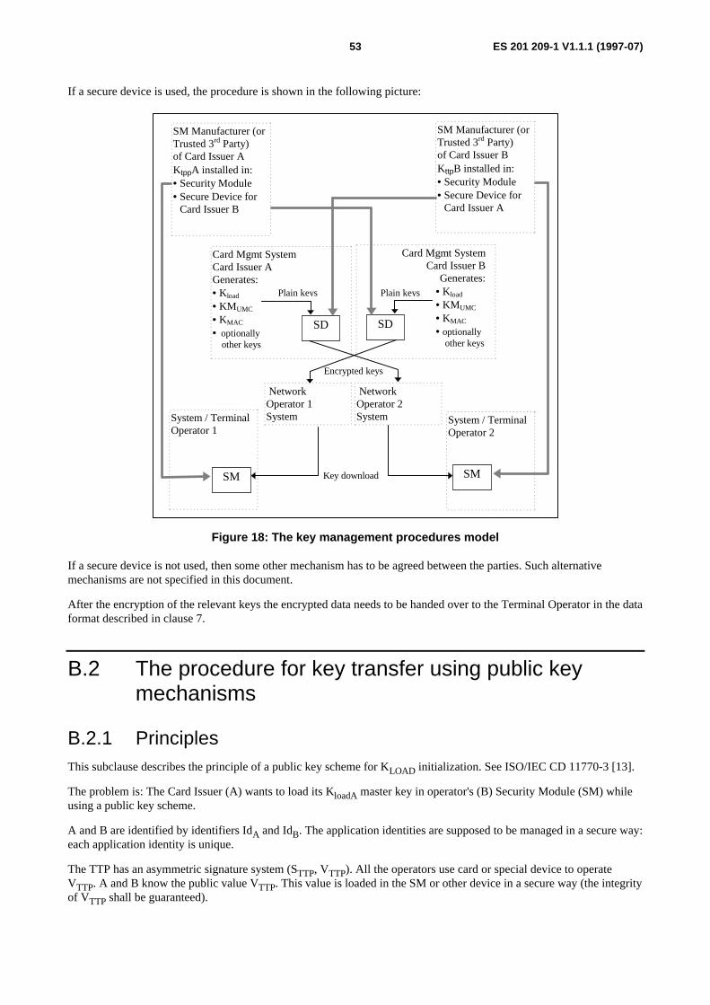
ES 201 209-1 V1.1.1 (1997-07)53
If a secure device is used, the procedure is shown in the following picture:
System / TerminalOperator 1
System / TerminalOperator 2
SM Manufacturer (orTrusted 3rd Party)of Card Issuer AKtppA installed in:• Security Module• Secure Device for
Card Issuer B
SM Manufacturer (orTrusted 3rd Party)of Card Issuer BKttpB installed in:• Security Module• Secure Device for
Card Issuer A
Card Mgmt SystemCard Issuer AGenerates:• Kload
• KMUMC
• KMAC
• optionally other keys
Card Mgmt SystemCard Issuer B
Generates:• Kload
• KMUMC
• KMAC
• optionally other keys
SD SD
SM SM
Encrypted keys
Plain keys
Key download
NetworkOperator 1System
NetworkOperator 2System
Plain keys
Figure 18: The key management procedures model
If a secure device is not used, then some other mechanism has to be agreed between the parties. Such alternativemechanisms are not specified in this document.
After the encryption of the relevant keys the encrypted data needs to be handed over to the Terminal Operator in the dataformat described in clause 7.
B.2 The procedure for key transfer using public keymechanisms
B.2.1 PrinciplesThis subclause describes the principle of a public key scheme for KLOAD initialization. See ISO/IEC CD 11770-3 [13].
The problem is: The Card Issuer (A) wants to load its KloadA master key in operator's (B) Security Module (SM) whileusing a public key scheme.
A and B are identified by identifiers IdA and IdB. The application identities are supposed to be managed in a secure way:each application identity is unique.
The TTP has an asymmetric signature system (STTP, VTTP). All the operators use card or special device to operateVTTP. A and B know the public value VTTP. This value is loaded in the SM or other device in a secure way (the integrityof VTTP shall be guaranteed).
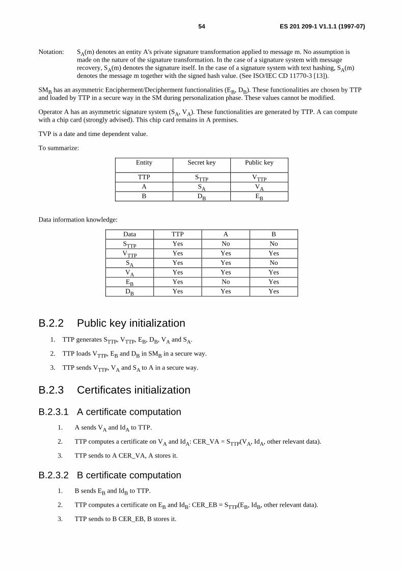
ES 201 209-1 V1.1.1 (1997-07)54
Notation: SA(m) denotes an entity A's private signature transformation applied to message m. No assumption ismade on the nature of the signature transformation. In the case of a signature system with messagerecovery, SA(m) denotes the signature itself. In the case of a signature system with text hashing, SA(m)denotes the message m together with the signed hash value. (See ISO/IEC CD 11770-3 [13]).
SMB has an asymmetric Encipherment/Decipherment functionalities (EB, DB). These functionalities are chosen by TTPand loaded by TTP in a secure way in the SM during personalization phase. These values cannot be modified.
Operator A has an asymmetric signature system (SA, VA). These functionalities are generated by TTP. A can computewith a chip card (strongly advised). This chip card remains in A premises.
TVP is a date and time dependent value.
To summarize:
Entity Secret key Public key
TTP STTP VTTPA SA VAB DB EB
Data information knowledge:
Data TTP A B
STTP Yes No No
VTTP Yes Yes Yes
SA Yes Yes No
VA Yes Yes Yes
EB Yes No Yes
DB Yes Yes Yes
B.2.2 Public key initialization1. TTP generates STTP, VTTP, EB, DB, VA and SA.
2. TTP loads VTTP, EB and DB in SMB in a secure way.
3. TTP sends VTTP, VA and SA to A in a secure way.
B.2.3 Certificates initialization
B.2.3.1 A certificate computation
1. A sends VA and IdA to TTP.
2. TTP computes a certificate on VA and IdA: CER_VA = STTP(VA, IdA, other relevant data).
3. TTP sends to A CER_VA, A stores it.
B.2.3.2 B certificate computation
1. B sends EB and IdB to TTP.
2. TTP computes a certificate on EB and IdB: CER_EB = STTP(EB, IdB, other relevant data).
3. TTP sends to B CER_EB, B stores it.
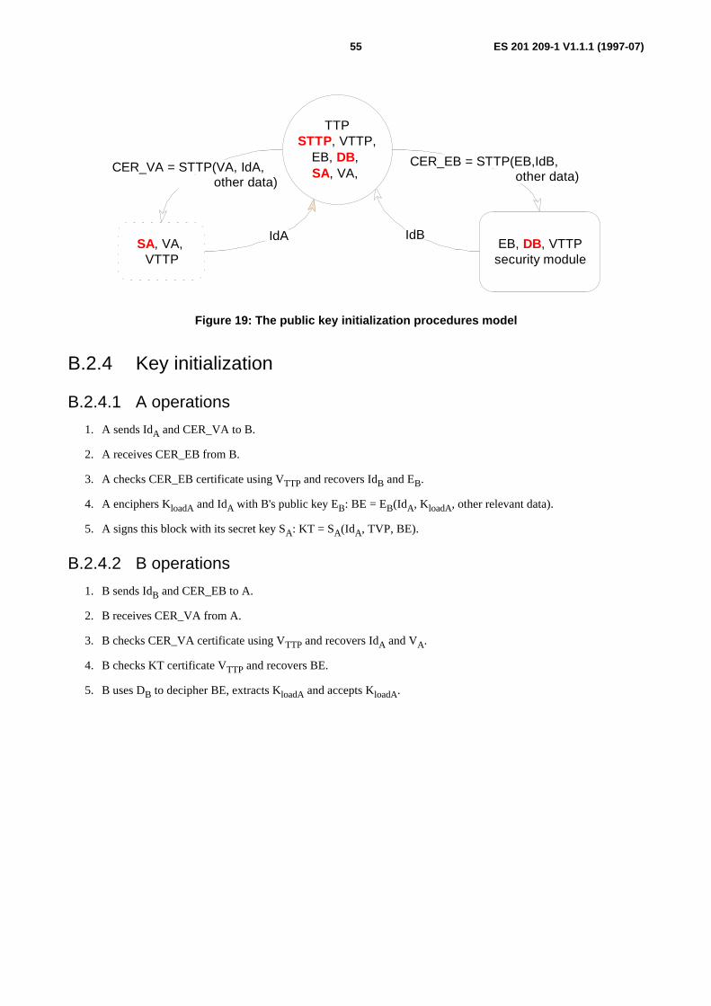
ES 201 209-1 V1.1.1 (1997-07)55
SA, VA, VTTP
TTP STTP, VTTP,
EB, DB, SA, VA,
EB, DB, VTTP security module
CER_VA = STTP(VA, IdA, other data)
IdA IdB
CER_EB = STTP(EB,IdB, other data)
Figure 19: The public key initialization procedures model
B.2.4 Key initialization
B.2.4.1 A operations
1. A sends IdA and CER_VA to B.
2. A receives CER_EB from B.
3. A checks CER_EB certificate using VTTP and recovers IdB and EB.
4. A enciphers KloadA and IdA with B's public key EB: BE = EB(IdA, KloadA, other relevant data).
5. A signs this block with its secret key SA: KT = SA(IdA, TVP, BE).
B.2.4.2 B operations
1. B sends IdB and CER_EB to A.
2. B receives CER_VA from A.
3. B checks CER_VA certificate using VTTP and recovers IdA and VA.
4. B checks KT certificate VTTP and recovers BE.
5. B uses DB to decipher BE, extracts KloadA and accepts KloadA.
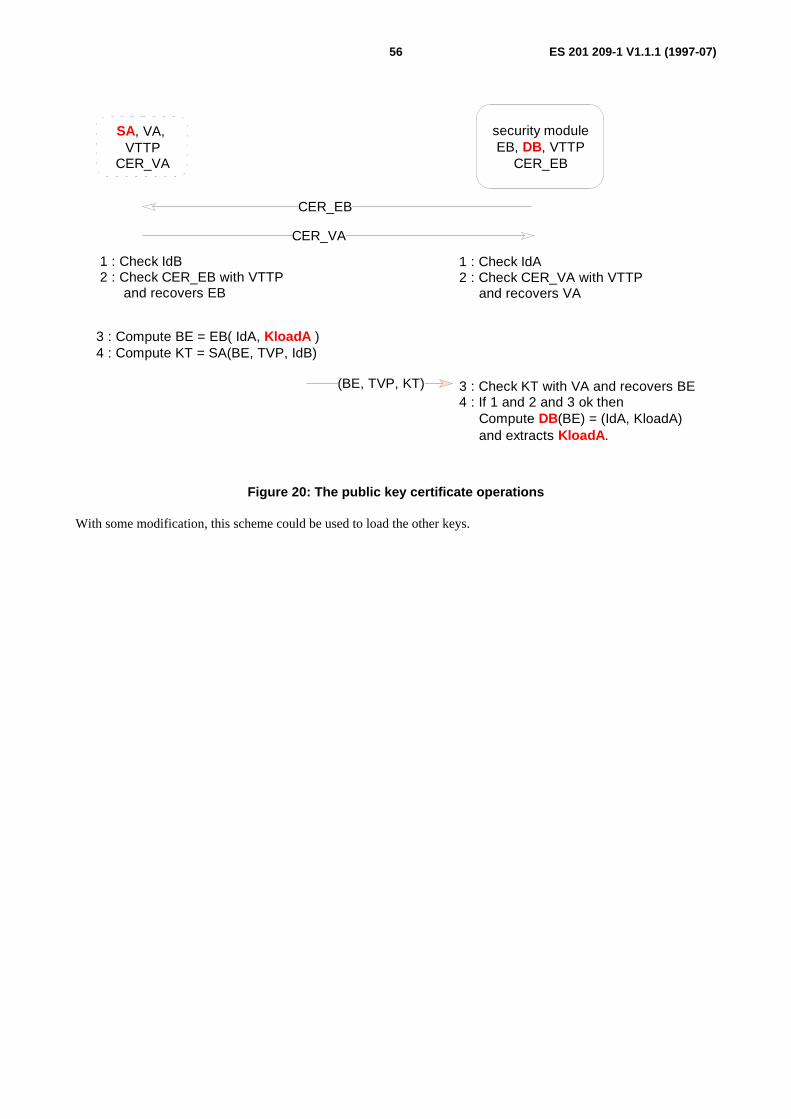
ES 201 209-1 V1.1.1 (1997-07)56
SA, VA, VTTP
CER_VA
security module EB, DB, VTTP
CER_EB
CER_EB
CER_VA
1 : Check IdB 2 : Check CER_EB with VTTP and recovers EB
(BE, TVP, KT) 3 : Check KT with VA and recovers BE 4 : If 1 and 2 and 3 ok then Compute DB(BE) = (IdA, KloadA) and extracts KloadA .
3 : Compute BE = EB( IdA, KloadA ) 4 : Compute KT = SA(BE, TVP, IdB)
1 : Check IdA 2 : Check CER_VA with VTTP and recovers VA
Figure 20: The public key certificate operations
With some modification, this scheme could be used to load the other keys.

ES 201 209-1 V1.1.1 (1997-07)57
Annex C (normative):UMC counter methodologies
C.1 IntroductionThe UMC counter shall operate on an abacus principle, with the counter area consisting of a number of rows of8 counter bits. Each row is assigned an octal value which is used in the counting process (dependent on the counterformat).
Value may be changed by programming bits totalling the required value. To enable a flexible counting mechanism, arow of bits may be erased (reloaded) when programming a bit (reloading bit) in the next higher counter stage. Thecounter mechanism shall be such that it shall not be possible to increase the number of available units.
A number of different possible counter formats exist (see annex D). It is not mandatory for all Security Modules andterminals to support all counter formats, but it is recommended that they should be designed to be flexible enough toadapt to the listed formats (e.g. different electrical values).
Factors that need to be considered for UMC counter operation may include:
1) Size and location of the counter:
Number of Bytes limited to 4 or 5
Address of the highest Byte of the counterAddress of the lowest Byte of the counter
2) Electrical value:
E: value associated with an erased bit
P: value associated with a programmed bit
3) Organization of the counting procedure: from the physical lower addresses to the higher (left hand) orfrom the physical higher addresses to the lower (right hand)
4) Use of each bit in the counter
R Used for reloading (or personalization) only - not available for counting, to be set to the value P
N Never used for counting - dedicated to application specific, test or personalization purposes
x Available for counting, these bits are the non R and N bits
C.2 Size and location of the counterThis document supports two abacus families, containing 4 or 5 Bytes.
The 5 Bytes abacus counter is located in UMC bits 64 to 103. Each counter stage consists of 1 Byte. The octal valueassociated with the abacus stages are 80, 81, 82, 83 and 84.
The 4 Bytes abacus counter is located in UMC bits 64 to 95. The abacus is organized in 3 stages: the lowest andintermediate stages consist of 1 Byte. The third stage consists of 2 Bytes. The octal value associated with the abacusstages are 80, 81 and 82.
The maximum value which can be stored in a 5-Byte counter may be up to 32 768 units depending on the use of specialbits.
The maximum value which can be stored in a 4-Byte counter may be up to 1 087 units depending on the use of specialbits.
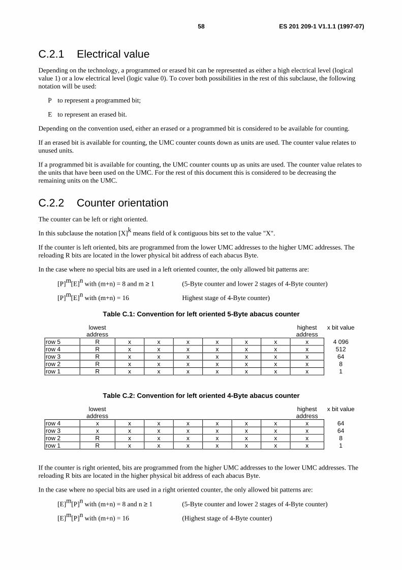
ES 201 209-1 V1.1.1 (1997-07)58
C.2.1 Electrical valueDepending on the technology, a programmed or erased bit can be represented as either a high electrical level (logicalvalue 1) or a low electrical level (logic value 0). To cover both possibilities in the rest of this subclause, the followingnotation will be used:
P to represent a programmed bit;
E to represent an erased bit.
Depending on the convention used, either an erased or a programmed bit is considered to be available for counting.
If an erased bit is available for counting, the UMC counter counts down as units are used. The counter value relates tounused units.
If a programmed bit is available for counting, the UMC counter counts up as units are used. The counter value relates tothe units that have been used on the UMC. For the rest of this document this is considered to be decreasing theremaining units on the UMC.
C.2.2 Counter orientationThe counter can be left or right oriented.
In this subclause the notation [X]k means field of k contiguous bits set to the value "X".
If the counter is left oriented, bits are programmed from the lower UMC addresses to the higher UMC addresses. Thereloading R bits are located in the lower physical bit address of each abacus Byte.
In the case where no special bits are used in a left oriented counter, the only allowed bit patterns are:
[P]m[E]n with (m+n) = 8 and m ≥ 1 (5-Byte counter and lower 2 stages of 4-Byte counter)
[P]m[E]n with (m+n) = 16 Highest stage of 4-Byte counter)
Table C.1: Convention for left oriented 5-Byte abacus counter
lowestaddress
highestaddress
x bit value
row 5 R x x x x x x x 4 096row 4 R x x x x x x x 512row 3 R x x x x x x x 64row 2 R x x x x x x x 8row 1 R x x x x x x x 1
Table C.2: Convention for left oriented 4-Byte abacus counter
lowestaddress
highestaddress
x bit value
row 4 x x x x x x x x 64row 3 x x x x x x x x 64row 2 R x x x x x x x 8row 1 R x x x x x x x 1
If the counter is right oriented, bits are programmed from the higher UMC addresses to the lower UMC addresses. Thereloading R bits are located in the higher physical bit address of each abacus Byte.
In the case where no special bits are used in a right oriented counter, the only allowed bit patterns are:
[E]m[P]n with (m+n) = 8 and n ≥ 1 (5-Byte counter and lower 2 stages of 4-Byte counter)
[E]m[P]n with (m+n) = 16 (Highest stage of 4-Byte counter)
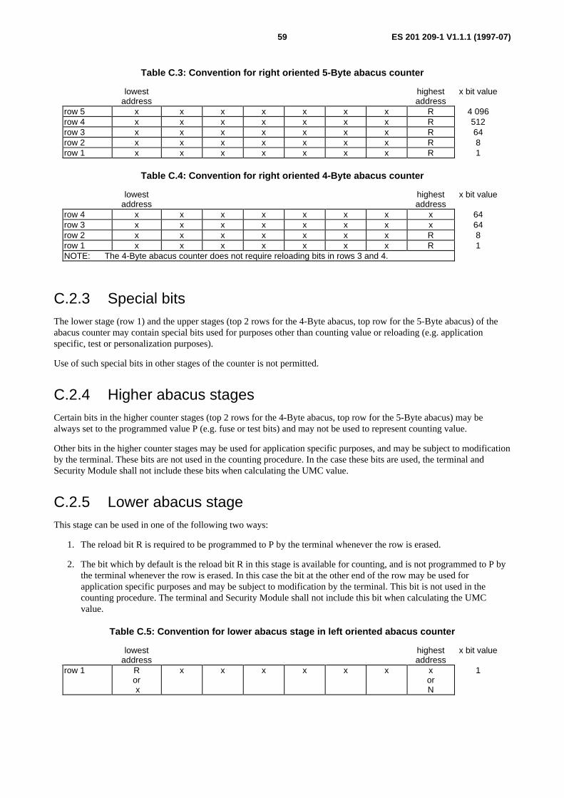
ES 201 209-1 V1.1.1 (1997-07)59
Table C.3: Convention for right oriented 5-Byte abacus counter
lowestaddress
highestaddress
x bit value
row 5 x x x x x x x R 4 096row 4 x x x x x x x R 512row 3 x x x x x x x R 64row 2 x x x x x x x R 8row 1 x x x x x x x R 1
Table C.4: Convention for right oriented 4-Byte abacus counter
lowestaddress
highestaddress
x bit value
row 4 x x x x x x x x 64row 3 x x x x x x x x 64row 2 x x x x x x x R 8row 1 x x x x x x x R 1NOTE: The 4-Byte abacus counter does not require reloading bits in rows 3 and 4.
C.2.3 Special bitsThe lower stage (row 1) and the upper stages (top 2 rows for the 4-Byte abacus, top row for the 5-Byte abacus) of theabacus counter may contain special bits used for purposes other than counting value or reloading (e.g. applicationspecific, test or personalization purposes).
Use of such special bits in other stages of the counter is not permitted.
C.2.4 Higher abacus stagesCertain bits in the higher counter stages (top 2 rows for the 4-Byte abacus, top row for the 5-Byte abacus) may bealways set to the programmed value P (e.g. fuse or test bits) and may not be used to represent counting value.
Other bits in the higher counter stages may be used for application specific purposes, and may be subject to modificationby the terminal. These bits are not used in the counting procedure. In the case these bits are used, the terminal andSecurity Module shall not include these bits when calculating the UMC value.
C.2.5 Lower abacus stageThis stage can be used in one of the following two ways:
1. The reload bit R is required to be programmed to P by the terminal whenever the row is erased.
2. The bit which by default is the reload bit R in this stage is available for counting, and is not programmed to P bythe terminal whenever the row is erased. In this case the bit at the other end of the row may be used forapplication specific purposes and may be subject to modification by the terminal. This bit is not used in thecounting procedure. The terminal and Security Module shall not include this bit when calculating the UMCvalue.
Table C.5: Convention for lower abacus stage in left oriented abacus counter
lowestaddress
highestaddress
x bit value
row 1 Ror x
x x x x x x xorN
1
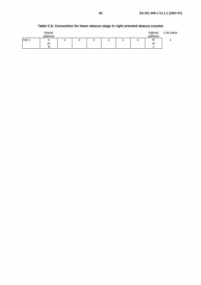
ES 201 209-1 V1.1.1 (1997-07)60
Table C.6: Convention for lower abacus stage in right oriented abacus counter
lowestaddress
highestaddress
x bit value
row 1 xor N
x x x x x x Rorx
1

ES 201 209-1 V1.1.1 (1997-07)61
Annex D (normative):Methods of operation for the counter on the UMC
D.1 IntroductionThis annex describes in detail the counting methods in current use. Card Issuers are encouraged to follow one of theseconventions when decrementing the counter as determined from the card data. Additionally, every reload cycle shall befollowed immediately by decrementing the left-hand bit of the reloaded row except in row 1 for methods A, D and E,and by decrementing the right-hand bit of the reloaded row except in row 1 for methods B and C.
D.2 Method AThe counter operates on the "abacus" principle. The counter is set to its required value by writing "0s" directly to therequired addresses in the counter area. The maximum value that can be stored is 16 383 units. The convention shown intable D.1 shall be followed, i.e. the "left-hand" bit in each row shall always be written to "0" and shall not be used forthe purpose of calculating the value in the counter.
Table D.1: Method A convention for decrementing value from the counter
lowestaddress
highestaddress
Bit value
row 5 P R x x x T T T 4 096row 4 R x x x x x x x 512row 3 R x x x x x x x 64row 2 R x x x x x x x 8row 1 N/U x x x x x x x 1
X = available for counting, i.e. erased by process of clearing the TLC.
P = personalization bit. Set to "0" in user configuration.
R = used for reloading only. Always set to "0". Not available for counting.
T = Reserved for test purposes. Never used for storage of value.
N/U = never used for storage of value. Always set to "0".
"1" = value stored (erased bit).
"0" = value destroyed (written bit).
The value storage bits in the counter area shall always be decremented from left to right, i.e. starting at the lowestaddress in a row and ending at the highest address in a row. Bits in row 5 have the highest value. They are equivalent to8 bits in row 4, and so on. Bits in row 1 have one unit of value each.
The terminal shall follow these conventions when decrementing the counter. Additionally, every reload cycle shall befollowed immediately by decrementing the left-hand bit of the reloaded row, so as to preserve the convention of notusing the left-hand bits for counting.

ES 201 209-1 V1.1.1 (1997-07)62
D.3 Method BThe counter operates on the "abacus" principle. The counter is set to its required value by writing "1s" directly to therequired addresses in the counter area. The maximum value that can be stored is 1 087 units. The convention shown intable D.2 shall be followed, i.e. the "right-hand" bit in row 1 and row 2 shall always be written to "1" and shall not beused for the purpose of calculating the value in the counter.
Table D.2: Method B convention for decrementing value from the counter
lowestaddress
highestaddress
Bit value
row 4 x x x x x x x x 64row 3 x x x x x x x x 64row 2 x x x x x x x R 8row 1 x x x x x x x R 1
X = available for counting, i.e. erased by process of clearing the TLC.
R = used for reloading only. Always set to "1". Not available for counting.
"0" = Erased bit.
"1" = Written bit.
The value storage bits in the counter area shall always be decremented from right to left, i.e. starting at the highestaddress in a row and ending at the lowest address in a row. Bits in row 4 and row 3 have the highest value. They areequivalent to 8 bits in row 2. Bits in row 2 are equivalent to 8 bits in row 1. Bits in row 1 have one unit of value each.
The terminal shall follow these conventions when decrementing the counter. Additionally, every reload cycle shall befollowed immediately by decrementing the right-hand bit of the reloaded row 1 and row 2, so as to preserve theconvention of not using these right-hand bits for counting.

ES 201 209-1 V1.1.1 (1997-07)63
D.4 Method CThe counter operates on the "abacus" principle. The counter is set to its required value by writing directly to the requiredaddresses in the counter area (value depending on the chip type). The maximum value that can be stored is 12 287 units.The convention shown in table D.3 shall be followed, i.e. the "right-hand" bit in row shall always be written (valuedepending on the chip type) and shall not be used for the purpose of calculating the value in the counter.
Table D.3: Method C convention for decrementing value from the counter
lowestaddress
highestaddress
Bit value
row 5 N/U N/U N/U N/U N/U x x R 4 096row 4 x x x x x x x R 512row 3 x x x x x x x R 64row 2 x x x x x x x R 8row 1 x x x x x x x R 1
X = available for counting, i.e. erased by process of clearing the TLC.
R = used for reloading only. Bit always written. Not available for counting.
N/U = never used for storage of value. Bit always written.
Written bit convention
"0" = erased bit then "1" = written bit Method C1
or
"1" = erased bit then "0" = written bit Method C2
The value storage bits in the counter area shall always be decremented from right to left, i.e. starting at the highestaddress in a row and ending at the lowest address in a row. Bits in row 5 have the highest value. They are equivalent to8 bits in row 4, and so on. Bits in row 1 have one unit of value each.
The terminal shall follow these conventions when decrementing the counter. Additionally, every reload cycle shall befollowed immediately by decrementing the left-hand bit of the reloaded row, so as to preserve the convention of notusing the right-hand bits for counting.

ES 201 209-1 V1.1.1 (1997-07)64
D.5 Method DThe counter operates on the "abacus" principle. The counter is set to its required value by writing "0s" directly to therequired addresses in the counter area. The maximum value that can be stored is 32 768 units. The convention shown intable D.4 shall be followed, i.e. the "left-hand" bit in each row shall always be written to "0" and shall not be used forthe purpose of calculating the value in the counter.
Table D.4: Method D convention for decrementing value from the counter
lowestaddress
highestaddress
Bit value
row 5 P R/x x x x x/T x/T x/T 4 096row 4 R x x x x x x x 512row 3 R x x x x x x x 64row 2 R x x x x x x x 8row 1 N/U/x x x x x x x x 1
X = available for counting, i.e. erased by process of clearing the TLC.
P = personalization bit. Set to "0" in user configuration.
R = used for reloading only. Always set to "0". Not available for counting.
x/T = May be used for test purposes, or for storage of value depending on the maximum value required.
N/U/x = Preferably not used for storage of value.
"1" = value stored (erased bit)
"0" = value destroyed (written bit) Method D1
or
"0" = value stored (erased bit)
"1" = value destroyed (written bit) Method D2
The value storage bits in the counter area shall always be decremented from left to right, i.e. starting at the lowestaddress in a row and ending at the highest address in a row. Bits in row 5 have the highest value. They are equivalent to8 bits in row 4, and so on. Bits in row 1 have one unit of value each.
The terminal shall follow these conventions when decrementing the counter. Additionally, every reload cycle shall befollowed immediately by decrementing the left-hand bit of the reloaded row, so as to preserve the convention of notusing the left-hand bits for counting. An exception to this convention can be made for row 1 allowing acceptance ofcards having this lowest bit with value stored.
NOTE: This method is a variant of Method A

ES 201 209-1 V1.1.1 (1997-07)65
D.6 Method EThe counter operates on the "abacus" principle. The counter is set to its required value by writing "0"s directly to therequired addresses in the counter area. The maximum value that can be stored is 21 064 units. The convention shown intable D.5 shall be followed, i.e. the "left-hand" bit in row 5 shall always be written to "0".
Table D.5: Method E convention for decrementing value from the counter
lowestaddress
highestaddress
row 5 P X X X X T T T 4 096row 4 R X X X X X X X 512row 3 R X X X X X X X 64row 2 R X X X X X X X 8row 1 X X X X X X X X 1
X = Available for counting, i.e. erased by process of clearing the TLC.
P = Personalization bit. Set to "0" in user configuration.
R = Used for reloading. Available for counting.
T = Reserved for test purposes.
"1"= Value stored (erased bit).
"0"= Value destroyed (written bit).
The value storage bits in the counter area shall always be decremented from left to right, i.e. starting at the lowestaddress in a row and ending at the highest address in a row.
Only in row 5 each erased bit is evaluated no matter whether the decrementing is done from left to right or vice versa.
Bits in row 5 have the highest value. They are equivalent to 8 bits in row 4, and so on. Bits in row 1 have one unit ofvalue each.
The terminal shall follow these conventions when decrementing the counter. Additionally, every reload cycle shall befollowed immediately by decrementing the left-hand bit of the reloaded row except in row 1.

ES 201 209-1 V1.1.1 (1997-07)66
Annex E (informative):Recommendations on items subject to bilateral agreementbetween Card Issuers and terminal/system operators
E.1 IntroductionThis document specifies minimum functionality to achieve interoperability of UMCs in different terminal operatorsterminals. It is necessary to take into account the existing situation which has prevented the adoption of a single solutionto some key aspects such as how the terminal can recognize the UMCs from different Card Issuers. Even if a singlesolution could be adopted it would still be necessary for each system operator to enter into a bilateral agreement with theCard Issuers that system operator decides to deal with. It is recommended that such bilateral agreements cover, at least,the following information:
E.2 Commercial matters1) Official contact personnel, their roles and their contact information.
2) The means used to transfer information, and network addresses and protocols to be used if electroniccommunication is used.
3) The procedures to be followed if MACs on counter values are asserted not to be correct.
4) Who keeps the counter values, and for how long.
5) The method of splitting value between the system/terminal operator and the Card Issuer.
6) The method by which the Card Issuer will pay the system/terminal operator.
7) Whether blacklists and/or whitelists will be used.
8) Whether call records need to be supplied back to the Card Issuer.
E.3 Technical matters9) The means of distinguishing UMCs from that Card Issuer from all other UMCs.
10) The monetary value of counter units, and how to distinguish if more than one is used by that Card Issuer.
11) The location of the counter on the card and its method of operation.
12) What data is included in the calculation of the card signature and the exact order of the data. Does the terminalapplication have to manipulate the data sent to the SM, or does the terminal application have to pass the carddata to the SM unchanged.
13) The UMC authentication algorithm used (or how this UMC authentication algorithm is going to be loaded ontoall the system operator's SMs or new SMs provided).
14) The number of UMC signature bits required to perform an increase of the SM counter.
15) The size and structure of the DF - EF suite required (or available) in the SMs.
16) Details of the number and function of the electrical contacts and the synchronous protocol used on the UMC toTerminal interface.
17) Use of any additional features such as Fixed Number Dialling or certificates.

ES 201 209-1 V1.1.1 (1997-07)67
E.4 Security matters18) Which method will be used for secure transfer of Card Issuer's keys into the terminal/system operator's Security
Modules.
19) Which security requirement specifications will apply to each of the secure components used in the system thatare relevant for interoperability, such as the SM and the secure device (if used). The parties also need toconsider their requirements for evaluating or proving that these security relevant components meet theirspecifications. The software (including firmware), hardware and processes all need to be considered.
The target for security needs to be specified (see annex A).
20) How the role of the TTP is to be fulfilled. The process for the management of keys needs to be specified andevaluated. This includes the Card Issuer, the TTP, and the system and terminal operators.
21) The nature of the proof and the procedures to be followed by the system operator to prove that the SM maskand all the downloaded software are authentic.

ES 201 209-1 V1.1.1 (1997-07)68
Annex F (informative):Fixed Number Dialling (FND)Pre-paid phone cards can have an optional Fixed Number Dialling (FND) facility. When this option is activated on acard, the card can only be used to pay for calls to the fixed number. This fixed number is stored on the card. Theterminal has to recognize that the card is for a fixed number only, to lock out the keypad and automatically dial thenumber.
This annex gives an example of how to implement Fixed Number Dialling.
At least 15 digit numbers need to be supported (see ITU-T Recommendation E.164 [19]). Country/geographic areacodes are allocated by the ITU and are 1, 2 or 3 digits long. The norm is 3 digits for a country code though manyEuropean countries have 2 digit codes at present (e.g. the UK is 44).
The terminal shall determine whether the card is Fixed Number Dialling. If it is then the terminal locks out the key padand executes the following procedure. The terminal first reads the national call flag.
If it is set it dials the number as on the card. This option is used for special national numbers (such as 0800 numbers). Awarning needs to be printed on the card that the card will only work in the stated country.
If the national call flag is not set, then the full international number is stored on the card (up to 15 digits). The terminaldetermines whether the country code part is for the country it is in (as far as the network is concerned) or whether aninternational call is required. It adds the appropriate prefix and dials either just the national number or the internationalnumber according to its determination.
Binary Coded Decimal encoding of a 15 digit number takes 7 Bytes plus 4 bits (60 bits). It is recommended that BinaryCoded Decimal encoding is used as straight binary encoding of the 15 digit decimal number requires 50 bits and thusdoes not save much memory on the card and is much harder for the terminal application to handle. It is recommendedthat the standard practice is adopted of setting unused digit positions to "F" in hex (i.e. "1111" in binary). Alternativelyvariable length encoding may be used with "F" in hex as the terminator. A full 15 digit number has no final value of "F".
For example assuming Binary Coded Decimal encoding on the card, Swiss telephone number (+41) 22 730 5994 wouldbe stored on the card as: 41227305994FFFF or 41227305994F.
A terminal in the UK would dial: 00 41227305994
A terminal in Switzerland would dial: 0 227305994
A terminal in France would dial: 19 41227305994
It is recommended that the data is laid out on the UMC as in table F.1.
Table F.1: Recommended layout for Fixed Number Dialling data
highest lowestrow 8 N1 N1 N1 N1 R R B Frow 7 N3 N3 N3 N3 N2 N2 N2 N2row 6 N5 N5 N5 N5 N4 N4 N4 N4row 5 N7 N7 N7 N7 N6 N6 N6 N6row 4 N9 N9 N9 N9 N8 N8 N8 N8row 3 N11 N11 N11 N11 N10 N10 N10 N10row 2 N13 N13 N13 N13 N12 N12 N12 N12row 1 N15 N15 N15 N15 N14 N14 N14 N14

ES 201 209-1 V1.1.1 (1997-07)69
F = Fixed Number Dialling flag.
B = National Call flag.
R = Reserved for future use.
Nn = Used to store the BCD encoded value of the n th digit of the number.
"1" = flag not set (bit not programmed).
"0" = flag set (bit programmed).
Using this example the N1 nibble would have the value "4", N2 the value "1", and so on.

ES 201 209-1 V1.1.1 (1997-07)70
Annex G (informative):Additional data elements
G.1 System operator/Card Issuer interfaceThe Card Issuer may provide system operators with information about valid cards in circulation (known as Whitelistinformation.
Whitelist ::= SEQUENCE OF
SEQUENCE {umc_issuer_id UMC_Issuer_Id OPTIONAL,
. . .,
SEQUENCE OF
SEQUENCE {CHOICE
{umc_batch_id UMC_Batch_Id,
individual_Ids SEQUENCE {umc_id_first UMC-id,
umc_id_last UMC-idOPTIONAL},
date_and_time_of_issue Date_and_Time OPTIONAL,
initial_value Value OPTIONAL,
initial_units Units OPTIONAL,
. . .
}
. . .
}
The Card Issuer may provide system operators with a response to invoice information sent by the system operator to theCard Issuer.
Invoice_info_response ::= SEQUENCE
{invoice_id Invoice_Id,
umc_issuer_id UMC_Issuer_Id OPTIONAL,
operator_id Operator_Id OPTIONAL,
. . .,
summary SEQUENCE {period_start_date_and_time Date_and_Time,
period_end_date_and_time Date_and_Time,
agreed_usage Units OPTIONAL,
agreed_value Value OPTIONAL,
. . . },
agreed_is_claimed BOOLEAN,
diagnostic_code Diagnostic_invoice_info_response OPTIONAL,
. . .,

ES 201 209-1 V1.1.1 (1997-07)71
disputed_detail SEQUENCE OF
SEQUENCE {sm_id SM-id,
umc_type UMC-Type,
date_and_time_of_first_entry Date_and_Time OPTIONAL,
date_and_time_of_last_entry Date_and_Time OPTIONAL,
usage Units OPTIONAL,
value_claimed Value,
mac MAC,
. . . } OPTIONAL
. . . }
System operators may also regularly provide each Card Issuer, with which they have an agreement, call recordinformation for either each use of an UMC, or first and last use of an UMC.
Call_record_info ::= SEQUENCE {umc_issuer_id UMC_Issuer_Id OPTIONAL,
operator_id Operator_Id OPTIONAL,
. . .,
summary SEQUENCE
{period_start_date_and_time Date_and_Time,
period_end_date_and_time Date_and_Time,
sm_id SM-id,
site_tel_no Telephone_number,
. . .
},
detail SEQUENCE OF Call_record,
. . .
}
Call_record ::= SEQUENCE {umc_type UMC-Type,
umc_id UMC-Id,
date_and_time_of_start Date_and_Time OPTIONAL,
date_and_time_of_finish Date_and_Time OPTIONAL,
initial_value Units OPTIONAL,
final_value Units OPTIONAL,
first_use BOOLEAN OPTIONAL,
no_value_left BOOLEAN OPTIONAL,
expiry_date Date OPTIONAL,
. . .
}

ES 201 209-1 V1.1.1 (1997-07)72
Annex H (informative):MAC generation: an example
H.1 IntroductionThis example for MAC generation uses the DES algorithm. However, the generation of MACs is not limited to thisalgorithm. Other algorithms such as TESA-7 could be used.
For each Card Issuer, there should be a key in the SM for MAC generation:
KMAC
With this key a MAC is calculated for every counter together with some additional data. This data, secured with theMAC, is sent regularly to the background system, where it can be stored, or sent further to the co-operating partner. Theco-operating partner can check the integrity of the counters by inspection of the MACs.
An example using this data might consist of:
(Random, Path of the SID (Security Module ID), SID, Path of the counter, Counter),
where the path information is a constant value.
The MAC is calculated by DES enciphering in CBC-Mode, where the last 64-bit enciphering block is used as MAC.Thus for the MAC calculation a 64-bit DES-key is applied.
H.2 Detailed description of the dataBefore the MAC generation is started, an 8-Byte random is chosen, which is used as initialization value (IV). The datato be MACed consists of 5 blocks with 8-Byte each:
Block status(viewed fromCard Issuer)
content
1. constant path of EFID 4 Byte, INS, P1, P2, Le of READ Binary (1 Byte each)
2. dynamic first 8-Byte of the Security Module ID (SID)
3. dynamic 9th and 10th Byte of the SID padded with 6 Byte zeros
4. constant path of EFcounter 4 Byte, INS, P1, P2, Le of READ Record (1 Byte each)
5. dynamic counter (4 Byte) padded with 4 Byte zeros

ES 201 209-1 V1.1.1 (1997-07)73
H.3 Detailed description of the algorithmLet b1 to b5 be the 5 data blocks defined above and IV the 8-Byte random value. Further define y := DES(K, x) to bethe 8-Byte cipher text, received by a DES encryption of the 8-Byte plain text x with the DES-Key K. Let ⊕ define theXOR operation. Then the MAC is calculated as follows:
c1 := DES[KMAC](IV ⊕ b1)
ci := DES[KMAC](c(i-1) ⊕ bi) for i = 2, ... ,5
where the MAC is chosen to be:
MAC(IV, b1, ... , b5) := c5.
Applying such a scheme, the first 8-Byte block of the input data could be manipulated in principle. But the first datablock is constant, so there is nothing to be reached in doing so, and the manipulation can be detected, when the constantvalue is known.

ES 201 209-1 V1.1.1 (1997-07)74
Annex J (informative):Bibliography
J.1 IntroductionThis annex contains references to relevant background material. Whilst they are not referred to directly in the text theyhave been retained in this annex because readers of this document may find them useful background reading on theoperational use of smart or memory cards in terminal systems.
J.2 Informative references- EN 726-1 (1994): "Identification Card Systems - Telecommunication Integrated Circuit Cards and Terminals -
Part 1: System Overview".
- EN 726-2 (1995): "Identification Card Systems - Telecommunication Integrated Circuit Cards and Terminals -Part 2: Security framework".
- EN 726-4 (1994): "Identification Card Systems - Telecommunication Integrated Circuit Cards and Terminals -Part 4: Application independent card related terminal requirements".
- EN 726-5: "Identification Card Systems - Telecommunication Integrated Circuit Cards and Terminals - Part 5:Payment methods".
- EN 726-6 (1995): "Identification Card Systems - Telecommunication Integrated Circuit Cards and Terminals -Part 6: Telecommunication features".
- EN 1038: "Identification card systems - Telecommunications applications - Integrated circuit(s) cardpayphone".
- ISO/IEC 7812-1: "Identification cards - Numbering system and registration procedure for issuer identifiers -Part 1: ".
- ISO/IEC 7812-2: "Identification cards - Numbering system and registration procedure for issuer identifiers -Part 2: ".
- ISO 10202-4: "Financial transaction cards - Security architectures of financial transaction systems usingIntegrated Circuit Cards - Part 4: Secure Application Module".
- ISO 10202-5: "Financial transaction cards - Security architectures of financial transaction systems usingIntegrated Circuit Cards - Part 5: Use of algorithms".
- ISO/IEC JTC1/SC27 N 1082: "Guidelines for the use and management of Trusted Third Parties; Part 1:General overview".
- ETSI TCR-TR 028 (July 1995): "Network Aspects (NA); Security Techniques Advisory Group (STAG);Glossary of security terminology".

ES 201 209-1 V1.1.1 (1997-07)75
History
Document history
V1.1.1 May 1997 Membership Approval Procedure MAP 9729: 1997-05-20 to 1997-07-18
V1.1.1 July 1997 Publication
ISBN 2-7437-1638-XDépôt légal : Juillet 1997