:ery o urrci - americanradiohistory.com · up in. x t lin. ideal tor super radiogram, complete kit,...
TRANSCRIPT
o
urrci Vol. 24. No. 508.
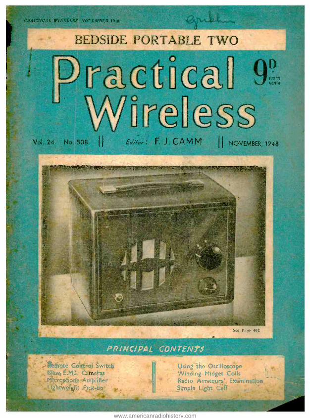
PORTABI TWO
tunk C :ERY
MCNTµ
ti .i . C A M (vl H NOVEMBER, 1948
2
See Page 462
PR /NC /PA! CONTENTS
' . itt lit) gxe Control Switcb 6TeN¿, Ë.M.I. Cameras
. : Micróptïorfe Amplifier `" .SLightwefght Pick-up
Using the Oscilloscope Winding Midget Coils Radio Amateurs' Examination Simple Light Cell _
www.americanradiohistory.com
-PREMIER- RADIO CO.
MCi.tRi5 & CO , RADIO, LTD. Ai 1 tt t t ! i' I i: 1: 1 , f. t 1 . --7-valve wills rectifi, e t i I
` lei 900-2,100 metres. Pit k tt i.
ition t waves hangs, sitit It uses 0K7 IR,F,I. 6K8 keen. hangers. 8X7 tl.F' 1 647 (2nd Det A.V.C. and 1st L.P.,. (3,(i
i Phase 'Merrier?, 0 -25X6 in Push -Pull. Output. Transform, inatebes 3 or 15 ohm, negative feedbar.k, Illuminated Glass Dial. UP in. x t lin. Ideal tor Super Radiogram, Complete kit, with valves. £1i3ä 10. in'. P.T. ; Wired and Petted, £15'Oó. Inc. F.T. Reemi mended t,on,d,Vegitkee. -10018 Super 0.12. 85 -. .1,11. -WAVE sí-1'}; ÌI :1 K11'. .1 Rit of Parts to build a
(i-valve (plus reel iller i redeiver, covering 16-50 metres. Medium and long -tvAve bands. Valve like -vp : 8K8. 6X7, 60,17. 6J7. two 25.45 in push -pull. Metal rectifiers are incorporated for H.T. supply, Output impedance is for 3 ami la ohms. The latest Wearite coil park inrorporatin;: iron dust coils is aced, making construction and alignment extremely simple. A pitk -up position on the waverhange switch anti pick -up terminale is Provided. A rnmplete kit, including valves, but Without smatter or cabinet. Chassis size, 141n. s (An. Overall height.
Pri'e £10 16 6 .oih Port hase Tat _,sis £121000. ` 't t pcakers are the CI
R -tcatl P.M. 4' Inc shpt- latìve rcptv.r. r f' ` ',. f, 15 0.
Ci 5, SI I it tit i,!'I. 16 to 2.000 r - ad. 2 Maeda.
I. lensetr, re.. sole, £6100.
NI tt 1í!)q ti tlrl.! I 1.1:.1. It NMI. tu I, with (lunes
.1ru.uun 700-2.000 n
w
is retit' ..
,''hast, Ta--.. tcN- 1948 311IU.1
(aas> ì i115tfül'tin,l- .. 10O=507 ;
I a'PI:1:I!r 1 l' ,. .. t .. . I
"alt'es DI II, 'OrL ì r It!If s., ne'idt- ?PO to 250V. ,k,(. i,i' A.C. D.C. naine. State
£850, inciudine
I I I l tt I X i n brown bakelite. Can le
fidget Kits at 25 -. ''LI4' .SEASON'S LIST IS 1\-()IF READY
['(rase send stamp foi.- copy. nt Ile\ vie \T sI i:lI t_, 311.1\S 1'N:1A1FORì1 F:Ft ti.
scie main,. These are a.
0l -B-5on o. )51 m a. 4 v. 2.5 a 4 v. 1 a., 4 v. 5 a., 6lin, 35 t lin, x )tin.
865 -0 -865 ;..500 m a. Tapped at 660 v. and 760 v 4 v. 75 - 3 a.. 4 v. 4 a.. loin. x 711in, x Sin. L.T. is separate trans. on base plate.
40 v. 3 a 101 v. 1' a. (auto wound), 4in - it 4in. x Sin. 21 -
650- 1f-6(Á v. 150 n a. and 1,000 v. at 30 m'a., Olin. is 40 -
Pitl. !( O';tn. 18 v. 2 a., tapped at 32 t-, 34 v., 36 v.. 41in. t 4in. x sin. 15 -
1900 -0 -15013 v.120 ni a., 4 v.2-3 a.. 4 v. 2 -3 a.. 7 i n. x 5i n. 55 Bin. L.T. trans. is separate on base plate.
,00 -0 -500 v. 1711 in a.. i v. 4 a., but. a din. s lin. 35 -
rv.20a.,7'in.a41in.a4lin. 25 -
10 v. 5 a.. 10 v. 5 a . , 10 v. 5 tt., Gin. a dl in. a 4lin. 3 5 -
t î l i , l v . l a.. 2 v. 2 a.. Sin. s 4in, s filin. 35- Auto 50 v., 100 v., 150 v., 230 v., 1('0 w., 4 in. s Nin. '12 6
21iu. Output trans. ratios 4:3,5 -1 and 61.5 -1 set's.. 2.1 ohms 45 -
and 4.2 ohms, 8'.in. x Hilt x (t1in., wt. 211 lbs. 37e -0 -275 v. 120 m a., 5 v. 2 a., 0.:3 v. 2.5 a., 6.:3 v..3 a. 20 -
T. îin, a bin. An ideal transformer peen ..
sling or welding. 2h-. lsne'hs of steel tube
na' - 'lie lent aerial, 3 6 e.,
a,.,.
1 -01 Ilsii 1011 1. l'.1i.. "
hilt. P.M., 2 -3 ohms ... ... ... ... ... ... l6 6
sin. P.M.. 2 -3 ohm, ... ... .. ..- ... 17 6 6
..`;,i ... ... ,..
:11'1 1! i-':. Tim - 25
\ti.S t. ,
ALL POST ORDE -' - 0 JUBILEE WORKS, 167, LOWER
GLAPTON ROAD, LONDON, ES. 'Phone : Amherst 4723
ALL CALLERS TO 169, FLEET STREET, LONDON, E.C.4.
'Phone : Central 2833
!UM LOCTAL VALVEHOLDERS FOR LOC -K -IN TYPE VALVES E81.21, ECH21, 7A7E, 788, etc.
A double -plate laminated valveholder designed with 8 special sockets and
centre spigot socket meeting the requirements of the ß8G and B8B
range of Loctal Valves.
THE CENERAL ACCESSORIES CO. LTD.
21 Bruton Street, London, W.1 Tel. MAYfair 5543
FOREMOST IN VALVEHOLDER DESIGN
VALLANC.E'S SPECIAL OFFERS
MIDGET MAINS TRANSFORMER, TYPE MTIM1.- A small upright -type transformer, suitable for signal generators, V.F.O.s, midget receivers and many other applications where -ize is the limiting factor. Primary. 20012301250 volts, with electrostatic screen. Secondaries. 260 -0.260 volts, .60 mli. 0 -4 -5 volts at 2 amps. 0.6.3 volts at 3 amps. Dimensions. 2'in. x tin. x Shin. high with four mounting feet. New and improved design Price 2316.
CRYSTAL DETECTORS. Cat's- whisker type, less crystal, 21 -. Semi- permanent type with two crystals, 216. Packets of one crystal with whisker, 6d. ,
HEADPHONES. -An extremely sensitive pair of lightweight 'phones of American manufacture. ideal for crystal sets and sets with low impedance output, but can be matched to high impedance circuits with a 4 : I ratio (approx.) transformer. Complete with rubber- cushioned ear pads, leather headbands, cord and jack plug. New cond.tion, 319 per pair, plus II- postage and packing
ENAMELLED COPPER WIRE.-4 oz. reels. 18 and 20 S.W.G., 118 ; 22 S.W.G., 21- ; 24 S.W.G., 213 ; 26 S.W.G., 215 ;
216 ; 30 SW.G., 218 ; 32 S,W,G.,. 2fí0 ; 36 S.W.G., 315 ; 35 S.W.G., 31 -; 40 S.W.G., 413.
BAKELITE SHEET.-/ Ain. thick. Sizes l2in. x 8in., SII ; 10in. x (Sin., 413 ; 1Oin. x 6in., 315 ; 8in. x 6in., 2110 ; 6in. x 6in., 213 ;
6in. x -4in., 118.
CARBON THROAT MIKES -A lightweight, compact and sensitive unit, complete with elastic strap, cord._ and two -pin plug. American manufacture, brand new, 115.
SPEEDY POSTAL SERVICE, C.W.O. or C.O.D. When ordering C.W.O., please inclssde 11- (minimum charge)
for postage and pecking.
VALLANCE & DAVISON, LTD. !44, Briggate, Leeds I. 'Phone : 29428,9.
Staff call signs :- G21-41-4V. GBSX. (17ARn. G3CML.
i
i
www.americanradiohistory.com
lovember, 1948 PRACTICAL WIRELESS
INSTRUMENT Co., 244, HARROW RD., LONDON, W.2. Cun.05o8 MAINS TRANS. Drop - through type. Primary 200 250 volts, Secondary 350 -0.350 80 mA, 5 volts 2 amps., 6.3 volt::, 3 amps. Post paid Same TRANS. as above, but with 4 -volt tapping instead of 6.3. Post paid £1 Same as above, but Stand -up type with 6.3 or 4 volt tapping. Post paid £1 EX- R.A.F. AMPLIFIER 1134. Ideal for use with a microphone, or can be used as an amplifier without modification. Complete with wooden transit case.
17/6 Post. free NUTS, BOLTS, WASHERS. Small sizes for model making. 3 gross assorted. SCREENED FLEX. Suitable for mikes, 100ft.
1 24 VOLT MOTORS. Can be run off lower voltages but at reduced speeds. Post free.
£1
7/6
MULTIRANGE TEST T METER. 17 ranges ACIDC volts, milliamp and ohms. 1000 ohms per volt.
£7 Brand new TWIN WIRE for internal wiring, lighting points, etc. Minimum quantity I2yds. 5/-
ALL TAYLOR METERS ON H.P. AVO's in Stock. I 155's with Power Pack, Speaker and Cabinet
£18 ready for A.C. mains LOW RESISTANCE PHONES. Lightweight with plue-in Jack 7/6 BC348, 28 volt.
£18 /l U/- Plus 101- packing
Fitted internal AC Power Pack. 200 -250 volts. Plus £22/10/- lot- packing. 2 ¡in. FLUSH MOUNTING MILLIAMMETER. Moving coil, Bakelite case, 0.1
6 FSD.Brand new, Post free 13 2:in. FLUSH MOVING IRON AMMETER 0 -25
7/6 Post free 12 ASSORTED MAGNETIC RELAYS for experimental purposes. Post free
PHOTO -ELECTRIC CELL. Dozens of applications, e.g., burglar alarms, counting,
14/6 door -opening. etc. Light Operated Kit for above cell. 57 /E NO C.O.D. ORDERS UNDER £ l .
Write to Dept. ''R
INSTRUMENT CO. 244 HARROW ROAD,
LONDON, W.2
OLIVER PELL CONTROL LTD 7(pb n. - WOOLW.CH 1422 CAMBRIDGE ROW WOOLWICH S E18
\ \ \\ \l` t\ \\\\9ï \ :9 \ 6
POWER r. .:.... ..\\\\\ -`\\\ \\ \ ;
'`\\\V.\\\\\ .. r:\\\\ ..... \
.
\\ \ \ ". \ ' .ù : \s<:: \\ ` ' T'-'. ;: x \\. !.. \.\. \ . \\. \. ö. \\' \\\ \. .ä
- ` .,\---4 ..... _.\\\\\\\\\ \\a .., r.. A,......,, , ..,, .... , .. . . . . . .. \. a. *
441
iL 011a
i
010 P11 Eß1ESl I
R A
a5 dok w' P4E
For clean, crisp reception a silent source of power is essential, Pearls Radio Batteries give silent power.
HOLSUN BATTERIES LIMITED 137 Victoria Street
London, SVV-I
www.americanradiohistory.com

r
442 PRACTICAL WIRELESS
D.C. Voltage A.C. Voltage C -75 millivolts 0 -5 volts C -5 volts 0 -25 0 -25 0-100 0-100 0 -250 0 -250 0 -500 0 -500
Resistance D.C. Current 0- 20,000 ohms
0 -2.5 milliamps 0- 100,000 0-5 0- 500,000 0 -25 0 -2 megohms 0 -100 0-500 0 -10 GUARANTEE: The registered Trade Mark " Avo " is in itself a guarantee of high accuracy and superi- ority of design and craftsmanship. Every new AvoMinor is guaranteed by the Manufacturers against the remote possibility of defective materials or workmanship.
November, 1948
/
_9-ac/607L EILEC7112ICAIL1
LE51TIVG YIVSTRiJIi/EtiT
A dependably accurate instrument for testing and fault location is indispensable to the amateur who builds or services his own set. Stocks are now available of these two famous " Avo " Instruments. If you have any difficulty in obtaining one locally, please send us the name and address of your nearest Radio Dealer.
The UNIVERSAL AVOMINOR (as illustrated) is a highly accurate moving -coil instrument, conveniently compact, for measuring A.C. and D.C. voltage, D.C. current, and also resistance; 22 ranges of readings on a 3 -inch scale. Total resistance 200,000 ohms.
Size : Q }ins. x gpins. x ¡bins. Complete with leads, inter - Nett weight : ¡8 ozs. changeable prods and croco-
dile clips, and instruction Price : book.
The D.C. AVOMINOR is a 21-inch moving coil meter providing 14 ranges of readings of D.C. voltage, current and resistance up to 600 volts, 120 milliamps, and 3 megohms respectively. Total resistance soo,000 ohms.
Size : Qeins. x Spins. x ¡bins. Nett weight : ¡2 ozs.
Sole Proprietors and Manufacturers AUTOMATIC COIL WINDER & ELECTRICAL EQUIPMENT CO., LTD.
Winder House, Douglas Street, London, S.W.I. 'Phone : VI Ctorio 3404 -9
Complete as above.
Price : £4:4:0
There is something fascinating about the'sound of silver clinking into a bag -and it is the true `. reproduction of the " noises -off " that mean so
Omuch when listening to a favourite programme - y Home, Light or Third. It has taken us 18 years to achieve such realism ... it's yours to -day. A range e of three- extension cabinet speakers is in the dealers'
shops already, " Monobolt " speaker chassis in four
O sizes are there, too, you can hear them now. High fidelity
pickups and " Wafer " speakers are well on the way.
S that A postcard will bring full details.
MODEL 13X105. One of the new range of Truvox Extension Cabinet Speakers. This model incorporates 10in. Monobolt chassis, volume control recessed in side. Beautiful Walnut cabinet with contrasting chamfers and fret motif in Maple. List Price, £S 10s.
Troyes Engineering Co., Ltd., Truvox House. Exhibition Grounds, Wembley, Middx.
I X35A
www.americanradiohistory.com

November, 1948 PRACTICAL WIRELESS 443
PracficA Wórg (and PRACTICAL TELEVISION
ifat f.J.CAMM EVERY MONTH
VOL. XXIV. No. 508 NOVEMBER, 1943
COMMENTS OF THE MONTH
16th YEAR OF ISSUE
BY THE EDITOR
Government Television Policy TORD TREFGARNE'S statement of the
Government policy in relation to television is a triumph for the radio industry. Lord
Trefgarne is the chairman of the Television Advisory Committee, and in the course of their investigations they have examined every television system and they reached the conclusion that, notwithstanding all that is being done in this country, as well as abroad, the existing British system is the best and they do not recommend any change.
The Postmaster -General has authorised prefatory work on further extensions using this system, and he proposes that the number of lines should not be altered for some years to come.
He thinks that the improvements in the quality of the picture resulting from alternative systems are too slight to warrant change which would render, in any case, all British television receivers obsolete. Moreover, any change at this juncture would prejudice more substantial improvements later, such as colour television.
Those who, therefore, have refrained from pur- chasing a television receiver because they suspected that they might rapidly go out of date have (àon'ernment assurance that the present system will c.ultinue for many years to come. The 405 -line ssteni is being adopted for the Midlands station and is proposed for other British stations. It is likely that the Midlands station will be opened in the autumn of 1940. This station, although working on the same basic system as that at Alexandra Palme, will incorporate various improvements. The power of the vision trans- mitter will be twice as great, and tlu)t of the sound transmitter four times as great. The frequencies for vision and sound will be in the neighbourhood of 60 megacycles per second. The Post Office is providing alternative radio and cable links to bring the pro- grammes from London to Hill Village, Sutton Coldiield, where the new station will be located. ft is intended that when the Sutton Goldfield station is com- pleted, the next will be erected itt the North of England.
The Radio Industry Council, in welcoming the Postmaster -
General's statement, states that the chief requirements for tele- vision - development are : (aj
picture quality (it has been proved by recent television broadcasts from the studio and outside that excellent clarity, definition and general quality of the picture are ensured by the British 405 -line system ; (b) cheapness of sets (the British system is the best engineering compromise between maximum picture quality and minimum cost of production.
It is pointed out that the economic development of television services in Europe will depend upon the manufacture of a cheap receiver ; the establish- ment of the greatest possible service area for each transmitter ; and the provision at low cost of links by cable and radio between one station and another so that programme costs -the most expensive part of a television service -can be shared between one centre and another.
Adoption of the British system as the standard in Europe would meet all these requirements. The countries adopting it would have the additional advantages of linking themselves with a highly - developed source of programmes and of benefiting by Britain's unique experience of television in the past. They would be in a position to enjoy the technical improvements which are certain to be macle in the British system in the future without fundamental alteration of the system ; and equally, in due tinte, the advantages of any major develop-
ments which may be made in years to come.
The Radio Industry Council intends to bring these points to the attention of all concerned. In September it gave its first television demonstration abroad. This was in the British Exhibition at Copenhagen where, with the collaboration of the Danish State Broadcasting and the B.B.C., outside scenes and studio burns were televised by all- British equipment and the results seen by 10,000 people a day in British receivers in the Nimb Restaurant in the Tivoli Gardens.
Great advances have been made in British television technique as a result of the war and the use of television tubes ill connection with radio location and the land- ing of aircraft. When several stations are operating and the demand for receivers is corre- spondingly increased, technical advances will be more rapid.
..... ...........: ............,...,....._- ......s Editorial and Advertisement Offices :
" Practical Wireless," George Nunes. Ltd., Tower House, Southampton Street, Strand,
W.C.2. 'Phone : Temple Bar 4363. Telegrams : Newnes, Rand, London.
Registered at the G.P.O: for transmission by Canadian Magazine Post.
The Editor Will be pleased to consider s' articles of a practical nature suitable for publication in " Practical Wireless." Such articles should be written on one side of the paper only. and should con- ; tai» the name and address of the sender. ; Whilst the Editor does not hold himself j responsible for manuscripts. every effort will be made to return them ifa stamped j and addressed envelope is enclosed. j All correspondence intended for the j Editor should be addressed : The Editor. j " Practical Wireless," George Newnes. j Ltd.. Tower House. Southampton j Street. Strand. W.C.2,
Owing to the rapid progress in the j design of wireless apparatus and to our j efforts to keep our readers in touch ' with the latest developments, we give 3 no warranty that apparatus described I in our columns is not the Subject of j letters patent. j
Copyright in all drawings. photo- i graphs and articles published in j
Practical Wireless" is specifically j reserved throughout the countries j signatory to the Berne Convention and j the U.S.A. Reproductions or imitations i of any of these are therefore expressly j forbidden. ' Practical Wireless " t incorporates " Amateur Wireless."
www.americanradiohistory.com
444 PRACTICAL WIRELESS November, 1948
ROUND THE
Broadcast Receiving Licences THE following statement shows the approximate
numbers of licences issued during the year ended July 31st, 1948.
Region London Postal.. Home Counties Midland.. .. North Eastern .. North Western South Western.. Welsh and Border
Total England and Wales Scotland Northern Ireland ..
Grand Total .
Number 2,104,000 1,478,000 1,609,000 1,743,000 1,473,000
983,000 653,000
10,043,000 1,064,000
186,000
11,293,000
The above number includes 58,250 television licences, an increase of 3,400 over the previous month.
Prosecutions in July for operating wireless receiving apparatus without a licence numbered 440.
They Have a Word For It
E. K. COLE announce that henceforth their EKCO television receivers will be known as
EKCOVISION. The company has been consider- ing the idea for some time and the new telescopic word will, they believe, be convenient to both trade and public, being a much less unwieldy way of describing their sets. There is evident general interest in the word " television " at present. The Daily Express has even run a campaign to find a new word. Ekco's decision is, therefore, opportune . and in spite of many ingenious possibilities in word -making they believe they are right in retaining " vision " as the root idea.
Radio -export Target Exceeded RDIAO exports exceeded the target and reached
new records during the first half of 1948, according to an analysis- issued by the Radio Industry Council recently -of the official Customs and Excise figures.
The total value for six months was £6,297,130, an average of £1,049,521 per month as compared with a target of £1,000,000 a month. February was the only month when the target was not exceeded.
Olympic Torches IT may now be revealed that the main contractors
for the Olympic Torches were E.M.I., Ltd., at Hayes. These torches, numbering over 1,500, were used to carry the flame from Mount Olympus, in Greece, to Wembley Stadium, for tho 1948 Olympiad.
60F WIRELESS
First Brass Band Televised MORRIS MOTORS, LTD., WORKS BAND was
the first British brass band ever to be televised when they took part in the Television Fête at Alexandra Palace recently.
Overseas Economic Surveys TWO further Overseas Economic Surveys in the
series published for the Export Promotions Department of the Board of Trade by H.M. Stationery Office, are now available. " Iran (Persia)," price ls., and " United States of America," price 3s. 6d.
Television Cameras in Downing Street
DURING the period, starting October .11th, when the Commonwealth Prime Ministers assemble
in London, the B.B.C. is hoping to be able to televise. a part of one of the meetings. This will be the first occasion on which television cameras have been installed in Downing Street.
Interference -free Plug ASPARKING plug is now in production in the
U.S.A. which incorporates a built -in 10,000 ohm .resistor so that the car to which it is fitted will not be so liable to cause interferencé on F.M. and television frequencies. It is also claimed that the incorporation of this resistor reduces engine misfiring and lengthens the life of cylinder walls, rings and pistons.
Eire Police Radio
IVI ARCONI'S have received an order for twin - diversity radio for the police in Eire. A main
transmitter (reported to he due for installation just outside Dublin), eight H.Q. sets, 15 mobile sets and 14 receivers are included in the order.
New Norwich Station
WORK has commenced on the construction of a new B.B.C. transmitter near Norwich. With
a rating of 5 kW. it is intended ultimately to replace the present 1 kW. station, and will radiato the Midland home service on 296.2 metres. A directional aerial system is to be used, consisting of two mast radiators each 126ft. in height.
New B.B.C. Wavelengths CERTAIN changes will be made in March next
to the wavelengths of a number of stations as a- result of the new plan agreed in Copenhagen. Droitwich, radiating the Light programme on 1,500 metres, will use 400 kW. and remains on its frequency. The second Droitwich transmitter will use 120 kW. on 464 metres. The London wavelength will be changed to 330 metres and will not share. this wavelength with any other station.
www.americanradiohistory.com

November, 1948 PRACTICAL WIRELESS 445
Amateur Frequency Band THE Postmaster General announces that, as
from October 1st, 1948, holders of amateur wireless station licences may use telegraphy and telephony on any frequency between 420 and 401) Mc;'s, with power not exceeding 10' watts, subject to the general conditions of their licences and subject to no- interference being caused with the working of other services.
I.P.R.E. Start New South -west Section FOLLOWING quickly upon the formation of a
Birmingham Section, the Institute of Practical Radio Engineers has now successfully formed a South -west Section. The inaugu- ration meeting was held in Newton Abbot on September 1st.
Mr. R. P. B. Williams was elected chairman and Mr. F. C. Roberts, secretary. Their supporting com- mittee will consist of Messrs. F. - J. Bennett, D. H. Gibson. E. D. Knapp, F. F. McClean and W. H. Terry.
111r. J. F. Tomlin, the president of the Institute, announced that dito to the pending " Better Listening " campaign, it had been decided to postpone the proposed 1.1'.11.E. test equipment and ser- vicing exhibition until early in 1949.
Stockholm Show A PRIVATE exhibition of British
radio components and asso- ciated equipment will be given in Stockholm from October 18th to 22nd. The exhibition is being held under the auspices of the Radio Component Manufacturers' Association in the Ktntgshallen, Kurtgsgatan, and is to acquaint the local manufacturers with recent advances made in this country. Admission is by invitation card obtainable by bona fide manufacturers and engi- neers from the R.('.M.F. at 22, Surrey Street, Strand, London, W.C.2.
Betatrons and Cancer BETATRONS, according to trite American publi-
cation b'cicnce b'crrice, will be used next year for the first time in the treatment of cancer. It is claimed that the betatrons will produce 20 million volt X-rays 2 bates more powerful than those used previously.
Speed of Light THE actual speed of light has not yet been
actually measured. It is calculated to be between 18;x,909 and 1SG.ulO miles per second. An experiment is shortly to be carried out at the Worcester Pohtcclniii I a ii) ite. in the I .S..\..
One of the laboratories at the .E.M.I. Chiswick Ltgtitrrte. another picture, and details of our new scholarships, will be found on page 468.
" Radioman " THIS month should see the production of a radio
journal in India, bearing the above title. Mr. H. K. L. Arora. of New Delhi, has been planning this production, which is to be a technical journal.
F.M. Receivers in U.S.A.
IT is claimed that ownership of F.M. receivers in Metropolitan Now York has doubled since
Inst year. Present figures are 156,000 and the area covered in the survey which produced the figures has approximately 2.8 million radio homes.
Business Radio WE understand that there are now approximately
110 business radio licences in force. These special transmitters, as the naine implies, are used exclusively for business purposes, a typical example of which was the control, whilst passing through London, of a convoy of lorries carrying equipment for the Olympic Games.
so that the exact speed can be Measured. Holes are being cut in door and stairways under the supervision of Professor William B. Wadsworth.
Radio and Queues
"`HEFI'JELD CORPORATION is to introduce
radio to its transport system in an attempt' to prevent time lost by workers waiting in queues for buses. Four cars. raclio equipped, will patrol the city and direct buses and trains from quiet areas to those where additional transport is needed.
" Eye of Britain " THE B.B.C. Publications Department 'has.
recently issued a lavishly illustrated 32 -page book dealing with the modern television system. It includes a description of the activities of the B.B.C. and has some very interesting illustrations of plays in progress and behind -the -scenes view of the stitches, etc. The price is 2s.
Sponsored Radio
ACCORDING to a report in World's Press News, the South African Broadcasting Corporation
has been requested by the Government to arrange for commercial broadcasting as soon as possible. It is reported that this is a result of the investigation recently carried out in which it was found that broadcasting could not be made to nay for itself.
www.americanradiohistory.com

446 PRACTICAL WIRELESS November, 1948
Remote -control Switch Describing Details of Government Surplus Selector Switch Type 10DB/6338
By ROBERT DALY
THIS switch, described in many surplus shops as a " Selector Relay Mechanism," pur- chased by the author for the sum of Is. 6d.,
and believed by him to be of ex- Bendix origin, is admirably suited for the remote control of a radio receiver, giving the choice of four stations, or alternatively, three stations and " On -Off."
The operation of this switch is extremely
o D.C. Input
Energising Voltage
Fig. 1. -Main features of the switch.
ingenious and, in this writer's opinion, is worth Is. 6d. to look at !
Referring to Fig. 1, the solenoid S, when suitably energised (Sw. 1 being normally closed) attracts the spring- loaded armature P, which pushes RI over one cog of the wheel W (R2 preventing wheel W from moving backwards). Also, as attachment A is mechanically fixed to P. Sw. 1 is open -circuited which breaks the continuity of the input, and S is de- energised enabling the spring to pull P back
-to its original position and R consequently pulls wheel W round for one tooth. Sw. I now becomes closed, S is energised again, and the cycle repeats itself. It will be seen, therefore, that wheel W will (as far as Fig. 1 is concerned) move round con- tinuously in an anti- clockwise direction.
Ganged Switch So far, this is in effect quite a simple rachet-
type motor, and the ingenuity of the switch lies' in the use of a four position Yaxley -type switch which is mechanically ganged to the wheel W, plus a further switch and " slip -ring " or disc, which will now be explained with the aid of Fig. 2.
This shows the entire mechanism except that the rachet wheel is omitted for the purpose of clarity. Disc D and Yaxley switch Y are ganged to the rachet wheel ; Sw. 2 is now in series with Sw. 1
and S, and is normally in the " open " position, due to the recesses in disc D, as indicated in Fig. 2.
Ignoring for the moment the presence of the Yaxley switch, it is seen there is no continuity in
the input energising circuit, due to Sw. 2 being open, but the Yaxley is in parallel with Sw. 2, and if output terminal C is connected to either terminals 1, 2 or 4 (with the wheel in the position as shown in Fig. 2), Sw. 2 will be short- circuited, and the " motor " will rotate.
True, immediately the motor rotates, the Yaxley switch contacts will be broken (as it must be borne in mind that both the Yaxley and disc D rotates also), but then the rotation of disc D causes the switch Sw. 2 to be made and it will not break again until the mechanism has rotated through 90 degrees when the recess next causes it to open.
Now, a little careful study of the wiring of the Yaxley switch is called for to appreciate what is going to happen!
Let us assume that output terminal C has been connected to terminal 4. Each time one of the recesss on Disc D causes Sw. 2 to be ppen the Yaxley will short Sw. 2 and so maintain continuity of the input energising circuit, until the Yaxley is in such a position that position 4 is open (it being noted that although the Yaxley is a four -position switch, only three contacts are made at any one setting).
Consequently, each time C is connected to ter- minal 4, the " motor " will stop at the same positibn, and likewise with terminas 1, 2 and 3.
It now remains to connect a five -way cable (thin bell wire may be used, as the energising current is very small) as shown, and a four -position switch at the " control " end (say on the extension speaker) for selection purposes.
The output leads fitted to the selector switch
DC /nput Energising Voltage
C t 2 3 4 Control Terminals
Output
.2 C Q3
4 Switch At ontrol'End
3
Fig. 2.- Operation of the disc, and control lead layout.
www.americanradiohistory.com
November, 1948 PRACTICAL WIRELESS 447
as purchased, are conveniently marked " -}-, -, 1, 2, 3, 4," and the " -}- " lead should be treated as
C " on Fig. 2. Two further leads (unmarked) are also brought out, these being- connected to Sw. 1
and should be connected to a largish condenser (.1 1pP. or so) to prevent sparking and creating interference.
The actual receiver switch (which would notlmally control pre -set condensers for station selection) and a mains " on -off " switch, must, of course, be of the type that All rotate through 360 degrees, and pro- vide the four positions equidistant at 90 degrees, per position.
These are quite easy to obtain in the Talley type, and the locator should be removed as this is now quite unnecessary. It can easily be ganged to the selector switch, as each side of the selector is fitted with a spring loaded piece of metal which will make contact with a strip of ebonite fixed to the receiver switch as shown in Fig. 3. This can be clearly seen on the accompanying illustrations.
Remote Contro. If any reader contemplates using this selector
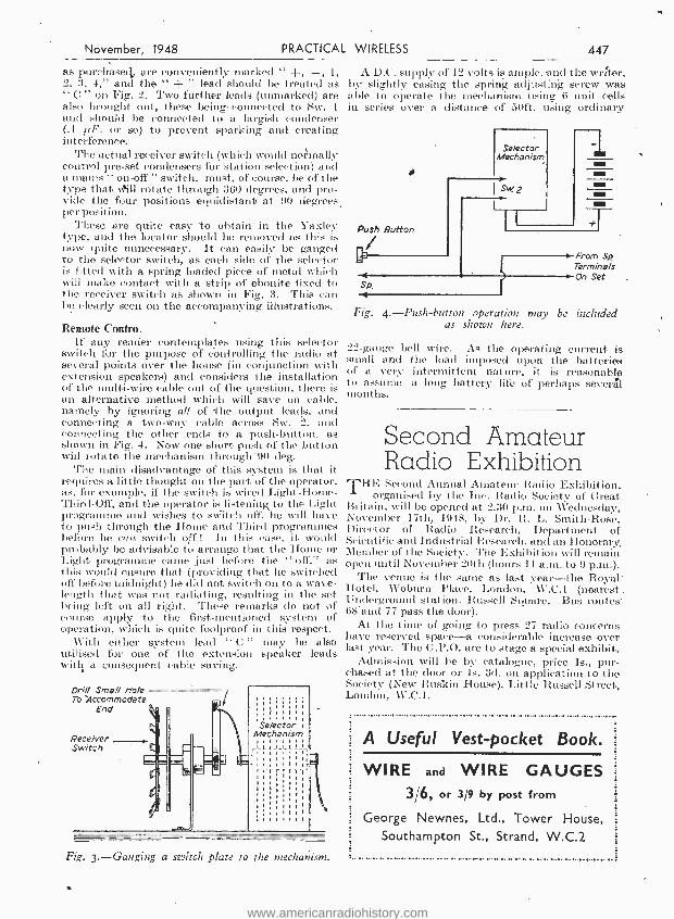
switch for the purpose of controlling the radio at several points over the house (in conjunction with extension speakers) and considers the installation of the multi -wire cable out of the question, there is an alternative method which will save on cable, namely by ignoring all of -the output leads, and connecting a two -way cable across Sw. 2, and connecting the other ends to a push- button, as shown in Fig. 4. Now one short push of the button will rotate the mechanism through -90 deg.
The main disadvantage of this system is that it requires a little thought on the part of the operator, as, for example, if the switch is wired Light -Home- Third -Off, and the operator is listening to the Light programme and wishes to switch off, he will have to push through the Home and Third programmes befi i'e he can switch off ! In this case, it would probably be advisable to arrange that the Home or Light programme came just before the " off," as this would ensure that (providing that he switched off before midnight) he did not switch on to a wave- length that was not radiating, resulting in the set being left on all right. These remarks do not of course apply to the first -mentioned system of operation, which is quite foolproof in this respect.
With either system lead " C " may be also utilised for one of the extension speaker leads with a consequent cable saving.
Drill Small Ho /e To 'Accommodate
End
Receiver Switch
Fig. 3.-Ganging a switch plate to the mechanism.
A D.C. supply of 12 volts is ample. and the writer, by slightly easing the spring adjusting screw was able to operate the mechanism. using 6 unit cells in series over a distance of 50ft. using ordinary
Push Baton -r
Sp. 4
Selector Mechanism
Sw 2
I
I-1
From Sp Terminals On Set .
Fig. 4. -Push- button operation may be included as shown here.
22 -gauge bell wire. As the operating current is small and the load imposed upon the batteries of a very intermittent nature, it is reasonable to assume a long battery life of perhaps severál months.
Second Amateur Radio Exhibition
THE Second Annual Amateur Radio Exhibition, organised by the Lie. Radio Society of Great
Britain, will be opened at 2.30 p.m. on Wednesday, November 17th, 1948, by Dr. R. L. Smith -Rose, Director of Radio Research, Department of Scientific and Industrial Research, and an Honorary, Member of the Society. The Exhibition will remain open until November 20th (hours 11 a.m. to 9 p.m.).
The venue is the saine as last year -the Royal-. Hotel,, Woburn Place, London, \\'.C.1 (nearest Underground station, Russell Square. Bus routes' 68'and 77 pass the door).
At the tinte of going to press 27 radio concerns have reserved space -a considerable increase over last year. The G.P.O. are to stage a special exhibit.
Admission will be by catalogue, price ls., pur- chased at the door or is. 3d. on application to the Society (New Ruskin House), Little Russell Street, London, W.C.I.
A Useful Vest -pocket Book.
WIRE and WIRE GAUGES 3/6, or 3/9 by post from
George Newnes, Ltd., Tower House, Southampton St., Strand, W.C.2
www.americanradiohistory.com
448 PRACTICAL WIRELESS November, 1948-
T -le New Emitron Cameras Details of the Latest E.M.I. Television Transmitting Equipment
as Used for the Olympic Broadcasts
BRITAIN'S greatest success at the Olympic Games was undoubtedly the excellence of the tele-
vision broadcasts. The wealth of detail and depth of focus of the pictures drew praise from com- petitors from all over the world, and a spokesman of the American team said publicly during a television interview that of all the things that had impressed him in Britain, television was foremost and was better than anything he had so far seen in the United States.
The E.3LI. Research Labor- atories at Hayes worked day and night to complete the new mobile van and C.P.S. Emitron cameras in time for the start of the Olympic events from the Empire Pool and the magnificent results achieved must have been a source of particular satisfaction to those responsible. Even the B.B.C., normally reticent on such matters, were constrained to pay tribute in the Radio Tintes to the engineers responsible.
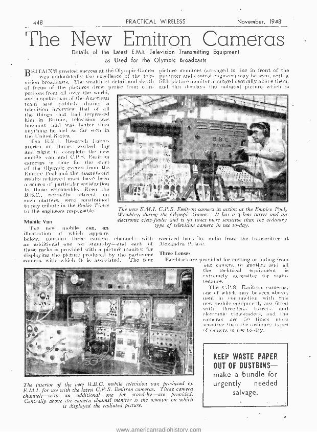
Mobile Van The new mobile van, an
illustration of which appears below, contains three camera channels -with an additional one for stand -by -and each of these racks is provided with a picture monitor for displaying the picture produced by the particular camera with which it is associated. The four
picture monitors (arranged in line in front of the producer and control engineer) may be seen, with a fifth picture monitor arranged centrally above them, and this displays the radiated picture which is
The new E.M.I. C.P.S. Emitron camera in action at the Empire Pool, Wembley, during the Olympic Games. It has a 3 -lens turret and an electronic view - finder and is 5o times more sensitive than the ordinary
type of television cannera in use to -day.
received back by radio from the transmitter at Alexandra Palace.
Three Lenses Facilities are provided for cutting or fading from
one camera to another and all the technical equipment is
The interior of the new B.B.C. mobile television van produced by
E.M.I. for use with the latest C.P.S. Emitron cameras. Three camera channels -with an additional one for stand -by -are provided. Centrally above the camera channel monitor is the monitor on which
is displayed the radiated picture.
extremely accessible for main- tenance.
The C.P.S. Emitron cameras, one of which may be seen above, used in conjunction with this new -mobile equipment, are fitted with three -lens turrets and electronic view- finders, and the cameras are 50 times more sensitive than the ordinary types of camera, in use to -day.
KEEP WASTE PAPER
OUT OF DUSTBINS- make a bundle for urgently needed
salvage.
www.americanradiohistory.com

November, 1948 PRACTICAL WIRELESS 449
A Microphone Amplifier A High -gain Instrument. Suitable for Moving Coil
or Ribbon Type Microphones
By " EXPERIMENTER ",
TO -DAY amateur constructors are quite competent at buiIcling loudspeaker amplifiers and obtaining successful performances from
them, but the problems attending the design of amplifiers for very small inputs (such as microphone amplifiers) are not so well understood. It is the purpose of this article to review the chief difficulties likely to be encountered in building an amplifier to follow a ribbon or moving -coil microphone and to suggest ways in which they may be minimised or overcome. It should be noted that the input circuit described is suitable only for the connection oflow- impedauco microphones, and that a circuit of a different type is regimired for high -impedance microphones of the piezo -electric or condenser type.
For design purposes the output voltage of the microphone is assumed to be -80 db. (relative to 0.775 volts). This output is very low, particularly for a moving -coil microphone, but this value is chosen so that there shall always be some gain in hand. The - output required from the amplifier is, say, 0 db. ; this is a value convenient for operating the most insensitive of high quality or P.A. ampli- fiers. The maximum voltage gain required from the amplifier is, hence, 80 db., more than can be obtained from a single high -slope valve, even allowing for the voltage step -up in an input transformer. Two. valves are necessary, and it is a good plan to use two high -slope pentodes of the SP-11 type, because they can provide more than 80 db. gain and the unwanted gain can be devoted to negative feedback. The provision of some feedback is very desirable to improve the linearity of the amplifier and to reduce valve noise and hum.
Some means of controlling gain is necessary and the method and position of the control in the circuit must be chosen with Care. If a conventional grid
Input Transformer
Input
I
High- Slope Pentodes
Output
Variable Voltage Negative Feedback
Fig. 1.-Basic circuit of the design discussed in this article.
circuit potentiometer is used, this should be situated at the input of the second valve, because there is no likelihood of the first valve being overloaded (and the second might), and it is desirable to render the hiss of the first stage as innocuous as possible.
An alternative and better means of gain control is by variable negative feedback, even though such a, control has a limited range. As two valves are dsed, it is convenient to apply variable voltage negativo feedback between the anode of time second valve and the cathode of the first.- This is time method adopted in the design to be described. The basic circuit of the amplifier is now clear and is illustrated in block schematic form in Fig. 1.
As the ribbon impedance is extremely low and is appreciably less than that of even a short micro- phone lead, it is customary to mount a transformer
Fig. 2. -A high -slope R.F. pentode used as a high gain A.F. amplifier.
in time base'of a ribbon mierop mone to step -up the impedance to, say, 600 ohms. S radar measures are, or Should be adopted with moving -coil microphones. Thus, the input impedance of timo' microphone amplifier must be 600 ohms and the turns ratio and secondary load ni.ust be chosen accordingly. Natur- ally, time ratio should be as large as possible, provided the transformer has the desired frequency response, but it is doubtful whether a turns ratio appreciably greater than 20 : 1 can be obtained in a practical component. For this ratio time secondary load should be 202 x 600 i.e., approximately 0.25 megohm. A grid- cathode circuit with an impedance as high as this is very susceptible to electrostatic pick -up of hum. and tho grid -lead and valve grid cap or pin should be thoroughly screened to. avoid this. The transformer also needs screening, but time pick -up here is magnetic in character and can be very severe, particularly if any mains transformers are nearby. To minimise this form of pick -up, time input transformer must be completely enclosed in a box of magnetic material of very high permeability, such as mumetal. The material should be reasonably thick, say, 1/16 inch, but if induction still occurs. the screening should be improved by using a greater thickness, or -and this is a better and cheaper method -two such boxes should be used, one mounted inside the other and spaced from it by
www.americanradiohistory.com
450 PRACTICAL WIRELESS -November, 1948
non -magnetic material such as brass. It is comfort- ing to know that if this screening is well done, the microphone amplifier and its mains unit can both be mounted on one small chassis, with negligible troúble from pick -up in the input circuit.
Input Leads To minimise pick -up in the microphone lead, this
should be of the balanced type, and the secondary winding of the microphone transformer should be centre -tapped and the centre point earthed. This precaution will permit the connection of microphone loads of practically any length without appreciable pick -up. Sometimes microphone leads are screened and the braiding earthed, but the author has not found this necessary.
The voltage gain of the input transformer is 20 (26 db.), and thus the valves must ,,provide 54 db. gain to make up the 80 db. required. It is desirable to obtain the maximum possible gain from the two valves so that the maximum of negative feedback can be used. The voltage gain of a pentode with a direct -coupled resistive load depends on the value of the load and the voltage of the H.T. supply, and to obtain very high gain, the anode load should be not less than about 100,000 ohms and the H.T. supply should be not less than about 300 volts. (It is assumed here that the screen potential is always adjusted to the optimum value for every change in operating conditions.) It is perhaps not generally realised how high the stage gain can be ; as an example, an SPRIT with an anode load of 150,000 ohms and an H.T. supply of 300 volts will give a gain of 250 times (48 db.), and these are the values of load and H.T. adopted in the amplifier. To obtain such
R8
T/
/:20`i-
C
a gain it is essential to use the optimum value of screen potential and this implies the optimum value of screen feed resistor. The method of supplying H.T. to the screen indicated in Fig. 2
is preferred to the alternative method using a potential divider across the H.T. supply, as it is to some extent self -compensating for changes in H.T. voltage. Fortunately there is a simple rule for determining the best value for RAR in Fig. 2. The opti- mum screen potential is approximately equal to the quiescent anode potential, and for maximum gain the P.D. across R;g must equal that across RI. Over a wide range of operating conditions the anode current is a fixed multiple, usually three or four times the screen current. Suppose the anode current is three times the screen current. For equality in P.D.s across Rse and RI, R g must be three times R1. As R, is 150,000, Rn must be 450,000 ohms.
To decide the value of the screen decoupling capacitor C, , consider the screen, control. grid and cathode of V1 as the électrodes of a triode. The " anode load '; of this valve is effectively the screen feed resistor and the decoupling capacitor in parallel. Since the screen potential must he as steady as possible during amplification the triode stage gain must be small. This, in turn, implies a small value of load. In practice a load of the order of 1,000 ohms is usually small enough and a decoupling capacitor of 2µ.F, the reactance of which is 1,600 ohms at 50 e /s, is generally satisfactory. Sometimes decoupling capacitors as small as 0.1µF are used, but such values may give a loss of low- frequency response unless this is made good by feedback or other means. It is not advisable to use electrolytic capacitors for screen decoupling,
cr C8 7II C9
O HT+ 350 Volts
Input
Output
O
Mains Transformer
Heater Winding For VI 5 V2
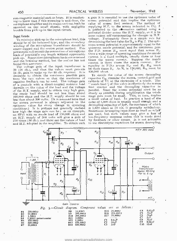
Rl R2 R3 R4 R5 R6 R7
Gain Control
Fig. 3.- Circuit diagram. Component R8 10,0900 R9 250,0000 RIO 250,0000 RI l 2,0000 RI2 1,5000 R13 150,0000 R14 500,0000
250,0000 50,0000 1,5000 5,0000 potentiometer 150,0000 500,0000 20,0000
values are as follows : RI5 20,0000 R16 250,0000 R17 39,0000
Cl O.IeF C2 50µF C3 2µF
C4 0.020 C5 32pF C6 32pF C7 2pF C8 32517 C9 0.02pF C10 12pF
www.americanradiohistory.com
November, 1948 PRACTICAL WIRELESS 451
for these often have leakage currents of a fraction of a milliamp which, in flowing through the very high screen-feed resistor, can cause an appreciable reduAion in steady screen potential. Good quality paper capacitors are therefore necessary at this point in the circuit. The decoupliiig capacitors are frequently connected between screen and earth. Whilst this is quite satisfactory if the cathode is also well decoupled to earth, it may cause unwanted effects if, as in the circuit under discussion, a feedback voltage is injected between cathode and earth. The safest course is to decouple the screen to cathode as shown in Fig. 2.
Cathode Bias Resistor The value of the cathode bias resistor R, may be
calculated at follows; For satisfactory operation of the pentodes the anode potential .preferably should not be less than about 100 volts. As the anode load is 150,000 ohms and the H.T. supply
-is 300 volts, it is clear that the anode current is 200,r150=133 mA. Assuming that the screen current is one-third of this, the cathode current will be approximately .1.8 mA. A grid bias value of -2.5 volts is satisfactory and the value of R, is
hence 2,500/1.8, approximately 1,500 ohms; The details of the feedback arrangements can now be considered. It is desirable that each valve should have a certain amount of current feedback independent of the voltage feedback used for controlling gain. About 10 db. of current feedback is obtained by omitting the electrolytic capacitors which are usually connected across the cathode resistors. The gain control is obtained by variable voltage feedback applied between the anode of V2, and the cathode of VI. This feedback is provided by R4 and R9 (Fig. 3) and it is clear from its position in the circuit that R4 also gives some variable current feedback on VI. It was con- sidered unnecessary to isolate 119 from the H.T. supply by including a fixed capacitor in the circuit at this point. The direct current through' the voltage feedback loop is only just over a milliamp and the steady P.D. across R4 has a maximum value of only 6 volts and does not affect the performance of VI M any way.
The values of RI and R9 are calculated to give a maximum of about 38 db. of feedback and this is also the volume range of the gain control.
(To be continued.)
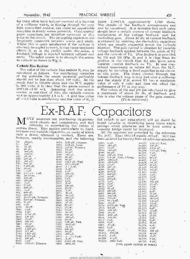
Ex-R.A.F. Capacitors MANY amatcurs are purchasing ex-govern-
ment chas-,i: and components, and find difficulty in ascertaining the values of
certain items. This applies particularly to fixed, trimmer and variable capacitors, on many of which only a stores reference io marked. These are, however, readily ascertainable, and the following
list (wl ich is not exhaustive) will no doubt be found valuable in identifying many items which perhaps could otherwise not be used unless a capacity bridge could be 'employed.
All the numbers are preceded by the reference No. 10/C. Thus 10/C-14 equals .0011,F. 10/C has been omitted for brevity from all reference numbers.
14. 15. 16. II. 96. 97. 317. 624. 627. 792. 79:,. 794. 701_,.
960. 962. WI. 96 t. 967. 964. Iraq. 970. 971. 97,4. :174. 0711. 978. 979. 1271. 24411. 2902. 2005. 2006. 2007. 2008. 2509. 2911. 2017. 5114. 2015. 2016. 5117. 20:17. 206G.
.001fir. 5pF. 111 pF, 40 pF. 1110 pc. .002 ,/ F. iii l. 501) pr . ., .001 //1.% 51111 pr. 1.000 4F.
2.5 -.- 2.5+1 pr. An above. 100 pl,'. .005 illf. .111F. 75 pr. sue pr. .5 pl . 600 pF. 200 ple. 10-115 pF. Trimmer. 5-09 pF. Trimmer. 15 Id". 4 pi'.
.020F. 2 pF. 4 pr. 4.55111,F. MO pf. 25 pl.'. 240 pl,% so pF. .002 pi'. 1.720 pr 577 pr 1,470 1.4%
0,170 pr 300 IA% 5 pF. 3-18 pF. Trimmer.
2a70. 21)71. 2072. 2077. 2117. 2076. 207::. 5)79. 20,2. 7,0:1 . 7041 2192.
.2417'..
2274. ,4279. 2240; 2375. 2424. 2599. 2621. 2625. 2626. 9627. 3629. 2670. 2649. 7027. 2047. 7055. 7064. 7100. 7124. 71214 :1192. 3105. 3196. 3303. 3796. 3399. 3401. 3402. 3430.
3-20 pF. Trimmer. 3-18 p1'. (tang'. 2-A pF. Trimmer. 1r) pi,. :;I/ pF. 41113 pp, 50 pf. 50 pF. 2-6.5 pr., Vari. .05-1-.0511F. J. +.1 ,01?. .10. (1111Y;(1".
.25 pi".
4 pl'. .5,0P. 100 ¡F'. 25 0F. .1 pl.% .01 /1F. .005 /FF. .005 ple. .02pF. .05 01". 65 Inf. 25 pf. 5)) pl... .01 pi', ;300 pr .001 ,/(1*. 30 pl.'. 5-60 pi,. Vari. .0025 (1'. .01 ,, F. 300 pl.% 10 1,1% .001 0F. .1 + .1 +.1 pF. .5 p.F. 8-105 pi'. Vail .0001 pi'.
35(13. 358)); 3787. 3788. 3789. 3790. 3791, 4099. 4190. 42:12. 4250. 4260, 4264. 4271. 4501. 4502. 4572. 4672. 46:17. 4922 4927. 4995. 5752. 5484. 55114. 5645. 5874. 5875. 7901. 7009. 8009. 8010., 8275. 8284. 8382. 9097,
10.161.. 4(1.11):, 10.221. 10,554.
8 pF. .001 pr. 16,0F. .005 0F. 60 pF. 160 141".
100 .0993 p .0091 pF. 25 p ..001 0F, 97 2110 pF. 00
51) pl.'. 500 pr. 1 /IF. 3 pf. 2 pr 70 pF. 160 pr. 101) .(105 HF. 250 pf. 16+8 fir. .01 9-175 pF. 3-4 pr. .001 pr. .01 ple. .0005 plf. .002 0F. 2 8 fib'. .2501f. 1 pr. .050.
.005 pr.
.1 fir.
.05 pP.
.0005 Vari. (Vari.
0.
42 Gang.
10.227. 10,228.
.10,229. 10.270. 10.1101. 10.5.54, 1(1,568. 311,607. 10,629. 10.944. 11,127. 11,124. 11.125, 11,126. 11.170. 11,17t. 11,140, 11,156, 11.157. 11,17(1. 11,482. 11.445. 11,658, 11.694, 11.744. 11,757, 11.751. 11,755. 11,756, 12,111. 12.781. 12,574. 1 pl.%
7-75 pi,. Vail. 161) pr. 1.050 pF. 7-17. pr 3 pr. .1 fir. 50 pr. 15 pr. 411 /tr. 70 pl.'.
.02 /,1.%
.1 p
.5 fir.
.npr.
.11114 pr.
.05 pF.
.1 pV.
.1 /IF. 4 pr. 50 pr. 200 ¡W. .007,04% 1.25 /./4'. .01 pr. .(15 4 fir. .25 fir. 411 pr. 25/li".
13,194. 8 pr. 17,212. 1611f. 17.258. 4 13,260. 4 pi'. 13.264.. .001 pr. 14,211. 40 pr. 14,610. .5 pr. 14,719. 2 pi?. 14,757. 4 pi'.
equals variable or preset.)
www.americanradiohistory.com
2`t PRACTICAL WIRELESS November, 194$'
A Lig -tweiç _at Pick -up A Needle Armature Instrument Without Rubber Damp
By G. H. LEVERSEDGE
THE pick -up to be described has been in service for several veers anti gives very good reproduction. It will work satisfac-
torily with a needle pressure of half an ounce on the heaviest recordings, and will not be found too difficult to make by anyone accustomed to light instrument work. It is or the. needle armature type, using H.M.P. Silent Stylus or Columbia 99 needles. A special feature is that no rubber is used in its construction, and there is, therefore, no fear of gradual deterioration of performance which is always present when even the best quality rubber is used for damping, or as a bearing for-
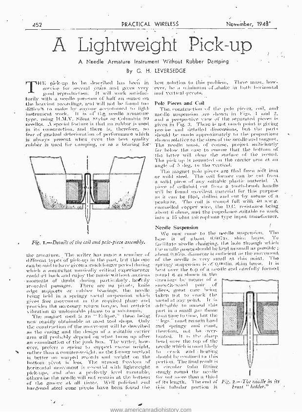
Fig. r.- Details of the coil and pole piece assembly.
the armature. The writer has made a number of different types of pick -up in the past, but this one can be said to have given a much longer period l during which a somewhat musically critical experimenter could sit back and enjoy the music without anxious
- moments of doubt during particularly. hetfvily recorded passages. There are no pivots, knife edge supports or rubber bearings, the needle being held in a springy metal suspension which gives free movement in the required plane and provides the necessary return torque, but restricts vibration in undesirable plaises to a tniuintuih.
The magnet used is an " Eclipse," these being now readily obtainable at most tool shops. Only the construction of the movement will be described as the casing and the design of a suitable currier arm will probably depend on what, turns up after an examination of the junk box. The writer, how- ever, prefers a spring to support excess weight, rather than a counter -weight, as the former method is better on warped records and weight on the bottom pivot is less. The utmost freedom of horizontal movement is essential with lightweight pick -ups, and also a perfectly level turntable, otherwise the needle will not remain at the bottom of the groove at all times. «'ell polished and hardened steel cone pivots have been found the
ng
best solution to this problem. There must, how- ever, be a minimum. of .shake in both horizontal and vertical -pivots. -
Pole Pieces and Coil The. construction -of the pole pieces, coil, and -
needle suspension are shown in Figs. I and 2, and a perspeetivc view of the separated pieces is given in Fig. 3. There is not nu elt point is giving precise and detailed dissensions, but the parts should be made approximately to the proportions shown relative to the sizes of the needle and magnet. The needle must, of course, project sufficiently far below the ease to ensure that the bottom of the latter will clear the surface of the record. Tite pick -up is mounted on the carrier arm at an angle of S deg. to the vertical.
The magnet pole pieces are filed from soft iron or mild steel. 'l'he coil former can be cut from ;i solidi piece- of any suitable plastie material. A Hece of celluloid cut from a tooth -brush handle will be found excellent material for this purpose as it can be filed, drilled and cut by means of a penknife. The coil is wound full with 40 s.w.g. enamelled copper wire, the D.C. resistance being about li ohms, and the impedance suitable to work into a 15 ohm microphone type input transformer.
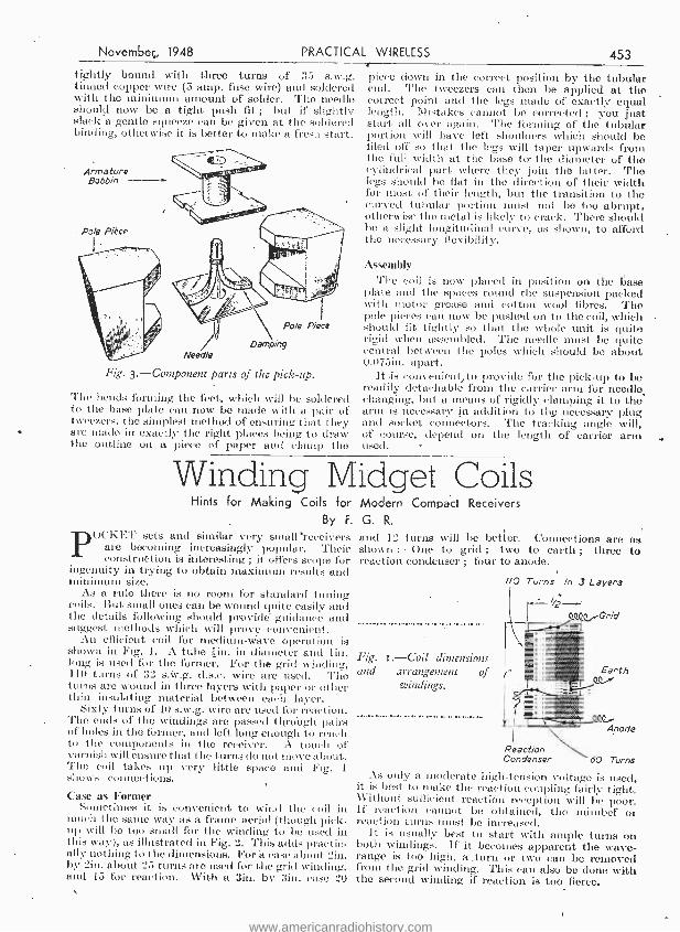
Needle Suspension We new come to the needle suspension. Tito
]Rase is of about 0.007in. - shins brass. To facilitate needle changing, the hole through which the needle passes should be kept as small as possible ;
about 0.0.iin. diameter is s IIticient as the movement of the needle is very sm:;ll at this point. The springy suspension is of if.00tin. shins brass. ]t is bent over the top of a needle and carefully formed round it as shown in the drawings by means of a smooth -nosed pair of pliers, great care being taken not to crack the metal at any point. It is advisable to anneal this part in a small gas flame from time to time, but the " legs " must remain hard Tad Springy and must, therefore, not be over- heated. It is the sharp bendI over the top of the needle which is most- likely to crack and : heating should be confined to this portion. The final result, is a circular tube fitting smugly round the needle for not more than a third of its length. The end of Fig. 2. -Tile needle in its this tubular portion is brass "-holder."
:v/ilíYi;f9'/Fi .aho
www.americanradiohistory.com
Novembeç, 1948 PRACTICAL WIRELESS 453
tightly bound with three turns of 35 s.w.g. tinned copper wire (5 amp. fuse wire) and soldered with the minimum amount of solder. The needle should now be a tight push fit ; but if slightly slack a gentle squeeze can be given at the soldered binding, otherwise it is better to snake a fresh start.
Armature Bobbin
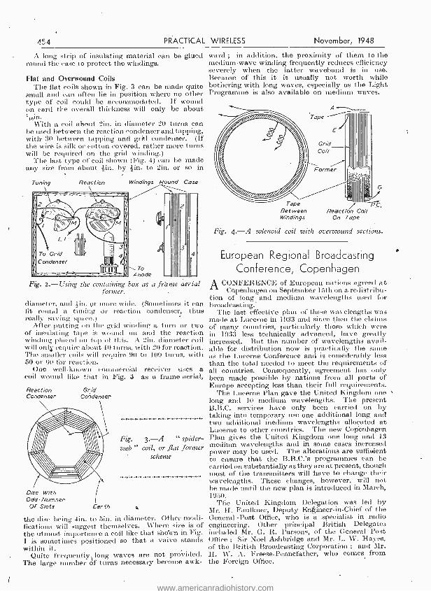
Fig. 3.- Component parts of the pick -up.
The bends forming the feet, which will be soldered to the base plate can now be made with a pair of tweezers, the simplest method of ensuring that they are made in exactly the right places being to draw the outline on a piece of paper and claurp the
piece down in the correct position by the tubular end. The tweezers can then be applied at the correct point and the legs made of exactly equal length. Mistakes cannot be corrected ; you just start all over again. The forming of the tubular portion will have left shoulders which should be filed off 'so that the legs will taper upwards from the full width at the base to- the diameter of the cylindrical part where they join the latter. The legs should be flat in the direction of their width for most of their length, but the transition to the curved tubular portion must not be too abrupt, otherwise the metal is likely to crack. There should be a slight longitudinal curve, as shown, to afford the necessary flexibility.
Assembly The coil is now placed in position on the base
plate and the spaces round the suspension packed with motor grease and cotton wool fibres. The pule pieces can now be pushed on to the coil, which should lit tightly so that the whole unit is quite rigid when assembled. The needle must be quite central between the poles which should be about 0.075u. apart.
It .is convenient;to provide for the pick -up to be readily detachable from the carrier arm for needle changing, but a means of rigidly clamping it to the arm is necessary in addition to the necessary plug and socket connectors. The tracking angle will, of course, depend on the length of carrier aria used.
Winding Midget Coils Hints for Making Coils for Modern Compact Receivers
By F.
POCKET sets and similar very small `receivers are becoming increasingly popular. Their construction is interesting ; it offers scope for
ingenuity in trying to obtain maximum results and minimum size.
As a rulo there is no room for standard tuning coils. But small ones can be wound quite easily and the details following should provide guidance and suggest methods which will prove convenient.
An efficient coil for medium -wave operation is shown in Fig. 1. A tube ¿in. in diameter and lin. long is used for the former. For the grid winding, 110 turns of 33 s.w.g. d.s.c. wire are used. The turns are wound in three layers with paper or other thin insulating material between each layer.
Sixty turns of -10 s.w.g. wire are used for reaction. The ends of the windings are passed through pairs of holes in the former, acct left long enough to reach to the components in the receiver. A touch of varnish will ensure that the turns do not move about. The coil takes up very little space and Fig. 1 situ WS connections.
Case as Former Sometimes it is convenient to wind the coil in
much the saune way as a frame aerial (though pick- up will be too small for the winding to be used ill this way), as illustrated in Fig. 2. This adds practic- ally nothing to the dimensions. For á case about tin. by tin. about 25 turns are used for the grid winding, and 15 for reaction. With a Sin. by Sin. ease 20
G. R.
and 12 turns will be better. Connections are as shown : One to grid ; two to earth ; three to reaction condenser ; four to anode.
//O Turns In 3 Layers
Fig. i. -Coil dimensions and arrangement of
windings.
QIQ.Grid
Reaction Condenser
Earth ecr
eee,. Anode
60 Turns
As only a moderate high -tension voltage is used, it is best to make the reaction coupling fairly tight. Without sufficient reaction reception will be poor. if reaction cannot be obtained, the mimbef 01 reaction turns must be increased.
It is usually best to start with ample turns on both windings. if it becomes apparent the wave - range is too high, a .turn or two can be removed from the grid winding. This can also be done with the second winding if reaction is too fierce.
www.americanradiohistory.com
454 PRACTICAL WIRELESS November, 1948
A long strip of insulating material can be glued round the case to protect the windings.
Flat and Overwound Coils The flat coils shown in Fig. 3 can be made quite
small and can often lie in position where no other type of coil could be accommodated. If wound on card the overall thickness will only be about li0in.
With a coil about 2in. in diameter 20 turns can be used between the reaction condenser and tapping, with- 30 between tapping and grits condenser. (If the wire is silk or cotton covered, rather more turns will be required on the grid winding.)
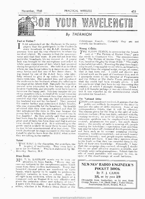
The last type of coil shown (Fig. 4) can be made any size from about ¡yin. by ¡in. to 2in. or so in
Tuning Reaction Windings Round Case
To Anode
Fig. z, -Using the containing box as a frame aerial former.
diameter, and in. or more wide. (Sometimes it can fit round a tuning or reaction condenser, thus really saving space.)
After putting on the grid winding a turn or two of insulating tape is wound on and the reaction winding placed on top of this. A 2in. diameter coil will onl - require about 40 turns, with 20 for reaotion. The smaller coils will require 90 to 100 turns, with 50 or 60 for reaction.
One well -known commercial receiver uses a coil wound like that in Fig. -3 as a frame aerial,
Reaction Grid Condenser Condenser
Disc With Odd - Number Of S lots Earth
Fig. 3.-A " spider - web " coil, or flat former
scheme
a
the disc being 4in. to 5in. in diameter. Other modi- fications *ill suggest themselves. Where size is of the utmost importance a coil like that shown in Fig. 1 is sometimes positioned so that a valve stands within it.
Quite frequently long waves are not provided. The large number of turns necessary become awk-
ward ; in addition, the proximity of them to the medium -wave winding frequently reduces efficiency severely when the latter waveband is in use. Because of this it is usually not worth while bothering with long waves, especially as the Light Programme is also available on medium waves.
Tape ----n //1
Grid Coi/
Former
Tape Between Windings
Reaction Coi/ On Tape
Fig. 4.-A solenoid coil with overwound sections.
European Regional Broadcasting Conference, Copenhagen
ACONFERENCE of European nations agreed at Copenhagen on September 15th on a redistribu-
tion - of long and medium wavelengths used for broadcasting.'
The last effective plan of these wavelengths was made at Lucerne in 1933 and since then the claims of many countries, particularly those which were in 1933 less technically advanced, have greatly increased. But the number of wavelengths avail- able for distribution now is practically the same as the Lucerne Conference and is considerably less than the total needed to meet the requirements of all countries. Consequently, agreement has only been made possible by nations from all parts of Europe accepting less than their full requirements.
The Lucerne Plan gave the United Kingdom one long and 10 medium wavelengths. The present B.B.C. services have only been carried on by taking into temporary use one additional long and two additional medium wavelengths allocated at Lucerne to other countries. The new Copenhagen Plan gives the United Kingdom one long and 13 medium wavelengths and in some cases increased power may be used. The alterations are sufficient to ensure that the B.B.C.'s programmes can be carried on substantially as they are at present, though most of the transmitters will have to change their wavelengths. These changes, however, will not be made until the new plan is introduced in March, 1950.
The United Kingdom Delegation was led by Mr. H. Faulkner, Deputy Engineer -in -Chief of the General -Post Office, who is a specialist in radio engineering. Other principal British - Delegates included Mr. G. R. Parsons, of the General Post Office ; Sir Noel Ashbridge and Mr. L. W. Hayes, of the British Broadcasting Corporation ; and Mr. H. W. A. Freese - Pennefather, who comes from the Foreign Office.
www.americanradiohistory.com
November, 1948 PRACTICAL WIRELESS 455
Fact or Fiction ? I\\AS astonished at the disclosure in the
papers that the participants in the Cinderella story broadcast in the R.A.F. Heunion Pro-
gramme were not the true characters to whom the incident related. My concern is that the announce- ment said that they were. If you slid not hear this particular broadcast, let. me recount it. A young lady was brought to the microphone and asked to relate some experience of hers which had occurred during her period of service. She told of an incident where she was being taken to a dance in one of the army lorries and lost one of her dance shoes. It was found by one of the R.A.F. boys, who play- fully refused to give it up unless she agreed to dance with him. She married him, and introduced the audience to her husband, whom she called on to the stage of the Albert Hall. Naturally the reporters present were interested in this human story of a modern Cinderella, and promptly went backstage to interview the happy pair. You may imagine the joy of the reporters when, instead of the usual romantic stuff, the girl shyly informed theca that she was not married and that the man she had introduced as her husband was not her husband ! They pursued the matter farther and interviewed Ralph Reader, who was responsible for the broadcast. He frankly admitted that they were not married and that ho had introduced the item in this way because the young lady to whom the incident occurred was in Los Angeles ! He then naïvely said that no harm had been done by this deception. I suggest that a great deal of harm has been done and that a serious view should be taken of it. It is misleading to the public and it is likely to cause them to cast doubts on any future announcement of a true story. The truth should not be stage- managed in this way, and 1 shall be glad to learn from the B.B.C. what action they are taking in the matter.
Talent " THE B.B.C. is the champion. the guardian, the
inspirer of mediocrity. They even have a name for it- Talent." This is a statement by Mr. Beverley Baxter, M.P.
Brass Bands MR. T.' L. LAIDLAW wants me to turn my
attention to brass bands. " Every day my ears are tortured by the cacophonous noises which comp from these soulless instruments. Every clay beautiful classical pieces are murdered I'y bands, which appear to be unable to proclii, e the slightest variation in tone or volume. Bras is all right in an orchestra, where in the hands of a composer such as Wagner it is very effective and gives the orchestra colour and richness of tone." I agree with this reader. I do not like brass hands either, whether it be Foden's Brass Band or the
Coldstream Guards. Certainly they are not suitable for broadcasts.
Wrong Crédits THE RADIO TIMES, in announcing the broad-
cast of " The Picture of Dorian Gray," gave the credit to Constance Cox. The amrouucerncnt read, " The Picture of Dorian Gray, by Constance C'ox, based on the,play by Oscar Wilde." This really is just a bit too much. Knowing the play frombegin- ning to end, I was unable to see where, as broadcast, it differed from the original script, except, of course, that it had been cut. I could not discern any original work on the part of Constance C'ox, and so I promptly wrote to the Director of Programmes and the Editor of Time J adi° Tithes, pointing out that the credit had been wrongly given. I will let you know what they have to say concerning this practice, of winch 1 strongly disapprove. When I read it I thought perhaps it was an editorial error, but it was repeated in the announcement which preceded the broadcast.
The National Drive
FROM correspondence received, it appears that the public are unlikely to respond to the drive .to
improve the sales of radio receivers. None of my correspondents thinks that it will be effective. The reasons given for the drop in the sales of radio receivers include : Price too high ; satisfied with the existing receiver ; no need for second set because extension speakers can be employed with remote control ; programmes too poor ; too much dance music ; the novelty of radio is wearing off; people waiting for television ; expectation that purchase tax may be taken off ; technical developments have. not been such as to warrant scrapping existing receivers ; world too - unsettled ; not so much money about as formerly ; and, people require radiograms, but cannot get them. 1 pass these opinions along to the trade so that they can consider them in the light of their own knowledge. Personally, I hope that the campaign does succeed, although I should like to see more all -wave receivers available, and certainly more radio- gramophones. 1 think that the sale of small portables will continue to rise, in spite of the disadvantage of small batteries.
NE WNES' RADIO ENGINEER'S POCKET BOOK
By F. J. CAMM 3/6, or by post 3/9
Obtainable from booksellers, or by post from George Newnes, Ltd. (Book Dept.), Tower House,
Southampton Street, Strand, W.C.2.
www.americanradiohistory.com
456 PRACTICAL WIRELESS November, 1948
Using he Oscilloscope -2 In thi Month's Article, H. R. McDERMOTT Describes
Methods of Modulation Measurement
THE process of frequency calibration is essentially one of frequency comparison, the unknown frequency being compared against a standard
reference oscillation oscillator. Now there is no need to inquire ` ` From where do we get one of these ? " for practically every house in Great Britain has one in the form of the time -controlled 50 cycle mains. Actually, what we do is to compare the unknown frequency against the time base, which has pre- viously. been set in some simple ratio to the mains frequency. You may suggest that your time base is none too stable and inclined to drift a little, but this is not important as the process of plotting each point is completed in a very short while -well under a minute. The short -period stability of most gear is very high, even if made just reasonably
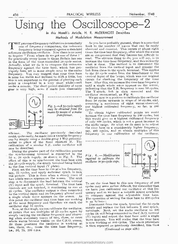
Fig. 5. -A 50 cycle supply may be obtained from the mains by means of a mains
transformer.
efficient. The oscillator previously described could, quite easily, be made into a variable frequency one by simply using a double gang 1 MQ potentio- meter in place of the fixed resistors R. The calibration of a similar V.F. audio oscillator will now be described.
During the greater part of the calibration process the synchronising terminal is connected to the 50 v. 50 cycle supply, as shown in Fig. 5. The effect of this is to synchronise the time base with the 50 cycle supply, the synch. terminal being linked to the free vertical input (Y plate).
First, set the time base to run at a low frequency, say, 25 cycles, and apply sufficient synch. to lock the picture. This is done when a steady trace of two whole waves appears on the screen. The next step is to disconnect the lead between the vertical (Y) input and the synch. terminal. The time base controls are not touched, it continuing to run at 25 cycles. The oscillator output is then connected to the vertical input and its frequency altered until a single whole wave appears on the screen. At this point the oscillator and time base are working at the same frequency and therefore we mark the oscillator dial 25 cycles.
Now, at this stage, we can calibrate the oscillator, at points that are multiples of 25 cycles apart by simply varying the oscillator frequency and observ- ing when stationary traces- of two, three, or more whole waves become visible on the C.R.O. screen. At these positions the oscillator is working at two, three, etc., times the time base frequency, i.e., 50, 75, 100 c.p.s.
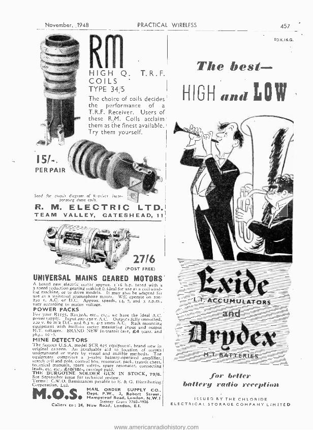
As you have probably guessed, there is a practical limit to the number of waves that can be easily observed and counted. This occurs at about eight times the time base frequency, after which the waves are so compressed that they become too difficult to read. The obvious thing to do, you will say, is to increase the time base frequency, and this is exactly what is done. The method is to disconnect the oscillator from the vertical input and remake the link from there to the synch. terminal. This applies to the 50 cycle mains from the transformer to the vertical input of the 'scope, which was our original circuit for checking the frequency of the time base. - After this, we increase the time base frequency until a single whole wave appears on the screen, indicating that the T.B. frequency is now 50 cycles. The Y- synch. link is then removed and the oscillator reconnected, as Fig. 6.
We are now in a position to calibrate the oscillator from 50 cycles upwards in steps of 50 cycles, and, assuming a maximum of eight waves observed, our highest calibrated frequency, so far, is 400 cycles.
To obtain higher calibrated points we could increase the time base frequency to 100 cycles, but this would give us a highest calibrated frequency of only 800 cycles, which is not a great increase in the audio 'range. So what we do next is to adjust the time base to a considerably higher frequency, say, 400 cycles, and so obtain' multiples of this frequency in our calibration of the oscillator.
Fig . 6.- Modification required to calibrate the oscillator in so -cycle steps.
Audio Osc,
240v..
To set the time base to this new frequency of 400 cycles may seem rather difficult, but remember that we have just calibrated our oscillator at 'this fre- quency and so we have a suitable source available to compare against the adjustable time base. The operation of setting the time base to 400 cycles is as follows :
Disconnect from the synch. terminal the 50 cycle supply and replace the link between Y and synch. terminals. Next, set the audio oscillator to 400 cycles (it still being connected to the C.R.O. vertical (Y) input) and adjust the time hase until a single wave appears. You will realise that the timo base is now working at 400 cycles. The whole procedure is then repeated as previously described, this time
(Continued on page 459.)
www.americanradiohistory.com
November, ..1948 PRACTICAL WIRELESS
HIGH Q. T.R.F.. COILS ' TYPE 34/5 The choice of coils decides the performance of a
T.R.F. Receiver. Users of these R.M. Coils acclaim them as the finest available. Try them yourself.
15/ -. PER PAIR
Send for circuit diagram of Receiver incor- porating these coils.
R. M. ELECTRIC LTD. TEAM VALLEY, GATESHEAD, 11
UNIVERSAL MAINS GEARED MOTORS A brand new electric motor approx. r a h.p. fitted with 3 speed reduction gearing making it ideal for use as a coil wino - ing machine, or to drive models. It may also be adapted for use as a universal gramophone motor. Will operate on 200- 250 v. A.C. or D.C. Approx. speeds, 04, 7, and 3 r.p.m., vary according to mains voltage. POWER PACKS For your RI r55, RII32A, etc., etc., we have the ideal A.C. power supply. Input zoo -z5o v. A.C. Outputs fully smoothed, 220 v. 8o m a D.C. and 6.3 v 4-5 amps A.C. Rack mounting equipment with built -in meter measuring input and output H.T. voltages. BRAND NEW in transit case, £4 (carr. and pkg., to-). MINE DETECTORS The famous U.S.A. model SCR 625 equipment, brand new in original cartons. An invaluable aid CO location of metals underground or water by visual and audible methods. The equipment comprises a 3 -valve battery- operated amplifier, search coil and pole, control box, resonator, pack, transit chest, technical manuals, spare valves, spare resonator, connecting leads, etc. etc., £10/10/ -, carriage paid. THE BURGOYNE SOLDER GUN IN STOCK, 79/6. See September issue for technical review. Terms : C.W.O. Remittances payable to E. & G. Distributing Corporation, Ltd.
MAIL ORDER SUPPLY CO., Dept. P.W., 3, Robert Street, Os Hampstead Road, London, N.W.I
Stepney Green 2760 -3906 Callers to :14, New Road, London, E.I.
457 f
EDX.I6.G.
The best
HI3H and LOW
for better battery radio reception
ISSUED BY THE CHLORIDE ELECTRICAL STORAGE COMPANY LIMITED
www.americanradiohistory.com
458 PRACTICAL WIRELESS November, 1948
AMBITIOUS ENGINEERS HAVE YOU HAD YOUR COPY OF "ENGINEERING OPPORTUNITIES "? Whatever your age or experience- whether you are one of the " old school " or a newcomer to Engineering anxious to hold your position under post -war conditions -you must read this highly informative guide to the best paid Engineering posts.
The Handbook contains among other intensely interesting matter, particulars of B.Sc., A.M.LMech.E., A.M.I.E.E., A.M.I.M.I., A.M.I.P.E., A.M.Brit.I.R.E.,
CITY & GUILDS, CIVIL SERVICE, and other important Engineering Examinations, out- lines home -study courses in all branches of CIVIL, MECHANICAL, ELECTRICAL, AUTOMOBILE, RADIO, TELEVISION, AERONAUTICAL and PRODUCTION ENGINEERING, DRAUGHTSMANSHIP, GOVERNMENT EMPLOYMENT, BUILDING and PLASTICS, MATRICULATION, etc., and explains the unique advantages of our Employment Department.
WE DEFINITELY GUARANTEE ' NO PASS -NO FEE' If you are earning less than £10 a week you cannot afford to miss reading " ENGINEERING
OPPORTUNITIES "; it tells you everything you want to know to make your future secure and describes many chances you are now missing. In your own interest we advise you to
write for your copy of this enlightening guide to well -paid posts NOW -FREE and without obligation.
BRITISH INSTITUTE OF ENGINEERING TECHNOLOGY 409, SHAKESPEARE HOUSE, 17, 18 & 19, STRATFORD PLACE, LONDON, W.I.
THE B.I.E.T. IS THE LEADING 'INSTITUTE OF ITS,- KIND IN THE WORLD
THE A.C.R.1155 COMMUNICATIONS RECEIVER. This superb R.A.F. 10 valve superhet receiver, covering 75 kcis -18.0 mcís. In 5 wavebands, is now available for use on A.C. mains, and complete with speaker, at ONLY £18/10/ -. An illustrated, fully descriptive leaflet is available on request.
It.1132.A COMMUNICATIONS RECEIVERS. -A superb U.H.F. receiver, covering 100 -124 me /s. Incorporates large 180 degrees dial with slow motion tuning, and 0 -.5 mA. tuning meter. Chassis tropically treated. Complete with calibration chart, circuit diagram. part lists, and valves. ONLY 99/6 (carriage, etc.. 10 / -).
R.109 COMMUNICATIONS RECEIVER. An ex -Army superhet, covering 1.8 -8.5 me ,is. in two bands. Circuit consists of RF amp., mixer with separate local oscillator, 3 stages of combined signal detector, IF and A.V.C. and first AF, followed by an output stage. A BFO can be switched in for the reception of CW. Has built in 31n. speaker or can be used with 'phones. Power supply from 6v. D.C. source to vibrator power unit, which can be removed and set, then operated from 2v. L.T. and H.T. batteries. Complete in every way, and supplied with spare vibrator and valves and instruction book. ONLY £6/15./- (carriage, etc., 10 / -.)
SHORT -WAVE CONVERTERS.-Ex.-R.A.F. RF units. operating from 6.3v. and 240v. IF output 7 me /s. Types 24 and 25 operate on 5 pre -set frequencies and cover 15 -30 me /s. and 40 -50 me /s. respectively. Easily adaptable to tunable units by replacing ceramic switch with 3 ganging type 15 pf con- densers. ONLY 16/6 (Postage 1/8) or BRAND NEW IN CAR- TONS, 25/ -. Types 26 and 27 are tunable converters, covering 50-65 and 65 -85 me /s. respectively. They are fitted with a Sin. slow motion illuminated dial. ONLY 27/6 (Postage 1/6). or BRAND NEW IN CARTONS, 35' -.
C.W.O. please, S.A.E. for Lists.
U.E.I. CORP THE RADIO CORNER
138, Grays Inn Road, London, W.C.1 'Phone : TERminus 7937.
Open until 1 p.m. Saturdays ; we are 2 mins. from High Holborn, 5 mins from Kings Cross.
Southern Radio's Wireless Bargains BENDIX COMMAND RECEIVERS. -Type B.C.453 (190- 550 ke /s), B.C.454 (3 -6 mess.), B.C.455 (6 -9 megs.). Complete with Six Valves : (3) 12SK7 ; (1) 12SR7 ; (1) 12K8 ; and (1) 12A6. Brand New in sealed cartons, 35/- each. plus 1/6 postage. These Receivers are ideal for quick conversion to Q Fivers, Car Radios and standard Receivers. A few only of B.C.455 modified to 28-41 megs. ; ideal for tele- vision sound, 50 /- each, plus 1 6.
" DELCO " RAND GENERATORS, 6 volts 4 amps. Hand - speed 110 r.p.m. Brand new with spare brushes, 17/6 each. CONTACTOR TIME SWITCHES by Venners or Smiths. Beautiful clockwork 10 -hour movement. Adaptable for time switches or master clocks. Brand new in soundproof case, 15/- each, plus 1/4. BENDIX RADIO COMPASS RECEIVERS, type MN 26Y. Ranges : 150 -325 kc!s, 325 -695 kc /s and 3.4 -7 megs. Twelve valves : (2) 6N7, (5) 6K7, (1) 6138. (I) 6F6, (2) 6J5 and (1) 6L7. Complete brand new with 28 -volt Generator. £5, plus 10 /- carriage and packing. R.A.E. BOMBSIGHT COMPUTERS, complete with Sperry Gyro. (3) 28 -volt Motors. Gearing, Barometric Bellows and Counters, etc., etc. Ideal for model makers and experimenters. Brand new, 55/ -, plus 5/ -. MOVING COIL HEADSETS.- Headphones and microphone with lead and plug. Brand new, 12/8. Lufbra Hole Cutters. -Adjustable for use on wood. metal, plastics, etc., 5 / -,plus 4d. R.A.F. Morse Keys, 1i8, plus 4d. 15 /- per dozen, prbs 1/ -. Permanent Crystal Detectors, 2/6, plus 3d. Throat Microphones, boxed with lead and plug, 5/ -. Recording Blanks. -51 inches, 1/- each, plus 3d. ; 10/6 dozen, plus 1 / -. Westectors. WX6 and W112, 8,'- per dozen, plus 4d. Lucas Inspection Lamps complete with lead and plug, 3'6. Tannoy Carbon Mike Inserts, 2/6, plus 3d. BATTERIES. -M.C.R.I. 90 volts and 71 volts, 6 6. plus 9d. 671 volts " Ever -Ready Minimax," for personal sets, 5/6, plus 4d. Sealed cartons of five, 25/- plus 1/- ; 221 volts and 45 volts combined. 5/8 plus 9d. ; sealed cartons of four, 20/- plus 1/ -. 221 volts, 4/6, plus 6d. Sealed cartons of four. 16' -, plus 1 / -. 11 volts, ideal for bell batteries, etc., 3/- each plus 6d. Sealed cartons of six. 16 / -, plus 1 / -. All Batteries uncondi- tionally guaranteed. All Radio Publications previously advertised still available. Full list of publications ltd.
SOUTHERN RADIO SUPPLY, LTD. 46, Lisle Street, London, W.C. Gerrard 6653.
www.americanradiohistory.com
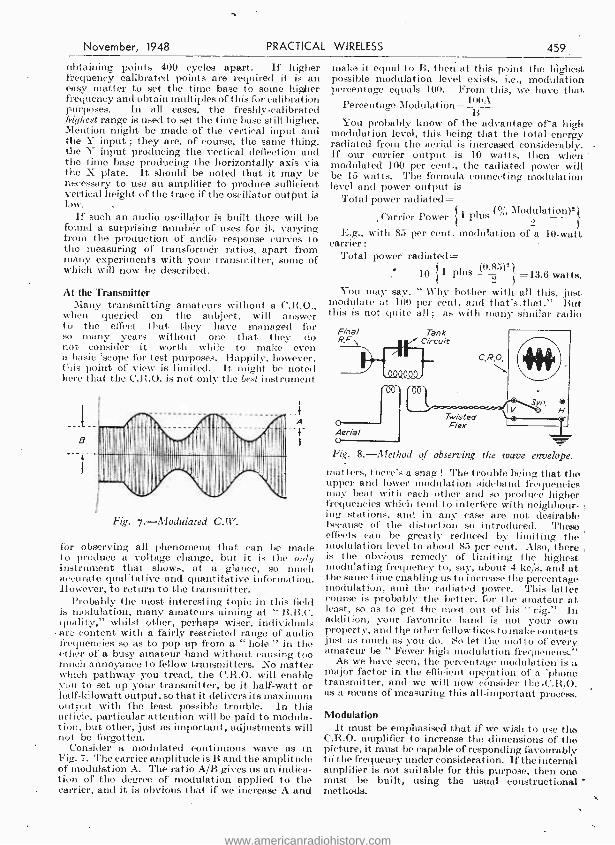
November, 1948 PRACTICAL WIRELESS 459
obtaining points 400 cycles apart. If higher frequency calibrated points are required it is an easy matter to set the time base to some higher frequency and obtain multiples of this for calibration purposes. In all cases, the freshly- calibrated highest range is used to set the time base still higher. Mention might be made of the vertical input and the Y input ; they are, of course, the same thing, the Y input producing the vertical deflection and the time base producing the horizontally axis via the X plate. It should be noted that it may be necessary to use an amplifier to produce sufficient vertical height of the trace if the oscillator output is
If such an audio oscillator is built there will be found a surprising number of uses for it, varying from the production of audio response curvos to the measuring of transformer ratios, apart from many experiments with your transmitter, some of which will now be described.
At the Transmitter Many transmitting amateurs without a C.R.O.,
when queried on the subject, will answer to the effect that they have managed for so many years without one that they do not consider it worth while to make even a basic 'scope for test purposes. Happily, however, this point of view is limited. h might be noted here that the C.R.O. is not only the best instrument
a
fi
oiiiV'I N ̂ÍChe lil
Fig. 7.- Modulated C.W.
A
--r
for observing all phenomena that can be made to produce a voltage change, but it is the only instrument that shows, at a glance, so much accurate qualitative and quantitative information. However, to return to the transmitter.
Probably the most interesting topic in this field is modulation, many amateurs aiming at " B.B.C. quality," whilst other, perhaps wiser, individuals arc content with a fairly restricted range of audio frequencies so as to pop up from a " hole " in the ether of a busy amateur band without causing too much annoyance to fellow transmitters. No matter which pathway you tread, the C.R.O. will enable you to set up your transmitter, be it half -watt or half -kilowatt output, so that it delivers its maximum output with the least possible trouble. In this article, particular attention will be paid to modula- tion, but other, just as important, adjustments will not be forgotten.
Consider a modulated continuous wave as in Fig. 7. Therarrier amplitude is B and the amplitude of modulation A. The ratio A/B gives us an indica- tion of the degree of modulation applied to the carrier, and it is obvious that if we increase A and
make it equal to B, then at this point the highest possible modulation level exists, i.e., modulation' percentage equals 100. Front this, we have that
Percentage Modulation= 100A
You probably know of the advantage of a high modulation level, this being that the total energy radiated from the aerial is increased considerably. If our carrier output is 10 watts, then when modulated 100 per cent., the radiated power will be 15 watts. The formula connecting modulation level and power output is
Total power radiated= (% Modulation)°-
Carrier Power 1 plus
E.g., with 85 per cent. modulation of a 10 -watt carrier :
Total power radiated= 1 plus ("
10 P 0.85)2
=13.6 watts. You may say, " Why bother with all this, just
modulate at 100 per cent. and that's _that." But this is not quite all ; as with many similar radio
Fig. 8. -Met rod of observing the wave envelope.
matters, there's a snag ! The trouble being that the upper and lower modulation sideband frequencies may beat with each other and so produce higher frequencies which tend to interfere with neighbour- ing stations, and in any case are not desirable because of the distortion so introduced. These effects can be greatly reduced by limiting the modulation level to about 85 per cent. Also, there is the obvious remedy of limiting the highest modulating frequency to, say, about 4 kc /s, and at the saine time enabling us to increase the percentage modulation, and the radiated power. This latter course is probably the better, for the amateur at least, so as to get the most out of his " rig." In addition, your favourite band is not your own property, and the other fellow likes to make contacts just as much as you do. So let the motto of every amateur be " Fewer high modulation frequencies."
As we have seen, the percentage modulation is a major factor in the efficient operation of a 'phono transmitter, and we will now consider the .C.R.O. as a means of measuring this all- important process.
Modulation It must be emphasised that if we wish to use the
C.R.O. amplifier to increase the dimensions of the picture, it must be capable of responding favourably tó the frequency under consideration. If the internal amplifier is not suitable for this purpose, then one must be built, using the usual constructional methods.
www.americanradiohistory.com

460 PRACTICAL WIRELESS November, 1948
The first method of measuring modulation percentage is known as the Wave Envelope Method, and is so called because of its utilising the actual envelope of the modulated wave. The equipment is set up as shown in Fig. 8. The output from the transmitter is fed into the 'scope by a twisted lead
D A
Under Modulated
Over Modulated
---Y
Sine Wave
Mod'?
Modulated 100%
Fig. 9.- Typical modulation traces.
from a few turns of wire near the tank circuit - ordinary flex will do if nothing better is to hand. An audio oscillator of good waveform is then fed to the modulator input and the transmitter switched on. Because o£ the small pick up of the C.R.O. coupling coil, it will be found necessary to use the
'scope vertical amplifier to secure adequate height of the trace. The time -base is switched on and adjusted to some sub -multiple of the modulation frequency so as to give three or four whole waves on the screen. For 400 -cycle modulating tono and a picture of three whole waves on the screen, the time base frequency would be 133.3 cycles per second, similar to Fig. 9A being the trace. Syn- chronism is applied to the vertical input so as to lock the picture.
If the modulator gain control is now advanced' the picture height will increase and the " troughs '' of modulation will be seen to approach the horizontal base axis of the oscillogram. When they are just touching, as in Fig. 9B, the 100 per cent. modulation level is reached and further advancement of the modulator gain control, resulting in over -modula- tion, will show a- picture similar to Fig. 9C.
It should not be necessary to say that these tests should be conducted off the air, a dummy aerial capable of absorbing the full output of the trans - mitter being used. Disregard of this will result.. especially on the over -modulation test, in all listening neighbours rising as one and shouting " Down with all amateurs! "
The modulation percentage is easily checked by referring to Fig. 7 ; it will be seen that this is very much the same as the picture that we have just obtained. Take a millimetre rule, or use the transparent graticule, - if one is provided, and measure A and B. The formula 100A /B= Percentage Modulation provides the answer to our problem. To obtain most accurate results, the picture size shoùld be increased as large as possible without touching the edges óf the tube screen. To do this, it may be necessary to increase the amplifier gain and /or increase the coupling or number of turns of the pick -up coil.
(To be continued.)
Simple Light Cell A Novel Chemical Idea for the Experimenter
By GREGOR DRUMMOND
M.1 \ EFACTURED photo- electric cells are fairly expensive, but a simple model can be made at
home quite cheaply. The materials required are merely a strip of copper, a strip of lead and a little salt solution.
The first step is to find some clear -glass container, such as an uncut tumbler or a small museum jar. This is almost filled with water, a pinch of salt added and the mixture stirred until all the salt has dissolved. Next, the strip of copper must be activated.
To (to this, hold the strip in a gas flame until it is
completely covered with black copper oxide. Then wash it in dilute nitric acid, which will remove the oxide. Scrape a small area on one side until it is bright and solder a length of wire to it. Cover this side with nail varnish or some other sort of lacquer. (This is not absolutely necessary, but it reduces the amount of " dark current," which will be described later.)
Now fix the copper strip in the jar so that it is not entirely submerged, with the varnished side innermost. Attach a piece of wire to the lead strip and fix it up opposite the copper one..
If the wires are now connected to the terminals of a microammeter the needle will show a small deflection. This is due to the " dark current " generated by the passage of ions in the solution from one strip to the other. But if the oxidised surface of the copper is exposed to bright light the passage of ions is increased and the needle will register a large rise in electrical current.
Light I
Arrangement
Microammeter
Salt Solutiah
of the meter and chemical cell
www.americanradiohistory.com
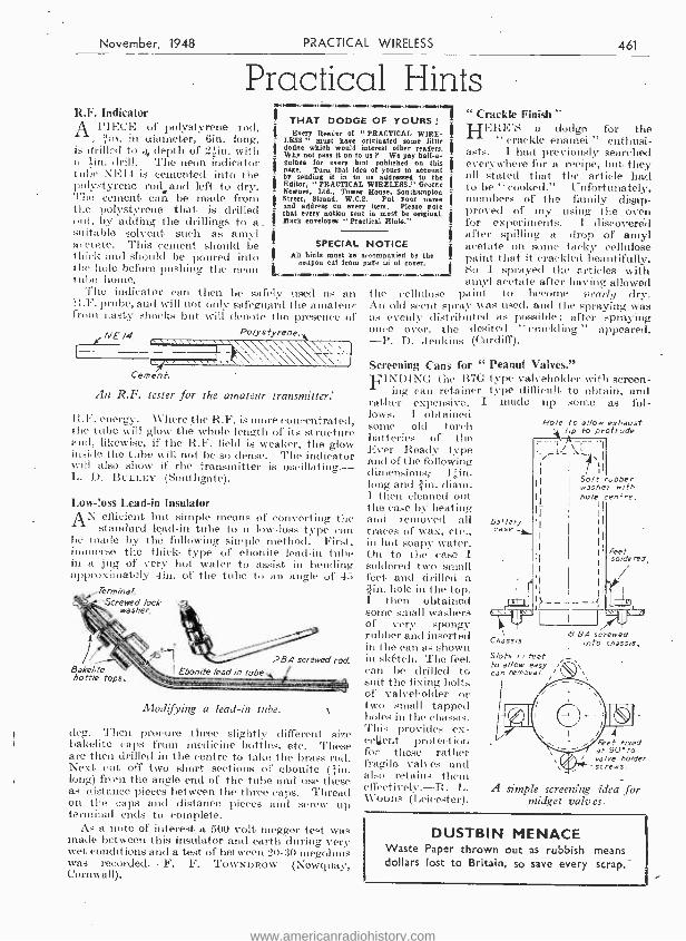
November, 1948 PRACTICAL WIRELESS
Practical Hints R.F. Indicator
A PIECE of polystyrene rod, ¡in. in diameter, Gin. long,
is drilled to 4_ depth of 23in. with a ; in. drill. The neon indicator tube NEI4 is cemented into the polystyrene rod and left to dry. The cement can be made from the polystyrene that, is drilled out, by adding the drillings to a. suitable solvent such as amyl acetate. This cement should be hick and should be poured into
the hole before pushing the neon tube honte.
The indicator can then be safely used as an lt.i'. probe, and will not only safeguard the amateur from nasty shocks but will denote the presence of
ENE l4 Polystyrene
.DINNIMINMI4.1114,.14111111,.MINN,4=1.111
THAT DODGE OF YOURS !
"PRACTICAL WIRE- LESS some little
interest other readers. as We pay half -a
feint published on this o[ yours to aceonn
us addressed to the WIRELESS," George House, Southampton
Pat your name item. Please not
sent in must he original "Practical Fiala."
NOTICE aecompnnied by the page üi of cover.
Every Reader o[ LESS " must bare e dodge which would s. Why not pass it on guinea for every L is page. Turn that idea t by sending it in to e Editor, "PRACTIC e Newnes, Ltd., Towe n Street, Strand, W.0 e and address on every e that every notion se Mark envelopes
SPECIAL All hints must be
roupon Cot from
. W.,.M.,. .W ` i9 .
Cement.
An R.F. tester for the amateur transmitter.'
R.F. energy. Where the R.F. is more concentrated, the tube will glow tite whole length of its structure and, likewise, if the R.F. field is weaker, the glow inside the tube will not be so dense. The indicator will also show if the transmitter is oscillating.- - L. D. BULLEY (Southgate). -
Low -'.oss Lead -in Insulator
AN efficient but simple means of converting the standard lead -in tube to a low -loss type can
be made by the following simple method. First, immerse the thick. type of ebonite lead -in tube in a jug of very hot water to assist in bending approximately 4in. of the tube to an angle of 45
Termina /. Screwed lock
washer.
28.4 screwed rod.
Modifying a lead -in tube.
deg. Then procure three slightly different size bakelite caps from medicine bottles, etc. These are then drilled in the centre to take the brass roil. Next cut off two short sections of ebonite (lin. long) fróui the angle end of the tube and use these as distance pieces between the three caps. Thread on the caps and distance pieces and screw up terminal ends to complete.
As a note of interest a 500 volt megger test was made between this insulator and earth during very wet conditions and a test of between 20 -30 megohms was recorded. -F. F. ToWNDROW (Newquay, Cornwall).
i
461
" Crackle Finish " HERE'S a dodge for the
" crackle enamel " enthusi- asts. 1 had previously searched everywhere for a recipe, but they all stated that the article had to be "cooked." Unfortunately, members of the family disap- proved of my using the oven for experiments. I discovered after spilling a drop of amyl acetate on some tacky cellulose paint that it crackled beautifully. So I sprayed the articles with amyl acetate after having allowed
the cellulose paint to become wail dry. An old scent spray was used, and the spraying was as evenly distributed as possible; after spraying once over, the desired "crackling" appeared. -P. D. Jenkins (Cardiff).
Screening Cans for " FINDING the B70
ing can retainer rather expensive, I lows. I obtained some old torch batteries of the Ever Ready type and of the following dimensions, I gin. long and /in. diam. I then cleaned out the case by heating and removed all traces of wax, etc., in hot soapy water. On to the case I soldered two small feet and drilled a
hole in the top. I then obtained some small washers of very spongy rubber and inserted - in the can as shown in skétch. The feet can be drilled to suit the fixing bolts of valveholder or t small tapped
,Ics in the chassis. This provides ex- ceuent protection for these rather fragile valves and also retains them effectively.-R. L. 1V000s (Leicester).
Peanut Valves." type valveholder with screen - type difficult to obtain, and
macle up some as fol-
Battery case
Ho /e to al /ow exhaust tip to protrude
I ` t 1
1
Soft rubber washer with
II ho /e centre.
I I
Feet so /de red,
Chassis
S /ots in feet to al /ow easy can removal.
r
B. BA. screwed into chassis.
Feet fused at 90° to valve holder screws.
A simple screening idea for midget valves.
DUSTBIN MENACE Waste Paper thrown out as rubbish means dollars lost to Britain, so save every scrap.
www.americanradiohistory.com

462 PRACTICAL WIRELESS November, 1948
111.0 .1. NM. MINN 111141114111111 MEW MINN 10111.1.M. .100.,1.,1.1=1.011111.vim., 1.m., ,fml.,,,,_,.,_,.11=
IN designing the portable about to be described, the object was to produce a compact and com- pletely self -contained battery set, capable of
giving moderate reception of the Light and Home Service programmes, and containing only standard size components usually to 'be found in most spares boxes.
It was found, with the overall size contemplated, that only two standard sized valves could be accommodated. Whilst a conventional two -valve arrangement of detector with reaction, followed by a stage of audit) amplification, might, with careful design, give the desired results for a small room, one stage of radio -frequency amplification is generally necessary for portables, as the pick -up from a frame aerial- is so small compared with the ordinary single -wire aerial.
The author decided, therefore, to include one
Frame
Bedside Porta A Two -valve Receiver of Sma
By R. L. G.
itself from the old reflex days, when economy in valves was important. In the,present instance we are concerned mow with the saving of space. Other types of frequency- changing valves of the radio -frequency pentode class may be found suitable, but the valve used must have the signal grid connected to the top cap.
The Circuit This is seen in Fig. 1, and as will be noted, apart
from the double use of VI, the circuit follows the conventional
o three -valve arrangement, consist- ing of one stage of radio- frequency amplification, leaky -grid detector and a pentode output stage.
The radio -frequency input sig- nal from the frame aerial, tuned by Cl section of the twin - ganged condenser, is amplified at R.F. in the first section of VI.
An efficient H.F. choke (H.F. choke 1) in the anode circuit of this valve by- passes the H.F. oscillations through a small pre- set condenser C5, to the tuned circuit C2L1, connected via condenser C4 to the grid of the second section of V 1. C4 and R 1 constitute the normal recti- fying functions. Reaction effect is obtained by L2 and variable condenser C6. C7 is a small by- pass condenser for stray R.F. cur- rants that may pass H.F. choke 2.
C3
HFC. / H.T+/
6015-00--
V/
RI L2
./
= T/
T Ganged
Fig. 1.- Theoretical circuit of the Portable Two. may be seen ins' the list below.
stage of radio -frequency amplification, by making use of a double valve, of the triode -hexode class, using its two sections to provide the radio -frequency stage and the detector stage of the set, and following this by a pentode output stage. Thus, with only two valves, results comparing favourably with a three -valve layout are obtained.
It might be as well to point out, at this stage, that this is not one of the one -time popular ̀ ` Reflex " arrangements. In this system, the single valve was made to do the work of two, by feeding back the rectified audio current to the H.F. valve for ampli- fication at audio frequency. The scheme adopted in this set is somewhat different and definitely more stable in operation.
The H.2 triode -hexode valve used is, of course, normal used as a frequency- changing valve in superhets, and has an H.F. section and oscillator section. The first is used in its normal manner, whilst the oscillator section is used as a normal leaky -grid detector stage. The author does not claim originality for this feature, which has been quite well tried and, of course, really introduced
LS V2
Component values
LIST OF COMPONEN'. One twin ganged tuning condenser .0005 pF with ,
trimmers, Cl, C2. One reaction condenser, .0003 pF solid dielectric
type, C6. C3 -0.1 pF 1 Tubular paper type C4 -.0003 pF f (non- inductive type). C5- Pre -set type .50 pF. C7 -R.F. by -pass .100 pF. R1-2 megohms (i watt). R2- 15,000 ohms (I watt). R3 -1,000 ohms (4- watt). Three all -wave H.F. chokes (Eddystone No. 1,066). One small Audio transformer, maximum height tin. One 7 -pin
for VI. chassis -mounting type valveholder
One 5 -pin for V2.
chassis -mounting type valveholder
One 4 -pin chassis- mounting type valveholder for coil.
Two stout brass brackets for fixing coil. One on -off switch. One fuse holder with fuse.
AMIN. ...MEW( NW. 1 =111_11... 11_.14=111_1 1./.1MINHIMMIMMWMIMM1110.1111.111711111.1.0041110111141411,. N11.111.
www.americanradiohistory.com

November, 1948 ¿RACTICAL WIRELESS 463
41.1114.11111114.
bye Two Dimensions
The rectified signal is then passed onto the grid of the pentode output valve V2 via an audio transformer T1. R3, a grid stopper, acts as a final choke to any R.F. currents that may be present in Ti.
H.T.+1 supplies the screen voltage to VI ; C3 being the norm&l R.F. by -pass condenser, whilst H.T. -}-2 supplies the anodes of both valves. The author found' it unnecessary to include a de- coupling resistance and condenser in series with the primary of TI, but this might be incorporated should any instability be experi- enced. The value of such a resistance should not however exceed 5,000 ohms, or the anode voltage will be reduced too much for quality results.
.MIMP,1111.11,1_,14/M.41111IMMI.0,, ,11.10_1111,_,1__,NE1.411
TrimmeAs
Mu / /ard T H.2 Serving As Dual R F Amplifier
Twin Ganged And Detector
Tuning \l
Condenser
(assn 1101
,, \ \ \' o uflard TH2
I
M.C.Speaker With Matching Transformer
Mullard PM 22 A Output Pentode
iI;"-'"L' I Framed,..n Aerial e
Tag Board
Aluminium Chassis
Brass - Bracket For Coil Ho /der
Detector Coil With Internal Reaction Coil
,\ S P/atfonn
w 1 Ij
HF Choke 1 ft ti Screen.
HF Choke 2 Fuse
Battery Tag Board
41 Plywood End Pieces
Fig. 2. -A general view of the completed receiver out of its cabinet. with all main parts identified.
The pentode output valve is arranged on the extreme right. The miniature moving -coil speaker, complete with matching transformer, is mounted on a raised metal platform fixed to the chassis immediately between the two valves. This plat- form was found necessary to allow the speaker to be set back level with the front edge of the chassis. As speakers vary in size and design, it is possible
General Layout of Chassis This can be clearly seen in the two drawings
Fig. 2 and Fig. 3. Fig. 2 shpws the complete set, as viewed from
the rear. TIT twin -ganged tuning condenser is seen on the extreme left and the detector and reac- tion coil immediately ,below it, under the chassis. The T.H.2 valve is adjacent to these and its top grid connection allows short wires to frame aerial tag board and to the front section of the ganged tuning condenser.
AND MATERIALS ne 7 -point teg board for battery connections. ne 2 -point tag board for frame connections. ne Mullard TH2 or equivalent. ne Mullard PM22A or equivalent. ne small size moving -coil speaker with matching transformer, maximim size 5in. diameter. ne 8- ribbed coil former 1 in diameter. 4 -pin. n. diameter paxolin tubing, 1.'iin. long (reaction coil). [z frame aerial wire or reel of 22 D.C.C. copper Awire. -
ieet of aluminium for chassis and sub -panels. ply for casing of set and frame aerial. yrdwood for outer case. rather strap and brackets. rte tuning knob, 2in. diameter. se tuning knob (reaction), lein. diameter. andard H.T.. battery 120 volts, with tappings. se 9 -volt grid -bias battery. ne Varley dry accumulator, V20. mnecting wire, sleeving, flex, setscrews, etc.
Fig. 3. -Front view of the chassis, with main dimensions.
K,41=4.00.,o,1,1.11, 141.4 .mn.O.M.111.111 01,_<4,IIMM.11_1,.11N,IIMPINIIIN,41.1M,
www.americanradiohistory.com
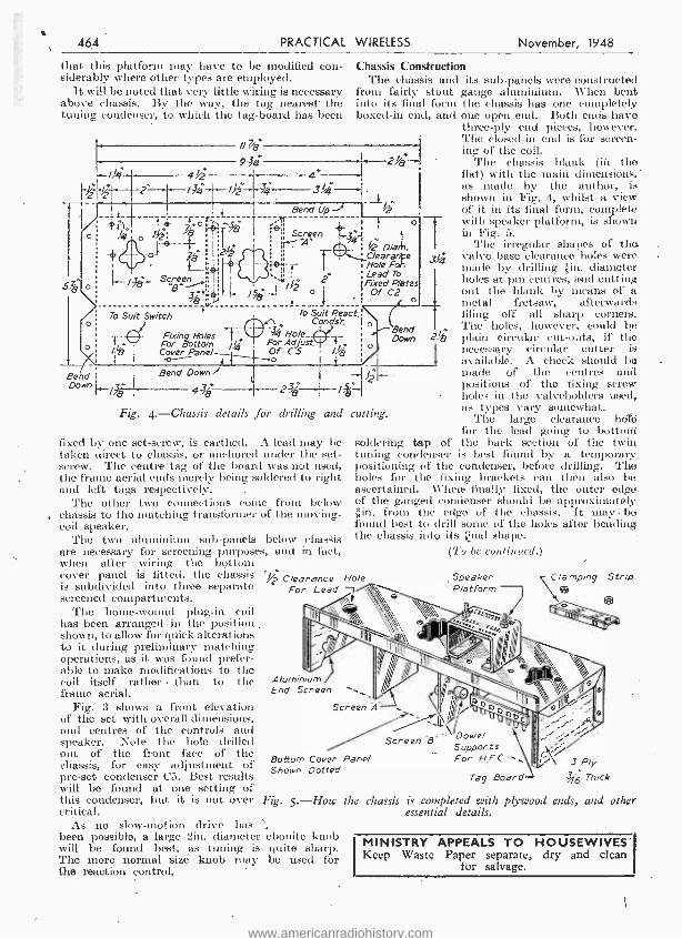
464 PRACTICAL WIRELESS. November, 1948
that this platform may have to be modified con- siderably where other types are employed.
It will be noted that very little wiring is necessary above chassis: By the way, the tag nearest' the tuning condenser, to which the tag -board has been
Sf1, I o
Chassis Construction The chassis and
from fairly stout into its final form boxed -in end, and
f/43+
4ii 93i4
4° i 2f6
2.= In_ /y`I 4 3 i ---1 f L _ I
Bend Up -% I .;--__+--ö, t'lr ' T
J {
i Screen ..i ! o - T :
A' L4 ; //2 Oiañi. ;'g 4.C/earare
1..._,46....1 i__ ,' 1 1 Hole Fol 3c?." 11 2. 'Fixed Plates J o I , Of C2 3 / } o
To Suit Switch
Fixing Ho /es $ Hole_ For Bottom /k 1 For Adjust. Coves er Panel
} Of CS
Bend Bend Down, Down
/
4.36+
To Suit React.'
- -Bend Down T ;
I + /
f'- I 2e / Fig. 4.- Chassis details for drilling and cutting.
fixed by one set- screw, is earthed. A -lead may be taken direct to chassis, or anchored under the set- screw. The centre tag of the board was not used, the frame aerial ends merely being soldered to right and left tags respectively.
The other two connections come from below chassis to the matching transformer of the moving - coil speaker.
The two aluminium sub -panels below chassis are necessary for screening purposes, and in fact, when after wiring the bottom cover panel- is fitted, the chassis is subdivided into three separate screened compartments.
The home-wound plug -in coil has been arranged in the position shown, to allow for quick alterations to it during preliminary matching operations, as it was found prefer- able to make modifications to the coil itself rather - than to the frame aerial.
Fig. 3 shows a front elevation of the set with overall dimensions, and centres of the controls and speaker. Dote the hole drilled out of the front face of the chassis, for easy adjustment of pre -set condenser C5. Best results will be found at one setting of this condenser, but it is not over critical.
As no slow- motion drive has been possible, a large 2M. diameter will be found best, as tuning is The more normal size knob may the reaction control.
3d4
24;
soldering tap of tuning condenser is best found by a temporary positioning of the condenser, before drilling. The holes for the fixing brackets can then also be ascertained. When. finally fixed, the outer edge of the ganged condenser should be approximately -in. from the edge of the chassis. It maybe found best to drill seine of the holes after bending the chassis into its final shape.
(To be continued.)
its sub -panels were constructed gauge aluminium. When bent the chassis has one completely one open end. Both ends have three -ply end pieces, however. The closed -in end is for screen- ing of the coil.
The chassis blank (iii the fiat) with the main dimensions, as made by the author, is shown in Fig. 4, whilst a view of it in its final form, complete with speaker platform, is shown in Fig. 5.
Thé irregular shapes of the valve base clearance holes were macle by drilling ¡in. diameter holes at pin centres, and cutting out the blank by means of a metal fretsaw, afterwards filing off all sharp corners. The holes, however, could be plain circular cut -outs, if the necessary circular cutter is available. A check should be made of the centres and positions of the fixing screw holes in the valveholders used, as types vary somewhat.
The large clearance hölé for the lead going to bottoiti the back section of the twin-
%2 Clearance Ho /e For Lead
Speaker 'Platform
C Strip
631
Aluminium End Screen
Screen 'A
Bottom Cover Panel Shown Dotted
Screen B' Dowel Supports For H.FC
Tag Board 3 Ply
1'6 Thick
Fig. 5. How the chassis is completed with plywood ends, and other essential details.
ebonite knob quite sharp. be used for
MINISTRY APPEALS TO HOUSEWIVES Keep Waste Paper separate, dry and clean
for salvage.
www.americanradiohistory.com
November, 1948 PRACTICAL WIRELESS 465
Radio Amateurs Exam inattons The 1948 Test Paper and a Report on the Results`
IN order that prospective transmitting amateurs may gain some idea of the standard required by the G.P.O. Examinations, we again give
the full Test Paper set in May last. The City and Guilds of London Institute have reported on this Examination and their report follows the Paper.
1948 Radio Amateur's Examination :
All questions should he attempted. Use should be made of diagrams where applicable. The maximum possible marks obtainable are affixed to each question.
1. How is a low -power transmitter likely to interfere with broadcast reception ? What steps would you take to prevent such interference ?
(15 marks.) 2. What steps should be taken by the holder
of an amateur transmitting licence to ensure full compliance with the requirement that a full record should be kept of all transmissions ? (15 marks.)
3. Give a brief description of a suitable receiver for the 58.5 to 60 mc/s frequency band, and explain how it works. (15 marks.)
4. How is the input power to the last stage of a transmitter measured ? What is imderstood by the " efficiency of operation " of this stage and how is this connected with the permissible anode dissipation ? (15 marks.)
5. Describe briefly how the ionosphere influences the propagation of radio waves, and how propaga- tion differs between the 1.7 to 2.0 Me /s band and the 58.5 to 60 Mc /s band. (10 marks.)
6. What advantage is gained from using a piezo -electric crystal oscillator in a radio trans- mitter ? Give a diagram of a crystal controlled stage for a short -wave transmitter. (10 marks.)
7. Describe a transmitting aerial suitable for one of the amateur bands, indicating the main features of the design and any directional properties. Illustrate your answer with a diagram. (10 marks.)
8. What is the effect of connecting two capa- citors (a) in series, and (b) in parallel ?
What is the total effective capacitance when four capacitors, each of 100 NJ' are connected in a series- parallel arrangement consisting of two parallel paths, each of which contains two capacitors in series ? (10 marks.)
Report on the Papers The following general report is given on the
papers as a whole and is not necessarily applicable to the work from individual schools.
No. of tCandidates I
No. of Passes
No. of Failures
Percentage of Failures
Home Overseas
687 13
518 Io
169 3
24.6 23.1
Candidates' work in the 1948 Radio Amateurs' Examination, as compared with the previous examinations, was generally of a much higher standard both technically and in the manner in which the questions were answered. It was apparent that more adequate. preparation. had been made for
this year's examination. With very few exceptions, all questions were attempted by the candidates. A report on the questions follows :
Question 1 (transmitter interference) : Fairly well done by most candidates.
Question 2 (log requirements) : Very well done by practically all candidates.
Question 3 (60 Mc /s receiver) : A fair number of the candidates illustrated their answers with excellent diagrams, but the majority handicapped themselves to some extent by using block diagrams, or by describing the converter circuit .without following it up with the succeeding stages.
Question 4 (input power) : The first two parts of the question were very well answered by practically all candidates, but many found the third part of the question, in connection with permissible anode dissipation, difficult to answer.
Question 5 (wave propagation) : Fairly well done by the majority of the candidates. A fair number failed to describe how propagation differs between the 1.7 Mc /s and 60 Mc /s band.
Question 6 (crystal oscillator) Very well done Question 7 (transmitting aerial) by practically Question 8 (calculation) all candidates.
Radio Vans and Farmers WO -WAY radio telephony is playing its part
in helping Scottish farmers get in the harvest in the quickest possible time.
Mr. Daniel Ross, Lanark dealer for Britain's famous Ferguson tractors, has equipped his five service vans and his headquarters with radio so that help may be sent with the least possible delay to any of his 200 to 300 customers who run into trouble with their equipment.
At a time when any hold -up in farming may mean food spoiled, farmers working in the remotest Lanarkshire hill -villages can have help sent to them by radio almost as quickly as if they lived close to large towns.
With a fixed station in Lanark town, Mr. Ross keeps in continuous touch with his service vans as they travel about the country on their routine day's s'ervice work and plots their position on a map in his office. As soon as an S O S is received from a farmer, the nearest service van can be directed to the scene of the hold -up and very often a minor adjustment can be made in a few minutes where, without radio -aid, the farmer might have been inactivated for half a day or more.
Mr. Ross uses Pye equipment for his five mobile and one fixed station and they operate on a fre- quency of 73.275 megacycles. According to the G.P.O., the Simplex single- frequency working equipment is the first of its type to be used by a commercial concern in this country. Output of both the fixed and the mobile stations is 12 watts R.F.
The aerial of the fixed station is 850ft. abova sea level and although there are a good many high hills in the area the fixed transmitter has an average working range of about 25 miles, while from high ground a range of 40 miles has been achieved.
www.americanradiohistory.com
466 PRACTICAL WIRELESS November, 1948
Lundlord and Tenant An Explanation of an Important Act of Great Value to the Small Trader
By A BARRISTER
HAVING regard to the fact that the large majority of traders aro entirely un- acquainted with the valuable rights
conferred on them by The Landlord and Tenant Act 1927, and that literally thousands of pounds are thrown away every year as the result, a brief survey of their position with practical hints as to the measures that they should adopt to protect their interests, may be usefully made.
A classical example of the unfortunate results of such ignorance of the law may be given. A landlord owned a - number of shops, all let under separate leases to different traders. All the leases were due to expire at the same time. Only one of the tenants was aware of his position under the Act. He took the precaution of serving his notice claiming a new loase, in time, and of commencing his proceedings also in time, and obtained very advantageous terms. The other tenants who had - neglected to observe the requirements of the Act were not in a position to bargain with the landlord, and had to choose between accepting the landlord's terms as to rent and otherwise, or vacating the premises where they had built up a very valuable goodwill.
Now the underlying object of the Landlord and Tenant Act 1927 is not to compensate the tenant for the whole of his loss, but merely to the extent of the landlord's gain. Thus a tenant executes improvements to the premises, which result in addition to their letting value when the tenant leaves, and the landlord gets the benefit. What the Act says is that the landlord must com- pensate the tenant for this benefit. Further, the Act enables a tenant to carry out improvements to the premises even against the landlord's wishes. But -and it is here that tenants usually go astray - the Act provides that a certain procedure must be strictly observed by the tenant if he desires to enjoy those statutory benefits.
Goodwill Again, take the caso of goodwill. A trader and his
predecessor in title may have built up a very valuable goodwill by several years' trading. \Vhen the tenant goes the landlord gets the benefit of this goodwill. He can let the premises to another trader at a very much enhanced rental. The newcomer is only too pleased to pay more in return for the advantage of stepping into the shoes of the old tenant and getting the benefit of his custom. Here again time landlord must compensate the .tenant for this goodwill which will remain behind. But what is more, as compensation usually is not good enough for the tenant, he is allowed by the Act in certain circumstances to compel his landlord to grant him a new lease of the premises.
And if a new lease is ordered the landlord can charge only the ordinary market rental value of the premises on the basis of the letting being a first letting. The tenant can be granted a new lease for a further term which, however, may not
exceed 14 years. But here again the Act lays down a strict procedure which must be followed by the tenant. In this respect as well, tenants usually allow the grass to grow under their feet until it is too late. And then they must stand by and see the value of their goodwill pass into the hands of their landlord. '
Qualifying Period Before a tenant can be entitled to compensation
for goodwill or a new lease it is essential that the trade should have been carried on on the premises by the tenant or his predecessors in title for a period of at least 5 years.
Further, it is necessary to show that a substantial portion of the goodwill will remain behind attached to the premises and that in consequence the land- lord will be able to command a higher rent for the
If a tenant can establish these facts he will usually.. be entitled to- a new lease, though, strictly, a new lease cannot be granted unless it is shown that the amount of the compensation recoverable under -
the Act -which is necessarily limited -will not compensate the tenant for the loss of goodwill he will suffer if he has to vacate time premises.
These may be regarded as the substantive con- ditions which nurst be established. But there are, conditions relating to procedure which are also of vital importance. These conditions are really: very simple, but timo and again they are overlooked.:
% 1rat -the Act requires the tenant to do is to serve the landlord with a notice of claim and to servo it within the time limits laid down. If the notice is even a day out of time nothing can be done at all, and all rights will be lost. Whether the claim is for iniprorenieits or for goodwill, or for a new lease, the time limits for the service of the notice of claire are the sanie.
Where the tenancy expires automatically $y efftuxion of time, the notice must be served at least 12 months before the tenancy is due to expire; where the tenancy is determined by a notice to'
the notice of 'claim must be served within one mouth from the date of time receipt by thé' tenant of the notice to quit.
Furthermore, if a new lease is being claimed' proceedings must be commenced at least nine months- before the tenancy is due to end, or if a notice tó quit hasrbeen served, then within two months of the receipt of the notice to quit.
MASTERING MORSE By the Editor of Practical - Wireless"
3rd Edition.
1/- or 1/2 by post, from George Newnes, Ltd., Tower House, Southampton Street, Strand, W.C.2.
www.americanradiohistory.com

November, 1948 PRACTICAL WIRELESS 467
Amateur T he Care
Transmitting Vaves and Maintenance of Ex- Service Valves
By E. G. BULLEY
MANYMANY amateur transmitters are operating for first time, and no doubt, the newcomer
to transmitting has purchased at some time or other surplus Government transmitting valves which are suitable for the amateur station. This article is written to explain how with careful handling, in actual operation, these vanes can be made to last quite a long time.
The life of the valve is perhaps the most important factor to the amateur, the reason being that these valves are usually fairly expensive to replace, al- though every effort is being made by the manufac- turers to bring them well within the amateur's pocket.
Radio transmitting valves although of rugged and robust construction are in some respects unlike the receiving types, because they require a certain amount of care when being installed in any equip- ment. The bulb, for instance, becomes very hot during the continuous operation of the valve. It is therefore essential to install the valve in a well ventilated position so as to allow for a free circula- tion of air around the bulb. Leads taken to the various electrodes must be suitably screened and large enough to handle the R.F. energy that is flowing in the circuit, otherwise excessive heating will result in the leads, which will eventually be conducted to the valve seal and result in its destruction. These leads should not on any account be allowed to come into contact with the glass bulb during the operation of the valve, as metallic objects touching hot glass may cause the glass to crack.
Heaters or Filaments The emitting electrodes in transmitting valves
are usually directly heated, although there are many types that employ indirectly -heated cathodes. However, valves which are intended for amateur use are low or medium power types. These use as the emitting electrode either a thoriated tungsten filament or an oxide coated cathode, the former type being directly heated, whereas the latter is indirectly heated. Earlier types of amateur, transmitting valves did employ pure tungsten filaments, but this type of filament is now only used in high -power types such as those used in commercial broadcasting or industrial equipments. But to enable the reader to appreciate fully the actual filament characteristics, it will be necessary to review all three types, so that whatever typo of filament is encountered the life of the valve can be safeguarded.
Pure tungsten filaments can be within certain limits slightly overrun, but it is inadvisable to do this as it will dnly shorten the life of the valve. On the other hand. however, if the filament is underrun a lower filament emission will result,. due to the lower operating temperature of the filament, but a much /anger life can be expected.
This, however, is only possible if the valve in ques- tion is operated at a reduced frequency at which it is designed to operate and where full emission is not required.
In the case of thoriated tungsten filaments, it is essential that the filament voltage applied most not vary within plus or minus 5 per cent. of its rated value, otherwise, if the voltage is too high, the thoria content of the wire will evaporate from the filament surface at a much faster rate than the thoria content can diffuse to the filament surface. This will result in a large drop in the filament emission, in fact, it will eventually be equal to that of pure tungsten because the filament has become stripped of the thoria content.
A Warning Thoriated filaments should not be underrun,
because loss of emission will still result and the life of the valve would not be increased as in the case of pure tungsten filaments.
In the actual circuit wherein a thoriated tungsten or oxide coated Cathode valve is used, it is advisable to connect a suitable voltmeter across the filament terminals ; this will ensure that the filament voltage is not reduced or exceeded. Idle periods of trans- mission card deteriorate the valve or valves, so it is advisable that the filament should be operated at its full rating without any other electrode potentials being applied.
Transmitting valves of the thoriated filament type can be operated from an X.C. ' or D.C. supply. The latter is sometimes used to avoid hum, but the former is mainly used because of the convenience.
Oxide -coated Cathode The last emitter to consider is the oxide -coated
cathode. Care must be taken when operating this type because, should the cathode be overrun, cathodic sputtering may result and the adjacent electrodes become contaminated with the coating material. This contamination will cause emission to take place from the affected electrodes and it is essential that this be avoided at all costs.
The next consideration is that of the maximum anode dissipation. This rating is an indication of tile maximum power that can be safely dissipated by the anode. Failure to keep to or within the specified value, will affect the life of the valve and in some cases destroy it.
The maximum dissipation rating can be exceeded if the anode current rises. This can sometimes be traced to the failure of the grid bias. This bias is usually obtained from a D.C. supply, grid leak or by means of a resistor in the cathode circuit. The grid leak method is not advisable, because should the driver stage fail, the valve will auto- matically lose its bias voltage and so /'result in the anode drawing excessive current.
To prevent the anode dissipation from being
www.americanradiohistory.com
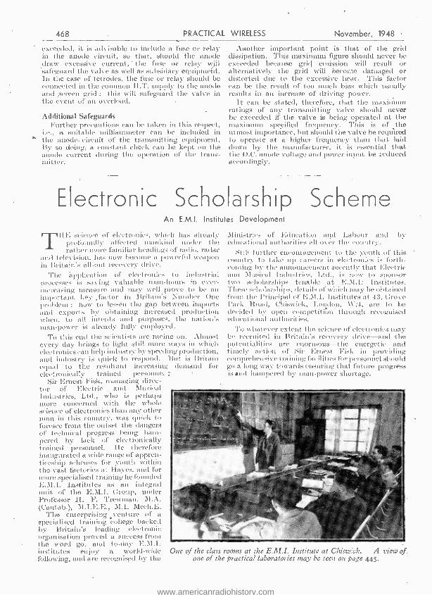
468 PRACTICAL WIRELESS November, 1948
exceeded, it is advisable to include a fuse or relay in the anode circuit, so that, should the anode draw excessive current, the fuse or relay a }Il
- safeguard the valve as well as subsidary equipment. In the case of tetrodes, the fuse or relay should be connected in the common H.T. supply to the anode and screen grid ; this will safeguard the valve in the event of an overload.
Additional Safeguards Further precautions can be taken in this respect,
i.e., a suitable milliammeter call be included in the anode. circuit of the transmitting equipment. By so doing, a constant check can be kept on the anode current during the operation of the trans- mitter.
Another important point is that of the grid dissipation. This maximum figure should never be exceeded because grid emission will result or alternatively the grid will become damaged or distorted due to the excessive heat. This factor can be the result of too much bias which usually results in an increase of driving power.
It can be stated, therefore, that the maximum ratings of any transmitting valve should never be exceeded if the valve is being operated at the maximum specified frequency. This is of the utmost importance, but should the valve be required to operate at a higher frequency than that laid down by the manufacturer, it is essential that the D.G. anode voltage and power input be reduced accordingly.
Electronic Scholarship Scheme An E.M.I. Institutes Development
THE science of electronics, which has already profoundly affected mankind under the rather more familiar headings of radio, radar
and television, has now become a powerful weapon in Britain's all -out recovery- drive.
The 'application of electronics to industrial processes is saving valuable man -hours in ever - increasing measure and may well prove to be an important key .factor in Britain's Number One problem : how to lessen the gap between imports and exports by obtaining increased production when, to all intents and purposes, the nation's than -power is already fully employed.
To this end the scientists are racing on. Almost every day brings to light still more ways in which electronics can help industry by speeding production, and industry is quick to respond. But is Britain equal to the resultant increasing demand for electronically trained personnel:
Sir Ernest Fisk, managing direc- tor of Electric and Musical Industries, Ltd., who is perhaps more concerned with the whole science of electronics titan any other man in this country, was quick to foresee front the outset the dangers of technical progress being ham- pered by lack of electronically trained personnel. He tltereforc inaugurated a wide range of appren- ticeship schemes for youth within the vast factories at Hayes, and for more specialised training he founder I
E.BI.i. Institutes as an integral unit of the E.I.I. Group, under Professor H. F. Trewman, N..N. (Cantab.), M.I.E.E., M.I. Mech.E.
The enterprising venture of a specialised training college backed by Britain's leading electronic organisation proved a success from the word go, and to -day E.M.1. institutes enjoy a world -wide One of the class following, and are recognised, by the one of the
Ministries of Education and Labour and by educational authorities all over the country.
Still further encouragement to the youth of this country to take up careers in electronics is.forth- coming by the announcement recently- that Electric and Musical industries. Ltd., is now to sponsor to t slrolatships tenable at E.M.I: Institutes. These scholarships, details of which may be obtained from the Principal of E.M.I. Institutes at 43, Grove Park Road, Chiswick, London, W:4, are to be decided by open eompetitiún through recognised educational authorities.
To whatever extent the science of electronics may be recruited in Britain's recovery drive -and Hie potentialities are enormous-the energetic and timely action of Sir Ernest Fisk in providing comprehensive training facilities for personnel should go a long way towards ensuring that future progress is tut (tampered by man -power shortage.
rooms at the E.M.I. Institute at Chiswick. A view of practical laboratories may be seen on page 445.
www.americanradiohistory.com

November, 1948 PRACTICAL WIRELESS 469
Underneath the Dipole Television Pick -ups and Reflections. By THE SCANNER"
THE Olympic Gamos proved to be a triumph for British television if for nothing else !
The British lack of success in the arena was fully reported in our utility size newspapers, and on the films and radio, but nowhere was the atmosphere of the historic event conveyed so well as it was via television. The new supersensitive cameras transmitted pictures of fine definition and must have compared most favourably with the American image -orthicon cameras about which we have heard so much. Special praise is due to the operators of these cameras and also to the producers or editors, whose selection of shots was most expertly carried out, making the most of a wealth of material. It is the slick editorial handling of such transmissions, the timing of the " cuts " from long shot to close -up, the use of panoramic shots and audience reactions, married to a really " live " commentary, which combine to give a polished entity. This was indeed television at its best.
Camera Angles The choice of camera angles is not always so
successful in the studio transmissions. Too often does one see close -ups of dancers with their feet out of picture, or shots of actors with candelabra or other " busy " pieces of scenery apparently growing out of their heads. Part of the trouble is due to the arrangement of the scenery and stage properties. It is far better from the viewers' point of view, for instance, for variety artistes to do their acts in front of curtains rather than the hackneyed garden trellis -works so often inflicted upon us. Apart from their phoney ugliness, they form a background which tires the eye and makes fantastic non- linear shapes near the edge of the cathode ray tube. But curtains can be equally distracting if they are vividly patterned. A particularly bad example was seen recently in a
Crossword " feature, in which a chequered curtain of high contrast appeared to give a deathly pallor to the faces of Harold Warrender and the other artistes. The choice of camera angles for dancing turns and musical comedy shows is frequently faulty. Apart from the cutting out of feet already mentioned, an equally annoying angle is the high -angle long shot, which foreshortens the artistes' legs and turns them into grotesque shapes. Curiously enough, low angle shots, with the camera on the floor, gives a type of distortion which is usually acceptable and sometimes highly effective. These are points . which seem to be much more appreciated by the dramatic producers, who do not often err in this respect.
High Comedy Drawing -room and evening -dress comedies, when
put on the films, have always required the sure touch of a director who is also a first-class technician. Poor technical qualities and lack of smoothness and polish, which might be tolerable for a melodrama or a slap -stick comedy, are quite unacceptable in
the presentation of the boiled -shirt delicacies of the cinema. The same applies to television. W. Somerset Maugham's light and frothy comedy " The Unattainable " was put over on television with a smoothness that was reminiscent of the svelte Lubitch films of 10 years ago. The producer, Stephen Harrison, tried a technique more on film lines than other B.B.C. producers have been following lately, and his use of multiple cameras in static positions with 'very little camera tracking was completely successful. This success was the result of Harrison's most expert handling of the switches which changed over from one camera to another ; the timing of the " cuts " was exact, and the choice of camera angles did not require the viewer to perform mental acrobatics in order to remember the geography of the setting. This was television production of the straightforward type at its best. The playing by the artistes was exquisite, particularly by Gillian Lind, Marian Spencer and Ellen Pollock, and Somerset Maugham's witty dialogue lost not one of its " wisecracks," to use a horrible modernism !
The Way Ahead So the 405 line standard is to stay with us for
many years ! At last, the real and definite decision will enable manufacturers to lay down plant with confidence, to produce more and more television receivers at -we hope -a less and less price. The next move is now with the B.B.C., who will be pressed to open television transmitting stations in Birmingham, Manchester and Glasgow as soon as possible. That is probably the order in which these stations will be completed, with the Birming- ham station in full operation by the autumn of 1949. I must say that it seems a very long time for Birmingham to have to wait, not to mention further long time lapses before Manchester and Glasgow can operate. But anyone in the radio or electrical business knows the terrible delays in the delivery of switchgear, transformers and other components, and the difficulty of making do with second -hand " just -as- goods." But there is also the question of the radio or landline link to be considered, since the majority of programmes will be transmitted from London. The costs will be tremendous, but the B.B.C. will be rewarded by colossal increases in the number of television licences issued. I can't help thinking that the photographic recording of television will make rapid progress, however, and become the principal means of re- transmission at provincial television transmitters and for "reissues" from London.
We already know that rapid strides have been made in the scanning of cine film, and that very great improvements in the television transmission of film will be made at the Alexandra Palace within the next few weeks. I have myself seen large- screen reproduction of 35 mm. cine film on " closed circuit " and also on an experimental wireless link which was of far greater definition than the present
www.americanradiohistory.com
470 PRACTICAL WIRELESS November, 1948
average studio transmission from the Alexandra' Palace. The improvement in quality was achieved on the 405 line standard.
Temporary Stations? The photographic recording of all television
material is a natural development. I venture to suggest that it would prove a most valuable form of export, bringing in dollars and circulating abroad the British point of view. Film records of our best television plays should certainly command a good price in the American television field, with its dozens of transmitters. Such film records could also be used in one or two provincial areas in Britain, transmitted from temporary or mobile transmitters of small power, pending the completion of the large permanent transmitters. The successes of the small relay stations at Leeds, Hull, Plymouth and Edinburgh in the early clays of broadcasting may have their equivalent in these television days. After all, mobile transmitters have been used for Continental demonstrations of the British system.
I think it was in 1924 that no fewer than eleven 200 -watt relay stations were erected in less than twelve months in such places as Plymouth, Edin- burgh, Dundee, Liverpool, Leeds, Bradford, Hull, Nottingham, Swansea, Sheffield and Stoke -on- Trent. A simple form of transmitter was designed by the B.B.C. Research Department, then under Capt. A. G. D. West (who is now the technical chief of Cinema Television, Ltd.); and each station had its own broadcasting studio in addition to a landline connection with London station. The aerials were,
in most cases, suspended from factory chimneys, and those at Dundee, Leeds, Liverpool and Nottingham gave particularly good results owing to their height ano situation. Hull and Swansea aerials were suspen ed upon masts 100ft. high and were less' satisfactory. The Edinburgh transmitter was situated in the University and was notable for its counterpoise, necessary on account of earthing difficulties. Most of these sites, and similar ones in Glasgow and Manchester, would lend themselves to a scheme of temporary television transmitters of limited range. And what a wonderful site could be made at the top of the Blackpool Tower !
In 1924, these makeshift little transmitters and their studios were put into operation at the rate of one per month, by a company called " The British Broadcasting. Company Limited," which was a private company, the share capital of which was largely owned by several of the leading electrical companies. Quick decisions were made by its managing director, J. C. W. Reith, and its leading engineers, Eckersley, Ashbridge and West. With all the goodwill in the world, it would be quite impossible for the present committee- ridden B.B.C. to make quick decisions, or to embark upon any policy that has not been thoroughly chewed over by some outside committee of non -experts. We must not forget that 1924 was before the days of " forms in triplicate." I have an idea that some of these pink forms were cleverly evaded by the men who accomplished the magnificent television results of the Olympic Gaines on apparatus which was partly improvised.
Southend Radar Installation. Details of the Recently
\RINE INSTRUMENTS, LTD., have in- stalled, at the end of Southend Pier, a Kelvin- Hughes Marine Radar installation
v,hich was formerly opened by the Mayor of Southend, Alderman S. F. Johnson, on Monday, August 23rd.
The new radar station will be used by the makers for testing marine radar equipment and carrying out research in radar technique under conditions which closely approximate to sea -going conditions, the set being a.mile- and -a -third from the shore and adjacent to busy shipping lanes.
In addition, training facilities will be provided for radar engineers and ship's officers in the operation of marine radar equipment.
An opportunity has also been provided for mem- bers of the public to see radar in operation for the first time under service conditions. A repeater console has been fitted on the. pier at deck level for the use of visitors.
The set used at Southend is the standard marine unit produced by the makers, which has recently been granted the type -approved certificate of the Ministry of Transport, and it meets the stringent performance standard which is demanded by the Ministry. Objects at any distance in a horizontal plane- -from 40 yds. to 27 miles can be picked up on the indicator.
Installed Navigation Aid
Aerial System The radiator comprises a simple cheese reflector
of 5ft. horizontal and 4in. vertical aperture excited by a horn coupled via a waveguide to the trans- mitter. (1) Horizontal beamwidth Measured as the full
1.5 deg. (2) Vertical beamwidth ange to flac half-power
27 deg. points, i.e., 6 db down.
Side lobes are less than 5 per cent. of the main beam amplitude.
The scan is of continuous $60 deg. rotation, generally clockwise, at a speed of 30 r.p.m.
The aerial system is not position stabilised, but the wide vertical beamwidth provides adequately for roll up to -x-10 deg.
A thermostatically controlled heater is included in the aerial head to overcome icing troubles.
Display A9in. magnetic cathode ray tube, with a double
screen of long afterglow, isprovided (VCR 516 or CV 262 or a fluoride equivalent). The time base generators provide a sweep of from 1 to 27 miles full scale deflection, variable continuously from 1
to 5 miles, and then by switch to 9 or 27 miles. The auxiliary display used for chart comparison
www.americanradiohistory.com
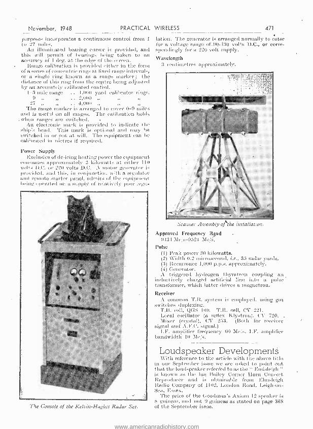
November, 1948 PRACTICAL WIRELESS 471
purposes incorporates a continuous control from 1
to 27 miles. An illuminated bearing cursor is provided, and
this will permit of bearings being taken to an accuracy of 1 deg. at the edge of the screen.
Range calibration is provided either in the form of a series of concentric rings at fixed rango intervals, or a single. ring known as a range marker ; the distance of this ring from the centre being adjusted by an accurately calibrated control..
1 -5 mile range .. 1,000 yard calibrator rings. 9 .. 2,000
27 4,000 The range marker is arranged to cover 0 -9 miles
and is useful on all ranges. The calibration holds when ranges are switched. -
An electronic mark is provided to indicate the ship's head. This mark is optional and may be switched in or out at will. The equipment can be calibrated in Metres if required.
Power Supply Exclusive of de -icing heating power the equipment
consumes approximately 2 kilowatts at either 110 volts D.C. or 220 volts D.C. A motor generator is provided, and this, in conjunction with a regulator and remote starter panel, admits of the equipment being operated on a supply of relatively poor reps.
The Console of the Kelvin- Hughes Radar Set.
lation. The generator is arranged normally to cater for a voltage range of.90 -130 volts D.C., or corre- spondingly for a 220 -volt supply.
Wavelength 3 centimetres approximately.
Scanner Ac.einbly of'`the installation.
Approved Frequency Band -
9434 -Me,'s -9524 Mc /s. Pulse
(1) Peak power 30 kilowatts. (2) Width 0.2 microsecond, i.e., 35 radar yards. (3) Recurrence 1,000 p.p.s. approximately. (4) Generator. A triggered hydrogen thyratron coupling an
inductively charged artificial line into a pulse transformer, which latter drives a magnetron.
Receiver A common T.R. system is employed, using gas
switches duplexing. T.B. cell, (CGS 100. T.R. cell, CV 221. Local oscillator (a reflex Klystron), CV 720. Mixer (crystal), CV 253. (Both for receiver
signal and A.F.C. signal.) LF. amplifier frequency 60 Me/s. I.F. amplifier
bandwidth 10 Mc /s.
Loudspeaker Developments With reference to the article with the above title
in our September issue we are asked to point out that the loudspeaker referred to as the " Endsleigh " is known as the Ian Bailey Corner Horn Concert Reproducer and is obtainable from Elmsleigh Radio Company of 1102, London Road, Leigh -on- Sea, Essex.
The price of the Gooclman's Axiom 12 speaker is S guineas, and not 9 guineas as stated on page 368 of the September issue.
www.americanradiohistory.com

472 PRACTICAL WIRELESS November, 1948
Trade Notes New Taylor Instruments
Tli E tendency with modern measuring instruments is for a reduction in size. At the same time
there is a demand for long and clear scales. These two apparently incompatible features have been effectively achieved in the new Taylor Series 415 sector shape instruments. Occupying little space (four instruments can be mounted in a Ift. squaw), modern in design, and in attractive moulded camas, they are ideal for charging boards, control panels, electronic and electro- medical equipment.
These instruments are now available as moving coil ammeters in ranges from 0 -10 micro -amps. upwards ; as moving coil voltmeters from 0 -5
The new Taylor sector-meter.
milli -volts upwards ; as rectifier ammeters from o -25 microamps. upwards, and as rectifier voltmeters 0 -1 volts upwards.
Thermocouple instruments are also available, and shortly the series will be extended to cover moving iron ranges.
Superhet Permeability Tuning Unit
THE Weymouth Radio Manufactur- ing Company have produced a
complete tuning unit for supet-het operation (intermediate frequency 470 kc %s.) covering wavebands of 200 -540 and 1,000 -2,000 metres, in which tuning is effected by the cam follower system giving 360 degree rotation of the spindle.
Wave change switching is automat ic- ally ca h operated at zero and 18n degrees. thus allowinó the use of air
aeroplane " type scale in which the top half is devoted to the medium wave and lower half to the long wave- band. (A suitable scale can be sup- plied by the makers:) -
Extremely high sensitivity and selectivity is attained by the use of this unit, being in no small measure clue to the very favourable L/C ratio
employed. The xiunrm capacity across the tuned cirktit is l:,o pe'. and therefore, while the performance at the high frequency ends of the two bands is exceedingly good, it improves very considerably towards the low frequency end by virtue of the greater insertion of tuning cores and consequent increase of inductance, giving an even more favourable L/C ratio. This fact is of particular interest in view of the Third programme being only receivable on 524 metres in many areas.
Tracking is extremely satisfactory and has proved, in practice, to be even better than that usually obtained with the normal condenser tuning system. The standard unit is supplied complete with basic circuit diagram for either mains or battery operation, and it is noteworthy that an excellent performance is obtainable with H.T. supply voltages as low as 90 volts by using Mullard D152 or equivalent frequency changers.
The retail price is 45s.. and the makers inform us that the delivery position has very considerably improved and the units are now available front stock.
Two New Philips Television Models pmu,PS ELECTRICAL, LTD., announce. flip
introduction of two new television receivers. They are the Table Model 383A (illustrated below), and the Console Model 663A.
l\lodel 383A is the new table model for vision and sound only. The horizontal -style cabinet is carried out in polished mahogany, giving this receiver a particularly distinctive and attractive appearance. It incorporates a gin. tubo and the picture quality is of a very high standard.
The Console Model 663A is a handsome piece of furniture in mahogany. The specification includes a 12in. tube, and in addition a very efficient seven- valve all-wave broadcast receiver giving extremely good reception on the long, medium and short wavebands, with first -class quality of reproduction. The prices are :- Model 383A. £61 14s. 5d. Model 66:1 A. £ l 10 4s. 4d.
Philips' new table model television receiver.
www.americanradiohistory.com
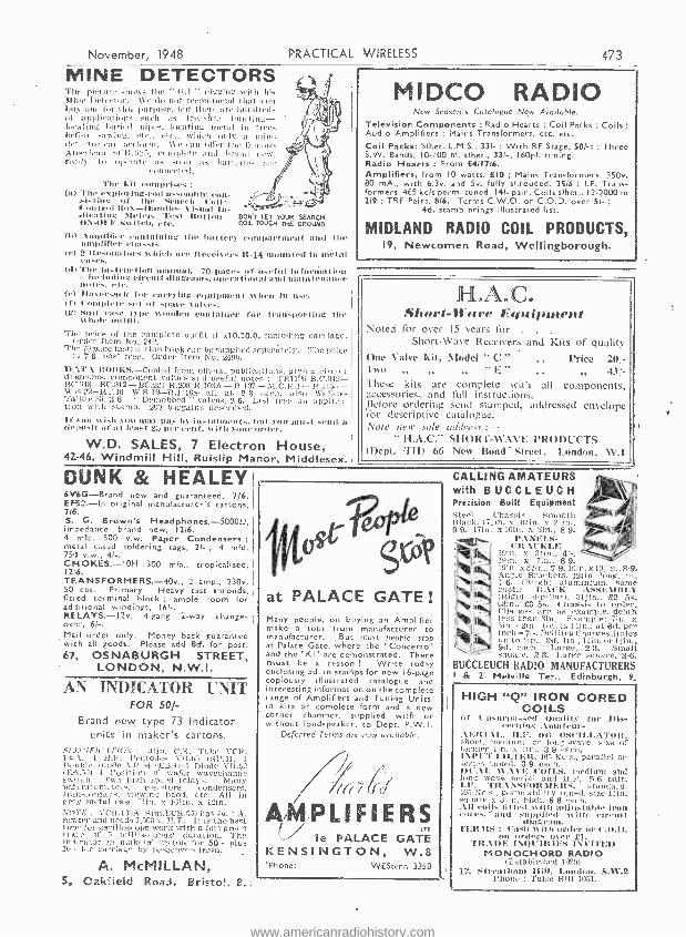
November, 1948 PRACTICAL WIRELESS
MINE DETECTORS The pietur, shows the " 14.1." digginu with his Aine Detector. We du not recommend that cou hey une for fills laurpo.c. lint there :ire hundreds of iun: such :is tr4,141re hnutina - ]oreJiug bgri.d pipe, lucaliul 11111411 in tris.. ber re snwinu, ch'.. 'tr., svhtii only a mine 0,4 can perform. fie tunii offer the notions A..tic:Jn %l'it.Ie_3, complete and brand new, rally to operate as soon as bat lyrics arc
connected. The kit COnq mises
(a) The exploring -rod a..enlltb'. eon- -slsl inv.' of the Se:urh iron t roi Rox- Noodle- t "islutl ln- 1. -..T idlest ling Miler. 'l'est 14ti t ton- DON'T LET YOUR SEARCH O \ -OF'F !taw Lich. eye. COIL TOUCH THE GROUND
(h) .t n11ttitie1 containing lite batter compartment and the amplifier (tutu s, (e) 2 It ewua tors olden are Iteeelcers R -14 led in metal eases. (d) "rho ins t ract ion manual. 70 pages of useful in formation -includinc circuit diagrams, operational and Main is moats
(e) Ilatev.nc l: l'or earrylug eryulpment ys hen in use. If! t'0rnple to I of spare salves, (g) Silly. case type wooden Container roe transporting the
ys hole outlil. The price of the complete outfit if £10.10.0, including carriage. Order Item No. 249, The 70 page instruction book can be supplied seliarately. The price
in 76. post free. Order Item No. 249h. D.t'r.t ROOKS.- Copied from official publications, giving ireuil diagrams, component values and useful notes : TR11NI- B.C,342- 13C,348- BC.312 -BC. 221 -R. 208- R.103A- R.107- M.C.R.1- R.1135 -,
w Sî.22- RT.18 -W S.19- R.1116a -all at 2 3 each, also Walkie- Talkie 58. 3 6. " Demobbed " valves, 2 6, List Free on applica- tion with stamp. 200 bargains described. If inn wish 31111 may pay by Instalment.. but yuU must send a O, u,i,sil or at least 25 per 11111. uilk your order,
W.D. SALES, 7 Electron House, 42 -46, Windmill Hill, Ruislip Manor, Middlesex.
DUNK & HEALED
MIDC0 RADIO .v Season's Cctalogue New A,,n -uhle.
Television Components : Radio Hearts ; Coil Packs ; Coils Audio Amplifiers ; Mains Transformers, etc. etc.
Coil Packs: Slhet. L.M.S., 331- ; With RF Stage, SOI -: ; Three S.W. Bands, 10 -100 m. slhet., 331 -, 160pf. tuning. Radio Hearts : From £411716.
Amplifiers, from 10 watts, £10 ; Mains Transformers, 350v. 80 mA., with 6.3v. and Sv. fully shrouded, 2516 ; I.F. Trans- formers, 465 kcls perm. tuned, 141- pair; Coils slhet., 12-2000 m 219 ; TRF Pairs, 816. Terms C.W.O. or C.O.D. over SI- ;
4d. stamp brings illustrated list,
MIDLAND RADIO COIL PRODUCTS, 19, Newcomen Road, Wellingborough,
JIILoAnCa Short -D'are Equipment
Noted for over 15 years for . . .
Short -Wave Receivers and Kits of quallil One Valve Kit, Model " C" Price 20 -
Tao ,, E
43 -
These kits are complete with all components, accessories, and full instructions. Before ordering send stamped, addressed envelope l'or descriptive catalogue. Note new sole odldress :-
" H.A.C." SHORT -WAVE PRODUCTS (Dept. yí13) 66 New Bond- Street, London, W.1
6V6G -Brand new and guaranteed, 7)6. EF50. -In original manufacturer's cartons, 716. S. G. Brown's Headphones.- 500012, impedance, brand new, 1216. 4 n)ld. 500 V.W. Paper Condensers metal cased soldering tags, 21- ; 4 mid. 750 v.w., 41 -. CHOKES. -ION 300 mia., tropicalised, 12,6. TF.ANSFORMERS. -40v., 2 amp., 230v. SO cos. Primary. Heavy cast shrouds, fined terminal block ample room for additional windings, 16!-. RELAYS. -I2v, 4 -gang 2 -way change- over, 61 -.
Mail order only. Money back guarantee with all goods. Please add ed. for post.
'67, OSNABURGH STREET, LONDON, N.W.1.
AN INDICATOR UNIT FOR 501 -
Brand new type 73 Indicator units in maker's cartons.
RFI:CYF1i'.1TlU \' : olio. C.R. Tube. VCR. 131)A. I H.F. Pentodos VR (SP.41) 1
Double Diode b F 4 (E13.4) 1 Dodo VR.02 10,5 -'b 4 Position m 111 wafer w avcchange
I) Two high saved t el ys Many peler I. omcte resistors condehserv, tr 1 -.11.erret. viewing hook etc. All in ersy metal case 1.1111 y 161in x 12ín. NOTE ; vCR 13111, (Sim ECR 4) has 4v. l A. his ter and needs 1,500 V. H.T. It is the best toue for oscilloscope work with a fire green I rat.( of 5 milliseconds' duration. The in licator i;) inalteial carton for 50:- plus
for (amide,( by passenger - ttai-li,
A. McMILLAN, 5, Oakéieid Road. Bristol, A.
P.O
CALLING AMATEURS with BUCCLEUCH Precision Built Equipment Steel Chassis Smooth Blank, 171in. x 101-in. 9 9. 17in. x loin. x 2in., 8 9.
PANELS- CRACKLE
19in. it 3 :ín., 4' -. lutin. x 7111.. 6 9. 19ín. x 7'9.19in. x.. 101 in.. 8-9. Angle Brackets, 121in. long, pr. 7-6. (Bright aluminium, same cost.) It All: ASSEMBLY (Rigid 4- pillar), 311in., £2 5s. 63in., 63 5s, Chassis to order. Cliatges are as example, depth less than 3in. Example: 7ìn. x
2in. totals 14!n.. at 811. per inch =7 -. DrillingCharges :Holes up to !in., On. lin., 11in. orpin., 9.1. each. Large, 2'3. Small square, 2 3. Large square. 3-6.
BUCCLEUCH RADIO MANUFACTURERS I & 2 Melville Ter., Edinburgh, 9-
t PALACE GATE !
Many people, on buying an Amplifier make a tour from manufacturer to manufacturer. But most people stop at Palace Gate, where the ' Concerto' and the ' Kt ' are demonstrated. There must be a reason ! Write today enclosing 5d. in stamps for new 16 -page copiously illustrated catalogue and interesting information on the complete range of Amplifiers and Tuning Units, in kits or complete form and a new corner chamber, supplied with or without loudspeaker, to Depc. P.W.I.
Deferred Terms are now available.
p(( (0r
AMPLIFIERS Cz' ie PALACE GATE
KENSINGTON, W, £l
'Phone: WEStern 3350
HIGH "Q" IRON CORED COILS
of l'nsuepassed Ituality for Dis- evening .tara leurs
AERIAL. II. F, OR OSCILLATOR. short, medium or lung ,wave, size of dormer lin. x :it)., 3'9 each. INPUT i 11 71 R. 485 Kos.. parallel or erns tuned 9 each
1111 1.11.. WAVE 1; (O11 medium and long wave aerial and H.P. 946 pair. I. F yell t\SEt11t MERS, standard, 455 Rc s., permeability tuned, size 11ut. square s 3 u) high, 86 each. 11l coils fitted 'Mill adfuslablr iron tort. ' and supplied with circuit
diagra nl. TERMS : ('ash with order or C.O.D.
MI orders over £1. TRADE INIit' IR IES INt'I'r11) MONOCHORD RADIO
(Established 152(11
17, Streatham /IHI. London. S,.%V.2 'Phone : 'foire Hill 1051.
www.americanradiohistory.com
474 'PRACTICAL WIRELESS
000 TELEVISION COMPONENTS
Constructional Booklet (Elec. £ 2 Complete Chassis Assemblies
with gantry. etc. ... ... ... 4 4 Separate Chassis
1. Vision unit chassis fitted with screens, all valve holders and fully drilled
2. Sound unit chassis complete as above (incl. coil formers) ...
3. Time Base chassis with valve holders, etc.
4. Power Pack chassis with holders and fully drilled
Separate Mains Transformers E.H.T. 5,000v. 1 mqa L.H.T. 4v. and 6v. 350v. to E.E.
specification ... ... ... Deflector ('oils
Grade 1 for 35 mm. tubes ... Superior quality. type 7840 ..
Focus ('oils 3.000 turns 29 swg. 115 ohms ...
Line Transformers Min. Ind. 1 hy., 100 ohms for EL38 op Pen 46 ... ... 2 6 0
Frame 'Transformer. Ind. 125 hy., 120 ohms. Ratio 9.6 2 5 0
Line Blocking Transformers 9 0 Also 9in, and 12in. Cathode Ray Tubes at current prices. (Callers only, due to trans- port difficulties.) Smaller components stocked where possible. Complete kits
available.
The TELERADIO Co- 157, Head
oorre Office
N.IB Also 669, High Road. N. 17. and 224. Ching-
ford Mount Road, E.4
1 2 6
17 6
1 2 6
1 0
3 7
3 19
0 2 12 0
1 12 6
01
6
6,
0
- NEW G.P.12 CRYSTAL PICK -UP with permanent sapphire stylus
-was fully described in The Wireless World's recent article " Crystal Pick -Ups -Basis of Design for Fidelity Reproduction."
This remarkable pick -up, which represents the ultimate in high -fidelity reproduction, is now available in limited- quantities through your radio dealer, price 1041 - incl. P.T.
FREE ILLUSTRATED FOLDER describing this new pick -up may be ob- tained by returning the
coupon below.
r TO COSMOCORD LTD.. 1 ENFIELD, MIDDX, I
I Please send folder of ACOS Pick-ups. i
I NAME
I ADDRESS
1 P.W. --- I
The " Fluxite Quins " at Work "An aerial needing repair!
Set up without FLUXITE, I'll swear. Pull hard, it's got fixed," Cried 00. " You're all mixed.
That's the telephone wire you've got there."
See that FLU XITE is always by you -in the house -garage - workshop - wherever speedy soldering is needed. Used for over 40 years in government works and by the leading engineers and manufacturers. Of all ironmongers -in tins,
10d., 116 and 31 -.
To CYCLISTS : For stronger wheels that will remain round and true, there's a time tested tip. Tie the spokes where they cross with fine wire and SOLDER. It's simple - with FLUXITE -
but IMPORTANT.
The FLUXITE GUN puts FLUXITE 'where you want it by a simple pressure. Price 116, or filled, 216.
ALL MECHANICS Will
IT SIMPLIFIES ALL SOLDERING
Write for Book on the ART OF " SOFT " SOLDERING and for leaflets on CASE-
HARDENING STEEL and TEMPERING TOOLS with FLUXITE, also on " WIPED
JOINTS." Price Id, EACH.
FLUXITE LTD. (DEPT. W.P.), BERMONDSEY ST., S.E.I.
November, 1948
SPARKS' DATA SHEETS
Provide detailed Instructions with -
Clear, Full -size Constructional Prints of - Tested and Guaranteed Designs.
THE "CONQUEST " My Latest Design. A Very Efficient A.(''.'I),('. ALL- WAVE I( SUPERHET
Five Valves, including Rect. Delayed A.V.C. 4 Watts Output. Y.U. Con- nections. Good Range, Selectivity and Quality ... ... ... ... 2(9
THE " CRUISER " All -dry T.R.F. 3- Valver for use with short aerial 2l8 THE, " CUB." A.C.)D.C. 2- Valvër Plus Rect. Med. and Long waves ... 2'8 THE " CADVF." A.C.!D.C. 4 Watt Amplifier. Ideal for P.U.... ... 216
THE " OLD FOLK'S TWO." An A.C.!D.C. 2- Valver, plus Rect., having Station Selection by Switch ... 2.9 THE " CHALLENGER." An Out- standing' A.C. D.C. Portable for use in any rodm without aerial or earth 3 -Valve T.R.F. circuit, plus Rect. 2 9
A.('. TWO- VALVER (Plus Reef.). M L Waves. Fine Power and Tone 2.6 A.C. THREE-VALVER (Plus Rect.). T.R.F. Circuit. M Watres
MANY OTHER DESIGNS for Sets, Portables and Amplifiers. Stamp for List and with order. Prompt Service. Components supplied.
L. ORMOND SPARKS (P), 9,' Phoebelh Road, Brockley, S.E.4 (Nearest Station : Lady well S.R.)
('Phone : Lee Green 0220.)
CHARLES BRITAIN (RADIO), LTD. II, Upper Saint Martins
Lane, London, W.C.2.
BEST BUY AT BRITAINS
MAKING A SCOPE ? Test Set 74 is the ideal unit for this purpose. It works straight off the mains and we can supply detailed instructions for making a scope which any schoolboy can follow. Details as follows. Size of case 18in. x 12in. x 9in., I 6Q7 ; I, 615 ; I, EAR' ; I, 5Z4 ; I, CV6; 5, SP6I ; I, HVR2A ; Sin. Tube VCRI39A. Complete with the necessary mains supply and smoothing, etc. All in- struments tested before despatch. Price with full instructions, £611010, or less instructions, E511010, plus 151- carriage. TYPE 26 R.F. UNITS, tuned 5 metre Converters. Brand new in makers cartons. Price 2716, post. free. RI 124 RECEIVER. -Range 30-40 mcls ; contains six new valves, 3, 9D2; I, BD2; I, ISD2 (Frequency Changer); I, 4D1; 24 ceramic trimmers, 6 Ceramic valve- holders, 6 valve screening cans, 30 resistors, 3 potmeters, mica and tubular condensers, ceramic coil formers, 5-way 4 -bank switch with .long spindle and I.F. transformers, etc., a real buy at only 1916, plus 216 carriage and packing. BRITISH I.F.F.- Complete in case, size 12ín. x 8in. x 12ín. Contains 10 valves, 1
motor generator, numerous relays, pot - meters, resistors, etc. The generator, which is complete with all gears, etc., can easily be converted to a small motor for A.C. or D.C. operation. This really is a genuine bargain, at only 1916, plus 51- carriage and packing. Hundreds of other lines in stock. Many. special bargains for callers. Shop hours, 9 a.m. to 6 p.m. For the convenience of customers we are now remaining open ail day Saturday. Phone : TEMple Bar 0545.
www.americanradiohistory.com
November, 194$ PRACTICAL WIRELESS 475
ProcrQrnme Pointers This Month, Our Contributor, MAURICE REEVE, Deals with
the Sub;ect of Running Commentaries
THE chief broadcasts during the summer months are, I suppose, the sporting com- mentaries and the Promenade Concerts.
The former take precedence during the day and the latter in the evening. But whilst the latter are of a uniformly high standard with a general upward trend- witness this season's acoustical experiments in the Albert Hall, to the advantage of those inside as well as outside the Hall -the former are certainly no hetter,than the generally poor level on which they have always rested, but are, if anything, below it.
For years now the art of commentary has been stabilised in a groove. A small handful of adjectives are repeated ad nauseant -the " impressive " scene afforded by Wembley Stadium at all sporting contests, a " long, raking kick " at Rugby football, " a Eour all the way " at cricket, etc, etc. Similes and descriptions are just the same. If a cricketer wears his cap at a jaunty angle, for example, we are not only told so at every match in which he appears, but every time he comes out to bat, is put on to bowl, or does a smart bit of fielding. Again, if he is the youngest player ever to have accomplished whatever it is he has just accom- plished, or the oldest, or the fattest, or the thinnest, we are told so, and told so, and told so, again and again.
Of few broadcasting activities can it be truthfully said that no improvement has been made over the last 10 to 15 yeárs. But I do feel that this is no exaggeration so far as sports commentaries are concerned, and Test matches in particular. As these are given far more time on the air than any 'other sporting event and should, I feel sure, be at least as exciting as any other, if even only for their rarity, I would like to go into the question in some detail. They wore, as a matter of fact, the most boring and exasperating broadcasts imaginable, and the commentators themselves must be held chiefly responsible.
It can be taken as an axiom that the shorter the event and, in consequencb, the shorter the commentary needed, the better it will be. The Derby or the Grand National are perfect examples. But when the race itself takes about five minutes at the most, plus ten minutes for description of the scenes and the field, it is difficult tb imagine anyone not being able to give a reasonably good account of himself, excellent as Raymond Glendenning always is. But where the event is drawn out over several clays and is frequently static over long periods, as in a Test match, the gifts of the first -class commentator should shine at their brightest. It is, alas, where they completely fail. They are totally unable to convey the drama and tenseness of the scene, except for the shortest periods, as opposed to the rush, bustle and excite- ment of Wimbledon or Aintree. And they are not always as knowledgeable of the game as they should be- witness their frequent inability to detect a catch off a bump ball and their joining in the
jubilation of the crowd whenever such a catch is made. Rex Alston's description of an imagined catch in the slips during the fourth Test : " He's caught in the slips -no, he isn't -he would have been had second slip been a yard to his right," deserves to go down as a classic example of wishful thinking. As does his crowd description during a shower of rain or something : " The ground presents a marvellous sight, absolutely marvellous. The men in their shirts, the women in their blouses... ." No wonder the poor men can only make recourse to the constant and never- ending repetition of the score card. Repetitions
The card of the match is read to us at least six times in the first half hour of play, it is repeated at the close and commencement of every session of play, at the fall -of every wicket, at the close of play, at every interruption through rain, the number of repetitions depending on the length of the interruption -every time a new programme comes on the air or goes off, as well as on numerous -
other occasions as circumstances permit. Terrible, shocking and wearisome in the extreme. And totally unnecessary if the commentators were able to " put the thing over " as Howard Marshall used to. John Arlott, probably the best and certainly the wittiest of the team. as E. W. Swanton is the most knowledgeable, is the worst offender in this respect.
A word in conclusion on the " expert com- mentaries from time to time." Hero is a typical example, and they never vary. The event, say, a catch, described thus : " So-and -so has driven a ball from So- and -so high past mid -on. So- and -so's racing for it. Yes, lie's out. So- and -so's out, magnificently caught ; he had to run quite thirty yards but he judged the flight of the ball beautifully and held it as it came down at an awkward angle. Now we'll see what Arthur Gilligan has to say about it. Come in, Arthur, and tell us what you thought of that catch." Enter Arthur. Arthur :
" Well, Rex, I think your description was absolutely correct and I agree with you entirely. So- and -so drove that ball of So- and -so's high past mid -on and So- and -so, judging its flight beautifully, raced round, I should say, thirty yards, and held it as it was coming down at a very awkward angle." Then follows the ttth repetition of the score card and the new batsman prepares to receive his first ball. Serialisation
The Australians will not be here again for four years. Is it too much to hope that their broadcast will be on entirely different lines ? I am con- vinced they can and should be among the most exciting and dramatic of all outside broadcasts, if put in the right hands. If, however, the boredom and monotony of this season's series cannot he overcome, better scrap them altogether and let the score card be read out, say, once every hour.
The successful adaptation for broadcasting of
www.americanradiohistory.com
476 PRACTICAL WIRELESS November, 1948
the full -length novel has also not yet reached perfection, though much success has been achieved. The current serialisation of Bennett's " The Old Wives' Täle " suffers from too much retrospective commentary by the narrator who, instead of pointing a guiding finger, as it were, clown the road the story is going to take, takes too much of the story- telling on his own shoulders. Neither the cast nor the story are sufficiently left to their own job ; it is as though they were not trusted to " come over " without his constant interference. They would, and with benefit to the dramatic sweep of the story which would be heightened, if he made his presence a little scarcer.
I felt that Ruth Draper's performance, July 8th, lost by the absence of her compelling and bewitching personality. One must be able to see this distin- guished artist as well as to hear her, if we are to get completo satisfaction from her incomparable performances.
The Shop at Sly Corner," July :t 1st, was very .good. This inconsequent little thriller, whose
News from PETERBOROUGH AND DISTRICT RADIO AND SCIENTIFIC
SOCIETY Hon. Sec.: Woodward, 72, Priory Road, Pet e rhurough,
Nola h: TII I: ,r e has its own transmitter .wlnieh lias been built
IuI members mut is housed in the Club House. ('all is G:; I rQAW.
Meetings are held in the Chili House every Tuesday and Thursday evenings, at 7.30 p.m., and also ou Sunday mornings, at 30.4 :i a.m. 'Tuesday evenings are devoted to ut glass for mem- bers wishing to take the examinations for a Transmission Lie. nee,
and the transmitter is ..,,also oil the air. (ieueral lectures are given au Thursday evenings, including a monthly lecture on television and one on radio valves.
The society held a Radio Exhibition in the Town Hall, Peter- borough, in September, where local radio trailers and the G.P.O. had stands. 'l'he exhibition was organised to let the public know the work ol'the society and to raise funds.
READING AND DISTRICT AMATEUR RADIO SOCIETY
Hon. See. : Alex Mercer (Scribe), 23, Oakley Road, ('aversham.
M.R. J. DEE (tI313.1 E) recent ly gave a talk on methods of
overcoming television interference. Designs for, and the location of, harmonic filters and stubs within the transmitter were discussed, particular attention being paid to the screening of these elements, to overcome the effects of radiation from the tiller itself.
Seven groups, comprising 32 persons in all, took part in a
five metre direction finding contest in the Mortimer region. Equipment was such as could be carried by walkers or cyclists, and points were allocated for accuracy of bearings, rather than Si eed in locating the transmitter. Two groups did succeed in locating the Tx in the two and a half hours of the contest.
The maps from the D.F. contest were examined at a later meeting, and points of interest discussed. Mr. Guy (CI ST H') was declared the winner of the cord est. Mr. Dee then continued his sit of T.V.I. front the presi n- meeting, and finally ideas for a
Innnher Ilcld -day were disco- -I,
LIVERPOOL AND DISTRICT SHORT WAVE CLUB
Hon. Sec.: W. G. Andrews, 17, Linglield Road, Broadgreen, I.iiurool, 14.
TILE main item on the July agenda was a business meeting
from which emerged the programme for the fortheoniig season. One period per month is now devoted to the solution of members' knotty problems, when all hands come forward with advice and (it is hoped) the solution.
A short talk was also given by ft 31YVW on an electronic " bug " built during his seagoing career. it 'was agreed that an un- balanced multivibrator would work much better than the switched L.F. squegging oscillator described.
Meetings are held every Tuesday, at 8.0 p.m., at St. Barnabas Church Hall, Penny Lane.
success on the ]Vest End stage seemed to be so much beyond its intrinsic merits, made a most effective radio play, with the narrator telling us just sufficient to remind us who saw it of what it looked like, and no more. Those who didn't had their imagination sufficiently aroused to picture the scene for themselves. The result was, and usually is, in " Saturday Night Theatre," that the story unfolds itself naturally with the climax left to itself to reach whatever 'heights it is capable of reaching of its own accord, with much more effective results.
I still think that, day in and day out, the " Children's Hour " offers a more uniformly high standard of wireless entertainment than any other item in the programme. The way its organisers range over the wide world for material, which always pleases somebody all the time, is an example for everyone engaged in programme building to emulate. Although it admittedly offers its wares to a less critical and sophisticated audience, it is pleacing that audience more constantly than any other programme.
the Clubs TEES -SIDE AMATEUR RADIO SOCIETY Hon. Sec.: H. Walker (í13('13AW), 9, Chester Street,
Vlidrll'sbruugli.
THIS .ociety time have their own Club Headquarters, situated at. 4011, l.intlmrpe ]toad (top floor), and opposite 4t.
Barnabas Church, Middlesbrough, which will comprise cluhromit transmitting room and workshop when completed. All who are interested in amateur radio, whether licenced hams or short- wave listeners, are invited to the clubroom, or, better still, get in touch with the secretary at the above address. Lectures have been given on aerials and radar. 'l'here is to be a radio course and morse class.
STOURBRIDGE AND DISTRICT AMATEUR RADIO SOCIETY, Hon. Sec. : W. A. Higgins, 35, John Street, Brierley, Hill,
Staff's.
ADIEEtiNG of the above society was held in the Science Block of King Edward VI School, Stourbridge, on Tuesday,
August 10th, at 7.4.5 p.m. Considering absences owing to holidays the attendance was good and members listened attentively to thc- seeond part of Mr. loge's talk on " ]'he t'se of the Cathode Ray Oscilloscope." Mr. 11igg gave practical illustrations on hie oscilloscope of valve characteristics, modulation percentages, amplifier distortion and fregne a -e synchronisation. A very hearty acclamation was accorded to Mr. Rigg tin. a truly out- standing talk and demonstration. Mr. Rigg replied saving the pleasure had Leen as much his in having such an enthusiastic; audience.
The next swirl a meeting will be on "]building a Snperhet Receiver," aid will be given by Mr. Bills (03Ch6), of h.iuver, a society member.
THE RADIO SOCIETY OF HARROW Hon. See. .1. It. d'ikctt, 93, \\'hit more Road, Harrow, Middlesex.
MISSEBI:I {SHI P oft he above Soviet y continues to increase, and
a full season's programme has been arranged. This includes a talk and demonstration on October 10th hj Messrs. ])oleo, and a euuctn ctioual competit ion for the Challenge ('up, entries to be judged on December 7th..
Recent talks included "Quality Reception of B.B.C.," "F.l1. Transmission " and "Five -metre Antenna's."
The Society transmitter will Ife on the air shortly and various tests wilI be carried out.
New members are cordially invited to cot act the Hon. Sec. for full details. Meetings are held every Tuesday evening at Northwick 'l'earoonts, Denton Road, Kenton, from 7.30 to 10 p.m.
WORTHING AND DISTRICT CLUB Hon. See. : Mr. L'. '1'. Tooley, 02, Becket Road, Worthing. 9,1115 \Worthing and District Group of the R.S.G.B. Inns been
reformed into the Worthing and District Armateur Radio Club, in order to admit non-R.8.0.13. members to its ranks, thus widening the scope of the club.
Meetings are held on the first. Thursday in each north at Oliver's Cafí, Sonthfan c Road, at 7.00 p.m.
www.americanradiohistory.com

November, 1948 PRACTICAL WIRELESS 477
Meters As specified in PRACTICAL WIRE- LESS, April and June, the best bargain on the radio market. Stocks running low, but we still have :
FLUSH, z,',in. square 0/5 milliamps
-01.5 amp. R.F. with thermo -couple 5/9
Four of these meters (2 of o/5 m/A and 2 of o /.5 amps. R.F.)
Four for 21 /- ' per post 22/-
Also o /15o milliamps 6/6
ALL NEW AND IN MANUFACTURERS' BOXES
5/9
Microphone Testers Air Ministry stock in mahogany case 6in. x sin. x Sin. with hinged lid. Contains o /io volt meter (fundamental o/1 m /A), high - grade mie. trans. and many useful components. Sold elsewhere at 45/-, Our price 32 6.
Condenser Bargains Stock clearance lines, all l00%
perfect. T.C.C. tub. 350v..03 -3d.
450V. 1 mfd. -6d. Mica 350V. .005 -6d. Metal 35ov. .5 -2d.
1,000v. 4 mfd. -5/- Elect. 15ov. 8 mfd. -6d.
Dublier Mica 350v..01 -a /3 Sprague tub. i,000v. U.I.C. Silver Mica 1ió ,os -2/6
POST CUSTOMERS. Please add I/- extra on orders.
WEBB'S RADIO, 14, SOHO ST., OXFORD ST.,' LONDON, W.I. Note our SHOP HOURS : 9 a.m. to 5.30 p.m.
Sato. 9 a.m. to I p.m.
Telephone : GERrard 2089.
ETA FOUR STATION
SUPERHET TUNER A complete pre -set tuning unit, for use in superhet circuits, which can be set to select any three M.W. and one L.W. station. Exceptional sensitivity and stability are achieved by the use of a new type of inductor. Supplied with full instructions and a complete receiver design.
Price 33/- Purchase Tax 7/2
I. F. TRANSFORMER A midget I.F. transformer for 465 kcls, which sets a new standard of efficiency. Size : I }in. diam., thin. high. Trimming of both sections effected above chassis.
Price 7/- each
ETA Components are obtainable from your local dealer or direct from
ELECTRO TECHNICAL ASSEMBLIES
West Hill, St. Leonards -on -Sea, Sussex
MAINS TRANSFORMERS 19/8 POST PAID
NEW GOODS -NOT SURPLUS Primary for 200/230/250v. Drop through type with top shroud. H.T. 250 -0 -250 or 300 -0 -300 or 350- 0 -350v. 80 mA. Universal
VALVES A few of the types in stock -all at reduced P. Tax Rates. Valves sent C.O.D.' Brimar 703. 705, 8A1, 9A1, 902, 10D1, 11D3,
11D5. Cossor : 2P. I3SPA, 40SUA, 41MHL, 41MP, 41MTL, 41MXP, 43íU, 210PG, 21OSPT,
210VPA, 240QP. Marconi -Osram : 304, 1563. DH63, DL74,
H30. N30, H63, HD14, HD24, HL2, HL2 %K, KT2, KT33C. KT41.
Mazda : AC'PEN, AC2 /PEN DD, AC5;PEN DD. AC.HL, DD207, PEN 44, PEN 45, PEN 383. PEN DD 4020. UU5, UU6, UU7, U403. VP23, VP41, VP133, VP210.
Mullard : 2D4A, AC044, AZI, AZ31, CI, SIC, CELI, CBL31, CL4, CL33, CYI, CY31, PM2A, PM22A. FC2, FC2A, PEN36C, TH30C, UBL21, UCH21.
Tungsram APP4A. APP9B. APV4, AS4120, AS4125, HL2. LP220, MH4105, P215, PP215, PP35. V30, PV495.
American Types IA5, IA7, IC5, IRS, INS. IR5, 155, IT4, 3Q5, 5U4, 5V4, 5Y3, 573. 5Z4, 6A7, 6A8, 6C6, 6D6. 6K8, 61(7, OJ8. 6L6, 6L7. 6U7. 6P6. 6V6, 42. 80.
MINE DETECTOR AMPLIFIERS 3 valve- R.C. Midget Amplifiers with three IT4 valves in ceramic holders, 22:6.
.3 AMP LINE CORD 50 70 ohms per ft. 2 was'. 13 Yd. ; 3 -way,
1,6 yd. I'M/MILLED AL( ";MINIUM ('RASSIS
Heavy gauge, 16 B.W.G. Polished. 3in. deep, 4 sides. 10in. x 6in., loin. x Rin., 8'6 ;
12in. x 9in., 10 /8 : 14in. x 9in., 16in. x Sin., 11,8 ; 20in. x 8in., 12/6.
NEW GOODS ONLY. C.W.O. or C.O.D. POST FREE OVER 5, -.
COULPHONE RADIO The Return of Post Mail Order Service, 58, Derby Street, Ormskirk, Lancs.
Send Sid. stamp for 32 vase catalogue
GALPIFV'S ELECTRICAL STORES
408, HIGH STREET, LEWISHAM, LONDON, S.E.13.
Telephone : Lee Green 0309. Near Lewisham Hospital.
TERMS : CASH WITH ORDER. NO C.O.D.
ROTARY CONVERTERS EX- ADMIRALTY 110 volts D.C. to 230 volts A.C. 50 cyc. 1 phase rated at 200 watts but capable of 550 watts continuous rating, weight approx. 100 lbs., £81101 - each, carriage 101 -. Another Ex- R.A.F. 12 volts D.C. input, 220 volts A.C. 50 cys. I ph. at 100 watts output approx. weight 151bs., as new, 851- each, carriage 316. VARIAC TRANSFORMERS. Input variable between 2001240 volts output constant at 220 volts at 7k amps., 901 - each, carriage 51 -. ELECTRIC LIGHT CHECK METERS (Watt Hour). A.C., 50 cys., 2001250 volts, 5 amp. load, 1816, post 21- ; 10 amp., 211 -, post 21- ; 20 amps., 251 -, post 21- : also a few only Pre -Payment I I- slot type, 20 amp., load, less coin box, complete with syn- chronous Motor, 351- each, carriage 316. EX- R.A.F. INDICATOR UNITS, type 48a, new, boxed, consisting of 2, 3Iin. tubes, type 138a, also time base, 501- each. MOTOR ALTERNATORS, EX- R.A.F., as new, 230 volts 50 cys. I phase input, 250 volts 625 cys. 1 phase at .24 amps. output, 751- each. Ditto, 1,725 cys. output, 851- each. CIP. EX -NAVAL )in. SPARK COILS, approx. 3,000 volts from 6 volts supply, 816. G.P.O. Galvanometers, reading 3010130, vertical type, 816 each. Ex- R.A.F. Impulse Transformer (Magnetron), output believed to be approx. 1,500 volts at 3 kW., for 1 m/s., 716 each. Variometers for No. 19 Mk. 11 Receivers, 614 éach. EX -NAVAL (CROMPTON PARKIN -
I SON) PRONG -TESTERS, 0 to 100, and 0 to 400 amps., new, in leather carrying case, 901- each. A.C. V1Meters, 0 to 300 6in. scale, calibrated 50 cys., 3716 each. EX- R.A.F. CRYSTAL MONITORS, type 2, complete in wooden carrying case, the frequency depending on crystal used 51- each. Short Wave Aerial Coupling Units (Wavemeters), 51- each. FRACTIONAL H.P. MOTORS, 110 volts with LAMINATED Fields (Ex -Naval Fan Motors). These need slight attention, to brushes or leads, 101- each. Westing- house (Blasting) Galvanometers, Moving Coil, very low deflection, 151- each. LARGE TYPE RECTIFIERS. Output 50 volts at I amp. :4 wave, input voltage 70175 volts, 1716. Tannoy P.M. Speakers (Small Hailers), 7 ohm. speech coil, com- plete with output Transformer, 151 -. MAINS TRANSFORMERS, by well - known makers, input 2001250 volts, output 1,0001011,000 volts at 500 mla., 751 -. Another 1,1501011,150 v. 500 mla., 851 -. Another, with two 7.5 v. two 6.3 v. and one 4 v. winding all at 10 amps., 3716. CONDENSERS. 4 M.F. at 2,500 v. wkg., ISI -. M.F., ditto, 251 -, SPECIAL OFFER METERS, all new boxed. Moving Coil, first grade instru- monts, 0 to 20 volts, 101- each, or 3 for 251- ; 0 to 40 volts, 1216 each ; 0 to 10 amps., 151- each, all tin. scale. 0 to 20 volts, A.C., calibrated, 50 cycles, 251- each, 0 to 4 amps., thermo- coupled, 251- each. MAINS TRANSFORMERS, as. new, input 230 volts, 50 cycles, output 12 volts at 8!. amps., A.R.P. shelter transformers, 251- each, post 21 -. EX- R.A.F. RF UNITS (new) packed, containing 6 valves, all 6.3 heaters, including grounded grid triode, also a miniature 24 -volt motor (universal) and approx. 80 resistances and condensers, all mounted on silver- plated chassis, to clear, 3716 each, carriage paid,
www.americanradiohistory.com

478 PRACTICAL WIRELESS November, 1948
COVENTRY RADIO COMPONENT SPECIALISTS SINCE 1925
HAVE YOU RECEIVED OUR 1948/9 NEW RADIO COMPONENT CATALOGUE ?
THE FIRST ISSUE WAS SOLD OUT IN 14 DAYS. THE FINEST GUIDE OF PRICES TODAY, DETAILS OF HUN- DREDS OF DIFFERENT NEW COMPONENTS. NEW ISSUE NOW READY, SEND 3d. IN STAMPS.
EQUIVALENT LIST OF SERVICE VALVES, NOW READY, PRICE 6d. (CV., VR., VT., ARP Nob. TO COMMERCIAL TYPES).
COVENTRY RADIO DUNSTABLE ROAD, LUTON. Phone : Luton 2677
TORBAY ELECTRIC SERVICE We guarantee to despatch all orders on the same day that they are received. This means that In most cases you are actually fitting the component into your rig only 48 hours after writing out the order.
AE.F,e ORDERS CARRIAGE FREE Our 12 page catalogue gives full details of the items stocked: why not write for a copy? It's entirely free, send a postcard. Some of the items taken at random. BC453. the QSer, we have a special illustrated leaflet dealing with this, send for a copy. Type 10 remote control units, £12. 1154 Transmitters. £8. B.C.603. 10 valve receivers, £7 10e. Od. S130 voltage stabilizers 5!- each. High Res, headphones, 8(S. .25 mfd. 2kVW at 13. National HRO sloW motion dials, Iron cores for coils, not very often that you see these, 4d. each. Agents for everyone, Belling -Lee, Bramar and S.T.C.. Denco. Gardeners, Muirhead, Partridge, Taylor, Wearite. Woden, etc. Send for that catalogue now, there's bound to be something that con want.
TORBAY ELECTRIC, Paign ton, S. Devun. 43. (volley End Park.
LASKY'S RADIO NON I. \IBER SPECIALS
EN A.M. t \I1'. Type 567c'ww. Brand new and unused in maker's original cartons. Containing 11 new valves :
2 5Z4g, 2 5Ú4g, 1 SU2150A, 1 6X5GT. 1 EF50. 1 CV137, 2 VS70, 1 6V6g. Dozens of various components, including high voltage con- densers, pot'meters, resistances, condensers (8 mfd. 500 v.w.), chokes, etc. Totally enclosed in metal case. Size 12in. x 111in. x 8in. LASKY'S PRICE 39'8. Carriage 4'6 extra. EX A.M. MODULATOR UNIT Type 64. Containing 7 valves: 2 EF50, 1 807, 2 high voltage rectifiers CV54, 1 CV85 (Special Type), 1 CV73, 3 Relays. High voltage condensers, resistances, pot'meters, and other components. Enclosed in case size loin. x Bin. x 61n. Weight, 351bs. LASKY'S PRICE 226. Carriage 5'- extra. EX A.M. RECF.IV'ER Type 3515. Contains 21 valves: 10 VR65, 1 EA50, 1 EB34, 5 VR56, 1 VR53. Hundreds of components, con- densers, resistances, relays, I.F. strip. coils. etc. (The I.F. strip in this receiver can be removed and used as a separate unit.) The whole receiver is totally enclosed In a metal cabinet size 18in. x 12ín. x 91n. Weight, 251bs. LASKY'S PRICE 396. Carriage 4'6 extra. EX A.M. P.P.I. INDI('ATOR UNITS. Containing 12 valves and two cathode ray tubes. bin. VCR517 and 21in. VCR139A. Dozens of components. 5 EF50, 3 VR65, 4 EA50. Resistances. condensers, trans- formers, coils, etc. Enclosed in case size 12ín. x 9in. x 19in. Weight, 401bs. Set supplied with all valves. LASKY,'S PRICE 59.6. Carriage 7 6 extra. The above units are only a few of the amazing bargains from our extensive stocks. Write to -day for our latest bulletin (enclose 21d. stamp) of other ex- Government bargains. We have the unit you want.
LASKY'S RADIO. 370, Harrow Road, Paddington, London, W.9 (opposite Paddington Hospital).
Telephone: Cymningham 1979. Hours: Mon. -Sat. 9.30 a.m. to 6 p.m.,
Thurs. half day.
A FREE BOOK ou More Code Training
Thera are Candler Morse Code Courses for Beginners and
Operators. Send for this Free '..BOOK OF FACTS" It gives full details con-
cerning all Courses.
THE CANDLER SYSTEM CO. (6.L.O.) 121, Kingswny, London, W.C.2.
Candler System Co.. Denver. Colorado. U.S.A
H.P. RADIO OFFER
SERVICES LTD.
Brand New Ex- R.A.F. R1224a Battery Communication Receiver. 5 Valve Superhet of Exceptional Efficiency, 3 Wavebands 3e -î0m., 70 -150 m., 150.300 m. Valves : 2,VP23s, FC2A, HL2, PM2A, all included. Has R.F. Stage. Muirhead preci- sion Dial. Two Output Jacks, Low H.T. Consumption. Cabinet finished AIR MINIS- TRY grey. Size 151n. long, 10ín. high, 9in. deep. Requires Aerial. 120 v. H.T., 2 v. L.T., 9 v. G.B. and Loud `Speaker or 'phones to put into immediate operation. A Super DX receiver. Easy operation. All leads marked. Ideal for the Radio Amateur. Yachtsman, Lighthouse Keeper, Met. Stations and all remote locations. Price £5 10s.. Carriage Paid per pass. train. Instant Delivery. Satisfaction Guaranteed or'Money returned within 7 days.
H.P. RADIO SERVICES LTD. Britain's Leading Radio Mail Order Howe,
55, COUNTY ROAD, WALTON. LIVERPOOL 4
Tel.: Aintree 1445. Established 1935. Staff Call Signs G3DLV', G3DG7..
BULGIN A Name famous
in Kallio
A. F. BULGIN& CO., LTD.
Bye Pass Road, Barking, Essex
Tel : RiPpieway 3474 (5 line,).
T R? / IF Olt ZLil Y-lOML
CONSTRUCTOR We specialise in supplying complete kits and individual component parts for all circuits described in this jom'nal.
5 VALVE A.C. MAINS SUPERHET KIT, 3 waveband. 16.5 -50, 200 -550, and, 800 -2,000 metres, complete with valves and speaker, £14 17e. ld. : also supplied to cover 12.5 -37. 36 -120. and 200 -550 metres.
D.C. version. £13 7s. 4d.) Wiring diagram and instruction sheet, 2'9 Poet . free. ALUMINIUM CHASSIS (22 gauge), sin.' x 6110, x 21ín.. undrilled 5.'-, drilled to own specification at extra cost. SCREW (:RIP 'TOOL. (For working screws into awkward corners.) l'9 post free. POCKET VOLTMETER, moving coil, ranges 015 and 0;250 volts, D.C., 18,6. KIT OF METAL TAGS. ET('. A strong cardboard case containing 13 boxes of approx. 100 each of different Solder Tags. washers, metal lead ends and self -tapping screws, 25, -. TELEVISION COMPONENTS. Guaranteed '
suitable for " Electronic Engineering " designs. Scanning Coils. 35 `. Focus Coil. 33' -. Line Transformer, 27 6. E.H.T. Transformer, £3 5s. Mains transformer.. £3 15e. Send 21d. stamp for our Brochure of Kits. Also details of our Practical How-to- Build- it Books complete instructions and designs for the HOME CONSTRUCTOR.
HENBEST BROS., LTD.,
26, Green Lanes, London, N.13 Telephone : BOWES PARK 6289.
DO YOU FIND RADIO HARD WORK ?
To do anything really well involves hard work, but that is where we come in. Our technicians have designed really special coils and assembled them into units, together with all switching, trimmers. padders, iron cores, etc. All you do Is wire the remainder of your circuit. These packs are 3 -wave superhet, T.R.F., superhet with RF stage, push- buttoniwith gram. switching, etc. Send for your gift copy of " The Home .
Constructor's Handbook " of tested cir- cuits, hints, formulae, components, etc. See how really easy and cheap radio can he !
Space doesn't allow details, but you'll be amazed at our parts prices -about half the price you normally Pay !
Send NOW for this 26 book which we are offering for a limited period ONLY for three 2íd. stamps for postage, etc. Be introduced to our profit- sharing scheme 1
Earn easy money in your spare time 1 '
RODINGi LABORATORIES, (Electronics). Dept. P.
^0 I ord Avenue, Ilford, ESSEX..
www.americanradiohistory.com
November, 1948 PRACTICAL WIRELESS 479
Impressions ®n Review of the Latest
THE piano is featured prominently in the latest releases, the first being Artur Schnabel's interpretation of Brahms Intermezzo in
E Flat Major, Op. 117, No. 1, and Intermezzo in A Minor, Op. 116, No. 2, on H.M.V. DB6505. The first of these two Intermezzi has a few lines of poetry at the head of the score taken from a German version of Lady Anne Bothwell's lament, " Baloo, my Babe." It is one of Brahms simplest and most popular piano pieces, though by no means easy_ to interpret successfully. Artur Schnabel plays the tune with great feeling, and conveys admirably the darker mood of the middle section. This great artist's handling of the somewhat less familiar A Minor Intermezzo is equally fine.
Chopin's famous Polonaise in A Flat has again been recorded and this time by Louis Kentner, on Columbia DX1502 and, finally, two moire of Chopin's works, Nocturne in B Major, Op. 32, No: 1, and Waltz in A Flat Major, Op. 34, No. 1, are played by Pouishnoff, on H.M.V. C3773.
At one time during political conflict between Finland and Russia the performance of Finlandia was forbidden. This tone -poem is só intensely national in sentiment that it has become almost a patriotic anthem for the Finns. Its melodies create the impression of its being a fantasia on genuine national airs ; but the composer has stated emphatically that " the thematic material of Finlandia is entirely my own." Finlandia is, then, a national epic whose spontaneity is the result of infinite skill. It is early Sibelius, and it has for a long time -been the most familiar of his works in Britain. Nevertheless, its fame endures, and a new recording of it under Nicolia Malko's spirited direction -of the Philharmonia Orchestra, on H.M.V. C3767, will tempt many collectors.
Orchestra Recordings First of the many orchestral recordings this
month is Mendelssohn's well -known Overture " The Hebrides " (Fingal's Cave), which is in two parts on H.M.V. C3770. - I have no hesitation in saying that music lovers will be only too eager to hear this record, which is beautifully played by the Halle Orchestra, under the able baton of John Barbirolli.
Beethoven is always a popular choice and this month we have two recordings of this composer's works. First is a spirited rendering of his Overture " Coriolan," Op. 62, by the Vienna Philharmonic Orchmtra, conducted by Wilhelm Furtwangler, on both sides of H.M.V. DB6625 and, secondly, his Romance No. 2 in F. Major, Op. 50 features Gioconda De Vito on the Violin accompanied by the Philharmonia Orchestra, conducted by Alberto Erede, on H.M.V. DB6727.
Another interesting recording is supplied by the Royal Opera House Orchestra, Covent Garden, conducted by Hugo Rignold, with Messager's " Les Deus Pigeons " Ballet music. It occupies four sides of two 12ín. records, H.M.V. C3778 -9.
Once again Kostelanetz has succeeded in re- introducing two popular tunes in a new guise
the Wax Gramophone Records with his latest recording on Cole,, l,ia DX1504. Under his skilful baton Cole Porter's " I've got you Under my Skin " is presented in a distinctive and colourful music setting. On the reverse side is another evergreen, " In the Still of the Night," which is always popular whenever it is played.
Variety Here we have a wide selection and readers can
make their choice from the following. Gwen Catley has recorded " The Nightingale and the Rose " and " I'll Have Revenge" (Vengeance Aria) from " The Magic Flute," on H.M.V. B9674. Both pieces are satisfactory vehicles for this artist's astonishing technique.
" To the Children " and " In Summertime on Brecon " is sung by that talented baritone Robert Irwin, on H.M.V: B9673, whilst Dinah Shore sings two romantic ballads, " The Best Things in Life are Free " and " I'm Yours," on Columbia DB2438.
Light orchestrations are supplied by Peter Yorke and His Orchestra with " Say it Every Day " and " Souvenir De Paris," on Columbia DB2441, and the Queen's Hall Light Orchestra with " Por- trait of a Lady " and " Music in the Air," on Columbia 2436. The popular `° Chicken Reel " coupled with " Fiddle Faddle " has been recorded by the Boston Promenade Orchestra, conducted by Arthur Fiedler, on H.M.Y. B9676, and George Melachrino conducts his string orchestra through " Moonlight Serenade " and " Portrait of a Lady," on H.M.V. B9678. -
Of interest is Three Marches -" Blue Bonnets," " Bonnie Dundee " and " Dovecot Park," coupled with " Mist Covered Mountains " (Slow Air) and " High Isles " (March), played by the Bowhill Colliery and District Pipe Band, on Parlophone F3381. This band won the world championship at Edinburgh in 1947.
Dance music is supplied by Larry Green and His Orchestra with " Far -away Island " and " Either it's Love or it Isn't," on H.M.V. DB1213, and Roberto Ingliz and his Orchestra with " Taboo - Afro - Cubano " and " Dengozo - Samba," on Parlophone R3129.
If you like swing, then you should listen to " Disc Jockey Jump " and " Hop, Skip and Jump," played by Gene Krupa and his. Orchestra, on Columbia DB2386, and Benny Carter and his Orchestra with their recording of " Plymouth Rock " and " Melancholy Lullaby," on Columbia DB2385. Finally, there is a wide selection of all the latest popular numbers played by leading British bands.
SAVE THAT CARTON. Every empty breakfast -food, sugar, cigarette, soapflake packet is urgently-
needed for salvage. ii 7.- .. ,...... ,e4......,L.....) .4...,.. 1.0=11 S. IFq ,1
www.americanradiohistory.com

480
MAINS TRANSFORMERS
Improved Machines improve Pro-
duction and lower Costs. OUR NEW MULTI WINDERS are
turning out thousands of Mains
Transformers each week. HENCE
we can pass this saving on to our many friends. LOOK !
PRACTICAL WIRELESS
Primary : 2001250 v. Sec. 350 -0 -350 v.
80 m.a., 6.3 v. 3 a., 5 v. 2 a. ; or 250 -0 -250
with 4 v. or 6.3 v. heaters. All fully ,
shrouded. Prices better than pre -war.
Drop thro' chassis type ... 1716
Chassis Mounting ... 1916
Postage, Ilid.
H. W. FIELD & SON LTD., Cable Works, Station Road,
Harold Wood, Essex.
Ingrebourne 2642
FOR G200 RADIO POWER SUPPLY UNIT No. 4.
12 volts D.C. input. 250 -300 volts H.T. contains 4 metal rectifiers, vibrator, smoothing circuits, etc. Ideal for Car Radio. 1916 each, or converted for 230 v.
A.C. Mains to give 400 -300 volts H.T. together with 4 -5 -6.3 -12.6 volts for heaters, 451 -. GUARANTEED VALVE BARGAINS. 6L5. 615gt, RLI6 (VR137), 2X2a, KTW6I, SI- each. 6AC7, 6SA7, 6SN7, 6SG7, 6SH7, 6SK7, 616 each. 6K7, 617, 6K8, 6L7, 6G6, 688, 916 each. TRANSMITTING VALVES. RK34 (CVI8), 616. PTI5, 2C26, 616, 1216. 832, 35T, 351- each. Int. Octal Valveholders, 416 doz.
A. C. H OILE, LOOSE VILLAGE, MAIDSTONE
Loose 83579.
WE OFFER A large range of used and new Test Equipment, Converters, Recorders, Amplifiers, Motors,
Transformers, etc. All guaranteed and at very
attractive prices.
We buy good modern used equipment of all types for
spot cash.
UNIVERSITY RADIO LTD. 22 LISLE STREET, LONDON, W.C.2
Tel.: GER 4447 and GER 8582
THESE
November, 1948
ARE IN STOCK - PRATT'S RADIO THE AMPLIFICATION AND DIS-
TRIBUTION OF SOUND, by A. E. Greenlees. 16s. Postage lid.
RADIO LABORATORT HAND- BOOK, by M. G. Scroggle. 12s. 6d. Postage 4d.
V.H.F. TECHNIQUE, by A. J. Bayliss and E. J. Williams. 3s. 6d. Postage 2d.
RADIO RECEIVERS AND TRANS - MITTERS, by S. W. Amos and F. W. Kellaway. 25s. Postage 6d.
RADIO ENGINEERING, by F. E. Terman. 42s. Postage 9d.
WIRELESS SERVICING MANUAL. by W. T. Cocking. 10s. 6d. Postage 4d.
lt\DIO UPKEEP AND REPAIRS. by A. T. Witts. Is. 6d. Postage 4d.
Il ADIO SERVICE TEST GEAR, by W. H. Cazaly. 6s. Postage 4d.
TELEVISION RECEIVER CON- STRUCTION -Ten Articles from
Wireless World." Es. Bd. Postage 2d.
THE MATHEMATICS OF WIRE- LESS, by Ralph Stranger. 7s. 8d. Postage 4d.
FUNDAMENTALS OF RADAR. by S. A. Knight. 10e. Postage 9d.
THERMIONIC VALVE CIRCUITS. by E. Williams. 12e. 6d. Postage 4d.
WORKED RADIO C'ALCUI.ATIONS. by A. T. Witts. 6s. 6d. Postage 4d.
RADIO HANDBOOK SUPPLE- MENT. 2s. 6d. Postage 4d.
We have the finest stock of British and American radio books. Complete liai
on application.
THE MODERN BOOK CO. Dept. P9) 19 -23 Praed Street,
London, W.2
MORTO N S MAKE A CRYSTAL SET FOR SIX SHILLINGS. -Two components only re- quired. A special coil ready wired to terminals. Price 3i6 (instructions enclosed), and a dustproof detector, price 216, or 61- the two post free. HEADPHONES.- Suitable for crystal sec. 716 pair. Post free. MOVING COIL MICROPHONES in bakelite case. 61- post free. SIMPLE HOME TELEPHONE.-Can be used by a child. Nothing to give shocks or go wrong. A great novelty. Complete with connecting wire and ready for use, 101- post free. RADIO CABINETS. -Moulded bakelite. Size I I.tin. x bin. x 5)in. Supplied with attractive two colour glass dial and back - plate. Ready drilled chassis. Sin. loud- speaker, and S.M. drive. £3 complete plus 116 post -pkg. Post orders to
MORTONS 13, Camden Road, Walthamstow,
London, E.17 Callers to 17, Station Road, Walthamstow, E. 17. Near St. James's Street Station, on 685 or 687 trolley bus route.
Trade Supplied. SPECIAL NOTICE. -We have lust opened this new depot at 17, Station Road, where we shall be delighted to greet our customers in person.
CRAIG'S LATEST Radio Circuit. Personally designed, tested and guaranteed. No experience needed to build this super T.R.F. 4 -valve set. M.W. A.C.'D.lf. High Quality Output. Clear Diagrams. Detailed Instructions, parts list.
etc., 36. R. CRAIG, 64, Conyers Road,
Streatham, S.W,16.
1070. Harrow Rd., London, N.W.10. (nr. Scrubs Lane). 'Phone : LAD. 1734. AMPLIFIERS.-College AC10C, 10 watt, 4- valve, separate mike stage, separate mike and gram, inputs and faders. tone control, A.C.. feedback. Price, £8'18!6. Model AC15E. -15 watt 6- valve, with Push -Pull output stage. Feedback over 2 stages. Separate mike stage. Sepa- rate mike and gram. inputs and faders. tone control, complete with case. A.C. Supplies H.T. and L.T. to radio feeder unit, £141.4 O. Model U10E. -10 watts output. Similar to AC15E, but for D.C. A.C. mains. Complete with case. £12 12 0. Model UlOC.- Similar to 1.110E, but chassis type amplifier, 010118,6. All above match 3.8 and 15 -ohm speakers. Model AC4C.-. A.C.4 watt, chassis, pick -up or radio amplifier. 3 valves. Feedback. Complete, with o:transfr. (3 ohms), £5 9,6. Model U4C. -As AC4C but for D.C.'A.C. mains, £5 5 O. Demonstrations available. AMPLIFIER ACCESSORIES.- Speakers, Goodmans 12in., 130,- ; Celestlon 12In. 75 - ; Goodmans loin. 28 6 : Rola Bin. 24 - ; Microphones, Rothermel Crystal 105' -. Pick -ups, Rothermel Crystal 60'- ' Gramophone Motors, " Conrad " constant ;peed with 9in. turntlible. A.C, 825. MISCELLANEOUS.- Wearite P. Coils 3- each. Dual range Coil with reaction 4 6 Standard I core I.F.s, 465 kcs, 13'9 Wearite £1.: Wearite M400, 21.- pair Midget I -valve Xformers, 3 -1, 83. 5 -1 641 .speaker Xformers : Pentode 5.9. Midget I niversal 41. 5w. Multi -ratio 78. 30 -watt 23 9 : Class B Driver 7,6 : Mains Xformers. ,shrouded 350- 0 -350v. 6v. 5v. 80 ma, 236. 'CO m'a (also 4v., 4v.). 27,6 : 150 m'a Um -brooded, 35'-. Presets. 50 pf. bOd., 100 pf. 13. 250pf. 2- ..0005 2 3. Line cord, 2 or 3 way. 0 ohms ft.. 8d. ft. Voltage Droppers, with '...2a (1,000 ohm), .3a (800 ohm). 410 each.
speakers : 5in. P.M. w tr., 17,8 ; 5in. F.M. ' I tr., 13:'8 gin. P.M. 19,8. Octal hases 6d. Condensers : 25 mfd. 25v. 1'8 ;
mfd. 500v. 3.6 : 16 x 8 mfd. 450v., 8 6 : 16 x Pt. 450v., 7 9. etc. Dielectric Variables. .0003 and .0005. 3 -. 1 \LUES.- PRACTICALLY ANY STAN- DARD VALVE AVAILABLE EX- STOCK.
stamp for list or enquiries. C.O.D. or C'.W.O. Post paid over 11. New goods only.
LRS /r IN STOCK 'CASH or EASY TERMS GOODMMANS " AXIOM TWELVE " SPEAKER UNIT. One of the finest quality speakers available to -day. fó 8 0 Cash price AVO- MODEL 7
Cash price £19100 VALVE TESTER,
complete £16100 And practically the whole AVO range.
SPECIFICATIONS REQUEST
2'HE ABOVE
We can supply on convenient terms much of the Radio and Electrical Equipment at present available, all transactions being strictly between customers and ourselves. Please let us know your requirements.
THE LONDON RADIO SUPPLY CO. (Est. 1925)
BALCOMBE, SUSSEX
RADIOLECTRON 22, Frances Street, Scun I hoipe, Lines.
New Goods Only. Regular Stock Lines. RESISTORS.- Carbon. 1-watt, 5d. ; 1 -watt. 8i1. wire wound. 1 -watt, 11- ; 5 -watt, 1/6 20 -watt. 3' -. Mains Droppers with feet and 2 sliders, .2 amp.. 4 3 ; .3 amp., 4,11. Hum- dinger Rests.. 2' -. CONDENSERS, -Tub. up to .0005. 7d. up to .005, 3d. ; up to .1, 11d. ; 1 mfd., 2'2 2 mfd., 2 9 ; 4 mfd., 2:9 8 mfd., 3(6 8 -8 mfd., 5 9 : 8 -16 mfd.. 83 : 50-50 v., 2'8 25 -25 v., 2 2. Tuning Condensers, small 2 -gang. 0005. 11 '- 1 -gang. 4' -. l'R ANS1'OIt MEAS. - Speaker Midget. Power Pen., 40 mA.. 5 6 : Std. Push -Pull universal, 60 mA.. 7 3 : lntervalve, dir. feed, 6 - ; Para. feed. 5'3. MAINS TRANSFOR?1IERS.- Shrouded. interleaved and impregnated. for 200,250 v. mains. 4 v. or 6.3 v. and 5 v. L.T.s 250 v. 100 mA., 30 - ; 350 v. 100 mA., 30- : 450 v. 250 mA., 54 -. PIFCO ALL -IN -ONE RADIOMETERS. 25'. Ternis : Cash with order. All orders over 10 - post free. under add 4d. C.O.D. extra. A 20. stamp will bring you copy of our latest list.
www.americanradiohistory.com
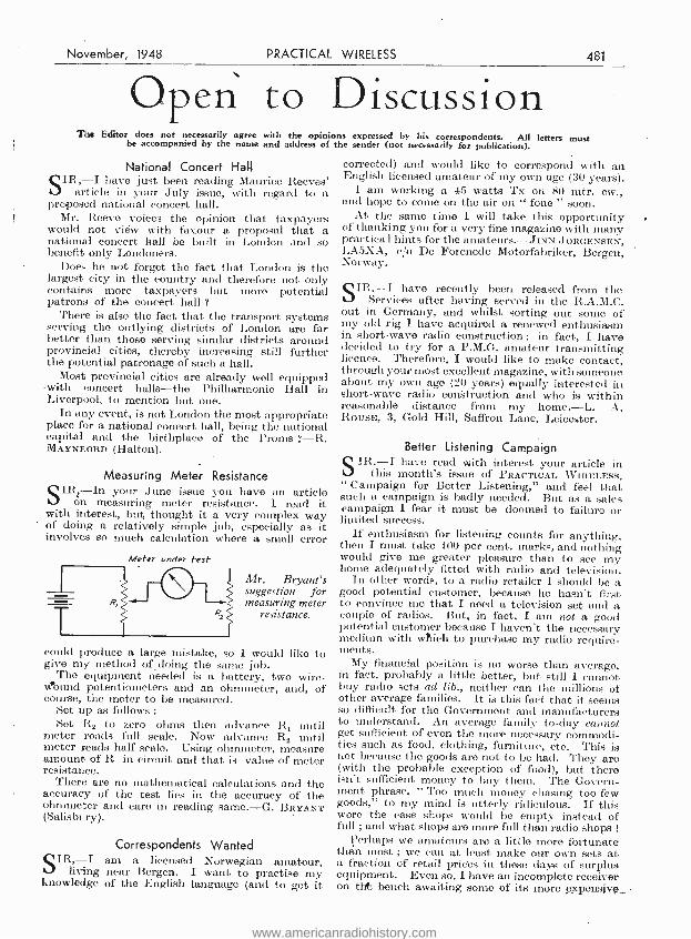
November, 1948 PRACTICAL WIRELESS 481
Opens to Discussion The Editor does not necessarily agree with the opinions expressed by his correspondents. All letters must be accompanied by the name and address of the sender (not necessarily for publication).
National Concert Hall SIR, -I have just been reading Maurice Reeves'
article in your July issue, with regard to a proposed national concert hall.
Mr. Reeve voices the opinion that taxpayers would not view with favour a proposal that a national concert hall be built in London and so benefit only Londoners.
Does he not forget the fact that London is the largest city in the country and therefore not only contains more taxpayers but more potential patrons of the concert hall ?
There is also the fact that the transport systems serving the outlying districts of London are far better than those serving similar districts around provincial cities, thereby increasing still further the potential patronage of such a hall.
Most provincial cities are already well equipped with concert halls -the Philharmonic Hall in Liverpool, to mention but one.
In any event, is not London the most appropriate place for a national concert ball, being the national capital and the birthplace of the Proms ? -R. MAYNEORD (Halton).
Measuring Meter Resistance SIRj In your June issue you have an article
on measuring meter resistance. I read it with interest, but thought it a very complex way of doing a relatively simple job, especially as it involves so much calculation where a small error
T
Meter under test
Mr. Bryant's suggestion for measuring meter
resistance.
could produce a large mistake, so I would like to give my method of doing the same job.
The equipment rieeded is a battery, two wire - vJound potentiometers and an ohmmeter, and, of course, the meter to be measured.
Set up as follows :
Set R2 to zero ohms then advance Rr until meter reads full scale, Now advance R2 until meter reads half scale. Using ohmmeter, measure amount of R in circuit and that is value of meter resistance.
There are no mathematical calculations and the accuracy of the test lies in the accuracy of the ohmmeter and care in reading same. -G. BRYANT (Salisbury).
Correspondents Wanted SIR, -I am a licensed Norwegian amateur,
living near Bergen. I want to practise my knowledge of the English language (and to get it
corrected) and would like to correspond with an English licensed amateur of my own age (30 years).
I am working a 45 watts Tx on 80 mtr. cw., and hope to come on the air on " fone " soon.
At the same time I will take this opportunity of thanking you for a very fine magazine with many practica 1 hints for the amateurs. -JINN JORGENSEN, LA5XA, e/o De Forenede Motorfabriker, Bergen, Norway.
SIR, -I have recently been released from the Services after having served in the R.A.M.C.
out in Germany, and whilst sorting out some of my old rig I have acquired a renewed enthusiasm in short -wave radio construction ; in fact, I have decided to try for a P.M.G. amateur transmitting licence. Therefore, I would like to make contact, through your most excellent magazine, with someone about my own age (20 years) equally interested in short -wave radio construction and who is within reasonable distance from my home. -L. A. ROUSE, 3, Gold Hill, Saffron Lane, Leicester.
Better Listening Campaign STR, -I have read with interest your article in
this month's issue of PRACTICAL WIRELESS, " Campaign for Better Listening," and feel that such a campaign is badly needed. But as a sales campaign I fear it must be doomed to failure or limited success.
If enthusiasm for listening counts for anything, then I must take 100 per cent. marks, and nothing would give me greater pleasure than to see my home adequately fitted with radio and television.
In other words, to a radio retailer I should be a good potential customer, because he hasn't first to convince me that I need a television set and a couple of radios. But, in fact, I am not a good potential customer because I haven't the necessary medium with which to purchase my radio require- ments.
My financial position is no worse than average, in fact, probably a little better, but still I cannot buy radio sets ad lib., neither can the millions of other average families. It is this fact that it seems so difficult for the Government and manufacturers to understand. An average family to -day cannot get sufficient of even the more necessary commodi- ties such as food, clothing, furniture, etc. This is not because the goods are not to be had. They are (with the probable exception of food), but there isn't sufficient money to buy them. The Govern- ment phrase, " Too much money chasing too few goods," to my mind is utterly ridiculous. If this were the case shops would be empty instead of full ; and what shops are more full than radio shops !
Perhaps we amateurs are a little more fortunate than most ; we can at least make our own sets at a fraction of retail prices in these days of surplus equipment. Even so, I have an incomplete receiver on tilt bench awaiting some of its more _expensive_
www.americanradiohistory.com
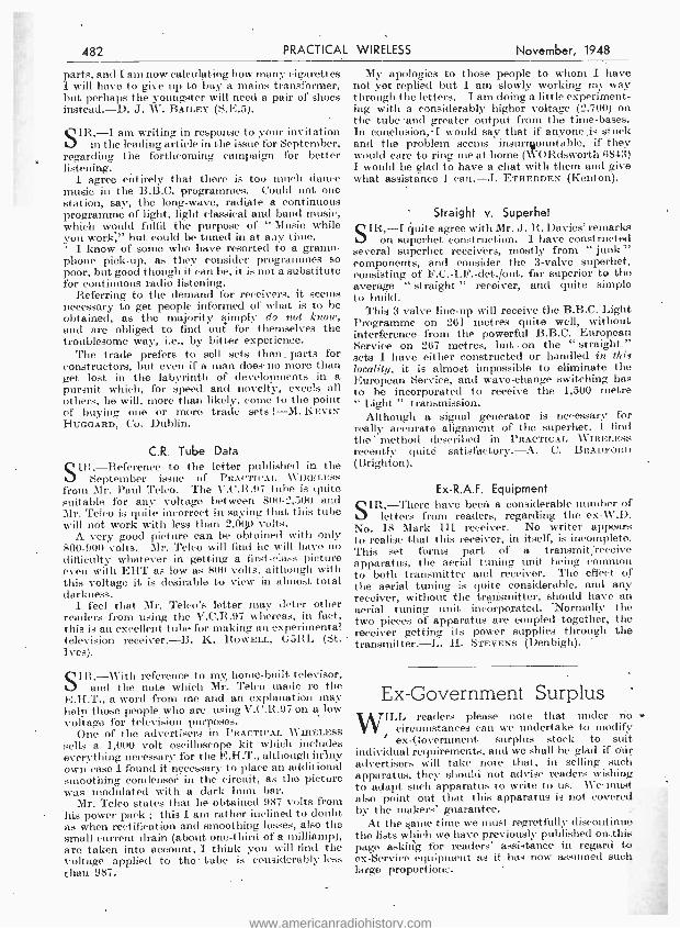
482 PRACTICAL WIRELESS November, 1948
parts, and I am now calculating how many cigarettes I will have to give up to buy a mains transformer, but perhaps the youngster will need a pair of shoes instead. -D. J. W. BAILEY (S.E.5).
SIR, -I am writing in response to your invitation in the leading article in the issue for September,
regarding the forthcoming campaign for better listening.
I agree entirely that there is too much dance music in the B.B.C. programmes. Could not one station, say, the long -wave, radiate a continuous programme of light, light classical and band music, which would fulfil the purpose of " Music while you work," but could be tuned in at any time. ' I know of some who have resorted to a gramo- phone pick -up, as they consider programmes so poor, but good though it can be, it is not a substitute for continuous radio listening.
Referring to the demand for receivers, it seems necessary to get people informed of what is to be obtained, as the majority simply do not know, and are obliged to find out for themselves the troublesome way, i.e., by bitter experience.
The trade prefers to sell sets than. parts for constructors, but even if a man does- no more than get lost in the labyrinth of developments in a pursuit which, for speed and novelty, excels all others, he will, more than likely, come to the point- of buying one or more trade sets ! -M. KEVIN HUOGARD, Co. Dublin.
C.R. Tube Data SIR, -Reference to the letter published in the
September issue of PRACTICAL WIRELESS from Mr. Paul Telco. The V.C.R.97 tube is quito suitable for any voltage between 800 -2,500 and Mr. Telco is quite incorrect in saying that this tube will not work with less than 2,00)(1 volts.
A very good picture can be obtained with only 800 -900 volts. Mr. Telco will find he will have no difficulty whatever in getting a first -class picture even with EHT as low as 800 volts, although with this voltage it is desirable to view in almost total darkness.
I feel that Mr. Telco's letter may deter other readers from using the V.C.R.97 whereas, in fact, this is an excellent tube for making an experimental television receiver. -B. K. HOWELL, CSRL (St. Ives).
SIR, -« "nth reference to my home -built televisor, and the note which Mr. Telco made re the
E.H.T., a word from me and an explanation may help those people who are using V.C.R.97 on a low voltage for television purposes.
One of the advertisers in PRACTICAL WIRELESS sells a 1,000 volt oscilloscope kit which includes everything necessary for the E.H.T., although inIny own case I found it necessary to place an additional smoothing condenser in the circuit, as the picture was modulated with a dark hum bar.
Mr. Telco states that he obtained 987 volts from his power pack ; this 1 am rather inclined to doubt as when rectification and smoothing losses, also the small current drain (about one -third of a milliamp), are taken into account, I think you will find the voltage applied to the tube is considerably less than 987..
My apologies to those people to whom I have not yet replied but I am slowly working my way through the letters. I am doing a little experiment- ing with a considerably higher voltage (2,700) on the tube and greater output from the time -bases. In conclusion, -I would say that if anyone ,is stuck and the problem seems insurrgou4able, if they would care to ring me at home (WORdsworth 6843) I would be glad to have a chat with them and give what assistance I can. -J. ETHERDEN (Kenton).
Straight v. Superhet SIR, -I quite agree with Mr. J. R. Davies' remarks
on superhet construction. I have constructed several superhet receivers, mostly from " junk" components, and consider the 3 -valve superhet, consisting of F.C. -I.F. -det. /out. far superior to the average " straight " receiver, and quite simple to build.
This 3 valve line -up will receive the B.B.C. Light Programme on 261 metres quite well, without interference from the powerful B.B.C. European Service on 267 metres, but . on the " straight. " sets I have either constructed or handled in this locality, it is almost impossible to eliminate the European Service, and wave -change switching has to be incorporated to receive the 1,500 metre " Light " transmission.
Although a signal generator is necessary for really accurate alignment of the superhet. I find the method described in. PRACTICAL WIRELESS recently quite satisfactory. -A. C. BRADFORD (Brighton).
Ex- R.A.F. Equipment SIR, -There have been. a considerable number of
letters from readers, regarding the ex -W.D. No. 18 Mark III receiver. No writer appears to realise that this receiver, in itself, is incomplete. This set forms part of a transmit receive apparatus, the aerial tuning unit being common to both transmitter and receiver. The effect 'of the aerial tuning is quite considerable, and any receiver, without the transmitter, should have an aerial tuning unit incorporated. Normally the two pieces of apparatus are coupled together, the receiver getting its power supplies through the transmitter. -L. H. STEVENS (Denbigh).
Ex- Government Surplus '
WILL readers please note that under no circumstances can we undertake to modify
i ex- Government surplus stock to suit individual requirements, and we shall be glad if óúr advertisers will take note that, in selling such apparatus, they should not advise readers wishing to adapt such apparatus to write to us. We must also point out that this apparatus is not covered by the makers' guarantee.
At the 'tame time we must regretfully discontinue the lists which we have previously published on-this page asking for readers' assistance in regard to ex- Service equipment as it has now assumed such large proportion:.
www.americanradiohistory.com

L
November, 1948 PRACTICAL WIRELESS 483
CLASSIFIED ADVERTISEMENTS RATES : 31- per line - or part thereof, average five words to line, minimum 2 lines. Box No. 6d. extra. Advertisements must. be prepaid and addressed to Advertisement Manager, " Practical Wireless," Tower House, Southampton St., Strand, London, W.C.2.
Eleventh Sale.
G. R,
By Order of the Minister of Supply. WITHOUT RESERVE
STOKE ORCHARD AIRFIELD, NEAR CHELTENHAM, GLOS.
A sub -site of No. 7 Maintenance Unit, R.A.F., about 6 miles from Cheltenham. 5 from Tewkesbury and 12 from Gloucester.
J. PEARCE POPE & SONS Will Sell by Auction a largo quantity of SURPLUS AMERICAN RADIO AND
ELECTRICAL EQUIPMENT Including :
Radio Receivers, Modulator Units, Ampli- fiers. Rectifiers. Loudspeakers, Motor Generators, Dynamotors, Voltage Control Units. Transformers, Condensers. Switches. Sockets, and extensive quantities of other
radio spares, on
FRIDAY, OCTOBER 29th, 1948 At 11 o'clock punctually.
View Days : Wednesday and Thursday, October 27th and 28th, from 10 a.m. to 4 p.m., also on day of sale from 9 a.m. to 11 a.m. Catalogues, price 6d. each (postal orders
only, may be obtained from J. PEARCE POPE & SONS, St. Ablate Chambers, GLOUCESTER. 'Phone 21274/5.
AI].MISSION WILL BE BY CATALOGUE ONLY.
EDDYSTONE Short -wave Radio. Stratton and Co.. Ltd., are now in a position to consider applications for a limited number of registered dealerships in areas not already covered. Applications are invited from expert and enthusiastic Short -wave specialists at home and abroad. Write Stratton and Co., Ltd., Eddystone Works, Alvechurch Road, West Heath, Birming- ham. 31. RADIO Constructor's Catalogue. 20 -page Catalogue, packed with hundreds of items of interest to the constructor, service engineer and experimenter, plus details of our Technical Query Service. Price 4d., post free. -Cussins and Light. Ltd.. The North's Leading Radio Engineers, King's Square. York. RECEIVERS & COMPONENTS KITS IN SEMI -WIRED STATE.-Com- plete in every detail. All main components mounted and wired. Beautiful walnut cabinet,; 13in. x 8ín. it bin. deep ; M/L wave bands, 3 valves +Rec., A.C. /D.C. mains simplest instructions and circuit included 4' controls : vol. /off, tone, w /c, tuning wiring time 1 hour. £7117'6 inc. postage C.O.D. or C.W.O. and enquiries from :- Lewis Radio Kits (Dept. B2). 322. High Road, ,
Wood Green, London, N.22. Phone :
Bow 5997. GLEN RADIO for quality components at lowest prices. Send for lists.-411. Union St., Aberdeen. BRAND NEW ex- Government Stock at Really Keen Prices. 6 valve Beacon receiver. 6SÁ7, 6SK7, 6SF7. 2 -25L6, 200 -400 k /cs., 44 x 4i x 7}. easily convertible, 50/- : 16 1- way switches in panel case, 2/6 : 4 valve amplifiers, 2 705, 7F7, 7Y4. 10 /- : 2 valve pre amplifier, 6SL7, 28D7, 12/8: 2 valve battery amplifier type A1134. QPP output, packed in wood case, 15,'- ; new mains transformer, 350 -0 -350 80 m.m., 6.3 v. 3 amps 5 v. 2 amp. half shrouded, 22./6: 24 volt relay unit, 4/6 : ex -W.D. VR91 equiv. EF50. 8/6 ( good quality lead and phone jack. 1/8 t low impedance headphones and. jack. 3/- : Bendix Radio Compass Units, No. B.C. 433 G, with control box, limited supply. £4 10s. modulator units, B.C. 456 B., 15/- ; B.C. 455 B. short wave receiver, complete with dynamotor. 55- : 16 m.m. gun type camera, £2 7s. 6d. compressors with driving spindle, £1 5s. compressors without driving spindle. 15/- Suppressors, 1/- each ; we are stockists to Avo. Pullin meters. Connoisseur, Goldring pickups, etc., Wharfedale, Goodmans, Bryce, Elstone, Eddystone, Raymart, Tungsram, H.V.A., etc. Carriage 7d. Orders over 20/- carriage paid. The Super Radio Company (Bradford), Limited, 39, Bank Street, Bradford, York- shire.
SPECIAL OFFERS,- 1155s, as new. 10 valve, £7, few only. Power Pack to suit as per W.W., inc. 6F6 output, £5/5.0. 10 mfd. 1,000 v.' T.C.C. block paper cond., 7!6. Oak Ext. Speakers, excellent value, Trugnol v.c. 8in. Grampian unit, 35/ -. Cabinet only, 15/8. Unit, 16/6. V.C.S., 6/ -. All goods guaranteed. Post paid over 10 / -.-G. A. Taylor, 125, Manchester Rd., Denton, Manchester. BEST VALUE yet. All Brand New. M.C. Phones and Mic. Boxed, 5/6. Super American Throat Mies, Boxed, 4/ -, Type 26 Converters, 37/6. 350 -0 -350 6v, 5v, Mains Transformers, 90 m,'a, 19/ -. .5 mfd. 3,500v. Condensers, 5!- each. ,1 mfd, 2,500v. (*bnd 2/-. Boxed, 807's at 10 /- : 504G at 9/- : 524, 8' -. R107 Receiver, perfect, £16/10/ -. 6SN7GT Valves at 6/ -. lin. M.C. Speakers at 15/6. 1 mfd. 600v. Aerovox Condensers, 9,6 doz. BC348 Receivers, £16/10' -. Ceramic Coil Formers, 40n, it 2ín, diam, threaded, 4/8. Complete Vibrator Packs, 12 volts input, 200v. at 70 m/a smoothed D.C. output. 21d. stamp for many other super buys. -Radio Constructors. 28, Spital Hill, Sheffield. Direct Agents for Labgear and Denco. Enquiries welcome. Trade supplied. EVERYTHING for the wireless con- structor. Send stamp for price list. - H, Tabner, 118. Nightingale Road, Hitchin, Herts. ELECTRO CONDENSERS. -500v. 8 mfd., 31- ; 4 mfd.. 2 8. Mains Transformers. 27/ -. All new stock. Send for cut -price list to 384, Two Mile, Kingswood, Bristol. SELENIUM Metal Rectifiers. -Any output up to 24 v. 5 a., 16 discs, 41ín. dia., 20'- each. List No. 2 now ready : hundreds of surplus aircraft items. Send ld. S.A.E. to :- K. R. Whiston, 22, Hall Street, New Mills, Stockport. M('RI receiver complete as new. Offers. 22, Iveagh Avenue, N.W.10. TESTED GOODS, -Volume controls. 1,8. MC Mikes wtwitch, 5/ -. Dual -range crystal coils w!circuit, 2/6. 5in. P.M. speakers, 10'11: 8ín., 17/6. Multi -ratio speaker trans., midget. 3/6. Intervalve, 2.6. Mike, 1!6. Rotary switches, most types, 1'8. List 2.d. Carter's, 67, Bell Lane, Marston Green. Birmingham. BC442A Metered Aerial Relays, 8' -. I Metal Rectifiers, 600v. 30m.a., 3'- : 90v. 20 m.a., 21 : 6 -12v. la.. 3' -. Loctals, 1.4v., 1299, 1291. 1LN5, 1LC6, 58. Headsets, LR with Mic., 6'6. L.F. chokes, 300 ohm 1001/1.a., 4/8. Wirewound pots, 12 ohm. 5 amp., 200 ohm. .5a., 6 / -. Pyrex lead -ins, 1/ -. Bakelite Pulleys. 9d. Crystals, 4 -8 m /cs, 5/- ; 7.010, 7,6. Mlcroammeters, 0 -100 21in. uncal., 10 1-. Condensers, 30mF 100v., 1'6 ; 0.1mF 1.000v., It- : 001mF 500v., 9d. Modulator Units, BC456A 3v., 17/6 : TU207A Klystron, 52/8 :
S.F.F. (13 valves), 22/6. Yaxley's 3 -pole 3 -way 3 -bank, 3 6 : 4 -pole 2 -way, 2/6. Panel lampholders, 1 3 : shaded. 1/9. BC933G Control boxes. 76. 2ín. MC 0 -1 Ammeters, T8 1 3ín. MI 20v., T6. Valves : EH34, SP91, SP61, 3/6 : 6SN7,6SL7, KTW62, 5R4GY, 6' -. Venner Clockwork Impulse Generators, 15/ -, Rx Unit 194 (VHF). 4 valves, 12 6. C.W.O., S.A.E. all enquiries,- Benson, 308, Rathbone Road. Liverpool, 13.
SHOP BY POST. We pay all carriage, packing and postage. High grade ex- Govern- ment and new goods of the highest quality by all leading makers. Send 21d. stamp to -day for our bargain list. Here are a few examples of the value we offer : Meters 0 -350 or 0 -500 mA, H.F., 3/11 : 0 -500 micro amp. scaled 0 -15, 0 -600 volt, 6/6 : Weston Backward Reading 0 -1 mA. scaled 0 -120, make ideal " S " meter. etc.. 4/11 ; G.P.O. headphone and mie set, 2/11 24 volt motor approx. I h.p., 5/11: 230 v. A.C. I h.p. int. rating, 79/6 : Twin. tough rubber - covered cable, 5/- doz. yds.: R.A.F. carbon microphones, 2/6 : rectifier units include transformer and metal rectifier, 230 volt in 200 v. 250 mA. out, 451- : 4 -gang 0005 tuning condenser with trimmers, all new in boxes. 616 : J. B. slow motion drive with knob and dial, 2 9 ; wave -meter type 1117, complete with matched valves and charts in transit case, 75/- : battery eliminator 230 volt A.C. in 120 v. 30 mA. stabilised out all new, 35, - : camera control units make time switch, etc., for 12 or 24 volt A.C: or D.C.. 20/- : 8B series radar units, include 6in. tube VCR97, 8 valve, etc., all new. 70'- ; receiver units contain 12 volt motor generators, 11 standard valves, resistances, condensers, relays, etc., 39/8. We are agents for. Woden transformers and electronic equipment and invite your enquiries. Waltons Wireless Stores (Mail Order Dept.), 203, Staveley Road, Wolver- hampton, or (Callers Only), 48, Stafford Street. Wolverhampton.
POST -WAR RADIO at pre -war price 1
The N.R.S. " Fidelity " 5 -valve A.C. /D.C. Medium and S.W. Superhet, neg. feedback, attractive 2- colour plastic cabinet, . com- plete, guaranteed, 91 Kos., incl. tax and carr. Exhaustive Constructional Manual en- abling even beginners to build a powerful 5 -valve 3- waveband A.C. Superhet of excep- tional power and range, price 5/- : all parts available, inc. figured walnut cabinets. A.C. /D.C, model, too. Also our ever -popu- lar T.R.F. 3- valver (mains), complete kit with cabinet, £8/10' -. W'e Now Announce 4 -valve All -dry Battery version of our " Overseas 5," by popular request : Con- structional Manual, 3/ -. The N.R.S. Audio Amplifier for A.C. 200 -250 v., 4 watts undistorted, 3 valves, pickup and tuner inputs (volts available), volume. tone and neg. feedback controls ; com- plete, tested, £5/19,6. Send 2íd. now for leaflets on. above and special P.W." Bargain List. Heater transformers, 6.3 v. 1.2 amp., 12/6 (11/ -). Universal type tapped . 4 v.. 5 v. and 6.3 v., 12 watts, 17/6. Iron -cored' I.F's., 465 kc /s, standard or midget, preci- sion adj., 13/6 pair. P.M. Speakers : E.M.I. 5in., 11/6 Goodmans, etc., 64ín 19/- t R.A. 81n., 21/- : Rola l0in., with trans., 25/ -. Standard output trans., 6/6 multi- ratio, 86. Wharfedale Golden, 3 and 15 ohms, 75/ -. Gramophone Equip- ment : A.C. gram, motors, gin. table, 75/- : Collaro, ditto, with 12ín. table, variable speed, 118/4 t Collaro motor /pickup /auto- stop combined unit, A.C., £9 t A.C. /D.C., £12'18/9, both 5 Carr. Plessey super quick - action A.C. Record Changers, with mag. pickup, £18/9!6. 5;- carr. Ex -Gov. Valves : tested 100 per cent.. 6J5G, 6J5GT, EBC33, EF50, 56 (5/ -). Brand New Valdes, best makes
CH35. 15D2 6X5, 5Z4. $ E)
6K7, 6K7G, 8Q7G, 6V6, 6V6G, 6F6G 6 6N7, 6N7G, ECC31, 6SN7GT, 6J7G, KT33C, FW4'S00, 5114G, U52. 10'- (9' -) ; 6L6. 6L6G,
_12'6 (12' -) : PX25. 15/ -. Matched pairs gladly supplied. We specialise in Instru- ments by mail order. 21d. for advice and new AVO catalogue. TERMS : C.W.O. or C.O.D., bracketed prices lots of three, postage extra under £5. N.R.S.. 102, Parkhill Rd., London, N.W.3. Tel. : Gulliver 1453, "TELEVISION.' -Build your own re- ceiver in 24 hours, unit -construction (not ex- Govt.). Everything provided, including 10 blueprints (practical and theory), also step by step instruction guide. All parts Can be supplied separately. You must use our new improved sound and vision coils Circuit supplied. We supply every- thing Radio and Television. A personal service to the home constructor. Send Id. stamp now for free literature. All en- quiries to the office, T -H Products, 92, Leathwaite Road, Clapham Common. S. W.11, Phone : BAT. 4889. ALUMINIUM chassis and panels, any size, plain or punched for valveholders, meters, etc. Finished bright grey cellulose or black crackle, from '3/9 each. Precision built superhet coil packs, 3 waveband, aerial and oscillator type, 37/6. ditto with H.F. stage, £3. 465kc. IFTS iron cored, 15/6 pair. Data sheets on request. Prompt Delivery. EAD, 13, Bence Lane, Darton, Barnsley, TELEVISION KITS and Complete Chassis. Amplifiers, 5 -500 watts. Feeder Units. The complete range of Denco Products, including the latest CT7 Turret (with R.F. stage). Also 5 and 10 waveband Gram Chassis covering 3 -60 me /s. and 150 -1,500 kc /s. S.A.E. for leaflet of single items, or illustrated catalogue, price 9d. to Masons (PW) Wivenhoe, nr. Colchester. HARRY JAMES PRODUCTIONS, 270, Leith Walk, Edinburgh, 8. Mail Order Specialists, C.O.D. or Cash with Order. Electrolytics, new, not W.D: surplus B.I. Hunts, etc., 8 mfds., 3/2 ; 16 mfds., 5/3 16-8 mfds., 6/2 t 8 -8 mfds., 8/- ; 4 mfds., 2/9 25 mfds., 25 v., 2/- t 50 mfds., 50 v., 2/9 T.R.F. Chassis, 3/8. T.R.F. Coils, M. & L. 7/9 pair. Condensers, 0.1, 0.01, 0.05. 500 v. 8d. each. Variable 2 gang, 0.0005, 12/ -, with Trimmers, 13/8. Loudpeakers, 5in. P.M. 191 : 61in. energised 1,000 ohms, 29/6. Bin. P.M.. 25/ , Volame Controls, Long Spindle, W /S, 5/6 : L /S, 3/6. Mains Transformers. 350 -0 -350, 6.3 v. and 5 v. or 4 v. Heaters, 30/ -. Output Multi Ratio, 9/ -. Valve Holders 5 pin, 7 and octal, 7d. each. Amphenol type. 9d. each. Voltage Droppers, 0.2 amp. 1,000 ohms, 3/9 : 0.3 amp. 800 ohms, 4/9. Line cord, best quality, 0.8 amp. 3 core, 9d. per ft. Special Offer. 0 -1 milliamp. metres. suitable for multi meters, etc., price 121. Valves C.O.D. Large stocks of British and American types. Enquire for anything in Radio. S.A.E. for lists.
www.americanradiohistory.com
484 PRACTICAL WIRELESS November, 1948
97.6, C'IIR(:ING SWITCHBOARDS.I 13v. 32v., 500 and 1.260 watts. volts. amps., cut -outs, fuses, resistances. etc., 4 take -offs. superb unit, in case ; or send £5 carriage paid. 75'-. DYNAMOS. 24 volts, 1.000 watts, 9in. by 7in., lin. spindle, or send 80- carriage paid. 75f -. 230v. l 50, 155 h.p. ELECTRIC MOTORS. incorporating 1,260 cycle converter, or send 80 - carriage paid. 58' -, MAINS TRANSFORMER SWITCH- BOARDS, 230v. A.C. to 12v., 5 separate take -offs, complete distribution panel. all switches, fuses, amps., etc., brand new, or send 60 - carriage paid. 55-. ELECTRIC MOTORS, 12c. and 24v.. 1 4 h.p.. 4in. by 4in., with lin. spindle for drive, beautiful job, or send 60'- carriage paid. 45 -. DYNAMOTOR UNITS, containing 12v.. 24v., 130v.. and 300v. D.C. dynamo, or suit- able as 6v., 12v.. or 24v. motor. approx. I h.p., llin. by 5in., with spindle to take small grindstone, mop. etc.. also contain adjustable 24v. cut -out. 12v. automatic voltage control, smoothing condenser, resistances. and many other extremely useful fittings, beautifully made, or send 50- carriage paid. 38 - RADIO WAVEMETERS, adjustment dial,
,
350 -370 Mc s., beautiful instrument in case. or send 40.- carriage paid. Host other valuable equipment. Lists free. Benmotors, Summerley ,Street, Earlsfield, S.W.18. WIM. 3833. (10(Lvds. S. Rly. Electric Line ; 10 minutes Wáterloo.) FREQUENCY METERS. No. 221, £826. Frequency Meters No. 906. £2 12 6. Re- ceiver No. 1066, £1:7:6. Signal Generator No. 196. £1 ;7;6. Radio Compass No. B.C. 433. £32 6. Receiver No. 966. £1. Trans- mitting Tuning Units No. 265. 2500 k /cs., 5 -. Radio Voltage Control Panels. 80 volt A.C.. 7,6. Ferranti Output Test Set (new). Type 2, £1'26. Indicator Unit Cathode Ray Tube (new), £1 7'6. Master Contactors (Precision winding clock movement). 12 6. Rectifier Power Units (new). Type PPi104 A.PT5. £12 6. Cash with order, carriage paid. -St. Mark's Garage, St. Mark's Street. Bolton. 'Phone 2632. TELEVISION EXPERIIIF;NTERS.-Old- church Laboratories have everything you need. For those using the V.C.R.97 and similar tubes, we have introduced a special E.H.T. transformer. delivering 2,000 v. l l m a. Price. £1. V.R.91 and V.R.65 valves, each 5! -. Guaranteed perfect. Specified components for Electronics " televisor. E.H.T. trans.. 65!-. Heater and H.T. trans., 75'- Focus coils. 33' -. Adjustable scanning coils, 35, -. Complete set of specified dust cored coils, 15' -. Sound chassis, 18 9. Time base chassis, 18;9. Vision chassis, 22/6. Our T.S.74 conversion data still in great demand. Price, £1 for 4 blueprints and instruction booklet. Our " Versatile Transformers." as previously advertised, still available, at 7/6 each. Send 2!d. for our latest list. L. P. Dismore, 52c, Oldchurch Rd., Chingford, 5.4. KIT SETS WIRED.- Apparatus con- structed to your design. Any receiver serviced. Send diagram or set for quota- tion, to F. A. Sharp & Sons. 53. Weedington Road, Kentish Town, N.W.5. 'Phone GUI, 1759. FLUORESCENT LIGHTING, 80 -watt choke -capacitor unit, 220 -240 v. A.C. holders, glow starter, ready to install, less Oft. tube, 4716. carr. free. -Malden Trans- former Supplies, 39, Malden Road, New Malden. Surrey. SELENIUM REC'T'IFIERS, 250 v. 40 in a, 21 ea., 24'- doz.: 60 We, 3'6 ea.. 33 - doz. ;
75 ma, 41 ea.. 42'- doz. : 100 m'a, 5'6 ea., 54- doz. ; 19 v., 1 a., 5'6 ea. : 12 mfd. 50 v., bias elecs., 13 ea., 12'- doz. Aluminium chassis. 16 gauge, 10- 51- 2ins.. 36 ea. : 11 -6 -2t. ins., 310 ea. ; 12- 8- 2/ins., 4'9 ea. ; 16 -8 -2!. ins., 5 /10 ea. ; 20- B- 211ns.. 7,6 ea. Mallory vibrators, 12 v. 4 pin, 4 6 ea. Tuning con- densers, small, .0005 mfd. 2 gang (ceramic). 3 9 ea. Mains transfrs.. 200.250 v., screened primary, 350-0-350 v. 80 m'a, 6.3 v. 3 a., 5 v.2 a., semi- shrouded, drop -through type, 19 6. Midget output transfrs.. 40 :1, 35 m a, 3'- ea., 30'- doz. Rola loin. P.M. Speakers, 27'6 ; Celestion Bin. P.M., with trans., 19B ea. Iron dust cored I.F. transfrs., 465 k. /cs, 8 6 pr. Dial and drives, complete with attractive fully station named 3 -wave dial, in 3 coloured ivorine, S.M. drive. pointer, glass and handsome bronze escutcheon, 9,9. Wire wound pots, 10 k., 20 k.. 25 k., 2'3 ea.. 21/- doz. Send 21d. stamp for bar- gain list, for trade. C.W.O. or C.O.D. Postage extra. Radio Supply Co., 15, Queen Square, Leeds, 2.
AMERICAN ABK SPARES KITS: Containing 32 valves, 6SH7, 6H6, 7193. a motor generator suitable for 6 v. or 230 v. A.C. mains 50 cys., Silver plated aerial, switches, relays. res. and cons., etc., etc., 148 items in all and individually boxed and BRAND NEW in magnificent heavy plywood case finished gray enamel and fitted hinged lid with clasps and provision for padlock. At £5 per kit, carr. paid,-you can't go wrong. American Radar Spares Kits. containing 61 valves, 955, 956. 6AC7, 5U4, 6V6, 6SN7, 2X2 2C26. 90ft. Co -ax. cable. meter leads, test leads and other cable and wire, also nuts. bolts, washers, screws. various hardware and technical manual TM 11 -1159 all in water -tight plywood case, with valves separately boxed: £12 each carr. paid. ABK kits of plugs and sockets, including standard 3 -pin 5 a. mains sockets. and silver plated aerial in original sealed wood crates, 1316 each, carr. paid. 1132A UHF receivers. complete with valves, and in good condition. £4 5'- each, plus 10;- carr. and £1 dep. on crate. Last month's items still available. We have a complete range of Gov. Surplus components, mostly new or as new, and all guaranteed perfect. When building that new receiver send us your lists for a quotation, you will be surprised how much you can save. For all RADIO, ELEC. and SCIENTIFIC require- ments remember the name that stands for fair dealing. H. English, The Maltings, Rayleigh Rd., Hutton, Brentwood. Essex.
FRITH R ADIOCR AFT, LTD.. Leicester. offer : Denco frequency sub- standard harmonic generators, type DESIA giving spot frequencies every 100 k cs from 200 ire s to 50 me s, main operated. complete with 6V6, 657. 5Z4, 100 k es and 1,000 k es crystals. brand new with maker's instruc- tions, £6 6-. carr. paid. D.C. A.C. rotary converters. input 24v. 9a.. output 230v. 50 cis, 100 watts. brand new in carrying caSe, present cost over £30, our price £3 15s., carriage paid. 4 -gang tuning condensers .0005, modern, medium size, ceramic insulation, 5 -, plus 9d. post. Luxury lightweight headphones by Western Flectric U S A fitted cushion earpads, 240 ohms. 15,'- plus 9d, post. B.I. electrolytic condensers, wax carton 500v. working, brand new stock, 4 mfd., 33 :
8 mfd., 3.6 : 8 +8 mid., 4'9. 8 +16 mfd., 6 3. Vertical metal cans, 16 mfd. 500v., 5. -. Dozen lots, assorted, post free. IF transformers, standard small size, adjustable dust iron cores, 455 k'cs, 7/8 per pair --6d. post. Latest lists free on request. Satisfaction guaranteed or cash refunded without question. -Frith Radiocraft. Ltd., Leicester. 'Phone 58927.
Tràde
ed. All
REPAIRS to loud -speakers. Cones, coils fitted. Fields altered. rewound. Output transformers, clock coils. No mains trans accepted. Prices quoted. Satisfaction guaranteed. -L. S. Repair Service. 49. Trinity Rd., Upper Tooting, 5.W.17. Closed Saturdays, Phone : Balham 2359.
AMAZING BARGAIN. 9'6 complete kit parts for 3W.B. superhet coil pack including Yaxles'. coils, chassis, tr immers etc. Mains trans.. 16/6. Drop pers. 2r8. Send for cheapest list in England. -- Sussex Electronics, Ltd.. 4, Upper Be vendean Avenue, Brighton. Tel. : 9446.
COPPER WIRES, enamelled, tinn ed, Litz, cotton, silk covered. All gauges. S.A. screws, nuts, washers, solderin g tags. eyelets. Ebonite and laminated bakelite panels and tubes. Paxolin coil formers. Tufnol rod. Crystals, permanent detectors, headphones. Latest radio publi cations ;
full rango available. List S.A.E. supplied. -Post Radio Supplies, 33, Bourne Gardens, London. E.4. REWIND SERVICE.-Armatures, Gram. motors, Vacuum Cleaners. Drill and all small motor Transformers -Field s Pick - ups, Speakers -New Cones and Spee ch Coils fitted -New Vac. Cleaners suppli work guaranteed and promptly executed. Special terms to the Trade. Send S.A.E. for Price List and Radio Spares. - Co., 261 -3 -5, Lichfield Road, A ston, Birmingham. 6. NATIONAL Radio Service and Television Company, leading Radio and Te levision repair organisation in the count ry. All makes receivers, amplifiers, etc. Rewinds to transformers, field coils, armatu res, etc. New cones fitted to loudspeak ers. All types British and American valves stocked. Immediate service, collection. e tc., any district. -63, High Street, N.W.8. Prim - rose 6725.
RECORD PLAYING DESKS fitted with B.S.R. electric gram motor and pick -up. A.C. mains, £8 Ss., including tax. Below - Quality Speakers : New Rota. G12 plus. £8 10s. ; Goodman 12in., £6 15s. : Good - mans Axiom 12, £8 8s. ; Kola or Elac, loin., 30 - : 8in.. 2343. Pifco Radiometers, 0 -6v.. 0- 240v., 0 -30 mA. A.C. or D.C. and circuit test, 25' -. Avominor D.C., £4 4s. Avominor A.C.'D.C., £8 10s. Taylor 120A (1.000 opv), £8 8s. Electrolytics, best makes only, 8 mf., 4'- : 8-8. 6 6 ; 16 -8. 8 ;6. Many other lines, all brand new stock of best quality. Send S.A.E. for list. C.W.O. or C.O.D. (C.W.O. only for 121n. speakers, too heavy for C.O.D.). Carriage paid over £1. -Homer and Newey (Radio), Ltd., Dept. P, 211, Queens Road, Smethwick, Staffs. M.S.S. RECORDER, brand new, latest model, with matching transformer : B.S.R. 30 watt amplifier and selection of blanks. cutters, etc., cost £140, offers. S.A.E. for details. -Box No. 165. MAGNETOPIIONE, studio type tape recorder, German manufacture, new con- dition, precision made instrument, suitable for recording, or broadcasting studio work, etc. -Details on request. offers, Box No. 166. SIGNAI, GENERATOR, mains driven, 40 -2900 m., built to P.W. specification, using new components ; requires calibration. £7,10. A.C. Gram. Motor with P.U. £4 /10 -Box. No. 1,67. SALE.- Copies " P.W.." " Aeroplane." " Flight." List S.A.E.- BM;THJC, London, W.C.1. 125.17.s, 12S117s, D1 (Peanut), 5'- each. - Wilson. 13, Carter Street. Burnley. SALE.- Avometers, Avominors Speakers, Valves, etc. Big reductions: List S.A.E. - Young, 134, Old Shoreham Road, Southwick, Sussex. TAYLOR. -65B A.C. sig. gen. and acces- sories. New, £10 10s. Strad 5 valve 3 band A.C. S.het., unused, £12.-71, Crowther Rd.. London, S.E.25.
TUITION MERCHANT NAVY. -Here is an oppor- tunity to train yourself as Radio Officer for merchant ships. The big liners are open to you, but you must first qualify for P.M.G. Certificate. Established 30 years, we can put you through in the minimum of time. Prospectus from Director, The Wireless School, 21, Manor Gardens. Hollo- way, London, N.7. 'Phone: ARC 3694. THE BRITISH' NATIONAL RAD)( SCHOOL (Estd. 1940) for New World Ideas and Old World Ideals ! The Urge to Serve and the Knowledge How ! Home Study Specialists with the Personal Touch. Radio, Radar. Maths., Physics. The B.N.R.S. Four Year Plan covers the full syllabus of A.M.I.E.E., A.M.Brit.I.R.E. and City and Guilds Radio and Telecommunications Exams. Six months' trial period without obligation to continue. Day classes in all subjects, including P.M.G., recommencing shortly. Send for free booklet to :- Studies Director. British National Radio School, 66, Addiscombe Road, Croydon. (Phone : Addiscombe 3341.) WIRELESS (sea and air) TELEVISION. Broadcasting. Radar, etc., offer tremen- dous opportunities. Students, both sexes. age 14 upwards, trained for appointments in all branches of Radio. Low foes, boarders accepted. 2d. stamp for pros. - Wireless College, Colwyn Bay. AMATEUR Radio Transmitting Licence. Postal Course of Instruction in the theory of Wireless Telegraphy covering all require- ments of the syllabus for the examination. Apply British School of Telegraphy, Ltd.,' 179. Clapham Road, London, S.W.9. (Estd. 1906.) THE INSTITUTE of Practical Radio Engi- neers have available Home Study Courses covering elementary, theoretical, mathe- matical, practical and laboratory tuition in radio and television engineering ; the text is suitable coaching matter for I.P.R.E., Service entry and prdgressive exams.; tuitionary fees at pre -war rates are moderate. The Syllabus of Instructional Text may be obtained post free from the Secretary, Fairfield Road, Crouch End, N.8. RADIO AND ItADAIt.- Training for a career in Air or Marine Services as Radio Officer, Radio Officer, Mechanic, or Engi- neer. Residential and non -residential Courses at the Radio and Radar School of Britain's Air University. Enquiries to the Commandant, Air Service Training, Ramble, Southampton. Telephone, Hamble 2185.
www.americanradiohistory.com
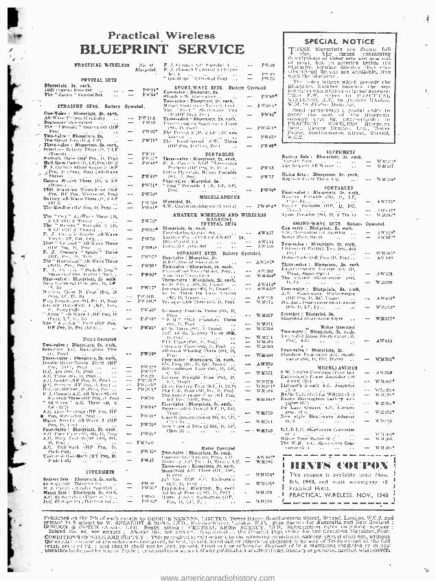
1 I
i
Practical Wireless BLUEPRINT SERVICE
PRACTICAL WIRELESS Vu, aJ P. J. Canon'.. I.C. eo,prrhet 4 - PW59 Bl ieprinr. P. J. C'anon's tnirernal £4 S:per-
hl t)ual(tonc " ' ver =al Four - í'H 73
SHORT -WAVE SETS. Battery Operated Cne -valve : Blueprint, 2a. Simple +.W. Doe-\ nber .
Two -valve.: Blueprints, 29. each. Midget SI.nç -u: ate -1 ,o (D, Pen) The " Fleet " Shen -,11,10 'NIo
tD (HP Pent. Poo FW3l A Three -valve : Blueprints, 2s. each,
F Wes 100 Nelilw'uI,'a Shoal-WAS a'three PR'93
(St :, D, pow) The Pn.rect 3 (D, 2 LP (RC and r m,)
Pß'78 The 14005 -screed 5,1V. Tln'es (LF Pen, 1, (I'' Ii, Pro) ..
FWIO PORTABLES Pwa7 Three -valve o Blueprints, Ss. each. PhY4e F. J. l'earn's i:1,1" Three -mire
Portable IIIY lv',1,1,, Penl Parr. Flywe,gl,t Midget Portable
CRYSTAL SETS Birwpelnts, la. (tech. 19'3715 vital Reeeivre .. ., . - PW71e The " Janior " Crystal Set .. - PW94)'
STRAIGHT SETS. Battery Operated. One -yalee : Blueprints, 2s. each. ah-pate Cn(pen (Pentode) .. Beg(nnr_e' une- velrrr The " Pyramid " une- valvcr (HP
Pen) Two -valve : Blueprints, 2s. l'he Signet Two (11 4 1 13)
Three -valve : Blueprints, 21. each. tiete, t,oe, Battery 'Three (U, 2 1,F
(Tranhl .
Bumrnit Ihrre (HF Pen, D, Pen) Hall -Men: l'adet (i), T,F,Pen ( Ill')) F. J. Carom' Silver Souvenir (HP _J Pen, D (Pen), Pen) (All-Ware
Three) Mined Mb,ret Three (D, 2 LF
(Trn r1 1038 $o.ot ne Three -Four (HF
Pen, 14F l'en, Wca(eetor, Pete) Battery All -Ware Three (D, 2 LIP
The MonEfor (TIF Pen, D, Pen) ., The "Cot All -Wavy Three (D,
2 Li" (tat 4 Trans)) The " (cupide" Straight 3 (D,
2 LP 110,0 .v Tra,,,)) F. J. trams,', Oracle All -Wave
Three( rl(i, Del., l'en- .. 193í " 'ir hand " .ill -Wave Three
(HF l'on, I), Pen) F. J. CtrentuM "Sprite" Three
(11 P, h'v, D, 'l'et) The " Hurricane " All-Wave Three
(51114, Pen, l'en) F. J. Ca: nm'a " t'ush- BnLton
Three I hN Pen, D (Pro,. Teti.. Four -valse : Blueprints, 2s. each Neu universal Four (SG, D, LP
t. 1H No(lean Close B Four (SO, D
CND. 1,10', Cl. B) Fury Four Soper (SO, (4(1, I), Pen) battery )kali :Mark 4 (1£P, Pen,
D, Push- lull) " A on( e " All-Wave 4 (fil Pen, D
(Pen), LP, CI, L') The " A.l,cir:l " Four (119. l'as
HP Pm, D, Pen (hull.. ._
Mains Operated Two-valve : Blueprints, 2s. each. Self-clone A.C. Radiogram Ileo
YD, row) Three -valve : Blueprint, 2s. each, DoableDio,le= Triode 'Three (Hie
Per, DI£l', Fe,) .. .. D.C. ,Pee (511, D. Pen) .. .. A.C. Three (1SIS, U, Pen).. A.C. header (11P ('en, D, Pow) hh). CO. Mend, till l'en, I), Pen) .. ('None Olt Pen, D (Pr,,,, )'ell ..
1 (-atom's A.C. All -Ware Silver - :air Three (III, T'en, D, Fen)
' II are ' A.C. Three (0, L I' (ItC))
A,C. 14:111 Smntnue (fiF Pen, DP fen, Wes,e.etor, Pea) .
Malus Flee, r,) All -)Vara 3 (HP Pen, I), 1en)
Four -valve : Blueprints, 2s. eaoh. A.C. Fury I ,or ,`<I:, SG, D, l'en) A.C. 1 "nt :y Cor Super (SG, SO,
A.C. Tl a{I -v:ark (1IP Iree, D, Push-1'111E
Unirered Hall -Mark (HF Pen, D, Pooh-l'ull) .. .. ..
SUPERHETS
Batter, Si 's I'm-punts. 2, each
Mains Set, 2 b. A.C. £:, sul... .. D -C. 550(01. ,.,-
o -.
Prfnn
- PW49 Four -valve : Blueprint, Bs. - FW51 " Dap " Pot table 4 (It, LF, LP,
PW53
P(555 P\VeA
PW72
PW82e
PW78
PW84
PV/3.97
P1V89
PW92
PW17
P)'.5411 PW34c
FW48
PW92.
PW90
PW19
PW?3 PR`1J PW29
P(\':15C P W :;3 B 1')538A
PW50
PW54
P11'58
PW70
r1N)a PR'341)
PW45
PW47
PW40 í'W52
rvekt PW4'I
MISCELLANEOUS Blueprint, Se. S.W. Con, roter- Adapter (t rr,iv e) -
F'Wee*
PIA-38 A.
PW91a
Pw30A
PR-03
PW9ee
PR-83
PW77
P01'iS
PW48A
AMATEUR WIRELESS AND WIRELESS MAGAZINE
CRYSTAL SETS Blueprints, la. each. Four- station Crystal Set .. - AW427 Liter rite 'I'naloo Coil for A\V437 la. 19::4 Crystal SA 1.10 -wile I 'l :Vela) Set .. .. - A it 41,0
STRAIGHT SETS. Battery Operated. One -valve : Blueprint. Ss.
ti.)'. pr,:iat t)lr- ,alter Two -valve : Blueprints, 2s. each. 1'nll- rlun,!' 'Pao SSG Ilni, lend. A t , der , 'Cu -:leer Three -valve : Blueprints, 2s. each. 1:, 5e S.I7.:1 (S14, n, '1'r, nr) Lucerne Ranger Vitt, H, t',,,,,,) ., to
e . Three De Luxe Verrioa
(SG, D, 'Arena) Transportable Three (S(1, D, Pen)
Hr,moe,y Pentode Three (SG, D, Pcn)
" %VAL" 79:34 Standard Three (5)1, D. R:u) ,.
£3 3s- Three (SU l), Trans) 10:15 Y(i 8s. Battery Three (Sa,
P'ft.'(Oreo (tree, T, Pen) .. Geri aiury- TIT rev- IAG, 1,, Wen) Alb/tare Winning 'Three (SO, D,
Pea) Four -valve : Blueprints, 3s. each. B.Y., Poor (S(i, U, RC, Trans) Self- contained lour (SG, D, LF,
I.Iwerne Straight Four (Sli, D, LP, Trans)
£5 5,,. Ita,.tre,' Four (HP, D, 2LP) The ILK. Four (SG, Su, Il, Peu) The Auto Straight Four (If Peu,
/IF Pr,,, DI'T, Pet) Five -valve : Blueprints, 2.s, each, douer -yuaii ly l'ire (2 11 P, D, lIC,
Tran,) Class R I)nadradyne (2 SG, D, LF,
Levi Urne H Five (2 aO, D, LF,
AW387
AW392 WM40pa
A W 412a A1V422
A W435 1\M271
WM337
WM351 \V'51354
W3f"71 11'01:099 15M:)93
WM400
AW3v0
WM331
WA1350 1Vmast* '%V1154
W M404
N'M:20
W M344
WM340
Mains Operated Two-valve : Blueprints, tá. each. Consoelectrir Two ( I), rem, A.C. - AW4034 E'v, Illy .I.1, Too I D, Trans', A.C. - 031298 Three -valve : Blueprints, 2s. each. Mantovani A.0 Three (HP, l'en,
D Pen) £I5 I Is. 10119 A.,', Radiogram
(HI', I', Von) .. Four- volve: Blueprinh, S:. etch Al -Me' el Four (2 SIt, D, l'en) .
Hawn Jnhi'ec Radiogram (SIP, Pen, D, L)', t').. .. ..
R'M374
W MI01
1VM:329
WM3S9
SPECIAL NOTICE THESE blueprints are drawn full
T size, The issues containing &tri pti0)10 of these Nets are 110W out
(d print, but an asterisk beside I.hr blueprint nun,bl:r denotes the, eon - 0)1,1ctíonat Veto ils are available, free with the hlueprint.
The index letters which precede I(,r Blueprint Number indicate the r. -.. _
rad(c21 in which t he de.seript )an appr:. -. Thus P.W. refers tu PHAC'l'rC ', I. WIHE0I:OSS, : \.D:. to -low(eur It- ilo'Iv,n, W. II. to l4'1,10.,' ,tfa(xrinr,
Send I preferably) c postal order to cover he cost of t):e; Bhrr;t i:.' i ale 000'5 unir lid, unacceptable PRACTICAL WIRELESS Bluer: nt; Dept George Newne Ltd., Toyer House, Southampton Street, Strand, W,C,2.
SUPERHETS Battey Sets : Blueprints, 3::, each. 'toe-its Pm:r ., -
he Request AII-41AIor -. .. - Mapiaa
,tSe
o tSu :
p er B hlrlePperr i eAte,
1 ;. B s. each. -
01001:',251 1\' 51107
N'M3ì91
PORTABLES Four -valve : Blueprints, 3e. each. Holiday /',ule Mr (SG. D, 1.1e, - Family Portable (HP', 1), ILC,
Trans) - Al1'.I 174 Ty'era Portable (SC, I), 2 Trans) - 1111347
SHORT -WAVE SETS. Battery Operated One-calve : Blueprints. Be. each. SAS I)ne -vat err for America - AN'1 29 Rona Sh',r1-warer .. ., - A \1'452 Two -valve : Blueprints, Se. each, L' It restart Bat (Cry Two (Si;, let - )'M 4'l'l' Home-a-ale Coll 'inn ID, Pen) . - - A\V140 Three -valve : Blueprints, Ss, each. Experimenter's 5 of -t re Set (D,
Trans, Soper-regent l'he t '::trier Short -waver (Sc),
AN':I9:t
A1543S
W 51390
Four -Valve : Blueprints, Ss. each. A .\V Shunt -u ave 'tVcrld- lreatr
I t) P l'en, 1), RC, Trans) .. --. AW4 "6 Standard P( ur -1 :dore Short's aver
(SG. 11, L)', - W51383) Superhet : Blueprint, Se. bhnpliarl Shoot-ware Sinter - W'M397
Malys Operated Two -valve I Blnepàn)s, Ss- each. Is o'rnfre Mains Short -paver ;1),
Pet.), A.C. .. .. - AW453
Four -valve : Blueprints, Ss. standard Pour -raire A.C. Short,-
It aver (Ste, D, RC, Trans)
MISCELLANEOUS S.W. I -valve Converter (Price la.) liethustast'a Power Amplifier (10
Watts) (31-) Listener's 0 -watt A.C. Amplifier
Si -) Ra.ilo Unit Sr.) ( for W51393 12'-) Barris Elertrogra,u battery aru-
ptlner 12(-) De Lure Concert A.C. Electro.
Now '(Lyle Short-wave 'Adapter
B.T..D.L.C. SRòrt -wave Converter
W ilion Tone Master (2 -) The W.M. A.C. Short -,n ve Con-
verter (2, -) .- .- .,.
WM391a
-411329
N'M:!e7t
WM::(r,e N M;.OS
V,'1139'ie
1V11403
W Mace
W 7(103 0131.104
WM40a
1 ' 1,, ils5 COUPON This coupon is avuilcble until Nov. 8th, (948, und must accompany all I Pra :tical Hints. PRACTICAL WIRELESS. NOV , 19448
Published on the 7th of each month by GEORCE Printed in England by W. SPEAK ITT & SONS. LTD. GORDON Is CI)TCH tq'sia', LTI). ,Ssottth Africa Inland iOs. 5d. per Branum 1 Abroad los. Per a :. o
CONDITIONS OF SAI;l: AND SUPPLY : This period' tar tt e - cmtrent of the pubthhervDr,t gi van, be l r tail pct e r). : and that it shill not he lent, 1
. Uilanthorit-ad ,:over by way of Trade ; or affixed to or as pat
L1 \i(TED, Tower House, Southampton Street, Strand, London, W,C,2. and ot.. London, íV,10, Stele Agents for Australia and New Zealand :
NEWS AGENCY, LTD. Sub;vr)ptinn rates including postage :
.red at the General Pot O'ilrl for the Canadian ?fa.uzine,Pot. thject to the following conditions. namely. that it shall not, without
!steed out or Othe) re ::e disposed of by way of Trade extent at the full aced out or otherwise disposed of in a mutilated condition or in any
of tiny publication oradvertiding. literary or pictorial matter, whataoe'éra=
www.americanradiohistory.com
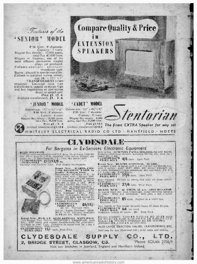
T;4,5 / //; `SEUIJII' MODEL
P.M. Unit : 9" diameter. Capacity : 7 watts.
Magnet flux density : 12.000 gauss, total flux 47,000 lines.
Magnet in Alcomax, one of the most efficient permanent magnet
alloys yet produced. Volume controls: constant -
impedance type. Basins: die -cast in non -ferrous alloy. Cabinet in polished walnut veneer,
size l4s" x í2i? x 7 -. TRANSFORMERS (when
required): Universal ratio type transformers, tapped to match high and low impedances or connection
direct to speech coil. Price £5.15. 6.
(without transformer). £5. 2.6.
JINIOR' MODEL Cabinet size: 131" x I Il" x 6ñ'.
P.M. Unit : 8' diameter. Capacity: 6 watts.
Magnet flux density : 10.000 gauss, total ilus, 39.500 lines.
,/ lform r) . tl. 6
®
(without transformar)£4.tU.6
Compare Quality & Price in
`Ci1llLT.' MODEI. Cabinet size: 121" s 101" x 5;
P.M. Unit: 7" diameter.
/flh//»/ l, Magne[ Huc density: 8,000 gauss, total flux 31,600 lines.
Price £4.10.0 (without transformer) £4.0.0
(.1.14101'l724>
The finest EXTRA Speaker for any set
WHITELEY ELECTRICAL RADIO CO LTD MANSFIELD NOTTS
f'.YIIESIIALE For Bargains in Ex- Services Electronic Equipment
4155 nit 1;11ó:R. Only a few. .lt' \("l'ION P:\NI:L 1011.13338 forche A1134. l aloe Commumieatton and D.F. Revr. (Or 18 -3 mes. 1.5(10 -800 Contains matching sockets. terminal blocks, etc., mad, on a
55.73 mes. In 5 W.B. complete with valves. Circuit and board hin. x 41.n. i, .o,.,, -- 16!- s 9 " ins. less power pack. l'I 51)1:SDAI.I:'S 4/6 c; s ^ I2 /12/O , Pit ICE ONE%
,.-11,1. i Tail, on request.- ('O1t-
l' ".. ii t rancit l'NITS by s., i at inn Corp.
-BC-433 -A or C. 15 rccr. Covers Med.
and Long Wave 150 -1.500 metres in 3 switched. Bands ia, metal case lin. x 21in. x 12in. Plus BC -434.A ('nntrol Box, with " $ " Meter. in metal case.7?ln. x 4ín. x 7 Pian Flexible Tuning
Phts indicator- _1 -81 -A. Phis ator 1 -82 -A. Pliis 5. .. truçtion Bdok eón- rtt data, and circuit fur cr ?6E -A (or C) Radio C !'.q utpment.
( i'i its ONi ' b 15 %- per set. Carriage Paid.
Set of.' Radio Compass' (SCR - 269-A or Cl Circuits available at 2 8 per set. ,Post Paid.
Brand New. Ex-R.A.F. A1134 ItATII :RI' AMPLIFIER. Two Stages. Two Valves, VR21(PM2RL) VR35(QP2211). with Mic., QPP input and output transformers, for inter.còm., pre -amp. or mod. Unit. Complete in metal case 7111., 5in. x 41ín. finish black. With Circuit. - l'LylIF.SDALI. '.S I5 /- oath ,Post Paid. Pli íC1; ONLY
l'o i Paid.
Brand New. BEACON Iti f f15 I I :. It(' -12O6. A midget S'het, in metal Las, ;' x -4 s. 4: ins.. for 200-1, with IS valves: OSAI. 65F'7, 6SK7, óK7.- metal.' 2 25Lí ß,
24 ,volts, miniature 3 gang condenser dial and knob. V I.F. trans., etc., finish black. . -
IL1.1 DESDAI *'S 37/6 oath. Post Paid. PRICE ONLY New- Unused. BC -1206 as above, but with all glass cal finish grey. ('LYDISl).V.I.'r; 27/6 each. 'Post Paid. PIMA.: ONLY
i
BRAND Mill'. 12 1,111.TS 75 n.h. A('(' U1u'LATOt;. In waxed Teak box with hingedjjd. metal tarrying hands, at sides. Wing nut terminals. Size ,16ín. x lin. x 1111u. high... -..
('1.1'Dó:S. \ D1 . 1.' ES PRICE ES O\í..1 each. Packed in a wood box. Carriage P::
Any length ot.t Grade Co -axial Cable 52 ohms 12. mm. CI DESDA1.1's 6d. per yard. PRICE ON1.1 Minimum length 20 yards.. 10.- Post Paid.
Circuits available: T.1154 2:3. 11.1155 1'3, B.C. 348 1 3. RI111 2'3. M.C.R.1 2'9, R.1124, R.1125 and P.U. 1 -9, R.1224 1 3. I.F.F. (U.S.A.) 1i9, SCR -274 -N (Command Bev 4.'8, SCR -289 -A (Compass) 2'8, A.1134 -1'3, all post paid.
ALSO LARGE SELECTION VALVES, TRANSFORMERS, ETC.
Send now for new illustrated lists ; print name and address.
CLYDESDALE SUPPLY CO., LTD, 2, BRIDGE STREET, GLASGOW, CS. . 'Phone SOUth 270óg9 -
Visit our branches in Scotland, England and Northern Ireland
www.americanradiohistory.com