erdc tn doer-t7 (2004). “mechanical dewatering of ... · mechanical dewatering of navigation...
TRANSCRIPT

ERDC TN-DOER-T7 October 2004
Mechanical Dewatering of Navigation Sediments:
Equipment, Bench-Scale Testing, and Fact Sheets
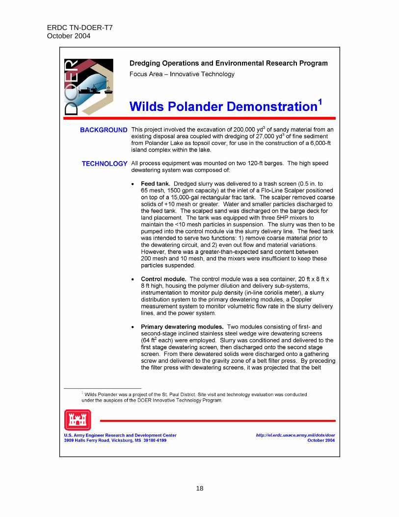
PURPOSE: This technical note provides an overview and technical guidance for evaluating mechanical dewatering at dredged material placement sites. This document introduces the basic pieces of equipment that make up a dewatering circuit or train, some advantages and disadvantages of different equipment options, the state of the practice in bench-scale testing, discussions of performance specifications and cost, and several fact sheets on various process technologies and their applications. BACKGROUND: The fundamental objective of the Innovative Dredging Technology Focus Area of the Dredging Operations and Environmental Research (DOER) Program is to identify and catalog innovative dredging operations, processes, or equipment and techniques developed by domestic and international dredging entities. A number of technologies developed within the U.S. Army Corps of Engineers (USACE) are currently undergoing evaluation for potential demonstration under the DOER Program. Among these is the mechanical dewatering of dredged material at confined disposal facilities (CDFs). INTRODUCTION: The solids content of a typical dredge discharge slurry ranges from roughly 100 to 200 g/l, as compared to the in situ solids content, which may range from 250 to 1800 g/l, depending upon the grain size distribution of the in situ sediment. Conventional upland placement of dredged material involves discharge of the slurry into a CDF, where clarification and settling take place. Clarified water is normally returned to the originating water body. Large areas are required for upland placement of hydraulically dredged sediments, and CDFs must be in relatively close proximity to the shore in order to economically manage return flows. Over time, the material placed in the CDF continues to dewater and consolidate, making room for additional “lifts” from subsequent dredging cycles. Surface trenching and weir management are typically the only active dewatering efforts that take place. Mechanical dewatering uses special equipment to reduce the water content of the dredge slurry at the time of placement. There are a number of possible motivations for considering mechanical dewatering, including: • Remaining storage capacity in the CDF is insufficient for clarification and water
management.
• Sediments are very contaminated and must be transported to a permitted landfill for disposal.
• Conditioning of the material is needed to facilitate handling and transport and to reduce transport costs.
• Water content must be reduced to meet disposal or beneficial use specifications.

ERDC TN-DOER-T7 October 2004
2
Mechanical dewatering is not presently used as a standard operating procedure in dredged material management. However, as the available capacity in existing CDFs has diminished, there has been greater interest in beneficial use of dredged material to reclaim or preserve disposal area capacity. Given the time required for materials to consolidate sufficiently so that they can be excavated and recovered from a CDF, mechanical dewatering may offer a viable means of continuing to operate in a CDF that is nearing the end of its design life. It is envisioned that with proper management these facilities would become “rehandling” stations, and dredged material would be treated as a resource rather than a long-term storage problem. Where sediments are too contaminated for either beneficial use or CDF disposal, savings in transportation costs to a permitted disposal facility may justify the dewatering processing cost. Whatever the motivation, mechanical dewatering is being considered more frequently in dredged material management evaluations. TREATMENT TRAINS: There is a variety of equipment from which to choose in developing a dewatering treatment train. Equipment selection will be based on such variables as sediment characteristics (e.g. grain size distribution, organic content, plasticity), available staging area, capacity requirements, and ultimate disposition of the dewatered dredged material. Available transportation, disposal, and beneficial use alternatives will determine the specifications for the dewatered cake and the importance of volume and weight reduction. A typical treatment train will incorporate the following three primary stages: 1) sand and oversize removal, 2) thickening, and 3) dewatering. Each of these stages may require one or more different pieces of equipment, depending upon the specific requirements of the application and the characteristics of the sediment. Sand and Oversize Removal. Removal of sand, trash, and oversize materials is typically the first operation in a dewatering circuit, as for any physical separation treatment train. Physical separation and dewatering treatment trains may, in fact, be almost identical, with the only difference being the principal processing objective. Sand may be removed first, using a sand screw with sump and conveyor, followed by light trash removal (bark, grass, and plastic) on a scalping screen. Alternatively, oversize materials (e.g. coarse gravel, rocks, debris, and light trash) may be removed first on a grizzly or a vibrating wet screen, followed by sand removal downstream using a hydrocyclone. Advantages of the first approach are: • The sump on the sand screw provides some surge capacity, which is important in coupling
the dewatering treatment train to a dredging process.
• The sand is separated at a point in the system where this will occur without additional energy input, and where energy would otherwise be required to prevent its settling during process stoppages.
• The overflow passes from the sump of the sand screw with sufficient energy to be passed onto the scalping screen for removal of light, floatable trash, and collection of the fine slurry in a mixing tank. Conversely, when the trash and oversize material are separated first on a wet screen, the underflow (sand and fines slurry) must be pumped to the next stage. The presence of coarse organics in the sand, however, may necessitate the use of a hydrocyclone to achieve effective removal of the organics. Also, the fine slurry leaving the mixing tank

ERDC TN-DOER-T7 October 2004
3
must also be pumped to the next stage, so a pump will either precede or follow the sand separation unit operation. Although the bulk of the water reports with the fines, the solids flow rate will be lower for a pump to transfer the fine slurry from the mixing tank to the thickener, than for a pump to transfer the wet screen underflow (sand and fines) to the hydrocyclone. Pump abrasion will also be decreased with removal of the sand.
• The sand coming off the screw is essentially self stacking, and can be periodically removed with a front-end loader. Additional dewatering might be required for the underflow from a hydrocyclone (sand fraction), and a sand screw might be used for this purpose, as well as to convey material from beneath the hydrocyclone. The sand screw followed by the scalping screen therefore requires less equipment overall when additional washing of the sand is not required to remove coarse organics and agglomerated fines.
Thickening. Fine-grain slurries normally require the addition of polymer to coagulate the solids and facilitate dewatering. Polymer may be added to the slurry in a tank and agitated to encourage flocculation, but it is often added in-line, between the sand separation unit and the dewatering stage. At this point, a thickener may be used to settle solids to optimum solids content for the dewatering equipment. The thickener also acts as a clarifier, recovering the free water from this initial dewatering step, and reducing the suspended solids in filtrate returned from the dewatering equipment. The clarifier overflow may be recycled through the system for necessary process dilutions, or returned to the receiving water body. Alternatively, thickening and initial dewatering of fines can be done with an inclined wedge wire screen. However, the inclined screen is sensitive to changes in grain size of the feed, resulting in process upsets and variability in the solids content of materials leaving the screen. Sandy materials may fall through the screen entirely, rather than flowing down the face of the screen to the next stage. Dewatering. Once sand and oversize materials have been removed, and the material thickened if necessary, the fine slurry can be dewatered using a centrifuge or filter press, each of which are available in a variety of configurations. Selection of the best equipment and configuration for the application will depend upon the degree of water removal and volume reduction required, the ability of the equipment to handle the type and volume of material being processed, and the rate of production. Bench and pilot scale testing are typically used to make this determination and to size the equipment. Depending upon the dewatering equipment used downstream of the thickener, additional polymer may be required to further coagulate the solids for the final dewatering step. Insufficiently coagulated or low-solids-content slurry may result in poor solids capture in the dewatering step. Overtreating with polymer can be equally undesirable with respect to processing cost and wastewater quality. DEWATERING EQUIPMENT: Sand Screw. A sand screw typically consists of a sump equipped with a flat or angled auger to transport settled sand from the sump, and a conveyer to feed the sand from the auger (Figure 1). Alternatively, sand may simply be allowed to stack at the base of the sand screw and be handled with conventional earth-moving equipment. Slurry is fed into the top of the sump, and the coarse materials settle onto the auger. Fine and organic materials are carried out in the overflow. The sump may be equipped with counter-current flow capability, to improve the removal of the fines and organics from the sand fraction. The sand fraction can be coarsened by increasing the

ERDC TN-DOER-T7 October 2004
4
throughput, causing the fine sand to report with the fines. This will improve the permeability of the cake produced in the follow-on dewatering processes, but may also decrease compressibility. The sump on the sand screw provides some surge capacity for the system and takes advantage of the fact that coarse materials are difficult to maintain in suspension, even with high-energy mixing. The relative efficiency of fines removal for different materials and varying operating conditions is an area that requires further study for environmental applications. Scalping Screen. A scalping screen removes oversize materials, such as rocks, gravel, bark, plastic, grass, shells, and other debris. Besides being destructive to equipment and filter fabrics, debris constitutes unnecessary treatment and storage volume when carried through the process. A scalping screen may be fixed or rotate in a belt configuration (Figure 2). The belt configuration permits additional capacity in a smaller footprint, and prevents the blinding of the screen with grass and similar materials because they are dropped off the end of the belt as it rotates.
Figure 1. Sand screw
Figure 2. Scalping screen Hydrocyclones. A hydrocyclone is a cone-shaped piece of equipment with no moving parts, constructed of metal or plastic (Figure 3). Hydrocyclones may be lined for improved wear resistance. Slurry is fed into the hydrocyclone tangentially, and flows in a spiral direction down the cone. Finer and lighter materials migrate toward the center of the cone (vortex) and are carried out in the overflow. Coarser and heavier materials leave the cyclone through the apex, as the underflow. The bulk of the water reports with the fines, and the underflow may be relatively well dewatered if the material is coarse (sandy). Hydrocyclones are often used to recover sand, but may be sized for finer separations as well. There may be several advantages to removing sand in a dewatering circuit:

ERDC TN-DOER-T7 October 2004
5
• Materials loading to the presses and equipment abrasion are reduced.
• Polymer costs may be reduced. Dosage of polymers added for the purpose of coagulating fine materials is determined by the solids concentration in the slurry, and is expressed in terms of grams polymer per gram solids. Chemical demand can be reduced by removing the sand, which competes with the fine materials for the polymer.
• Long-term storage capacity requirements may be reduced if alternative uses are available for the sand. Sand removal as a volume reduction measure and beneficial use of dredged materials are topics extensively discussed in a number of other publications (Olin-Estes et al. 2002; Olin-Estes and Palermo 2000a, b; Olin-Estes 2000; Great Lakes Commission 2004a, b).
Figure 3. Hydrocyclone
Figure 4. Wet screen Wet Screen. A wet screen may be used to achieve preliminary size separation of material. Material may be fed onto the screen dry, and washed through the screen by water jets mounted on the top of the screen (Figure 4). The screens are usually mechanically vibrated to facilitate separation. Vibrating wet screens can be useful in breaking up agglomerated clay containing material. Decks are wire or polymer with square or rectangular openings. The openings may blind when presented with grasses or similar debris, thus necessitating the scalping screen.
Surge Tanks/Mixers. One of the principal challenges in incorporating a dewatering circuit as part of a dredging process is the interface between the dredge and the dewatering circuit. Typical dredge sizes used in large-scale maintenance dredging projects are too large to interface well with a dewatering circuit unless significant buffering capacity and system redundancy are incorporated in the dewatering circuit. Because of this, smaller dredges (6- or 8-in. dredges) are typically used. The comparative cost compromise between reduced production at the dredge versus increased capacity of the dewatering circuit, must be balanced in the cost/benefit evaluation.

ERDC TN-DOER-T7 October 2004
6
Clarifiers/Thickeners. High rate, circular clarifiers/thickeners are appropriate for a wide variety of dredged sediment slurries. Typically, suspended solids are increased from 10 to 20 percent dry solids in the influent, to approximately 30 percent solids in the underflow, greatly reducing the slurry volume in the process with this equipment. At the same time, clarified water overflows a weir and is available as process water or is returned to the receiving water body (Figure 5). Polymers are required to accelerate sedimentation and optimize clarified water quality. Features include the ability to process a high volume of solids without fouling, minimum space requirement, rugged construction, and low SS in the overflow (15-30 mg/l). When used to thicken feed for a belt filter press, additional polymers may be added to the underflow, or the solids may need some dilution to meet optimum feed concentrations to the press. Solids can be continuously stirred to maintain pumpability during system shutdown, a significant advantage over lamellar clarifiers. Lamellar, plate-type clarifiers are frequently used for lower concentrations of suspended solids, emphasizing the need for clarification of the overflow water, rather than for the thickening of the underflow. Polymers are required, and the plates are sometimes subject to solids build-up and plugging, especially when applied to heavy concentrations of sticky solids. As a processing alternative, the clarifier may be used as the principal dewatering component. Operated for maximum thickening, a circular clarifier can produce a pumpable underflow of up to 40 percent solids. These partially dewatered materials can then be placed in a containment area for further consolidation. Although a temporary dewatering area would be required, this might be a more cost-effective alternative than mechanical dewatering. Clarifier capacity can be increased at less cost than press capacity, enabling the use of larger dredges for which labor costs are comparable to smaller dredges. Additionally, the dredge can operate more continuously if the capacity of the rate limiting components is increased. This reduces the length of time the dredge must be on-site, resulting in further cost savings.1 Polymer Mixing and Injection Systems. Dry or liquid polymers (nonionic, anionic or cationic) are available for thickening and/or dewatering dredged sediment slurries. To economically justify more capital-intensive dry systems, the polymer requirements must be very substantial because of the solids throughput in the system or because of the large size of the processing system. Small, packaged systems blending neat polymer with water and then 1 Personal communication. May 13, 2004, Vic Buhr, Division Manager of Hydraulic Dredging and Dewatering, J.F. Brennon Co., 820 Bain Bridge, LaCrosse, WI 54602-2557.
Figure 5. Circular clarifier

ERDC TN-DOER-T7 October 2004
7
injecting the diluted polymer through an in-line mixer are economical for smaller systems. However, the cost/pound of liquid polymer is usually higher than for dry polymers. Equipment configuration and high flow rates sometimes dictate the use of flocculant mixing tanks in lieu of in-line mixers. Polymers may be introduced at several points within the treatment train, preceding the thickener for example, and again preceding the principal dewatering equipment. Polymer dosage prior to a belt filter press may be as much as three times higher than the dosage preceding the thickener, which is one of the reasons slurry is not generally fed directly to the press (slurry volume is reduced at the thickener, thus reducing polymer consumption). Various means of controlling the injection rate of mixed or blended polymer into the slurry are commercially available. The degree of automation that is desired depends on a number of factors, including the variability of the feed solids characteristics during the dredging process and/or the change in the percent solids in the slurry. Because many factors affect the amount of polymer that is required and because conditions can change so quickly, automatically adjusted injection can sometimes be difficult to justify from a capital cost perspective. Slurry Density Instrumentation. To achieve optimal system performance, including maximum dewatering effectiveness and minimum polymer consumption, the percent solids in the slurry feeding the dewatering equipment should be continuously monitored and adjusted to a preset level. This is frequently accomplished with a densometer and dilution water from the thickener/clarifier overflow. A controlled proportional valve can be used to introduce the required water flow into the clarifier/thickener underflow. Belt Filter Presses. Belt filter presses have historically been used in the paper industry and for dewatering of sewage sludge, and are well-proven for dewatering dredged material. They offer continuous operation, low operator labor, reasonable capital cost, ease and simplicity of maintenance, high solids throughput, moderate footprint, high solids capture rate (i.e., low solids in filtrate), low power consumption, reasonable polymer consumption rate, high reliability and availability, and adaptability to changing process conditions. However, solids content of the cake may be lower than that produced by a plate and frame press. Typically, a belt filter press will produce a cake of approximately 40 to 50 percent solids by weight, as compared to 50 to 65 percent solids achievable with plate and frame presses. These values are a function of the density of the solids in the material as well as the dryness and compression achieved by the equipment. Solids content for very low-density materials may be more in the range of 30-40 percent solids. Solids content may be a pivotal factor where the final weight or volume of the processed material factors significantly into management economics, as it does when transport or off-site disposal costs must be considered. A belt press has three dewatering zones: gravity, wedge, and high pressure. Free water drains from the conditioned sludge in the gravity zone. The press is equipped with rakes to distribute the material and encourage drainage (Figure 6). In the wedge zone, the sludge is captured between two moving belts where additional water is squeezed out under low pressure as the belts converge. The belts sandwich the now more-compressed sludge and pass over a series of rollers of decreasing size and increasing pressure to further reduce the water content (Figure 7). The number of rollers employed can be varied according to product specifications and requirements of the material being processed.

ERDC TN-DOER-T7 October 2004
8
Figure 6. Belt filter press rakes in gravity drainage zone
Figure 7. Belt filter press
If the conditioned sludge is insufficiently flocculated, an excessive amount of solids may be lost through the belt. In other cases, a well-flocculated sludge will fail to drain properly in the gravity zone. When the sludge enters the low-pressure zone, it may then migrate off the edge of the belts (i.e. soft migration), resulting in low solids capture, high filtrate solids, and a fouled processing area. A similar phenomenon occurs with cake that is insufficiently dewatered upon reaching the high-pressure zones, and is termed “hard migration” (Neogen Corporation 1992). If the cake becomes extruded into the belt, it may fail to release. A dirty belt subsequently leads to failure in the gravity zone, further compounding the problem that was initiated due to inadequate gravity drainage. Plate and Frame Presses. Also known as recessed chamber filter presses, these machines process slurry in batches, although multiple compartments or parallel installations may be employed to achieve continuous operation (Figure 8). Slurry is fed into each compartment (frame) of the press, where the solids are retained on a membrane and the water passes through as filtrate. Flow is stopped at a specified pressure differential, the filter plates are opened, and dewatered cake is discharged. In order to avoid interruptions to the dredging operation, adequate storage or surge capacity must be available upstream of the press, with sufficient system redundancy to permit continuous operation. This type of operation may have higher operator labor requirements, a larger footprint, and a higher capital cost than the belt filter press. However, the solids capture rate is very high, as is the percent solids in the filter cake. Savings in trucking or offsite disposal costs for the dryer, more condensed cake may justify the differences in capital and operating costs relative to belt filter presses. This should be evaluated in the cost/benefit analysis. As for all dewatering processes, polymer cost varies with the physical characteristics of the solids. Power cost can be high as a result of a high pressure drop as the filter becomes loaded with solids. Fixed volume filters require a specific volume of solids in order to produce the driest possible cake. Addition of a diaphragm or membrane plate produces a variable volume filter. The bladder or diaphragm may be inflated to physically press additional liquid from the filter cake, reducing cycle time and producing dryer cakes when solids capture is low relative to the filter capacity

ERDC TN-DOER-T7 October 2004
9
Figure 8. Plate and frame press (photograph provided courtesy of U.S. Filter Dewatering Systems, Holland, MI)
(U.S. Filter 2004). Pumping costs associated with high pressure differentials necessary to fill the filter to capacity may also be reduced with the use of a bladder press. Centrifuges. Centrifuges operate continuously, and they feature low operator labor costs. Capital cost varies, depending on the design and resulting dewatering effectiveness of the machine. As for the other dewatering equipment, polymer consumption varies with solids characteristics. Power requirements are high and abrasion on internal parts can be problematic. Maintenance is very sophisticated; reliability and availability can be problematic on abrasive materials. The solids capture rate tends to be lower (resulting in more solids in the centrate) than for either belt or plate and frame presses, but centrifuges can be very effective for some materials (Figure 9). Centrifuges are very compact and can be accommodated in a relatively small footprint (Figure 10). BENCH AND PILOT SCALE TESTING: Full-scale operations should be preceded by adequate material characterization, and appropriate bench- and pilot-scale testing. Bench-scale testing is employed to identify suitable polymers and dosages, and evaluate the expected processing requirements of the material to meet project objectives. Initial equipment selection should be based on bench-scale testing. This is followed by pilot-scale testing to ascertain process response to the variability of the material that can be expected on a larger scale. Pilot-scale testing allows adjustments to be made to the equipment or process at a point where cost impacts would be less than would be incurred after full-scale processing begins. Information obtained from bench- and pilot-scale testing may also be valuable in developing performance specifications.

ERDC TN-DOER-T7 October 2004
10
Figure 9. Flocculated slurry, supernatant and cake (Photo provided courtesy Centrisys)
Figure 10. Decanting centrifuge (Photo provided courtesy Centrisys)
Physical and chemical characterization of the in situ material should include grain size distribution, water content, percent solids, bulk specific gravity and specific gravity of the solids, organic content, Atterburg limits, and chemical analysis of expected processing streams. If contaminant concentrations are of concern, and size separations are to be done prior to the principal dewatering step, chemical concentrations should be measured in the resulting solid and aqueous process streams. Estimates of filtrate suspended solids and total and dissolved contaminants will typically be of interest. Control of volatile emissions may also be a permit requirement. Process flow diagrams with material mass balances will normally be needed. Polymer Testing. Conditioners (flocculants) are used to produce optimum slurry suspended solids in the feed to the dewatering equipment. Equipment performance is dependent upon selection of an appropriate conditioner. The floc must have enough shear strength to minimize solids losses in the dewatering equipment, but must be permeable enough to permit free drainage. Chemical conditioners often constitute a major operating cost of a dewatering circuit, so this step is very important with respect to process economics. Typically multiple conditioners will be evaluated at bench scale to identify those that produce the best sludge for the least cost. The best conditioners identified in bench tests will then be evaluated with the bench- and pilot-scale dewatering equipment. Bench-scale testing may consist of a fairly simple funnel and filter apparatus to evaluate gravity drainage characteristics of the flocculated material. It is common to test a large number of polymers in order to identify the optimum conditioner and dosage. Toxicity of conditioners may become an issue if filtrate and process water are to be discharged to a water body without further treatment. Crown Press. The Crown PressTM is a bench-scale piece of equipment intended to model the belt filter press (Figure 11). The press facilitates evaluation of conditioners and belt materials, and the action of multiple rollers can be simulated to achieve a specific cake dryness and density. Migration of sludge on the belt can be measured. The belt tension applied on the bench press translates to the units of force per inch. This information is used in adjusting the belts on a full-scale press. Process variables of interest are: solids throughput rate, filtrate quality and

ERDC TN-DOER-T7 October 2004
11
suspended solids, cake dryness or density, and polymer requirements. The bench press facilitates the correlation between performance of the compression zones of the press and changes in one or more of these variables. A gravity test drainage kit is also included to simulate drainage of the sludge in the gravity zone of the belt press (Figure 12). The actual sludge sample volume required for testing must be calculated, but typically ranges from 100 ml to 400 ml. More complete information regarding the equipment and recommended testing procedures can be found in the Crown PressTM Owners Manual (Neogen Corporation 1992), which is also available on-line, and in Severin et al. (1998).
Figure 11. Crown PressTM
Figure 12. Crown PressTM gravity test kit Chamber Filter Press. This bench-top unit models the plate and frame press (Figure 13). Approximately 1 L of slurry is fed into the top of the unit and is compressed to about the size of a hockey puck. The properties of the compressed cake can be measured and utilized in scaling up the process. Testing units like this are made by a number of manufacturers. The unit pictured is made by U.S. Filter.1 Plate and Frame Press. This unit is a lab-scale version of the full-scale plate and frame press. The unit may be equipped with single or multiple chambers, with a filter volume ranging from approximately 1.0 ft3 to 2.6 ft3, and maximum
1 Personal communication. March 24, 2004, Robert Hamm, Lab Director/Process Development Mgr. U.S. Filter/JWI Inc., Holland, MI 49414.
Figure 13. Chamber filter press

ERDC TN-DOER-T7 October 2004
12
operating pressures of 225 psig (Figure 14). Specifications will vary with manufacturer. Presses may be equipped for counter-current operation to facilitate cake washing. Presses may be trailer-mounted for mobility (Figure 15). A press with multiple leaves is typically quite heavy (up to 1,500 lb).
Figure 14. Single frame plate and frame press
Figure 15. Trailer-mounted plate and frame press Estimating Volume Reduction. A simple method of estimating the volume reduction that can be achieved based on bench-scale testing requires measurement of the initial and final water content, sand removal efficiency (if applicable), mass sand and fines in the in situ or unseparated sediment, and the initial and final total density. From these parameters, a bulking factor can be calculated (which would be less than one for dewatering). The relationship is as follows (Olin-Estes et al. 2002):
( ) ( )
( )( )1 1-
1
f m S F ti i i
i S F ti i f
w x M M
w M Mb
+ + ρ
+ + ρ
⎡ ⎤⎣ ⎦= (1)
where:
wi and wf = initial or in situ and final water content, as a decimal
xm = sand removal efficiency by mass, as a decimal
MSi = mass sand, initial
MFi = mass fines, initial
ρti = total or wet density, initial or in situ
ρtf = total or wet density, final
The relative initial and final material volumes are then given by:
f iT TV bV= (2)
PERFORMANCE SPECIFICATIONS: Developing suitable performance specifications is critical to the success of a dewatering project. There is a balance that must be achieved in order to take into account project goals, the variability of the material being processed, and the impact of processing variations on operating and disposal costs. Performance specifications must take

ERDC TN-DOER-T7 October 2004
13
into account the risk tolerance of all parties in order to achieve project goals and minimize costs as well as establishing the basis for contract payment. Performance Goals and Objectives. Processing goals and objectives must be clearly articulated and the manner in which performance will be evaluated explicitly specified. A careful cost/benefit analysis will help to identify the chief operating objectives. For example, in cases where volume and weight of material must be minimized in order to reduce transportation and offsite disposal costs, the performance specification might be based on a minimum cake density and maximum water content that would be acceptable. However, a processing cost incurred to achieve a tight specification may offset the potential savings in transportation and disposal costs. A slightly less efficient and less expensive treatment train might yield the lowest overall project costs. Risk Tolerance. Performance specifications written with a tight material specification increase the risk to the contractor, who must base his ability to process a heterogeneous material to specifications on limited bench and pilot testing. Higher risk generally results in higher contract bids. Conversely, a contract specifying only the processing method, which might be considered desirable based on results of preliminary bench scale testing, would be easier for the contractor to estimate, but may not sufficiently motivate the contractor to operate in a manner that optimizes material properties or results in the least cost for the sponsor. Processing interruptions in the dewatering circuit may impact the dredging operation. Because both dredging and dewatering are relatively specialized functions, however, contracts may be let to separate companies who may then find themselves in an adversarial position. The dewatering plant must have adequate capacity to minimize disruptions to the dredging. Similarly, the dredge must be operated in a manner that provides the greatest possible uniformity in the influent to the dewatering circuit. Highly variable slurry solids or flow rates may result in processing upsets and down time on both ends. Instrumentation linking the dredging plant and the dewatering circuit can minimize problems and reduce overall costs due to greater operating efficiency. This approach has been demonstrated in the field and is described in the Clinton, Iowa, fact sheet in Appendix A. Material Properties. Performance specifications based upon material properties must consider the possibility of material variability on both sides of the treatment train and specify remedies and responsibilities arising from that. Off-spec materials may result from processing operations that are not sufficiently robust or from poor process design. However, off-spec materials may also result from unanticipated variability in the feed. If the material obtained for bench-scale testing and process design is not representative of the full range of materials to be processed, substantial additional costs may be incurred in order to make necessary modifications to the process. Plant design is based on the measurable properties of representative samples, taking into account an appropriate level of variability and uncertainty. This could be taken to constitute a feed “spec.” The processing modifications required to handle feed outside these parameters should be anticipated, however, and costed along with the mainstream processing activities. For example, if sand content was less than 2 percent in the pre-design sampling, and no sand removal

ERDC TN-DOER-T7 October 2004
14
operations were included in the plant design, what are the impacts if 25-percent sand is encountered? What costs would be anticipated in connection with this, including equipment changes and dredging or processing interruptions? These are the uncertainties that drive costs of remediation activities up. Defining the necessary actions and remedies in advance, to the extent possible, allows better definition of the risk to all parties. It is to be hoped that this will have the ultimate effect of reducing the cost of processing for mainstream materials treatment. Sampling and testing to determine compliance with materials specifications should also be carefully developed. The scale of material heterogeneity should be considered. Sampling volume, location, frequency, and sampling and analytical methods must be explicitly specified. Uncertainty associated with the sampling and analysis should be estimated and factored into considerations. Material variations resulting from changes in operating conditions should also be considered in specifying performance testing. For example, percent solids of the cake is a commonly tested parameter for process comparison. However, percent solids in the cake is a function of the compaction and dryness of the materials (% solids = mass solids/total mass), and the specific gravity of the materials in the sample tested. Percent solids may be increased in organic sediment by coarsening the cut at the front of the treatment train and allowing more sand to report with the fines. The density of the cake would be higher, and permeability may be improved, but the volume may also increase due to the higher mass reporting with the fines and decreased material compressibility. Higher percent solids for materials of the same specific gravity would indicate greater volume reduction. Testing of the cake should therefore also include not only percent solids, but bulk density of the cake, specific gravity of the solids, grain size distribution, and water content in order to fully determine the fate of materials and the effectiveness of the process. Use of these factors in evaluating overall volume reduction was discussed earlier in this document. Weight reduction can be estimated using the same parameters. Basis of Payment. Payment is typically specified in terms of cost per unit volume dredged. Alternatively, payment might be specified in terms of cost per unit volume processed, or cost per unit volume cake produced. The obvious disadvantage of the latter specification is that the contractor will profit from maximizing the cake volume, which will likely be contradictory to processing and cost reduction objectives. Chemical costs, however, should be correlated and charged based on the volume or mass of fines processed, rather than the total volume of sediment processed. For example, if sand content is higher than expected, chemical demand will be lower. Chemical costs based on total sediment volume would not reflect this. Process water normally requires treatment prior to discharge. If the dewatering contractor is responsible for water treatment costs, this may motivate conservative water use and minimize the volume of water to be treated. Emissions control, decontamination, and other site management considerations will normally be encompassed in the agreement as well. Payment basis is therefore an area which should be given careful consideration when developing performance specifications. COST: Unit treatment costs are a function of character and volume of the material to be processed. Mobilization and demobilization costs are relatively insensitive to treatment volume; small projects will therefore have a higher associated unit cost. Mechanical dewatering is

ERDC TN-DOER-T7 October 2004
15
dependent upon chemical addition to flocculate the material. Under unfavorable conditions (in which the slurry requires high dosages of flocculants) chemical costs can outweigh equipment costs. The fact sheets in Appendix A give a range of costs for the processes described, reflecting the impact of less-than-optimum operating conditions. When comparing cost estimates from different vendors, care should be taken to do so on an equivalent-cost basis. If one estimate includes wastewater treatment and another does not, for example, it may be impossible to extract these cost differentials and establish a uniform basis for comparison. Requests for proposals should attempt to address this issue by specifying all cost items that are to be included or itemized. APPLICATION TO USACE DREDGING PROJECTS: With decreasing storage capacity available, managers in many areas of the country are considering efforts to recover and put to beneficial use previously dredged materials. Often transport and placement specifications require that the material be dewatered. While this can be effectively accomplished with passive dewatering methods, area requirements are large and time to achieve sufficient dewatering for the materials to be workable may be lengthy. Additionally, construction costs for new CDFs are high. Dewatering technology has matured in recent years, making material processing more cost-competitive than in the past. Where existing upland storage is available and adequate, mechanical dewatering will typically not be the least-cost alternative. Where storage is limited or must be constructed, or where offsite disposal options are being considered, mechanical dewatering may offer a reasonable alternative for some projects. ACKNOWLEDGEMENTS: The contributions of the co-authors of this document, and the companies with which they are affiliated, are gratefully acknowledged: John Waugh, Phoenix Process Equipment Company, Louisville, KY; Robert L. Schwartz, Solomon Technologies and Operations Services Corporation (while contributing to this article, now employed by Hazen Research, Golden, CO); Glen Green and Vic Buhr, J. F. Brennan Company, LaCrosse, WI ; Bob Braddock, Solomon Technologies and Operations Services Corporation, Lakewood, CO; Heinz-Dieter Detzner, Department of Port and River Engineering, State Ministry for Economic and Labour Affairs, Hamburg, Germany. POINTS OF CONTACT: For additional information contact Ms. Trudy Estes (601-634-2125, [email protected]), or the manager of the Dredging Operations and Environmental Research Program, Dr. Robert M. Engler (601-634-6324, Robert.M. [email protected]). This technical note should be cited as follows:
Estes, T. J., Waugh, J., Schwartz, R. L., Green, G., Buhr, V., Braddock, B., and Detzner, H.-D. (2004). “Mechanical dewatering of navigation sediments: Equipment, bench-scale testing, and fact sheets,” DOER Technical Notes Collection (ERDC TN DOER-T7), U.S. Army Engineer Research and Development Center, Vicksburg, MS. http://el.erdc.usace.army.mil/dots/doer/doer.html

ERDC TN-DOER-T7 October 2004
16
REFERENCES: Centrisys. (2004). www.centrifuge-systems.com
Detzner, D., Kitschen, L., and Weimerskirch, W. (1993). “METHA – The first large-scale plant for treatment of harbour sediments,” Aufbereitungs-Technik 34: 235-242.
Great Lakes Commission (2004a). “Testing and evaluating dredged material for upland beneficial uses: A regional framework for the Great Lakes,” Ann Arbor, MI. www.glc.org/dredging/publications
Great Lakes Commission. (2004b). “Upland beneficial use of dredged material testing and evaluation annotated bibliography,” a companion to “Testing and Evaluating Dredged Material for Upland Beneficial Uses: A Regional Framework for the Great Lakes,” Ann Arbor, MI. www.glc.org/dredging/publications
JCI/Upcycle Associates, LLC. (2002) “Sediment decontamination and beneficial use pilot project,” Final Summary Report, May 2002, Prepared for New Jersey Department of Transportation, Office of Maritime Resources, and United States Environmental Protection Agency, Region 2, through Brookhaven National Laboratory. www.bnl.gov/wrdadcon/publications/reports/report.htm
Neogen Corporation. (1992). “Crown PressTM Owners Manual,” Lansing, MI. www.phippsbird.com/pdf/CrownPressManual.pdf
Netzband, A., Hakstege, A. L., and Hamer, K. (2002). “Dutch-German exchange on dredged material - Part 2 - Treatment and Confined Disposal of Dredged Material September 2002,” Coordinated by: A. Netzband / Strom- und Hafenbau, Hamburg, A.L. Hakstege / AKWA/WAU, Utrecht, K. Hamer / Universität Bremen.
Olin-Estes, T. J. (2000). “Determining recovery potential of dredged material for beneficial use – Site characterization: Statistical approach,” DOER Technical Notes Collection (ERDC TN-DOER-C15), U.S. Army Engineer Research and Development Center, Vicksburg, MS. http://el.erdc.usace.army.mil/dots/doer/doer.html
Olin-Estes, T. J., and Palermo, M. R. (2000a). “Determining recovery potential of dredged material for beneficial use – Soil separation concepts,” DOER Technical Notes Collection (ERDC TN-DOER-C13), U.S. Army Engineer Research and Development Center, Vicksburg, MS. http://el.erdc.usace.army.mil/dots/doer/doer.html
Olin-Estes, T. J., and Palermo, M. R. (2000b). “Determining recovery potential of dredged material for beneficial use – Site characterization: Prescriptive approach,” DOER Technical Notes Collection (ERDC TN-DOER-C14), U.S. Army Engineer Research and Development Center, Vicksburg, MS. http://el.erdc.usace.army.mil/ dots/doer/doer.html
Olin-Estes, T. J., Bailey, S. E. , Heisey, S.A., and Hofseth, K. D. (2002). .Planning level cost-benefit analysis for physical separation at confined disposal facilities,. DOER Technical Notes Collection (ERDC TN-DOER-C27), U.S. Army Engineer Research and Development Center, Vicksburg, MS. http://el.erdc.usace.army.mil/ dots/doer/doer.html
Severin, B. F., Prindle, G., and Traynor, G. (1998). “Belt press dewatering: Laboratory simulation of the pressure rollers,” Environmental Technology 19, 697-708.
U.S. Filter. (2004). www.usfilter.com
NOTE: The contents of this technical note are not to be used for advertising, publication, or promotional purposes. Citation of trade names does not constitute an official endorsement or approval of the use of such products.

ERDC TN-DOER-T7 October 2004
17
APPENDIX A: INNOVATIVE TECHNOLOGY FACT SHEETS
ERDC TN-DOER-T7 October 2004
18

ERDC TN-DOER-T7 October 2004
19

ERDC TN-DOER-T7 October 2004
20

ERDC TN-DOER-T7 October 2004
21

ERDC TN-DOER-T7 October 2004
22

ERDC TN-DOER-T7 October 2004
23

ERDC TN-DOER-T7 October 2004
24

ERDC TN-DOER-T7 October 2004
25

ERDC TN-DOER-T7 October 2004
26

ERDC TN-DOER-T7 October 2004
27

ERDC TN-DOER-T7 October 2004
28

ERDC TN-DOER-T7 October 2004
29

ERDC TN-DOER-T7 October 2004
30

ERDC TN-DOER-T7 October 2004
31

ERDC TN-DOER-T7 October 2004
32

ERDC TN-DOER-T7 October 2004
33

ERDC TN-DOER-T7 October 2004
34