equipment configuration - kobe steel · equipment configuration the specifications are subject to...
TRANSCRIPT

http://www.sisco.kobelco.com
Sales & Marketing Department2-3-1, Shinhama, Arai-cho, Takasago-City, Hyogo 676-8670, JAPANTel: +81-79-445-7253 Fax: +81-79-445-7156E-mail : [email protected]
Tokyo Office15th floor, ON Bldg., 5-9-12 Kitashinagawa, Shinagawa-ku, Tokyo 141-8688, JAPANTel: +81-3-5739-5346 Fax: +81-3-5739-5348
●Distributor
Read the instruction manual carefully before using the SH-67.CAUTION!
Equipment Configuration
The specifications are subject to change without prior notice.
2018.3
Item
Object to be measured
Measurement range
Measurement resolution
Measurement repeatability
Scanner interface
Sensibility
Adjustable gain
Center frequency and band width
Amplification linearity
Test range
Display time-base linearity
AC adapter
Battery
Battery operating time
Ambient temperature
Display and screen size
External dimensions (mm), Mass (kg)
Depth of the induction hardened layer
0.7 to 15mm
0.1mm
±0.1mm (per one location)
Included (The scanner is optional.)
80 dB or more (5 MHz narrow band)
110 dB with 0.1 dB pitch
0.25/0.5/1/2/3/4/5/10/15/20/25 MHz
±3% or less
1 to 14,556mm (longitudinal mode in steel)
±1% or less
AC100 to 240V±10%, 50/60Hz±3Hz, Power consumption: approx. 20 W
Lithium-ion battery
Approx. 8 hrs (Operating time is subject to the operation condition and ambient temperature.)
0 to 40°C during operation, -20 to 60°C during storage
6.5" TFT color LCD (Super luminosity LED liquid crystal display)
286 (W) × 180 (H) × 110 (D) (not including the projection), 3.5 kg (including a battery)
Body case Waterproof and dustproof standard: Compliance with IP66. Made of reinforced ABS resin (front and back) and aluminum alloy (midsection)
Card slot
ConnectorExternal interface
USB (master/slave)
SD memory card
LAN, VGA. Encoder (two-axis)
DC input (A dedicated AC adapter is used.)
Earphone microphone (JEITA RC-5240)
Ultr
ason
ic te
stin
gfu
nctio
nMe
asur
ing ca
sede
pth
func
tion
Performance
Measuring Equipment of the Hardened Layer Depth
SH-67Nondestructive measurement of induction hardened layer depth
Standard Components
SH-67: 1
Probe: 1
Probe holder: 1 (designed and manufactured for each work)
Probe cable and other attachments: 1 set
Battery: 1
AC adapter: 1
SD memory card: 1
Specifications
SD memory card
Personal computerLAN
One axis scannerProbe holder
Probe
Standard Components
Options
Co
mm
on
sp
ecif
icat
ion
s
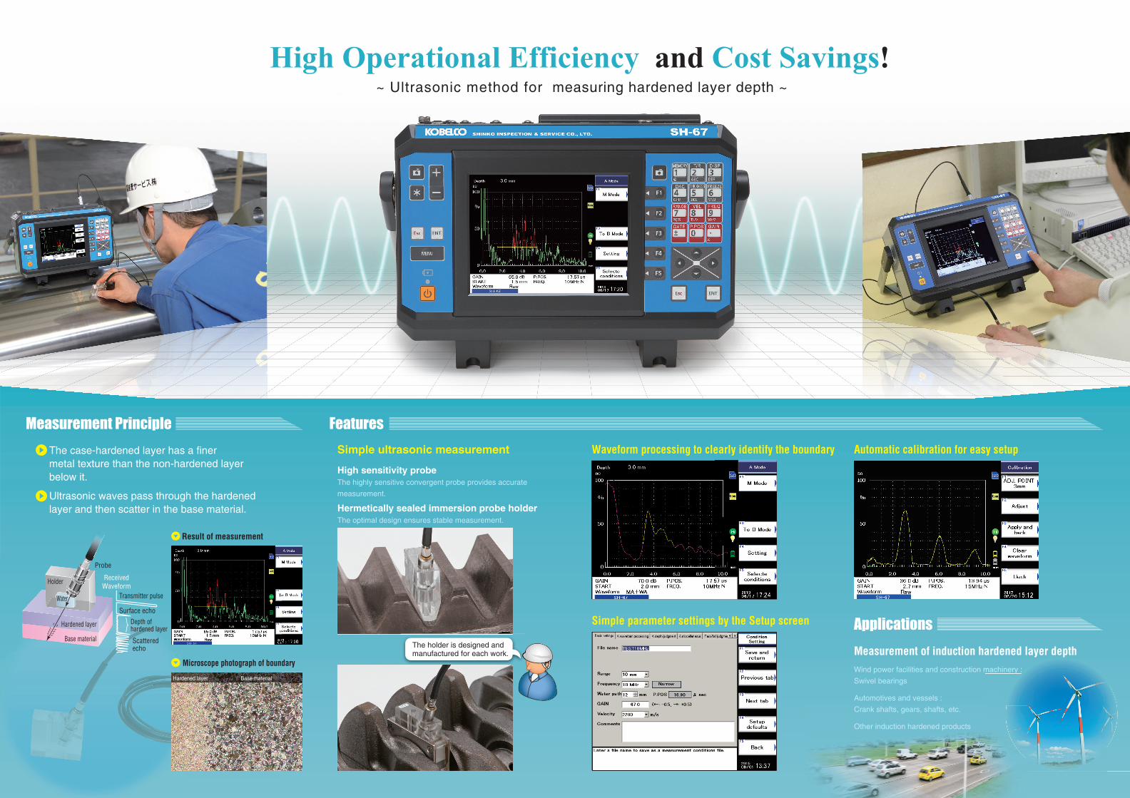
High Operational Efficiency and Cost Savings!~ Ultrasonic method for measuring hardened layer depth ~
Measurement Principle Features
Applications
Probe
Transmitter pulse
Surface echo
Depth of hardened layer
Scattered echo
Holder ReceivedWaveform
Hardened layer
Base material
Simple ultrasonic measurement Waveform processing to clearly identify the boundary Automatic calibration for easy setup
Simple parameter settings by the Setup screen
Measurement of induction hardened layer depthWind power facilities and construction machinery :
Swivel bearings
Automotives and vessels :
Crank shafts, gears, shafts, etc.
Other induction hardened products
The case-hardened layer has a finer metal texture than the non-hardened layer below it.
Ultrasonic waves pass through the hardened layer and then scatter in the base material.
Result of measurement
Microscope photograph of boundary
Hardened layer Base material
High sensitivity probeThe highly sensitive convergent probe provides accurate
measurement.
Hermetically sealed immersion probe holderThe optimal design ensures stable measurement.
The holder is designed and manufactured for each work.
Water
machinery :