equilibrium and elasticitymirov/lectures 30-32 chapter... · 2013-03-01 · chapter 12 equilibrium...
TRANSCRIPT

PH 221-1D Spring 2013
EQUILIBRIUM and ELASTICITY
Lectures 30-32
Chapter 12 (Halliday/Resnick/Walker, Fundamentals of Physics 9th edition)
1

Chapter 12Equilibrium and Elasticity
In this chapter we will define equilibrium and find the conditions needed so that an object is at equilibrium.
We will then apply these conditions to a variety of practical engineering problems of static equilibrium.
We will also examine how a “rigid” body can be deformed by an external force. In this section we will introduce the following concepts:
Stress and strain Young’s modulus (in connection with tension and compression) Shear modulus (in connection with shearing) Bulk modulus (in connection to hydraulic stress)
2

We say that an object is in equilibrium when the following two conditions are satisfied:
1. The linear momentum of the center of mass is constant
2. The angular momentum
Equ
ilib
about the cent
rium
P
L
er of mass or any other point is a constant
Our concern in this chapter is with situtations in which 0 and 0That is we are interested in objects that are not moving in any way (this includ
P L
es translational as well as rotational motion) in the reference frame from which we observe them. Such objects are said to be in In chapter 8 we differentiated betw
staticeen st
equiable
lian
briumd unstable static equilibrium
If a body that is in static equilibrium is displaced slightly from this positionthe forces on it may return it to its old position. In this case we say that theequilibrium is . If the body does not return to its old position then the equilibrium is
stableun stable.
3

A simple method for the experimental determination of the center of mass of a body of a complicated shape
A rigid body supported by an upward force acting at a point on the vertical line through its center of mass is in equilibrium
The center of mass is at the intersection of the new and old prolongations of the string.
Stable, unstable and neutral equilibriumA body suspended from a point above its center of mass is in stable equilibrium
2) The force of gravity and supporting force produce a torque that tends to return the body to the equilibrium position.
4

If the body is supported by a force applied at a point below the center of mass it is in unstable equilibrium
A chair supported at a point directly below the center of mass. If we turn the chair slightly the chair tends to topple over.
A body supported at its center of mass is in neutral equlibrium
If we turn such a body, it remains in equilibrium in its new position and exhibits no tendency to return to its original position or to turn farther away.
5

An example of is shown in the figuresIn fig.a we balance a domino with the domino's center of massvertically above the supporting edge. The torque of the
gra
un
vit
stable equil
ational forc
ibrium
e gF
about the supporting edge is zero
because the line of action of passes through the edge. gF
Thus the domino is in equilibrium. Even a slight force on the domino ends
the equilibrium. As the line of action of moves to one side of the supporting
edge (see fig.b) the torque due to ig
g
F
F
s non-zero and the domino rotates
in the clockwise direction away from its equilibrium position of fig.a.The domino in fig.a is in a position of unstable equilibrium.The domino is fig.c is not quite as unstable. To topple the domino the applied force would have to rotate it through and beyond the position of fig.a. A flick of the finger against the domino can topple it.
6

In chapter 9 we calculated the rate of change for the linear momentum of the center
of mass of an object. If
The Condi
an objec
tions of equilibri
t is in translational equilibrium
u
t n
m
henetdP Fdt
constant and thus 0
In chapter 11 we analyzed rotational motion and saw that Newton's second law takes the
form: For an object in rotational equilibrium we hav
0
e:net
netdPPdt
dLdt
F
constant
0
The two requirements for a body to be i
0
n equilibrium are:
net
L
dLdt
1. The vector sum of all the external forces on the body must be zero
2. The vector sum of all the external torques that act on the body measured about any point must be zero
0 netF
0net
7

, , ,
, , ,
In component form the conditions of equilibrium are:Balance of forces: 0 0 0
Balance of torques: 0 0 0
We shall simplify matte
net x net y net z
net x net y net z
F F F
rs by considering only problems in which all the forces that act on the body lie in the xy-plane. This means that the only torques generated by these forces tend to cause rotation about an axis paral
,
,
,
,
lel to the z-axis. With thisassumption the conditions for equilibrium become:Balance of forces:
Balance of torques: Here is the net torque prod
0 0
uced l0
by a
net x net y
net z
net z
F F
l external forces either aboutthe z-axis or about axis parellel to it.
Finally for static equilibrium the linear momentum of the center of mass
must be zer
any
0o:
P
P
, ,
,
0 00
net x net y
net z
F F
8

The gravitational force acting on an extended body is the vector sum of thegravitational forces acting on the individual elements of the body. The
The center
gravitati
of G
onal
f
ravity (c
orce
g)
o
gF
on a body effectively acts at a single point known as the center of gravity
of the body. Here "effect If the individual
gravitational
ively" has the following meaning
forces on the elements of th
:
e body are turned off and replaced by acting at the center of gravity, then the net force and the net torque about any pointon the body does not chang We shall prove that if the acceleration o ge. f ra
gF
center of gravitycenter of mass
vity isthe same for all the elements of the body then the coicides with the . This is a reasonable approximation for objects near the surface of the earth because
g
changes very little.g
9

Consider the extended object of mass shown in fig.a. In fig.awe also show the i-th element of mass . The gravitational forceon is equal to where is the acceleration of gravity in
i
i i i i
Mm
m m g g the vicinity of . The torque on is equal to . The net torque
(eqs.1)
Consider now fig.b in which we have replaced the forces by the
net gravitational force
i i i gi i
net i gi ii i
gi
g
m m F x
F x
F
F
acting at the center of gravity. The net
torque is equal to : (eqs.2)net net cog g cog gii
τ x F x F
If we compare equation 1 with equation 2 we get:
We substitute for and we have:
If we set for all the elements
cog gi gi ii i
i i gi cog i i i i ii i
i ii
i cog comi
i
x F F x
m g F x m g m g x
m x g g x x
m
10

Statics Problem Recipe
1. Draw a force diagram. (Label the axes) 2. Choose a convenient origin O. A good choice is to
have one of the unknown forces acting at O3. Sign of the torque for each force:
- If the force induces clockwise (CW) rotation + If the force induces counter-clockwise (CCW) rotation
4. Equilibrium conditions:
5. Make sure that: numbers of unknowns = number of equations
, ,
,
0 00
net x net y
net z
F F
11

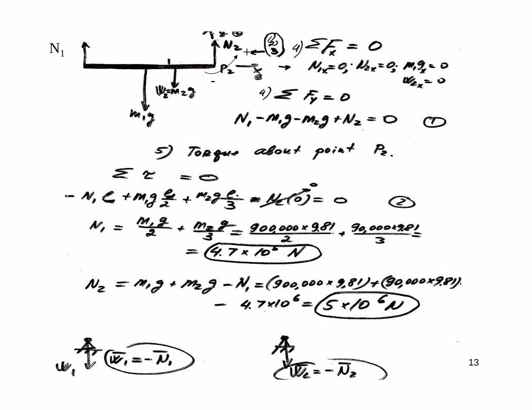
Examples of Static Equilibrium
A locomotive of 90,000 kg is one third of the way across a bridge 90 m long. The bridge consists of a uniform iron girder of 900,000 kg, which rests at two piers. What is the load on each pier?
Method:1. Select the body which is to obey the equilibrium
condition2. List all the external forces that act on this body and
display them on a free body diagram3. Choose coordinate axes and resolve the forces into x
and y components. (+ or – with respect to positive direction that you have chosen)
4. Apply equilibrium condition: ΣFx = 0ΣFy = 0
5. Make a choice of axis rotation. Choose positive direction of rotation. Apply the static equilibrium condition
6. Solve the equations in steps 4 and 5 for the desired unknown quantities.
12
13
-
+N1

A uniform beam of length and mass = 1.8 kg is at rest on two scales.
A uniform block of mass = 2.7 kg is at rest on the beam at a distance /4 f
Sample Prob
rom its lef
lem
t en
d
.
12-
Cal u
1.
c lat
L mM
L
,
e the scales readings0 (eqs.1)
We choose to calculate the torque with repsect to an axis through the left end of the beam (point O).
net y rF F F Mg mg
, 0 (eqs.2)4 2
2.7 9.8 1.8 9.8From equation 2 we get: 15.44 15 N4 2 4 2
We solve quation 1 for = 2.7+1.8 9.8 15.44 28.66 N29 N
net z r
r
r
L LMg mg L F
Mg mgF
F F Mg mg FF
O
14

A ladder of length = 12 m and mass = 45 kg leans against a frictionless wall.The ladder's upper end is at a height = 9.3 m above the pavement on which
Sample
the lower end rests.
Problem 12-2: Lm
h
2 2
The comof the ladder is /3 from the lower end. A firefighter of mass = 72 kg climbs half way up the ladderFind the forces exerted on the ladder by the wall
and the pavement. Distance 7.58
LM
a L h m
,
,
,
We take torques about an axis through point O.
03 2
9.8 7.58 72 / 2 45 / 32 3 407 N 410 N9.3
0 410 N
0 9.8 72 4
net z w
w
net x w px px w
net y py py
a ah F mg Mg
M mgaF
hF F F F F
F F Mg mg F Mg mg
5 1146.6 N 1100 N
15

A safe of mass = 430 kg hangs by a rope from a boom with dimensions = 1.9 m and = 2.5 m. The beam of the boom has mass = 85 kgFind the tension
Sample
in
Problem
the cabl
12-3:
e and the mc
Ma
b mT
,
agnitude of the net force exerted on the beam by the hinge.We calculate the net torque about an axis normal to the page that passes through point O.
02
9.82
net z c r
c
F
ba T b T mg
mgb MT
a
2.5 430 85 / 26100 N
1.9
,
,
2 22 2
0 6093 N
0 9.8 85 430 5047 N
6093 5047 7900 N
net x h c h c
net y v r v r
h v
F F T F T
F F mg T F mg T g m M
F F F
16

O
A 70 kg rock climber hangs by the crimp hold of one hand. Her feet touch the rock directly below her fingers. Assume that the force from the horizontal ledge
S
s
ample Probl
upporting h
em 12
er
-4:
fing
,
,
ers is equally shared by the four fingers. Calculate the horizontal and vertical components and of the force on each fingertip.
4 0 70 9.84 0 171.5 N 170
4 4
h v
net x N h
net y v v
F F
F F FmgF F mg F
N
,
We calculate the net torque about an axis that is perpendicular to the page and passes through point O.
0 0.2 2.0 4 0 4 00.20 70 9.8 17.15 N 17 N
4 2.0
net z N h v
h
F mg F F
F
17

Problem (static equilibrium): The drawing shows an A-shaped ladder. Both sides of the ladder are equal in length. This ladder standing on a frictionless horizontal surface, and only the crossbar (which has a negligible mass) of the “A” keeps the ladder from collapsing. The ladder is uniform and has a mass of 20.0 kg. Determine the tension in the crossbar of the ladder.
18

, , ,
For the problems in this chapter we have the following threeequations at our disposal: 0 0 0
If th
Indeterminate
e problem has
Structures.
more than three unknowns we c
anet x net y net zF F
nnot solve itWe can solve a statics problem for a table with three legs but not for one with four legs. Problems like these are caindetermi
llednate
An example is given in the figure. A big elephant sits on a wobly table. If the tabledoes not collapse it will deform so that all four legs touch the floor. The upward forces exerted on the legs by the floor assume definite and different values. How can we calculate the values of these forces? To solve such an indeterminate equilibrium problem we must supplement the three equilibrium equations with some knowledge of , the branch of physics and engineering that describes how real bodies deform when forces are applied
elasticto t
ityhem.
19

Metallic solids consist of a large number of atoms positioned on a regular three-dimensional lattice as shown in the figure. The lattice is repetition of a pattern (in the figure th
Elasti
is pa
city
ttern is a cube)
Each atom of the solid has a well-defined equilibrium distance from itsnearest neighbors. The atoms are held together by interatomic forces that can be modeled as tiny springs. If we try to change the interatomic distance the resulting force is proportional to the atom displacement from the equilibrium position. The spring constants are large and thus the lattice is remarkably rigid. Nevertheless all "rigid" bodies are to some extend elastic, which means that we can change their dimensions slightly by pulling, pushing,twisting or compressing them. For example, if you suspend a subcompact car from a steel rod 1 m long and 1 cm in diameter, the rod will stretch by only 0.5 mm. The rod will return to its original length of 1 m when the car is removed.If you suspend two cars from the rod the rod will be permanently deformed. If you suspend three cars the rod will break. 20

In the three figures above we show the three ways in which a solid might changeits dimensions under the action of external deforming forces. In fig. the cylinder is stretched by forces acting alon
ag the cylinder axis. In fig. the cylinder is
deformed by forces perpendicular to its axis. In fig. a solid placed in a fluid under high pressure is compressed uniformly on all sides. All three d
bc
eformationtypes have in common (defined as deforming force per unit area).These stresses are k tensile/compressive shearingnown as for fig.a, for fig.b, and for fig.c.
hydra The
st
apu p
ress
lilic cation of stress on a solid results in strain,or unit deformation. The stresses and strains take different forms , but over the range of engineering usefulness stress and strain are proportional to each o stress = modulus ther s: train
stress = modulus strain
21

A
is defined as the ratio where is the solid area
is defined as the ratio where
is the change in the length of the
(sym
cyli
Tensile stress
Strain
ndrical solid. Stre
bol
ss
)
is plotted v
FA
LL
A
LS
L
ersus strain in the upper figure. For a wide range of applied stresses the stress-strain relation is linear and the solid returns to its originallength when the stress is removed. This is known as the
. If the stress is increased beyond a maximum valueknown as the yield strength the cylinder becomes permanently
deformed. If the stress continues to increase the cy
elastic
linder b
rang
re
e
aks yS
at a stress value known as ultimate strength uS
yFor stresses below S (elastic range) stess and strain are connected via the equation
The Young's modulus
N
con
ote:
stant (modulus) is known as:
Young's modulus is almost the same for
ten
F LEA L
E
sion and compressionThe ultimate strength maybe different uS
F LEA L
22

A
F
A
In the case of shearing deformation strain
is defined as the dimensionless ratio . The stress/strain
equation has the form:
The constant
Shearing:
is kno shearwn as modulu
the s
F
x
xL
L
G
GA
The stress is this case is the pressure
the surrounding fluid exerts on the immersed object. Here is the area of the object. In this case strain is d
Hyrd
efin
aulic Stress
ed as the
dim n
.
e si
FpA
A
onless ratio where is the volume of the object
and the change in the volume due to the fluid pressure. The
stress/strain equation has the form: The constant
is known a bulk ms the
Vp
V
V
VV
V
B
B
of the mateo rdulus ial
F xGA L
Vp BV
23

10 2
Problem 43. A horizontal aluminum rod 4.8 cm in diameter projects 5.3 cm from a wall.A 1200 kg object is suspended from the end of the rod. The shear modulus of aluminum is 3.0x10 N/m . Neglecting the rod's mass, find (a) the shear stress on the rod and (b) the vertical deflection of the end of the rod.
(a) The shear stress is given by F/A, where F is the magnitude of the force applied parallel to one face of the aluminum rod and A is the cross–sectional area of the rod. In this case F is the weight of the object hung on the end: F = mg, where m is the mass of the object. If r is the radius of the rod then A = r2. Thus, the shear stress is
26 2
2 2
(1200 kg) (9.8m/s ) 6.5 10 N/m .(0.024 m)
F mgA r
(b) The shear modulus G is given by
G F Ax L
//
where L is the protrusion of the rod and x is its vertical deflection at its end. Thus,
6 2
510 2
( / ) (6.5 10 N/m )(0.053m) 1.1 10 m.3.0 10 N/m
F A LxG
24