epson eb-4955wu/4950wu/4855wu/4850wu/4750w/4650/4550
TRANSCRIPT

User's Guide

Notations Used in This Guide• Safety indications
The documentation and the projector use graphical symbols to show how to use the projector safely.Please understand and respect these caution symbols in order to avoid injury to persons or property.
Warning This symbol indicates information that, if ignored, could possibly result in personal injury or even death due to incorrect handling.
Caution This symbol indicates information that, if ignored, could possibly result in personal injury or physical damage due to incorrect handling.
• General information indications
Attention Indicates procedures which may result in damage or injury if sufficient care is not taken.
aIndicates additional information and points which may be useful to know regarding a topic.
s Indicates a page where detailed information regarding a topic can be found.
g Indicates that an explanation of the underlined word or words in front of this symbol appears in the glossary of terms. See the "Glossary"section of the "Appendix".s "Glossary" p.151
[Name] Indicates the name of the buttons on the remote control or the control panel.Example: [Esc] button
Menu Name Indicates Configuration menu items.Example:Select Brightness from Image.Image - Brightness

Notations Used in This Guide . . . . . . . . . . . . . . . . . . . . . . . . 2
Introduction
Part Names and Functions . . . . . . . . . . . . . . . . . . . . . . . . . . . . . . . . . . . 8Front/Top . . . . . . . . . . . . . . . . . . . . . . . . . . . . . . . . . . . . . . . . . . . . . . . . . . . 8Rear . . . . . . . . . . . . . . . . . . . . . . . . . . . . . . . . . . . . . . . . . . . . . . . . . . . . . . . 9Interface . . . . . . . . . . . . . . . . . . . . . . . . . . . . . . . . . . . . . . . . . . . . . . . . . . . . 9Base . . . . . . . . . . . . . . . . . . . . . . . . . . . . . . . . . . . . . . . . . . . . . . . . . . . . . . 10Control Panel . . . . . . . . . . . . . . . . . . . . . . . . . . . . . . . . . . . . . . . . . . . . . . . . 11Remote Control . . . . . . . . . . . . . . . . . . . . . . . . . . . . . . . . . . . . . . . . . . . . . . . 12
Replacing the remote control batteries . . . . . . . . . . . . . . . . . . . . . . . . . . . . . 14Remote control operating range . . . . . . . . . . . . . . . . . . . . . . . . . . . . . . . . . 15
Preparing the Projector
Installing the Projector . . . . . . . . . . . . . . . . . . . . . . . . . . . . . . . . . . . . . 18Installation Requirements . . . . . . . . . . . . . . . . . . . . . . . . . . . . . . . . . . . . . . . . 18Screen Settings . . . . . . . . . . . . . . . . . . . . . . . . . . . . . . . . . . . . . . . . . . . . . . . 19
Adjusting the position of the image on the projected screen . . . . . . . . . . . . . . 20Displaying a Test Pattern . . . . . . . . . . . . . . . . . . . . . . . . . . . . . . . . . . . . . . . . 21Adjusting the Position of the Projected Image (Lens Shift) . . . . . . . . . . . . . . . . . . 22Adjusting the Image Size . . . . . . . . . . . . . . . . . . . . . . . . . . . . . . . . . . . . . . . . 24Correcting the Focus . . . . . . . . . . . . . . . . . . . . . . . . . . . . . . . . . . . . . . . . . . . 24Adjusting the Image Position . . . . . . . . . . . . . . . . . . . . . . . . . . . . . . . . . . . . . 24Adjusting the Horizontal Tilt . . . . . . . . . . . . . . . . . . . . . . . . . . . . . . . . . . . . . . 24ID Settings . . . . . . . . . . . . . . . . . . . . . . . . . . . . . . . . . . . . . . . . . . . . . . . . . . 25
Set the projector ID . . . . . . . . . . . . . . . . . . . . . . . . . . . . . . . . . . . . . . . . . . 25Checking the Projector ID . . . . . . . . . . . . . . . . . . . . . . . . . . . . . . . . . . . . . . 25Setting the remote control ID . . . . . . . . . . . . . . . . . . . . . . . . . . . . . . . . . . . 25
Setting the Time . . . . . . . . . . . . . . . . . . . . . . . . . . . . . . . . . . . . . . . . . . . . . . 26
Connecting Equipment . . . . . . . . . . . . . . . . . . . . . . . . . . . . . . . . . . . . . 28Connecting a Computer . . . . . . . . . . . . . . . . . . . . . . . . . . . . . . . . . . . . . . . . . 28Connecting Image Sources . . . . . . . . . . . . . . . . . . . . . . . . . . . . . . . . . . . . . . . 30
Connecting External Equipment . . . . . . . . . . . . . . . . . . . . . . . . . . . . . . . . . . . 32Connecting a LAN Cable . . . . . . . . . . . . . . . . . . . . . . . . . . . . . . . . . . . . . . . . . 33Installing the Wireless LAN Unit . . . . . . . . . . . . . . . . . . . . . . . . . . . . . . . . . . . . 34Attaching the Cable Cover . . . . . . . . . . . . . . . . . . . . . . . . . . . . . . . . . . . . . . . 35
Attaching . . . . . . . . . . . . . . . . . . . . . . . . . . . . . . . . . . . . . . . . . . . . . . . . . 35
Basic Usage
Projecting Images . . . . . . . . . . . . . . . . . . . . . . . . . . . . . . . . . . . . . . . . . 38Automatically Detect Input Signals and Change the Projected Image (Source Search). . . . . . . . . . . . . . . . . . . . . . . . . . . . . . . . . . . . . . . . . . . . . . . . . . . . . . . . . . 38Switching to the Target Image by Remote Control . . . . . . . . . . . . . . . . . . . . . . . 39Adjusting the Volume . . . . . . . . . . . . . . . . . . . . . . . . . . . . . . . . . . . . . . . . . . 39
Adjusting Projected Images . . . . . . . . . . . . . . . . . . . . . . . . . . . . . . . . 40Correcting Distortion in the Projected Image . . . . . . . . . . . . . . . . . . . . . . . . . . . 40
H/V-Keystone . . . . . . . . . . . . . . . . . . . . . . . . . . . . . . . . . . . . . . . . . . . . . . 40Quick Corner . . . . . . . . . . . . . . . . . . . . . . . . . . . . . . . . . . . . . . . . . . . . . . . 41Arc Correction . . . . . . . . . . . . . . . . . . . . . . . . . . . . . . . . . . . . . . . . . . . . . . 42Point Correction . . . . . . . . . . . . . . . . . . . . . . . . . . . . . . . . . . . . . . . . . . . . 43
Selecting the Projection Quality (Selecting Color Mode) . . . . . . . . . . . . . . . . . . . 44Projecting 3D images(EB-4955WU/EB-4950WU/EB-4855WU/EB-4850WU only). . . . . . . . . . . . . . . . . . . . . . . . . . . . . . . . . . . . . . . . . . . . . . . . . . . . . . . . 45
Changing the Aspect Ratio of the Projected Image . . . . . . . . . . . . . . . . . . . . . . 45Changing methods . . . . . . . . . . . . . . . . . . . . . . . . . . . . . . . . . . . . . . . . . . 46
Adjusting the Image . . . . . . . . . . . . . . . . . . . . . . . . . . . . . . . . . . . . . . . . . . . 48Hue, Saturation, and Brightness Adjustment . . . . . . . . . . . . . . . . . . . . . . . . . 48Gamma Adjustment . . . . . . . . . . . . . . . . . . . . . . . . . . . . . . . . . . . . . . . . . . 49
Correcting the Color Difference when Projecting from Multiple Projectors . . . . . . . 50Summary of correction procedure . . . . . . . . . . . . . . . . . . . . . . . . . . . . . . . . 50Correcting . . . . . . . . . . . . . . . . . . . . . . . . . . . . . . . . . . . . . . . . . . . . . . . . 50
Useful Functions
Projection Functions . . . . . . . . . . . . . . . . . . . . . . . . . . . . . . . . . . . . . . . 53Projecting Two Images Simultaneously (Split Screen) . . . . . . . . . . . . . . . . . . . . . 53
Contents 3
Operating procedures . . . . . . . . . . . . . . . . . . . . . . . . . . . . . . . . . . . . . . . . 53Restrictions during split screen projection . . . . . . . . . . . . . . . . . . . . . . . . . . . 55
Hiding the Image and Sound Temporarily (A/V Mute) . . . . . . . . . . . . . . . . . . . . . 56Freezing the Image (Freeze) . . . . . . . . . . . . . . . . . . . . . . . . . . . . . . . . . . . . . . 57Enlarging Part of the Image (E-Zoom) . . . . . . . . . . . . . . . . . . . . . . . . . . . . . . . . 57Saving a User's Logo . . . . . . . . . . . . . . . . . . . . . . . . . . . . . . . . . . . . . . . . . . . 58
Memory Function . . . . . . . . . . . . . . . . . . . . . . . . . . . . . . . . . . . . . . . . . . 60Saving/Loading/Erasing the Memory . . . . . . . . . . . . . . . . . . . . . . . . . . . . . . . . 60
Scheduling Function . . . . . . . . . . . . . . . . . . . . . . . . . . . . . . . . . . . . . . . 62Saving a Schedule . . . . . . . . . . . . . . . . . . . . . . . . . . . . . . . . . . . . . . . . . . . . . 62
Setting Methods . . . . . . . . . . . . . . . . . . . . . . . . . . . . . . . . . . . . . . . . . . . . 62Editing a schedule . . . . . . . . . . . . . . . . . . . . . . . . . . . . . . . . . . . . . . . . . . . 63
Security Functions . . . . . . . . . . . . . . . . . . . . . . . . . . . . . . . . . . . . . . . . . 65Managing Users (Password Protection) . . . . . . . . . . . . . . . . . . . . . . . . . . . . . . . 65
Kinds of Password Protection . . . . . . . . . . . . . . . . . . . . . . . . . . . . . . . . . . . 65Setting Password Protection . . . . . . . . . . . . . . . . . . . . . . . . . . . . . . . . . . . . 65Entering the Password . . . . . . . . . . . . . . . . . . . . . . . . . . . . . . . . . . . . . . . . 66
Restricting Operation . . . . . . . . . . . . . . . . . . . . . . . . . . . . . . . . . . . . . . . . . . . 67Control Panel Lock . . . . . . . . . . . . . . . . . . . . . . . . . . . . . . . . . . . . . . . . . . . 67Remote control button lock . . . . . . . . . . . . . . . . . . . . . . . . . . . . . . . . . . . . 68
Anti-Theft Lock . . . . . . . . . . . . . . . . . . . . . . . . . . . . . . . . . . . . . . . . . . . . . . . 68Installing the wire lock . . . . . . . . . . . . . . . . . . . . . . . . . . . . . . . . . . . . . . . . 69
Configuration Menu
Using the Configuration Menu . . . . . . . . . . . . . . . . . . . . . . . . . . . . . . 71
List of Functions . . . . . . . . . . . . . . . . . . . . . . . . . . . . . . . . . . . . . . . . . . . 72Configuration Menu Table . . . . . . . . . . . . . . . . . . . . . . . . . . . . . . . . . . . . . . . 72
Network menu . . . . . . . . . . . . . . . . . . . . . . . . . . . . . . . . . . . . . . . . . . . . . 73Image Menu . . . . . . . . . . . . . . . . . . . . . . . . . . . . . . . . . . . . . . . . . . . . . . . . . 74Signal Menu . . . . . . . . . . . . . . . . . . . . . . . . . . . . . . . . . . . . . . . . . . . . . . . . . 75Settings Menu . . . . . . . . . . . . . . . . . . . . . . . . . . . . . . . . . . . . . . . . . . . . . . . . 77Extended Menu . . . . . . . . . . . . . . . . . . . . . . . . . . . . . . . . . . . . . . . . . . . . . . . 78Network Menu . . . . . . . . . . . . . . . . . . . . . . . . . . . . . . . . . . . . . . . . . . . . . . . 81
Notes on operating the Network menu . . . . . . . . . . . . . . . . . . . . . . . . . . . . . 82Soft keyboard operations . . . . . . . . . . . . . . . . . . . . . . . . . . . . . . . . . . . . . . 83Basic menu . . . . . . . . . . . . . . . . . . . . . . . . . . . . . . . . . . . . . . . . . . . . . . . . 83Wireless LAN menu . . . . . . . . . . . . . . . . . . . . . . . . . . . . . . . . . . . . . . . . . . 84Security menu . . . . . . . . . . . . . . . . . . . . . . . . . . . . . . . . . . . . . . . . . . . . . 85Wired LAN menu . . . . . . . . . . . . . . . . . . . . . . . . . . . . . . . . . . . . . . . . . . . . 87Mail menu . . . . . . . . . . . . . . . . . . . . . . . . . . . . . . . . . . . . . . . . . . . . . . . . 88Others menu . . . . . . . . . . . . . . . . . . . . . . . . . . . . . . . . . . . . . . . . . . . . . . 89Reset menu . . . . . . . . . . . . . . . . . . . . . . . . . . . . . . . . . . . . . . . . . . . . . . . 90
Info Menu (Display Only) . . . . . . . . . . . . . . . . . . . . . . . . . . . . . . . . . . . . . . . . 91Reset Menu . . . . . . . . . . . . . . . . . . . . . . . . . . . . . . . . . . . . . . . . . . . . . . . . . 92
Troubleshooting
Using the Help . . . . . . . . . . . . . . . . . . . . . . . . . . . . . . . . . . . . . . . . . . . . . 94
Problem Solving . . . . . . . . . . . . . . . . . . . . . . . . . . . . . . . . . . . . . . . . . . . 95Reading the Indicators . . . . . . . . . . . . . . . . . . . . . . . . . . . . . . . . . . . . . . . . . . 95When the Indicators Provide No Help . . . . . . . . . . . . . . . . . . . . . . . . . . . . . . . . 99Problems Relating to Images . . . . . . . . . . . . . . . . . . . . . . . . . . . . . . . . . . . . . 100
No images appear . . . . . . . . . . . . . . . . . . . . . . . . . . . . . . . . . . . . . . . . . . 100Moving images are not displayed . . . . . . . . . . . . . . . . . . . . . . . . . . . . . . . . 100Projection stops automatically . . . . . . . . . . . . . . . . . . . . . . . . . . . . . . . . . . 101The message Not supported is displayed . . . . . . . . . . . . . . . . . . . . . . . . . . . 101The message No Signal is displayed . . . . . . . . . . . . . . . . . . . . . . . . . . . . . . 101Images are fuzzy, out of focus, or distorted . . . . . . . . . . . . . . . . . . . . . . . . . 102Interference or distortion appear in images . . . . . . . . . . . . . . . . . . . . . . . . . 102The image is truncated (large) or small, the aspect is not suitable, or the image hasbeen reversed . . . . . . . . . . . . . . . . . . . . . . . . . . . . . . . . . . . . . . . . . . . . . 103Image colors are not right . . . . . . . . . . . . . . . . . . . . . . . . . . . . . . . . . . . . . 104Images appear dark . . . . . . . . . . . . . . . . . . . . . . . . . . . . . . . . . . . . . . . . . 105
Problems when Projection Starts . . . . . . . . . . . . . . . . . . . . . . . . . . . . . . . . . . 105The projector does not turn on . . . . . . . . . . . . . . . . . . . . . . . . . . . . . . . . . 105
Other Problems . . . . . . . . . . . . . . . . . . . . . . . . . . . . . . . . . . . . . . . . . . . . . . 106No sound can be heard or the sound is faint . . . . . . . . . . . . . . . . . . . . . . . . 106The remote control does not work . . . . . . . . . . . . . . . . . . . . . . . . . . . . . . . 107Nothing appears on the external monitor . . . . . . . . . . . . . . . . . . . . . . . . . . 108
Contents 4

I want to change the language for messages and menus . . . . . . . . . . . . . . . . 108Email is not received even if a problem occurs in the projector . . . . . . . . . . . . 108The battery that saves your clock settings is running low. is displayed . . . . . . . 109Cannot change settings using a Web browser . . . . . . . . . . . . . . . . . . . . . . . 109
About Event ID . . . . . . . . . . . . . . . . . . . . . . . . . . . . . . . . . . . . . . . . . . . 110
Maintenance
Cleaning . . . . . . . . . . . . . . . . . . . . . . . . . . . . . . . . . . . . . . . . . . . . . . . . . 112Cleaning the Projector's Surface . . . . . . . . . . . . . . . . . . . . . . . . . . . . . . . . . . . 112Cleaning the Lens . . . . . . . . . . . . . . . . . . . . . . . . . . . . . . . . . . . . . . . . . . . . 112Cleaning the Air Filter . . . . . . . . . . . . . . . . . . . . . . . . . . . . . . . . . . . . . . . . . . 112
Cleaning the air filter . . . . . . . . . . . . . . . . . . . . . . . . . . . . . . . . . . . . . . . . 112
Replacing Consumables . . . . . . . . . . . . . . . . . . . . . . . . . . . . . . . . . . . 115Replacing the Lamp . . . . . . . . . . . . . . . . . . . . . . . . . . . . . . . . . . . . . . . . . . . 115
Lamp replacement period . . . . . . . . . . . . . . . . . . . . . . . . . . . . . . . . . . . . . 115How to replace the lamp . . . . . . . . . . . . . . . . . . . . . . . . . . . . . . . . . . . . . . 115Resetting the lamp hours . . . . . . . . . . . . . . . . . . . . . . . . . . . . . . . . . . . . . 118
Replacing the Air Filter . . . . . . . . . . . . . . . . . . . . . . . . . . . . . . . . . . . . . . . . . 118Air filter replacement period . . . . . . . . . . . . . . . . . . . . . . . . . . . . . . . . . . . 118How to replace the air filter . . . . . . . . . . . . . . . . . . . . . . . . . . . . . . . . . . . . 118
Notes on Transportation . . . . . . . . . . . . . . . . . . . . . . . . . . . . . . . . . . 120Moving Nearby . . . . . . . . . . . . . . . . . . . . . . . . . . . . . . . . . . . . . . . . . . . . . . 120When Transporting . . . . . . . . . . . . . . . . . . . . . . . . . . . . . . . . . . . . . . . . . . . 120
Preparing packaging . . . . . . . . . . . . . . . . . . . . . . . . . . . . . . . . . . . . . . . . 120Notes when packing and transporting . . . . . . . . . . . . . . . . . . . . . . . . . . . . 120
Image Maintenance . . . . . . . . . . . . . . . . . . . . . . . . . . . . . . . . . . . . . . . 121Panel Alignment . . . . . . . . . . . . . . . . . . . . . . . . . . . . . . . . . . . . . . . . . . . . . 121Color Uniformity . . . . . . . . . . . . . . . . . . . . . . . . . . . . . . . . . . . . . . . . . . . . . 122
Appendix
Network Functions . . . . . . . . . . . . . . . . . . . . . . . . . . . . . . . . . . . . . . . 126Using the Quick Wireless Connection USB Key . . . . . . . . . . . . . . . . . . . . . . . . . 126
Monitoring and Controlling . . . . . . . . . . . . . . . . . . . . . . . . . . . . . . . 127About EasyMP Monitor . . . . . . . . . . . . . . . . . . . . . . . . . . . . . . . . . . . . . . . . . 127
About Message Broadcasting . . . . . . . . . . . . . . . . . . . . . . . . . . . . . . . . . . 127Changing Settings Using a Web Browser (Web Control) . . . . . . . . . . . . . . . . . . . 127
Projector setup . . . . . . . . . . . . . . . . . . . . . . . . . . . . . . . . . . . . . . . . . . . . 127Displaying the Web Control screen . . . . . . . . . . . . . . . . . . . . . . . . . . . . . . . 127
Using the Mail Notification Function to Report Problems . . . . . . . . . . . . . . . . . . 128Reading Error Notification Mail . . . . . . . . . . . . . . . . . . . . . . . . . . . . . . . . . 128
Management Using SNMP . . . . . . . . . . . . . . . . . . . . . . . . . . . . . . . . . . . . . . 129Displaying the Web Remote Screen . . . . . . . . . . . . . . . . . . . . . . . . . . . . . . . . 129ESC/VP21 Commands . . . . . . . . . . . . . . . . . . . . . . . . . . . . . . . . . . . . . . . . . . 130
Command list . . . . . . . . . . . . . . . . . . . . . . . . . . . . . . . . . . . . . . . . . . . . . 130Cable layouts . . . . . . . . . . . . . . . . . . . . . . . . . . . . . . . . . . . . . . . . . . . . . 131
About PJLink . . . . . . . . . . . . . . . . . . . . . . . . . . . . . . . . . . . . . . . . . . . . . . . . 132About Crestron RoomView® . . . . . . . . . . . . . . . . . . . . . . . . . . . . . . . . . . . . . 132
Operating a projector from your computer . . . . . . . . . . . . . . . . . . . . . . . . . 133
Optional Accessories and Consumables . . . . . . . . . . . . . . . . . . . . 137Optional Accessories . . . . . . . . . . . . . . . . . . . . . . . . . . . . . . . . . . . . . . . . . . 137Consumables . . . . . . . . . . . . . . . . . . . . . . . . . . . . . . . . . . . . . . . . . . . . . . . 137
Screen Size and Projection Distance . . . . . . . . . . . . . . . . . . . . . . . . 138Projection Distance (For EB-4955WU/EB-4950WU/EB-4855WU/EB-4850WU) . . . . . 138Projection Distance (For EB-4750W) . . . . . . . . . . . . . . . . . . . . . . . . . . . . . . . . 140Projection Distance (For EB-4650/EB-4550) . . . . . . . . . . . . . . . . . . . . . . . . . . . 142
Supported Monitor Displays . . . . . . . . . . . . . . . . . . . . . . . . . . . . . . . 144Supported Resolutions . . . . . . . . . . . . . . . . . . . . . . . . . . . . . . . . . . . . . . . . . 144
Computer signals (analog RGB) . . . . . . . . . . . . . . . . . . . . . . . . . . . . . . . . . 144Component Video . . . . . . . . . . . . . . . . . . . . . . . . . . . . . . . . . . . . . . . . . . 144Composite video . . . . . . . . . . . . . . . . . . . . . . . . . . . . . . . . . . . . . . . . . . . 144Input signal from the HDMI port and DisplayPort (EB-4955WU/EB-4950WU/EB-4855WU/EB-4850WU/EB-4750W) . . . . . . . . . . . . . . . . . . . . . . . . . . . . . . 145
Contents 5

Input signal from the HDMI port and DisplayPort (EB-4650/EB-4550) . . . . . . . . 145
Specifications . . . . . . . . . . . . . . . . . . . . . . . . . . . . . . . . . . . . . . . . . . . . 146Projector General Specifications . . . . . . . . . . . . . . . . . . . . . . . . . . . . . . . . . . . 146
Appearance . . . . . . . . . . . . . . . . . . . . . . . . . . . . . . . . . . . . . . . . . . . . . . 150
Glossary . . . . . . . . . . . . . . . . . . . . . . . . . . . . . . . . . . . . . . . . . . . . . . . . . 151
General Notes . . . . . . . . . . . . . . . . . . . . . . . . . . . . . . . . . . . . . . . . . . . . 153Trademarks and Copyrights . . . . . . . . . . . . . . . . . . . . . . . . . . . . . . . . . . . . . . 153
Index . . . . . . . . . . . . . . . . . . . . . . . . . . . . . . . . . . . . . . . . . . . . . . . . . . . . 154
Contents 6

IntroductionThis chapter explains the names for each part.
Unless otherwise specified, the illustrations used in this guide are forEB-4950WU.
Front/Top
Name Function
A Air exhaust vent Exhaust vent for air used to cool the projector internally.
CautionWhile projecting, do not put your face or handsnear the air exhaust vent, and do not place objectsthat may become warped or damaged by heat nearthe vent. Hot air from the air exhaust vent couldcause burns, warping, or accidents to occur.
Name Function
B Focus ring Adjusts the image focus.s "Correcting the Focus" p.24
C Zoom ring Adjusts the image size.s "Adjusting the Image Size" p.24
D Remote receiver Receives signals from the remote control.
E Status indicators The color of the indicators and whether they are flashingor lit indicate the status of the projector.s "Reading the Indicators" p.95
F Air intake vent(air filter)
Takes in air to cool the projector internally.s "Cleaning the Air Filter" p.112
G Air filter coveroperation knob
Use this knob to open the air filter cover.s "Replacing the Air Filter" p.118
H Wireless LAN unitcover
When wirelessly connecting the projector to a computer,remove this cover and install the optional wireless LANunit.s "Installing the Wireless LAN Unit" p.34
I Wireless LAN indicator Indicates the access status of the optional wireless LANunit.s "Optional Accessories" p.137
J Cable cover Cover for the rear interface cable connection section.s "Attaching the Cable Cover" p.35
K Vertical lens shift dial Turn the dial to move the position of the projected imageup or down.s "Adjusting the Position of the Projected Image (LensShift)" p.22
L Lens shift dial lock Locks or releases the lens shift dials.
M Horizontal lens shiftdial
Turn the dial to move the position of the projected imageleft or right.s "Adjusting the Position of the Projected Image (LensShift)" p.22
Part Names and Functions 8
Name Function
N Lamp cover Open when replacing the projector's lamp.s "Replacing the Lamp" p.115
O Security slot The security slot is compatible with the MicrosaverSecurity System manufactured by Kensington.s "Anti-Theft Lock" p.68
Rear
Name Function
A Power inlet Connects to the power cable.
B Interface s "Interface" p.9
C Control panel s "Control Panel" p.11
D Speaker Outputs audio.
E Cable holder Insert the supplied cable clamp here to prevent the HDMIcable from falling out.s Quick Reference
InterfaceEB-4955WU/EB-4950WU/EB-4855WU/EB-4850WU
EB-4750W/EB-4650/EB-4550
Name Function
A Audio1 port Inputs audio from equipment connected to the Computerport.
Part Names and Functions 9

Name Function
B Computer port For analog RGB signals from a computer and componentvideo signals from other video sources.
C BNC port For analog RGB signals from a computer and componentvideo signals from other video sources.
D Monitor Out port Outputs to an external monitor the analog signal from thecomputer connected to the Computer port or the BNCport. You cannot output signals input from other ports orcomponent video signals.
E Audio Out port Outputs audio from the currently projected image to anexternal speaker.
F RS-232C port When controlling the projector from a computer, connectit to the computer with an RS-232C cable. This port is forcontrol use and should not normally be used.s "ESC/VP21 Commands" p.130
G Remote port Connects the optional remote control cable set and inputssignals from the remote control. When the remote controlcable is plugged into the Remote port, the remote receiveron the projector is disabled.s "Optional Accessories" p.137
H Audio2 port Inputs audio from equipment connected to the BNC port.
I Audio-L/R port Inputs audio from equipment connected to the Video portor the S-Video port.
J S-Video port For S-video signals from video sources.
K Video port Inputs composite video signals from video sources.
L HDMI port Inputs video signals from HDMI compatible videoequipment and computers. This projector is compatiblewith HDCPg.
M Audio3 port Inputs audio from equipment connected to theDisplayPort or the HDMI port.
N DisplayPort Inputs video signals from DisplayPort compatiblecomputers. This projector is compatible with HDCPg.
O LAN port Connects a LAN cable to connect to a network.
Name Function
P Service port This port is used by maintenance personnel to control theprojector. This should not normally be used.
Base
Name Function
A Security cableinstallation point
Pass a commercially available wire lock through here andlock it in place.s "Installing the wire lock" p.69
Part Names and Functions 10

Name Function
B Rear feet When setup on a surface such as a desk, turn to extend andretract to adjust the horizontal tilt.s "Adjusting the Horizontal Tilt" p.24
C Screw hole to fix thecable cover
Screw hole to fix the cable cover in place.s "Attaching the Cable Cover" p.35
D Ceiling mount fixingpoints (four points)
Attach the optional Ceiling Mount here when suspendingthe projector from a ceiling.s "Installing the Projector" p.18s "Optional Accessories" p.137
E Front adjustable foot When setup on a surface such as a desk, extend the foot toadjust the position of the image.s "Adjusting the Image Position" p.24
Control Panel
Name Function
A [t] button Turns the projector power on or off.
B [Source Search]button
Changes to the next input source that is sending an image.s "Automatically Detect Input Signals and Change theProjected Image (Source Search)" p.38
Name Function
C [ ]/[ ] buttons • Displays the Control Panel Lock screen allowing you tomake settings to lock the control panel buttons.s "Restricting Operation" p.67
• If pressed when the Configuration menu or the Helpscreen is displayed, this button selects menu items andsetting values.s "Using the Configuration Menu" p.71s "Using the Help" p.94
D [ ] button • When the Configuration menu or the Help screen isdisplayed, it accepts and enters the current selection andmoves to the next level.
• If pressed while projecting analog RGB signals from theComputer port or the BNC port, you can automaticallyoptimize Tracking, Sync., and Position.
E [ ]/[ ] buttons • Displays a test pattern.s "Displaying a Test Pattern" p.21
• If pressed when the Configuration menu or the Helpscreen is displayed, this button selects menu items andsetting values.s "Using the Configuration Menu" p.71s "Using the Help" p.94
F [ ] /[ ] buttons • Displays the Info menu from the Configuration menu.s "Info Menu (Display Only)" p.91
• If pressed when the Configuration menu or the Helpscreen is displayed, this button selects menu items andsetting values.s "Using the Configuration Menu" p.71s "Using the Help" p.94
G [A/V Mute] button Turns the video and audio on or off.s "Hiding the Image and Sound Temporarily (A/VMute)" p.56
Part Names and Functions 11

Name Function
H [Esc] button • Stops the current function.
• If pressed when the Configuration menu is displayed, itmoves to the previous menu level.s "Using the Configuration Menu" p.71
I [ ]/[ ] buttons • Performs screen adjustments using the settings inGeometric Correction from the Configuration menu.s Settings - Geometric Correctionp.77
• If pressed when the Configuration menu or the Helpscreen is displayed, this button selects menu items andsetting values.s "Using the Configuration Menu" p.71s "Using the Help" p.94
J [Menu] button Displays and closes the Configuration menu.s "Using the Configuration Menu" p.71
Remote Control
Part Names and Functions 12
Name Function
A [ ] button Turns the projector on.
B [t] button Turns the projector off.
C Change input buttons Changes to images from each input port.s "Switching to the Target Image by Remote Control"p.39The [HDBaseT] button and the [SDI] button are notavailable for this projector.
D [Auto] button If pressed while projecting analog RGB signals from theComputer port or the BNC port, you can automaticallyoptimize Tracking, Sync., and Position.
E [Aspect] button Each time the button is pressed, the aspect mode changes.s "Changing the Aspect Ratio of the Projected Image "p.45
F [Test Pattern] button Displays a test pattern.s "Displaying a Test Pattern" p.21
G [Freeze] button Images are paused or unpaused.s "Freezing the Image (Freeze)" p.57
H [Menu] button Displays and closes the Configuration menu.s "Using the Configuration Menu" p.71
I [ ][ ][ ][ ]buttons
• When the Configuration menu or the Help screen isdisplayed, pressing these buttons selects menu itemsand setting values.s "Using the Configuration Menu" p.71
• When using the optional wireless mouse receiver,pressing these buttons moves the pointer.s "Optional Accessories" p.137
Name Function
J [ ] button • When the Configuration menu or the Help screen isdisplayed, it accepts and enters the current selection andmoves to the next level.s "Using the Configuration Menu" p.71
• Acts as a mouse's left button when using the optionalwireless mouse receiver.s "Optional Accessories" p.137
K [Split] button Each time the button is pressed, the image changesbetween projecting two images simultaneously bysplitting the projected screen, or projecting one image asnormal.s "Projecting Two Images Simultaneously (Split Screen)" p.53
L [Page] buttons[[][]]
Moves to the previous or next image file when projectingimages from a computer connected via a network.
M [Volume] buttons[a][b]
[a] Decreases the volume.[b] Increases the volume.s "Adjusting the Volume" p.39
N [User1] button[User2] button[User3] button
Select any frequently used item from the eight availableConfiguration menu items, and assign it to one of thesebuttons. By pressing the button, the assigned menu itemselection/adjustment screen is displayed, allowing you tomake one-touch settings/adjustments.s "Settings Menu" p.77
O Numeric buttons • Enter the Password.s "Setting Password Protection" p.65
• Use this button to enter numbers in Network settingsfrom the Configuration menu.
P [ID] button Hold down this button and press the numeric buttons toselect the ID for the projector you want to operate usingthe remote control.s "ID Settings" p.25
Part Names and Functions 13
Name Function
Q [ID] switch Use this switch to enable (On)/disable (Off) ID settings forthe remote control.s "ID Settings" p.25
R Remote port Connects the optional remote control cable set andoutputs signals from the remote control.s "Optional Accessories" p.137When the remote control cable is plugged into this remoteport, the remote control light-emitting is disabled.
S [Help] button Displays and closes the Help screen which shows you howto deal with problems if they occur.s "Using the Help" p.94
T [Num] button Hold down this button and press the numeric buttons toenter passwords and numbers.s "Setting Password Protection" p.65
U [E-Zoom] buttons[z][x]
Enlarges or reduces the image without changing theprojection size.s "Enlarging Part of the Image (E-Zoom)" p.57
V [Default] button Enabled when [Default]: Reset is displayed on theconfiguration menu guide. The settings being adjusted arereturned to their default values.s "Using the Configuration Menu" p.71
W [Esc] button • Stops the current function.
• If pressed when the Configuration menu is displayed, itmoves to the previous level.s "Using the Configuration Menu" p.71
• Acts as a mouse's right button when using the optionalwireless mouse receiver.s "Optional Accessories" p.137
X [A/V Mute] button Turns the video and audio on or off.s "Hiding the Image and Sound Temporarily (A/VMute)" p.56
Name Function
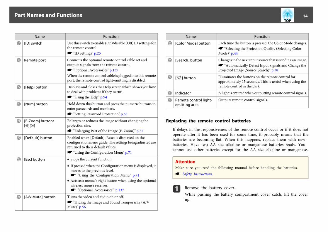
Y [Color Mode] button Each time the button is pressed, the Color Mode changes.s "Selecting the Projection Quality (Selecting ColorMode)" p.44
Z [Search] button Changes to the next input source that is sending an image.s "Automatically Detect Input Signals and Change theProjected Image (Source Search)" p.38
a [ ] button Illuminates the buttons on the remote control forapproximately 15 seconds. This is useful when using theremote control in the dark.
b Indicator A light is emitted when outputting remote control signals.
c Remote control light-emitting area
Outputs remote control signals.
Replacing the remote control batteries
If delays in the responsiveness of the remote control occur or if it does notoperate after it has been used for some time, it probably means that thebatteries are becoming flat. When this happens, replace them with newbatteries. Have two AA size alkaline or manganese batteries ready. Youcannot use other batteries except for the AA size alkaline or manganese.
AttentionMake sure you read the following manual before handling the batteries.s Safety Instructions
a Remove the battery cover.
While pushing the battery compartment cover catch, lift the coverup.
Part Names and Functions 14

b Replace the old batteries with new batteries.
CautionCheck the positions of the (+) and (-) marks inside the battery holder toensure the batteries are inserted the correct way.If the batteries are not used correctly, they could explode or leak causinga fire, injury, or damage to the product.
c Replace the battery cover.
Press the battery compartment cover until it clicks into place.
Remote control operating range
Part Names and Functions 15

a• To restrict reception of the operation signals from the remote
control, set Remote Receiver.s Settings - Remote Receiver p.77
• When using a remote control provided with other Epson projectors,set the Remote Control Type.s Extended - Operation - Remote Control Type p.78The operating range depends on the remote control that you use.
Part Names and Functions 16

Preparing the ProjectorThis chapter explains how to install the projector and connect projection sources.

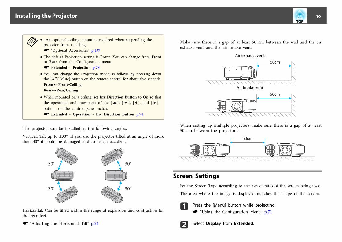
Installation RequirementsThe projector supports the following four different projection methods.Install the projector according to the conditions of the installation location.
• Project images from in front ofthe screen. (Front projection)
• Project images from behind a translucent screen. (Rear projec‐tion)
• Suspend the projector from theceiling and project images fromin front of a screen. (Front/Ceil‐ing projection)
• Suspend the projector from theceiling and project images frombehind a translucent screen.(Rear/Ceiling projection)
Warning• A special method of installation is required when suspending the projector
from a ceiling (ceiling mount). If installation work is not carried outcorrectly, the projector could fall down. This may result in injury oraccidents.Contact your dealer or the nearest address provided in the Support andService Guide if you want to use this installation method. s Epson ProjectorContact List
• If you use adhesives on the Ceiling mount fixing points to prevent the screwsfrom loosening, or if you use things such as lubricants or oils on theprojector, the projector case may crack causing it to fall from its ceilingmount. This could cause serious injury to anyone under the ceiling mountand could damage the projector.When installing or adjusting the ceiling mount, do not use adhesives toprevent the screws from loosening and do not use oils or lubricants and soon.
• Do not cover the projector's air intake vent or air exhaust vent. If either ofthe vents are covered, the internal temperature could rise and cause a fire.
AttentionDo not use the projector on its side. This may cause malfunctions to occur.
Installing the Projector 18
a• An optional ceiling mount is required when suspending the
projector from a ceiling.s "Optional Accessories" p.137
• The default Projection setting is Front. You can change from Frontto Rear from the Configuration menu.s Extended - Projection p.78
• You can change the Projection mode as follows by pressing downthe [A/V Mute] button on the remote control for about five seconds.FrontWFront/CeilingRearWRear/Ceiling
• When mounted on a ceiling, set Inv Direction Button to On so thatthe operations and movement of the [ ], [ ], [ ], and [ ]buttons on the control panel match.s Extended - Operation - Inv Direction Button p.78
The projector can be installed at the following angles.
Vertical: Tilt up to ±30°. If you use the projector tilted at an angle of morethan 30° it could be damaged and cause an accident.
30
30
30
30
Horizontal: Can be tilted within the range of expansion and contraction forthe rear feet.
s "Adjusting the Horizontal Tilt" p.24
Make sure there is a gap of at least 50 cm between the wall and the airexhaust vent and the air intake vent.
Air exhaust vent
Air intake vent
When setting up multiple projectors, make sure there is a gap of at least50 cm between the projectors.
Screen SettingsSet the Screen Type according to the aspect ratio of the screen being used.
The area where the image is displayed matches the shape of the screen.
a Press the [Menu] button while projecting.
s "Using the Configuration Menu" p.71
b Select Display from Extended.
Installing the Projector 19
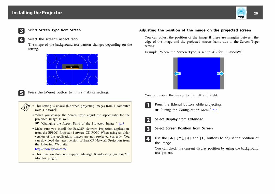
c Select Screen Type from Screen.
d Select the screen's aspect ratio.
The shape of the background test pattern changes depending on thesetting.
e Press the [Menu] button to finish making settings.
a• This setting is unavailable when projecting images from a computer
over a network.• When you change the Screen Type, adjust the aspect ratio for the
projected image as well.s "Changing the Aspect Ratio of the Projected Image " p.45
• Make sure you install the EasyMP Network Projection applicationfrom the EPSON Projector Software CD-ROM. When using an olderversion of the application, images are not projected correctly. Youcan download the latest version of EasyMP Network Projection fromthe following Web site.http://www.epson.com/
• This function does not support Message Broadcasting (an EasyMPMonitor plugin).
Adjusting the position of the image on the projected screen
You can adjust the position of the image if there are margins between theedge of the image and the projected screen frame due to the Screen Typesetting.
Example: When the Screen Type is set to 4:3 for EB-4950WU
You can move the image to the left and right.
a Press the [Menu] button while projecting.
s "Using the Configuration Menu" p.71
b Select Display from Extended.
c Select Screen Position from Screen.
d Use the [ ], [ ], [ ], and [ ] buttons to adjust the position ofthe image.
You can check the current display position by using the backgroundtest pattern.
Installing the Projector 20
e Press the [Menu] button to finish making settings.
aThe Screen Position cannot be adjusted in the following situations.• If the Screen Type is set to 16:10 when using EB-4955WU/
EB-4950WU/EB-4855WU/EB-4850WU/EB-4750W• If the Screen Type is set to 4:3 when using EB-4650/EB-4550
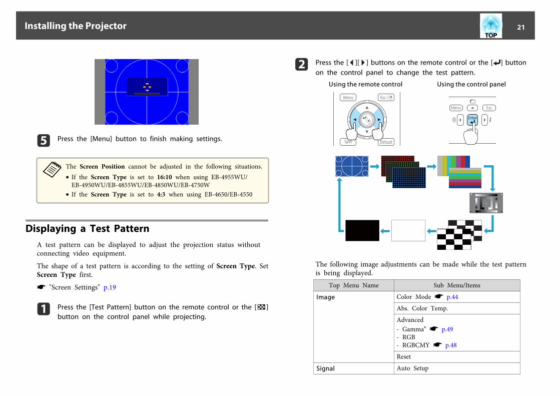
Displaying a Test PatternA test pattern can be displayed to adjust the projection status withoutconnecting video equipment.
The shape of a test pattern is according to the setting of Screen Type. SetScreen Type first.
s "Screen Settings" p.19
a Press the [Test Pattern] button on the remote control or the [ ]button on the control panel while projecting.
b Press the [ ][ ] buttons on the remote control or the [ ] buttonon the control panel to change the test pattern.
Using the remote control Using the control panel
The following image adjustments can be made while the test patternis being displayed.
Top Menu Name Sub Menu/Items
Image Color Mode s p.44
Abs. Color Temp.
Advanced- Gamma* s p.49- RGB- RGBCMY s p.48
Reset
Signal Auto Setup
Installing the Projector 21
Top Menu Name Sub Menu/Items
Settings Geometric Correction s p.40
Extended Multi-Projection- Multi-screen s p.50
* Except for custom settings of gamma
aTo set menu items that cannot be set while the test pattern isbeing displayed or to fine-tune the projected image, project animage from the connected device.
c Press the [Esc] button to close the test pattern.
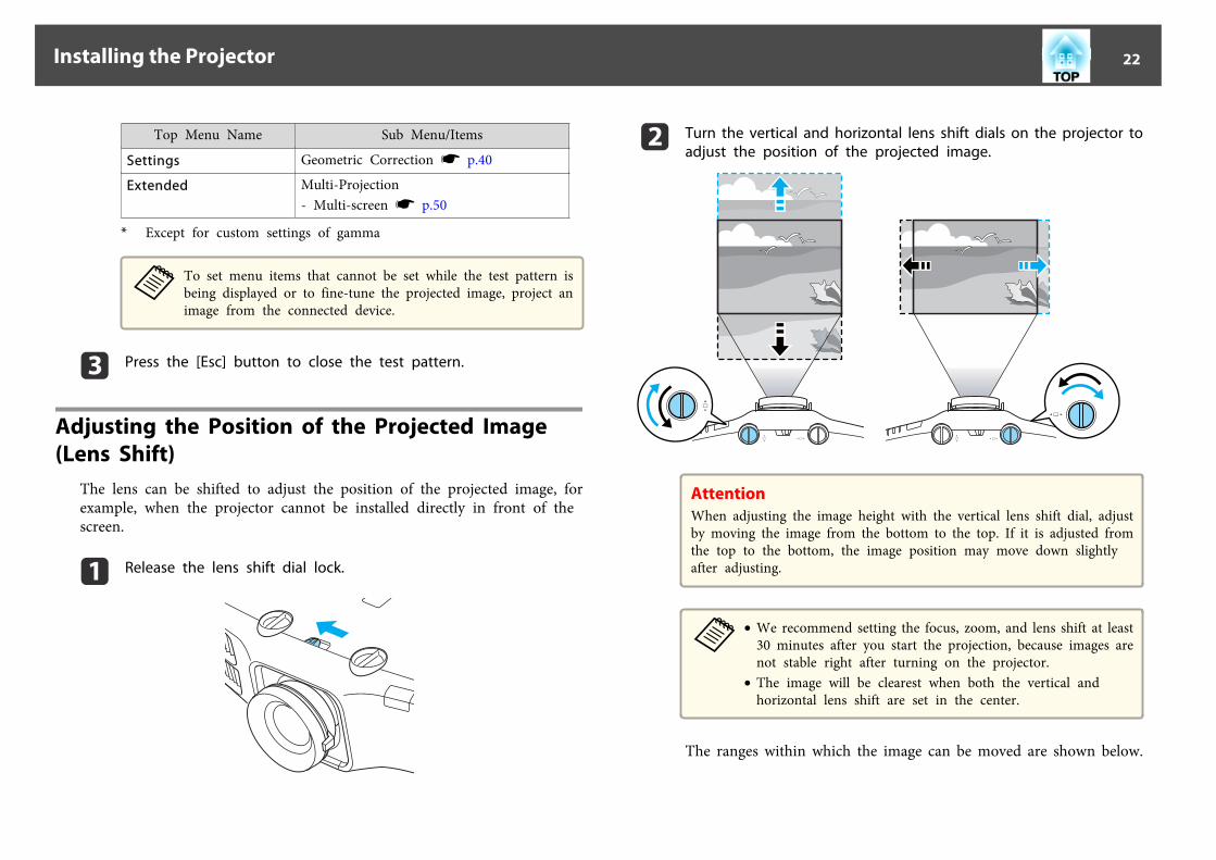
Adjusting the Position of the Projected Image (Lens Shift)
The lens can be shifted to adjust the position of the projected image, forexample, when the projector cannot be installed directly in front of thescreen.
a Release the lens shift dial lock.
b Turn the vertical and horizontal lens shift dials on the projector toadjust the position of the projected image.
AttentionWhen adjusting the image height with the vertical lens shift dial, adjustby moving the image from the bottom to the top. If it is adjusted fromthe top to the bottom, the image position may move down slightlyafter adjusting.
a• We recommend setting the focus, zoom, and lens shift at least
30 minutes after you start the projection, because images arenot stable right after turning on the projector.
• The image will be clearest when both the vertical andhorizontal lens shift are set in the center.
The ranges within which the image can be moved are shown below.
Installing the Projector 22

EB-4955WU/EB-4950WU/EB-4855WU/EB-4850WU
A Center of lensB Projected image when lens shift is set in the center
EB-4750W/EB-4650/EB-4550
A Center of lensB Projected image when lens shift is set in the center
The position of the projected image cannot be moved to both thehorizontal and vertical maximum values.
c When you have finished making adjustments, lock the lens shiftdial lock.
Installing the Projector 23
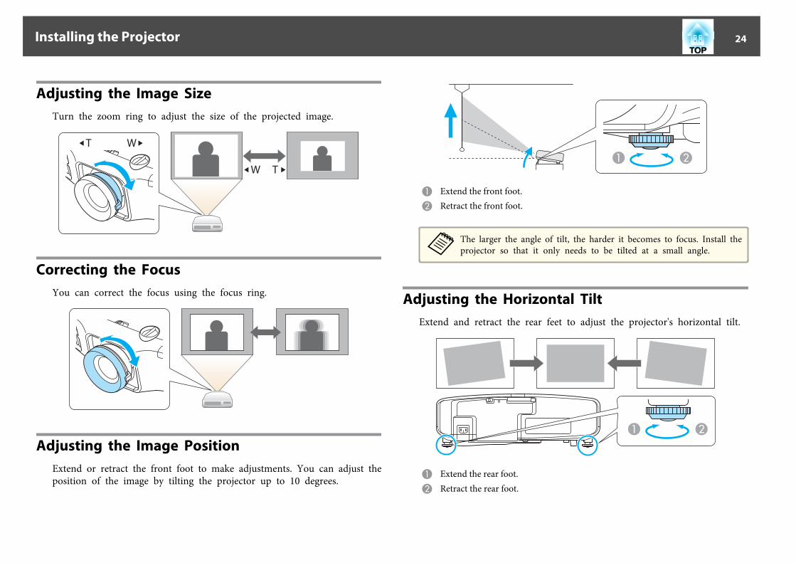
Adjusting the Image SizeTurn the zoom ring to adjust the size of the projected image.
W T
Correcting the FocusYou can correct the focus using the focus ring.
Adjusting the Image PositionExtend or retract the front foot to make adjustments. You can adjust theposition of the image by tilting the projector up to 10 degrees.
A Extend the front foot.B Retract the front foot.
aThe larger the angle of tilt, the harder it becomes to focus. Install theprojector so that it only needs to be tilted at a small angle.
Adjusting the Horizontal TiltExtend and retract the rear feet to adjust the projector's horizontal tilt.
A Extend the rear foot.B Retract the rear foot.
Installing the Projector 24
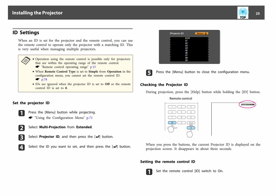
ID SettingsWhen an ID is set for the projector and the remote control, you can usethe remote control to operate only the projector with a matching ID. Thisis very useful when managing multiple projectors.
a• Operation using the remote control is possible only for projectors
that are within the operating range of the remote control.s "Remote control operating range" p.15
• When Remote Control Type is set to Simple from Operation in theconfiguration menu, you cannot set the remote control ID.s p.78
• IDs are ignored when the projector ID is set to Off or the remotecontrol ID is set to 0.
Set the projector ID
a Press the [Menu] button while projecting.
s "Using the Configuration Menu" p.71
b Select Multi-Projection from Extended.
c Select Projector ID, and then press the [ ] button.
d Select the ID you want to set, and then press the [ ] button.
e Press the [Menu] button to close the configuration menu.
Checking the Projector ID
During projection, press the [Help] button while holding the [ID] button.
Remote control
When you press the buttons, the current Projector ID is displayed on theprojection screen. It disappears in about three seconds.
Setting the remote control ID
a Set the remote control [ID] switch to On.
Installing the Projector 25

b While holding the [ID] button, press a number button to select anumber to match the ID of the projector you want to operate.
s "Checking the Projector ID" p.25Remote control
Once this setting has been made, the projector that can be operated by theremote control is limited.
aThe remote control ID setting is saved in the remote control. Even ifthe remote control batteries are removed to replace them and so on,the stored ID setting is retained. However, if the batteries are left outfor a long time, it is reset to the default value (ID0).
Setting the TimeYou can set the time for the projector. The set time is used by the schedulefunction.
s "Scheduling Function" p.62
a• When you turn on the projector for the first time, the message "Do
you want to set the time?" is displayed. When you select Yes, thescreen from step 4 is displayed.
• When Time/Schedule Protection is set to On in PasswordProtection, settings related to the date and time cannot be changed.You can make changes after setting Time/Schedule Protection toOff.s "Managing Users (Password Protection)" p.65
a Press the [Menu] button while projecting.
s "Using the Configuration Menu" p.71
b Select Operation from Extended.
c Select Date & Time, and then press the [ ] button.
d Make settings for the date and time.
Use the soft keyboard to enter the date and time.s "Soft keyboard operations" p.83
Installing the Projector 26
Date & Time
Submenu Function
Date Set today's date.
Time Set the current time.
Time Difference (UTC) Set the time difference from CoordinatedUniversal Time.
Set The settings made in Date & Time are applied.
Daylight Saving Time
Submenu Function
Daylight Saving Time Set whether or not (On/Off) to activate thedaylight saving time.DST Adjustment (min)adjusts the time difference between the standardtime and the daylight saving time.
DST Start Set the date and time to start the daylight savingtime.
DST End Set the date and time to end the daylight savingtime.
Set The settings made in Daylight Saving Time areapplied.
Internet Time
Submenu Function
Internet Time Set to On to update the time automatically throughan Internet time server.
Internet Time Server Input the IP address for an Internet time server.
Set The settings made in Internet Time are applied.
aWhen changing settings, make sure you select Set, and thenpress the [ ] button.
e Press the [Menu] button to finish making settings.
Installing the Projector 27

The port name, location, and connector orientation differ depending on the source being connected.
Connecting a ComputerTo project images from a computer, connect the computer using one of the following methods.
A When using the supplied computer cableConnect the computer's display output port to the projector's Computer port.You can output audio from the projector's speaker by connecting the audio output port on the computer to the projector's Audio1 port using a commercially available audio cable.
B When using a commercially available 5BNC cableConnect the computer's display output port to the projector's BNC port.You can output audio from the projector's speaker by connecting the audio output port on the computer to the projector's Audio2 port using a commercially available audio cable.
C When using a commercially available HDMI cableConnect the HDMI port on the computer to the projector's HDMI port.You can send the computer's audio with the projected image.
D When using a commercially available DisplayPort cableConnect the computer's DisplayPort to the projector's DisplayPort.You can send the computer's audio with the projected image.
Connecting Equipment 28

4
DisplayPort DisplayPort OUT
Computer
Audio1
Audio2
HDMI OUTHDMI
BNC
4
a• Change the audio output from Audio Settings.s Extended - A/V Settings - Audio Settings p.78
• If audio is not sent using an HDMI or DisplayPort cable, connect a commercially available audio cable to the Audio3 port to send the audio. Set HDMI AudioOutput or DisplayPort Audio Output to Audio3.s Extended - A/V Settings - Audio Settings - HDMI Audio Output, DisplayPort Audio Output p.78
• Some commercially available DisplayPort cables come with a lock. When removing the cable, press the button on the cable's connector section and pull out thecable.
Connecting Equipment 29

Connecting Image SourcesTo project images from DVD players or VHS video and so on, connect to the projector using one of the following methods.
A When using a commercially available video cableConnect the video output port on the image source to the projector's Video port.You can output audio from the projector's speaker by connecting the audio output port on the image source to the projector's Audio-L/R port using a commercially available audiocable.
B When using a commercially available S-video cableConnect the S-video output port on the image source to the projector's S-Video port.You can output audio from the projector's speaker by connecting the audio output port on the image source to the projector's Audio-L/R port using a commercially available audiocable.
C When using an optional component video cable (D-sub/component converter)s "Optional Accessories" p.137Connect the component output port on the image source to the projector's Computer port.You can output audio from the projector's speaker by connecting the audio output port on the video equipment to the projector's Audio1 port using a commercially available audiocable.
D When using a commercially available component video cable (RCA) and a BNC/RCA adapterConnect the component output port on the video equipment to the projector's BNC port (R/Cr/Pr, G/Y, B/Cb/Pb).You can output audio from the projector's speaker by connecting the audio output port on the video equipment to the projector's Audio2 port using a commercially available audiocable.
E When using a commercially available HDMI cableConnect the HDMI port on the image source to the projector's HDMI port.You can send the image source's audio with the projected image.
Connecting Equipment 30

5
4
Computer
Audio1
Video
Video
S-VideoS-Video
Audio-L/R
AUDIO OUT (L,R)
AUDIO OUT (L,R)
AUDIO OUT
AUDIO OUT
YCb/PbCr/Pr
YCb/PbCr/Pr
Audio2
HDMIHDMI OUT
BNC(R/Cr/Pr, G/Y, B/Cb/Pb)
5
Audio-L/R
4
Attention• If the input source is on when you connect it to the projector, it could cause a malfunction.• If the orientation or shape of the plug differs, do not try to force it in. The device could be damaged or could malfunction.
Connecting Equipment 31

a• Change the audio output from Audio Settings.s Extended - A/V Settings - Audio Settings p.78
• If audio is not sent using an HDMI cable, connect a commercially available audio cable to the Audio3 port to send the audio. Set HDMI Audio Output toAudio3.s Extended - A/V Settings - Audio Settings - HDMI Audio Output p.78
• If the source you want to connect to has an unusually shaped port, use the cable supplied with the device or an optional cable to connect to the projector.• When using a commercially available 2RCA(L/R)/stereo mini-pin audio cable, make sure it is labeled "No resistance".
Connecting External EquipmentYou can output images and audio by connecting an external monitor or speaker.
A When outputting images to an external monitorConnect the external monitor to the projector's Monitor Out port using the cable supplied with the external monitor.
B When outputting audio to an external speakerConnect the external speaker to the projector's Audio Out port using a commercially available audio cable.
Monitor Out D-Sub
Audio Out Audio IN
Connecting Equipment 32

a• Make the following settings to output image and audio even when the projector is in standby mode.
Set Standby Mode to Communication On.s Extended - Standby Mode p.78Set A/V Output to Always On.s Extended - A/V Settings - A/V Output p.78
• When the audio cable jack is inserted into the Audio Out port, audio stops being output from the projector's built-in speakers and switches to externaloutput.
Connecting a LAN CableConnect a LAN port on network hubs or other equipment to the projector's LAN port with a commercially available 100BASE-TX or 10BASE-T LANcable.
By connecting a computer to the projector over a network, you can project images and check the status of the projector.
LAN
The position of the LAN port differs depending on the model being used. s "Interface" p.9
aTo prevent malfunctions, use a category 5 or higher shielded LAN cable.
Connecting Equipment 33
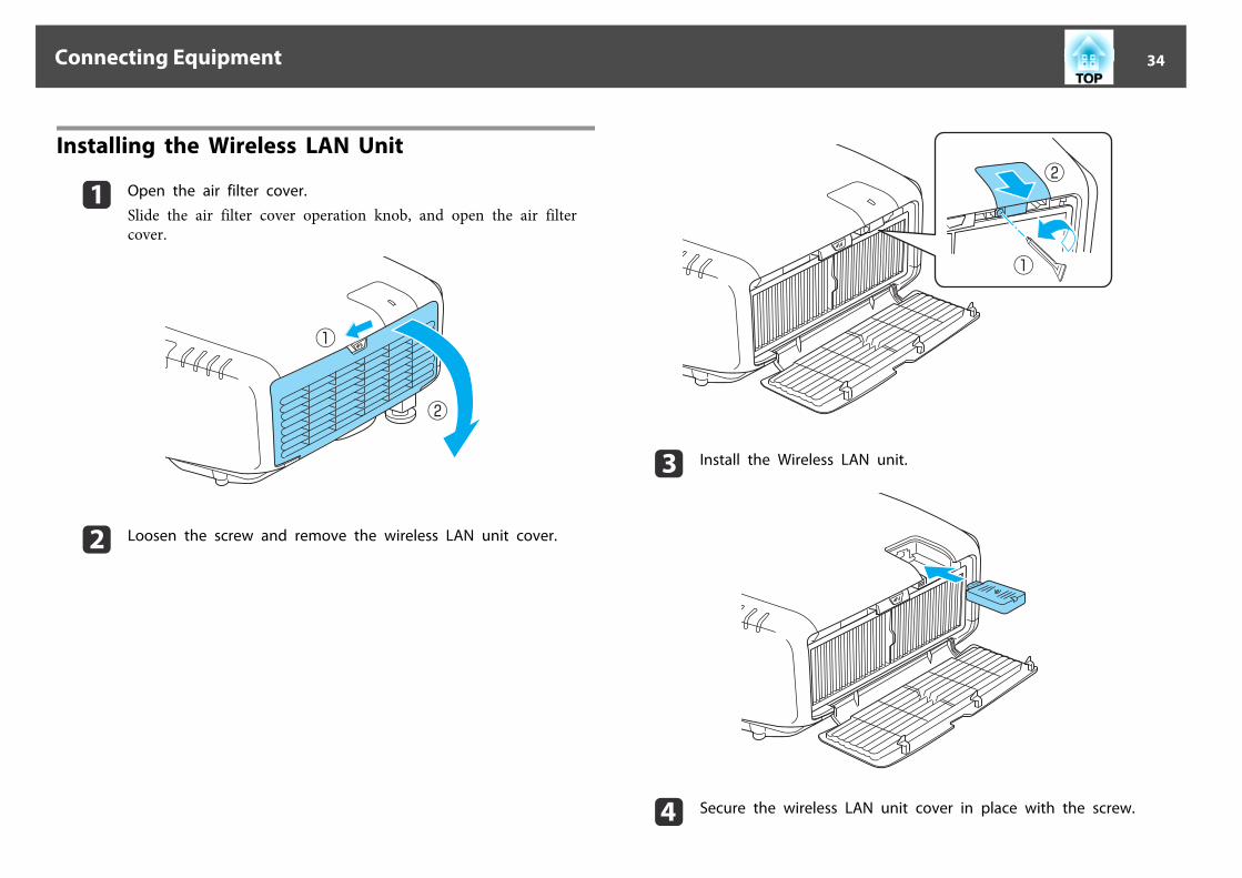
Installing the Wireless LAN Unit
a Open the air filter cover.
Slide the air filter cover operation knob, and open the air filtercover.
b Loosen the screw and remove the wireless LAN unit cover.
c Install the Wireless LAN unit.
d Secure the wireless LAN unit cover in place with the screw.
Connecting Equipment 34

e Close the air filter cover.
Attaching the Cable CoverBy attaching the cable cover, you can hide the connected cables giving anice, clean finish to the projector installation. (The illustrations are of aprojector installed on a ceiling.)
Attaching
a Bundle the cables together with a commercially available tie.
b Attach the cable cover to the rear of the projector.
c Tighten the screw on the cable cover. (You can tighten the screwswith your fingers.)
Connecting Equipment 35

Connecting Equipment 36

Basic UsageThis chapter explains how to project and adjust images.
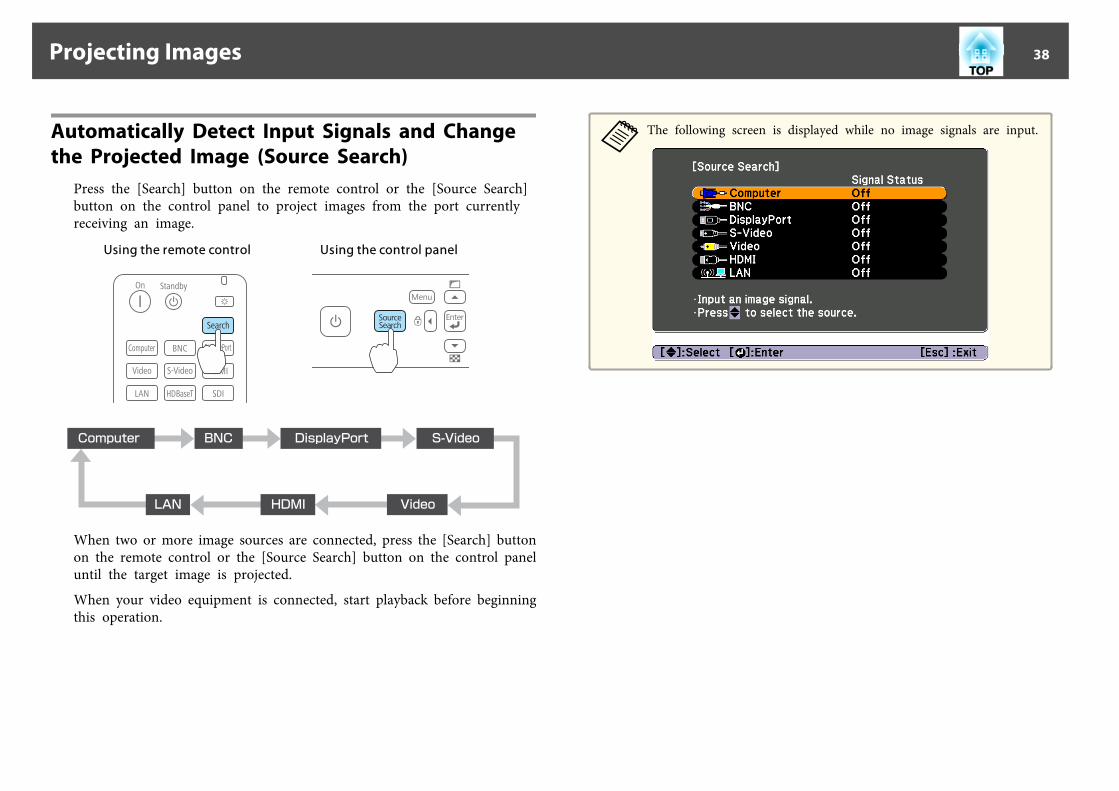
Automatically Detect Input Signals and Change the Projected Image (Source Search)
Press the [Search] button on the remote control or the [Source Search]button on the control panel to project images from the port currentlyreceiving an image.
Using the remote control Using the control panel
When two or more image sources are connected, press the [Search] buttonon the remote control or the [Source Search] button on the control paneluntil the target image is projected.
When your video equipment is connected, start playback before beginningthis operation.
aThe following screen is displayed while no image signals are input.
Projecting Images 38

Switching to the Target Image by Remote ControlYou can change directly to the target image by pressing the followingbuttons on the remote control.
The input ports for each button are shown below.
Remote control
Input Port
E Changes to images from a computer connected via the network. See the followingsection to check the position of the LAN port.s "Interface" p.9
Adjusting the VolumeYou can adjust the volume using one of the following methods.
• Press the [Volume] button on the remote control to adjust the volume.[a] Decreases the volume.[b] Increases the volume.
Remote control
• Adjust the volume from the Configuration menu.s Settings - Volume p.77
CautionDo not start at high volume.A sudden excessive volume may cause loss of hearing. Always lower the volumebefore powering off, so that you can power on and then gradually increase thevolume.
Projecting Images 39

Correcting Distortion in the Projected ImageYou can correct keystone distortion in projected images using one of thefollowing methods.
• H/V-KeystoneManually correct distortion in the horizontal and vertical directionsindependently.s "H/V-Keystone" p.40
• Quick CornerManually correct the four corners independently.s "Quick Corner" p.41
• Arc CorrectionFine adjustment of the curved distortion caused by slack or shrinkage ofthe screen.s "Arc Correction" p.42
• Point CorrectionFine adjustment of small distortions.s "Point Correction" p.43
a • By pressing the [ ] button on the control panel, you can performthe selected adjustment method directly.
• You cannot combine multiple adjustment methods.
H/V-Keystone
Manually correct distortion in the horizontal and vertical directionsindependently. Distortion can be corrected when the angle of vertical andhorizontal tilt of the projector is up to 30 degrees against the screen.
a Press the [Menu] button while projecting.
b Select Geometric Correction from Settings.
Adjusting Projected Images 40

c Select H/V-Keystone, and then press the [ ] button.
If the message "If this setting is changed, the image may bedistorted." is displayed, press the [ ] button.
d Use the [ ][ ] buttons to select the correction method, and
then use the [ ][ ] buttons to make the corrections.
V-Keystone
H-Keystone
aWhen you correct keystone distortion, the projected image maybe reduced.
e When you are done, press the [Menu] button to exit the correctionmenu.
Quick Corner
This allows you to manually correct each of the four corners of theprojected image separately.
a Press the [Menu] button while projecting.
b Select Geometric Correction from Settings.
c Select Quick Corner, and then press the [ ] button.
If the message "If this setting is changed, the image may bedistorted." is displayed, press the [ ] button.
d Use the [ ], [ ], [ ], and [ ] buttons to select the corner youwant to adjust, and then press the [ ] button.
Adjusting Projected Images 41

aIf the [Esc] button is pressed for at least 2 seconds, the confirmdefault reset screen is displayed.Select Yes to reset the result of Quick Corner corrections.
e Use the [ ], [ ], [ ], and [ ] buttons to correct the position ofthe corner.
When you press the [ ] button, the screen shown in step 4 thatallows you to select the area to be corrected is displayed.If the message "Cannot adjust any further." is displayed whileadjusting, you cannot adjust the shape any further in the directionindicated by the gray triangle.
f Repeat procedures 4 and 5 as needed to adjust any remainingcorners.
g When you are done, press the [Menu] button to exit the correctionmenu.
Arc Correction
a Press the [Menu] button while projecting.
b Select Geometric Correction from Settings.
c Select Arc Correction, and then press the [ ] button.
If the message "If this setting is changed, the image may bedistorted." is displayed, press the [ ] button.
d Use the [ ], [ ], [ ], and [ ] buttons to select the area youwant to adjust, and then press the [ ] button.
When selecting a corner, you can adjust the two sides next to thecorner.
aIf the [Esc] button is pressed for at least 2 seconds, the confirmdefault reset screen is displayed.Select Yes to reset the result of Arc Correction.
e Use the [ ], [ ], [ ], and [ ] buttons to adjust the shape.
Adjusting Projected Images 42

If the triangle in the direction you are adjusting the shape turns gray,as shown in the screenshot below, you cannot adjust the shape anyfurther in that direction.
f Press the [Esc] button to return to the previous screen.
g Repeat procedures from 4 to 6 as needed to adjust any remainingparts.
h When you are done, press the [Menu] button to exit the correctionmenu.
Point Correction
Divides the projected image by the grid and corrects the distortion bymoving the point of intersection from side to side and up and down.
a Press the [Menu] button while projecting.
b Select Geometric Correction from Settings.
c Select Point Correction, and then press the [ ] button.
If the message "If this setting is changed, the image may bedistorted." is displayed, press the [ ] button.
d Select Point Correction, and then press the [ ] button.
Point Correction: Performs point correction.Pattern Color: Select the color of the grid when performingcorrections.Reset: Resets all corrections for Point Correction to their defaultvalues.
e Select the number of grid lines (3x3, 5x5, or 9x9), and then pressthe [ ] button.
f Use the [ ], [ ], [ ], and [ ] buttons to move to the point youwant to correct, and then press the [ ] button.
Adjusting Projected Images 43

g Use the [ ], [ ], [ ], and [ ] buttons to correct distortion.
To continue to correct another point, press the [Esc] button toreturn to the previous screen, and then repeat steps 6 and 7.
aEach time you press the [ ] button, you can show or hide theimage and the grid.
h When you are done, press the [Menu] button to exit the correctionmenu.
Selecting the Projection Quality (Selecting Color Mode)
You can easily obtain the optimum image quality simply by selecting thesetting that best corresponds to your surroundings when projecting. Thebrightness of the image varies depending on the mode selected.
Mode Application
Dynamic Ideal for use in a bright room. This is the brightestmode.
Presentation Ideal for making presentations using color materialsin a bright room.
Theatre Ideal for watching films in a dark room. Givesimages a natural tone.
Photo*1 Ideal for projecting still pictures, such as photos, ina bright room. The images are vivid and broughtinto contrast.
Sports*2 Ideal for watching TV programmes in a brightroom. The images are vivid and brought to life.
sRGB Ideal for images that conform to the sRGBg colorstandard.
DICOM SIM*1 Ideal for projecting X-ray photographs and othermedical images. This produces images with clearshadows. The projector is not a medical device andcannot be used for medical diagnosis.
Multi-Projection Ideal for projecting from multiple projectors.Minimize the color tone difference between eachprojected image.
*1 This can only be selected when inputting RGB signals, or when LAN isselected as the input source.
*2 This can only be selected when inputting component video signals, or whenthe source is Video or S-Video.
Adjusting Projected Images 44
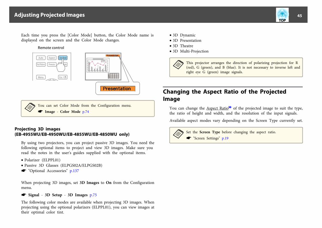
Each time you press the [Color Mode] button, the Color Mode name isdisplayed on the screen and the Color Mode changes.
Remote control
aYou can set Color Mode from the Configuration menu.s Image - Color Mode p.74
Projecting 3D images(EB-4955WU/EB-4950WU/EB-4855WU/EB-4850WU only)
By using two projectors, you can project passive 3D images. You need thefollowing optional items to project and view 3D images. Make sure youread the notes in the user's guides supplied with the optional items.
• Polarizer (ELPPL01)• Passive 3D Glasses (ELPGS02A/ELPGS02B)s "Optional Accessories" p.137
When projecting 3D images, set 3D Images to On from the Configurationmenu.
s Signal - 3D Setup - 3D Images p.75
The following color modes are available when projecting 3D images. Whenprojecting using the optional polarizers (ELPPL01), you can view images attheir optimal color tint.
• 3D Dynamic• 3D Presentation• 3D Theatre• 3D Multi-Projection
aThis projector arranges the direction of polarizing projection for R(red), G (green), and B (blue). It is not necessary to inverse left andright eye G (green) image signals.
Changing the Aspect Ratio of the Projected Image
You can change the Aspect Ratiog of the projected image to suit the type,the ratio of height and width, and the resolution of the input signals.
Available aspect modes vary depending on the Screen Type currently set.
aSet the Screen Type before changing the aspect ratio.s "Screen Settings" p.19
Adjusting Projected Images 45
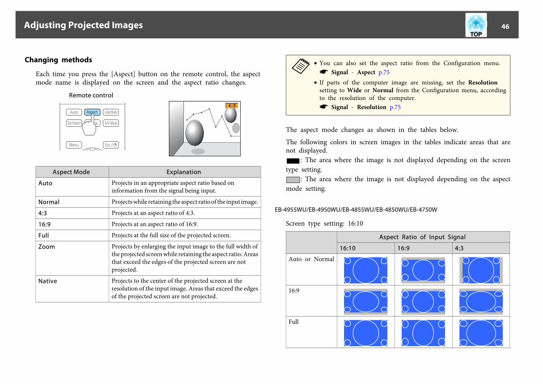
Changing methods
Each time you press the [Aspect] button on the remote control, the aspectmode name is displayed on the screen and the aspect ratio changes.
Remote control
Aspect Mode Explanation
Auto Projects in an appropriate aspect ratio based oninformation from the signal being input.
Normal Projects while retaining the aspect ratio of the input image.
4:3 Projects at an aspect ratio of 4:3.
16:9 Projects at an aspect ratio of 16:9.
Full Projects at the full size of the projected screen.
Zoom Projects by enlarging the input image to the full width ofthe projected screen while retaining the aspect ratio. Areasthat exceed the edges of the projected screen are notprojected.
Native Projects to the center of the projected screen at theresolution of the input image. Areas that exceed the edgesof the projected screen are not projected.
a• You can also set the aspect ratio from the Configuration menu.s Signal - Aspect p.75
• If parts of the computer image are missing, set the Resolutionsetting to Wide or Normal from the Configuration menu, accordingto the resolution of the computer.s Signal - Resolution p.75
The aspect mode changes as shown in the tables below.
The following colors in screen images in the tables indicate areas that arenot displayed.
: The area where the image is not displayed depending on the screentype setting.
: The area where the image is not displayed depending on the aspectmode setting.
EB-4955WU/EB-4950WU/EB-4855WU/EB-4850WU/EB-4750W
Screen type setting: 16:10
Aspect Ratio of Input Signal
16:10 16:9 4:3
Auto or Normal
16:9
Full
Adjusting Projected Images 46

Aspect Ratio of Input Signal
16:10 16:9 4:3
Zoom
Native*
* The image may differ depending on the resolution of the input signal.
Screen type setting: 16:9
Aspect Ratio of Input Signal
16:10 16:9 4:3
Auto or Normal
Full
Zoom
Native*
* The image may differ depending on the resolution of the input signal.
Screen type setting: 4:3
Aspect Ratio of Input Signal
16:10 16:9 4:3
Auto or Normal
4:3
16:9
Native*
* Only computer images and images from the HDMI port. The image may differdepending on the resolution of the input signal.
EB-4650/EB-4550
Screen type setting: 4:3
Aspect Ratio of Input Signal
16:10 16:9 4:3
Auto or Normal
4:3
16:9
Adjusting Projected Images 47

Aspect Ratio of Input Signal
16:10 16:9 4:3
Native*
* Only computer images and images from the HDMI port. The image may differdepending on the resolution of the input signal.
Screen type setting: 16:9
Aspect Ratio of Input Signal
16:10 16:9 4:3
Auto or Normal
Full
Zoom
Native*
* The image may differ depending on the resolution of the input signal.
Screen type setting: 16:10
Aspect Ratio of Input Signal
16:10 16:9 4:3
Auto or Normal
Aspect Ratio of Input Signal
16:10 16:9 4:3
16:9
Full
Zoom
Native*
* The image may differ depending on the resolution of the input signal.
Adjusting the Image
Hue, Saturation, and Brightness Adjustment
The Hue, Saturation, and Brightness for each of the R (red), G (green), B(blue), C (cyan), M (magenta) and Y (yellow) color components can beadjusted.
Make settings from the configuration menu.
s Image - Advanced - RGBCMY p.74
Adjusting Projected Images 48

Gamma Adjustment
Adjusts differences in the coloring for the projected image that occursdepending on the connected device.
Make settings from the configuration menu.
s Image - Advanced - Gamma p.74
Select and adjust the correction value
s Image - Advanced - Gamma p.74
When a smaller value is selected, the dark areas of images become brighter,but the color saturation for lighter areas may become weaker. When a
larger value is selected, you can reduce the overall brightness of the imageto make the image sharper.
If you select DICOM SIM from Color Mode on the Image menu, select theadjustment value according to the projection size.
• If the projection size is 120 inches or less, select a large value.• If the projection size is 120 inches or more, select a small value.
aMedical images may not be reproduced correctly according to yoursettings and screen specifications.
Adjust while viewing the image
s Image - Advanced - Gamma - Customized - Adjust it from the imagep.74
Move the cursor on the projected image to the part where you want tochange the brightness, then press the [ ] button. Use the [ ][ ] buttonsto adjust the value.
Adjusting Projected Images 49

Adjust using the gamma adjustment graph
s Image - Advanced - Gamma - Customized - Adjust it from the graphp.74
Adjust while looking at the gamma adjustment graph.
Correcting the Color Difference when Projecting from Multiple Projectors
When multiple projectors are lined up and projecting images, you cancorrect the brightness and color tone of each projector's image with multi-
screen color adjustment so that the colors of images from each projectormatch closely.
aIn some cases the brightness and color tone may not match completelyeven after correction.
Summary of correction procedure
When multiple projectors are set up and you need to make corrections, usethe following procedure to correct one projector at a time.
1. Set the projector IDSet a unique projector ID for the target projector so that you can limit whichprojector is being corrected.s "ID Settings" p.25
2. Correct the color difference.You can carry out color correction when projecting from multiple projectors.You can adjust from black to white in five stages called levels 1 to 5, and ineach of these five levels you can adjust the following two points.• Correcting brightness
You can correct the image brightness to make them all equal.
• Correcting colorYou can correct the image color so that they match closely.
Correcting
a Press the [Menu] button while projecting.
b Select Multi-Projection from Extended.
c Select Multi-screen, and then press the [ ] button.
The following screen is displayed.
Adjusting Projected Images 50

Adjustment Level: There are five levels from white, gray, and up toblack. Adjust each level individually.Brightness Correct.: Adjust from black to white for each color tone.Color Correct. (G/R): Adjust the color tone for green and red.Color Correct. (B/Y): Adjust the color tone for blue and yellow.
d Select Adjustment Level, and then use the [ ][ ] buttons to setthe adjustment level.
e Select Brightness Correct., and then use the [ ][ ] buttons toadjust the brightness.
f Select Color Correct. (G/R) or Color Correct. (B/Y), and then usethe [ ][ ] buttons to adjust the color.
g Return to step 4 and adjust each level.
h When you are done, press the [Menu] button to exit the correctionmenu.
Adjusting Projected Images 51

Useful FunctionsThis chapter explains useful tips for giving presentations, and the Security functions.

Projecting Two Images Simultaneously (Split Screen)
You can simultaneously project images from two sources on the right andleft of the screen.
a• The following input source combinations cannot be projected using
the split screen function.Computer - BNC, S-Video - VideoAlso, when using EB-4955WU/EB-4950WU/EB-4855WU/EB-4850WU, you cannot project images from the LAN source(images from a computer over a network) using split screen.
• You cannot project the same input source on both sides (left andright) of the screen.
Operating procedures
Projecting on a split screen
a Press the [Split] button while projecting.
The currently selected input source is projected on the left of thescreen.
Remote control
aYou can perform the same operations from the configurationmenu.s Settings - Split Screen p.77
b Press the [Menu] button.
The Split Screen Setup screen is displayed.
c Select Source, and then press the [ ] button.
Projection Functions 53

d Select each input source for Left and Right.
aYou can perform the same operations using the followingprocedure.s "Automatically Detect Input Signals and Change theProjected Image (Source Search)" p.38s "Switching to the Target Image by Remote Control" p.39
e Select Execute, and then press the [ ] button.
To switch the source during split screen projection, start theprocedure from step 2.
Switching the left and right screens
Use the following procedure to switch the projected images displayed onthe left and right screens.
a Press the [Menu] button during split screen projection.
b Select Swap Screens, and then press the [ ] button.
The projected images on the left and right are swapped.
Switching the left and right image sizes
a Press the [Menu] button during split screen projection.
b Select Screen Size, and then press the [ ] button.
c Select the screen size you want to display, and then press the [ ]button.
Projection Functions 54

The projected images will appear as shown below after setting the screensize.
Equal Larger Left
Larger Right
a• You cannot enlarge both the left screen and right screen images at
the same time.• When one image is enlarged, the other image is reduced.• Depending on the video signals that are input, the images on the left
and right may not appear to be the same size even if Equal isset.
Changing the audio
a Press the [Menu] button during split screen projection.
b Select Audio Source, and then press the [ ] button.
c Select the audio you want to output, and then press the [ ]button.
When you select Auto, audio is output for the largest screen.If the screens are the same size, audio is output for the screen on theleft.
Ending the split screen
Press the [Esc] button to end split screen.The following steps can also be used to end the split screen.
• Press the [Split] button on the remote control.• Select Exit Split Screen on the Split Screen Setup screen. s p.53
Restrictions during split screen projection
Operating restrictions
The following operations cannot be performed during split screenprojection.
• Setting the configuration menu• E-Zoom• Changing the aspect mode• Using the [User1], [User2], or [User3] buttons on the remote control• Help can be displayed only when image signals are not input or when
an error or warning notification is displayed.
Projection Functions 55

• The user's logo is not displayed.
Restriction relating to images
• The default values for the Image menu are applied to the image on theright screen. However, the settings for the image projected on the leftscreen are applied to the image on the right screen for Color Mode,Abs. Color Temp., and Advanced.
• Auto Iris is not available.s Image - Auto Iris p.74
Hiding the Image and Sound Temporarily (A/V Mute)
You can use this when you want to focus the audience's attention on whatyou are saying, or if you do not want to show details such as when you arechanging between files during presentations from a computer.
A/V Mute is applied or released each time you press the [A/V Mute]button.
Remote control
a• When A/V Mute Release is set to A/V Mute from the configuration
menu, the following operations can still be performed withoutreleasing A/V mute.s Extended - Operation - A/V Mute Release p.78- Change the source with the change input buttons on the remotecontrol.s "Switching to the Target Image by Remote Control" p.39- Control the projector from a computer using communicationcommands.s "Monitoring and Controlling" p.127A/V mute is only released by pressing the [A/V Mute] button, or bysending an A/V mute Off command.
• When projecting moving images, the images and sound continue tobe played back while A/V Mute is on. It is not possible to resumeprojection from the point where A/V Mute was activated.
• You can select the screen displayed when the [A/V Mute] button ispressed from the Configuration menu.s Extended - Display - A/V Mute p.78
• The lamp is still lit during A/V Mute, so the lamp hours continue toaccumulate.
Projection Functions 56

Freezing the Image (Freeze)When Freeze is activated on moving images, the frozen image continues toproject on the screen, so you can project a moving image one frame at atime like a still photo. Also, you can perform operations such as changingbetween files during presentations from a computer without projecting anyimages if the Freeze function is activated beforehand.
Each time you press the [Freeze] button, Freeze turns on or off.
Remote control
a• Audio does not stop.• When projecting moving images, the images continue to be played
back while the screen is frozen. It is not possible to resumeprojection from the point where the screen was frozen.
• If the [Freeze] button is pressed while the Configuration menu orthe Help screen is displayed, the menu or the Help screen that isdisplayed is closed.
• Freeze still works while E-Zoom is being used.
Enlarging Part of the Image (E-Zoom)This is useful when you want to expand images to see them in greaterdetail, such as graphs and tables.
a Start E-Zoom.
Press the [z] button to display the Cross ( ).
Remote control
b Move the Cross ( ) to the area of the image that you want to
enlarge.
Remote control
Projection Functions 57

c Enlarge.
Remote control[z] button: Expands the area each timeit is pressed. You can expand quickly byholding the button down.[x] button: Reduces images that havebeen enlarged.[Esc] button: Cancels E-Zoom.
a During enlarged projection, press the [ ], [ ], [ ], or [ ]buttons to scroll the image.
Saving a User's LogoYou can save the image that is currently being projected as a User's Logo.
aOnce a User's Logo has been saved, the logo cannot be returned to thefactory default.
a Project the image you want to save as the User's Logo, and thenpress the [Menu] button.
s "Using the Configuration Menu" p.71
b Select User's Logo from Extended.
a• When User's Logo Protection from Password Protection is
set to On, a message is displayed and the User's Logo cannotbe changed. You can make changes after setting User's LogoProtection to Off.s "Managing Users (Password Protection)" p.65
• If User's Logo is selected when Geometric Correction, E-Zoom or Aspect are being performed, the function currentlybeing performed is temporarily cancelled.
c When the message "Choose this image as the User's Logo?" isdisplayed, select Yes.
a When you press the [ ] button, the screen size may changedepending on the signal to match the actual resolution of theimage signal.
d Move the box to select the part of the image to use as the User'sLogo.
You can perform the same operations from the projector's controlpanel.
Remote control
aYou can save at 400x300 dots in size.
Projection Functions 58

e When you press the [ ] button and the message "Select thisimage?" is displayed, select Yes.
f Select the zoom factor from the zoom setting screen.
g When the message "Save this image as the User's Logo?" isdisplayed, select Yes.
The image is saved. After the image has been saved, the message"Completed." is displayed.
aWhen a User's Logo is saved, the previous User's Logo iserased.
Projection Functions 59

The settings for the image currently displayed are saved as a memory,allowing you to load them when necessary. Settings for the following menuitems are saved in the memory.
Top Menu Submenu
Image All setting items
Signal 3D SetupProgressiveNoise ReductionMosquito NRVideo RangeOverscanImage Processing
Settings Power Consumption
Extended Multi-Projection- Multi-screen
Saving/Loading/Erasing the Memory
a Press the [Menu] button while an image is being displayed.
s "Using the Configuration Menu" p.71
b Select Memory from Settings.
c Select the function you want to perform, then press the [ ]button.
You can only perform Load Memory and Save Memory when animage is displayed.
Memory Function 60

Function Explanation
Load Memory Loads the saved memory. When you select amemory and press the [ ] button, the settingsapplied to the current image are replaced with thesettings from the memory.
Save Memory The settings for the image currently displayed aresaved as a memory. When you select a memoryname and press the [ ] button, the settings aresaved.
Erase Memory Erases the registered memory. When you select amemory name and press the [ ] button, amessage is displayed. Select Yes, and then press the[ ] button to erase the selected memory. You canerase all memories from Reset Memory.s Reset - Reset Memory p.90
Function Explanation
Rename Memory Changes the memory name. Select the memoryname you want to change, and then press the [ ]button. Enter the memory name using the softkeyboard.s "Soft keyboard operations" p.83When you have finished, move the cursor overFinish, and then press the [ ] button.
When a memory has already been saved, the memory name and itscolor mode are displayed.
aIf the mark on the left of the memory name is turned green, itmeans the memory has already been registered. When youselect a registered memory, a message is displayed asking you toconfirm that you want to overwrite the memory. If you selectYes, the previous settings are deleted and the current settingsare registered.
Memory Function 61

You can schedule turning the projector power on/off and switching theinput source, as events in the schedule. Registered events are executedautomatically at the specified time on the specified dates or weekly.
WarningDo not place flammable objects in front of the lens. If you set the schedule toturn on the projector automatically, any flammable objects placed in front ofthe lens could cause a fire.
Saving a Schedule
a• You can set or adjust the date and time for the projector in Date &
Time from the configuration menu.s "Setting the Time" p.26
• When Time/Schedule Protection is set to On in PasswordProtection, settings related to the scheduling function cannot bechanged. You can make changes after setting Time/ScheduleProtection to Off.s "Managing Users (Password Protection)" p.65
Setting Methods
a Press the [Menu] button while projecting.
s "Using the Configuration Menu" p.71
b Select Schedule Settings from Extended.
c Select Add New from Schedule.
d Set the schedule.
Submenu Name Function
Event Settings Select an operation of the projector when the eventis executed. Select No Change for items that you donot want to change when the event occurs.You can set the following item operations.• Power• Source• Power Consumption• A/V Mute• Volume
Date / Time Settings Set the date, day of the week, and time to executethe event. Use the soft keyboard to enter the dateand time.s "Soft keyboard operations" p.83When you have finished, move the cursor overFinish, and then press the [ ] button.
Scheduling Function 62

e Select Save, and then press the [ ] button.
To register additional schedules, repeat steps 3 to 5.
f Select Setup complete, and then select Yes to finish saving.
aA calendar is displayed on the Schedule Settings screen (the screen instep 3). The indicator turns on when an event is saved. ( : one-time
event; : periodic event; : communication on/off; : eventinvalid)
Use the [ ][ ] buttons to highlight and check the scheduleregistered for that day.
Editing a schedule
a Press the [Menu] button while projecting.
s "Using the Configuration Menu" p.71
b Select Schedule Settings from Extended.
c Use the [ ][ ] buttons to highlight the date containing theschedule you want to edit.
d Highlight the schedule you want to edit, and then press the [Esc]button.
Scheduling Function 63

aA repeat icon is displayed for periodic schedules.
e Perform editing from the menu displayed.
Submenu Name Function
On/Off Enable or disable the selected schedule. When aschedule is enabled, the indicator turns green.
Edit Edit the content of the selected schedule. SelectSave, and then press the [ ] button to completethe editing.
Clear Deletes the selected schedule.
Add New Save a new schedule. Select Save, and then press the[ ] button to complete the saving.
f Select Setup complete, and then select Yes to finish editing.
aTo delete all registered schedules, select Schedule Reset, andthen select Yes. Select Setup complete, and then select Yes todelete the schedules.
Scheduling Function 64
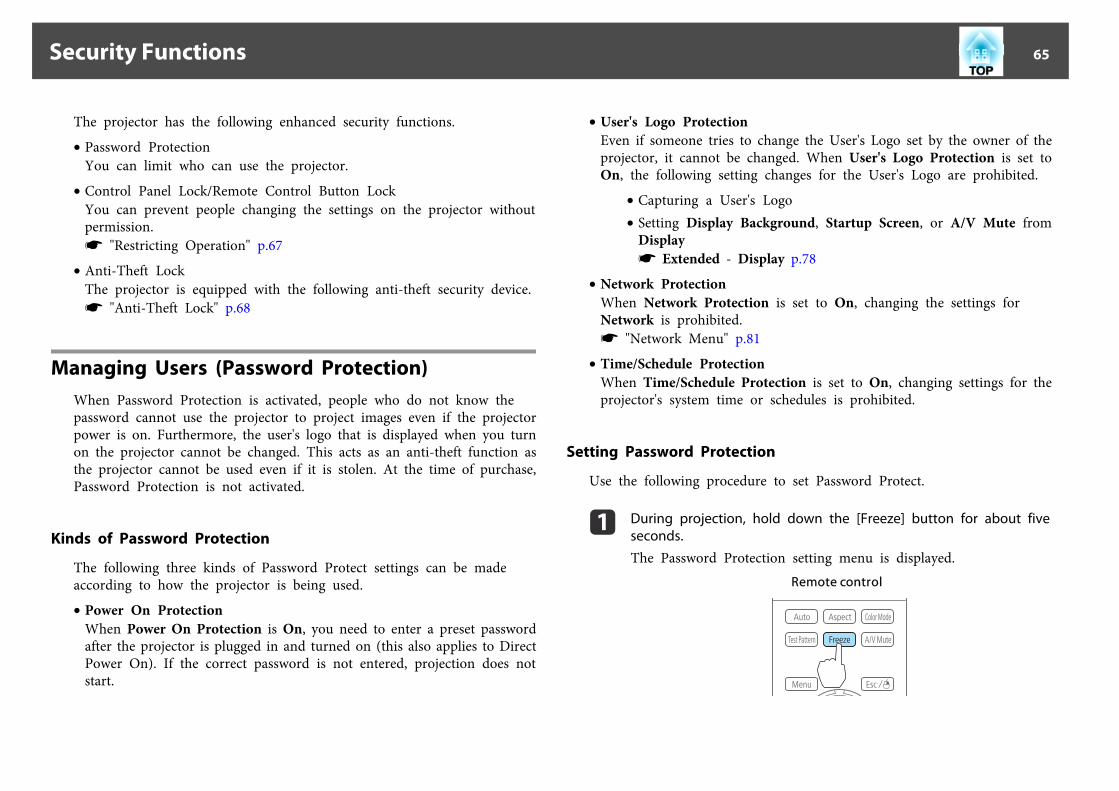
The projector has the following enhanced security functions.
• Password ProtectionYou can limit who can use the projector.
• Control Panel Lock/Remote Control Button LockYou can prevent people changing the settings on the projector withoutpermission.s "Restricting Operation" p.67
• Anti-Theft LockThe projector is equipped with the following anti-theft security device.s "Anti-Theft Lock" p.68
Managing Users (Password Protection)When Password Protection is activated, people who do not know thepassword cannot use the projector to project images even if the projectorpower is on. Furthermore, the user's logo that is displayed when you turnon the projector cannot be changed. This acts as an anti-theft function asthe projector cannot be used even if it is stolen. At the time of purchase,Password Protection is not activated.
Kinds of Password Protection
The following three kinds of Password Protect settings can be madeaccording to how the projector is being used.
• Power On ProtectionWhen Power On Protection is On, you need to enter a preset passwordafter the projector is plugged in and turned on (this also applies to DirectPower On). If the correct password is not entered, projection does notstart.
• User's Logo ProtectionEven if someone tries to change the User's Logo set by the owner of theprojector, it cannot be changed. When User's Logo Protection is set toOn, the following setting changes for the User's Logo are prohibited.
• Capturing a User's Logo• Setting Display Background, Startup Screen, or A/V Mute from
Displays Extended - Display p.78
• Network ProtectionWhen Network Protection is set to On, changing the settings forNetwork is prohibited.s "Network Menu" p.81
• Time/Schedule ProtectionWhen Time/Schedule Protection is set to On, changing settings for theprojector's system time or schedules is prohibited.
Setting Password Protection
Use the following procedure to set Password Protect.
a During projection, hold down the [Freeze] button for about fiveseconds.
The Password Protection setting menu is displayed.Remote control
Security Functions 65
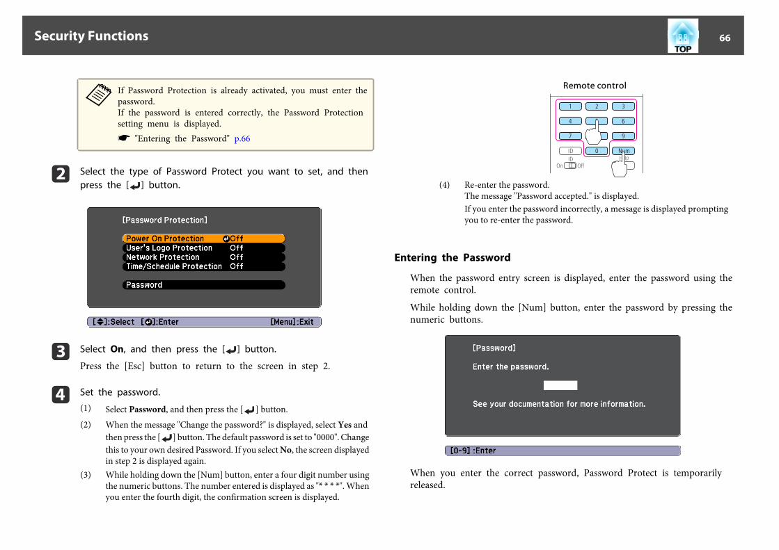
aIf Password Protection is already activated, you must enter thepassword.If the password is entered correctly, the Password Protectionsetting menu is displayed.s "Entering the Password" p.66
b Select the type of Password Protect you want to set, and thenpress the [ ] button.
c Select On, and then press the [ ] button.
Press the [Esc] button to return to the screen in step 2.
d Set the password.
(1) Select Password, and then press the [ ] button.(2) When the message "Change the password?" is displayed, select Yes and
then press the [ ] button. The default password is set to "0000". Changethis to your own desired Password. If you select No, the screen displayedin step 2 is displayed again.
(3) While holding down the [Num] button, enter a four digit number usingthe numeric buttons. The number entered is displayed as "* * * *". Whenyou enter the fourth digit, the confirmation screen is displayed.
Remote control
(4) Re-enter the password.The message "Password accepted." is displayed.If you enter the password incorrectly, a message is displayed promptingyou to re-enter the password.
Entering the Password
When the password entry screen is displayed, enter the password using theremote control.
While holding down the [Num] button, enter the password by pressing thenumeric buttons.
When you enter the correct password, Password Protect is temporarilyreleased.
Security Functions 66
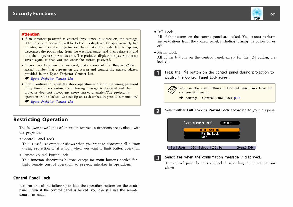
Attention• If an incorrect password is entered three times in succession, the message
"The projector's operation will be locked." is displayed for approximately fiveminutes, and then the projector switches to standby mode. If this happens,disconnect the power plug from the electrical outlet and then reinsert it andturn the projector's power back on. The projector displays the password entryscreen again so that you can enter the correct password.
• If you have forgotten the password, make a note of the "Request Code:xxxxx" number that appears on the screen and contact the nearest addressprovided in the Epson Projector Contact List.s Epson Projector Contact List
• If you continue to repeat the above operation and input the wrong passwordthirty times in succession, the following message is displayed and theprojector does not accept any more password entries."The projector'soperation will be locked. Contact Epson as described in your documentation."s Epson Projector Contact List
Restricting OperationThe following two kinds of operation restriction functions are available withthe projector.
• Control Panel LockThis is useful at events or shows when you want to deactivate all buttonsduring projection or at schools when you want to limit button operation.
• Remote control button lockThis function deactivates buttons except for main buttons needed forbasic remote control operation, to prevent mistakes in operations.
Control Panel Lock
Perform one of the following to lock the operation buttons on the controlpanel. Even if the control panel is locked, you can still use the remotecontrol as usual.
• Full LockAll of the buttons on the control panel are locked. You cannot performany operations from the control panel, including turning the power on oroff.
• Partial LockAll of the buttons on the control panel, except for the [t] button, arelocked.
a Press the [ ] button on the control panel during projection todisplay the Control Panel Lock screen.
aYou can also make settings in Control Panel Lock from theconfiguration menu.s Settings - Control Panel Lock p.77
b Select either Full Lock or Partial Lock according to your purpose.
c Select Yes when the confirmation message is displayed.
The control panel buttons are locked according to the setting youchose.
Security Functions 67

aYou can release the control panel lock by one of the followingtwo methods.• Use the remote control to set Control Panel Lock to Off
from the configuration menu.s Settings - Control Panel Lock p.77
• Press and hold down the [ ] button on the control panelfor about seven seconds, a message is displayed and the lockis released.
Remote control button lock
This function locks the following buttons on the remote control.
Each time the [Help] button is pressed for at least 5 seconds, the remotecontrol button lock turns on or off.
Remote control
aEven if the remote control button lock is on, the following operationsare possible.• Resetting default for the Remote Receiver setting• Releasing the remote control button lock
Anti-Theft LockThe projector is equipped with the following types of anti-theft securitydevices.
• Security slotThe security slot is compatible with the Microsaver Security Systemmanufactured by Kensington.See the following for more details on the Microsaver Security System.s http://www.kensington.com/
• Security cable installation pointA commercially available theft-prevention wire lock can be passedthrough the installation point to secure the projector to a desk or pillar.
Security Functions 68

Installing the wire lock
Pass an anti-theft wire lock through the installation point.
See the documentation supplied with the wire lock for locking instructions.
Security Functions 69

Configuration MenuThis chapter explains how to use the Configuration menu and its functions.
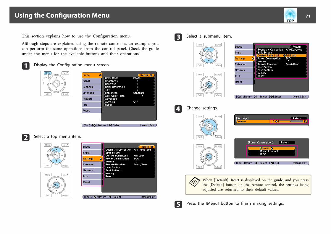
This section explains how to use the Configuration menu.
Although steps are explained using the remote control as an example, youcan perform the same operations from the control panel. Check the guideunder the menu for the available buttons and their operations.
a Display the Configuration menu screen.
b Select a top menu item.
c Select a submenu item.
d Change settings.
aWhen [Default]: Reset is displayed on the guide, and you pressthe [Default] button on the remote control, the settings beingadjusted are returned to their default values.
e Press the [Menu] button to finish making settings.
Using the Configuration Menu 71
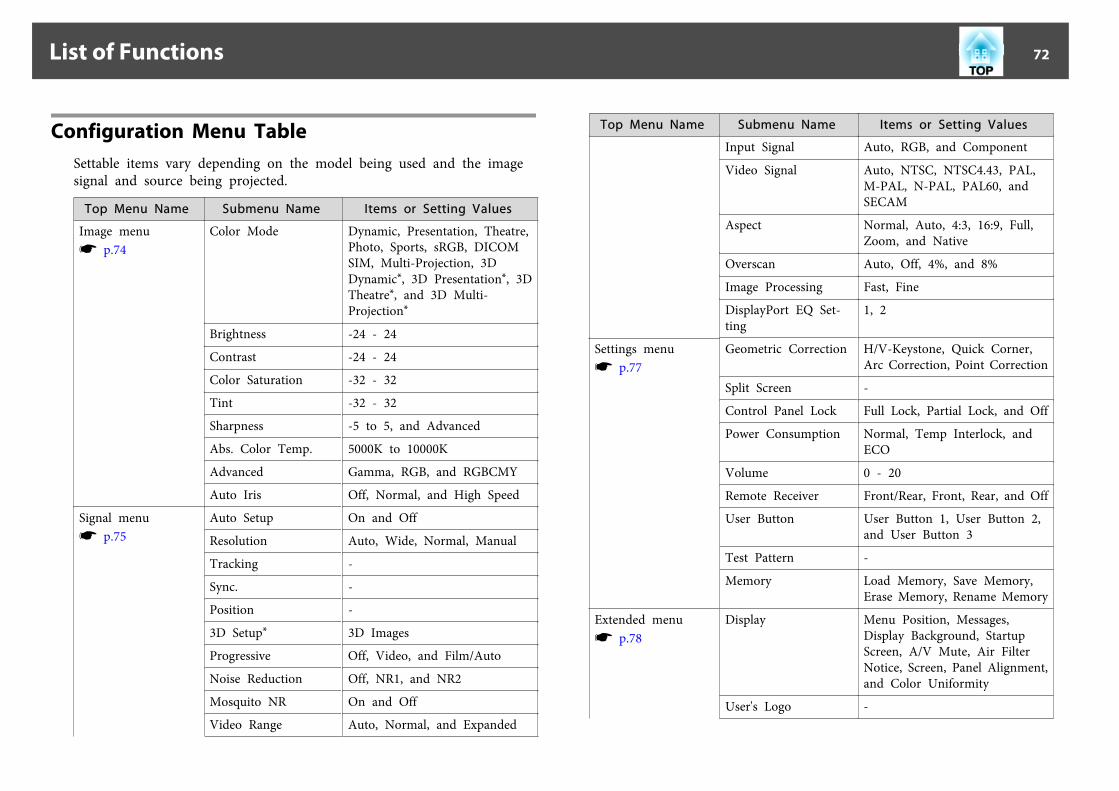
Configuration Menu TableSettable items vary depending on the model being used and the imagesignal and source being projected.
Top Menu Name Submenu Name Items or Setting Values
Image menus p.74
Color Mode Dynamic, Presentation, Theatre,Photo, Sports, sRGB, DICOMSIM, Multi-Projection, 3DDynamic*, 3D Presentation*, 3DTheatre*, and 3D Multi-Projection*
Brightness -24 - 24
Contrast -24 - 24
Color Saturation -32 - 32
Tint -32 - 32
Sharpness -5 to 5, and Advanced
Abs. Color Temp. 5000K to 10000K
Advanced Gamma, RGB, and RGBCMY
Auto Iris Off, Normal, and High Speed
Signal menus p.75
Auto Setup On and Off
Resolution Auto, Wide, Normal, Manual
Tracking -
Sync. -
Position -
3D Setup* 3D Images
Progressive Off, Video, and Film/Auto
Noise Reduction Off, NR1, and NR2
Mosquito NR On and Off
Video Range Auto, Normal, and Expanded
Top Menu Name Submenu Name Items or Setting Values
Input Signal Auto, RGB, and Component
Video Signal Auto, NTSC, NTSC4.43, PAL,M-PAL, N-PAL, PAL60, andSECAM
Aspect Normal, Auto, 4:3, 16:9, Full,Zoom, and Native
Overscan Auto, Off, 4%, and 8%
Image Processing Fast, Fine
DisplayPort EQ Set‐ting
1, 2
Settings menus p.77
Geometric Correction H/V-Keystone, Quick Corner,Arc Correction, Point Correction
Split Screen -
Control Panel Lock Full Lock, Partial Lock, and Off
Power Consumption Normal, Temp Interlock, andECO
Volume 0 - 20
Remote Receiver Front/Rear, Front, Rear, and Off
User Button User Button 1, User Button 2,and User Button 3
Test Pattern -
Memory Load Memory, Save Memory,Erase Memory, Rename Memory
Extended menus p.78
Display Menu Position, Messages,Display Background, StartupScreen, A/V Mute, Air FilterNotice, Screen, Panel Alignment,and Color Uniformity
User's Logo -
List of Functions 72
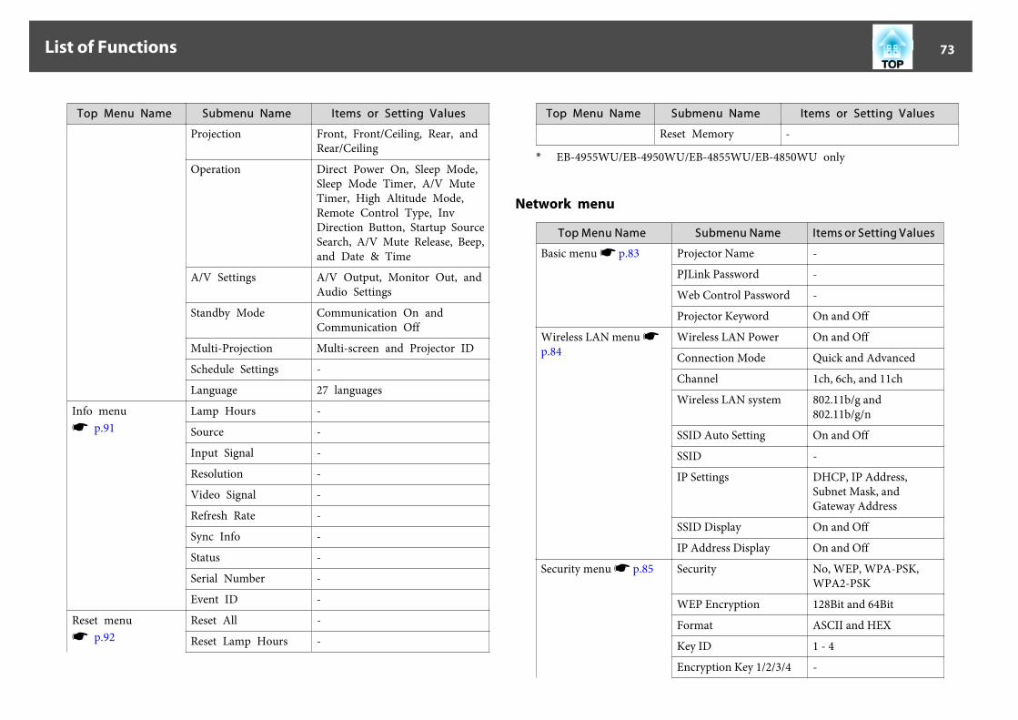
Top Menu Name Submenu Name Items or Setting Values
Projection Front, Front/Ceiling, Rear, andRear/Ceiling
Operation Direct Power On, Sleep Mode,Sleep Mode Timer, A/V MuteTimer, High Altitude Mode,Remote Control Type, InvDirection Button, Startup SourceSearch, A/V Mute Release, Beep,and Date & Time
A/V Settings A/V Output, Monitor Out, andAudio Settings
Standby Mode Communication On andCommunication Off
Multi-Projection Multi-screen and Projector ID
Schedule Settings -
Language 27 languages
Info menus p.91
Lamp Hours -
Source -
Input Signal -
Resolution -
Video Signal -
Refresh Rate -
Sync Info -
Status -
Serial Number -
Event ID -
Reset menus p.92
Reset All -
Reset Lamp Hours -
Top Menu Name Submenu Name Items or Setting Values
Reset Memory -
* EB-4955WU/EB-4950WU/EB-4855WU/EB-4850WU only
Network menu
Top Menu Name Submenu Name Items or Setting Values
Basic menu s p.83 Projector Name -
PJLink Password -
Web Control Password -
Projector Keyword On and Off
Wireless LAN menu sp.84
Wireless LAN Power On and Off
Connection Mode Quick and Advanced
Channel 1ch, 6ch, and 11ch
Wireless LAN system 802.11b/g and802.11b/g/n
SSID Auto Setting On and Off
SSID -
IP Settings DHCP, IP Address,Subnet Mask, andGateway Address
SSID Display On and Off
IP Address Display On and Off
Security menu s p.85 Security No, WEP, WPA-PSK,WPA2-PSK
WEP Encryption 128Bit and 64Bit
Format ASCII and HEX
Key ID 1 - 4
Encryption Key 1/2/3/4 -
List of Functions 73

Top Menu Name Submenu Name Items or Setting Values
Authentication Type Open and Shared
Passphrase -
Wired LAN menu sp.87
IP Settings DHCP, IP Address,Subnet Mask, andGateway Address
IP Address Display On and Off
Mail menu Mail Notification On and Off
SMTP Server -
Port Number -
Address 1 Setting toAddress 3 Setting
Email Address, No Signal,System Error, Lamp Error,High Temp Error, AirFilter Error, ReplaceLamp, High TempWarning, Air FilterWarning, and Air FilterNotice
Others menu SNMP On and Off
Trap IP Address 1 andTrap IP Address 2
-
Priority Gateway Wired LAN and WirelessLAN
AMX Device Discovery On and Off
Crestron RoomView On and Off
Bonjour On and Off
Message Broadcasting On and Off
Image MenuSettable items vary depending on the image signal and source currentlybeing projected. Setting details are saved for each image signal.
s "Automatically Detect Input Signals and Change the Projected Image(Source Search)" p.38
Submenu Function
Color Mode You can select the quality of the image to suit your surroundings.s "Selecting the Projection Quality (Selecting Color Mode)"p.44
Brightness You can adjust the image brightness.
Contrast You can adjust the difference between light and dark in theimages.
Color Saturation (Adjustment is only possible when component video orcomposite video images are being input.)You can adjust the color saturation for the images.
List of Functions 74

Submenu Function
Tint (Adjustment is possible when a component video signal is beinginput. If a composite video signal is input, adjustment is onlypossible when NTSC signals are being input.)You can adjust the image tint.
Sharpness Standard: You can adjust the image sharpness. To make more-detailed settings, select Advanced.Advanced: The following four items can be set.Thin Line Enhancement: If this parameter is set to a positivevalue, details such as hair or fabric patterns will be enhanced.Thick Line Enhancement: If this parameter is set to a positivevalue, the outline, background, and the other main parts of theobjects in the image will be enhanced to show them clearly.Vert. Line Enhancement: If this parameter is set to a positivevalue, vertical lines in the image are enhanced.Horiz. Line Enhancement: If this parameter is set to a positivevalue, horizontal lines in the image are enhanced.
Abs. Color Temp. You can adjust the overall tint of the image. You can adjust tintsin 10 stages from 5000 K to 10000 K. The image is tinted bluewhen a high value is selected and tinted red when a low value isselected.
Advanced You can make adjustments by choosing the following items.Gamma: You can adjust the coloring by selecting one of thegamma correction values, or referring to the projected image or agamma graph.RGB: You can adjust the individual R (red), G (green), and B(blue) components of the offset and gain.RGBCMY: You can adjust the hue, saturation, and brightness ofeach color R (red), G (green), B (blue), C (cyan), M (magenta), Y(yellow) individually.
Submenu Function
Auto Iris (This item can be set only if Color Mode is set to Dynamic,Theatre, 3D Dynamic or 3D Theatre.)Set the tracking delay depending on the light intensity correctionfor changes in brightness in the image. Light intensitycorrections are not performed when this is set to Off.The setting is stored for each Color Mode.
Reset You can reset all adjustment values for the Image menu to theirdefault settings. See the following to return all menu items totheir default settings.s "Reset Menu" p.92
Signal MenuSettable items vary depending on the image signal and source currentlybeing projected. Setting details are saved for each image signal.
List of Functions 75

Submenu Function
Auto Setup (Only available when an analog RGB computer signal isbeing input.)Set to On to automatically adjust Tracking, Sync., andPosition to the optimum state when the input signalchanges.
Resolution (Only available when an analog RGB computer signal isbeing input.)Set to Auto to automatically identify the resolution of theinput signal. If images are not projected correctly when setto Auto, for example if some of the image is missing, set toWide for wide screens, or set to Normal for 4:3 or 5:4screens depending on the connected computer.Manual allows you to specify the resolution. This is idealwhen connected computer is fixed.
Tracking (Only available when an analog RGB computer signal isbeing input.)You can adjust computer images when vertical stripesappear in the images.
Sync. (Only available when an analog RGB computer signal isbeing input.)You can adjust computer images when flickering, fuzziness,or interference appear in the images.
Position You can adjust the display position up, down, left, and rightwhen a part of the image is missing so that the whole imageis projected.
3D Setup* When projecting passive 3D images using two projectors, set3D Images to On.
Progressive Interlaceg (i) signal is converted to Progressiveg (p). (IPconversion)Off: Ideal for images with a large amount of movement.Video: Ideal for general video images.Film/Auto: This is ideal for movie films, computer graphics,and animation.
Submenu Function
Noise Reduction (This cannot be set when Image Processing is set toFast.)Smoothes out the roughness in progressive images. Thereare two modes. Select your favorite setting. It isrecommended that this is set to Off when viewing imagesources in which noise is very low, such as for DVDs.
Mosquito NR (This cannot be set when Image Processing is set toFast.)When a progressive signal is being input, you can reducethe wavy noise that occurs in lines between areas withdramatic changes in colors.
Video Range Select the video range for the input signal from the HDMIport and the DisplayPort. Set to Expanded if you areconcerned about misadjusted black levels or blown outhighlights in the image.
Input Signal You can select an input signal from the Computer port orBNC port.If set to Auto, the input signal is set automaticallyaccording to the connected equipment.If colors do not appear correctly when set to Auto, selectthe appropriate signal according to the connectedequipment.
Video Signal You can select an input signal from the Video port or S-Video port. If set to Auto, video signals are recognizedautomatically. If interference appears in the image or aproblem occurs such as no image is being projected whenset to Auto, select the appropriate signal according to theconnected equipment.
Aspect You can set the aspect ratiog for projected images.s "Changing the Aspect Ratio of the Projected Image "p.45
List of Functions 76
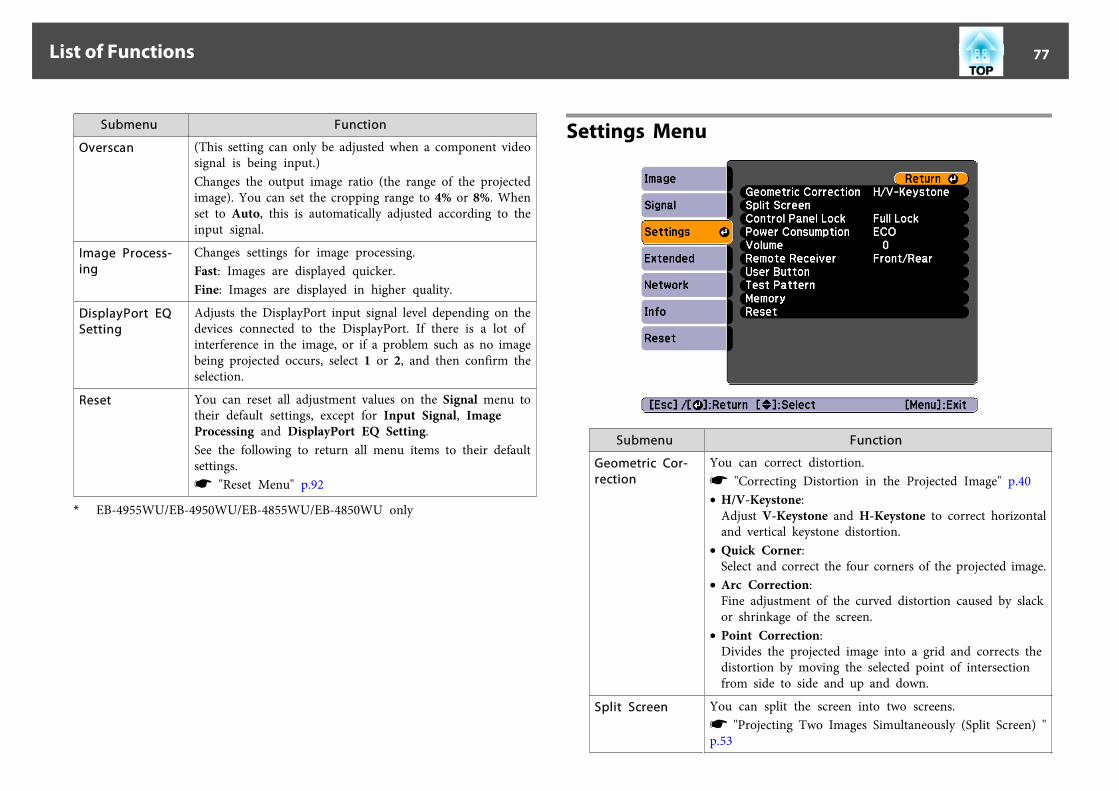
Submenu Function
Overscan (This setting can only be adjusted when a component videosignal is being input.)Changes the output image ratio (the range of the projectedimage). You can set the cropping range to 4% or 8%. Whenset to Auto, this is automatically adjusted according to theinput signal.
Image Process-ing
Changes settings for image processing.Fast: Images are displayed quicker.Fine: Images are displayed in higher quality.
DisplayPort EQSetting
Adjusts the DisplayPort input signal level depending on thedevices connected to the DisplayPort. If there is a lot ofinterference in the image, or if a problem such as no imagebeing projected occurs, select 1 or 2, and then confirm theselection.
Reset You can reset all adjustment values on the Signal menu totheir default settings, except for Input Signal, ImageProcessing and DisplayPort EQ Setting.See the following to return all menu items to their defaultsettings.s "Reset Menu" p.92
* EB-4955WU/EB-4950WU/EB-4855WU/EB-4850WU only
Settings Menu
Submenu Function
Geometric Cor-rection
You can correct distortion.s "Correcting Distortion in the Projected Image" p.40• H/V-Keystone:
Adjust V-Keystone and H-Keystone to correct horizontaland vertical keystone distortion.
• Quick Corner:Select and correct the four corners of the projected image.
• Arc Correction:Fine adjustment of the curved distortion caused by slackor shrinkage of the screen.
• Point Correction:Divides the projected image into a grid and corrects thedistortion by moving the selected point of intersectionfrom side to side and up and down.
Split Screen You can split the screen into two screens.s "Projecting Two Images Simultaneously (Split Screen) "p.53
List of Functions 77
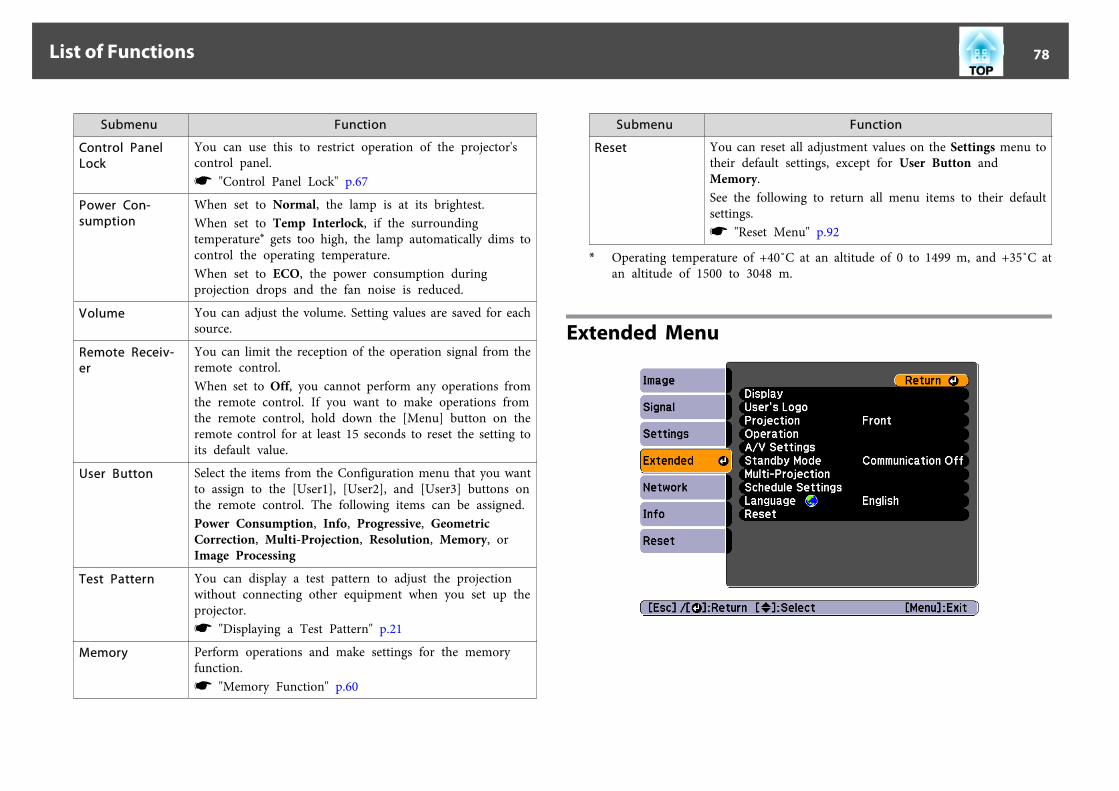
Submenu Function
Control PanelLock
You can use this to restrict operation of the projector'scontrol panel.s "Control Panel Lock" p.67
Power Con-sumption
When set to Normal, the lamp is at its brightest.When set to Temp Interlock, if the surroundingtemperature* gets too high, the lamp automatically dims tocontrol the operating temperature.When set to ECO, the power consumption duringprojection drops and the fan noise is reduced.
Volume You can adjust the volume. Setting values are saved for eachsource.
Remote Receiv-er
You can limit the reception of the operation signal from theremote control.When set to Off, you cannot perform any operations fromthe remote control. If you want to make operations fromthe remote control, hold down the [Menu] button on theremote control for at least 15 seconds to reset the setting toits default value.
User Button Select the items from the Configuration menu that you wantto assign to the [User1], [User2], and [User3] buttons onthe remote control. The following items can be assigned.Power Consumption, Info, Progressive, GeometricCorrection, Multi-Projection, Resolution, Memory, orImage Processing
Test Pattern You can display a test pattern to adjust the projectionwithout connecting other equipment when you set up theprojector.s "Displaying a Test Pattern" p.21
Memory Perform operations and make settings for the memoryfunction.s "Memory Function" p.60
Submenu Function
Reset You can reset all adjustment values on the Settings menu totheir default settings, except for User Button andMemory.See the following to return all menu items to their defaultsettings.s "Reset Menu" p.92
* Operating temperature of +40˚C at an altitude of 0 to 1499 m, and +35˚C atan altitude of 1500 to 3048 m.
Extended Menu
List of Functions 78

Submenu Function
Display You can make settings related to the projector's display.Menu Position: Select the position to display the menu onthe projected screen.Messages: When set to Off, the following items will not bedisplayed.Item names when the Source, Color Mode, or Aspect ischanged, messages when no signal is being input, andwarnings such as High Temp Warning.Display Background*: You can set the screen backgroundto Black, Blue, or Logo when no image signal is available.Startup Screen*: Set to On to display the User's Logo whenprojection starts.A/V Mute*: You can set the screen displayed whenthe [A/V Mute] button is pressed to Black, Blue, orLogo.Air Filter Notice: You can set whether or not (On/Off) toenable Air Filter Notice. When this is set to On and a clogin the air filter is detected, the message is displayed on thescreen.Screen: (This setting is unavailable when projecting imagesfrom a computer over a network.) Set the aspect ratio andposition of the projected screen according to the type ofscreen being used.s "Screen Settings" p.19Panel Alignment: Correct color misalignments (red andblue) in the screen.s "Panel Alignment" p.121Color Uniformity: Adjusts the color tone balance for thewhole screen.s "Color Uniformity" p.122
User's Logo* You can change the user's logo that is displayed as abackground during Display Background, A/V Mute, and soon.s "Saving a User's Logo" p.58
Submenu Function
Projection Select from one of the following projection methodsdepending on how the projector is installed.Front, Front/Ceiling, Rear, and Rear/CeilingYou can change the setting as follows by pressing downthe [A/V Mute] button for about five seconds.FrontWFront/CeilingRearWRear/Ceiling
List of Functions 79

Submenu Function
Operation Direct Power On: Set to On to turn on the projectorsimply by plugging it in.When the power cord is plugged in, note that the projectorturns on automatically in cases such as a power outagebeing restored.Sleep Mode: When set to On, this automatically stopsprojection when no image signal is being input and nooperations are carried out.Sleep Mode Timer: When Sleep Mode is set to On, youcan set the time before the projector automatically turns offwithin a range of 1 to 30 minutes.A/V Mute Timer: When set to On, the projector turns offautomatically after 30 minutes when using A/V mute.High Altitude Mode: Set to On when using the projectorabove an altitude of 1500 m.Remote Control Type: You can select Normal or Simpledepending on the type of remote control.Set this item to Normal to use the remote control providedwith this projector. When Simple is selected, you can usethe remote control provided with other Epson projectors tooperate this projector. This is useful if you want to use aremote control that you are already familiar with to operatethe projector.However, you cannot use the remote control provided withthis projector if this is set to Simple. Make sure that thesetting is correct because, if the projector is mounted on theceiling or somewhere hard to reach, changing it back toNormal may be difficult. Additionally, you cannot use thefunctions that are not equipped with this projector or theremote control which you use.Inv Direction Button: Set this to On when the projector isinstalled on a ceiling.Startup Source Search: Set whether or not (On/Off) toautomatically detect the image signal being input when theprojector is turned on.
Submenu FunctionA/V Mute Release: (This item cannot be set if User's LogoProtection from Password Protection is set to On.s p.65) When set to A/V Mute, you can only release A/Vmute by pressing the [A/V Mute] button (or by sending anA/V mute Off command). When set to Any Button, A/Vmute is released when any operation is performed on theprojector.s "Hiding the Image and Sound Temporarily (A/V Mute)"p.56Beep: When this is set to On, the confirmation buzzerbeeps to notify you that the power turns on or off, orcooling down is finished.Date & Time: Make system time settings for the projector.s "Setting the Time" p.26
List of Functions 80

Submenu Function
A/V Settings A/V Output: (This item can be set only if Standby Mode isset to Communication On) Set this to Always On when theprojector is in standby status and you want to output audioand images to an external device.Monitor Out: Select the image source output to an externalmonitor when the projector is in standby status. When setto Auto, analog RGB signals from the Computer port or theBNC port are output depending on which source wasselected when the projector was turned off.Audio Settings: Perform the following audio relatedsettings.• Audio Output: Select the audio to be output when
projecting images from the Computer port, BNC port,S-Video port or Video port. When set to Auto, audio isoutput from the audio input port corresponding to eachimage input port.s "Connecting Equipment" p.28
• DisplayPort Audio Output: Select the audio source whenprojecting images from the DisplayPort. If you selectDisplayPort, audio for the image is output as it is. If youselect Audio3, audio is output from the Audio3 port.
• HDMI Audio Output: Select the audio source whenprojecting images from the HDMI port. If you selectHDMI, audio for the image is output as it is.If you select Audio3, audio is output from the Audio3port.
Standby Mode If you set Communication On, you can perform thefollowing operations even if the projector is in standbymode.• Monitor and control the projector over a network.• Output audio and images to an external device. (Only
when A/V Output is set to Always On.)
Submenu Function
Multi-Projection Multi-screen: You can adjust the tint and brightness of eachprojected image.s "Correcting" p.50Projector ID: Set the ID from 1 to 9.Off indicates that noID is set.s "ID Settings" p.25
Schedule Set-tings
You can set the projector's schedule so that it performs aspecific operation at a pre-scheduled time.s "Scheduling Function" p.62
Language You can set the language for messages and menus.
Reset You can reset all adjustment values for the Extended menuto their default settings. However, the following items arenot reset.Screen Type, Screen Position, Projection, High AltitudeMode, Remote Control Type, Inv Direction Button,Startup Source Search, A/V Mute Release, A/V Output,Monitor Out, Standby Mode, Multi-screen, Projector ID,and LanguageSee the following to return all menu items to their defaultsettings.s "Reset Menu" p.92
* When User's Logo Protection is set to On in Password Protection, settingsrelated to user's logo cannot be changed. You can make changes after settingUser's Logo Protection to Off.s "Managing Users (Password Protection)" p.65
Network MenuWhen Network Protection is set to On in Password Protection, a messageis displayed and the network settings cannot be changed. Set NetworkProtection to Off and then configure the network.
List of Functions 81

s "Setting Password Protection" p.65
Submenu Function
Net. Info. - Wire-less LAN
Displays the following network setting status information.• Connection Mode• Antenna Level• Projector Name• SSID• DHCP• IP Address• Subnet Mask• Gateway Address• MAC Address• Region Code
Net. Info. - WiredLAN
Displays the following network setting status information.• Projector Name• DHCP• IP Address• Subnet Mask• Gateway Address• MAC Address
Submenu Function
Network Config-uration
The following menus are available for setting Network items.Basic, Wireless LAN, Security, Wired LAN, Mail, Others, andReset
aBy using a Web browser of a computer connected to the projector ona network, you can set functions and control the projector. Thisfunction is called Web Control. You can easily enter text using akeyboard to make settings for Web Control such as Security settings.s "Changing Settings Using a Web Browser (Web Control)"p.127
Notes on operating the Network menu
Selecting from the top menu and sub menus, and changing selected items isthe same as making operations from the Configuration menu.
When done, make sure you go to the Setup complete menu, and select Yes,No, or Cancel. When you select Yes or No, you are returned to theConfiguration menu.
Yes: Saves the settings and exits the Network menu.
No: Does not save the settings and exits the Network menu.
Cancel: Continues displaying the Network menu.
List of Functions 82

Soft keyboard operations
The Network menu contains items that require input of alphanumericsduring setup. In this case, the following software keyboard is displayed. Usethe [ ][ ][ ][ ] buttons to move the cursor to the desired key, andthen press the [ ] button to enter the selected character. Enter figures byholding down the [Num] button on the remote control, and pressing thenumeric buttons. After inputting, press Finish on the keyboard to confirmyour input. Press Cancel on the keyboard to cancel your input.
• Each time the CAPS key is selected and the [ ] button is pressed, itsets and changes between upper case and lower case letters.
• Each time the SYM1/2 key is selected and the [ ] button is pressed, itsets and changes the symbol keys for the section enclosed by the frame.
The following types of character can be entered.
Numbers 0123456789
Letters ABCDEFGHIJKLMNOPQRSTUVWXYZabcdefghijklmnopqrstuvwxyz
Symbols ! # $ % & ' ( ) + - . / < = > ? @ [ ¥ ] ^ _ { | } ~
a• You cannot use colons (:) for Network menu items.• Except for SSID, you cannot use spaces for Network menu items.• The following four characters cannot be entered using the soft
keyboard. Enter these characters using a Web browser.“ * , ;s "Changing Settings Using a Web Browser (Web Control)"p.127
Basic menu
Submenu Function
Projector Name The projector's name is displayed when using the suppliedapplication EasyMP Network Projection.When editing, you can enter up to 16 single-byte alphanumericcharacters.(" * + , / ; < = > ? [ ¥ ] ` | cannot be used.)
List of Functions 83
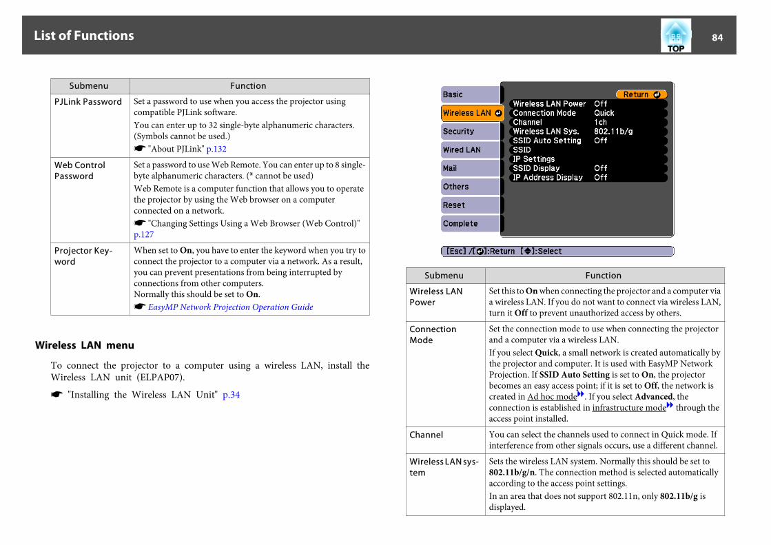
Submenu Function
PJLink Password Set a password to use when you access the projector usingcompatible PJLink software.You can enter up to 32 single-byte alphanumeric characters.(Symbols cannot be used.)s "About PJLink" p.132
Web ControlPassword
Set a password to use Web Remote. You can enter up to 8 single-byte alphanumeric characters. (* cannot be used)Web Remote is a computer function that allows you to operatethe projector by using the Web browser on a computerconnected on a network.s "Changing Settings Using a Web Browser (Web Control)"p.127
Projector Key-word
When set to On, you have to enter the keyword when you try toconnect the projector to a computer via a network. As a result,you can prevent presentations from being interrupted byconnections from other computers.Normally this should be set to On.s EasyMP Network Projection Operation Guide
Wireless LAN menu
To connect the projector to a computer using a wireless LAN, install theWireless LAN unit (ELPAP07).
s "Installing the Wireless LAN Unit" p.34
Submenu Function
Wireless LANPower
Set this to On when connecting the projector and a computer viaa wireless LAN. If you do not want to connect via wireless LAN,turn it Off to prevent unauthorized access by others.
ConnectionMode
Set the connection mode to use when connecting the projectorand a computer via a wireless LAN.If you select Quick, a small network is created automatically bythe projector and computer. It is used with EasyMP NetworkProjection. If SSID Auto Setting is set to On, the projectorbecomes an easy access point; if it is set to Off, the network iscreated in Ad hoc modeg. If you select Advanced, theconnection is established in infrastructure modeg through theaccess point installed.
Channel You can select the channels used to connect in Quick mode. Ifinterference from other signals occurs, use a different channel.
Wireless LAN sys-tem
Sets the wireless LAN system. Normally this should be set to802.11b/g/n. The connection method is selected automaticallyaccording to the access point settings.In an area that does not support 802.11n, only 802.11b/g isdisplayed.
List of Functions 84

Submenu Function
SSID Auto Set-ting
If Connection Mode is set to Quick, when you set this to On, youcan search for the projector more quickly from among multipleprojectors. SSID is set automatically.When connecting to multiple projectors from 1 computer inQuick, set this to Off, and set the same SSID in all the projectorsthat will connect.
SSID Enter an SSID. When an SSID is provided for the wireless LANsystem in which the projector participates, enter the SSID.You can enter up to 32 single-byte alphanumeric characters. (^cannot be used. ) Set SSID to blank or ANY to establish an ANYconnection.
IP Settings DHCP: You can set whether or not (On/Off) to use DHCPg.If this is set to On, you cannot set any more addresses.IP Address: You can input the IP addressg assigned to theprojector.You can enter a number from 0 to 255 in each field of the address.However, the following IP addresses cannot be used. 0.0.0.0,127.x.x.x, 224.0.0.0 to 255.255.255.255 (where x is a number from0 to 255)Subnet Mask: You can input the Subnet Maskg for theprojector. You can enter a number from 0 to 255 in each field ofthe address. However, the following subnet masks cannot beused.0.0.0.0, 255.255.255.255Gateway Address: You can input the IP address for the gatewayfor the projector.You can enter a number from 0 to 255 in each field of the address.However, the following Gateway addressesg cannot be used.0.0.0.0, 127.x.x.x, 224.0.0.0 to 255.255.255.255 (where x is anumber from 0 to 255)
SSID Display To prevent the SSID from being displayed on the LAN Standbyscreen, set this to Off.
IP Address Dis-play
To prevent the IP address from being displayed on the LANStandby screen, set this to Off.
Security menu
When the Wireless LAN unit is installed, it is strongly recommended thatyou set security.
List of Functions 85

Submenu Function
Security You can select a type of security.• When Quick is selected
No: Security is not set.WPA2-PSK (only when SSID Auto Setting is set to On):Communication is performed using WPA2 security. UsesAES method for encryption. When establishing aconnection from a computer to the projector, enter thevalue set in the passphrase.
• When Advanced is selectedNo: Security is not set.WEP: Connects using an encryption key (WEP key).Communication is not possible if the encryption keybetween the access point and the projector does notmatch.WPA-PSK/WPA2-PSK: Connects in WPA personal mode.Encryption method is selected automatically according tothe access point settings. Set a passphrase which is thesame for the access point.
Submenu Function
WEP Encryption Set the encryption method for WEP encryption.128Bit: Uses 128 (104) bit encryption.64Bit: Uses 64 (40) bit encryption.
Format Set the format for the WEP encryption key.ASCII: Input as text.HEX: Input in hexadecimal.
Key ID Select the WEP encryption ID key.
Encryption Key1/Encryption Key2/Encryption Key3/Encryption Key4
Enter the key to be used for WEP encryption. Enter the key insingle-byte characters according to instructions from theadministrator for the network the projector is going to join. Thetype of supported characters and the number of characterschanges depending on the WEP Encryption and Formatsettings.For 128Bit - ASCII: 13 single-byte alphanumeric charactersFor 64Bit - ASCII: 5 single-byte alphanumeric charactersFor 128Bit - HEX: 26 characters using 0 to 9 and A to FFor 64Bit - HEX: 10 characters using 0 to 9 and A to F
AuthenticationType
Sets the WEP authentication type.Open: Uses an open system authentication.Shared: Uses a shared key authentication.
List of Functions 86
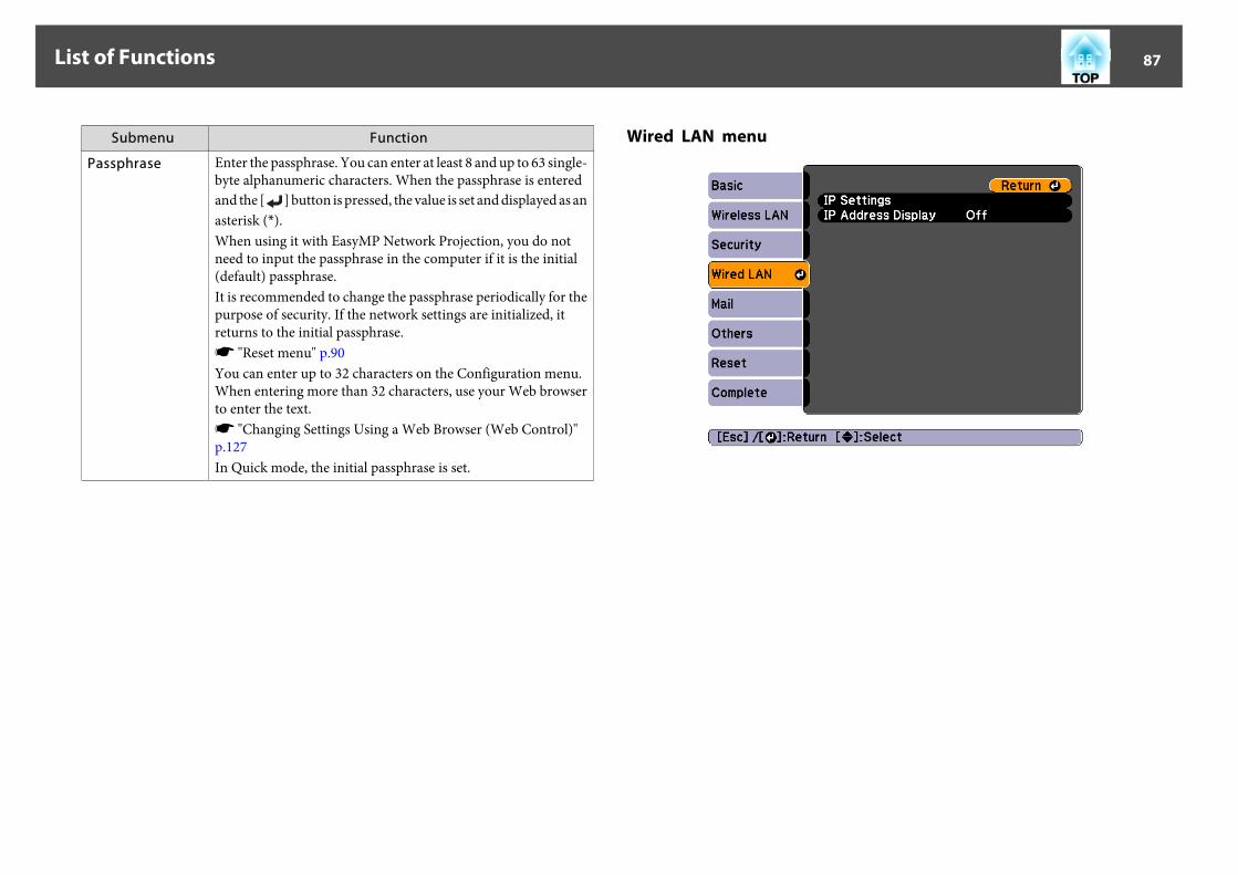
Submenu Function
Passphrase Enter the passphrase. You can enter at least 8 and up to 63 single-byte alphanumeric characters. When the passphrase is enteredand the [ ] button is pressed, the value is set and displayed as anasterisk (*).When using it with EasyMP Network Projection, you do notneed to input the passphrase in the computer if it is the initial(default) passphrase.It is recommended to change the passphrase periodically for thepurpose of security. If the network settings are initialized, itreturns to the initial passphrase.s "Reset menu" p.90You can enter up to 32 characters on the Configuration menu.When entering more than 32 characters, use your Web browserto enter the text.s "Changing Settings Using a Web Browser (Web Control)"p.127In Quick mode, the initial passphrase is set.
Wired LAN menu
List of Functions 87
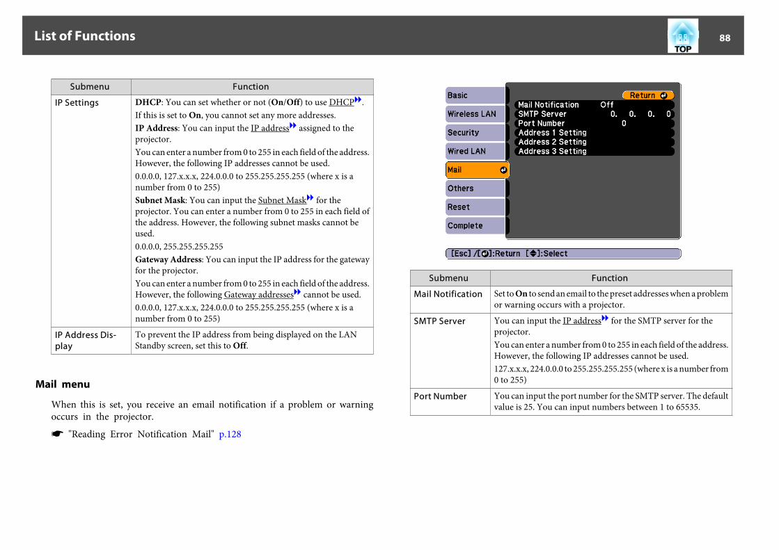
Submenu Function
IP Settings DHCP: You can set whether or not (On/Off) to use DHCPg.If this is set to On, you cannot set any more addresses.IP Address: You can input the IP addressg assigned to theprojector.You can enter a number from 0 to 255 in each field of the address.However, the following IP addresses cannot be used.0.0.0.0, 127.x.x.x, 224.0.0.0 to 255.255.255.255 (where x is anumber from 0 to 255)Subnet Mask: You can input the Subnet Maskg for theprojector. You can enter a number from 0 to 255 in each field ofthe address. However, the following subnet masks cannot beused.0.0.0.0, 255.255.255.255Gateway Address: You can input the IP address for the gatewayfor the projector.You can enter a number from 0 to 255 in each field of the address.However, the following Gateway addressesg cannot be used.0.0.0.0, 127.x.x.x, 224.0.0.0 to 255.255.255.255 (where x is anumber from 0 to 255)
IP Address Dis-play
To prevent the IP address from being displayed on the LANStandby screen, set this to Off.
Mail menu
When this is set, you receive an email notification if a problem or warningoccurs in the projector.
s "Reading Error Notification Mail" p.128
Submenu Function
Mail Notification Set to On to send an email to the preset addresses when a problemor warning occurs with a projector.
SMTP Server You can input the IP addressg for the SMTP server for theprojector.You can enter a number from 0 to 255 in each field of the address.However, the following IP addresses cannot be used.127.x.x.x, 224.0.0.0 to 255.255.255.255 (where x is a number from0 to 255)
Port Number You can input the port number for the SMTP server. The defaultvalue is 25. You can input numbers between 1 to 65535.
List of Functions 88
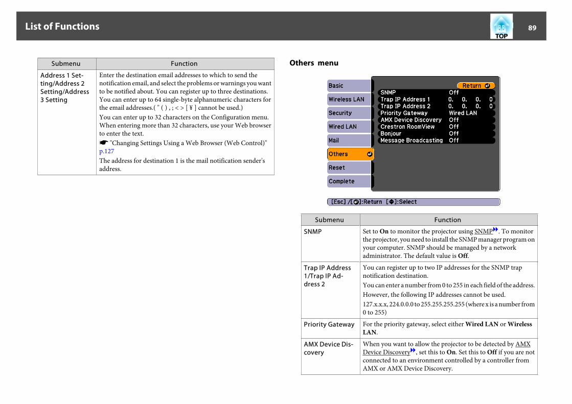
Submenu Function
Address 1 Set-ting/Address 2Setting/Address3 Setting
Enter the destination email addresses to which to send thenotification email, and select the problems or warnings you wantto be notified about. You can register up to three destinations.You can enter up to 64 single-byte alphanumeric characters forthe email addresses.( " ( ) , ; < > [ ¥ ] cannot be used.)You can enter up to 32 characters on the Configuration menu.When entering more than 32 characters, use your Web browserto enter the text.s "Changing Settings Using a Web Browser (Web Control)"p.127The address for destination 1 is the mail notification sender'saddress.
Others menu
Submenu Function
SNMP Set to On to monitor the projector using SNMPg. To monitorthe projector, you need to install the SNMP manager program onyour computer. SNMP should be managed by a networkadministrator. The default value is Off.
Trap IP Address1/Trap IP Ad-dress 2
You can register up to two IP addresses for the SNMP trapnotification destination.You can enter a number from 0 to 255 in each field of the address.However, the following IP addresses cannot be used.127.x.x.x, 224.0.0.0 to 255.255.255.255 (where x is a number from0 to 255)
Priority Gateway For the priority gateway, select either Wired LAN or WirelessLAN.
AMX Device Dis-covery
When you want to allow the projector to be detected by AMXDevice Discoveryg, set this to On. Set this to Off if you are notconnected to an environment controlled by a controller fromAMX or AMX Device Discovery.
List of Functions 89
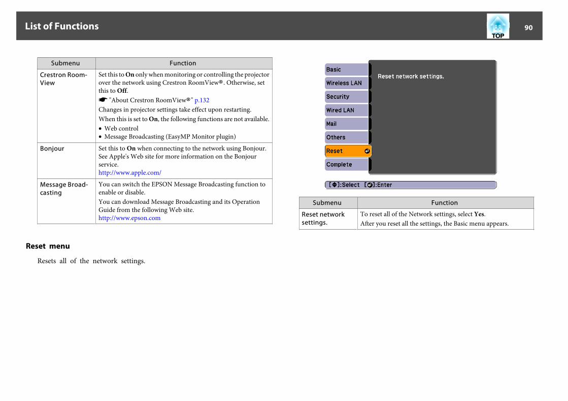
Submenu Function
Crestron Room-View
Set this to On only when monitoring or controlling the projectorover the network using Crestron RoomView®. Otherwise, setthis to Off.s "About Crestron RoomView®" p.132Changes in projector settings take effect upon restarting.When this is set to On, the following functions are not available.• Web control• Message Broadcasting (EasyMP Monitor plugin)
Bonjour Set this to On when connecting to the network using Bonjour.See Apple's Web site for more information on the Bonjourservice.http://www.apple.com/
Message Broad-casting
You can switch the EPSON Message Broadcasting function toenable or disable.You can download Message Broadcasting and its OperationGuide from the following Web site.http://www.epson.com
Reset menu
Resets all of the network settings.
Submenu Function
Reset networksettings.
To reset all of the Network settings, select Yes.After you reset all the settings, the Basic menu appears.
List of Functions 90

Info Menu (Display Only)Lets you check the status of the image signals being projected and the statusof the projector. Items that can be displayed vary depending on the sourcecurrently being projected.
Submenu Function
Lamp Hours You can display the cumulative lamp operating time*.When the lamp replacement time is reached, the charactersare displayed in yellow.
Source You can display the source name for the connectedequipment currently being projected.
Input Signal You can display the content of Input Signal set in theSignal menu according to the source.
Resolution You can display the resolution.
Video Signal You can display the settings for Video Signal in the Signalmenu.
Refresh Rate You can display the refresh rateg.
Sync Info You can display the image signal information.This information may be needed if service is required.
Submenu Function
Status This is information about errors that have occurred on theprojector.This information may be needed if service is required.
Serial Number Displays the projector's serial number.
Event ID Displays the application error log.s "About Event ID" p.110
* The cumulative use time is displayed as "0H" for the first 10 hours. 10 hoursand above is displayed as "10H", "11H", and so on.
List of Functions 91

Reset Menu
Submenu Function
Reset All You can reset all items in the Configuration menu to their defaultsettings.The following items are not reset to their defaults: Input Signal,User's Logo, all items for Network menus, Lamp Hours,Language, Password, Multi-screen, Date & Time, PanelAlignment, and Color Uniformity.
Reset LampHours
Clears the cumulative lamp hours use time. Reset when youreplace the lamp.
Reset Memory The name and settings saved in Save Memory are reset.s "Memory Function" p.60
List of Functions 92

TroubleshootingThis chapter explains how to identify problems and what to do if a problem is found.

If a problem occurs with the projector, the Help screen is displayed to assistyou by pressing the Help button. You can solve problems by answering thequestions.
a Press the [Help] button.
The Help screen is displayed.Remote control
b Select a menu item.
Remote control
c Confirm the selection.
Remote control
Questions and solutions are displayed as shown on the screen below.Press the [Help] button to exit the Help.
aSee the following if the Help function does not provide asolution to the problem.s "Problem Solving" p.95
Using the Help 94
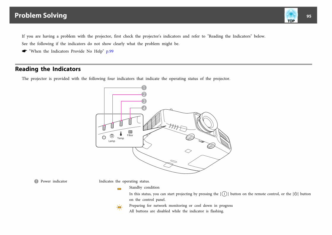
If you are having a problem with the projector, first check the projector's indicators and refer to "Reading the Indicators" below.
See the following if the indicators do not show clearly what the problem might be.
s "When the Indicators Provide No Help" p.99
Reading the IndicatorsThe projector is provided with the following four indicators that indicate the operating status of the projector.
A Power indicator Indicates the operating status.Standby conditionIn this status, you can start projecting by pressing the [ ] button on the remote control, or the [t] buttonon the control panel.Preparing for network monitoring or cool down in progressAll buttons are disabled while the indicator is flashing.
Problem Solving 95

Warming upWarm-up time is about 30 seconds. After warm-up is complete, the indicator stops flashing.The [t] button is disabled during warm-up.Projecting
B Lamp indicator Indicates the projection lamp status.C Temp indicator Indicates the internal temperature status.D Filter indicator Indicates the air filter status.
Refer to the following table to see what the indicators mean and how to remedy problems that they indicate.
If all indicators are off, check that the power cord is connected correctly and that the power is being supplied normally.
Sometimes, when the power cord is unplugged, the [t] indicator remains lit for a short period, but this is not a fault.
: Lit : Flashing : Off : Varies according to the projector status
Status Cause Remedy or Status
Internal Error Stop using the projector, remove the power plug from the electrical outlet, and contact your local dealer or the nearest address provided in theEpson Projector Contact List.s Epson Projector Contact List
Fan ErrorSensor Error
Stop using the projector, remove the power plug from the electrical outlet, and contact your local dealer or the nearest address provided in theEpson Projector Contact List.s Epson Projector Contact List
High Temp Error(Overheating)
The lamp turns off automatically and projection stops. Wait for about five minutes. After about five minutes the projector switches to standbymode, so check the following two points.• Check that the air filter and air exhaust vent are clear, and that the projector is not positioned against a wall.
• If the air filter is clogged, clean or replace it.s "Cleaning the Air Filter" p.112s "Replacing the Air Filter" p.118
If the error continues after checking the points above, stop using the projector, remove the power plug from the electrical outlet, and contactyour local dealer or the nearest address provided in the Epson Projector Contact List.s Epson Projector Contact List
Problem Solving 96

Status Cause Remedy or Status
When using at an altitude of 1500 m or more, set High Altitude Mode to On.s "Extended Menu" p.78
Lamp ErrorLamp Failure
Check the following two points.• Take out the lamp and check if it is cracked.s "Replacing the Lamp" p.115
• Clean the air filter.s "Cleaning the Air Filter" p.112
If the lamp is not cracked: Reinstall the lamp and turn on the power.If the error continues: Replace the lamp with a new one and then turn on the power.If the error continues: Stop using the projector, remove the power plug from the electrical outlet, and contact your local dealer or the nearestaddress provided in the Epson Projector Contact List.s Epson Projector Contact List
If the lamp is cracked: Contact your local dealer or the nearest address provided in the Epson Projector Contact List. (Images cannot beprojected until the lamp is replaced.)s Epson Projector Contact List
When using at an altitude of 1500 m or more, set High Altitude Mode to On.s "Extended Menu" p.78
Auto Iris ErrorPower Err. (Ballast)
Stop using the projector, remove the power plug from the electrical outlet, and contact your local dealer or the nearest address provided in theEpson Projector Contact List.s Epson Projector Contact List
Filter Airflow Error Check the following two points.• Check that the air filter and air exhaust vent are clear, and that the projector is not positioned against a wall.
• If the air filter is clogged, clean or replace it.s "Cleaning the Air Filter" p.112s "Replacing the Air Filter" p.118
If the error continues after checking the points above, stop using the projector, remove the power plug from the electrical outlet, and contactyour local dealer or the nearest address provided in the Epson Projector Contact List.s Epson Projector Contact List
Problem Solving 97

Status Cause Remedy or Status
High Temp Warning (This is not an abnormality. However, if the temperature rises too high again, projection stops automatically.)• Check that the air filter and air exhaust vent are clear, and that the projector is not positioned against a wall.
• If the air filter is clogged, clean or replace it.s "Cleaning the Air Filter" p.112s "Replacing the Air Filter" p.118
Replace Lamp Replace it with a new lamp.s "Replacing the Lamp" p.115If you continue to use the lamp after the replacement period has passed, the possibility that the lamp may explode increases. Replace it with anew lamp as soon as possible.
Low Air Flow Check the following two points.• Check that the air filter and air exhaust vent are clear, and that the projector is not positioned against a wall.
• If the air filter is clogged, clean or replace it.s "Cleaning the Air Filter" p.112s "Replacing the Air Filter" p.118
If the error continues after checking the points above, stop using the projector, remove the power plug from the electrical outlet, and contactyour local dealer or the nearest address provided in the Epson Projector Contact List.s Epson Projector Contact List
Air Filter Notice "Time to clean the air filter. Clean or replace the air filter." is displayed. Clean the air filter.s "Cleaning the Air Filter" p.112The indicators or messages regarding Air Filter Notice are displayed only when Air Filter Notice is set to On from the Configuration menu.s Extended - Display - Air Filter Noticep.78
a• See the following if the projector is not operating properly, even though the indicators are all showing normal.s "When the Indicators Provide No Help" p.99
• If the indicators are in a state not shown in this table, stop using the projector, remove the power plug from the electrical outlet, and contact your local dealer orthe nearest address provided in the Epson Projector Contact List.s Epson Projector Contact List
Problem Solving 98
When the Indicators Provide No HelpIf any of the following problems occur and the indicators do not offer asolution, refer to the pages given for each problem.
Problems Relating to Images
• No images appearProjection does not start, the projection area is completely black,or the projection area is completely blue.
sp.100
• Moving images are not displayedVideos played back on a computer are black or no image isprojected, or the video is not played back on the computer.
sp.100
• Projection stops automatically sp.101
• The message "Not supported" is displayed sp.101
• The message "No Signal" is displayed sp.101
• Images are fuzzy, out of focus, or distorted sp.102
• Interference or distortion appear in images sp.102
• The image is truncated (large) or small, the aspect ratio is notsuitable, or the image has been reversedOnly part of the image is displayed, the height and width ratiosof the image are not correct, or the image may appear reversedfrom top to bottom or left to right.
sp.103
• Image colors are not rightThe whole image appears purplish or greenish, images are black& white, or colors appear dull.
sp.104
• Images appear dark sp.105
Problems when projection starts
• The projector does not turn on sp.105
Other Problems
• No sound can be heard or the sound is faint sp.106
• The remote control does not work sp.107
• Nothing appears on the external monitor sp.108
• I want to change the language for messages and menus sp.108
• Email is not received even if a problem occurs in the projector sp.108
• "The battery that saves your clock settings is running low." isdisplayed
sp.109
• Cannot change settings using a Web browser sp.109
Problem Solving 99

Problems Relating to Images
No images appear
Check Remedy
Did you press the [ ] button on the remote control or the [t]button on the control panel?
Press the [ ] button on the remote control or the [t] button on the control panel to turn on the projector.
Are the indicators switched off? The power cord is not connected correctly or power is not being supplied.Connect the projector's power cord correctly.Check that your electrical outlet or power source is functioning correctly.
Is A/V Mute active? Press the [A/V Mute] button to release A/V Mute.s "Hiding the Image and Sound Temporarily (A/V Mute)" p.56
Are the Configuration menu settings correct? Reset all of the settings.s Reset - Reset All p.92
Is the image to be projected completely black?(Only when projecting computer images)
Some input images, such as screen savers, may be completely black.
Is the image signal format setting correct?(Only when projecting images from a video source)
Change the setting according to the signal for the connected equipment.s Signal - Video Signal p.75
Is Windows Media Center displayed in full screen?(Only during network connection)
When Windows Media Center is displayed at full screen, you cannot project using a network connection. Reduce thescreen size.
Is an application using the Windows DirectX function displayed?(Only during network connection)
Applications using the Windows DirectX function may not display images correctly.
Moving images are not displayed
Check Remedy
Is the computer's image signal being output to the LCD and themonitor?(Only when projecting images from a laptop computer or acomputer with a built-in LCD screen)
Change the image signal from the computer to external output only. Check your computer's documentation, or contactthe computer's manufacturer.
Problem Solving 100

Check Remedy
Are the contents of the moving image you are trying to projectcopyright protected?
The projector may not be able to project copyright protected moving images that are being played back on a computer.For more details, see the user's guide supplied with the player.
Projection stops automatically
Check Remedy
Is Sleep Mode set to On? Press the [ ] button on the remote control or the [t] button on the control panel to turn on the projector. If you do notwant to use Sleep Mode, change the setting to Off.s Extended - Operation - Sleep Mode p.78
Is A/V Mute Timer set to On? Press the [ ] button on the remote control or the [t] button on the control panel to turn on the projector. If you do notwant to use A/V Mute Timer, change the setting to Off.s Extended - Operation - A/V Mute Timer p.78
The message "Not supported" is displayed
Check Remedy
Is the image signal format setting correct?(Only when projecting images from a video source)
Change the setting according to the signal for the connected equipment.s Signal - Video Signal p.75
Do the image signal resolution and the refresh rate correspond to themode?(Only when projecting computer images)
Refer to the computer's documentation for how to change the image signal resolution and the refresh rate output fromthe computer.s "Supported Monitor Displays" p.144
The message "No Signal" is displayed
Check Remedy
Are the cables connected correctly? Check that all the cables required for projection are securely connected.Check that no cables are disconnected and that there are no poor contacts in the cables.
Is the correct port selected? Press the [Search] button or the [Source Search] button to change the image.s "Automatically Detect Input Signals and Change the Projected Image (Source Search)" p.38
Problem Solving 101

Check Remedy
Is the power for the computer or video source turned on? Turn the power on for the equipment.
Are the image signals being output to the projector?(Only when projecting images from a laptop computer or acomputer with a built-in LCD screen)
If the image signals are only being output to the computer's LCD monitor or to the accessory monitor, you need tochange the output to an external destination as well as the computer's own monitor. For some computer models, whenthe image signals are output externally, they no longer appear on the LCD monitor or accessory monitor.If the connection is made while the power of the projector or computer is already turned on, the Fn key (Function key)that changes the computer's image signal to external output may not work. Turn the power for the computer and theprojector off and then back on again.s Computer's documentation
Images are fuzzy, out of focus, or distorted
Check Remedy
Is the focus adjusted correctly? Turn the focus ring to adjust the focus.s "Correcting the Focus" p.24
Is the projector at the correct distance? Is it projecting outside of the recommended projection distance range?Setup within the recommended range.s "Screen Size and Projection Distance" p.138
Has condensation formed on the lens? If the projector is suddenly taken from a cold environment to a warm environment, or if sudden ambient temperaturechanges occur, condensation may form on the surface of the lens, and this may cause the images to appear fuzzy. Set theprojector up in the room about one hour before it is used. If condensation forms on the lens, turn the projector off andwait for the condensation to disappear.
Interference or distortion appear in images
Check Remedy
Is the image signal format setting correct?(Only when projecting images from a video source)
Change the setting according to the signal for the connected equipment.s Signal - Video Signal p.75
Are the cables connected correctly? Check that all the cables required for projection are securely connected.s "Connecting Equipment" p.28
Is an extension cable being used? If an extension cable is used, electrical interference may affect the signals. Use the cables supplied with the projector tocheck if the cables you are using may be causing the problem.
Problem Solving 102

Check Remedy
Is the correct resolution selected?(Only when projecting computer images)
Set the computer so that the signals being output are compatible with the projector.s "Supported Monitor Displays" p.144s Computer's documentation
Are the Sync.g and Trackingg settings adjusted correctly?(Only when projecting computer images)
Press the [Auto] button on the remote control or the [ ] button on the control panel to perform automatic adjustment.If the images are not adjusted correctly even after performing automatic adjustment, you can also make adjustmentsfrom the Configuration menu.s Signal - Tracking, Sync. p.75
Is the Resolution set to anything other than Auto?(Only when projecting on a split screen)
The image may be collapsed if the Resolution on the Configuration menu and the resolution of the projected image arenot the same.If the image is collapsed, set the Resolution to Auto.s Signal - Resolution p.75
The image is truncated (large) or small, the aspect is not suitable, or the image has been reversed
Check Remedy
Have the Screen Type and Screen Position been set correctly? Make the appropriate Screen Type and Screen Position settings for the screen being used.s "Screen Settings" p.19
Is the aspect adjusted correctly? Press [Aspect] button, and then select the aspect according to the input signal.s "Changing the Aspect Ratio of the Projected Image " p.45
Is a wide panel computer image being projected?(Only when projecting computer images)
Change the setting according to the signal for the connected equipment.s Signal - Resolution p.75
Is the image still being enlarged by E-Zoom? Press the [Esc] button on the remote control to cancel E-Zoom.s "Enlarging Part of the Image (E-Zoom)" p.57
Is the image position adjusted correctly? (Only when projecting analog RGB signals input from the Computer port)Press the [Auto] button on the remote control or the [ ] button on the control panel to adjust the position.You can also adjust the position from the Configuration menu.s Signal - Position p.75
Is the computer set for dual display?(Only when projecting computer images)
If dual display is activated in the Display Properties of the computer's Control Panel, only about half of the image on thecomputer screen is projected. To display the entire image on the computer screen, turn off the dual display setting.s Computer video driver documentation
Problem Solving 103

Check Remedy
Is the correct resolution selected?(Only when projecting computer images)
Set the computer so that the signals being output are compatible with the projector.s "Supported Monitor Displays" p.144s Computer's documentation
Is the image direction correct? Make the correct settings in Projection from the Configuration menu.s "Installation Requirements" p.18
Image colors are not right
Check Remedy
Do the input signal settings match the signals from the connecteddevice?
Change the following settings according to the signal for the connected equipment.• When the image is from a device connected to the Computer port or the BNC ports Signal - Input Signal p.75
• When the image is from a device connected to the Video port or the S-Video ports Signal - Video Signal p.75
Is the image brightness adjusted correctly? Adjust the Brightness setting from the Configuration menu.s Image - Brightness p.74
Are the cables connected correctly? Check that all the cables required for projection are securely connected.Check that no cables are disconnected and that there are no poor contacts in the cables.s "Connecting Equipment" p.28
Is the contrastg adjusted correctly? Adjust the Contrast setting from the Configuration menu.s Image - Contrast p.74
Is the color adjustment set correctly? Adjust the Gamma, RGB, or RGBCMY setting from the Configuration menu.s Image - Advanced p.74s "Adjusting the Image" p.48
Are the color saturation and tint adjusted correctly?(Only when projecting images from a video source)
Adjust the Color Saturation and Tint settings from the Configuration menu.s Image - Color Saturation, Tint p.74
Problem Solving 104
Images appear dark
Check Remedy
Is the image brightness set correctly? Check the Brightness and Power Consumption settings from the Configuration menu.s Image - Brightness p.74s Settings - Power Consumption p.77
Is the contrastg adjusted correctly? Adjust the Contrast setting from the Configuration menu.s Image - Contrast p.74
Is it time to replace the lamp? When the lamp is nearly ready for replacement, the images become darker and the color quality becomes poorer. Whenthis happens, replace the lamp with a new lamp.s "Replacing the Lamp" p.115
Has the projector been left unattended without an image signal beinginput?
If no operations are performed on the projector while no image signal is being input, the lamp is automatically dimmedto prevent electricity being wasted. When an image signal is input or an operation is performed on the projector, theprojector returns to the previous brightness setting.
Is Sleep Mode set to On? If no operations are performed on the projector for approximately five minutes while no image signal is being input, thelamp is automatically dimmed to prevent electricity being wasted.
Problems when Projection Starts
The projector does not turn on
Check Remedy
Did you press the [ ] button on the remote control or the [t]button on the control panel?
Press the [ ] button on the remote control or the [t] button on the control panel to turn on the projector.
Are the indicators switched off? The power cord is not connected correctly or power is not being supplied.Disconnect and then reconnect the power cord.Check that your electrical outlet or power source is functioning correctly.
Do the indicators turn on and off when the power cord is touched? There is probably a poor contact in the power cable, or the power cable may be defective. Reinsert the power cable. If thisdoes not solve the problem, stop using the projector, disconnect the power cable from the electrical outlet, and contactyour local dealer or the nearest address provided in the Epson Projector Contact List.s Epson Projector Contact List
Problem Solving 105

Check Remedy
Is the Control Panel Lock set to Full Lock? Press the [ ] button on the remote control. If you do not want to use Control Panel Lock, change the setting toOff.s "Control Panel Lock" p.67
Is the correct setting for the remote receiver selected? Check the Remote Receiver from the Configuration menu.s Settings - Remote Receiver p.77
Was the power cable plugged back in or was the breaker turned onimmediately after Direct Power Off?
When the operation to the left is performed when Direct Power On is set to On, the power may not turn back on. Pressthe [ ] button on the remote control or the [t] button on the control panel to turn on the projector.
Is the [ID] switch on the remote control set to On? When the switch is set to On, you can use the remote control to operate only a projector with a matching ID. Set the [ID]switch to Off.s "Setting the remote control ID" p.25
Are the lamp cover and lamps installed correctly? If the lamp or lamp cover is installed incorrectly, the projector cannot be turned on. Check how it is installed.s "How to replace the lamp" p.115
Other Problems
No sound can be heard or the sound is faint
Check Remedy
Check that the audio/video cable is securely attached to both theprojector and audio source.
Disconnect the cable from the Audio port, and then reconnect the cable.
Is the projector volume set to the minimum? Adjust the volume so that sound can be heard.s Settings - Volumep.77s "Adjusting the Volume" p.39
Is the volume for the computer or from the image source set to theminimum?
Adjust the volume so that sound can be heard.
Is A/V Mute active? Press the [A/V Mute] button to release A/V Mute.s "Hiding the Image and Sound Temporarily (A/V Mute)" p.56
Is the audio cable's specification "No resistance"? When using a commercially available audio cable, make sure it is labeled "No resistance".
Is it connected with an HDMI cable? If no audio is output when connecting via an HDMI cable, set the connected equipment to PCM output.
Problem Solving 106

Check Remedy
Is the correct audio input selected? Check the Audio Settings from the configuration menu.s Extended - A/V Settings - Audio Settings p.78
The remote control does not work
Check Remedy
Is the remote control light-emitting area pointing towards theremote receiver on the projector during operation?
Point the remote control towards the remote receiver.s "Remote control operating range" p.15
Is the remote control too far from the projector? The operating range for the remote control is about 15 m.s "Remote control operating range" p.15
Is direct sunlight or strong light from fluorescent lamps shining ontothe remote receiver?
Set the projector up in a location where strong light does not shine onto the remote receiver.
Is the correct setting for the Remote Receiver selected? Check the Remote Receiver from the Configuration menu.s Settings - Remote Receiver p.77
Are the batteries dead or have the batteries been inserted correctly? Make sure the batteries are inserted correctly or replace the batteries with new ones if necessary.s "Replacing the remote control batteries" p.14
Are the remote control ID and the projector ID matched? Make sure the ID for the projector you want to operate and the ID for the remote control match. To operate all projectorsby remote control regardless of the ID setting, set the [ID] switch on the remote control to Off.s "ID Settings" p.25
Does Remote Control Type match the remote control that you areusing?
Check the Remote Control Type on the configuration menu.s Extended - Operation - Remote Control Type p.78
Is the optional remote control cable connected to the projector'sRemote port?
When the remote control cable is connected, the projector's remote receiver is disabled. When not using the remotecontrol cable set, disconnect it from the Remote port.
Is the remote control button lock set? When the remote control button lock is set, buttons except for those needed for basic remote control operations aredeactivated. Hold down the [Help] button to cancel the remote control button lock.s "Remote control button lock" p.68
Problem Solving 107

Nothing appears on the external monitor
Check Remedy
Are images input from a port other than the Computer port orBNC port?
Only RGB signals from the Computer port or the BNC port can be displayed on an external monitor.
Are you projecting a split screen? Only RGB signals projected on the left screen from the Computer port or the BNC port can be displayed on anexternal monitor.s "Projecting Two Images Simultaneously (Split Screen) " p.53
Is the projector in standby status? Check that Standby Mode, A/V Output, and Monitor Out from the Configuration menu are set correctly.s Extended - Standby Mode p.78s Extended - A/V Settings p.78
I want to change the language for messages and menus
Check Remedy
Change the Language setting. Adjust the Language setting from the Configuration menu.s Extended - Languagep.78
Email is not received even if a problem occurs in the projector
Check Remedy
Is Standby Mode set to Communication On? To use the Mail Notification function when the projector is in standby, set Communication On in Standby Mode fromthe Configuration menu.s Extended - Standby Mode p.78
Did a fatal abnormality occur and the projector come to a suddenstop?
When the projector comes to a sudden stop, email cannot be sent.If the abnormal state continues, contact your local dealer or the nearest address provided in the Epson Projector ContactList.s Epson Projector Contact List
Is power being supplied to the projector? Check that your electrical outlet or power source is functioning correctly.
Is the Mail Notification function set correctly in the Configurationmenu?
An error notification email is sent according to the Mail settings in the Configuration menu. Check if it is set correctly.s "Mail menu" p.88
Problem Solving 108

"The battery that saves your clock settings is running low." is displayed
Check Remedy
The internal power supply that saves your clock settings isrunning low.
Contact your local dealer or the nearest address provided in the Epson Projector Contact List.s Epson Projector Contact List
Cannot change settings using a Web browser
Check Remedy
Are the user ID and password correct? Enter "EPSONWEB" as the user ID. This cannot be changed. Enter the user ID even if the password setting isdisabled.Enter the characters set for the Web Control Password as the password. The default password is "admin".
Problem Solving 109

Check the numbers and then apply the following countermeasures. If you cannot resolve the problem, contact your network administrator, or contact your localdealer or the nearest address provided in the Epson Projector Contact List.
s Epson Projector Contact List
Event ID Cause Remedy
04320435
Failed to startup EasyMP Network Projection. Restart the projector.
0434048104820485
Network communication is unstable. Check the network communication status, and reconnect after waiting for awhile.
0433 Cannot play transferred images. Restart EasyMP Network Projection.
0484 Communication was disconnected from the computer.
04FE EasyMP Network Projection ended unexpectedly. Check the status of network communications. Restart the projector.
04FF A system error occurred in the projector. Restart the projector.
0891 Cannot find an access point with the same SSID. Set the computer, the access point, and the projector to the same SSID.
0892 The WPA/WPA2 authentication type does not match. Check that the wireless LAN security settings are correct.s "Security menu " p.850893 The WEP/TKIP/AES encryption type does not match.
0894 Communication was disconnected because the projector connected to anunauthorized access point.
Contact your network administrator for more information.
0898 Failed to acquire DHCP. Check the DHCP server to see if it is operating correctly and check the LANcable to see if it is connected correctly. If you are not using DHCP, turn off theDHCP setting.s"Network Menu" p.81
0899 Other communication errors If restarting the projector or EasyMP Network Projection does not solve theproblem, contact your local dealer or the nearest address provided in the EpsonProjector Contact List.s Epson Projector Contact List
About Event ID 110

MaintenanceThis chapter provides information on maintenance procedures to ensure the best level of performance from the projector for a long time to come.

You should clean the projector if it becomes dirty or if the quality ofprojected images starts to deteriorate.
CautionWhen cleaning, unplug the power cable from the electric outlet. Otherwise, itcould cause an electric shock.
Cleaning the Projector's SurfaceClean the projector's surface by wiping it gently with a soft cloth.
If the projector is particularly dirty, moisten the cloth with water containinga small amount of neutral detergent, and then firmly wring the cloth drybefore using it to wipe the projector's surface.
AttentionDo not use volatile substances such as wax, alcohol, or thinner to clean theprojector's surface. The quality of the case may change or become discolored.
Cleaning the LensUse a commercially available cloth for cleaning glasses to gently wipe thelens.
WarningDo not use sprays that contain flammable gas to remove dust and lint from thelens. The projector may catch fire due to the high internal temperature of thelamp.
AttentionDo not rub the lens with harsh materials or subject the lens to shocks, as itcan easily become damaged.
Cleaning the Air FilterWhen the following message is displayed and the filter indicator flashesgreen, clean the air filter and the air intake vent.
"Time to clean the air filter. Clean or replace the air filter."
"The projector is overheating. Make sure nothing is blocking the air vent,and clean or replace the air filter."
"The air filter is clogged. Clean or replace the air filter."
Attention• If dust collects on the air filter, it can cause the internal temperature of the
projector to rise, and this can lead to problems with operation and shortenthe optical engine's service life. Clean the air filter immediately when themessage is displayed.
• Do not rinse the air filter in water. Do not use detergents or solvents.• When using a brush for cleaning, use one with long soft bristles, and brush it
lightly. If it is brushed too strongly, dust will be ground into the air filter andcannot be removed.
Cleaning the air filter
The air filter can be replaced even when the projector is suspended from aceiling.
a After you turn off the projector's power and the confirmationbuzzer beeps twice, disconnect the power cable.
Cleaning 112

b Open the air filter cover.
Slide the air filter cover operation knob, and open the air filtercover.
c Remove the air filter.
Grip the tab in the center of the air filter, and pull it straight out.
d With the front (the side with tabs) of the air filter facing down, tapthe air filter four or five times to shake off the dust.
Turn it over and tap the other side in the same way.
AttentionIf the air filter is hit too hard, it may become unusable due todeformities and cracks.
e Remove any dust remaining on the air filter by using a vacuumcleaner from the front side.
Cleaning 113

f Replace the air filter.
Press until it clicks into place.
g Close the air filter cover.
a• If a message is frequently displayed, even after cleaning, it is time to
replace the air filter. Replace it with a new air filter.s "Replacing the Air Filter" p.118
• It is recommended that you clean these parts at least once everythree months. Clean them more often than this if using the projectorin a particularly dusty environment.
• The indicators or messages regarding Air Filter Notice are displayedonly when Air Filter Notice is set to On from the Configurationmenu.s Extended - Display - Air Filter Notice p.78
Cleaning 114

This section explains how to replace the lamp and the air filter.
Replacing the Lamp
Lamp replacement period
It is time to replace the lamp when:
• The following message is displayed."It is time to replace your lamp. Please contact your Epson projectorreseller or visit www.epson.com to purchase."
The message is displayed for 30 seconds.
• The lamp indicator flashes orange.
• The projected image gets darker or starts to deteriorate.
Attention• The lamp replacement message is set to appear after the following time
periods in order to maintain the initial brightness and quality of the projectedimages.When using Power Consumption continually at Normal: About 3900 hoursWhen using Power Consumption continually at ECO: About 4900 hourss Settings - Power Consumption p.77
• If you continue to use the lamp after the replacement period has passed, thepossibility that the lamp may explode increases. When the lamp replacementmessage appears, replace the lamp with a new one as soon as possible, even ifit is still working.
• Do not repeatedly turn off the power and immediately back on. Turning thepower on and off frequently may shorten the lamp's operating life.
• Depending on the characteristics of the lamp and the way it has been used,the lamp may become darker or stop working before the lamp warningmessage appears. You should always have a spare lamp unit ready in case it isneeded.
• We recommend the use of genuine EPSON spare lamps. The use of non-genuine lamps may affect projection quality and safety. Any damage ormalfunction caused by the use of non-genuine lamps may not covered byEpson's warranty.
a• We recommend that you clean the air filter whenever you replace
the lamp.s "Cleaning the Air Filter" p.112
• Replace the air filter if it is discolored or if a message appears evenafter cleaning the air filter.s "Replacing the Air Filter" p.118
How to replace the lamp
The lamp can be replaced even when the projector is suspended from aceiling.
Replacing Consumables 115

Warning• When replacing the lamp because it has stopped illuminating, there is a
possibility that the lamp may be broken. If replacing the lamp of a projectorwhich has been installed on the ceiling, you should always assume that thelamp is cracked, and you should stand to the side of the lamp cover, notunderneath it. Remove the lamp cover gently. Be careful when removing thelamp cover as shards of glass may fall out and could cause an injury. If anyshards of glass get into your eyes or mouth, contact your local physicianimmediately.
• Never disassemble or remodel the lamp. If a modified or disassembled lampis installed in the projector and used, it could cause a fire, electric shock, oran accident.
CautionWait until the lamp has cooled down sufficiently before removing the lampcover. If the lamp is still hot, burns or other injuries may result. It takes aboutone hour after the power has been turned off for the lamp to be cool enough.
a After you turn off the projector's power and the confirmationbuzzer beeps twice, disconnect the power cord.
b Wait until the lamp has cooled down, then remove the projector'slamp cover.
Loosen the Lamp cover fixing screw with the screwdriver suppliedwith the new lamp unit or a cross-head screwdriver, and thenremove the lamp cover. Because there is a string attached to thelamp cover to prevent it from falling, you can replace the lamp evenwhen the projector is installed on a ceiling without the lamp coverfalling down.
c Loosen the two lamp fixing screws.
Replacing Consumables 116
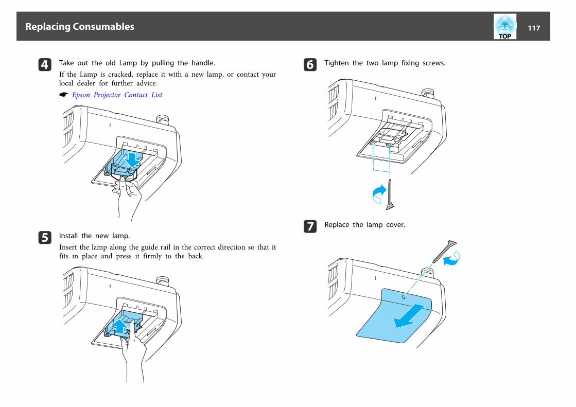
d Take out the old Lamp by pulling the handle.
If the Lamp is cracked, replace it with a new lamp, or contact yourlocal dealer for further advice.s Epson Projector Contact List
e Install the new lamp.
Insert the lamp along the guide rail in the correct direction so that itfits in place and press it firmly to the back.
f Tighten the two lamp fixing screws.
g Replace the lamp cover.
Replacing Consumables 117

Attention• Make sure you install the lamp securely. If the lamp cover is removed, the
power turns off automatically as a safety precaution. If the lamp or the lampcover is not installed correctly, the power does not turn on.
• This product includes a lamp component that contains mercury (Hg). Pleaseconsult your local regulations regarding disposal or recycling. Do not disposeof it with normal waste.
Resetting the lamp hours
The projector records how long the lamp is turned on and a message andindicator notify you when it is time to replace the lamp. After replacing thelamp, make sure you reset the Lamp Hours from the Configuration menu.
s "Reset Menu" p.92
aOnly reset the Lamp Hours after the lamp has been replaced.Otherwise the lamp replacement period is not indicated correctly.
Replacing the Air Filter
Air filter replacement period
If the message is displayed frequently even though the air filter has beencleaned, replace the air filter.
How to replace the air filter
The air filter can be replaced even when the projector is suspended from aceiling.
a After you turn off the projector's power and the confirmationbuzzer beeps twice, disconnect the power cord.
b Open the air filter cover.
Slide the air filter cover operation knob, and open the air filtercover.
c Remove the air filter.
Grip the tab in the center of the air filter, and pull it straight out.
Replacing Consumables 118
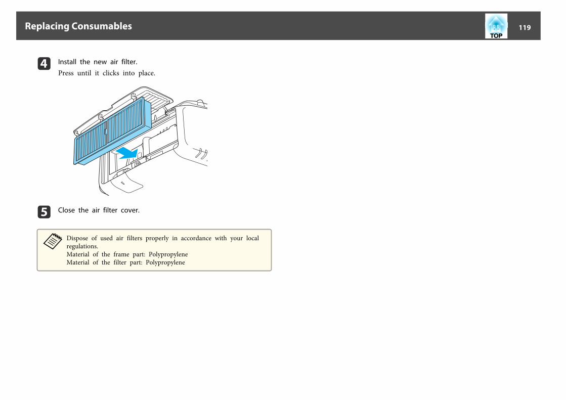
d Install the new air filter.
Press until it clicks into place.
e Close the air filter cover.
aDispose of used air filters properly in accordance with your localregulations.Material of the frame part: PolypropyleneMaterial of the filter part: Polypropylene
Replacing Consumables 119
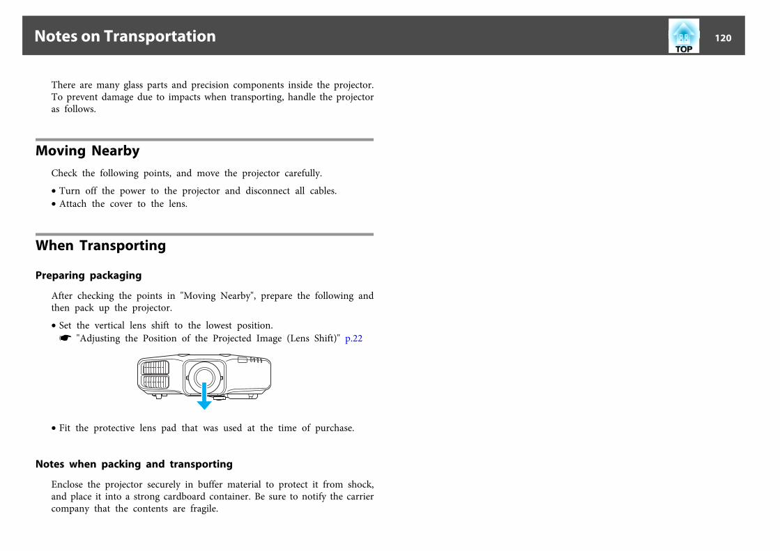
There are many glass parts and precision components inside the projector.To prevent damage due to impacts when transporting, handle the projectoras follows.
Moving NearbyCheck the following points, and move the projector carefully.
• Turn off the power to the projector and disconnect all cables.• Attach the cover to the lens.
When Transporting
Preparing packaging
After checking the points in "Moving Nearby", prepare the following andthen pack up the projector.
• Set the vertical lens shift to the lowest position.s "Adjusting the Position of the Projected Image (Lens Shift)" p.22
• Fit the protective lens pad that was used at the time of purchase.
Notes when packing and transporting
Enclose the projector securely in buffer material to protect it from shock,and place it into a strong cardboard container. Be sure to notify the carriercompany that the contents are fragile.
Notes on Transportation 120

Panel AlignmentAdjusts the pixel color shift for the LCD panel. You can adjust the pixelshorizontally and vertically by 0.25 pixels within a range of ±1 pixel.
a• Image quality may decline after performing LCD alignment.• Images for pixels that extend beyond the edge of the projected
screen are not displayed.
a Press the [Menu] button while projecting.
b Select Display from Extended.
c Select Panel Alignment, and then press the [ ] button.
d Enable Panel Alignment.
(1) Select Panel Alignment, and then press the [ ] button.(2) Select On, and then press the [ ] button.(3) Press the [Esc] button to return to the previous screen.
e Select the color you want to adjust.
(1) Select Select Color, and then press the [ ] button.(2) Select R (red) or B (blue), and then press the [ ] button.(3) Press the [Esc] button to return to the previous screen.
f Select the grid color displayed when making adjustments fromPattern Color.
(1) Select Pattern Color, and then press the [ ] button.
Image Maintenance 121
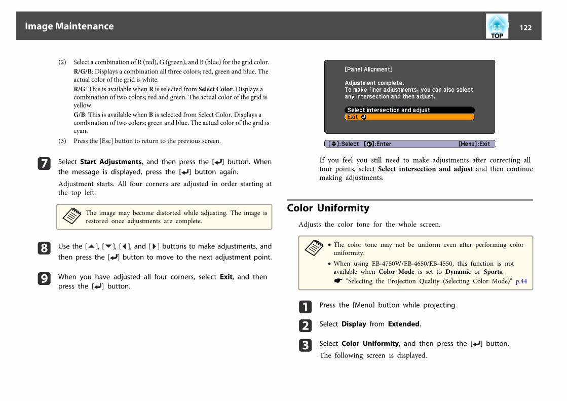
(2) Select a combination of R (red), G (green), and B (blue) for the grid color.R/G/B: Displays a combination all three colors; red, green and blue. Theactual color of the grid is white.R/G: This is available when R is selected from Select Color. Displays acombination of two colors; red and green. The actual color of the grid isyellow.G/B: This is available when B is selected from Select Color. Displays acombination of two colors; green and blue. The actual color of the grid iscyan.
(3) Press the [Esc] button to return to the previous screen.
g Select Start Adjustments, and then press the [ ] button. Whenthe message is displayed, press the [ ] button again.
Adjustment starts. All four corners are adjusted in order starting atthe top left.
aThe image may become distorted while adjusting. The image isrestored once adjustments are complete.
h Use the [ ], [ ], [ ], and [ ] buttons to make adjustments, andthen press the [ ] button to move to the next adjustment point.
i When you have adjusted all four corners, select Exit, and thenpress the [ ] button.
If you feel you still need to make adjustments after correcting allfour points, select Select intersection and adjust and then continuemaking adjustments.
Color UniformityAdjusts the color tone for the whole screen.
a• The color tone may not be uniform even after performing color
uniformity.• When using EB-4750W/EB-4650/EB-4550, this function is not
available when Color Mode is set to Dynamic or Sports.s "Selecting the Projection Quality (Selecting Color Mode)" p.44
a Press the [Menu] button while projecting.
b Select Display from Extended.
c Select Color Uniformity, and then press the [ ] button.
The following screen is displayed.
Image Maintenance 122
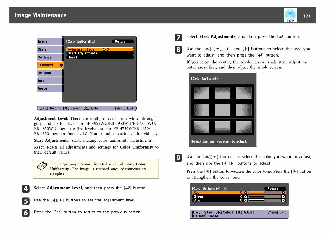
Adjustment Level: There are multiple levels from white, throughgray, and up to black (for EB-4955WU/EB-4950WU/EB-4855WU/EB-4850WU there are five levels, and for EB-4750W/EB-4650/EB-4550 there are four levels). You can adjust each level individually.Start Adjustments: Starts making color uniformity adjustments.Reset: Resets all adjustments and settings for Color Uniformity totheir default values.
aThe image may become distorted while adjusting ColorUniformity. The image is restored once adjustments arecomplete.
d Select Adjustment Level, and then press the [ ] button.
e Use the [ ][ ] buttons to set the adjustment level.
f Press the [Esc] button to return to the previous screen.
g Select Start Adjustments, and then press the [ ] button.
h Use the [ ], [ ], [ ], and [ ] buttons to select the area youwant to adjust, and then press the [ ] button.
If you select the center, the whole screen is adjusted. Adjust theouter areas first, and then adjust the whole screen.
i Use the [ ][ ] buttons to select the color you want to adjust,
and then use the [ ][ ] buttons to adjust.
Press the [ ] button to weaken the color tone. Press the [ ] buttonto strengthen the color tone.
Image Maintenance 123

j Return to step 4 and adjust each level.
k When you are done, press the [Menu] button.
Image Maintenance 124

Appendix
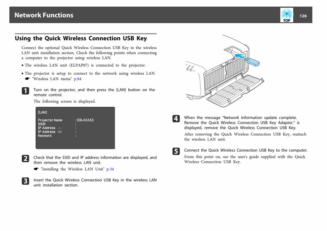
Using the Quick Wireless Connection USB KeyConnect the optional Quick Wireless Connection USB Key to the wirelessLAN unit installation section. Check the following points when connectinga computer to the projector using wireless LAN.
• The wireless LAN unit (ELPAP07) is connected to the projector.
• The projector is setup to connect to the network using wireless LAN.s "Wireless LAN menu" p.84
a Turn on the projector, and then press the [LAN] button on theremote control.
The following screen is displayed.
b Check that the SSID and IP address information are displayed, andthen remove the wireless LAN unit.
s "Installing the Wireless LAN Unit" p.34
c Insert the Quick Wireless Connection USB Key in the wireless LANunit installation section.
d When the message "Network information update complete.Remove the Quick Wireless Connection USB Key Adapter." isdisplayed, remove the Quick Wireless Connection USB Key.
After removing the Quick Wireless Connection USB Key, reattachthe wireless LAN unit.
e Connect the Quick Wireless Connection USB Key to the computer.
From this point on, see the user's guide supplied with the QuickWireless Connection USB Key.
Network Functions 126
About EasyMP MonitorEasyMP Monitor lets you carry out operations such as checking the statusof multiple Epson projectors that are connected to a network at a computermonitor, and controlling the projectors from the computer.
You can download EasyMP Monitor from the following Web site.
http://www.epson.com
About Message Broadcasting
Message Broadcasting is plugin software for EasyMP Monitor.
Message Broadcasting can be used to send a message (JPEG file) to projecton all Epson projectors or specified projectors connected on the network.
The data can be sent manually, or sent automatically using Timer Settingsof EasyMP Monitor.
Download the Message Broadcasting software from the following website.
http://www.epson.com
Changing Settings Using a Web Browser (Web Control)
By using the Web browser of a computer connected to the projector on anetwork, you can make settings and control the projector. This functionallows you to perform setup and control operations remotely. In addition,since you can use the computer's keyboard, entering characters required forthe setup is easier.
Use Internet Explorer 8.0 or later as the Web browser. If using a Mac OSX, use Safari.
aIf you set Standby Mode to Communication On, you can use theWeb browser to make settings and perform control even if theprojector is in standby mode (when the power is off).s Extended - Standby Mode p.78
Projector setup
In the Web browser, you can set items that are usually set in the projector'sConfiguration menu. The settings are reflected in the Configuration menu.
Items in the Configuration menu that cannot be set by the Web browser
• Settings Menu - User Button• Extended Menu - Display - Menu Position, Panel Alignment, Color
Uniformity• Extended Menu - User's Logo• Extended Menu - Operation - High Altitude Mode• Extended Menu - Language• Reset MenuThe settings for items on each menu are the same as the projector'sConfiguration menu.s "Configuration Menu" p.70
Displaying the Web Control screen
Use the following procedure to display the Web Control screen.
Make sure the computer and projector are connected to the network.
Set Connection Mode to Advanced from the Configuration menu.
s Network - Wireless LAN - Connection Mode p.84
Monitoring and Controlling 127

aIf your Web browser is set up to connect via a proxy server, the WebControl screen cannot be displayed. To display Web Control, you needto make settings so that a proxy server is not used for a connection.
a Start the Web browser on the computer.
b Enter the IP address of the projector in the address input box ofthe Web browser, and press the Enter key on the computer'skeyboard.
The Web Control screen is displayed.When Web Control Password is set in the Network menu from theprojector's Configuration menu, the password entry screen isdisplayed.
c The user ID and password entry screen is displayed.
Enter "EPSONWEB" as the user ID.The default password is "admin".
a• Enter the user ID even if the password setting is disabled.
You cannot change the user ID.• You can change the password in the Network menu from the
Configuration menu.s Network - Basic - Web Control Password p.83
Using the Mail Notification Function to Report Problems
When you set Mail Notification, notification messages are sent to the presetemail addresses when a problem or warning occurs with a projector. Thiswill enable the operator to be notified of problems with projectors even atlocations away from the projectors.
s Network - Mail - Mail Notification p.88
a• Up to a maximum of three notification destinations (addresses) can
be registered, and notification messages can be sent to all threedestinations at once.
• If a projector develops a critical problem and suddenly stopsworking, it may not be able to send a message notifying an operatorof the problem.
• If you set Standby Mode to Communication On, you can controlthe projector even if it is in standby mode (when the power isoff).s Extended - Standby Mode p.78
Reading Error Notification Mail
When the Mail Notification function is set to On and a problem or warningoccurs in the projector, the following email will be sent.
Mail sender: Address for Address 1
Subject: EPSON Projector
Line 1: The projector name where the problem has occurred
Line 2: The IP address set for the projector where the problem hasoccurred.
Line 3 and on: Details of the problem
The details of the problem are listed line by line. The main messagecontents are listed below.
• Clean Air Filter (Air Filter Notice)
• Internal error
• Fan related error
• Sensor error
Monitoring and Controlling 128

• Lamp timer failure
• Lamp out
• Internal temperature error
• High-speed cooling in progress
• Lamp replacement notification
• Low Air Flow (Low Air Flow)
• Low Air Flow Error (Filter Airflow Error)
• No-signalNo Signal is input to the projector. Check the connection status or checkthat the power for the signal source is turned on.
• Auto Iris Error
• Power Err. (Ballast)
See the following to deal with problems or warnings.
s "Reading the Indicators" p.95
Management Using SNMPBy setting SNMP to On in the Configuration menu, notification messagesare sent to the specified computer when a problem or warning occurs. Thiswill enable the operator to be notified of problems with projectors even atlocations away from the projectors.
s Network - Others - SNMP p.89
a• SNMP should be managed by a network administrator or someone
who is familiar with the network.• To use the SNMP function to monitor the projector, you need to
install the SNMP manager program on your computer.• Up to two destination IP addresses can be saved.
Displaying the Web Remote ScreenThe Web Remote function allows you to perform projector remote controloperations with a Web browser.
a Display the Web Control screen.
b Click Web Remote.
c The Web Remote screen is displayed.
Monitoring and Controlling 129

A [ ] button
Turns the projector on.B Change input buttonss "Switching to the Target Image by Remote Control" p.39
C [Freeze] buttons "Freezing the Image (Freeze)" p.57
D [A/V Mute] buttons "Hiding the Image and Sound Temporarily (A/V Mute)" p.56
E [Page] buttonss "Remote Control" p.12
F [Volume] buttons
G [Source Search] buttons "Automatically Detect Input Signals and Change the Projected Image(Source Search)" p.38
H [t] buttonTurns the projector off.
ESC/VP21 CommandsYou can control the projector from an external device using ESC/VP21.
Command list
When the power ON command is transmitted to the projector, the powerturns on and it enters warm-up mode. When the projector's power hasturned on, a colon ":" (3Ah) is returned.
When a command is input, the projector executes the command andreturns a ":", and then accepts the next command.
If the command being processed terminates abnormally, an error message isoutput and a ":" is returned.
The main contents are listed below.
Item Command
Power ON/OFF On PWR ON
Off PWR OFF
Signal selection Computer Auto SOURCE 1F
RGB SOURCE 11
Component SOURCE 14
BNC Auto SOURCE BF
RGB SOURCE B1
Component SOURCE B4
HDMI SOURCE 30
Video SOURCE 41
S-Video SOURCE 42
LAN SOURCE 53
DisplayPort SOURCE 70
Monitoring and Controlling 130
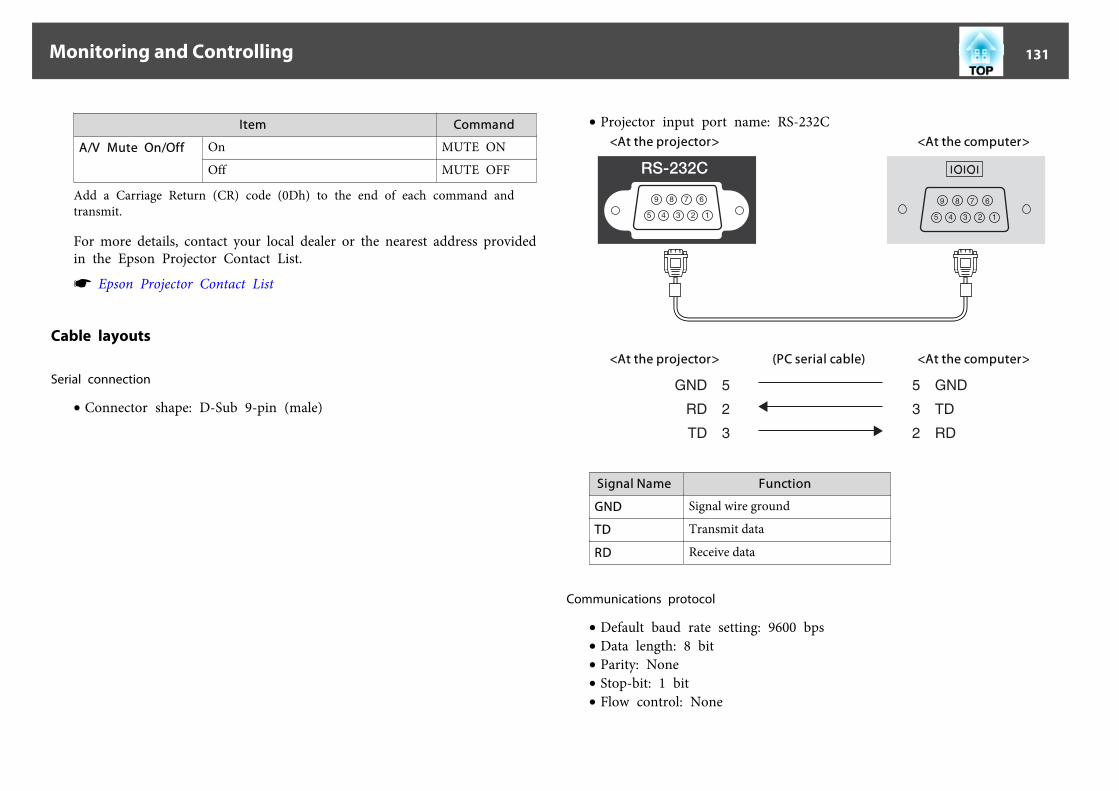
Item Command
A/V Mute On/Off On MUTE ON
Off MUTE OFF
Add a Carriage Return (CR) code (0Dh) to the end of each command andtransmit.
For more details, contact your local dealer or the nearest address providedin the Epson Projector Contact List.
s Epson Projector Contact List
Cable layouts
Serial connection
• Connector shape: D-Sub 9-pin (male)
• Projector input port name: RS-232C<At the projector> <At the computer>
<At the projector> (PC serial cable) <At the computer>
Signal Name Function
GND Signal wire ground
TD Transmit data
RD Receive data
Communications protocol
• Default baud rate setting: 9600 bps• Data length: 8 bit• Parity: None• Stop-bit: 1 bit• Flow control: None
Monitoring and Controlling 131

About PJLinkPJLink Class1 was established by the JBMIA (Japan Business Machine andInformation System Industries Association) as a standard protocol forcontrolling network-compatible projector's as part of their efforts tostandardize projector control protocols.
The projector complies with the PJLink Class1 standard established by theJBMIA.
You need to make network settings before you can use PJLink. See thefollowing for more information on network settings.
s "Network Menu" p.81
It complies with all commands except for the following commands definedby PJLink Class1, and agreement was confirmed by the PJLink standardadaptability verification.
URL:http://pjlink.jbmia.or.jp/english/
• Non-compatible commands
Function PJLink Command
Mute settings Image muting set AVMT 11
Audio muting set AVMT 21
• Input names defined by PJLink and corresponding projector sources
Source PJLink Command
Computer INPT 11
BNC INPT 13
Video INPT 21
S-Video INPT 22
HDMI INPT 32
DisplayPort INPT 35
Source PJLink Command
LAN INPT 52
• Manufacturer name displayed for "Manufacture name information query"EPSON
• Model name displayed for "Product name information query"EPSON 4955/4950EPSON 4855/4850EPSON 4750EPSON 4550EPSON 4650
About Crestron RoomView®Crestron RoomView® is an integrated control system provided byCrestron®. It can be used to monitor and control multiple devicesconnected on a network.
The projector supports the control protocol, and can therefore be used in asystem built with Crestron RoomView®.
Visit the Crestron® Web site for details on Crestron RoomView®. (OnlyEnglish-language displays are supported.)
http://www.crestron.com
The following provides an overview of Crestron RoomView®.
• Remote operation using a Web browserYou can operate a projector from your computer just like using a remotecontrol.
Monitoring and Controlling 132
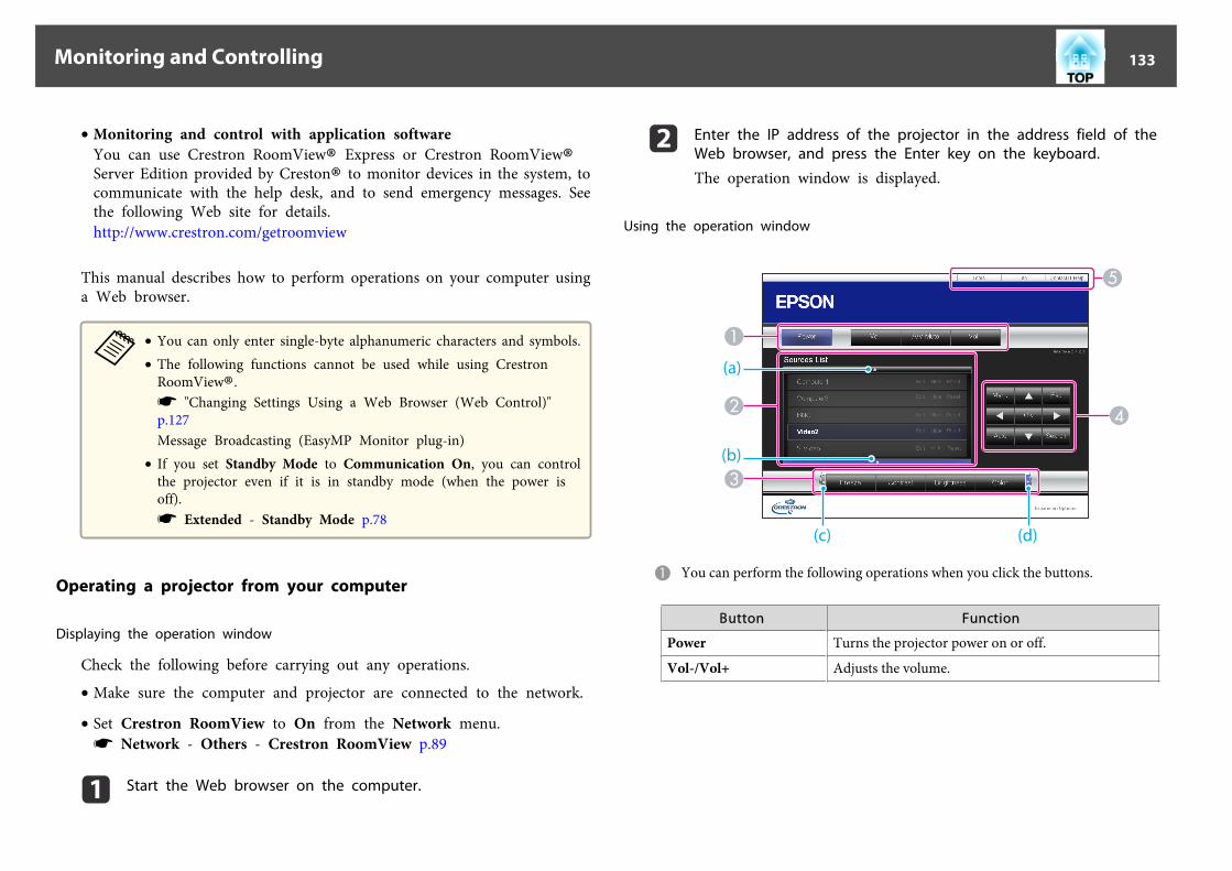
• Monitoring and control with application softwareYou can use Crestron RoomView® Express or Crestron RoomView®Server Edition provided by Creston® to monitor devices in the system, tocommunicate with the help desk, and to send emergency messages. Seethe following Web site for details.http://www.crestron.com/getroomview
This manual describes how to perform operations on your computer usinga Web browser.
a• You can only enter single-byte alphanumeric characters and symbols.• The following functions cannot be used while using Crestron
RoomView®.s "Changing Settings Using a Web Browser (Web Control)"p.127Message Broadcasting (EasyMP Monitor plug-in)
• If you set Standby Mode to Communication On, you can controlthe projector even if it is in standby mode (when the power isoff).s Extended - Standby Mode p.78
Operating a projector from your computer
Displaying the operation window
Check the following before carrying out any operations.
• Make sure the computer and projector are connected to the network.
• Set Crestron RoomView to On from the Network menu.s Network - Others - Crestron RoomView p.89
a Start the Web browser on the computer.
b Enter the IP address of the projector in the address field of theWeb browser, and press the Enter key on the keyboard.
The operation window is displayed.
Using the operation window
A You can perform the following operations when you click the buttons.
Button Function
Power Turns the projector power on or off.
Vol-/Vol+ Adjusts the volume.
Monitoring and Controlling 133

Button Function
A/V Mute Turns the video and audio on or off.s "Hiding the Image and Sound Temporarily (A/VMute)" p.56
B Switch to the image from the selected input source. To display input sources thatare not shown in Source List, click (a) or (b) to scroll up or down. The currentvideo signal input source is displayed in blue.You can change the source name if necessary.
C You can perform the following operations when you click the buttons. To displaybuttons that are not shown in Source List, click (c) or (d) to scroll left or right.
Button Function
Freeze Images are paused or unpaused.s "Freezing the Image (Freeze)" p.57
Contrast Adjusts the difference between light and shade in theimages.
Brightness Adjusts the image brightness.
Color Adjusts the color saturation for the images.
Sharpness Adjusts the image sharpness.
Zoom Click the [z] button to enlarge the image withoutchanging the projection size. Click the [x] button toreduce an image that was enlarged with the [z] button.Click the [ ], [ ], [ ], or [ ] buttons to change theposition of an enlarged image.s "Enlarging Part of the Image (E-Zoom)" p.57
D The [ ], [ ], [ ], and [ ] buttons perform the same operations as the [ ],[ ], [ ], and [ ] buttons on the remote control. You can perform thefollowing operations when you click the other buttons.
Button Function
OK Performs the same operation as the [ ] button on theremote control.s "Remote Control" p.12
Menu Displays and closes the Configuration menu.
Auto If clicked while projecting analog RGB signals from theComputer port, you can automatically optimizeTracking, Sync., and Position.
Search Changes to the next input source that is sending animage.s "Automatically Detect Input Signals and Change theProjected Image (Source Search)" p.38
Esc Performs the same operation as the [Esc] button on theremote control.s "Remote Control" p.12
E You can perform the following operations when you click the tabs.
Tab Function
Contact IT Help Displays the Help Desk window. Used to send messagesto, and receive messages from, the administrator usingCrestron RoomView® Express.
Info Displays information on the projector that is currentlyconnected.
Tools Changes settings in the projector that is currentlyconnected. See the next section.
Using the tools window
The following window is displayed when you click the Tools tab on theoperation window. You can use this window to change settings in theprojector that is currently connected.
Monitoring and Controlling 134

A Crestron ControlMake settings for Crestron® central controllers.
B ProjectorThe following items can be set.
Item Function
Projector Name Enter a name to differentiate the projector that iscurrently connected from other projectors on thenetwork. (The name can contain up to 15 single-bytealphanumeric characters.)
Location Enter an installation location name for the projectorthat is currently connected on the network. (The namecan contain up to 32 single-byte alphanumericcharacters and symbols.)
Assigned To Enter a user name for the projector. (The name cancontain up to 32 single-byte alphanumeric charactersand symbols.)
Item Function
DHCP Select the Enabled check box to use DHCP. You cannotenter an IP address if DHCP is enabled.
IP Address Enter the IP address to assign to the currently connectedprojector.
Subnet Mask Enter a subnet mask for the currently connectedprojector.
Default Gateway Enter the gateway address for the currently connectedprojector.
Send Click this button to confirm the changes made to theProjector.
C Admin PasswordSelect the Enabled check box to require a password to open the Tools window.The following items can be set.
Item Function
New Password Enter the new password when changing the password toopen the Tools window. (The name can contain up to 26single-byte alphanumeric characters.)
Confirm Enter the same password as you entered in NewPassword. If the passwords are not the same, an error isdisplayed.
Send Click this button to confirm the changes made to theAdmin Password.
D User PasswordSelect the Enabled check box to require a password to open the operation windowon the computer.The following items can be set.
Monitoring and Controlling 135

Item Function
New Password Enter the new password when changing the password toopen the operation window. (The name can contain upto 26 single-byte alphanumeric characters.)
Confirm Enter the same password as you entered in NewPassword. If the passwords are not the same, an error isdisplayed.
Send Click this button to confirm the changes made to theUser Password.
Monitoring and Controlling 136

The following optional accessories and consumables are available. Pleasepurchase these products as and when needed. The following list of optionalaccessories and consumables is current as of: April 2013. Details ofaccessories are subject to change without notice and availability may varydepending on the country of purchase.
Optional Accessories
Computer cable ELPKC02(1.8 m - for mini D-Sub15-pin/mini D-Sub 15pin)This is the same as the computer cable supplied with the projector.
Computer cable ELPKC09(3 m - for mini D-Sub15-pin/mini D-Sub 15pin)Computer cable ELPKC10(20 m - for mini D-Sub15-pin/mini D-Sub 15pin)Use one of these longer cables if the computer cable supplied with the projectoris too short.
Component video cable ELPKC19(3 m - for mini D-Sub 15-pin/RCA male^3)Use to connect a component videog source.
Remote control cable set ELPKC28(10 m 2 piece set)Use this to guarantee operation from the remote control from a distance.
Wireless mouse receiver ELPST16Use this to use the projector's remote control to control the mouse pointer onthe computer or to page up and down.
Wireless LAN unit ELPAP07Use when connecting the projector to a computer wirelessly and projecting.
Quick Wireless Connection USB Key ELPAP09Use when you want to quickly establish one-to-one connection between theprojector and a computer with Windows installed.
Polarizer ELPPL01Attach to this projector when stacking two projectors and projecting 3D images.(EB-4955WU/EB-4950WU/EB-4855WU/EB-4850WU only)
Passive 3D Glasses (standard five piece set) ELPGS02APassive 3D Glasses (five piece set for children) ELPGS02BPassive polarized 3D glasses. Use these when viewing 3D images with theprojectors.(EB-4955WU/EB-4950WU/EB-4855WU/EB-4850WU only)
Document Camera ELPDC11Use when projecting images such as books, OHP documents, or slides.
Ceiling pipe (450 mm)* ELPFP13Ceiling pipe (700 mm)* ELPFP14Use when installing the projector on a high ceiling.
Ceiling mount* ELPMB22Use when installing the projector on a ceiling.
Slim Ceiling Mount* ELPMB30Clearly shows the ceiling mount joints.
* Special expertise is required to suspend the projector from a ceiling. Contactyour local dealer or the nearest address provided in the Epson ProjectorContact List.
s Epson Projector Contact List
Consumables
Lamp unit ELPLP77Use as a replacement for used lamps.
Air filter ELPAF45Use as a replacement for used air filters.
Optional Accessories and Consumables 137

Projection Distance (For EB-4955WU/EB-4950WU/EB-4855WU/EB-4850WU)
A Projection distanceB is the distance from the center of the lens to the base of the screen. This
changes depending on the setting for vertical lens shift.C Center of lens
Unit: cm
4:3 Screen SizeA B
Minimum (Wide) toMaximum (Tele)
Vertical Lens ShiftTop to Bottom
50" 102x76 154 - 280 0 - +76
60" 122x91 185 - 337 0 - +91
4:3 Screen SizeA B
Minimum (Wide) toMaximum (Tele)
Vertical Lens ShiftTop to Bottom
80" 163x122 249 - 450 0 - +122
100" 203x152 312 - 564 0 - +152
120" 244x183 376 - 677 0 - +183
150" 305x229 471 - 848 0 - +229
200" 406x305 630 - 1132 0 - +305
250" 508x381 788 - 1415 0 - +381
Unit: cm
16:9 Screen SizeA B
Minimum (Wide) toMaximum (Tele)
Vertical Lens ShiftTop to Bottom
50" 111x62 139 - 254 -3 - +66
60" 133x75 168 - 305 -4 - +79
80" 177x100 226 - 408 -6 - +105
100" 221x125 283 - 511 -7 - +131
120" 266x149 341 - 615 -8 - +153
150" 332x187 427 - 769 -10 - +197
200" 443x249 571 - 1027 -14 - +263
250" 553x311 715 - 1285 -17 - +329
290" 642x361 830 - 1491 -20 - +381
Unit: cm
16:10 Screen SizeA B
Minimum (Wide) toMaximum (Tele)
Vertical Lens ShiftTop to Bottom
50" 108x67 135 - 247 0 - +67
Screen Size and Projection Distance 138

16:10 Screen SizeA B
Minimum (Wide) toMaximum (Tele)
Vertical Lens ShiftTop to Bottom
60" 130x81 163 - 297 0 - +81
80" 172x108 219 - 397 0 - +108
100" 215x135 275 - 498 0 - +135
120" 258x162 331 - 598 0 - +162
150" 323x202 416 - 748 0 - +202
200" 431x269 556 - 999 0 - +269
250" 538x337 696 - 1250 0 - +337
300" 646x404 836 - 1501 0 - +404
Screen Size and Projection Distance 139

Projection Distance (For EB-4750W)
A Projection distanceB is the distance from the center of the lens to the base of the screen. This
changes depending on the setting for vertical lens shift.C Center of lens
Unit: cm
4:3 Screen SizeA B
Minimum (Wide) toMaximum (Tele)
Vertical Lens ShiftTop to Bottom
30" 61x46 90 - 187 -9 - +55
50" 102x76 153 - 314 -16 - +92
60" 122x91 185 - 378 -19 - +110
4:3 Screen SizeA B
Minimum (Wide) toMaximum (Tele)
Vertical Lens ShiftTop to Bottom
80" 163x122 248 - 506 -25 - +147
100" 203x152 311 - 633 -31 - +184
120" 244x183 374 - 761 -38 - +221
150" 305x229 469 - 952 -47 - +276
200" 406x305 627 - 1271 -63 - +368
250" 508x381 785 - 1590 -79 - +460
Unit: cm
16:9 Screen SizeA B
Minimum (Wide) toMaximum (Tele)
Vertical Lens ShiftTop to Bottom
30" 66x37 82 - 169 -11 - +48
50" 111x62 139 - 285 -18 - +80
60" 133x75 168 - 343 -21 - +96
80" 177x100 225 - 459 -28 - +128
100" 221x125 282 - 574 -35 - +160
120" 266x149 340 - 690 -43 - +192
150" 332x187 426 - 864 -53 - +240
200" 443x249 569 - 1153 -71 - +320
250" 553x311 712 - 1443 -89 - +400
Unit: cm
16:10 Screen SizeA B
Minimum (Wide) toMaximum (Tele)
Vertical Lens ShiftTop to Bottom
30" 65x40 79 - 165 -8 - +49
Screen Size and Projection Distance 140

16:10 Screen SizeA B
Minimum (Wide) toMaximum (Tele)
Vertical Lens ShiftTop to Bottom
50" 108x67 135 - 277 -14 - +81
60" 130x81 163 - 334 -17 - +97
80" 172x108 219 - 446 -22 - +130
100" 215x135 274 - 559 -28 - +162
120" 258x162 330 - 671 -33 - +195
150" 323x202 414 - 840 -42 - +244
200" 431x269 553 - 1122 -56 - +325
250" 538x337 693 - 1404 -69 - +406
300" 646x404 832 - 1685 -83 - +487
Screen Size and Projection Distance 141

Projection Distance (For EB-4650/EB-4550)
A Projection distanceB is the distance from the center of the lens to the base of the screen. This
changes depending on the setting for vertical lens shift.C Center of lens
Unit: cm
4:3 Screen SizeA B
Minimum (Wide) toMaximum (Tele)
Vertical Lens ShiftTop to Bottom
30" 61x46 74 - 155 -4 - +50
50" 102x76 127 - 261 -7 - +83
60" 122x91 153 - 315 -8 - +100
4:3 Screen SizeA B
Minimum (Wide) toMaximum (Tele)
Vertical Lens ShiftTop to Bottom
80" 163x122 206 - 421 -11 - +133
100" 203x152 258 - 527 -13 - +166
120" 244x183 311 - 633 -16 - +199
150" 305x229 390 - 793 -20 - +249
200" 406x305 521 - 1059 -27 - +332
250" 508x381 652 - 1324 -34 - +415
300" 610x457 784 - 1590 -40 - +498
Unit: cm
16:9 Screen SizeA B
Minimum (Wide) toMaximum (Tele)
Vertical Lens ShiftTop to Bottom
30" 66x37 82 - 169 -11 - +48
50" 111x62 139 - 285 -18 - +80
60" 133x75 167 - 343 -21 - +96
80" 177x100 225 - 459 -28 - +128
100" 221x125 282 - 575 -35 - +160
120" 266x149 339 - 691 -43 - +192
150" 332x187 425 - 864 -53 - +240
200" 443x249 568 - 1154 -71 - +320
250" 553x311 711 - 1443 -89 - +400
Screen Size and Projection Distance 142

Unit: cm
16:10 Screen SizeA B
Minimum (Wide) toMaximum (Tele)
Vertical Lens ShiftTop to Bottom
30" 65x40 79 - 165 -8 - +49
50" 108x67 135 - 277 -14 - +81
60" 130x81 163 - 334 -17 - +97
80" 172x108 218 - 446 -22 - +130
100" 215x135 274 - 559 -28 - +162
120" 258x162 330 - 672 -33 - +195
150" 323x202 413 - 841 -42 - +244
200" 431x269 553 - 1122 -56 - +325
250" 538x337 692 - 1404 -69 - +406
Screen Size and Projection Distance 143

Supported Resolutions
Computer signals (analog RGB)
Signal Refresh Rate (Hz) Resolution (Dots)
VGA 60/72/75/85 640x480
SVGA 56/60/72/75/85 800x600
XGA 60/70/75/85 1024x768
WXGA 60 1280x768
60 1366x768
60/75/85 1280x800
WXGA+ 60/75/85 1440x900
WXGA++ 60 1600x900
SXGA 70/75/85 1152x864
60/75/85 1280x1024
60/75/85 1280x960
SXGA+ 60/75 1400x1050
WSXGA+*1 60 1680x1050
UXGA 60 1600x1200
WUXGA*2 60 1920x1200
MAC13" 67 640x480
MAC16" 75 832x624
MAC19" 75 1024x768
59 1024x768
Signal Refresh Rate (Hz) Resolution (Dots)
MAC21" 75 1152x870
*1 Only compatible when Wide is selected as the Resolution from theConfiguration menu. (This is not available for EB-4650/EB-4550.)
*2 EB-4955WU/EB-4950WU/EB-4855WU/EB-4850WU only. Only compatiblewhen VESA CVT-RB (Reduced Blanking) signal is input.
Even when signals other than those mentioned above are input, it is likely that theimage can be projected. However, not all functions may be supported.
Component Video
Signal Refresh Rate (Hz) Resolution (Dots)
SDTV (480i) 60 720x480
SDTV (576i) 50 720x576
SDTV (480p) 60 720x480
SDTV (576p) 50 720x576
HDTV (720p) 50/60 1280x720
HDTV (1080i) 50/60 1920x1080
HDTV (1080p)* 50/60 1920x1080
* EB-4955WU/EB-4950WU/EB-4855WU/EB-4850WU only
Composite video
Signal Refresh Rate (Hz) Resolution (Dots)
TV (NTSC) 60 720x480
TV (SECAM) 50 720x576
TV (PAL) 50/60 720x576
Supported Monitor Displays 144

Input signal from the HDMI port and DisplayPort (EB-4955WU/EB-4950WU/EB-4855WU/EB-4850WU/EB-4750W)
Signal Refresh Rate (Hz) Resolution (Dots)
VGA 60 640x480
SVGA 60 800x600
XGA 60 1024x768
WXGA 60 1280x800
60 1280x768*1
60 1366x768
WXGA+ 60 1440x900
WXGA++ 60 1600x900
WSXGA+ 60 1680x1050
SXGA60 1280x960
60 1280x1024
SXGA+ 60 1400x1050
UXGA 60 1600x1200
WUXGA*2 60 1920x1200
SDTV(480i*3/480p)
60 720x480
SDTV(576i*3/576p)
50 720x576
HDTV (720p) 50/60 1280x720
HDTV (1080i) 50/60 1920x1080
HDTV (1080p) 24*3/30*3/50/60 1920x1080
*1 DisplayPort input only*2 EB-4955WU/EB-4950WU/EB-4855WU/EB-4850WU only. Only compatible
when VESA CVT-RB (Reduced Blanking) signal is input.*3 HDMI input only
Input signal from the HDMI port and DisplayPort (EB-4650/EB-4550)
Signal Refresh Rate (Hz) Resolution (Dots)
VGA 60 640x480
SVGA 60 800x600
XGA 60 1024x768
WXGA 60 1280x800
60 1280x768*1
60 1366x768
WXGA+ 60 1440x900
WXGA++ 60 1600x900
SXGA60 1280x960
60 1280x1024
SXGA+ 60 1400x1050
UXGA 60 1600x1200
SDTV(480i*2/480p)
60 720x480
SDTV(576i*2/576p)
50 720x576
HDTV (720p) 50/60 1280x720
HDTV (1080i) 50/60 1920x1080
HDTV (1080p) 24*2/30*2/50/60 1920x1080
*1 DisplayPort input only*2 HDMI input only
Supported Monitor Displays 145

Projector General Specifications
Product name EB-4955WU EB-4950WU EB-4855WU EB-4850WU EB-4750W EB-4650 EB-4550
Dimensions 472 (W) x 134 (H) x 320 (D) mm (not including raised section)
LCD panel size 0.76" Wide 0.59" Wide 0.63"
Display method Polysilicon TFT active matrix
Resolution 2,304,000 pixelsWUXGA (1920 (W) x 1200 (H) dots) x 3
1,024,000 pixelsWXGA (1280 (W)x 800 (H) dots) x
3
786,432 pixelsXGA (1024 (W) x 768 (H) dots) x 3
Focus adjustment Manual
Zoom adjustment Manual (1 - 1.8) Manual (1 - 2.0)
Lens shift Manual (Vertical direction: Maximum approx. 50%, Horizontal direction:Maximum approx. 10%)
Manual (Verticaldirection: Maxi‐
mum approx. 70%,Horizontal direc‐
tion: Maximum ap‐prox. 38%)
Manual (Vertical direction: Maximumapprox. 58%, Horizontal direction:
Maximum approx. 38%)
Lamp UHE lamp, 280 W Model No.: ELPLP77 UHE lamp, 260 W Model No.: ELPLP77 UHE lamp, 280 W Model No.: ELPLP77 UHE lamp, 260 WModel No.:
ELPLP77
Max. audio output 10 W monaural
Speaker 1
Power supply 100-240V AC±10% 50/60Hz 4.1 - 1.8A 100-240V AC±10% 50/60Hz 3.9 - 1.7A 100-240V AC±10% 50/60Hz 4.1 - 1.8A 100-240V AC±10%50/60Hz 3.9 - 1.7A
Specifications 146

Powercon-sump-tion
100 to120 Varea
Operating: 409 WStandby power consumption(Communication On): 4.3 WStandby power consumption
(Communication Off): 0.38 W
Operating: 387 WStandby power consumption(Communication On): 4.3 WStandby power consumption
(Communication Off): 0.38 W
Operating: 409 WStandby power consumption(Communication On): 4.3 WStandby power consumption
(Communication Off): 0.31 W
Operating: 387 WStandby power
consumption(Communication
On): 4.3 WStandby power
consumption(Communication
Off): 0.31 W
220 to240 Varea
Operating: 388 WStandby power consumption(Communication On): 4.6 WStandby power consumption
(Communication Off): 0.47 W
Operating: 368 WStandby power consumption(Communication On): 4.6 WStandby power consumption
(Communication Off): 0.47 W
Operating: 388 WStandby power consumption(Communication On): 4.6 WStandby power consumption
(Communication Off): 0.39 W
Operating: 368 WStandby power
consumption(Communication
On): 4.6 WStandby power
consumption(Communication
Off): 0.39 W
Operating altitude Altitude 0 to 3048m
Operating temper-ature
0 to +45˚C* (No condensation)
Storage tempera-ture
-10 to +60˚C (No condensation)
Mass Approx. 6.6 kg Approx. 6.5 kg
* The operating temperature is 0 to +45˚C when Power Consumption is set to ECO or Temp Interlock is set, and 0 to +40˚C when it is set to Normal at an altitude of 0 to1499 m.The operating temperature is 0 to +40˚C when Power Consumption is set to ECO or Temp Interlock is set, and 0 to +35˚C when it is set to Normal at an altitude of 1500to 3048 m.s "Settings Menu" p.77
Product name EB-4955WU EB-4950WU EB-4855WU EB-4850WU EB-4750W EB-4650 EB-4550
Connec-tors
Computer Port 1 Mini D-Sub15-pin (female) blue
Audio1 port 1 Stereo mini jack (3.5Ф)
BNC port 1 5BNC (female)
Specifications 147

Audio2 port 1 Stereo mini jack (3.5Ф)
DisplayPort 1 DisplayPort
HDMI port 1 HDMI HDCP supported (Audio is only supported by PCM)
Audio3 port 1 Stereo mini jack (3.5Ф)
S-Video port 1 Mini DIN 4-pin
Video port 1 RCA pin jack
Audio-L/R port 1 RCA pin jack x 2 (L-R)
Audio Out port 1 Stereo mini jack (3.5Ф)
Monitor Out port 1 Mini D-Sub15-pin (female) black
LAN port 1 RJ-45
Service port* 1 USB connector (Type B)
RS-232C port 1 Mini D-Sub 9-pin (male)
Remote port 1 Stereo mini jack (3.5Ф)
USB port (Only forWireless LAN unit)* 1
USB connector (Type A)
* USB 2.0 is supported. However, USB ports are not guaranteed to operate all devices that support USB.
This product is also designed for IT power distribution system with phase-to-phase voltage 230V.
Specifications 148

DECLARATION of CONFORMITYAccording to 47CFR, Part 2 and 15
Class B Personal Computers and Peripherals; and/orCPU Boards and Power Supplies used with Class B Personal Computers
We: Epson America, Inc.Located at: 3840 Kilroy Airport Way
MS: 3-13Long Beach, CA 90806
Tel: 562-981-3840
Declare under sole responsibility that the product identified herein,complies with 47CFR Part 2 and 15 of the FCC rules as a Class B digitaldevice. Each product marketed, is identical to the representative unit testedand found to be compliant with the standards. Records maintained continueto reflect the equipment being produced can be expected to be within thevariation accepted, due to quantity production and testing on a statisticalbasis as required by 47CFR 2.909. Operation is subject to the following twoconditions : (1) this device may not cause harmful interference, and (2) thisdevice must accept any interference received, including interference thatmay cause undesired operation.
Trade Name: EPSON
Type of Product: LCD Projector
Model: H543C/H544C/H545C/H546C/H563C/H545M/H546M
FCC Compliance StatementFor United States Users
This equipment has been tested and found to comply with the limits for aClass B digital device, pursuant to Part 15 of the FCC Rules. These limitsare designed to provide reasonable protection against harmful interferencein a residential installation. This equipment generates, uses, and can radiateradio frequency energy and, if not installed and used in accordance with theinstructions, may cause harmful interference to radio communications.However, there is no guarantee that interference will not occur in aparticular installation. If this equipment does cause interference to radio ortelevision reception, which can be determined by turning the equipment offand on, the user is encouraged to try to correct the interference by one ormore of the following measures.
• Reorient or relocate the receiving antenna.• Increase the separation between the equipment and receiver.• Connect the equipment into an outlet on a circuit different from that to
which the receiver is connected.• Consult the dealer or an experienced radio/TV technician for help.
WARNING
The connection of a non-shielded equipment interface cable to thisequipment will invalidate the FCC Certification or Declaration of thisdevice and may cause interference levels which exceed the limits establishedby the FCC for this equipment. It is the responsibility of the user to obtainand use a shielded equipment interface cable with this device. If thisequipment has more than one interface connector, do not leave cablesconnected to unused interfaces. Changes or modifications not expresslyapproved by the manufacturer could void the user's authority to operate theequipment.
Specifications 149

A Center of lensB Distance from center of lens to suspension bracket fixing point
Units: mm
Appearance 150

This section briefly explains the difficult terms that are not explained in the text of this guide. For details, refer to other commercially available publications.
Ad hoc mode A method of wireless LAN connection that communicates with wireless LAN clients without using an access point.
AMX Device Discovery AMX Device Discovery is a technology developed by AMX to facilitate AMX control systems for easy operation of the target equipment.Epson have implemented this protocol technology, and have provided a setting to enable the protocol function (ON).See the AMX Web site for more details.URL http://www.amx.com/
Aspect Ratio The ratio between an image's length and its height. Screens with a horizontal:vertical ratio of 16:9, such as HDTV screens, are known as wide screens.SDTV and general computer displays have an aspect ratio of 4:3.
Component Video A method that separates the video signal into a luminance component (Y), and a blue minus luminance (Cb or Pb) and a red minus luminance (Cr orPr).
Composite video A method that combines the video signal into a luminance component and a color component for transmission down a single cable.
Contrast The relative brightness of the light and dark areas of an image can be increased or decreased to make text and graphics stand out more clearly, or tomake them appear softer. Adjusting this particular property of an image is called contrast adjustment.
DHCP An abbreviation of Dynamic Host Configuration Protocol, this protocol automatically assigns an IP addressg to equipment connected to a network.
DICOM An acronym for Digital Imaging and Communications in Medicine. An international standard that defines image standards and a communicationsprotocol for medical images.
Gateway Address This is a server (router) for communicating across a network (subnet) divided according to subnet maskg.
HDCP HDCP is an abbreviation for High-bandwidth Digital Content Protection. It is used to prevent illegal copying and protect copyrights by encryptingdigital signals sent over DVI and HDMI ports. Because the HDMI port and DisplayPort on this projector supports HDCP, it can project digital imagesprotected by HDCP technology. However, the projector may not be able to project images protected with updated or revised versions of HDCPencryption.
HDTV An abbreviation for High-Definition Television that refers to high-definition systems which satisfy the following conditions.• Vertical resolution of 720p or 1080i or greater (p = Progressiveg, i = Interlaceg)• Screen aspect ratiog of 16:9
Infrastructure mode A method for wireless LAN connection in which devices communicate through access points.
Interlace Transmits information needed to create one screen by sending every other line, starting from the top of the image and working down to the bottom.Images are more likely to flicker because one frame is displayed every other line.
IP Address A number to identify a computer connected to a network.
Glossary 151

Progressive Projects information to create one screen at a time, displaying the image for one frame. Even though the number of scan lines is the same, the amountof flicker in images decreases because the volume of information has doubled compared with an interlace system.
Refresh Rate The light-emitting element of a display maintains the same luminosity and color for an extremely short time. Because of this, the image must bescanned many times per second to refresh the light-emitting element. The number of refresh operations per second is called the Refresh rate and isexpressed in hertz (Hz).
SDTV An abbreviation for Standard Definition Television that refers to standard television systems which do not satisfy the conditions for HDTVg High-Definition Television.
SNMP An abbreviation for Simple Network Management Protocol, which is the protocol for monitoring and controlling devices such as routers andcomputers connected to a TCP/IP network.
sRGB An international standard for color intervals that was formulated so that colors that are reproduced by video equipment can be handled easily bycomputer operating systems (OS) and the Internet. If the connected source has an sRGB mode, set both the projector and the connected signal sourceto sRGB.
Subnet Mask This is a numerical value that defines the number of bits used for the network address on a divided network (subnet) from the IP address.
Sync. The signals output from computers have a specific frequency. If the projector frequency does not match this frequency, the resulting images are not ofa good quality. The process of matching the phases of these signals (the relative position of the crests and the troughs in the signal) is calledSynchronization. If the signals are not synchronized, flickering, blurriness, and horizontal interference occur.
Tracking The signals output from computers have a specific frequency. If the projector frequency does not match this frequency, the resulting images are not ofa good quality. The process of matching the frequency of these signals (the number of crests in the signal) is called Tracking. If Tracking is not carriedout correctly, wide vertical stripes appear in the signal.
Trap IP Address This is the IP addressg for the destination computer used for error notification in SNMP.
Glossary 152

All rights reserved. No part of this publication may be reproduced, stored in a retrievalsystem, or transmitted in any form or by any means, electronic, mechanical,photocopying, recording, or otherwise, without the prior written permission of SeikoEpson Corporation. No patent liability is assumed with respect to the use of theinformation contained herein. Neither is any liability assumed for damages resultingfrom the use of the information contained herein.
Neither Seiko Epson Corporation nor its affiliates shall be liable to the purchaser of thisproduct or third parties for damages, losses, costs, or expenses incurred by thepurchaser or third parties as a result of: accident, misuse, or abuse of this product orunauthorized modifications, repairs, or alterations to this product, or (excluding theU.S.) failure to strictly comply with Seiko Epson Corporation's operating andmaintenance instructions.
Seiko Epson Corporation shall not be liable against any damages or problems arisingfrom the use of any options or any consumable products other than those designated asOriginal Epson Products or Epson Approved Products by Seiko Epson Corporation.
The contents of this guide may be changed or updated without further notice.
Illustrations in this guide and the actual projector may differ.
Restriction of UseWhen this product is used for applications requiring high reliability/safety such astransportation devices related to aviation, rail, marine, automotive etc.; disasterprevention devices; various safety devices etc; or functional/precision devices etc, youshould use this product only after giving consideration to including fail-safes andredundancies into your design to maintain safety and total system reliability. Becausethis product was not intended for use in applications requiring extremely highreliability/safety such as aerospace equipment, main communication equipment,nuclear power control equipment, or medical equipment related to direct medical careetc, please make your own judgment on this product’s suitability after a full evaluation.
Trademarks and CopyrightsMac and Mac OS are trademarks of Apple Inc..Microsoft, Windows, Windows Vista, PowerPoint, and Windows logo are trademarksor registered trademarks of Microsoft Corporation in the United States and/or othercountries.HDMI and High-Definition Multimedia Interface are the trademarks or registeredtrademarks of HDMI Licensing LLC.
PJLink trademark is a trademark applied for registration or is already registered inJapan, the United States of America and other countries and areas.This product includes RSA BSAFE™ software from RSA Security Inc. RSA is aregistered trademark of RSA Security Inc. BSAFE RSA Security Inc. is a registered trademark in the United States and other countries.WPA™ and WPA2™ are registered trademarks of the Wi-Fi Alliance.The DisplayPort Certified Logo and DisplayPort Icons are Registered Trademarks of theVideo Electronics Standards Association (VESA).The word DisplayPort is a Registered Trademark of VESA in various countries aroundthe world.Other product names used herein are also for identification purposes only and may betrademarks of their respective owners. Epson disclaims any and all rights in those marks.
©SEIKO EPSON CORPORATION 2013. All rights reserved.
General Notes 153
33D Setup ........................................................ 76
AA/V Mute ................................................ 11, 56A/V Settings ................................................. 81Abs. Color Temp. ........................................ 75Air exhaust vent ............................................. 8Air filter replacement period ................... 118AMX Device Discovery .............................. 89Aspect ...................................................... 45, 76Audio Out port ............................................ 10Audio1 port .................................................... 9Audio2 port .................................................. 10Audio3 port .................................................. 10Audio-L/R port ............................................ 10Auto Iris ........................................................ 75Auto Setup .................................................... 76
BBasic menu .................................................... 83Beep ............................................................... 80BNC port ....................................................... 10Bonjour ......................................................... 90Brightness ..................................................... 74
CCeiling ..................................................... 18, 79Ceiling mount fixing points ....................... 11Cleaning ...................................................... 112Cleaning the air filter and air intake vent........................................................................ 112
Cleaning the projector's surface .............. 112Color adjustment ......................................... 75Color Mode ............................................ 44, 74Color Saturation .......................................... 74Color Uniformity ....................................... 122Computer port ............................................. 10Configuration menu .................................... 71Consumables .............................................. 137Contrast ........................................................ 74Control panel ............................................... 11Control Panel Lock ...................................... 78Crestron RoomView ........................... 90, 132Cross .............................................................. 57
DDate & Time ................................................. 80DHCP ............................................................ 88DICOM SIM ................................................. 44Direct Power On .......................................... 80Display ........................................................... 79Display Background .................................... 79DisplayPort ................................................... 10DisplayPort EQ Setting ............................... 77Distance ...................................................... 138Document Camera .................................... 137Dynamic ........................................................ 44
EEasyMP Monitor ....................................... 127Esc .................................................................. 12ESC/VP21 ................................................... 130Extended menu ............................................ 78E-Zoom ......................................................... 57
FFilter indicator ............................................. 95Focus ring ....................................................... 8Freeze ............................................................. 57Front ........................................................ 18, 79Front adjustable foot ................................... 11Full Lock ....................................................... 67
GGeometric Correction ................................. 77
HH/V-Keystone .............................................. 77HDMI port ................................................... 10Help function ............................................... 94High Altitude Mode .................................... 80Horizontal lens shift dial .............................. 8How to replace the air filter ..................... 118How to replace the lamp ........................... 115
IImage menu .................................................. 74Image Processing ......................................... 77Indicators ................................................ 95, 96Info menu ..................................................... 91Input Signal ............................................ 76, 91Installation requirements ........................... 18Inv Direction Button ................................... 80
LLamp cover ..................................................... 9Lamp hours ................................................... 91
Index 154

Lamp indicator ............................................. 95Lamp replacement period ........................ 115Language ....................................................... 81Lens shift ....................................................... 22Lens shift dial lock ......................................... 8
MMail menu ..................................................... 88Mail Notification ................................. 88, 128Memory ......................................................... 78Menu ............................................................. 12Menu Position .............................................. 79Message Broadcasting ......................... 90, 127Messages ....................................................... 79Monitor displays ........................................ 144Monitor Out port ......................................... 10Mosquito NR ................................................ 76Multi-Projection .................................... 44, 81Multi-screen ........................................... 50, 81
NNetwork Configuration .............................. 82Network information .................................. 82Network menu ............................................. 81Noise Reduction ........................................... 76Notification email address 1/2/3 ............... 89
OOperating temperature ............................. 147Operation ...................................................... 80Optional accessories .................................. 137Overheating .................................................. 96Overscan ....................................................... 77
PPanel Alignment .......................................... 79Part names and functions ............................. 8Password protect .......................................... 65Photo ............................................................. 44PJLink .......................................................... 132Port Number ................................................ 88Position ......................................................... 76Power Consumption ................................... 78Power indicator ............................................ 95Power inlet ...................................................... 9Power On Protection .................................. 65Presentation .................................................. 44Priority Gateway .......................................... 89Problem solving ........................................... 95Progressive .................................................... 76Projection ...................................................... 79Projector ID .................................................. 25Projector keyword ....................................... 84Projector Name ............................................ 83Projector setup ........................................... 127
QQuick Corner ............................................... 77Quick Wireless Connection USB Key .... 126
RReading mail ............................................... 128Rear .......................................................... 18, 79Rear feet ........................................................ 11Rear screen .................................................... 18Refresh Rate .................................................. 91
Remote control ............................................ 12Remote control button lock ....................... 68Remote control ID ....................................... 25Remote port .................................................. 10Remote receiver ............................................. 8Replacing batteries ....................................... 14Reset All ........................................................ 92Reset Memory .............................................. 92Reset menu ................................................... 92Resetting the lamp operating time.................................................................. 92, 118Resolution ............................................... 76, 91RoomView .................................................. 133RS-232C port ................................................ 10
SSchedule ........................................................ 62Schedule Settings ......................................... 81Screen settings .............................................. 19Screen Size .................................................... 54Screen size ................................................... 138Security menu .............................................. 85Settings menu ............................................... 77Sharpness ...................................................... 75Signal menu .................................................. 75Sleep Mode ................................................... 80SMTP Server ................................................. 88SNMP .......................................................... 129SNMP menu ................................................. 89Soft keyboard ................................................ 83Source ...................................................... 53, 91Source Search ......................................... 11, 38Specifications ............................................. 146
Index 155
Split Screen ................................................... 77Split Screen Setup ........................................ 53Sports ............................................................. 44sRGB .............................................................. 44Standby Mode .............................................. 81Startup Screen .............................................. 79Startup Source Search ................................. 80Status indicators ............................................. 8Storage temperature .................................. 147Supported monitor displays ..................... 144S-Video port ................................................. 10Swap Screens ................................................ 54Sync Info ....................................................... 91Sync. ............................................................... 76
TTemp indicator ............................................ 95Test Pattern ............................................ 21, 78Theatre .......................................................... 44Tint ................................................................ 75Tracking ........................................................ 76Trap IP Address 1/2 .................................... 89
UUser Button .................................................. 78User's Logo ................................................... 58User's Logo Protection ................................ 65
VVertical lens shift dial .................................... 8Video port ..................................................... 10Video Range ................................................. 76Video Signal ........................................... 76, 91
Volume .......................................................... 78Volume buttons ........................................... 11
WWeb browser .............................................. 127Web Control ............................................... 127Web Remote ............................................... 129Wired LAN menu ........................................ 87Wireless LAN menu .................................... 84Wireless LAN Power ................................... 84
ZZoom ring ....................................................... 8
Index 156